

Craftsman 315212010 Owner’s Manual

OPERATOR'S MANUAL
I:RAF¥$MAN
iP R 0 ESSIONAL i
10 in. SLIDING COMPOUND MITER SAW WITH LASER
DOUBLE INSULATED
Model No.
315.212010
©
©
A
WARNING: To reduce the risk of injury, the
user must read and understand the operator's
manual before using this product.
Customer Help Line: 1-800-932-3188
Sears, Roebuck and Co., 3333 Beverly Rd., Hoffman Estates, IL 60179 USA
Visit the Craftsman web page: www.sears.com/craftsman
983000-982
2-14-07 (REV:02)
Save this manual for future reference

[] Warranty ............................................................................................................................................................................ 2
[] Introduction ....................................................................................................................................................................... 2
[] General Safety Rules ..................................................................................................................................................... 3-4
[] Specific Safety Rules ..................................................................................................................................................... 4-5
[] Symbols ......................................................................................................................................................................... 6-7
[] Electrical ............................................................................................................................................................................ 8
[] Glossary of Terms .............................................................................................................................................................. 9
[] Features ..................................................................................................................................................................... 10-12
[] Tools Needed ................................................................................................................................................................. 12
[] Loose Parts .................................................................................................................................................................... 13
[] Assembly ................................................................................................................................................................... 14-24
[] Operation ................................................................................................................................................................... 24-33
[] Maintenance .............................................................................................................................................................. 34-37
[] Exploded View ........................................................................................................................................................... 38-51
[] Parts Ordering/Service ...................................................................................................................................... Back Page
ONE YEAR FULL WARRANTY ON CRAFTSMAN TOOL
If this Craftsman tool fails due to a defect in material or workmanship within one year from the date of purchase,
CONTACT THE NEAREST SEARS PARTS & REPAIR CENTER at 1-800-4-MY-HOME ®and Sears will repair it, free of
charge. This warranty applies only while this product is in the United States.
If this tool is used for commercial or rental purposes, this warranty will apply for only ninety days from the date of
purchase.
This warranty gives you specific legal rights, and you may also have other rights which vary from state to state.
Sears, Roebuck and Co., Dept. 817WA, Hoffman Estates, IL 60179
This tool has many features for making its use more pleasant and enjoyable. Safety, performance, and dependability
have been given top priority in the design of this product making it easy to maintain and operate.
_IL WARNING:Readand understand all instruc-
tions. Failure to follow all instructions listed below,
may result in electric shock, fire and/or serious
personal injury.
READ ALL iNSTRUCTIONS
[] KNOW YOUR POWER TOOL. Read the operator's
manual carefully. Learn the applications and limitations
as well as the specific potential hazards related to this
tool.
[] GUARD AGAINST ELECTRICAL SHOCK BY PRE-
VENTING BODY CONTACT WITH GROUNDED
SURFACES. For example: pipes, radiators, ranges,
refrigerator enclosures.
[] KEEP GUARDS IN PLACE and in good working order.
[] REMOVE ADJUSTING KEYS AND WRENCHES.
Form habit of checking to see that keys and adjusting
wrenches are removed from tool before turning it on.
[] KEEP WORK AREA CLEAN. Cluttered areas and
benches invite accidents. DO NOT leave tools or
pieces of wood on the tool while it is in operation.
[] DO NOT USE IN DANGEROUS ENVIRONMENTS.
Do not use power tools in damp or wet locations or
expose to rain. Keep the work area well lit.
[] KEEP CHILDREN AND VISITORS AWAY. All visitors
should wear safety glasses and be kept a safe dis-
tance from work area. Do not let visitors contact tool or
extension cord while operating.
[] MAKE WORKSHOP CHILDPROOF with padlocks,
master switches, or by removing starter keys.
[] DON'T FORCE THE TOOL. It will do the job better and
safer at the feed rate for which it was designed.
[] USE THE RIGHT TOOL. Do not force the tool or at-
tachment to do a job for which it was not designed.
[] USE THE PROPER EXTENSION CORD. Make sure
your extension cord is in good condition. Use only a
cord heavy enough to carry the current your product
will draw. An undersized cord will cause a drop in line
voltage resulting in loss of power and overheating. A
wire gauge size (A.W.G.) of at least 14 is recommended
for an extension cord 25 feet or less in length. If in
doubt, use the next heavier gauge. The smaller the
gauge number, the heavier the cord.
[] DRESS PROPERLY. Do not wear loose clothing, neck-
ties, or jewelry that can get caught and draw you into
moving parts. Rubber gloves and nonskid footwear
are recommended when working outdoors. Also wear
protective hair covering to contain long hair.
[] ALWAYS WEAR SAFETY GLASSES WITH SIDE
SHIELDS. Everyday eyeglasses have only impact-
resistant lenses, they are NOT safety glasses.
[] SECURE WORK. Use clamps or a vise to hold work
when practical, it is safer than using your hand and
frees both hands to operate the tool.
[] DO NOT OVERREACH. Keep proper footing and bal-
ance at all times.
[] MAINTAIN TOOLS WITH CARE. Keep tools sharp and
clean for better and safer performance. Follow instruc-
tions for lubricating and changing accessories.
[] DISCONNECT TOOLS. When not in use, before ser-
vicing, or when changing attachments, blades, bits,
cutters, etc., all tools should be disconnected from
power source.
[] AVOID ACCIDENTAL STARTING. Be sure switch is off
when plugging in any tool.
[] USE RECOMMENDED ACCESSORIES. Consult the
operator's manual for recommended accessories. The
use of improper accessories may result in injury.
[] NEVER STAND ON TOOL. Serious injury could occur
if the tool is tipped.
[] CHECK DAMAGED PARTS. Before further use of
the tool, a guard or other part that is damaged should
be carefully checked to determine that it will operate
properly and perform its intended function. Check for
alignment of moving parts, binding of moving parts,
breakage of parts, mounting and any other conditions
that may affect its operation. A guard or other part that
is damaged must be properly repaired or replaced by
an authorized service center to avoid risk of personal
injury.
[] USE THE RIGHT DIRECTION OF FEED. Feed work
into a blade, cutter, or sanding spindle against the
direction or rotation of the blade, cutter, or sanding
spindle only.
[] NEVER LEAVE TOOL RUNNING UNATTENDED.
TURN THE POWER OFF. Don't leave tool until it
comes to a complete stop.
[] PROTECT YOUR LUNGS. Wear a face or dust mask if
the cutting operation is dusty.
[] PROTECT YOUR HEARING. Wear hearing protection
during extended periods of operation.
[] DO NOT ABUSE CORD. Never carry tool by the cord
or yank it to disconnect from receptacle. Keep cord
from heat, oil, and sharp edges.
[] USE OUTDOOR EXTENSION CORDS. When tool is
used outdoors, use only extension cords with ap-
proved ground connection that are intended for use
outdoors and so marked.
[]
KEEP BLADES CLEAN, SHARP, AND WITH SUF-
FICIENT SET. Sharp blades minimize stalling and
kickback.
[] BLADE COASTS AFTER BEING TURNED OFF.

[]
NEVER USE IN AN EXPLOSIVE ATMOSPHERE. Nor-
mal sparking of the motor could ignite fumes.
[]
INSPECT TOOL CORDS PERIODICALLY. If damaged,
have repaired by a qualified service technician at an
authorized service facility. The conductor with insula-
tion having an outer surface that is green with or with-
out yellow stripes is the equipment-grounding conduc-
tor. If repair or replacement of the electric cord or plug
is necessary, do not connect the equipment-grounding
conductor to a live terminal. Repair or replace a dam-
aged or worn cord immediately. Stay constantly aware
of cord location and keep it well away from the rotating
blade.
[]
INSPECT EXTENSION CORDS PERIODICALLY and
replace if damaged.
[]
POLARIZED PLUGS. To reduce the risk of electric
shock, this tool has a polarized plug (one blade is
wider than the other). This plug will fit in a polarized
outlet only one way. If the plug does not fit fully in the
outlet, reverse the plug. If it still does not fit, contact a
qualified electrician to install the proper outlet. Do not
change the plug in any way.
[]
KEEP TOOL DRY, CLEAN, AND FREE FROM OIL
AND GREASE. Always use a clean cloth when clean-
ing. Never use brake fluids, gasoline, petroleum-based
products, or any solvents to clean tool.
[] STAY ALERT AND EXERCISE CONTROL. Watch
what you are doing and use common sense. Do not
operate tool when you are tired. Do not rush.
[] DO NOT USE TOOL IF SWITCH DOES NOT TURN IT
ON AND OFF. Have defective switches replaced by an
authorized service center.
[] USE ONLY CORRECT BLADES. Do not use blades
with incorrect size holes. Never use blade washers or
blade bolts that are defective or incorrect. The maxi-
mum blade capacity of the saw is 10 in.
[] BEFORE MAKING A CUT, BE SURE ALL ADJUST=
MENTS ARE SECURE.
[] BE SURE BLADE PATH iS FREE OF NAILS. Inspect
for and remove all nails from lumber before cutting.
[] NEVER TOUCH BLADE or other moving parts during
use.
[] NEVER START A TOOL WHEN ANY ROTATING
COMPONENT iS iN CONTACT WiTH THE
WORKPIECE.
[] DO NOT OPERATE A TOOL WHILE UNDER THE
INFLUENCE OF DRUGS, ALCOHOL, OR ANY
MEDiCATiON.
[] WHEN SERVICING use only identical replacement
parts. Use of any other parts may create a hazard or
cause product damage.
[] USE ONLY RECOMMENDED ACCESSORIES listed
in this manual or addendums. Use of accessories
that are not listed may cause the risk of personal
injury. Instructions for safe use of accessories are
included with the accessory.
[] DOUBLE CHECK ALL SETUPS. Make sure blade is
tight and not making contact with saw or workpiece
before connecting to power supply.
[] FIRMLY CLAMP OR BOLT the tool to a workbench or
table at approximately hip height.
[] KEEP HANDS AWAY FROM CUTTING AREA. Do not
reach underneath work or in blade cutting path with your
hands and fingers for any reason. Always turn the power off.
[] ALWAYS SUPPORT LONG WORKPIECES while cut-
ting to minimize risk of blade pinching and kickback.
Saw may slip, walk, or slide while cutting long or heavy
boards.
[] ALWAYS USE A CLAMP to secure the workpiece
when possible.
[] BE SURE THE BLADE CLEARS THE WORKPIECE.
Never start the saw with the blade touching the
workpiece. Allow motor to come up to full speed be-
fore starting cut.
[] MAKE SURE THE MITER TABLE AND SAW ARM
BEVEL FUNCTION} ARE LOCKED iN POSiTiON
BEFORE OPERATING YOUR SAW. Lock the miter table
by securely tightening the miter lock lever. Lock the saw
arm (bevel function) by securely tightening the bevel
lock lever.
[]
USE THIS SAW TO CUT WOOD, WOOD PRODUCTS,
AND SOME PLASTICS ONLY. DO NOT CUT METALS,
CERAMICS OR MASONRY PRODUCTS.
[] BEFORE MOVING THE SAW, unplug the saw then
lock the miter, bevel, slide, and power head positions.
[] NEVER USE A LENGTH STOP ON THE FREE SCRAP
END OF A CLAMPED WORKPIECE. NEVER hold
onto or bind the free scrap end of the workpiece in any
operation. If a work clamp and length stop are used
together, they must both be installed on the same side
of the saw table to prevent the saw from catching the
loose end and kicking up.
[] NEVER cut more than one piece at a time. DO NOT
STACK more than one workpiece on the saw table at a
time.
[] NEVERPERFORM ANY OPERATION FREEHAND.
Always place the workpiece to be cut on the miter
table and position it firmly against the fence as a back-
stop. Always use the fence.
[] NEVER hand hold a workpiece that is too small to be
clamped. Keep hands clear of the cutting area.
[] NEVER reach behind, under, or within three inches
of the blade and its cutting path with your hands and
fingers for any reason.
[] NEVER reach to pick up a workpiece, a piece of scrap,
or anything else that is in or near the cutting path of the
blade.
[] AVOID AWKWARD OPERATIONS AND HAND POSI-
TIONS where a sudden sup could cause your hand
to move into the blade. ALWAYS make sure you have
good balance. NEVER operate the miter saw on the
floor or in a crouched position.
[] NEVER stand or have any part of your body in line with
the path of the saw blade.
[] ALWAYS release the power switch and allow the
saw blade to stop rotating before raising it out of the
workpiece.
[] DO NOT TURN THE MOTOR SWITCH ON AND OFF
RAPIDLY. This could cause the saw blade to loosen
and could create a hazard. Should this ever occur,
stand clear and allow the saw blade to come to a com-
plete stop. Disconnect the saw from the power supply
and securely retighten the blade bolt.
[] IF ANY PART OF THIS MITER SAW IS MISSING or
should break, bend, or fail in any way, or should any
electrical component fail to perform properly, shut off
the power switch, remove the miter saw plug from the
power source and have damaged, missing, or failed
parts replaced before resuming operation.
[] IF THE POWER SUPPLY CORD IS DAMAGED, it
must be replaced only by the manufacturer or by an
authorized service center to avoid risk.
[] ALWAYS STAY ALERT! Do not allow familiarity (gained
from frequent use of your saw) to cause a careless
mistake. ALWAYS REMEMBER that a careless fraction
of a second is sufficient to inflict severe injury.
[] MAKE SURE WORK AREA HAS AMPLE LIGHTING
to see the work and that no obstructions will interfere
with safe operation BEFORE performing any work us-
ing your saw.
[] ALWAYS TURN OFF THE SAW before disconnecting
it to avoid accidental starting when reconnecting to
power supply. NEVER leave the saw unattended while
connected to a power source.
[] THIS TOOL has the following markings:
a) Wear eye protection.
b) Keep hands out of path of saw blade
c) Do not operate saw without guards in place.
d) Do not perform any operation freehand.
e) Never reach around saw blade.
f) Turn off tool and wait for saw blade to stop before
moving workpiece or changing settings.
g) Disconnect power (or unplug tool as applicable)
before changing blade or servicing.
h) No load speed.
i) Blade direction of rotation arrow.
[] ALWAYS MAKE SURE THE SAW BLADE HAS
CLEARANCE OF ALL OBSTRUCTIONS BEFORE
TURNING THE SAW ON.
[] MAKE SLIDING CUTS by pulling the saw forward, then
pushing the saw blade down atthe front of the workpiece
then sliding it back toward the rear of the saw. DO NOT
pull the saw toward you while making a cut.
[] ALWAYS carry the tool only by the carrying handles.
[] AVOID direct eye exposure when using the laser guide.
[] THIS SAW CAN TIP OVER if the saw head is released
suddenly and the saw is not secured to a work surface.
ALWAYS secure this saw to a stable work surface
before any use to avoid serious personal injury.
[] SAVE THESE INSTRUCTIONS. Refer to them fre-
quently and use to instruct other users. If you loan
someone this tool, loan them these instructions also.
_ WARNING: Some dust created by power sanding, sawing, grinding, drilling, and other construction activities
contains chemicals known to cause cancer, birth defects or other reproductive harm. Some examples of these
chemicals are:
• lead from lead-based paints,
crystalline silica from bricks and cement and other masonry products, and
arsenic and chromium from chemically-treated lumber.
Your risk from these exposures varies, depending on how often you do this type of work. To reduce your exposure
to these chemicals: work in awell ventilated area, and work with approved safety equipment, such as those dust
masks that are specially designed to filter out microscopic particles.

Someof the followingsymbolsmaybe usedonthistool.Pleasestudythemandlearntheirmeaning.Proper
interpretationofthesesymbolswillallowyoutooperatethetoolbetterandsafer.
SYMBOL
V
A
Hz
W
min
n o
[]
.../min
NAME
Volts
Am pe res
Hertz
Watt
Minutes
Alternating Current
Direct Current
No Load Speed
Class II Construction
Per Minute
DESIGNATION/EXPLANATION
Voltage
Current
Frequency (cycles per second)
Power
Time
Type of current
Type or a characteristic of current
Rotational speed, at no load
Double-insulated construction
Revolutions, strokes, surface speed, orbits etc., per minute
@
O
@
®
Wet Conditions Alert
Read The Operator's Manual
Eye Protection
Safety Alert
No Hands Symbol
Hot Surface
Do not expose to rain or use in damp locations.
To reduce the risk of injury, user must read and understand
operator's manual before using this product.
Always wear safety goggles or safety glasses with side shields and,
as necessary, a full face shield when operating this product.
Precautions that involve your safety.
Failure to keep your hands away from the blade will result in
serious personal injury.
To reduce the risk of injury or damage, avoid contact with any
hot surface.
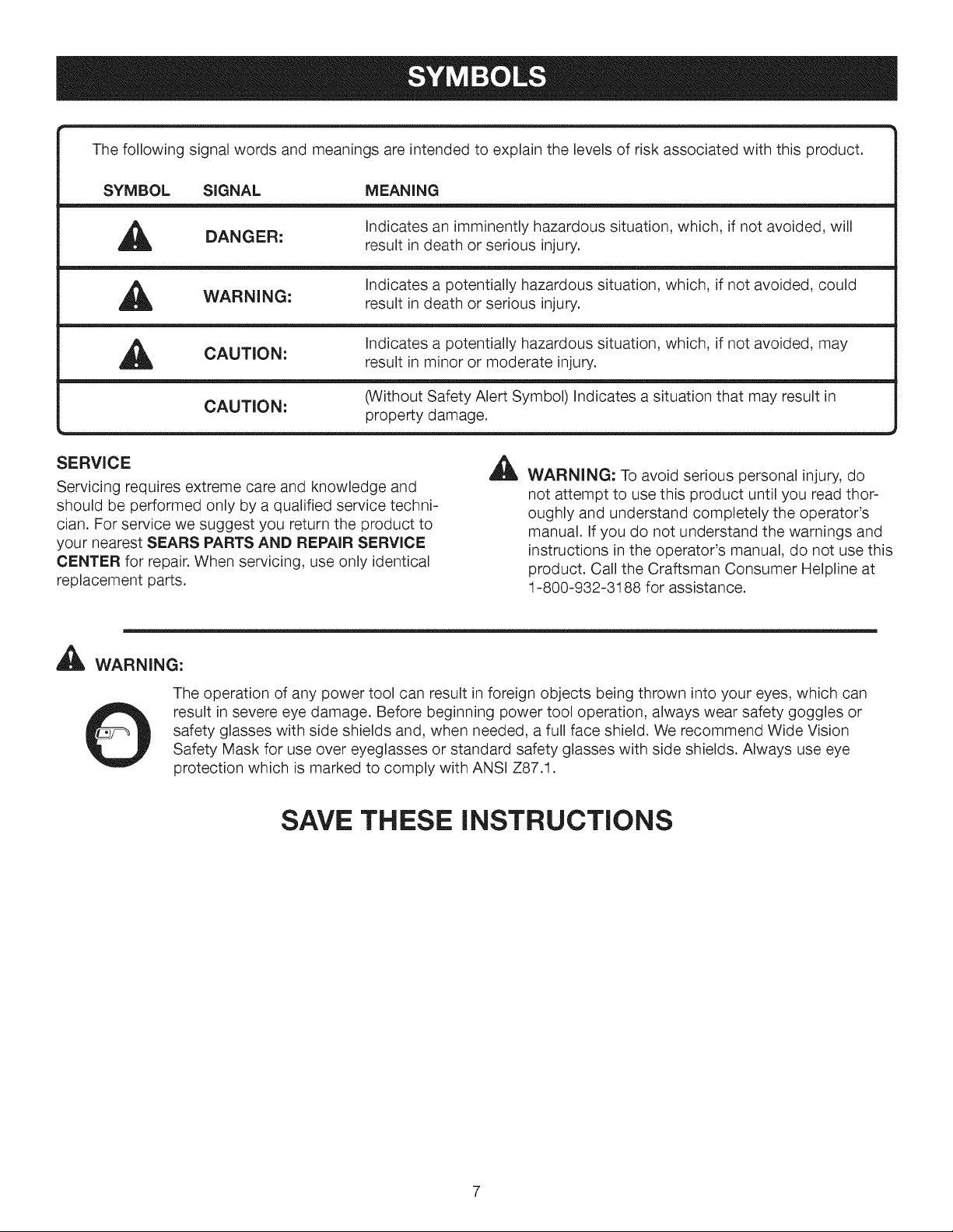
Thefollowingsignalwordsandmeaningsareintendedtoexplainthelevelsofriskassociatedwiththisproduct.
SYMBOL SIGNAL MEANING
DANGER:
WARNING:
,_ CAUTION:
CAUTION: (Without Safety Alert Symbol) Indicates a situation that may result in
SERVICE
Servicing requires extreme care and knowledge and
should be performed only by a qualified service techni-
cian. For service we suggest you return the product to
your nearest SEARS PARTS AND REPAIR SERVICE
CENTER for repair. When servicing, use only identical
replacement parts.
411_ILWARNING:
Indicates an imminently hazardous situation, which, if not avoided, will
result in death or serious injury.
Indicates a potentially hazardous situation, which, if not avoided, could
result in death or serious injury.
Indicates a potentially hazardous situation, which, if not avoided, may
result in minor or moderate injury.
property damage.
_ WARNING: To avoid serious personal injury, do
not attempt to use this product until you read thor-
oughly and understand completely the operator's
manual. If you do not understand the warnings and
instructions in the operator's manual, do not use this
product. Call the Craftsman Consumer Helpline at
1-800-932-3188 for assistance.
The operation of any power tool can result in foreign objects being thrown into your eyes, which can
result in severe eye damage. Before beginning power tool operation, always wear safety goggles or
safety glasses with side shields and, when needed, a full face shield. We recommend Wide Vision
Safety Mask for use over eyeglasses or standard safety glasses with side shields. Always use eye
protection which is marked to comply with ANSI Z87.1.
SAVE THESE INSTRUCTIONS
DOUBLE INSULATION
Double insulation is a concept in safety in electric power
tools, which eliminates the need for the usual three-wire
grounded power cord. All exposed metal parts are
isolated from the internal metal motor components with
protecting insulation. Double insulated tools do not need
to be grounded.
A
WARNING: The double insulated system is
intended to protect the user from shock resulting
from a break in the tool's internal insulation. Observe
all normal safety precautions to avoid electrical
shock.
NOTE: Servicing of a product with double insulation
requires extreme care and knowledge of the system and
should be performed only by a qualified service techni-
cian. For service, we suggest you return the product to
your nearest Sears or other qualified service center for
repair. Always use original factory replacement parts when
servicing.
ELECTRICAL CONNECTION
This product has a precision-built electric motor. It should
be connected to a power supply that is 120 volts, 60 Hz,
AC only (normal household current). Do not operate this
product on direct current (DC). A substantial voltage drop
will cause a loss of power and the motor will overheat. If
the product does not operate when plugged into an outlet,
double-check the power supply.
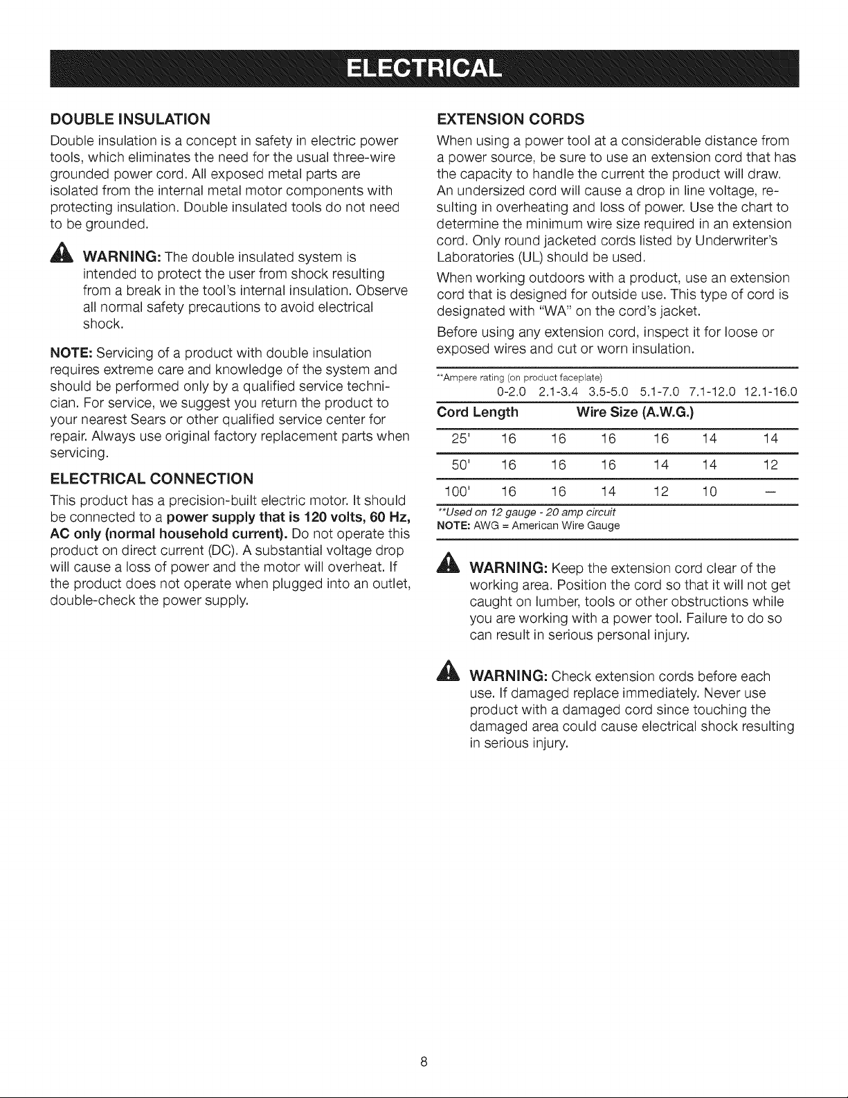
EXTENSION CORDS
When using a power tool at a considerable distance from
a power source, be sure to use an extension cord that has
the capacity to handle the current the product will draw.
An undersized cord will cause a drop in line voltage, re-
sulting in overheating and loss of power. Use the chart to
determine the minimum wire size required in an extension
cord. Only round jacketed cords listed by Underwriter's
Laboratories (UL) should be used.
When working outdoors with a product, use an extension
cord that is designed for outside use. This type of cord is
designated with "WA" on the cord's jacket.
Before using any extension cord, inspect it for loose or
exposed wires and cut or worn insulation.
**Ampere rating (on product faceplate)
Cord Length Wire Size (A.W.G.)
25' 16 16 16 16 14 14
50' 16 16 16 14 14 12
100' 16 16 14 12 10 --
**Used on 12 gauge - 20 amp circuit
NOTE: AWG = American Wire Gauge
A
0-2.0 2.1-3.4 3.5-5.0 5.1-7.0 7.1-12.0 12.1-16.0
WARNING: Keep the extension cord clear of the
working area. Position the cord so that it will not get
caught on lumber, tools or other obstructions while
you are working with a power tool. Failure to do so
can result in serious personal injury.
A
WARNING: Check extension cords before each
use. If damaged replace immediately. Never use
product with a damaged cord since touching the
damaged area could cause electrical shock resulting
in serious injury.

Anti-KickbackPawls (radial arm and table saws)
A device which, when properly installed and maintained,
is designed to stop the workpiece from being kicked back
toward the front of the saw during a ripping operation.
Arbor
The shaft on which a blade or cutting tool is mounted.
Bevel Cut
A cutting operation made with the blade at any angle
other than 90° to the table surface.
Chamfer
A cut removing a wedge from a block so the end (or part
of the end) is angled rather than at 90°.
Compound Cut
A cross cut made with both a miter and a bevel angle.
Cross Cut
A cutting or shaping operation made across the grain or
the width of the workpiece.
Cutter Head (planers and jointer planers)
A rotating cutterhead with adjustable blades or knives.
The blades or knives remove material from the workpiece.
Dado Cut
A non-through cut which produces a square-sided notch
or trough in the workpiece (requires a special blade).
Featherboard
A device used to help control the workpiece by guiding it
securely against the table or fence during any ripping
operation.
FPM or SPM
Feet per minute (or strokes per minute), used in reference
to blade movement.
Freehand
Performing a cut without the workpiece being guided by a
fence, miter gauge, or other aids.
Gum
A sticky, sap-based residue from wood products.
Heel
Alignment of the blade to the fence.
Kerr
The material removed by the blade in a through cut or the
slot produced by the blade in a non-through or partial cut.
Kickback
A hazard that can occur when the blade binds or stalls,
throwing the workpiece back toward operator.
Leading End
The end of the workpiece pushed into the tool first.
Miter Cut
A cutting operation made with the workpiece at any angle
to the blade other than 90 °.
Non-Through Cuts
Any cutting operation where the blade does not extend
completely through the thickness of the workpiece.
Push Blocks (for jointer planers)
Device used to feed the workpiece over the jointer planer
cutterhead during any operation. This aid helps keep the
operator's hands well away from the cutterhead.
Push Blocks and Push Sticks (for table saws)
Devices used to feed the workpiece through the saw
blade during cutting operations. A push stick (not a push
block) should be used for narrow ripping operations.
These aids help keep the operator's hands well away from
the blade.
Pilot Hole (drill presses)
A small hole drilled in a workpiece that serves as a guide
for drilling large holes accurately.
Resaw
A cutting operation to reduce the thickness of the
workpiece to make thinner pieces.
Resin
A sticky, sap-based substance that has hardened.
Revolutions Per Minute (RPM)
The number of turns completed by a spinning object in
one minute.
Ripping or Rip Cut
A cutting operation along the length of the workpiece.
Riving Knife/Spreader/Splitter (table saws)
A metal piece, slightly thinner than the blade, which helps
keep the kerf open and also helps to prevent kickback.
Saw Blade Path
The area over, under, behind, or in front of the blade. As
it applies to the workpiece, that area which will be or has
been cut by the blade.
Set
The distance that the tip of the saw blade tooth is bent (or
set) outward from the face of the blade.
Snipe (planers)
Depression made at either end of a workpiece by cutter
blades when the workpiece is not properly supported.
Through Sawing
Any cutting operation where the blade extends completely
through the thickness of the workpiece.
Throw-Back
The throwing back of a workpiece usually caused by the
workpiece being dropped into the blade or being 9laced
inadvertently in contact with the blade.
Workpiece or Material
The item on which the operation is being done.
Worktable
Surface where the workpiece rests while performing a
cutting, drilling, planing, or sanding operation.
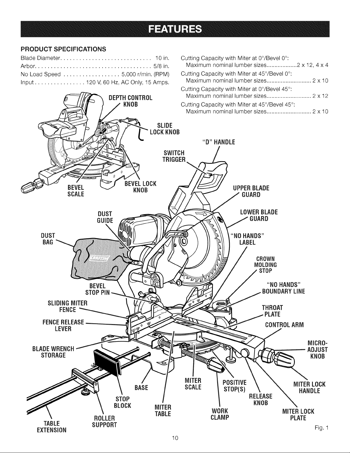
PRODUCT SPECiFICATiONS
Blade Diameter ............................. 10 in. Cutting Capacity with Miter at 0°/Bevel 0°:
Arbor ..................................... 5/8 in. Maximum nominal lumber sizes ................... 2 x 12, 4 x 4
No Load Speed .................. 5,000 r/rain. (RPM) Cutting Capacity with Miter at 45°/Bevel 0°:
Input ................ 120 V, 60 Hz, AC Only, 15 Amps. Maximum nominal lumber sizes ............................ 2 x 10
Cutting Capacity with Miter at 0°/Bevel 45°:
,- ,,,,L ,,_ DEPTHCONTROL Maximum nominal lumber sizeS.o............... '_........... 2 x 12
_/_ r-_ ) / KNOB Cutting Capacity with Miter at 45/Bevel 45 :
/f__ / / Maximum nominal lumber sizes ............................ 2 x 10
\ [
LOCKKNOB
SWITCH
SCALE GUARD
DUST LOWERBLADE
GUIDE GUARD
DUST "NO HANDS"
BAG LABEL
BEVEL "NO HANDS"
STOPPiN BOUNDARYLINE
SLIDINGMITER
FENCE
FENCERELEASE
LEVER
"D" HANDLE{
CROWN
MOLDING
STOP
THROAT
PLATE
CONTROLARM
MICRO-
BLADEWRENCH ADJUST
STORAGE KNOB
MITER POSITIVE MITERLOCK
BASE SCALE STOP(S) HANDLE
STOP RELEASE
BLOCK MITER KNOB
ROLLER CLAMP PLATE
TABLE SUPPORT
EXTENSION Fig. 1
TABLE WORK MITERLOCK
10
KNOWYOUR COMPOUND MITER SAW
See Figure 1.
The safe use of this product requires an understanding of
the information on the tool and in this operator's manual
as well as a knowledge of the project you are attempting.
Before use of this product, familiarize yourself with all
operating features and safety rules.
10 in. BLADE
A 10 in. blade is included with your compound miter saw.
It will cut materials up to11-1/2 in. wide, depending upon
the angle at which the cut is being made.
15 AMP MOTOR
Your saw has a powerful 15 amp belt-driven motor with
sufficient power to handle tough cutting jobs. It is made with
all ball bearings, and has externally accessible brushes for
ease of servicing.
BEVEL LOCK KNOB
The bevel lock knob securely locks your compound miter
saw at desired bevel angles. A positive stop adjustment
screw has been provided on each side of the saw arm.
These adjustment screws are for making fine adjustments
at 0° and 45°.
BEVEL STOP PIN
The bevel stop pin has several positions:
1. Override (pin pulled completely out)
2. The 0° - 48 ° position for crown molding (pin pushed in)
3. Stops at 33.9 ° and 45°
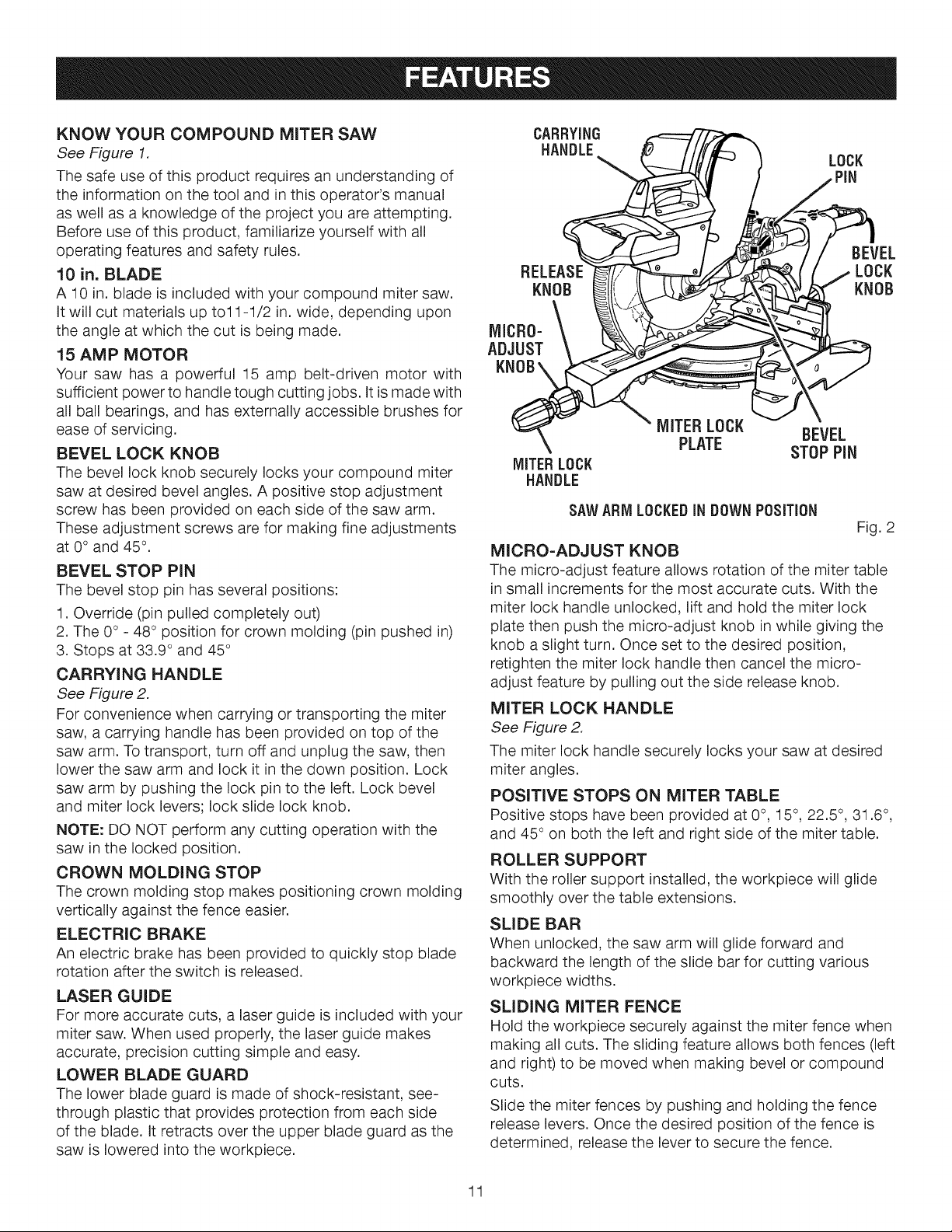
CARRYING HANDLE
See Figure 2.
For convenience when carrying or transporting the miter
saw, a carrying handle has been provided on top of the
saw arm. To transport, turn off and unplug the saw, then
lower the saw arm and lock it in the down position. Lock
saw arm by pushing the lock pin to the left. Lock bevel
and miter lock levers; lock slide lock knob.
NOTE: DO NOT perform any cutting operation with the
saw in the locked position.
CROWN MOLDING STOP
The crown molding stop makes positioning crown molding
vertically against the fence easier.
ELECTRIC BRAKE
An electric brake has been provided to quickly stop blade
rotation after the switch is released.
LASER GUIDE
For more accurate cuts, a laser guide is included with your
miter saw. When used properly, the laser guide makes
accurate, precision cutting simple and easy.
LOWER BLADE GUARD
The lower blade guard is made of shock-resistant, see-
through plastic that provides protection from each side
of the blade. It retracts over the upper blade guard as the
saw is lowered into the workpiece.
CARRYING
HANDLE_ LOCK
RELEASE_J_ _ ( / ., LOCK
Nj MICR0"\ °
MITERLOCK BEVEL
MITERLOCK
HANDLE
SAWARM LOCKEDIN DOWNPOSiTiON
MICRO-ADJUST KNOB
The micro-adjust feature allows rotation of the miter table
in small increments for the most accurate cuts. With the
miter lock handle unlocked, lift and hold the miter lock
plate then push the micro-adjust knob in while giving the
knob a slight turn. Once set to the desired position,
retighten the miter lock handle then cancel the micro-
adjust feature by pulling out the side release knob.
MITER LOCK HANDLE
See Figure 2.
The miter lock handle securely locks your saw at desired
miter angles.
POSITIVE STOPS ON MITER TABLE
Positive stops have been provided at 0°, 15°, 22.5°, 31.6 °,
and 45° on both the left and right side of the miter table.
ROLLER SUPPORT
With the roller support installed, the workpiece will glide
smoothly over the table extensions.
SLIDE BAR
When unlocked, the saw arm will glide forward and
backward the length of the slide bar for cutting various
workpiece widths.
SLIDING MITER FENCE
Hold the workpiece securely against the miter fence when
making all cuts. The sliding feature allows both fences (left
and right) to be moved when making bevel or compound
CutS.
Slide the miter fences by pushing and holding the fence
release levers. Once the desired position of the fence is
determined, release the lever to secure the fence.
PLATE STOPPiN
Fig. 2
11
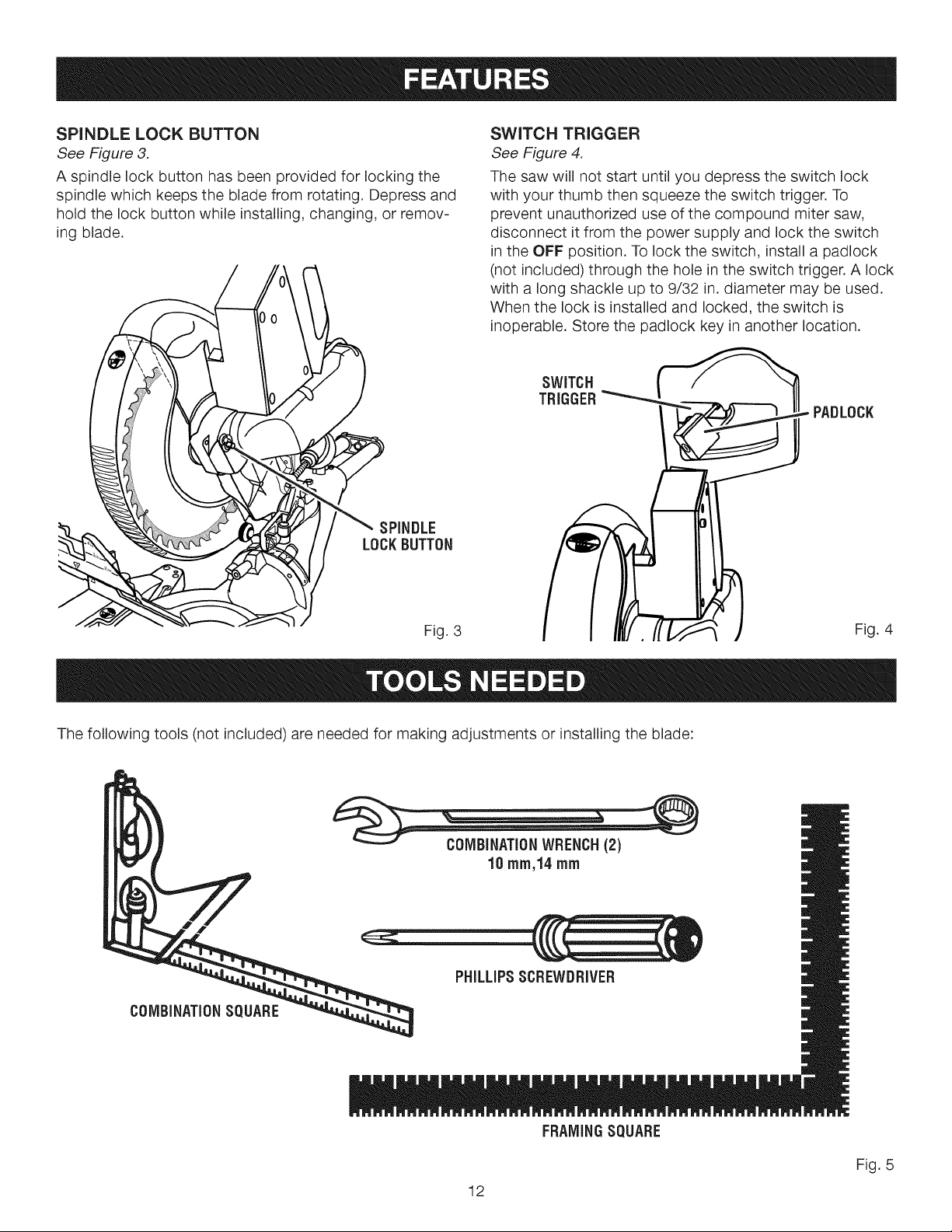
SPINDLELOCK BUTTON
See Figure 3.
A spindle lock button has been provided for locking the
spindle which keeps the blade from rotating. Depress and
hold the lock button while installing, changing, or remov-
ing blade.
SWITCH TRIGGER
See Figure 4.
The saw will not start until you depress the switch lock
with your thumb then squeeze the switch trigger. To
prevent unauthorized use of the compound miter saw,
disconnect it from the power supply and lock the switch
in the OFF position. To lock the switch, install a padlock
(not included) through the hole in the switch trigger. A lock
with a long shackle up to 9/32 in. diameter may be used.
When the lock is installed and locked, the switch is
inoperable. Store the padlock key in another location.
SWITCH
TRIGGER Itl
SPINDLE
LOCKBUTTON
Fig. 3
The following tools (not included) are needed for making adjustments or installing the blade:
PADLOCK
Fig. 4
PHiLLiPSSCREWDRIVER
FRAMINGSQUARE
12
Fig. 5
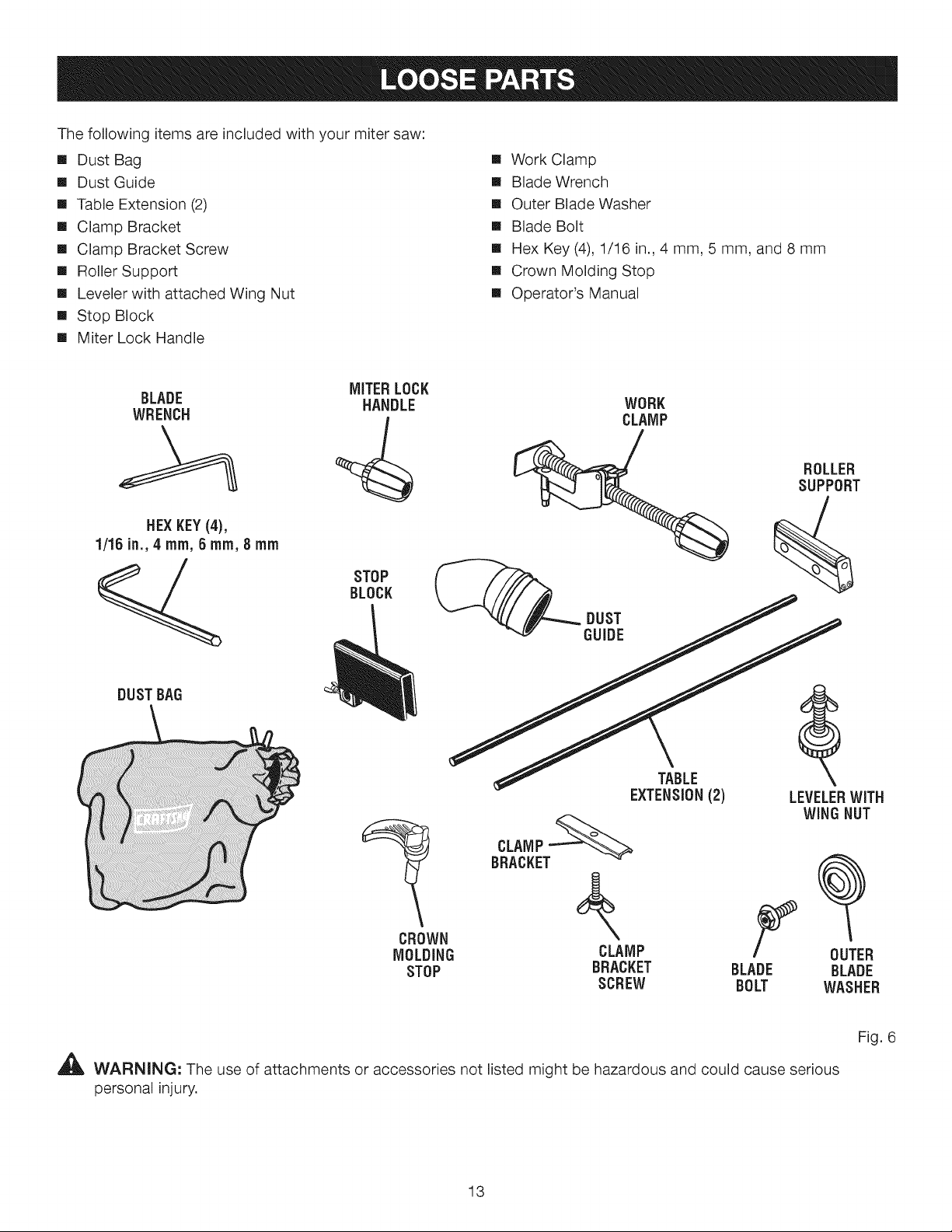
Thefollowingitemsareincludedwithyourmitersaw:
[] DustBag [] WorkClamp
[] DustGuide [] BladeWrench
[] TableExtension(2) [] OuterBladeWasher
[] ClampBracket [] BladeBolt
[] ClampBracketScrew [] HexKey(4),1/16in.,4 mm,5mm,and8mm
[] RollerSupport [] CrownMoldingStop
[] LevelerwithattachedWingNut [] Operator'sManual
[] StopBlock
[] MiterLockHandle
BLADE WORK
WRENCH CLAMP
HEXKEY(4),
1/16 in., 4 ram, 6 ram, 8 mm
DUSTBAG
MITERLOCK
HANDLE
STOP
BLOCK
TABLE
EXTENSION(2)
ROLLER
SUPPORT
LEVELERWiTH
WINGNUT
CROWN \
MOLDING CLAMP
STOP BRACKET
SCREW
,_ WARNING: The use of attachments or accessories not listed might be hazardous and could cause serious
personal injury.
13
F
BLADE
BOLT
OUTER
BLADE
WASHER
Fig. 6
UNPACKING
Thisproductrequiresassembly.
[] Carefullyliftsawfromthecartonbythecarryinghandle
andthesawbase,andplaceitonalevelworksurface.
NOTE:Thissawisheavy.Toavoidbackinjury,liftwith
yourlegs,notyourback,andgethelpwhenneeded.
[] Thissawhasbeenshippedwiththesawarmsecured
inthedownposition.Toreleasethesawarm,push
downonthetopofthesawarm,cutthetie-wrap,and
pulloutonthelockpin.
[] Liftthesawarmbythehandle.Handpressureshould
remainonthesawarmtopreventsuddenriseupon
releaseofthetiewrap.
[] Inspectthetoolcarefullyto makesurenobreakageor
damageoccurredduringshipping.
[] Donotdiscardthepackingmaterialuntilyouhave
carefullyinspectedandsatisfactorilyoperatedthetool.
[] Thesawisfactorysetforaccuratecutting.After
assemblingit,checkforaccuracy.Ifshippinghas
influencedthesettings,refertospecificprocedures
explainedinthismanual.
[]
Ifanypartsaredamagedormissing,pleasecall
1-800-932-3188forassistance.
WARNING: If any parts are damaged or missing
do not operate this tool until the parts are replaced.
Failure to heed this warning could result in serious
personal injury.
A
WARNING: Do not attempt to modify this tool
or create accessories not recommended for use
with this tool. Any such alteration or modification is
misuse and could result in a hazardous condition
leading to possible serious personal injury.
WARNING: Do not connect to power supply until
assembly is complete. Failure to comply could result
in accidental starting and possible serious personal
injury.
A
WARNING: Do not start the miter saw without
checking for interference between the saw blade and
the sliding miter fences. Damage could result to the
blade if it strikes the miter fence during operation of
the saw.
A
WARNING: Always make sure the compound miter
saw is securely mounted to a workbench. Failure
to heed this warning can result in serious personal
injury.
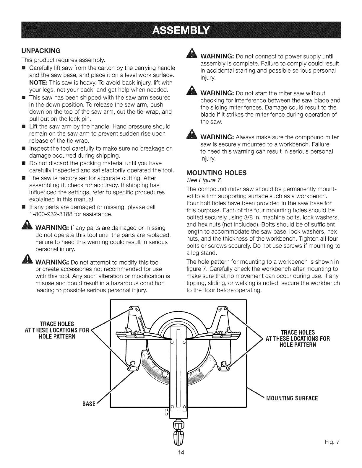
MOUNTING HOLES
See Figure 7.
The compound miter saw should be permanently mount-
ed to a firm supporting surface such as a workbench.
Four bolt holes have been provided in the saw base for
this purpose. Each of the four mounting holes should be
bolted securely using 3/8 in. machine bolts, lock washers,
and hex nuts (not included). Bolts should be of sufficient
length to accommodate the saw base, lock washers, hex
nuts, and the thickness of the workbench. Tighten all four
bolts or screws securely. Do not use screws if mounting to
a leg stand.
The hole pattern for mounting to a workbench is shown in
figure 7. Carefully check the workbench after mounting to
make sure that no movement can occur during use. If any
tipping, sliding, or walking is noted, secure the workbench
to the floor before operating.
TRACEHOLES
ATTHESELOCATIONSFOR
HOLEPATTERN
BASE
TRACEHOLES
ATTHESELOCATIONSFOR
HOLEPATTERN
MOUNTINGSURFACE
Fig. 7
14
NOTE:Manyoftheillustrationsinthismanualshowonly
portionsofthecompoundmitersaw.Thisisintentionalso
thatwecanclearlyshowpointsbeingmadeinthe
illustrations.Neveroperatethesawwithoutallguards
securelyin place and in good operating condition.
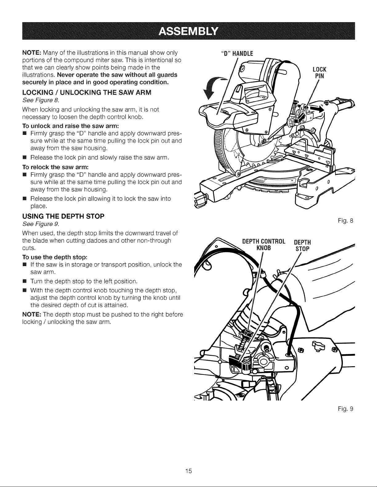
LOCKING / UNLOCKING THE SAW ARM
See Figure 8.
When locking and unlocking the saw arm, it is not
necessary to loosen the depth control knob.
To unlock and raise the saw arm:
[] Firmly grasp the "D" handle and apply downward pres-
sure while at the same time pulling the lock pin out and
away from the saw housing.
[] Release the lock pin and slowly raise the saw arm.
To relock the saw arm:
[] Firmly grasp the "D" handle and apply downward pres-
sure while at the same time pulling the lock pin out and
away from the saw housing.
[] Release the lock pin allowing it to lock the saw into
place.
USING THE DEPTH STOP
See Figure 9.
When used, the depth stop limits the downward travel of
the blade when cutting dadoes and other non-through
CutS.
To use the depth stop:
[] If the saw is in storage or transport position, unlock the
saw arm.
[] Turn the depth stop to the left position.
[] With the depth control knob touching the depth stop,
adjust the depth control knob by turning the knob until
the desired depth of cut is attained.
NOTE: The depth stop must be pushed to the right before
locking / unlocking the saw arm.
"D" HANDLE
LOCK
PiN
Fig. 8
DEPTHCONTROL DEPTH
KNOB STOP
15
Fig. 9
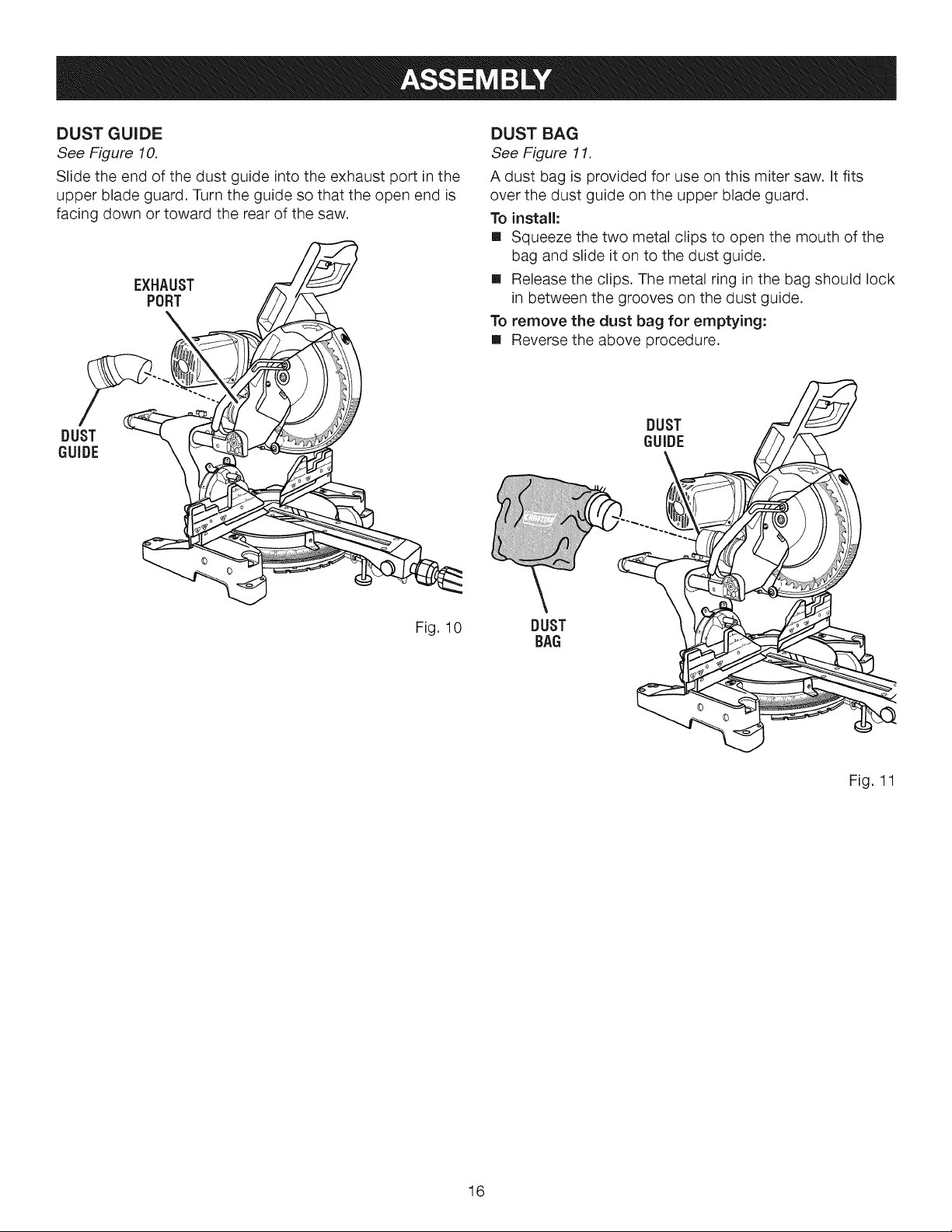
DUST GUIDE
See Figure 10.
Slide the end of the dust guide into the exhaust port in the
upper blade guard. Turn the guide so that the open end is
facing down or toward the rear of the saw.
EXHAUST
PORT
DUST BAG
See Figure 11.
A dust bag is provided for use on this miter saw. It fits
over the dust guide on the upper blade guard.
To install:
[] Squeeze the two metal clips to open the mouth of the
bag and slide it on to the dust guide.
[] Release the clips. The metal ring in the bag should lock
in between the grooves on the dust guide.
To remove the dust bag for emptying:
[] Reverse the above procedure.
DUST
GUIDE
DUST
GUIDE
©
Fig. 10
DUST
BAG
Fig. 11
16
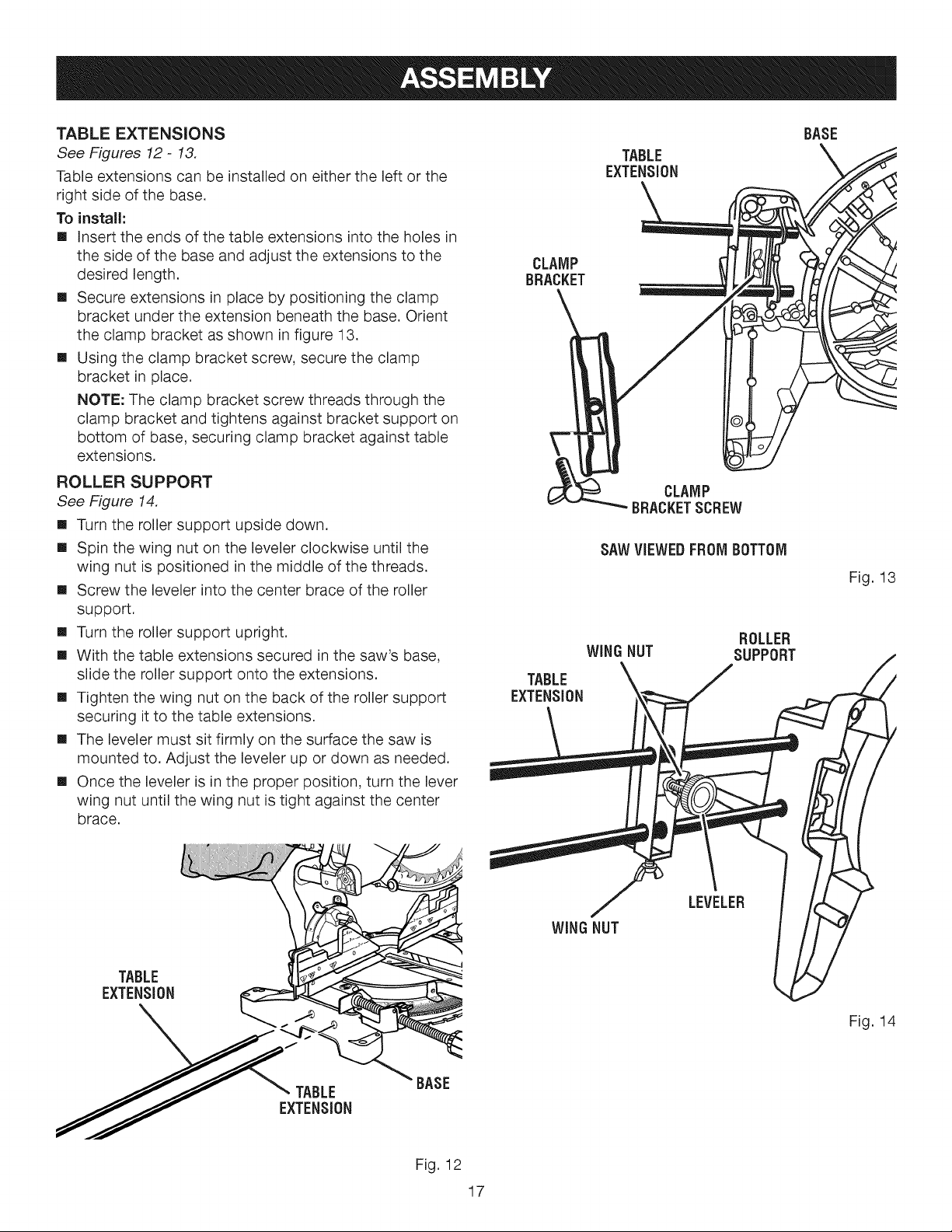
TABLEEXTENS(ONS
See Figures 12- 13.
Table extensions can be installed on either the left or the
right side of the base.
To instal(:
[] Insert the ends of the table extensions into the holes in
the side of the base and adjust the extensions to the
desired length.
[] Secure extensions in place by positioning the clamp
bracket under the extension beneath the base. Orient
the clamp bracket as shown in figure 13.
[] Using the clamp bracket screw, secure the clamp
bracket in place.
NOTE: The clamp bracket screw threads through the
clamp bracket and tightens against bracket support on
bottom of base, securing clamp bracket against table
extensions.
ROLLER SUPPORT
See Figure 14,
[] Turn the roller support upside down.
[] Spin the wing nut on the leveler clockwise until the
wing nut is positioned in the middle of the threads.
[] Screw the leveler into the center brace of the roller
support.
[] Turn the roller support upright.
[] With the table extensions secured in the saw's base,
slide the roller support onto the extensions.
[] Tighten the wing nut on the back of the roller support
securing it to the table extensions.
[] The leveler must sit firmly on the surface the saw is
mounted to. Adjust the leveler up or down as needed.
[] Once the leveler is in the proper position, turn the lever
wing nut until the wing nut is tight against the center
brace.
CLAMP
BRACKET
TABLE
EXTENSION
TABLE
EXTENSION
CLAMP
BRACKETSCREW
SAWVIEWEDFROMBOTTOM
WINGNUT
ROLLER
SUPPORT
BASE
Fig. 13
TABLE
EXTENSION
LEVELER
WING NUT
Fig. 14
BASE
Fig. 12
17
 Loading...