

Craftsman 315175010 Owner’s Manual

OWNER'S
MANUAL
MODEL NO.
315.175010
CAUTION:
Read Rules for
Safe Operation
and All Instruc-
tions Carefully
Thank You for Buying
Craftsman Tools
972000-339
CRRFTgMRN +
DUSTLESS
PLATE JOINER
DOUBLE INSULATED
®
Designed exclusivelyfor and sold only by
SEARS, ROEBUCK AND CO., Hoffman Estates, IL 60179
Printed in U.S.A.
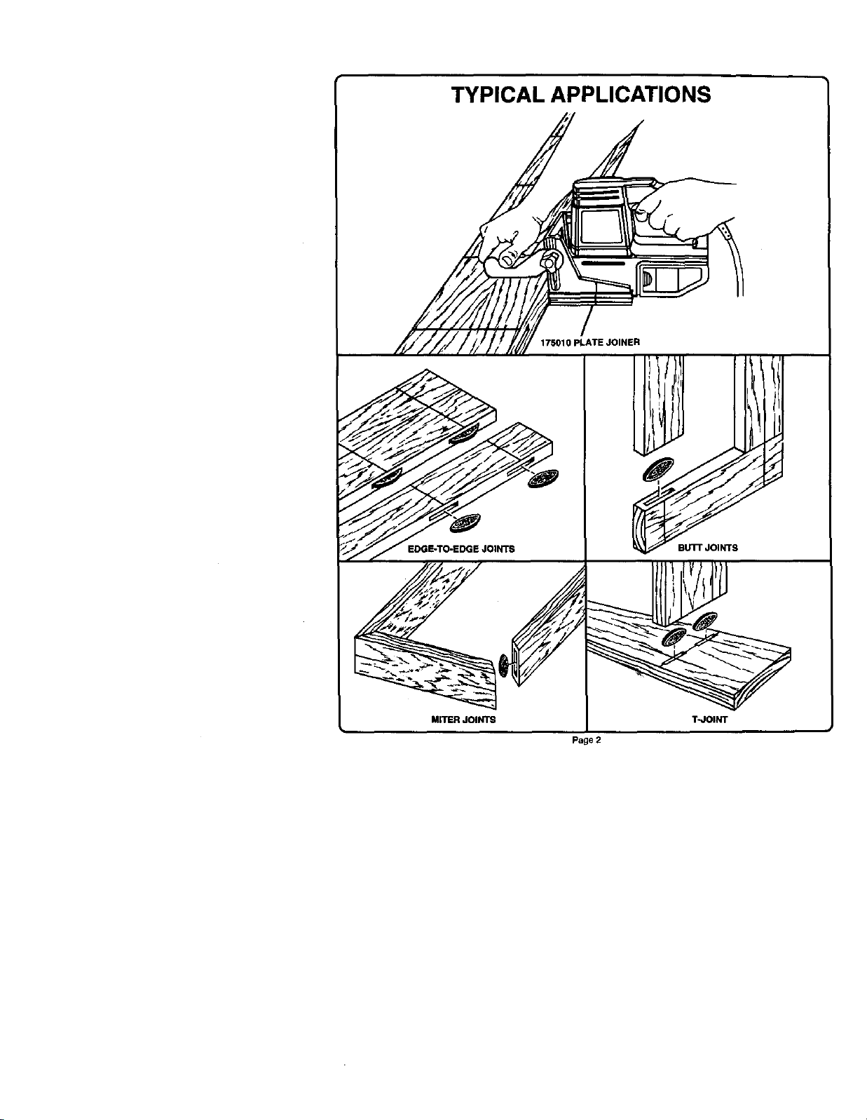
TYPICAL APPLICATIONS
175010 PLATE JOINER
Page 2

Table of Contents
I. Warranty and Introduction ....................................................................... 3
2. Rules For Safe Operation ..................................................................... 4-5
3. Features ................................................................................................ 6-7
4. Adjustments .......................................................................................... 8-9
5. Operation .......................................................................................... 10-16
6. Maintenance ..................................................................................... 17-19
7. Accessories ............................................................................................. 19
8. Troubleshooting ..................................................................................... 20
9, Exploded View and Parts List .......................................................... 22-23
FULL ONE YEAR WARRANTY ON CRAFTSMAN PLATE JOINER
Ifthis CraftsmanPlate Joinerfailstoperform propedydueto a defect inmate dal or workmanship withinoneyear from
the date of purchaseRETURN IT TO (OR CONTACT) THE NEAREST SEARS SERVICE CENTER I DEPARTMENT
IN THE UNITED STATES and Sears willrepair it,free ofcharge.
It this plate joiner is used for commercial or rental purpueasthiswarranty applies for only 90 days from the date of
purchase.
This warranty gives you specific legal dghts, and you may also have other dghts which vary from state to state.
SEARS, ROEBUCK AND CO.
DEPT. 817 WA
HOFFMAN ESTATES, IL 60179
INTRODUCTION
Spitne Joiner'/iso_e of the strongest methods of joinery usedinwoodworking, When glue is properly applied to a spline and
to the jointarea of the woodpieces being connected, a large surface area receives the adhesion propertiesoftheglue. This
forms a very strong joint.
Traditional spline Joiner'/requires cutting slots with a muter or table saw. Smafl, thin strips of wood must then he cut to fit
insidethe slots and act as splines.
Newer methods of spitne jokiery use a plate or biscuit joiner to cut precise mating oval slots in adjoining beards. Your new
platejoiner isa fast, simple, and accurate plunge cuttingtool that can be used for this purpose. If can be used to cutslotsin
hardwood, soft wood, plywood, particia board, and otherpressed woods.
Football shap4_lwafers, called biscuits, are then placed Inside the slots with"glue and used to help line up adjoining
surtames.When a water based glue is used, the biscuitsswell in the joint makingan extrem*dystrong and firm bond, White
glue,yellow glue. carpenters glue, hide glue, and kiiphatic resin glue are examples ofwater based glues.
This bondingtechnique has trediflo_tallybeen limitedto makingedge-to-edge joints, However, withthe use of your new
platejoiner, biscuitscan now be easily usedto connect butt, miter,and T-joints. Biscuitjoining can be as stronglu_mortise
and tenon, tongueand groova, standard8pllne, anddoweled joints. In mostcases the material around the biacuit will break
before the biscuitItaeit will break. A greater Igrtge area Ill8xpoI4rdto glue ina bl_uit joint, rnaidng the seams stronger.
Page 3

RULES FOR SAFE OPERATION
READ ALL INSTRUCTIONS
1, KNOW YOUR POWER TOOL - Read owner's
manualcarefully,Learnitsapplications and limi-
tationsas wellas the specificpotentialhazards
relatedto thistool.
2. GUARD AGAINST ELECTRICAL SHOCK BY
PREVENTING BODY CONTACT WITH
GROUNDED SURFACES. For example: Pipes,
radiators,ranges,refrigerator enclosures.
3. KEEP WORK AREA CLEAN. Cluttered areas
and benchesinviteaccidents.
4. AVOID DANGEROUS ENVIRONMENT. Don't
use power tools in damp or wet locations or
expose torain. Keep workarea well lit
5. KEEP CHILDREN AND VISITORS AWAY. A{I
visitorsshouldwear safetyglassesand bekepta
safe distancefrom workarea. Do not letvisitors
contacttoolorextensioncord.
6. STORE IDLE TOOLS. When not in use tools
shouldbe storedina dry, highorlocked-upplace
- outof the reach ofchildren.
7. DON'TFORCE TOOL Itwiltdothejobbetterand
saferat the ratefor whichitwasdesigned.
8. USE RIGHT TOOL. Don't force small tool or
attachment to do the job of a heavy duty tool.
Don't use tool for purpose not intended - for
example- Don'tuseacircularsawforcuttingtree
limbsor logs.
9. DRESS PROPERLY. Do notwear looseclothing
orjewelry. They can be caughtin movingparts.
Rubberglovesandnon-skidfootweararerecom-
mendedwhenworkingoutdoors.Also,wearpro-
tactive haircoveringtocontainlonghairandkeep
itfrom beingdrawnintoair vents.
10. ALWAYS WEAR SAFETY GLASSES WITH
SIDE SHIELDS. Everydayeyeglasseshaveonly
impact resJstsntlenses; they are NOT safety
glasses.
11. PROTECT YOUR LUNGS. Wear a face or dust
mask ifoperationis dusty.
12. PROTECT YOUR HEARING. Wear hearingpro-
taction during extendedpedodsof operation.
13. DON'T ABUSE CORD. Never carry tool by cord
or yank it to disconnect from receptacle. Keep
cord from heat, oil, and sharp edges.
14. SECURE WORK. Use clamps or a vise to hold
work. It's safer than using your hand and it frees
both hands to operate tool.
15, DON'T OVERREACH. Keep proper footing and
balance at all times. Do not use on a ladder or
unstable support
16. MAINTAIN TOOLS WITH CARE. Keep tools
sharp at all times, and clean for best and safest
performance. Follow instructions for lubricating
and changing accessories.
17. DISCONNECTTOOLS. When not in use, before
servicing, orwhen changing attachments, blades,
bits, cutters, etc., all tools should be discon-
nected.
18, REMOVE ADJUSTING KEYS AND
WRENCHES. Form habit of checking to see that
keys and adjusting wrenches are removed from
tool before turning it on.
19. AVOID ACCIDENTAL STARTING. Don't carry
plugged-in tool with finger on switch. Be sure
switch is off when plugging in.
20. MAKE SURE YOUR EXTENSION CORD IS IN
GOOD CONDITION. When using an extension
cord, be su re touse one heavy enough tocarry the
currentyour product willdraw. An undersized cord
will cause a drop in line voltage resulting in loss of
power and overheating. A wire gage size (A.W.G.)
of at least 16 is recommended for an extension
cord 100 feet or less in length. A cord exceeding
1GOfeet is not recommended. If in doubt, use the
next heavier gage. The smaller the gage number,
the heavier the cord.
21. OUTDOOR USE EXTENSION CORDS. When
tool is used outdoors, use only extension cords
intended for use outdoors. Outdoor approved
cords are marked with the suffix W-A, for example
- SJTW-A or SJOW-A.
22. KEEP BLADES CLEAN AND SHARP. Sharp
blades minimize stalling and kickback.
Page 4

RULES FOR SAFE OPERATION (Continued)
23 KEEP HANDS AWAY FROM CUTTING AREA.
Keep hands away from blades. Do not reach
underneath work while blade is rotating, WARN-
ING: BLADES COAST AFTER TURN OFF.
24, NEVER USE IN AN EXPLOSIVE ATMOSPHERE.
Normal sparking of the motor couid ignite flam-
mable liquids, gases, or fumes.
25. INSPECT TOOL CORDS PERIODICALLY and if
damaged, have repaired byan authodzed service
facility. Stay constantly aware of cord location
and keep it well away from the rotating blade.
26, INSPECT EXTENSION CORDS PERIODICALLY
and replace ifdamaged.
27. KEEP HANDLES DRY, CLEAN, AND FREE
FROM OIL AND GREASE. Always use a clean
cloth when cleaning. Never use brake fluids,
gasoline, petroleum-based products, or any strong
solvents to clean your tool.
28 STAY ALERT AND EXERCISE CONTROL.
Watch what you are doing and use common
sense. Do not operate tool when you are tired, Do
not rush,
29. CHECK DAMAGED PARTS. Before further use
of the tool, a guard or other part that is damaged
should be carefully checked to determine that it
will operate propedy and perform its intended
function. Check for alignment of moving parts,
binding of moving parts, breakage of parts, mount-
ing, and any other conditions that may affect its
operation. A guard or other part that is damaged
should be propady repaired or replaced by an
authorized service center.
30. DO NOT USE TOOL IF SWITCH DOES NOT
TURN IT ON AND OFF. Have defective switches
replaced by an authorized service center.
31, DO NOT OPERATE THIS TOOL WHILE UNDER
THE INFLUENCE OF DRUGS, ALCOHOL, OR
ANY MEDICATION.
32. GUARD AGAINST KICKBACK. Kickback oc-
curs when the blade stalls rapidly and the plate
joiner is ddven in the direction opposite blade
rotation. Release switch immediately ifblade binds
orjoiner stalls.
33. USE ONLY 4 INCH DIAMETER SPECIRED
BLADES. Do not use blades with incorrect size
holes. Never use b;ade washers or bolts that are
defective, incorrect, or not specified.
34. AVOID cUTnNG NAILS. Inspect forand remove
all nails from lumber before cutting,
35. NEVER touch the blade or other moving parts
dudng use,
36. NEVER start a tool when the blade is in contact
with the workpiece,
37, NEVER lay a tool down before the blade has
come to a compiota stop.
38. POLARIZED PLUGS. To reduce the dsk of elec-
tric shock, this equipment has a polarized plug
(one blade is wider than the other). This plug will
fit in a polarized outlet only one way. If the plug
does not fit fully in the outlet, reverse the plug. If
it stilldoes not fit, contact aqualified eioctdcian to
install the proper outlet. Do not change the plugin
any way.
39. When servicing use only Identlcst Craftsman
replacement parts.
40. SAVE THESE INSTRUCTIONS. Refer to them
freqLlently and use them to instruct others who
may use this tool. If you loan someone this tool,
loan them these instructions also.
m
which can resultIn imvere eye damage. Before beginning power fool opefat tan, stways wear |
safety goggles of msfotygllmsee with side shields and a full face shield when needed. We |
[_ The operation of any power tool can result in-foreign objects bstng thrOWn Into your eyes,
roeommend Wide Vision Safety MaSk for use over eyeglasses or standard safety glm I
with elde shields, avelloble at Sears Retell Stores.
Page 5
)
FEATURES
Your Plata Joiner has been designed for making fast, accurate, and simple plunge cutsin wood, etc. so that biscuitscan be
used to join twoor more boards together. When usedpmpedy and only for whet it isintended, thisversatgetoolwill give you
yearnof troubta-tree berforrnance, it isprofesslenally engleeered, but its ease of operaiton allewsthe amateur ta preducework
that is beautiful and precise.
DOUBLE INSULATED
This toot is double insulated. Double Insulationisa concept
insafely, inelectric powertools,whichelhelnatastheneedfor
the usual three wire grounded power cord end grounded
supply system. Wherever there is electric cutTentinthetool
there are twocomplete setsof insulationto protectthe user.
All exposed metal partsare isolatedfrominternalmetalmotor
components with protecting insulation.
IMPORTANT - Servicing of a tool with double insulation
requires extreme care and knowledge of the system and
should be performed only by a quaJifiedsePAceteChniCian.
For service we suggest you return the tool to your nearest
Searsstoreforrepair. Alwaysuseodgtsalfactoryredlacement
parts when servicing,
SWITCH
TO turn your plate joiner "ON", depress the switchtrigger,
Release switch trigger to turnyour plate joiner "OFF=,
5/8 HORSEPOWER MOTOR
Your plate joiner has a powerful 5/8horsepower motorwith
sutticientpowertohandle toughcuttingjobe. Itdevelops a no
load speed of 10,000 RPM,
CARBIDE TIPPED BLADE
Your plate joiner has an 8 tooth carbide tipped blade for
cuttingbiscuitstets,
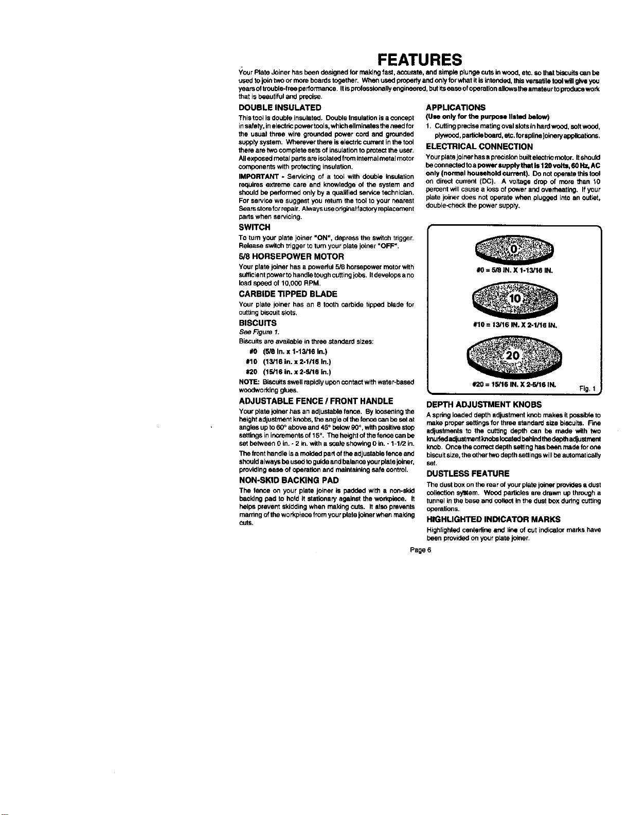
BISCUITS
S_ Figure 1.
Biscuitsare available in three standard sizes:
#O (5/8 In. x 1-13/16 th.)
#10 (13/16 In. x 2-1116 In.)
#20 (15/16 In. x 2-S/16 in.)
NOTE: Biscuitsswell rapidly uponcontact withwatar-based
woodworking glues•
ADJUSTABLEFENCE / FRONTHANDLE
Your plate joiner has an adjustable fence. By looseningthe
height adjustment knobs, the angle ofthe fence can be set at
angles upto 60_ above and45° belew90°, with positivestab
settingsin incrementsof15°. The height of the fence can be
set between 0 in. - 2 in.with a scale showing 0 in, - 1-1/2 in.
The front handle is a rnokled part of the adjustable fenceand
shouldalways be usedto guide and balanceyour plate joiner,
provlding ease of operation and maintaining safe control.
NON-SKID BACKING PAD
The fence on your plate joiner is padded with a non-skid
backing pad to hold it stationa_ against the workpisce. It
he_ps prever_ skidding when makingcuts. italso prevents
marring ofthe workplece fromyour plate joiner whenmaking
CutS.
APPLICATIONS
(Use only for the purpose listed below)
1. Cuttingprecisematleg oval slots in hard wood,softwood,
plywood,pattislaboard, ets.for spllee Jok_eP/edplisatlens.
ELECTRICAL CONNECTION
Yourplate joiner hasa precisionbuilhelactdcmotan Itshould
beconneuted to a p<>wersupply that ts 120 vofts, tt0Hz, AC
only {normal household current). Donut operate this taol
on directcurrent (DC). A voltage drop of more than 10
percent willcause a less ofpower and overheating. If your
plate joiner does notoperate when plugged into an outlet,
double-check the power supply.
#O: 5/8 tN. X 1-13/16 IN.
#10 = 13/16 IN. X 2-1116 IN,
#20 : 15/16 IN. X 2-rd16 IN.
DEPTH ADJUSTMENT KNOBS
A springloaded depth adjustment knob makes iteds_ble to
make proper settit;gs for three standard size biscuits. Fine
adjustments to the cutting depth can be made with two
knuhededjust mentknobskicated behindthedepthacrlustment
knob, Oncethe correct depthsetting has been made for one
biscuitsize, the othertwo depth settingswill be automatically
set.
DUSTLESS FEATURE
The dust boxon the rear of yourplate joiner provides a dust
collection sylttem. Wood particles are drawn up through a
tunnel in the base and collect inthe dust box duitng cutting
operations.
HIQHLIGHTED INDICATOR MARKS
Highlightedcentadine and line of cut indicatormarks have
been providedon your plate joiner.
Page 6
Fig. I

FEATURES
KNOW YOUR PLATE JOINER
,_e Fibre 2.
Your plate Joinerhas been shipped €ompletely as_mbled end ready for use. Inspect it carefullyto make sure no breakage
or damage has occurred dudng shipping, ff any parts are damsged or missing, contact your local Seam store or Sears
authorized service center to ob(aln replacement parts before attempting tooperate your plate J_r_n
ThedU6tboxisalsolnstall6dontherearoftooL Its usewillhelpkeeptheworkareaclean. For mostefficient pick.upof wood
particles, emptydust box often.
8efo_m8ttempt_g to use eny toolfamiliarize yourself withall operating features andsafety requirements.
_r_l_ CENTERUNE I UNE SWITCH TRIGGER REAR HANDLE
Page 7

ADJUSTMENTS
DEPTH OF CUT ADJUSTMENTS
Your plate joiner can be adjusted to three standard cutting
depths to accommodate three standard size biscuits-- #0,
#10, and #20. Adjustments are made by engaging slots o_
depth adjustmentknobwith tabs onrear base assembly. For
exsmpta, when using a #0 size biscuit, rotate the depth
adjustment knobto the slot marked 0. When usinga #10 size
biscuit,rotate the depth adjustment knobto the slotmarked
10, and when using a #20 size biSCUitrotate the depth
adjustment knob tothe slot marked 20,
TO SET DEPTH ADJUSTMENT KNOB
1. Unplug your plata joiner.
_,_ ADJUSTMENT
DEPTH
KNOB
TABS
2. Pull knuhad adjustment knobs in the direction of the
arrow shown in figure 3. NOTE: Knobs are spdng
loaded, therfore puIllogthem in thedirectionofthearrow
shown putspressure onthe spring and reloases pres-
sure from thedepth adjustment knob.
3. Rotate depth adjustment knob until desired slotsetting
aligns with tabs on rear base assembly-- 0, 10, or 20.
4. Next release knurled adjustment knob_ applying pres-
sure from the sprthg on depth adjustment knob.
Make a testcut ina scrap piece of wo_d. Fit thecorrect size
biscuitloto biscuitslot. Ifbiscuitslnt istoodeep ortooshallow,
fine adjustmentsto the depth setting can bemade by loosen-
ing rear adjustment knob and making fine adjustments with
thefrontadjustment knob, Turningtrent knobforwardwiltcut
shallow biscuitslots, Turning front knob backwards will cut
deeper biscuitslots. The biscuitslot should bedeep enough
to allow slightly morethan one-half ofthe biscuitintotheslot.
This extraroom allowsforproperalignmentofthe woodbslng
joined.
TO MAKE FINE ADJUSTMENTS
See Figure 4.
1. Unplug your plate Joiner.
2. Loosenrear knuded adjustmentknob. This knob isused
as alocknutorjam nut only, Loosenby twistingit Inthe
opposite directionaway from frontknob.
3. Turn front knurled adjustment knob forward for a more
shallowcot, or backwards fora deeper cut.
4. Once desired depth ofcut is reached, held frontknobso
thatitwill not move out of adjustment, Next,tightenrear
knobagainst front knob,
5. Re_heck depth setting by making a test cut in a scrap
piece ofwood. Also periodicallycheck depth settingfor
acouracy,
PULL AND HOLD TO
ROTATE OEPTH
ADJUSTMENT KNOB
Page 8
KNOBS
ROTATETO
DESIRED sE'nlNG
IO, OR 20
TURN FORWARD
FOR SHALLOW
BISCUIT SLOTS
REAR BASE
ASSEMBLY
Fig. 3
Fig. 4
 Loading...