

Page 1
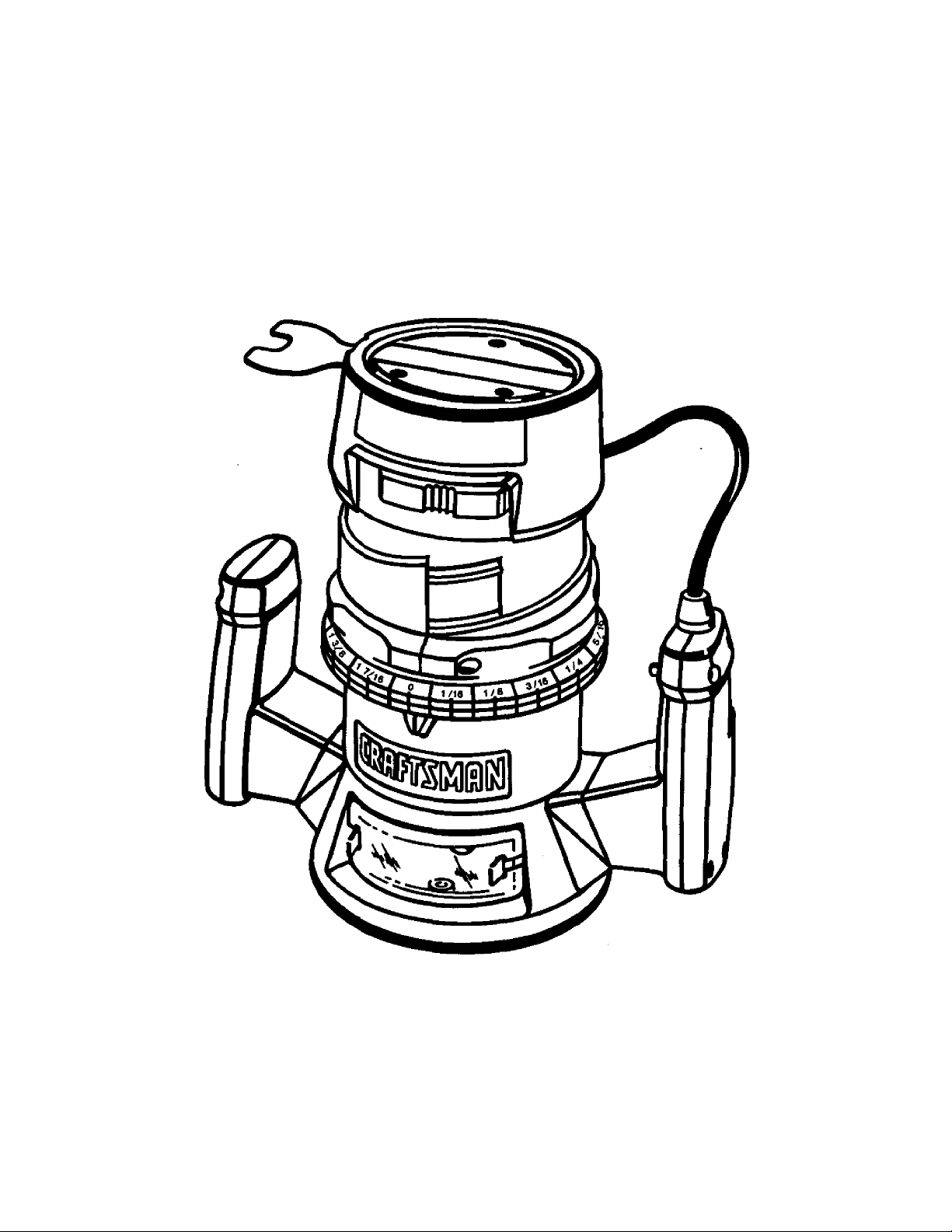
Owner's Manual
CRRFTSMRN
ROUTER
Double Insulated
Model No.
315.175000
Save this manual for
future reference
• Safety
A CAUTION: Read and
follow ail Safety Rules and
Operating Instructions before
first use of this product.
Sears, Roebuck and Co., Hoffman Estates, IL 60179 USA * P^rts List
Visit the Craftsman web page: www.sears.com/craftsman
972000-673
7-99
• Features
• Adjustments
• Operation
• Maintenance
Page 2

TABLE OF CONTENTS
Table Of Contents ....................................................................................................................................2
Warranty................................................................................................................................................. 2
Introduction...............................................................................................................................................2
Rules for Safe Operation......................................................................................................................... 3-4
Product Specifications................................................................................................................................5
Unpacking................................................................................................................................................ 5
Accessories............................................................................................................................................. 5
Features...................................................................................................................................................6
Adjustments...........................................................................................................................................7-9
Operation.............................................................................................................................................9-13
Maintenance...................................................................................................................................... 14-15
Exploded View and Repair Parts List.................................................................................................... 16-17
Parts Ordering / Service........................................................................................................................... 18
WARRANTY
FULL ONE YEAR WARRANTY ON CRAFTSMAN ROUTER
If this CRAFTSMAN Router fails to give complete satisfaction within one year from the date of purchase,
RETURN IT TO THE NEAREST SEARS STORE IN THE UNITED STATES, and Sears will repair it, free of
charge.
If this CRAFTSMAN Router is used for commercial or rental purposes, this warranty applies for only 90 days
from the date of purchase.
This warranty gives you specific legal rights, and you may also have other rights which vary from state to state.
Sears, Roebuck and Co., Dept. 817 WA, Hoffman Estates, IL 60179
INTRODUCTION
Your router has many features for making routing
operations more pleasant and enjoyable. Safety,
performance and dependability have been given top
priority in the design of this router making it easy to
maintain and operate.
A Look for this symbol to point out important safety precautions. It means attention!!! Your
safety is invoived.
CAUTION: Carefully read through this entire
owner's manual before using your new router.
Pay close attention to the Rules for Safe
Operation, Warnings and Cautions. If you use
your router properly and only for what it is
intended, you will enjoy years of safe, reliable
service.
^ WARNING:
The operation of any router can result in foreign objects being thrown into your eyes, which
can result in severe eye damage. Before beginning power tool operation, always wear safety
goggles or safety glasses with side shields and a full face shield when needed. We
recommend Wide Vision Safety Mask for use over eyeglasses or standard safety glasses
with side shields, available at Sears Retail Stores.
Page 3

RULES FOR SAFE OPERATION
The purpose of safety symbols Is to attract your attention to possible dangers. The safety symbols, and
the explanations with them, deserve your careful attention and understanding. The safety warnings do
not by themselves eliminate any danger. The instructions or warnings they give are not substitutes for
proper accident prevention measures.
SYMBOL MEANING
^ SAFETY ALERT SYMBOL:
Indicates danger, warning, or cairtion. May be used in conjunction with other symbols or pictographs.
DANGER: Failure to obey a safety warning will result in serious injury to yourself or to others.
Always follow the safety precautions to reduce the risk of fire, electric shock and personal injury.
A WARNING: Failure to obey a safety warning can result in serious injury to yourself or to others.
Always follow the safety precautions to reduce the risk of fire, electric shock and personal injury.
VL CAUTION: Failure to obey a safety warning may result in property damage or personal injury to
yourself or to others. Always follow the safety precautions to reduce the risk of fire, electric shock
and personal injury.
NOTE:
DOUBLE INSULATION
Double insulation is a concept in safety, in electric
power tools, which eliminates the need for the usual
three-wire grounded power cord. All exposed metal
parts are isolated from internal metal motor
components with protecting insulation. Double
insulated tools do not need to be grounded.
WARNING: Do not attempt to operate this tool
until you have read thoroughly and understand
completely all instructions, safety rules, etc.
contained in this manual. Failure to comply can
result in accidents involving fire, electric shock,
or serious personal injury. Save owner's manual
and review frequently for continuing safe
operation, and instructing others who may use
this tool.
READ ALL INSTRUCTIONS
■ KNOW YOUR POWER TOOL. Read owner's
manual carefully. Learn its appiications and
limitations as well as the specific potential hazards
related to this tool.
■ GUARD AGAINST ELECTRICAL SHOCK by
preventing body contact with grounded surfaces.
For example: pipes, radiators, ranges, refrigerator
enclosures.
■ KEEP GUARDS IN PLACE and in working order.
■ KEEP WORK AREA CLEAN. Cluttered areas and
benches invite accidents.
■ AVOID DANGEROUS ENVIRONMENT. Do
not use power tools in damp or wet locations or
expose to rain. Keep work area well lit.
Advises you of information or instructions vital to the operation or maintenance of the equipment.
IMPORTANT
Servicing of a tool with double insulation requires
extreme care and knowledge of the system and
should be performed only by a qualified service
technician. For service we suggest you return the tool
to your nearest Sears Store for repair. Always use
original factory replacement parts when servicing.
■ KEEP CHILDREN AND VISITORS AWAY. AH
visitors should wear safety glasses and be kept a
safe distance from work area. Do not let visitors
contact tool or extension cord.
■ STORE IDLE TOOLS. When not in use, tools
should be stored In a dry and high or locked-up
place - out of the reach of children.
■ DO NOT FORCE TOOL. It will do the job better
and safer at the rate for which it was designed.
■ USE RIGHT TOOL. Don't force small tool or
attachment to do the job of a heavy duty tool.
Don't use tool for purpose not intended — for
example — don't use a circular saw for cutting tree
limbs or logs.
■ WEAR PROPER APPAREL. Do not wear loose
clothing or jewelry that can get caught in tool's
moving parts and cause personal injury. Rubber
gloves and nonskid footwear are recommended
when working outdoors. Wear protective hair
covering to contain long hair and keep it from being
drawn into nearby air vents.
■ ALWAYS WEAR SAFETY GLASSES. Everyday
eyeglasses have only impact-resistant lenses; they
are not safety glasses.
■ PROTECT YOUR LUNGS. Wear a face or dust
mask if the operation is dusty.
Page 4

RULES FOR SAFE OPERATION (Continued)
PROTECT YOUR HEARING. Wear hearing
protection during extended periods of operation.
DO NOT ABUSE CORD. Never carry tooi by cord
or yank it to disconnect from receptacle. Keep cord
from heat, oil, and sharp edges.
SECURE WORK. Use clamps or a vise to hold
work. It is safer than using your hand and it frees
both hands to operate tool.
DO NOT OVERREACH. Keep proper footing and
balance at all times. Do not use on a ladder or
unstable support. Secure tools when working at
elevated positions.
MAINTAIN TOOLS WITH CARE. Keep tools sharp
and clean for best and safest performance. Follow
instructions for lubricating and changing accesso
ries.
DISCONNECT TOOLS. When not in use, before
servicing, or when changing attachments, tools
should be disconnected from power supply.
REMOVE ADJUSTING KEYS AND WRENCHES.
Form habit of checking to see that keys and
adjusting wrenches are removed from tool before
turning it on.
AVOID ACCIDENTAL STARTING. Do not carry
plugged-in tool with finger on switch. Be sure
switch is off when plugging in.
MAKE SURE YOUR EXTENSION CORD IS IN
GOOD CONDITION. When using an extension
cord, be sure to use one heavy enough to carry the
current your product will draw. An undersized cord
will cause a drop in line voltage resulting in loss of
power and overheating. A wire gage size (A.W.G.)
of at least 14 is recommended for an extension
cord 100 feet or less in length. A cord exceeding
100 feet is not recommended. If in doubt, use the
next heavier gage. The smaller the gage number,
the heavier the cord.
OUTDOOR USE EXTENSION CORDS. When tool
is used outdoors, use only extension cords suitable
for use outdoors. Outdoor approved cords are
marked with the suffix W-A, for example - SJTW-A
or SJOW-A.
I KEEP CUTTERS CLEAN AND SHARP. Sharp
cutters minimize stalling and kickback.
KEEP HANDS AWAY FROM ROUTING AREA.
Keep hands away from cutters. Do not reach under
neath work while cutter is rotating. Do not attempt to
remove material w^ile cutter is rotating.
1 NEVER USE IN AN EXPLOSIVE
ATMOSPHERE. Normal sparking of the motor
could ignite fumes.
I INSPECT TOOL CORDS PERIODICALLY and if
damaged, have repaired at your nearest Sears
Repair Center. Stay constantly aware of cord
location.
INSPECT EXTENSION CORDS
PERIODICALLY and replace if damaged.
KEEP HANDLES DRY, CLEAN, AND FREE
FROM OIL AND GREASE. Always use a clean
cloth when cleaning. Never use brake fluids,
gasoline, petroleum-based products, or any strong
solvents to clean your tool.
STAY ALERT AND EXERCISE CONTROL. Watch
what you are doing and use common sense. Do
not operate tool when you are tired. Do not rush.
CHECK DAMAGED PARTS. Before further use of
the tool, a guard or other part that is damaged
should be carefully checked to determine that it will
operate properly and perform its intended function.
Check for alignment of moving parts, binding of
moving parts, breakage of parts, mounting and any
other conditions that may affect its operation. A
guard or other part that is damaged should be
properly repaired or replaced by an authorized
service center.
DO NOT USE TOOL IF SWITCH DOES NOT
TURN IT ON AND OFF. Have defective switches
replaced by an authorized service center.
INSPECT FOR and remove all nails from lumber
before routing.
DO NOT operate this tool while under the influence
of drugs, alcohol, or any medication.
POLARIZED PLUGS. To reduce the risk of electric
shock, this tool has a polarized plug (one blade is
wider than the other). This plug will fit in a polar
ized outlet only one way. If the plug does not fit
fully in the outlet, reverse the plug. If it still does
not fit, contact a qualified electrician to install the
proper outlet. Do not change the plug in any way.
WHEN SERVICING USE ONLY IDENTICAL
CRAFTSMAN REPLACEMENT PARTS.
WHEN USING THIS ROUTER WITH A ROUTER
TABLE, HELP PREVENT POSSIBLE SERIOUS
INJURY BY KEEPING THE CUTTER GUARDED
AT ALL TIMES. Use only router tables, with
guards, that have been designed for use on routers
that are of this type, size, and weight.
DO NOT USE TOOL UNDER "BROWNOUT" OR
OTHER LOW VOLTAGE CONDITIONS. Also, do
not use with any device that could cause the power
supply voltage to change.
SAVE THESE INSTRUCTIONS. Refer to them
frequently and use them to instruct others who may
use this tool. If you loan someone this tool, loan
them these instructions also.
SAVE THESE INSTRUCTIONS
Page 5

PRODUCT SPECIFICATIONS
Depth of cut
Collet
0-1-1/2 in.
1/4 in.
Horsepower
Rating
120 volts, 60 Hz, AC only
Your router has been shipped completely assembled.
Inspect it carefully to make sure no breakage or
damage has occurred during shipping. If any parts are
damaged or missing, contact your nearest Sears
Retail Store to obtain replacement parts before
attempting to operate router. A wrench and this
Owner's Manual are also included.
ACCESSORIES
THE FOLLOWING RECOMMENDED ACCESSORIES ARE
CURRENTLY AVAILABLE AT SEARS RETAIL STORES.
Template Guide Bushing
Amperes
No load speed
1-1/2
Power cord
Net weight
UNPACKING
8
25,000 RPM
10 ft.
8.13 lbs.
WARNING: If any parts are missing, do not
operate this tool until the missing parts are
replaced. Failure to do so could result in possible
serious personal injury.
COMBI
NATION
PANEL
CUTTER
VEINING
BIT
1
CORE BOX
BIT
V-QROOVE
CHAMFER
STRAIGHT
FACE
BIT
COMB
INATION
STRAIGHT,
BEVEL
CUTTER
HINGE
MORTISING
BIT
DOVETAIL
CUTTER
BITS
RABBET
BIT
□
OGEE,
ROMAN 0
SP
COVE
BIT,
45°
CHAMFER
BIT
UD
QUARTER-
I »CARBIDE TIPPED BITS "j
*25895 FOR CARBIDE TIPPED EDGE FORMING BITS
2569 FOR HIGH SPEED STEEL EDGE FORMING BITS
^1^ WARNING: The use of attachments or accessories not listed above might be hazardous.
BEAD
ROUND
BITS
ARBOR
2589
1
vifmi2
BALL
BEARINGS
(1/2 IN. &
SSM.)
*25895
Page 6
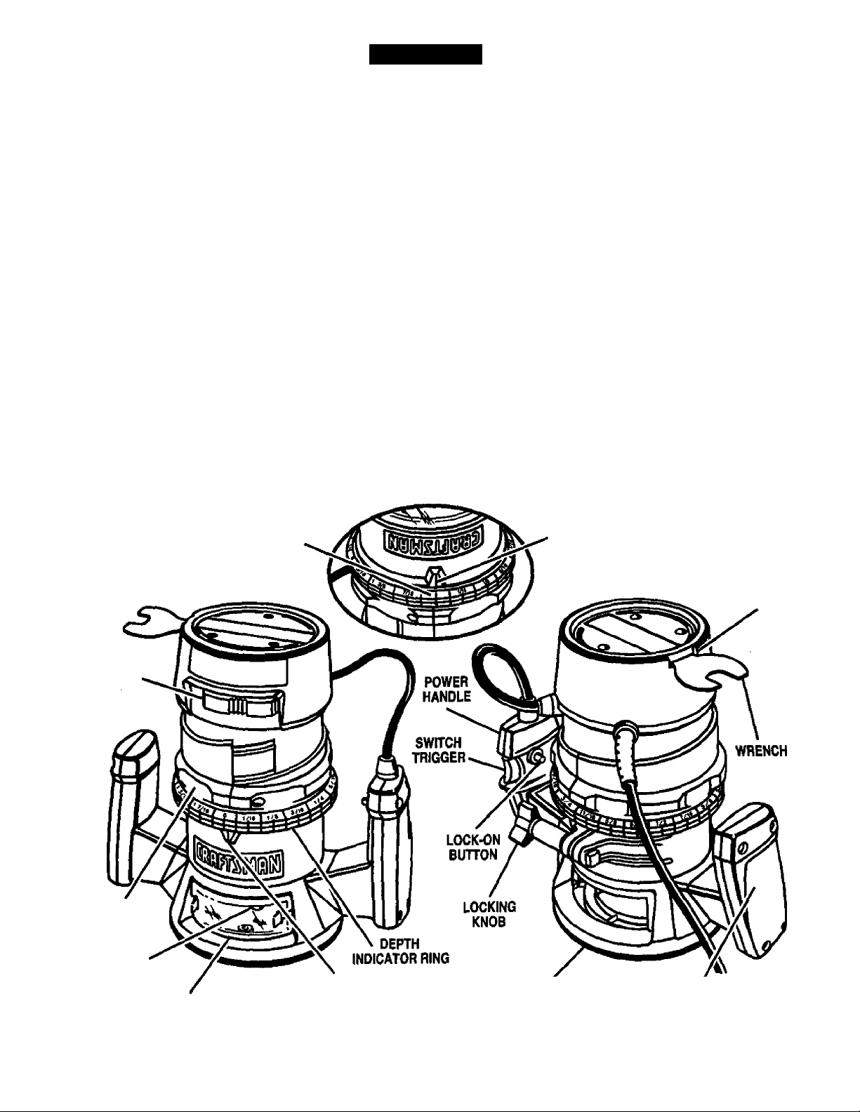
FEATURES
KNOW YOUR ROUTER
See Figure 1.
Before attempting to use any tool, familiarize yourself
with all operating features and safety requirements.
SWITCH
To turn your router on, depress the switch trigger.
Release switch trigger to turn your router off.
LOCK-ON BUTTON
The switch of your router is equipped with a iock-on
feature which is convenient when operating for
extended periods of time. To lock on, depress the
trigger, push in the lock button located on the side of
the handle, then while holding the lock button pushed
in, release the trigger. To release the lock, depress
the trigger and release.
CHIP SHIELD
A clear plastic chip shield is installed on the front of
your router for protection against flying dust and
chips. The shield is designed to fit the front opening of
the router base. If necessary to remove chip shield,
UPSIDE DOWN VIEW OF ROUTER
squeeze the tabs on each end and pull outward. To
replace, squeeze the tabs at each end, fit into
opening, then release. For your protection, do not
use router without chip shield properly In place.
WRENCH STORAGE AREA
Your router has a wrench storage area located on the
top end cap portion of the motor housing. When
installing or removing cutters, remove the wrench
from its storage area. Proper storage of wrench when
not in use will help reduce the possibility of losing
wrench.
ELECTRICAL CONNECTION
Your router has a precision built electric motor. It
should be connected to a power supply that Is 120
volts, 60 Hz, AC only (normal household current).
Do not operate this tool on direct current (DC). A
substantial voltage drop will cause a loss of power
and the motor will overheat. If your router does not
operate when plugged into an outlet, double-check
the power supply.
SPINDLE
LOCK
DEPTH
ADJUSTING
RING
DEPTH
INDICATOR
RING
INDICATOR
POINT
WRENCH
STORAGE
AREA
COLLET NUT
INDICATOR
CHIP SHIELD
A WARNING; Do not allow familiarity with your router to make you careless. Remember that a caret ess fraction
of a second is sufficient to inflict severe injury.
POINT
SUBBASE
HANDLE Fig. 1
Page 7

ADJUSTMENTS
A WARNING: Your router should never be
connected to power supply when you are
assembling parts, making adjustments,
installing or removing cutters, cleaning,
or when not in use. Disconnecting router
will prevent accidental starting that could
cause serious personal injury.
INSTALLING/REMOVING CUTTERS
See Figures 2 and 3.
■ Unplug your router.
WARNING: Failure to unplug your router could
result in accidental starting causing serious
injury.
■ A spindle lock is located on the front of the motor
housing. To activate lock, push spindle lock in and
slide into lock position. See Figure 2.
A WARNING; To prevent damage to the spindle
or spindle lock, always allow motor to come to a
complete stop before engaging spindle lock.
SPINDLE LOCK
CUTTER
WRENCH
COLLET
NUT
^ WARNING: If you are changing a cutter
" immediately after use, be careful not to touch the
cutter or collet with your hands or fingers. They
will get burned because of the heat buildup from
cutting. Always use the wrench provided.
Fig.3
Fig. 2
■ Place your router upside down on table, then turn
collet nut with wrench until lock mechanism
interlocks. See Figure 3.
Note; Spindle lock is spring loaded and will snap into
position when lock mechanism interlocks.
Remove cutters by turning collet nut counter
clockwise enough to allow cutter to slip easily from
collet. See Figure 3. The collet is machined to
precision tolerances to fit cutters with 1/4 in.
diameter shanks.
With your router still upside down on table, insert
shank of cutter into collet. The shank of your cutter
should be close to but not touching bottom of
collet.
Tighten the collet nut securely by turning clockwise
with the wrench provided. See Figure 3. Push
spindle lock in and slide into unlock position.
Otherwise, the interlocking mechanism of the
spindle lock will not let you turn your router on.
L WARNING: Do not use cutters with undersized
* shanks. Undersized shanks will not tighten
properly and could be thrown from tool causing
injury.
Page 8

ADJUSTMENTS
DEPTH OF CUT ADJUSTMENTS
See Figures 4, 5, and 6.
We recommend that cuts be made at a depth not
exceeding 1/8 in. and that several passes be made to
reach depths of cut greater than 1/8 in.
■ Unplug your router.
iV WARNING: Failure to unplug your router could
result in accidental starting causing
serious injury.
■ Place your router on a flat surface, loosen locking
knob, and turn depth adjusting ring until cutter is
inside subbase. See Figure 4.
TO
TIGHTEN
LOCKING
KNOB
TO
LOOSEN
CUHERATZERO
DEPTH OF CUT
Position your router so that the cutter can extend
below the subbase for desired depth setting.
See Figure 6.
Fig. 5
DEPTH
ADJUSTING
RING
DEPTH
INDICATOR
RING
INDICATOR
CUTTER
INSIDE SUBBASE
POINT
SUBBASE Fig. 4
Turn depth adjusting ring until tip of cutter touches
flat surface. Turn the depth indicator ring until the
zero lines up with the indicator point on the base.
Note: The depth indicator ring is also a zero reset
indicator when setting cutter at zero depth of cut,
then it becomes the depth adjusting ring.
See Figure 5.
CUHER EXTENDED
BELOW SUBBASE
Fig. 6
Turn the depth adjusting ring to obtain the desired
depth of cut. The distance the cutter moves can be
read on the depth adjusting ring. Each mark on the
depth adjusting ring indicates 1/16 inch change in
depth setting. Indicator point is located on the
base.
Tighten locking knob securely before operating
router.
Page 9

ADJUSTMENTS
OPERATION
DEPTH OF CUT ADJUSTMENTS WHEN
ROUTER IS MOUNTED TO A ROUTER TABLE
See Figure 7.
The depth of cut is readable from both sides of the depth
indicator ring. The bottom ring is convenient when using
your router mounted upside down to a router table. The
indicator point on the base can also be used when using
your router mounted to a router table.
Set the cutter at zero depth of cut, rotate depth
indicator ring to desired depth of cut on the scale,
then tighten locking knob securely.
FOR ROUTER TABLE USE ONLY
INDICATOR
POINT
DEPTH
INDICATOR RING
Fig. 7
ROUTER TABLES
The use of Craftsman routers on router tables offered
by other manufacturers has not been investigated for
compliance with applicable safety standards.
WARNING: Do not use with router tables that
fail to conform to safe wood working practices
and offer proper guarding for the cutter. Failure
to comply can result in an accident causing
possible serious injury.
HELPFUL HINTS
/ Always clamp workpiece securely before routing.
/ A safe operator is one who thinks ahead.
/ Always wear eye protection when routing.
✓ Make setup adjustments carefully. Then double
check. Measure twice and cut once.
✓ Keep cutters clean and properly sharpened.
/ Don’t let familiarity make you careless.
/ Study all safely rules and do the job safely.
✓ Never place your hands in jeopardy.
✓ Make certain clamps can’t loosen while in use.
/ Test difficult setups on scrap — Don’t waste
lumber.
/ Plan each operation before you begin.
</ Provide for smoother operation by cleaning your
router frequently. Shake router or blow with an air
jet to remove sawdust buildup.
/ Think safety by thinking ahead.
ROUTING
See Figure 6.
For ease of operation and maintaining proper control,
your router has two handles, one on each side of the
router base. When using your router hold it firmly with
both hands as shown in Figure 8.
Turn router on and let motor build to its full speed,
then gradually feed cutter into workpiece. Remain
alert and watch what you are doing. Do not operate
router when fatigued.
HANDLE
POWER
HANDLE
PRACTICE BEFORE ACTUAL USE
We suggest that you practice with your router before
installing a cutter and making cuts in wood. Check
the following before connecting your router to
power supply.
■ Make sure power supply Is 120 volts, 60 Hz, AC
only.
■ Make sure the spindle lock is in the unlocked
position.
■ Make sure the trigger is not in the lock-on position.
■ Make sure there is not a cutter in the collet.
■ Make sure the collet does not extend below the
subbase.
■ Plug your router into power supply.
■ Grasp your router firmly with both hands and turn on.
Fig. 8
WARNING: Keep a firm grip on router with both
hands at all times. Failure to do so could result in
loss of control leading to possible serious injury.
Page 10

OPERATION
FREEHAND ROUTING
See Figure 9.
FREEHAND ROUTING
Fig. 9
When used freehand, your router becomes a flexible
and versatile tool. This flexibility makes it possible to
easily rout signs, relief sculptures, etc.
There are two basic techniques
for freehand routing;
■ Routing letters, grooves, and patterns into wood.
See Figure 9.
■ Routing out the background, leaving the letters
or pattern raised above the surface.
When freehand routing, we suggest the following:
■ Draw or layout the pattern on workpiece.
■ Choose the appropriate cutter.
Note: A core box or V-groove bit is often used for
routing letters and engraving objects. Straight bits
and ball mills are often used to make relief
carvings. Veining bits are used to carve small,
intricate details.
■ Rout the pattern in two or more passes. Make the
first pass at 25% of the desired depth of cut. This
will provide better control as well as being a guide
for the next pass.
■ Do not rout deeper than 1/8 in. per pass or cut.
Vi WARNING: Do not use large router bits for
freehand routing. Use of large router bits when
freehand routing could cause loss of control or
create other hazardous conditions that could
cause possible serious personal injury. When
using a router table, large router bits should be
used for edging only. Do not use router bits that
are larger in diameter than the opening in router
base for any purpose.
RATE OF FEED
IMPORTANT: The whole “secret" of professional
routing and edge shaping lies in making a careful
setup for the cut to be made and in selecting the
proper rate of feed.
PROPER FEEDING
The right feed is neither too fast nor too slow. It is the
rate at which the bit is being advanced firmly and
surely to produce a continuous spiral of uniform chips
— without hogging into the wood to make large
individual chips or, on the other hand, to create only
sawdust. If you are making a small diameter, shallow
groove in soft, dry wood, the proper feed may be
about as fast as you can travel your router along your
guide line. On the other hand, if the bit is a large one,
the cut is deep or the wood is hard to cut, the proper
feed may be a very slow one. A cross-grain cut may
require a slower pace than an identical with grain cut
in the same workpiece.
There is no fixed rule. You will learn by experience
from practice and use. The best rate of teed is
determined by listening to the sound of the router
motor and by feeling the progress of each cut. Always
test a cut on a scrap piece of the workpiece wood,
beforehand.
FORCE FEEDING
Clean, smooth routing and edge shaping can be done
only when the bit is revolving at a relatively high
speed and is taking very small bites to produce tiny,
cleanly severed chips. If your router is forced to move
forward too fast, the RPM of the bit becomes slower
than normal in relation to its forward movement. As a
result, the bit must take bigger bites as it revolves.
“Bigger bites” mean bigger chips, and a rougher
finish. Bigger chips also require more power, which
could result in the router motor becoming overloaded.
Under extreme force-feeding conditions the relative
RPM of the bit can become so stow — and the bites it
has to take so large — that chips will be partially
knocked off (rather than fully cut off), with resulting
splintering and gouging of the workpiece.
See Figure 10.
10
Page 11

OPERATION
TOO FAST
TOO SLOW
Fig. 10
Your router is an extremely high-speed tool (25,000
RPM no-load speed), and will make clean, smooth
cuts if allowed to run freely without the overload of a
forced (too fast) feed. Three things that cause lorce
feeding” are bit size, depth-of-cut, and workpiece
characteristics. The larger the bit or the deeper the
cut, the more slowly the router should be moved
fonvard. If the wood is very hard, knotty, gummy or
damp, the operation must be slowed still more.
You can always detect “force feeding” by the sound of
the motor. Its high-pitched whine will sound lower and
stronger as it loses speed. Also, the strain of holding
the tool will be noticeably increased.
TOO SLOW FEEDING
It is also possible to spoil a cut by moving the router
forward too slowly. When it is advanced into the work
too slowly, a revolving bit does not dig into new wood
fast enough to take a bite; instead, it simply scrapes
away sawdust-like particles. Scraping produces heat,
which can glaze, bum, or mar the cut — in extreme
cases, can even overheat the bit so as to destroy its
hardness.
In addition, it is more difficult to control a router virhen
the bit is scraping instead of cutting. With practically
no load on the motor the bit will be revolving at close
to top RPM, and will have a much greater than normal
tendency to bounce off the sides of the cut (especially
if the wood has a pronounced grain with hard and soft
areas). As a result, the cut produced may have
rippled, instead of straight sides. See Figure 10.
Too-slow feeding" can also cause your router to take
off in a wrong direction from the intended line of cut.
Always grasp and hold your router firmly with
both hands when routing.
You can detect “too-slow feeding" by the runaway
too-highiy pitched sound of the motor; or by feeling
the “wiggle” of the bit in the cut.
DEPTH OF CUT
As previously mentioned, the depth of cut is important
because it affects the rate of feed which, in turn,
affects the quality of a cut (and, also, the possibility of
damage to your router motor and bit). A deep cut
requires a slower feed than a shallow one, and a too
deep cut will cause you to slow the feed so much that
the bit is no longer cutting, it is scraping, instead .
Making a deep cut is never advisable. The smaller
bits —especially those only 1/16 inch in diameter —
are easily broken off when subjected to too much side
thrust. A targe enough bit may not be broken off, but if
the cut is too deep a rough cut will result — and it may
be very difficult to guide and control the bit as desired.
For these reasons, we recommend that you do not
exceed 1/8 inch depth of cut in a single pass,
regardless of the bit size or the softness or condition
of the workpiece. See Figure 11.
11
Page 12

OPERATION
To make deeper cuts it is therefore necessary to
make as many successive passes as required,
iowering the bit 1/8 inch for each new pass. In order to
save time, do all the cutting necessary at one depth
setting, before lowering the bit for the next pass. This
wilt also assure a uniform depth when the final pass is
completed. See Figure 12.
2ND. PASS
Fig. 12
DIRECTION OF FEED AND THRUST
The router motor and bit revoive in a clockwise direc
tion. This gives the tooi a slight tendency to twist (in
your hands) in a counterclockwise direction, especially
when the motor revs up (as at starting).
Because of the extremely high speed of bit rotation
during a “proper feeding” operation, there is very little
kickback to contend with under normai conditions.
However, should the bit strike a knot, hard grain,
foreign object, etc. that would affect the normal
progress of the cutting action, there will be a slight
kickback — sufficient to spoil the trueness of your cut if
you are not prepared. Such a kickback is always in the
direction opposite to the direction of bit rotation.
To guard against such a kickback, plan your setup and
direction of feed so that you wili always be thrusting
the tool — to hold it against whatever you are using to
guide the cut — in the same direction that the leading
edge of the bit is moving. In short, the thrust should be
in a direction that keeps the sharp edges of the bit
continuously biting straight into new (uncut) wood.
ROUTING
Whenever you are routing a groove, your travel
should be in a direction that places whatever guide
you are using at the right-hand side. In short, when
the guide is positioned as shown in the first part of
Figure 13, tool travel should be left to right and
counterclockwise around curves. When the guide is
positioned as shown in the second part of Figure 13,
tool travel should be right to left and clockwise around
curves. If there is a choice, the first setup is generally
the easiest to use. In either case, the sideways thrust
you use is against the guide.
GUIDE OUTSIDE
GUIDE FEED
GUIDE INSIDE
THRUST
Fig. 13
12
Page 13

OPERATION
STARTING AND ENDING A CUT
INTERNAL ROUTING
Tilt router and place on workpiece, letting edge of
subbase contact workpiece first. Be careful not to let
router bit contact worl^iece. Turn router on and let
motor build to its full speed. Gradually feed cutter into
workpiece until subbase is ievei with workpiece.
VI WARNING: Keep a firm grip on router with both
hands at all times. Failure to do so could result in
loss of control leading to possible serious injury.
Upon completion of cut, turn motor off and iet it come
to a complete stop before removing router from work
surface.
VV WARNING: Never pull router out of work and
place upside down on work surface before the
cutter stops.
EDGING WITH PILOT BITS
See Figure 14.
Whenever the workpiece thickness together with the
desired depth of cut (as adjusted by router depth
setting) are such that only the top part of the edge is
to be shaped (leaving at least a 1/16 inch thick uncut
portion at bottom), the pilot can ride against the uncut
portion, which will serve to guide it. See Figure 14.
However, if the workpiece Is too thin or the bit set too
low so that there will be no uncut edge to ride the pilot
against, an extra board to act as a guide must be
placed under the workpiece. This “guide” board must
have exactiy the same contour — straight or curved
— as the workpiece edge, if it is positioned so that its
edge is flush with the workpiece edge, the bit will
make a full cut (in as far as the bit radius). On the
other hand, if the guide is positioned as shown in
Figure 14 (out from the workpiece edge), the bit will
make less than a full cut —; which wili alter the shape
of the finished edge.
Note: Any of the piloted bits can be used without a
pilot for edge shaping with guides, as preceding. The
size (diameter) of the pilot that is used determines the
maximum cut width that can be made with the pilot
against the workpiece edge - the small pilot exposes
all of the bit; the large one reduces this amount by
1/16 inch.
TOP EDGE SHAPING
GUIDE
PILOT
WHOLE EDGE SHAPING
Fig. 14
Arbor-type bits with pilots are excellent for quick,
easy, edge shaping. They will follow workpiece edges
that are either straight or curved. The pilot prevents
the bit from making too deep a cut; and holding the
pilot firmly in contact with the workpiece edge
throughout prevents the cut from becoming too
shallow.
EDGE ROUTING
Piace router on workpiece, making sure the router bit
does not contact workpiece. Turn router on and let
motor build to its full speed. Begin your cut, gradually
feeding cutter into workpiece.
WARNING: Keep a firm grip on router with both
hands at all times. Failure to do so could result in
loss of control leading to possible serious injury.
Upon completion of cut, turn motor off and let it come
to a complete stop before removing router from work
surface.
VV WARNING: Never puli router out of work and
place upside down on work surface before the
cutter stops.
ROUTING WITH GUIDE BUSHINGS
When using the Template Guide Bushings Item No.
S-25082 with your router, you must visually center the
bit with the bushing before beginning your cut. Your
router subbase may be adjusted by loosening the
screws holding the subbase to your router. Be sure
iocking knob is tightened before centering bit in
bushing. After centering bit with bushing, tighten
screws securely.
13
Page 14

MAINTENANCE
^ WARNING: When servicing, use only identical
Craftsman replacement parts. Use of any other
part may create a hazard or cause product
damage.
GENERAL
Only the parts shown on parts list, page 17, are
intended to be repaired or replaced by the customer.
All other parts represent an important part of the
double insulation system and should be serviced only
by a qualified Sears service technician.
Avoid using solvents when cleaning plastic parts.
Most plastics are susceptible to damage from various
types of commercial solvents and may be damaged
by their use. Use clean cloths to remove dirt, carbon
dust, etc.
WARNING: Do not at any time let brake fluids,
gasoline, petroleum-based products, penetrating
oils, etc. come in contact with plastic parts. They
contain chemicals that can damage, weaken or
destroy plastic.
It has been found that electric tools are subject to
accelerated wear and possible premature failure when
they are used on fiberglass boats, sports cars,
watiboard, spackling compounds, or plaster. The
chips and grindings from these materials are highly
abrasive to electric tool parts such as bearings,
brushes, commutators, etc. Consequently, it is not
recommended that this tool be used for extended
work on any fiberglass material, wallboard, spackling
compounds, or plaster. During any use on these
materials it is extremely important that the tool is
cleaned frequently by blowing with an air jet.
LUBRICATION
All of the bearings in this tool are lubricated with a
sufficient amount of high grade lubricant for the life of
the unit under normal operating conditions. Therefore,
no further lubrication is required.
EXTENSION CORDS
The use of any extension cord will cause some loss of
power. To keep the loss to a minimum and to prevent
tool overheating, use an extension cord that is heavy
enough to carry the current the tool will draw.
A wire gage size (A.W.G.) of at least 14 is
recommended for an extension cord 100 feet or less
in iength. When working outdoors, use an extension
cord that is suitable for outdoor use. The cord's jacket
will be marked WA.
CAUTION: Keep extension cords away from the
cutting area and position the cord so that it will
not get caught on lumber, tools, etc., during
cutting operation.
WARNING: Check extension cords before each
use. If damaged replace immediately. Never use
tool with a damaged cord since touching the
damaged area could cause electrical shock
resulting in serious injury.
Extension cords suitable for use with your router are
available at your nearest Sears Retail Store.
WARNING: Always wear safety goggles or
safety glasses with side shields during power
tool operation or when blowing dust, if operation
is dusty, also wear a dust mask.
PROPER CARE OF CUTTERS
Get faster more accurate cutting results by keeping
cutters clean and sharp. Remove all accumulated
pitch and gum from cutters after each use.
When sharpening cutters, sharpen only the inside of
the cutting edge. Never grind the outside diameter. Be
sure when sharpening the end of a cutter to grind the
clearance angle the same as originally ground.
PROPER CARE OF COLLET
From time to time, it also becomes necessary to clean
your collet and collet nut. To do so, simply remove
collet nut from collet and clean the dust and chips that
have collected. Then return collet nut to its original
position.
14
Page 15

MAINTENANCE
SWITCH REPLACEMENT
See Figures 15 and 16.
■ Unplug your router.
WARNING: Failure to unplug your router could
result in accidental starting causing
serious injury.
■ Remove screws (A) and handle cover (B).
See Figure 15.
■ Make lead connections to new switch. Push each
lead as far as possible into proper switch
receptacle. Puli on leads to check lead connections
with lead receptacles.
■ Locate switch in handle and place leads so they
woni be pinched or contact screws when handle
cover is replaced.
■ Make sure molded bend relief (C) is correctly
positioned in switch handle, then replace handle
cover and screws.
■ Tighten all screws securely.
LIGHT BULB REPLACEMENT
See Figure 17.
■ Unplug your router.
A WARNING: Failure to unplug your router could
result in accidental starting causing serious
injury.
■ Remove cutter from router. Refer to page 7 to
remove cutter.
■ Adjust router to maximum height.
■ Remove screws (A) and subbase (B).
See Figure 17.
Note the location of the molded bend relief (C)
on the power handle cord. Also note ail wiring
in the handie and how each lead is connected
to the switch. Connections and wiling position
must be identical when installing new switch.
See Figure 15.
Remove leads from switch (D) by inserting a 1/32
in. diameter nail or pin into switch lead receptacle
and pulling on lead as shown in Figure 16.
Remove nail or pin with a twisting, pulling motion.
LEAD
POWER
HANDLE
CORD
BLACK
WORK
UGHT
SWITCH
With bulb (E) pointing toward you, push bulb in and
turn to the left to remove from bulb socket.
Note; Light butb removal and installation is similar
to removing and installing a standard automotive
bulb.
Install new bulb by reversing the above procedure.
Reassemble all parts and tighten screws securely.
Fig. 16
15
Page 16

CRAFTSMAN ROUTER - MODEL NUMBER 315.175000
NOTE: "A" - The assembly shown represents an Important part of the Double Insulated System, To avoid
the possibility of alteration or damage to the System, service should be performed by your nearest
Sears Repair Center. Contact your nearest Sears Retail Store for Service Center Information.
16
Page 17

CRAFTSMAN ROUTER - MODEL NUMBER 315.175000
The model number will be found on a plate attached to the motor housing. Always mention the model number
in aii correspondence regarding your ROUTER or when ordering repair parts.
SEE BACK PAGE FOR PARTS ORDERING INSTRUCTIONS
PARTS LIST
Key Part
No.
1
2
3
4
5
6
7
8
9
10
11
12
13
14
15
16
17
18
19
20
21
22
23
24
25
26
27
Number
981575-001
970692-001
981576-001
989985-003
974722-000
974131-001
623166-006
622832-014
606066-004
617966-030
970697-000
973735-206
606688-002
998586-001
612191-004
989684-001
975041-001
610930-001
970696-000
610951-001
998895-001
999603-001
931744-059
623173-006
999053-003
989935-006
981574-000
972000-673
Description
Data Plate..........................................................................
Label...............................................................................
Logo Plate.......................................................................
Collet Nut {1/4 in.)...............................................................
Depth Adjusting Ring Assembly (Includes Key No. 25)
Depth Indicator Ring
* Square Head Bolt (#1/4-20 x 1-1/4 in.)....................................
Roll Pin.......................................................................
* Screw (#10-32 X 3/4 in. Pan Hd.)...........................................
* Screw (#8-10 X 5/8 in. Pan Hd.).............................................
Handle Assembly
Base..........................................................................
Chip Shield.....................................................................
* Screw (#10-32 X 1/4 in. Pan Hd.)
Subbase ......................................................................
* Screw (#6-32 X1/4 in. T. C. Pan Hd.)......................................
Work Light Lens..................................................................
Light Housing
Power Handle Assembly
Light Buib
Switch................................................................................
Knob.....................................................................
Washer..............................................................................
Wire Nut.............................................................................
* Screw (#5-10 X 1/2 in. Fil. Hd.)
Wrench (9/16 in.).................................................................
Carrying Case - Not Shown..................................................
Owner's Manuai
...............
...........................................................
...............................................................
...........................................
....................................................................
.....................................................
............................................................
...............................................
...........
Quan.
..............
..............
..............
..............
1
1
3
1
Standard Hardware Item - May Be Purchased Locally
17
Page 18

In U.S.A. or Canada
for in-home major brand repair service:
Call 24 hours a day, 7 days a week
1-800-4-MY-HOME" (1-800-469-4663)
Para pedir servicio de reparación a domicilio -1-800-676-5811
Au Canada pour tout le service ou les pièces - 1-800-469 4663
For the repair or replacement parts you need:
Call 6 a.m. - 11 p.m. CST, 7 days a week
SM
Parts Direct
1-800-366-PART (1-800-366-7278)
Para ordenar piezas con entrega a domiciiio - 1-800-659-7084
For the iocation of a Sears Service Center in your area:
Call 24 hours a day, 7 days a week
1-800-488-1222
To purchase or inquire about a Sears Maintenance Agreement:
Call 7 a.m. - 5 p.m. CST, Monday - Saturday
1-800-827-6655
Page 19

BILLING SHEET AND I^CE INFORMATION FOR:
CRAFTSMAN ROUTER
MODEL NO. 175000
KEY PART NO.
1 981575-001
2 970692-001
3
981576-001
4
989985-003
S
974722-000
6
974131-001
7
623166-006
8 622832-014
9 606066-004
10
617966-030
11
970697-000
12
973735-206
13 606688-002
14
998586-001
IS 612191-004
16 989684-001
17
975041-001 WORK LIGHT LENS 7 81
18
610930-001
19
970696-000
20 610951-001
21
998895-001
22 999603-001
23
931744-059
24
623173-006
25
999053-003
26
989935-006
27
981574-000
DESCRIPTION
DATA PLATE
LABEL
LOGO PLATE
COLLET NUT (1/4”)
DEPTH ADJUSTING
RING ASSY. KVCL.
KEY 25
DEPTH INDICATOR
RING
‘SQUARE HEAD BOLT
(#1/4-20 X1-1/4”)
ROLL PIN
‘SCREW (#10-32 Xy*”
PAN HD)
‘SCREW (#8-10 X 5/8”
P/WHD)
HANDLE ASSEMBLY
BASE
CHIP SHIELD
‘SCREW (10-32 X W”
PD HD)
SUBBASE
‘SCREW (#6-32 X W”
T.C. PAN HD)
LIGHT HOUSING
POWER HANDLE
/(SSSY.
LIGHT BULB
SWITCH
KNOB
washer ..............................
WIRE NUT
•SCREW (5-10 X W”
FIL. HD.)
WRENCH 9/16”
CARRYING CASE
(NOT SHOWN)
BUYER P/C
7
7
7
81
81
81
7 81
7
81
7 81
7
7
81
81
7 81
7
81
7 81
7 81
7
7
81
81
7 81
7
81
7 81
7
7
7
81
81
81
7 81
7
7
7
7
8l
81
81
81
7 81
BILLING
COST
SELLING
COST
ifc • -s
T-
O.B
U.B
BASE
COST
.00
.00
.00
.00
.00
.00
.00
.00
.00
.00
.00
.00
.00
.00
.00
.00
.00
.00
.00 31
.00
.00 2.17
.00
2.67
.00 .15
.00 .15
.00
.00 .15
.00 1.02
.00 15.93
.00 .25
.00 .15
.00 .74
.00 .15
.00 .00
.00
.00
.00
.00 .67
.00 1.09
.00 37
.00 .00 135
.00
.00
.00
.00 .55
.00 .15
.00 .15
.00 .00 .15
.00 .00 .62
.00
.00 9.10
ORDER
POINT
.15
.15
30
.15
.50
* STANDARD HARDWARE ITEM - MAY BE PURCHASED LOCALLY
Page 20

BILLING SHEET AND PRICE INFORMATION FOR:
KEY
10 610784-048
11
12 616081-014
13 612848-007
14 974951-001
15 989573-001 RETAINER CLIP
16 971669-002
17 970794^)05
18 980826-001
19 968843-002 ARMATURE
20 622167-012
21
22 973739-001
PART NO.
I
989592-002 •SCREW #8-10 X 1-3/8”
2 970502-007 END CAP
3
617834-001 BUMPER
4
623173-006 WIRE NUT
5 970777-002
6
973738-001 LOCK BUTTON
7
612858-001 SLIDE ASSEMBLY
8 612856-002
9 989^29-001
611686-003 BRUSH TUBE
989919-004
972000-673
DESCRIPTION BUYER
FIL.HD.)
CORD ASSEMBLY 7
SWITCH
•SCREW (#10-16 X1”
PAN HD. T.F.)
BRUSH ASSEMBLY 7 81
•SCREW (8-18 X11/16"
PAN HD.T.C.
TOP BEARING PLATE 7
COMPRESSION
SPRING
POWER HANDLE
CORD
FIELD ASSEMBLY 7 81
BALL BEARING (NSK
608VV)
RETAINING RING 7 81
BALL BEARING (NTN
#6001LLUC3/1E)
MOTOR HOUSING 7
OWNERS MANUAL
CRAFTSMAN ROUTER
MODEL NO. 1750Q0
P/C BILLING
7 81
7 81
7 81 .00
7 81
7 81 .00
7 81
7 81
7 81
7 81
7
7
7 81
7 81
81
81
81
81 .00
7 81
7 81
7 81
81 .00 .00 3.46
7 81
*
COST
SELLING
COST
O.B
.00 .00
.00 .00
.00 .00'
.00 .00
.00 .00
.00 .00
.00
.00
.00 .00
.00 .00 .15
.00 .00 3.06
.00 .00 .15
.00
.00 .00 4.21
.00 .00 1.08
.00 .00 5.47
.00 .00 .15
.00 .00 1.65
.00 .00 .50
U.B BASE
COST
.15
.00
.00
.00 .15
.00 .22
.00 .15
.00
1.49
.15
.15
2.71
2.02
ORDER
POINT
.36
J6
.56
.15
* STANDARD HARDWARE ITEM - MAY BE PURCHASED LOCALLY
 Loading...