

Craftsman 31517500 Owner’s Manual
ISears I
OWNERS
MANUAL
MODEL NO
315.17500
CAUTION:
Read Rules for
Safe Operation
and Instructions
Careft_lly
SAVE THIS
MANUAL FOR
FUTURE REFERENCE
CRAFTSMAN
ELECTRONIC
ROUTER
DOUBLE INSULATED
Introduction
Operation
Maintenance
Repair Parts
Designed exclusively for and sold only by
SEARS, ROEBUCK AND CO., Dept. 698/731A, Sears Tower, Chicago, IL 60684
612547-213 PRfNTEtj (N U.S.A.
4.64
®
FULL ONE YEAR WARRANTY ON CRAFTSMAN ELECTRONIC ROUTER
If this Craftsman Electronic Router fails to give complete satisfaction within one year from the date
of purchase, RETURN IT TO THE NEAREST SEARS STORE THROUGHOUT THE UNITED STATES
and Sears will repair it, free of charge.
If this router is used for commercial or rental purposes this warranty applies for only 90 days from the
date of purchase.
This warranty gives you specific legal rights, and you may also have other rights which vary from
state to state.
SEARS, ROEBUCK AND CO.
DEPT. 698/731A
SEARS TOWER
CHICAGO, IL 60684
INTRODUCTION
DOUBLE INSULATION Is a concept in safety, In elec-
trlc power tools, which eliminates the need for the
usual three wire grounded power cord and grounded
sup_)ly system. Wherever there is electric current in
the tool there are two complete sets of insulation to
protect the user. All exposed metal parts are isolated
from the internal metal motor components with pro-
tecting Insulation.
GENERAL
Your electronic router is a versatile woodworking
tool which will give you years of trouble-free perfor-
mance. It is engineered with the professional in
mind, but its ease of operation allows the amateur to
produce work which is beautiful and precise. Your
new router has advanced electronic features which
are designed to assist you In getting the maximum
use from your router. By making "the proper selec-
tions on the front panel, your router can be adjusted
to your specific routing needs. This eliminates much
of the guess work previously needed to perform a
glven job. Both the experienced and inexperienced
router users benefit, obtaining professional like
results with fewer job errors.
The electronic feature of your router introduces the
flexibility of adjusting the motor speed to the re-
quired job Conditions. The front panel can be set ac-
cording to the approximate cutter diameter you will
be using and to the hardness of the material being
cut. Your router will then run smoothly up to the
RULES FOR SAFE OPERATION
WARNING -- DO NOT ATrEMPT TO OPERATE UNTIL YOU HAVE READ THOROUGHLY AND UNDERSTAND
COMPLETELY ALL INSTRUCTIONS, RULES, ETC. CONTAINED IN THIS MANUAL. FAILURE TO COMPLY CAN
RESULT IN ACCIDENTS INVOLVING FIRE, ELECTRIC SHOCK, OR SERIOUS PERSONAL INJURY. SAVE
OWNERS MANUAL AND REVIEW FREQUENTLY FOR CONTINUING SAFE OPERATION, AND INSTRUCTING
POSSIBLE THIRD.PARTY USER.
IMPORTANT -- Servicing of a tool with double in-
sulatlon requires extreme care and knowledge of the
system and should be performed only by a qualified
service technician. For service we suggest you
return the tool to your nearest Sears Store for repair.
Always use original factory replacement parts when
servicing.
desired speed and continue to maintain this speed
while under various loads.
Also, the best cuts are made when the cutter is fed
through the material at the proper rate. Your elec-
tronic router has "too slow" and "too fast" In-
dicators that will flash if the cutter is being fed too
slow or too fast. When possible, you should make
practice cuts on a scrap piece of wood to get a
"feel" of how fast to "feed" your router.
If your router should become overloaded or jammed,
then both the "too stow'" and "too fast" indicator
lights will begin flashing. If the overload condition Is
not corrected, your router will shut off. This helps
prevent the possibility of damage to the router. To
restart, release the trigger switch to its full "off"
position, wait until the indicator lights stop flashing,
then turn your router on. WARNING: DO NOT
OVERLOAD YOUR ROUTER REPEATEDLY. ABUSE
OF THIS NATURE WILL GREATLY REDUCE THE
LIFE OF YOUR ROUTER.
READ ALL INSTRUCTIONS
1. KNOW YOUR POWER TOOL -- Read owner's manual carefully, Learn its ap-
pllcatlons and limitations as well as the specific potential hazards peculiar to
this tool.
2. GUARD AGAINST ELECTRICAL SHOCK BY PREVENTING BODY CONTACT
WITH GROUNDED SURFACES. For example: Pipes, radiators, ranges, refrig-
erator enclosures.
3. KEEP GUARDS IN PLACE and in working order.
4. KEEP WORK AREA CLEAN. Cluttered areas and benches invite accidents.
5. AVOID DANGEROUS ENVIRONMENT. Don't useiP°werIt, tool in clamp or wet
locations or expose to rain. Keep work area well .
Page 2
RULES FOR SAFE OPERATION (Continued)
6. KEEP CHILDREN AWAY. All visitors should be kept safe distance from work
area. Do not let visitors contact tool or extension cord.
7. STORE IDLE TOOLS. When not In use, tools should be stored in dry, high or
locked-up place -- out of reach of children.
8. DON'T FORCE TOOL. It will do the job better and safer at the rate for which it
was designed.
9. USE RIGHT TOOL. Don't force small tool or attachment to do the job of a heavy
duty tool. Don't use tool for purpose not intended - for example - Don't usa
a circular saw for cutting tree limbs or logs.
10. WEAR PROPER APPAREL. No loose clothing or jewelry to get caught in moving
parts. Rubber gloves and footwear are recommended when working outdoors.
Also, wear protective hair covering to contain long hair.
11. USE SAFETY GLASSES with all tools. Also face or dust mask if' cutting
operation Is dusty.
12. DON'T ABUSE CORD. Never carry tool by cord or yank it to disconnect from
receptacle. Keep cord from heat, oil and sharp edges.
13. SECURE WORK. Use clamps or a vise to hold work. It's safer than using your
hand and it frees both hands to operate tool.
14. DON'T OVERREACH. Keep proper footing and balance at all times.
15. MAINTAIN TOOLS WITH CARE. Keep tools sharp at all times, and clean for best
and safest performance. Follow instructions for lubricating and changing ac-
cessories.
16. DISCONNECT TOOLS. Whennot in use, before servicing_ or when changing at-
tachments, blades, bits, cutters, etc., all tools should be disconnected.
17, REMOVE ADJUSTING KEYS AND WRENCHES. Form habit of checking to see
that keys and adjusting wrenches are removed from tool before turning it on.
18. AVOID ACCIDENTAL STARTING. Don't carry piugged-m tools with finger on
switch. Be sure switch is off whenplugging in.
19. OUTDOOR USE EXTENSION CORDS.When tool is used outdoors, use only
extension cords suitable for use outdoors, Outdoor approved cords are marked
with the suffix W-A, for example -- SJTW-A or SJOW-A.
20. KEEP CUTTERS CLEAN AND SHARP. Sharp cutters minimize stalling and kick-
back.
21. KEEP HANDS AWAY FROM CUTTING AREA. Keep hands away from cutters. Do
not reach underneath Work while cutter is rotating. Do not attempt to remove
material while cutter is rotating,
22. NEVER USE IN AN EXPLOSIVE ATMOSPHERE. Normal sparking of the motor
could ignite fumes.
23. INSPECT TOOL CORDS PERIODICALLY and if damaged, have repaired at your
nearest Sears Repair Center.
24. INSPECT EXTENSION CORDS PERIODICALLY and replace if damaged.
25. KEEP HANDLES DRY, CLEAN, AND FREE FROM OIL AND GREASE. Always
use aclean cloth when cleaning. Never use brake fluid, gasoline, or any Strong
solvents to clean your tool.
26. STAY ALERT. Watch what you are doing and use common sense. Do not op-
erate tool whenyou are tired,
27. CHECK DAMAGED PARTS. Before further use of the tool, a guard or
other part that is damaged should be carefully checked to determine that it will
operate properly and perform its intended function. Check for alignment of mov-
ing parts, binding of moving parts, breakage of parts, mounting, and any other
conditions that may affect its operahon. A guard or other part that is damaged
should be properly repaired or replaced by an authorized service center unless
indicated elsewhere In this instruction manual.
28. DO NOT USE TOOL I1=SWITCH DOES NOT TURN IT ON AND OFF. Have defect-
ire switches replaced by authorized 'service center.
29. Inspect for and remove all hails _from lumber before routitig
30. DRUGS, ALCOHOL, MEDICATION. Do not operate tool while under- the influ-
ence of drugs, alcohol, or any medication.
Page 3
-- - + ] , .u+ i1+1
nuL,-u PUR SAFE OPERATION (C0ntinu_l)
31. DO,NO, T USE TOOL UNDER ':BROWN:.0_T?_ORi_OTH_OW_vQLTAGE CON:
ul/Iu.P_. _lSO, oo not use wsth any deviC_!t'_÷('-_,l;_!_:i_-i_01wer supply
voltage to change. " ........... .......... _ "
32. SAVE THESE INSTRUCTIONS.
.... ,., ,,, - ,.. _: _: _. . . . ...
.Theoperation of any Router can result In forelg'n::Ob[eots being thrown
rote the.eyes, which can result Ih _eve_e:_;e:_ja_ge!:Alway$ wear
safety glasses or eye shields before €omh_encl_g _wer tool opera.
lion. we. recommend Wide Vlsl0n Safety maskforluse:_Vai; spectacles
or stanaara safety glasses, available at Si_al;_€_._l_g_O_derOr Retail
_tOres. ..• • "..,.,:_i.-.::_:.:_._i_i_+_!_%_!_,:y_,:... ' .
OPERATION
WARNING: YOUR ROUTER SHOULD NEVER BE PLUGGED IN WHEN YOU ARE._P_SEMBLING PARTS OR
MAKING ADJUSTMENTS. FAILURE TO DO SO COULD RESULT IN ACCIDENTAL STARTING OF YOUR
ROUTER RESULTING IN POSSIBLE SERIOUS INJURY. ALWAYS WEAR SAFF_TY :GLASSES OR
EYESHIELDS BEFORE BEGINNING POWER TOOL OPERATION.
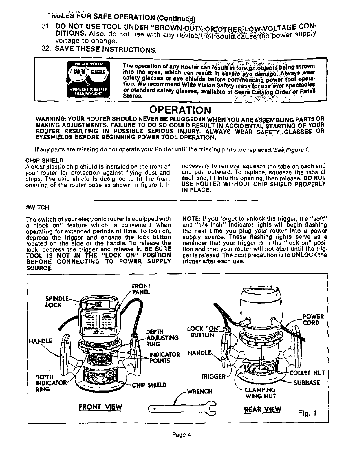
If any parts are missing do not operate your Router until the missing parts are replaced,See Figure 1.
CHIP SHIELD
A clear plastic chip shield is installed on the front of
your router for protection against flying dust and
chips. The chip shield is designed to fit the front
opening of the router base as shown in figure 1. If
necessary to remove, squeeze the tabs on each end
and pull outward. To replace, squeeze the tabs at
each end, fit Into the opening, then release. DO NOT
USE ROUTER WITHOUT CHIP SHIELD PROPERLY
IN PLACE.
SWITCH
The switch of your electronic router is equipped with
a "lock on" feature which is convenient when
operating for extended periods of time. To lock on,
depress the trigger and engage the lock button
located on the side of the handle. To release the
lock, depress the trigger and release it. BE SURE
TOOL IS NOT IN THE "LOCK ON" POBITION
BEFORE CONNECTING TO POWER SUPPLY
SOURCE.
FRONT
LOCK
DEPTH LOCK
HAHDLE
DEPTH
lUSTING BUTTON
RING
NOTE: If you forget to unlock the tdgger, the "soft"
and "1/4 Inch" Indicator lights will begin flashing
the next time you plug your router into a power
supply source. These flashing lights serve as a
reminder that your trigger is In the "lock on" posi-
tion and that your router will not start until the trig-
ger is relased. The best precaution is to UNLOCK the
trigger after each use.
POWER
_.COLLET NUT
RING
FRONT_VIEW
-CLAMPING
WING NUT
REAR VIEW
Fig. 1
Page 4
OPERATION
KNOW YOUR ELECTRONIC ROUTER
Before attempting to usa your router, familiarize
yourself with all operating features, electronic
features, and safety requirements. See Figure
/.WARNING: DO NOT ALLOW FAMILIARITY WITH
YOUR ROUTER TO MAKE YOU CARELESS.
REMEMBER THAT A CARELESS FRACTION OF A
SECOND IS SUFFICIENT TO INFLICT SEVERE IN.
JURY.
We suggest that you practice with the electronic
features of your router before installing a cutter and
making cuts in wood. CHECK THE FOLLOWING
BEFORE CONNECTING YOUR ROUTER TO POWER
SUPPLY:
1. Make sure the spindle lock is in the unlocked
position.
2. Make sure the trigger is not In the "lock on" posi-
tion.
3. Make sure there Is not a cutter In the collet.
4, Make sure the coIlet is inside the subbase.
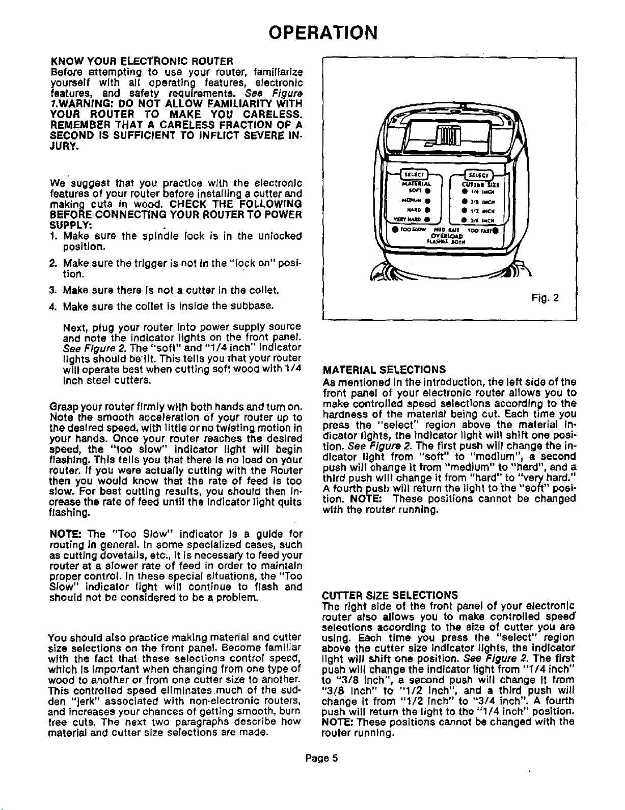
Next, plug your router into power supply source
and note the indicator lights on the front panel.
See Figure 2. The "soft" and "1/4 inch" indicator
lights should belit. This tells you that your router
will operate best when cutting soft wood with 1/4
Inch steel cutters.
Grasp your router firmly with both hands and turn on.
Note the smooth acceleration of your router up to
the desired speed, with little or no twisting motion in
your hands. Once your router reaches the desired
speed, the "too slow" indicator light will begin
flashing. This tells you that there is no load on your
router. If you were actually cutting with the Router
then you would know that the rate of feed is too
slow. For best cutting results, you should then In-
crease the rate of feed until the indicator light quits
flashing.
Fig. 2
MATERIAL SELECTIONS
As mentioned In the introduction, the left side of the
front panel of your electronic muter allows you to
make controlled speed selections according to the
hardness of the material being cut. Each time you
press the "select" region above the material In-
dicator lights, the indicator light will shift one posi-
tion. See Figure 2. The first push will change the in-
dicator light from "soft" to "medium", a second
push will change it from "medium" to "hard", and a
third push will change it from "hard" to "very hard."
A fourth push will return the light tothe "soft" posi-
tion. NOTE: These positions cannot be changed
with the router running.
NOTE: The "Too Slow" indicator Is a guide for
routing in general. In some specialized cases, such
as cutting dovetails, etc., it is necessary to feed your
router at a slower rate of feed in order to maintain
proper control. In these special situations, the "Too
Slow" indicator light will continue to flash and
should not be considered to be a problem.
You should also practice making material and cutter
size selections on the front panel. Become familiar
with the fact that these selections control speed,
which Is important when changing from one type of
wood to another or from one cutter size to another.
This controlled speed eliminates rnueh of the sud-
dan "jerk" associated with non-electronic routers,
and increases your chances of getting smooth, burn
free cuts. The next two paragraphs describe how
material and cutter size selections are made.
CUTTER SiZE SELECTIONS
The right side of the front panel of your electronic
router also allows you to make controlled speed'
selections according to the size of cutter you are
using. Each time you press the "select" region
above the cutter size Indicator lights, the indicator
light will shift one position. See Figure 2. The first
push will change the indicator light from "1/4 inch"
to "3/8 inch", a second push will change It from
"3,_8 Inch" to "1/2 inch", and a third push will
change it from "1/2 Inch" to °'3/4 inch". A fourth
push will return the light to the "1/4 inch" position.
NOTE: These positions cannot be changed with the
router running.
Page 5
 Loading...