

Page 1

PERATOR'S
MANUAL
®
T$
19,2 VOLT TRIMMER
WiTH WOODWORKING SUBBASE iNCLUDED
Model No.
315.115830
A
WARNING: To reduce the risk of injury,
the user must read and understand the
operator's manual before using this
product.
Customer Help Line: 1=800=932=3188
Sears, Roebuck and Co., 3333 Beverly Rd., Hoffman Estates, IL 60179 USA
Visit the Craftsman web page: www.sears.com/craftsman
983000-643 Save this manual for future reference
7-05
BATTERIES AND CHARGERS
SOLD SEPARATELY
C
Page 2

[] Warranty .......................................................................................................................................................................... 2
[] Introduction ..................................................................................................................................................................... 2
[] General Safety Rules .................................................................................................................................................... 3-4
[] Specific Safety Rules ....................................................................................................................................................... 4
[] Safety Rules for Charger ................................................................................................................................................. 5
[] Symbols ........................................................................................................................................................................ 6-7
[] Features ........................................................................................................................................................................ 8-9
[] Assembly .................................................................................................................................................................... 9-10
[] Operation .................................................................................................................................................................. 11-19
[] Maintenance .................................................................................................................................................................. 20
[] Exploded View and Parts List........................................................................................................................................ 21
[] Parts Ordering/Service .................................................................................................................................... Back Page
ONE YEAR FULL WARRANTY ON CRAFTSMAN TOOL
If this Craftsman tool fails to give complete satisfaction within one year from date of purchase, RETURN IT TO THE
NEAREST SEARS STORE IN THE UNITED STATES, and Sears will replace it, free of charge.
If this Craftsman tool is used for commercial or rental purposes, this warranty applies for only 90 days from the date of
purchase.
This warranty gives you specific legal rights, and you may also have other rights which vary from state to state.
Sears, Roebuck and Co., Dept. 817 WA, Hoffman Estates, IL 60179
This tool has many features for making its use more pleasant and enjoyable. Safety, performance, and dependability
have been given top priority in the design of this product making it easy to maintain and operate.
Page 3

_1=WARNING!READ AND UNDERSTAND ALL IN=
STRUCTIONS. Failure to follow all instructions listed
below may result in electric shock, fire and/or serious
personal injury.
SAVE THESE INSTRUCTIONS
WORK AREA
[] Keep your work area clean and well lit. Cluttered
benches and dark areas invite accidents.
[] Do not operate power tools in explosive atmo=
spheres, such as in the presence of flammable liq=
uids, gases, or dust. Power tools create sparks which
may ignite the dust or fumes.
[] Keep bystanders, children, and visitors away while
operating a power tool. Distractions can cause you to
lose control.
ELECTRICAL SAFETY
[] A battery operated tool with integral batteries or a
separate battery pack must be recharged only with
the specified charger for the battery. A charger that
may be suitable for one type of battery may create a
risk of fire when used with another battery.
[] Use battery operated tool only with specifically des-
ignated battery pack. Use of any other batteries may
create a risk of fire.
[] Use battery only with charger listed.
MODEL BATTERY PACK CHARGER
315.115830 130279003 Model No. 1425301
130279005 (Item No. 911041)
(Item No. 911375) Model No. 315.115730
(Item No. 140301003)
[] Do not abuse the cord. Never use the cord to carry
the tool. Keep cord away from heat, oil, sharp
edges, or moving parts. Replace damaged cords
immediately. Damaged cords may create a fire.
PERSONAL SAFETY
[] Stay alert, watch what you are doing and use com-
mon sense when operating a power tool. Do not
use tool while tired or under the influence of drugs,
alcohol, or medication. A moment of inattention while
operating power tools may result in serious personal
injury.
[] Dress properly. Do not wear loose clothing or
jewelry. Contain long hair. Keep your hair, clothing,
and gloves away from moving parts. Loose clothes,
jewelry, or long hair can be caught in moving parts.
[] Avoid accidental starting. Be sure switch is in the
locked or off position before inserting battery pack.
Carrying tools with your finger on the switch or insert-
ingthe battery pack into a tool with the switch on
invites accidents.
[] Remove adjusting keys or wrenches before turning
the tool on. A wrench or a key that is left attached to a
rotating part of the tool may result in personal injury.
[] Do not overreach. Keep proper footing and balance
at all times. Proper footing and balance enable better
control of the tool in unexpected situations.
[] Use safety equipment. Always wear eye protection.
Dust mask, non-skid safety shoes, hard hat, or hearing
protection must be used for appropriate conditions.
[] Do not wear loose clothing or jewelry. Contain long
hair. Loose clothes, jewelry, or long hair can be drawn
into air vents.
[] Do not use on a ladder or unstable support. Stable
footing on a solid surface enables better control of the
tool in unexpected situations.
TOOL USE AND CARE
[] Use clamps or other practical way to secure and
support the workpiece to a stable platform. Holding
the work by hand or against your body is unstable and
may lead to loss of control.
[] Do not force tool Use the correct tool for your ap-
plication. The correct tool will do the job better and
safer at the rate for which it is designed.
[] Do not use tool if switch does not turn it on or off.
A tool that cannot be controlled with the switch is dan-
gerous and must be repaired.
[] Disconnect battery pack from tool or place the
switch in the locked or off position before making
any adjustments, changing accessories, or storing
the tool. Such preventive safety measures reduce the
risk of starting the tool accidentally.
[] Store idle tools out of reach of children and other
untrained persons. Tools are dangerous in the hands
of untrained users.
[] When battery pack is not in use, keep it away from
other metal objects like: paper clips, coins, keys,
nails, screws, or other small metal objects that can
make a connection from one terminal to another.
Shorting the battery terminals together may cause
sparks, burns, or a fire.
[] Maintain tools with care. Keep cutting tools sharp
and clean. Properly maintained tools with sharp cut-
ting edges are less likely to bind and are easier to
control.
[] Check for misalignment or binding of moving parts,
breakage of parts, and any other condition that
may affect the tool's operation. If damaged, have
the tool serviced before using. Many accidents are
caused by poorly maintained tools.
[] Use only accessories that are recommended by the
manufacturer for your model. Accessories that may
be suitable for one tool may create a risk of injurywhen
used on another tool.
[] Keep the tool and its handle dry, clean and free
from oil and grease. Always use a clean cloth when
cleaning. Never use brake fluids, gasoline, petroleum-
based products, or any strong solvents to clean your
tool. Following this rule will reduce the risk of loss of
control and deterioration of the enclosure plastic.
Page 4

SERVICE []
[] Tool service must be performed only by qualified
repair personnel. Service or maintenance performed
by unqualified personnel may result in a risk of injury.
When servicing a tool, use only identical replace-
merit parts. Follow instructions in the Maintenance
section of this manual. Use of unauthorized parts or
failure to follow Maintenance Instructions may create a
risk of shock or injury.
[] Hold tool by insulated gripping surfaces when
performing an operation where the cutting tool may
contact hidden wiring or its own cord. Contact with
a "live" wire will also make exposed metal parts of the
tool "live" and shock the operator.
[] Know your power tool. Read operator's manual
carefully. Learn its applications and limitations, as
well as the specific potential hazards related to this
tool. Following this rule will reduce the risk of electric
shock, fire, or serious injury.
[] Always wear safety glasses with side shields.
Everyday glasses have only impact resistant lenses.
They are NOT safety glasses. Following this rule will
reduce the risk of eye injury.
[] Battery tools do not have to be plugged into an
electrical outlet; therefore, they are always in
operating condition. Be aware of possible hazards
when not using your battery tool or when changing
accessories. Following this rule will reduce the risk of
electric shock, fire, or serious personal injury.
[] Do not place battery tools or their batteries near
fire or heat. This will reduce the risk of explosion and
possibly injury.
[] Never use a battery that has been dropped or
received a sharp blow. A damaged battery issubject
to explosion. Properly dispose of a dropped or dam-
aged battery immediately.
[] Batteries vent hydrogen gas and can explode in
the presence of a source of ignition, such as a pilot
light. To reduce the risk of serious personal injury,
never use any cordless product in the presence of
open flame. An exploded battery can propel debris and
chemicals. If exposed, flush with water immediately.
[] Do not charge battery tool in a damp or wet loca-
tion. Following this rule will reduce the risk of electric
shock.
[] For best results, your battery tool should be
charged in a location where the temperature is
more than 50°F but less than 100°F. Do not store
outside or in vehicles.
[] Under extreme usage or temperature condi-
tions, battery leakage may occur. If liquid comes
in contact with your skin, wash immediately with
soap and water, then neutralize with lemon juice
or vinegar, if liquid gets into your eyes, flush them
with clean water for at least 10 minutes, then seek
immediate medical attention. Following this rule will
reduce the risk of serious personal injury.
Page 5

A
WARNING! READ AND UNDERSTAND ALL
INSTRUCTIONS. Failure to follow aii instructions
listed below, may result in electric shock, fire
and/or serious personal injury.
[] Before using battery charger, read all instructions
and cautionary markings in this manual, on battery
charger, battery, and product using battery to prevent
misuse of the products and possible injury or damage.
_, CAUTION: To reduce the risk of electric shock or
damage to the charger and battery, charge only
nickel-cadmium rechargeable batteries as specifi-
cally designated on your charger. Other types of
batteries may burst, causing personal injury or
damage.
[] Do not use charger outdoors or expose to wet or
damp conditions. Water entering charger will increase
the risk of electric shock.
[] Use of an attachment not recommended or sold
by the battery charger manufacturer may result in
a risk of fire, electric shock, or injury to persons.
Following this rule will reduce the risk of electric shock,
fire, or serious personal injury.
[] Do not abuse cord or charger. Never use the cord to
carry the charger. Do not pull the charger cord rather
than the plug when disconnecting from receptacle.
Damage to the cord or charger could occur and create
an electric shock hazard. Replace damaged cords im-
mediately.
[] Make sure cord is located so that it will not be
stepped on, tripped over, come in contact with
sharp edges or moving parts or othent_ise subject-
ed to damage or stress. This will reduce the risk of
accidental falls, which could cause injury, and damage
to the cord, which could result in electric shock.
[] Keep cord and charger from heat to prevent
damage to housing or internal parts.
[] Do not let gasoline, oils, petroleum-based products,
etc. come in contact with plastic parts. They contain
chemicals that can damage, weaken, or destroy plastic.
[] An extension cord should not be used unless
absolutely necessary. Use of improper extension cord
could result in a risk of fire and electric shock. If
extension cord must be used, make sure:
a. That pins on plug of extension cord are the
same number, size and shape as those of
plug on charger.
b. That extension cord is properly wired and in
good electrical condition; and
c. That wire size is large enough for AC ampere
rating of charger as specified below:
Cord Length (Feet) 25' 50' 100'
Cord Size (AWG) 16 16 16
NOTE: AWG = American Wire Gauge
[] Do not operate charger with a damaged cord or
plug, which could cause shorting and electric shock. If
damaged, have the charger replaced by an authorized
serviceman.
[] Do not operate charger if it has received a sharp
blow, been dropped, or otherwise damaged in any
way. Take it to an authorized serviceman for electrical
check to determine if the charger is in good working
order.
[] Do not disassemble charger. Take it to an authorized
serviceman when service or repair is required. Incor-
rect reassembly may result in a risk of electric shock or
fire.
[] Unplug charger from ouUet before attempting any
maintenance or cleaning to reduce the risk of
electric shock.
[] Disconnect charger from the power supply when
not in use. This will reduce the risk of electric shock
or damage to the charger if metal items should fall into
the opening. It also will help prevent damage to the
charger during a power surge.
[] Risk of electric shock. Do not touch uninsulated
portion of output connector or uninsulated battery
terminal.
[] Save these instructions. Refer to them frequently and
use them to instruct others who may use this tool. If
you loan someone this tool, loan them these instruc-
tions also to prevent misuse of the product and
possible injury.
,ik
WARNING: Some dust created by power sanding, sawing, grinding, drilling, and other construction activities
contains chemicals known to cause cancer, birth defects or other reproductive harm. Some examples of these
chemicals are:
• lead from lead-based paints,
crystalline silica from bricks and cement and other masonry products, and
arsenic and chromium from chemically-treated lumber.
Your risk from these exposures varies, depending on how often you do this type of work. To reduce your exposure
to these chemicals: work in a well ventilated area, and work with approved safety equipment, such as those dust
masks that are specially designed to filter out microscopic particles.
Page 6

Someofthefollowingsymbolsmaybeusedonthistool.Pleasestudythemandlearntheirmeaning.Properinterpreta-
tionofthesesymbolswillallowyoutooperatethetoolbetterandsafer.
SYMBOL
V
A
Hz
W
min
n o
[]
.../min
NAME
Volts
Ampe res
Hertz
Watt
Minutes
Alternating Current
Direct Current
No Load Speed
Class II Construction
Per Minute
DESIGNATION/EXPLANATION
Voltage
Current
Frequency (cycles per second)
Power
Time
Type of current
Type or a characteristic of current
Rotational speed, at no load
Double-insulated construction
Revolutions, strokes, surface speed, orbits etc., per minute
J
@
O
A
@
@
@
Wet Conditions Alert
Read The Operator's Manual
Eye Protection
Safety Alert
No Hands Symbol
No Hands Symbol
No Hands Symbol
No Hands Symbol
Do not expose to rain or use in damp locations.
To reduce the risk of injury, user must read and understand
operator's manual before using this product.
Always wear safety goggles or safety glasses with side shields,
or a full face shield when operating this product.
Precautions that involve your safety.
Failure to keep your hands away from the blade will result in
serious personal injury.
Failure to keep your hands away from the blade will result in
serious personal injury.
Failure to keep your hands away from the blade will result in
serious personal injury.
Failure to keep your hands away from the blade will result in
serious personal injury.
®
Hot Surface
To reduce the risk of injury or damage, avoid contact with
any hot surface.
6
Page 7
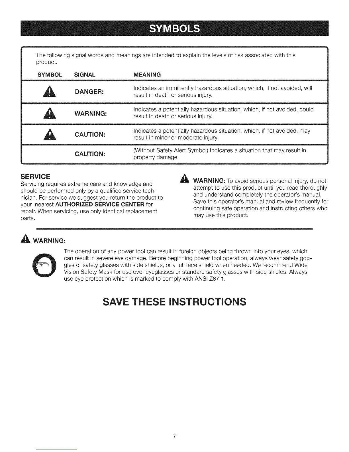
Thefollowingsignalwordsandmeaningsareintendedtoexplainthelevelsofriskassociatedwiththis
product.
SYMBOL SIGNAL MEANING
DANGER:
WARNING: result in death or serious injury.
CAUTION: result in minor or moderate injury.
CAUTION: (Without Safety Alert Symbol) Indicates a situation that may result in
Indicates an imminently hazardous situation, which, if not avoided, will
result in death or serious injury.
Indicates a potentially hazardous situation, which, if not avoided, could
Indicates a potentially hazardous situation, which, if not avoided, may
property damage.
SERVICE
Servicing requires extreme care and knowledge and
should be performed only by a qualified service tech-
nician. For service we suggest you return the product to
your nearest AUTHORIZED SERVICE CENTER for
repair. When servicing, use only identical replacement
parts.
_, WARNING:
The operation of any power tool can result in foreign objects being thrown into your eyes, which
can result in severe eye damage. Before beginning power tool operation, always wear safety gog-
gles or safety glasses with side shields, or a full face shield when needed. We recommend Wide
Vision Safety Mask for use over eyeglasses or standard safety glasses with side shields. Always
use eye protection which is marked to comply with ANSI Z87.1.
A
WARNING: To avoid serious personal injury,do not
attempt to use this product until you read thoroughly
and understand completely the operator's manual.
Save this operator's manual and review frequently for
continuing safe operation and instructing others who
may use this product.
SAVE THESE INSTRUCTIONS
Page 8

PRODUCT SPECiFiCATIONS
Motor ............................................................... 19.2 Volt DC
Switch ............................................................ Single Speed
No Load Speed ................................................ 28,000/min.
SPINDLELOCK
BUTTON
Collet Size ................................................................. 1/4 in.
Charger Input ................................... 120 V, 60 Hz, AC only
Charge Rate ............................................................. 1 Hour
MOTOR
HOUSING
TRIM ROUTER
WOODWORKING
SUBBASE
DEPTHOFCUT
SCALE
DEPTH
ADJUSTMENT
LATCH
LAMINATE
SUBBASE
Fig. 1
Page 9

KNOW YOUR TRIMMER
See Figure 1,
Before attempting to use this product, familiarize yourself
with all operating features and safety rules.
DEPTH ADJUSTMENT LATCH
The latch opens to allow the trimmer to be moved up or
down for easy adjustment of the cutting depth.
DEPTH OF CUT SCALE
Your trimmer has a depth of cut scale on each side of the
tool.
DUAL GRiP
Your trimmer is designed for either right-handed or left-
handed operation when used with the laminate subbase.
LAMINATE SUBBASE
The laminate subbase is included for laminate trimming
operations.
SPINDLE LOCK BUTTON
The spindle lock button allows quick bit changes.
SWITCH
The ON/OFF switch is located on the back of the motor
housing, facing the operator.
TRIM ROUTER WOODWORKING SUBBASE
Easily adapts the tool from atrimmer to a trim router ca-
pable of light-duty routing operations.
UNPACKING ,_
This product has been shipped completely assembled.
[] Carefully remove the tool and any accessories from the
box. Make sure that all items listed in the packing list
are included.
[] Inspect the tool carefully to make sure no breakage or
damage occurred during shipping.
[] Do not discard the packing material until you have
carefully inspected and satisfactorily operated the tool.
[] If any parts are damaged or missing, please call
1-800-932-3188 for assistance.
A
A
PACKING LIST
Trimmer
Laminate Subbase (Installed)
Trim Router Woodworking Subbase
Woodworking Subbase Handles (2)
Wrench
Operator's Manual
A
WARNING: If any parts are missing do not operate
this tool until the missing parts are replaced. Failure
to do so could result in possible serious personal
injury.
WARNING: Do not attempt to modify this tool
or create accessories not recommended for use
with this tool. Any such alteration or modification is
misuse and could result in a hazardous condition
leading to possible serious personal injury.
WARNING: To prevent accidental starting that
could cause serious personal injury, always remove
the battery pack from the tool when assembling
parts.
WARNING: Always use the laminate subbase for
laminate trimming. Always use the woodworking
subbase for trim routing operations. Use of the trim-
mer without a subbase or using the incorrect sub-
base can result in serious personal injury.
Page 10

INSTALLiNG/REMOVING BITS
See Figures 2 - 3.
If installing the bit for the first time, it can be installed once
the collet nut is loose. If changing bits, the bit will easily slip
from the collet after loosening the collet nut.
[] Turn the switch to OFF and remove the battery pack
from the trimmer.
[] Place the trimmer upside down on a workbench.
[] To remove the subbase assembly, open the depth
adjustment latch. Slide the base upward, then left, then
upward again to remove the base.
[] Depress the spindle lock button.
[] Use the wrench provided to turn the collet nut in a
counterclockwise direction. Continue to depress the
spindle lock button while loosening the collet nut.
[] With the tool still upside down on a workbench, insert
the shank of the bit into the collet. The shank of the bit
should be close to but not touching the bottom of the
collet. This allows for expansion when the bit gets hot.
A clearance of 1/16 in. is adequate.
NOTE: The collet is machined to precision tolerances to fit
bits with 1/4 in. diameter shanks.
[]
Hand-tighten the collet nut. Then, depress the spindle
lock button and continue tightening the collet nut with
the wrench provided by turning it in a clockwise direc-
tion.
STOP
GROOVE
SUBBASE
DEPTH
ADJUSTMENT
LATCH
Fig. 2
BiT
_ WARNING: If the collet nut is not tightened secure-
ly, the bit may come out during use, causing serious
personal injury.
[] Replace the subbase assembly by sliding it onto the
tool, along the grooves on the sides of the tool.
NOTE: Replace the base before using the tool. Do not
attempt to operate the tool without the base installed.
[] Close the depth adjustment latch.
[] Replace the battery pack.
,_ WARNING: If you are changing a bit immediately
after use, be careful not to touch the collet nut, bit,
or collet with your hands or fingers. They will get
burned because of the heat buildup from cutting.
Always use the wrench provided.
WRENCHON
COLLETNUT
TOLOOSEN
TOTIGHTEN
SPINDLELOCK
BUTTON
Fig. 3
10
Page 11

A
WARNING: Do not allow familiarity with tools to
make you careless. Remember that a careless
fraction of a second is sufficient to inflict serious
injury.
A
WARNING: Always wear safety goggles or safety
glasses with side shields when operating tools.
Failure to do so could result in objects being thrown
into your eyes, resulting in possible serious injury.
A
WARNING: Do not use any attachments or acces-
sories not recommended by the manufacturer of
this tool. The use of attachments or accessories not
recommended can result in serious personal injury.
APPLICATIONS
You may use this tool for the following purposes:
When used with the laminate subbase this tool may be
used for:
[] Smooth, professional trimming of laminates and wood
veneer
When used with the woodworking subbase with handles, this
tool may be used for the following light-duty applications:
[] Routing grooves and shaping edges in wood
[] Chamfering, rabbeting, dadoing, and dovetailing in
wood
[] Routing edges on plastic laminates
CAUTION: If at any point during the charging
process none of the LEDs are lit, remove the bat-
tery pack from the charger to avoid damaging the
product. DO NOT insert another battery. Return the
charger and battery to your nearest service center
for service or replacement.
LED FUNCTIONS OF CHARGER
LED WILL BE ON TO INDICATE STATUS OF
CHARGER AND BATTERY PACK:
[] Red LED on = Fast charging mode.
[] Green LED on = Fully charged and in maintenance
charge mode.
[] Green LED on = When battery pack is inserted into
charger, indicates hot battery pack or that battery pack
is out of normal temperature range.
[] Yellow and Green LEDs on = Deeply discharged or
defective battery pack.
[] No LED on = Defective charger or battery pack.
CHARGING THE BATTERY PACK
Battery packs for this tool are shipped in a low charge
condition to prevent possible problems. Therefore, you
should charge it until the green LED on the front of the
charger comes on.
NOTE: Batteries will not reach full charge the first time
they are charged. Allow several cycles (operation followed
by recharging) for them to become fully charged.
CHARGING A COOL BATTERY PACK
If battery pack is below normal temperature range, the
green LED on charger will come on. Allow battery pack to
reach normal temperature, then the red LED will come on.
NOTE: If the charger does not charge the battery pack
under normal circumstances, return both the battery pack
and charger to your nearest Sears Repair Center for
electrical check.
[]
Charge the battery pack only with the charger provided.
[]
Make sure the power supply is normal household
voltage, 120 vo(ts, 60 Hz, AC only.
[]
Connect the charger to the power supply.
[]
Place the battery pack in the charger aligning raised rib
on the battery pack with the groove in the charger. See
Figure 5.
[]
Press down on the battery pack to be sure contacts on
the battery pack engage properly with contacts in the
charger.
[]
Normally the red LED on charger will come on. This
indicates the charger is in fast charging mode.
[]
Red LED should remain on for approximately 1 hour
then the green LED will come on. Green LED on
indicates battery pack is fully charged and charger is
in maintenance charge mode.
NOTE: The green LED will remain on until the battery
pack is removed from the charger or charger is
disconnected from the power supply.
[]
If both yellow and green LEDs come on, this indicates
a deeply discharged or defective battery pack. Allow
the battery pack to remain in the charger for 15 to 30
minutes. When the battery pack reaches normal
voltage range, the red LED should come on. If the red
LED does not come on after 30 minutes, this may
indicate a defective battery pack and should be
replaced.
[]
After normal usage, a minimum of 1 hour of charging
time is required to fully recharge battery pack.
[]
The battery pack will become slightly warm to the
touch while charging. This is normal and does not
indicate a problem.
[]
Do not place the charger and battery pack in an area
of extreme heat or cold. They will work best at normal
room temperature.
11
Page 12

NOTE:Thechargerandbatterypackshouldbeplaced
inalocationwherethetemperatureismorethan50°F
butlessthan100°F.
[] Whenbatteriesbecomefullycharged,unplugthe
chargerfrompowersupplyandremovethebattery
pack.
CHARGING A HOT BATTERY PACK
When using the tool continuously, the batteries in the
battery pack will become hot. You should let a hot bat-
tery pack cool down for approximately 30 minutes before
attempting to recharge. When the battery pack becomes
discharged and is hot, this will cause the green LED to
come on instead of the red LED. After 30 minutes, reinsert
the battery pack in the charger. If the green LED continues
to remain on, return battery pack to your nearest Sears
Repair Center for checking or replacing.
NOTE: This situation only occurs when continuous use of
the tool causes the batteries to become hot. It does not
occur under normal circumstances. Refer to "CHARG-
iNG A COOL BATTERY PACK" for normal recharging
of batteries. If the charger does not charge your battery
pack under normal circumstances, return both the battery
pack and charger to your nearest Sears Repair Center for
electrical check.
YELLOWLED
REDLED
GREEN
LED
iNSTALLING THE BATTERY PACK
See Figure 6.
[] Place the battery pack in the tool. Align the raised rib
on the battery pack with the groove inside the trimmer,
then slide the battery pack into the tool.
A
WARNING: Always be sure the switch is inthe OFF
position before installing the battery pack. Failure
to do so could cause accidental starting, leading to
serious personal injury.
[]
Make sure the latches on each side of the battery pack
snap into place and the battery pack is secured in the
tool before beginning operation.
CAUTION: When placing battery pack in the tool,
be sure raised rib on battery pack aligns with the
bottom of the tool and latches into place properly.
Improper installation of the battery pack can cause
damage to internal components.
REMOVING THE BATTERY PACK
See Figure 6.
[] With the switch in the OFF position, locate the latches
on the side of the battery pack and depress them to
release the battery pack from the tool.
[] Remove the battery pack.
BATTERYPACKSHOWNIN CHARGER
Fig. 5
BATTERY
PACK
LATCH
Fig. 6
12
Page 13

A
WARNING: Battery tools are always in operating
condition. Therefore, switch should always be locked
when not in use or carrying at your side.
OPERATING THE TRIMMER
Before starting the trimmer, with the battery pack discon-
nected, make sure the bit is securely tightened in the
collet and that the depth of cut is properly set. Never start
the tool while the bit is in contact with the workpiece.
When cutting, locate the base of the tool over the work
surface and firmly hold the body of the trimmer with your
hand. Make sure the tool is running at full speed before
contacting the workpiece.
After completing a cut, pull the bit slightly away from the
cut surface. Turn the trimmer off and wait for the rotating
bit to completely stop before completely removing the tool
from the work surface.
GRIPPING THE TRIMMER
See Figure 8.
When used with the laminate subbase, the trimmer has a
dual grip design that allows the operator to hold the tool
with either the right or left hand.
For right-handed operation, the depth adjustment latch
must be on the left side of the tool. For left-handed opera-
tion, the depth adjustment latch must be on the right side
of the tool.
Always hold the trimmer so that the switch is facing you
and your thumb is positioned above the depth adjustment
latch.
To change grip positions, remove the laminate subbase
(See Installing/Removing Trimming Bits). Re-position
the base for right- or left-handed operation.
NOTE: Replace the base before using the trimmer. Do not
attempt to operate the tool without the base installed.
TURNING THE TRIMMER ON/OFF
See Figure 7.
To turn the trimmer ON, slide the switch on front of the
tool to the ON position. Return the switch to the OFF
position when finished.
ON
_ WARNING: Avoid hand positions that may expose
fingers to bit through open areas of the base. Fingers
entering the opening in the base can be seriously cut
or burned.
CAUTION: To avoid damaging the motor from over-
heating, do not let your hand cover the air vents.
RIGHT-HANDEDUSE
(WITHLAMINATE
SUBBASE)
Fig. 7
LEFT-HANDEDUSE
(WITHLAMINATE
SUBBASE)
Fig. 8
13
Page 14

DEPTH OF CUT
See Figure 9.
Depth of cut affects the rate of feed and the quality of a
cut. Using the proper depth of cut can lessen the possibil-
ity of damage to the motor and bit.
A deeper cut requires a slower feed than a shallow one.
Making a cut that is too deep will slow the feed so that
the bit is scraping, rather than cutting, and is not recom-
mended.
A too-deep cut can cause smaller bits to be broken off.
Bits that are 1/16 in. diameter are easily broken off when
subjected to too much side thrust. A larger bit is not as
likely to break, but attempting a cut that is too deep may
result in a rough cut, and may make it difficult to guide
and control the bit as desired.
It is necessary that you do not exceed 1/8 in. depth of cut
in a single pass, regardless of the bit size or the softness
or condition of the workpiece. This will result in a higher
quality cut.
To make deeper cuts, it is necessary to make as many
successive passes as required, lowering the bit 1/8 in. for
each new pass. To save time, perform all the cutting nec-
essary at one depth setting, then lower the bit for the next
pass. This will assure uniform depth when the final pass is
completed.
_I_L WARNING: If the desired depth of cut is greater
than can be safely cut in one pass, make cuts in
two or more passes. Do not remove more than 1/8
in. with a single pass. Excessive depth of cut can
result in loss of control and the possibility of serious
personal injury.
SETTING DEPTH OF CUT
See Figure 10.
[] With the switch in the OFF position, remove the battery
pack from the tool.
[] Open the depth adjustment latch as indicated by the
arrow.
[] Slide the motor housing section of the tool upward until
the tip of the bit reaches the work surface. The depth
of cut is zero at this point.
[] Adjust the position of the tool to obtain the desired
depth of cut by moving the motor housing section
up or down, as shown by the up/down arrow. The
distance the bit moves can be read on the depth of
cut scale. Each mark on the scale indicates a 1/16 in.
change in depth setting. Indicator points are located on
the base.
[] Completely close the depth adjustment latch.
A
WARNING: Avoid open area of the base. Serious
personal injury will result from contact with a rotating
bit.
NOTE: To make deeper cuts, it is necessary to make as
many successive passes as required, lowering the bit
1/8 in. for each new pass. To save time, perform all the
cutting necessary at one depth setting, then lower the bit
for the next pass. This will ensure uniform depth when the
final pass is completed.
DEPTH
OFCUT
1ST. PASS
1ST.
2N0. PASS 2N0. PASS
PASS
WIDTH
0FCUT
Fig. 9
14
DEPTHOF
CUTSCALE
i
__ DEPTH
LATCH
ADJUSTMENT
TOOLSHOWNWITH LAMINATESUBBASE
Fig. 10
Page 15

DiRECTiON OF FEED AND THRUST
See Figures 11 - 12.
The motor and bit revolve in a clockwise direction. This
gives the tool a slight tendency to twist in a counterclock-
wise direction, especially when the motor starts.
Feed the trimmer into the workpiece from left to right.
When fed from left to right, the rotation of the bit pulls the
tool against the workpiece. If fed in the opposite direc-
tion, the rotation forces of the spinning bit will tend to
throw the tool away from the workpiece, causing kick-
back. This could result in loss of control of the tool.
Because of the high speed of bit rotation during a proper
feeding operation, there is very little kickback to contend
with under normal conditions. However, if the bit strikes
a knot, hard grain, foreign object, etc. that affects the
normal progress of the cutting action, there will be a slight
kickback. Kickback is always in the direction opposite
the direction of bit rotation. This will affect the trueness of
your cut.
To guard against kickback, plan your setup and direction
of feed so that you will always be thrusting the tool in the
same direction that the leading edge of the bit is moving.
The thrust should be in a direction that keeps the sharp
edges of the bit continuously biting straight into new (un-
cut) wood.
NOilO3UIQ
033d
4
LU
z
0¢
j ...............JJ
__ BIT
ROTATION
FEED
DIRECTION
Fig. 11
GUIDEOUTSIDE
THRUST
FEED
ROTATION
GUIDE
GUIDEINSIDE
ROTATION _,
GUIDE
_" FEED
THRUST
Fig. 12
15
Page 16

PROPER RATE OF FEED
Trimming and edge shaping depend upon careful setup
and selecting the proper feed rate.
The proper feed rate is dependent upon:
[] hardness and moisture content of the workpiece;
[] depth of cut;
NOTE: It is necessary that you do not exceed 1/8 _n.
depth of cut for proper rate of feed.
[] cutting diameter of the bit.
NOTE: Maximum bit size for roundover and edging
operations is 3/8 in. max. Maximum straight bit size for
rabbeting and dado operations is 1/4 in.
For edge shaping in soft woods such as pine, a faster rate
of feed can be used. When edge shaping in hardwoods
such as oak, a slower rate of feed will be required. In all
wood types, a slower rate of feed is required when cutting
shallow grooves.
Several factors will help you select the proper rate of feed.
[] Choose a rate that does not slow down the motor.
[] Choose the rate of feed at which the bit advances
firmly and surely to produce a continuous spiral of
uniform chips or a smooth trim edge on laminate.
[] Listen to the sound of the motor. A high-pitched sound
means you are feeding too slowly. A strained, lower
pitched sound signals force feeding.
[] Check the progress of each cut. Too-slow feeding can
cause the trimmer to take off in a wrong direction from
the intended line of cut. Force-feeding increases the
strain of holding the tool and can result in damage to
the tool.
[] Notice the chips being produced as you cut. If the trim-
mer is fed too slowly, it will scorch or burn the wood. If
the trimmer is fed too fast, it will take large chips out of
the wood and leave gouge marks.
Always test a cut on scrap piece of the workpiece wood
or laminate before you begin. Always grasp and hold the
tool firmly during use.
When using the largest recommended straight bit (1/4 in.)
in any type of wood, maintain a maximum cutting depth of
1/8 in. and a very slow feed rate to achieve the best qual-
ity cut. A cross-grain cut requires a slower pace than an
identical cut with the grain in the same workpiece.
There is no fixed rule. Proper feed rate is learned through
practice and use.
16
Page 17

FEEDING TOO FAST/FORCE FEEDING
See Figure 13.
The trimmer is a high-speed tool (28,000/min.), and will
make clean, smooth cuts if allowed to run freely without
the overload of a forced or too-fast feed. Three things
that cause force feeding are bit size, depth of cut, and
workpiece characteristics. The larger the bit or the deeper
the cut, the more slowly the trimmer should be moved
forward. If the wood is very hard, knotty, gummy or damp,
the operation must be slowed still more.
Clean, smooth trimming and edge shaping can be done
only when the bit is revolving at a relatively high speed
and is taking very small bites to produce tiny, cleanly-sev-
ered chips. If the trimmer is forced to move forward too
fast, the speed of the bit becomes slower than normal in
relation to its forward movement. As a result, the bit must
take bigger bites as it revolves. Bigger bites mean bigger
chips and a rougher finish. Bigger chips also require more
power, which could result in overheating of the motor and
lower battery life.
Under extreme force-feeding conditions, the relative
speed of the bit can become so slow - and the bites it has
to take so large - that chips will be partially knocked off
rather than fully cut off. This will result in splintering and
gouging of the workpiece and will likely damage the tool.
FEEDING TOO SLOW
See Figure 14.
When the tool is advanced into the work too slowly it
scrapes away sawdust-like particles instead of cleanly
cutting into the workpiece. Scraping produces heat, which
can glaze, burn, or mar the cut, and can overheat the bit.
Dull bits can also contribute to scraping and burning.
It is more difficult to control atrimmer when the bit is
scraping instead of cutting. With practically no load on
the motor, the bit will be revolving near top RPM. When
feeding too slowly, the bit will have a greater than normal
tendency to bounce off the sides of the cut, especially
if the wood has a pronounced grain with hard and soft
areas. The cut that results may have rippled sides instead
of straight.
TOOSLOW
Fig. 14
TOOFAST
Fig. 13
17
Page 18

WOODWORKING SUBBASE
The woodworking subbase with handles is convenient
when routing 4 in., 5 in., or 6 in. circular grooves. It can
also be used when routing grooves parallel to the edge of
the workpiece or with ball-bearing piloted bits.
The handles allow you to grasp and hold the tool with two
hands, similar to grasping and holding a router.
This tool is designed for roundover bits up to 3/8 in. and
other edging operations. It is also useful for rabbeting or
dado operations with straight bits up to a maximum diam-
eter of 1/4 in.
A
WARNING: Do not use straight bits larger than
1/4 in. or edging bits which cut a pattern larger than
3/8 in. with this tool. Use of larger bits can result in
loss of control and serious personal injury.
A
WARNING: Always use the laminate subbase for
laminate trimming. Always use the woodworking
subbase for trim routing applications. Use of the tool
without a subbase or using the incorrect subbase
can result in serious personal injury.
TRIMMER
HANDLE(S)
i
i
J
A
WARNING: Never install a bit larger than 1-1/4 in.
diameter or larger in diameter than the opening in the
subbase. The use of larger bits can result in loss of
control and possible serious personal injury.
ATTACHING THE WOODWORKING SUBBASE
AND HANDLES
See Figure 15.
[] Turn the switch to OFF and remove the battery pack
from the tool.
[] Turn the tool upside down to remove the four subbase
screws and laminate subbase.
[] Attach the woodworking subbase using the same four
screws.
[] Tighten the screws securely. Do not overtighten.
[] Turn the tool upright and thread the handles provided
into the threaded holes in the woodworking subbase.
[] Tighten the handles securely. Check often to ensure
the handles remain securely tightened.
WOODWORKING
SUBBASE
SUBBASE
SCREW(S)
Fig. 15
ROUTING GROOVES IN A CIRCLE
See Figure 16.
[] There are three holes marked R2", R2-1/2", and R3" on
the woodworking subbase. Each number represents a
radius and may be used when cutting circular grooves
that are 4 in., 5 in. or 6 in. in diameter.
[] Select the radius for the desired circle, place a finish-
ing nail through the hole and securely tack it into the
workpiece. This will create a pivot axis for that size
radius.
[] Rout a circular groove in a clockwise direction only.
18
Page 19

ROUTCIRCULARGROOVECLOCKWISE
FINiSHiNG
NAIL
\ )
WORKPIECE Fig. 16
A
WARNING: If the desired depth of cut is greater
than can be safely cut in one pass, make cuts in two
or more passes. Do not remove more than
1/8 in. with a single pass. Excessive depth of cut can
result in loss of control and the possibility of serious
personal injury.
ROUTGROOVEFROMRIGHTTO LEFT
ROUTING GROOVES PARALLEL TO AN EDGE
See Figures 17- 18.
You can use the scale provided on the woodworking sub-
base to cut a straight parallel line up to 1 in. from the edge
of the workpiece.
[] The intersection of the horizontal and vertical lines at
the center of the woodworking subbase indicates the
center of the cutter. This is also the center of groove
being cut.
[] For grooves more than 1 in. from the edge of
workpiece, align the center of desired groove on the
workpiece with the centerline on the woodworking
subbase. Then measure from the centerline on the
woodworking subbase to the guiding portion of the
straight guide. Tighten the knob on the straight guide
securely.
[] Using "C" clamps and a board to act as the straight
edge, place the cutter at the desired position on the
workpiece and make the cut from right to left.
NOTE: The board being used as a straight edge must
be 1/4 in. thick to prevent contact with the trim router
base. It must also be at least as long as the workpiece
in order to be a guide.
[] The thrust is from the trim router against the straight
edge.
[] Do not make a cut that is too heavy in one pass. If
a deep cut is required, make successive passes at
increasing depths with each new pass until you reach
the desired groove depth.
Fig. 17
TRiM ROUTERUSEDWITHA BALL-BEARINGGUIDEDBIT
Fig. 18
19
Page 20

A
WARNING: When servicing, use only identical
Craftsman replacement parts. Use of any other part
may create a hazard or cause product damage.
Only the parts shown on the parts list are intended to be
repaired or replaced by the customer. All other parts
should be replaced at a Sears Service Center.
A
WARNING: Always wear safety goggles or safety
glasses with side shields when using compressed air
to clean tools. If the operation is dusty, also wear a
dust mask.
A
WARNING: To avoid serious personal injury, always
remove the battery pack from the tool when cleaning
or performing any maintenance.
GENERAL MAINTENANCE
Avoid using solvents when cleaning plastic parts. Most
plastics are susceptible to damage from various types of
commercial solvents and may be damaged by their use.
Use clean cloths to remove dirt, dust, oil, grease, etc.
A
WARNING: Do not at any time let brake fluids,
gasoline, petroleum-based products, penetrating
oils, etc. come in contact with plastic parts. Chemi-
cals can damage, weaken or destroy plastic which
may result in serious personal injury.
ADJUSTING TENSION ON THE DEPTH
ADJUSTMENT LATCH
With use, the depth adjustment latch may loosen. Periodi-
cally check the latch and adjust it when necessary.
[] Turn the switch to OFF and remove the battery pack
from the tool.
[] Open the depth adjustment latch.
[] Using the adjusting wrench provided, tighten the hex
nut by turning it clockwise. Do not overtighten.
[] Close the latch and assure the latch is securely tight-
ened by checking the subbase assembly. It should not
move.
BATTERIES
The battery pack for this tool is equipped with nickel-cad-
mium rechargeable batteries. Length of service from each
charging will depend on the type of work you are doing.
The batteries in this tool have been designed to provide
maximum trouble-free life. However, like all batteries, they
will eventually wear out. Do not disassemble battery pack
and attempt to replace the batteries. Handling of these
batteries, especially when wearing rings and jewelry, could
result in a serious burn.
To obtain the longest possible battery life, we suggest the
following:
[] Remove the battery pack from the charger once it is
fully charged and ready for use.
For battery pack storage longer than 30 days:
[] Store the battery pack where the temperature is below
80°F.
[] Store battery packs in a "discharged" condition.
BATTERY PACK REMOVAL AND
PREPARATION FOR RECYCLING
To preserve natural resources, please
recycle or dispose of batteries
properly.
This product contains nickel-cadmium
batteries. Local, state or federal
laws may prohibit disposal of nickel-
cadmium batteries in ordinary trash.
Consult your local waste authority for information
regarding available recycling and/or disposal options.
_IL WARNING: Upon removal, cover the battery pack's
terminals with heavy-duty adhesive tape. Do not
attempt to destroy or disassemble battery pack or
remove any of its components. Nickel-cadmium
batteries must be recycled or disposed of properly.
Also, never touch both terminals with metal objects
and/or body parts as short circuit may result. Keep
away from children. Failure to comply with these
warnings could result in fire and/or serious injury.
20
Page 21

CRAFTSMAN 19.2V TRIMMER MODEL NUMBER 315.115830
The model number will be found on a plate attached to the motor housing. Always mention the modelnumber in all correspondence regarding your TRIMMER or when ordering repair parts,
SEE BACK PAGE FOR PARTS ORDERING INSTRUCTIONS
15
14
13
10
9
I
I
I
t.
2
}
3
PARTS LIST
Key Part
No. Number Description Qty.
1 690604002 Wrench ............................................................................................................ 1
2 513432001 Woodworking Subbase Handle ....................................................................... 2
3 550818002 Woodworking Subbase ................................................................................... 1
4 690043002 Collet Nut ........................................................................................................ 1
5 690045002 Col let ............................................................................................................... 1
6 660279004 * Screw (M4 x 12 mm Flat Hd.) .......................................................................... 4
7 512047001 Laminate Subbase .......................................................................................... 1
8 6797401 * Lock Nut (M5) .................................................................................................. 1
9 670060001 * Washer ............................................................................................................ 1
10 342046002 Motor Housing Base ....................................................................................... 1
11 671352001 * Washer ............................................................................................................ 1
12 200397001 Latch Assembly ............................................................................................... 1
13 200234006 Base Assembly ................................................................................................ 1
14 940114130 Logo Plate ....................................................................................................... 1
15 941018001 Data Plate ........................................................................................................ 1
983000643 Operator's Manual
• Standard Hardware Item - May Be Purchased Locally
21
Page 22

Your Home
For repair-in your home-of all major brand appliances,
lawn and garden equipment, or heating and cooling systems,
no matter who made it, no matter who sold it!
For the replacement parts, accessories and
owner's manuals that you need to do-it-yourself.
For Sears professional installation of home appliances
and items like garage door openers and water heaters.
1-800-4-MY-HOME ® (1-800-469-4663)
Call anytime, day or night (U.S.A. and Canada)
www.sears.com www.sears.ca
Our Home
For repair of carry-in items like vacuums, lawn equipment,
and electronics, call or go on-line for the location of your nearest
Sears Parts & Repair Center.
1-800-488-1222
Call anytime, day or night (U.S.A. only)
www.sears.com
To purchase a protection agreement (U.S.A.)
or maintenance agreement (Canada) on a product serviced by Sears:
1-800-827-6655 (U.S.A.) 1-800-361-6665 (Canada)
Para pedir servicio de reparaci6n
a domicilio, y para ordenar piezas:
1-888-SU-HOGAR SM
(1-888-784-6427)
® Registered Trademark / TMTrademark / su Service Mark of Sears, Roebuck and Co.
® Marca Registrada / TM Marca de Fabrica / Marca de Servicio de Sears, Roebuck and Co.
MCMarque de commerce / Marque depos6e de Sears, Roebuck and Co. ® Sears, Roebuck and Co.
MD
SM
Au Canada pour service en fran£ais:
1-800-LE-FOYER Mc
(1-800-533-6937)
www.sears.ca
 Loading...