

Page 1
Operator's Manual
3/8 in. CORDLESS DRILL-DRIVER
Variable Speed / Reversible
Model No.
315.115200 13.2 Volt
315.115210 15.6 Volt
Save this manual for
future reference
,_ WARNING: To reduce the risk of injury, the
user must read and understand the operator's
manual before using this product.
Customer Help Line: 1-800-932-3188
Sears, Roebuck and Co., 3333 Beverly Rd., Hoffman Estates, IL 60179 USA
Visit the Craftsman web page: www.sears.com/craftsman
983000-170
12-03
0Q°s
Page 2
• Warranty .......................................................................................................................................................................... 2
• lntroducton ..................................................................................................................................................................... 2
• Genera(Safety Ru(es ................................................................................................................................................. 3-4
• Specific Safety Ru(es ................................................................................................................................................... 4
• Safetylnstructions For Charger ...................................................................................................................................... 5
• Symbols ...................................................................................................................................................................... 6-7
• Features ...................................................................................................................................................................... 8-9
• Unpacking ....................................................................................................................................................................... 9
• Operation ................................................................................................................................................................. 10-15
• Maintenance ................................................................................................................................................................. 16
• Accessories .................................................................................................................................................................. 16
• Exploded View and Repair Parts List....................................................................................................................... 18-19
• Parts Ordering/Service ............................................................................................................................................... 20
FULL ONE YEAR WARRANTY ON CRAFTSMAN 3./8 in, CORDLESS DRILL-DRIVER
(fth(s 3/8 in. CRI_FTSMI_N°too( fails to give comp(ete satisfaction within one year from the date of purchase, RETURN IT
TO THE NEAREST SEARS STORE OR SEARS SERVICE CENTER IN THE UNITED STATES, and Sears w((I replace it,
free of charge.
(fthis 3/8 in. I:RI_I=TSMAN°tool is used for commercial or rental purposes, this warranty applies for only 90 days from
the date of purchase.
This warranty gives you specific legal rights, and you may also have other rights which vary from state to state.
Sears, Roebuck and Co,, Dept, 817WA, Hoffman Estates, IL 60179
This tool has many features for making your drilling opera-
tions more pleasant and enjoyable. Safety, performance
and dependability have been given top priority in the
design of this dri(Fdriver making it easy to maintain and
operate.
WARNING: Do not attempt to use this product until
you read thoroughly and understand compiete(y the
operator's manual. Pay close attention to the safety
rules including Dangers, Warnings and Cautions. If
you use this product properly and only as intended,
you will en(oy years of safe, reliable service.
2
Page 3
WARNING: READ AND UNDERSTAND ALL IN-
STRUCTIONS. Failure to fo{Iow a(I {nstruct(ons {{sted
be(ow, may result {nelectric shock, fire and/or seri-
ous personal injury.
SAVE THESE INSTRUCTIONS
WORK AREA
• Keep your work area clean and well lit. Cluttered
benches and dark areas invite accidents.
• Do not operate power tools in explosive atmo-
spheres, such as in the presence of flammable
liquids, gases, or dust. Power too(s create sparks
which may ignite the dust or fumes.
• Keep bystanders, children, and visitors away while
operating a power tool. Distractions can cause you
to lose control.
ELECTRICAL SAFETY
• A battery operated tool with integral batteries or a
separate battery pack must be recharged only with
the specified charger for the battery. A charger that
may be su(table for one type of battery may create a
risk of fire when used with another battery. Use bat-
tery only w(th charger listed.
MODEL BATTERY PACK CHARGER
315.115200 ITEM NO. 9 11525 tTEM NO. 9 11526
{130139018) (140287001)
315.115210 ITEM NO. 9 11465 tTEM NO. 9 11466
{130139015) (140250013)
• Use battery operated tool only with specifically
designated battery pack. Use of any other batteries
may create a risk of fire. Use on(y w(th battery pack
listed.
• Do not abuse the cord. Never use the cord to carry
the charger, Keep cord away from heat, oil, sharp
edges, or moving parts. Replace damaged cords
immediately. Damaged cords may create a fire.
PERSONAL SAFETY
• Stay alert, watch what you are doing and use com-
mon sense when operating a power tool, Do not
use tool while tired or under the influence of drugs,
alcohol, or medication. A moment of inattention
wh((e operating power tools may result in serious per-
sonal injury.
• Dress properly. Do not wear loose clothing or
jewelry. Contain long hair. Keep your hair, clothing,
and gloves away from moving parts. Loose c(othes,
jewelry, or long hair can be caught in mov(ng parts.
• Avoid accidental starting. Be sure switch is in
the locked or off position before inserting battery
pack. Carrying tools w(th your finger on the switch or
inserting the battery pack (nto a tool with the switch
on, inv(tes acc(dents.
• Remove adjusting keys or wrenches before turning
the tool on. A wrench or a key that }s left attached to
a rotating part of the too( may result in persona( injury.
Do not overreach. Keep proper footing and bal-
ance at all times. Proper footing and balance enables
better centre} of the tool (n unexpected situations. Do
not use on a ladder or unstable support.
• Use safety equipment. Always wear eye protection.
Dust mask, non-sk)d safety shoes, hard hat, or hear(ng
protect)on must be used for appropriate conditions.
• Do not wear loose clothing or jewelry. Contain long
hair. Loose clothes, jewelry, or long hair can be drawn
(nto a(rvents.
• Do not use on a ladder or unstable support. Stab(e
footing on a so((d surface enables better control of the
tool in unexpected situat(ons.
TOOLUSEAND CARE
• Use clamps or other practical way to secure and sup-
port the workpieoe to a stable platform. Hold(ng the
work by hand or against your body is unstable and may
lead to loss of control.
• Do not force tool. Use the correct tool for your appli-
cation. The correct too( wil( do the job better and safer at
the rate for which it is designed.
• Do not use tool if switch does not turn it on or off. A
tool that cannot be control(ed with the switch is dan-
gerous and must be repaired.Tool Use and Care
• Disconnect battery pack from tool or place the switch
in the locked or off position before making any ad-
justments, changing accessories, or storing the tool.
Such preventive safety measures reduce risk of starting
the tool accidenta(ly.
• Store idle tools out of reach of children and other
untrained persons. Tools are dangerous in the hands of
untrained users.
• When battery pack is not in use, keep it away from
other metal objects like: paper clips, coins, keys,
nails, screws, or other small metal objects that can
make a connection from one terminal to another.
Shorting the battery terminals together may cause
sparks, burns, or a fire.
• Maintain tools with care. Keep cutting tools sharp
and clean. Properly mainta(ned tools, with sharp cutting
edges are less ((ke(y to bind and are easier to control.
• Check for misalignment or binding of moving parts,
breakage of parts, and any other condition that may
affect the tool's operation. If damaged, have the tool
serviced before using. Many accidents are caused by
poorly maintained too}s.
• Use only accessories that are recommended by the
manufacturer for your model. Accessories that may
be su(table for one tee(, may create a risk of injury when
used on another tool
Keep the tool and its handle dry, clean and free from
oil and grease. Always use a clean cloth when clean(ng.
Never use brake fluids, gaso((ne, petro(eum-based prod-
ucts, or any strong solvents to clean your tool
3
Page 4
SERVICE
• Tool service must be performed only by qualified
repair personnel, Service or maintenance performed
by unqualified personnel may result in a risk of injury.
• When servicing a tool, use only identical replace=
ment parts. Follow instructions in the Maintenance
section of this manual. Use of unauthorized parts or
failure to follow Maintenance Instructions may create a
risk of shock or injury.
• Hold tool by insulated gripping surfaces when
performing an operation where the cutting tool may
contact hidden wiring. Contact with a "live" wire will
also make exposed metal parts of the tool "live" and
shock the operator.
ADDITIONAL RULES FOR SAFE OPERATION
• Know your power tool. Read operator's manual
carefully. Learn its applications and limitations, as
well as the specific potential hazards related to this
tool. Following this rule will reduce the risk of electric
shock, fire, or serious injury.
• Always wear safety glasses with side shields. Ev-
eryday glasses have only impact resistant lenses. They
are NOT safety glasses. Following this rule will reduce
the risk of eye injury.
RULES FOR BATTERY TOOLS
• Battery tools do not have to be plugged into an
electrical outlet; therefore, they are always in
operating condition. Be aware of possible hazards
when not using your battery tool or when changing
accessories. Following this rule will reduce the risk of
electric shock, fire, or serious personal injury.
• Do not place battery tools or their batteries near
fire or heat. This will reduce the risk of explosion and
possibly injury.
• Batteries vent hydrogen gas and can explode in
the presence of a source of ignition, such as a pilot
light. To reduce the risk of serious personal injury,
never use any cordless product in the presence of
open flame. An exploded battery can propel debris and
chemicals. If exposed, flush with water immediately.
• Do not charge battery tool in a damp or wet loca-
tion. Following this rule will reduce the risk of electric
shock.
• For best results, your battery tool should be
charged in a location where the temperature is
more than 50_F but less than 100°F. Do not store
outside or in vehicles.
• Under extreme usage or temperature condi-
tions, battery leakage may occur. If liquid comes
in contact with your skin, wash immediately with
soap and water, then neutralize with lemon juice
or vinegar. If liquid gets into your eyes, flush them
with clean water for at least 10 minutes, then seek
immediate medical attention. Following this rule will
reduce the risk of serious personal injury.
4
Page 5
WARNING: Never use a battery that has been
dropped or received a sharp blow. A damaged battery
is subject to explosion. Properly dispose of a dropped
battery immediately. Failure to heed this warning can
result in serious personal injury.
• Before using battery charger, read all instructions
and cautionary markings in this manual, on battery
charger, and product using battery charger. FoF
lowing this rule will reduce the risk of electric shock,
fire, or serious personal injury.
• To reduce risk of injury, charge only nickel-cad-
mium type rechargeable batteries. Other types of
batteries may burst causing personal injury and
damage. Following this rule w((I reduce the risk of
electric shock, fire, or serious personal injury.
• Do not expose charger to wet or damp condi-
tions. Following this rule will reduce the risk of electric
shock, fire, or serious personal injury.
• Use of an attachment not recommended or sold by
the battery charger manufacturer may result in a
risk of fire, electric shock, or injury to persons. FoF
lowing this rule will reduce the risk of electric shock,
fire, or serious personal injury.
• To reduce risk of damage to charger body and
cord, pull by charger plug rather than cord when
disconnecting charger. Following this rule wi(( re_
duce the risk of electric shock, fire, or serious per-
sonal injury.
• Make sure cord is located so that it will not be
stepped on, tripped over, or otherwise subjected
to damage or stress. Following this rule will reduce
the risk of serious personal injury.
• An extension cord should not be used unless
absolutely necessary. Use of improper extension
cord could result in a risk of fire and electric shock. If
extension cord must be used, make sure:
m That pins on plug of extension cord are the
same number, size and shape as those of
plug on charger.
• That extension cord is properly wired and in
good electrical condition; and
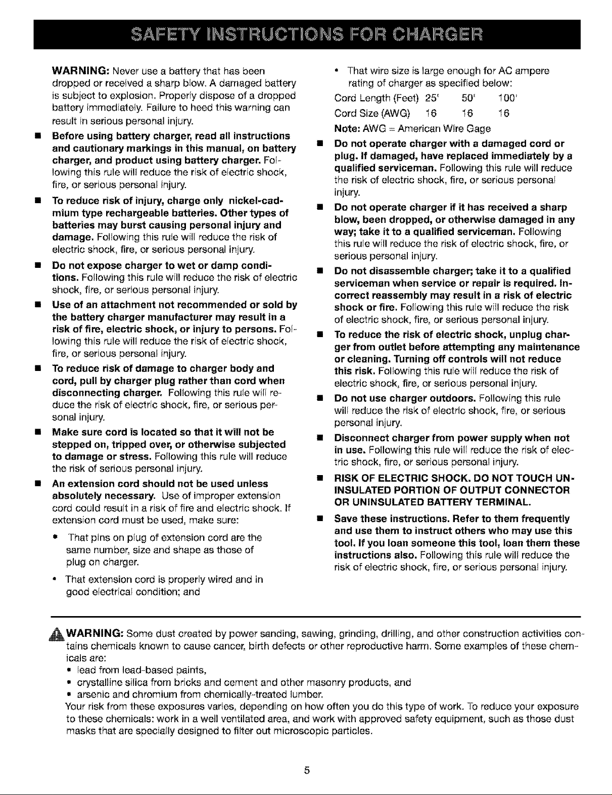
• That wire size is large enough for AC ampere
rating of charger as specified below:
Cord Length (Feet) 25' 50' 100'
Cord Size (AWG) 16 16 16
Note: AWG = American Wire Gage
• Do not operate charger with a damaged cord or
plug. If damaged, have replaced immediately by a
qualified serviceman, Following this rule will reduce
the risk of electric shock, fire, or serious personal
injury.
• Do not operate charger if it has received a sharp
blow, been dropped, or otherwise damaged in any
way; take it to a qualified serviceman. Following
this rule will reduce the risk of electric shock, fire, or
serious personal injury.
• Do not disassemble charger; take it to a qualified
serviceman when service or repair is required. In-
correct reassembly may result in a risk of electric
shock or fire. Foi(owing this rule will reduce the risk
of electric shock, fire, or serious personal injury.
• To reduce the risk of electric shock, unplug char-
ger from outlet before attempting any maintenance
or cleaning. Turning off controls will not reduce
this risk. Following this rule will reduce the risk of
electric shock, fire, or serious personal injury.
• Do not use charger outdoors. Following this rule
will reduce the risk of electric shock, fire, or serious
personal injury.
• Disconnect charger from power supply when not
in use. Follow(ng this rule wi(( reduce the r(sk of elec-
tric shock, fire, or serious personal injury.
• RISK OF ELECTRIC SHOCK. DO NOT TOUCH UN-
INSULATED PORTION OF OUTPUT CONNECTOR
OR UNINSULATED BATTERY TERMINAL.
Save these instructions, Refer to them frequently
and use them to instruct others who may use this
tool. If you loan someone this tool, loan them these
instructions also. Following th(s rule will reduce the
risk of electric shock, fire, or serious personal injury.
_I_WARNING: Some dust created by power sanding, sawing, grinding, drilling, and other construction activities con-
tains chemicals known to cause cancer, birth defects or other reproductive harm. Some examples of these chem-
icals are:
•(ead from lead-based paints,
• crystalline silica from bricks and cement and other masonry products, and
• arsenic and chromium from chemicalIy4reated lumber.
Your risk from these exposures varies, depending on how often you do this type of work. To reduce your exposure
to these chemicals: work in a well ventilated area, and work with approved safety equipment, such as those dust
masks that are speciatly designed to filter out microscopic particles.
5
Page 6
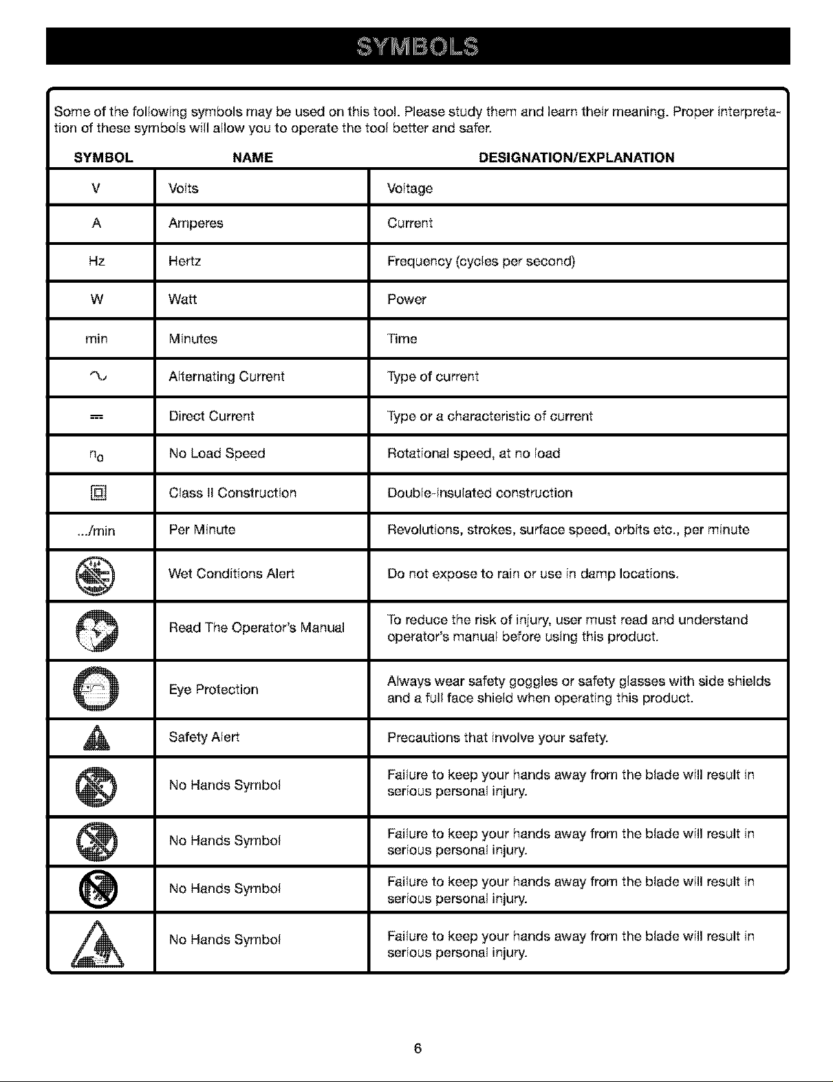
Some of the following symbols may be used on this tool. Please study them and learn their meaning. Proper interpreta-
tion of these symbols will allow you to operate the tool better and safer.
SYMBOL NAME DESIGNATION/EXPLANATION
V Volts Voltage
A Amperes Current
Hz Hertz Frequency (cycles per second)
W Watt Power
rain Minutes Time
"%, Alternating Current Type of current
---= Direct Current Type or a characteristic of current
no No Load Speed Rotational speed, at no load
[] Class II Construction Doubleqnsulated construction
.../rain Per Minute Revolutions, strokes, surface speed, orbits etc., per minute
Wet Conditions Alert Do not expose to rain or use in damp locations.
Read The Operator's Manual To reduce the risk of injury, user must read and understand
Eye Protection Always wear safety goggles or safety glasses with side shields
Safety
_ Failure to keep your hands away from the blade will result in
Alert Precautions that involve
No Hands Symbol serious personal injury.
No Hands Symbol Failure to keep your hands away from the blade will result in
No Hands Symbol Failure to keep your hands away from the blade will result in
operator's manual before using this product.
and a full face shield when operating this product.
safety.
your
serious personal injury.
serious personal injury.
No Hands Symbol Failure to keep your hands away from the blade will result in
serious personal injury.
6
Page 7

Thefollowingsignalwordsandmeaningsareintendedto explainthe levelsof risk associatedwiththis
product,
SYMBOL SIGNAL MEANING
DANGER:
WARNING:
CAUTION:
CAUTION:
Indicates an imminently hazardous situation, which, if not avoided, will
result in death or serious injury.
Indicates a potentially hazardous situation, which, if not avoided, could
result in Death or serious injury.
Indicates a potentially hazardous situation, which, if not avoided, may
result in minor or moderate iniury.
0Nithout Safety Alert Symbol) Indicates a situation that may result in
property damage.
SERVICE
Servicing requires extreme care and knowledge and should
be performed only by a qualified service technician. For
service we suggest you return the product to your nearest
AUTHORIZED SERVICE CENTER for repair. When servic-
ing, use only identical replacement parts.
Observe all normal safety precautions related to avoiding
electrical shock.
To avoid serious personal injury, do not attempt to use this
product until you read thoroughly and understand com-
pletely the operator's manual. Save this operator's manual
and review frequently for continuing safe operation and
instructing others who may use this product.
The operation of any power too{ can result in foreign objects being thrown into your eyes, which can
result in severe eye damage. Before beginning power tool operation, always wear safety goggles or
safety glasses with side shields and a full face shield when needed. We recommend Wide Vision Safety
Mask for use over eyeglasses or standard safety glasses with side shields. Always use eye protection
which is marked to comply with ANSI Z87.1.
SAVE THESE INSTRUCTIONS
7
Page 8

PRODUCT SPECIFICATIONS
DRILL-DRIVER 315,115200 315.115210
Chuck 3/8 in. Keyless 3/8 in. Keyiess
Motor 13.2 Volts 15.6 Volts
Gear Train One Speed One Speed
Switch Variable Speed VariabJe Speed
No Load Speed 0-600imin 0-600/rain
Battery 130139018 130139015
Maximum Torque 100 in.lb. 110 in.lb.
Charger 140287001 140250013
Rating 120 V, 60 Hz,AC only 120 V, 60 Hz,AC only
Charge Rate 3-6 Hour 3-6 Hour
Clutch 24 Positions 24 Positions
KNOW THIS TOOL
See Figure 1,
Before attempting to use this tool, familiarize
yourself with all operating features and safety
requirements.
KEYLESS CHUCK
This tool has a keyless chuck that allows you to hand
tighten or release drill bit in the chuck iaws.
SWITCH
To turn this tool ON, depress the switch trigger. Release
switch trigger to turn your drill-driver OFF.
SWITCH LOCK
The switch trigger can be locked in the OFF position. This
feature helps reduce the possibility of accidental starting
when not in use.
VARIABLE SPEED
This tool has a variable speed switch that delivers higher
speed with increased trigger pressure. Speed is controlled
by the amount of switch trigger depression.
DIRECTION OF ROTATION SELECTOR
(FORWARD/REVERSE)
This tool has a forward/reverse selector located above the
switch trigger.
WRIST STRAP
A wrist strap is provided to reduce the chances of drop-
ping your tool. Place one hand through the wrist strap
when carrying tool.
BIT STORAGE
When not in use, bit(s) provided with this tool can be
placed in the storage area located on the top of the motor
housing.
_ WARNING: If any parts are missing, do not operate
this tool until the missing parts are replaced. Failure
to do so could result in possible serious personal
iniury.
8
Page 9

CHARGING
STAND
BATTERY
KEYLESS
CHUCK
TORQUE
ADJUSTMENTRING
\
SWITCH
TRIGGER
BITSTORAGE
SCREWDRIVER
BITS
DIRECTIONOF
ROTATIONSELECTOR
(FORWARD/ REVERSE)
RED
LIGHT
CHARGER
Instructions
Your drill has been sh(pped comp(etely assembled.
• Carefu(ly remove the tool and accessories from the
box.
• Make sure that all items listed in the packing ((stare
(ncluded.
• Inspect the tool carefully to make sure no breakage or
damage occured during shipping.
• Donor d(scard the pack)rig mater)al until you have
carefully (nspected and sat(sfactorily operated the
tool.
• If any parts are damaged or m(ss(ng, please call
1-800-932-3188.
WRISTSTRAP
BATTERYPACK
SHOWNIN TOOL
Packing List
Dril(
Battery Pack (2)
Charger
Doub(e-ended Screwdriver Bit (2)
Carry Case
Operator's Manual
_WARNING: if any parts are m}ssing do not operate
your tool unt)l the missing parts are replaced. Fa((ure
to do so could result in possible ser(ous injury.
9
Fig. 1
Page 10

_1 WARNING: Do not allow familiarity with this tool
to make you careless. Remember that a careless
fraction of a second is sufficient to inflict severe
injury.
CHARGING BATTERY PACK
See Figure 1, Page 9
The battery pack for this tool has been shipped in a low
charge condition to prevent possible problems. Therefore,
you should charge it at least 3 hours prior to use.
Note: Batteries will not reach full charge the first time they
are charged. Allow several cycles (drilling followed by
recharging) for them to become fully charged.
TO CHARGE
• Charge battery pack only with the charger and
charging stand provided.
• Make sure power supply is normal house voltage,
120 volts, 60 Hz, AC only,
• Connect charger to power supply.
• Place battery pack in charging stand. Align raised rib
on battery pack with groove in charging stand. See
Figure 1,
• Press down on battery pack to be sure contacts on
battery pack engage properly with contacts in charging
stand.
• When properly connected, the red light on charging
stand will turn on.
• Note: if charger does not charge battery pack, return
battery pack, charging stand, and charger to your
nearest Sears Repair Center for electrical check.
• After normal usage, 3 hours of charging time is
required to be fully charged. A minimum charge
time of 3 hours is required to recharge a completely
discharged tool
• The battery pack will become slightly warm to the
touch while charging. This is normal and does not
indicate a problem.
• Do not place charger in an area of extreme heat or
cold. It will work best at temperatures between 5O°F_
100°E
• When batteries become fully charged, unplug charger
from power supply and remove the battery pack.
INFORMATION FOR RECHARGING HOT BAT-
TERY PACK
When using this tool continuously, the batteries in your
battery pack will become hot. You should let a hot battery
pack cool down for approximately 30 minutes before at-
tempting to recharge.
Note: This situation only occurs when continuous use of
your drill causes the batteries to become hot. It does not
occur under normal circumstances. Refer to "CHARGING
BATTERY PACK" for normal recharging of batteries. If the
charger does not charge your battery pack under normal
circumstances, return both the battery pack and charger
to your nearest Sears Repair Center for electrical check.
10
Page 11

SWITCH
See Figure 2,
To turn your drill ON, depress the switch trigger. To turn it
OFF, release the switch trigger.
FORWARD/REVERSE/CENTERLOCK
SELECTOR
VARIABLESPEED
SWITCHTRIGGER Fig. 2
VARIABLE SPEED
This tool has a variable speed switch that delivers higher
speed and torque w{th increased trigger pressure. Speed is
controlled by the amount of switch trigger depression.
Note: You might hear a whist{ing or ringing noise from the
switch during use. Do not be concerned, th{s is a normal
part of the switch function.
TO INSTALL BATTERY PACK
• Lock switch trigger on this drill by placing the direction
of rotation se{ector in center position. See Figure 4.
• Place battery pack in this drill Align raised rib on
battery pack with groove inside drill. See Figure 3.
BATTERYPACK
LATCHES
\
DEPRESSLATCHESTO
RELEASEBATTERYPACK Fig. 3
• Make sure the latches on each s{de of your battery
pack snap {n place and battery pack is secured {ndrill
before beginning operation.
CAUTION: When placing battery pack in your drill,
be sure raised rib on battery pack aligns with groove
inside drill and latches snap into place properly.
Improper assembly of battery pack can cause
damage to internal components.
TO REMOVE BATTERY PACK
• Lock sw{tch trigger on your dr{ll by p}ac{ng the direct{on
of rotation se{ector {ncenter position. See Figure 4.
• Locate latches on side of battery pack and depress to
release battery pack from your drill See Figure 3.
• Remove battery pack from your dr{ll.
11
Page 12

SWITCHLOCK
See Figure 4,
The switch trigger can be locked in the OFF position. This
feature can be used to prevent the possibility of accidental
starting when not in use. To lock switch trigger, place the
direction of rotation selector (Forward/Reverse Selector) in
center position.
SELECTORWITH
CENTERLOCKPOSITION
FORWARD
SWITCHTRIGGER Fig. 4
REVERSE
KEYLESS CHUCK
See Figure 5,
Your drill has a keyless chuck. As the name implies, you
can hand tighten or release drill bits in the chuck jaws.
Grasp and hold the collar of the chuck with one hand.
Rotate the chuck body with your other hand. The arrows
on the chuck indicate which direction to rotate the chuck
body in order to LOCK (tighten) or UNLOCK (release) the
drill bit. UNLOCK
DRILLBIT CHUCKCOLLAR
CHUCKJAWS
LOCK
(TIGHTEN)
A WARNING: Battery tools are always in operating
condition. Therefore, switch should always be locked
when not in use or carrying at your side.
REVERSIBLE
See Figure 4.
This tool has the feature of being reversible. The direction
of rotation is controlled by a selector located above the
switch trigger. With the drill held in normal operating
position, the direction of rotation selector should be
positioned to the left of the switch for drilling. The drilling
direction is reversed when the selector is to the right of
the switch. When the selector is in center position, the
switch trigger is locked.
CAUTION: To prevent gear damage, always allow
chuck to come to a complete stop before changing
the direction of rotation.
To stop, release switch trigger and allow the chuck to come
to a complete stop.
CHUCKBODY
Fig. 5
_1 WARNING: Do not hold chuck body with one hand
and use power of the drill to tighten chuck jaws on
drill bit. Chuck body could slip in your hand or your
hand could slip and come in contact with rotating drill
bit. This could cause an accident resulting in serious
personal injury.
12
Page 13

INSTALLINGBITS
See Figure 6,
• Lock the switch trigger by placing the direction of
rotation selector in center position. See Figure 4.
• Open or close chuck jaws to a point where the open-
ing is slightly larger than the bit size you intend to use.
Also, raise the front of your drill slightly to keep the bit
from failing out of the chuck iaws.
Insert drill bit straight into chuck the full length of the
jaws as shown in Figure 6.
Tighten the chuck jaws on drill bit.
UNLOCK
DRILLBIT (RELEASE)
CHUCKJAWS
LOCK
(TIGHTEN)
CHUCKBODY
RIGHT
• To tighten the chuck jaws on drill bit; grasp and hold
the collar of the chuck with one hand, while rotating
the chuck body with your other hand.
Note: Rotate the chuck body in the direction of the
arrow marked LOCK to tighten chuck jaws.
• Do not use a wrench to tighten or loosen chuck iaws.
CHUCKCOLLAR
Fig. 6
REMOVING BITS
See Figure 0.
• Lock the switch trigger by placing the direction of
rotation selector in center position. See Figure 4.
• Loosen the chuck jaws from drill bit.
• To loosen: grasp and hold the collar of the chuck with
one hand, while rotating chuck body with your other
hand. Note: Rotate chuck body in the direction of the
arrow marked UNLOCK to loosen chuck jaws.
• Do not use a wrench to tighten or loosen the chuck
jaws.
• Remove drill bit from chuck jaws.
ADJUSTABLE TORQUE CLUTCH
Your drill is equipped with an adjustable torque clutch for
driving different types of screws into different materials. The
proper setting depends on the type of material and the size
of screw you are using.
TO ADJUST TORQUE
• Identify the twenty four position torque indicator settings
located on the front of your drill. See Figure 8.
• Rotate adjusting ring to the desired setting.
• 1-4 For driving small screws.
• 5-8 For driving screws into soft material.
• 9-12 For driving screws into soft and hard
materials.
• 13-16 For driving screws in hard wood.
• 17-20 For driving large screws.
• 21-_.1 For heavy drilling.
ADJUSTING
TODECREASE
TORQUE
RING
_ WARNING: Make sure to insert drill bit straight into
chuck jaws. Do not insert drill bit into chuck jaws
at an angle then tighten, as shown in Figure 7. This
could cause drill bit to be thrown from drill, resulting
in possible serious personal iniury or damage to the
chuck.
Fig. 7
TOINCREASE
TORQUE Fig. 8
13
Page 14

BIT STORAGE
See Figure 9,
When not in use, bits provided with your drill can be
placed in the storage area located on the bottom of your
drill as shown in Figure 9.
SCREWDRIVERBITS BITSTORAGEAREA
L
Fig. 9
_i WARNING: Always wear safety goggles or safety
glasses with side shields when operating tools.
Failure to do so could result in objects being thrown
into your eyes, resulting in possible serious injury.
DRILLING
See Figure 10,
When drilling hard smooth surfaces use a center punch
to mark desired hole location. This will prevent the drill bit
from slipping off center as the hole is started. However,
the low speed feature allows starting holes without center
punching if desired. To accomplish this, simply operate
your drill at a low speed until the hole is started.
The material to be drilled should be secured in a vise or
with clamps to keep it from turning as the drill bit rotates.
Hold tool firmly and place the bit at the point to be drilled.
Depress the switch trigger to start tool.
Move the drill bit into the workpiece applying only enough
pressure to keep the bit cutting. Do not force or apply side
pressure to elongate a hole.
,_ WARNING: Be prepared for binding or bit
breakthrough. When these situations occur, driJl has
a tendency to grab and kick opposite to the direction
of rotation and could cause loss of control when
breaking through material. If not prepared, this loss of
control can result in possible serious injury.
When drilling metals, use a light oil on the drill bit to keep
it from overheating. The oil will prolong the life of the bit
and increase the drilling action.
If the bit jams in workpiece or if the drill stalls, release
switch trigger immediately. Remove the bit from the work-
piece and determine the reason for iamming.
14
Fig. 10
Page 15

CHUCK REMOVAL
See Figures 11, 12, and 13.
The chuck must be removed in order to use some acces-
sories. To remove:
• Lock the switch trigger by placing the direction of rota-
tion selector in center position. See Figure 4.
• insert a 5/16 in. or larger hex key into the chuck of your
drill and tighten the chuck jaws securely.
• Tap the hex key sharply with a mallet in a clockwise
direction. See Figure 12. This will loosen the screw in
the chuck for easy removal.
MALLET
CHUCKJAWS
\
• Insert hex key in chuck and tighten chuck jaws se-
curely. Tap sharply with a mallet in a counterclockwise
direction. This will loosen chuck on the spindle. It can
now be unscrewed by hand. See Figure 13.
MALLET
HEXKEY KEYLESS
CHUCK
• Open chuck iaws and remove he:<key. Remove the
chuck screw by turning it in a clockwise direction. See
Figure 12.
Note: The screw has left hand threads.
SCREWDRIVER
Fig. 11
Fig. 12
Fig. 13
TO RETIGHTEN A LOOSE CHUCK
The chuck may become loose on spindle and develop a
wobble. Periodically check chuck screw for tightness.
To tighten, follow these steps:
• Lock the switch trigger by placing the direction of rota-
tion selector in center position. See Figure 4.
• Open the chuck jaws.
• Insert hex key into chuck and tighten chuck jaws se_
cutely. Tap hex key sharply with a mallet in a clockwise
direction. This will tighten chuck on the spindle.
• Open the chuck iaws and remove hex key.
• Tighten the chuck screw.
Note: The chuck screw has left hand threads.
15
Page 16

_ WARNING: When servicing, use only identical
Craftsman replacement parts, Use of any other part
may create a hazard or cause product damage.
Avoid using solvents when cleaning plastic parts. Most
plastics are susceptible to damage from various types of
commercial solvents and may be damaged by their use.
Use clean cloths to remove dirt, dust, oil, grease, etc.
_l WARNING: Do not at any time let brake fluids,
gasoline, petroleum-based products, penetrating oils,
etc. come in contact with plastic parts. They contain
chemicals that can damage, weaken or destroy
plastic.
BATTERIES
Your drill's battery pack is equipped with nickeFcadmium
rechargeable batteries. Length of service from each
charging will depend on the type of work you are doing.
The batteries in this tool have been designed to provide
maximum trouble free life. However, like all batteries, they
will eventually wear out. Do not disassemble battery pack
and attempt to replace the batteries. Handling of these
batteries, especially when wearing rings and jewelry, could
result in a serious burn.
To obtain the longest posaible battery life, we suggest the
following:
Do not abuse power tools. Abusive practices can damage
tool as well as workpiece.
Only the parts shown on parts list, page 18 and 19, are
intended to be repaired or replaced by the customer. All
other parts should be replaced at a Sears Service Center.
_ WARNING: Do not attempt to modify this tool
or create accessories not recommended for use
with this tool Any such aJteratJon or modification is
misuse and could result in a hazardous condition
leading to possible serious personal injury.
• Store and charge your batteries in a cool area.
Temperatures above or below normal room
temperature will shorten battery life.
• Never store batteries in a discharged condition.
Recharge them immediately after they are discharged.
• All batteries gradually lose their charge. The higher the
temperature the quicker they lose their charge. If you
store your tool for long periods of time without using
it, recharge the batteries every month or two. This
practice will prolong battery life.
To preserve natural resources, please
recycle or dispose of batteries properly.
This product contains nickel-cadmium
batteries. Local, state or federal laws
may prohibit disposal of nickel-cadmium
batteries in ordinary trash.
Consult your local waste authority for information
regarding available recycling and/or disposal options.
The following recommended accessories are currently available at Sears Retail Stores.
• 6-Pc. Extra Length Magnite Power Bit Set • 17-Pc. Power ScrewdriveriNutdriver Set and Case
• 30-Pc. Power ScrewdriveriNutdriver Set and Case • High Speed Bits (For Wood or Metal)..3/4 in. Max.
_ WARNING: The use of attachments or accessories not listed might be hazardous.
BATTERY PACK REMOVAL AND PREPARATION
FOR RECYCLING
_li WARNING: Upon removal, cover the battery pack's
terminals with heavy duty adhesive tape. Do not
attempt to destroy or disassemble battery pack or
remove any of its components. Nickel-cadmium
batteries must be recycled or disposed of properly.
Also, never touch both terminals with metal objects
and/or body parts as short circuit may result. Keep
away from children. Failure to comply with these
warnings could result in fire and/or serious injury.
16
Page 17

17
Page 18

CRAFTSMAN 3/8in 13;2VOLT CORDLESS DRiLLeD RIVER_ M O DEL NO_3i5iii5200 _
number {n all correspondence regard{ng your 3/8 in., 13.2 VOLT CORDLESS DRILL-DRIVER or when
The model number w{{I be found on a plate attached to the motor housing. A{ways mention the model |
SEE BACK PAGE FOR PARTS ORDERING INSTRUCTIONS
2
Jordering repair parts.
4
Key
No,
1
2
3
4
5
Pa_
Number
660120002
690033002
130139018
140287001
300912088
983000-170
PARTS LIST
Description Qty.
Screw (Special) ...................................................................... 1
Chuck .................................................................................. 1
Battery Pack (* Item No. 9 11525) ......................................... 1
Charger C Item No. 9 11526) ................................................. 1
Carrying Case (Not Shown) ................................................... 1
Operator's Manual
* Can Be Purchased Thru RSOS (Retail Special Order System)
18
Page 19

C RAFTSMAN 3/8in 15:6VOLT COR DLESS DR iLL_ D RIVER_ M O DEL NO_3 i5iii52i 0 _
number {n all correspondence regard{ng your 3/8 in., 15.6 VOLT CORDLESS DRILL-DRIVER or when
The model number w{{I be found on a plate attached to the motor housing. A{ways mention the model |
SEE BACK PAGE FOR PARTS ORDERING INSTRUCTIONS
2
Jordering repair parts.
4
Key
No.
1
2
3
4
5
Pa_
Number
6612001
6903302
130139015
140250013
300912091
300912087
983000-170
3
PARTS LIST
Description Qty.
Screw (Special) ...................................................................... 1
Chuck .................................................................................. 1
Battery Pack (* Item No. 9 11465) ......................................... 1
Charger C Item No. 9 11466) ................................................. 1
Carrying Case (Not Shown)(for 11521) .................................. 1
Carrying Case (Not Shown)(for 11522 Combo) ..................... 1
Operator's Manual
* Can Be Purchased Thru RSOS (Retail Special Order System)
19
 Loading...