

Page 1
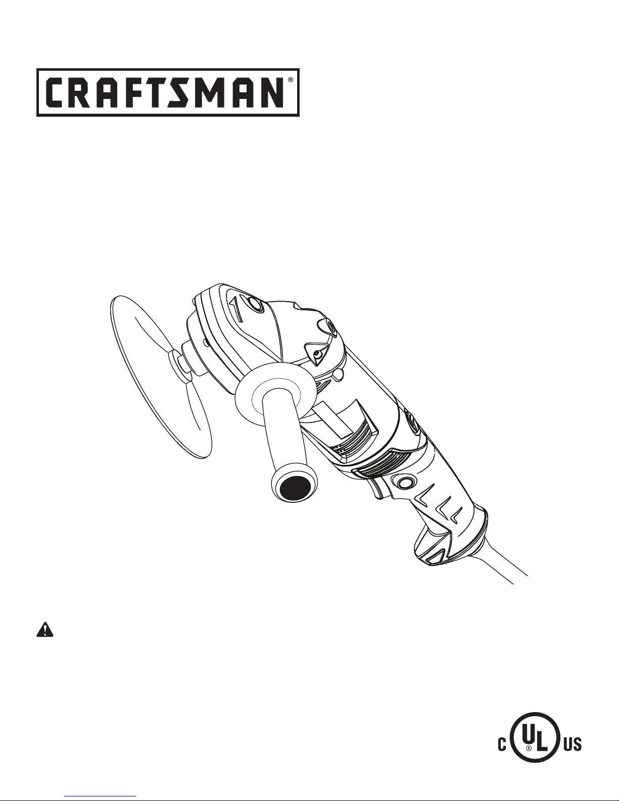
OPERATOR’S MANUAL
6 in. RIGHT ANGLE SANDER/POLISHER
DOUBLE INSULATED
Model No.
315.115060
WARNING: To reduce the risk of injury,
the user must read and understand the
operator’s manual before using this product.
Customer Help Line: 1-800-932-3188
Sears, Roebuck and Co., 3333 Beverly Rd., Hoffman Estates, IL 60179 USA
Visit the Craftsman web page: www.sears.com/craftsman
983000-859
1-03-06 (REV:00)
Save this manual for future reference
1
Page 2

TABLE OF CONTENTS
�� Warranty .......................................................................................................................................................................... 2
�� Introduction ..................................................................................................................................................................... 2
�� General Safety Rules .................................................................................................................................................... 3-4
�� Specific Safety Rules ....................................................................................................................................................... 4
�� Symbols ........................................................................................................................................................................5-6
�� Electrical .......................................................................................................................................................................... 7
�� Features ........................................................................................................................................................................... 8
���� Assembly ......................................................................................................................................................................... 9
��� Operation ....................................................................................................................................................................9-13
�� Maintenance .................................................................................................................................................................. 14
�� Accessories ................................................................................................................................................................... 14
�� Exploded View and Parts List ........................................................................................................................................ 15
� Parts Ordering/Service .....................................................................................................................................Back Page
WARRANTY
ONE-YEAR FULL WARRANTY ON CRAFTSMAN TOOL
If this Craftsman tool fails to give complete satisfaction within one year from date of purchase, RETURN IT TO ANY
SEARS STORE OR OTHER CRAFTSMAN OUTLET IN THE UNITED STATES FOR FREE REPLACEMENT.
If this Craftsman tool is used for commercial or rental purposes, this warranty applies for only 90 days from the date of
purchase.
This warranty gives you specific legal rights, and you may also have other rights which vary from state to state.
Sears, Roebuck and Co., Dept. 817 WA, Hoffman Estates, IL 60179
INTRODUCTION
This tool has many features for making its use more pleasant and enjoyable. Safety, performance, and dependability
have been given top priority in the design of this product making it easy to maintain and operate.
2
Page 3

GENERAL SAFETY RULES
WARNING: Read and understand all instruc-
tions. Failure to follow all instructions listed below,
may result in electric shock, fire and/or serious
personal injury.
SAVE THESE INSTRUCTIONS
WORK AREA
Keep your work area clean and well lit. Cluttered
benches and dark areas invite accidents.
Do not operate power tools in explosive atmo-
spheres, such as in the presence of flammable
liquids, gases, or dust. Power tools create sparks
which may ignite the dust or fumes.
Keep bystanders, children, and visitors away while
operating a power tool. Distractions can cause you to
lose control.
ELECTRICAL SAFETY
Double insulated tools are equipped with a polar-
ized plug (one blade is wider than the other). This
plug will fit in a polarized outlet only one way. If the
plug does not fit fully in the outlet, reverse the plug.
If it still does not fit, contact a qualified electrician
to install a polarized outlet. Do not change the plug
in any way. Double insulation
for the three-wire grounded power cord and grounded
power supply system.
Avoid body contact with grounded surfaces such
as
pipes, radiators, ranges, and refrigerators. There
is an increased risk of electric shock if your body is
grounded.
Don’t expose power tools to rain or wet conditions.
Water entering a power tool will increase the risk of
electric shock.
Do not abuse the cord. Never use the cord to carry
the tools or pull the plug from an outlet. Keep cord
away from heat, oil, sharp edges, or moving parts.
Replace damaged cords immediately. Damaged
cords increase the risk of electric shock.
When operating a power tool outside, use an outdoor
extension cord marked “W-A” or “W”. These cords
are rated for outdoor use and reduce the risk of electric
shock.
PERSONAL SAFETY
Stay alert, watch what you are doing and use com-
mon sense when operating a power tool. Do not
use tool while tired or under the influence of drugs,
alcohol, or medication. A moment of inattention while
operating power tools may result in serious personal
injury.
Dress properly. Do not wear loose clothing or
jewelry. Contain long hair. Keep your hair, clothing,
and gloves away from moving parts. Loose clothes,
jewelry, or long hair can be caught in moving parts.
eliminates the need
Avoid accidental starting. Be sure switch is off before
plugging in. Carrying tools with your finger on the switch
or plugging in tools that have the switch on invites
accidents.
Remove adjusting keys or wrenches before turning
the tool on. A wrench or a key that is left attached to a
rotating part of the tool may result in personal injury.
Do not overreach. Keep proper footing and balance
at all times. Proper footing and balance enables better
control of the tool in unexpected situations.
Use safety equipment. Always wear eye protection.
Dust mask, nonskid safety shoes, hard hat, or hearing
protection must be used for appropriate conditions.
Do not wear loose clothing or jewelry. Contain long
hair. Loose clothes, jewelry, or long hair can be drawn
into air vents.
Do not use on a ladder or unstable support. Stable
footing on a solid surface enables better control of the
tool in unexpected situations.
TOOL USE AND CARE
Use clamps or other practical way to secure and
support the workpiece to a stable platform. Holding
the work by hand or against your body is unstable and
may lead to loss of control.
Do not force tool. Use the correct tool for your ap-
plication. The correct tool will do the job better and
safer at the rate for which it is designed.
Do not use tool if switch does not turn it on or off.
Any tool that cannot be controlled with the switch is
dangerous and must be repaired.
Disconnect the plug from power source before
making any adjustments, changing accessories,
or storing the tool. Such preventive safety measures
reduce the risk of starting the tool accidentally.
Store idle tools out of the reach of children and
other untrained persons. Tools are dangerous in the
hands of untrained users.
Maintain tools with care. Keep cutting tools sharp
and clean. Properly maintained tools with sharp cut-
ting edges are less likely to bind and are easier to
control.
Check for misalignment or binding of moving parts,
breakage of parts, and any other condition that
may affect the tool’s operation. If damaged, have
the tool serviced before using. Many accidents are
caused by poorly maintained tools.
Use only accessories that are recommended by the
manufacturer for your model. Accessories that may
be suitable for one tool, may become hazardous when
used on another tool.
Keep the tool and its handle dry, clean and free
from oil and grease. Always use a clean cloth when
cleaning. Never use brake fluids, gasoline, petroleumbased products, or any strong solvents to clean your
tool. Following this rule will reduce the risk of loss of
control and deterioration of the enclosure plastic.
3
Page 4

GENERAL SAFETY RULES
SERVICE
Tool service must be performed only by qualified
repair personnel. Service or maintenance performed
by unqualified personnel may result in a risk of injury.
SPECIFIC SAFETY RULES
Accessories must be rated for at least the speed
recommended on the tool warning label. Wheels and
other accessories running over rated speed can fly apart
and cause injury.
Hold tool by insulated gripping surfaces when
performing an operation where the cutting tool may
contact hidden wiring or its own cord. Contact with
a “live” wire will make exposed metal parts of the cutting tool “live” and shock the operator.
Know your power tool. Read operator’s manual
carefully. Learn its applications and limitations, as
well as the specific potential hazards related to this
tool. Following this rule will reduce the risk of electric
shock, fire, or serious injury.
Always wear safety glasses. Everyday eyeglasses
have only impact-resistant lenses; they are NOT
safety glasses. Following this rule will reduce the risk
of serious personal injury.
Protect your lungs. Wear a face or dust mask if the
operation is dusty. Following this rule will reduce the
risk of serious personal injury.
Protect your hearing. Wear hearing protection dur-
ing extended periods of operation. Following this rule
will reduce the risk of serious personal injury.
Inspect tool cords periodically and, if damaged,
have repaired at your nearest Authorized Service
Center. Constantly stay aware of cord location.
Following this rule will reduce the risk of electric shock
or fire.
When servicing a tool, use only identical replace-
ment parts. Follow instructions in the Maintenance
section of this manual. Use of unauthorized parts or
failure to follow Maintenance Instructions may create a
risk of shock or injury.
Check damaged parts. Before further use of the
tool, a guard or other part that is damaged should
be carefully checked to determine that it will operate properly and perform its intended function.
Check for alignment of moving parts, binding of
moving parts, breakage of parts, mounting, and
any other conditions that may affect its operation. A guard or other part that is damaged should
be properly repaired or replaced by an authorized
service center. Following this rule will reduce the risk
of shock, fire, or serious injury.
Make sure your extension cord is in good condition.
When using an extension cord, be sure to use one
heavy enough to carry the current your product will
draw. A wire gauge size (A.W.G.) of at least 14 is
recommended for an extension cord 50 feet or less
in length. A cord exceeding 50 feet is not recommended. If in doubt, use the next heavier gauge.
The smaller the gauge number, the heavier the
cord. An undersized cord will cause a drop in line volt-
age resulting in loss of power and overheating.
Inspect for and remove all nails from lumber before
using this tool. Following this rule will reduce the risk
of serious personal injury.
Save these instructions. Refer to them frequently and
use them to instruct others who may use this tool. If
you loan someone this tool, loan them these instructions also.
WARNING: Some dust created by power sanding, sawing, grinding, drilling, and other construction activities
contains chemicals known to cause cancer, birth defects or other reproductive harm. Some examples of these
chemicals are:
• lead from lead-based paints,
• crystalline silica from bricks and cement and other masonry products, and
• arsenic and chromium from chemically-treated lumber.
Your risk from these exposures varies, depending on how often you do this type of work. To reduce your exposure
to these chemicals: work in a well ventilated area, and work with approved safety equipment, such as those dust
masks that are specially designed to filter out microscopic particles.
4
Page 5

SYMBOLS
Some of the following symbols may be used on this tool. Please study them and learn their meaning. Proper interpretation of these symbols will allow you to operate the tool better and safer.
SYMBOL NAME
V Volts Voltage
A Amperes Current
Hz Hertz Frequency (cycles per second)
W Watt Power
min Minutes Time
Alternating Current Type of current
Direct Current Type or a characteristic of current
n
o
.../min Per Minute Revolutions, strokes, surface speed, orbits etc., per minute
No Load Speed Rotational speed, at no load
Class II Construction Double-insulated construction
DESIGNATION/EXPLANATION
Wet Conditions Alert Do not expose to rain or use in damp locations.
Read The Operator’s Manual
Eye Protection
Safety Alert Precautions that involve your safety.
No Hands Symbol
No Hands Symbol
No Hands Symbol
No Hands Symbol
To reduce the risk of injury, user must read and understand
operator’s manual before using this product.
Always wear safety goggles or safety glasses with side shields and,
as necessary, a full face shield when operating this product.
Failure to keep your hands away from the blade will result in
serious personal injury.
Failure to keep your hands away from the blade will result in
serious personal injury.
Failure to keep your hands away from the blade will result in
serious personal injury.
Failure to keep your hands away from the blade will result in
serious personal injury.
Hot Surface
To reduce the risk of injury or damage, avoid contact with any
hot surface.
5
Page 6

SYMBOLS
The following signal words and meanings are intended to explain the levels of risk associated with this product.
SYMBOL SIGNAL MEANING
DANGER:
WARNING:
CAUTION
CAUTION
Indicates an imminently hazardous situation, which, if not avoided, will result
in death or serious injury.
Indicates a potentially hazardous situation, which, if not avoided, could result
in death or serious injury.
Indicates a potentially hazardous situation, which, if not avoided, may result in
minor or moderate injury.
(Without Safety Alert Symbol) Indicates a situation that may result in property
damage.
SERVICE
Servicing requires extreme care and knowledge and
should be performed only by a qualified service technician. For service we suggest you return the product to
your nearest AUTHORIZED SERVICE CENTER for repair.
When servicing, use only identical replacement parts.
WARNING:
WARNING: To avoid serious personal injury, do not
attempt to use this product until you read thoroughly
and understand completely the operator’s manual. If
you do not understand the warnings and instructions
in the operator’s manual, do not use this product.
Call Sears customer service for assistance.
The operation of any power tool can result in foreign objects being thrown into your eyes, which
can result in severe eye damage. Before beginning power tool operation, always wear safety
goggles or safety glasses with side shields and, when needed, a full face shield. We recommend
Wide Vision Safety Mask for use over eyeglasses or standard safety glasses with side shields.
Always use eye protection which is marked to comply with ANSI Z87.1.
SAVE THESE INSTRUCTIONS
6
Page 7

ELECTRICAL
DOUBLE INSULATION
Double insulation is a concept in safety in electric power
tools, which eliminates the need for the usual three-wire
grounded power cord. All exposed metal parts are
isolated from the internal metal motor components with
protecting insulation. Double insulated tools do not need
to be grounded.
WARNING: The double insulated system is
intended to protect the user from shock resulting
from a break in the tool’s internal insulation. Observe
all normal safety precautions to avoid electrical
shock.
NOTE: Servicing of a tool with double insulation requires
extreme care and knowledge of the system and should
be performed only by a qualified service technician. For
service, we suggest you return the tool to your nearest
authorized service center for repair. Always use original
factory replacement parts when servicing.
ELECTRICAL CONNECTION
This tool has a precision-built electric motor. It should be
connected to a power supply that is 120 volts, 60 Hz,
AC only (normal household current). Do not operate
this tool on direct current (DC). A substantial voltage drop
will cause a loss of power and the motor will overheat. If
the tool does not operate when plugged into an outlet,
double-check the power supply.
EXTENSION CORDS
When using a power tool at a considerable distance from
a power source, be sure to use an extension cord that has
the capacity to handle the current the tool will draw. An
undersized cord will cause a drop in line voltage, resulting
in overheating and loss of power. Use the chart to determine the minimum wire size required in an extension cord.
Only round jacketed cords listed by Underwriter’s Laboratories (UL) should be used.
When working outdoors with a tool, use an extension
cord that is designed for outside use. This type of cord is
designated with “WA” on the cord’s jacket.
Before using any extension cord, inspect it for loose or
exposed wires and cut or worn insulation.
**Ampere rating (on tool faceplate)
Cord Length Wire Size (A.W.G.)
25' 16 16 16 16 14 14
50' 16 16 16 14 14 12
100' 16 16 14 12 10 —
**Used on 12 gauge - 20 amp circuit
NOTE: AWG = American Wire Gauge
0-2.0 2.1-3.4 3.5-5.0 5.1-7.0 7.1-12.0 12.1-16.0
WARNING: Keep the extension cord clear of the
working area. Position the cord so that it will not get
caught on lumber, tools or other obstructions while
you are working with a power tool. Failure to do so
can result in serious personal injury.
WARNING: Check extension cords before each
use. If damaged replace immediately. Never use tool
with a damaged cord since touching the damaged
area could cause electrical shock resulting in serious
injury.
7
Page 8

FEATURES
PRODUCT SPECIFICATIONS
Disc Size/Polishing Bonnet ......................................... 6 in.
Speed Switch ........................................................2 Speed
Spindle Size ..................................................... 1/2-20 UNF
No Load Speed ....................... 1,400/min. and 1, 650/min.
Input ................................120 V, 60 Hz, AC only, 4.5 Amps
SPINDLE
LOCK
90˚ ROTATING
RUBBER
DISC
HANDLE
LOCK-ON
BUTTON
TWO-SPEED
SWITCH TRIGGER
SIDE
HANDLE
LIVE
TOOL
INDICATOR
Fig. 1
KNOW YOUR SANDER/POLISHER
See Figure 1.
The safe use of this product requires an understanding of
the information on the tool and in this operator’s manual
as well as a knowledge of the project you are attempting. Before use of this product, familiarize yourself with all
operating features and safety rules.
SIDE HANDLE
The provided side handle stabilizes your sander/polisher
and must be used during all operations. The side handle
can be mounted in three different positions.
LIVE TOOL INDICATOR
The live tool indicator is located on the handle of the
sander/polisher and indicates that the tool is connected to
a power supply.
LOCK-ON BUTTON
The lock-on button is convenient for continuous sanding or polishing for extended periods of time. Since the
sander/polisher has two speeds, the lock-on button can
lock-on at high or low speed.
90˚ ROTATING HANDLE
The handle rotates 90˚ to the left or right for ease of use.
SPINDLE LOCK
The spindle lock keeps the spindle from turning while
installing and removing bonnets and disks.
TWO-SPEED SWITCH TRIGGER
Your sander/polisher is equipped with a two-speed switch
trigger located in the handle. For low speed, depress the
trigger halfway. For full speed and power, depress the
trigger fully.
8
Page 9

FEATURES
UNPACKING
This product has been shipped completely assembled.
Carefully remove the tool and any accessories from the
box. Make sure that all items listed in the packing list
are included.
Inspect the tool carefully to make sure no breakage or
damage occurred during shipping.
Do not discard the packing material until you have
carefully inspected and satisfactorily operated the tool.
If any parts are damaged or missing, please call
1-800-932-3188 for assistance.
PACKING LIST
Sander/Polisher
Side Handle
Rubber Disc
Polishing Bonnet
Spanner Wrench
Spanner Nut
Operator’s Manual
WARNING: If any parts are damaged or missing
do not operate this tool until the parts are replaced.
Failure to heed this warning could result in serious
personal injury.
WARNING: Do not attempt to modify this tool
or create accessories not recommended for use
with this tool. Any such alteration or modification is
misuse and could result in a hazardous condition
leading to possible serious personal injury.
WARNING: Do not connect to power supply until
assembly is complete. Failure to comply could result
in accidental starting and possible serious injury.
INSTALLING THE SIDE HANDLE ASSEMBLY
See Figure 2.
� Unplug the sander/polisher.
Insert the handle assembly to the desired operating
position.
Securely tighten by turning the handle assembly
clockwise.
NOTE: The side handle must always be used to prevent
loss of control and prevent injury.
TO
LOOSEN
TO
TIGHTEN
Fig. 2
WARNING: Do not allow familiarity with tools
to make you careless. Remember that a careless
fraction of a second is sufficient to inflict serious
injury.
WARNING: Always wear safety goggles or safety
glasses with side shields when operating power
tools. Failure to do so could result in objects being
thrown into your eyes resulting in possible serious
injury.
WARNING: Do not wear loose clothing or jewelry
when operating this tool. They could get caught in
moving parts causing serious injury. Keep head away
from sander/polisher and sanding or polishing area.
Hair could be drawn into sander/polisher causing
serious injury.
OPERATION
WARNING: Do not hold the rubber disc with one
hand and use the power of the sander/polisher to
tighten the rubber disc on the spindle. The sander/
polisher could slip in your hand, or cause an
accident resulting in serious personal injury.
WARNING: Always unplug the tool when installing
or removing disks, adjusting settings, or when the
tool is not in use. Failure to unplug the tool may
result in accidental starting and serious personal
injury.
APPLICATIONS
You may use this tool for the purposes listed below:
Sanding on wood and wood product surfaces
Removing rust from and sanding steel surfaces
Polishing and buffing painted surfaces
9
Page 10

OPERATION
TWO-SPEED SWITCH TRIGGER
See Figure 3.
The sander/polisher is equipped with a two-speed switch
trigger located in the handle. To turn ON, depress switch
trigger. to turn OFF, release switch trigger. For low speed
sanding or polishing, depress switch trigger halfway. For
high speed sanding or polishing depress switch trigger all
the way. Be sure switch trigger is in OFF position before
connecting to power supply source.
LOCK-ON
BUTTON
Fig. 4
TWO-SPEED
SWITCH TRIGGER
Fig. 3
LOCK-ON BUTTON
See Figure 4.
This sander/polisher is equipped with a lock-on feature,
which is convenient for continuous sanding/polishing for
extended periods of time.
To lock-on:
Depress the switch trigger.
Push in and hold the lock-on button, located on the
side of the handle.
Release the switch trigger.
Release the lock-on button and the sander/polisher will
continue running.
To release the lock, depress and release the switch
trigger.
If the lock-on feature is engaged during use and the
sander/polisher becomes disconnected from the power
supply, disengage the lock-on feature immediately.
NOTE: Since the sander/polisher has two speeds, it is
possible to lock-on both speeds. To lock-on in low speed,
press two-speed switch trigger halfway and follow above
lock-on directions for lock-on sanding/polishing. To lockon at high speed, depress trigger fully and follow above
directions.
90˚ ROTATING HANDLE
See Figure 5.
The handle on the sander/polisher can rotate 90˚ to the left
or the right for ease of operation.
To adjust the 90˚ rotating handle:
Press and hold handle button.
Rotate the handle to the desired position and release
button.
NOTE: Make sure the push button on the 90˚ rotating
handle clicks into place when changing handle positions.
PUSH
BUTTON
TO ROTATE
HANDLE
Fig. 5
10
Page 11

OPERATION
SPINDLE LOCK
See Figure 6.
� Unplug the sander/polisher.
� To lock the spindle, depress and hold the spindle lock.
�� While keeping the lock depressed, rotate the disc
clockwise until the spindle clicks into a locked position
and will not rotate further.
� �To unlock, release the spindle lock.
SPANNER
WRENCH
TURN
CLOCKWISE
TO
TIGHTEN
SPANNER
NUT
TURN
COUNTERCLOCKWISE
TO
LOOSEN
To remove:
Unplug the sander/polisher.
Position the tool as shown in figure 6 and lock the
spindle lock.
Loosen spanner nut with the spanner wrench provided
by turning counterclockwise.
Remove spanner nut.
Turn rubber disc counterclockwise to remove.
Release the spindle lock.
SPANNER
WRENCH
SANDING
DISC
SPANNER
NUT
RUBBER
DISC
SPINDLE
LOCK
Fig. 6
INSTALLING/REMOVING RUBBER DISC
See Figures 6.
Unplug the sander/polisher.
Position the tool as shown in figure 6 and lock the
spindle lock.
Thread rubber disc, flat face up, onto spindle in a
clockwise direction. Turn until rubber disc shoulders on
the spindle.
Start spanner nut onto threaded spindle in a clockwise
direction.
Securely tighten spanner nut with the spanner wrench
provided.
Release the spindle lock.
SPINDLE
LOCK
INSTALLING/REMOVING SANDING DISC
See Figure 7.
Unplug the sander/polisher.
� Position the tool as shown in figure 7 and lock the spindle
lock.
� Center and place the sanding disc over the rubber
disc and start spanner nut onto threaded spindle in a
clockwise direction, into the center of the sanding disc.
� Securely tighten spanner nut with the spanner wrench
provided.
� Release the spindle lock.
To remove:
� Unplug the sander/polisher.
� Position the tool as shown in figure 7 and lock the
spindle lock.
� Loosen spanner nut with the spanner wrench provided
by turning counterclockwise.
� Remove spanner nut.
� Remove the sanding disk.
� Release the spindle lock.
NOTE: A sanding disc is not supplied.
11
Fig. 7
Page 12

OPERATION
INSTALLING/REMOVING POLISHING BONNET
See Figure 8.
Unplug the sander/polisher.
Remove the sanding disk if necessary.
� Securely retighten spanner nut with the spanner wrench
provided if necessary.
Slip polishing bonnet edges over rubber disc.
To remove, pull polishing bonnet edges over and off
rubber disc.
NOTE: Some polishes should be buffed while damp while
others must be allowed to dry; therefore, always check the
manufacturer’s label.
Tilt the tool so that the polishing bonnet is at a slight angle
to the work surface. Always start polishing at the top or
highest point and work down. This will prevent light dust
or polish film from being thrown upon completed section.
It also eliminates pulling the tool’s power cord over
sections already polished.
Surfaces that have an old film of wax or polish, or that
have not been polished or waxed for an extended period
of time, may require a second application. This is
especially true on oxidized surfaces. Heavily oxidized
surfaces should be cleaned with a commercial paste or
liquid cleaner before polishing or waxing.
WARNING: Check polishing bonnets before
each use. Make sure they are clean and free from
any loose particles or foreign objects that may be
embedded in the bonnet. Failure to do so could
cause these particles or objects to be thrown from
the tool resulting in possible serious injury.
PULL POLISHING
BONNET EDGES OVER
DISC TO INSTALL
Fig. 8
WARNING: Keep a firm grip on the tool with both
hands at all times. Failure to do so could result in
loss of control leading to possible serious injury.
POLISHING
See Figure 9.
When polishing, hold the sander/polisher firmly, allowing it
to operate freely without unnecessary pressure. The weight
of the tool alone will provide adequate pressure for polishing at top efficiency. For best results, always operate at low
speed when polishing.
Bonnets must be kept clean and free from grit, dirt, and
other abrasive particles. When bonnets become dirty and
clogged with polishing film, wash in lukewarm water with
a mild detergent. Allow bonnets to dry thoroughly before
reuse. Polish with a long sweeping motion, back and
forth, advancing along the surface to be polished. Do not
hold the tool in one spot or use a circular or spiral pattern.
This will cause swirls in the finish.
Spread a light coat of polish or wax over a small area.
Polish with the tool according to the manufacturer’s
instructions printed on the label of the polish or wax
container.
Fig. 9
12
Page 13

OPERATION
WARNING: To prevent loss of control and possible
serious personal injury, always operate the tool with
both hands, keeping one hand on the side handle.
SANDING
See Figure 10.
Clamp or otherwise secure the work to prevent it from
moving under your sander/polisher. Secure small workpieces
in a vise or use clamps to secure them to a workbench.
WARNING: Unsecured work could be thrown
towards the operator causing injury.
Hold the tool in front and away from you, keeping it clear
of the workpiece. Start the tool by depressing the switch
trigger and letting the motor build to its maximum speed.
Gradually lower sander/polisher to the workpiece at a
slight (5° to 8°) angle.
Do not attempt to hold the sanding disc flat on the
workpiece. Always keep the tool in motion moving over
the work, allowing it to operate freely without unnecessary pressure. The weight of the unit supplies adequate
pressure, so let the sanding disc and sander do the work.
Applying additional pressure only slows the motor, rapidly
wears sanding discs, and greatly reduces sander speed.
Excessive pressure will overload the motor, causing
possible damage from motor overheating, which can
result in inferior work. Any finish or resin on wood may
soften from the frictional heat.
Do not sand too long in one spot. This will cause uneven
sanding and gouging of the work.
Upon completion of a sanding operation, lift tool away
from work surface before turning off.
WARNING: Sanding disc must come to a complete
stop before setting tool down on workbench. Failure
to do so can cause the tool to be thrown from
workbench because of sanding disc rotation. This
could result in damage to the tool or possible serious
injury to the operator.
Fig. 10
SANDING DISC SELECTION
Selecting the correct size grit and type sanding disc is
an extremely important step in achieving a high quality
sanded finish. Aluminum oxide, silicon carbide, and other
synthetic abrasives are best for power sanding. Natural
abrasives, such as flint and garnet are too soft for
economical use in power sanding.
In general, coarse grit will remove the most material and
finer grit will produce the best finish in all sanding
operations.
The condition of the surface to be sanded will determine
which grit will do the job. If the surface is rough, start with
a coarse grit and sand until the surface is uniform.
Medium grit may then be used to remove scratches left by
the coarser grit and finer grit used for finishing the surface.
Always use the proper grit sanding disc, and not extra
pressure when sanding. Continue sanding with each grit
until surface is uniform.
13
Page 14

MAINTENANCE
WARNING: When servicing, use only identical
Craftsman replacement parts. Use of any other parts
may create a hazard or cause product damage.
WARNING: Always wear safety goggles or safety
glasses with side shields during power tool operation
or when blowing dust. If operation is dusty, also wear
a dust mask.
GENERAL MAINTENANCE
Avoid using solvents when cleaning plastic parts. Most
plastics are susceptible to damage from various types of
commercial solvents and may be damaged by their use.
Use clean cloths to remove dirt, dust, oil, grease, etc.
WARNING: Do not at any time let brake fluids,
gasoline, petroleum-based products, penetrating
oils, etc., come in contact with plastic parts.
Chemicals can damage, weaken or destroy plastic
which may result in serious personal injury.
ACCESSORIES
Electric tools used on fiberglass material, wallboard,
spackling compounds, or plaster are subject to
accelerated wear and possible premature failure because
the fiberglass chips and grindings are highly abrasive to
bearings, brushes, commutators, etc. Consequently, we
do not recommended using this tool for extended work on
these types of materials. However, if you do work with any
of these materials, it is extremely important to clean the
tool using compressed air.
LUBRICATION
All of the bearings in this tool are lubricated with a
sufficient amount of high grade lubricant for the life of
the unit under normal operating conditions. Therefore, no
further lubrication is required.
Only the parts shown on the parts list are intended to be
repaired or replaced by the customer. All other parts
should be replaced at a Sears Service Center.
Look for these accessories at Sears retail:
150 Grit Sanding Disc-Fine ........................................................................................................................................ 6 in.
100 Grit Sanding Disc-Medium .................................................................................................................................. 6 in.
60 Grit Sanding Disc-Coarse ...................................................................................................................................... 6 in.
40 Grit Sanding Disc-Very Coarse ............................................................................................................................. 6 in.
Other Assorted Sanding Disks
Polishing Bonnet
WARNING: Current attachments and accessories available for use with this tool are listed above. Do not use any
attachments or accessories not recommended by the manufacturer of this tool. The use of attachments or
accessories not recommended can result in serious personal injury.
14
Page 15

CRAFTSMAN SANDER/POLISHER – MODEL NUMBER
315.115060
The model number will be found on a plate attached to the motor housing. Always mention the model
number in all correspondence regarding your SANDER/POLISHER or when ordering repair parts.
SEE BACK PAGE FOR PARTS ORDERING INSTRUCTIONS
1
2
5
3
4
PARTS LIST
Key Part
No. Number Description Qty.
1 300188035 Side handle .....................................................................................................1
2 300588002 Rubber Disc ....................................................................................................1
3 691206001 Spanner Nut ....................................................................................................
4 630886001 Spanner Wrench ..............................................................................................1
5 900593001 * Polishing Bonnet .............................................................................................
983000859 Operator’s Manual
1
1
* Standard Hardware Item – May Be Purchased Locally
15
Page 16

® Registered Trademark / TM Trademark /SM Service Mark of Sears, Roebuck and Co.
® Marca Registrada /
TM
Marca de Fábrica / SM Marca de Servicio de Sears, Roebuck and Co.
MC
Marque de commerce / MD Marque déposée de Sears, Roebuck and Co. © Sears, Roebuck and Co.
Get it fixed, at your home or ours!
Your Home
For repair – in your home – of all major brand appliances,
lawn and garden equipment, or heating and cooling systems,
no matter who made it, no matter who sold it!
For the replacement parts, accessories and
owner’s manuals that you need to do-it-yourself.
For Sears professional installation of home appliances
and items like garage door openers and water heaters.
1-800-4-MY-HOME
®
(1-800-469-4663)
Call anytime, day or night (U.S.A. and Canada)
www.sears.com www.sears.ca
Our Home
For repair of carry-in items like vacuums, lawn equipment,
and electronics, call or go on-line for the location of your nearest
Sears Parts & Repair Center.
1-800-488-1222
Call anytime, day or night (U.S.A. only)
www.sears.com
To purchase a protection agreement (U.S.A.)
or maintenance agreement (Canada) on a product serviced by Sears:
1-800-827-6655 (U.S.A.) 1-800-361-6665 (Canada)
Para pedir servicio de reparación
a domicilio, y para ordenar piezas:
1-888-SU-HOGAR
SM
(1-888-784-6427)
Au Canada pour service en français:
1-800-LE-FOYER
MC
(1-800-533-6937)
www.sears.ca
16
 Loading...