

Page 1

Operator's Manual
LAWN TRACTO
16.5 HR* 42" Mower
Electric Start
6 Speed Transaxle
Model No.
917.28903
• Espa5ol, p. 33
This product has a low emission engine which operates
differently from previously built engines. Before you start the
engine, read and understand this Owner's Manual.
IMPORTANT:
Read and follow all Safety
Rules and Instructions before
operating this equipment.
Sears, Roebuck and Co., Hoffman Estates, IL 60179 U.S.A.
Visit our Craftsman website:www_sears.com/craftsman *As rated by the engine manufactu_rer
For answers to your questions about
this product, Call:
1=800=659-5917
Sears Craftsman Help Line
5 am - 5 pm, Mon - Sat
Page 2

Warranty .................................................. 2
Safety Rules ........................................... 3
Product Specifications ....................................6
AssemblyiPre-Operation ........................ 8
Operation .............................................. 11
Maintenance Schedule ....................................17
CRAFTSMAN LIMITED WARRANTY
TWO YEARS ON TRACTOR
When operated and maintained according to all supplied instructions, if this tractor fails
due to a defect in material or workmanship within two years from the date or purchase,
call 1-800-4-MY-HOME® to arrange for free repair°
During the first year of purchase, there will be no charge for warranty service in your home.
For your convenience, in-home warranty service will still be available after the first year
of purchase, but a trip charge wilt apply. This charge will be waived if you transport the
tractor to an authorized Craftsman drop-off location. For the nearest authorized location,
call I _800-4_MY-HOME®,
90 DAYS ON BATTERY
For ninety (90) days from date of purchase, if the battery included with this tractor is
defective in material or workmanship (our testing proves it will not hold a charge), it will be
replaced free of charge in your home.
This warranty covers ONLY defects in material and workmanship. Sears will NOT pay for:
Maintenance ..............................................................17
Service and Adjustments ...................... 22
Storage ................................................. 27
Troubleshooting .................................... 28
Sears Service ......................... Back Cover
• Expendable items that become worn during normal use, including but not limited to
blades, spark plugs, air cleaners, belts, and oil filters.
• Standard maintenance servicing, oil changes, or tune-ups.
• Tire replacement or repair caused by punctures from outside objects, such as nails,
thorns, stumps, or glass.
• Tire or wheel replacement or repair resulting from normal wear, accident, or improper
operation or maintenance°
• Repairs necessary because of operator abuse, including but not limited to damage
caused by towing objects beyond the capability of the tractor, impacting objects that
bend the frame or crankshaft, or over-speeding the engine.
• Repairs necessary because ofoperator negligence, including but not limited to, electrical
and mechanical damage caused by improper storage, failure to use the proper grade
and amount of engine oil, failure to keep the deck clear of flammable debris, or failure
to maintain the equipment according to the instructions contained in the operator's
manual.
• Engine (fuel system) cleaning or repairs caused by fuel determined to be contaminated or
oxidized (stale). In general, fuel should be used within 30 days of its purchase date.
• Normal deterioration and wear of the exterior finishes, or product label replacement.
Al! tractor and battery warranty coverage is void if this product is ever used for
commercial or rental purposes.
This warranty applies only while this product is within the United States.
This warranty gives you specific legal rights, and you may also have other rights which
vary from state to state.
Sears, Roebuck and Co,, Hoffman Estates, IL 60179
2
Page 3
DANGER: This cutting machine is capable of amputating hands and feet and throwing
objects. Failure to observethe following safety instructions could result in serious
injury or death.
_IbWARNIN G: In order to prevent accidental
starting when setting up, transporting, ad-
justing or making repairs, always disconnect
spark plug wire and place wire where itcan not
contact spark plug.
_WARNING: Do not coast down a hill in
neutral, you may lose control of the tractor.
_I_WARNING: Tow only the attachments
that are recommended by and comply with
specifications of the manufacturer of your
tractor. Use common sense when towing.
Operate only at the lowest possible speed
when on a slope. Too heavy of a load, while
on a slope, is dangerous. Tires can lose
traction with the ground and cause you to
lose control of your tractor.
_WARNING: Engine exhaust, some of its
constituents, and certain vehicle corn ponents
contain or emit chemicals known to the State
of California to cause cancer and birth defects
or other reproductive harm°
_WARNING: Batter,/posts, terminals and
related accessories contain lead and lead
compounds, chemicals known to the State of
California to cause cancer and birth defects
or other reproductive harm° Wash hands
after handling,
I. GENERAL OPERATION
. Read, understand, and follow all instruc-
tions on the machine and in the manual
before starting.
, Do not put hands or feet near rotating
parts or under the machine. Keep clear
of the discharge opening at all times.
, Only allow responsible adults, who are
familiar with the instructions, to operate
the machiner
• Clear the area of objects such as rocks,
toys, wire, etc,, which could be picked up
and thrown by the blades..
. Be sure the area is clear of bystanders
before operating. Stop machine if anyone
enters the area.
• Never carry passengers°
, Do not mow in reverse unless absolutely
necessary. Always look down and behind
before and while backing.
• Never direct discharged material toward
anyone_ Avoid discharging material
against a wall or obstruction_ Material may
ricochet back toward the operator. Stop the
blades when crossing gravel surfaces.
, Do not operate machine without the entire
grass catcher, discharge guard, or other
safety devices in place and working.
• Stow down before turning.
• Never leave a running machine unat-
tended. Always turn off blades, set park*
ing brake, stop engine, and remove keys
before dismounting,
• Disengage blades when not mowing_ Shut
off engine and wait for all parts to come
to a complete stop before cleaning the
machine, removing the grass catcher, or
unclogging the discharge guard.
• Operate machine only in daylight or good
artificial light.
• Do not operate the machine while under
the influence of alcohol or drugs.
o Watch for traffic when operating near or
crossing roadways.
• Use extra care when loading or unloading
the machine into a trailer or truck_
- Always wear eye protection when operat-
ing machine.
• Data indicates that operators, age 60
years and above, are involved in a large
percentage of riding mower-related inju-
ries. These operators should evaluate
their ability to operate the riding mower
safely enough to protect themselves and
others from serious injury.
, Follow the manufacturer's recommen-
dation for wheel weights or counter-
weights.
o Keep machine free of grass , leaves or
other debris build-up which can touch hot
exhaust / engine parts and burn° Do not
allow the mower deck to plow leaves or
other debris which can cause build-up to
occur. Clean any oil or fuel spillage before
operating or storing the machine. Allow
machine to cool before storage.
3
Page 4
U, SLOPE OPERATION
Slopes are a major factor related to loss of
control and tip-over accidents, which can
result in severe injury or death. Operation
on all slopes requires extra caution_ If you
cannot back up the slope or if you feel uneasy
on it, do not mow it.
• Mow up and down slopes, not across.
• Watch for holes, ruts, bumps, rocks, or
other hidden objects. Uneven terrain could
overturn the machine° Tall grass can hide
obstacles°
• Choose a low ground speed so that you
will not have to stop or shift while on the
slope_
• Do not mow on wet grass. Tires may lose
traction
Always keep the machine in gear when
going down slopes° Do not shift to neutral
and coast downhill°
• Avoid starting, stopping, or turning on a
slope, tfthe tires lose traction, disengage
the blades and proceed slowly straight
down the slope.
• Keep all movement on the slopes slow and
gradual. Do not make sudden changes
in speed or direction, which could cause
the machine to roll over,
. Use extra care while operating machine
with grass catchers or other attachments;
they can affect the stability ofthe machine°
Do no use on steep slopes°
• Do not try to stabilize the machine by
putting your foot on the ground.
° Do not mow near drop-offs, ditches, or
embankments. The machine could sud-
denly roll over if a wheel is over the edge
or if the edge caves in,
III. CHILDREN
Tragic accidents can occur if the operator
is not alert to the presence of children.
Children are often attracted to the machine
and the mowing activity. Never assume
that children will remain where you last
saw them.
• Keep children outofthe mowing areaand
in the watchful care of a responsible adult
other than the operator.
• Be alert and turn machine off if a child
enters the area.
• Before andwhile backing, look behind and
down for small children°
, Never carry children, even with the blades
shutoff, They may fall offand be seriously
injured or interfere with safe machine
operation, Children who have been given
rides in the past may suddenly appear in
the mowing area for another ride and be run
over or backed over by the machine°
. Never allow children to operate the ma-
chine_
• Use extra care when approaching blind
corners, shrubs, trees, or other objects
that may block your view of a child,
iV. TOWING
• Tow only with a machine that has a hitch
designed for towing. Do not attach towed
equipment except at the hitch point.
• Follow the manufacturer's recommenda-
tion for weight limits for towed equipment
and towing on slopes_
• Never allow children or others in or on
towed equipment_
• On slopes, the weight ofthetowed equip-
ment may cause loss of traction and loss
of control.
, Travel slowly and allow extra distance to
stop.
V. SERVICE
SAFE HANDLING OF GASOLINE
To avoid personal injury or property dam-
age, use extreme care in handling gasoline,
Gasoline is extremely flammable and the
vapors are explosive.
o Extinguish all cigarettes, cigars, pipes,
and other sources of ignition.
• Use only approved gasoline container.
• Never remove gas cap or add fuel with
the engine running. Allow engine to cool
before refueling.
° Never fuel the machine indoors,
• Never store the machine or fuel container
where there is an open flame, spark, or
pilot light such as on a water heater or
other appliances.
• Never fill containers inside a vehicle or
on a truck or trailer bed with plastic liner.
Always place containers on the ground
away from your vehicle when filling.
4
Page 5

, Remove gas-poweredequipment from the
truck or trailer and refuel it on the ground°
If this is not possible, then refuel such
equipmentwith a portable container, rather
than from a gasoline dispenser nozzle°
• Keep the nozzle in contact with the rim
of the fuel tank or container opening at
all times until fueling is complete, Do not
use a nozzle lock-open device.
• Iffuelis spilled on clothing, change clothing
immediately.
• Never overfill fuel tank. Replace gas cap
and tighten securely,
GENERAL SERVICE
• Never operate machine in a closed area_
• Keep all nuts and bolts tight to be sure the
equipment is in safe working condition°
• Never tamper with safety devices. Check
their proper operation regularly,
• Keep machine free of grass, leaves, or
otherdebris build-up, Clean oil or fuel spill-
age and remove any fuef_soaked debris.
Allow machine to cool before storing.
• If you strike a foreign object, stop and
inspectthe machine_ Repair, if necessary,
before restarting.
• Never make any adjustments or repairs
with the engine running.
• Check grass catcher components and the
discharge guard frequently and replace
with manufacturer's recommended parts,
when necessary.
• Mower blades are sharp. Wrap the blade
or wear gloves, and use extra caution when
servicing them.
• Check brake operation frequently.. Adjust
and service as required.
• Maintain or replace safety and instruction
labels, as necessary.
• Be sure the area is clear of bystanders
before operating° Stop machine if anyone
enters the area.
• Never carry passengers,
• Do not mow in reverse unless absolutely
necessary., Always look down and behind
before and while backing.
• Never carry children, even with the blades
shutoff. They may fall offand be seriously
injured or interfere with safe machine
operation. Children who have been given
rides in the past may suddenly appear in
the mowing area for another ride and be
run over or backed over by the machine.
• Keep children out of the mowing area and
in the watchful care of a responsible adult
other than the operator.
° Be alert and turn machine off if a child
enters the area,.
° Before and while backing, look behind and
down for small children.
• Mow up and down slopes (15 ° Max), not
across°
• Choose a low ground speed so thatyou will
not have to stop or shift while on the slope,
° Avoid starting, stopping, or turning on a
slope. If the tires lose traction, disengage
the blades and proceed slowly straight
down the slope°
• If machine stops while going uphill, disen-
gage blades, shift into reverse and back
down slowly.
• Do not turn on slopes unless necessary,
and then, turn slowly and gradually down-
hill, if possible,.
5
Page 6

PRODUCT SPECIFICATIONS
Gasoline Capacity 1.25 Unleaded
and Type: Regular
Oil Type SAE 30 (above 32°F)
(API-SG-SL): SAE 5W-,30(betow 32°F
Oil Capacity: W!Filter 56 oz.
W!O Filter 48 oz.
Spark Plug: Champion RCI2YC
(Gap: ,030")
Ground Speed
(MPH):
Charging System: 3 Amps Battery
Battery: Amp/Hr: 28
Blade Bolt Torque: 45-55 Fto Lbs.
CONGRATULATIONS on your purchase of a
new tractor, it has been designed, engineered
and manufactured to give you the best possible
dependability and performance.
Should you experience any problem you
cannot easily remedy, please contact a Sears
or other qualified service center. We have
competent, well-trained representatives
and the proper tools to service or repair
this tractor.
Please read and retain this manual, The
instructions will enable you to assemble
and maintain your tractor properly. Always
observe the "SAFETY RULES".
CUSTOMER RESPONSIBILITIES
• Read and observe the safety rules.
• Follow a regular schedule in maintaining,
caring for and using your tractor_
• Follow the instructions under "Mainte-
nance" and "Storage" sections of this
owner's manual.
_,WARNING: This tractor is equipped with
an internal combustion engine and should not
be used on or near any unimproved forest-
covered, brush-covered or grass-covered
land unless the engine's exhaust system is
equipped with a spark arrester meeting ap-
plicable local or state laws (if any). If a spark
arrester is used, it should be maintained in
effective working order by the operator.
Forward:
1st 1.1
2nd 1.4
3rd 2°2
4th 3.4
5th 4.3
6th 5.5
Reverse: 1.7
5 Amps Headlights
Min. CCA: 230
Case Size: U1R
In the state of California the above is required
by law (Section 4442 of the California Public
Resources Code). Other states may have
similar laws. Federal laws apply on federal
lands. A spark arrester for the muffler is
available through your nearest Sears service
center (See REPAIR PARTS manual).
REPAIR PROTECTION
AGREEMENTS
Congratulations on making a smart purchase.
Your new Craftsman@ product is designed
and manufactured for years of dependable
operation° But like all products, it may require
repair from time to time. That's when having
a Repair Protection Agreement can save you
money and aggravation.
Purchase a Repair Protection Agreement
now and protect yourself from unexpected
hassle and expense.
Here's what's included in the Agreement:
• Expert service by our 12,000 profesional
repair specialists
. Unlimited serviceand nochargeforparts
and labor on all covered repairs.
• Product replacement if your covered
product can't be fixed.
. Discount of 10% from regular price ofser-
vice and service-related parts not covered
by the agreement; also, 10% off regular
price of preventive maintenance check°
• Fast help by phone - phone support
from a Sears representative on products
requiring in-home repair, plus convenient
repair scheduling.
Once you purchase the Agreement, a
simple phone call is all that it takes for you
to schedule service. You can call anytime
day or night, or schedule a service appoint-
ment online_
Sears has over 12,000 professional repair
specialists, who have access to over 4.5
million quality parts and accessories. That's
the kind of professionalism you can count on
to help prolong the life of your new purchase
for years to come° Purchase your Repair
Protection Agreement today!
Some limitations and exclusions apply,
For prices and additional information call
1-800-827-6655.
SEARS INSTALLATION SERVICE
For Sears professional installation of home
appliances, garage door openers, water
heaters, and other major home items, in the
US.A. call 1-800.4-MY-HOME®
6
Page 7

fb
Steering Wheel
Steering
Wheel Insert
(1) Hex Bolt
5/t6-I8 x 4
[__:_ Steering Wheel
,1tlt11111t, Adapter
i I
Seat
(1) Large Flat Washer
(1) 5/16 Lock Washer
Steering
Boot
(1) Washer
Steering
Extension
Shaft
Keys
(2) Keys
I_(1) Knob
(1) Seat
(1) Oil Drain Tube
For Future Use
Slope Sheet
7
Page 8

'four new tractor has been assembled at the factory with the exception of those parts left
unassembled for shipping purposes. To ensure safe and proper operation of your tractor
all parts and hardware you assemble must be tightened securely_ Use the correct tools as
necessary to insure proper tightness.
TOOLS REQUIRED FOR ASSEMBLY
A socket wrench set will make assembly
easier. Standard wrench sizes you need
are listed below.
(1) 3/4"wrench (1) Pliers
(1) 1/2" wrench (1) Utility knife
(I) Tire pressure gauge
When right or left hand is mentioned in
this manual, it means when you are in the
operating position (seated behind the steer-
ing wheel).
TO REMOVE TRACTOR FROM
CARTON
UNPACK CARTON
1, Remove all accessible loose parts and
parts boxes from carton°
2. Cut along dashed lines on all four panels
of carton. Remove end panels and lay
side panels flat.
3, Check for any additional loose parts or
cartons and remove.
BEFORE REMOVING TRACTOR
FROM SKID
ATTACH STEERING WHEEL
ASSEMBLE EXTENSION SHAFT AND
BOOT
1. Slide extension shaft onto lower steer-
ing shaft.
2. Place tabs of steering boot over tab
slots in dash and push down to secure,
INSTALL STEERING WHEEL
3. Position front wheels of the tractor so
they are pointing straight forward.
4. Remove steering wheel adapter from
steering wheel and slide adapter onto
steering shaft extension,
5, Position steering wheel so cross bars
are horizontal (left to right) and slide
inside boot and onto adapter.
6. Assemble large flat washer, 5/I6 lock
washer, 5/16 hex bolt and tighten se-
curely,
7. Snap steering wheel insert into center
of steering wheel.
8. Remove protective materials from trac-
tor hood and grill
IMPORTANT: Check for and remove any
staples in skid that may puncture tires where
tractor is to roll off ski&
INSTALL SEAT
Adjust seat before tightening adjustment
knob,
1. Removeadjustment knob and flatwasher
securing seat to cardboard packing and
set aside for assembly of seat to trac-
tor.
2, Pivot seat upward and remove from the
cardboard packing, Remove the card-
board packing and discard.
3, Place seat on seat pan so head of shoul-
der bolt is positioned over large slotted
hole in pan,
4o Push down on seat to engage shoulder
bolt in slot and pull seat towards rear of
tractor_
5, Pivotseatand pan forward and assemble
adjustment knob and flatwasher loosely.
Do not tighten,
8
Page 9

6, Lower seat into operating position and
sit in seat,
7, Slide seat until a comfortable position
is reached which allows you to press
clutchtbrake pedal al! the way down,
8, Get off seat without moving its adjusted
position,
9, Raise seat and tighten adjustment knob
securely.
Seat
Seat Pan-,
ulder
Bolt
Fiat Washer
\.,
NOTE: You may now roll your tractor off
the skid° Follow the appropriate instruction
below to remove the tractor from the skid,
WARNING: Before starting, read, un-
derstand and follow all instructions in the
Operation section of this manual, Be sure
tractor is in a well-ventilated area. Be sure
the area in front of tractor is clear of other
people and objects°
TO ROLL TRACTOR OFF SKID
(See Operation section for location
and function of controls)
Io Press lift lever plunger and raise attach-
ment lift lever to its highest position,
2. Release parking brake by depressing
clutch/brake pedal.
3, Place gearshift lever in neutral (N) po-
sition,
4. Roll tractor forward off skid,
5. Remove banding holding the deflector
shield up against tractor,
Adj Knob
CHECK BATTERY
1. Lift seat pan to raised position,
NOTE: if this battery is put into service after
month and year indicated on label (label
located between terminals) charge battery
for minimum of one hour at 6-10 amps, (See
"BATTERY" in Maintenance section of this
manual for charging instructions),
Seat
Terminal
Label
Terminal
9
Page 10
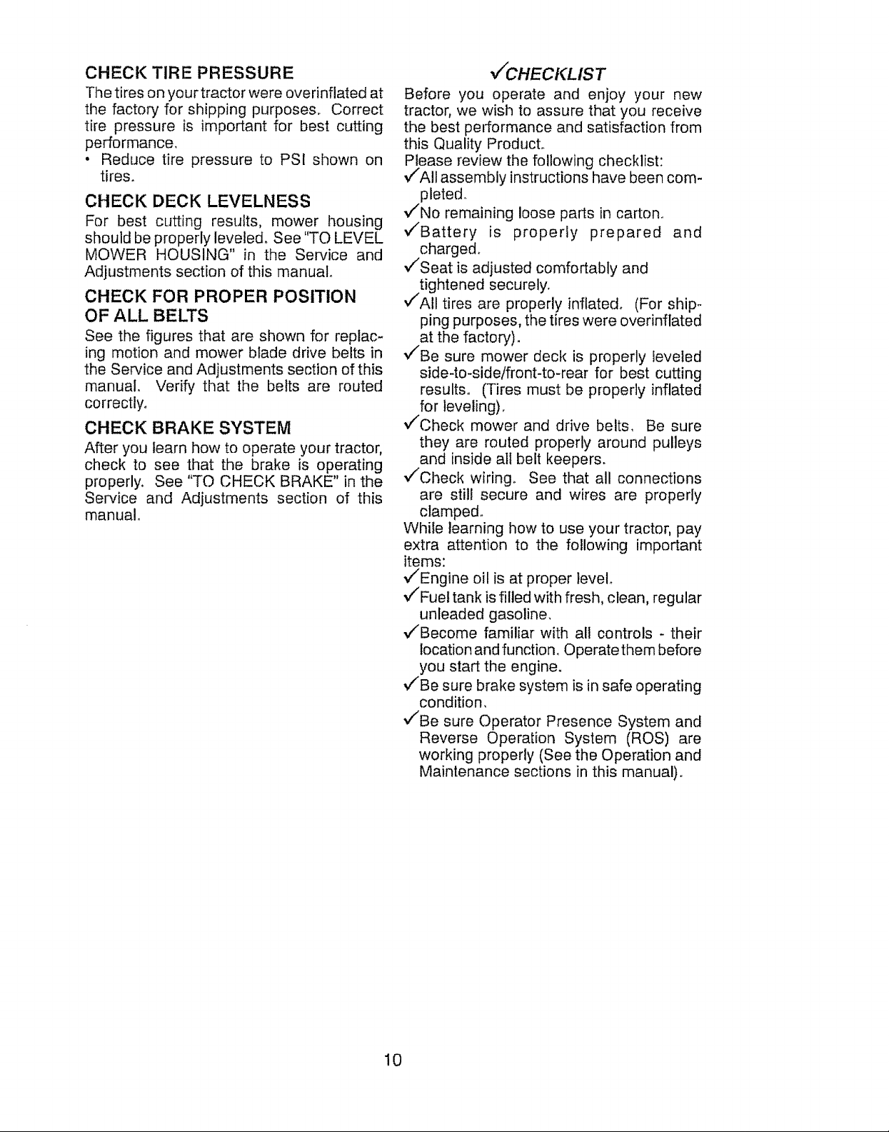
CHECK TIRE PRESSURE
The tires on your tractor were overinflated at
the factory for shipping purposes, Correct
tire pressure is important for best cutting
performance,
• Reduce tire pressure to PSI shown on
tires.
CHECK DECK LEVELNESS
For best cutting results, mower housing
should be properly leveled. See "TO LEVEL
MOWER HOUSING" in the Service and
Adjustments section of this manual°
CHECK FOR PROPER POSITION
OF ALL BELTS
See the figures that are shown for replac-
ing motion and mower blade drive belts in
the Service and Adjustments section of this
manual. Verify that the belts are routed
correctly.
CHECK BRAKE SYSTEM
After you learn how to operate your tractor,
check to see that the brake is operating
properly. See "TO CHECK BRAKE" in the
Service and Adjustments section of this
manual.
v/CHECKLIST
Before you operate and enjoy your new
tractor, we wish to assure that you receive
the best pe=t:ormance and satisfaction from
this Quality Product.
Please review the following checklist:
,/'All assembly instructions have been com-
pleted.
,/'No remaining loose parts in carton.
,/'Battery is properly prepared and
charged.
,/'Seat is adjusted comfortably and
tightened securely.
,/'All tires are properly inflated° (For ship-
ping purposes, the tires were overinflated
at the factory).
'/'Be sure mower deck is properly leveled
side-to-side/front-to-rear for best cutting
results_ (Tires must be properly inflated
for leveling).
v/Check mower and drive belts, Be sure
they are routed properly around pulleys
and inside all belt keepers.
v/Check wiring° See that all connections
are still secure and wires are properly
clamped.
While learning how to use your tractor, pay
extra attention to the following important
items:
,/'Engine oil is at proper level.
v/Fuel tank is filled with fresh, clean, regular
unleaded gasoline,
,/Become familiar with all controls - their
location and function. Operate them before
you start the engine.
•/Be sure brake system is in safe operating
condition,
,/"Be sure Operator Presence System and
Reverse Operation System (ROS) are
working properly (See the Operation and
Maintenance sections in this manual).,
10
Page 11
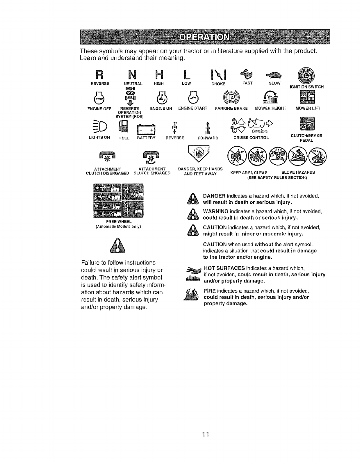
These symbols may appear on your tractor or in literature supplied with the product°
Learn and understand their meaning.
R N H L IXi '@
REVERSE NEUTRAL H_GH LOW CHOKE FAST SLOW
IGNITION SWITCH
ENGINE OFF REVERSE ENGINE ON ENGINE START PARKING BRAKE MOWER HEtGHT
LIGHTS ON
OPERATION
SYSTEM (ROS)
FUEL BATTERY
REVERSE FORWARD
CRUISE CONTROL
®@®@@
ATTACHMENT ATTACHMENT
CLUTCH DISENGAGED CLUTCH ENGAGED
FREE WHEEL
(Aulemetic Models only)
Failure to follow instructions
could result in serious injury or
death. The safety alert symbol
is used to identify safety inform-
ation about hazards which can
result in death, serious injury
andlor property damage,
DANGER, KEEP HANDS
AND FEET AWAY
DANGER indicates a I_azard which, if not avoided,
&
will result in death or serious injury.
WARNING indicates a hazard which, ii'not avoided,
&
could result in death or serious injury.
CAUTION indicates a hazard which, i[ not avoided,
might result in minor or moderate injury.
CAUTION when used without the alert symbol,
indicates a situation that could result in damage
to the tractor and/or engine.
HOT SURFACES indicates a hazard which,
,_t,ttltltt,_,
if not avoided, could result tn death, serious injury
and/or property damage,
FIRE indicates a hazard which, if not avoided,
could result in death, serious injury and!or
property damage.
KEEP AREA CLEAR SLOPE HAZARDS
(SEE SAFETY RULES SECTION)
MOWER LIFT
CLUTCH/BRAKE
PEDAL
11
Page 12

KNOW YOUR TRACTOR
READ THIS OWNER'S MANUAL AND SAFETY RULES BEFORE OPERATING YOUR
TRACTOR
Compare the illustrations with your tractor to familiarize yourself with the locations of
various controls and adjustments. Save this manual for future reference.
Throttle/Choke k\\_
Control , , _"_-'_k_-" ""_"
Light Switch ,"
Clutch/Brake
Pedal
Attachment
Clutch Lever Ignition Switch
ROS "ON" Position
Lift Lever
Plunger
Lift Lever
o Height
Adjustment
Indicator
Parldng Brake Lever
Gearshift Lever
Our tractors conform to the applicable safety standards of the
American National Standards Institute,
ATTACHMENT CLUTCH LEVER - Used to
engage the mower blades, or other attach-
ments mounted to your tractor.
ATTACHMENT LIFT LEVER - Used to raise,
lower, and adjust the mower deck or other
attachments mounted to your tractor.
CLUTCH/BRAKE PEDAL _ Used for de-
clutching and braking the tractor and starting
the engine.
GEARSHIFT LEVER - Selects the speed
and direction of tractor.
IGNITION SWITCH - Used for starting and
stopping the engine.
LIFT LEVER PLUNGER - Used to release
attachment lift lever when changing its
position.
LIGHT SWITCH - Turns the headlights on
and off.
PARKING BRAKE LEVER - Locks clutch!
brake pedal into the brake position.
THROTTLE!CHOKE CONTROL- Used for
starting and controlling engine speed.
REVERSE OPERATION SYSTEM (ROS)
"ON" POSITION -Allows operation of
mower deck or other powered attachment
while in reverse,
12
Page 13

The operation of any tractor can result in foreign objects thrown into
the eyes, which can result in severe eye damage. Always wear safety
glasses or eye shields while operating your tractor or performing any
adjustments or repairs. We recommend a wide vision safety mask over
spectacles or standard safety glasses.
HOW TO USE YOUR TRACTOR
TO SET PARKING BRAKE
Your tractor is equipped with an operator
presence sensing switch. When engine is
running, any attempt by the operator to leave
the seat without first setting the parking brake
will shut off the engine.
1. Depress clutch/brake pedal all the way
down and hold.
2. Pull parking brake lever up and release
pressure from clutch/brake pedal, Pedal
should remain in brake position. Make
sure parking brake will hold tractor se-
cure,
Throttle! Attachment Clutch Lever
Choke "Engaged" Position
Control"\ .._ __/
\ ---4_. _._ --_ Ignition Key
"-_'--,...z,_ ___// ulsengagea
"Brake" Position
Position _, ',, X._', _ij_/Parking Brake
_.._ '. _k_: _/ "Engaged'
' '\ _, _,,'-_-_;_ Position
\\_ _.." .f_J_ Gearshift
f ,,n_,.,,',,.... ,4, Lever
Clutch/Brake ,-,,o=-u=u_,-,
Pedal Position
STOPPING
MOWER BLADES -
• To stop mower blades, move attachment
clutch lever to disengaged position.
GROUND DRIVE-
• To stop ground drive, depress clutch/brake
pedal a!l the way down.
• Move gearshift lever to neutral iN) po-
sition.
ENGINE -
• Move throttle control between half and full
speed (fast) position.
NOTE: Failure to move throttle control
between half and full speed (fast) posi-
tion, before stopping, may cause engine to
"backfire"°
• Turn ignition key to "STOP" position and re-
move key.. Always remove key when leav-
ing tractor to prevent unauthorized use.
, Never use choke to stop engine.
IMPORTANT: Leaving the ignition switch in
any position other than "STOP" will cause
the battery to discharge and go dead,
NOTE: Undercertain conditionswhentractor
is standing idle with the engine running, hot
engine exhaust gases may cause "brown-
ing" of grass. To eliminate this possibility,
always stop engine when stopping tractor
on grass areas°
_CAUTION: Always stop tractor com-
pletely, as described above, before leaving
the operator's position.
TO USE THROTTLE CONTROL
Always operate engine at full speed (fast).
• Operating engine at less than full speed
(fast) reduces engine's operating effi-
ciency.
• Full speed (fast) offers the best mower
performance.
TO MOVE FORWARD AND BACKWARD
The direction and speed of movement is
controlled by the gearshift lever°
1. Start tractor with clutch!brake pedal
depressed and gearshift lever in neutral
(N) position.
2. Move gearshift lever to desired po-
sition.
3, Slowly release clutch/brake pedalto start
movemento
IMPORTANT: Bring tractor to a complete
stop before shifting or changing gears.
Failure to do so will shorten the useful life
of your transaxle,
TO ADJUST MOWER CUTTING HEIGHT
The position of the attachment lift lever
determines the cutting height.
• Grasp lift lever.
° Press plunger with thumb and move lever
to desired position.
The cutting height range is approximately
1-1/2to 4% The heights are measured from
the ground to the blade tip with the engine
not running. These heights are approximate
and may vary depending upon soil condi-
tions, height of grass and types of grass
being mowed.
13
Page 14
. The average lawn should be cut to ap-
proximately 2-1/2 inches during the cool
season and to over 3 inches during hot
months. For healthier and better looking
lawns, mow often and after moderate
growth.
- For best cutting performance, grass over
6 inches in height should be mowed twice.
Make the first cut relatively high; the sec-
ond to desired height.
TO OPERATE MOWER
"Your tractor is equipped with an operator
presence sensing switch_ Any attempt
by the operator to leave the seat with the
engine running and the attachment clutch
engaged will shut off the engine, You must
remain fully and centrally positioned in the
seat to prevent the engine from hesitating or
cutting off when operating your equipment
on rough, rolling terrain or hills.
1, Select desired height of cut.
2, Start mower blades by engaging at-
tachment clutch control.
TO STOP MOWER BLADES -
disengage attachment clutch control.
_CAUTION" Do not operate the mower
without either the entire grass catcher, on
mowers so equipped, or the deflector shield
in place.
_, /Attachment Lift
)2 Z'LeverHighPosition
Attachment k.L_c, tl _ ::
Clutch Lever -_:[_ _h'_i. ?L---___q,_,
'Eng.aged_._ ._C?Jf- iii ./, Pos"ition
Position- -__--/ i_J _//(_
"_'_: ,/_Deflector
OPERATING 1N REVERSE
"Your tractor is equipped with a Reverse
Operation System (ROS)_ Any attempt by
the operator to travel in the reverse direc-
tion with the attachment clutch engaged will
shut off the engine unless the ignition key is
placed in the ROS "ON" position°
_WARNING: Backing up with the at-
tachment clutch engaged while mowing is
strong ly discouraged. Turning the ROS "ON",
to allow reverse operation with the attach-
ment clutch engaged, should only be done
when the operator decides it is necessary to
reposition the machine with the attachment
engaged. Do not mow in reverse unless
absolutely necessary°
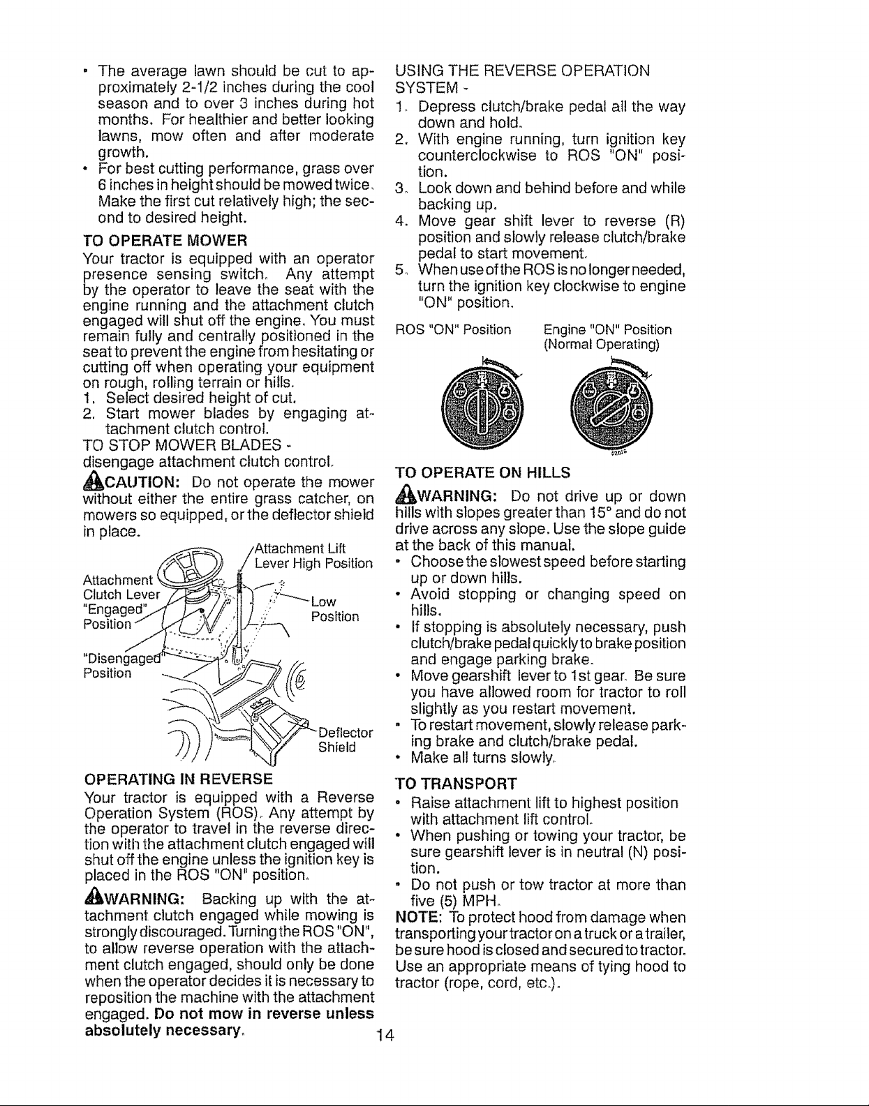
USING THE REVERSE OPERATION
SYSTEM -
1, Depress clutch/brake pedal atl the way
down and hold.
2. With engine running, turn ignition key
counterclockwise to ROS "ON" posi-
tion.
3. Look down and behind before and while
backing up.
4. Move gear shift lever to reverse (R)
position and slowly release clutch/brake
pedal to start movement.
5. When useofthe ROS is no longer needed,
turn the ignition key clockwise to engine
"ON" position.
ROS "ON" Position
TO OPERATE ON HILLS
_WARNING: Do not drive up or down
hills with slopes greater than 15 ° and do not
drive across any slope. Use the slope guide
at the back of this manual.
• Choosetheslowestspeed before starting
up or down hills.
• Avoid stopping or changing speed on
hills.
• If stopping is absolutely necessary, push
clutch/brake pedal quickly to brake position
and engage parking brake.
• Move gearshift lever to Ist gear Be sure
you have allowed room for tractor to roll
slightly as you restart movement.
. To restart movement, slowly release park-
ing brake and clutch/brake pedal.
• Make all turns slowly.
TO TRANSPORT
o Raise attachment lift to highest position
with attachment lift control
• When pushing or towing your tractor, be
sure gearshift lever is in neutral (N) posi-
tion.
= Do not push or tow tractor at more than
five (5) MPH°
NOTE: To protect hood from damage when
transporting your tractor on a truck or atrailer,
be sure hood is closed and secured to tractor°
Use an appropriate means of tying hood to
tractor (rope, cord, etc.).
Engine "ON" Position
(Normal Operating)
14
Page 15

TOWING CARTS AND OTHER ATTACH-
MENTS
Tow only the attachments that are recom-
mended by and comply with specifications
of the manufacturer of your tractor. Use
common sense when towing° Too heavy of
a load, while on a slope, is dangerous. Tires
can lose traction with the ground and cause
you to lose control of your tractor.
BEFORE STARTING 'THE ENGINE
CHECK ENGINE OIL LEVEL
The engine inyour tractor has been shipped,
from the factory, already filled with summer
weight oil.
1.. Check engine oil with tractor on level
ground.
2, Remove oil fill cap/dipstick and wipe
clean, reinsert the dipstick and screw cap
tight, wait for a few seconds, remove and
read oil level. If necessary, add oil until
"FULE' mark on dipstick is reached. Do
not overt_ill,
• For cold weather operation you should
change oil for easier starting (See the oil
viscosity chart in the Maintenance section
of this manual).
• To change engine oil, see the Mainte-
nance section in this manual.
ADD GASOLINE
• Fill fuel tank to bottom of filler neck. Do
not overfill, Use fresh, clean, regular
unleaded gasoline with a minimum of
87 octane. (Use of leaded gasoline will
increase carbon and lead oxide deposits
and reduce valve life) oDo not mix oil with
gasoline_ Purchasefuel in quantitiesthat
can be used within 30 days to assure fuel
freshness.
_CAUTION: Wipe off any spilled oil or
fuel. Do not store, spill or use gasoline near
an open flame.
IMPORTANT: When operating in temper-
atures below 32°F(00C), use fresh, clean
winter grade gasoline to help insure good
cold weather starting.
CAUTION: Alcohol blended fuels (called
gasohol or using ethanol or methanol) can
attract moisture which leads to separation
and formation of acids during storage. Acidic
gas can damage the fuel system of an engine
while in storage. To avoid engine problems,
the fuel system should be emptied before
storage of 30 days or longer, Drain the gas
tank, start the engine and let it run until the
fuel lines and carburetor are empty. Use fresh
fuel next season. See Storage Instructions
for additional information, Never use engine
or carburetor cleaner products inthe fuel tank
or permanent damage may occur.
TO START ENGINE
When starting the engine for the first time or
if the engine has run out of fuel, it will take
extra cranking time to move fuel from the
tank to the engine
1. Sit on seat in operating position, depress
clutch/brake pedal and set parking
brake°
2o Place gear shift lever in neutral (N) posi-
tion.
3. Move attachment clutch to disengaged
position.
4. Move throttle control to choke position.
NOTE: Before starting, read the warm and
cold starting procedures below.
5. Insert key into ignition and turn key
clockwise to start position and release
key as soon as engine starts. Do not run
starter continuously for more than fifteen
seconds per minute, if the engine does
not start after several attempts, move
throttle control to fast position, wait a
few minutes and try again. If engine still
does not start, move the throttle control
back to the choke position and retry.
WARM WEATHER STARTING (50 ° F and
above)
6o When engine starts, move the throttle
control to the fast position.
- The attachments and ground drive can
now be used, If the engine does not
accept the load, restart the engine and
allow it to warm up for one minute using
the choke as described above.
15
Page 16
COLD WEATHER STARTING ( 50 ° F and
below)
6. When engine starts, leave throttle control
in choke position until engine warms up
and begins to run roughly° Once rough
running begins, immediately move the
throttle control to the fast position° Engine
warm-up may take from several seconds
to several minutes (the colder the tem-
perature, the longer the warm-up)o
o The attachments can also be used during
the engine warm-up period.
NOTE: tf at a high altitude (above 3000
feet) or in cold temperatures (below 32 F)
the carburetor fuel mixture may need to be
adjusted for best engine performance (see
"TO ADJUST CAR BUR ETOR" inthe Service
and Adjustments section of this manual)_
MOWING TIPS
. Mower should be properly leveled for best
mowing performance See "TO LEVEL
MOWER HOUSING" in the Service and
Adjustments section of this manual
• The left hand side of mower should be
used for trimming
, Drive so that clippings are discharged onto
the area that has already been cut Have
the cut areato the right of the tractor, This
will result in a more even distribution of
clippings and more uniform cutting
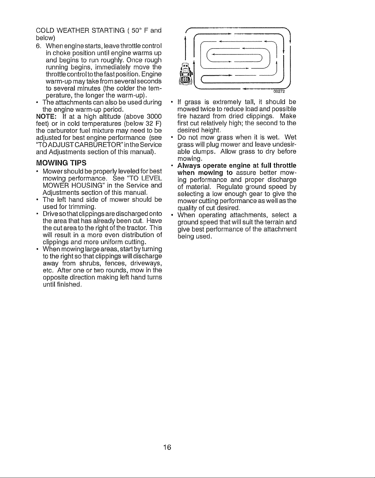
• When mowing large areas, start by turning
to the right so that clippings will discharge
away from shrubs, fences, driveways,
etc° After one or two rounds, mow in the
opposite direction making left hand turns
until finished°
f
m ,,_.
b,-
00272
• If grass is extremely tall, it should be
mowed twice to reduce load and possible
fire hazard from dried clippings. Make
first cut relatively high; the second to the
desired height.
• Do not mow grass when it is wet. Wet
grass will plug mower and leave undesir-
able clumps, Allow grass to dry before
mowing.
• Always operate engine at full throttle
when mowing to assure better mow-
ing performance and proper discharge
of material Regulate ground speed by
selecting a low enough gear to give the
mower cutting performance as well as the
quality of cut desired.
• When operating attachments, select a
ground speed that will suit the terrain and
give best performance of the attachment
being used,
16
Page 17

MAINTENANCE BEFORE EVER',, EVERY _VE.V EveRY EVE._" BEFORE
SCHEDULE EACH ,g 25 _0 lO0 SEASON STORAGE
Check Bra!_.eOpera!ion _ _/"
T'Check TirePressure _' 6/ ........
Check for Loose Fasteners 6/ .... 6/' 6/
A ChecldReptace Mower Blades f,_3
T iLubrication Chart
Level
O Check . , ,
_j 3hange Engine Oil (withoul oil {ilter)_ .......................... 6/'_,2 6/Dtean Air Filler 6/2
Battery
Clean Ballerl arid Termir_als - ] _/' .................
Check TraRsa×le Cooling ] !_'
Check Mower Levell*less . , 6##'
Check V:Bel[s .................................. 6/
3h,eck En,gtne,Oi{ Level _4'
3bange Eng![!e 0]! {with oll Iilter)
use .ou_s HOURS HOURS HOU.S
G SIRen Air Screen 6/_
1 _nspect Muffler/Spark Attester
N Replace Ott Filler, (tf equipped) ...... :!: ......................
E _lea_l Engine Coo|lag Fins ................. _/.._
Replace Spark Plug I_ " _
Replace Air Filler Paper Cartridge _//2
Replace Fuel Filter
1 - Change more or:ten when operating under a heavy lead or
in high ambient lernperalures,
2 - Service more often when operating in di_y or dusty send]liens
GENERAL RECOMMENDATIONS
3 - Replace blades mere ellen when mewing in sandy so_l
4. Not requb'ed if equipped wilh matrltenance4ree ballery
LUBRICATION CHART
The warranty on this tractor does not cover
items that have been subjected to operator
abuse or negligence,, To receive full value
(2_')Spindle --
Zerk
from the warranty, operator must maintain
tractor as instructed in this manual
Some adjustments will need to be made pe-
riodically to properly maintain your tractor°
_"2_')Front Wheel
Bearing
Zerk
At least once a season, check to see if
you should make any of the adjustments
described in the Service and Adjustments
section of this manual.
At least once a year you should replace
the spark plug, clean or replace air filter,
and check blades and belts for wean A
new spark plug and clean air filter assure
proper air-fuel mixture and help your en-
gine run better and last longer.
1, SAE 30 or 10w30 Motor Oil
2, General Purpose Grease
3. Refer to Maintenance "ENGINE" Section
BEFORE EACH USE
I. Check engine oil level.
2. Check brake operation.
3. Check tire pressure.
4. Check operator presence and
ROS systems for proper operation,
5. Check for loose fasteners.
IMPORTANT: Do not oil or grease the pivot
points which have special nylon bearings.
Viscous lubricants will attract dust and dirt
that will shorten the life of the self4ubricating
bearings, lfyou feel they must be lubricated,
use only a dry, powdered graphite type lu-
bricant sparingly.
17
)indle
Front Wheel
g Zerk
Gearshift
Pivots
Page 18

TRACTOR
Alwaysobservesafetyruleswhenperforming
anymaintenance,
BRAKEOPERATION
Iftractorrequiresmorethanfive (5)feetto
stopat highestspeedin highestgearon a
level,dry concreteor pavedsurface,then
brakemustbecheckedandadjusted_(See
"TO CHECKBRAKE"in the Serviceand
Adjustmentssectionofthismanual).
TIRES
• Maintainproper air pressurein all tires
(Seesidesoftirefor properPSI).
• Keeptiresfree ofgasoline,oil, or insect
controlchemicalswhichcanharmrubber.
• Avoid stumps,stones,deep ruts,sharp
objectsandotherhazardsthatmaycause
tiredamage.
NOTE;Tosealtirepuncturesandprevent
flattiresdueto slowleaks,tiresealantmay
be purchasedfromyourlocal partsdealer.
Tiresealantalso preventstire dry rot and
corrosion°
OPERATORPRESENCESYSTEMAND
REVERSEOPERATIONSYSTEM(ROS)
Be sure operator presenceand reverse
operationsystemsareworkingproperly, If
yourtractordoesnotfunctionasdescribed,
repairthe problemimmediately.
• The engineshouldnot start unlessthe
brakepedal is fully depressed,and the
attachmentclutchcontrolis inthe disen-
gagedposition.
CHECK OPERATOR PRESENCE
SYSTEM
• Whentheengineis running,anyattempt
bythe operatortoleavethe seatwithout
firstsettingtheparkingbrakeshouldshut
offtheengine.
• Whenthe engineis runningandthe at-
tachmentclutchisengaged,anyattempt
bythe operatorto leavetheseatshould
shutoffthe engine.
• Theattachmentclutchshouldneveroper-
ateunlesstheoperatorisinthe seat.
CHECK REVERSEOPERATION(ROS)
SYSTEM
, Whentheengineisrunningwiththeignition
switchintheengine"ON"positionandthe
attachmentclutchisengaged,anyattempt
bythe operatortogo intoreverseshould
shutofftheengine.
ROS "ON" Position
• When the engine is running with the ignition
switch in the ROS "ON" position and the
attachment clutch is engaged, any attempt
by the operator to shift into reverse should
NOT shut off the engine.
BLADE CARE
For best results mower blades must be kept
arp. Replace bent or damaged blades.
CAUTION: Use only a replacement
blade approved by the manufacturer of your
tractor. Using a blade not approved by the
manufacturer of your tractor is hazardous,
could damage your tractor and void your
warranty°
BLADE REMOVAL
1. Raise mower to highest position to alIow
access to blades.
NOTE: Protect your hands with gloves
and/or wrap blade with heavy cloth.
2. Remove blade bolt by turning counter-
clockwise°
3. Install new blade with stamped "THIS
SIDE UP" facing deck and mandrel
assembly.
IMPORTANT: To ensure proper assembly,
center hole in blade must align with star
on mandrel assembly.
4. Install and tighten blade bolt securely
(45-55 FL Lbs. torque).
Blade
(Sl
Center Hole [_
IMPORTANT: Special blade bolt is heat
treated..
Engine "ON" Position
(Normal Operating)
Mandrel
Assembly
I8
Page 19

BATTERY
Your tractor has a battery charging system
which is sufficient for normal user However,
periodic charging of the battery with an au-
tomotive charger will extend its lifeo
• Keep battery and terminals clean.
• Keep battery bolts tight,
• Keep small vent holes open.
• Recharge at 6-10 amperes for 1 hour.
NOTE: The original equipment battery on
your tractor is maintenance free° Do not
attempt to open or remove caps or covers.
Adding or checking level of electrolyte is
not necessary.
TO CLEAN BATTERY AND TERMINALS
Corrosion and dirt on the battery and termi-
nals can cause the battery to "leak" powen
1,, Disconnect BLACK battery cable first
then RED battery cable and remove
battery from tractor°
2_ Rinse the battery with plain water and
dry.
3. Clean terminals and battery cable ends
with wire brush until bright°
4. Coat terminals with grease or petroleum
jelly.
5. Reinstall battery (See "REPLACING
BATTERY" in the SERVICE AND AD-
JUSTMENTS section of this manual).
TRANSAXLE COOLING
Keep transaxle free from build-up of dirt and
chaff which can restrict cooling.
V-BELTS
Check V-belts for deterioration and wear after
100 hours of operation and replace if neces-
sary. The belts are not adjustable, Replace
belts if they begin to slip from wear.
ENGINE
LUBRICATION
Only use high quality detergent oi! rated with
API service classification SG-SL. Select the
oil's SAE viscosity grade according to your
expected operating temperature.
S_,E_iscosi_GRADES
TEMPERATURE RANGi_ At,rI'ICtPATED 8 EFORE NEXT OIL CHANGE
NOTE: Although multi-viscosity oils (5W30,
10W30 etc.) improve starting in cold weather,
the oils will result in increased oil consumption
when used above 32°E Check your engine
oil level more frequently to avoid possible
engine damage from running low on oil.
Change the oil after every 50 hours of opera-
tion or at least once a year if the tractor is
not used for 50 hours in one yean 19
Check the crankcase oil level before starting
the engine and after each eight (8) hours of
operation. Tighten oil fill cap/dipstick se-
curely each time you check the oil level,
TO CHANGE ENGINE OIL
Determine temperature range expected
before oil change All oil must meet API
service classification SG-SL,
t
Be sure tractor is on level surface,
o
Oil wilt drain more freely when warm.
Catch oil in a suitable container,
1.
Remove oil fill cap/dipstick. Be careful
not to allow dirt to enter the engine when
changing oil.
,
Remove yellow cap from end of drain
valve and install the drain tube onto the
fitting°
Oil Drain Valve
Closed and
Locked
Yellow
_ Drain
Cap
Tube
3. Unlock drain valve by pushing inward
slightly and turning counterclockwise.
4. To open, pull out on the drain valve,
5. After oil has drained completely, close and
lock the drain valve by pushing inward
and turning clockwise until the pin is in
the locked position as shown.
6, Remove the drain tube and replace the
cap onto the end of the drain valve.
7, Refill engine with oil through oil fill dipstick
tube. Pour slowly. Do not overfill, For
approximate capacity see "PRODUCT
SP ECIFICATIONS"section ofthis manual.
8. Use gauge on oil fill cap/dipstick for
checking level. For accurate reading,
tighten dipstick cap securely onto the
tube before removing dipstick° Keep oil
at "FULl" line on dipstick. Tighten cap
onto the tube securely when finished,
ENGINE OIL FILTER
Replace the engine oil filter every season
or every other oil change if the tractor is
used more than 100 hours in one year.
Page 20
IN-LINE FUEL FILTER
The fuel filter should be replaced once each
season. If fuel filter becomes clogged, ob-
structing fuel flow to carburetor, replacement
is required.
1. With engine cool, remove filter and plug
fuel line sections,.
2, Place new fuel filter in position in fuel line
with arrow pointing towards carburetor.
3_ Be sure there are no fuel line leaks and
clamps are properly positioned.
4. Immediatelywipe up any spilled gasoline.
p_._, Clamp
Clam ,,
AIR FILTER
"four engine wilt not run properly using a dirty
air filter. Replace pre-cleaner after' every 25
hours of operation or every season. Service
paper cartridge every 100 hours ofoperation
or every season, whichever occurs firsL
Service air cleaner more often under dusty
conditions_
1. Put! upon airfiltercoverhandle and rotate
towards engine.
2. Remove cover.
3. Carefully remove air filter cartridge and
pre-cleaner from base.
4. Clean base carefully to prevent debris
from falling into carburetor,
NOTE: If very dirty or damaged, replace
cartridge.
5_ Place new pre-cleaner and cartridge
firmly in base,
6. Align tabs on cover with slots in blower
housing and replace cover.
7. Hook handle on cover and push down
on handle to close.
I Filter
CLEANING
• Clean engine, battery, seat, finish, etc. of
ait foreign matter.
• Keep finished surfaces and wheels free
of all gasoline, oil, etc°
• Protect painted surfaces with automotive
type wax_
We do not recommend using a garden hose
or pressure washer to clean your tractor
unless the engine and transmission are
covered to keep water out. Water in engine
or transmission will shorten the useful life of
your tractor. Use compressed air or a leaf
blower to remove grass, leaves and trash
from tractor and mower.
MUFFLER
Inspect and replace corroded muffler and
spark arrester (if equipped) as it could create
a fire hazard and!or damage.
SPARK PLUG(S)
Replace spark plug(s) at the beginning of
each mowing season or after every 100
hours of operation, whichever occurs first,
Spark plug type and gap setting are shown
in "PRODUCT SPECIFICATIONS" section
of this manual.
CLEAN AIR SCREEN
Air screen must be kept free of dirt and chaff
to prevent engine damage from overheating.
Clean with a wire brush or compressed air to
remove dirt and stubborn dried gum fibers°
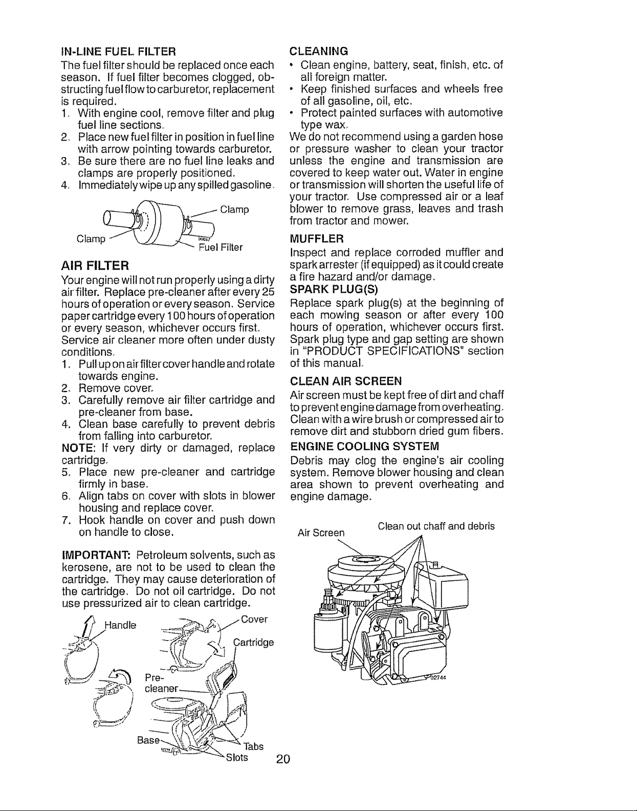
ENGINE COOLING SYSTEM
Debris may clog the engine's air cooling
system° Remove blower housing and clean
area shown to prevent overheating and
engine damage.
Air Screen
Clean out chaff and debris
IMPORTANT: Petroleum solvents, such as
kerosene, are not to be used to clean the
cartridge. They may cause deterioration of
the cartridge. Do not oil cartridge. Do not
use pressurized air to clean cartridge°
_.r_ Handle -_;->'._
;_7 Cover
,_' Cartridge
?J
i_{_._._ ",, cieaner_
Base_
_'_ Tabs
_-Slots
744
20
Page 21

WARNING: TO AVOID SERIOUS INJURY, BEFORE PERFORMING ANY
SERVICE OR ADJUSTMENTS:
1. Depress clutch!brake pedal fully and set parking braker
2. Place gearshift lever in neutral (N) position°
3. Place attachment clutch in "DISENGAGED" position°
4o Turn ignition key to "STOP" and remove key,
5. Make sure the blades and all moving parts have completely stopped.
6. Disconnect spark plug wire from spark plug and place wire where it cannot
come in contact with plug.
TRACTOR
TO REMOVE MOWER
Mower will be easier to remove from the
right side of tractor.
I. Place attachment clutch in "DISEN-
GAGED" position.
2. Move attachment lift lever forward to
lower mower to its lowest position,
3. Roll belt off engine pulley.
4_ Remove small retainer spring, and re-
move clutch spring off pulley boll
5. Remove large retainer spring, slide col-
lar off and push housing guide out of
bracket.
6. Disconnect anti-sway bar from chassis
bracket by removing retainer spring,
7 Disconnect suspension arms from rear
deck brackets by removing retainer
springs.
8. Disconnect front links from deck by re-
moving retainer springs.
9. Raise lift lever to raise suspension arms.
Slide mower out from under tractor.
IMPORTANT: If an attachment other than the
mower deck is to be mounted on the tractor,
remove the front links and hook the clutch
spring Into square hole in frame.
TO INSTALL MOWER
1. Raise attachment lift lever to its highest
position_
2o Slide mower under tractor with deflector
shield to right side of tractor.
3. Lower lift lever to its lowest position.
4_ Connect front links to mower deck and
secure with retainer springs,,
5. Connect suspension arms to rear deck
brackets and secure with retainer
springs.
6o Connect anti-sway bar to chassis bracket
and secure with retainer spring.
7_ Push clutch cable housing guide into
bracket, slide collar onto guide and secure
with large retainer spring.
8o Place flat washer and clutch spring on
idler pulley bolt and secure with small
retainer spring.
9_ Install belt onto engine pulley.,
Small Retainer S
Clutch Spring
Anti-Sway
Housing
Guide
Large Retainer Spring
Small Retainer Spring
Clutch
Bracket
Front Link
Retainer Springs
Both Sides)
Deflector Shield
21
Page 22

TO LEVEL MOWER HOUSING
Adjust the mower' while tractor is parked on
level ground or driveway. Make sure tires are
properly inflated (See side of tire for proper
PSI). If tires are over or underinflated, you
will not properly adjust your mower.
SID E-TO-S IDE ADJUSTMENT
• Raise mower to its highest position.
- At the midpoint of both sides of mower,
measure height from bottom edge of
mower to ground. Distance 'A" on both
sides of mower should be the same or
within 1/4" of each other.
• tf adjustment is necessary, make adjust-
ment on one side of mower only.
. To raise one side of mower, tighten lift link
adjustment nut on that side.
- To lower one side of mower, loosen lift link
adjustment nut on that side..
NOTE: Each full turn of adjustment nut will
change mower height about 1/8"o
- Recheck measurements after adjusting.
FRONT-TO-BACK ADJUSTM ENT
Bottom edge Bottom edge of
of mower to __ _--.-q mo_vyerto ground
ground ,.\ [ /
* To raise frontofmower, loosen nut"F"from
trunnion on both front links, Tighten nut
"E" on both front links an equal number
of turns, The two front links must remain
equal in length,
. When distance "D" is t/8" to 1/2" lower
at front than rear, tighten nut "F" against
trunnion on both front links°
. Recheck side-to-side adjustment.
,_° __.. Mandre,
Both Frontt_nks Should beE qual in Length
Nut "_ _ Nut "E"
_ Suspension Arm
Lift Link
Adjustment Nut _"_
IMPORTANT: Deck must be level side-to
side. lfthe following front-to-back adjustment
is necessary, be sure to adjust both front
links equally so mower will stay level side-
to-side.
To obtain the best cutting results, the mower
housing should be adjusted so that the front is
approximately 1/8"to 1/2" lower than the rear
when the mower is in its highest position.
Check adjustment on right side of tractor.
Measure distance "D" directly in front and
behind the mandrel at bottom edge of mower
housing as shown.
• Before making any necessary adjust-
ments, check that both front links are equal
in length.
• If links are not equal in length, adjust one
link to same length as other linko
• To lower front of mower loosen nut "E"
on both front links an equal number of
turns.
* When distance "D" is 1/8" to I/2" lower
at front than rear, tighten nuts "F" against
trunnion on both front links. 22
Page 23

TO REPLACE MOWER BLADE DRIVE
BELT
The mower blade drive belt may be replaced
without tools, Park the tractor on level sur-
face. Engage parking brake_
BELT REMOVAL -
1_ Remove mower from tractor (See "TO
REMOVE MOWER" in this section of
manual),
2. Work belt off both mandrel pulleys and
idler pulleys.
3. Pull belt away from mower,
BELT INSTALLATION -
1_ Work belt around both mandrel pulleys
and idler pulleys
2o Make sure belt is in all pulley grooves
and inside all belt guides.
3, Install mower (See "To Install Mower" in
this section of this manual)_
Mandrel
Pulley
Mandrel
Pulley
Idler Pulleys
TO REPLACE MOTION DRIVE BELT
Park the tractor on level surface, Engage
parking brake. For assistance, there is a
belt installation guide decal on bottom side
of left footrest.
BELT REMOVAL -
1. Remove mower (See "TO REMOVE
MOWER" in this section of manual)°
NOTE: Observe entire motion drive belt and
position of al! belt guides and keepers,
2, Remove belt from stationary idler and
clutching idler.
3. Remove belt downward from around
engine pulley°
4o Pull belt slack toward rear of tractor.
Remove belt upwards from transaxle
pulley by deflecting belt keepers°
5. Remove belt from center span keeper
and pull belt away from tractor.
BELT INSTALLATION
1o Carefully work new belt down between
transaxle belt keepers and onto the input
pulley°
2o Slide belt into the center span keeper°
3, Pull belt toward front of tractor and roll
around the top groove of engine pulley°
4, Install belt through stationary idler and
clutching idler.
5_ Make sure belt is in all pulley grooves
and inside all belt guides and keepers,
6,_ Install mower (See "TO INSTALL MOW-
ER" in this section of manual),
TO CHECK BRAKE
If tractor requires more than five (5) feet to
stop at highest speed in highest gear on a
level, dry concrete or paved surface, then
brake must be service&
"You may also check brake by:
1. Park tractor on a level, dry concrete or
paved surface, depress clutch/brake
pedal all the way down and engage
parking brake.
2. Place gear shift lever in neutral position.
The rear wheels must lock and skid when
you try to manually push the tractor forward.
If the rear wheels rotate, then the brake
needs to be serviced. Contact a Sears or
other qualified service center.
Engine
Clutching
Stationary Idler
Transaxle
Pulle,
Center
:_an
Keeper
23
Page 24

TRANSAXLE GEAR SHIFT LEVER NEU-
TRAL ADJUSTMENT
The transaxle should be in neutral when the
gear shift lever is in neutral (N) (lock gate)
position. The adjustment is preset at the
factory; however, if adjustment is needed,
proceed as follows:
1, Make sure transaxle is in neutral (N).
NOTE: When the tractor rear wheels move
freely, the transaxle is in neutral°
2. Loosen adjustment bolt in front of the
right rear wheel°
3_ Position the gear shift lever in the neutral
(N) position,
4, Tighten adjustment bolt securely.
NOTE: If additional clearance is needed to
get to adjustment bolt, move mower deck
height to the lowest position,
Neutral Lock Gate
Gearshift, Lever_ _
TO REMOVE WHEEL FOR REPAIRS
!. Block up axle securely.
2_ Remove axle cover, retaining ring and
washers to allow wheel removal (rear
wheels have a square key - Do not
lose).
3, Repair tire and reassemble.
NOTE: On rear wheels only: align
grooves in rear wheel hub and axle, Insert
square key°
4. Replace washers and snap retaining
ring securely in axle groove.
5. Replace axle cover.
NOTE: To seal tire punctures and prevent
flat tires due to slow leaks, purchase and
use tire sealant from Sears, Tire sealant
also prevents tire dry rot and corrosion°
Washers
Retaining
Ring
Axle \'_
Cover
/" -_., _ Adjustment Bolt
TO ADJUST STEERING WHEEL ALIGN-
MENT
tf steering wheel cross bars are not horizontal
(left to right) when wheels are positioned
straight forward, remove steering wheel
and reassemble with crossbars horizontal,
Tighten securely,
FRONT WHEEL TOE-IN!CAMBER
The front wheel toe-in and camber are not
adjustable on your tractor. If damage has
occurred to affect the front wheel toe-in or
camber, contact a Sears or other qualified
service center.
!
Square Key
(Rear Wheel Only)
TO START ENGINE WITH A WEAK
BATTERY
,_WARNING: Lead-acid batteries generate
explosive gases. Keep sparks, flame and
smoking materials away from batteries.
Always wear eye protection when around
batteries_
If your battery is too weak to start the engine, it
should be recharged, (See "BATTERY" in the
MAINTENANCE section of this manual),
If "jumper cables" are used for emergency
starting, follow this procedure:
IMPORTANT: Your tractor is equipped with
a 12 volt system. The other vehicle must also
be a 12 volt system. Do not use your tractor
battery to start other vehicles°
TO ATTACH JUMPER CABLES -
I. Connectone end ofthe RED cabletothe
POSITIVE (+) terminal of each battery(A-
B), taking care not to short against tractor
chassis.
2. Connect one end of the BLACK cable
to the NEGATIVE (-) terminal (C) of fully
charged battery.
3. Connect the other end of the BLACK
cable (D) to good chassis ground, away
from fuel tank and battery.
24
Page 25

TO REMOVECABLES,REVERSE
ORDER-
1. BLACKcablefirstfromchassisand
thenfromthefullychargedbattery,
2, REDcablelastfrombothbatteries°
WeakorDead FullyCharged
Battery Battery
REPLACINGBATTERY
_WARNING: Donotshortbatterytermi-
nalsbyallowingawrenchoranyotherobject
tocontactbothterminalsatthesametime,
Before connectingbattery,removemetal
bracelets,wristwatchbands,rings,etc.
Positiveterminalmustbeconnectedfirstto
preventsparkingfrom accidentalground-
ing.
1. Liftseatpanto raisedposition,,
2, DisconnectBLACK battery cable first
then RED battery cable and carefully
removebatteryfromtractor.
3. Installnewbatterywithterminalsinsame
positionasold battery°
4. FirstconnectREDbatterycabletoposi-
tive (+)terminalwith hexboltandkeps
nut as shown. Tightensecurely.Slide
terminalcoveroverterminal
5, Connect BLACK grounding cable to
negative(-)terminalwithremaininghex
boltandkepsnut.Tightensecurely.
3 Replacebulb in holderand push bulb
holdersecurelybackintotheholeinthe
backsideofthe grill.
4, Closehood.
INTERLOCKSAND RELAYS
Looseor damagedwiringmaycauseyour
tractortorunpoorly,stoprunning,orprevent
itfromstarting.
, Checkwiring° See electricalwiringdia-
graminthe RepairPartssection°
TOREPLACEFUSE
Replacewith20ampautomotive4ypeplug-
infuse_Thefuse holderis located behind
the dash.
TO REMOVE HOOD AND GRILL AS-
SEMBLY
1o Raise hoo&
2. Unsnap headlight wire connector.
3_ Stand in front of tractor. Grasp hood at
sides, tilt toward engine and lift off of
tractor.
4_ When replacing hood, be sure to recon-
nect the headlight wire connector.
(/ .... _"\ Hood
\_ x
Headlight Wire
Connector
Seat
Label
Terminal
(Red)
Cable Negative (Black)
Cable
TO REPLACE HEADLIGHT BULB
1, Raise hood.
2. Pull bulb holder out of the hole in the
backside of the grill. 25 position,
ENGINE
Maintenance, repair, or replacement of the
emission control devices and systems, which
are being done atthe customers expense, may
be performed by any non-road engine repair
establishment or individual° Warranty repairs
must be performed by an authorized engine
manufacturer's service outlet,
TO ADJUST THROTTLE CONTROL
CABLE
The throttle control has been preset at the
factory and adjustment should not be neces-
sary. Check adjustment as described below
before loosening cable, If adjustment is
necessary, proceed as follows:
1. With engine not running, move throttle
control lever from slow to choke position,
Slowly move lever from choke to fast
Page 26

2. Checkthatholes'A" ingovernorcontrol
lever and hole in governor plate line-
up. If holes '_' are not aligned, loosen
clamp screw and move throttle cable until
holes are aligned. Tighten clamp screw
securely°
Governor Control Lever Governor
_--_. _,:_ c,
Holes 'At'-'P'_'_/_J_llb,_l _ Throttle
TO ADJUST CARBURETOR
NOTE: The carburetor on this engine is
low emission. It is equipped with an idle
fuel adjusting needle with a limiter cap,
which allows some adjustment within the
limits allowed by the cap. Do not attempt
to remove the limiter cap. Tile limiter cap
cannot be removed without breaking the
adjusting needle,
The carburetor has been preset at the fac-
tory and adjustment should not be neces-
saryo However, minor adjustment may be
required to compensate for differences in
fuel, temperature, altitude or load. If the
carburetor does need adjustment, proceed
as follows:
In general, turning idle mixture valve in
(clockwise) decreases the supply of fuel to
the engine giving a leaner fuel/air mixture°
Turning the idle mixture valve out (counter-
clockwise) increases the supply offuel to the
engine giving a richer fuel/air mixture,
IMPORTANT: Damage to the needle valve
and the seat in carburetor may result if screw
is turned in too tight.
PRELIMINARY SETTING
'I. Aircleanerassembty must be assembled
to the carburetorwhen making carburetor
adjustments°
2. Be sure the throttle control cable is ad-
justed properly (see above).
' i
[ _;I Clamp _b_jl_,_j Cable
"-- '_/J Screw
Control Ptate
FINAL SETTING -
1. Start engine and allow to warm for five
minutes. Make final adjustments with
engine running and shift/motion control
lever in neutral (N) position°
2. Move throttle control lever to slow posi-
tiono With finger, rotate and hold throttle
lever against idle speed screw. Turn idle
speed screw to attain 1750 RPMo
3. While still holding throttle lever against
idle speed screw, turn idle mixture
valve full travel clockwise then counter-
clockwise until engine runs rough, TiJrn
valve to a point midway between those
two positions, Release throttle lever,
ACCELERATION TEST -
4, Move throttle control lever from slow
to fast position, If engine hesitates or
dies, turn idle mixture valve out (coun-
terclockwise) 1/8 turn. Repeat test and
continue to adjust, if necessary, until
engine accelerates smoothly.
High speed stop is factory adjusted. Do not
adjust - damage may resulL
IMPORTANT'; Never tamperwiththe engine
governor, which is factory set for proper
engine speed. Overspeeding the engine
above the factory high speed setting can be
dangerous. If you thinkthe engine-governed
high speed needs adjusting, contact aSears
or other qualified service center, which has
proper equipment and experience to make
any necessary adjustments,
Idle Speed r _ ''"_."'°'" Throttle
Screw _--_ Lever
C
Idle Mixture Valve _
With Limiter
26
Page 27

Immediately prepare your tractor for storage
at the end of the season or if the tractor will
not be used for 30 days or more.
_IbWARNING: Never store the tractor with
gasoline in the tank inside a building where
fumes may reach an open flame or spark.
Allow the engine to cool before storing in
any enclosure.
TRACTOR
Remove mower from tractor for winter
storage. When mower is to be stored for a
period of time, clean it thoroughly, remove
all dirt, grease, leaves, etc. Store in a clean,
dry area.
1, Clean entire tractor (See "CLEANING"
in the Maintenance section of this
manual),
2, Inspect and replace belts, if necessary
(See belt replacement instructions in the
Service and Adjustments section of this
manual).
3. Lubricate as shown in the Maintenance
section of this manual.
4. Be sure that all nuts, bolts and screws
are securely fastened, inspect moving
parts for damage, breakage and wear.
Replace if necessary,
5. Touch up all rusted or chipped paint
surfaces; sand lightly before painting.
BATTERY
• Fully charge the battery for storage,
• After a period of time in storage, battery
may require recharging.
• To help prevent corrosion and power
leakage during long periods of storage,
battery cables should be disconnected
and battery cleaned thoroughly (see "TO
CLEAN BATTERY AND TERMINALS"
in the Maintenance section of this man-
ual).
. Aftercleaning, leave cables disconnected
and place cables where they cannot come
in contact with battery terminals°
• If battery is removed from tractor for
storage, do not store battery directly on
concrete or damp surfaces°
ENGINE
FUEL SYSTEM
IMPORTANT: It is important to prevent
gum deposits from forming in essential fuel
system parts such as carburetor, fuel hose,
or tank during storage. Also, alcohol blended
fuels (called gasohol or using ethanol or
methanol) can attract moisture which leads
to separation and formation of acids during
storage. Acidic gas can damage the fuel
system of an engine while in storage°
• Empty the fuel tank by starting the engine
and letting it run until the fuel lines and
carburetor are empty.
. Never use engine or carburetor cleaner
products in the fuel tank or permanent
damage may occur,
• Use fresh fue! next season.
NOTE: Fuel stabilizer is an acceptable al-
ternative in minimizing the formation of fuel
gum deposits during storage. Add stabilizer
to gasoline in fuel tank or storage container.
Always follow the mix ratio found on stabilizer
container. Run engine at least 10 minutes
after add ing stabilizer to allow the stabilize r to
reach the carburetor° Do not empty the gas
tank and carburetor if using fuel stabilizer.
ENGINE OIL
Drain oil (with engine warm) and replace
with clean engine oil. (See "ENGINE" in the
Maintenance section of this manual),
CYLINDER(S)
1. Remove spark plug(s).
2. Pour one ounce of oil through spark plug
hole(s) into cylinder(s).
3. Turn ignition key to "START" position for
a few seconds to distribute oil.
4. Replace with new spark plug(s).
OTHER
• Do not store gasoline from one season to
another.
• Replaceyourgasoline can ifyour can starts
to rust. Rust and/or dirt in your gasoline
will cause problems°
• If possible, store your tractor indoors and
cover itto give protection from dust and dirt.
• Cover your tractor with a suitable protec-
tive cover that does not retain moisture.
Do not use plastic. Plastic cannot breathe
which allows condensation to form and will
cause your tractor to rust.
IMPORTANT: Never cover tractor while
engine and exhaust areas are still warm.
27
Page 28

TROUBLESHOOTING CHART:
See appropriate section in manual unless directed to Sears service center
PROBLEM
CAUSE
I
CORRECTION
-J,
Will not start
Will not start
1
Out of fuel
2
Engine not "CHOKED" properly.
3
Engine flooded r
4
Bad spark plug.
5
Dirty air filter°
6
Dirty fuel filter.
7
Water in fuel.
8
Loose or damaged wiring.
9
Carburetor out of adjustment.
10
Engine valves out of adjustment.
Fill fuel tank,
li
See "TO START ENGINE" in
2!
Operation section,
z
3_
Wait several minutes before
attempting to start.
i
4'
Replace spark plug,,
5 _
Clean/replace air filter.
6
Replace fuel filter,,
Z
7
Empty fuel lank and carburetor,
refill tank with fresh gasoline and
replace fuel filter°
8
Check all wiring,,
9
See "To Adjust Carburetor" in
Service and Adjustments section.
10
Contact a Sears or other qualified
service center.
Hard to start
Engine will not
turn over
1
Dirty air filten
2
Bad spark plug..
3
Weak or dead batter/.
4
Dirty fuel filten
5
Stale or dirty fuel.
6
Loose or damaged wiring,
7"
Carburetor out of adjustment.
8
Engine valves out of adjustmenL
'I
Clutch/brake pedal not depressed.
2
Attachment clutch is engaged.
3
Weak or dead battery,,
4
Blown fuse,,
5
Corroded battery terminals_
6
Loose or damaged wiring.
7
Faulty ignition switch.
8
Faulty solenoid or starter.
9
Faulty operator presence
switch(es) o
1
Clean/replace air filter_
2
Replace spark plugo
3
Recharge or replace battery.
4
Replace fuel filter°
5
Empty fuel tank and refill tank with
fresh, clean gasoline,
6
Check all wiring.
7
See "To Adjust Carburetor" in
Service and Adjustments section,
8
Contact a Sears or other qualified
service centen
1
Depress clutch/brake pedal.
2
Disengage attachment clutch.
3
Recharge or replace battery°
4
Replace fuse.
5
Clean battery terminals,
6
Check all wiring,,
7
Check/replace ignition switch°
8
Check/replace solenoid or starter.
9
Contact a Sears or other qualified
service center,
28
Page 29

TROUBLESHOOTING CHART:
See appropriate section in manual unless directed to Sears service center
PROBLEM
Engine clicks but
will not start
Loss of power
Loss of power
Excessive vibration
CAUSE
1
Weak or dead battery,,
2
Corroded battery terminals.
3
Loose or damaged wiring°
4
Faulty solenoid or starter_
1
Cutting too much grass/too fast,
2
Throttte in "CHOKE" position,
3
Build-up of grass, leaves and
trash under mower,
4
Dirty air filter_
5
Low oil level/dirty oil.
6
Faulty spark plug.
7
Dirty fuel filter
8
Stale or dirty fuel,
9
Water in fuel r
10
Spark plug wire loose.
11
Dirty engine air screen/fins,
12
Dirty/clogged mufflerr
13
Loose or damaged wiring.
14
Carburetor out of adjustment.
15
Engine valves out of adjustment,
1
Worn, bent or loose blade.
2
Bent blade mandrel
CORRECTION
1
Recharge or replace battery.
2
Clean battery terminals_
3
Check all wiring,
4
Check/replace solenoid or starter°
1
Raise cutting height/reduce
speed,,
2
Adjust throttle control°
3
Clean underside of mower
housing.
4
Clean/replace air filler_
5
Check oil level/change oil.
6
Clean and regap or change spark
plug,
7
Replace fue! filter.
8
Empty fuel tank and refill tank with
fresh, clean gasoline,
9
Empty fuel tank and carburetor,
refill tank with flesh gasoline and
replace fuel filter.
10
Connect and tighten spark plug
wirer
11
Clean engine air screen/fins.
12
Clean/replace muffler.
13
Check all wiring..
14
See "To Adjust Carburetor" in
Service and Adjustments section.
15
Contact a Sears or other qualified
service center
1
Replace blade. Tighten blade bolt
2
Contact a Sears or other
Engine continues to
run when operator
leaves seat with
attachment clutch
engaged
3
Loose/damaged part(s),
1
Faulty operator-safety presence
control system.
29
qualified service center
3
Tighten loose part(s).
Replace damaged pads.
i
Check wiring, switches and
connections. If not corrected,
contact a Sears or other
Page 30

TROUBLESHOOTING CHART:
See appropriate section in manual unless directed to Sears service center
PROBLEM CAUSE CORRECTION
.......... ,.............. ,_ .... , _, ......... , , ,,,,, ,,_,, ,.,,,,_ ,,,,, ,,,,, ,_,, ,, ,,_,_ , .... , ,, , , , ,, ,,,, ,, ,,
;Poor cut - uneven
cutting
1 Worn, bent or Ioose blade.
2 Mower deck not level
1 Replace blade. Tighten blade bolt,
2 Level mower deck.
3 Buildup of grass, leaves, and
trash under mower.
4 Bent blade mandrel,
5
Clogged mower deck vent from
build-up of grass, leaves, and
trash around mandrels..
Mower blades will 1 Obstruction in clutch mechanism,
not rotate
Poor grass
2 Womldamaged mower drive belt
3 Frozen idler pulley.
4 Frozen blade mandrel.
1 Engine speed too slow.,
discharge
2 Travel speed too fast.,
3 Wet grass.
4 Mower deck not level,
5 Low/uneven tire air pressure.
6 Worn, bent or loose blade,,
7 Buildup of grass, leaves and
trash under mower°
8 Mower drive belt worn_
3 Clean underside of mower
housing,
4 Contact a Sears or other
qualified service center.
5 Clean around mandrels to
open vent holes_
1 Remove obstruction.
2 Replace mower drive belt.
3 Replace idler pulley.
4 Contact a Sears or other
qualified service center..
1 Place throttle control in "FAST"
position_
2 Shift to slower speed°
3 Allow grass to dry before mowing.
4 Level mower deck.
5 Check tires for proper PSI,.
6 Replace/sharpen blade oTighten
blade bolt,
7 Clean underside of mower
housing,
8 Replace mower drive bell
Headlight(s) not
working
(if so equipped)
, ,, , ,,,, , ,, ,,, ,,, , ,, ,,,,,,,,,,, ,, ,,,,,,,, , ,, , ,,,
Battery will not
charge
9 Blades improperly installed.
10 Improper blades used.
11
Clogged mower deck vent holes
from buildup of grass, leaves, and
trash around mandrels,,
1 Light switch is "OFF"r 1
2 Bulb(s) or lamp(s) burned out. 2
3 Faulty light switch_ 3
4 Loose or damaged wiring, 4
5 Blown fuse° 5
t Bad battery cell(s).
2 Poor cable connections.
3 Faulty regulator (if so equipped)_
4 Faulty alternator,
3O
9 Reinstallblades sharp edge down,
10 Replace witll blades listed in
this manual,
11 Clean around mandrels to
open vent holes_
Turn light switch "ON",
Replace bulb(s) or tamp(s).
Check/replace light switch_
Check wiring and connections.
Replace fuse.
I Replace battery,,
2 Checktclean all connections,
3 Replace regulator,
4 Replace alternator.
Page 31

TROUBLESHOOTING CHART:
See appropriate section in manual unless directed to Sears service center
PROBLEM
Engine "backfires"
when turning
engine "OFF"
iEngine dies when
tractor is shifted
into reverse
CAUSE
1
Engine throttle control not set
between half and full speed (fast)
position before stopping engine.
1
Reverse operation system (ROS)
is not "ON" while mower or other
attachment isengaged.
CORRECTION
1!
Move throttle control between
half and full speed (fast) position
before stopping engtne_
Turn ignition key to ROS "ON"
position, See Operation section.
i
NEEDMOREHELP?
You'll find the answer and more on managemyhome.com - for free!
- Find this and all your other product manuals online°
• Get answers from our team of home experts,
, Get a personalized maintenance plan for your homer
- Find information and tools to help with home projects,
manage home
hlought to you by Sear_
!
!i,/:
31
Page 32

GO
PO
SUGGESTED GUIDE FOR SIGHTING SLOPES FOR SAFE OPERATION
ONLY RIDE UP AND DOWN HILL,
NOT ACROSS HILL
15 DEGREES MAX.
WARNING: To avoid serious injury, operate your tractor up and
down the face of slopes, never across the face. Do not mow
slopes greater than 15 degrees. Make turns gradually to prevent
tipping or loss of control. Exercise extreme caution when
changing direction on slopes.
1. Fold this page along dotted line indicated above.
2. Hold page before you so that its left edge is vertically parallel to a tree
trunk or other upright structure.
3, Sight across the fold in the direction of hill slope you want to measure.
4. Compare the angle of the fold with the slope of the hill.
Page 33

Garantia .....................................................................33
Reglas de Seguridad .................................... 34
Especificaciones del Producto ....................... 37
MontajeiPre Operaci6n .....................................39
Operaci6n ................................................................42
Mantenimiento ...................................................................48
GARANTiA LIMITADA DE CRAFTSMAN
DOS AltOS PARA TRACTORES
Si opera y mantiene este tractor segL]n todas las instrucciones provistas, y este deja de funcionar
debido a defectos del material o de la mano de obra dentro de los dos aSos posteriores a la fecha de
compra, comuniquese al 1-800-4-MY-HOME® para obtener una reparaci6n sin cargo°
Durante el primer afro a partir de la fecha de compra, no incurrir& en gastos ocasionados por el
servicio de garantia a domicilio,, Para su conveniencia, el servicio de garantia a domicilio a6n estar&
disponible luego del primer afro a partir de la fecha de compra, pero se aplicar_n gastos de traslado°
Si usted transporta el tractor a un lugar de entrega autorizado de Craftsman, estos gastos se
cancelar&n,, Para iocalizar el lugar autorizado m#,scercano, comuniquese al 1-8004-MY_HOME®,,
Programa de Mantenimiento ........................ 48
Servicio y Ajustes ................................................52
Atmacenamiento .............................................. 57
Identificaci6n de Probtemas ........................... 58
Servicio Sears ....................................Contratapa
9o BiAS PARA BATERiAS
Si la bateria que se incluye con este tractor resulta defectuosa en los materiales o en la mano de obra
(nuestras pruebas demuestran que no mantiene la carga) dentro de los 90 (noventa) dias a partir de
la fecha de compra, ser,_ reemptazada a domicilio sin cargo_
Esta garantia SOLO cubre los defectos en los materiales yen la mano de obra. Sears NO pagar_, pot:
, Los articulos prescindibles que se desgastan con el uso normal, que incluyen, entre otros: hojas,
bujias, limpiadores de aire, correas y filtros de aire.
• El servicio de mantenirniento est&ndar, cambios de aceite o puestas a punto..
• El reemplazo ni la reparaci6n de neum&ticos debido a las pinchaduras provocadas por objetos
exteriores como clavos, espinas, tocones o vidrios.
• El reemplazo ni la reparaci6n de neum_ticos o ruedas debido al uso normal, accidente u operaci6n
y mantenimiento incorrectos_
• Las reparaciones necesarias debido al abuso por parte del operador, que incluyen, entre otros:
daSos causados por el remolque de objetos que sobrepasen la capacidad del tractor, por el im-
pacto de objetos que doblen la estructura o el cigL)eSal, o por el exceso de velocidad del motor.
• Las reparaciones necesarias debido a ta negligencia del operador, que incluyen, entre otros:
daSos eI_ctricos o causados por el medio ambiente debido at almacenamiento inapropiado, la no
utilizaci6n de la cantidad ni el grado adecuado de aceite para el motor, la acumulaci6n de basura
inffamable en la plataforma, o la falta de mantenimiento del equipo seg6n tas instrucciones que
se encuentran en el manual del operador..
• La limpieza del motor (sistema de combustible) ni las reparaciones debido a combustible consid_
erado contaminado u oxidado (viejo). En general, el combustible debe usarse dentro de los 30
dias a partir de ta fecha de compra.
• El deterioro y uso normal de los acabados exteriores ni el reemplazo de la etiqueta del productoo
Si alguna vez, este tractor se utiliza con fines comerciales o de alquiter, toda la cobertura de la
garantia del tractor y de la bateria ser& nula.
Esta garantia se aplica 6nicamente mientras el producto permanezca dentro de los Estados
Unidos,
Esta garantia leotorga derechos legales especificos yes posible que usted goce de otros derechos
que varian de estado en estado.
Sears, Roebuck and Co,, Hoffman Estates, IL 60179
33
Page 34

PELIGRO: Esta Maquina cortadora es capaz de amputar las manosy los pies y de lanzar
objetoso st no se observan ias instrucclones de seguridad siguientes se pueden producir
lesiones graves o la muerte.
_ADVERTENCIA: Siempre desconecte el
alambre de la bujia y p6ngalo donde no pueda
entrar en contacto con la bujia, para evitar el
arranque pot accidente, durante la preparaci6n,
el transporte, et ajuste o cuando se hacen repa-
raciones.
_Id_DVERTENClA: No avance cuesta abajo a
punto muerto ya que podria perder et control
del tractor°
_ADVERTENCIA: Remolque solamente los
accesorios recomendados y conformes alas
caracteristicas indicadas por el fabricante de
su tractor, Tonga cuidado y prudencia al utilizar
el tractor,. Cuando se encuentre en un declive,
oper utilizando exclusivamente la velocidad m&s
baja. En caso de un declive una carga excesiva
podria resultar peligrosa. Los neum&ticos pueden
perder la tracciSn con el suelo y hacerle perder
el control de su tractor.
_DVERTENClA: El tubo de escape del motor,
algunos de sus constituyentes y algunos com-
ponentes del vehiculo contienen o desprenden
productos quimicos conocidos en el Estado de
California como causa de c&ncer y defectos al
nacimiento u otros dafios reproductivos.
_tbADVERTENClA: Los bornes, terminales y
accesorios relativos de la baterla contienen plomo
o compuestos de ptomo, productos quimicos
conocidos en el Estado de California como causa
de c&ncer y defectos al nacimiento u otros dafios
reproductivoso Lavar las manos despu6s de
manipularlos.
t, FUNClONAMIENTO GENERAL
= Leer, entender y seguir todas las instruc-
ciones sobre la mAquina yen el manual
antes de empezar.
• No poner las manos o los pies cerca de partes
giratorias o debajo de la m&quina, mantener
siempre limpia la abertura de descarga.
• Permitir el funcionamiento de la m&quina s61oa
adultos que tengan familiaridad con las instruc-
ciones.
• Limpiar el #,rea de objetos como piedras,
juguetes, cables, etc. que pueden ser recogi-
dos y disparados con las cuchilfaso
, Asegurarse de que el &rea est6 fibre de otras
personas antes de ponerla en marcha. Parar
la m&quina si alguien entra en el _reao
. Nunca llevar pasajeros.
. No cortar marcha atr&s al no set absolutamente
necesario_ Mirar siempre abajo y delante mien-
tras se procede atr&s_
• Nunca dirigir et material descargado hacia
nadieo Evitar descargar material contra paredes
u obstruccioneso El material podria rebotar
hacia el operadon Parar las cuchillas cuando
se pasan superficies de grava.
. No hacer funcionar ta m&quina sin el captador
de hierba entera, la protecci6n de descarga u
otros dispositivos de seguridad en su lugar y
en buenas condiciones,
. Ralentizar antes de girar.
• Nunca dejar una m&quina encendida sin vigi-
tancia. Apagar siempre las cuchillas, poner el
freno de estacionamiento, parar el motor, y
quitar las Ilaves antes de bajar.
• Desconectar las cuchillas cuando no se coda.
Apagar el motor y esperar que todas ias pades
est6n comptetamente paradas antes de limpiar
ta m_.quina, quitar el captador de hierba, o
desatascar la protecci6n de descargao
,Hacer funcionar la m&quina s61ocon la luz del
dia o luz artificial buena.
• No hacer funcionar la m&quina estando bajo
los efectos de alcohol o droga.
• Poner atenci6n al tr&fico cuando se opera cerca
de calles o se cruzan,
• Poner la m&xima atenci6n at cargar o descar-
gar la m&quina en una caravana o cami6n.
• Llevar siempre galas de protecci6n cuando se
hace funcionar la m&quinao
• Los datos indican que los operadores a partir
de los 60 aflos est&n afectados pot un gran
porcentaje de heridas relativas a ta conducci6n
del cortac_spedo Estos operadores tendrfan
que evaluar su habilidad de hacer funcionar
el cortac_sped de modo Io bastante seguro
para proteger a si mismos y a otras personas
de heridas graves.
• Seguir las recomendaciones del fabricante
para los pesos y contrapesos de las ruedas.
• Mantener ta mAquina libre de hierba, hojas
u otros escombros que pueden tocar el
tubo de escape / partes del motor calientes
y quemarseo No permitir que el puente del
cortac_sped cargue hojas u otros residuos
que pueden causar acumulaciones_ Limpiar
toda salpicadura de aceite o carburante antes
de hacer operaciones sobre la mAquina o
guardarla. Dejarla enfriar antes de guardarlao
Ii. FLJNCIONAMIENTO EN PENDIENTES
Las pendientes son el mayor factor de acciden-
tes relativos a la p_rdida de control y vuelco,
que pueden causar severas heridas o muerte.
El funcionamiento en pendientes requiere una
atenci6n extra.. Si no es posible hacer marcha
atr&s en una pendiente o site sientes incomodo,
no la cortes.
• Cortar hacia arriba y abajo de una pendiente,
no de modo horizontal°
•Poner atenciones a los hoyos, ias raices, los
bultos, las piedras u otros objetos escondidos.
El terreno irregular puede volcar la m&quinao
La hierba alta puede esconder obsta,culoso
34
Page 35

• Escoger una velocidad de marcha baja de
modo que no sea necesario pararse o cambiar
estando en una pendiente.
• No cortar la hierba mojada. Las ruedas pueden
perder tracci6n.
Porter siempre una marcha cuando se est&
en pendientes, No poner en punto muerto e ir
cuesta abajo.
. Evitar arrancar, pararse o girar en una pendien-
te, Si las ruedas pierden tracciSn, desconectar
las cuchillas y proceder despacio cuesta abajo
en la pendiente.
• Mantener todo los movimientos en las pen-
dientes lentos y gradual No hacer cambios
repentinos de velocidad o direcci6n, ya que
pueden causar el escape de lamb, quinao
. Poner ta m_Lximaatenci6n cuando la m&quina
funciona con captadores de hierba u otros
dispositivos enganchados; pueden afectar la
estabilidad de la m&quina. No usar en pendi-
entes empinados_
• No intentar estabilizar la m&quina poniendo et
pie en el terreno.
• No cortar cerca de bajadas, cunetas y ori!las,
Las m&quina puede volcarse improvisamente
si una rueda estb.en el borde o se hunde,.
ul.NWfiOS
Si el operador no pone atenciSn a ta presencia
de los niflos pueden ocurrir accidentes trAgicos.
Los niSos a menudo est&n atraldos por la m_-
quina y las actividad de codar. No dar por hecho
de que los niSos se queden adonde estaban la
Oitima vez que los vistes.
• Mantener los niSos fuera del Area de corte y
vigilados por un adulto responsable que no sea
el operador.
• Estar alerta y apagar lamb, quina si un niSos
entra en el &tea.
• Antes y durante la marcha atr&s, mirar adetante
y abajo para ver si hay nitros pequeSos,
• Nunca Ilevar nifios, incluso si hay las cuchillas
apagadas. Podrfan caer y herirse seriamente
o interferir con et funcionamiento seguro de la
m&quina° los niSos que se ban Ilevado prec-
edentemente pueden aparecer de pronto en el
Area de corte pot otro paseo y set atropellados
o tumbados por la m&quina.
• Nunca dejar que los nitros manipulen la mb.-
quina.
• Tener el rn&ximo cuidado cuando se acerca
a cantos ciegos, arbustos, &rboles u otros
objetos que pueden impedir la vista de niifios.
IV. REMOLQUE
• Remolcar sSlo con una m&quina que tenga un
gancho diseSado para remolcar,, Enganchar el
equipo o remolcar s61oen et punto dispuesto
al efecto.
• Seguir las recomendaciones del productor con
respecto a los limites del equipo por remolcar
y el remolque en pendientes.,
• Nunca perrnitir que niSos u otras personas
est6n dentro de1equipo por remolcar.
• En pendientes, et peso del equipo remolcado
puede causar la p6rdida de tracci6n y la p6r-
dida de control..
• Viajar despacio y dejar mAs distancia para
frenar.
V, SERVIClO MANIPULACION SEGURA
DE LA GASOLINA
Para evitar heridas personales o daflos a las
cosas, porter el m,_imo cuidado a la hora de ma-
nipular la gasolinao La gasolina es extremamente
inflamable y los vapores son explosivos_
• Apagar todos los cigarrillos, cigarros, pipas y
otras fuentes de ignici6n,
. Usar s61ocontenedores para gasolina aproba-
dos_
• Nunca quitar el tap6n de la gasolina o ar_adir
carburante con el motor en marcha, dejar
enfriar el motor antes del abastecimiento de
ta gasolina
• Nunca abastecer la mAquina al interior de un
local.
• Nunca guardar la mAquina o el contenedor
del carburante donde haya una llama abierta,
chispas o una luz piloto como un calentador
de agua u otros dispositivos.
• Nunca ilenar los contenedores al interior de
un vehiculo o en una caravana o cami6n
recubiertos con un forro de pl_stico. Cofocar
siempre los contenedores en el terreno lejos
del vehiculo cuando se est,, Ilenando,
• Quitar el equipo de gas del cami6n o caravana
y abastecerlo en el terreno. Si no es posible,
abastecer dicho equipo con un contenedor
portAtil, m,_s bien que de un surtidor de gaso-
lina.
• Mantener la boquilla a contacto del horde
del depSsito de carburante o la abertura del
contenedor durante toda la operaciSn de
abastecimiento. No utilizar un dispositivo con
boquilla cerrada-abiertao
• Si se vierte carburante sobre la ropa, cambi-
arse la ropa inmediatamente.
• Nunca Ilenar el dep6sito mAs de 1o debido,,
Volver a colocar el tapSn del gas y cerrar de
modo firme,
OPERAClONES DE SERVlClO
GENERALES
• Nunca hacer funcionar la mAquina en un Area
cerrada.
, Mantener todas lastuercas y pernos apretados
para asegurarse de que trabaja en condiciones
seguras,
• Nunca modificar los dispositivos de seguridad,
Conlrolar su correcto funcionamiento regular-
mente.
35
Page 36

• Mantener la m&quina libre de hierba, hojas "
u otros residuos acumulados. Limpiar las
salpicaduras de aceite o carburante y quitar
cualquier cosa moiada con carburante. Dejar
que la m&quina se enfrie antes de guardarla° "
Si se golpea un objeto ajeno, hay que
pararse e inspeccionar la m#,quina. Reparar,
si es necesafie, antes de vofver a porter en
marcha,,
Nunca hacer ningl]n ajuste o reparaci6n con
el motor en funci6n.
Controlar los componentes det captador de
hierba y la protecci6n de la descarga fre-
cuentemente y sustituir con partas recomen-
dadas por el fabricante, en su caso_
Las cuchillas def cortac_sped son afiladas.
Envolver la cuchilfa, ponerse guantes y poner
la m_ima atenci6n cuando se hacen opera-
clones en elias.
Controlar el funcionamiento del freno fre-
cuentementeo Ajustar y hacer las opera-
clones de mantenimiento cuando eso sea
necesario.
Mantener y sustituir las etiquetas de
seguridad e instrucci6n, cuando sea
necesario.
• Asegurarse de que el ,_rea est6 libra de
otras personas antes de ponerla en marchao
para la m#,quina si alguien entra an el &rea.
• Nunca llevar pasajeros,
• No cortar marcha atr&s al no ser absolu-
tamente necesarioo Mirar siempre abajo y
delante mientras se procede atr&s.
• Nunca llevar nitros, incluso si hay las
cuchillas apagadas. Podrian caar y herirsa
seriamente o interferir con el funcionamianto
seguro de la m&quina, los niSos que se han
Ilevado precadentemente pueden aparecer
de pronto en el &rea de corte per etre pasao
y ser atrope!lados o tumbados pot la mb.-
quinao
• Mantener los niSos fuera del b.reade corta y
vigilados pot un adulto responsable que no
sea el operador,
• Estar alerta y apagar la mb.quina si un niSos
entra en et #.tea,,
• Antes y durante ta marcha atr_s, mirar adel-
ante y abajo para ver si hay nifios pequeSoso
. Cortar hacia arriba y abajo de una pendiente
(15° M#_), no de modo horizontal°
. Escoger una velocidad de marcha baja de
modo qua no sea necesario pararse o cam-
biar estando en una pendienteo
• Evitar arrancar, pararse o girar an una
pendienteo Si las ruedas pierden tracci6n,
desconectar las cuchillas y proceder despa-
cio cuesta abajo en la pendienta.
- Si la m#.quina se para mientras va cuesta
arriba, desconectar las cuchiflas, poner la
marcha atr&s y ir hacia atr&s despacio.
• No girar estando en pendientes si no es
nacesario, y tuego girar despacio y gradual-
mente cuesta abajo, si as posible,
36
Page 37

ESPECIFICACIONES DEL PRODUCTO
Capacidad y Tipo 1.25 Galones
de Gasolina Regular Sin Plomo
Tipo de Aceite SAE 30 (Sobre 32°F)
(API-SG-SL): SAE 5W30 (Deabajo 32°F)
Capacidad de Con Filtro: 56 ozo
Aceite: Sin Filtro: 48 oz.
Buj[a: Champion RC12YC
(Abertura; .030")
Velocidad de
Recarrido(MPH):
Sistema de Carga: 3 Amps Bateria
Bateria: AMP/HR: 28
Torsi6n del Pemo
de la Cuchilla: 45-55 Ft. Lbs.
FELICITACIONES por la compra de su tractor
Ha sido disefiado, planificado y fabricado para
darte la mejor confiabilidad y el mejor ren-
dimiento posible
En el caso de que se encuentre con cualquier
problema que no pueda solucionar f&cilmente,
haga el favor de ponerse en contacto con un
centro de servicio Sears o con un otro centro
de servicio cualificado. Cuenta con represent-
antes bien capacitados y competentes y con las
herramientas adecuadas para darle sen;icio o
para reparar este tractor
Haga el favor de leer y de guardar este manual.
Estas instruc-ciones le permitir&n montar y
mantener su unidad en forma adecuada. Siem-
pre observe las "REGLAS DE SEGURIDAD/'
RESPONSABILIDADES DEL CLIENTE
• Lea y observe las reglas de seguridad.
• Siga un programa regular de mantenimiento,
cuidado y uso de su tractor.
• Siga las instrucciones descritas en las sec-
clones "Mantenimiento" y 'Almacenamientd'
de este Manual del Duefio.
_,ADVERTENClA: Este tractor viene equi-
pado con un motor de combusti6n interna y no
se debe usar sobre, o cerca, de un terreno no
desarrollado cubierto de bosques,
de arbustos o de c6sped, o menos que el
sistema de escape del motor venga equipado
con un amorLiguador de chispas que cumpla
con las leyes locales o estata]es (si existen). Si
se usa un amortiguador de chispas, el operador
debe mantenerlo en condiciones de trabajo
eficientes.
Marcha Hacia Adelante:
I ST t o2
2nd 1o5
3'" 2o4
4t_ 3,4
54" 4.3
64" 5.5
Marcha Arras: 1.7
5 Amps Luces
MIN CCA: 230
Modelo Tamafio: U1R
En el estado de California, la ley exige Io an-
terior (Secci6n 4442 def "California Public Re-
sources Code"). Qtros estados pueden contar
con otras ]eyes parecidas. Las leyes federales
se aptican en la tierras federates_ Su centro de
Servicio m,_scercano tiene disponible amorti-
guadores de chispas para el silenciador. (Vea la
secci6n de Partes de Repuesto en el manual)
ACUERDOS DE PROTECClON PARA LA
REPARAClON
Congratulaciones pot su buena comprao
Su nuevo producto Craftsmane est& disefiado
y fabricado para funcionar de modo liable por
muchos afios Pero como todos los productos,
puede necesitar alguna reparaciSn de tanto
en tantoo En este caso tener un Acuerdo de
Protecci6n para la ReparaciSn puede hacerles
ahorrar dinero y fastidios
Compre ahora un Acuerdo de ProtecciSn para
la ReparaciSn y prot6gese de molestias y gas-
tos inesperadoso
Un Acuerdo incluye los puntos siguientes:
. Servicio experto de nuestros 12.000
especialistas profesionales en la reparaci6n,
. Servicio ilimitado sin cargo alguno para
las partes y la mano de obra sobre todas las
reparaciones garantizadas
• Sustituci6n del producto si su producto
garantizado no puede set arregladoo
. Descuento de110% sobre el precio corriente
del servicio y de las partes relativas al
servicio no cubiertas por el acuerdo; tambi6n
el 10% menos sobre el precio corriente de
un control de mantenimiento preventivo
• Ayuda r,_pida por tel_fono - soporte
tetef6nico por parle de un representante
Sears sobre productos que requieren un
arreglo en casa, y adem_,s una programaci6n
sobre los arreglos m&s convenientes.
Cuando se ha comprado el Acuerdo, basta con
una Itamada telef6nica para programar el servi-
cio_Puede tlamar cuando quiera, dia y noche o
fijar en linea una cita para obtener el servicio
Sears tiene m&s de 12.000 especialistas
profesionales en la reparaci6n, que tienen
acceso a m_s de 4_5 miltones de partes y
accesorios de calidad
Este es el tipo de profesionalidad con que
puede contar para ayudar a alargar la vida del
producto que acaba de comprar, por muchos
afios, tCompre hoy su Acuerdo de Protecci6n
para la Reparaci6n!
Se aplican algunas limitaciones y exciusio-
nes. Para conocer los precios y tener mrs
Informaci6n, I]ame al 1-800-827-6655.
SERVlCiO DE INSTALACl6N SEARS
Para la instataci6n profesional Sears de
aparatos de casa, puertas de garaje,
calentadores de agua y otros importantes
articulos para la casa, en U.SA llamar a
1-800-4-MY-HOME®
37
Page 38

Volante de direcci6n
inserto del
volante de
direcci6n
(1) Perno hexagonal
5/16-18 x 4
, [__, Adaptador
(1) Arandeta
O
(t) Arandela de
seguridad 5/16
Eje de
Extenci6n
ceso,rio de
scion de fa
irecci6n
Asiento
@ (1) Arandela de calibre
_:_ ('1) Manilla
Llaves
(2) Llaves
(t) Asiento
Hoja de pendiente
38
Page 39

Su tractor nuevo ha sido montado en la f&brica con la excepci6n de aquellas partes que no se han
montado por razones de envio. Pare asegurarse que su tractor funcione en forma adecuada y segura
todas las partes y los articulos de ferreteria que se monten tienen que ser apretados en forma segura.
Use las herramientas correctas, seg6n sea necesario, pare asegurarse de que est_n apretados en
forma segura.
HERRAMIENTAS NECESARIAS PARA
EL MONTAJE
Un juego de Ilaves de tubo facititar_, el montaje.
A continuaci6n se enumeran los tamaSos de
las Ilaves est&ndaro
(1) Llave de 3/4" (t) Medidor de pre-
(1) Llave de 1/2" si6n de las Ilantas
(1) Pinzas
(1) Cuchillo para todo uso
Cuando en teste manual se mencionan los
t6rminos "mano derecha" o "mano izquierda"
se refiere a cuando usted se encuentra en la
posici6n de operaci6n (sentado/a detr#,s del
volante de direcci6n).
PARA REMOVER EL TRACTOR DE
LA CAJA DE CARTON
DESEMPAQUE LA CAJA DE CARTON
1. Remueva todas las partes sueltas que
est6n accesibles, y las cajas de partes, de
la caja de cart6n grande.
2. Cortar a Io largo de las lineas de puntos
en todos los cuatro paneles de cart6n.
Remover los paneles de cierre y aplanar los
paneles laterales.
3. Revise si hay partes sueffas adicionales o
cart6n y remu6valas.
ANTES DE REMOVER EL TRACTOR DE
LA CORREDERA
ADJUNTE EL VOLANTE DE DIRECClON
MONTAJE DEL EJE DE EXTENSION Y ELAC-
CESORIO DE TRANSICION DE LA D1RECCION
1. Deslice et eje de extensi6n sobre el eje del
volante inferior_
2_ Ponga ias orejas del accesorio de transici6n
de la direcci6n sobre las ranuras para las
orejas, en el tablem, y empujelas hacia abajo
para asegurartas,
tNSTALACION DEL VOLANTE DE DIREC-
C 6N
3. Ponga las ruedas delanteras del tractor para
que est_n indicadas hacia adelante.
4_ Remueva el adaptador del volante y deslice
et adaptador sobre ta extensi6n del eje de
direcci6no
5. Ponga el volante de direcci6n de manera que
las barras transversales queden hofizontales
(izquierda a derecha) y deslicelo al interior del
eje y sobre el adaptador.
6. Monte la arandela plane grande, arandela de
seguridad de 5/I6, perno hexagonal 5/I6 y
apri_telas en forma segura.
7. Presione et inserto del volante de direcci6n
en el centre de 6ste.
8. Remueva el embalage de cart6n del cap6 y
de la rejilla.
_ InsertoI_'_--'--- Perno Hexagonal
_-"_--_ Arandela
_'__._ ")"_ PlanaGrande
Volantede _[/"f la Direcci6n
Direcci6n
Adaptador
Eje de_ ,"": ,-i :"_
Inferior / _ t...._'. ",
IMPORTANTE: Revise y remueva todas ias
grampas en la corredera porque puden perforar
las Ilantas en donde el tractor tiene que rodar
pare satirse de ella.
INSTALACi0N DEL ASlENTO
Ajuste el asiento antes de apretar la manilla de
ajuste.
1. Remueva la manilla de ajuste y la arandela
plane que aseguran el asiento al empaque
de cart6n y p6ngalos de lado pare poder
utilizarlos durante ta instalaci6n del asiento
sobre el tractor_
2o Gire el asiento hacia arriba y remuevalo del
embalaje de cart6n, Remueva y desechese
del embalaje de cart6n_
3. Colocar el asiento y en el asiento del recipi-
ente de manera que la cabeza del bul6n de
la espalda est_ posicionada en el agujero
ancho ranurado en el recipiente,
4. Empujar en el asiento pare enganchar el
bul6n de la espalda en la ranura y empujar
e! asiento hacia la parte trasera del tractor°
5. Pivotear el asiento y el recipiente hacia ad-
etante y ensamblar el bot6n de regulaci6n
y la arandela plana de modo no fuerte. No
apretar enroscar fuerte,
6, Baje el asiento ala posici6n de operaci6n y
si6ntese en el asiento.,
f-_, ._ _ Transci6nde
_:. "'" ".-,*_,' _ Ranuras de
"- L'. ', ,,'_,_' las Orejas
Arandela Segridad
/ Accesoriode
39
Page 40

7. Deslice el asiento hasta que llegue a una
posiciSn c6moda, qua le permita presionar
el pedal del embrague/freno completamente
hasta abajo,
8, Desm6ntese del asiento sin mover su
posici6n ajustada.
9o Levante el asiento y apriete ta manilla de
ajuste en forma segura,,
Asiento
\
AVISO: Ahora puede rodar su tractor fuera de
la corredera. Siga las siguientes instrucciones
para remover el tractor de !a corredera,,
AVISO: Ahora puede rodar su tractor fuera de
la correderao Siga las siguientes instrucciones
para remover el tractor de la corredera.
_I_ADVERTENCIA: Antes de empezar, leer,
entender y seguir todas las instrucciones
presentes en la secci6n Operaciones de este
manual. Asegurarse que el tractor est_ en un
&rea bien ventilada. Asagurarse que la zona
delante del tractor est,. libra de otras personas
y objetos.
PARA HACER RODAR EL TRACTOR
FUERA DE LA CORREDERA (Vea la
secci6n de la operaci6n para la Iocali-
dad y la funci6n de los controles)
I, Apriete la manilla de levantamiento del
pist6n y, levante la palanca de levantamien-
to del accesodo a su posici6n m&s atta_
2. Suefte el freno de estacionamiento presiono
ando el pedal del embrague!freno,
3, Ponga fa palanca de cambios en la posici6n
de neutro (N).
4_ Haga rodar el tractor hacia delante fuera de
la corredera.
5. Remueva las bandas que sujetan la protec-
ci6n contra la descarga en contra del tractor,,
VERIFIQUE LA BATERIA
!_ Levante !a base del asiento a la posici6n
levantada.
AVlSO: Si esla bateda esta utilizada despu6s
del mes y afio indicado sobre la etiqueta (la
etiqueta que se encuentra entre los terminales),
cargue ta batefia por un minimo de una hora a
6-10 ampso
Base del
Asiento
4O
Page 41

REVISION DE LA PRESION DE LAS
LLANTAS
Las Ilantas en su tractor fueron inffadas de-
masiado en la f&brica por razones de envio. La
presi6n de las llantas correctas es importante
para obtener el mejor rendimiento en el corte.
• Reduzca la presi6n de las llantas a ta PSI.
REVISION DE LA NIVELAClON DEL
CON JUNTO
Para obtener los mejores resultados en el corte,
la caja de la segadora tiene que estar nivelada
en la forma adecuad& Vea "PARA NIVELAR
LA CAJA DE LA SEGADORA" en la secci6n de
Servicio y Ajustes de este manual..
REVISION DE LA POSlClON ADECUA-
DA DE TODAS LAS CORREAS
Vea las flguras que aparecen para cambiar
las correas de impulsi6n de Facuchilla de la
segadora y de movimiento en la secci6n de
Servicio y Ajustes de este manual Vedfique uq
las correas sigan su paso correcto.
REVISION DEL SlSTEMA DE FRENOS
Una vez que usted haya aprendido a mane-
jar su tractor, vedfique que el freno funcione
correctamente. Ver "PARA VER1FICAR SI
FUNC!ONA BIEN EL FRENO" en el capitulo de
servicio y ajustes de este manual°
V/ LISTA DE REVISION
ANTES DE OPERAR Y DE DISFRUTAR DE SU
TRACTOR NUEVO, LE DESEAMOS QUE RE-
CIBA EL MEJO,R RENDIMIENTO Y LA MAYOR
SATISFACCION DE ESTE PRODUCTO DE
CALIDAD_
HAGA EL FAVOR DE REVlSAR LA LISTA A
CONTINUACION:
`/Se ban completado todas las instrucciones
de montaje,
No quedan partes suet[as en la caja de
cart6n_
`/La bateria est& preparada y cargada en
forrna adecuada
`/Et asiento ha sido ajustado en forma c6moda
v,.y apretado en forma segura.
Todas las llantas han sido infladas en forma
adecuadao (Para fines de envio, las Ilantas
se inflaron demasiado en la f&brica)
`/Asegt3rese que el conjunto segador est6
nivetado en forma adecuada, de lado a lado
y desde adelante hacia atrb,s, para obtener
los mejores resultados en el corte, (Las
Ilantas tienen que eslar infladas en forma
adecuada para la nivelaci6n.)
`/Revise las correas de impulsi6n y de la
segadora.. AsegrJrese que recorran el paso
adecuado alrededor de las poleas y dentro
de todos los fijadores de las correas.
`/Revise el alambrado. Fijese que todas las
conexiones todavia est_n seguras y que los
alambres est6n suietos en forma adecuada.
AL M1SMO TIEMPO QUE APRENDE A COMO
USAR SU TRACTOR, PRESTE ATENCION EX_
TRA A LOS PUNTOS DE IMPORTANCIA QUE
SE PRESENTAN A CONTINUACION:
`/El aceite del motor tiene que Ilegar al nivel
adecuado.
,/El estanque de combustible tiene que estar
lfeno con gasolina sin plomo regular, nueva y
limpia,
,/Familiar[cese con todos los controles- su
ubicaci6n y su funci6n. Op6relos antes de
hacer arrancar el motor,,
,iAsegt_rese que el sistema de frenos est_ en
una condici6n de operaci6n segura.,
,/Asegurarse de que el Sistema de Presencia
del Operador y el Sistema de Funcionamien-
to Atr_s (ROS) funcionan de modo adecuado
(:v'erlas Secciones de Funcionamiento y
Mantenimiento en este manual),
41
Page 42

Estos simbolos pueden aparecer sobre su tractor o en ia Iiteratura proporcionada con el producto,
Aprenda y comprenda sus significados+
R N H L
MARCHA ATRAS NEUTRO ALTO t_A,JO
ESTRAI#GU- RAPIDO LENTO
LAC;ON
O
MOTOR
APAGADO
LUCES
ENSENDIDAS
ACCESORfO DEL
EMBRAGUE
ENGANCHADO
FUNC1ONAMIENTO
RUEDA LIBRE
(So;amente para los
modelos auIomalico)
StSTEMA ENCEND_DO EN MARCHA
ATRAS(ROS)
COMBUSTIBLE BATERIA MARCHA
ACCESORIO DEL
DESENGANCHADO
MOTOR MOTOR
EMBRAGUE
&
No seguir las siguientes instrucciones
puede provocar heridas o muerte+ Los ,,+,t+m_u+,,._=
simbolos de aviso de seguddadse utilizan
para identificar informaciones de seguridad /_t.
relativas a peligros que puedenprovocar Ia
muerte, heridas graves y/o daSos a ta
m#,quina,.
O
ESTACIONAM_ENTO SEGADORA
ATRAS
PELIGRO+ GUARDE LAB
MANES Y LOS PIES LEJOS MANTENGA EL PELIGROS DE
MARCHA PALANCA DE MANDO
HACtA ADELANTE CRUCERO
PELtGRO indica un peligro que, si no se evita,
provoca muerte o lesiones graves.
ADVERTENCIA indica un peligro que, si no se evita,
puede provocar muerte o lesiones graves+
PRECAUClON indicaun peligro que, si no se evita,
puede provocar lesiones ligeras o moderadas.
PRECAUCION cuando se utiliza sin el s[mbolo de arise,
indica una situaclSn que puede provocar daSos al
tractor y/o at motor.
SUPERFICIES CALIENTES indica un peligro que,
si no se evita, puede provocar la muerte, lesiones
graves ylo danes a la m,_qutna+
FUEGO indica un peligro que, si no se evita, puede
provocar la muerte, tesiones graves yto danes
a la m,_qu|na.
@)
FRENO DE ALTURA DE LA
+ ®s 61)o
;r, N_3" ++_,++,
LEVANTAMIENTO
DE LA SEGADORA
PEDAL DE FRENO /
DE EMBRAGUE
@®@@®
AREA DESPEJADA PEND1ENTES
(Yea la secci6n de fas reglas de seguridad)
42
Page 43

FAMILIARlCESE CON SU TRACTOR
LEA ESTE MANUAL DEL DUENO Y LAS REGLAS DE SEGURIDAD ANTES DE OPERAR SU
TRACTOR
Compare las ilustraciones con su tractor para familiarizarse con las ubbaciones de los diversos
controles y ajustes Guarde este manual papa referencia en el future
lnterruptor
de
Pedal der
EmbragueiFreno
Palancadelembrague
del accesorio
Controlde Interrupter
aceleraci6n/ . de Ignici6n
estrangulaci6n. _" -
¢
Posici6n ROS "ON"
de la
Palanca de
Levantamiento
Levantamiento
del Accesorio
o
o lndicador
detajuste
de a]tura
Palanca de freno de
Estacionarniento
Nuestros tractores cumplen con los est&ndares de seguridad del
American National Standards Institute.
CONTROL DE ACELERACION!
ESTRANGULACION - Se usa para controlar la
velocidad del motor.
INTERRUPTER DE IGNiOION - Se usa para
hacer arrancar o hacer parar el motor,
INTERRUPTER DE LA LUZ - Enciende y
apaga las luces delanteras.
INTERRUPTER DEL SISTEMA DE
FUNCIONAMIENTO HACIA ATRAS (ROS)
en posici6n "ON" - Permite la operaci6n del
conjunto segador o otro accesorio accionado
mientras queen rev_s,,
MACHO DE LA PALANCA DE LEVANTA-
MIENTO - Se usa para soltar la palanca de
levantamiento del accesorio cuando se cambia
su posici6n.
t_ZB_=3
PALANCA DE CAMBIO - Selecciona la velocF
dad y la direcci6n del tractor,
PALANCA DE FRENO DE ESTAClONAMIEN-
TO - Asegura et pedal dei embrague/freno en la
posiciSn del freno.
PALANCA DEL EMBRAGUE DEL ACCESO-
RIO - Se usa para enganchar las cuchillas
segadoras, o los dem&s accesorios montados
en su tractor.
PALANCA DEL LEVANTA_tlIENTO DEL
ACCESORIO - Se usa para levantar ,bajar, y
ajustar el conjunto segador o los dem&s acceso-
rios montados en su tractor,
PEDAL DEL EMBRAGUE/FRENO _Se usa
para desembragar y frenar el tractor y para
hacer arrancar el motor.
43
Page 44

La operaci6n de cualquier tractor puede hacer qua salten objetos extraflos dentro
de sus o}os, 1oqua puede producir daSos graves en 6stosoSiempre use anteojos
de seguridad o protecciones para los ojos mientras opere su tractor o cuando
haga ajustes o reparaciones_ Recomendamos e! uso de la m&scara de segu-
ridad de visi6n amplia, para uso sobre los espejuelos o anteojos de seguridad
est&ndar_
COMO USAR SU TRACTOR
PARA AJUSTAR EL FRENO DE ESTAClONA-
MIENTO
Su tractor viene equipado con un interruptor
sensor que exige la presencia del operadoro
Cuando el motor est& funcionando, si el op-
erador trata de bajarse del asiento sin primero
aplicar el freno de estacionamiento, se apagarb,
el motor.
1. Presione el pedal del freno/embrague
completamente y sostengaloo
2. Tire ta palanca del freno de estacionamien-
to hacia arriba y alivie la presi6n del pedal
de freno/embrague. El pedal tiene que que-
dar en la posici6n de freno. AsegOrese que
el freno de estacionamiento va a sujetar el
tractor en forma segura..
Palanca del Embrague del Accesorio en
la Posici6n de "Enganchado" (Engaged)
Control de
aceleraci6n/
estrangutaciSn
Llave de
de
anchado"
Pedal det
Embrague/Fren
a la PostciSn de
"Freno"
(Disengaged)
Palanca de
La Palanca det Freno
PosiciSnde Posici6nde de Estacionamiento
"Conducir" "Desenganchado"enla Posici6nde
(Drive) (Disengaged) "Enganchado*'
(Engaged)
PARADA
CUCHILLAS DE LA SEGADORA -
. Mueva la palanca del embrague del acceso-
rio a la posici6n desenganchado (disen-
gaged):
IMPULSION DE RECORRIDO -
- Para parar el mecanismo impulsor, presione
el pedal del freno/embrague completamente.
- Mueva la palanca de cambio a la posici6n de
neutro (N).,
MOTOR -
• Mover ta palanca de mando entre la posici6n
de velocidad media y m&xima (r&pida).
AVISO:Si no se mueve la palanca de mando
entre la posici6n de velocidad media y m_ima
(r&pida), antes de pararse, se puede causar un
"retorno de llama" del motor°
• Gire la llave de igniciSn a ta posiciSn de
apagado (STOP) y remueva la Ilave al
abandonar el tractor para evitar el uso no
autodzado.
• Nunca use la estranguIaci6n para parar el
motor,
IMPORTANTE: Dejando ei interruptor de la
ignici6n en cualquier posici6n otra qua "STOP"
causar i que la bateria se descargue (muerta).
AVlSO: Bajo ciertas condiciones, cuando el
tractor est& parade con el motor andando en
vacio, los gases de escape del motor caliente
pueden hacer que el c_sped se ponga "caf&"
Para eliminar esta posibiWad, siempre pare
el motor cuando pare el tractor en &reas con
c6sped,
_1_PRECAUClON: Siempre pare el tractor
completamente, seg_n se ha descrito anteri-
ormente, antes de abandonar la posici6n del
operador_
PARA USAR EL CONTROL DE LA
ACELERAClON
Siempre opera el motor a una aceleraci6n
completao
• Si el motor funciona a una velocidad inferior
a la m&xima (r&pida), su rendimiento dis-
minuye,
• El rendimiento 6ptirno se obtiene a Ia velocF
dad m&xima (r&pida)_
PARA MOVERSE HACIA ADELANTE Y HA-
CIA ATRAS
La direcciSn y ta velocidad del movimiento son
controladas per medio de la palanca de cambio.
1. Haga arrancar el tractor con el pedal
del embrague/freno presionado y con la
palanca de cambio en la posici6n de neutro
(N)o
2., Mueva la palanca de cambio a la posici6n
deseada.
3. Lentamente suelte el pedal de embrague/
freno para empezar con el movimiento.
IMPORTANTE: Haga que el tractor pare
completeamente antes de hacer cambios o de
cambiar de engranajes_ Si no se hace Io an-
terior se acortara la duraci6n util de su transeje.
PARA AJUSTAR LA ALTURA DE COR3"E DE
LA SEGADORA
La posici6n de la palanca de levantamiento det
accesorio determina la altura de corte.
• Agarre la palanca de levantamiento.
. Presione el macho con el dedo pulgar y
mueva la palanca a ta posiciSn deseada.
La gama de la altura de corte es de aproxima-
damente 1-1/2 a 4 pulgadas. Las alturas se
miden desde el suelo a la punta de la cuchitla
cuando el motor no est& funcionando. Estas
alturas son aproximadas y pueden variar de-
pendiendo de las condiciones del suelo, de la
attura del c_sped y det tipo del c6sped que se
est_ segandoo
44
Page 45

• Elc#spedpromediodebecortarseaproximada-
mentea2-1/2pulgadasdurantelatemporada
friaysobre3pulgadasdurantelosmeses
calurososoParaobtenerunc6spedm_ssalu-
dableydemejorapariencia,siegueamenudo
ydespu6sdeuncrecimientomoderado.
• Paraobtenerelmejorrendimientodecor[e,
elc6spedquetienem&sde6pulgadasde
alturadebesegarsedosveces.Hagael
primercorterelativamentealto;elsegundoa
laalturadeseada.
PARAOPERARLASEGADORA
Sutractorvieneequipadaconuninterrupter
sensorqueexigelapresenciadeloperadoroSi
elmotorestb,funcionando y el embrague del
accesorio est& enganchado y el operador trata
de bajarse del asiento, se apagar& el motor.
Tiene que mantenerse sentado completa y
centralmente en el asiento para impedir que el
motor vacile o se apague cuando se opere su
equipo en terreno disparejo, &spero o en cerros.
1. Seleccione la altura de corte deseadao
2_ Haga arrancar las cuchiltas de la segadora
enganchando el control del embrague del
accesorio.
PARA PARAR LAS CUCHILLAS DE LA SEGA*
DORA - desenganche el control del embrague
del accesorio.
_PRECAUCION: No opere la segadora sin,
ya sea, el recogedor de c_sped complete en las
segadoras asi equipadas o con la protecci6n
contra la descarga en su lugar:
Palanca del Embrague
del Accesorio en
de
Posici6n de
Desenganchado_--/
(Disengaged) I__-_'_)
Palanca de
Levantamientodel
/ accesorioPosici6n
M&sAtta
°=-_7""- ,_';
.,i_....., Posicidn
USAR EL SISTEMA DE FUNCIONAMIENTO
ATRAS-
, Presionar el pedal embrague/freno hasta el
rondo y mantenerlo apretado.
• Con del motor en marcha, girar ia tlave del
interrupter de la ignici6n el sentido inverse al
de las agujas del reloj hasta la posici6n "ON",
, Mirar abaio y detr&s antes de ir hacia atrb,s.
, Mover la palanca del cambio en la posici6n
atrb.s (R) y soltar despacio el pedal del em-
brague/freno para empezar el movimiento,
, Cuando el use del ROS es m&s necesario,
d6 vuelta a ]a Ilave de ignici6n en el sentido
al de las agujas del reloj hasta la posici6n
"ON".
Posici6n ROS "ON" Motor en posici6n "ON"
(Operaci6n Normal)
PARA OPERAR EN CERROS
_ADVERTENClA: No mane]e hacia arriba o
hacia abajo en cerros con pendientes superio-
res a 15° y no maneje atravesando ninguna
pendienteo Utilice la guia de la pendiente
proporcionada en la parte posteriora de este
manual°
• Escoja la velocidad m&s ienta antes de ar*
rancar hacia arriba o hacia abajo en cerros,
• Evite parar o cambiar la velocidad en cerros,
. Si es absolutamente necesario el parar,
empuje el pedal de! embrague/freno r&pida-
mente a la posici6n de freno y enganche et
freno de estacionamientoo
• Mueva la palanca de carnbio a primera.
AsegQrese que ha dejado suficiente lugar
para que el tractor pueda rodar un poco
cuando vuelva a empezar el movimiento.
• Para volver a empezar el movimiento, suelte
lentamente el freno de estacionamiento y el
pedal del embrague/freno.
• Gire siempre lentamente.
FUNClONAMIENTO ATR,&S
Si tu tractor est& equipado con e! Sistema de
Funcionamiento Atr&s (ROS). Cualquier tenta-
tiva det operador de viajar marcha atr&s con el
embrague puesto apagar& el motor a menos
que la llave de ignici6n se ponga en ta posici6n
de "ON" ,del ROS.
ATENCION: Ir marcha atrb,s con el embrague
puesto para cortar, no es recomendable.
Poniendo el ROSen posici6n "ON", para
permitir el funcionamiento atr#.scon el
embrague puesto, se tiene que hacer sSIo
cuando el operador Io considera necesario
para reposicionar la m&quina con el dispositivo
embragado. No siegue en rev6s a menos que
sea absolutamente necesario.
PARA TRANSPO RTAR
. Levante la palanca de levantamiento del ac-
cesorio a la posici6n m_s alia con el control
de levantamiento det accesorio.
• Cuando empuje o arrastre su tractor
asegQrese que la palanca de cambio est_ en
la posici6n neutro (N),
• No empuje o arrastre le tractor a m&s de
cinco (5) MPH,
AVISO: Para proteger el cap6 contra el daSo
cuando transporte su tractor en un cami6n o
remolcador, asegt3rese que el cap6 est6 cer*
rado y asegurado at tractor. Use los medios
apropiados para amarrar el cap6 al tractor
(cuerdas, cordeles, etc.).
45
Page 46

REMOLQUE DE CARRETILLAS O OTROS
ACCESORIOS
Remolque solamente los accesorios reco-
mendados y especificados por el fabricante
del tractor, Use sentido comL_ncuado este
remolcando,, Las cargas pesadas, cuando este
yendo sobre una pendiente, son peligrosas, las
Ilantas pueden perder su tracci6n con el terreno
y pueden ocasionar que pierda el control de su
tractor,
ANTES DE HACER ARRANCAR EL
MOTOR
REVISE EL NIVEL DE ACEITE DEL MOTOR
El motor en su tractor ha sido enviado desde la
f#,brica lleno con ace]re de calidad para verano.
1. Revise el ace]re del motor con et tractor en
terreno nivelado.
2. Remueva la tapaJvarilla indicadora de nivel
de relleno del aceite y limpielas, vuefva
a insertar la varilla indicadora de nivel y
atornille la tapa hasta que quede apre-
tada, espere pot unos cuantos segundos,
remu6vala y lea el nivel del aceite_ Si es
necesario, agregue ace]re hasta que se
haya alcanzado la marca Ileno (FULL) en
la varilla indicadora de niveL No Io Ilene
demasiado.
• Para la operaciSn en ctima frio, debe cambiar
et aceite para poder arrancar m&s f&cilmente
(Vea "Tabla de Viscosidad Det Aceite" en la
secci6n de Mantenimento de este manual).
• Para cambiar el aceite del motor, vea ]asec-
ci6n de Mantenimento en este manual.
AGREGUE GASOLINA
• Llene el estanque de combustible. Llene has-
ta Ia parte inferior del cuello de relleno del
estanque de gasolinao No Io llene demasiado_
Use gasolina regular, sin ptomo, nueva y lim-
pia con el minimo de 87 octanoso (El uso de
gasotina con plomo aumentar& los dep6sitos
de 5xido de plomo y carbono y se reducir_, la
duraci6n de la v&fvula). No mezcle el aceite
con la gasolina. Para asegurar que fa gaso-
lina utilizada sea fresca compre estanques
los cuates puedan ser utilizados durante los
primeros 30 dlas,,
_PRECAUCI6N: Limpie el ace]re o el com-
bustible derramado. No almacene, derrame o
use gasolina cerca de una llama expuestao
IMPORTANTE: Cuando se opere en temperatu-
ras por debajo de 32°F (0°C) use gasolina de
invierno timpia y nueva para auedar a asegurar
un buen arranque en clima frio,,
PRECAUClON: Combustibles mezclados con
alcohol (conocidos como gasohot, o el uso de
etanol o metano!) pueden atraer la humedad,
la que conduce a la separaci6n y formaci6n de
#,cidos durante el almacenamiento. La gasolina
acid]ca puede daSar el sistema del combustible
de un motor durante el almacenamiento, Para
evitar los problemas con el motor, se debe
vaciar el sistema de combustible antes de
guardarlo pot un periodo de 30 d[as o m&s_
Vacie el estanque de combustible, haga arran-
car el motor y h&galo funcionar hasta que las
lineas del combustible y el carburador queden
vacios, La pr6xima temporada use combustible
nuevo.
Vea las Instrucciones para el Almacenamiento
para m&s informaci6n,, Nunca use productos de
limpieza para el motor o para el carburador en
el estanque del combustible pues se pueden
producir daSos permanentes.
PARA HACER ARRANCAR EL MOTOR
AI hacer arrancar el motor por ta primera vez o
si se ha acabado el combustible del motor, se
necesitar& tiempo para el arranque extra para
mover el combustible desde el estanque hasta
el motor,,
1o Si6ntase en el sill6n en la posici6n de oper-
aci6n, suelte el pedal del embrague/freno y
ponga el freno de estacionamiento,
2. Ponga la palanca de cambio en la posiciSn
de neutro(n)o
3. Mueva el embrague del accesorio a la
posici6n desenganchado disengaged,.
4. Mueva la palanca de control de la aceler-
aci6n a la posici6n de estrangulaci6n.
AVlSO: Antes de arrancar, lea las instruccio-
nes siguientes para el arranque en clima frio y
templado_
5o Inserte la llave en la ignici6n y gire la Ilave
en e! sent]do que giran las manillas del reloj
a ia posici6n de arranque start, y suelte la
llave tan pronto come arranque el motor.
No haga funcionar el arrancador continu-
amente por m_.sde quince segundos por
minute. Si el motor no arranca despu_s de
intentarlo varias veces, mueva el control de
la aceleraciSn a la posiciSn de r#,pido, es-
pete unos cuantos minutos y trate de nuevo.
Si el motor sigue sin funcionar, mueva el
control de la aceleraci6n a la posici6n de
estrangulaci6n y intente de nuevo.
ARRANQUE CON TIEMPO TEMPLADO (50°
Y MAS)
6_ Cuando arranque el motor, mueva el control
de la aceleraci6n a la posici6n de r&pidoo
• Los accesorios y el embrague ahora pueden
ser utilizados. Si el motor no acepta esta car-
ga, vuelva a arrancar el motor para permitirle
que se caliente por un minuto utilizando el
estrangulador como describido arriba.
46
Page 47

ARRANQUE CON TIEMPO FR[O (50° Y
MENOS)
6. AI hacer arrancar et motor, mantenga el
control de la aceleraci6n a la posici6n
de estrangulacion hasta que et motor se
caliente y empieze funcionar mal. Una vez
que empieze a funcionar real, mueva inme-
diatamente el control de ta aceleraci6n a la
posici6n r&pida. El calentamiento det motor
puede tomar a partir de varios segundos a
varios minutos (cuanto m&s fria es ta tem-
peratura, m&s largo es el calentamiento).
• Los accesorios pueden set utilizados durante
el periodo del recalentamiento.
AVISO: Si se encuentra a mucha altura (sobre
3000 pies) o en clima frio (por debajo de 32°F
[0°C]), la mezcla det combustible det carburador
debe ser ajustada para el mejor rendimiento
del motor, (Vea "PARA AJUSTAR EL CARBU-
RADOR" en la secci6n de Servicio y Ajustes de
este manual),..
CONSEJOS PARA SEGAR
. La segadora debe estar nivelada en forma
adecuada para obtener el mejor rendimiento
al segar. Vea "PARA NIVELAR LA CAJA DE
LA SEGADOR,,_' en ta secci6n de Servicio y
Ajustes de este manual
• El lado izquierdo de la segadora se debe
usar para recorte.
. Maneje de modo que los recortes se desc-
arguen en e! &rea que ya ha sido cortada.
Mantenga el #,rea de corte a la derecha
del tractor, Esto producir& una distribuci6n
m&s pareja de los recortes y un corte m_s
uniforme.
• AI segar las &tea grandes, empiece girando
a la derecha de modo que los recortes se
descarguen, alej&ndose de los arbustos, cer-
cos, entradas de autom6viles, etc. Despu_s
de una o dos vueltas, siegue en la direcci6n
opuesta, haciendo virajes a la izquierda,
hasta que termine.
00272
• Si el c_sped estA demasiado alto, se debe
segar dos veces para reducir la carga y los
posibles peligros de incendio debido a los
recortes secos. Haga el primer corte relativa-
mente alto; el segundo a la altura deseada,
• No siegue el c6sped cuando est& mojado.
El c6sped mojado taponar_, ta segadora y
dejar& montones indeseables, Permita que
se seque el c_sped antes de segarlo.
• Siempre opere el motor con una aceler-
aci6n completa cuando siegue para ase-
gurarse de conseguir un meior rendimiento
y una descarga apropiada de los materiales,
Regule la velocidad de recorrido selecciona-
ndo un cambio Io suficientemente bajo para
obtener un rendimiento de corte de parte de
su segadora y tambi6n la calidad del corte
deseada,
• Cuando opere con accesorios, seleccione
una velocidad de recorrido que se acomode
al terreno y le permita obtener el mejor ren-
dimiento del accesorio que se est& usando_
47
Page 48

PROGRAMA DE A_rrESDE CADA CAOA
MANTENIMIENTO c^oA use a _s
r_ev_s_rlaopemcl_ _eltrine 6/
Revi'.r la ,resi,n de be l,.nl.s _' .... _ ............................................
R
A Revl_.r sihay suie.tedorr,.s sur_Ito;
HORAS HORAS
v' v"
C _:r:!.,loom_lo,Io,o.._,_,oo.e,ooe_.,o,. ........................J_
T T,_bl.de_.b_i:ac_6. e,"'
0 r_is_relntvel ........................._y_
Revil;m- el en|_tamlenlo del bane;eje
Compruobt_ L_ NJvetaclbn L_,_ Coff_c_spe_,ff_.
Inspec¢ir_neh_ _on'ea_ ttapezelda_s
JRBUI_I el nivel del aceite des molar
Cnmbler t_Iacei_e du_n_utor (con lffl_o)
M Cnmb_nt eI acsite dol motor {r,it_if}lira) ................. _1,2
0 U_p!_r eI |itt,o _e a_ _2
OT Llmpiarlarejilla de I}ire _*;_ ............................
tn_peccioher eJ eileec_dod ....
R Cembiar oHillro (Jeecei|e (st oq_[p,_{_o) _#_.g
Limpier bs _eles _Ie enffi_mienle V _
,Camb!a' !a bujla......................... _ 6_"
;ambiar nI _rle_he dopeps! _e! I{i_m de af_e
Cmmbi,_re] tit{redo cembust{bIe
1- Cambii_r m_s a menudo cuando so opera ba_o carga pesada o an 3- Cambtar lee cuchilIas mAs a n',ent_do cgando so sie[Tue en st_eio
ambienles con alias temperatures, a_enoso
2- Oa_"_orv}cloe m6:,=a menudo cuando _e opere en condiciones sucias 4- No (eque{ido st equipado con una bale;ie libre de mant_nimienlo
o po|vorosn_
v'
RECOMENDAClONES GENERALES TABLA DE LUBRICACION
La garantia de este tractor no cubre los articu-
los que hen estado sujetos al abuse o ala neg-
ligencia del operador. Para recibir todo eI valor _ Accesoriode-7 "'----"'_r_ ('_)Accesorio de
de ta garantia, el operador tiene que mantener Grasadel I_ t!_1 "_C_'Grasadef
Arbol , L.
,a segadora seg_n ,as instrucciones descritas ._! _::::_-_'_,_ Arbol
en este manual ('_Accesorio _./;_'_'_, \ / -'L_l'_Accesorio de
Hay algunos ajustes que se tienen que hacer _ ....
ee _rasa ael '-t "_. [7 _ GrasadeI
en farina periSdica para poder mantener su Rodamiento_ _---...... "_._._ Rodamiento
tractor adecuadamente, de la Ruedaii I ':.'-'_ t _ _ de la Rueda
si es necesario efectuar los adjustes descritos \ ,;-_J\!_ ,
enmanuat.lassecciones de Servicio y Ajustes de este !"_z __17_ a,.i _-_'_'_""_'_'_\ ('_ Motor
, Una vez al ano, cambte la bujla hmp_eo _ _ _'"'_-- ! ;
camb_e el filtro de a_rey rewse s_las cucNlas _ _ .
y las correas est&n desgastadas. Una bujia i. "-[ ide
nueva y un filtro de aire limpio aseguran una
mezcla de aire-combustible adecuada y le
(_) Aceite de motel' SAE 30 or 10W30
ayudan a que su motor funcione meier y que
dure m&s.
ANTES DE CADA use
1. Revise el nivel del aceite de! motor,
2o Revise la operaciSn de los frenos.
3. Revise la presi6n de las llantas_
4 Verifique que el sistema de presencia del
operado y el sistema del ROS funcionen
adecuatamente,
5. Revise si hay sujetadores sueltos
('_ Grasade propositogeneral
(_) Refieraseala secciSndei "MOTOR"en Mantenimiento
IMPORTANTE: No aceite o engrase los puntas
pivotes, los que tienen rodamientos de nilon
especiates. Los lubricantes viscosos atraeran
polvo y mugre, fo que acortara la duraci6n de
los rodamientos autoqubricarse, use solamente
un lubricante tipo grafito de polvo seco in farina
moderadao
48
Page 49

TRACTOR
Siempre observe las reglas de seguridad cu-
ando d6 mantenimiento.
OPERAClON DEL FRI=NO
Si el tractor exige m&s de cinco (5) pies para
pararse a una velocidad m&s alta en el cambio
m_s alto en una superficie nivelada de hor-
mig6n seco o pavimentada, entonces se debe
controlar y ajustar el freno. (Vea "PARA AJU-
STAR EL FRENO" en la secci6n de Servicio y
Ajustes de este manual.)
LLANTAS
• Mantenga la presi6n de aire adecuada en
todas las flantas. (Vea "ESPECIFICACIONES
DEL PRODUCTO" secci6n de este manual,.)
• Mantenga las flantas sin gasolina, aceite o
substancias quimicas para control de insec-
tos que pueden dafiar la goma.
• Evite los tocones, las piedras, las grietas pro-
fundas, los objetos afilados y otros peligros
que pueden dafiar alas llantaso
AVISO: Para arreglar tas Ilantas perforadas
y p_ra prevenir que tenga llantas pinchadas a
causa de pequeSas fugas, puede comprar el
sello para tlantas de su comerciante de partes
de repuesto m&s cercano. Elsello previene que
las !lantas se sequen y tambi_n ia corrosi6m
SlSTEMA PRESENClA OPERADOR Y SiSTE-
MA FUNCIONAMIENTO ATRAS (ROS)
Asegurarse de que el sistema de presencia
del operador y e! sistema funcionamiento atr&s
funcionen bieno Si tu tractor no funci6n como
descrito, reparar el problema inmediatamente,
• El motor no arrancar& si et pedal de embra-
gueifreno est,_ completamente presionado y
el mando del embrague del accesorio est&
desconectado.
VI_RIFII_Z S1STEMA PRESENCIA OPERADOR
. Cuando el motor est#, en marcha, cualquier
tentativa del operador de abandonar el
asiento sin haber puesto el freno de estacio-
namiento primero, apagar& el motor
- Cuando el motor est& en marcha y el embra-
gue del accesorio est& conectado, cualquier
tentativa del operador de abandonar et
asiento, apagar& el motor,
. El embrague det accesorio no tendria que
funcionar nunca si el operador no est_ en su
asiento.
Vl_RIFIEZ SISTEMA FUNC!ONAMIENTO
ATR,a,S(ROS)
• Cuando el motor est& en marcha con el
interruptor de llave en posici6n de motor
"ON" y el embrague del accesorio conectado,
cualquier tentativa del operador de viajar
marcha atrb,s, apagar#, e! moton
Posici6n ROS "ON" Motor' en posici6n "ON"
(Operaci6n Normal)
• Cuando el motor est& en marcha con el
interruptor de llave del sistema de funcio-
namiento atr&s (ROS) en la posici6n "ON"
y el embrague del accesorio conectado, cuaf-
quier tentativa det operador de viajar marcha
atr&s, NO apagar& el motor.
CUIDADO DE LA CUCHILLA
Para obtener los mejores resultados, las cuchil-
las de la segadora deben mantenerse afiladas.
Cambie las cuchillas dobladas o daSadas_
_PRECAUCl6N: Usar solamente la hojas
de repuesto aprobada pot el fabricante de su
cortac_spedo Usar una hoja no aprobada pot el
fabricante de su cortac_sped es peligroso, pu-
ede dafiar su cortac6sped y anular su garantiao
REMOClON DE LA CUCHILLA
1. Levante la segadora a su posici6n m_s alta
para permitir el acceso alas cuchillas.
AVISO: Proteja sus manos con guantes y/o
envuelva la cuchilla con una tela gruesa,
2o Remueva el perno de la cuchilia dandoie
vueltas en el sentido inverso al de las agu-
jas del reloj.
3. Instale la nueva cuchilla o cuchitla afilada
con el estampado "THIS SIDE UP" en la
direccion de la segadora y del conjunto del
mandril.
tMPORTANTE: Para asegurar la instalacion
apropiada, posicione el agujero central de la
cuchilla con la estrella del conjunto det mandril.
4, lnstale y apriete el perno de la cuchilla
firmemente (Par 45-55 pies/libras).
IMPORTANTE: El perno de la cuchilla es
tratado a calo, Si es necessario sustituir los
pernos, sustituirlos s61ocon pemos aprobados
mostrados en Partes de Reparaci6n,
Conjunlo del
Mandril
Cuchifla 1
A/c_Ujero
""'-_'_'i _'''_-, _>_tu..t'" Estrella
_f_ "--._. -..
\. "'"J h'-.
Perno de ta "-J-,-'.,. _,
Cuchilla ""
@
49
Page 50

BATERiA
Su tractor cuenta con un sistema de carga de
la bateria que es suficiente para el uso normal..
Sin embargo, si se carga la bateria peri6dica-
mente, con un cargador de autom6viles, se
prolongar& su duraci6no
• Mantenga la bateria y los terminales limpios..
• Mantenga los pemos de la bateria apretados_
, Mantenga los agujeros de ventitaci6n peque-
5os abiertos,,
- Vuelva a cargar a 6 amperes por 1 hora.
AVISO: La bateria del equipo original de su
tractor no becesita senJicio. No intente abrir o
remover las tapas o cubiertas, No esnecesario
afiadir o verificar el nivel del electr61ito,
PARA LIMPtAR LA BATERiA Y LOS TERMI-
NALES -
La corrosi6n y ta mugre de la bateria y de
los terminates pueden producir "escapes" de
potencia en la bateria.
1, Desconecte el cable de la bateria NEGRO
primero y luego el cable de la bateria ROJO
y remueva la bateria del tractor.
2, Enjuague la bateria con agua corriente y
s6quela.
3, Limpie los terminates y los extremos del
cable de ta bateria con un cepillo de alam-
bre hasta que queden brillantes.
4. Cubra los terminales con grasa o parafinao
5, Reinstale la bateria (Vea "Reemplazar la
Bateria" en la secci6n de Servicio y ajustes
de este manual).
ENFRIAMIENTO DEL TRANSEJE
Mantenga el transeje sin acumulaci6n de rnugre
o paja que puede restdngir el enfriamiento.
CORREAS V
Revise las correas V para verificar si existe
detefioro y desgaste despu6s de I00 horas y
c_,mbielas si es necesario. Las correas no son
ajustables° Cambie las correas si empiezan a
deslizarse debido al desgaste.
LUBRICACI6N
Use solamente aceite de detergente de alta
calidad clasificado con la clasificaci6n SG-SL
de servicio API,, Seleccione la calidad de visco-
sidad del aceite SAE seg6n su temperatura de
operaci6n esperada.,
r tJALIDADES DE VISCOSIDAD DE SAE
AVISO: A pesar de que los aceites de multi-
viscosidad (5W30, 10W30, etc,.) mejoran el
arranque an clima frlo, estos aceites de multivis-
cosidad van a aumentar el consumo de aceite
cuando se usan en temperaturas sobre 32_ F (0°
C) Revise el nivel del aceite del motor m&s a
menudo, para evitar un posible da5o en el motor,
debido a que no tiene suficiente aceite
Cambie el aceite despu6s de 50 horas de oper-
aciOn o por Io menos una vez al aSo si et tractor
se utiliza menos 50 horas et aflo.
Revise el nivel del aceite def c_.rterantes de ar-
rancar el motor y despu6s de cada ocho (8) horas
de uso continuado. Apriete la tapa del relleno/
varilla indicadora de nivel del aceite en forma
segura cada vez que revise el nivel del aceite.
PARA CAMBIAR EL ACEITE DEL MOTOR
Determine la gama de la temperatura esperada
antes de cambiar el aceiteoTodoel aceite debe
cumplir con la clasificaci6n de servicio API SG-SL
• Aseg_rese que el tractor est_ en una superfi-
cie nivelada.
• El aceite se drenar_ mb,s f_.cilmente cuando
est_ caliente.
• Recoja el aceite en un envase adecuado.
1. Remueva la tapa/varilla indicadora de nivel
para relleno del aceite Tenga cuidado de
no permitir que ta mugre entre en el motor
cuando cambie el aceiteo
2. Quite el casquillo amarillo de la guarnici6n
inferior de la vafvula de desag0e e instale el
tubo de desagLie sobre la guarnici6n,
V_lvula de desag_e del aceite
3o Abra la v#,lvula de desagSe empujando
hacia dentro y dando vuelta a la izquierda.
4, Para abrirse, tire hacia fuera la v&lvula de
desag_e,
5. Despu_s de que el aceite haya drenado
totalmente, cerrar y bloquee la v&lvuta de
desag_e empujando hacia dentro y dando
vuelta en sentido de las agujas de un reloj
hasta que la clavija esta en la posici6n
bloqueada seg6n Io mostrado,,
6_ Remueva el tube de desagi]e y substituya
el casquillo sobre la guarnicion inferior de la
v&lvula de desagi_e_
7. Vuetva a llenar el motor con aceite a trav6s
del tubo de la varilla indicadora de nivel
ara relleno del aceite, Vaclelo lentamente.
o Io Ilene demasiado, Para la capacidad
aproximada vea las "Especificaciones det
Producto" secci6n de este manual,
50
Page 51

,
Use un medidor en la tapaJvarilla indicadora
del nivel para relleno det aceite para revisar
el nivel, Mantenga el aceite en la linea de
Ileno (FULL) en la varilla indicadera de
niveL Apriete la tapa en el tubo en forma
segura cuando termine,
FILTRO DE ACEITE DEL MOTOR
Cambie el filtro de aceite del motor cada tem-
porada o vez por medio que cambie el aceite, si
el tractor se usa m,_sde 100 horas en un afio.
FILTRO DE AIRE
Su equipo no funcionar& correctamente si el
filtro de aire est#,sucio Cada 25 horas de func-
ionamiento o en cada temporada, reemptace el
pre limpiador; y el cartucho donde viene el pa-
pel [service paper cartridge] reempl&celo cada
100 horas de operaci6n o en cada temporada,
segun el momento en el que primero ello sea
necesario.,
Loque ocurre con mayor probabilidad es que et
limpiador del servicio de aire est_ sucio.
1° Hale hacia arriba la manivela de la cubierta
del filtro de aire y h&gala girar en el sentido
en el que gira el equipo.
2. Quite la cubierta.
3. Con mucho cuidado, quite el cartucho del
filtro de aire y el pre limpiador de la base.
4, Limpie la base con mucho cuidado para
evitar que caiga ninguna particula en el
carburador.
AVISO: Si el cartucho est,_ muy sucio o da-
fiado, reempl&celo.
5, Coloque firmemente en ta base el nuevo
pre limpiador y el nuevo cartucho.
6. Alinee las aletas de ta cubierta con las
ranuras de la cajueta del aire y coloque la
cubierta de nuevo,
7. Enganche la manivela en ]a cubierta y
empuje hacia abajo la manivela para cerrar_
IMPORTANTE: Para limpiar e! cartucho no se
pueden usar solventes derivados del petr61eo,
como el keroseno, porque pueden deteriorar el
cartucho. No engrase el cartucho; ni use aire a
presi6n para limpiarIo_
LIMPIEZA DE LA REJILLA DE AIRE
La rejilla de aire debe mantenerse sin mugre
y paja para evitar el daho al motor debido al
sobrecalentamiento. Limpiala con un cepillo de
alambre o con aire comprimido para remover la
mugre y las fibras de goma secas, pegadas.
SISTEMA DE ENFRIAMIENTO DE AIRE
Los escombros gueden atascar el sistema de
enfriamiento de aire de motor.. Remueva la cubi-
erta del soplador y limpie el &tea mostrada para
evitar el recalentamiento y daSos al motor.
Rejllla de Aire Limpie el desperdicio y ros
escombros
SILENClADOR
lnspeccione y cambie el silenciador corroido y el
amortiguador de chispas (siviene equipado) pues
pueden crear un peligro de incendio y/o da¢_os_
BUJIA(S)
Cambie las bujia(s) al comienzo de cada tem-
porada de siega o despu_.s de cada 100 horas
de operaci6n, Io que suceda primero. El tipo de
bujia y el ajuste de la abertura aparecen en "ES-
PECIFICACIONES DEL PRODUCTO" seccion
de este manual r
FILTRO DE COMBUSTIBLE EN LINEA
El fittro de combustible debe cambiarse una
vez cada temporada,, Si el filtro de combustible
se tapona, obstruyendo el flujo del combustible
hacia el carburador, es necesario cambiarloo
t,, Con el motor frio, remueva el filtro y tapone
las secciones de la iinea de combustible,
2,, Ponga el filtro de combustible nuevo en su
posici6n en la linea de combustible con la
flecha seSalando hacia el carburadoro
3. AsegQrese de que no hayan fugas en la
linea del combustible y que las grapas
est_n colocadas en forma adecuada,,
4o lnmediatamente limpie toda la gasolina der-
ramada.
Pre lim
Base Aletas
Ranuras
_Abrazadera
Filtrode v-----_2!.__}
Combustible-"----'----__
LIMPIEZA
• Limpie todo material extraSo del motor, la
baterfa, el asiento, e! pulido, etc.
• Mantenga las superficies pulidas y las rue-
das sin derrames de gasolina, aceite, etc,
. Proteja las superficies pintadas con cera tipo
automotdz.
No recomendamos que se utilice una manguera
de jardm o agua a presion para limpiar el tractor
a no ser que el motor y la transmisi6n est_n
cubiertos para protegerlos de! agua.
El agua en el motor y la transmisi6n acortan la
vida Litilde! tractor, Utilizar aire comprimido o un
soplador de hojas para remover hierba, hojas y
5 ! basura det tractor y cortac6spedes.
Page 52

ADVERTENCIA:PARAEVITARLESIONES SERIAS, ANTES DE DAR CUALQUIER
SERV1CIO O DE HACER AJUSTES:
1_ Presione et pedal del embrague/freno completamente y aplique el freno de estacionamiento_
2, Ponga la palanca de cambios en la posici6n de neutro (N).
3,, Ponga el embrague del accesorio en la posici6n desenganchado (DISENGAGED),,
4o Ponga la Ilave de ignici6n en la posici6n de apagado (STOP) y remu_vala_
5. Aseg_rese que las cuchillas y que todas las pades movibles se hayan detenido
completamente,
6. Desconecte et alambre de la bujia y p6ngalo en donde no pueda entrar en contacto con
6sta.
TRACTOR
PARA REMOVER LA SEGADORA
La segadora se podra remover m&s f&cilmente
desde el lado derecho del tractor.
1, Ponga el embrague del accesorio en la
posici6n desenganchado (DISENGAGED),
2. Mueva la palanca de ievantamiento del
accesorio hacia adelante pare bajar la
segadora a su posici6n m&s baja.
3. Haga rodar la correa fuera de la polea del
motor.
4. Remueva el resorte de retenci6n pequefio,
y levante el resorte del embrague hacia
fuera del perno de la pole&,
5. Remueva el resorte de retenci6n grande,
deslice el collar hacia fuera y empuje la
guia del bastidor hacia afuera del soporte.
6. Desconecte la barra antioscilaci6n del puntal
del chasis removiendo el resorte de retenci6no
7, Desconecte los brazos de supsenci6n de
los puntales dei conjunto trasero removi-
endo los resortes de retenci6nn_
8, Desconecte el varillaje delantero del con-
junto removiendo los resortes de retenci6n,
9. Levante la palanca de levantamiento pare
levantar losbrazos de supsenci6n. Deslice la
segadora hacia aflJeradesde devajo del tractor,,
Resores de RetenciSn Pequefio
Resorle del Embrague
Resores de Relenci6n Pequefio
IMPORTANTE: Si cualquier otro accesorio qur
no sea la segadora tiene que ser montado en
el tractor, se deben remover los brazos de sus-
pensi6n det lado derecho y del Iado izquierdo y
el puntal de suspensi6n delanteroo
PARA INSTALAR LA SEGADORA
1. Levante la palanca de levantamiento del
accesorio a su posici6n m,_salta,
2o Deslice el conjunto segador hacia debajo
del tractor con la protecci6n contra la des_
carga hacia el lado derecho del tractor.
3. Baje !a,patanca de levantamiento a su
poslc_on m&s baja.
4o Conecte las conexiones delanteras ala
cubierta de la segadora y asegtL_relascon
los resortes de retenci6n,,
5. Conecte fos brazos de suspensi6n a los
soportes posteriores de la cubierta y
asegurelos con los resortes de retenci6m
6. Conecte la barra de antkvibraci6n al so-
porte del chasis y aseg_relo con el resorte
de retenci6n,,
7o Empuje la guia de la cubierta del cable del
embrague en et soporte, deslice el collar
sobre la guia y aseg0rela con el resorte
grande de retenci6n.
8 Coloque la arandela plana y el resorte del
embrague en el pes0o de ta polea-guia y ase-
gurelos con e.l,4re_i't_-pequefiode retenci6n,
9. !nstale de I#,c_rea soBTede la potea det
motero" ._.- * .
t[ _la - "..-;;" ",f,._Agujero Quadrado
de calibre _. - ,, _.-"
Motor
Resorte de
Barra
Antioscilac
GuJa
Bastidor
Resorte del Embra,
Resores de
'Retenci6n
Grande
Delantero
Resores de Retenci6n
(Ambos Lados)
Soporte
52
Page 53

PARA NIVELAR LA CAJA DE LA SEGA-
DORA
Ajuste la segadora mientras que el tractor est6
estacionado en terreno nivelado o en la entrada
de autos. Aseg6rese que las llantas est6n
infladas en forma adecuada (vea las "ESPE-
ClFICACIONES DEL PRODUCTO" secciono
Si las Ilantas est&n demasiado infladas o no
est&n infladas Io suficiente, no podr,_ ajustar su
segadora en forma adecuada.
AJUSTE DE LADO A LADO
• Levante la segadora a su posici6n m&s atta.
, A media distancia de ambos lados de la
segadora, mida la alEura desde ta parte infe-
rior del extremo de la segadora al suelo. La
distancia '_' debeser la misma o dentro de
6ram (1/4") de ta una a la otrao
, Si el ajuste es necesario, haga el ajuste en
un ladode la segadora solamenteo
, Levante un tadode ta segadora por apretar la
tuerca de ajuste del v&rillaje de levantamiem
to en ese lado,
• Baje un ladode la segadora por desapretar la
tuerca de ajuste del v&rillaje de levantamiem
to en ese tado,
AViSO: Cada vuelta completa de la tuerca de
ajuste cambiar& la aitura de la segadora en
aproximadamente I18".
• Vuelva a revisar tas medidas despu6s del
ajuste.
Parteinferiorde la ,=-_.-----.---, Parte inferiorde la
esquinade ,_r_--__i__ _ esquina de la
segadoraat| I[,l__l ....[ segadoraa,
,o°,o ,oe,o
• Si los varitlajes no tienen la misma longitud,
ajuste un variUaje a la misma !ongitud qua el
otro,
• Para bajar la parte delantera de la segadora
suelte la tuerca "E" en ambos varillajes del-
anteros la misma cantidad de vueltas.
• Cuando tadistancia "D" sea de 1/8" a
1/2" m&s baja en la parte delantera que en la
trasera, apriete las tuercas "F" en contra del
mu56n en ambos variltajes delanteros.
• Para levantar la parte delantera de ia segadora,
suelLelatuerca "F" del mu56n en ambos varit-
lajes delantero& Apriete ia tuerca "E" en ambos
varillajes delanteros la misma cantidad de
vueltas. Las dos conexiones delanteras deben
permanecer iguales en longitud.
• Cuando la distancia "D" sea de 1/8" a 1/2"
m&s baja en la parle delantera que en la
trasera, apriete la tuerca "F" en contra del
mu56n en ambos varillajes delanteros.
• Vuetva a revisar el ajuste de lado a lado.
Mandril
Los Varillajes Delan[eros Deben
Ser De fguaf Longitud
1" =1
Tuerca de Ajuste del V_rillaje
de LevantamienLo
AJUSTE DESDE ADELANTE HACIA ATR,_S
tMPORTANTE: El conjunto tiene queser nive-
lado de lado a lado,. Si el ajuste desde adelante
hacia atr#,ssiguiente es necesario, asegurese
de ajustar ambos varillajes delanteros igual-
mente de modo qua la segadora quede nive-
lada de lado a lado.
Para obtener los mejores resultados en el corte, la
caja de la segadora tiene qua ajustarse de modo
que la parte delantera quede aproximadamente
1/8" a I/2" m6s baja que la trasera cuando la
segadora se encuentre en su posici6n m6s atla.
Revise el ajuste en el lado derecho del tractor.
Mida la distancia "D" directamente en la parte
delantera y detr_.s del mandril en el borde inferior
de la caja de la segadora, segOnse muestra.
• Antes de hacer cualquier ajuste necesario,
revise que ambos variflajes delanteros ten-
gan la misma longitud.
Tuerca"F_
Tuerca "E"
Varillajes_
53
Page 54

PARA CAMBIAR LA CORREA DE IMPULSION
DE LA CUCHILLA SEGADORA
La correa de impulsi6n de la cuchilla segadora
se puede cambiar sin herramientaso Estacione el
tractor en una superficie nivetada. Enganche et
freno de estacionamiento.
REMOCION DE LA CORREA -
1, Remueva la segadora del tractor (Vea"PARA
REMOVER LA SEGADORA" de esta secci6n
de este manual),
2. Haga salir la correa de las poleas del mandril
y de las poleas de guia.
3. Tire Ia correa alej&ndola de la segadora.
INSTALACION DE LA CORREA
1, Haga rodar la correa alredeor de ambas
poleas del mandrin y de las poleas-guias,
2, Aseg_rese las correas esten en todas tas
ranuras de las peleas y al interior todas las
guias de la correa.
3. Instale lasegadora (v6a" PARA INSTALAR LA
SEGADORA" en esta secci6n de este manual').
4_
Pruebe el tractoren el camino pare verificar si
existe la distancia de parada adecuada, segun
se ha estabtecido anteriormente. Vuelva a
ajustarla si es necesarioo Si la distancia de
parada es aun mayor que los cinco (5) pies en
el cambio m&s alto, es necesario hacer m&s
mantenimiento. Sustituir las zapatas del freno
o contactar con Sears o con un otro centro de
servicio cualificado.
CON el freno de estacionamiento
enganchado (engaged)
TI,te roe '_'
uerca
Poleas de Guia
Polea del Mandril
CONTROLAR ¥ AJUSTAR EL FRENO
Su tractor viene equipado con un sistema de
freno ajustable que est,_ montado en el lado
derecho del transeje.
Si el tractor exige mrs de cinco (5) pies para 3.
pararse a una velocidad m&s alta en el cambio
mrs alto en una superficie nivelada de hor- 4.
mig6n seco o pavimentada, entonces se debe
controlar y ajustar et freno,
CONTROL DEL FRENO
1, Aparcar el tractor en una superficie nivelada 5.
de hormig6n seco o pavimentada, presionar
el pedal del embragueifreno hasta el rondo
y accionar el freno de estacionamiento.
2. Colocar la palanca de transmisi6n en la
posici6n neutra (N).
Las ruedas traseras tiene que bloquearse y patinar 2.
cuando se intenta empujar hacia adelante eltrac-
tor manualmente. Si las ruedas traseras giran, es 3.
necesario ajustar el freno o sustituir las zapatas..
AJUSTE DEL FRENO
1. Presionar el pedal del embrague/freno haste el 4.
fondo y accionar el freno de estacionamientoo
2. Medirladistanciaentreel brazodefuncionamien- 5.
to del freno y latuerca '_' en la carilla detfrenoo
3. Si la distancia es distinta que 1-I/2", suelte
la contratuerca y gire la tuerca '_' hasta que 6.
la distancia sea de 1-1/2",. Vuelva a apretar
la contratuerca en contra de la tuerca 'A,° 54
Brazode
_ Operaci6n
PARA CAMBIAR LA CORREA DE
IMPULSI6N DE MOVIMIENTO
Estacione el tractor en una superficie nivelada_
Enganche el freno de estacionamientoo Para
ayuda, existe una calcomania pare guiarlo en
la instalaci6n de la correa en el lado inferior del
descanso pare pies izquierdo.
PARA REMOVER LA CORREA -
I. Remueva ta segadora (vea "PARA RE-
MOVER LA SEGADOR_' en esta secci6n de
este manual).
AVISO: Examine completamente la correa de
impulsi6n y las posici6nes de todas las guias y
de los fijadores,
2, Remueva la correa de la guia estacionaria y
de la guia de embragueo
Remueva la correa hacia abajo desde alred-
edor de la polea del motor,,
Tire la soltura de la correa hacia la parte
trasera det tractor, Remueva la correa hacia
arfiba desde ta polea del transeje al desviar
los fijadores de la correa,
Remueva la correa desde el fijador det tramo
centro y tirela a distancia del tractor,.
INSTALACION DE LA CORREA -
1, Mueva cuidadosamente la correa nueva entre
los fijadores de la correa de motor y sobre la
potea de entrada.
Deslice la correa dentro del fijador central del
tramo.
Tire la correa hacia laparte delantera del trac-
tor y deslicela alrededor de la ramura superior
de la polea de! motor,
lnstale ta correa a trav_s de ]a guia estacio-
nariay de la guia de embragueo
AsegOrese que ta correa este en todas las
muescas de la polea y adentro de las guias
y los fijadores de la correao
lnstalelasegadora (Vea"PAPA INSTALAR LA
SEGADOR_' en esta secci6n de este manual),
Page 55

PARAHACER ARRANCAR EL MOTOR CON
UNA BATERiA BAJA
_IbADVERTENCIA: Las baterias de _.cido-plo-
me generan gases explosives. Mantenga las
chispas, las ltamas y los materiales para fumar
aiejados de las baterias,, Siempre use una pro-
tecci6n para los ojos alrededor de las baterias.
Si su bateria est& demasiado baja come para
hacer arrancar el motor tiene que volverse a car-
gar_(Vea"Bateria" en la secci6n de Mantenimiento
de este manual).
Si se usan "cables de empalme" para un arranque
de emergencia, siga este procedimiento:
IMPORTANTE" Su tractor esta equipado con un
sistema de 12volts_ El otto vehfcuto tambi6n tiene
que tener un sistema de 12 volts. No use la bateria
de su tractor para hacer arrancar a otros vehiculos_
PARA ADJUNTAR LOS CABLES DE
EMPALME -
1. Conecte cada extreme del cable ROJO con el
terminal (A-B) POSITIVe (+) de cada bateria,
preocupAndose de no hacer cortocircuito en
el chasis.
2o Conecte un extreme del cable NEGRO con
et terminal (C) NEGATIVe (-) de una bateria
completamente cargada.
3. Conecte el otto extreme del .cable (D) NE-
GRO con un buena CONEXtON A TIERRA
DEL CHASIS, alejado del estanque de com-
bustible y de fa baterfao
PARA REMOVER LOS CABLES, INVIERTA EL
ORDEN
1. El cable NEGRO primero del chasis y luego de
la baterfa completamente cargada.
2. El cable ROJO al 51timede ambas baterias.
BateriaD_bi!o BatedaCompletamente
Descargada Cargada
REEMPLAZAR LA BATERIA
_tADVERTENCIA: No haga cortocircuito con los
terminales de ta bateria al permitir que una ttave
de tuerca e cualquier otto objeto entre en contacto
con ambos terminales a la misma vez, Antes de
instalar la bateria remueva las pulseras de metal,
los relojes de pulsera de metal, los anillos, etc,
El terminal positive tiene que conectarse primero
para evitar las chispas debido a la cone×i6n a
tierra per accidente
I. Levante la base del asiento a ta posici6n
levantada..
2.. Desconecte el cable de la bateria NEGRO
primero y luego el cable de la bateria ROJO
y remueva la bateria del tractor,.
3. lnstale la nueva bateria con los t6rminos en
misma posici6n come la bateria vieja.
4.. Primero, conecte el cable de la bateria ROJO
con el terminal positive (+) con et perno hex-
agonal y fa tuerca segun se muestrm Apri6-
telos en forma segura, Deslize la cubierta
terminal sobre el terminal 55
54
Conecte el cable de conexi6n a tierra NEGRO
al terminal negative (-) con el perno hexagonal
y la tueroa que queden. Apri6telos en forma
segura_
Det
Asienlo
Cubierta
Pemo
Hexagonal
(positive)
Cable (negative)
Rc Negro
PARA CAMBIAR LA BOMBILLA DE LA LUZ
DELANTERA
1. Levante el cap6.
2. Tire el sujetador de la bombilla fuera del
agujero en la parte trasera del enrejadoo
3. Cambie la bombilla en el sujetador y empuje
el sujetador de la bombilla, en forma segura,
hacia atr,_s en el agujero en la parte trasera
del enrejado,
4. Cierre el cap6.
ENTREClERRE Y RELES
El alambrado suetto o daflado puede producir el
mal funcionamiento de su tractor, o que deje de
funcionar, o le impida el arrancar.
• Revise el alambrado_ Vea el diagrama del
alambrado el6ctrico en la secci6n de Partes
de Repuesto.
PARA CAMB|AR EL FUSIBLE
CAmbielo per un fusible tipo enchufable de 20
amps, ripe automotriz. Et sujetador del fusible
est& ubicado detr&s clef tablero,,
PARA REMOVER EL CONJUNTO DEL CAPe
Y DEL ENREJADO
1., Levante el cap&
2o Desabroche el conector del alambre de ]as
luces delanteras_
3. P&rese delante del tractor, Agarre el cap6 en
los lades, inclinelo un poco hacia el motor y
s_.quelo det tractor°
4o Paravolverainstalarelcap6, asegOresedevolver
aconectar el conector del alambre de las luces.
\\_"/ Conectordel
Alambrede
'"_ i'Cap°
lasLuces
Delanteras
Page 56

MOTOR
Elmantenimiento,lareparaci6n,oetreemplazo
decualquierdispositivososistemasdelcontrol
delaemisi6n,loscualesseanhechosalcosto
delcliente,puedenserrealizadosporcuatquier
individuooestablecimientodereparaci6nde
motorLosreparosquecaenbajogarantla
debenserrealizadosporunestablecimiento de
servicio de reparaci6n de motor autorizado.
PARA AJUSTAR EL CABLE DE CONTROL
DE LA ACELERACI6N
El control de la aceleraci6n ha sido preajustado
en la f#.brica y no deberia necesitar ajustes.
Revise los ajustes que se describen a continu-
aciSn, antes de soltar el cable_ Si el ajuste es
necesario, proceda seg5n Io siguiente:
1_ Con el motor sin funcionar, mueva ta
palanca de control de la aceleraci6n desde
la posici6n de lento a la de estrangulaci6n.
Lentamente, mueva la palanca desde la
posici6n de estrangulaci6n a la de r&pido..
2. Revise que los agujeros 'A" en la pa]anca
de control de! regulador y el agujero en
la plancha del regulador est6n alineadoso
Si los agujeros 'A'°no Io est&n, suelte el
tornilfo de sujeci6n y mueva el cable de la
aceleraci6n hasta que los agujeros queden
alineados. Apriete el tornilto de sujeci6n en
forma segura.
Palancade Controldel Regulador Planchade
-_--...... "-.. controlde
-_"__ regutador
"._". ,-_::_'-_ I Aceleraci6n
PARA AJUSTAR EL CARBURADOR
AVlSO;EI carburador de este motor de de
emission baja_ Esta equipado con una valvula
de mezcla en vaclo con un capuch6n limitador,
la cual permite que se puedan hacer algunos
ajustes entre los limites det capuch6n.
E! carburador ha sido preajustado en la f&brica
y no deberia necesitar ajustes. Sin embargo, se
pueden necesitar ajustes de menor importan-
cia para compensar por las diferencias en el
combustible, temperatura, altura o carga. Si el
carburador necesita ajustes, proceda segt_n to
siguiente:
En general, si se gira ta v&lvuta de mezcla
en vacio hacia adentro (en el sentido de fas
manitlas del reloj) se disminuye el suministro de
combustible que va al motor, entregando una
mezcla de combustibleiaire m&s pobreo Si se
gira la v&lvula de mezcla en vacio hacia afuera
(en el sentido contrario alas maniltas del
reloj) se aumenta el suministro de combustible
que va al motor entregando una mezcla de
combustible/aire m_.srica,
IMPORTANTE: Se puede daflar la valvula de
aguja y et asiento en el carburador si el tornillo
esta muy apretado hacia adentro.
AJUSTE PRELIMINAR -
1. El conjunto det filtro de aire tiene que mon-
tarse en el carburador cuando se hagan los
ajustes en _steo
2. Aseg_rese que el cable de control de la
aceleraci6n est_ ajustado en forrna adec-
uada (vea Io anterior),,
AJUSTE FINAL-
1. Haga arrancar el motor y permita que se
cafiente por cinco minutos, Haga los ajustes
finales con el motor funcionando y con la
palanca de control de cambio/movimienlo
en ta posici6n de neutro (N).
2, Mueva la palanca de control de la aceler-
aci6n a la posici6n de lento. Con el dedo,
rote y sujete la patanca de la aceleraci6n en
contra del tornillo de la velocidad en vacio.
Gire el tomillo de la velocidad en vacio para
que logre 1750 RPM.
3, A la misma vez que este teniendo el mango
de control de la aceleraci6n en contra del
tornillo de corriente reactiva, gire la vb,tvula
de mezcla en vacio completamente en la
direcci6n de tas agujas de un reloj y en
seguida de la otra direcci6n hasta que el
motor empiece a funcionar maL Gire la
v&lvula a un punto central entre las dos
posiciones,, Suelte la palanca del control de
la aceteraci6n..
PRUEBA DE LA ACELERACION -
4_ Mueva la palanca de control de la aceler-
aci6n desde la posici6n de lento a la de
rb,pido,.Si el motor titubea o se para, gire la
v&lvula de la mezcla en vacio hacia afuera
(en el sentido contrario alas maniilas del
reloj) 1/8 de vuelta. Repita la prueba y con-
tin6e, si es necesario, hasta que el motor
acelere en forma parejao
E1tope de alia velocidad ha sido ajustado en
la f&brica. No Io ajuste - se pueden producir
daSos.
I[VIPORTANTE: Nunca manipule el regulador
del motor, el que ha sido ajustado en la f&brica
para la vefocidad dot motor adecuada. Puede
set peligroso hacer funcionar el motor a una ve-
Iocidad por sobre et ajuste de alta velocidad de
la f&brica. Si cree que la velocidad alta regulada
del motor necesita ajuste, pongase en contacto
con un centro de servicio Sears o con un otto
centro de servicio cualificado, el que cuenta
con el equipo adecuado y la experiencia para
hacer los ajustes necesarios_
Tornillo de
Velocidad
en
Haga MarcharenVacio laVafvulade
Mezclaconel Umitador de Corriente
Patanca
de la
Aceleract6n
56
Page 57

Inmediatamente prepare su tractor para el
atmacenamiento al final de la temporada o si el
tractor no se va a usar pot 30 dlas o m#.so
_IbADVERTENClA: Nunca almacene el trac-
tor con gasolina en el estanque dentro de un
edificio en donde los gases pueden alcanzar
una llama expuesta o una chispao Permita que
e! motor se enfrie antes de almacenarlo en
cualquier recinto privado_
TRACTOR
Remueva la segadora del tractor para el alma-
cenamiento pot el invierno. Cuando la segadora
se va a almacenar por cierto periodo de tiempo,
limpiela cuidadosamente, quite toda la mugre,
la grasa, las hojas, etc. Gu&rdeta en una &rea
limpia y seca.
1., Limpie todo el tractor (vea "LIMPIEZ__' en la
secci6n de Mantenimiento en este manual).
2. inspeccione y cambie las correas, si es
necesario (vea ]as instrucciones para el
cambio de las correas en la secci6n de
Servicio y Ajustes de este manual),
3. Lubriquelo, segt3n se muestra en la secci6n
de Mantenimiento de este manual.
4. Asegt3rese que todas las tuercas, los
pernos y los tornif!os est6n sujetados
en forma segura, Inspeccione las partes
movibles para verificar si hay daSo, rotura o
desgasteo C&mbielas si es necesario,
5, Retoque todas superficies pintadas oxida-
das o picadas; aplique lija antes de pintar,
BATERiA
• Cargue la bateria compfetamente antes de
guardarl&
. Despu_s de cierto periodo de tiempo en
aimacenamiento, la bateria puede necesitar
volver a cargarse.
• Para ayudar a evitar la corrosi6n y las fugas
de potencia durante largos periodos de
almacenamiento, se deben desconectar
los cables de la bateria y se debe limpiar
cuidadosamente (vea "PARA LIMPIAR LA
BATERiA Y LOS TERMINALES" en la sec-
ciSn de Mantenimientode este manual)°
• DespuL.s de iimpiada, deje los cables desco-
nectados y p6ngalos en donde no puedan
entrar en contacto con los terminales de la
bateria,
• Si se remueve la baterfa del tractor para el
almacenamiento, no la guarde directamente
sobre concreto o sobre superficies h_rneda&,
MOTOR
SlSTEMA DE COMBUSTIBLE
IMPORTANTE: Es important evitar que se
forman depositos de goma en partes funda-
mentales det sistema de combus-tible tales
como el carburador, el filtro del combustible,
la manguera del combustibles mezclados con
alcohol (conocido como gasohol o que tienen
etanol o metanol) pueden atraer humedad, to
que conduce a la separaci6n y a la formaci6n
de acudos durante elatmacenamiento. La
gasolina acidica puede da_,ar el sistema de
combustible de un motor durante el periodo de
almacenamiento,,
• Vaciar el dep6sito del carburante poniendo
en marcha el motor y dej#,ndolo funcionar
hasta que el carburante termine el carbura-
dor est_ vacio.
• Nunca use los productos para limpieza del
carburador o del motor en el estanque de
combustible pues se pueden producir dar_os
permanentes.
• Use combustible nuevo la pr6xima
temporada.
AVISO: El estabilizador de combustible es una
atternativa aceptable para reducir a un mfnimo
la formaci6n de dep6sitos de goma en el com-
bustible durante el periodo de almacenamiento,
Agregue estabilizador a la gasolina en el
estanque de combustible o en el envase para el
almacenamiento. Siempre siga la proporci6n de
mezcla que se encuentra en et envase del esta-
bilizador. Haga funcionar el motor por Io menos
10 minutos despu6s de agregar el estabilizador,
para permitir que _ste IIegue ar carburador_. No
vadar la gasolina del estanque de gasolina y el
carburador si se est#, usando estabilizador de
combustible.
ACEITE DEL MOTOR
Drene el aceite (con el motor caliente) y
c&mbielo con aceite de motor limpio. (Vea "MO-
TOR" en la secci6n de Mantenimiento" de este
manual.)
ClLINDRO(S)
1. Remueva la(s) bujia(s).
2. Vacie una onza de aceite a traves del
agujero(s) de la bujia en el cilindro(s).
3o Gire la Ilave de ignici6n a la posici6n de
'ARRANQUE" (START), por unos cuantos
segundos para distribuir el aceite.
4. Cambie pot bujia(s) nueva(s)_
OTROS
• No guarde la gasolina de una temporada a la
otra,
• Cambie e! envase de ta gasolina si se emp-
ieza a oxidar. La oxidaci6n ylo la mugre en
su gasolina producir_,n problemas,
, Si es posible, guarde su unidad en un recinto
cerrado y ct_brata para protegerla contra et
polvo y la mugre,.
- Cubra su unidad con un forro protector
adecuado que no retenga la humedad. No
use pl&stico,, El pl_.stico no puede respirar, io
que permite la formaci6n de condensaci6n,
Ioque producir& la oxidaci6n de su unidad.
ifClPORTANTE, Nunca cubra el tractor mientras
el motor y las &reas de escape todavia est&n
cafientes.
57
Page 58

IDENTIFICACION DE PROBLEMAS:
Yea la secci6n apropiada en el manual a menos que est_ dirigido a un centro de servicio
Sears,
PROBLEMA CAUSA CORRECClON
No arranca
1, Sin combustible.
2,, Motor sin }a
"ESTRANGULACI(_N" (CHOKE)
adecuada,.
3,, Motor ahogado,
1. Uene el estanque de combustible_
2. Vea "PARA ARRANCAR EL
MOTOR" en fa secci6n de
operaciSm
3, Espere varios minutos antes de
tratar de arrancar.
4, Buj{a maia,
5, Filtro de aire sucio.
6o Filtro de combustible sucioo
7, Agua en el combustible,,
4. Cambie la bujia.
5. Limpie/cambie el filtro de aire.
6. Cambie el filtro de combustible,
7. Vaciar el estanque de combustible
y el carburador, vuelva a tlenar el
estanque con gasolina nueva
cambie cambie el fiftro de combus-
tible_
8. Alambrado sue!to o daSado,
9, Carburador desajustado.,
8. Revise todo el alambrado.
9. Vea "Para ajustar el Carburador"
en la secci6n de Servicio y Ajustes.
10.V&lvulas del motor
desajustadas.
10,Pongase en contacto con un
centro de servicio Sears o con un
otro centro de servicio cualificado.
Dificit de arrancar
El motor no da
vuetta
Filtro de aire sucio. I.
2.
Bujia mala. 2.,
3.
Bateria baja o descargada, 3,,
4o
Filtro de combustible sucio_ 4,
5.
Combustible rancio o sucio,, 5o
64
Alambrado suel[o o daflado_ 64
7o
Carburador desajustado, 7_
.
V&lvulasdel motor desajustadas, 84
Pedal del embrague/freno no 1_
presionado,
2,
El embrague del accesorio est& 2,
enganchado,,
3_
Bateria baja o descargada_ 3,
4.
Fusibie quemado. 4o
5o
Term!hales de la bateria corroidos, 5_
Alambrado suelto o daSado_ 6o
7_
Interruptor de la igniciSn fallado4 7,
84
Solenoide o arrancador faltados, 8.
94
Interruptor(es) que exige(n) la 9o
presencia del operador fallado.
Limpie/cambie el filtro de aire,
Cambie la bujia,,
Vueiva a cargar o cambie la bateria_
Cambie el filtro de combustible,
Vaciar el estanque de combustible
y vuelva a llenarlo con gasolina
nueva.,
Revise todo el alambradoo
Yea "Para ajustar el Carburador"
en la secciSnde Ser,4cioy Ajustes.
Pongase en contacto con un
centro de ser_icio Sears o con un
otro centro de servicio cualiflcado,
Presione el pedal del embrague!
freno.
Desenganche el embrague del
accesorio.
Vuetva a cargar o cambie la bateria.
Cambie el fusible.
Umpie los term!hales de ia bateria,,
Revise todo el afambrado.
Revise/cambie e! interruptor de la
_gntc_on_
Revise/cambie el solenoide o
arrancador.
P6ngase en contacto con un
centro de servicio Sears o con un
otro centre de servicio cualificado_
El motor suena
pero noarranca
=_rdida de fuerza
.
Bateria baja o descargada , 1.
Terminales de 1abateria corroidos. 2.
2_
3.
tnterruptor de la ignici6n 3,
4°
Solenoide o arrancador fatlados. 4,,
1o Coda mucho c_sped, muy r_Spido,
2_ AceteraciSn en lap,osici6n de
"ESTRANGULACtON" (CHOKE).
58
Vuelva a cargar o cambie la bateriao
Limpie los terminales de la bateria,
Revise todo el alambrado.
Revise/cambie el solenoide o
arrancadoro
1.
Eleve {aaltura de corteo
2,,
Ajuste el control de la aceleraci6n.
Page 59

IDENTIFICACION DE PROBLEMAS:
Vea la secci6n apropiada en el manual a menos que est_ dirigido a un centro de servicio
Sears.
PROBLEMA
P6rdida de fuerza
(continuado)
CAUSA
3. Acumulaci6n de c6sped, hojas y
basura debajo de la segadora.
4. Fittro de aire suCiOo
5. Nivel de aceite bajo/aceite sucio_
CORRECClON
3,, Limpie la parte inferior de la caja
de la segadora,
4o Limpie/cambie el filtro de aire.
5,, Revise el nivel de aceite/cambie el
aceite.
6o Bujia fallada.
6. Limpie y vuelva a ajustar la
abertura o cambie la bujia
7_ Filtro de combustible sucio.
8. Combustible rancio o sucio_
7o Cambie el filtro de combustible,,
8. Vaciar el estanque de combustible
y vuetva a Ifenarlo con gasolina
nueva.
9. Agua en e! combustible°
9. Vaciar el estanque de combustible
y el carburador, vuelva a Ilenar el
estanque con gasolina nueva y
cambie el flltro de combustible,,
10.Alambrado de la bujia sueltoo
10,Conecte y apriete el alambre de la
bujia.
1.Rejilla/aletas de aire del motor
suciaso
2.Silenciador sucio/taponado.
3Alambrado suelto o daBado..
4,,Carburador desajustado.
11.Limpie las rejilta/atetas de aire del
motor.
12.Limpie/cambie el silenciador.
13,Revise todo el alambrado.,
14oVea"Para ajustar el Carburador"
en la secci6n de Servicio y Ajustes_
5,,V&lvulas del motor desajustadas
15Pongase en contacto con un
centro de servicio Sears o con un
otro centro de servicio cualificadoo
Vibraci6n excesiva
El tractor se port
en marcha atr&s
El motor continua
funcionan do
cuando el operadm
se baja del asiento
con el embra-gue
del accesorio
enganchado
Ma corte-disparejo
I, Cuchilla desgastada, doblada o
suelta°
2. Mandril de la cuchilla dobladoo
3. Parte(s) suelta(s)/dafiada(s),
1, Et sistema de funcionamiento
atr_.s (ROS) no estA "ON".
Sistema de control que exige la
presencia def operador-
seguridad fallado.
1. Cuchilta desgastada, doblada o
suelta.
2_ El conjunto segador no est&
niveladoo
3. Acumulaci6n de c6sped, hojas y
basura debajo de la segadorao
4. Mandril de la cuchilla doblado_
,
Los agujeros de ventilaci6n del
conjunto segador taponados
debido a la acumulaci6n de
c6sped, hojas y basura alrededor
de los mandriles.
1o Cambie la cuchilla. Apriete et
perno de la cuchilla,
2. Pongase en contacto con uncentro
de servicio Sears o con un otro
centro de servicio cuatificado,
3. Apriete la(s) parte(s)o Cambie las
partes dafladas.
1. Girar et ROSen la posici6n "ON",
Vea la secci6n de operaci6no
Revise el alambrado, los
interruptores y la conexiones,
Si no est&n correctas, pongase
en contacto con un centro de
servicio Sears o con un otro
centro de servicio cualificado.
Cambie la cuchilla. Apriete el
perno de la cuchitta.
Nivele el conjunto segador.
3,,
Limpie la parte inferior de la caja
de la segadorao
Pongase en contacto con un
centro de servicio Sears o con un
otro centro de servicio cualificado.
5_
Limpie alrededor de los mandriles
para abrir los de ventilaci6n.
59
Page 60

IDENTIFICACION DE PROBLEMAS:
Vea la secci6n apropiada en el manual a menos que est_ dirigido a un centro de servicto
Sears.
PROBLEMA
Las cuchillas
segadoras no rotan
1. Obstrucci6n en el mecanismo
del embrague.
2. La correa de impulsi6n de la
segadora est&desgastada/daSada.
3. Polea de guia atascada
4. Mandril de la cuchilla atascadoo
t. Remueva la obstrucci6n.
2, Cambie la correa de impulsi6n de
ta segadora.
3. Cambie la polea de guia.
4. Pongase en contacto con un
centro de servicio Sears o con un
otro centro de servicio cualificado.
Mala descarga del
c_sped
Las luz (ces)
delantera(s) no
estA(n)
funclonando
(si equipadas)
1. Velocidad del motor muy tent&
2. Velocidad de recorrido
demasiado rb,pida.
3,, C6sped mojado,,
4 El conjunto segador no ester
nivelado.,
5r Presi6n de aire de las llantas
baja o disparejao
6. Cuchilla desgastada, doblada o
suelta_
7, Acumulaci6n de c#sped, hojas y
basura debajo de ]a segadorao
8. La correa de impulsi6n de la
segadora est& desgastada o
desajustada.
9. Las cuchillas est&n mal con
instaladaso
10 Cuchillas inadecuadas en use.
11.Los agujeros de ventilaci6n del
conjunto agujeros segador
taponados debido a la acumu-
laci6n de cesped, hojas y basura
alrededor de los rnandrites.
1. El interruptor estA 'APAGADO"
(OFF).
2. Bombilla(s) o I&mpara(s)
quemadas,
3o Interruptor de ta luz falladoo
4, Alambrado suelto o da5ado.
5. Fusible quemado.
t,, Ponga el control de I# aceteraci6n
en la posici6n de "RAPIDO" (fast)_
2, Cambie a una velocidad m_,s lentao
3_ Permita que se seque el c#sped
antes de segar,
4, Nivele et conjunto segador_
5o Revise las Ilantas para verificar
que tienen la presi6n de aire
adecuada.
6. Cambie/afile la cuchilta. Apriete el
perno de la cuchillao
7. Limpie la parte inferior de la caja
de la segadora,
8. Cambie/ajuste la correa de
impulsi6n de la segadora.
9. Vuelva a instalar las cuchitlas el
borde afilado hacia abajo.
10.Cambie por las cuchillas
enurneradas en este manual°
11Umpie alrededor de los mandriles
para abrir los de ventilaci6n,,
t. "ENCIENDA" (ON) el interruptor.
2,, Cambie la bombilla(s) o I&mpara(s).
3. Revise/cambie el interruptor de la
luz_
4o Revisee]alambrado y fasconexiones.
5. Cambie el fusible.
La bateria no carga 1.
El motor tiene 1, E! control de la aceleraci6n del
"contraexp- motor no fue ajustado en la
!osiones"cuando posici6n de velocidad media y
se "APAGA" maxima (r&pida) antes de parar
Elemento(s) de Ia bateria malo(s),,
2.
Malas conexiones de conexiones.
3,
Regulador fallado (si equipado)_
4.
Alternador falladoo
el motor.
6O
1o Cambie la bater[a.
2o Revise/limpie todas las cables°
3. Cambie el regulador,
4. Cambie el alternador.
Mueva el control de la aceleraci6n
a [a posici6n de velocidad media y
maxima (rfipida) antes de parar
el motor.
Page 61

61
Page 62

62
Page 63

GUIA SUGERIDA PARA MEDIR LAS PENDIENTES CON LA VISTA PARA UNA
OPERAClON SEGURA
SOLAMENTE ANDE CUESTA ARRIBA O
CUESTA ABAJO Y NO ATRAVIESE EL CERRO
!
15 GRADOS MAX.
¢.D
y abajo de las pendtentes, nunca transversa|mente con respecto a |as
_ DVERTENCIA: Para evitar dafios graves, haga funcionar su tractor arriba
pendientes. No cortar pendientes mayores de 15 grados, Haga los
virajes gradualmente pan evitar volcarse o ta perdida de control
Tenga mucho cutdado cuando cambte de dfrecct6n en las pendientes,
1, Plegar esta p_,gina a to largo de la tfnea punteada arriba indicada.
2. Tenet ia p_,gma ante de si mismos de modo que su horde =zquierdo sea vertical
paratelo al tronco del arbol u otra estructura vertical.
3, Mirar a traves del pliegue en direcci6n de ta pendiente que se quiere medir.
4. Comparar el angulo del pliegue con la pendtente del terreno,
Page 64

NEED MORE HELP?
Youql. find the answer and more on managemyhome.com - for free!
• Bet a personalizedmaintenanceplan foryour home.
• FindinFormal:ionandtools to he[p with homeprojects
manage _ home
b_ougltt tO yOU by Se_r_
Get it fixed, at your home or:ours!
Your Home
For repair - in your home - of all major brand appliances,
lawn and garden equipment, or heating and cooling systems,
no matter who made it, no matter who sold itt
For the replacement parts, accessories and
owner's manuals that you need to do-it-yourselL
For Sears professional installation of home appliances
and items like garage door openers and water heaters.
1-800-4-1VIY.HOME ® Anytime, day or night
(I-800.z169-_1663) (US.A, and Canada)
WWW.searsocom www.sears.ca
Our Home
For repair of carryqn products like vacuums, lawn equipment,
and electronics, caU or go on-line for the nearest
Sears Parts and Repair Center.
1-600-48B-1222 Anytime, day or night (USA only)
wwwosears.com
To purchase a protection agreement (U.S,A)
or maintenance agreement (Canada) on a product serviced by Sears:
1-B00-827-6655 (u SA) 1-800-361-6665 (Canada)
Para pedir servicio de reparaci6n
a domicilio, y para ordenar piezas:
1..8BB-SU-HOGAR"_
(t-8BB-78_6427)
Au Canada pour service en ffan_;ais:
1.800.LE.FOYER Mc
(1-800,-533.6937}
www.,s, eare C8
)ea/rs
® Registered 'lrademe{k ! Tra0emal'k / Service Mark of Seres Brands, LLC
_ Ma_ca Reg_stmda t m Marca de Fobdca I sMMBrca de Senlfclo de Soars Btand_. LLC
uc Mar_iuB de commerce ! _" Marque d_pos_e de Sears Brands, LLC
425481 11.14.08 TH Printed in the U.S.A.
 Loading...