

Page 1

Owner's Manual
ICRAFTSMAWJ
18.0 HP
ELECTRIC START
42" MOWER
6 SPEED TRANSAXLE
LAWN TRACTOR
Model No.
917,272410
• Safety
• Assembly
• Operation
• Maintenance
• Repair Parts
CAUTION:
Read and follow all Safety
Rules and Instructions before
operating this equipment.
Sears, Roebuck and Co., Hoffman Estates, I160179
Visit our Craftsman website:www.sears.com/craftsman
For answers to yourquestions
aboutthis product,Call:
1-800-659-5917
Sears Craftsman Help Line
5 am - 5 pm, Mon - Sat
Page 2
Warranty...............................................2
Safety Rules ......................................... 3
Product Specifications .......................... 6
Assembly .............................................. 8
Operation ............................................ 11
Maintenance Schedule ...................... 17
LIMITED TWO YEAR WARRANTY ON CRAFTSMAN RIDING EQUIPMENT PARTS
For two (2) years from the date of purchase, if this Craftsman Riding Equipment is
maintained, lubricated and tuned up according to the instructions in the owner's
manual, Sears will repair or replace, free of charge, any parts found to be defective in
material or workmanship. Warranty service is available free of charge by returning
your Craftsman riding equipment to your nearest Sears Service Center. In-home
warranty service is available but a trip charge will apply. This warranty applies only
while this product is in the United States.
This Warranty does not cover:.
• Expendable items which become worn during normal use, such as blades, spark
plugs, air cleaners, belts and oil filters.
• Tire replacement or repair caused by punctures from outside objects, such as nails,
thorns,stumps, or glass.
• Repairs necessary because of operator abuse, includingbut not limited to, damage
caused by towing objects beyond the capability of the dding equipment, impacting
objects that bend the frame or crankshaft, or over speeding the engine.
• Repairs necessary because of operator negligence, including but not limited to,
electrical and mechanical damage caused by improper storage, failure to use the
proper grade and amount of engine oil, failure to keep the deck clear of flammable
debris, or the failure to maintain the equipment according to the instructions
contained in the owner's manual.
• Engine (fuel system) cleaning or repairs caused by fuel determined to be contami-
nated or oxidized (stale). In general, fuel should be used within thirty (30) days of its
purchase date.
• Riding equipment used for commercial or rental purposes. A product is "used for
commercial purpose" if is used for any purpose other than single family household
dwellings or in usage where profit is made.
Maintenance ....................................... 17
Service and Adjustments .................... 21
Storage ............................................... 27
Troubleshooting ................................. 28
Repair Parts ........................................ 32
Parts Ordedng ..................... Back Cover
LIMITED 90 DAY WARRANTY ON BA'I-FERY
For ninety (90) days from date of purchase, if any battery included with this riding
equipment proves defective in matedal or workmanship and our testing determines
the battery will not hold a charge, Sears will replace the battery at no charge. War-
ranty service is available free of charge by returning your Craftsman dding equipment
to your nearest Sears Service Center. In-home warranty service is available but a trip
charge will apply. This warranty applies only while this product is in the United States.
TO LOCATE THE NEAREST SEARS SERVICE CENTER OR TO SCHEDULE IN-
HOME WARRANTY SERVICE, SIMPLY CONTACT SEARS AT 1-800-4-MY-HOME
This Warranty gives you specific legal rights, and you may also have other dghts
which may vary from state to state.
Sears, Roebuck and Co., D/817 WA, Hoffman Estates, IL 60179
2
Page 3
IMPORTANT: This cutting machine iscapable of amputating hands and feet and
throwing objects. Failure to observe the following safety instructionscould resultin
serious injury or death.
I. GENERAL OPERATION
• Read, understand, and follow all
instructionsin the manual and on the
machine before starting.
• Only allow responsible adults,who are
familiarwith the instructions,to operate
the machine.
• Clear the area of objects such as rocks,
toys, wire, etc., which could be picked
up and thrown by the blade.
• Be sure the area is clear of other people
before mowing. Stop machine if anyone
enters the area.
• Never carry passengers.
• Do not mow in reverse unless absolutely
necessary. Always look down and
behind before and while backing.
• Be aware of the mower discharge
direction and do not point it at anyone.
Do not operate the mower without either
the entire grass catcher or the guard in
placa.
• Slow down before turning.
• Never leave a running machine
unattended. Always turn offblades, set
parkingbrake, stop engine, and remove
keys before dismounting.
• Turn off blades when not mowing.
• Stop engine before removinggrass
catcher or uncloggingchute.
• Mow onlyin daylight or good artificial
light.
• Do not operate the machine while under
the influenceof alcoholor drugs.
• Watch for traffic when operating near or
crossing roadways.
• Use extra care when loading or unload-
ing the machine into a trailer or truck.
• Data indicates that operators, age 60
years and above, are involved in a large
pe..rcantageof riding mower-related
mjudes. These operators should
evafuatetheir ability to operate the riding
mower safely enough to protect them-
selvesand others from serious injury.
• Keep machine free of grass, leaves or
other debris build-upwhich can touch
hotexhaust / engine pads and bum. Do
notallow the mower deck to plowleaves
or other debds which can cause build-
up tooccur. Clean any oil or fuel
spillagebefore operating or stodngthe
mach=ne. Allow machine to cool before
storage.
II. SLOPE OPERATION
Slopes are a major factor relatedtoloss-of-
controland tipover accidents, which can re-
sult in severe injury or death. All slopes
require extracaution, if you cannot back up
the slope or if you feel uneasy on it, do not
mow it.
DO:
• Mow up and down slopes, not across.
• Remove obstaclessuch as rocks, tree
limbs,etc.
Watch for holes, ruts,or bumps. Uneven
terraincould overtumthe machine. Tall
grass can hide obstacles.
Use slowspeed. Choose a low gear so
thatyou will not have to stop or shift
while on the slope.
Follow the manufacturer'srecommenda-
tions for wheel weights or counter-
weightsto improve stability.
Use extra care withgrass catchers or
other attachments. These can change
the stabilityof the machine.
Keep all movement on the slopes slow
and gradual. Do notmake sudden
changes in speed or direction.
Avoid starting or stoppingon aslope. If
tires lose traction, disengage the blades
and proceed slowly straightdown the
slope.
DO NOT:
• Do not tum on slopes unless necessary,
and then, ham slowlyand gradually
downhill, if possible.
• Do not mow near drop-offs,ditches,or
embankments. The mower could
suddenlytum over if a wheel is overthe
edge ofa cliffor ditch,or ifan edge
caves in.
• Do notmow on wet grass. Reduced
traction could cause sliding.
• Do not try to stabilizethe machine by
puttingyour foot on the ground.
• Donotusegrasscatcheronsteep
slopes.
Page 4
Ill.CHILDREN
Tragicaccidents can occur if the operator
is not alert to the presence of children.
Children are often attracted to the
machine and the mowing activity. Never
assume that children will remain where
you last saw them.
• Keep children out of the mowing area
and under the watchful care o! another
responsible adult.
• Be alert and turn machine off if children
enterthe area.
• Before and when backing, look behind
and down for small children.
• Never carry children. They may fall off
and be sedously injured or interfere
with safe machine operation.
• Never allow children to operate the
machine.
• Use extra care when approaching blind
corners, shrubs, trees, or other objects
that may obscure vision.
IV. SERVICE
• Use extra care in handling gasoline
and other fuels. They are flammable
and vapors are explosive.
-Use only an approved container.
- Never remove gas cap or add fuel
with the engine running. Allow
engine to cool before refueling. Do
not smoke.
-Never refuel the machine indoors.
-Never store the machine or fuel
container inside where there is an
open flame, such as a water heater.
• Never run a machine inside a closed
area.
• Keep nuts and bolts, especially blade
attachment bolts, tight and keep
equipment in good condition.
• Never tamper with safety devices.
Check their proper operation regularly.
• Keep machine tree of grass, leaves, or
other debris build-up. Clean oil or fuel
spillage. Allow machine to cool before
storing.
• Stop end inspect the equipment if you
strike an object. Repair, if necessary,
before restarting.
• Never make adjustments or repairs
with the engine running.
• Grass catcher components are subject
to wear, damage, and deterioration,
which could expose moving parts or
allow objects to be thrown. Frequently
check components and replace with
manufacturer's recommended pads,
when necessary.
• Mower blades are sharp and can cut.
Wrap the blade(s) or wear gloves, and
use extra caution when servicingthem.
• Check brake operation frequently.
Adjust and service as required.
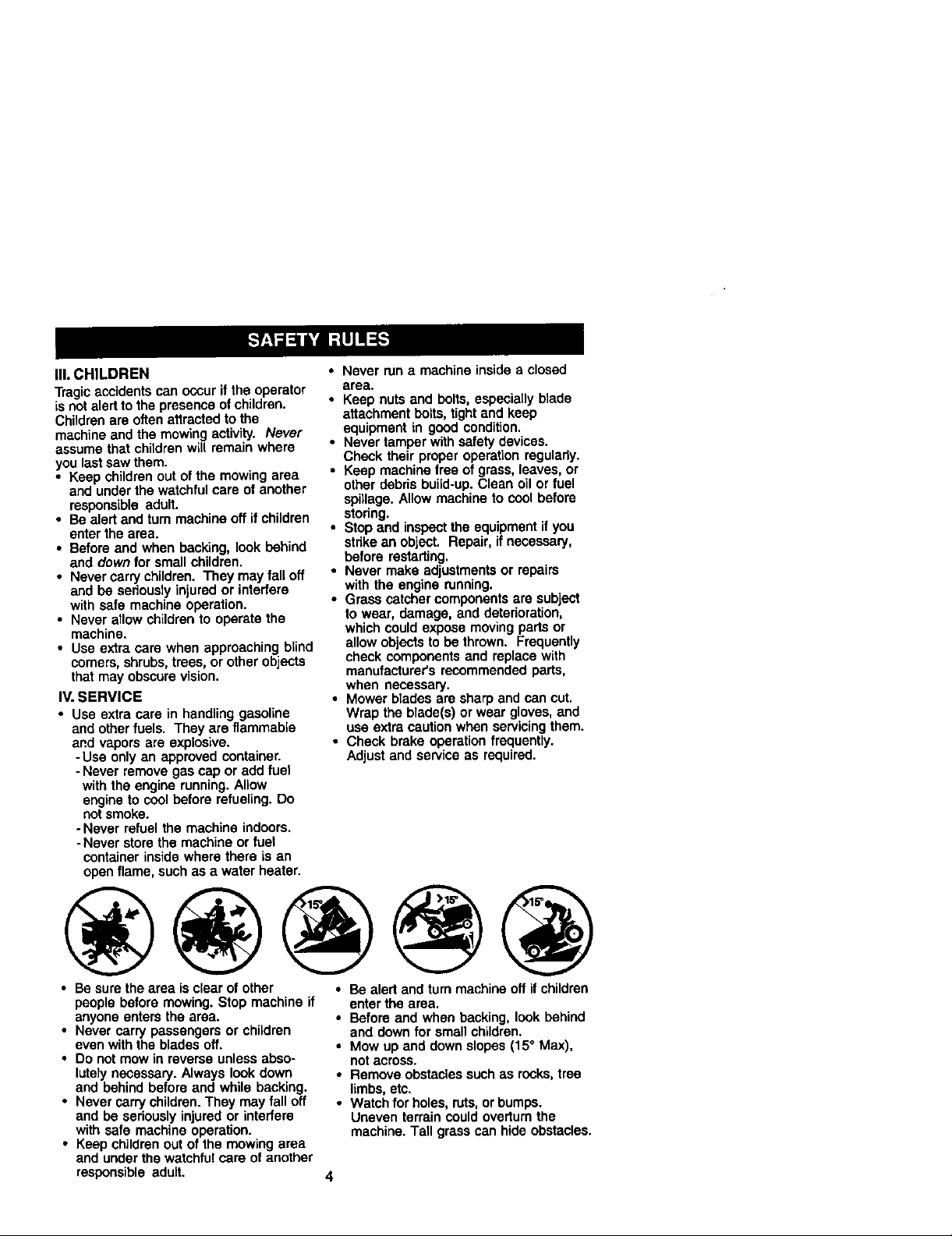
• Be sure the area isclear of other
people before mowing. Stop machine if
anyone enters the area.
• Never carry passengers or children
even with the blades off.
• Do not mow in reverse unless abso-
lutely necessary. Always look down
and behind before and while backing.
• Never carry children. They may fall off
and be seriously injured or interfere
with safe machine operation.
• Keep children out of the mowing area
and under the watchful care of another
responsible adult.
• Be alert and turn machine off if children
enter the area.
• Before and when backing, look behind
and down for small children.
• Mow up and down slopes (15° Max),
notacross.
• Remove obstacles such as rocks, tree
limbs, etc.
• Watch for holes, ruts, or bumps.
Uneven terrain could overturn the
machine. Tall grass can hide obstacles.
4
Page 5
• Use slow speed. Choose a low gear so
that you will not have to stop or shift
while on the slope.
• Avoid starting or stopping on a slope. If
tires lose traction, disengage the
blades and proceed slowly straight
down the stope.
• If machine stops while going uphill,
disengage blades, shift into reverse
and back down slowly.
• Do not turn on slopes untess neces-
sary, and then, turn slowlyand gradu-
ally downhill, if possible.
_,Look for this symbol to point out
important safety precautions. It means
CAUTIONll! BECOME ALERTlt! YOUR
SAFETY IS INVOLVED.
_ CAUTION: In order to prevent
accidental starting when setting up,
transporting, adjusting or making repairs,
always disconnect spark plug wire and
place wire where it cannot contact spark
plug.
,_ CAUTION: Do not coast down a hill
in neutral, you may lose control of the
tractor.
CAUTION: Tow only the attachments
that are recommended by and comply
with specifications of the manufacturer of
your tractor. Use common sense when
towing. Operate only at the lowest
possible speed when on a slope. Too
heavy of a load, while on a slope, is
dangerous. Tires can lose traction with
the ground and cause you to lose control
of your tractor.
_WARNING: Engine exhaust, some of
its constituents, and certain vehicle
components contain or emit chemicals
known to the State of California to cause
cancer and birth defects or other repro-
ductive harm.
_WARNING: Battery posts, terminals
and related aocessodes contain lead and
lead compounds, chemicals known to the
State of California to cause cancer and
birth defects or other reproductive harm.
Wash hands after handling.
Page 6
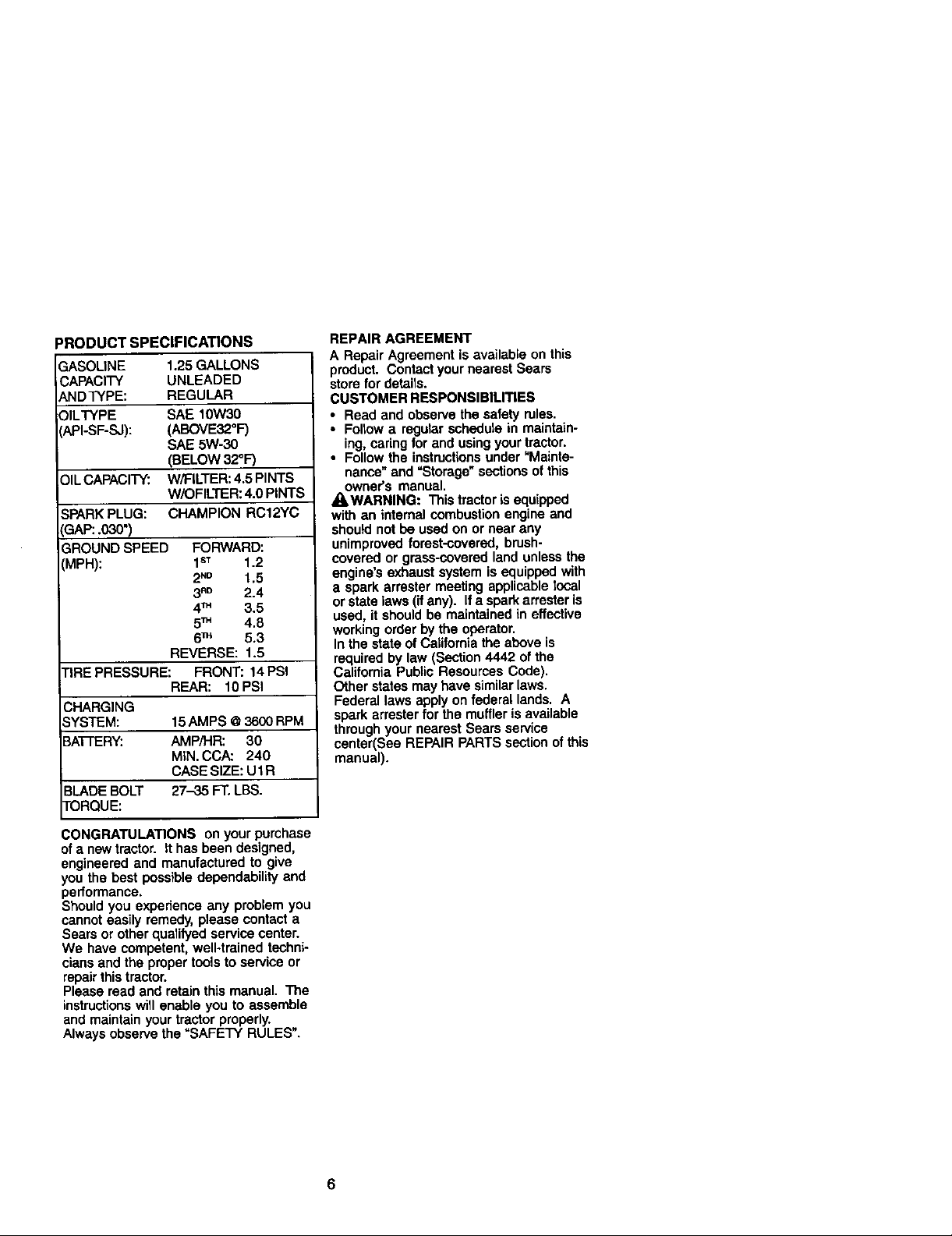
3RODUCT SPECIFICATIONS
GASOLINE 1,25 GALLONS
.3APACITY UNLEADED
\NDTYPE: REGULAR
)ILTYPE SAE 10W30
API-SF-SJ): (ABOVE32 °F)
SAE 5W-30
(BELOW 32°F)
_)ILCAPACITY: W/FILTER: 4.5 PINTS
W/OFILTER: 4.0 PINTS
SPARK PLUG: CHAMPION RC12YC
IGAP:.030")
3ROUND SPEED FORWARD:
'_MPH): 1sT 1.2
2_ 1.5
3RD 2.4
4TM 3.5
5TM 4.8
6TM 5.3
REVERSE: 1.5
TIRE PRESSURE: FRONT: 14 PSi
REAR: 10PSI
CHARGING
SYSTEM: 15AMPS @3600 RPM
BATTERY: AMP/HR: 30
MIN. CCA: 240
CASE SIZE: UlR
BLADEBOLT 27-35 FT. LBS.
TORQUE:
REPAIR AGREEMENT
A Repair Agreement is available on this
product. Contact your nearest Sears
store for details.
CUSTOMER RESPONSIBILITIES
• Read and observe the safety rules,
• Follow a regular schedule in maintain-
ing, caring for and using your tractor.
• Follow the instructionsunder "Mainte-
nance" and =Storage" sections of this
owner's manual.
_WARNING: This tractor is equipped
with an internal combustion engine and
should not be used on or near any
unimproved forest-covered, brush-
covered or grass-covered land unless the
engine's exhaust system is equipped with
a spark arrester meeting applicable local
or state laws (ifany). Ifa spark arrester is
used, it should be maintained in effective
working order by the operator.
In the state of California the above is
required by law (Section 4442 of the
California Public Resources Code).
Other states may have similarlaws.
Federal laws apply on federal lands. A
spark arrester for the muffler is available
through your nearest Sears service
center(See REPAIR PARTS section of this
manual).
CONGRATULATIONS on your purchase
ofa newtractor. It has been designed,
engineered and manufactured to give
you the best possible dependability and
performance.
Should you experience any problem you
cannot easily remedy, please contact a
Sears or other qualifyed service center.
We have competent, well-trained techni-
cians and the proper tools to service or
repair this tractor.
Please read and retain this manual. The
instructions will enable you to assemble
and maintain your tractor properly.
Always observe the "SAFETY RULES".
6
Page 7
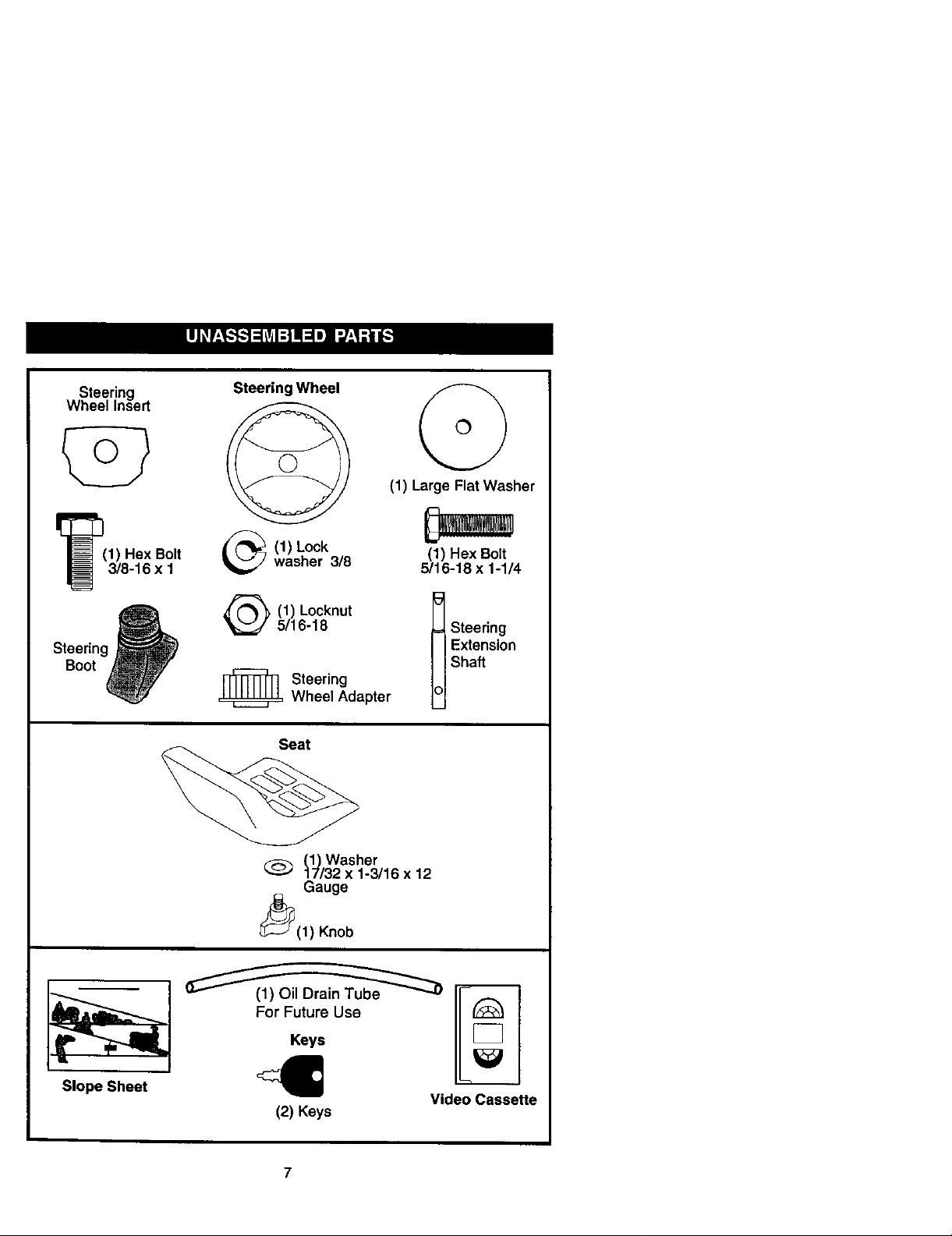
Steering
Wheel Insert
Steering Wheel
(1) Large Flat Washer
Steering
Boot q
1) Hex Bolt
3/8-16 x 1
(1) Lockwasher 3/8
(1) Locknut
5/16-18
_ Steering
Wheel Adapter
Seat
(_Washer
17/32 x 1-3/16 x 12
Gauge
_(1) Knob
(1) Hex Bolt
5/16-18 x 1-1/4
Steering
Extension
Shaft
S,opeSh.e,II:l
(2) Keys
Video Cassette
Page 8
Your new tractor has been assembled at the factory with exception of those parts left
unassembled for shipping purposes. To ensure safe and proper operation of your
tractor aU parts and hardware you assemble must be tightened securely. Use the
correct tools as necessary to insure proper tightness. Review the video cassette before
you begin.
TOOLS REQUIRED FOR ASSEMBLY
A socket wrench set will make assembly
easier. Standard wrench sizes you need
are listed below.
(1) 9/16"wrench (1) Pliers
(2) 1/2"wranch (1) Utility knife
(1) Tire pressure gauge
When right or left hand is mentioned in
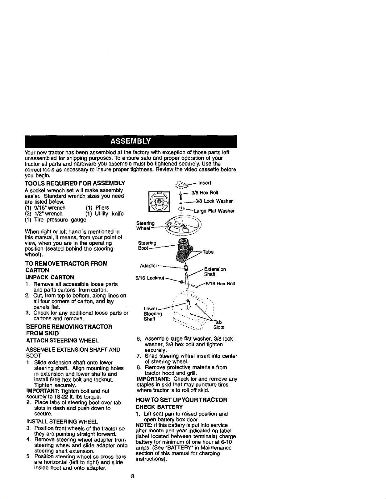
'_ .---- 3/S HexBolt
Steering
Wheel
_.:_._./Insert
_T..._3/8 LockWasher
_"_-Larga Rat Washer
this manual, it means, from your point of
view, when you are in the operating
Steenng _._
position (seated behind the steering
wheel).
TO REMOVETRACTOR FROM
CARTON
UNPACK CARTON
1. Remove all accessible loose parts
Boot-------"--- _
Adapter--------___
5/16 Locknut _,,...._
Tabs
Extension
/ Shaft
_._5/16 Hex Bolt
and parts cartons from carton.
2. Cut, from top to bottom, along lines on
all four corners of carton, and lay
panels flat.
3. Check for any additional loose parts or
cartons and remove.
BEFORE REMOVINGTRACTOR
FROM SKID
ATrACH STEERINGWHEEL
ASSEMBLE EXTENSION SHAFT AND
BOOT
1. Slide extension shaft onto lower
steering shaft. Align mounting holes
in extension and lower shafts and
install 5/16 hex bolt and lecknut.
Tighten securely.
IMPORTANT: Tighten bolt and nut
securelyto 18-22 ft. Ibs torque.
2. Place tabs of steering boot over tab
slots in dash and push down to
secure.
INSTALL STEERING WHEEL
3. Position front wheels of the tractor so
they are pointing straight forward.
4. Remove steering wheel adapter from
steering wheel and slide adapter onto
steedng shaft extension.
5. Position steering wheel so cross bars
are horizontal (left to right) and slide
inside boot and onto adapter.
6. Assemble large flat washer, 3/8 lock
washer, 3/8 hex bolt and tighten
securely.
7. Snap steering wheel insert into center
of steering wheel.
8. Remove protective materials from
tractor hood and grill.
IMPORTANT: Check for and remove any
staples in skid that may puncture tires
where tractor is to roll off skid.
HOWTO SET UPYOURTRACTOR
CHECK BA'rrERY
1. Lift seat pan to raised position and
open battery box door.
NOTE: If this battery isput into service
after month and year indicated on label
(label located between terminals) charge
battery for minimum of one hourat 6-10
amps. (See "BATrERY" in Maintenance
section of this manual for charging
instructions).
8
Page 9
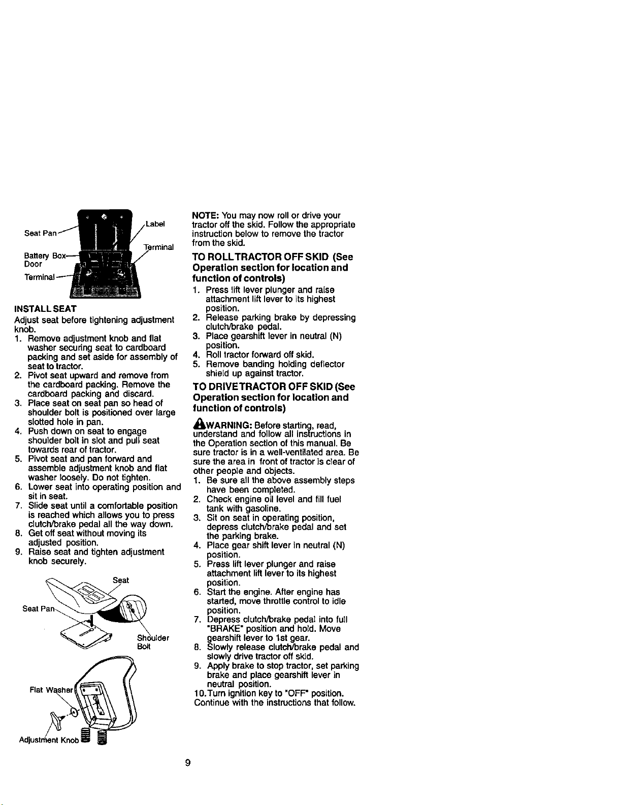
Terminal
Batteej
Door
INSTALL SEAT
Adjust seat before tightening adjustment
knob.
1. Remove adjustment knob and flat
washer securingseat to cardboard
pecking and set aside for assembly of
seat to tractor.
2. Pivot seat upward and remove from
the cardboard packing. Remove the
cardboard packing and discard.
3. Place seat on seat pan so head of
shoulder bolt is positioned over large
slotted hole in pan.
4. Push down on seat to engage
shoulder bolt in slot and pull seat
towards rear of tractor.
5. Pivot seat and pan forward and
assemble adjustment knob and fiat
washer loosely. Do nottighten.
6. Lower seat into operating position and
sit inseat.
7, Slide seat until a comfortable position
is reached which allows you to press
clutch/brake pedal all the way down.
8. Get off seat without moving its
adjusted position.
9. Raise seat and tighten adjustment
knob securely.
Seat
Bolt
Rat W_er_
NOTE: You may now rollor drive your
tractor oft the skid. Follow the appropriate
instructionbelow to remove the tractor
from the skid.
TO ROLLTRACTOR OFF SKID (See
Operation section for location and
function of controls)
1. Press lift lever plunger and raise
attachment liftlever to its highest
position,
2. Release parking brake by depressing
clutch/brake pedal.
3. Place gearshift lever in neutral (N)
position.
4. Roll tractorforward oft skid.
5. Remove banding holding deflector
shield up against tractor.
TO DRIVETRACTOR OFF SKID (See
Operation section for location and
function of controls)
,_kWARNING: Before starting, read,
understand and follow all ins|ructions in
the Operation section ofthis manual. Be
sure tractor is in a well-ventilated area. Be
sure the area in front of tractor]s clear of
other people and objects.
1. Be sure all the above assembly steps
have been completed.
2. Check engine oil level and fill fuel
tank with gasoline.
3. Sit on seat in operating position,
depress clutch/brake pedal and set
the parking brake.
4. Place gear shift lever in neutral (N)
position.
5. Press liftlever plunger and raise
attachment lift lever to its highest
position.
6. Start the engine. After engine has
started, move throttle control to idle
position.
7. Depress clutch/brake pedal into full
"BRAKE" position and hold. Move
gearshift lever to 1st gear.
8. Slowly release clutch/brake pedal and
slowlydrive tractor off skid.
9. Apply brake to stop tractor, set parking
brake and place geamhift lever in
neutral position.
10.Turn ignitionkey to "OFF" position.
Continue with the instructionsthat follow.
Page 10

INSTALLMULCHERPLATE
(Ifpreviouslyremoved)
1. Raiseandholddeflectorshieldin
uprightposition.
2. Placefrontofmulcharplateoverfront
ofmowerdeckopeningandslideinto
place,asshown,
3, Hookfrontlatchintoholeonfrontof
mowerdeck.
4, Hookrearlatchintoholeonbackof
mowerdeck.
ACAUTION: Do not remove deflector
shield from mower. Raise and hold shield
when attaching mulcher plate and allow it
to rest on plate while in operation.
Muldher
Deflector_ Plate
Shield
Latch
Hooks
TO CONVERTTO BAGGING OR
DISCHARGING
Simply remove mulcher plate and store in
a safe piece. Your mower is now ready for
discharging or installation of optional
grass catcher accessory.
NOTE: It is not necessary tochange
blades. The mulcher blades are de-
signed for discharging and bagging also,
CHECKTIRE PRESSURE
The tires on your tractor were overlnflated
at the factory for shipping purposes.
Correcttire pressure is important for best
cutting performance.
• Reduce tire pressure to PSI shown in
"PRODUCT SPECIFICATIONS" section
of this manual.
CHECK DECK LEVELNESS
For best cutting results, mower housing
should be properly leveled. Sea "TO
LEVEL MOWER HOUSING" in the
Service and Adjustments section of this
manual.
CHECK FOR PROPER POSITION OF
ALL B ELTS
See the figures that are shown for
replacing motion and mower blade drive
belts in the Service and Adjustments
sectionof this manual. Verify that the
belts are routed correctly.
CHECK BRAKE SYSTEM
After you learn how to operate your
tractor,check to see that the brakeis
properly adjusted. See "TO ADJUST
BRAKE" in the Service and Adjustments
section of this manual.
•#CHECKLIST
BEFORE YOU OPERATE AND ENJOY
YOUR NEW TRACTOR, WE WISH TO
ASSURE THAT YOU RECEIVE THE BEST
PERFORMANCE AND SATISFACTION
FROM THIS QUALITY PRODUCT.
PLEASE REVlEWTHE FOLLOWING
CHECKLIST:
/ All assembly instructions have been
completed.
,/NO remaining loose parts in carton.
,/Battery is properly prepared and
charged. (Minimum 1 hour at 6 amps).
/ Seat is adjusted comfortably and
tightened securely.
,/All tires are properly inflated. (For
shipping purposes, the tires were
overinflated at the factory).
,/Be sure mower deck is properly leveled
side-to-side/front-to-rear for best cutting
results. (Tires must be properly inflated
for leveling).
,/Check mower and drive belts. Be sure
they are routed properly around pulleys
and inside all belt keepers.
,/Check wiring. Sea that all connections
are still secure and wires are properly
clamped.
WHILE LEARNING HOW TO USE YOUR
TRACTOR, PAYEXTRA A'I-I'ENTION TO
THE FOLLOWING IMPORTANT ITEMS:
,/Engine oil is at proper level.
,/Fuel tank is filled with fresh, clean,
regular unleaded gasoline.
,/Become familiar with all controls - their
location and function. Operate them
before you start the engine.
/ Be sure brake system is in safe
operating condition.
10
Page 11
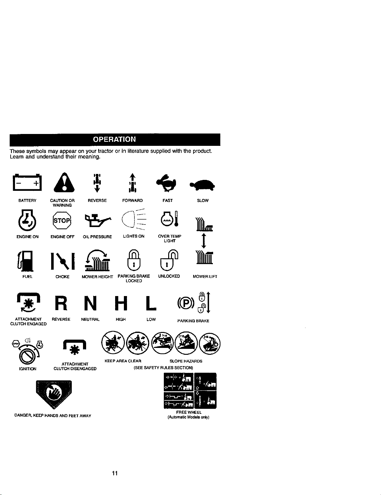
These symbols may appear on yourtractor or in literature suppled with the product.
Learn and understand their meaning.
BATrERY CAUTION OR REVERSE FORWARD FAST SLOW
WARNING
EHO,NEOHENG,HEOFFOILPeESSUnEL,ONTSO.OVI,_MP ]_
FUEL CHOKE MOWER HEIGHT PARKINGBRAKE UNLOCKED
LOCKED
H L
ATTACHMENT REVERSE NEUTRAL HIGH LOW
CLUTCH ENGAGED
IGNITION CLUTCH DISENGAGED (SEE SAFETY RULES SECTION)
ATFACHMENT KEEP AREA CLEAR SLOPE HAZARDS
PARKING BRAKE
MOWERLI_
DANGER. KEEP HANDS AND FEET AWAY
FREE WHEEL
(Automatic Models only)
11
Page 12
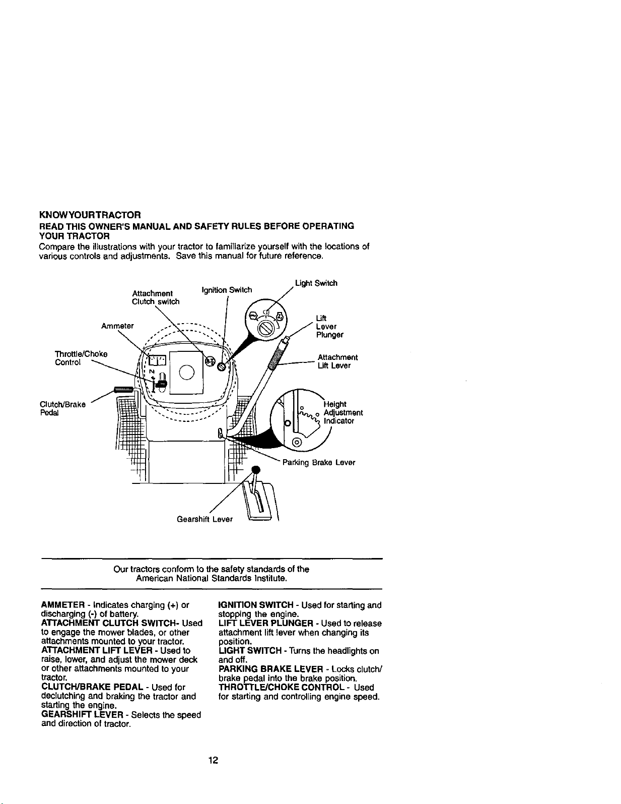
KNOWYOURTRACTOR
READ THIS OWNER'S MANUAL AND SAFETY RULES BEFORE OPERATING
YOUR TRACTOR
Compare the illustrationswith your tractor to familiarize yourself with the locations of
various controlsand adjustments. Save this manual for future reference,
Throttle/Choke
Contml
Clutch/Brake
Psdai
Attachment Ignition Switch
Clutch switch
Ammeter ..... -.
Gearshift Lever
Our tractorsconform to the safety standards of the
American National Standards Institute.
Ught Switch
U_
Lever
Plunger
Attachment
LiR Lever
Height
Adjustment
, Indicator
Parking Brake Lever
AMMETER - Indicates charging (+) or
discharging (-) of battery.
A'FFACHMENT CLUTCH SWITCH- Used
to engage the mower blades, or other
attachments mounted toyour tractor.
A'I'FACHMENT LIFT LEVER - Used to
raise, lower, and adjust the mower deck
or other attachments mounted to your
tractor.
CLUTCH/BRAKE PEDAL - Used for
declutching and braking the tractor and
starting the engine.
GEARSHIFT LEVER - Selects the speed
and direction of tractor.
IGNITION SWITCH - Used for startingand
stopping the engine.
LIFT LEVER PLUNGER - Used to release
attachment lift lever when changing its
position.
LIGHT SWITCH - Turnsthe headlightson
and off.
PARKING BRAKE LEVER - Locks clutch/
brake pedal into the brake position.
THROTTLF_JCHOKE CONTROL- Used
for starting and controllingengine speed.
12
Page 13
The operation of any tractor can result in foreign objects thrown into the
eyes, which can result in severe eye damage. Always wear safety
glasses or eye shields while operating your tractor or performing any
adjustments or repairs. We recommend a wide vision safety mask over
spectacles or standard safety glasses.
HOWTO USEYOURTRACTOR
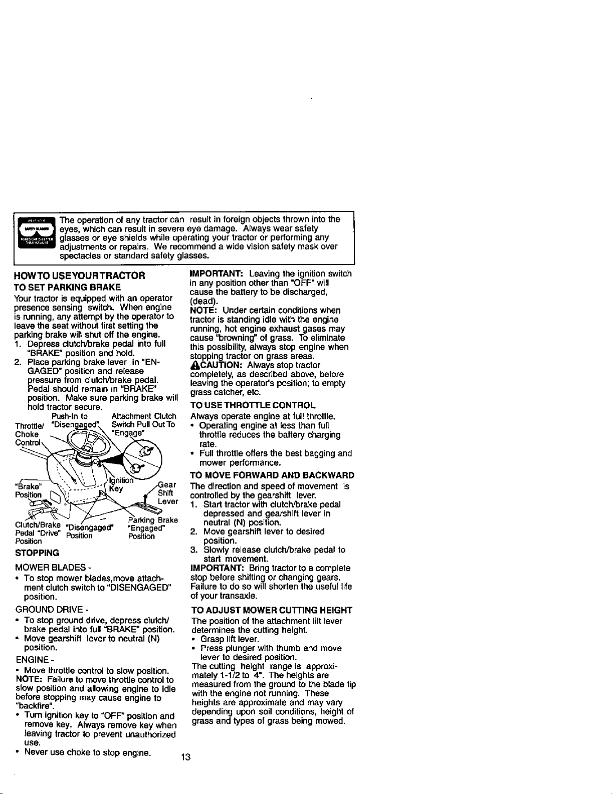
TO SET PARKING BRAKE
Yourtractor is equipped with an operator
presence sensing switch. When engine
is running,any attempt by the operator to
leave the seat without first setting the
parking brake will shut off the engine.
1. Depress clutch/brake pedal into full
"BRAKE" position and hold.
2. Place parking brake lever in "EN-
GAGED" position and release
pressure from clutch/brake pedal.
Pedal should remain in "BRAKE"
position. Make sure parking brake will
hold tractor secure.
Push-Into AttachmentClutch
Throttle/ SwitchPullOutTo
Choke
"Brake"
Position
Clutch/Brake .Engaged _
Pedal =Drive" Position Position
Posif_on
STOPPING
Lever
g Brake
MOWER BLADES -
• To stop mower blades,move attach-
ment clutchswitchto "DISENGAGED"
position.
GROUND DRIVE -
• To stop ground drive, depress clutch/
brake pedal into full =BRAKE" position.
• Move gearshift lever to neutral (N)
position.
ENGINE -
• Move throttle control to slow position.
NOTE: Failure to move throttle controlto
slow position and allowing engine to idle
before stopping may cause engine to
"backfire".
• Turn ignitionkey to "OFF" position and
remove key. Always remove key when
leaving tractor to prevent unauthorized
use,
• Never use choke to stop engine.
IMPORTANT: Leavingthe ignitionswitch
in any position other than "OFF" will
cause the battery to be discharged,
(dead).
NOTE: Under certain conditionswhen
tractor is standing idle with the engine
running, hot engine exhaust gases may
cause =browning" of grass. To eliminate
this possibility,always stop engine when
stopping tractor on grass areas.
_I_CAUTION: Always stoptractor
completely, as described above, before
leaving the operator's position;to empty
grass catcher, etc.
TO USE THROTrLE CONTROL
Always operate engine at full throttle.
• Operating engine at less than full
throftle reduces the battery charging
rate.
• Full throttle offers the best bagging and
mower performance.
TO MOVE FORWARD AND BACKWARD
The direction and speed of movement is
controlled bythe gearshift lever.
1. Start tractor with clutch/brake pedal
depressed and gearshift lever in
neutral (N) position.
2. Move gearshift lever to desired
position.
3. Slowly release clutch/brake pedal to
start movement.
IMPORTANT: Bring tractorto a complete
stop before shifting or changing gears.
Failure to do so will shortenthe useful life
ofyour transaxle.
TO ADJUST MOWER currlNG HEIGHT
The position of the attachment lift lever
determines the cutting height.
• Grasp liftlever.
• Press plunger with thumb and move
lever to desired position.
The cutting height range is approxi-
mately 1-1/2 to 4". The heightsare
measured from the ground to the blade tip
with the engine not running. These
heights are approximate and may vary
depending upon soil conditions, height of
grass and types of grass being mowed.
13
Page 14
• The average lawn should be cut to
approximately 2-1/2 inches during the
cool season and to over 3 inches
during hot months. For healthier and
better looking lawns, mow often and
after moderate growth.
• For best cutting performance, grass
over 6 inches in height should be
mowed twice. Make the first cut
relativelyhigh; the second to desired
height.
TO ADJUST GAUGE WHEELS
Gauge wheels are properly adjusted
when they are slightly off the ground
when mower is at the desired cutting
height in operating position.Gauge
wheels then keep the deck in proper
position to help prevent scalping in most
terrain conditions.
NOTE: Adjust gauge wheels with tractor
on a flat level surface.
1. Adjust mower to desired cutting height
(See "TO ADJUST MOWER CU'I-rlNG
HEIGHT" in the Operation section of
this manual).
2. With mower in desired height of cut
position, gauge wheels should be
assembled so they are slightly off the
ground. Install gauge wheel in
appropriate hole with shoulder bolt. 3/
8 washer, and 3/8-16 Iooknutand
tighten securely.
3. Repeat for opposite side installing
gauge wheel in same adjustment
hole.
Gauge .\ r_ \
Wheel _-_ _ _,_
Bracket_',_ i !_"_F--_
_ _J Shoulder
3/8 Washer._ _,_/'Bolt
GaugeWheel
TO OPERATE MOWER
Your tractor is equipped with an operator
presence sensing switch. Any attempt by
the operator to leave the seat with the
engine running and the attachment clutch
engaged will shut off the engine.
1. Select desired height of cut.
2. Start mower blades by engaging
attachment clutch control
TO STOP MOWER BLADES -
disengage attachment clutch control.
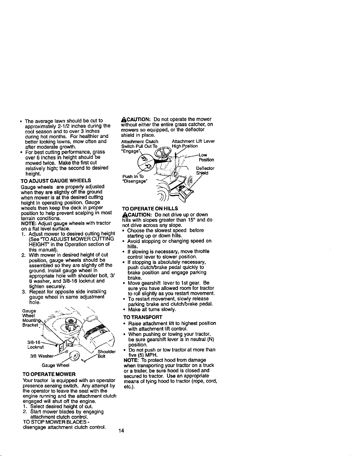
_CAUTION: Do not operate the mower
withouteither the entire grasscatcher, on
mowers so equipped, or the deflector
shield in place.
AttachmentClutch AttachmentUft Lever
SwitchPullOutTo _ HighPosition
Engage., _._ .-S<_..._Lp_Wtion
_'_, Deflector
ueh,n%
Disengage" _
TO OPERATE ON HILLS
_I,CAUTION: Do not drive up or down
hills with slopes greater than 15° and do
not drive across any slope.
• Choose the slowest speed before
starting up or down hills.
• Avoid stopping or changing speed on
hills.
• If slowing is necessary, move throttle
control lever to slower position.
• If stopping is absolutely necessary,
push clutch/brake pedal quickly to
brake position and engage parking
brake.
• Move gearshift lever to 1st gear. Be
sure you have allowed room for tractor
to rollslightlyas you restart movement.
• To restart movement, slowly release
parking brake and clutch/brake pedal
• Make all turns slowly.
TO TRANSPORT
• Raise attachment lift to highest position
with attachment lift control.
• When pushingor towing your tractor,
be sure gearshift lever is in neutral (N)
position.
• Do not push ortow tractor at more than
five (5) MPH.
NOTE: To protect hoodfrom damage
when transportingyour tractor on a truck
or a trailer, be sure hood is closed and
secured to tractor. Use an appropriate
means of tying hoodto tractor (rope, cord,
etc.),
14
Page 15
TOWING CARTS AND OTHER
ATTACHMENTS
Tow only the attachments that are
recommended by and comply with
specificationsof the manufacturer of your
tractor.Use common sense when towing.
Tooheavy of a load, while on a slope, is
dangerous.Tires can lose traction with
"theground and cause you to lose controt
ofyour tractor.
BEFORE STARTING THE ENGINE
CHECK ENGINE OIL LEVEL
The engine in your tractor has been
shipped, from the factory, already filled
with summer weightoil.
1. Check engine oil with tractor on level
ground.
2. Unthread and remove oil fill cap/
dipstick;wipe oil off. Reinsert the
dipstick into the tube and rest oil fill
cap on the tube. Do notthread the
cap ontothe tube. Remove and read
oil level. If necessary, add oil until
"FULL" mark on dipstickis reached.
Do not overfill.
• For coldweather operationyou should
change oil for easier starting(See =OIL
VISCOSITY CHART" inthe Mainte-
nance section ofthis manual).
• To change engine oil, see the Mainte-
nance sectionin this manual
ADD GASOLINE
• Fill fuel tank. Use fresh, clean, regular
unleaded gasoline with a minimum of
87 octane. (Use of leaded gasoline
will increase carbon and lead oxide
deposits and reduce valve life). Do not
mix oil with gasoline. Purchase fuel in
quantitiesthat can be used within 30
days to assure fuel freshness.
IMPORTANT: When operating in
temperatures below 32°F(0°C), use fresh,
clean winter grade gasoline to help
insure good cold weather starting.
_kWARNING: Experience indicates that
alcohol blended fuels (called gasohol or
using ethanol or methanol) can attract
moisture which leads to separation and
formation of acids during storage. Acidic
gas can damage the fuel system of an
engine while in storage. To avoid engine
problems, the fuel system should be
emptied before storage of 30 days or
longer. Drain the gas tank, start the
engine and let it run untilthe fuel lines
and carburetor are empty. Use fresh fuel
next season. See Storage Instructionsfor
additional information. Never use engine
or carburetor cleaner products in the fuel
tank or permanent damage may occur.
[I, CAUTION: Fill to bottomof gas tank
fillerneck. Do notoverfill. Wipe off any
spilled oil or fuel. Do not store, spill or
use gasoline near an open flame.
TO START ENGINE
When starting_e enginefor thefirsttlme or if
the enginehas runoutof fuel,itwilltakeextra
crankingtimeto rnovefuelfromthe tankto
engine.
1. Sit on seat in operating position,
depress clutcWbrake pedal and set
parking brake.
2. Place gear shift lever in neutral (N)
position.
3. Move attachment clutch to =DISEN-
GAGED" position.
4. Move throttle control to choke position.
NOTE: Beforestarting,reedthewarmand
cold startingproceduresbelow.
5. Insert key into ignition and turn key
clockwise to "START" positionand
release key as soon as engine starts.
Do not run starter continuouslyfor
more than fifteen seconds per minute.
Ifthe engine does not start after
several attempts, move throttle control
to fast position, wait a few minutesand
try again. If engine stilldoes not start,
move the throttlecontrol back to the
choke position and retry.
WARM WEATHER STARTING(50° F and
_oove)
6. When engine starts, move the throttle
control to the fast position.
• The attachments and ground drive can
now be used. If the engine does not
accept the load, restart the engine end
allow it to warm up for one minute
using the choke as described above.
15
Page 16
COLD WEATHER STARTING ( 50=F and
below)
6. When engine starts, allow engine to
run with the throttle control in the
choke position until the engine runs
roughly, then move throttle control to
fast position. This may require an
engine warm-up period from several
seconds to several minutes, depend-
ing on the temperature.
• The attachments can also be used
during the engine warm-up pedod.
NOTE: if at a I'_h _ (above 3000 feet)
or incoldtemperatures(below32 F) the
carburetorfuel mixturemay need to be
adjustedfor bestengineperformance. See
"TOADJUST CARBURETOR" inthe Service
andAdjustmentssectiono_thismanual.
MOWING TIPS
• Mower should be properly leveled for
best mowing performance. See "TO
LEVEL MOWER HOUSING" in the
Service and Adjustments section of this
manual.
• The left hand side of mower should be
used for trimming.
• Drive so that clippings are discharged
onto the area that has been cut. Have
the cutarea to the right of the tractor.
This will resultin a more even distribu*
tion of clippings and more uniform
cutting.
• When mowing largo areas, start by
turningto the rightso that clippings will
discharge away from shrubs, fences,
ddveways, etc. After one ortwo
rounds, mow in the opposite direction
making left hand turns until finished.
• If grass is extremely tall, it should be
mowed twice to reduce load and
possible fire hazard from dded clip-
pings. Make first cut relatively high;the
second to the desired height.
• Do not mow grass when it is wet. Wet
grass will plug mower end leave
undesirable clumps. Anow grass to dry
before mowing.
• Always operate engine at full throttle
when mowing to assure better mowing
performance and proper discharge of
material. Regulate ground speed by
selecting a low enough gear to give the
mower cuttingperformance as well as
the quality of cut desired.
• When operating attachments, select a
ground speed that will suitthe terrain
and give best performance of the
attachment being used.
I
MULCHING MOWINGTIPS
IMPORTANT: For best performance,
keep mower housing free of built-up
grass and trash. Clean after each use.
• The special mulching blade will recut
the grass clippings many times and
reduce them in size so that as they fall
onto the lawn they will disperse into the
grass and not be noticed. Also, the
mulched grass will biodegrade quickly
to provide nutrients for the lawn.
Always mulch with your highest engine
(blade) speed as this will provide the
best recutting action of the blades.
• Avoid cutting your lawn when it is wet.
Wet grass tends to form clumps and
interferes with the mulching action.
The best time to mow your lawn is the
eady afternoon. At this time the grass
has dried and the newly cut area will
not be exposed to the direct sun.
• For best results, adjust the mower
cutting height so that the mower cuts off
only the top one-third of the grass
blades. For extremely heavy mulching,
reduce your width of cut on each pass
and mow slowly.
• Certain types of grass and grass
conditions may require that an area be
mulched a second time to completely
hide the clippings. When doing a
second cut, mow across or perpendicu-
lar to the first cut path.
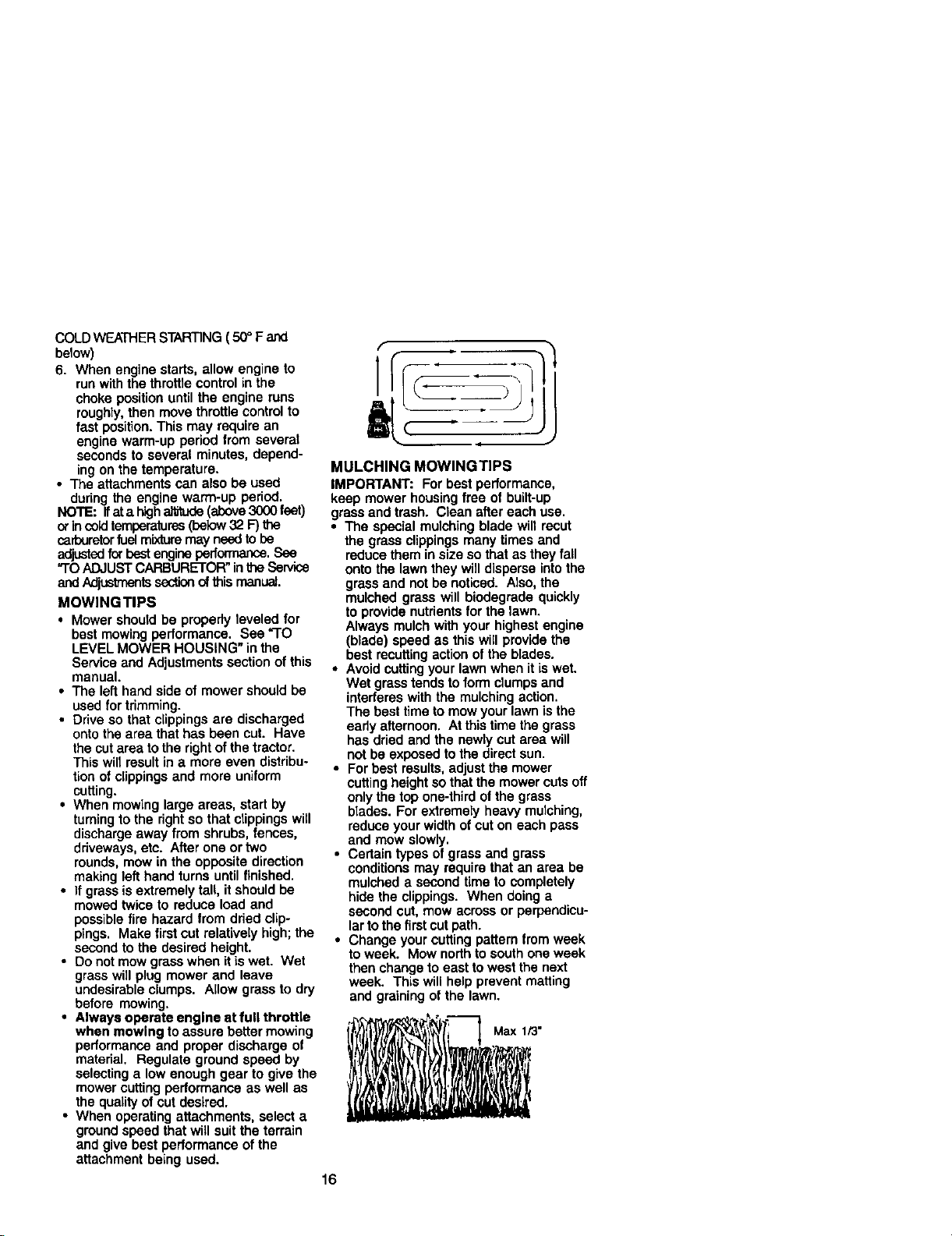
• Change your cutting pattern from week
to week. Mow north to south one week
then change to east to west the next
week. This will help prevent matting
and graining of the lawn.
Max 1/3"
16
Page 17
AS YOU COMPLETE
Ch_d_BrakeOr_a,on t/ t/
CheW'arePm_ure I,/ t/
C_ed_OperatorPresenceand
T Interlock Syste¢_ I_
R CheckforLooseFast_ _ 1/7 I_
Sharpe_R_ace Mowor818de_ V'4
T Lub_,=.=,C.=_ t/ l/
0 CheexBat__
R c_,__ =ridTm_t= Vt V'
Che_ Transaxle Cooling
A_lu_8lade _$) T_ I,/s
A_u_ MotionOdwBen(s)T_ iV/s
Ch=_E,_,oO,=.=v_ V' t/
E Cleln Nr F'llter ql_=!
N CleanAirScreen f/'=
bM_pectMulfledSpark Armster 11_
Rep_caCaR_ (wtqutppeo_ V_.=
Re_a=asparkP_ug V' V"
Replace N_ Rlte_ Paper C8_tddge V*e
Replace Fue_ Filter
1 - CI_I_ m0nl OP_mv/_n o0emaing uetde¢i hlevy 10ed0¢ kl hl_t lld01_t ka_oemb=_ 5. N _ _1_ _¢lultab_ ily_em.
2 - _c= rr_= caemvw_mop_mtk_ m_ or 4usly ¢_-_=&o_ e. Not mqui_d if eq_p_d w_ m_ime,tee_e4me _wy.
3 - If eq_pped wi_ ol h. ci_nge el _e.y 50 hou_ 7. T_4e_ front =[de pk_ boll _o35 L._4. r_tdmu_
4 - Rep:o_ btede= rnom clteq _lm m0._tg i_ i_*_*/axe. Oo rxx o.e,t;ghlen.
GENERAL RECOMMENDATIONS
The warranty on this tractor does not
cover items that have been subjected to
LUBRICATION CHART
Zerk Zerk
operatorabuse or negligence. To receive
full value from the warranty, operator must
maintain tractor as instructed in this
manual.
Some adjustments will need to be made
(_)FrontWheel
Bearing
Zerk
periodically to propedy maintain your
tractor.
All adjustments in the Service and
Adjustments section of this manual
should be checked at least once each
season.
• Once a year you should replace the
spark plug, clean or replace air filter,
and check blades and belts for wear. A
new spark plug and clean air filter
assure proper air-fuel mixture and help
your engine run better and last longer.
BEFORE EACH USE
1. Check engine oil level.
2. Check brake operation.
3. Check tire pressure.
4. Check operator presence and
interlocksystems for proper operation.
5. Check forloose fasteners.
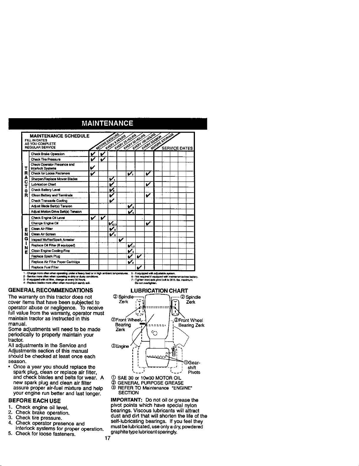
_) SAE 30 or 10w30MOTOROIL
_) GENERAL PURPOSEGREASE
_) REFERTO Maintenance "ENGINE"
IMPORTANT: Do not oil or grease the
pivot points which have special nylon
bearings. Viscous lubricantswill attract
dust and dirt that will shorten the life of the
self-lubdcating bearings. Ifyou feel they
mustbelubricated,useonlya dry,powdered
graphitetypelubricantsparingly.
17
'= _-- ,--' shift
L__._ L_÷J Pivots
SECTION
Beanng Ze_
Page 18
TRACTOR
Always observe safety rules when
performing any maintenance.
BRAKE OPERATION
If tractor requires more than six (6) feet
stoppingdistance at high speed in
highest gear, then brake must be ad-
justed. (See =TOADJUST BRAKE" in the
Service and Adjustments section of this
manual).
TIRES
• Maintain proper air pressure in all tires
(See "PRODUCT SPECIFICATIONS"
section of this manual).
• Keep tiros free of gasoline, oil, or insect
control chemicals which can harm
rubber.
• Avoid stumps, stones, deep ruts, sharp
objectsand other hazards that may
cause tire damage.
NOTE: To seal tirepunctures and prevent
flat tirosdue to slow leaks, tire sealant
may be purchased from your local parts
dealer. Tire sealant also prevents tire dry
rot and corrosion.
OPERATOR PRESENCE SYSTEM
Be sure operator presence and interlock
systems are workingproperly. If your
tractor does notfunction as described,
repair the problem immediately.
• The engine should not start unless the
brake pedal is fully depressed and
attachment clutchcontrol is in the
disengaged position.
• When the engine is running, any
attempt by the operator to leave the
seat without first setting the parking
brake should shut off the engine.
• When the engine is running and the
attachment clutch is engaged, any
attempt by the operator to leave the
seat should shut off the engine.
• The attachment clutch should never
operate unless the operator is in the
seat.
BLADE CARE
For best results mower blades must be
kept sharp. Replace bent or damaged
blades.
BLADE REMOVAL
1. Raise mower to highest position to
allow access to blades.
2, Remove hex bolt, lock washer and flat
washer securing blade.
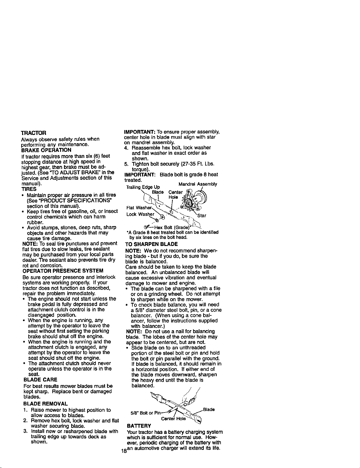
3. Install new or resharpened blade with
trailing edge up towards deck as
shown.
IMPORTANT: To ensure proper assembly,
center hole in blade must align with star
on mandrel assembly.
4. Reassemble hex belt, lock washer
and flat washer in exact order as
shown.
5. Tighten bolt securely (27-35 Ft. Lbs.
torque).
IMPORTANT: Blade bolt is grade 8 heat
treated.
TrailingEdgeUp /
Blade Center j_
MandrelAssembly
Fat
,o k
_---Hex Bolt (Grade)*'*'*'*'*'*'*'*'*'_"__
*A Grade8 heattreatedboltcanbe identified
by sixlinesonthe bolthead.
TO SHARPEN BLADE
NOTE: We do not recommend sharpen-
ing blade - but if you do, be sure the
blade is balanced.
Care should be taken to keep the blade
balanced. An unbalanced blade will
cause excessive vibration and eventual
damage to mower and engine.
• The blade can be sharpened with a file
or on a grinding wheel. Do not attempt
to sharpen while on the mower.
• To check blade balance, you will need
a 5/8" diameter steel bolt, pin, or a cone
baiancer. (When using a cone bal-
ancer, follow the instructions supplied
with balancer.)
NOTE: Do not use a nail for balancing
blade. The lobes of the center hole may
appear to be centered, but are not.
• Slide blade on to an unthreaded
portion of the steel bolt or pin and hold
the bolt or pin parallel with the ground.
If blade is balanced, it should remain in
a horizontal position. If either end of
the blade moves downward, sharpen
the heavy end untitthe blade is
balanced.
"_ _ Blade
BA'I'I'ERY
Yourtractor hasa battery charging system
which issufficient for normal use. How-
ever, periodic charging of the battery with
18an automotive charger will extend its life.
Page 19

• Keep battery and terminals clean.
, Keep battery bolts tight.
, Keep small vent holes open.
, Recharge at 6-10 amperes for 1 hour.
NOTE: The original equipment battery on
/our tractor is maintenance free, Do not
attempt to open or remove caps or covers.
_dding or checking level of electrolyte is
not necessary.
TO CLEAN BA'I-FERY AND TERMINALS
Corrosion and dirt on the battery and
terminals can cause the battery to "leak"
power.
1. Open battery box door.
2. Disconnect BLACK battery cable first
then RED battery cable and remove
batteryfrom tractor.
3. Rinse the battery with plainwater and
dry.
4. Clean terminals and battery cable
ends with wire brush untilbright.
5. Coat terminals with grease or petro-
leum jelly.
6. Reinstall battery (See "REPLACING
BATTERY" inthe SERVICE AND
ADJUSTMENTS section of this
manual).
V-BELTS
Check V-belts for deterioration and wear
after 100 hours of operation and replace if
necessary. The belts are not adjustable.
Replace belts if they begin to slip from
wear.
TRANSAXLE COOLING
Keep transaxle free from build-up of dirt
and chaff which can restrictcooling.
ENGINE
LUBRICATION
Only use highquality detergent oil rated
NithAPI service classificationSF-SJ.
Selectthe oil's SAE viscosity grade
according to your expected operating
:emperature.
• .m o _ m _ m im iw
Change the oil after every 50 hours of
operationor at least once a year if the
tractor is notused for 50 hours in one
year.
Check the crankcase oil level before
starting the engine and after each eight
(8) hoursof operation. Tighten oil fill cap/
dipsticksecurely each time you check the
oil level.
TO CHANGE ENGINE OIL
Determine temperature range expected
before oil change. All oil must meet API
service classificationSF-SJ.
• Be sure tractor ison level surface.
• Oil will drain more freely when warm.
• Catch oil in a suitable container.
1. Remove oil fill cap/dipstick. Be careful
notto allow did to enter the engine
when changing oil.
2. Remove cap from end of drain valve
and install the drain tube onto the
fitting.
3. Unlock drain valve by pushing inward
slightly and turning counterclcokwise.
4. To open, pug out on the drain valve.
5. After oil has drained completely, close
and lock the drain valve by pushing
inward and turning clockwise until the
pin is in the locked positionas shown.
6. Remove the drain tube and replace
the cap onto to the end of the drain
valve.
7. Refill engine with oil through oil fill
dipstick tube. Pour slowly. Do not
overfill. For approximate capacity see
"PRODUCT SPECIFICATIONS"
section of this manual
8. Use gauge on oil fill cap/dipstick for
checking level. Insert dipstick into the
tube and restthe oilfill cap on the
tube. Do notthread the cap ontothe
tube when taking reading. Keep oil
at "FULL" line on dipstick. Tighten cap
onto the tube securely when finished.
OilDrainValve
Closed
and
Locked (
Posit_on ::;.]..
c
CLEAN AIR SCREEN
Air screen must be kept free of dirt and
chaff to prevent engine damage from
overheating. Clean with a wire brush or
compressed air to remove dirt and
stubborn dried gum fibers.
CLEAN AIR INTAKE/COOLING AREAS
To insure proper cooling, make sure the
grass screen, cooling fins, and other
external surfaces of the engine are kept
clean at all times.
rainTube
19
Page 20

Every 100 hours of operation (more often
under extremely dusty, dirty conditions),
remove the blower housing and other
coolingshrouds. Clean the cooling fins
and external surfaces as necessary.
Make sure the cooling shrouds are
reinstalled.
NOTE: Operating the engine with a
blocked grass screen, dirty or plugged
cooling fins, and/or cooling shrouds
removed wig cause engine damage due
to overheating.
AIR FILTER
Your engine will not run properly using a
dirty air filter. Clean the foam pre-cleaner
after every 25 hours of operation or every
season. Service paper cartridge every
100 hours of operation or every season,
whichever occurs first.
Service air cleaner more often under
dusty conditions.
1. Remove knob and cover.
2. Remove wing nut and air cleaner from
base.
TO SERVICE PRE-CLEANER
3. Slide foam pre-cleaner off cartridge.
4. Wash it in liquid detergent and water.
5. Squeeze it dry in a clean cloth. Allow
it to dry.
6. Saturate it in engine oil. Wrap it in
clean, absorbent cloth and squeeze to
remove excess oil.
TO SERVICE CARTRIDGE
• Replace a dirty, bent, or damaged
cartridge.
NOTE: Do not wash the paper cartridge
or use pressurized air, as this will
damage the cartridge.
7. Reinstall the pre-cleaner (cleaned
and oiled) over the paper cartridge.
8. Reassemble air cleaner, wing nut,
cover and tighten knob securely.
MUFFLER
Inspect and replace corroded muffler and
spark arrester (if equipped) as it could
create a fire hazard and/or damage.
SPARK PLUGS
Replace spark plugs at the beginning of
each mowing season or after every 100
hours of operation, whichever occurs first.
Spark plug type and gap setting are
shown in =PRODUCT SPECIFICATIONS"
section of this manual.
ENGINE OIL FILTER
Replace the engine oil filter every season
or every other oil change if the tractor is
used more than 100 hours in one year.
1. Drain oil from engine crankcase (See
"TO CHANGE ENGINE OIL" inthis
section of this manual, through step
remove drain plug).
2. Remove oil filter and wipe off filter
adapter.
3. Apply a thin coating of new engine oil
to the rubber gasket on replacement
oil filter.
4. Install replacement oil filter on filter
adapter. Turn oil filter clockwise until
rubber gasket contacts the filter
adapter, then tightenfilter an addi-
tional 1/2 turn.
5. Fill crankcase with new oil (See "TO
CHANGE ENGINE OIL" in this section
of this manual). For approximate
capacity see "PRODUCT SPECIFICA-
TIONS" section ofthis manual.
6. Start the engine and check for oil
leaks. Correct any leaks before
placing engine into full operation.
O2
Air Cleaner _ Cover Knob
Cover _Wing Nut
Pre-C,_ _--_"_ Rubber
F°arn ---_,_k "_ _ Grommet
• _ _'_J _Air Cleaner
Air _ AirP_;_;anerBase
Screen--'"_ '_"_
_t_-_n_ar J "Oil Fil Cap/
_ _ipstiek
Paper Cartridge
ip
in Plu
IN-LINE FUEL FILTER
The fuel filter shouldbe replaced once
each season. If fuel filter becomes
clogged, obstructing fuel flow to carbure-
tor, replacement is required.
1. With engine cool, remove filter and
plug fuel line sections.
2. Place new fuel filter in positionin fuel
line with arrow pointingtowards
carburetor.
2O
Page 21

3. Be sure there are no fuel line leaks
and clamps are properly positioned.
4. Immediately wipe up any spilled
gasoline,
• Keep finished surfaces and wheels free
of all gasoline, oil, etc.
• Protect painted surfaces with automo-
tive type wax.
We do not recommend using a garden
hose to clean your tractor unless the
Clam_ Clamp
FuelFIItar-'f _
CLEANING
• Clean engine, battery, seat, finish, etc.
of all foreign matter.
electrical system, muffler, air filterand
carburetor are covered to keep water out.
Water in engine can result in a shortened
engine life.
• 1,CAUTION: BEFORE PERFORMING ANY SERVICE OR ADJUSTMENTS:
1. Depress clutch/brake pedal fully and set parking brake.
2. Place gearshift lever in neutral (N) position,
3. Place attachment clutch in "DISENGAGED" position.
4. Turn ignition key "OFF" and remove key.
5, Make sure the blades and all moving parts have completely stopped.
6, Disconnect spark plug wire from spark plug and place wire where it cannot
come in contact with plug.
TRACTOR
TO REMOVE MOWER
Mower will be easier to remove from the
rightside of tractor.
1. Place attachment clutchswitch in
"DISENGAGED" position.
2. Move attachment liftlever forwardto
lower mower to its lowest position.
3. Roll belt oft electric clutch pulley.
4. Disconnect anti-sway bar from chassis
bracket by removing retainer spring.
5. Disconnect suspension arms from
rear deck brackets by removing
retainer springs.
7. Raise lift lever to raise suspension
arms. Slide mower out from under
tractor.
IMPORTANT: Ifan attachment other than
the mower deck is to be mounted on the
tractor, removethe front links,
TO INSTALL MOWER
1. Raise attachment lift lever to its
highest position.
2. Slide mower under tractor with
deflector shield to rightside of tractor.
3. Lower lift lever to itslowest position.
4, Install mower in reverse order of
removal instructions.
6. Disconnect front links from deck by
removing retainer springs.
Srnall Retainer
Retainer
Suspension
Arms Pulley
Electric
Front Link
Ant_-Sway
Retainer Spring
(Both Sides)
;prings
21
Page 22

TO LEVEL MOWER HOUSING
Adjust the mower while tractor is parked
on level ground or driveway. Make sure
tires are properly inflated (See =PROD-
UCT SPECIFICATIONS" section of this
manual). If tires are over or
underinflated, you will not properly adjust
your mower.
SIDE-TO-SIDE ADJUSTMENT
• Raise mower to its highest position.
• At the midpoint of both sides of mower,
measure he_ht from bottom edge of
mower to ground. Distance "A"on
both sides of mower should be the
same or within 1/4" of each other.
• If adjustment is necessary, make
adjustment on one side of mower only.
• To raiseone side of mower, tighten rift
linkadjustment nut on that side.
• To lower one side of mower, loosen lift
link adjustment nut on that side.
NOTE: Each full turn of adjustment nut
will change mower height about 1/8".
• Recheck measurements after adjust-
ing.
BottomEdgeof BottomEdgeof
Mowerto Ground Mowerto Ground
\ /
Before making any necessary adjust-
ments, check that both front linksare
equal in length.
If links are not equal in length, adiust
one link to same length as other link.
To lower front of mower loosen nut "E"
on both front links an equal number of
turns.
When distance =D"is t/8" to 1/21lower
at front than rear, tighten nuts "F"
against trunnion on both front links.
To raise front of mower, loosen nut "F"
from trunnionon both front links.
Tighten nut "E"on both front links an
equal number of turns.
When distance "D" is 1/8" to 1/2" lower
at front than rear, tighten nut "F" against
trunnionon bothfront links.
Recheck side-to-side adjustment.
_..o=\_ / oo/Mandrel
o o ¢
BOTH FRONT LINKS MUST BE EQUAL
IN LENGTH
=b____Suspension
_Adu_uStment
FRONT-TO-BACK ADJUSTMENT
IMPORTANT: Deck must be level side-to-
side.If the followingfront-to-back adjust-
ment is necessary, be sure to adjust both
front links equally so mower willstay
level side-to-side.
To obtain the bestcutting results, the
mower housing should be adjusted so
that the front is approximately 1/8" to 1/2"
lower than the rear when the mower is in
its highest position.
Measure distance "D" directly in front and
behind the mandrel at bottom edge of
mower housing as shown.
Nut "
ut =E"
Links
TO REPLACE MOWER BLADE DRIVE
BELT
The mower blade ddve belt may be
replaced without tools. Perk the tractoron
level surface. Engage parking brake.
BELT REMOVAL -
1. Remove mower from tractor (See "TO
REMOVE MOWER" in thissection of
this manual).
2. Work belt off both mandrel pulleys and
idler pulleys.
3. Pull belt away from mower.
22
Page 23

BELT INSTALLATION -
4. Install new belt in reverse order of
removal.
5. Make sure bolt is in all pulley grooves
and inside all belt guides.
6. Install mower in reverse order of
removal instructions.
Mandrel
Mandrel
TO ADJUST BRAKE
Your tractor is equipped with an adjust-
able brake system which is mounted on
the right side of the transaxle.
If tractorrequires more than six (6) feet
stoppingdistance at high speed in highest
gear on a level dry concrete or paved
surface, then brake must be adjusted.
1. Depress clutch/brake pedal and
engage parking brake.
2. Measure distance between brake
operating arm and nut =A" on brake
rod.
3. If distance isother than 1-1/2=, loosen
jam nutand turn nut "A"untildistance
becomes 1-1/2". Retightenjam nut
against nut "A".
4. Road test tractor for proper stopping
distance as stated above. Readjust if
necessary, If stopping distance is still
greater than six (6) feet in highest
gear, further maintenance is neces-
sary. Contact a Sears or other
qualified service center.
With Parking Brake "Engaged"
1"1/2=
Nut "A"
Jam Nut
TO REPLACE MOTION DRIVE BELT
Park the tractor on level surface. Engage
parking brake. For assistance, there is a
bolt installation guide decal on bottom
side of leftfootrest.
1. Remove mower (See "TO REMOVE
MOWER" in this section of this
manual.)
2. Disconnect clutch wire harness.
3. Remove clutch leeator.
4. Remove belt from stationary idler and
clutching idler,
5. Pull belt slack toward rear of tractor.
Remove bert upwards from transaxle
pulley by deflecting belt keepers.
6. Pull belt toward frontof tractor and
remove downwards from around
electric clutch,
7. Install new belt by reversing above
procedure.
Clutch
Electdc/
Clutch
Clutching /
Idler
Stationary /
Idler
Locater
Y
TRANSAXLE GEAR SHIFT LEVER
NEUTRAL ADJUSTMENT
The transaxle should be in neutral when
the gear shift lever is in neutral (N) (leek
gate) position.The adjustment is preset at
the factory; however, if adjustment is
needed, proceed as follows:
1. Make sure transax]e is in neutral (N),
NOTE: When the tractorrear wheels
move freely, the transaxle is in neutral.
2. Loosen adjustment bolt in front of the
right rear wheel,
3, Position the gear shift lever in the
neutral (N) position.
4. Tighten adjustment bolt securely.
NOTE: if additional clearance is needed
to get to adjustment bolt, move mower
deck height to the lowest position.
Gearshift NeutralLockGate
_ting
23
! Adjustment Bolt
Page 24

TO ADJUST STEERING WHEEL ALIGN-
MENT
If steering wheel crossbars are not
horizontal (left to right) when wheels are
positionedstraight forward, remove
steering wheel and reassemble per
instructionsin the Assembly section of
this manual.
FRONT WHEEL TOE-IN/CAMBER
The front wheel toe-in and camber are
notadjustableon your tractor. If damage
has occurredto affect the front wheel toe-
in or camber, contact a Sears or other
qualified service center.
TO REMOVE WHEEL FOR REPAIRS
1. BIcok up axle securely.
2. Remove axle cover, retaining ring and
washers to allow wheel removal (rear
wheel contains a square key - Do not
lose).
3. Repair tire and reassemble.
NOTE: On rear wheels only: align
grooves in rear wheel hub and axle.
Insert square key.
4. Replace washers and snap retaining
ring securely in axle groove.
5. Replace axle cover.
NOTE: To seal tire punctures and prevent
flat tires due to slow leaks, tire sealant
may be purchased from your local parts
dealer. "13resealant also prevents tire dry
rot and corrosion.
IMPORTANT: Your tractor is equipped
with a 12 volt negative grounded system.
The other vehical must also be a 12 volt
negative grounded system. Do not use
your tractor battery to start othervehicles.
TO A'I-I'ACHJUMPER CABLES -
1. Connect each end of the RED cable to
the POSITIVE (+) terminal of each
battery,taking care not to short
against chassis.
2. Connect one end of the BLACK cable
tothe NEGATIVE (-) terminal offully
charged battery.
3. Connect the other end of the BLACK
cable to goodCHASSIS GROUND,
away from fuet tank and battery.
TO REMOVE CABLES,REVERSE ORDER -
1. BLACK cable first from chassis and
then from the fully charged battery.
2. RED cable last from both batteries.
PositiveTerminal Negative Terminal
RetainingA
(RearWheelOnly)
TO START ENGINE WITH A WEAK
BATI'ERY
_CAUTION: Lead-acid batteries
generate explosive gases. Keep sparks,
flame and smoking materials away from
batteries. Always wear eye protection
when around batteries.
Ifyour battery istoo weak to start the
engine, it should be recharged. (See
"BATTERY"in the MAINTENANCE
section of this manual).
If "jumper cables" are used for emergency
starting,follow this procedure:
A
Charged
Battery
PositiveTerminal
REPLACING BA'i-I'ERY
_,CAUTION: Do not short battery
terminals by allowing a wrench or any
other object to contact both terminals at
the same time. Before connecting battery,
remove metal bracelets, wristwatch
bands, rings, etc.
Positiveterminal must be connected first
to prevent sparking from accidental
grounding.
1. Lift seat pan to raised positionand
open battery box door.
2. Disconnect BLACK battery cable first
then RED battery cable and carefully
remove batteryfrom tractor.
3. Install new battery with terminals in
same position as old battery.
4. First connect RED battery cable to
positive (+) terminal with hex bolt and
keps nut as shown. Tighten securely.
Negative Terminal
24
Page 25

5. Connect BLACK grounding cable to
negative (-) terminal with remaining
hex bolt and keps nut. Tighten
securely.
6. Close battery box door.
Battery
Door
Hood
\
W,re
Hsx
Nut
Positive (Red) Cable Negative (Black)
TO REPLACE HEADLIGHT BULB
1. Raise hood.
2. Pull bulb holderout of the hole in the
backside of the grill.
3. Replace bulb in holder and push bulb
holdersecurely back into the hole in
the backside of the grill.
4. Close hood.
INTERLOCKS AND RELAYS
Loose or damaged wiringmay cause your
tractorto run poorly,stop running,or
preventitfrom starting.
• Chock wiring. See electrical wiring
diagram in the Repair Parts section.
TO REPLACE FUSE
Replace with 20 amp automotive-type
plug-in fuse, The fuse holder is located
behind the dash.
TO REMOVE HOOD AND GRILL AS-
SEMBLY
1. Raise hood.
2. Unsnap headlightwire connector.
3. Stand in frontof tractor. Grasp hood at
sides, tilttoward engine and lift oft of
tractor.
4. To replace, reverse above procedure.
Cable
ENGINE
Maintenance, repair, or replacement of
the emission control devices and sys-
tems, which are being done at the
customers expense, may be performed
by any non-road engine repair establish-
ment or individual.Warranty repairs must
be performed by an authodzed engine
manufacturer's service outlet.
TO ADJUST THRO'FFLE CONTROL
CABLE
The throttle control has been preset at the
factory and adjustment should not be
necessary. Check adjustment as de-
scribed below before loosening cable. If
adjustment is necessary, proceed as
follows:
1. With engine not running, move throttle
control lever from slow to choke
position. Slowly move lever from
choke to fast position.
2. Chock to see if hole in throttle lever
and hole in speed control bracket are
aligned.
3. If holes are not aligned, loosen cable
clamp screw and align the holes by
insertinga pencil or a 1/4" drill bit
through both holes.
4. Pull throttle cable up to remove slack
and tighten cable clamp screw.
Remove alignment pencil or drill bit.
Cable
Screw
Speed Control
25
Throffiel
Page 26

TO ADJUST CARBURETOR
The carburetor has been preset at the
factory and adjustment should not be
necessary. However, minor adjustment
may be required to compensate for
differences in fuel, temperature, altitude
or load. If the carburetor does need
adjustment, proceed as follows:
In general, turning the adjusting needles
In (clockwise) decreases the supply of
fuel to the engine givinga leaner fuel/air
mixture. Turningthe adjusting needles out
(counterclockwise) Increases the supply
of fuel to the engine giving a richer fuel/
air mixture.
IMPORTANT: Damage to the needles
and seats in carburetor may result if
turned intoo tight.
NOTE: The carburetor on this engine is
low emission. It is equipped with an idle
fuel adjusting needle with a Ilrnitercap,
which allows some adjustment within the
limits allowed by the cap. Do not attempt
to removethe limitercap. The limiter cap
cannot be removed without breaking the
adjusting needle.
1. Be sure you have a clean air filter and
the throttle control cable is adjusted
properly (see above).
2. Start engine and atlowto warm for five
minutes. Make adjustments with
engine running and shift]motion
control lever in neutral (N) position.
3. idle soeed setting - With throttle
control lever in slow position, engine
should idle at 1750 RPM. If engine
idles too slow or fast, turn idle speed
adjusting screw in or out until correct
idle is attained.
4. Idle fuel needle setting - With throttle
control lever in slow position, turn idle
fuel adjustment needle In (clockwise)
untilengine begins to die and then
turn out (counterclockwise) until
engine runs rough. Turn needle to a
point midway between those two
positions.
5. Recheck idle speed. Readjust if
necessary.
ACCELERATION TEST -
6. Move throttle control lever from slow to
fast position. If engine hesitates or
dies, turn idle fuel adjusting needle
out (counterclockwise) 1/8 turn.
Repeat test and continue to adjust, if
necessary, until engine accelerates
smoothly.
High speed stop isfactory adjusted. Do
not adjust - damage may result.
IMPORTANT: Never tamper with the
engine governor,which is factory set for
proper engine speed. Overspeeding the
engine above the factory high speed
setting can be dangerous. If you thinkthe
engine-governed high speed needs
adjusting, contacta Sears or other
qualified service center, which has proper
equipment and experience to make any
necessary adjustments.
Idle Speed
Screw _/_'_1
IdleFuel II
Adjusting_ _ _I !
.oed,o
26
Page 27

Immediately prepare your tractor for
storage at the end of the season or ifthe
tractor will not be used for 30 days or
_ore,
CAUTION: Neverstorethetractorwith
gasolineinthetankinsidea building
where fumes may reach an open flame or
spark. Allow the engine to cool before
storing in any enclosure.
TRACTOR
Remove mower from tractor for winter
storage. When mower is to be storedfor
e period of time, clean it thoroughly,
remove all dirt, grease, leaves, etc. Store
in a clean, dry area.
1. Clean entire tractor (See "CLEANING"
in the Maintenance section of this
manual).
2. Inspect and replace belts, if necessary
(See belt replacement instructions in
the Service and Adjustments section
ofthis manual).
3. Lubricate as shown in the Mainte-
nance section of this manual.
4. Be sure that all nuts, bolts and screws
are securely fastened. Inspect moving
pads for damage, breakage and wear.
Replace if necessary.
5. Touch up all rusted or chipped paint
surfaces; sand lightlybefore painting.
BA'I-rERY
• Fully charge the battery for storage.
• After a period of time in storage, battery
may require recharging.
• To help prevent corrosion and power
leakage during long periods of storage,
battery cables should be disconnected
and battery cleaned thoroughly (see
_'1"OCLEAN BATFERY AND TERMI-
NALS" in the Maintenance section of
this manual).
• After cleaning, leave cables discon-
nected and place cables where they
cannot come in contact with battery
terminals.
• If battery is removed from tractorfor
storage, do not store battery directlyon
concrete or damp surfaces.
ENGINE
FUEL SYSTEM
IMPORTANT: Itis importantto prevent
gum deposites from forming in essential
fuel system parts suchas carburetor, fuel
hose, or tank duringstorage. Also,
experience indicates that alcohol
blended fuels (called gasohol or using
ethanol or methanol) can attract moisture
which leads to separation and formation
of acids during storage. Acidic gas can
damage the fuel system of and engine
while in storage.
1. Drain the fuel tank.
2. Start the engine and let it run until the
fuel lines and carburetor are empty.
• Never use engine or carburetor cleaner
products in the fuettank or permanent
damage may occur.
• Use fresh fuel next season.
NOTE: Fuel stabilizer is an acceptable
alternative in minimizing the formation of
fuel gum deposits during storage. Add
stabilizer to gasoline in fuel tank or
storage container. Always followthe mix
ratio found on stabilizer container. Run
engine at least 10 minutes after adding
stabilizer to allow the stabilizer to reach
the carburetor. Do not drain the gas tank
and carburetor if using fuel stabilizer.
ENGINE OIL
Drain oil (with engine warm) and replace
with clean engine oil. (See "ENGINE" in
the Maintenance section of this manual).
CYLINDER(S)
I. Remove spark plug(s).
2. Pour one ounce of oilthrough spark
plug hole(s) into cylinder(s).
3. Turn ignition key to "START" position
for a few seconds to distribute oil.
4. Replace with new spark plug(s).
OTHER
• Do not store gasoline from one season
to another.
• Replace your gasoline can if your can
startsto rust. Rust and/or dirtin your
gasoline will cause problems.
• if possible, store your trectorindoors
and cover it to give protectionfrom dust
and dirt.
• Cover your tractor with a suitable
protective cover that does not retain
moisture. Do notuse plastic. Plastic
cannot breathe which allows conden-
sation to form and will cause your
tractor to rust.
IMPORTANT: Never covertractor while
engine and exhaust areas are stillwarm.
27
Page 28

TROUBLESHOOTINGCHART
PROBLEM CAUSE CORRECTION
Willnot_art
Hard to start
Englnewlll not
turn over
1. Out offuel.
2. Engine not =CHOKED"
properly.
3. Engine flooded.
4. Bad spark plug.
5. Dirty air filter.
6. Dirtyfuel filter.
7 Waterin fuel.
8. Loose or damaged wiring.
9. Carburetor out of
adjustment.
lO.Enginevalvesoutof
adjustment.
1. Dirty air filter.
2. Bad spark plug.
3. Weak or dead battery.
4. Dirty fuel filtar.
5. Stale or dirty fuel.
6. Loose or damaged wiring.
7. Carburetor out of
adjustment.
8. Engine valves out of
adjustment.
1. Clutch/brake pedal not
depressed.
2. Attachment clutch is
engaged.
3. Weak or dead battery.
4. Blown fuse.
5. Corroded battery terminals.
6. Loose or damaged wiring.
7. Faulty ignition switch.
8. Faulty solenoid or starter.
9. Faulty operator presence
switch(es).
1. Fillfuel tank.
2. See "TO START ENGINE"
in Operation section.
3. Wait several minutes
before attemptingto start.
4. Replace spark plug.
5. Clean/replace air filter.
6. Replace fuel filter.
7. Drain fuel tank and
carburetor, refilltank with
fresh gasoline and replace
fuel filter.
8. Check all wiring.
9. See "To Adjust Carburetor"
in Service Adjustments
section.
10.Contact a Sears or other
qualified service center.
1. Clean/replace air filter.
2. Replace spark plug.
3. Recharge or replace
battery.
4. Replace fuel filter.
5. Drain fuel tank and refill
with fresh gasoline.
6. Check all wiring.
7. See "To Adjust Carburetor"
in Service Adjustments
section.
8. Contact a Sears or other
qualified service center.
1. Depress clutch/brake
pedal.
2. Disengage attachment
clutch.
3. Recharge or replace
battery.
4. Replace fuse.
5. Clean battery terminals.
6. Check all wiring.
7. Check/replace ignition
switch.
8. Check/replace solenoid or
starter.
9. Contact a Sears or other
qualified service center.
Englneclicksbut
willnot start
1. Weak or dead battery.
2. Corroded battery terminals.
3. Loose or damaged wiring.
4. Faulty solenoid or starter.
28
1. Recharge or replace batter
2. Clean battery terminals.
3. Check all wiring.
4. Check/replace solenoid or
starter.
Page 29

TROUBLESHOOTING CHART
PROBLEM CAUSE
Loss of power 1. Cutting too much grass/too
Excessive
vibration
fast.
2. Throttle in"CHOKE"
position.
3. Build-up of grass, leaves
and trash under mower.
4. Dirty air filter.
5. Low oil leveVdirty oil.
6. Faulty spark plug.
7. Dirtyfuel filter.
8. Stale or dirtyfuel.
9. Water in fuel.
10.Spark plug wire loose.
11. Dirty engine air screen/fins.
12. Dirty/clogged muffler.
13.Loose or damaged wiring.
14. Carburetor out of
adjustment.
15.Engine valves out of
adjustment.
1. Worn, bent or loose blade.
2. Bent blade mandrel.
3. Loose/damaged part(s).
CORRECTION
1. Set in "Higher Cut" position/
reduce speed.
2. Adjust throttlecontrol
3. Clean underside of mower
housing.
4. Clean/replace air filter.
5. Check oil level/change oil.
6. Clean and regap or change
spark plug.
7. Replace fuel filter.
8. Drain fuel tank and refill with
fresh gasoline.
9. Drain fuel tank and carbure
tor, refill tank with fresh
gasoline and replace fuel
filter.
10.Connect and tighten spark
plug wire.
11.Clean engine air screen/fins.
12.ClearVreplace muffler.
13.Check all wiring.
14. See "To Adjust Carburetor"
in Service Adjustments
section.
15.Contact a Sears or other
qualified service center.
1. Replace blade.
Tighten blade bolt.
2. Replace blade mandrel.
3. Tighten loose part(s).
Replace damaged parts.
Engine continues
to run
when operator
leaves seat with
with attachment
clutch engaged
Poor cut - uneven
1. Faulty operator-safety
presence control system.
t. Worn, bent or loose blade.
2. Mower deck not level.
3. Buildup of grass, leaves,
and trash under mower.
4, Bent blade mandrel.
5. Clogged mower deck vent
holes from buildup of
grass, leaves, and trash
around mandrels.
29
1. Check wiring, switches and
connections. If not
contact a Sears or other
qualified service center.
1. Replace blade. Tighten
blade bolt.
2. Level mower deck.
3. Clean underside of mower
housing.
4. Replace blade mandrel.
5. Clean around mandrels to
open vent holes.
Page 30

TROUBLESHOOTING CHART
PROBLEM CAUSE CORRECTION
I_1owerbladeawill 1. Obstruction in clutch 1. Remove obstruction.
not rotate mechanism.
2. Worn/damaged mower i 2. Replace mower drive belt.
drive belt.
3. Frozen idler pulley. 3. Replace idler pulley.
4. Frozen blade mandrel. 4. Replace blade mandrel.
Poor grass 1. Engine speed too slow.
discharge
Readllght(s) not
Norldng
',Ifso equipped)
Battery will not
charge 2.
2. Travel speed too fast.
3. Wet grass.
4. Mower deck not level.
5. Low/uneven tire air
pressure.
6, Worn, bent or loose blade.
7. Buildup of grass, leaves
and trash under mower.
8. Mower drive belt worn.
9. Blades improperly installed.
10.Improper blades used.
11.Clogged mower deck vent
holes from buildup of grass,
leaves, and trash around
mandrels.
1. Switch is"OFF".
2. Bulb(s) or lamp(s) bumed ou
3. Faulty light switch.
4. Loose or damaged wiring.
5. Blown luse.
1. Bad battery cell(s).
Poor cable connections.
3.
(if so equipped).
4.
Faulty alternator, 4. Replace alternator.
1. Place throttlecontrol in
"FAST_position.
2. Shift to slower speed.
3. Allow grass to dry before
mowing,
4. Level mower deck.
5. Check tires for proper air
pressure,
6, Replace/sharpen blade.
Tighten blade bolt.
7. Clean underside of mower
housing.
8, Replace mower drive belt,
9, Reinstall blades sharp edge
down.
1O,Replace with blades listed
in this manual.
11.Clean around mandrels to
open vent holes.
1. Turn switch"ON".
2. Replace bulb(s) or lamp(s).
3. Check/replace light switch,
4. Check wiring and connec
tions.
5. Replace fuse.
1. Replace battery,
2. Check/clean all connec
tions.
3. Replace regulator.Faulty regulator
Engine "backfires' 1.
when turning
engine"OFF"
Engine throttle control not t. Move throttle control to
set at "SLOW" position "SLOW" position and allow
for 30 seconds before to idle for 30 seconds befor=
stopping engine, stopping engine.
30
Page 31

SCH_MAT|C
-rRACTOR - - MODEL NUMBER 917.272410
WINING INSULATED CLIPS
NOTE: IF WIRING INSULATED
CLIPS WERE REMOVED FOR
SERVICING OF UNIT, THeY HF.N3UGHTS
SHOULD bE REf_.ACED TO
pROPE_Y _ECURE YOUR WIRING.
€IRCUIT ,,
Fro SWITCH
NON-REMOVABLE REt_OV_JE
CONNECTIONS CO_t_ECTIONS
31
GFC
DA
Page 32

ELECTRICAl-
TRACTOR-- MODEL NUMBER 917.272410
I
8O
4O
26
Page 33

ELECTRICAL
TRACTOR - - MODEL NUMBER 917.272410
KEY PART
NO. NO. DESCRIPTION
1 163465 Battery 12 Volt 28 Amp
2 74760412 Bolt, Hex Head 114-20 unc x 3/4
8 156417 Case Battery Mec.hHinge
16 153664 Switch, nledock
21 175688 Harness, Light Socket (Includes 4152J)
22 4152.J Suto, Ught
24 4799J Cable, Battery, 6 Gauge, Red, 11"
25 146147 Cable, Battery, 6 Gauge, Red, W/16 Wire
26 175'i58 Fuse,20Amp
27 735104(_ Not Keps Hexl/4-20 Unc
28 4207./ Cab/e, Ground, 6 Gauge, B_ck, 12"
29 160784 SwitCh, Plunger Normal Op Olive
30 175566 Switch, Ignition
33 140403 Key, Igniiton
40 'L78442 Harness, Ignition
41 711104_ BoYI,Hex Head, FJn. t14*2O x l/2
42 131563 Cover, Terminal, Red
43 178861 Solenoid
45 122822X Ammeter Reotangular
50 174652 Switch PTO
5J 140405 RiogRelainerPTO
52 141940 Protection Wire LOOp
80 146685 Harness Clutch Evx.
81 109748X Relay Asm.
NOTE: All component dimensions given in U.S. inches
1 inch = 25.4 mm
33
Page 34

TRACTOR-- MODEL NUMBER 917.272410
CHASSISAND ENCLOSURES
207 _ _ I
26 44 I
I1 3 3 142 60 43 2 I
:34
2O8
Page 35

TRACTOR-- MODEL NUMBER 917.272410
CHASSISAND ENCLOSURES
KEY PART
NO. NO. DESCRIPTION
1 174619 Chassis Stamping
2 176554 Dmwt]_
3 17060612 Screw 3/8-16 x 3/4
5 155272 Bumpe¢Hood/Dash
9 168343X012 Dash
10 ST[To33710 Bolt, Carriage 3,/8-16xl
11 155927 Panel, Dash, LH.
13 172107X010 Panel, Bash, R.H.
14 174906_8 Screw Thdrol 3/8-16 x 1/2
17 174330X612 Hood Asseml_y
18 126938X BumperHood
25 19131312 Washer 13/32 x 13/16 x 12 Gauge
26 ST[To41437 Nut
28 177403 Gdlle Lens Asm
29 174332x599 Lens, Gdlle
30 175692X612 Fend/Ftrest PntSTLT
31 139976 Bracket, Fender StJppod
37 1749(_06 Screw Thdrol 5/16-18 x 1/2 Tyt
38 175710 Bracket Asm. Pivot Mower Rear
39 174714 Bracket, Pivot
58 150127 Ducl Air Engine P/L LT
60 72140606 Bolt Rdhd Sqnk 3;8-16 UNC x 3/4
64 154798 Dash Lowar STLT
74 73680600 Nut Crowniock 3/8-16 UNC
114 158112 Keeper Belt Rear LH
115 17060620 Screw 3,/8-16 x 1-1/4
142 1757G2 Plate Reinforcement STLT
143 154966 Bracket Swaybar Chassis
144 175582 Brackel Pnt FOotrest STLT
145 156524 Jod PivotChassis/Hood
159 155123X428 Cuphok:k_
166 164863 Screw Hwhd Hi Lo #13-16 x 3/4
206 170165 Boll Shoulder 5/16 -18 Tr
207 176705(_ ScrewThdrol 5/16-18xli2TYTr
206 176_ Screw Thdrol 3_8-16 x 1/2
212 175143 InSed Lens Reflective
211 145212 Nut Hexflange Lock
- - 5479J Plug, Button
NOTE: All component dimensions given in U.S. inches
1 inch = 25.4 mm
35
Page 36

GROUND DRIVE
TRACTOR-- MODEL NUMBER 917.272410
26 27
Page 37

GROUNDDRIVE
TRACTOR-- MODEL NUMBER 917.272410
KEY PART KEY
NO. NO. DESCRIPTION NO.
1 ........ Transaxle (See Breskdown) 61
2 146682 Spdng, Return, Brake 63
3 123666X Pugey, Transaxle 64
4 12(X30(_8 Ring,Retainer 65
5 121520X Strap,Torque 66
ft 1706C512 Screw 5/16-18 x 3/4 70
8 165866 Red Shifter Fender STLT 74
9 145028 Clutch Electric 75
10 STD561210 Pin, Cotter 76
11 105701X Washer, Shift Plate 77
13 74550412 Bolt 1/4-28 UNF W/Patch Gr. 8 78
14 10040400 Washer Lock Hvy Helical 79
16 STD541431 Nut Lock Hx W/lns 5/16-18 x Gr.5 80
18 $31To23710 BoltFin Hex 3/8-16UNC x 1Gr. 5 81
19 STD541437 Nut 82
21 1(To933X Knob 83
22 13(_04 Red, Brake 84
24 STD541237 Nut 85
25 106888X Spdng, Brake Red 89
26 STD55105'7 Washer 90
27 ST[To61210 Pin 96
28 175765 Rod, Parking Brake 160
29 71673 Cap, Parking Brake 112
30 16.o592 Bracket, Transaxle 113
32 STC523107 Bolt 120
33 72140506 Bo!tRDHD SQNK 5-16-18 Uncx3/4 145
34 175578 Shaft Assembly, Foot Pedal 150
35 120183X Besdng, Nylon 151
36 STD551062 Washer 156
37 $3_571810 RollPin 158
38 165936 Pulley, Idler, Flat 159
39 74760648 Bolt 161
40 175461 Spacer, Split 162
41 175556 Keeper, Belt, Idler 163
42 19131312 Washer 13/32 x 13/16 x 12Ga. 164
47 127783 Pulley, Idler, V-Groove, Plastic 165
48 154407 Bencrank Clutch Grad Dr/Sit 166
49 1232_5X Retainer, Belt 168
50 STIT_23715 Bolt 169
51 STiTo41437 NutCrown Lock 3/8-16 UNC 170
52 STD541431 NutCrown Lock 5/16-18 UNC 197
53 165710X Link, Clutch 198
55 105709X Spring, Clutch Return 20_
56 17060616 Screw 3/8-16 x 1.0
57 130801 V-Belt, Ground Drive
59 169691 Keeper, Belt, Center Span
Peedess 206-545C 62
NOTE: All component dimensions given in U.S.
inches 1 inch = 25.4 mm
PART
NO. DESCRIPTION
17(:60612 Screw 3/8-16 x 3/4
8883R Cover, Pedal
175414 Putley, Engine
15(_80 Belt, Hex 7/16-20 x 4-1/4 Gr. 5
STD551143 Washer
154778 Keeper, Belt, Engine, Fool Proof
171258 Bracket Asm Anlt-Rotation EVX
137057 Spacer, Axle
121749X Washer 25,/32 x 1-t/4 x 16 Ga.
STD581075 E-Ring
123583X Key, Square 2.0 x .1845/1865
121748X Washer 25/32 x 1-5/8 x 16 Ga
ST[ToS0(_5 Key Woodruff
145090 Arm, Shift
165592 Shaft Asm Cross Tapered 650 20
165711 Spring, Torsion
19171216 Washer 17/32 x 3/4 x 16 Ga.
166231 LinkTransaxle
150360 Nut, NyIock
158391X428 Console, Shift, STLT
124346X Nut, Self-Thding, Wsh Hd 1/4
STD624003 RetainerSpring 1"
19111016 Washer 11/32 x 3/8 x 16 Ga.
19091210 Washer 9/32 x 3/4 x 10 Ga.
t27285X Strap Torque 90 Degrees
74480540 Belt, Hex Rghd 5/16-18 Gr. 5
175456 Spacer Retainer
19133210 Washer 13,/32 x 2 x 10 Ga.
1660(_ Washer Srrted 5/161D x 1.125
165589 Bracket Shift Mount
165494 Hub Tapered Flange Shift Lt
72140406 Bolt Rdhd Sqnk 1/4-20 x 3/4 Gr.5
73680400 Nut Crownlock t/4-20 Unc
74780416 Bolt Hex Fin 1/4-20Unc x 1 Gr 5
19(;91010 Washer 5/8 x .281 x 10 Ga
165623 Bracket Pivot Lever
166880 Screw 5/16-18 x 5/8
165492 Bolt Shouleer 5/16-18 x .561
165580 Plate Fastening Lt
178394 Keeper Belt Transaxle Gear
169613 Nyliner Snap-In 5/8 ID
169593 Washer Nyliner 7/8 ID x .105 Hd
72116612 Bolt Cart. SH 3/8-16 x 1-1/2 Gr. 5
Nut Lock Fig. 3/6-16 Unc
37
Page 38

TRACTOR--MODELNUMBER917.272410
STEERINGASSEMBLY
38
Page 39

TRACTOR--MODELNUMBER917.272410
STEERINGASSEMBLY
KEY PART
NO. NO. DESCRIPTION
1 159944X428 Steering Wheel
2 172393 Axle Assembly Cast Iron
3 169840 Spindle Assembly, LH.
4 169839 Spindle Assembly, R.H.
5 6266H Bearing, Race, Thrust, Hardened
6 121748)( Washer 25/32 x 1-5/8 x 16 Gauge
8 12000029 Ring, Klip
10 175121 Draglink
11 STD551137 Washer, Lock
13 136518 Spe,cer Brg AXle Front
15 145212 Nut Hexftange Lock
17 177876 Shaft Assembly, Steering
29 17060612 Screw 3/6-16 x 5/4
32 171888 Rod,Tie
33 19111216 Washer 11/32 x 3/4 x 16
34 1004(To00 Washer Lock 5/16
35 73540500 Crownlock NUt 5/16-24
36 155099 Bushing, Steering
37 152927 Screw
38 159946X428 Insert, Steering Wheel
39 19132411 Washer 13/32 x 1-1/20 x 11
40 STD541537 Nut Lock Center 3/8-24 UNF
41 159945 Adaptor, Steedng Wheel
42 145054x428 Boot, Steering Shaft
43 121749X Washer 25/32 x 1-1/4 x 16 Gauge
44 153720 Extension Shaft Steering LR.LT
46 12123P.X Cap,Spindle
51 STD541431 Nut Lock Hex w/Ins. 5/16-18 UNC
54 74780520 Bolt Fin Hex 5/16-18 UNC x 1-1/4
63 STD523710 Bolt, Fin Hex 3/8-16 UNC x 1Gr 5
65 16_67 Spacer Brace Axle
67 7214G618 Bolt RDHD SQ 3/8-16 Unc x 2-1/4
68 169827 Axle, State
71 175146 Steering Asm
16_35 Bracket Susp Chassis Front
87 173966 Washer Flat .781 x 1-1/2 x .14
88 175118 Bolt Shoulder 7/16-20
91 175553 Clip Steering
NOTE: All component dimensions given in U.S. inches
1 inch = 25.4 mm
39
Page 40

ENGINE
TRACTOR - - MODEL NUMBER 917.272410
38
._ ,| • o- ,_ 4
31
OPTIONAL EQUIPMENT
Spark Arrester
4O
Page 41

ENGINE
TRACTOR- - MODEL NUMBER 917.272410
KEY PART
NO, NO. DESCRIPTION
1 170548 Control, Tlvottle
2 17720410 Screw, Hex Head, Thread Cutting 1/4-20 x 5/8
3 ...... Engine, (See Breakdown) Kohler Model No. CV492-27506
4 159420 Muffler
13 12-041.O3 Ga.sket Kohler
14 148456 Tube Drain Oil Easy
16 $1_o51237 Washer
23 169837 Shield Brn/Dbr Guard
29 137180 ARestor, Spark
31 1092(_X Tank, Fuel
32 158990 Cap Assembly, Fuel Sears, Vented
33 123487X Clamp, Hose
37 137040 Line, Fuel
38 148315 Plug, Drain Oil Easy
40 124(TL8X Bushing
44 17670412 Screw, Hex Washer Head, Tnd., Roll 1/4-20 x 3/4
45 170(_612 Screw Hex Wsh Thdr 3/8-16 x 3/4
46 19091416 Washer 9/32 x 7/8 x 16 Gauge
77 19101216 Washer 5/16 x 3/4 x 16 Ga.
80 747605(_ BO9 Hex Hd 5/16-18Uncx 1/2
81 73510400 Nut Keps Hex 1/4-20Unc
101 M73030800 Nut Flan-ge M8-1.25 Nor_Lk Zinc
1(35 17120616 Screw 3/8-16 x 1
NOTE: All componentdimensions given in U.S. inches
1 inch = 25.4 mm
41
Page 42

SEATASSEMBLY
TRACTOR-- MODEL NUMBER 917.272410
KEY PART
NO, NO, DESCRIPTION
1 140123 Se_t
2 1405.51 Bracket, Pivot, Seat
3 71110616 Bolt
4 Ig'_3*r6"rg Washer 13/32 x I x 10 Gauge
5 145006 Clip, Push-in Hinged
6 ST[:_41437 Nut
7 124181X Spdng, Seat
8 17000616 Screw 3/8-16 x 1ol/2
9 "_g13_614 Washer f3/32 x / x 14 Gauge
10 174894 Pan, Seat
11 166369 Knob Seat
12 121246X Bracket, Switch Mounting
KEY PART
NO. NO. DESCRIP_ON
13 121248X Bushing, Snap
14 72(T_0412 BOll, Carriage 1/4-20 x 1-1/2
15 134300 Spacer, Split ,28 x .88
16 121250X Spdng
17 123976X Locknut, Flange 114Grade 5
18 124238X Cap, Spring Seat
21 171852 Bolt, Shoulder 5/16-18 UNC
22 S]O541431 Nut
24 19f7fg12 Washer f7/22 x 1-3/16 x 12 Ga.
25 127018X Bo4t, Shoulder 5/16-18 x .62
NOTE: All component dimensions given in U.S.
inches 1 inch = 25.4 mm
42
Page 43

TRACTOR-- MODEL NUMBER 917.272410
DECALS
10
9 13 11 3 7 7 4 13 16 20
KEY PART KEY PART
NO. NO. DESCRIPTION NO. NO. DESCRIPTION
1 156368 Decal, Oper. Instr. 11 164065
2 177374 Decal, HP Engine 12 146046
3 177356 Decal, Hood, RH. 13 177350
4 177357 Decal, Hood, LH. 14 160396
5 179405 Decal Hood Replacement 15 179128
6 133644 Decal. Customer Maintenance 16 138047
7 177355 Decal, Hood Side 20 149516
8 172331 Decal, Deck - - 138311
9 163204 Decal, Fender, Craftsman -- 165800X428
10 156439 Decal, Fender Danger -- 165799)(428
- - 179410
-- 179411
Decal, Sting. WhL Domed Prem, Brs
Decal, V-Belt Drive Schematic
Decal, Lower Dash
Decal, V-Belt Schematic
Decal. Deck
Decal, Battery Diehard
Decal. Battery Dngr/Psn Eng
Decal. LiftHandle
Pad Footrest LH STLT
Pad Footrest RH STLT
Owners Manual. English
Owner's Manual, Spanish
WHEELS &TIRES
KEY PART
NO. NO. DESCRIPTION
1 59192 Valve Cap, Tire
2 65139 Stern, valve
3 106222X 33re,Front
4,10
7
4 59904 Tube, Front Tire
5 106732X427 Rim, Front
6 278H Fitting, Grease (Front Wheel Only)
7 9040H Beadng, Flange (FrontWheel
8 106108X427 Rim,Rear
9 122082X Tire, Rear
10 7152J Tube, RearTire
11 t04757X428 Cap, Axle
- - 144334 Sealant, Tire 10 oz.
NOTE: All component dimensions given in U.S.
inches I inch -- 25.4 mm
(Not Provided, Service Item Only)
Only)
(Not Provided, Service Item Only)
43
Page 44

TRACTOR--MODELNUMBER917.272410
LIFTASSEMBLY
44
Page 45

LIFTASSEMBLY
TRACTOR-- MODEL NUMBER 917.272410
KEY PART
NO. NO. DESCRIPTION
1
159460 Lift Lever Inner Wire Assembly
2
159471 Shaft Assembly, Lift
3
105767X Pin, Groove
4
12000(X_ E-Ring
5
19211621 Washer 21/32 x 1 x21 Gauge
6
12O183X Beadng, Nylon
7
125631X Grip, H_xlle, Fluted
8
122365X Button, Plunger, Red
11
13_65 Link, Uft, L,H.
12
139666 Link, Lift, R.H.
13
S_4008 Retainer Spring
15
173288 Link, Front
16
733508(_ Nut, Hex, Jam 1/2o13 UHC
17
175689 Trunnion
18
73800800 Locknut, Hex, with Washer Insert 1/2-13 UNC
19
139868 Arm, Suspension, Rear
2O
163552 Retainer Spheg
31
169865 Bearing, Pv4 Lift
32
73540600 Nut, Crownlock 3/8-24
36
155097 Pointer, Height Indicator
37
123935X Plug, Hole
38
17060516 Screw 5/16-18 x 1
40
19112410 Washer 11/32 x 1-1/2
41
155098 Indicator Height
NOTE: All component dimensions given in U.S. inches
1 inch = 25.4 mm
45
Page 46

MOWERDECK
34
TRACTOR--MODELNUMBER917.272410
43
106"_ _ 102 103 105
1oz.-_
46
27
Page 47

TRACTOR -- MODEL NUMBER 917,272410
MOWERDECK
KEY PART KEY PART
NO. NO. DESCRIPTION NO. NO.
1 165892 Mower Deck Assembly, 42" 55 155046
2 S_Ta33107 Bolt 56 165723
3 138017 Bracket Assembly,Sway Bar, 59 141043
4 165460 Bracket Sway Bar 38/42" eck 68 174883
5 STD624C08 Retainer Spdng 22 738006_0
6 13(_32 Arm, Suspension, Rear 101 136420
8 85_857 Bolt, Rex 3/8-24 x 1.25 Gr, 8 10_ 71081010
9 STD551137 Washer, Lock 103 19061216
10 142296 Washer, Hardened 104
11 134149 Blade, Mulehing 105
13 137645 Shaft Assembly, Mandrel, Vented 106
14 128774 Housing, Mandrel, Vented 111
15 110485X Bearing, Bail,Mandrel 112
16 174493 Stripper, Mower Deck 113
18 72140505 Bolt, Carriage 5/16-18 x 5/8 114
19 132827 Bolt, Shoulder 115
20 159770 Baffle, Vodex 116
21 STD541431 Nut Crownleck 5/16-18 UNC 117
22 134753 Stiffener Bracket 118
23 131267 Bracket, Deflector 119
24 105304X Cap, Sleeve 129
25 123713X Spdng, Torsion, Deflector 130
26 110422X Nut, Push 131
27 130968X428 Shield, Deflector 143 157109
28 19111016 Washer 11/32xS/Sx16Ga. 144 158,534
29 131491 Red,Hinge 145 165888
30 157722 Borew ThdrolWasher Head 146 171977
31 129963 W_sher, Spacer 148 169222
32 153535 Pulley, Mandrel 149 165898
33 178342 Nut, Toptack, Flanged 150 19091216
34 STD533717 Bolt 159 72140614
36 131494 Pulley, Idler, Flat - - 130794
37 STD3510_37 Washer 13/32x13/16x16Ga
40 STD541437 NutCrownlock3/8-16UNC - - 177410
44 140088 Guard, Mandrel, LH.
45 ST[To24g03 Retainer
46 137729 Screw, Thd. Roll 1/4-20 x 5/8
54 133943 Washer, Hardened
Front 61 174882
STD551110 Washer, Lock
160793 Latch Assembly, Bagger
2029J Nut, Weld
172292 Bracket, Gauge, Wheel LH.
179293 Bracket, Gauge, Wheel R.H.
17060508 Screw Taping 5/16-18 x 1/2
STD541431 Nut, Hex, Keps 5/16-18 Unc
72110504 Bolt, Carhage 5/16 Unc x 1/2
4822H Bolt, Shoulder
165746 Wheel, Gauge
73930600 Nut, Centadock 3/8-16
STD551G37 Washer 3/8 x 7/8 x 14 Gauge
19131312 Washer 13/32 x 13/16 x12 Ga.
5/_To23710 Bog, Fin Hex 3/8-16 Unc xl Gr. 5
STD533710 Bolt, Rdhd Sqnk 3/8-16UNCx 1
NOTE: All component dimer_ions given in U.S.inches
1 inch = 25.4 mm
DESCRIPTION
Arm, Idler
Spacer, Retainer
Guard, TUV Idler
Spring Ext. Elect. Clutch
V-Belt
Nut Lock Hex w/Ins. 3/8-16
Mulcher Cover
Screw Pan Hd Phillips 10-24 x 5/8
Washer #10
Bracket Arm Idler 43"
Keeper Bolt 42" Clutch Cable
Pulley Idler Flat
Bolt Carriage Idler
Spdng Return Idler
Retainer Spring Yellow Zinc
Washer 9/32 x 3/4 x 15 Ga.
Bolt Rdhd Sqn 3/8-16 UNC x 1- 3/4
Mandrel Assembly (Includes Key
Numbers 9-10, 13-15, 31 and 32)
Replacement Mower, Complete
47
Page 48

TRACTOR--MODELNUMBER917.272410
PEERLESSTRANSAXLE- - MODEL NUMBER206-545C
NUMBERS HERE
157
79
48
Page 49

TRACTOR-- MODEL NUMBER 917.272410
PEERLESSTRANSAXLE- - MODEL NUMBER206-545C
KEY PART KL=Y PART
NO. NO. DESCRIP'TK_N NO. NO. IESCRIP'i3ON
1 772147 Transaxle Cover 4tA 790079 Brake Lever
2 780086A Needle Beadng 5/8" 42 792073A Screw 114- 20 x 1-1/4"
3 770128 TransaxleCase 42A 792085A Screw 1/4 - 20 x 2 1/4"
4 776395 Countershaft 43 792075 Locknut 5 / 16 - 24
5 776409 Output Shaft 44 750(_-5 Brake Pad Holder
6 778364 Spur Gear (38 teeth) 45 786G66 Spacer ,2625 x 1,0
6A 778369 Spur Gear (15 teeth) 46 786086 Brake Lever Bracket
7 778330 Spur Gear (11 teeth) 47 7746G0 Axle (t 1-15 / 16- Long)
8 792180 Shift Key 48 774691 Axle (16 - 1 / 2" long)
8A 792047 Woodruff Key #9 49 778356 Spur Gear (29 teeth)
g 784352 Shift Collar 50 778338 Spur Gear (27 teeth)
10 784378 ShiftRod & Fork 51 778354 Spur Gear (23 teeth)
11 778334 Bevel Gear (30 teeth) 52 778352 Spur Gear (1g teeth)
12 778309 Input Bevel Pinion (13 teeth) 53 778350 Spur Gear (16 teeth)
13 778368 Bevel Gear (13 teeth) (include. 54 778346 Spur Gear (15 teeth)
14 778368 Bevel Pinion (13 teeth) (Include. 57 778337 Spur Gear (13 teeth)
15 778370 Ring Gear (43 teeth) 59 778351 Spur Gear (21 teeth)
17 786188 Drive Pin 60 778349 Spur Gear (24 taeth)
18 786102 Spacer 1,130 X ,695 61 778345 Spur Gear (25 teeth)
20 792077A Ball 5/16" dia 65 780189 Flat Washer .563 ID x .062W
21 792078 Set Screw 3,/8- 16 x 3/6" 66 776422 Input Shaft
,:o 792079 Spring ,310 OD x .525 L 67 776396 Shifter & Brake Shaft
25 792073A Screw 1/4 - 20 x 1-1/4" 69 792170 Retaining Ping
25A 792177 Screw 1/4-20 x 1-5/6" 70 786187 Spacer .890
25 792125 Retaining Ring (pkg of 2) 71 788069 Square Cut Ralg
27 7_r2035 RetainingRing 7tB 788092 "O'Ring
28 788040 RetainingRing 76 780090 Flat Washer 1.128 IO x .056W
29 78G072 Thrust W_sher ,627 _Dx .031W 77 788078A Inverted Retaining Ring
29A 780160 Thrust Washer .762 ID x .031W 79 792144 Spring ,430 OD x ,5000 L
29B 780051 Thrust Washer .762 ID x .031W 82 778333 Bevel & Spur Gear (30 & 13 teeth)
29C 780199 Anti-Rotation Washer .632 83 778338 Spur Gear (27 teeth)
30 780108 Cup Washer 1.127 }D x .032W 85 792154 Oil Fill Plug
31 780001 Fiat Washer .750 ID x ,056W (Use 87 788089A Oil Seal 9 / 16"
31A 780195 Fiat Washer .750 IO x ,062W 157 788088A Oil Seal 3/4"
32 788083 Oil Seal 5/6" 180 730229A GearOil80WgO
34 780194 Bushing .563 900 794712 ReplacementMST-206-545C
35 780193 Flanged Bushing 5 / 8" ID Trans_Lxle
35A 780197 Flanged Bushalg ,751
36 790075 Brake Disk
37 790007 Brake Pad Plate NOTE: /_31component dimensions given in U.S, inches
38 79g021 Brake Pad (pkg of 2) 1 inch = 25,4 mm
39 786026 Dowel Pin
40 792076A Fiat Washer ,312 ID x .06gw
14) 56 778355 Spur Gear (11 teeth)
13) 58 778353 Spur Gear (17 teeth)
As Needed) 150 78809_A Liquid Gasket RTV Silicone
49
Page 50

TRACTOR-- MODEL NUMBER 917.272410
KOHLERENGINE-MODELNUMBERCV492,TYPE NUMBER27506
CYLtNDER HEADf VALVE AND BREATHER I
_fLINDRE DIRIGE SOUPAPE ET RENIFLARD I
1B
19 IB
CRANKCASEICARTER-MOTEUR I
'1_-14
5O
Page 51

TRACTOR--MODELNUMBER917.272410
KOHLERENGINE-MODELNUMBERCV492,TYPENUMBER27506
CYLINDER HEAD/VALVE/BREATHER
KEY PART KEY PART
NO. NO. DESCRIPTION NO. NO. DESCRIPTION
1 25-351-01-S Lifter, valve (2) 1 12-032-03-S Seal, crankshaft
2 12-755-94-S Kit, cylinder head (inlndudes 2 Block, cylinder
3 12-411o03-S Rod, push (2) M8x1.25x25
4 12-041-10-S Gasket, cylinder head 5 24-380-13-S Dowel, locating (4)
5 12-017-01-S Valve, intake (Std.) 6 12-755-49-S Kit, camshaft (Includes 7,8)
12-017-02-S Valve, intake (.25) 7 12-089-31-S sPim,h camshaft (Ag.R.)
6 12-016-01-S Valve, exhaust Std.) 8 12-422-08-S
12-016-02-S Vave, exhaust .25 12-422-09-S Shim, camshaft (A.R.)red
7 25-139-60-S Plug, allen hd. pipe 1/8" 12-422-10-S Shim, camshaft (A_.R. yellow
8 12-318-36-S Cylinder Head 12-422-11-S Shim, camshaft(_.R.)green
10 12-599-03-S Pivot, rocker arm (2) 12-422-13-S Shim, camshaft A.R. black
9 25-186-01-S Arm, rocker (2) 12-422-12-S Shim, camshaft IA}AR gray
11 M-640034-S Screw, hex. flange 12-422-07-S Shim, camshaft .R. white
12 12-089-01-S Spring, valve (2) 10 12-874-07-S Piston w/Ring Set (Std.)
13 12-173-01-S Cap, valve spring (2) (Includes 11,12
14 12-755-03-S Kit, retainer(2) 12-874-11-S Pistonw/RingSet(.08)
15 12-468-05-S Washer, plain 13/32" 12-874-08-S Piston w/Ring Set I1"25
16 12-112-13-S Spacer, head bolt exhaust 12-874-09-S Piston w/Ring Set .50
17 12-086-15-S Screw, hex. flange 12 12-108-07-S Ring Set (Std.)
18 25-237-14-S Clamp, hose (2) 12-108-09-S Ring Set (,50)
19 12-326-03-S Hose, breather 13 12-067-11-S Connecting Rod Std.)
20 M-645020-S Screw, hex. flange 12-067-06-S Connecting Rod (.25)
21 12-096-07-S Cover, valve w/nipple 15 12-043-05-S Gear, governor
22 M-5450t0-S Screw, hex. flange 16 M-631005-S Washer, plain 6 ram
23 12-018-01-S Retainer, breather reed 18 52-139o09-S Plug, cup
2412-402-02-SReed, breather 19 12-755*64-S Kit, gov. cross shaft w/clip
3-17, Gaskets 12 04
(Qty. 2), 12 041 02-S, & 12 3 12-445-02-S Strap, lifting
041 03-f) 4 M-839025-S Screw, hex. flange
M6xl.0x34 (2) 9 12-144-28-S Shaft, balance
port 11 12 018 02-S Retainer, piston pin (2)
M10x1.Sx81 (5) 12-108-08-S Ring Set (.25)
M6xl.0x20 (5) 14 12-380-01-S Pin, governor regulating
M5x0.8xl0 17 12-144-02-S Shaft, governor gear
1 01-S (_Use Short Block 12 522 49
CRANKCASE
S ring, actuatln
20 X-25-102-S Washer, pain 1/4"
21 12-032-01-S Seal, governor cross shaft
22 M-631015-S Washer, plain 6 mm
23 12-154-05-S Clip, hitch pin
NOTE: All component dimensions given in U.S.
inches 1 inch = 25.4 mm
Inaiudes 23)
blue
51
Page 52

TRACTOR--MODELNUMBER917.272410
KOHLERENG|NE-MODELNUMBERCV492,TYPENUMBER27506
IGNITIONIELECTPJCAL I ALLUMAGE_LECTRIOUE
BLOWER HOUSING AND BAFFLES I
HABITATION DE SOUFFLEUR El" DI_CALENT I
12
t0
\
S
2-8
6m _7
0-,I_
52
Page 53

TRACTOR--MODELNUMBER917.272410
KOHLERENGINE-MODELNUMBERCV492,TYPENUMBER27506
IGNITION/ELECTRICAL
KEY PART KEY PART
NO. NO. DESCRIPTION NO. NO. DESCRIPTION
1 12-086-14-S Screw, hex. flange 1 M-545010-S Screw, hex. flange M5x0.8xl0
2 12-468-03-S Washer, plain 3/8" 2 24-468-10-S sher, plain 1/4"
3 24-162-03-S Screen, grass 3 12-146-07-S Plate, blower housing
4 25-086-47-S Bolt, shoulder M6x1.0x16 (4) 4 M-550010-S Screw,hex. flange M5xO.8xf0
5 12-157-06-S Pan 5 24-096-05-S Cover, pinion
6 X-42-15-S Key 6 12-027-76-S Housing,D!€,blower
7 12-025-15-S Fl_.r_',_heel 7 12-Q63-18-S Baffle, intake side
8 12-155-09-S Connector 8 25-154-02-S Clip, mounting (3)
9 M-548025-S Screw, hex. cap M5x0.8x25 9 12-086-37-S Screw, captivewasher
10 237878-S Kit, s a or 10 12-063-2g-s Baffle, cylinder head
11 M-545020-S Screw, hex. flange 11 M.645016-S Screw, hex. flange M6x1.gx16
12 12-154-06-S Clip, cable(2) 12 12-063-19-S Raffle, cylinder
13 41-403-09-S Regulator, rectifier- 15 amp NOT ILLUSTRATED
14 X-22-11-S Washer, lock 1/4" M-541050-S Nut, hex. flange MSxO.8
15 M-639016-S Screw, he}(. flange
16 236602-S Connector
17 12-132-02-S S ark Plug KEY PART
18 X-728-1-S C_i NO. NO. DESCRIPTION
19 M-545010-S Screw, hex. flange 1 12-281-01-S Duct, air
ZO 12-584-g4-s Modue, gniton 3 12-096-24-S Cover, air cleaner
NOTILLUSTRATED 4 12-083-12-S Precleaner, element
12-176-44-S Harness, widn_o 5 12-100-08-S Wing Nut
24-518-12-S Lead, black(6T - 12 gauge- 6 12-083-10-S Kit, air cleanerelement
12-518-35-S Lead, white (36' - 18 gauge - B 12-032-11-S Seal 1-711R"
X-25-5-S Washer, plain 5/16" (attach M6xl.0x75
M1Ox1.5x46 ((_/)a
2) M5xO.8x20 (3
M5xO.Sx2O(2) (2)
M6xl.0x16 (2) AIR INTAKE/FILTRATION
p, cable (2)
M5x08xl0 2) 2 25-341-03-S Knob, air cleaner cover
insulatedgrip barrel eyelet (Includes 5, 7, 8)
terftlinals) 7 12-743-12-S Filter,element (includes 5, 8)
full insulated push on tab 9 12-094-07-S Base, air cleaner (Includes 11,
an_/ uninsulated socket 10 12-072-04-S Stud, mounting plate
terminals)
ground lead and this washer f 1 12-086-01-S Screw, #10 Hi-Lo thread
to liltstrap screw) 13 12-041-02-S Gasket, air cleaner
BLOWER HOUSING & BAFFLES
12)
forming (2)
NOT ILLUSTRATED
12-113-53-S Decal, aircleaner
NOTE: All componentdimensionsgiven in U.S.
inches 1 inch = 25.4 mrn
53
Page 54

TRACTOR- - MODEL NUMBER 917.272410
KOHLERENGINE-MODELNUMBERCV492,TYPE NUMBER27506
STARTING SYSTEM| ENGINE CONTROLS
DI_MARRANTDE LE SysTI_ME P_OTEUR CONTROLE
1
I
11
t
/
+-_
OIL PAN / LUBRICATION I
DE LA HUILE PAN DE LA LUBRIFICATION _,--Io
1--
11 '
I
_ 4 _
+-,_
II--
r
7_
-- llk
C_/+i
C2,,!
54
Page 55

TRACTOR -- MODEL NUMBER 917.272410
KOHLER ENGINE-MODELNUMBERCV492,TYPE NUMBER 27506
STARTING SYSTEM
KEY PART KEY PART
NO. NO. DESCRIPTION NO. NO. DESCRIPTION
1 M-839070-S Screw, hex. flange 1 12-079-11-S
2 25-098-07-S Starter aseambly ncludea 3- 3 24-086-43-S
3 12-755-54-S _t, ddve end
4 12-227-18-S Cap, ddve end 5 12-536-10-S
5 12-170-05-S Armature
6 12-221-01-S Kit, brush & spdng 6 M-443025-S
7 12-227-13-S Cap, commutator end 7 M-443020-S
8 12-211-01-S Bolt, hex. flange 1/4-20x4-5/ 8 12-089-11-S
OIL PAN/LUBRICATION 11 12-755-83-S
M8xl,25x70 2) 2 12-237-01-S
Q_
8 (2) 9 12-089-23-S
KEY PART
NO, NO. DESCRIPTION
I 12-038-01-S _stick assembly (Includes
2 25-755-13-S Kit, oil fill cap (Includes 3)
3 12-153-03-S O-Ring, oiI fill cap
4 12-153-02-S O-Ring, upper oil fill tube
5 12-123-04-S Tube, Otl fill
6 M-645025-S Screw, hex. flange
7 12-153-01-S O-Ring, lower oil fill tube
8 25-162-07-S Screen, oil ptickup
9 12-096-03-S Cover, oil pickup screen
10 M-545016-S Screw, hex. flange
11 25-462-09-S Valve, oil pressure relief
12 52-050-02-S Filter, Oil
13 25-139-57-S Plug, sq. nd. solid 3/8"
14 12-393-01-S Pump, oil
15 12-153-06-S O-Ring, oil pump cover
16 12-096-34-S Cover, oil pump
17 M-545016-S Screw, hex. flange
18 12-032-03-S Seal, oil (R3'.0. end)
19 24-086-16-S MSxl.25x45 (11_/
20 24-086-17-S Screw, hex. flange
21 12-199-56-S 11,14-1 iy'7) (Incl.
M6x1.0x25
M5x0.8x16
M5x0.8x16 (,'3)3
Screw, hex. flan e
M8x1.25x45
Assemb ,Pan, oil
ENGINE CONTROLS
Linkage, choke
Clamp, cable
4 M-664020-S
10 12-089-24-S
12 12-100-07-S
13 52-211-04-S
14 12-090-28-S
15 25-158-08-S
16 12-079-10-S
17 25-158-11-S
NOTE: All componentdimensions given in U.S.
inches 1 inch = 25.4 mm
Screw, hex. flange
Screw, lobed socket
MSxl.0x20 (2)
Control,speed assembly
_ncludes 6-9)
crew, pan head M4x0.7x25
Screw, pan head M4x0.7x20
Spring, choke (2)
Spdng, choke return
Spring, governor
Kit, govemor lever (Includes
12-14)
Nut, hex flange 1/4-20
Bolt, 1/4-20x1"
Lever, governor
Bushing, throttle linkage
Linkage, throttle
Bushing, throttte linkage
55
Page 56

TRACTOR-- MODEL NUMBER 917.272410
KOHLERENGINE-MODELNUMBERCV492,TYPE NUMBER 27506
CRANKSHAFT EXHAUST
VILEBREOUIN __ --1 F:CHAPPEMENTI
FUEL SYSTEM
'UEL DE LE SYSTI_ME I
6 10
I tl
56
Q--t
Page 57

TRACTOR -- MODEL NUMBER 917.272410
KOHLER ENGINE-MODEL NUMBER CV492, TYPE NUMBER 27506
FUEL SYSTEM CRANKSHAFT
KEY PART
NO. NO. DESCRIPTION
1 M-641060-S Nut, hex. flange M6xl.0 (2)
2 M-629116-S Stud M6x1.0x116 (2)
3 12-853-118-S Kit, carburetor w/gasket
4 12-041-62-S Gasket, air c eerier
5 12-053-118 Carburetor assembly (For
6 12-041-01-S Gasket, carburetor (2)
7 12-265-06-S Deflector, heat
8 25-237-14-S Clamp, hose (2)
9 52-353-22-S Line, fuel 12-1/4"
10 25-050-03-S Filter, fuel in-line
11 47-154-01-S Clip cable
NOT iLLUSTRATED
*M-561010-S Screw. thread forming
(Includes 4,5,6 qty 1 _e,
cable 12-454-03-S, Termina_
25-452-20-S
Informa6o_ only not available
separately) (Includes Kit,
float 12-757-02-S Kit,
carburetor repair 12-757-03-
S, Kit, solenoid repair 12-
757-33-S)
M5x0.Sxl0
*X-22-11-S Washer, lock 1/4"
12-757-02-S Kit, float
12-757-03-S Kit,carburetor repair
12-041-01-S Gasket, carburetor
!2-041-02-S Gasket, air cleaner
12-041-05-S Gasket, bowl
12-041-06-S Gasket, bowl screw
12-032-06-S Seal, solenoid
12-757-33-S Kit, solenoid repair
12-041-06-S Gasket, bowl screw
12-454-03-S Tie cable
25-452-20-S Terminal
12-518-37-S Lead, red, (37" - 20 gauge -
insulatedsocket and
un]nsulatudsocket terminals)
*attaches carburetor ground lead to carb baffle.
KEY PART
NO. NO. DESCRIPTION
1 12-014-57-S Cmnkshalt (Includes 2)
2 25-139-27-S Plug, cup
EXHAUST
KEY PART
NO. NO, DESCRIPTION
1 25-072-04-S Stud, M6x1.25x33(2)
2 12-041-03-S Gasket, exhaust manifold
3 12-126-11-S Bracket muffler
4 12-445-06-S Strap, lifting
5 M-645025-S Screw, hex. flange M6xl.0x25
12 522 49 _ort Block
12-755-93-S Gasket Set
NOTE: All componentdimensionsgiven in U.S.
inches 1 inch= 25.4 mm
57
Page 58

Page 59

SUGGESTED GUIDId. FOH SIGHTING SLOPES FOR SAFE OPERATIUN
ONLY RIDE UP AND DOWN HILL,
SIGHTING _ ..Cu T
GUIDE TH_
NOT ACROSS HILL
greater than 15 ), never across the face. Make turns gradu-
I_ Operate your Tractor up and down the face of slopes (not I
ally to prevent tipping or loss of control. Exercise extreme
caution when changing direction on slopes.
I
I
Page 60

Forrepairofmajorbrandappliancesin your own home...
nomatterwhomadeit,no matterwhosoldit]
1-800-4-MY-HOME _ Anytime,dayorr_lt
(1-8(X_169-4_63) (U.S.A.andC_ada
WWW.._eEit_s.com W_//,sear_,J_l
Forrepairofcan¥-inproductslikevacuums,lawnequtpment,and
e_ctronics,callforthe nearestSears Partsand RepairCenter.
1-800--488-1222 Any_me,ct_yorr_t (U.SA_iy)
_.l;eets.cont
Forthereplacementparts, accessoriesandowner'smanuals
thatyouneedtodo-it-yourself,callSears PartsDimctS"!
1-800-366-PART 6a.m.- 11p.m. 7daysaweek
(1-800-366-7278) (U.S.A.only)
ww*_
To purchaseorinquireaboutaSearsServiceAgreement
or SearsMaintenanceAgreement
1-800-827-6655 (u.sJ_) 1-800-361-6665 (Canada)
7a.m.- 5 p.m. CST, MOR- Sat 9 a.m.- 8 p.m.EST, M - F,4 p.m.Sat
Parapedrsetvicioderepar-,',',',',',',','_a
domiciUo,ypexaordenarpiezas:
1-888_U-HOGAR sa
(1-_e-784_m)
©Seet_Roetxx_andC_
® Registered Trademark / TM Trademark / su Service Mark of Sears, Roebuck and CO.
® Marca Registrada / TM Mama de Fdbdca / su Mama de Servicio de Sears, Roebuc_ and Co.
MCMarque de commerce / uo Marque d6pos_e de Sears, Roebuck and CO.
AuCanadapourservicee_lra_ais:
1-800.LE-FOYER"c
WWW._B_lP3.ca
179410 4.25.01TR Printed in U.S.A.
 Loading...