

Page 1

I R;IF TSMaN°
17
25968
4)
Instruction manual
Please read these instructions
carefully and make sure you
understand them before using this
machine.
Anleltungshandbuch
Bitte lesen Sie diesa Anleitungen
sorgf_ltig durch und vergewissem
Sie sich, dab Sie diese verstehen,
bevor Sie die Maschtne in Betdeb
nebmen.
Manuel d'instructlons
Merci de lira tr6s a_lentivement le
manuel d'instructions. Assurez-vous
d'avior- tout compds avant d'utiliser ce
tracteur.
Manual de las instrucclones
Per favor lea cuidedosamente y
comprenda estas Intrucciones antes
de ucar esta maquina.
Manualedi istruzlonl
Pdma di utUizzare la macchina
leggete queste istruzioni con
attenzione ed eccertatevi di averle
comprese bane.
Instructieboekje
Lees daze Inst_ucties aandachtig en
zorg dat u ze begdjpt voordat u daze
machine gebruikt.
Page 2

1
2
3
4
5
6
7
8
Safety specifications.
Assembly.
Functional description.
Procedure before start.
Driving.
Maintenance, adjustment.
Fault tracing.
Sto_mge.
We reserve the right to changes without prior notice.
2
Page 3
1. Safety Rules &
Safe Operation Practices for Ride-On Mowers
IMPORTANT: THIS CUTTING MACHINE IS CAPABLE OF AMPUTATING HANDS AND FEET AND THROWING OBJECTS.'
FAILURE TO OBSERVE THE FOLLOWING SAFETY INSTRUCTIONS COULD RESULT IN SERIOUS INJURY OR DEATH,
@ I. Training
Read the instructionscarefully. Be familiar with the controls •
and the proper use of the equipment.
Never allow children or people unfamiliar with the instruc-
lions to use the lawnmower. Local regulations may restrict •
the age of the operator.
• Never mow while people, especially children, or pets are
nearby.
Keep in mind that the operator or user is responsible for
accidents or hazards occurdng to other people or their
property.
• All drivers should seek and obtain professional and practical
instruction. Such instruction should emphasize:
- the need for care and concentration when working with
ride-on machines;
- control of a dde*on machine sliding Ona slope will not be
regained by the application of the brake. .
The main reasons for loss of control are:
a) insufficient wheel grip;
b) being ddven too fast;
c) inadequate braking;
d) the type of machine is unsuitable for its task;
e) lack of awareness of the effect of ground
conditions,especially slopes;
f) incorrect hitching and load distribution.
II. Preparation
• While mowing, always wear substantial footwear and long
trousers. Do not operate the equipment when barefoot or
weadng open sandals.
• Thoroughly inspect the area where the equipment is to be
used and remove all objects which may be thrown by the
machine.
• WARNING - Petrol is highly flammable.
- Store fuel in containers specifically designed for this
purpose.
- Refuel outdoors only and do not smoke while refueling.
- Add fuel before starting the engine. Never remove the cap
of the fuel tank or addpetrol while the engine is running
or when the engine is hot.
- If petrol is soilled, do not attempt to start the engine but
move the r :chine away from the area of spillage and
avoid croat,r=g any source of ignition until petrol vapors
have dissipated.
- Replace all fuel tanks and container caps securely.
• Replace faulty silencers.
• Before using, always visually inspect to see that the blades,
blade bolts and cutter assembly are notworn or damaged.
Replace worn or damaged blades and belts in sets to
preserve balance.
- -. On multi-bladed machines, take care as rotating one blade
can cause other blades to rotate.
IlL Operation
Do not operate the engine in a confinedspace where
dangerouscarbon monoxidefumescan collect.
Mow only in daylight or in good artificial light.
Before attempting to start the engine, disengage all blade
attachment clutches and shift into neutral.
Do not use on slopes of more than 10°,
Remember there is no such thing as a =safe" slope. Treve
on grass.slopes requires parUcu|ar care. To guard against
overtummg;
- do not stop or start suddenly when going up or downhill;
- engage clutch slowly, always keep machine in gear,
especially when traveling downhill;
- machine speeds should be kept low on s opes and during
tight turns;
- stay alert for humps and hollows and other hidden haz-
ards;
- never mow across the face of the slope, unless the
lawnmower is designed for this purpose.
Use care when pulling loads or using heavy equipment.
- Use only approved drawbar hitch points.
- Limit loads to those you can safely control.
- Do not turn sharply. Use care when reversing.
- Use counterweight(s) or wheel weights when suggested
in the instruction handbook. •
Watch out for traffic when crossing or near roadways,
Stopthe blades from rotating before crossing surfaces other
than grass.
When using any attachments never direct discharge of
mateda toward bystanders nor allow anyone near the
machine while in operation.
Never operate the lawnmower with defective guards, shields
or without safety protective devices in place,
Do not change the engine governor settings or overspeed
the engine. Operating the engine at excessive speed may
increase the hazard of personal injmy.
Before leaving the operator's position:
- disengage the power take-off and lower the attachments;
- change into neutral and set the parking brake;
- stop the engine and remove the key.
Disengage drive to attachments, stop the engine, and
disconnect the spark plug wire(s) or remove the ignition key
- before cleaning blockages or unclogging chute;
• before checking, clear _g or working on the lawnmower;
- after striking a foreign object. Inspect the lawnmower for
damage and make repairs before restarting and operat-
ing the equipment;
- if the machine starts to vibrate abnormally (check imme-
diately).
Disengage drive to attachments when transporting or not
in use.
Stop the engine and disengage drive to attachment
- before refueling;
- before removing the grass catcher;
- before making height adjustment unless adjustment can
be made from the operator's position.
Reduce the throttle setting dudngengine run-out and, if the
engine is provided with a shut-off valve, turn the fuel off at
the conclusion of mowing•
3
Page 4
• IV. Maintenance and Storage
Keep a, nuts,boltsandscrewstighHobesurethe equip.
ment is in safe working condition.
• Never store the equipment with petrol inthe tank inside a
building where fumes may reach an open flame or spark.
Allow the engine to cool before storing in any enclosure.
• To reduce the fire hazard, keep the engine, silencer, battew
compartment and petrol storage araafrae of grass, leaves,
or excessive grease,
Check the grass catcher frequently for wear or deteriora-
tion.
• Replace wom or damaged parts for safety.
• If the fuel tank has to be drained, this should be done
outdoors.
• On multi-bladed machines, take care as rotating one blade
can cause other blades to rotate.
• When machine is to be parked, stored or left unattended,
lower the cutting means unless a positivemechanical lock
is used.
CAUTION: Always disconnect spark plug wire and place
wire where it cannot contact spark plug In order to prevent
accidental starting when setting up, transporting, adjusting
or making repairs.
4
Page 5

_) These symbols may appear on your tractor or in the literature supplied with the product. Learn and understand their moaning.
R N H L "_ (]._ (]
REVER_F NEU'I1RAL HmH LOW FAST SLOW LIGHTS ON LIGHTS OFF
ENGINE ON ENGINE OFF PARKING BRAKE LOCKED UNLOCKEO PARKING BRAKE BATrERY
CLUTCH CHOKE FUEL DIL PflESSURE DIFFERENTIAL LOCK _l:vFn_ FnnwA=m
MARCIA
I
IGNITION ATTACHMENT ATTACHMENT _AIm_ MOWER HEIGHT RFWARI= _F
15
Page 6

_ These symbols may appear on your tractor or in the literature supplied with the product. Learn and understand their meaning.
NICHT AUF ABH_NGEN MIT TENIR LEe PASSANTE _ DISTANCE
MEHR ALS lr STEIGUNG BETREIBEN OMSTANDERS UIT DE
NE PAS UTILISER SUR DEe BUURT HOUDEN
PENTES OE PLUS DE 10 ° GUJ_RDESE LEJOS DE GENTE
NIET OP HELUNGEN VAN MEER OAN TENERE LONTANI I PASSANTI
10 ° GEBRUIKEN
NO OPERE SOBRE PENDIENTES
DE MAS DE 10 o
NON USARE SU PENOII CON
UN'INCLINAZIONE DI OLTRE 10°
NO OPERATION KEEP BYSTANOERS AWAY READ OWNERS MANUAL
ON SLOPES MORE THAN 10° . ZUSCHAUER FERNHALTEN BETRIEBSANLEITUNG LESEN •
LIRE LE MANUEL
OINSTRUCTIONS
GEBRUIKERSHANOLEIOtNG
LEZEN
LEA EL MANUAL DE
INSTRUCCIONES
LEGGERE IL MANUALE
DELL'OPERATORE
MOWER UFT
I_HWERKHUB
RELEVt_',E DE L'UNITI_ DE COUPE
|."._M=ItOOGTER EGE UNG
LEVANTAMIENTO DE LA SEGADORA
SOLLEVAMENTO APPARATO FALCIANTE
OANGER, KEEP HANDS AND FEET AWAY
GEFAHR, HJ_IDE UND FOSSE FERNHALTEN
DANGER, GARDEZ LEe MAINS ET LES PIEDE AU LOIN
GEYAAR, HANDEN EN VOETEN un" DE BUURT HOUDEN
PELIGRO, MANTENGA LAS MANOS y LOS PIES LEJOS
PERICOLO. TENERE LONTANI MANI PIED4
EUROPEAN MACHINERY WARNING
DIRECTIVE FOR SAFETY WARNUNG
EUROPAISCHE VERORDNUNG DANGER
FOR MASCHINEN-SICNERNErr WAARSCHUWING •
CONFORME AUX NORMES DE ATENCI(_N
S_CURITI_ EDROPI_ENNES AVVERTENZA
VEILIGHEIDSRICHTLMN VOOR
EUROPESE MACNINES
DIRECTIVO DE MAQUINARIA
EUROPEO PARA LA SEGURIOAO
NORMATIVE ANTINFORTUNISTICRE
EUROPEE PER MACCHINARI
FREE WHEEL
FREILAUF
RODE UBRE
FREEWHEEL
RUEDA LIBRE
COMANDO OISINNESTO
DO NOT OPERATE WITHOUT BAGGER OR DEFLECTOR
NICHT IN BETRIEB NEHMEN OHNE G _ "SFANGBOX ODER DEFLEKTOR
NE JAMAIS UTIUSER SANS _ OU DI!_PLECTEUR.
NONAZlONARE LA MACCHINA SEI@.A IL CES , O SENZO IL DEFLETTONE DI SCARICO
NO PONGA EN MARCNA SIN :,ECOGEDOR O OEFLECTOR
ZONDER STORTGOOT OF AFWMKENDE SPAll)OEK NIET OPEREREN
16
Page 7

EYES.
i .FLAMMES
SULFURIC ACID WATER. (
FLUSHEYES ___/.
IMMEDIATELY WITH
RECYCLE
"CIGARETTES
17
Page 8

2• Assembly•
_ Beforethetraqtorcanbe usedcertainpartsmustbeassembled,
whichfor transportationreasonsare enclosedin the packing.
The pictureshowswhichpartsmustbe assembled.
@
STEERING WHEEL
• Mountextensionshaft(I) todesiredholes and installhex
boltend locknut. Tightensecurely.
• Mountthemainshaftcover. Make surethattheguidetabs
inthe coverfit thecoverin respectiveholes.
• Checkthatfrontwheelsarealignedforward. Slideadapter
onto shaft extensionand place steedng wheel onto the
adaptor.
• Assemblelargeflatwashers,leckwasherand3/8 hexbolt.
Tightensecurely.
Snapinsert into centerofsteeringwhee|.
1. EXTENSIONSHAFT
rill _ * I
_,,_ _. _ _ It •
18
Page 9
2
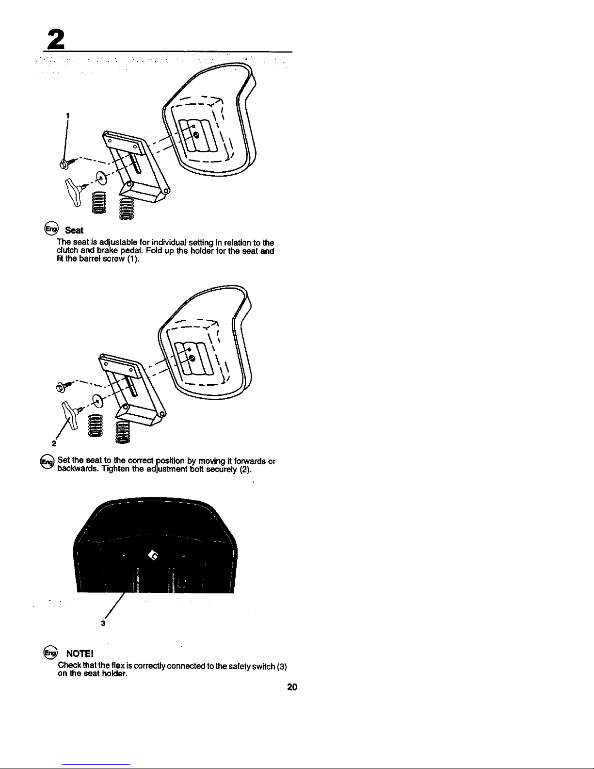
_Seat
The seat isadjustableforindividualsettingin relationtothe
clutchandbrake pedal. Foldup the holderfor theseat and
fitthe barrelscrew (1).
_Set the seat to the correct position by moving it forwards or
backwards, Tighten the adjustment bolt securely (2).
/
3
NOTE!
Checkthatthe flexiscorrectlyconnectedtothesafetyswitch(3)
onthe seat holder.
20
Page 10
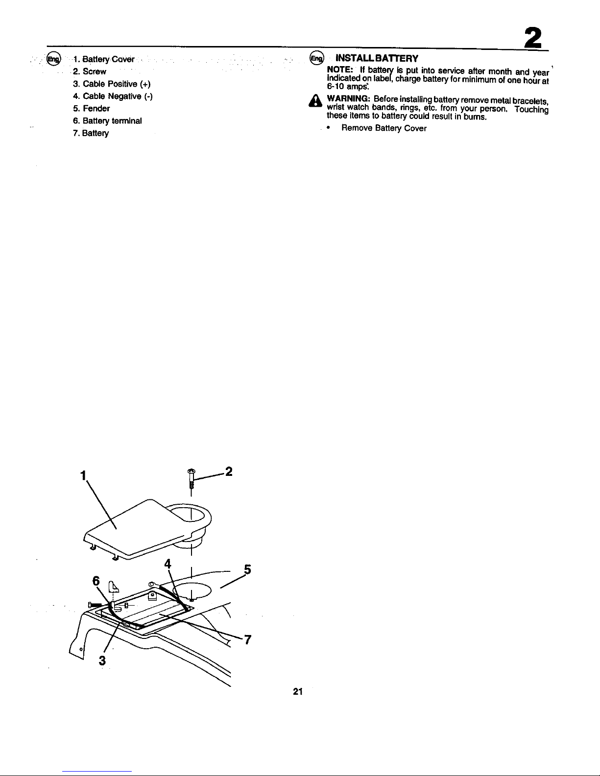
• .:_) .t. BattenjCover
2. Screw
3, Cable Positive (+)
4. Cable Negative (-)
5. Fender
6. Battery terminal
7. Battery
2
INSTALL BATTERY
NOTE: If battery is put into service after month and veAr'
indicated on label, charge battery for minimum of one hour at
6-10 amps'.
,_ WARNING: Before installing battery remove metal bracelets,
wrist watch bands, rings, etc. from your person Touching
those terns to battery could result in bums.
• Remove Battery Cover
4
o J
3
21
Page 11
2
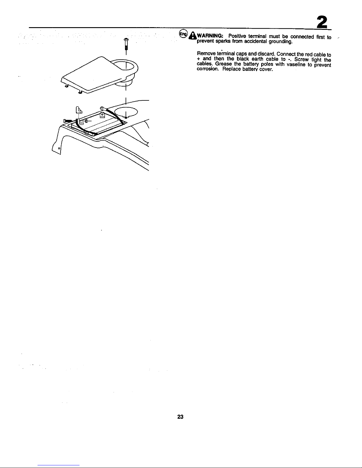
_)_WARNING: Positiveterminal must be connected first to
preventsparksfrom accidentalgrounding.
Removeterminalcapsanddiscard.Connecttheredcableto
+ and then the black earth cable to -. Screw tight the
cables.Grease the batted/poleswith vaseline to prevent
corrosion. Replacebatten/cover.
23
Page 12

2
To install bagger oomponents to tractor
1. Discharge Chute
2. 3/8Nut "%# 2..,.,.,_. -. -.
3. FlatWasher - / ,_'_
3"
Removedischargechutefromrearoftractor. Unhook the
two(2) strapsand pullchuteoutandawayfrom tractor.
Removethetwo(2)3/8 nutsandflat washersfromthebolts
at thetractorbackplate.
1. 3/8 Locknut
2. FlatWasher
3. SupportTube
2_
1-_--.
Using the nuts and flat washers removed from tractor back
plate, install the bagger support tube to the back plate as
shown. Tighten securely.
1. Rear Door
4
4
2. Support Bracket
3. 3/8 Carriage Bolt
4. 3/8 Lock Nut
2
5. 3/8 x 63,5mm Hex Bolt
6. 10,3mm (13/32") flat 6
was'her
• While holding the rear door open, install the two upper
support I_rackets through the back plate and to the chas-
sis, using the 3/8 x 19mm carriage bolts and Iocknuts
supplied. Tighten securely.
• Assemble both support brackets to the outside of the
baggger support tube using two each 3/8 x 63 5mm hex
bolts13/32" I.D. flat washers and 3/8 Iocknuts from parts
bag. Tighten securely.
1.
2.
3.
Hook
Discharge
Back plate slot
3
• Replace discharge chute into rear opening of tractor.
, Secure the chute with the two hook straps.
NOTE: The strap hook must go through the discharge chute
only. Do notallow the hook toenter the slotin the tractor back
plate. This will allow the discharge chute to float with the
mower deck when moving on uneven terrain.
24
Page 13
: L 1 ¸-2¸¸ ....
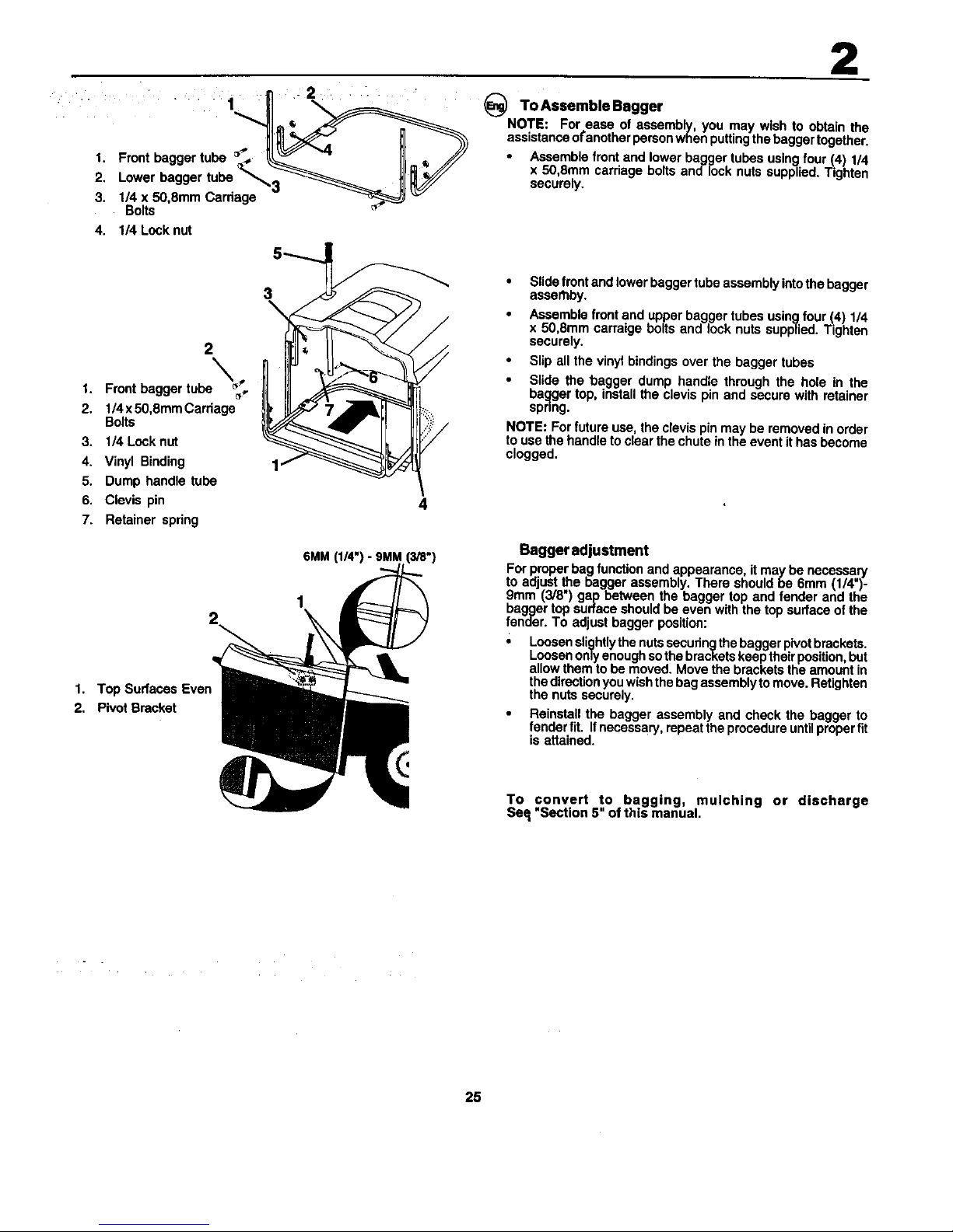
1. Front bagger tuba
2,oworbaggertuba' ',.
3. 114 x 50,8mm Carriage - _ "_
Bolts
4. 1/4 Lock nut
2
1. Frontbaggertuba _.
2. 1/4x50,8mmCarriage
Bolts
3. l_Leckn_
4. Vinyl Binding
5. Dumphandle tuba
6. Clevispin
7. Retainer spdng
2
To Assemble Bagger
NOTE: For ease of assembly you may wish to obtan the
assstanceofanotherpersonwhenputtingthebaggertogether,
Assemblefrontand lowerbaggertubasusingfour(4)1/4
x 50,8ram carriageboltsand locknutssupplied.Tighten
securely,
/
• Slidefrontandlowerbaggertubeassemblyintothebagger
asse_by.
• Assemblefrontand upperbaggertubesusingfour ._4)1/4
x 50,Smmcarraigebolts and lock nutssupplied.Tighten
securely.
• Slipall the vinylbindingsover the baggertubes
• Slide the bagger dump handle throughthe hole in the
baqgertop,installtheclevispinand securewith retainer
spring.
NOTE: Forfutureuse,theclevispin maybe removedinorder
tousethehandletoclearthechuteintheevent ithas become
clogged.
4
1. Top Sudaces Even
2. Pivot Bracket
6MM
1
2
Bagger adjustment
For proper bag function and appearance, it may be necessary
to adjust the bagger assembly. There should be 6mm (1/4")-
9mm (3/8") gap between the bagger top and fender and the
bagger top surface should be even with the top surface of the
fender. To adjust bagger position:
• Loosen slightlythe nuts secudngthe bagger pivot brackets.
Loosen only enough so the brackets keep theirposition, but
allow them to be moved. Move the brackets the amount in
the directionyou wish the bag assembly to move. Retighten
the nuts securely.
Reinstall the bagger assembly and check the bagger to
fender fit. IfnecessarY, repeat the procedure until proper fit
is attained.
To convert to bagging, mulching or discharge
Seq"Section 5" of this manual.
25
Page 14

2
ASSEMBLE GAUGE WHEELS
Checkthatthe requiredcuttingheightis obtained.
36
Page 15
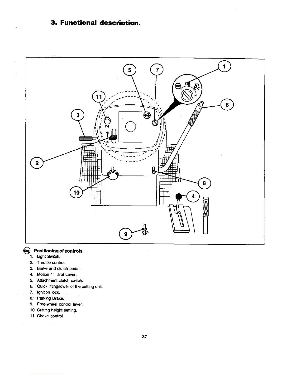
3. Functional descrintion.
©
_) Positioning of controls
1. Light Switch.
2. Throttle control.
3, Brake and clutch pedal.
4. Motion r _trol Lover.
5. Attachment clutch switch.
6, Quick lifting/lower of the cutting unit.
7. Ignition lock.
8. Parking Brake.
9, Free-wheel control lever,
10. Cutting height setting.
11. Choke control
37
Page 16
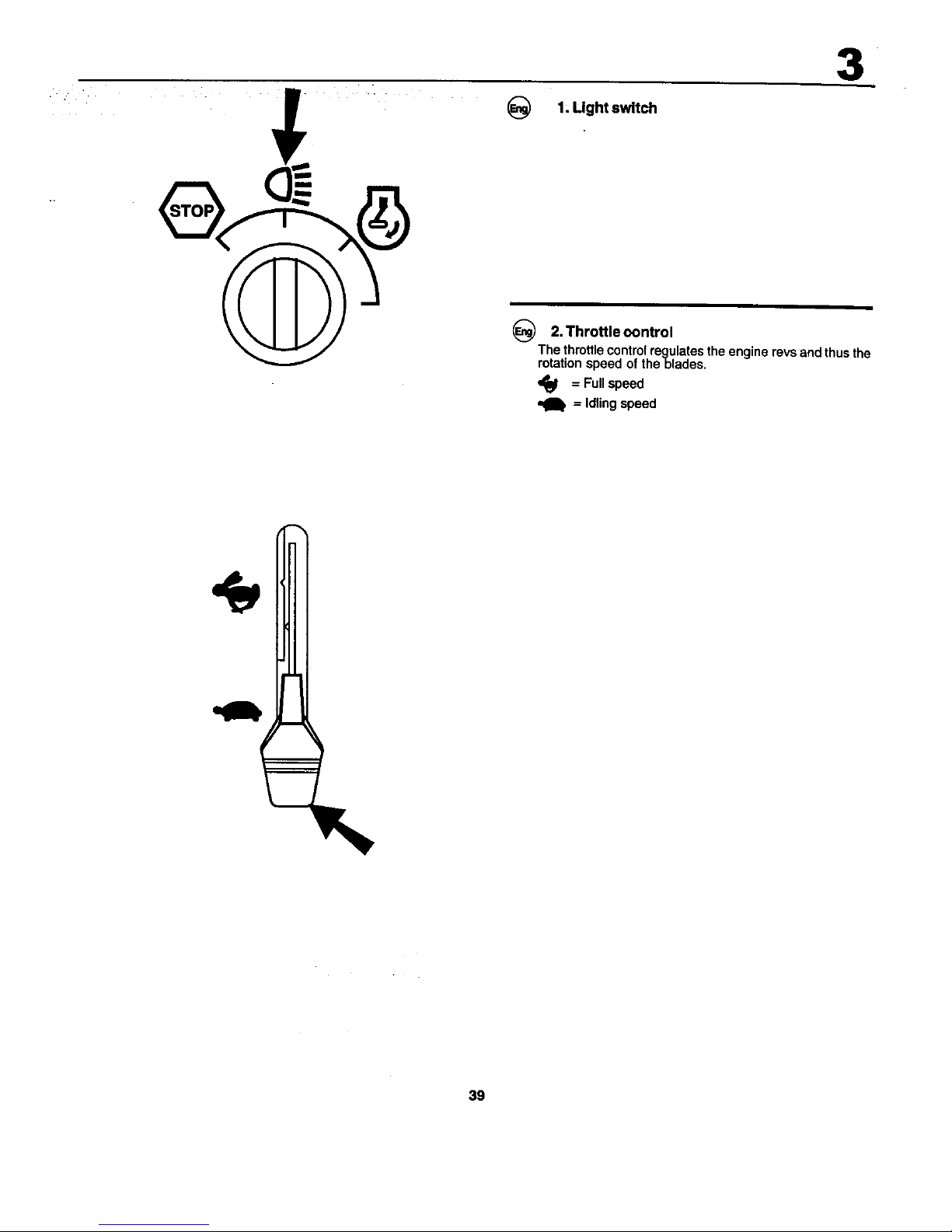
1, Light switch
3
_) 2. ThrotUe oontrol
The throttle control regulates the engine revs and thus the
rotation speed of theblades,
,_ = Full speed
= Idling speed
39
Page 17

3
3. Brake and clutch pedal
When the pedal is pushed down the brake is applied and the
motor is d_sengaged.
40
Page 18

3
S
N
4. Motion control lever
Thereare fourdifferentpositionsforthislever:
N = Neutral(no drive)
S = Slow
F= Fast
R = Reverse
The levercanbe movedsteplesslybetweenSandFtoensure
the requiredspeed.
41
Page 19

3
5. Attachment clutch switch
of the cutting unit
6. Quick
lifting/lowering
Pullthe lever backwardstoquicklyliftthe cuttingunitwhen
passingoverirregularitiesinthe lawn.etc.Durin_transporta-
tionthe cuttingunit shallbe in the highestposihon,Pullthe
lever back until it locks.To lower the unit:Pull the lever
backwards(1), Pushinthebutton(2)andthenmovethelever
forwards(3).
42
Page 20

OFF ON START
3
7. Ignition Lock
There are three different positions for the ignition key:
OFF All electdc current broken,
ON Electdc current connected,
START Start motor connected.
WARNING!
Never leave the key in the ignition rock when leaving the
machine on its own.
8. Parking brake
Connect the parking brake in the following way:
1. Press down the rake peda! to bottom position.
2. Move the parking brake lever upwards and hold in this
position.
3. Release the brake pedal,
To release the parking brake all that is necessary is to push
down the brake pedal.
43
Page 21

3
_) 9, Free-wheel Control Lever
Totowormovethetractorwithouttheaidoftheenginethefree-
wheelcontrolknobmustbepu ed outand lockedinposition.
44
Page 22

3
10. Cutting height setting
The requiredcuttingheightissetwiththe aidofthe wheel,
The cuttingheight is increasedwhen itisturnedclockwise.
The whee/is easierto turnifthe leverfor lifUng/Iowedngof
thecuffingunitispulledbackwardsat thesame time,
11. Choke control
When the engine is cold the choke should be pulled out
before starting. When the engine has started and is running
smoothly push the choke in.
45
Page 23

4. Before starting.
Filling up
The engineshouldbe runof pure (not oil mixed) unleaded
petrol.Do notfillbeyondthe loweredgeofthefilling hole. Do
notfill over max level.
WARNING!
Petrolishighlyinflammable.Proceedwithcareandfill upwith
petroloutdoors.Do not smokewhenfilling withpetrolorfill up
whenthe engine is warm. Do notoverfillthetank sincethe
pertrolcanexpandandoverflow.Make surethatthepetrolcap
securelytightenedafterfilling. Storepetrolin a cool place
inan appropriatecontainerfor enginefuel. Checkthe petrol
tankand pipes.
46
Page 24

4
_) OII level
The combined oil refilling cap and the oil stick is accessible
when the bonnet is lifted forwards. The oil level in the engine
should be checked before each run. Make sure that the tractor
is horizontal. Unscrew the oil stick and wipe clean. Replace
the oilstickand screw tiQht.Remove again andcheck thelevel.
_)The oillevelshouldlie betweenthetwo markingsonthe o
stick.If moreoilis needed add SAE 30 oiltothe FULL"
marking.SAE 5W-30 oil shouldbe usedduringthe winter
(belowfreezing point).
ADD "-=
*--FULLCAUTION - DO
47
Page 25

4
Tire air _)ressure
Checkthetyre pressureregularly.The pressureinthefront
tyresshouldbe1bar(14PSI) and0.8 bar(12 PSI) intheback
tyres.
48
Page 26

• • • • .
5. Driving.
Starting of motor
Makesurethatthe cuttingunitisinthetransportposition(top
position)and thatthe lever for connection/disconnectionof
the cuttingunit is inthe disconnectionposition.
_) Press down the clutch/brakepedal completelyanO hold
down,Set the motioncontrollever in neutral"N*.
_Pull out the choke control (if engine is co d)
49
Page 27

5
_Warm motor: Pushthe gas controlhalf-wayto fullgas$
po_lfion",,_".
_)Tum the ignition key to "START position',
NOTE!
Do n_ mnthe mad motormomMan 5seconds = once.If
the enginewillnotstart, waitaboutl0secondsbefom the
ne_tw.
Q When the engine has started let the ignitionkeygo back to
the "ON posttion_. Push the gas control to the required
speed, For cutting: full gas.
50
Page 28

5
• • _) [MPORTANTI COLDSTARTING FOR HYDRO i
IMPORTANT: cOLD STARTING FOR HYDRO (BELOW
4O°F[4°C]) - AFTER STARTING ENGINE AND BEFORE
DRIVING, LET TRANSMISSION WARM UP FOR ONE(1)
MINUTEBY PLACING MOTION CONTROL LEVER INNEU
TRAL (N) POSITION AND RELEASING CLUTCH/BRAKE
PEDAL,
• Disengagetransmissionbyplacingfreewheelcontrolin
freewheelingposition.
• StadengineandmovethrotUecontroltoslowposition.Be
sure parkingbrakeis not engaged.
• Move motioncontrolleverto full forward positionand
hold for five (5) seconds. Move lever to full reverse
positionand hold for five (5) seconds. Repeat this
procedurethree(3) times•
• Move motioncontrolleverto neutral(N) position.
• Stoptractorbytumingignitionkeyto"OFF"position.
• Engage transmissionby placing freewheel controlin
drivingposition.
• Startengineand movethrottlecontrolto slowposition.
• Drive tractorforward for approximatelyfive feet then
backwardsfor,five feet• Repeat thisdrivingprocedure
threetimes.
Your tractor is now ready for normal operation.
_) PURGETRANSMISSION
To ensure proper operation and performance, it is recom
mended that the transmission be purged before operating
tractor for the first time. Th s procedure will remove any
• trapped air inside the transmission which may have devel-
oped during shipping of your tractor.
IMPORTANT: SHOULD YOUR TRANSMISSION REQUIRE
REMOVAL FOR SERVICE OR REPLACEMENT, ITSHOULD
BE PURGED AFTER REIN STALLATION BEFORE OPER-
ATING THE TRACTOR.
Park tractor on level surface so it will not roll in any
direction. Parking brake must be disengaged for the
following procedure.
51
Page 29

5
• "t'----_: NOTEI .....
= The machine is equipped with a safety Switch which
immediately breaks the current to the engine if the driver
leaves the seat with engine running and with the connec-
tion/disconnection lever in position "connection".Your
machine is also equiped with a system that will not allow
mower to operate if the bagger or optional rear discharge
deflector is not installed properly.
Driving
Warm up the engine for a few minutes with the throttle
athalf-speed. Lower the cutting unit by moving the lever
forwards, Release the brake/clutch pedal slowly. Connect
the cutting unit and move the motion control lever to the
requireposition.
53
Page 30

5
_Move the t_orottlecontrolto fullspeed (_). Choose a driving
speed which suits the terrain and requ=radcutting results.
Cuttingtips
• Clearthelawnfromstonesand otherobjectswhichcan
be thrownaway by the blades.
• Localizeand mark stones and other fixed objectsto
avoid collision,
• Begin with a high cuttingheight and reduce untilthe
requiredcuttingresultis obtained.
• The cuttingrosultisbestwithhighenginespeed(blades
rotatequickly)and Iowgear(machinegoesslowly).Ifthe
grass is too long and thick the drive speed can be
fncreasedby selectinga highergear or reducingthe
motorspeed,withoutaffectingthe cuttingresult.
• The bestlawnisachievedifthegrassiscutoften.Cutting
becomesmore even and the cutgrass is more evenly
distributedover the surface. Total time taken is not
greater since higher drive speed can be selected
withoutaffectingthe cuttingresuis.
• Avoidcuttingwet grass.The cuttingresultswillbeworse
sincethe wheels willsinkintothe softlawn.
• Spraythecuttingunitwithwater underneathafteruse.
54
Page 31

5
Dump Bagger
To
Yourtractorisequippedwitha Dump BagAlarm.Totum off
the alarm disengagethe attachmentclutchswitch.
• Positiontractorin locationyouwishto dump bagger.
Place motioncontrol lever in Neutral positionand set
parking brake.
• Raise dump handleto its highestposition.Pull handle
forward to raisebagger and dumpclippings.
• To continuemowing, be sure bagger is down and in
proper operatiz_:_positionwhich will allow mower tv
operate.
56
Page 32

5
' :(_-_ Toconvert mower
Convertingto mulchingorreardischargingwillrequirethe
purchaseofthese accessories.)
To mulching
• Placedeck into thehighcut position.
• Remove baggeror optionalrear dischargedeflector.
Unhookthe two(2) strapsandremovedischargechute
Insert plug and hartdteassemblythroughback plate
and ontothe mowerdeckchute adaptor,
• Retaintheplugassemblybyconnectingthetwo straps
overthe handleand hook intothe holes provided.
• Replacebaggeroroptionalreardischargedeflectorto
allowmowerto operate.
You are now ready to begin mulching.
To rear discharging
• Placedeck Into the highoutposition.
• Remove baggerand mulchingplug (if installed).
• Installdischargechutethroughopeningin backplate
and slide over deck adaptor•
• Attachthe chute by hookingthe two straps into the
holesin the flange ofthechute.
• Installthe discharge deflectorto the backplate by
screwing thefour (4) wing screws intothe threaded
insertslocatedin the backplate.
• Tightenthe wing screwssecurely.
To bagging
• Placedeck intothe highcut position.
• Removethereardischargedeflectorormulchingplug,
Insert the dischargechute into the opening in the
backplate and ontothe mowerdeck adaptor.
Attachthechutetothetractorby hooldngthetwostraps
tothe flange of thechute.
• Installbaggerintotractor.
57
Page 33

5
=
WARNING!
• Do notdriveinterrainatan angleofmorethanmax.10°.
The riskfor spark-overbackwardsislarge.
• In steepterrainthe riskfor tippingis considerable.
• Avoidstoppingand startingin slopingterrain.
• Onlychangegear whenthe machineisstandingstillto
avoiddamaging thegear box.
59
Page 34

5
_Use the left side ofthe machine to cut close to trees, bushes
and paths, etc. The blade cuts about 15 mm inside the edge
of the cover.
Switching off the engine
Movethegascontrolto=NIb".
Disconnectthecuttingunitby movingthe connect/discon-
nectlever downwards.
Liftup the cuttingunit and turn the ignitionkey to =OFF"
position.
Allowthe engineto idlefor 1-2 minutestocooldownbefore
switchingoffafter a hardwork.
60
Page 35

6. Maintenance, adjustment•
WARNING!
Beforeservicingthe engineor cuttingunitthe following
shallbe carriedout:
• Switchoffengine.
• Putgear leverin neutral,
• Moveconnection/disconnectionlevertodisengaged
position.
• Pressdown the clutch/brakepedal and engagethe
parkingbrake lever.
• Removethe ignitioncable from the plug.
(1) Hood
(2) Headlight wire connector
@
Engine hood
• Raise hood.
• = U _snap head!ight wire connector.
S and infront ,)'.tractor. Grasp hood at sides, tiltforward
an., lift offof b _ctor.
• To reinstall, sl ce hood pivotbrackets into slots in frame.
• Reconnect h_dlight wire connector and close hood.
62
Page 36

Malntenance_
NOTE: Periodic maintenance should be performed on a
regular basis in order to keep your tractor in good running
condition.
_ WARNING: Disconnectsparkplugwiretopreventacciden-
tal startingbefore attemptingany repair, inspection, or
maintenance.
Before each use:
• Check oil, lubricate pivot points as necessary.
• Check to see all bolts, nuts, and cotter pins are in place
and secure.
• Check the battery, terminals and vents.
• Recharge slowly at 6 amperes if needed.
• Clean air screen.
• Keep tractor free of dirt'and chaff to prevent engine
damage or overheating.
• Check brake operation.
64
Page 37

Service Record
Fill in dates as you complete regular service
Change engine oil
Lubricatepivot points
Check brake operation
Clean air screen
Clean air filterand pre-cleaner
Replaceair cleaner paper cartridge
Clean enginecoolingfins
Replace spark plug
Check tire pressure
Replace fuelfilter
Clean batteryand terminals
Check muffler
Lubricateball joints
Tce-in adjustment
Carburetoradjustment
JnA'_eeded
Every 8
hours
Every
25 hours
Every
50 hours
Every
100hours
Every
200hours
6
66
Page 38

6
!/_) Blades
The blades should be sharp to achieve best cutting results,
Sharpening can be carded out with a file or gdnding disc.
NOTE!
It isvery important that both blades are sharpened equally to
avoid imbalance.
VIEW FROM BOTTEM OF MOWER DECK
@
BladeCare
Important: The blades on your mower are not the same and
must be installedon the correct side. It issuggested that you
work on one blade at a time to ensure proper assembly of
components,
I
1.
5-Star patternbladew/right
hand threadedbolt
2,
_ 6-Star pattem blade w/left
hand threaded bolt
69
Page 39

6
8
_) 5 Star pattern blade
Thecenterofthisbladehasafive(5)starpattern.Theboltthat
attachestkis blade has normal Right Hand threads that
loosensby tumin_](u) counter-clockwiseand tightensby
turning(z) clockwMse.
6
\
_) I. Hext_righthandthmaded.
2, Lock Washer
3. Flat Washer
4. Blade
5. 5 StarCe_er Hole
6, 5 StarPattern
7. TrailingEdge
8. MandrelAssembly
_1. Hex bolt leRhand
threa_ed.
2. LockWSsher
3. FiatWasher
4. Blade
_'7 8
5. 6 StarCenterHole
6. 6 Star Pagem
7. TrailingEdge
8. MandrelAssembly
6 Star pattern blade
Thecenterofthisbladehasa6starpattem.Theboltattaching
thisbtadehasLeftHand threadsthat loosens by turning(z_
clockwiseand tightenby turning(u) counterclockwise.
70
Page 40

_) For best results mower blades must be kept sharp. Re-
"_" place bent or damaged blades.
BLADE REMOVAL
• Raise mower to highest position to allow access to
blades.
Remove hex bolt, lock washer and flat washer secur-
ing blade.
Instan new or msharpened blade with trailing edge up
towards deck as shown.
Important: To ensure proper assembly, center hole in
blade must align with star on mandrel assembly.
• Reassemble hex bolt, lock washer and flat washer in
exact order as shown.
• Tighten bolt securely (27-35 Ft. Lbs. torque).
6
72
Page 41

Brakes
The brakesarelocatedinsidethe rightrearwheel.Thewheel
shouldbe dismantledfor best access.
1. Press down the clutch/brakepedal and engage the
parkingbrake.
1. Measure the distance between the brake lever and the
adjuster nut.
2. The distance should be 40 mm (1.56").
3. Ad ust the distance if necessary by first loosening the
nck nut (2) and then adjusting with the nut (1).
WARNING!
Do not forget to tighten the lock nut after complet-
ingadjustment.
73
Page 42

6
¸
I• ¸
Dismantling of the cutting unit
Work from the right side of the machine.
1, Take off the belt from the engine pulley (1).
2. Rar_ove the two rear retainer springs (2) and knock off
the axle taps with a hammer,
74
Page 43

6
_)3. Removethe retainersprings(3), (4), (5) and axles.
4. Pull the lever for lifting/loweringthe cuttingunit back-
wards.
5. Pulloutthecuttingunitfrom the machine.
_) Assembly of the unit
cutting
Assemble in the reverse order to dismantling,
• Push in the cutting unit under the machine. The ejector
opening should be to the right.
75
Page 44

6
Replacement of drive belt for cutting unit
1. Dismantle the cutting unit as described pmviousley.
2. Work offthe belt from the unit's left pulley and then from
the other wheels.
3, Pull the belt away from the cutting unit.
4. The new belt is mounted in the reverse order. Check that
the belt lies inside all the belt guides,
76
Page 45

6
_) Adjustment of the cutting unit
A. In the direction of travel
1. Checkthat theair pressureis correctinallfourlyres.
2. Makesure thatthe machineis on a hodzontalsurface.
3, Liftupthe cuttingunitto its highestposition.
4. Measurethe distancesA and B.
_)To achievebestcuttingresultsthecuttingunit'sfrontedge(B)
shouldbe about 10 mm (0.375) lowerthanthe backedge
(A). Adjustin the followingway to raisethe backedge:
1. Loosenthe nut(1) on boththe left and rightlevers.
2, Screw the nut (2) the same numberof turn s on both
levers.
3. Whenthecorrectdistance(A) is obtainedthissettingis
lockedwiththe nut (1).
77
Page 46

_(1) Bottom edge of mower
(2) Lift link adjustment nut
6
_ SIDE-TO-SIDE ADJUSTMENT
• Raise mowerto highestposition.
• Atthe midpoint of bothsidesof mower,measureheight
from bottom edge of mowerto ground. Distance A
shouldbe the sameor within6ram(1/4") ofeach other.
• Ifadjustmentis necessary,makeadjustment ononeside
of moweronly.
• To raiseonesideofmower,tightenliftlinkadjustmentnut
onthatside.
• To Iowerone side of mower, loosen liftlinkadjustment nut
on that side.
NOTE: Three funtums of adjustment nut willchange mower
height about 1/8".
• Recheck measurements after adjusting.
7!
Page 47

6
Replacement of drive belt
1. Dismantle the cutting unit as described previously.
2. Pull apad the contactfor the cable to the electrical connec
tion (1).
3. Dismantle the motion restrainer for the clutch (2).
4. Engage the parking brake and work off the belt upwards
from the pulley (3), the clutch pulley (4).
5. Push the belt up between two fan blades and rotatethe
fan clockwise until the belt comes loose (5).
6. Take off the be_tfrom the engine pulley.
_ Assembleinthereverseordertodismantling.Checkthatthe
beltliesinsideallthebeltguides.Useodgina]beltsonlywhen
repiacingt
79
Page 48

6
_1. Motion Control Lever
2. Neutral Lock Gate
3, Adjustment Bolt
_) TRANSAXLE MOTION CONTROL LEVER NEU-
TRAL ADJUSTMENT
The motioncontrollever has been presetat thefactory and
adjustmentshouldnot be necessary.
• Loosenadjustmentboltin frontofthe rightrear wheel,
and lightly tighten.
• Startengineand movemotioncontrolleveruntiltractor
does notmoveforward or backward.
Holdmotioncontrolleverinthatpositionand tumengine
off.
• Wi "- holding motioncontrollever in place,loosenthe
aOlustmentbolt.
• Movemotioncontrollevertothe neutral(N) (lockgate)
position.
• Tightenadjustmentbolt securely.
NOTE: Ifadditional•clearanceisneededtogetto adjustment
bolt movemowerdeck heightto the lowestposition.After
aboveadustment is made, t!thetractorstillcreepsforward
orbackwardwh e motioncontrol leverisinneutral position.
followthese steps:
• Loosenthe adjustF,_entbolt.
Move the motionconLrellever 114to 1/2 inch in the
directionitistryingto creep.
• Tightenadjustmentbolt securely.
• Startengineand test.
Iftractorstillcreeps, repeatabovestepsuntilsatisfied.
8O
Page 49

The fan and cooling fins oftransmission shouldbe kept clean
to assure proper cooling.
Do not attempt to clean fan or transmission while engine is
running or while the transmission is hot.
Inspect cooling fan to be sure fan blades are intact and
clean.
• inspect cooling fins for dirt, grass clippings and other
materials,
TRANSAXLE PUMP FLUID
The transaxle was sealed at the factoryand fluid mainte
nance is not required. Shouldthe transaxleever leak or
requireservicing,contact your nearestauthorizedservice
center/department.
6
82
Page 50

7. TROUBLESHOOTING.
_J Engine will not start
1. Nofuelin fueltank.
2, Plug defecUve.
3. Plug connectiondefective.
4. Dirtincarburettoror fuel pipe.
Start motor will not turn engine
1. Batteryfiat.
2. Poor contact between cable and battery pole.
3. Connection/disconnection level in wrong po6ition.
4. Main fuse defective.
5. |gnition took defective.
6. Safety contact for clutch/brake pedal defective.
7, Clutch/brake pedal not pushed down,
Engine runs unevenly
1. Gear too high.
2. Plug defective.
3, Carburettor incorrectly set,
4. Air filter blocked.
5, Fuel tank ventilation blocked,
6. Ignition setting defective,
7. Dirt in fuel pipe.
Engine feels weak
1. Air filter blocked.
2. Plug defective.
3. Dirt in carburettor or fuel pipe,
4, Carburettor incorrectly set.
Engine overheats
1. Engine ovedoaded.
2. Air inlet or cooling fins blocked.
3. Fan damaged.
4. Too little or no oil in engine.
5. ignition setting defective.
6. Plug defective.
Battery does not charge
1. Fuse defective,
2. One or several cells defective.
3. Poor contact between battery poles and cables,
Lighting does not function
1. Bulbsdr: ,'ctive.
2. Switchdefective.
3, Short-circuitin cable.
The machine vibrates
1. Blades loose.
2. Engine loose.
3. Unbalance in one or both blades resulting from damage
or poor balancing after sharpening.
Uneven cutting results
1. Blades blunt.
2, Cutting unit skew,
3. Long or wet grass.
4. Grass stuck under cover.
5. Different air pressures in lyres on left and right side.
6. Gear too high.
7. Drive belt slipping.
83
Page 51

8. STORAGE.
_)The following steps should be taken when mowing season
is over:.
Clean the entire machine, especially undemeath the
cutting unit cover.
• Touch.up all chipped paint surfaces in order to avoid
corrosion.
• Change engine oil.
• Drain the fuel tank. Start the engine andallowit to rununtil
it is out of fuel.
• Remove the spark plug and pour one table spoon of
engine oil into the cylinder. Pull the engine over in order
to distribute the oil. Retum the spark plug.
• Remove the battery. Recharge and store itina cool dry
place. Protect the batter_ from low temperatures.
• The machine should be stored indoors in a dry, dust-free
place.
WARNING!
Never use gasoline when cleaning.Use degreasingdeter
gentand warm water instead.
Service
When ordering, we need the following information:
Date ofpurchase, model, type and serial number of the
mower. Always use original spare parts. Contact your local
dealer of distributor for warranty service and repairs.
86
Page 52

CRAFTSMAN"
168732 flev. 2 4.21.99 VB/RDIflH Printed in U.S.A.
 Loading...