

Page 1

CRAFTXMnN°
25915
Instruction manual
Please read these instructions
carefully and make sure you
understand them before using this
ma_hin_
Page 2
1
2
3
4
Safety specifications.
Sicherheitsbestimmungen.
Consignes de securitY.
Assembly.
7usammenbau.
Montage.
Functional description.
Funktionsbeschreibung.
Description du fonctionnement. __
Procedure before start.
MaBnahmen vor dem Anlassen.
Avant de demarrer.
Driving.
Betrieb.
Conduite.
6
7
8
Maintenance, adjustment.
Instandhaltung, Einstellung.
Entretien, reglages.
Faulttracing.
StSrungssuche.
Recherche des pannes.
Storage.
Aufbewahrung.
Rangement.
We reserve the right to changes without prior notice.
2
Page 3
1. Safety Rules
Safe Operation Practices for Ride-On Mowers
IMPORTANT: THIS CUTTING MACHINE IS CAPABLE OF AMPUTATING HANDS AND FEET AND THROWING OBJECTS.
FAILURE TO OBSERVE THE FOLLOWING SAFETY INSTRUCTIONS COULD RESULT IN SERIOUS INJURY OR DEATH.
O I. Training
Read the instructions carefully. Be familiar with the
controls and the proper use of the equipment.
Never allow children or people unfamiliar with the ins-
tructions to use the lawnmower. Local regulations may
restrict the age of the operator.
Never mow while people, especially children, or pets are
nearby.
Keep in mind that the operator or user is responsible for
accidents or hazards occurring to other people or their
property.
All drivers should seek and obtain professional and
practical instruction. Such instruction should empha-
size:
- the need for care and concentration when working
with ride-on machines;
- control of a ride-on machine sliding on a slope will
not be regained by the application of the brake.
The main reasons for loss of control are:
a) insufficient wheel grip;
b) being driven too fast;
c) inadequate braking;
d) the type of machine is unsuitable for its task;
e) lack of awareness of the effect of ground
conditions,especially slopes;
f) incorrect hitching and load distribution.
II. Preparation
While mowing, always wear substantial footwear and
long trousers. Do not operate the equipment when
barefoot or wearing open sandals.
Thoroughly inspect the area where the equipment is to
be used and remove all objects which may be thrown by
the machine.
WARNING - Petrol is highly flammable.
- Store fuel in containers specifically designed for this
purpose.
- Refuel outdoors only and do not smoke while refu-
eling.
- Add fuel before starting the engine. Never remove
the cap of the fuel tank or add petrol while the engine
is running or when the engine is hot.
If petrol is spilled, do not attempt to start the engine
but move the machine away from the area of spillage
and avoid creating any source of ignition until petrol
vapors have dissipated.
- Replace all fuel tanks and container caps securely.
Replace faulty silencers.
Before using, always visually inspect to see that the
blades, blade bolts and cutter assembly are not worn or
damaged. Replace worn or damaged blades and bolts
in sets to preserve balance.
On multi-bladed machines, take care as rotating one
blade can cause other blades to rotate.
III. Operation
Do not operate the engine in a confined space where
dangerous carbon monoxide fumes can collect.
Mow only in daylight or in good artificial bight.
Before attempting to start the engine, disengage all blade
attachment clutches and shift into neutral.
Do not use on slopes of more than 10°.
Rememberthere is no such thing as a "safe" slope. Travel
on grass slopes requires particular care. To guard
against overturning;
- do not stop or start suddenly when going up or
downhill;
- engage clutch slowly, always keep machine ingear,
especially when traveling downhill;
- machine speeds should be kept low on slopes and
during tight turns;
- stay alert for humps and hollows and other hidden
hazards;
- never mow across the face of the slope, unless the
lawnmower is designed for this purpose.
Use care when pulling loads or using heavy equipment.
Use only approved drawbar hitch points.
Limit loads to those you can safely control.
Do not turn sharply. Use care when reversing.
- Use counterweight(s) or wheel weights when sug-
gested in the instruction handbook.
Watch out for traffic when crossing or near roadways.
Stop the blades from rotating before crossing surfaces
other than grass.
When using any attachments, never direct discharge of
material toward bystanders nor allow anyone near the
machine while in operation.
Never operate the lawnmower with defective guards,
shields or without safety protective devices in place.
Do not change the engine governor settings or overspeed
the engine. Operating the engine at excessive speed
may increase the hazard of personal injury.
Before leaving the operator's position:
- disengage the power take-off and lower the attach-
ments;
- change into neutral and set the parking brake;
- stop the engine and remove the key.
Disengage drive to attachments, stop the engine, and
disconnect the spark plug wire(s) or remove the ignition
key
- before cleaning blockages or unclogging chute;
- before checking, cleaning or working on the
lawnmower;
- afterstrikingaforeignobject. Inspectthelawnmower
for damage and make repairs before restarting and
operating the equipment;
- if the machine starts to vibrate abnormally (check
immediately).
Disengage drive to attachments when transporting or not
in use.
Stop the engine and disengage drive to attachment
- before refueling;
- before removing the grass catcher;
- before making height adjustment unless adjust-
ment can be made from the operator's position.
Reduce the throttle setting during engine run-out and, if
the engine is provided with a shut-off valve, turn the fuel
off at the conclusion of mowing.
3
Page 4
IV. Maintenance and Storage
Keep all nuts, bolts and screws tight to be sure the
equipment is in safe working condition.
Never store the equipment with petrol in the tank inside
a building where fumes may reach an open flame or
spark.
Allow the engine to cool before storing in any enclosure.
To reduce the fire hazard, keep the engine, silencer,
battery compartment and petrol storage area free of
grass, leaves, or excessive grease.
Check the grass catcher frequently for wear or deteriora-
tion.
Replace worn or damaged parts for safety.
If the fuel tank has to be drained, this should be done
outdoors.
On multi-bladed machines, take care as rotating one
blade can cause other blades to rotate.
When machine is to be parked, stored or left unattended,
lower the cutting means unless a positive mechanical
lock is used.
CAUTION: Always disconnect spark wire and
plug
place wire where it cannot contact spark plug in
order to prevent accidental starting when setting up,
transporting, adjusting or making repairs.
4
Page 5

_) These symbols may appear on your tractor or in the literature supplied with the product. Learn and understand their meaning.
R N H L "_ (]_ Q
REVERSE NEUTRAL HIGH LOW FAST SLOW LIGHTS ON UGHTS OFF
ENGINE ON ENGINE OFF PARKING BRAKE LOCKED UNLOCKED .PARKING BRAKE BA'i-rERY
I
CLUTCH CHOKE FUEL OIL PRESSURE DIFFERENTIAL LOCK REVERSE FORWARD
IGNITION ATTACHMENT ATI*ACHMENT CAUTION MOWER HEIGHT BEWARE OF
CLUTCH ENGAGED CLUTCH DISENGAGED THROWN OBJECTS
15
Page 6
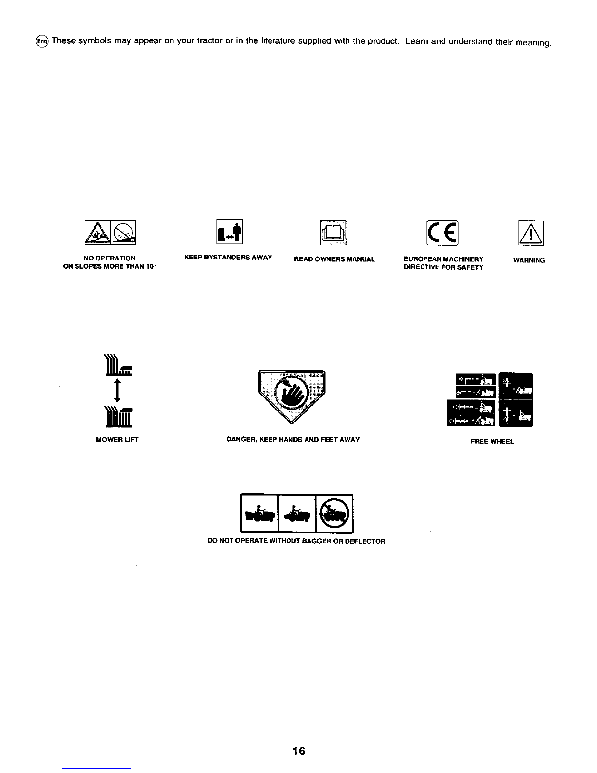
_) These symbols may appear on your tractor or in the literature supplied with the product. Learn and understand their meaning.
NO OPERATION KEEP BYSTANDERS AWAY READ OWNERS MANUAL EUROPEAN MACHINERY WARNING
ON SLOPES MORE THAN 10° DIRECTIVE FOR SAFETY
L
MOWER LIFT
DANGER, KEEP HANDS AND FEET AWAY
FREE WHEEL
DO NOT OPERATE WITHOUT BAGGER OR DEFLECTOR
16
Page 7

EXPLOSIVE GASES I -SPARKS
CAN CAUSE BLINDNESS .FLAMES
OR LNJURY, I -SMOKING
[_ FLUSH EYESIMMEDIATELY WITH
SULFURIC ACID WATER. (_
;ANCAUSE HELP FAST. ,,_(_
BLINDNESS OR
SEVERE BURNS.
RECYCLE
Mfg. byJ
EPM Products
Baltimore, MD 21226
MADE IN U,S.A.
17
Page 8
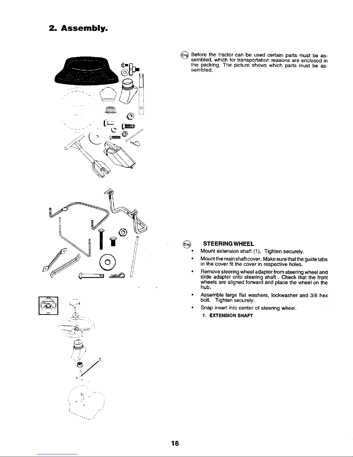
2. Assembly.
_) Before the tractor can be used certain parts must be as-
sembled, which for transportation reasons are enclosed in
the packing. The picture shows which parts must be as-
sembled.
@
__ _,_1-_,i-
_j
] s
i /
/J t
t_
i t
,' • i P
0
STEERING WHEEL
Mount extension shaft (1). Tighten securely.
Mount the main shaft cover. Make sure that theguidetabs
in the cover fit the cover in respective holes.
Remove steering wheel adapter from steering wheel and
slide adapter onto steering shaft. Check that the front
wheels are aligned forward and place the wheel on the
hub.
Assemble large flat washers, Iockwasher and 3/8 hex
bolt. Tighten securely.
Snap insert into center of steering wheel.
1. EXTENSION SHAFT
18
Page 9
2
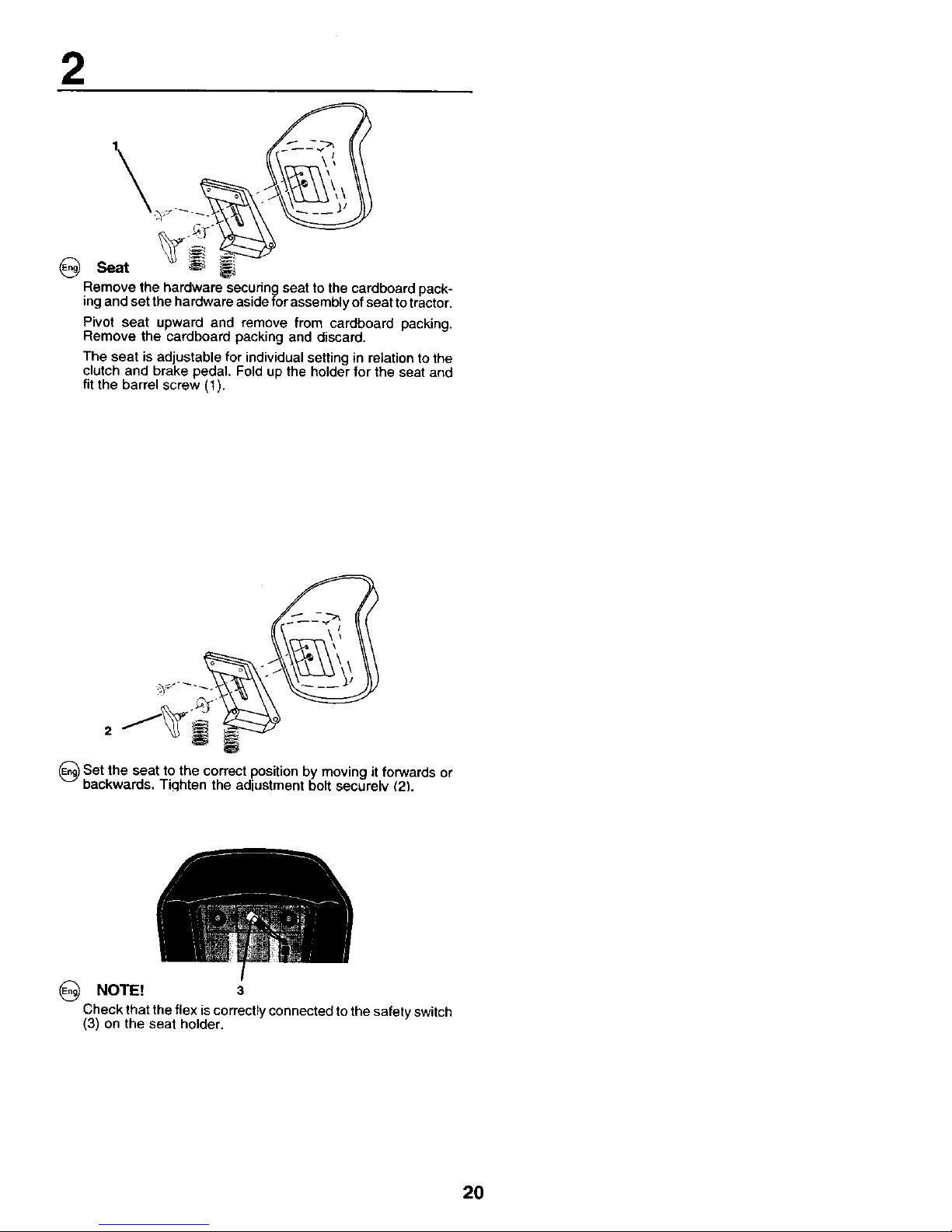
@
Remove the hardware securing seat to the cardboard pack-
ing and set the hardwara aside for assembly of seat to tractor.
Pivot seat upward and remove from cardboard packing.
Remove the cardboard packing and discard.
The seat is adjustable for individual setting in relation to the
clutch and brake pedal, Fold up the holder for the seat and
fit the barrel screw (t).
2
_)Set the to the correct it forwards
seat
position by moving
or
backwards, Tiqhten the adiustment bolt securelv _2_.
(_ NOTE! 3
Check that the flex is correctly connected to the safety switch
(3) on the seat holder.
20
Page 10
O
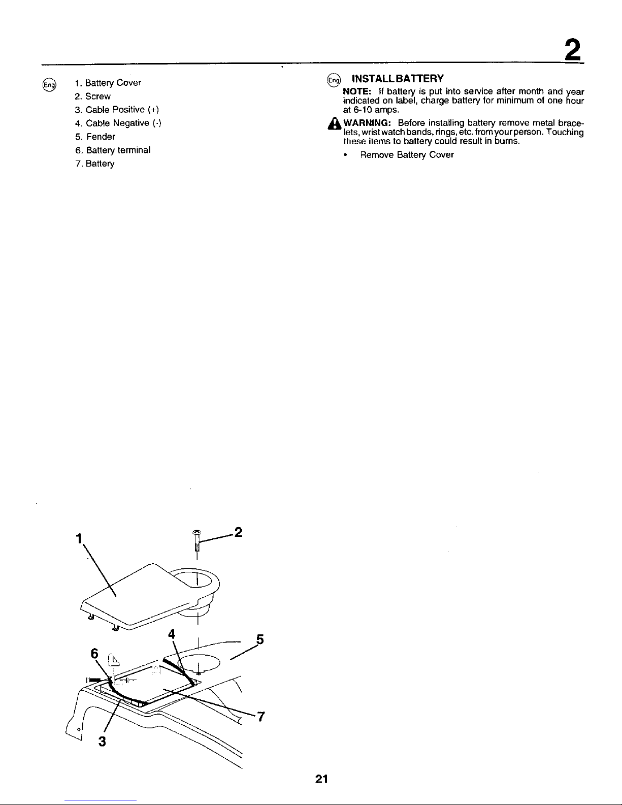
1. Battery Cover
2. Screw
3. Cable Positive (+)
4. Cable Negative (-)
5. Fender
6. Battery terminal
7. Battery
2
(_) INSTALL BATTERY
NOTE: If battery is put into service after month and year
indicated on label, charge battery for minimum of one hour
at 6-10 amps.
_q_,WARNING: Before installing battery remove metal brace-
lets,wristwatch bands, dngs, etc.from yourperson. Touching
these items to battery could result in burns.
Remove Battery Cover
1
4
0 F'
3
21
Page 11
2
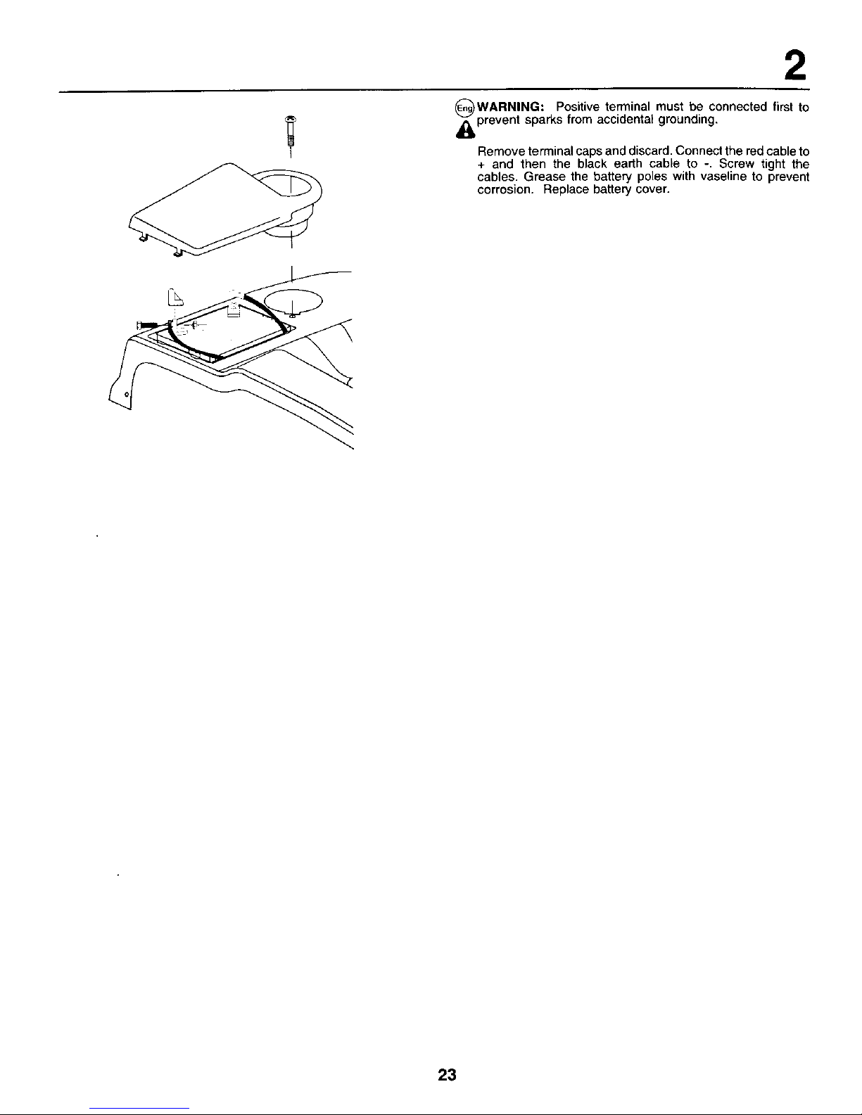
OWARNING: Positive terminal must be connected first to
_prevent sparks from accidental grounding.
Remove terminal caps and discard, Connect the red cable to
+ and then the black earth cable to -, Screw tight the
cables. Grease the battery poles with vaseline to prevent
corrosion. Replace battery cover.
23
Page 12
2
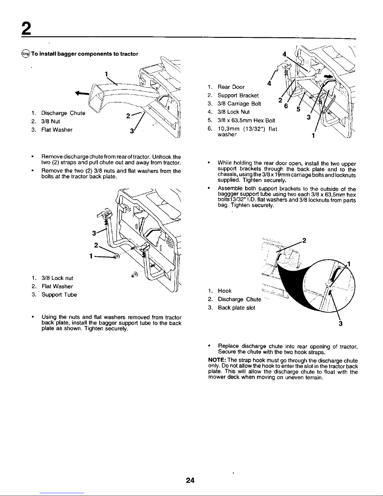
O To install bagger components to tractor
1
1. Discharge Chute
2. 3/8 Nut
3. Flat Washer
4
1. Rear Door
2. Support Bracket
2
3. 3/8 Carriage Bolt 6
4. 3/8 Lock Nut
5. 3!8 x 63,5mm Hex Bolt 3
6. 10,3mm (13/32") flat
washer 1
Remove discharge chute from rear oftractor. Unhook the
two (2) straps and pull chute out and away from tractor.
Remove the two (2) 3/8 nuts and flat washers from the
bolts at the tractor back plate.
1. 3/8 Lock nut
2. Flat Washer
3. Support Tube
31
2_
Using the nuts and flat washers removed from tractor
back plate, install the bagger support tube to the back
plate as shown. Tighten securely.
While holding the rear door open, install the two upper
support brackets through the back plate and to the
chassis, using the 3/8 x 19mm carriage bolts and Iocknuts
supplied. Tighten securely.
Assemble both support brackets to the outside of the
baggger support tube using two each 3/8 x 63,5mm hex
bolts13/32" I.D. flat washers and 3/8 Iocknuts from parts
bag. Tighten securely.
1. Hook
2. Discharge Chute -
3. Back plate slot
3
Replace discharge chute into rear opening of tractor.
Secure the chute with the two hook straps.
NOTE: The strap hook must go through the discharge chute
only. Do not allow the hook to enter the slot in the tractor back
plate. This will allow the discharge chute to float with the
mower deck when moving on uneven terrain.
24
Page 13
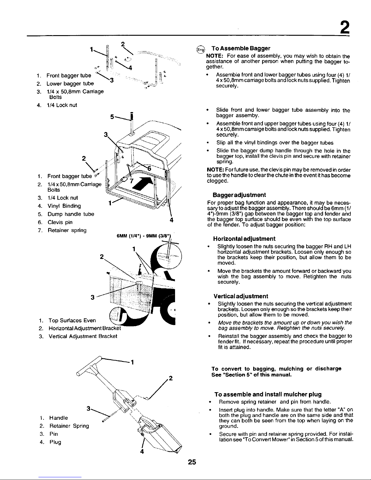
1. Front bagger tube _3
2. Lower bagger tube
3. 1/4 x 50,8mm Carriage
Bolts
4. 1/4 Lock nut
3\
2
1,
2. 1/4x 50,8mm Carriage
Bolts
3. 1/4 Lock nut
4. Vinyl Binding
5. Dump handle tube
6. Clevis pin
7. Retainer spring
3
1
1. Top Surfaces Even
2.
3. Vertical Adjustment Bracket
6MM
2
3
t. Handle
2. Retainer Spring
3. Pin
4. Plug
2
To Assemble Bagger
NOTE: For ease of assembly, you may wish to obtain the
assistance of another person when putting the bagger to-
gether.
Assemble front and lower bagger tubes using four (4) 1/
4 x 50,8ram carriage boltsand lock nutssupplied. Tighten
securely.
• Slide front and lower bagger tube assembly into the
bagger assemby.
Assemble front and upper bagger tubes using four (4) 1/
4x 50,8mm carraige bolts and lock nutssupplied. Tighten
securely.
Slip all the vinyl bindings over the bagger tubes
Slide the bagger dump handle through the hole in the
bagger top, install the clevis pin and secure with retainer
spring.
NOTE= For future use, the clevis pin may be removed in order
to use the handle to clear the chute in the event ithas become
clogged.
Bagger adjustment
For proper bag function and appearance, it may be neces-
sary to adjust the bagger assembly. There should be 6mm (1/
4")-9mm (3/8") gap between the bagger top and fender and
the bagger top surface should be even with the top surface
of the fender. To adjust bagger position:
Horizontal adjustment
Slightly loosen the nuts securing the bagger RH and LH
hodzontal adjustment brackets. Loosen only enough so
the brackets keep their position, but allow them to be
moved.
Move the brackets the amount forward or backward you
wish the bag assembly to move. Retighten the nuts
securely.
Vertical adjustment
Slightly loosen the nuts securing the vertical adjustment
brackets. Loosen only enough so the brackets keep their
position, but allow them to be moved.
Move the brackets the amount up or down you wish the
bag assembly to move. Retighten the nuts securely.
Reinstall the bagger assembly and check the bagger to
fender fit. If necessary, repeat the procedure until proper
fit is attained.
To convert to bagging, mulching or discharge
See "Section 5" of this manual.
4
25
To assemble and install mulcher plug
Remove spring retainer and pin from handle.
Insert plug into handle. Make sure that the letter "A" on
both the plug and handle are on the same side and that
they can both be seen from the top when laying on the
ground.
Secure with pin and retainer spring provided. For instal-
lation see "To Convert Mower" in Section 5 of this manual.
Page 14
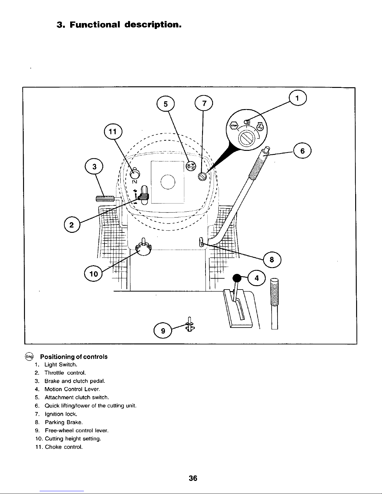
3. Functional description.
i
Positioning of controls
1. Light Switch.
2. Throttle control.
3. Brake and clutch pedal,
4, Motion Control Lever.
5, Attachment clutch switch.
6. Quick lifting/lower of the cutting unit.
7. ignition lock.
8. Parking Brake.
9, Free-wheel control lever.
10. Cutting height setting,
11, Choke control,
36
Page 15
3
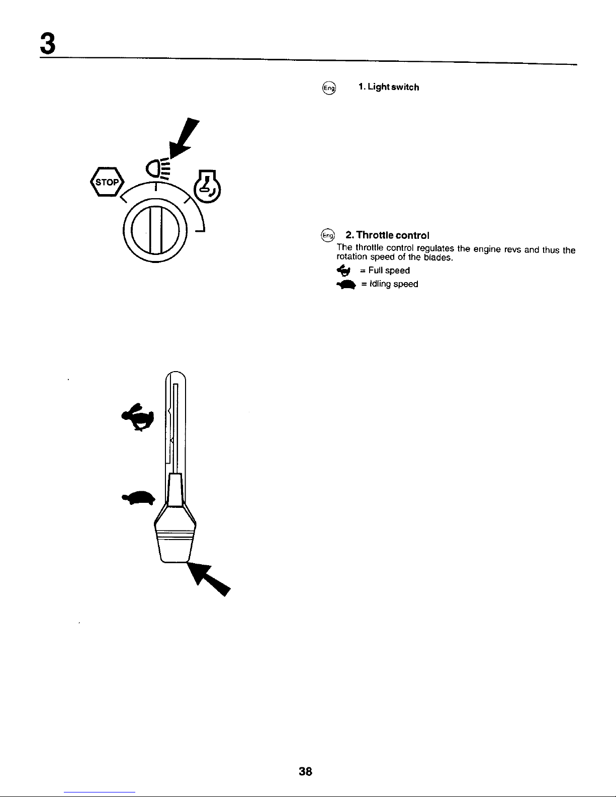
1. Light switch
2. Throttle control
The throttle control regulates the engine revs and thus the
rotation speed of the blades.
_1 = Full speed
= Idling speed
38
Page 16

_) 3. Brake and clutch pedal
When the pedal ispushed down the brake is appFiedand the
motor"is disengaged,
39
Page 17

3
S
N
(_ 4. Motion control lever
There are four different positions for this lever:
N = Neutral (no d_ve)
S = Slow
F = Fast
R = Reverse
The lever can be moved steplessly between S and F to ensure
the required speed.
4O
Page 18

3
(_ 5. Attachment clutch switch
2
6. Quick lifting/lowering of the cutting unit
Pull the lever backwards to quickly liftthe cutting unit when
passing over irregularities inthe lawn, etc. During transporta-
tion the cutting unit shall be in the highest position. Pull the
lever back until it locks. To lower the unit: Pull the lever
backwards ( 1). Push inthe button (2) and then move the lever
forwards (3).
41
Page 19

3
OFF ON START
{_ 7. Ignition Lock
There are three different positions for the ignition key:
OFF All electric current broken.
ON Electdc current connected.
START Start motor connected.
WARNING!
Never leave the key in the ignition lock when leaving the
machine on its own.
(_) 8. Parking brake
Connect the parking brake in the following way:
1. Press down the brake pedal to bottom position.
2. Move the parking brake lever upwards and hold in this
position.
3. Release the brake pedal.
To release the parking brake all that is necessary is to push
down the brake pedal.
42
Page 20

3
(_ 9. Free-wheel Control Lever
To tow or move the tractor without the aid of the engine, the
free-wheel control knob must be pulled out and locked in
position.
43
Page 21

3
(_ 10. Cutting height setting
The required cutting height isset with the aid of thewheel. Tile
cutting height is increased when it is turned clockwise. The
wheel is easier to turn if the lever for lifting/lowering of the
cutting unit is pulled backwards at the same time.
(_ 11.Chokecontrol
When the engine is cold the choke should be purled out
before starting, When the engine has started and is running
smoothly push the choke in.
44
Page 22

4. Before starting.
(_ Filling up
The engine should be run of pure (not oil mixed) unleaded
petrel, Do not fillbeyond the lower edge of the filling hole. De
not fill over max level,
WARNING!
Petrel is highlyinflammable, Proceed with care and fill up with
petrol outdoors. Do not smoke when filling with petrol or fill up
when the engine is warm, Do not overfill the tank since the
pertrel can expand and overflow. Make sure that the petrol cap
is securely tightened after filling. Store petrol in a cool place
in an appropriate container for engine fuel, Check the petrol
tank and pipes,
45
Page 23

4
(_ Oil level
The combined oil refilling cap and the oil stick is accessible
when the bonnet is lifted forwards. The oil level in the engine
should be checked before each run. Make sure that the tractor
is horizontal. Unscrew the oil stick and wipe clean. Replace
the oi_stick and screw tight. Remove again and check the level
_The oil level should lie between the two the oil
markings
on
stick. If more oil is needed add SAE 30 oil to the "FULL"
marking. SAE 5W-30 oil should be used during the winter
(below freezing point),
+'-FULLCAUTION - DO
46
Page 24

4
G
Tire air pressure
Check the tyre pressure regularly. The pressure in the front
tyres should be 1 bar (14 PSI) and 0.8 bar (12 PSI) in the back
tyres.
47
Page 25

5. Driving.
_J
Starting of motor
Make sure that the cutting unit is in the transport position (top
position) and that the lever for connection/disconnection ofthe
cutting unit is in the disconnection position.
(_) Press down the clutch/brake pedal completely and hold down.
Make sure that the motion control lever is in neutral "N".
(_ Pull out the choke control (if engine is cold).
48
Page 26

G Warm motor: Push the gas control half-way to full gass
position ",_y".
5
O Turn the ignition key to "START position".
NOTE?
Do not runthe start motor more than 5 seconds at once. If the
engine will not start, wait about 10 seconds before the next
try.
(_ Let the ignition key return to the "ON" position when the
engine has started and push in the choke control as soon as
the engine is running smoothly. Push the gas control to the
required speed. For cutting: full gas.
49
Page 27

5
IMPORTANT! COLD STARTING FOR HYDRO
IMPORTANT: COLD STARTING FOR HYDRO (BELOW
40°F[4°C]) - AFTER STARTING ENGINE AND BEFORE
"DRIVING, LET TRANSMISSION WARM UP FOR ONE (1)
MINUTE BY PLACING MOTION CONTROL LEVER IN NEU
TRAL (N) POSITION AND RELEASING CLUTCH/BRAKE
PEDAL.
PURGETRANSMISSION
To ensure proper operation and performance, it is recom
mended that the transmission be purged before operating
tractor for the first time. This procedure will remove any
trapped air inside the transmission which may have devel-
oped during shipping of your tractor.
IMPORTANT: SHOULD YOUR TRANSMISSION REQUIRE
REMOVAL FOR SERVICE OR REPLACEMENT, IT SHOULD
BE PURGED AFTER REIN STALLATION BEFORE OPER-
ATING THE TRACTOR.
Park tractor on level surface so it will not roll in any
direction. Parking brake must be disengaged for the
following procedure,
Disengage transmission by placing freewheel control in
freewheeling position.
5O
Page 28

5
G
NOTE{
The machine is equipped with a safety switch which
immediatelybreaksthe currenttothe engine ifthedriver
leavestheseatwithenginerunningand withtheconnection/
disconnection lever in position "connection".Your
machine is also equiped with a system that win not allow
mower to operate if the bagger or optional rear discharge
deflector is not installed properly.
(_ Driving
Lower the cutting unit by moving the lever forwards. Release
the brake/clutch pedal slowly. Connect the cutting unit and
move the motion control lever to the requireposition. Choose
a driving speed which suits the terrain and required cutting
results.
52
Page 29

@
Cutting tips
Clear the lawn from stones and other objects which can be
thrown away by the blades.
Localize and mark stones and other fixed objects to
avoid collision.
Begin with a high cutting height and reduce until the
required cutting result is obtained.
The cutting result is best with high engine speed (blades
rotate quickly) and low gear (machine goes slowly). Ifthe
grass is too long and thick the drive speed can be in-
creased by selecting a higher gear or reducing the
motor speed, without affecting the cutting result.
The best lawn isachieved ifthe grass iscut often. Cutting
becomes more even and the cut grass is more evenly
distributed over the surface. Total time taken is not
greater, since higher drive speed can be selected
without affecting the cutting results.
Avoid cutting wet grass. The cutting results will be worse
since the wheels will sink into the soft lawn.
Spray the cutting unit with water underneath after use.
5
53
Page 30

5
i , iI
\
To Dump Bagger
Your tractor isequipped witha Dump Bag Alarm, To turn off the
alarm disengage the attachment .clutch switch,
Position tractor in location you wish to dump bagger.
Place motion control lever in Neutral position and set
parking brake,
Raise dump handle to its highest position. Pull handle
forward to raise bagger and dump clippings.
To continue mowing, be sure bagger is down and in proper
operating position which will allow mower to operate.
54
Page 31

To convert
mower
Converting to mulching or rear discharging will require the
purchase of these accessories.)
To mulching
Place deck into the high cut position.
Remove bagger or optional rear discharge deflector.
Unhook the two (2) straps and remove discharge chute
Insert plug and handle assembly through back plate
and onto the mower deck chute adaptor.
Retain the plug assembly by connecting the two straps
over the handle and hook into the holes provided.
Replace bagger or optional rear discharge deflector to
allow mower to operate.
You are new ready to begin mulching.
To rear discharging
Place deck into the high cut position,
Remove bagger and mulching plug (if installed).
Install discharge chute through opening in backplate and
slide over deck adaptor.
Attach the chute by hooking the two straps intothe holes
in the flange of the chute.
Install the discharge deflector to the backplate by screwing
the four (4) wing screws into the threaded inserts located
in the backplate.
Tighten the wing screws securely.
Tobagging
Place deck into the high cut position.
Remove the rear discharge deflector or mulching plug.
Insert thedischarge chuteintothe opening inthebackplate
and onto the mower deck adaptor.
Attach the chute to the tractor by hooking the two straps to
the flange of the chute.
Install bagger into tractor.
5
55
Page 32

5
J
f
@
WARNING!
Do not drive in terrain at an angle of mere than max. 10°,
The risk for spark-ever backwards is large,
In steep terrain the risk fer tipping is considerable,
Avoid stopping and starting in sloping terrain.
Only change gear when the machine is standing still to
avoid damaging the gear box,
57
Page 33

5
(_Use the left side of the machine to cut close to trees, bushes
and paths, etc. The blade cuts about 15 mm inside the edge
of the cover.
Switching off the engine
Move the gas control to "gh".
Disconnect the cutting unitby moving the connect/discon-nect
lever downwards.
Lift up the cutting unit and turn the ignition key to "OFF"
position.
Allow the engine to idle for 1-2 minutes to cool down before
switching off after a hard work.
58
Page 34

5
(_ " WARNING!
Do not fleave the ignition key inthe machine when notin use
to prevent children and other aunauthodzed persons start-
ing the engine.
59
Page 35

6. Maintenance, adjustment.
@
WARNING!
Before servicing the engine or cutting unit the following shall
be carried out:
Press down the clutch/brake pedal and engage the
parking brake lever,
Put gear lever in neutral.
Move connection/disconnection lever to disengaged
position,
Switch off engine.
Remove the ignition cable from the plug.
(_ (1)
(2)
Hood
Headlight wire connector
G
Engine hood
Raise hood.
Unsnap headlight wire connector,
Stand infront of tractor. Grasp hood at sides, tilt forward
and liftoff of tractor.
To reinstall, slide hood pivot brackets into slots in frame.
Reconnect headlight wire connector and close hood.
6O
Page 36

6
(_ SERVICE RECORD
FILL IN DATES AS YOU COMPLETE REGULAR SERVICE
Even!
200 hours
As Every 8 Every Every Every
Needed hours 25 hours 50 hours 100 hours
Change engine oil ........................................................................... •
Lubricate pivot points ....................................................................... •
Check brake operation .............................. •
Clean air screen ........................................................... •
Clean air filter and pre-cleaner ....'............................... •
Replace air cleaner paper cartridge ........................................................................................ •
Clean engine cooling fins ................................................................................... •
Replace spark plug ........................................................................................................... •
Check tire pressure ..................................
Replace fuel filter ....................................................................................................................................... •
Clean ba_e,'y and terminals ............................................................ •
Check muffler .....................................................................................................
Lubricate ball joints ................................................................................................................ •
Toe-in adjustment .................................... •
Carburetor adjustment ............................. •
62
Page 37

Blades
The blades should be sharp to achieve best cutting results.
Sharpening can be carried out with a file or grinding disc.
NOTE!
It is very important that both blades are sharpened equally to
avoid imbalance.
6
1, 2,
_5-Star blade w! _6-Star blade w/left
pattern pattern
right hand threaded bolt "_" hand threaded bolt
(_ Blade Care
Important: The blades on your mower are not the same and
must be installed on the correct side, It is suggested that you
work on one blade at a time to ensure proper assembly of
components.
65
Page 38

6
8
J\
(_ t, HexboRdghthandthreaded. 5. 5StarCenterHole
2. LockWasher 6. 5 Star Pattern
3. FlatWasher 7. TrailthgEdge
(_ 5 Star pattern blade
The center ofthis blade has a five (5) star pattem. The bolt that
attaches this blade has normal Right Hand threads that
loosens by turning (_ ,) counter-clockwise and tightens by
turning (,_) clockwise.
4. Blade S. Mancb-elAssembly
8
6
6 Star pattern blade
The center of this blade has a 6star pattern. The bolt attaching
this blade has Left Hand threads that loosens by tuming (_)
clockwise and tighten by turning (w,) counterclockwise,
(_1. Hex bolt left hand threaded,
2, Lock Washer
3, Flat Washer
4. Blade
5. 6 Star Center Hole
6. 6 Star Pattern
7. Trailing Edge
8, Mandrel Assembly
66
Page 39

6
Brakes
The brakes are located inside the right rear wheel The wheel
should be dismantled for best access,
1. Press down the clutch/brake pedal and engage the park-
ing brake.
_)1. Measure the distance between the brake lever and the
adjuster nut.
2. The distance should be 40 mm (1.56").
3. Adjust the distance if necessary by first loosening the
lock nut (2) and then adjusting with the nut (1).
WARNING!
Do not forget to tighten the lock nut after completing adjust-
ment.
69
Page 40

6
Dismantling of the cutting unit
Work from the right side of the machine.
1. Take off the belt from the engine pulley (1).
2. Remove the two rear retainer springs (2) and knock offthe
axle taps with a hammer.
7O
Page 41

6
(_ 3. Remove the retainer springs (3), (4), (5) and axles.
4. Pull the lever for lifting/lowering the cutting unit back-
wards.
5. Pull out the cutting unit from the machine.
(_ Assemblyofthecutting unit
Assemble in the reverse order to dismantling.
• Push in the cutting unit under the machine.
71
Page 42

6
Replacement of drive belt for cutting unit
1. Dismantle the cutting unit as described previousley,
2. Work offthe belt fromthe unit'sleftpulleyand then from the
other wheels.
3. Pull the belt away from the cutting unit.
4. The new belt is mounted in the reverse order. Check that
the belt lies inside all the belt guides.
72
Page 43

6
Adjustment of the cutting unit
A. In the direction of travel
1. Check that the air pressure is correct in all four tyres,
2. Make sure that the machine is on a horizontal surface.
3. Lift up the cutting unit to its highest position.
4. Measure the distances A and B.
_To achieve best results the unit's front
cutting cutting
edge (a)
should be about 10 mm (0.375") lower than the back edge
(A). Adjust in the following way to raise the back edge:
1. Loosen the nut (1) on both the left and right levers.
2. Screw the nut (2) the same number ofturn s on both levers.
3. When the correct distance (A) is obtained this setting is
locked with the nut (1).
73
Page 44

6
(_ (1) Bottom edge of mower
(2) Lift link adjustment nut
O
SIDE-TO-SIDE ADJ USTMENT
Raise mower to highest position.
Atthe midpoint of both sides of mower, measure height
from bottom edge of mower to ground. Distance "A" should
be the same or within 6mm (1/4") of each other.
If adjustment is necessary, make adjustment on one side
of mower only.
To raise one side of mower, tighten lift link adjustment nut
on that side.
To lower one side of mower, loosen liftlink adjustment nat
on that side.
NOTE: Three full turns of adjustment nut will change mower
height about 1/8".
Recheck measurements after adjusting.
74
Page 45

6
(_ Replacement of drive belt
1. Dismantle the cutting unit as described previously.
2. Pull apart the contact for the cable to the electrical connec
lion (1).
3. Dismantle the motion restrainer for the clutch (2).
4. Engage the parking brake and work off the belt upwards
from the pulley (3), the clutch pulley (4).
5. Pushthe belt upbetween two fan blades and rotate the fan
clockwise until the belt comes loose (5).
6. Take off the belt from the engine pulley.
75
Page 46

6
(_1. Motion Control Lever
2. Neutral Lock Gate
3. Adjustment Bolt
(_ TRANSAXLE MOTION CONTROL LEVER NEU-
TRAL ADJUSTMENT
The motion control lever has been preset at the factory and
adjustment should not be necessary,
Loosen adjustment bolt in front of the right rear wheel, and
lightly tighten.
Stad engine and move motion control lever until tractor
does not move forward or backward.
Hold motion control lever in that position and turn engine
off.
While holding motion control lever in place, loosen the
adjustment bolt.
Move motion control lever to the neutral (N) (lock gate)
position.
Tighten adjustment bolt securely.
NOTE: If additional clearance is needed to get to adjustment
bolt, move mower deck height to the lowest position. After
above adjustment is made, if the tractor still creeps forward or
backward while motion control lever is in neutral position,
follow these steps:
Loosen the adjustment bolt.
Move the motion control lever 1/4 to 1/2 inch in the direction
it is trying to creep.
Tighten adjustment bolt securely.
Start engine and test.
If tractor still creeps, repeat above steps until satisfied.
76
Page 47

6
(_ TRANSAXLE COOLING
The fan and cooling fins of transmission should be kept clean
to assure proper cooling.
Do not attempt to clean fan or transmission while engine is
running or while the transmission is hot.
Inspect cooling fan to be sure fan blades are intact and
clean.
Inspect cooling fins for did, grass clippings and other
materials,
TRANSAXLE PUMP FLUID
The transaxle was sealed at the factory and fluid mainte
nance is not required. Should the transaxle ever leak or
require servicing, contact your nearest authorized service
center/department.
78
Page 48

7. Troubleshooting.
(_ Engine will not start
1. No fuel in fuel tank.
2. Plug defective.
3. Plug connection defective.
4. Dirt in carburettor or fuel pipe.
Start motor will not turn engine
1. Battery flat.
2. Poor contact between cable and battery pole.
3. Connection/disconnection level in wrong position.
4. Main fuse defective.
5. Ignition lock defective.
6. Safety contact for clutch/brake pedal defective.
7. Clutch/brake pedal not pushed down.
Engine runs unevenly
1. Gear too high.
2. Plug defective.
3. Carburettor incorrectly set.
4. Air filter blocked.
5. Fuel tank ventilation blocked.
6. Ignition setting defective.
7. Dirt in fuel pipe.
Engine feels weak
1. Air filter blocked.
2. Plug defective.
3. Dirt in carburettor or fuel pipe.
4. Carbureffor incorrectly set.
Engine overheats
1. Engine overloaded.
2. Air inlet or cooling fins blocked.
3. Fan damaged.
4. Too little or no oil in engine.
5. Ignition setting defective.
6. Plug defective.
Battery does not charge
f. Fuse defective.
2. One or several cells defective.
3. Poor contact between battery poles and cables.
Lighting does not function
f. Bulbs defective.
2. Switch defective.
3. Short-circuit in cable.
The machine vibrates
1. Blades loose.
2. Engine loose.
3. Unbalance in one or both blades resulting from damage
or poor balancing after sharpening.
Uneven cutting results
1, Blades blunt.
2. Cutting unit skew.
3. Long or wet grass.
4. Grass stuck under cover.
5. Different air pressures in tyres on left and right side.
6. Gear too high.
7. Drive belt slipping.
79
Page 49

8. Storage.
O The following steps should be taken when mowing season
is over:
Clean the entire machine, especially underneath the
cutting unit cover.
Touch up all chipped paint surfaces in order to avoid
corrosion.
Change engine oil.
Drain the fuel tank. Start the engine and allow it to run until
it is out of fuel.
Remove the spark plug and pour one table spoon of
engine eit into the cylinder. Pu_lthe engine over in order
to distribute the oil. Return the spark plug.
Remove the battery. Recharge and store it in a cool, dry
place. Protect the battery from low temperatures.
The machine should be stored indoors in a dry, dust-free
place.
WARNING!
Never use gasoline when cleaning. Use degreasing deter
gent and warm water instead.
Service
When ordering, we need the following information:
Date of purchase, model, type and serial number of the
mower, Always use odginal spare parts. Contact your local
dea_er of distributor for warranty service and repairs.
82
Page 50

173743 1.13.00 RD Printed in U.S.A.
 Loading...