

Page 1
[ROFTXMAN°
25908
0
Instruction manual
Please read these instructions
carefully and make sure you
understand them before using this
machine.
Page 2

1
Safety specifications.
Sicherheitsbestimmungen.
Consignes de securitS.
Assembly.
Zusammenbau.
Montage.
3
Functional description.
Funktionsbeschreibung.
Description du fonctionnement.-
4
Procedure before start.
MaBnahmen vor dem Anlassen.
Avant de demarrer.
Driving.
Betrieb.
Conduite.
6
7
8
Maintenance, adjustment.
Instandhaltung, Einstellung.
Entretien, r_glages.
Fault tracing.
Stbrungssuche.
Recherche des pannes.
Storage.
Aufbewahrung.
Rangement.
We reserve the right to changes without prior notice.
Anderungen ohne vorherige Mitteilung sind vorbehalten,
Nou$ nous reservons le droit d'apporter des modifications sans avis prealable.
Nos reservamos el derecho a introducir modificaciones sin previo aviso.
Ci riserviamo il didtto di modifiche o cambiamenti senza preawiso.
Wii houden ons bet recht voor om veranderingen aan te brengen zonder voorafgaande mededeling.
2
Page 3
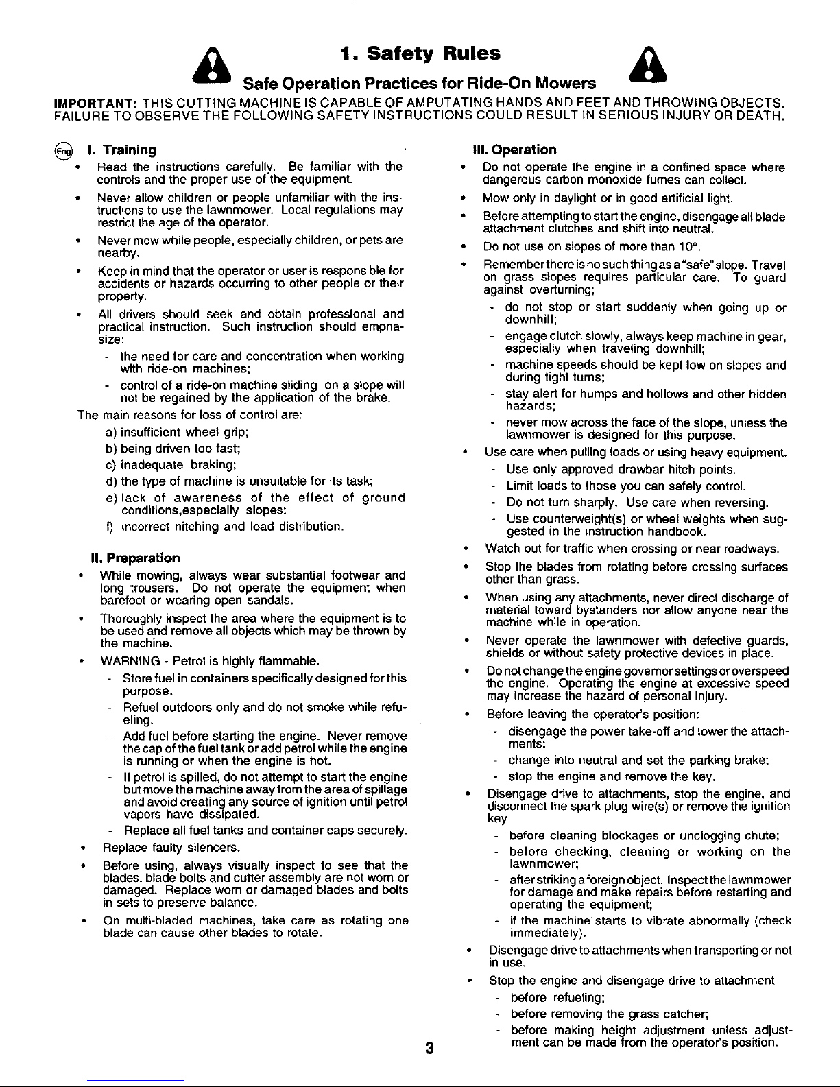
1. Safety Rules &
Safe Operation Practices for Ride-On Mowers
IMPORTANT: THIS CUTTING MACHINE IS CAPABLE OF AMPUTATING HANDS AND FEET AND THROWING OBJECTS.
FAILURE TO OBSERVE THE FOLLOWING SAFETY INSTRUCTIONS COULD RESULT iN SERIOUS INJURY OR DEATH.
@
I. Training
Read the instructions carefully. Be familiar with the
controls and the proper use of the equipment.
Never allow children or people unfamiliar with the ins-
tructions to use the lawnmower. Local regulations may
restrict the age of the operator.
Never mow while people, especially children, or pets are
nearby.
Keep in mind that the operator or user is responsible for
accidents or hazards occurring to other people or their
property.
All ddvers should seek and obtain professional and
practical instruction. Such instruction should empha-
size:
- the need for care and concentration when working
with ride-on machines;
- control of a ride-on machine sliding on a slope will
not be regained by the application of the brake.
The main reasons for loss of control are:
a) insufficient wheel gdp;
b) being driven too fast;
c) inadequate braking;
d) the type of machine is unsuitable for its task;
e) lack of awareness of the effect of ground
conditions,especially slopes;
f) incorrect hitching and load distribution.
II. Preparation
While mowing, always wear substantial footwear and
long trousers. Do not operate the equipment when
barefoot or weadng open sandals.
Thoroughly inspect the area where the equipment is to
be used and remove all objects which may be thrown by
the machine.
WARNING - Petrol is highly flammable.
- Store fuel in containers specifically designed for this
purpose.
Refuel outdoors only and do not smoke while refu-
eling.
- Add fuel before starting the engine. Never remove
the cap of the fuel tank or add petrol while the engine
is running or when the engine is hot.
If petrol is spilled, do not attempt to start the engine
but move the machine away from the area of spillage
and avoid creating any source of ignition until petrol
vapors have dissipated.
Replace all fuel tanks and container caps securely.
Replace faulty silencers.
Before using, always visually inspect to see that the
blades, blade bolts and cutter assembly are not worn or
damaged. Replace worn or damaged blades and bolts
in sets to preserve balance.
On multi-bladed machines, take care as rotating one
blade can cause other blades to rotate.
3
III. Operation
Do not operate the engine in a confined space where
dangerous carbon monoxide fumes can collect.
Mow only in daylight or in good artificial light.
Before attempting to start the engine, disengage allblade
attachment clutches and shift into neutral.
Do not use on slopes of more than 10°.
Remember there isno such thing as a"safe" slope. Travel
on grass slopes requires particular care. To guard
against overturning;
- do not stop or start suddenly when going up or
downhill;
- engage clutch slowly, always keep machine in gear,
especially when traveling downhill;
- machine speeds should be kept low on slopes and
during tight turns;
- stay alert for humps and hollows and other hidden
hazards;
- never mow across the face of the slope, unless the
lawnmower is designed for this purpose.
Use care when pulling loads or using heavy equipment.
Use only approved drawbar hitch points.
Limit loads to those you can safely control.
Do not turn sharply. Use care when reversing.
Use counterweight(s) or wheel weights when sug-
gested in the instruction handbook.
Watch out for traffic when crossing or near roadways.
Stop the blades from rotating before crossing surfaces
other than grass.
When using any attachments, never direct discharge of
material toward bystanders nor atlow anyone near the
machine while in operation.
Never operate the lawnmower with defective guards,
shields or without safety protective devices in place.
Do not change the engine govemor settingsoroverspeed
the engine. Operating the engine at excessive speed
may increase the hazard of personal injury.
Before leaving the operator's position:
- disengage the power take-off and lower the attach-
ments;
- change into neutral and set the parking brake;
- stop the engine and remove the key.
Disengage drive to attachments, stop the engine, and
disconnect the spark plug wire(s) or remove the ignition
key
- before cleaning blockages or unclogging chute;
- before checking, cleaning or working on the
lawnmower;
- afferstriking aforeign object. Inspectthelawnmower
for damage and make repairs before restarting and
operating the equipment;
if the machine starts to vibrate abnormally (check
immediately).
Disengage drive to attachments when transporting or not
in use,
Stop the engine and disengage drive to attachment
before refueling;
before removing the grass catcher;
- before making height adjustment unless adjust-
ment can be made frem the operator's position.
Page 4
&
Reduce the throttle setting during engine run-out and,
ifthe engine isprovided with ashut-off valve,turn the fuel
off at the conclusion of mowing.
IV. Maintenance and Storage
Keep all nuts, bolts and screws tight to be sure the
equipment is in safe working condition.
Never store the equipment with petrol in the tank inside
a building where fumes may reach an open flame or
spark.
Allow the engine to cool before stodng inany enclosure.
To reduce the fire hazard, keep the engine, silencer,
battery compartment and petrol storage area free of
grass, leaves, or excessive grease.
Check the grass catcher frequently for wear or deterio-
ration.
Replace worn or damaged parts for safety.
If the fuel tank has to be drained, this should be done
outdoors.
On multi-b_aded machines, take care as rotating one
blade can cause other blades to rotate.
When machine isto be parked, stored or left unattended,
lower the cutting means unless a positive mechanical
lock is used.
CAUTION: Always disconnect spark plug wire and
place wire where it cannot contact spark plug in
order to prevent accidental starting when setting
up, transporting, adjusting or making repairs.
4
Page 5

(_ These symbols may appear on your machine or in the literature supplied with the product. Learn and understand their meaning.
R N H L (]
REVERSE NEUTRAL HIGH LOW FAST SLOW LIGHTS ON UGHTS OFF
RUCKWARTSGANG LEERLAUF HOCH NIEDRIG SCHNELL LANGSAM LICHT AN UCHT AUS
MARCHE ARRII:RE POINT MORT HAUT BAE RAPIDE LENTE PHARES ALLUMI=S FHARES _TEINTS
ACHTERUIT VRIJLOOP HOOG LAAG SNEL LANGZAAM UCHTEN AAN LICHTEN UIT
REVES NEUTRO ALTO BAJO RAPIDO LENTO LUCES ENCENDIDAS LUCES AFAGAOAS
RETROMARCIA FOLLE AUMENTARE DIMINUIRE VELOCE LENTO LUCI ACCESE LUCI SPENTE
ENGINE ON ENGINE OFF
MOTOR LAUFT MOTOR AUS
MOTEUR EN MARCHE MOTEUR ARRIETE
MOTOR AAN MOTOR UIT
MOTOR ENCENDIDO MOTOR APAGADO
MOTORE ACCESO MOTORE SPENTO
PARIGNGBRAKELOCKED
FESTSTELLBREMSE VERRIEGELT
FREIN DE PARKING VERROUILLE
PARKEERREM GEBLOKKEERD
FRENODE ESTACIONAMIENTO
CERRADO
FRENO _ PARCHEGGIOINNESTATO
UNLOCKED PARKING BRAKE BATTERY
ENTRIEGELT FESTSTELLBREMSE BATTERIE
OEVERROUILU_ FREIN DE PARKING BATTERIE
GEDEBLOKKEERD FRENO DE ESTACIONAMIENTO ACCU
ABIERTO FRENO DI PARCHEGGIO BATERiA
DISINNESTATO BATrERIA
CLUTCH CHOKE FUEL OIL PRESSURE DIFFERENTIAL LOCK REVERSE
KUPPLUNG STARTKLAPPE KRAFTSTOFF _LDRUCK DIFFERENTIALSPERRE ROCKWARTSGANG
EMBRAYAGE STARTER CARBURANT PRESSION D'HUILE BLOCAGE DE DIFFERENT[EL MARCHE ARRII=RE
KOPPELING CHOKE BRANDSTOF OUEDRUK DIFFERENTIEELBLOKKERING , ACHTERUIT
EMBRAGUE ESTRANGULACI_N COMBUSTIBLE PRESION DEL ACEITE CERRAOURA DEL OIFERENCIAL MARCHA AL REVES
FRIZIONE STARTER CARBURANTE PRESSIONE DELL'OUO BLOCCAGGIO DIFFERENZIALE RETROMARCIA
I
FORWARD
VORWARTSGANG
MARCHE AVANT
VOORUIT
MARCRA HACIA
OELANTE
MARCIA
IGNITION
ZUNDUNG
ALLUMAGE
ONTSTEKING
IGNICI6N
AWIAMENTO
AI-rACHMENT A_'rACHMENT
CLUTCH ENGAGED CLUTCH DISENGAGED
ANBAUGER_,TE-KUPPLUNG ANBAUGERATE-KUPPLUNG
EINGEKUPPELT AUSGEKUPPELT
LAMES EMBRAYEES LAMES DEBRAYEES
KOPPELING HULPSTUK KOPPELING HULPSTUK
INGESCHAKELD DITGESCHAKELD
EMSRAGUE DEL ACCESORIO EMBRAGUE DEL ACCESORIO
ENGANCHAOC DESENGANCHDO
FRIZIGNE ACCESSORIE FRIZIONE ACCESSORI
INNESTATA DISINNESTATA
CAUTION MOWER HEIGHT BEWARE OF
VORSICHT MAHWERKHOHE THROWN OBJECTS
DANGER HAUTEUR DE COUPE VORSICHT, HOCHGESCHLEUDERT
OPGELET MAAINOOGTE GEGENSTANDE
PRECAUCI6N ALTURA DE LA SEGADORA ATTENTION AUX PROJECTILES
ATTENZIONE ALTEZZA APPARATO LET OP WEGGESUNGERDE
FALCIANTE VOORWERPEN
CUIDADO CON
OBJETOS LANZADOS
AT_ENZlONE AGM OGGETTI
SCAGLIATI
15
Page 6

(_ These symbols may appear on your machine or in the literature supplied with the produst. Learn and understand their meaning.
NO OPERATION
ON SLOPES MORE THAN 10_
NICHT AUF ABH_-NGEN MIT
MEHR ALS 10° STEIGUNG BETREISEN
NE PAS UTILISER SUR OES
PENTES DE PLUS DE 10_
NIET OP HELLINGEN VAN MEER DAN
10° GEBRUtKEN
NO OPERE SOBRE PENBIENTES
DE M,_S DE 10°
NON USASE SU PENDII CON
UN'INCUNAZIONE DI OLTRE 10 _
KEEP BYSTANDERS AWAY READ OWNERS MANUAL
ZUSCHAUER FERNRALTEN SETRIEBSANLEITUNG LESEN
TENIB LEE PASSANTS _, DISTANCE LIRE LE MANUEL
OMSTANDERS UIT DE D'INSTRUCTIONS
BUURT HOUDEN GEERUIKERSHANDLEIOING
GU*_RDESE LEJOS DE GENTE LEZEN
TENERE LONTANI I PASSANTI LEA EL MANUAL DE
IHSTRUCCtOHES
LEGGERE IL MANUALE
DELL'OPERATORE
EUROPEAN MACHINERY WARNING
DIRECTIVE FOR SAFETY WARNUNG
EUROP*_-ISCRE VEflORDNUNG DANGER
FOR MASCRINEN-SICHERHEIT WAARSCHUWING
CONFORME AUX NORMES DE ATENCI_)N
SI_CURIT I_ EUROPI_ENNES AVVERTERZA
VEILIGHEIDC:RICHTLIJN VeeR
EUROPESE MACHtHES
DIRECTIVe OE MAQDINARIA
EUROPEO PARA LA SEGURIDAD
NORMA'flVE AN'nNFORTUNISTICHE
EUROPEE PER MACCHINARI
MOWER L|FT
MAHWERKHUS
RELEVAGE DE L'UNITE OE COUPE
MAAIHOOGTEREGELING
LEVANTAMIENTO DE LA SEGADORA
SOLLEVAMENTO APPARATO FALCIANTE
OANGER, KEEP HA_IOS AND FEET AWAY
GEFAHR, HANDE UND FOSSE FERNHALTEN
DANGER, GARDEZ LES MAINS ET LEe PIEDS AU LOIN
GEVAAR, HANDEN EN VOETEN UIT DE BUURT HOUDEN
PEUGRO, MANTENGA LAS MANES Y LOS PIES LEJOS
PERICOLO. TENERE LONTANI MANI PIEDI
FREE WHEEL
FREILAUF
BOUE UBRE
FREEWHEEL
RUEDA MBRE
COMANDO DISINNESTO
DO NOT OPERATE WITHOUT BAGGER OR DEFLECTOR
NICHT IN BETRIEB NEHMEN OHNE GRASFANGBOX ODER DEFLEKTOR
NE JAMAIS UTILJSER SANS SAC OU DleFLECTEUR.
NONAZIONARE LA MACCHIHA SENSA IL CESTO O SENZO IL DEFLETTORE DI SCARICO
NO PONGA EN MARCHA SIN RECOGEDOR O DEFLECTOR
ZONDER STORTGOOT OF AFWIJKENDE SPATDOEK NIET OPEREREN
16
Page 7

,,CIGARETTES BROLURES GRAVES.
17
Page 8
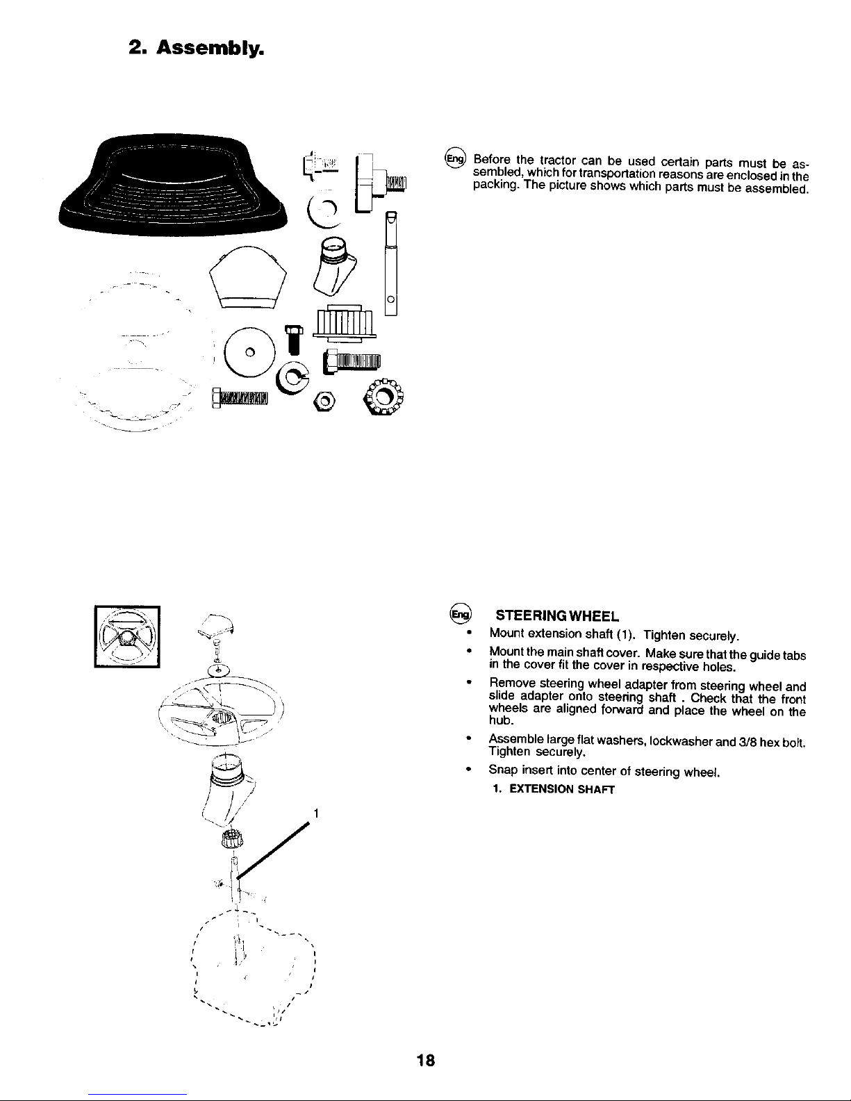
2. Assembly.
_) Before the tractor can be used certain parts must be as-
sembled, which for transportation reasons are enclosed inthe
packing. The picture shows which parts must be assembled.
@
STEERING WHEEL
Mount extension shaft (1). Tighten securely.
Mount the main shaft cover. Make sure thatthe guide tabs
in the cover fit the cover in respective holes.
Remove steering wheel adapter from steering wheel and
slide adapter onto steedng shaft. Check that the front
wheels are aligned forward and place the wheel on the
hub.
Assemble large flat washers, Iockwasher and 3/8 hex bolt.
Tighten securely.
Snap insert into center of steering wheel.
1. EXTENSION SHAFT
I
!/!l
/
I,/
18
Page 9
2
_ i_i ¸
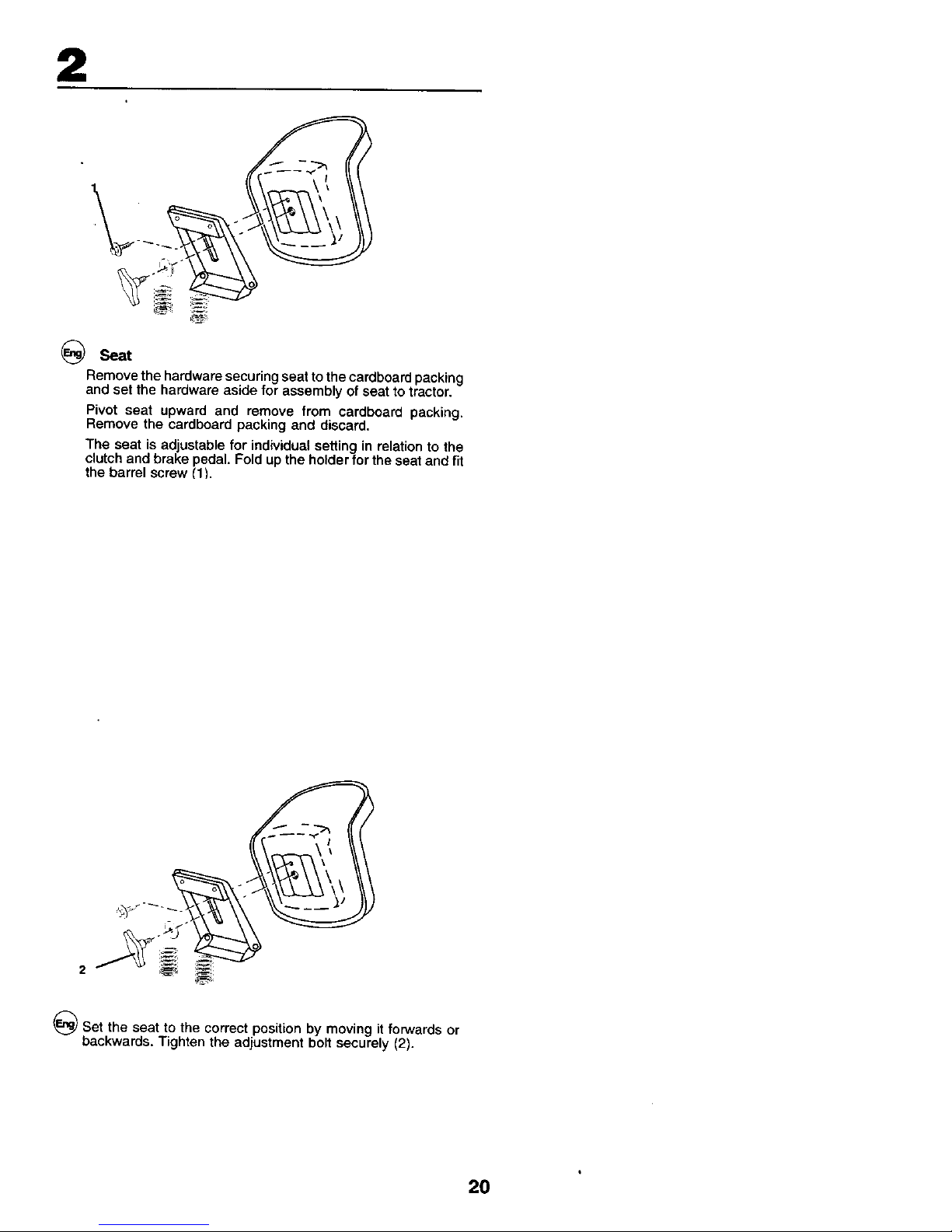
Seat
Remove the hardware securing seat to the cardboard packing
and set the hardware aside for assembly of seat to tractor.
Pivot seat upward and remove from cardboard packing.
Remove the cardboard packing and discard.
The seat is adjustable for individual setting in relation to the
clutch and brake pedal. Fold up the holder for the seat and fit
the barrel screw (11.
_)Set the seat to the correct position by moving it forwards or
backwards. Tighten the adjustment bolt securely (2).
20
Page 10

2
NOTE!
Check that the flex iscorrectly connected to the safety switch
(3) on the seat holder.
21
Page 11
2
I.
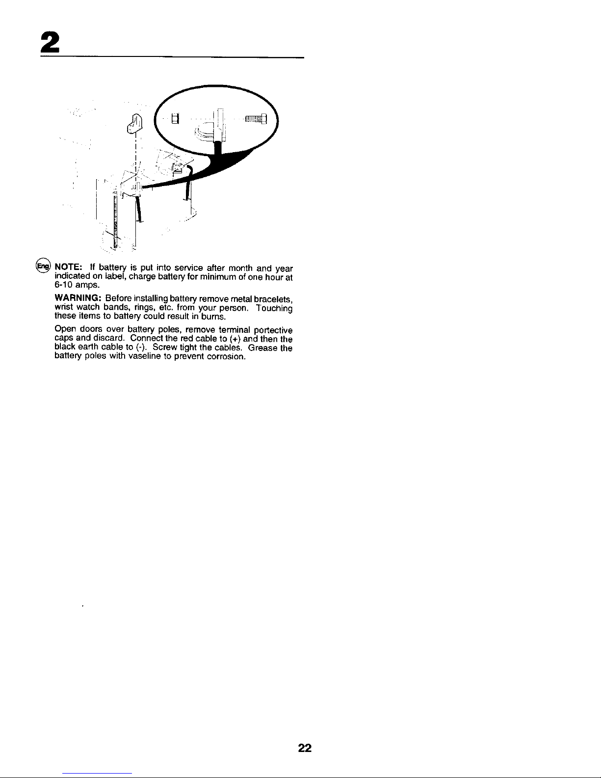
_) NOTE: If battery is put into service after month and year
indicated on label, charge battery for minimum of one hour at
6-10 amps.
WARNING: Before installing battery remove metal bracelets,
wrist watch bands, rings, etc. from your person. Touching
these items to battery could result in bums.
Open doors over battery poles, remove terminal portective
caps and discard. Connect the red cable to (+) and then the
black earth cable to (-). Screw tight the cables. Grease the
battery poles with vaseline to prevent corrosion.
22
Page 12
iI
2
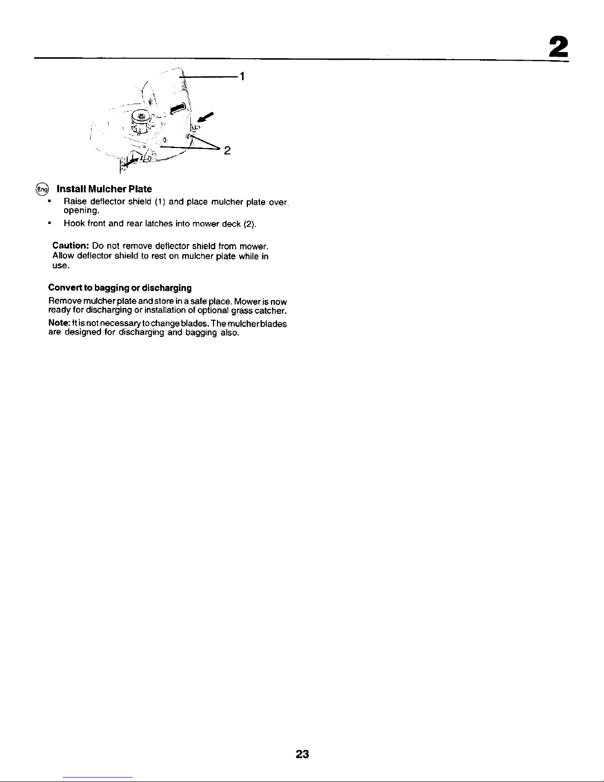
Install Mulcher Plate
• Raise deflector shield (1) and place mulcher plate over
opening.
Hook front and rear latches into mower deck (2).
Caution: Do not remove deflector shield from mower.
Allow deflector shield to rest on mulcher plate while in
use.
Convert to bagging or discharging
Remove mulcher plate and store ina safe place, Mower isnow
ready for discharging or installation of optional grass catcher.
Note: Itis notnecessary tochange blades, The mulcher blades
are designed for discharging and bagging also,
2
23
Page 13

3. Functional description.
I\1
Positioning of controls
1. Light switch.
2. Throttle control.
3. Brake and clutch pedal.
4. Motion control lever.
5. ConnectionlDisconnection of the cuttlng unit.
6. Quick lifting/lowering of the cutting unit.
7. Ignition look.
8. Parking Brake.
9. Free-wheel control lever.
10. Choke Control.
24
Page 14
3
@
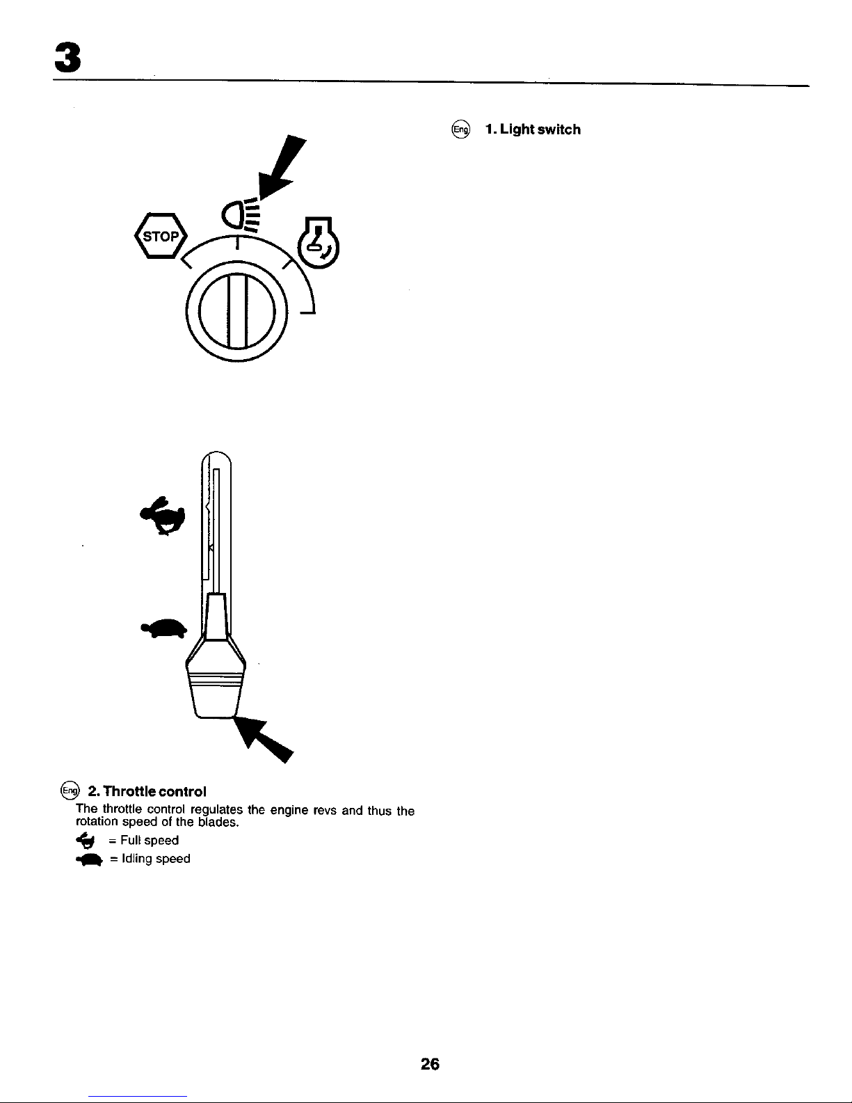
1. Light switch
2. Throttle control
The throttle control regulates the engine revs and thus the
rotation speed of the blades.
= Full speed
= Idling speed
26
Page 15

3
3. Brake and clutch
pedal
Whenthepedalispusheddownthebrakeis appliedandthe
motoris disengaged.
27
Page 16

3
S
F
4. Motion control lever
There are four different positions for this lever:
N = NeutraE (no drive)
S = Slow
F = Fast
a = Reverse
The lever can be moved steplessly between Sand Fto ensure
the required speed.
N
28
Page 17

3
(_ 5. Connection/disconnection of the cutting
unit
Move the lever forwards to connect the drive to the cutting
unit, whereby the drive belt istensioned and the blades begin
to rotate, if the lever is moved backwards the drive will be
disconnected and the rotationof the blades slowed down by
the action of the brake shoes on the pulley.
6. Quick lifting/lowering of the cutting unit
Pull the lever backwards to quickly liftthe cutting unit when
passing over irregularities in the lawn, etc. During transporta-
tion the cutting unit shall be in the highest position. Pull the
lever back untit it locks, To lower the unit: Pull the lever
backwards (1), Push inthebutton (2)and then move the lever
forwards (3).
29
Page 18

3
OFF ON START
(_) 7. Ignition Lock
There are three different positions for the ignition key:
OFF ALL ELECTRIC CURRENT BROKEN.
ON ELECTRIC CURRENT CONNECTED.
START START MOTOR CONNECTED.
WARNING!
Never leave the key in the ignition lock when leaving the
machine on its own.
3O
Page 19

3
8. Parking brake
Connect the parking brake in the following way:
1. Press down the brake pedal to bottom position.
2. Move the parking brake lever upwards and hold in this
position.
3. Release the brake pedal.
To release the parking brake all that is necessanj is to push
down the brake pedal.
31
Page 20

3
_) 9. Free-wheel Control Lever
To tow or move the tractor without the aid of the engine, the
free-wheel control knob must be pulled out and locked in
position.
_) 10. Choke control
When the engine iscold the choke should be pulled out before
starting.When the engine has started and is running smoothly
push the choke in.
32
Page 21

4. Before starting.
_) Filling up
The engine should be run of pure (not oil mixed) unleaded
petrol. Do not fill beyond the lower edge of the filling hole. Do
not fill over max level.
WARNING!
Petrol ishighly inflammable. Proceed with care and fillupwith
petrol outdoors, Do not smoke when filling with petrolor fill up
when the engine is warm. Do not overfill the tank since the
pertrol can expand and overflow. Make sure that the petrol cap
kssecurely tightened after filling, Store petrol in a cool place
in an appropriate container for engine fuel. Check the petrol
tank and pipes.
33
Page 22

4
Oil level
.The combined oil refilling cap and the oil stick is accessible
when the bonnet is lifted forwards. The oil level in the engine
should be checked before each run. Make sure that the tractor
is horizontal. Unscrew the oil stickand wipe clean. Replace the
oil stick and screw tight. Remove again and check the revel.
_) The oil level should lie between the two the oil
markings on
stick, tf more oil is needed add SAE 30 oil to the _FULL"
marking, SAE 5W-30 oil should be used during the winter
(below freezing point).
r
ADD
q'--FULLCAUTION - DO
34
Page 23

4
Tire air pressure
Check the tyre pressure regularly. The pressure in the front
tyres should be 1 bar (14 PSI) and 0,8 bar (12 PSI) in the back
tyres.
35
Page 24

5. Driving.
Starting of motor
Make sure that the cutting unitis inthe transport position (top
position) and that the lever for connection/disconnection of
the cutting unit is in the disconnection position.
(_ Press down the clutch/brake pedal completely and hold
down. Make sure that the motion control lever is in neutral"N".
36
Page 25

5
Pull out the choke control (if engine is cold).
Warm motor: Push the gas control half-way to full gass
position ",,_".
37
Page 26

5
(_) Turn the ignition key to "START position".
NOTE!
Do not run the start motor more than 5 seconds at once. If the
engine will not start, wait about 10 seconds before the next try.
Let the ignition key retum to the "ON" position when the
(_ engine has started and push in the choke control as soon as
the engine is running smoothly. Push the gas control to the
required speed. For cutting: full gas.
38
Page 27

_IMPORTANT! COLD STARTING FOR HYDRO
IMPORTANT: COLD STARTING FOR HYDRO (BELOW
40°F[4°C]) - AFTER STARTING ENGINE AND BEFORE
DRIVING, LET TRANSMISSION WARM UP FOR ONE (1)
MINUTE BY PLACING MOTION CONTROL LEVER IN NEU-
TRAL (N) POSITION AND RELEASING CLUTCH/BRAKE
PEDAL,
5
Move motion control lever tofull forward position and hold
for five (5) seconds. Move lever to full reverse position and
hold for five (5) seconds. Repeat this procedure three (3)
times.
Move motion control lever to neutral (N) position.
Stop tractor by turning ignition key to "OFF" position.
Engage transmission by placing freewheel control in
driving position.
Start engine and move throttle control to slow position.
Drive tractor forward for approximately five feet then
backwards for five feet. Repeat this driving procedure
three times.
Your tractor is now ready for normal operation.
_)T PURGE TRANSMISSION
o ensure proper operation and performance, it is recom*
mended that the transmission be purged before operating
tractor for the first time. This procedurewill remove anytrapped
air inside the transmission which may have developed during
shipping of your tractor.
IMPORTANT: SHOULD YOUR TRANSMISSION REQUIRE
REMOVAL FOR SERVICE OR REPLACEMENT, IT SHOULD
BE PURGED AFTER REINSTALLATION BEFORE OPERAT-
ING THE TRACTOR.
Park tractor on level surface so it will not roll in any
direction. Parking brake must be disengaged for the
following procedure.
Disengage transmission by placing freewheel control in
freewheeling position.
Start engine and move throttle control to slow position. Be
sure parking brake is not engaged.
39
Page 28

5
_) NOTE!
The machine is equipped with a safety switch which
immediately breaks the current to the engine if the driver
leaves the seat with engine running and with the connection/
disconnection lever in position "connection".
I\1
_) Driving
Lower the cutting unit by moving the lever forwards. Release
the brake/clutch pedal slowly. Connect the cutting unit and
move the motioncontrol lever to the required position. Choose
a driving speed which suits the terrain and required cutting
results.
41
Page 29

5
Cutting tips
Clear the lawn from stones and other obiects which can be
thrown away by the blades.
• Localize and mark stones and other fixed objects to avoid
collision.
Begin with a high cutting height and reduce until the
required cutting result is obtained.
The cuttingresult is best with high engine speed (blades
rotate quickly) and low gear (machine goes slowly), if the
grass is too long and thick the ddve speed can be in-
creased by selecting a higher gear or reducing the motor
speed, without affecting the cutting result.
The best lawn is achieved if the grass is cut often. Cutting
becomes more even and the cut grass is more evenly
distributed ore rthe sudace, Total time taken is not greate r,
since higher drive speed can be selected without affecting
the cutting results.
Avoid cutting wet grass. The cutting results will be worse
since the wheels will sink into the soft lawn.
Spray the cutting unit with water underneath after use,
42
Page 30

5
f
_) WARNING!
Do not drive in terrain at an angle of more than max. 10°.
The risk for spark-over backwards is large.
In steep terrain the risk for tipping is considerable.
Avoid stopping and starting in sloping terrain.
Only change gear when the machine is standing still to
avoid damaging the gear box.
J
Drive in right turns so that the cut grass is thrown away
from flower beds and paths, etc. For larger lawns the
drive direction shoutd be changed after 2-3 turns so that
the cut grass is thrown towards the area that has already
been cut as shown in the illustration.
43
Page 31

5
f
1
¢
• J
Switching offthe engine
Move the gas control to =NI". Disconnect the cutting unit by
moving the connect/discon-nect lever downwards. Lift up the
cutting unit and turn the ignition key to "OFF" position. Allow
the engine to idle for 1-2 minutes to cool down before switching
off after a hard work.
_ WARNING!
Do not iteave the ignition key in the machine when not in use
to prevent children and other aunauthorized persons starting
the engine.
44
Page 32

6. Maintenance, adjustment.
_) WARNING!
Before servicing the engine or cutting unitthe following shall
be carded out:
• Press down the clutch/brake pedal and engage the
parking brake lever,
• Put gear lever in neutral,
• Move connection/disconnection lever to disengaged
position.
• Switch off engine.
• Remove the ignition cable from the plug.
_) (t)
(2)
Hood
Headlight wire connector
@ Engine hood
Raise hoed,
Unsnap headlight wire connector,
Stand in front of tractor. Grasp hood at sides, tiltforward
and lift off of tractor.
To reinstall, slide hood pivot brackets into slots in frame.
Reconnect headlight wire connector and close hood.
45
Page 33

(_ Maintenance
NOTE: Periodic maintenance should be performed on a
regular basis in order to keep your tractor in good running
condition.
_WARNING: Disconnect spark plug wire to prevent accidental
starting before attempting any repa4r, inspection, or mainte-
nance.
Before each use:
Check oil, lubricate pivot points as necessary.
Check tosee all bolts,nuts, and cotter pinsare inplace and
secure.
Check the battery, terminals and vents.
Recharge slowly at 6 amperes if needed.
Clean air screen.
Keep tractor free of dirt and chaff to prevent engine
damage or overheating.
Check brake operation.
6
47
Page 34

6
_) SERVICE RECORD
FILL IN DATES AS YOU COMPLETE REGULAR SERVICE
Every
200 hours
As Every 8 Every Every Every
Needed hours 25 hours 50 hours 100 hours
Change engine oil ............................................................................ •
Lubricate pivot points ........................................................................ •
Check brake operation .............................. •
Clean air screen .......................................................... •
Clean air filter and pre-cleaner ..................................... •
Replace air cleaner paper cartridge ......................................................................................... •
Clean engine cooling fins .................................................................................... •
Replace spark plug .............................................................................................................. •
Check tire pressure ................................... •
Replace fuel filter ............................ ,............................................................................................................ •
Clean battery and terminals ............................................................. •
Check muffler ........................................................................................................ •
Lubricate ball joints .................................................................................................................. •
Toe-in adjustment ........................... !......... •
Carburetor adjustment ............................ •
49
Page 35

6
Blades
For best results mower blades must be kept sharp. Replace
bent or damaged blades, Sharpening can be carried out with
a file or grinding disc.
NOTE! It is very important that both blades are sharpened
equally to avoid imbalance.
BLADE REMOVAL:
Raise mower to highest position to allow access to blades.
Remove hex bolt, lock washer and flat washer securing
blade.
Install new or resharpened blade with trailing edge up
towards deck as shown.
IMPORTANT:: To ensure proper assemb|y, center hole in
blade must align with star on mandrel assembly.
Reassemble hex bott, tookwasher and flat washer in exact
order as shown.
Tighten bolt securely (27-35 Ft. Lbs. torque).
IMPORTANT: Blade bolt is grade 8 heat treated
52
Page 36

6
_) Brakes
The brakesare locatedinsidetherightrearwheel. The wheel
shouldbe dismantledfor bestaccess.
Press down the clutch/brake pedal and engage the park-
ing brake.
(_1. Measure the distance between the brake lever and the
adjuster nut.
2. The distance should be 40 mm (1.56").
3. Adjust the distance if necessary by first loosening the lock
nut (2) and then adjusting with the nut (1).
(_ WARNING!
Do not forget to tighten the lock nut after completing adjust-
ment.
54
Page 37

6
_ Dismantling of the cutting unit
Work from the right side of the machine.
1. Take off the belt from the engine pulley (1).
2. Remove the small retainer spdng (2) and liff clutch spnng
off the pulley bolt.
3. Remove the large retainer spring (3), slide collar off and
push housing guide out of the bracket.
4. Remove the two rear retainer springs (4) and knockoffthe
axle taps with a hammer.
55
Page 38

6
5. Remove the retainer springs (5), (6), (7) and axles.
6. Pull the laver for lifting/lowering the cutting unit backwards.
7. Pu_lout the cutting unit trom the machine.
IMPORTANT: Ifan attachment other than the mower deck is to
be mounted onthe tractor, remove the front links and hook the
clutch spdng into square hole in frame (8).
(_ Assembly of the cutting un t,
Push in the cutting unit under the machine. The ejector
opening should be to the right.
Assemble in the reverse order to dismantling.
56
Page 39

6
\
_) Replacement of drive belt for cutting unit
1. Dismantle the cutting unit as described previeusley.
2. Work offthe belt fromthe unit'sleft pulley and then from the
other wheels,
3. Pull the belt away from the cutting unit.
4. The new belt ismounted in the reverse order. Check that
the belt lies inside all the belt guides.
57
Page 40

6
A
Adjustment of the cutting unit
A. In the direction of travel
1. Check that the air pressure is correct in all four tyres.
2. Make sure that the machine is on a horizontal surface.
3. Lift up the cutting unit to its highest position.
4. Measure the distances A and B.
_)To achieve best cutting results the cutting unit's front edge (B)
should be about 10 mm (0.375") lower than the back edge (A).
Adjust in the following way to raise the back edge:
1, Loosen the nut (1) on both the left and right levers.
2, Screw the nut (2)the same number of turn s on both levers.
3. When the correc_ distance (A) is obtained this setting is
locked with the nut (1).
58
Page 41

_)(1) Bottom edge of mower
(2)
@ (t)
(2)
Q (1)
(2)
(_) (1)
(2)
(1)
(2)
(_ (1)
(2)
Lift link adjustment nut
Unterkante des M&hwerks
Hubstangen-Stellmutter
Fond du bord de la tondeuse
Ecrou de reglage du raccord de levage
Parte inferior de la esquina de la segadora
Tuerca de ajuste del v&rillaje de levantamiento
Bordo infenore del tagliaerba
Dado di regolazione dell'articolazione di sollevamento
Onderkant van de maaimachine
Bijstelmoer
SIDE-TO-SIDE ADJUSTMENT
Raise mower to highest position.
At the midpoint of both sides of mower, measure height
from bottom edge of mower to ground. Distance"A" should
be the same or within 6mm (1/4") of each other.
If adjustment is necessary, make adjustment on one side
of mower only.
To raise one side of mower, tighten lift link adjustment nut
on that side.
To lower one side of mower, loosen lift link adjustment nut
on that side.
NOTE: Three full turns of adjustment nut will change mower
height about 1/8".
Recheck measurements after adjusting.
6
59
Page 42

6
Replacement of drive belt
Dismantle the cutting unit as described previously
Engage the parking brake and work off the belt upwards from
the pulley (1), theclutch pulley (2) and theengine's drive wheel
(3). Push the belt up between two fan blades and rotate the
fan clockwise until the belt comes loose (4).
6O
Page 43

6
_) 1. Motion Control Lever
2. Neutral Lock Gate
3. Adjustment Bolt
1. Steuerkniippel
2. Verschlussperre in Leedaufstellung
3. Einstellbolzen
(_) 1. Leiver De Controle Du Mouvement
2. Point Mort Vanne De Fermeture
3. Boulon De Reglage
TRANSAXLE MOTION CONTROL LEVER
ADJUSTMENT
The motion control lever has been preset at the factory and
adjustment should not be necessary.
Loosen adjustment bolt in front of the right rear wheel, and
lightly tighten.
Start engine and move motion control lever until tractor
does not move forward or backward•
Hold motion control lever in that position and rum engine
off.
While holding motion control lever in place, loosen the
adjustment bolt.
Move motion control lever to the neutral (N) (lock gate)
position.
Tighten adjustment bolt securely.
NOTE: If additional clearance is needed to get to adjustment
bolt, move mower deck height to the lowest position.
After above adjustment is made, if the tractor still creeps
forward or backward while motion control lever is in neutral
position, follow these steps:
Loosen the adjustment bolt.
Move the motion control lever 1/4 to 1/2 inch in the direction
it is trying to creep•
Tighten adjustment bolt securely•
Start engine and test.
If tractor still creeps, repeat above steps until satisfied•
61
Page 44

_) TRANSAXLE COOLING
The fan and cooling fins of transmission should be kept clean
to assure proper cooling,
Do not attempt to clean fan or transmission while engine is
running or while the transmission is hot.
Inspect cooling fan to be sum fan blades are intact and
clean.
Inspect cooling fins for dirt, grass clippings and other
materials.
TRANSAXLE PUMP FLUID
The transaxle was sealed at the factory and fluid maintenance
is not required. Should the transaxle ever leak or require
servicing, contact your nearest authorized service center/
department.
6
63
Page 45

7. Fault Tracing.
Engine will not start
1, No fuel in fuel tank.
2. Ptug defective.
3. Plug connection defective,
4, Didin carburettor or fuel pipe.
Start motor will not turn engine
1. Battery flat.
2. Poor contact between cable and battery pole.
3, Connection/disconnection level in wrong position,
4. Main fuse defective.
5, Ignition lock defective.
6. Safety contact for clutch/brake pedal defective,
7. Clutch!brake pedal not pushed down,
Engine runs unevenly
1. Gear too high.
2. Plug defective.
3. Carburettor incorrectly set.
4, Air filter blocked.
5, Fuel tank ventilation blocked.
6, Ignition setting defective,
7. Dirt in fuel pipe.
Engine feels weak
1. Air filter _ocked.
2. Plug defective.
3. Did in carburettor or fuel pipe.
4. Carburettor incorrectly set.
Engine overheats
1. Engine ovedoabed.
2, Air inlet or cooling fins blocked.
3. Fan damaged.
4, Too litite or no 0il in engine,
5, Ignition setting defective.
6, Plug defective,
Battery does not charge
1. Fuse defective.
2. One or several cells defective,
3. Poor contact between battery poles and cables,
Lighting does not function
1. Bulbs defective.
2. Switch defective,
3. Shod-circuit in cable.
The machine vibrates
1. Blades loose.
2. Engine loose.
3. Unbalance in one or both blades resulting from damage or
poor balancing after sharpening,
Uneven cutting results
1. Blades blunt.
2. Cutting unit skew.
3. Long or wet grass.
4. Grass stuck under cover.
5. Different air pressures in tyres on left and right side.
6. Gear 1oo high.
7. Drive belt slipping.
64
Page 46

8. Storage.
(_) The following steps should be taken when mowing season is
over:
• Clean the entire machine, especially underneath the
cutting unit cover.
• Touch up all chipped paint surfaces in order to avoid
corrosion,
• Change engine oil.
• Drain the fuel tank. Start the engine and allow it to run until
it is out of fuel.
• Remove the spark plug and pour one table spoon of
engine oil into the cylinder. Pull the engine over in order to
distribute the oil. Return the spark plug.
• Remove the battery. Recharge and store it in a cool, dry
place. Protect the battery from low temperatures.
• The machine should be stored indoors in a dry, dust-free
plase.
WARNING!
Never use gasoline when cleaning. Use degreasing detergent
and warm water instead,
Service
When ordering, we need the following information:
Date of purchase, model, type and sedal number of the
mower.
Always use odginal spare parts.
Contact your local dealer of distributor for warranty service
and repairs.
67
 Loading...