

Page 1

[RaFTSMaN°
25907
Instruction manual
Please read these instructions
carefully and make sure you
understand them before using this
machine.
Page 2

1
2
3
4
Safety specifications.
Sicherheitsbestimmungen.
Consignes de securite.
Assembly.
Zusammenbau.
Montage.
Functional description.
Funktionsbeschreibung.
Description du fonctionnement._
Procedure before start.
MaBnahmen vor dem Anlassen.
Avant de demarrer.
Driving.
Betrieb.
Conduite.
6
7
8
Maintenance, adjustment.
Instandhaltung, Einstellung.
Entretien, r_glages.
Fault tracing.
StSrungssuche.
Recherche des pannes.
Storage.
Aufbewahrung.
Rangement.
We reserve the right to changes without prior notice.
2
Page 3
@
1. Safety Rules &
Safe Operation Practices for Ride-On Mowers
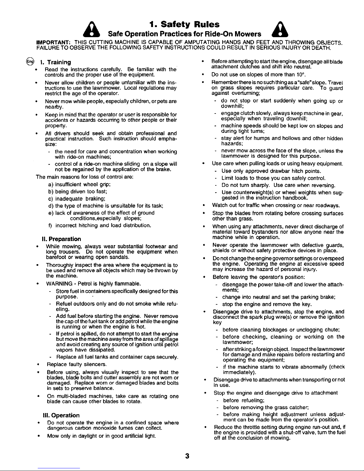
IMPORTANT: THIS CUTTING MACHINE IS CAPABLE OF AMPUTATING HANDS AND FEET AND THROWING OBJECTS.
FAILURE TO OBSERVE THE FOLLOWING SAFETY IN6TRUCTIONS COULD RESULT IN SERIOUS INJURY OR DEATH.
I. Training
Read the instructions carefully. Be familiar with the
controls and the proper use of the equipment.
Never allow children or people unfamiliar with the ins-
tructions to use the lawnmower. Local regulations may
restrict the age of the operator.
Never mow while people, especially children, or pets ere
nearby.
Keep in mind that the operator or user is responsible for
accidents or hazards occurring to other people or their
property.
• All ddvers should seek and obtain professional and
practical instruction. Such instruction should empha-
size:
- the need for care and concentration when working
with ride-on machines;
- control of a dde-on machine sliding on a slope will
not be regained by the application of the brake.
The main reasons for loss of control are:
a) insufficient wheel grip;
b) being ddven too fast;
c) inadequate braking;
d) the type of machine is unsuitable for its task;
e) lack of awareness of the effect of ground
conditions,especially slopes;
f) incorrect hitching and load distribution.
II. Preparation
While mowing, always wear substantial footwear and
long trousers. Do not operate the equipment when
barefoot or wearing open sandals.
Thoroughly inspect the area where the equipment is to
be usedand remove all objects which may bethrown by
the machine.
WARNING ° Petrol is highly flammable.
- Store fuel in containers specifically designed forthis
purpose.
- Refuel outdoors only and do not smoke while refu-
eling.
- Add fuel before starting the engine. Never remove
the cap of the fuel tank or add petrol while the engine
is running or when the engine is hot.
- If petrol is spilled, do not attempt to start the engine
but move the machine away from the area ofspillage
and avoid creating any source of ignition until petrol
vapors have dissipated.
- Replace all fuel tanks and container caps securely.
Replace faulty silencers.
Before using, always visually inspect to see that the
blades, blade bolts and cutter assembly are not worn or
damaged. Replace worn or damaged blades and bolts
in sets to preserve balance.
On multi-bladed machines, take care as rotating one
blade can cause other blades to rotate.
IlL Operation
Do not operate the engine in a confined space where
dangerous carbon monoxide fumes can collect.
Mow only in daylight or in good artificial light.
Before attemptingto start the engine, disengage all blade
attachment clutches and shift into neutral.
Do not use on slopes of more than 10°.
Remember there is no such thing as a"safe" slope. Travel
on grass slopes requires particular care. To guard
against overturning;
- do not stop or start suddenly when going up or
downhill;
- engage clutch slowly, always keep machine in gear,
especially when traveling downhill;
machine speeds should be kept low on slopes and
during tight turns;
stay alert for humps and hollows and other hidden
hazards;
never mow across the face of the slope, unless the
lawnmower is designed for this purpose.
Use care when pulling loads or using heavy equipment.
Use only approved drawbar hitch points.
Limit loads to those you can safely control.
- Do not turn sharply. Use care when reversing.
- Use counterweight(s) or wheel weights when sug-
gested in the instruction handbook.
Watch out for traffic when crossing or near roadways.
Stop the blades from rotating before crossing surfaces
other than grass.
When using any attachments, never direct discharge of
material toward bystanders nor allow anyone near the
machine while in operation.
Never operate the lewnmower with defective guards,
shields or without safety protective devices in place.
Do not change the engine governor settings or overspeed
the engine. Operating the engine at excessive speed
may increase the hazard of personal injury.
Before leaving the operator's position:
- disengage the power take-off and lower the attach-
ments;
- change into neutral and set the parking brake;
- stop the engine and remove the key.
Disengage ddve to attachments, stop the engine, and
disconnect the spark plug wira(s) or remove the ignition
key
- before cleaning blockages or unclogging chute;
- before checking, cleaning or working on the
lawnmower;
- afferstriking aforeignobject. Inspectthelawnmower
for damage and make repairs before restarting and
operating the equipment;
if the machine starts to vibrate abnormally (check
immediately).
Disengage ddve to attachments when transporting or not
in use.
Stop the engine and disengage drive to attachment
before refueling;
- before removing the grass catcher;
- before making height adjustment unless adjust-
ment can be madefrem the operator's position.
Reduce the throttle setting dudng engine run-out and, if
the engine is provided with a shut-off valve, tum the fuel
off at the conclusion of mowing.
3
Page 4

IV. Maintenance and Storage
Keep all nuts, bolts and screws tight to be sure the
equipment is in safe working condition.
Never store the equipment with petrol in the tank inside
a building where fumes may reach an open flame or
spark.
Allow the engine tocool before storing in any enclosure.
To reduce the fire hazard, keep the engine, silencer,
battery compartment and petrol storage area free of
grass, leaves, or excessive grease.
Check the grass catcher frequently for wear or deteriora-
tion.
Replace worn or damaged parts for safety.
If the fuel tank has to be drained, this should be done
outdoors.
On multi-bladed machines, take care as rotating one
blade can cause other blades to rotate.
When machine is to be parked, stored or left unattended,
lower the cutting means unless a positive mechanical
lock is used.
_lL CAUTION: Always disconnect spark plug wire and
place wire where it cannot contact spark plug in
order to prevent accidental starting when setting up,
transporting, adjusting or making repairs.
4
Page 5

(_ These symbols may appear on your tractor or in the literature supplied with the product. Learn and understand their meaning.
R N H L "_ Q_ Q
REVERSE NEUTRAL HIGH LOW FAST SLOW UGHTS ON UGHTS OFF
ENGINE ON ENGINE OFF PARKING BRAKE LOCKED UNLOCKED PARKING BRAKE BATTERY
CLUTCH CHOKE FUEL OIL PRESSURE DIFFEREN'RAL LOCK REVERSE FORWARD
IGNI'IION A'I-rACHMENT ATTACHMENT CAUTION MOWER HEIGHT BEWARE OF
CLUTCH ENGAGED CLUTCH DISENGAGED THROWN OBJECTS
15
Page 6
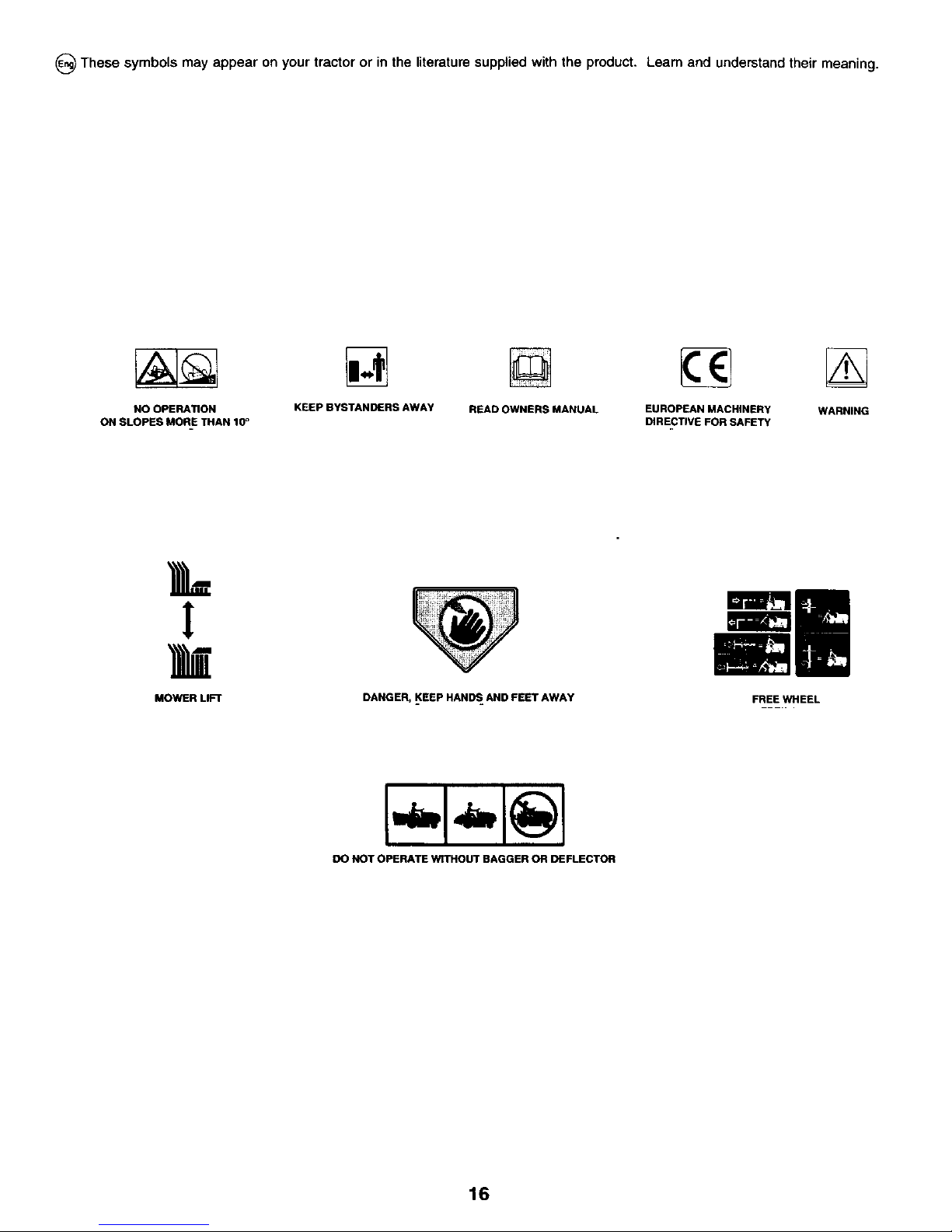
_ These symbols may appear on your tractor or in the literature supplied with the product. Learn and understand their meaning.
NO OPERATION KEEP BYSTANDERS AWAY READ OWNERS MANUAL EUROPEAN MACHINERY WARNING
ON SLOPES MORE THAN 10_ DIRECTIVE FOR SAFETY
MOWER LIFT DANGER, _KEEPHANDS=AND FEET AWAY FREE WHEEL
DO NOT OPERATE WITHOUT BAGGER ON DEFLECTOR
16
Page 7

_.._ N_O [_ FLUSH EYES
SHIELD I I IMMEDIATELY WITH
EYES. I I SULFURIC ACID WATER. GET
EXPLOSIVE GASES I .SPARKS I CANCAUSE HELP FAST.
CAN CAUSE BLINDNESS ,FLAMES BLINDNESS OR
OR INJURY, I ,SMOKING I SEVERE BURNS.
RECYCLE
Mfg. by/I
EPM Products
Baltimore, MD 21226
MADE IN U.S.A.
17
Page 8
2. Assembly.
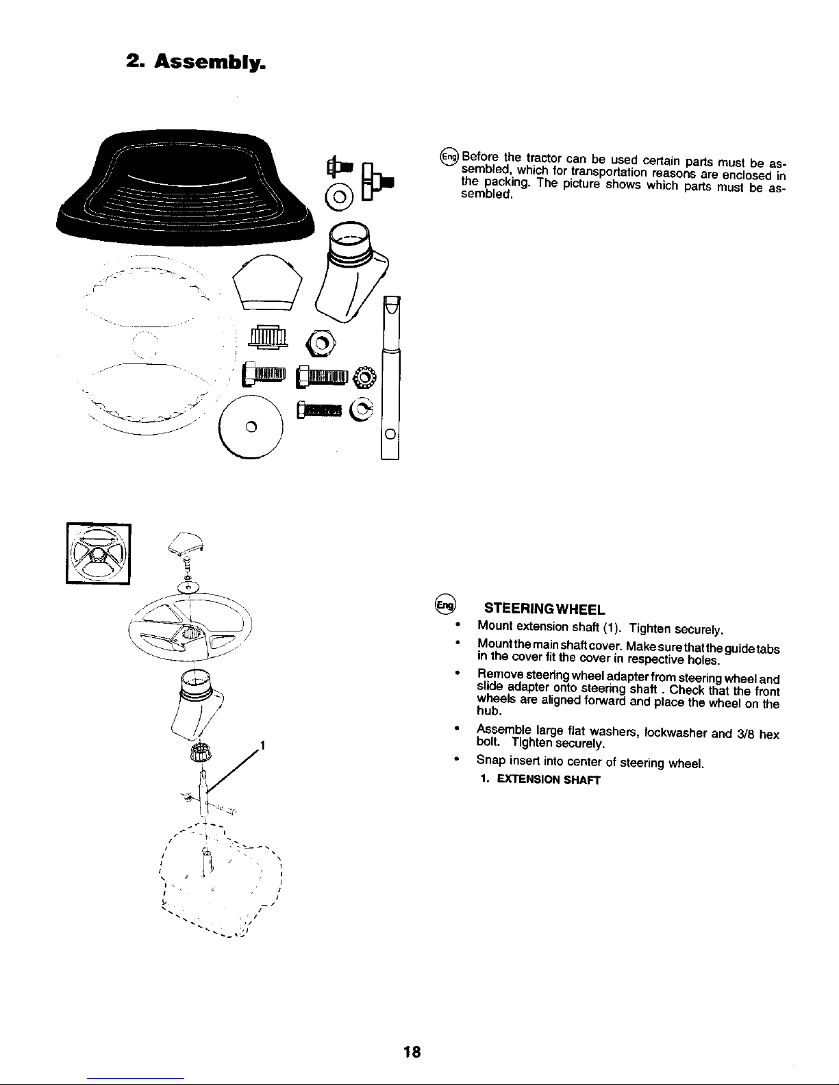
_)Before can certain parts must be as-
the tractor be used
sembled, which for transportation reasons are enclosed in
the packing. The picture shows which parts must be as-
sembled.
©
STEERING WHEEL
Mount extension shaft (1). Tighten securely.
Mount the mainshaftcover. Make sure thatthe guide tabs
in the cover fit the cover in respective hotes.
Remove steering wheel adapter from steering wheel and
slide adapter onto steering shaft. Check that the front
wheels are aligned forward and place the wheel on the
hub.
• Assemble large flat washers, Iockwaeher and 3/8 hex
bolt. Tighten securely.
• Snap insert into center of steering wheel.
1. EXTENSION SHAFT
J
i
I
18
Page 9
2
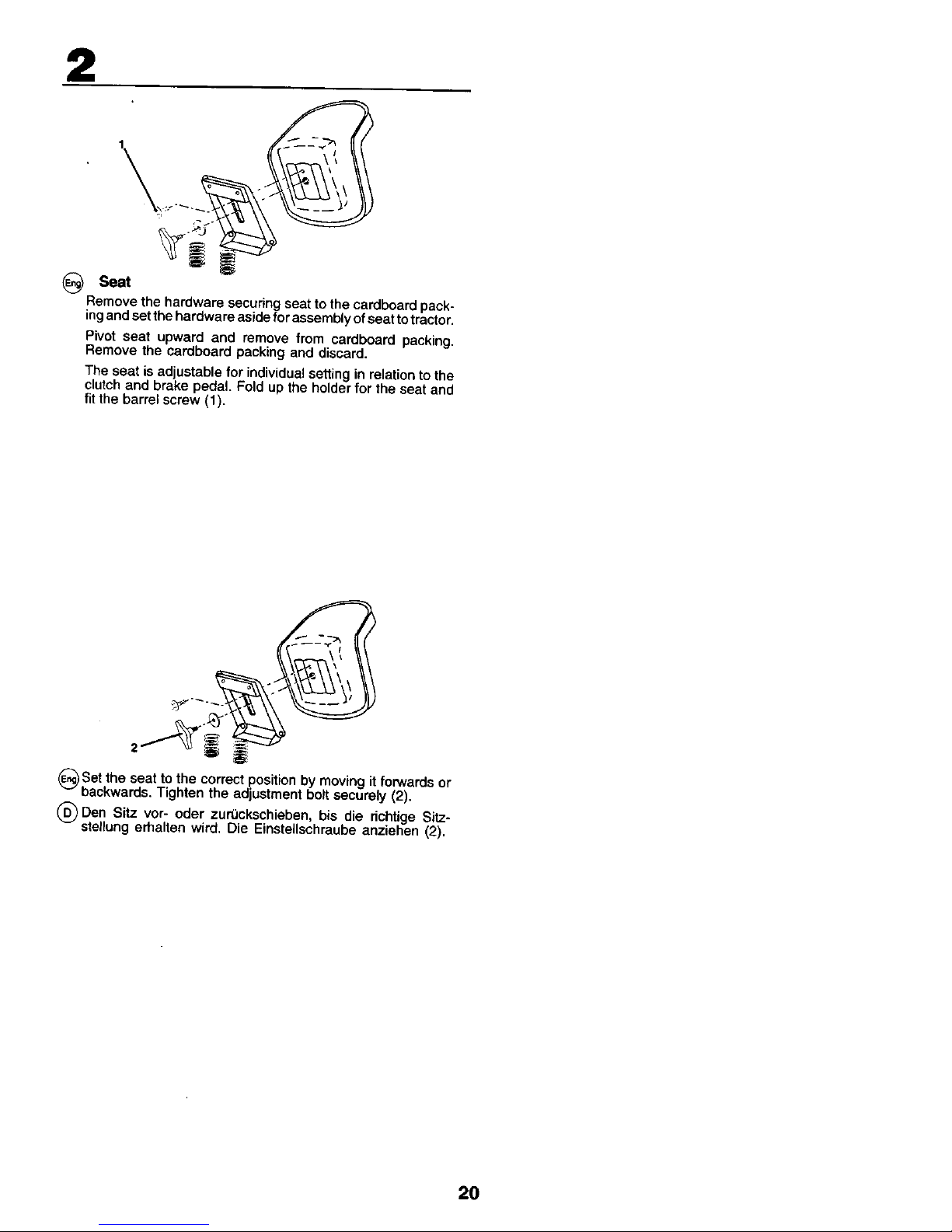
(_ Seat
Remove the hardware securing seat to the cardboard pack*
ingand setthe hardware aside for assembly of seat to tractor.
Pivot seat upward and remove from cardboard packing.
Remove the cardboard packing and discard.
The seat is ad ustable for individual setting in relation to the
clutch and brake peda. Fod up the ho der for the seat and
fit the barrel screw (1).
2
_)Set the seat to the correct position by moving it forwards or
backwards. Tighten the adjustment bolt securely (2).
(_)Den Sitz vor- oder zurOckschieben, bis die richtige Sitz-
stellung erhalten wird, Die Einstellschraube anziehen (2).
20
Page 10

2
NOTE!
Check that the flex iscorrectly connected to the safety switch
(3) on the seat holder.
21
Page 11
2
I
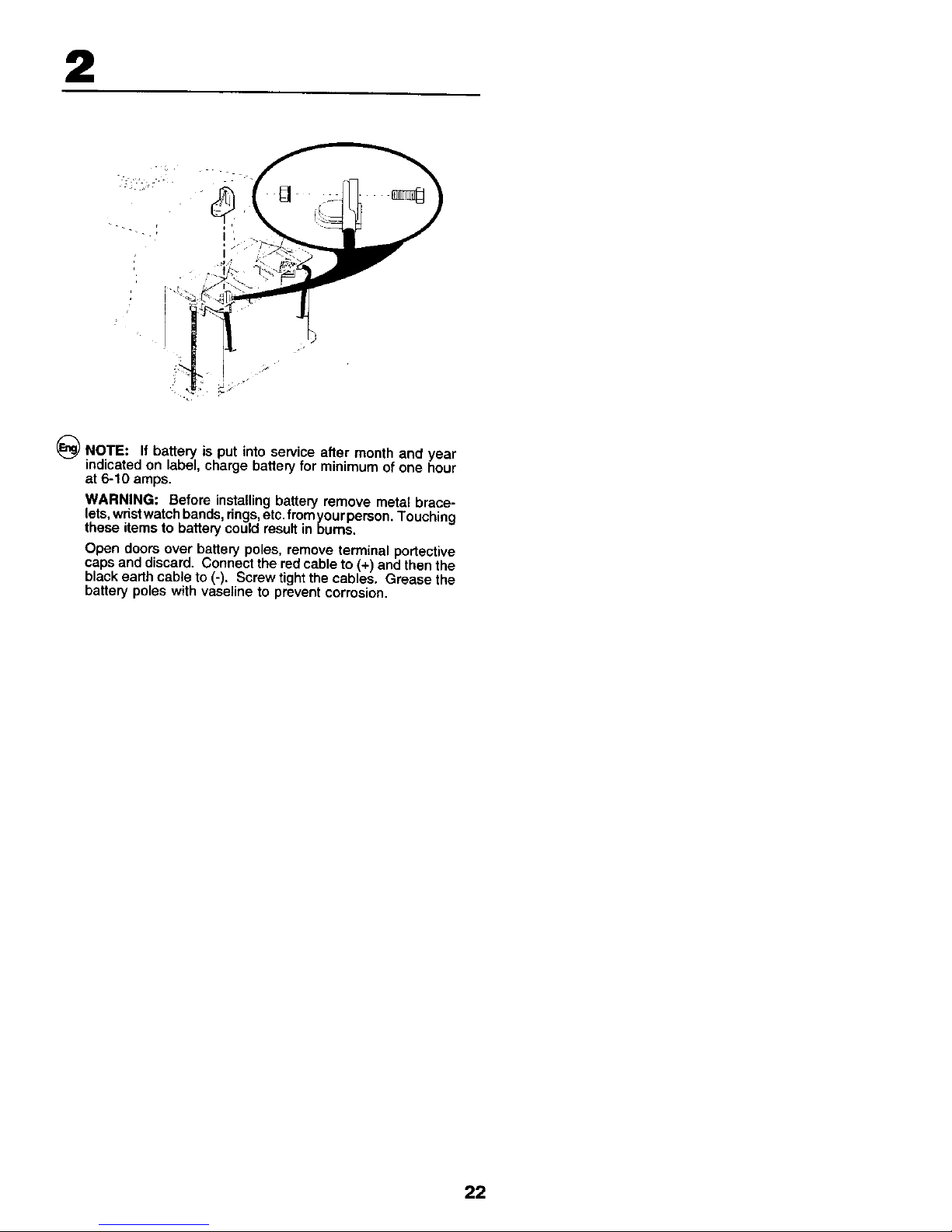
_ NOTE: If battery is put into service after month and year
indicated on label, charge battery for minimum of one hour
at 6-10 amps.
WARNING: Before installing battery remove metal brace-
lets,wrist watch bands, rings,etc. fromyour person. Touching
these items to battery could result in bums.
Open doors over battery poles, remove terminal portective
caps and discard. Connect the red cable to (+) and then the
black earth cable to (-). Screw tight the cables. Grease the
battery poles with vaseline to prevent corrosion.
22
Page 12
2
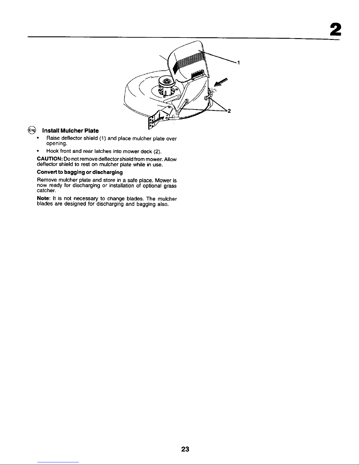
0 InstalIMulcherPlate
Raise deflector shield (t) and place muicher plate over
opening.
Hook front and rear latches into mower deck (2).
CAUTION; Do not remove deflector shield from mower. Allow
deflector shield to rest on mulcher plate while in use.
Convert to bagging or discharging
Remove mulcher plate and store in a safe place. Mower is
now ready for discharging or installation of optional grass
catcher.
Note: It is not necessary to change blades, The mulcher
blades are designed for discharging and bagging also,
23
Page 13
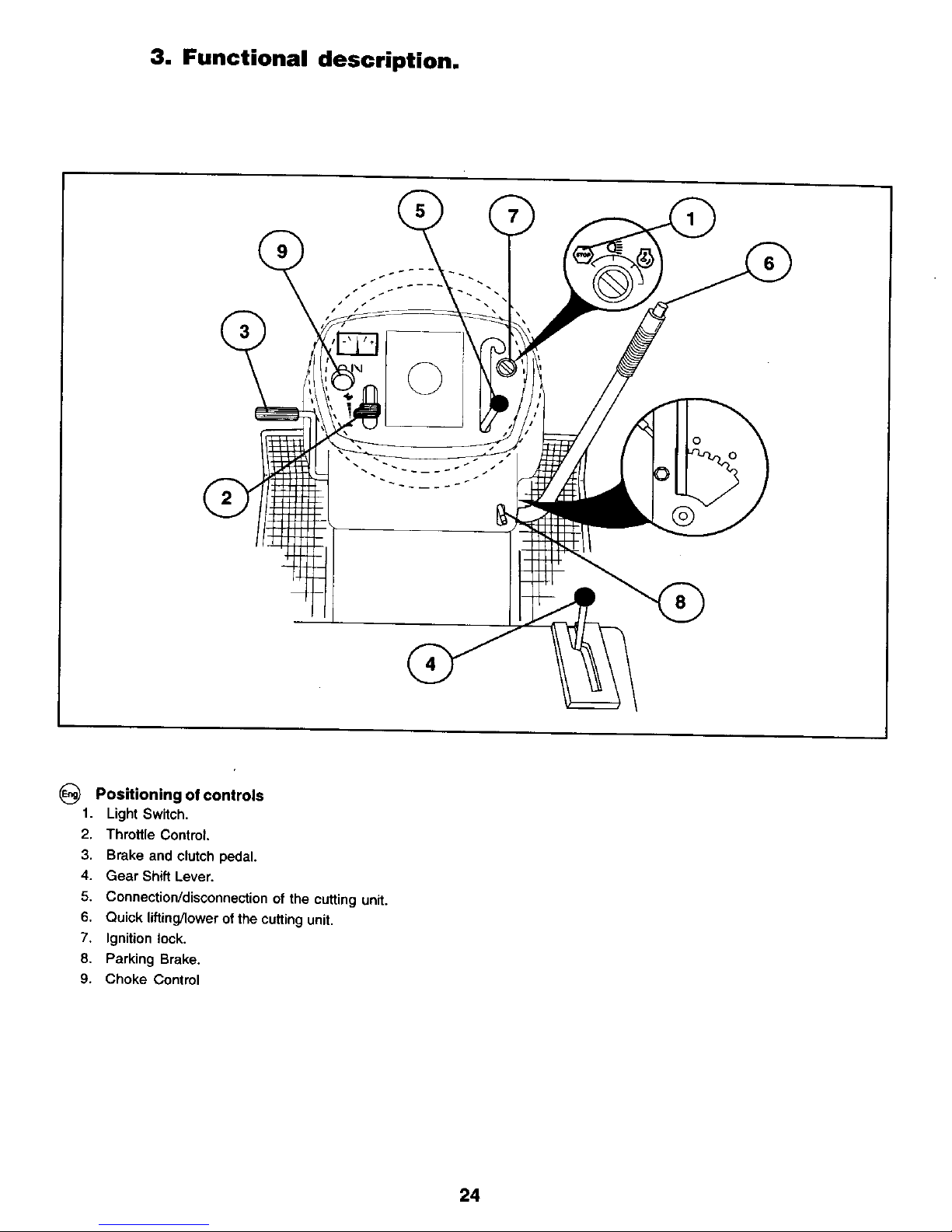
3. Functional description.
_-_ Positioning of controls
1. Light Switch.
2. Throttle Control.
3. Brake and clutch pedal.
4. Gear Shift Lever,
5. Connection/disconnection of the cutting unit.
6. Quick lifting/lower of the cutting unit.
7, Ignition lock.
8. Parking Brake.
9. Choke Contrct
24
Page 14

3
(_ 1. Light switch
@
2. Throttle control
The throttle control regulates the engine revs and thus the
rotation speed of the blades,
= Full speed
= Idling speed
26
Page 15

3
3. Brake and clutch pedal
When the pedal is pushed down the brake is applied and the
motor is disengaged,
27
Page 16

3
4. Gear shift lever
The gear box has positions forward, neutral and reverse.
Gear changing can take place from neutral to topgear without
stopping in each gear position. Disengage the motor at each
gear position! Start can take place irrespective of the gear
lever position.
NOTE!
Stop the machine before changing from reverse to forward
gear, or the opposite. Gear changing between the forward
gears must not take place when the machine is in motion.
28
Page 17

3
(_ 5. Connection/disconnection of the cutting unit
Move the leverforwards to connect the driveto the cutting unit,
whereby the drive belt is tensioned and the blades be_)into
rotate. If the lever is moved backwards the drive will be
disconnected and the rotation of the blades slowed down by
the action of the brake shoes on the pulley.
3
(_ 6. Quick lifting/lowering of the cutting unit
Pull the lever backwards to quickly liftthe cutting unit when
passing over irregularities in the lawn, etc. During transporta-
tion the cutting unit shall be in the highest position. Pull the
lever back until it locks. To lower the unit: Pull the lever
backwards (1). Push inthe button (2) and then move the lever
forwards (3).
29
Page 18

3
OFF ON START
(_ 7. Ignition Lock
There are three different positions for the ignition key:
OFF All electric current broken.
ON Electric current connected.
START Start motor connected.
WARNING!
Never leave the key in the ignition lock when leaving the
machine on its own.
8. Parking brake
Connect the parking brake in the following way:
1. Press down the brake pedal to bottom position.
2. Move the parking brake lever upwards and hold in this
position.
3. Release the brake pedal.
To release the parking brake all that is necessanj is to push
down the brake pedal.
3O
Page 19

3
9. Choke control
When the engine is cold the choke should be pulled out
before starting. When the engine has started and is running
smoothly push the choke in.
31
Page 20

4. Before starting.
G Fill|ng up
The engine should be run of pure (not oil mixed) unleaded
petrol, Do not fill beyond the lower edge of the filling hole, Do
not fill over max level.
WARNING!
Petrol is highly inflammable. Proceed with care and fill up with
petrol outdoors. Do not smoke when filling with petrol or fill up
when the engine is warm. Do not overfill the tank since the
pertrol can expand and overftow. Make sure that the petrol cap
is securely tightened after filling. Store petrol in a cool place
in an appropriate container for engine fuel. Check the petrol
tank and pipes.
32
Page 21

4
(_ Oil level
The combined oil refilling cap and the oil stick is accessible
when the bonnet is lifted forwards, The oil level in the engine
should be checked before each run. Make sure that the tractor
is horizontal. Unscrew the oil stick and wipe clean. Replace
the oil stick and screw tight. Remove again and check the level
(_The oil level should lie between the two markings on the oil
stick. If more oil is needed add SAE 30 oil to the "FULL"
marking. SAE 5W-30 oil should be used dudng the winter
(below freezing point).
CAUTION-DO
33
Page 22

4
Tire air pressure
Check the tyre pressure regularly. The pressure in the front
tyres should be 1 bar ( 14 PSI) and 0.8 bar (12 PSI) inthe back
tyres.
34
Page 23

5. Driving.
(_ Starting of motor
Make sure that the cutting unit isin the transport position (top
position) and that the lever for connection/disconnection of
the cutting unit is in the disconnection position.
(_)Press down the clutch/brake pedal completely and hold
down, Set the gear lever in neutral "N".
Pull out the choke control (if engine is cold).
35
Page 24

5
Warm motor: Push the gas control half-way to full gass
position "4"-
(_) Turn the ignition key to "START position".
NOTE!
Do notrunthe start motor more than 5 seconds at once. If the
engine will not start, wait about 10 seconds before the next
try.
Let the ignition key return to the "ON" position when the
engine has started and push in the choke control as soon as
the engine is running smoothly. Push the gas control to the
(_ required speed. For cuffing: full gas.
36
Page 25

(_ NOTE!
The machine is equipped with a safety switch which
immediately breaks the current to the engine if the driver
leaves the seat with engine runningand with the connection/
disconnection lever in position =connection".Your
machine is also equiped with a system that will not allow
mower to operate if the bagger or optional rear discharge
deflector is not installed properly.
5
Driving
Lower the cuttingunit by movingthe lever forwards. Connect
the cutting unit. Choose a drivingspeed whichsuits the terrain
and required cutting results, Release the brake/clutch pedal
slowly,
37
Page 26

5
@
Cutting tips
Clear the lawn from stones and other objects which can be
thrown away by the blades.
Localize and mark stones and other fixed objects to
avoid collision.
Begin with a high cutting height and reduce until the
required cutting result is obtained.
The cutting result is best with high engine speed (blades
rotate quickly) and low gear (machine goes slowly). If the
grass is too long and thick the drive speed can be in-
creased by selecting a higher gear or reducing the
motor speed, without affecting the cutting result.
The best lawn is achieved if the grass is cut often. Cutting
becomes more even and the cut grass is more evenly
distributed over the surface. Total time taken is not
greater, since higher drive speed can be selected
without affecting the cutting results.
Avoid cutting wet grass. The cutting results will be worse
since the wheels will sink into the soft lawn.
Spray the cutting unit with water underneath after use.
38
Page 27

5
@
f
WARNING!
Do notddve in terrain at an angle of more than max. 10°,
The risk for spark-over backwards is large.
In steep terrain the dsk for tipping is considerable.
Avoid stopping and starting in sloping terrain.
Only change gear when the machine is standing still to
avoid damaging the gear box.
f
f
]
i '#
(_ Ddve in right turns so that the cut grass is thrown away from
flower beds and paths, etc. For larger lawns the drive direction
should be changed after 2-3 turns so that the cut grass is
thrown towards the area that has already been cut as shown
in the illustration.
39
Page 28

5
_Use the teft side of the machine to cut close to trees, bushes
and paths, etc. The blade cuts about 15 mm inside the edge
ofthe cover.
Switching offthe engine
Move the gas contro{ to "gll,".
Disconnect the cutting unit by moving the eonnectJdiscon-nect
lever downwards.
Lift up the cutting unit and turn the ignition key to "OFF"
position.
Allow the engine to idle for 1-2 minutes to cool down before
switching off after a hard work,
4O
Page 29

5
V
WARNING!
Do notfleave the ignitionkey inthe machine when notin use
to prevent children and other aunauthorized persons starl-
ing the engine.
41
Page 30

6• Maintenance, adjustment•
@
WARNING!
Before servicing the engine orcutting unit the following shall
be carried out:
Press down the clutch/brake pedal and engage the
parking brake lever,
• Put gear lever in neutral.
• Move connection/disconnection lever to disengaged
position,
Switch off engine.
Remove the ignition cable from the plug.
J
L
\
@
Engine hood
Raise hood.
Unsnap headlight wire connector.
Stand in front of tractor. Grasp hood at sides, tilt forward
and lift off oftractor.
To reinstall, slide hood pivot brackets into slots in frame.
Reconnect headlight wire connector and close hood.
@ (1) Hood
(2) Headlight wire connector
42
Page 31

6
Maintenance
NOTE: Periodic maintenance should be performed on a
regular basis in order to keep your tractor in good running
condition.
WARNING: Disconnect spark plugwire to prevent accidental
starting before attempting any repair, inspection, or mainte-
nance.
Before each use:
Check oil, lubricate pivot points as necessary.
Check to see all bolts,nuts, and cotter pinsare in place and
secure.
Check the battery, terminals and vents.
Recharge slowly at 6 amperes if needed.
Clean air screen.
Keep tractor free of dirt and chaff to prevent engine
damage or overheating.
Check brake operation.
44
Page 32

G
_) SERVICE RECORD
FILL IN DATES AS YOU COMPLETE REGULAR SERVICE
Every
200 hours
As Every 8 Every Every Every
Needed hours 25 hours 50 hours 100 hours
Change engine oiJ ........................................................................... •
Lubricate pivot points ..................................................................... •
Check brake operation ............................ l
Clean air screen .......................................................... •
Clean air filter and pre-cleaner ................................... •
Replace air cleaner paper cartridg_ ........................................................................................ •
Clean engine cooling fins ................................................................................. •
Replace spark plug ................................................................................................................... •
Check tire pressure .................................
Replace fuel filter ...................................................................................................................................... •
Clean battery and terminals ............................................................
Check muffler ....................................................................... I ........................... •
Lubricate ball joints .............................................................................................................
Toe-in adjustment ................................... •
Carburetor adjustment .............................. •
46
Page 33

6
Blades
For best results mower blades must be kept sharp. Replace
bent ordamaged blades. Sharpening can be carried out with
a file or grinding disc.
NOTE! It is very important that both blades are sharpened
equally to avoid imbalance.
BLADE REMOVAL:
• Raise mower to highest position to allow access to
blades.
• Remove hex bolt, lock washer and flat washer securing
blade.
Install new or resharpened blade with trailing edge up
towards deck as shown.
IMPORTANT:: To ensure proper assembly, center hole in
blade must align with star on mandrel assembly.
• Reassemble hex bolt, lock washer and flat washer in
exact order as shown.
Tighten bolt securely (27-35 Ft. Lbs. torque).
IMPORTANT: Blade bolt is grade 8 heat treated
49
Page 34

6
_1. Measure the distance between the brake lever and the
adjuster nut.
2. The distance should be 38mm (1.5").
3. Ad ust the distance if necessary by first loosening the lock
nut (2) and then ad ust ng w th the nut (1).
(_ Brakes
The brakes are located inside the right rear wheel. The wheel
should be dismantled for best access.
Press down the clutch/brake pedal and engage the park-
mg brake.
(_ WARNING!
Do not forget to tighten the lock nut after completing adjust-
ment.
51
Page 35

6
Dismantling of the cutting unit
Work from the right side of the machine.
1. Take off the belt from the engine pulley (1),
2, Remove the small retainer spring (2) and liftclutch spring
off the pulley bolt.
3. Remove the large retainer spring (3), slide collar off and
push housing guide out of the bracket.
4. Remove the two rear retainer springs (4) and knock offthe
axle taps with a hammer.
52
Page 36

6
5. Remove the retainer springs (5), (6), (7) and axles.
6. Pull the lever for lifting/lowering the cutting unit back-
wards.
7. Pull out the cutting unitfrom the machine.
IMPORTANT: |f an attachment other than the mower deck is
tobe mounted on the tractor, remove the front links and hook
the clutch spring into square hole in frame (8).
(_ Assembly of the cutting unit
Push in the cutting unit under the machine. The ejector
opening should be to the right.
• Assemble in the reverse order to dismantling.
53
Page 37

6
Replacement of drive belt for cutting unit
1. Dismantle the cutting unit as described previousley.
2. Work offthe belt from the unit's leftpulley and thenfrom the
other wheels,
3. Puttthe belt away from the cutting unit.
4. The new belt is mounted in the reverse order. Check that
the bertliesinsideatlthebeltguides,
(_ Adjustment of the cutting unit
A. In the di_.otion of travel
1. Check that the air pressure is correct in all four lyres.
2. Make sure that the machine is on a horizontal surface,
3. Liftup the cutting unitto its highest position.
4. Measure the distances A and B.
54
Page 38

6
o o
(_To achieve best cutting results the cutting unit's front eclQe(B)
sh I . v . .
ou d be about 10 mm (0.375) lower than the back edge (A).
Adjust in the following way to raise the back edge:
1. Loosen the nut (1) on both the left and right levers.
2. Screwthe nut (2) the same number of turn s on both levers.
3. When the correct distance (A) is obtained this setting is
locked with the nut (1).
55
Page 39

6
(t) Bottom edge of mower
(2) Lift link adjustment nut
SIDE-TO-SIDE ADJUSTMENT
Raise mower to highest position.
At the midpoint of both sides of mower, measure height
from bottom edge of mower toground. Distance"A" should
be the same or within 6mm (1/4") of each other.
Ifadjustment is necessary, make adjustment on one side
of mower only.
To raise one side of mower, tighten lift link adjustment nut
on that side.
To lower one side otmower, loosen lift link adjustment nut
on that side.
NOTE: Three full turns of adjustment nut will change mower
height about 1/8".
Recheck measurements after adjustinQ.
56
Page 40

(b
6
Replacement of drive belt
Dismantle the cutting unit as described previously
Engage the parking brake and work off the belt upwards from
the pulley (1), the clutch pulley (2) and the engine's drive wheel
(3). Work off the belt upwards from the pulley at the rear axle
(4).
(_ Assemble in the reverse order to dismantling. Check that the
belt lies inside all the belt guides. Use odginal belts only when
replacingf
(_1. Gear Shift Lever
2. Neutral Lock Gate
3. Adjustment Bolt
57
TRANSAXLE GEAR SHIFT LEVER NEUTRAL
ADJUSTMENT
The transaxle should be in neutral when the gear shift lever
is in neutral (N) (lock gate) position. The adjustment is preset
at the factory; however, if adjustment is needed, proceed as
follows:
Make suretransaxle is in neutral (N).
NOTE: When thetractor rearwheels move freely, the transaxle
is in neutral.
Loosen adjustment bolt in front of the right rear wheel.
Position the gear shift lever in the neutral (N) position.
Tighten adjustment bolt securely.
NOTE: If additional clearance is needed to get to adjustment
bolt, mowe mower deck height to the lowest position.
Page 41

7. Troubleshooting.
_) Engine will not start
t. No fuel in fuet tank.
2. Plug defective.
3. Plug connection defective.
4. Dirt in carburettOr or fuel pipe.
Start motor will not turn engine
1. Battery flat.
2. Poor contact between cable and battery,/pole.
3. Connection/disconnection level in wrong position.
4. Main fuse defective.
5. Ignition lock defective.
6. Safety contact for clutch/brake pedal defective.
7. Clutch/brake pedal not pushed down,
Engine runs unevenly
1. Gear too high.
2. Plug defective.
3. Carburattor incorrectly set.
4. Air filter blocked,
5, Fuel tank ventilation blocked,
6. ignition setting defective.
7. Dirt in fuel pipe.
Engine feels week
1. Air filter blocked.
2. Plug defective.
3. Dirt in carburettor or fuel pipe.
4. Carburettor incorrectly set.
Engineoverheets
1. Engine ovedoaded,
2, Air inlet or cooling fins blocked.
3, Fan damaged.
4, Too little or no oil in engine,
5, Ignition setting defective.
6, Plug defective.
Battery does not charge
1. Fuse defective.
2. One or several cells clefective.
3. Poor contact between battery poles and cables.
Lighting does not function
1. Bulbs defective.
2. Switch defective.
3. Short-circuit in cable.
The machine vibrates
1. Blades loose.
2. Engine loose.
3, Unbalance in one or both blades resulting from damage
or poor balancing after sharpening,
Uneven cutting results
1. Blades blunt.
2. Cutting unit skew.
3. Long or wet grass.
4. Grass stuck under cover.
5. Different air pressures in lyres on left and dght side.
6. Gear too high.
7, Ddve belt slipping.
59
Page 42

8. Storage.
_)The following steps should be taken when mowing season
IS over:
• Clean the entire machine, especially underneath the
cutting unit cover.
• Touch up all chipped paint surfaces in order to avoid
corrosion.
Change engine oil.
Drain the fuel tank. Start the engine and allow it to run until
it is out of fuel.
Remove the spark plug and pour one tabte spoon of
engine oil into the cylinder. Pull the engine over in order
to distribute the oil. Return the spark plug.
Remove the battery. Recharge and store it in a cool, dry
place. Protect the battery from low temperatures.
The machine should be stored indoors in a dry, dust-free
place.
WARNING!
Never use gasoline when cleaning. Use degreasing deter
gent and warm water instead.
Service
When ordedng, we need the following information:
Date of purchase, model, type and sedal number of the
mower. Always use odginal spare parts, Contact your local
dealer of distributor for warranty service and repairs.
62
Page 43

,++++,,.,o.oo_o ItlIAVTIMIIII +, Prinled in U.S.A.
 Loading...