

Page 1
CRAFr.3
_xeRouter Table
:CAUTION!_ReadAllInstructionsCarefully
(RouterNotIncluded)
i
i
Pa_No.49LCN:59
Solday:
SEARS,ROEBUCKAndCO.
3333 BeverlyRoad,
HoffmanEstates,IL60179
Made In U,S.A.
Printed h7U,S.A.
Page 2

FAILURETOHEEDALLSAFETYAND OPERATINGINSTRUCTIONS
ANDWARNINGSREGARDINGUSEOFTHIS PRODUCTCANRESULT
IN SERIOUS80DILYINJURY.
GENERALSAFETYINSTRUCTIONSFORPOWERTOOLS
1. KNOWYOURPOWERTOOL
Readthe owner'smanualcarefully.Learnits applicationand
limitationsaswell asthe specificpotentialhazardspeculiarto this
toot.
2. GROUNDALLTOOLS(UNLESSDOUBLEINSULATED)
Iftool isequippedwith anapproved3-conductor cord and a3-
prong groundingtype plug,it should bepluggedintoathreehole
electricalreceptacle,Ifadapteris usedto accommodatea two-
prong receptacle,theadapterwire must be attachedto known
ground,(usuaflythescrewsecuring receptaclecover plate).Never
removethird prong.Neverconnectgreen ground wire to a
terminal.
3. KEEPGUARDSIN PLACE
Inworking order,andin properadjustmentand alignment,
4. REMOVEADJUSTINGKEYSANDWRENCHES
Formahabitof checkingto seethat keysandadjusting wrenches
areremovedfrom too! beforeturning it on.
5. KEEPWORKAREACLEAN
Clutteredareasandbenchesinviteaccidents,Floor mustnot be
slipperyduetowax or sawdust.
6. AVOIDDANGEROUSENVIRONMENT
Don't usepowertools in dampor wet locationsor exposetllem to
rain.Keepwork areawel!lighted: Provideadequatesurrounding
work space.
7. KEEPCHILDRENAWAY
All visitors shouldbe kepta safedistancefrom work area.
8. MAKEWORKSHOPKID-PROOF
Usepadlocks,masterswitches, or removestarterkeys.
9, DON'TFORCETOOLS
It wilt do the job betterand saferatthe rate for which it was
designed,
10. USERIGHTTOOL
Don'tforcetoot or attachmentto do a job it was not designedfor.
11. WEARRIGHTAPPAREL
Do notwearlooseclothing,gloves,necktiesor jewelry (rings,
wrist watches)to getcaugt]tin moving parts, Nonslipfootwearis
recommended,Wearprotectivehair coveringto contain long flair.
Rolllong sleevesabovethe elbow.
12. USESAFETYGOGGLES(HeadProtection)
WearSafetygoggles(mustcomplywith ANSI'Z87,1)atalltimes.
Also, usefaceor dust mask,if cutting operationisdusty,andear
protectors (plugsor muffs) during extendedperiodsofoperation.
13. SECUREWORK
Useclamps or a viseto hold work whenpractical, It's saferthan
using your hands,andit frees both handsto operatetool,
14. DON'TOVERREACH
Keepproperfooting and balanceatatftimes.
i5. MAINTAINTOOLSWITHCARE
Keeptoolssharpand cleanfor bestand safestperformance.
Follow instructionsfor lubricatingand changingaccessories.
16. DISCONNECTTOOLS
Beforeservicing,whenchangingaccessoriessuchas blades,bits,
cutters,etc.
17. AVOIDACCIDENTALSTARTING
Make sureswitch is in "OFF"positionbeforepluggingin.
18. USERECOMMEND_EDACCESSORIES
Consulttheowner's manualfor recommendedaccessoriesand
follow the instructions,Theuseof improper accessoriesmay
causehazards.
19. NEVERSTANDONTOOL
Serious injurycould occur if the tool is tippedor if the cutting tool
is accidenta!lycontacted.Do notstore materialsaboveornearthe
tool makingit necessaryto stand onthe tool to reachthem.
20. CHECKDAMAGEDPARTS
Beforefurther useof thetool, any guardor other partthat is
damagedshould becarefullycheckedto ensurethat it will operate
properlyand perform its intendedfunction.Checkforalignmentof
moving parts,binding of moving parts,breakageof parts,
mounting,andany otherconditions that may affect its operation.A
guard or anyother part that is damagedshould be properly
repairedor replaced.
21. DIRECTIONOF FEED
Feedwork intoa bladeor cutteragainstthedirection of rotation of
the bladeor cutter only.
22. NEVERLEAVETOOLRUNNINGUNATTENDED
Turn poweroff. Don't leavetool untilit comestoa completestop,
Page 3
ENERALSAFETYI UCTI THE
LEWITHUNITIZEDFENCE.
1. ALWAYSUSEEYEPROTECTION
Theoperationof any powertoo!can result inforeign objectsbeing
thrownintotheeyes,which canresult in severeeyedamage.
Alwayswear safetygogglesbeforecommencingpowertool
operation,Safetygogglesareavailableat Searsretailor catalog
stores,
2. KEEPHANDSCLEAROFBITSANDWORKINGAREA
3. MAKEANOUSEAPUSHSTICKTOMOVESMALL
WORKPIECESACROSSTHECUTTINGAREA.
4, KEEPROUTERCLEANAFTEREVERYUSE,CLEANSAWDUST
OFFTHEROUTER.
5. YOURROUTERTABLEiS PROVIDEDWITHADUST
COLLECTINGATTACHMENTALWAYSUSESHOPVACFORALL
ROUTINGOPERATIONSREQUIRINGUSEOFFRONTSIDEOF
UNITIZEDFENCE.(FRONTSiDEtS THESIDEWITHTHE
CRAFTSMANLABEL).
NOTE:Motors usedon wood-working tools areparticularly
susceptibleto theaccumulationof sawdustandwood chips and
should be"vacuumed"frequentlyto preventinterferencewith
normal motor ventilation.
6. CHECKFUNCTIONOFGUARDBEFOREEACHUSE.REMOVE
ALLDUSTANDCHIPSFROMGUARDAREAASNEEDEDTO
MAINTAINGUARDFUNCTION.
7. NEVERPUTYOURFINGERSUNDERTHEGUARDWHENTHE
ROUTERISPLUGGEDIN.
8, ALWAYSUSETHEROUTERTABLEFENCETO GUIDETHE
WORK.DONOTWORKFREEHAND.
Whenusingpilottype bits,keepthe fencesas closeto the pilotas
possibleto provideadditionalbackupand additionalguidanceand
to avoidchancesof an accidentandpossiLllepersonalinjury, ,
9. ALWAYSFEEDAGAINSTTHEROTATIONOFTHECUTTER
WHENROUTINGON THEROUTERTABLE.FEEDWORKPIECESIN
THEDIRECTIONOFTHEARROWASSHOWNONTHELABELON
THESIDEOFTHEFENCEBEINGUSED(WHENFACINGTHE
TABLEFRONT).
10. FORALLEDGECUTTINGANDENDCUTrlNGOPERATIONS,
USEFRONTSIDEOFUNITIZEDFENCE.USEBACKSIDEOF
FENCEONLYFORROUTINGOPERATIONSAWAYFROMEDGEON
THEUNDERSIDEOFWORKPtECESUCHASGROOVING,
FLUTING,VEINING,CROWNMOLDING,ETC.
11. WHENENDCUTTINGONWORKPIECES'4"WIDEOR LESS,
CLAMPANDHOLDAND FEEDTHEWORKPIECEWITHTHEPUSH
BLOCKUSINGBOTHHANDS,AS SHOWNiNFIG. #23. KEEP
FINGERSCLEAROF BITWHENMOVINGWORKPIECEACROSS
THECUTTINGAREA.NEVERPLACEYOURHANDSLOWERTHAN
THETOPOFRETRACTABLEGUARD.
12. ROUTERBITSARE_:_rREMELYSHARP.
Beextracarefulwhenworking around them.
13, SOMEROUTERS,WHENUSEDINAN UPSIDEDOWN
POSITION(SUCHASONAROUTERTABLE),WILLFALL(OR
DROP)OUTOFTHEROUTERBASEWHENTHEBASECLAMPIS
LOOSENED+IT IS THEREFOREABSOLUTELYNECESSARYTO
SUPPORTTHEROUTERMOTORFROMBELOWWHENTHEBASE
CLAMPIS LOOSENEDTO MAKEADJUSTMENTS,ORFORANY
OTHERREASON.
t4. ALWAYSLOOKUNDERTHETABLEATTHESWITCHWHEN
TURNINGTHEROUTERON!OFFANDTOUCHNOTHINGBUTTHE
SWITCH,NEVERREACHUNDERTHETABLEWHENROUTERtS
RUNNINGFORANYOTHERREASON.
NOTE:It isfar more safeand convenientto usea"Craftsman
+25183RouterTableSwitchpackage".Thisswitch providesa key
o 1
peratedON/OFFbutton-whichallowsfast andeasyaccesswhen
and if it becomesnecessaryto turn the router"OFF"quickly,The
keycan beremovedto renderthe switch inoperableto
unauthorizedpeople.
15. MOUNTROUTERTABLEFIRMLYANDSECURELYTOA
WORKSURFACEBEFOREUSE.FAILURETO DOSOCOULD
CAUSETABLETOTiP OVERORSLIDEDURINGOPERATION
RESULTINGIN PROPERTYDAMAGEAND/ORSERIOUSBOOILY
INJURY.
16. BEFOREMAKINGANYCUT,UNPLUG
ROUTERANDRETRACTGUARDTO
MAKEABSOLUTELYSURETHATRETRACTABLEGUARDCLEARS
THEROUTERBIT,ANDTHEGUARDIS FUNCTIONING
NORMALLY.SEEFIG.#16.
17. WARNING:ROUTERVIBRATIONS
SOMETIMESCANCAUSEFASTENERS
FORTHETABLE,THEROUTERANDTHEUNITIZEDFENCETO
GETLOOSErPERIODICALLYCHECKFASTENERSTOMAKESURE
THEYARETIGHTAND SECURE,
Page 4
INTRODUCTION
Howoftenhaveyou neededalargeguiding surfaceon a router table?YourCraftsmanRouterTablewith UnitizedFencecomeswith ttle
following:
• A unique4" highunitizedfencedesignedtoassist end grain
routingfor makingtenons,slidingdovetailsandtongue and
groovejoints along with most edgeand facecutting operations.
• A speciallydesignedpushblockwith quick clamp for back up
and clampingboardsup to 4"width for endgrain routing.
• An accurateandquick adjustingjointing fenceadjustableto
properjointing depth of cut.
• Reversingfeatureof unitizedfencedesignedto enablerouting
operationslikegrooving,fluting, veiningandcrown moldingetc.
up to 2_" awayfrom theedgetowards themid,die of the board.
• Twoguardsfor operationon either sideof ihe unitizedfence.
• Dustco!lectingattachmentfor most sllop vacuumhook ups,
• Extensionsthat providea largework surface.
If orderto facilitatehandlingand minimizeany damagethat might occur during shipment,your newroutertable is packaged
unassembled.We knowyouare anxiousto seewhatyOurnew too! wil! do, but a few minutesspent nowcarefullyreadingthefollowing
instructionswill resultin lessfrustration and more enjoyableoperationlater,
Startbycheckingandaccountingfor all the looseparts, If anypartsare missing,contact your local Craftsmanretailor hardwarestore
outletfor replacement.
OPTIONALROUTERTABLEACCESSORIES
#25326CRAFTSMANUNIVERSALADAPTERPLATE,for mounting non-Craftsman1/4"shank routersto Craftsmanrouter accessories.
#25183CRAFTSMANROUTERTABLEPOWERSWITCH,for turning routerand other accessories"on" and"off" from the front of the
routertable, i
#25468CRAFTSMANGUIDEMASTERRouterTablePush Shoe,aids in push shoeand hold down operations,accuratemeasurementand
routertablesetup,transforms into a miter gauge,and givesquick set up for 1/2"slidingdovetailjoints.
#25489CRAFTSMANROUTERTABLEFLOORSTAND,placesrouter tablesat convenientworking height,hasadjustablefloor levelers,
andtwo steelshelvesfor storage,
UNPACKINGANDCHECKINGCONTENTS
Referto PartsList on Page16
YOUMUST READANDUNDERSTANDALLTHEINSTRUCTIONSCOMPLETELYBEFOREATTEMPTINGTO
ASSEMBLEANDOPERATEYOURROUTER/ROUTERTABLE,
TOOLSREQUIRED
, A smalland medium sizescrewdriver.
• A small or medium sizeadjustablewrench,
• An electricalor hand drill with 1/8"drill bit,
• Hammer
Page 5
ASSEMBLYOFEXTENSIONSANDLEGS
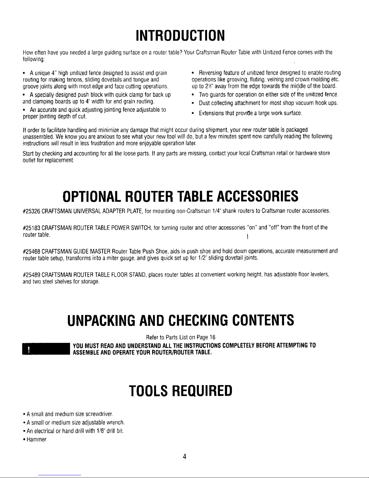
t. ToassembletheEXTENSIONSand LEGSto ROUTERTABLE,
placetable,top side down, on a smooth, flat surfi_ce,andposition
theLEGSandEXTENSIONSrelativeto the TABLEasshown in
Figure1. htsertthe #10-32 x Yi'screwthrough the LEGand install
lock washerandnut. This is to bedone for eachtableleg.
2, Makesureall screws andnuts aresecurelytightened,
3.Turnthe tabletop sideup andcheckto see that tfm
EXTENSIONSare evenwithor slightly belowthe tabletop.
4, In no caseshouldthe EXTENSIONSbehigher thanthe table, or
elsetheymay interferewith the workpieceduring routing causing
a conditionthat can resultin possibleserious injury.
5. If the extensionsarehigherthanthetop ofthe table, loosenthe
screwsholdingtheEXTENSIONSandrepositionthem so they art;
evenwith or slightly lower thanthe top oftable, SECURELY
TIGHTENALL SCREWSANDNUTSAGAIN,
6.Todoublecheck,slidea flat pieceof woodalong the top of the
tableboth directions,Makesurethatthe end of the wood moves
freelywithout contactingthe edgeof the EXTENSIONnextto table,
DONOTPLACEHEAVYOBJECTSOR PRESS
HEAVILYONTHEEXTENSIONSORELSE
THEYMAYBEDAMAGEDCAUSINGACONDITIONTHATMAY
CANRESULTIN POSSIBLESERIOUS80DtLYINJURYDURING
ROUTING.
FIGURE 1
MOUNTINGROUTERTO TABLE
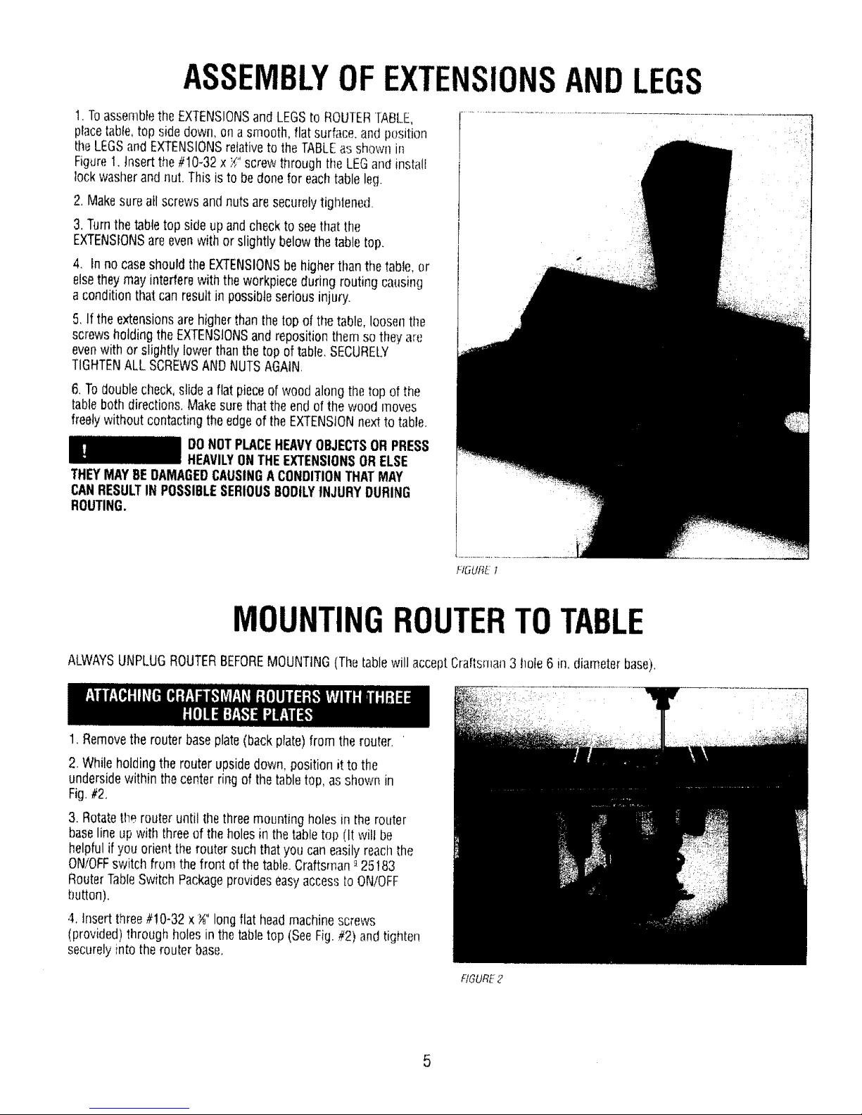
ALWAYSUNPLUGROUTERBEFOREMOUNTING(Thetablewill acceptCraftsman3 hole 6 in. diameterbase).
, i:f •
1. Removethe routerbaseplate(back plate)from the router. '
2. Whileholding the router upsidedown,position it to the
undersidewithin thecenterring of the tabletop, as shown in
Fig.#2,
3. Rotatethe router until thethree mountingholesin the router
baselineup with threeof the holes in thetabletop (It will be
helpfulif you orient therouter suchthat you caneasilyreachthe
ON/OFFswitch from the front of thetable.Craftsman_-25183
RouterTableSwitchPackageprovideseasyaccessto ON/OFF
button).
4. Insertthree#!0-32 x _" longflat headmachinescrews
(provided)throughholesin the tabletop (SeeFig,#2)and tighten
securelyinto the routerbase.
FIGURE2
5
Page 6

SELECTINGANDINSTALLING[ABLEINSERTS
1.With thedesiredbit in the router,selectatable insertwhich hasa
centerholeslightly largerthanthe diameterof therouter [)it.Note:
Forbits largerthanapproximately!_;" diameter,do not usean
insert,
2, Thetable insertsaredesignedto besnappedinto the routertable.
Stidethe largetangunder the edgeof the largehole in the router
tableas shownin Fig.#3.Usingyour thumb, pressdown on the
insertuntilthe smalltangsnaps into position
3,Toremovetheinsert,placethebladeof asmall screwdriverinto
theslot (with the smalltang)and prythe insert out of [herouter
table.
BEFOREASSEMBLINGANDATTACHING
UNITIZEDFENCETOTABLE,MAKESURE
THATROUTERIS UNPLUGGEDANDTHEBITIS BELOWTHETOP
SURFACEOFTHETABLE.
HGURE3
ASSEMBLYOFUNITIZEDFENCE
1, Slidejointing fencethrough rectangularopeninginthe cavity
providedon the unitizedfence(ribs on the unitizedfencewill slide
in thegrooveson the undersideof jointing fence).SeeFig.#4a &
#4b.
2, Insert;./.-20x t" tong hexheadbolt through thehole in the
unitizedfence (from theunderside)and theslot in the jointing
fence,
3.Whileholdingthe headof the bolt in thehex recesson the
undersideof unitized[ence,placea flat washeroverthebolt and
screwsmall _-20 knob on bolt.
Whenknob is loosened,thejointing fencecanslide backand forth
in thecavityfor proper iointing adjustment.
FIGURe."4a
FIGURE4b
6
Page 7

1. Placethe unitizedfenceupsidedown on a flat surface asshown
in Fig.#5a & #Sb.
2.Orienttheretractableguardasshown in Fig,#5a & #5b.
Positionand hold the springoverits hub such that formed end of
spring wrapsovertheguard asshown in Fig.#So& #5b.
3. Whileholdingthe springoverthe hub, and formed end overthe
guard,positionand pressthestraight legof springagainstsurface
'X' to align holein hubover bosson unitizedfence(seeFig.#5a &
#5b). Slipthe guardover theboss, Spring wil! now betrapped
betweenthe guardand thefence.(Springdiameteris biggerthan
thehub diameter.Youwill needto use both handsto hold spring
in proper position,).
4,Tightlysecureretractableguardin placeusingset!threading #8-
10 x_" longpanheadptasformscrew anda flat washer asshown
in Fig.#5a & #5b,
5, Swingguarda few timesin the direction of arrowto see that it
retractsout freelyby itself and returnsto itsnormal positionover
the routertable hole.SeeFig.#5a & #5b.
NOTE:Ifthe guarddoesnot retractout freely,loosenscrewjust
enoughuntil it does retractout freelyand snapsback to normal
forward position by itself,
6.Turnthe unitizedfencerightside up.
f.'K._URE5a
FIGURE5b
ATTACHMENTOFUNITIZEDFENCEASSEMBLY
TOTABLE
FROMTABLE.
ALWAYSUNPLUGROUTERBEFORE
ATTACHINGFENCETOANDREMOVING
1.Assembleunitizedfenceassemblyto table as shown in Fig.#6.
2. Insertoneof the_-20 x 1_" long hexheadbolts through the
holein thetabletop (from theunderside)and theslot in the fence.
3.Whileholding theheadof the bolt in the hex recesson the
undersideof the tabletop,placea flat washeroverthe bolt and
installalarge'_-20knobonto the bolt to looselysecurethefen_:e.
4, Repeatfor tile other slot,
NOTE:Theunitizedfenceassemblycanbe attachedtobible with
eithersidefacingthe front, Touseotherside,justremovethe
knobsandturn the fencearound.
RGURE6
7
Page 8

!, Screwthesmall endof clamp rod into threadedhole mclamp
ptateuntilthe platebottomson its shoulder(makesureclamp
plateisorientedsuch that letter "C" is facing outwardsas shown
in Fig,//7).
2. Tightlysecureclamp plateto clamp rod using_" helicallock
washerand a hexnut.
3, Inserttheoppositethreadedendof clamp rod through hole in
pushblock, and installa flat washeranda wing nut on to it.
ROUTERVIBRATIONSSOMETIMESCAN
CAUSE1/4-28 HEXNUTANOCLAMP
PLATETOGETLOOSEtPERIODICALLYCHECKFASTENERSAND
CLAMPPLATETOMAKESURETHEYARETIGHTANDSECURE.
, NUT
i[ CLAMPPLATE-
RGURE F
i
'FLAT WASHER
" PUSH BLOCK
ASSEMBLYOF BLOCK& GUARDTO
UNITIZED
Clampplate,whenfree,tries to swing in the directionof arrow
(SeeFig.#8)due to its weight.
t. Mount pushblockassemblyontheunitizedfenceby supporting
clampplateagainsttheface ofthe fenceand aligning retaining rib
on pushblockwith thegroovein the faceof unitizedfence,
2.Slide push blockassemblybackand forth alongentirelength of
unitizedfenceto seethat it slidesfreely.
NOTE:a,Removedustandchips from slidingsurfacesof push
blockandunitizedfenceas neededto maintaingood
slidingmotion.
b,Occasionalapplicationof furniturespray wax on sliding
surfacesof PUSHBLOCKONLYwilt greatly in]provethe
sliding motion,
FORROUTINGONENDS(TENONS,SLIDINGDOVETAILS,ETC,)
WORKPIECEISHELDAGAINSTFACEOFUNITIZEDFENCEAND
CLAMPEDBETWEENCLAMPPLATEANDSURFACE'S'OFPUSH
BLOCK.SEEFIG.#8.
FIGURE8
1.Assembleguardto unitizedfenceasshown in Fig,#9,
2.Whileholdingthe guardat a slight angle,asshown, inserttab
on onesideof guardinto the holeinsidethe slot on the fence.
3,Holdtheguard againstthis slot,straighten it into avertical
position,and insert theoppositetab into the matingslot.
SeeFig,#9.
4, Pivotguardbackandforth a fewtimes to makesurethat it
movesfreely.
NOTE:Oncetheguard hasbeeninstalled,donol removeit for any
reason,
FIGURE9
8
Page 9

THEROUTERTABLEMUSTALWAYSBEFIRMLYANDSECURELY
MOUNTEDTOAWORKSURFACEBEFOREUSE.FAILURETODO
SOCOULDCAUSETABLETOTIPOVERORSLIDE,RESUL.TINGIN
PROPERTYDAMAGEANDIORSERIOUSPERSONA[.INJURY,
Eachleghas(4} lloles at the bottomfor mounting. Firmlysecure
routertabletowork surfaceusingappropriate fasteneis(not
provided)as shownin Fig,#10.
Attach1"x 6"or 2" x 6"skidsto bottom of legs asshown in Fig.
#10.thensecuretablefirmly to work surface.
FIGUREI0
Unitizedfenceis providedwitha hookupfor most Craftsman2_"
and 1¼"hosediameterwet!drj vats.
FORALL OPERATIONSREQUIRINGUSEOFFRONT-SIDEOF
UNITIZEDFENCE,connectwet/dry vacasfollows:
1. Raiseguardandleanit againstthe fence,
2. Attach2_" hosediameternozzleas shown in Fig.#'! 1.
3.Attach 17" hosediameternozzleas shown in Fig. #12,
4. Lowerguard andlet it rest on thevac hose.
NOTE'.Formaximum suctionefficiency,stick a pieceof tapeor use
a pieceOfscrapwoodto cover upthe openingin the rear of the
fenceas shownin Figures1! and 12. Uncoveropeningafter use,
FOROPERATIONSREQUIRINGUSEOFBACKSIDEOF
UNITIZEDFENCE,DONOTCONNECTWET/DRYVACAS IT
WILL HINDEROPERATION,THEBACKSIDEOFFENCE1SONLY
FORCUTTINGOPERATIONSONTHEUNDERSIDEOF
WORKPIECETHEWORKPIECEDURINGSUCHOPERATIONS
COMPLETELYCOVERSTHEROUTERBITAND THEDUST
CANNOTBEVACUUMED.
OPERATINGROUTERTABLEWITHOUTUSE
OFWET/DRYVACMAYRESULTtN
EXCESSIVECOLLECTIONOFSAWDUSTANDCHIPSUNDERTHE
FENCEANDTHERETRACTABLEGUARDAREA,
FORYOUROWNSAFETY,ALWAYSUNPLUGTHE ROUTERAND
CHECKFUNCTIONOFGUARDBEFOREEACHUSE REMOVE
DUSTANDCHIPSFROMGUARDAREAASNEEDEDTO
MAINTAINGUARDFUNCTION,KEEPWORKAREACLEAN.
REMOVEUNITIZEDFENCEFROMTABLE(MAKESUREROUFEr_
tSUNPLUGGED)TOCLEAROUSTANDCHIPSTRAPPED
BElWEENFENCEANDTABLETOE
FIGURE11
FIGURE 12
9
Page 10

Assembleprotractor headtOmiter barasshown in Fig.#13.
1.Measuredistancefromeach endof unitizedfenceto edge'E'of
miter barslot on thetable as shownin Fig.#t4. If both distances
arethe same,thefenceis parallelto miter barsfot. !t not, loosen
largeknobs andadjust fenceaccordingly,Tightenboth knobs.
2.Position miter gaugeon tableas shown in Fig #14.
.._4-417X 3/4 LG
,_" PANHEAD
MACHINESCREW
__"t¢"*......._ -_-- POtNTER
HEX
/
3,'t6'f'ALNUT............... \,
PALNU_TOBE PU,S'HEOONTOSTUDUNTIL #t0-32 x 3,;4"LG.
tT BOTTOMSOUTAGAINSTMtTERBAR CARRtAGEBOLT
FIGURE13
ALWAYSUNPLUGTHEROUTERBEFOREMAKINGANYSETTING,
ADJUSTMENTSORCHANGINGBITS,
WHENROUTING,ALWAYSFEEDAGAINSTTHEROTATIONOF
THECUFrERFEEDWORKPIECEIN THEDIRECTIONOFARROW
AS SHOWNONTHELABELONTHESIDEOFTHEFENCEBEING
USED(when facingthetable front).
Theunitizedfenceon your table is providedasa guide,against
whichthe workpieceshouldbe heldfor accuracyin routing. Free
handrouting (not holding work againstthe fence)is hazardous
andshouldbestrictly avoided.
Wet/dryvacwith eitller2S"diameteror 1/" diameterhosenozzle
shouldbe connectedtothe dust collectionattachmentwhen using
theroutertable,
FIGUREt4
tn orderto retractthe guardand haveful!accessto the router bit
for makingadjustments,selecta boardthat is smooth with edges
and endstrueto eachotherand its surfaces,Keepin mind the
foi!owingaswel!:
1.Mark lines 'A and 'B' on theendof this board.Line'A' for
desireddepth of cut (amount of materialyou want Io remove)and
line'B' for desiredcutting heighLSeeFig.#I 5,
2. Positionthis boardagainsttheface of tile fencewithedge
restingontabletop and endmarkedwith lines'A' and 'B' dose to
the bit. SeeFig,#t5. (Thiswill retractguardinsidetenceand
provideaccessto the bit for makingadjustments,MAKESURE
ROUTERtSUNPLUGGEDWHENMAKINGADJUSTMENTS.)
3,Loosenbothlargeknobs thatallow movementoffence and
movefenceforwardandbackwarduntil outermostcutting edgeef
routerbit is alignedwith line 'A'. Tightenboth knobs. FfGUREt5
t0
Page 11

4. Raiseor lower the _outeruntil top cutting edg(_cf bd _,.__f!:(m,}d
with line 'B. (Referto your router ownel's!rla,llual hji' adjusliq_ I
your routerproper}y).AFTERMAKINGTHISAOJUS:rMENT,i-3E:
SURETHATROUTERISSECURELYTIGHTENEDtN ]HE ROUTER
BASE,BITtS SECURELYTIGHTENEDIN THEROUTEF_CHUCK,
ANDROUTERBASEIS 1tGHTLYSECUREDTO TABLETOK
5, Removethe boardflora the fence,
WHENADJUSTINGHEIGHTOFROUTER
BITFORANYDESIREDCUT,MAKE
ABSOLUTELYCERTAINTHATTOPOFBITIS BELOWTHEINSIDE
SURFACEOFRETRACTABLEGUARD,ASSHOWNIN FIG.#16,
CHECKTO SEETHATGUARDRETRACTSFREELYIN ANDOUTOF
FENCETOITSNORMALPOSITIONOVERTHEROUTERTABLE
HOLE, DONOTOPERATEROUTERIF ANYPARTOFTHEBIT
CONTACTSTHEGUARD.
NOTE:Theproceduredescribedaboveis intendedto provide a
wayof retractingandholdingthe guard to havefull accessto the
_outerbit for makingadjustment&Workpieceto be routed could
besubstitutedfor thescrap boardfor makingadjustmertts.
Formaximumstrengthand accuracy,boardsto be joinedtogether
shouldbe smooth andtrue. Theedgesshould be trueto the (90°)
workpiecesurface,You cantrue the edgesof workpieceonyour
routertableusinga straight bit.
!, Checktoseeif faceofjointingfence is flush with thefaceof
unitizedfence,If not, loosensmallknobon jointing fenceand
pushjointingfenceinsidethecavity in unitizedfence.Tightenknob
on jointiagfence.
NOTE:Thejointingfenceprovidesa continuoussupport for the
workpiece,asit is fed beyondthe router bit, tt compensatesfor
theamount of materialremovedby the routerbit,
2. Adjustdepthof cut (materialyouwant to remove)and routerbit
l]eightas describedbeforefor Fig,#!5, Tightly securethefence
andthe router asdescribedbefore.(MAKESUREROUTERIS
UNPLUGGEDWHENMAKINGADJUSTMENTS.)
3. Checkyour adjustmentsbyturningthe router 'ON'and feeding
a pieceof scrapwood a few inchesbeyondrouterb_t.Thenstop
andturn router 'OFF',
NOTE:Feedwork in the directionof arrowshown on labelonthe
frontsideof unitizedfence(whenfacingtable front).
4, Loosenknob on jointing fenceandmove it out flush againsti:l]e
finishededgeof scrapwood, Retightentheknob SeeFig _17.
5. Repealthetest cut on the scrapwood.
6. Therouter tableis now readyfor use,
NOTE:Forbestjointing results,takevery shallowcuts_--/;:,"or
less.
1.Positionthe jointingfence suchthat its faceis flush with the
faceof unitizedfence.Tightensmallknob on jointing fence.See
Fig,#! 8,
fIGUREt6
FIGURE17
RGURE t8
11
Page 12

2_Adjusldepthof(;ut(materialyouwanttoremove)and routerbit
Ileight asd_,scribedbefore.Tightenboth largeknobs to lock fence
on table.Tightlysecurethe router,(MAKE SUREROUTERtS
UNPLUGGEDWHENMAKINGADJUSTMENTS,)
3.Testcuta pieceof scrap wood to makesureyour adjuslments
aresatisfactory.
NOTE:Feedwork in thedirection ofarrow shown on labelon
frontsideof unitizedfence(whenfacing tablefront),
4,Theroutertable is now readyfor use,
Rememberthefollowingwhenbits with pilots are usedto control
thecutting depth:
1. Positionthejointingfencein thesamemanneraswith non-
pilotedbits.
2, Movetheunitizedfencebackonlyenoughto permit thepilot to
controlthe cutting depth.Positioningthe unitizedfenceasclose to
thepilot aspossiblewill serveasa back-upand will help in
avoidingan accidentand possiblepersonalinjury, SeeFig.#!9.
NOTE:if you havepurchasedRAILANDSTILECUTFERS
(Craftsman-_21257 or _21259) for makingcabinetdoorframeson
your routertable,MAKESURETHATFRAMETHICKNESSis not
morethan_". II frame thicknessis morethan _",thetop of i[f_ebit,
asshown in Fig.20, will interferewith retractableguardonyour
unitizedfence,SeeFig.#20 and Fig.#16,
Whenroutingon endsof workpiecefor making tenons,sliding
dovetailsandtongueandgroovejoints, theworkpiecemust be
madesmooth with bothedgesandends madetrue to eachother
and its surfaces.(90°)
NOTE:Thepush blockand clampplateassemblywilt not
accommodateworkpiecewiderthan4".
EXAMPLE:CUTTINGTENONS
1.Makecertainthatjointing fenceis lockedin position with its
faceflushwith that of unitizedfence.
2.Mount push blockassemblyon unitizedfence asshown before
in Fig.#8.
3. Installpropertableinsert intothe tabletop hole,
4, Marklines'A' and'B' on the edgeof theworkpiece closest to
the endto becut. Line'A' for FULLDEPTHOFCUT(totalamount
of materialyou want to remove)andline 'B' for FULLOEStRED
HEIGHTOFTENON.SeeFig.#2t.
FIGURE_19
THAN3/4"
FIGURE20
[
FfGURE21
12
Page 13

DONOTSETDEPTHOFCUTMORETHAN
_" (FIG. #23). IF DEPTHOFCUTIS MORE
THAN %",THEEDGE'E' OFWORKPIECEWHENSLIOtNG
ACROSSWILL INTERFEREWITHPORTION'P' OFGUARD.THE
GUARDTHENWILLNOTRETRACTINSIDEFENCE,ANDYOU
WILLNOTBEABLETOSLIDEWORKPIECEACROSSTHEBIT TO
MAKETHECUT,SEEFIG.#24.
5. POsitionworkpiecebetweenclampplateandpush block such
that its sideis held flushagainstfaceof the unitizedfence,el_(ito
becut is restingon the edgeof thetable top hole andedge
markedwithlines'A' and 'B' is facingthe router bit. Clamp
workpiecein this position by snuglytightening the wing nut on
clamp rod whilemakingsurethat clamp platestays orientedon
workpieceas shownin Fig.#21. (This will retractguard insidethe
fenceandprovideaccessto the bit for making adjustments.MAKE
SUREROUTERISUNPLUGGEDWHENPOSITIONINGAND
CLAMPINGWORKPIECEAND MAKINGADJUSTMENTS)
NOTE:Tightenwing nut just enoughto clamp workpiece in
position.OVERTIGHTENINGwingnut couldcausebinding in tim
slidingmotion of pushblock,which in turn may resultin variations
andlor stepsin thefinishedtenon surfacewhen cut. SeeFig, #25.
6. Slideworkpiececloseto the bit andadjust unitizedfenceand
therouterasdescribedbefore,sothat outer-most cuttingedgeof
bit is alignedwith line'A' and top cutting edgeof bit is alignedwith
line 'B'. SeeFig,#21.Tightlysecurethefenceandtherouter, as
describedbeforein ADJUSTINGDEPTHANDHEIGHTOFCUT.
7. Slidepushblockandworkpiecebackto let guard swing out to
its normal positionasshown in Fig. #14.
8.Turnrouterand wet/dryvac 'ON'.While holding push biock
GUIDEWORKPIECEAGAINSTFENCEWITHBOTHHANDS(Fig.
#23 & #24) and FINGERSATSAFEDISTANCEABOVEGUARD
ANDSPINNINGBIT.Feedworkpieceacrossthe bit to makeFULL
DEPTHOFCUTtN ONEPASS(DONOTSTOPFEEDUNTIL
WORKPIECEISFARENOUGHBEYONDSPINNINGBITTOALLOW
GUARDTORETRACTOUTFULLYTOITSNORMALPOSITION).
NOTE:Clampand testcut a pieceof scrapwood Io ci:leckyour
adjustmentsbeforemakingyour finishedcut.
9. Turnrouter and wet/dry vac 'OFF'.Unclampworkpieceandslide
pushblockback,
10.Positionand clamptheoppositeskJeofworkpiecein tile same
manneras describedin Step#5 (makesurethe wing nut is tight
just enoughto clamp workpiecein position and end to becut is
restingontheedgeoftabletop hole.} Repeatslops#7. #8,and
#9.
11,Tocut endsof thetenon, positionand clamp workpiecein the
samemanrmrasin step#5 above,exceptedgeof workpiece
shouldbe hetdflush againstfaceof fenceandend to becut
shouldbe restingon edgeof tabletop hole, SeeFig.#24, Repeat
steps#7, #8, #9, and#10.
• " ' " , 3,"8'MAX.DEPTH
f
3,'8"&'lAX.DEPTH
o_-CUr
FIGURE22
HGURE23
EDGE"E"
_ i ¸ i :' ¸¸ ?
#IGURE24
13
Page 14

NOTE:Whencutting tenons,alwaysclamp work[)ic(:_,_,_.Ati,(:ndto
becutrestingon edgeof tabletop hote,1his will inmnuizeste_s m
finishedtenor]surface(Fig.#25) dueto w.triationsin lhe tabletop
flatness,
ALWAYSCUTFULLDEPTHONALL4 SIDES
OFTENONIN ONEPASSACROSSTHE6IT,
ONCETHESIDESARECUTANDIF STEPSOROTHER
IMPERFECTIONSARENOTICEDONFINISHEDTENONSURFACE,
CLEANTHEMWITHWOO0CHISEL,SANDPAPERORFILE,ETC.
DONOTTRYTO CLEANTHEMBY RE-SETTINGWORKPIECEON
ROUTERTABLEAND FENCE,WORKPIECEMAYINTERFERE
WITHGUARD(SEEFIG.#21) WHICHiN TURNWILLPREVENTIT
FROMSLIDINGACROSSTHEBIT.
STEPStNFINISHED
TENONSURFACE
FIGURE25
OPERATION
ROUTINGUSINGBACKSIDEOF
UNITIZEDFENCE
USEBACKSIDEOFFENCEONLYFORROUTINGOPERATIONS
AWAYFROMEDGEONTHEUNDERSIDEOFWORKPIECE,SUCH
AS GROOVING,FLUTING,VEINING,CROWNMOLDING,ETC,
ALWAYSUNPLUGTHEROUTERBEFOREMAKINGANYSETTING,
ADJUSTMENTS,ORCHANGINGBITS.
WHENROUTING,ALWAYSFEEDAGAINSTTHEROTATIONOF
THECUTi'ER.FEEDWORKPtECEINTHE DIRECTIONOFARROW
ASSHOWNONLABELONTHESIDEOFFENCEBEINGUSED
(whenfacingthetable front),
DONOTCONNECTWET/DRYVACWHENUSINGBACKSIDEOF
FENCE,THEHOSEWILL HINDEROPERATION.
t. Removebothlargeknobsandk._-20x 1_" lg. hex headbotts,
turn theunitizedfence aroundandattachit backto table with
backsideof fencefacingthetablefront. SeeFig.#26. (MAKE
SUREROUTERISUNPLUGGEDWHENREMOVINGAND
ATTACHINGFENCETOTABLE).
2. Raiseguardandlet it leanagainst,thefence.
3. Positionthefencebehindthe routerbit for the desiredcutting.
depth(thedistanceof the cut from theedgeof the workpiece,as
shown in Fig.#27).
FIGURE26
FIGURE27
14
Page 15

4. S(;cureivllgh!(!nbr}thkn(}b::_andi i)WER ll-fi} f_lJ_&iq_:_,_');.;_:t:_
THEBIT
5. Make,die cut fly sli(lmg,shai[,hi _,,_I!j-;_'o! wo_kpiecea:lamStt!]e
fence.(For eachsucc_ssve cut, thefencewould needto bc
readjtJsted.)
NOTE:Testcol a pieceof scrapwood before makingyotir finish(!d
cut. Feedworkpiecein the directiond arrow shownon _er_c__,label
(Fig.//28).
NOTE:Whenrouting deepcuts(conboiled byrouter bit) in a
workpie(,e,removematerialin incrementsto preventyour router
from overloading.Repeatoperationwith severalpassesuntil the
desireddepth isachieved.
F!GLIR_28
PROTRACTOR
Yourprotractorwillserveasa !landyaidwhenextrasupportis
neededfor routingsmallworkpiecesorendsoi'largeworkpiec:e,s.
SeeFig.#29.
NOTE:FORALL ROUTINGOPERATIONSREQUIRINGUSI!:OF
MITERGAUGEALONGWITHTHEFENCE.BESURETOALIGN
FENCEwrrH MITERBARSLOTBEFOREMAKINGANYCU]S
SEEFIG.#14,
FIGURE29
NOTES
15
Page 16

PARTSLISTFORCRAFTSMANROUTERTABLE
! -_ 4t _'_.._ ..... 36
Key
No. PartNO,
! 31L-431
2 29LCN-985
3 F29A*306-41
4 F29A-489-10
5 F29A-242-2
6 2gLeN-967
7 29L-183
8 29LCN-966
9 F29A-310-20
tO F29L-469-21
I1 F29L-242-15
t2 29L-293
13 31L-560
14 29L-202
15 29LDo841-4
16 29A-509-1
17 29A-306-37
18 29L-645
19 29L-650
20 29L-647
2_ ...... 2__:6_9._....... AAdjustableFence
t
,/
J
14 39
/
/
/
29
Description Quan,
CastRouterTableTop 1
TableLeg_ 4
Y_"O.D.x ?d'!O, x/,_" FiatWasher 3
Hex.Hd, Bolt ¼-2(Yx I:Y,' 2
#10-32Hex.Hd,MachineScrewNut 16
Miter Pointer 1
GroovedPinY¢ dia,x _"_LL_
Miter Bar 1
#!0-24 X ¾"Lg_CarnageBolt t
#4-40x ¾"Lfl, PanHd.MachineScrew !
#4-40Hex.Hd.MachineScrewNut 1
ProtractorHead ' 1
Knob 1
PlasticInsert 5
#!0-32 x _" FlatC'SunkHd. Machine 3
Screwwith Phil. Recess
#10LockWasher 16
_" O,D.x _" I.O.FlatWasher 1
UnitizedFence I
Guard(Red) 1
Guard(Small) 1
Key
No,
22
23
24
25
26
27
28
29
MODELNO.25481
5.I .3_ 3,t7.28.31 lb
'_,_-h ' {t[Lt&WaIIIiMB
25,4 29
27 40
t6
-';'i;'_ 30
J [ " :__
Parl No. Oescrtlltlon Quan.
29L-648 PushBlock 1
29L-65t Ct_m£Rod 1
29L-652 C]am_Plate t
F29A-246-20 Hex.Hd.CaPScrew¼- 20 x 1" Lg, 1
29L-654 Spring 1
F29A-252-16 Wing.Nut _" - ! 8 ....... 1
F29A-306-40 W' FlatWasher 1
F29A-970-5 #10-32x 1/2" Lg.TrussHd. Machine t6
Screwwith Phi!.Recess
30 F29A-327-5 _"-LockWasher(He!ica!) 1
31 F29A-306-26 #8 FlatWasher¾_"IO. x _" 0.0. 1
32 F29A-653 #8-10x _" Lg. PlasformScrew 1
33 29L-660 Knob£Lar__ 2
34 29L-659 Knob 1
35 45A-382 Label(Fence) 1
36 29L-655 VacuumHoseReducer 1
37 F29A-242-16 _4-28HexNut 1
38 29L-610 TableExtensions 2
39 45A-383 Label(Table_]. 1
40 29A-491*2 Y,"Palnut !
41 45A-292 Label6___.uard__ 1
49LCN-59 instructionManual 1
Printed in U.S.A,
11/96
I]1111!11 ........
Whencorresponding,alwaysgivethefollowing informalionasshowninthelist.
1. The PARTNUMBER
2. The PARTDESCRIPTION
3. The MODEL 25481
4. The ITEM NAME-DELUXE ROUTER TABLE
16
 Loading...