

Page 1
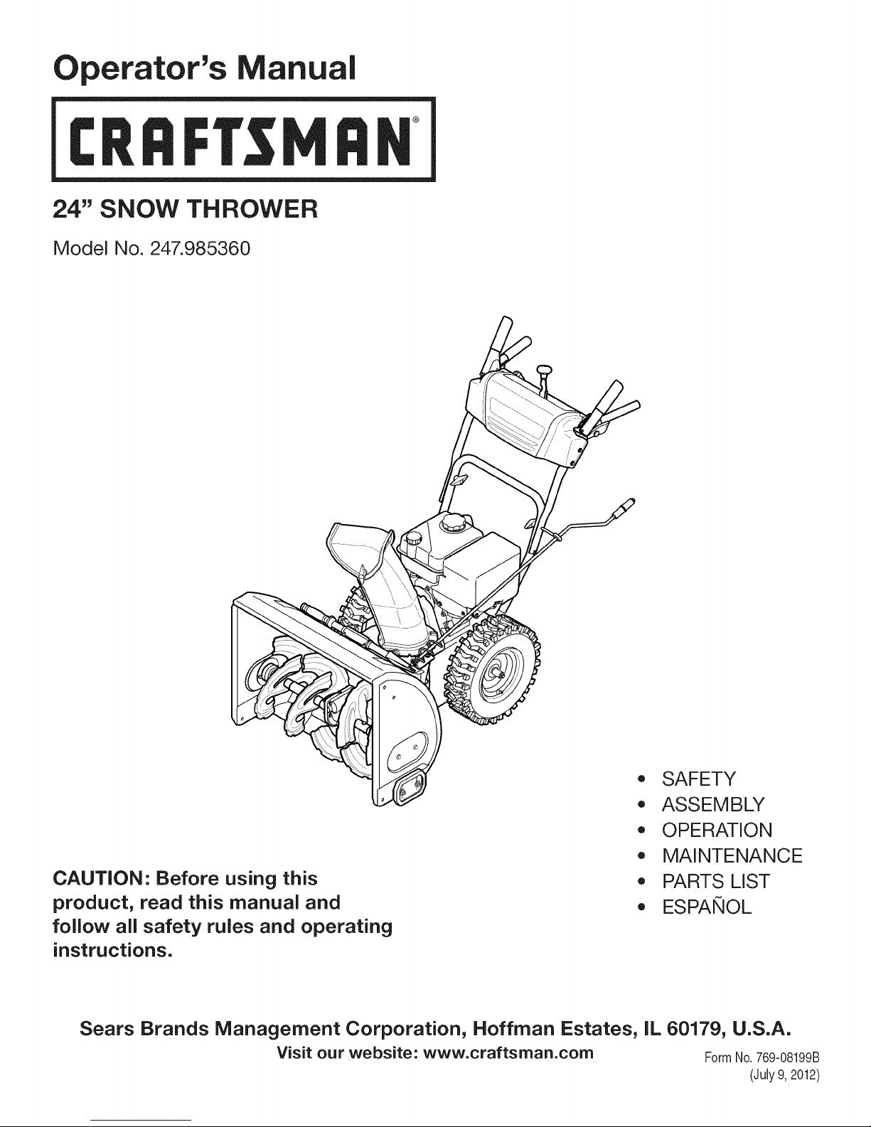
Operator's Manual
CRRFr MRN
24" SNOW THROWER
Model No. 247.985360
CAUTION" Before using this
product, read this manual and
follow all safety rules and operating
instructions.
Sears Brands Management Corporation, Hoffman Estates, IL 60179, U.S.A.
Visit our website: www.craftsman.com FormNo.769-08199B
,, SAFETY
o ASSEMBLY
OPERATION
MAINTENANCE
PARTS LIST
o ESPANOL
(July9,2012)
Page 2
WarrantyStatement.................... Page2
SafeOperationPractices.............. Pages3-6
Assembly......................... Pages8-11
Operation........................ Pages12-15
Service&Maintenance.............. Pages16-23
Off-SeasonStorage................... Page24
Troubleshooting...................... Page25
PartsList......................... Pages26-43
RepairProtectionAgreement............ Page47
Espadol............................. Page48
CRAFTSMANTWOYEARFULLWARRANTY
FORTWOYEARSfromthedateofpurchase,thisproductiswarrantedagainstanydefectsinmaterialorworkmanship.Defectiveproductwill
receivefreerepairorfreereplacementifrepairisunavailable.
Forwarrantycoveragedetails to obtain repairor replacement,visit the website: www.craftsman.com
This warranty covers ONLYdefects in materialandworkmanship. Warrantycoverage does NOTinclude:
• Expendableitemsthatcanwearoutfromnormalusewithinthewarrantyperiod,includingbutnotlimitedto augers,augerpaddles,drift
cutters,skidshoes,shaveplate,shearpins,sparkplug,air cleaner,belts,andoil filter.
• Standardmaintenanceservicing,oilchanges,ortune-ups.
• Tire replacementorrepaircausedbypuncturesfromoutsideobjects,suchasnails,thorns,stumps,or glass.
• Tireor wheelreplacementor repairresultingfromnormalwear,accident,orimproperoperationormaintenance.
Repairsnecessarybecauseof operatorabuse,includingbutnotlimitedtodamagecausedbyover-speedingthe engine,orfromimpacting
objectsthatbendthe frame,augershaft,etc.
• Repairsnecessarybecauseof operatornegligence,includingbutnotlimitedto,electricalandmechanicaldamagecausedbyimproper
storage,failureto usethepropergradeandamountofengineoil,or failureto maintaintheequipmentaccordingto theinstructionscontained
intheoperator'smanual.
• Engine(fuelsystem)cleaningor repairscausedbyfuel determinedto becontaminatedoroxidized(stale).Ingeneral,fuelshouldbeused
within30 daysof itspurchasedate.
Normaldeteriorationandwearof theexteriorfinishes,or productlabelreplacement.
Thiswarrantyisvoidif thisproductiseverusedwhileprovidingcommercialservicesorif rentedtoanotherperson.
Thiswarrantygivesyouspecificlegalrights,andyou mayalsohaveotherrightswhichvaryfromstateto state.
Sears Brands Management Corporation, Hoffman Estates, IL 60179
EngineOilType: 5W-30
EngineOilCapacity: 20ounces
FuelCapacity: 2 Quarts
SparkPlug: F6RTC(951-10292)
SparkPlugGap: .020"to .030"
©SearsBrands,LLC
ModelNumber.................................................................
Serial Number.................................................................
Dateof Purchase .............................................................
Recordthemodelnumber,serialnumber
anddateof purchaseabove
2
Page 3
Thissymbolpointsout importantsafetyinstructionswhich,if not
followed,couldendangerthepersonalsafetyand/orpropertyof
yourselfandothers. Readandfollowallinstructionsin thismanual
beforeattemptingto operatethismachine.Failuretocomplywith
theseinstructionsmayresultin personalinjury.Whenyouseethis
symbol,HEEDITSWARNING!
Thismachinewasbuiltto beoperatedaccordingtothesafeopera-
tionpracticesinthis manual.Aswithanytypeof powerequipment,
carelessnessorerroron thepartofthe operatorcanresultin serious
injury.Thismachineiscapableofamputatingfingers,hands,toes
andfeetandthrowingdebris.Failuretoobservethefollowingsafety
instructionscouldresultin seriousinjuryordeath.
CALIFORNIA PROPOSITION 65
EngineExhaust,someof itsconstituents,andcertainvehicle
componentscontainoremitchemicalsknowntoStateofCalifornia
tocausecancerandbirthdefectsorotherreproductiveharm,
TRAiNiNG
• Read,understand,andfollowall instructionsonthe machineand
in themanual(s)beforeattemptingtoassembleandoperate.
Failuretodo socan resultinseriousinjurytothe operatorand/
orbystanders.Keepthismanualin a safeplaceforfutureand
regularreferenceandfororderingreplacementparts.
• Befamiliarwithall controlsandtheir properoperation.Knowhow
tostopthe machineanddisengagethemquickly.
• Neverallowchildrenunder14yearsofagetooperatethis
machine.Children14andovershouldreadandunderstandthe
instructionsandsafeoperationpracticesin thismanualandon
themachineandbe trainedandsupervisedbyanadult.
Neverallowadultsto operatethismachinewithoutproper
instruction.
• Thrownobjectscancauseseriouspersonalinjury.Planyour
snow-throwingpatterntoavoiddischargeof materialtoward
roads,bystandersandthelike.
Keepbystanders,petsandchildrenat least75feetfromthe
machinewhileitis in operation.Stopmachineifanyoneenters
thearea.
• Exercisecautiontoavoidslippingorfalling,especiallywhen
operatinginreverse.
Your Responsibility--Restrict theuseof thispowermachineto
personswhoread,understandandfollowthewarningsandinstruc-
tionsin thismanualandonthemachine,
SAVE THESE INSTRUCTIONS!
PREPARATION
Thoroughlyinspecttheareawheretheequipmentistobeused.
Removeall doormats,newspapers,sleds,boards,wiresandother
foreignobjects,whichcouldbe trippedoverorthrownbytheauger/
impeller.
• Alwayswearsafetyglassesoreyeshieldsduringoperationand
whileperformingan adjustmentor repairto protectyoureyes.
Thrownobjectswhichricochetcancauseseriousinjurytothe
eyes.
Donot operatewithoutwearingadequatewinteroutergarments.
Donot wearjewelry,longscarvesorotherlooseclothing,which
couldbecomeentangledin movingparts.Wearfootwearwhich
willimprovefootingonslipperysurfaces.
Usea groundedthree-wireextensioncordandreceptacleforall
machineswithelectricstartengines.
Disengageall controlleversbeforestartingthe engine.
Adjustcollectorhousingheighttocleargravelorcrushedrock
surfaces.
• Neverattemptto makeanyadjustmentswhileengineis running,
exceptwherespecificallyrecommendedintheoperator'smanual.
Letengineandmachineadjustto outdoortemperaturebefore
startingtoclearsnow.
3
Page 4
SafeHandling of Gasoline
Toavoidpersonalinjuryor propertydamageuseextremecarein
handlinggasoline.Gasolineisextremelyflammableandthevaporsare
explosive.Seriouspersonalinjurycanoccurwhengasolineis spilled
onyourselforyourclotheswhichcan ignite. Washyour skinand
changeclothesimmediately.
• Useonlyan approvedgasolinecontainer.
• Extinguishallcigarettes,cigars,pipesandothersourcesof
ignition.
• Neverfuel machineindoors.
• Neverremovegascapor addfuelwhiletheengineishotor
running.
• Allowenginetocoolat leasttwo minutesbeforerefueling.
• Neveroverfillfueltank.Fill tankto nomorethan1/2inchbelow
bottomoffillerneckto providespaceforfuelexpansion.
• Replacegasolinecapandtightensecurely.
• Ifgasolineisspilled,wipeitoff theengineandequipment.Move
machinetoanotherarea.Wait5 minutesbeforestartingthe
engine.
• Neverstorethe machineorfuelcontainerinsidewherethereisan
openflame,sparkor pilotlight(e.g.furnace,waterheater,space
heater,clothesdryeretc.).
• Allowmachinetocoolat least5 minutesbeforestoring.
• Neverfill containersinsidea vehicleor ona truckor trailerbed
witha plasticliner.Alwaysplacecontainersonthegroundaway
fromyourvehiclebeforefilling.
• If possible,removegas-poweredequipmentfromthe truckor
trailerandrefuelitonthe ground.Ifthisisnot possible,thenrefuel
suchequipmenton a trailerwitha portablecontainer,ratherthan
froma gasolinedispensernozzle.
• Keepthe nozzlein contactwiththe rimofthefueltankor
containeropeningatalltimesuntilfuelingis complete.Donotuse
a nozzlelock-opendevice.
OPERATION
• Do notputhandsorfeetnear rotatingparts,in the auger/impeller
housingorchuteassembly.Contactwiththerotatingpartscan
amputatehandsandfeet.
• Theauger/impellercontrolleveris a safetydevice.Neverbypass
itsoperation.Doingsomakesthe machineunsafeandmaycause
personalinjury.
• Thecontrolleversmustoperateeasilyinbothdirectionsand
automaticallyreturntothe disengagedpositionwhenreleased.
• Neveroperatewithamissingordamagedchuteassembly.Keep
all safetydevicesinplaceandworking.
• Neverrunanengineindoorsorina poorlyventilatedarea.Engine
exhaustcontainscarbonmonoxide,anodorlessanddeadlygas.
• Do notoperatemachinewhileundertheinfluenceofalcoholor
drugs.
• Mufflerandenginebecomehotandcancausea burn.Donot
touch.Keepchildrenaway.
• Exerciseextremecautionwhenoperatingonorcrossinggravel
surfaces.Stayalertforhiddenhazardsortraffic.
Exercisecautionwhenchangingdirectionandwhileoperatingon
slopes.Do notoperateon steepslopes.
Planyoursnow-throwingpatternto avoiddischargetowards
windows,walls,carsetc.Thus,avoidingpossibleproperty
damageorpersonalinjurycausedby a ricochet.
Neverdirectdischargeat children,bystandersand petsorallow
anyoneinfrontof themachine.
Donot overloadmachinecapacitybyattemptingtoclearsnowat
toofastof a rate.
Neveroperatethismachinewithoutgoodvisibilityorlight.Always
be sureofyourfootingandkeepafirmholdon thehandles.Walk,
neverrun.
Disengagepowerto theauger/impellerwhentransportingor not
in use.
Neveroperatemachineathightransportspeedson slippery
surfaces.Lookdownand behindand usecarewhenbackingup.
Ifthemachineshouldstartto vibrateabnormally,stoptheengine,
disconnectthesparkplugwireandgroundit againsttheengine.
Inspectthoroughlyfor damage.Repairanydamagebefore
startingandoperating.
Disengageall controlleversandstopenginebeforeyouleave
theoperatingposition(behindthehandles).Waituntiltheauger/
impellercomestoa completestopbeforeuncloggingthechute
assembly,makingany adjustments,or inspections.
Neverputyourhandinthe dischargeorcollectoropenings.Do
notunclogchuteassemblywhileengineis running.Shutoff
engineand remainbehindhandlesuntilallmovingpartshave
stoppedbeforeunclogging.
Useonlyattachmentsandaccessoriesapprovedbythemanufac-
turer(e.g.wheelweights,tirechains,cabsetc.). Forinformation
concerningtheseitems,call1-800-469-4663.
Whenstartingengine,pullcord slowlyuntilresistanceis felt,then
pull rapidly.Rapidretractionof startercord(kickback)willpull
handandarmtowardenginefasterthanyoucanlet go.Broken
bones,fractures,bruisesorsprainscouldresult.
Ifsituationsoccurwhichare notcoveredinthis manual,usecare
andgoodjudgment.
Toorderpartsor scheduleserviceforthisproduct,call 1-800-
469-4663.
CLEARING A CLOGGED DISCHARGE CHUTE
Handcontactwiththe rotatingimpellerinsidethedischargechute
is themostcommoncauseof injuryassociatedwithsnowthrowers.
Neveruseyourhandto cleanoutthedischargechute.
Toclear thechute:
1. SHUTTHEENGINEOFF!
2. Wait 10secondstobe surethe impellerbladeshavestopped
rotating.
3. Alwaysusea clean-outtool,not yourhands.
4
Page 5
MAINTENANCE & STORAGE
• Nevertamperwithsafetydevices.Checktheirproperoperation
regularly.Refertothemaintenanceandadjustmentsectionsof
thismanual.
• Beforecleaning,repairing,or inspectingmachinedisengageall
controlleversandstoptheengine.Waituntilthe auger/impeller
cometoa completestop.Disconnectthe sparkplugwireand
groundagainsttheengineto preventunintendedstarting.
Checkboltsand screwsforpropertightnessatfrequentintervals
tokeepthemachineinsafeworkingcondition.Also,visually
inspectmachineforanydamage.
Donotchangetheenginegovernorsettingor over-speedthe
engine.Thegovernorcontrolsthe maximumsafeoperatingspeed
ofthe engine.
Snowthrowershaveplatesandskidshoesaresubjecttowear
anddamage.Foryoursafetyprotection,frequentlycheckall
componentsand replacewithoriginalequipmentmanufacturer's
(OEM)partsonlyaslistedinthe Partspagesof thisoperator's
manual.Useofpartswhichdonot meettheoriginalequipment
specificationsmayleadto improperperformanceandcompro-
misesafety!
Checkcontrolleversperiodicallytoverifytheyengageanddisen-
gageproperlyandadjust,ifnecessary.Refertotheadjustment
sectioninthisoperator'smanualfor instructions.
Maintainor replacesafetyandinstructionlabels,asnecessary.
Observeproperdisposallawsand regulationsforgas,oil,etc. to
protecttheenvironment.
Priorto storing,runmachineafew minutestoclearsnowfrom
machineand preventfreezeupof auger/impeller.
Neverstorethemachineorfuel containerinsidewherethereisan
openflame,sparkorpilot lightsuchasa waterheater,furnace,
clothesdryeretc.
Alwaysrefertothe operator'smanualforproperinstructionson
off-seasonstorage.
Checkfuelline,tank, cap,andfittingsfrequentlyforcracksor
leaks.Replaceif necessary.
Donotcrankenginewithsparkplugremoved.
AccordingtotheConsumerProductsSafetyCommission(CPSC)
andtheU.S.EnvironmentalProtectionAgency(EPA),thisproduct
hasan AverageUsefulLifeof seven(7)years,or 60 hoursof
operation.Attheendof theAverageUsefulLifehavethemachine
inspectedannuallybyanauthorizedservicedealertoensurethat
allmechanicalandsafetysystemsareworkingproperlyand not
wornexcessively.Failuretodo socan resultinaccidents,injuries
ordeath.
DO NOT MODIFY ENGINE
Toavoidseriousinjuryor death,do notmodifyengineinany way.
Tamperingwiththegovernorsettingcanleadtoa runawayengineand
causeitto operateat unsafespeeds.Nevertamperwithfactorysetting
ofenginegovernor.
NOTICE REGARDING EMiSSiONS
EngineswhicharecertifiedtocomplywithCaliforniaandfederal
EPAemissionregulationsforSORE(SmallOff RoadEquipment)are
certifiedto operateonregularunleadedgasoline,andmayinclude
thefollowingemissioncontrolsystems:EngineModification(EM),
OxidizingCatalyst(OC),SecondaryAirInjection(SAI)and ThreeWay
Catalyst(TWO)if so equipped.
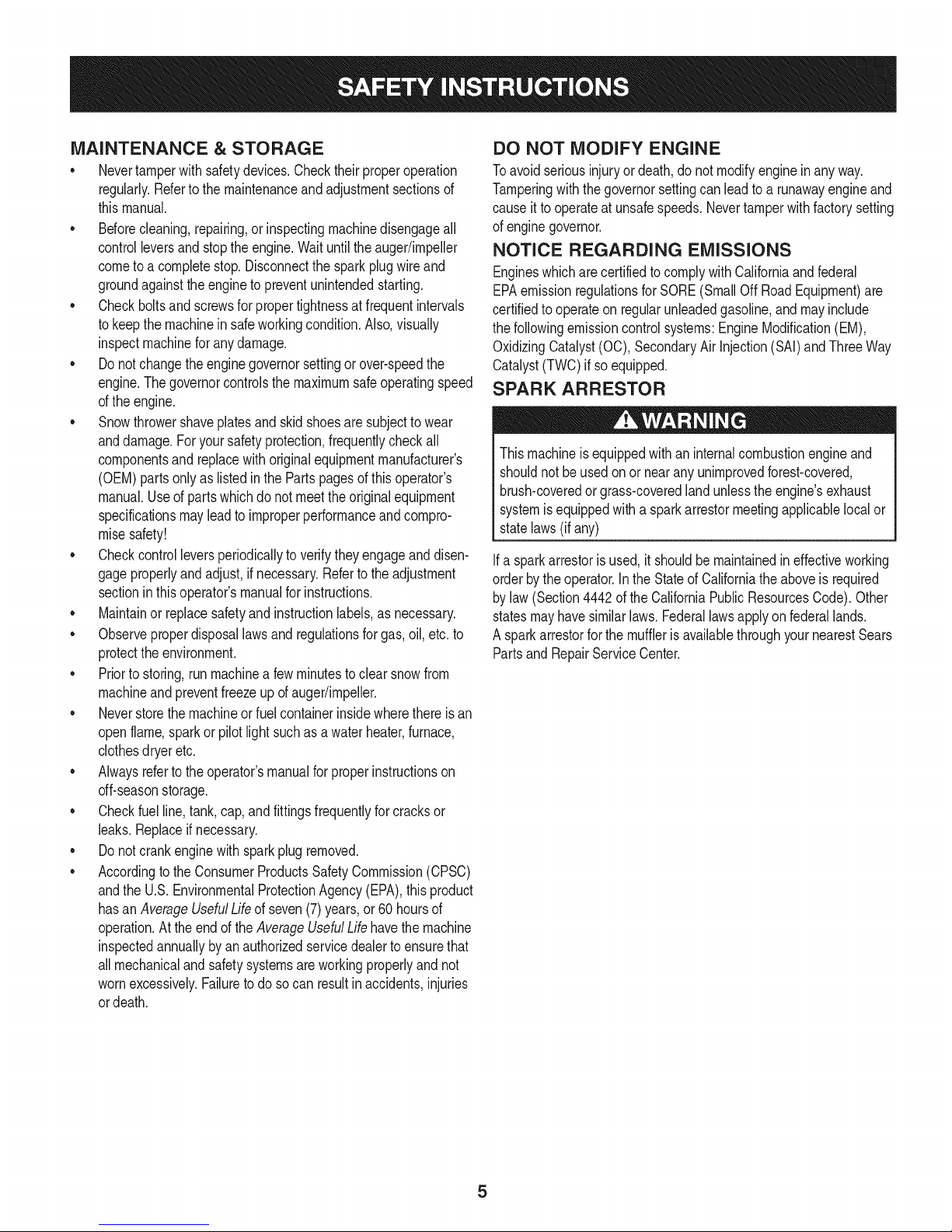
SPARK ARRESTOR
Thismachineisequippedwithaninternalcombustionengineand
shouldnotbe usedonornearanyunimprovedforest-covered,
brush-coveredorgrass-coveredlandunlessthe engine'sexhaust
systemisequippedwitha sparkarrestormeetingapplicablelocalor
statelaws(if any)
Ifa sparkarrestorisused,itshouldbe maintainedin effectiveworking
orderbytheoperator.Inthe StateofCaliforniatheaboveis required
bylaw (Section4442oftheCaliforniaPublicResourcesCode).Other
statesmayhavesimilarlaws. Federallawsapplyonfederallands.
A sparkarrestorfor the mufflerisavailablethroughyournearestSears
PartsandRepairServiceCenter.
Page 6
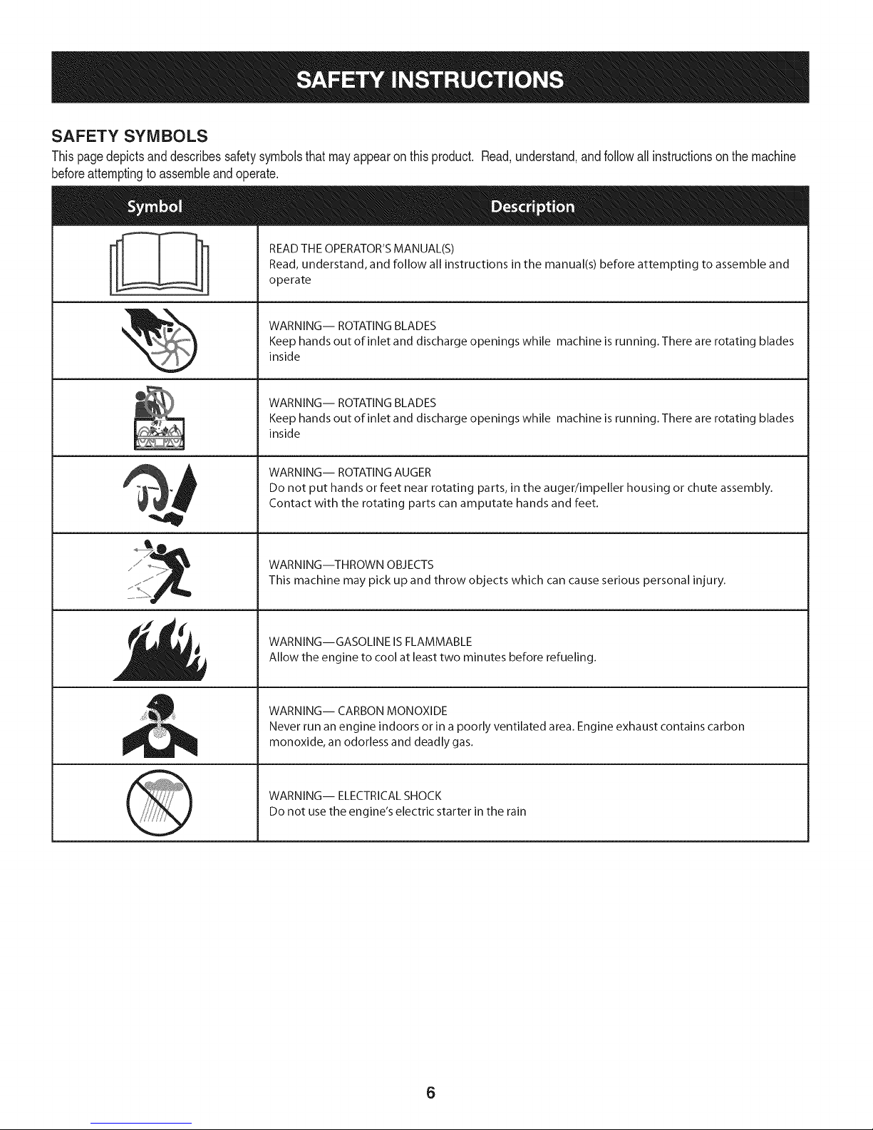
SAFETY SYMBOLS
Thispagedepictsanddescribessafetysymbolsthatmayappearonthisproduct. Read,understand,andfollowall instructionson themachine
beforeattemptingto assembleandoperate.
READ THE OPERATOR'S MANUAL(S)
i
. +
i
Read, understand, and follow all instructions in the manual(s) before attempting to assemble and
operate
WARNING-- ROTATING BLADES
Keep hands out of inlet and discharge openings while machine is running. There are rotating blades
inside
WARNING-- ROTATING BLADES
Keep hands out of inlet and discharge openings while machine is running. There are rotating blades
inside
WARNING-- ROTATING AUGER
Do not put hands or feet near rotating parts, in the auger/impeller housing or chute assembly.
Contact with the rotating parts can amputate hands and feet.
"JIp
WARNING--THROWN OBJECTS
This machine may pick up and throw objects which can cause serious personal injury.
WARNING--GASOLINE ISFLAMMABLE
Allow the engine to cool at least two minutes before refueling.
WARNING-- CARBON MONOXIDE
Never run an engine indoors or in a poorly ventilated area. Engine exhaust contains carbon
monoxide, an odorless and deadly gas+
WARNING-- ELECTRICAL SHOCK
Do not use the engine's electric starter in the rain
6
Page 7

Thispageleftintentionallyblank.
7
Page 8
NOTE:Referencesto rightorleft sideofthesnowthrowerare
determinedfrombehindtheunit intheoperatingposition(standing
directlybehindthesnowthrower,facingthe handlepanel).
REMOVING FROM CARTON
1. Cutthecornersof thecartonandlaythe sidesflaton the ground.
Removeanddiscardallpackinginserts.
2. Movethesnowthrowerout of thecarton.
3. Makecertainthecartonhas beencompletelyemptiedbefore
discardingit.
ASSEMBLY
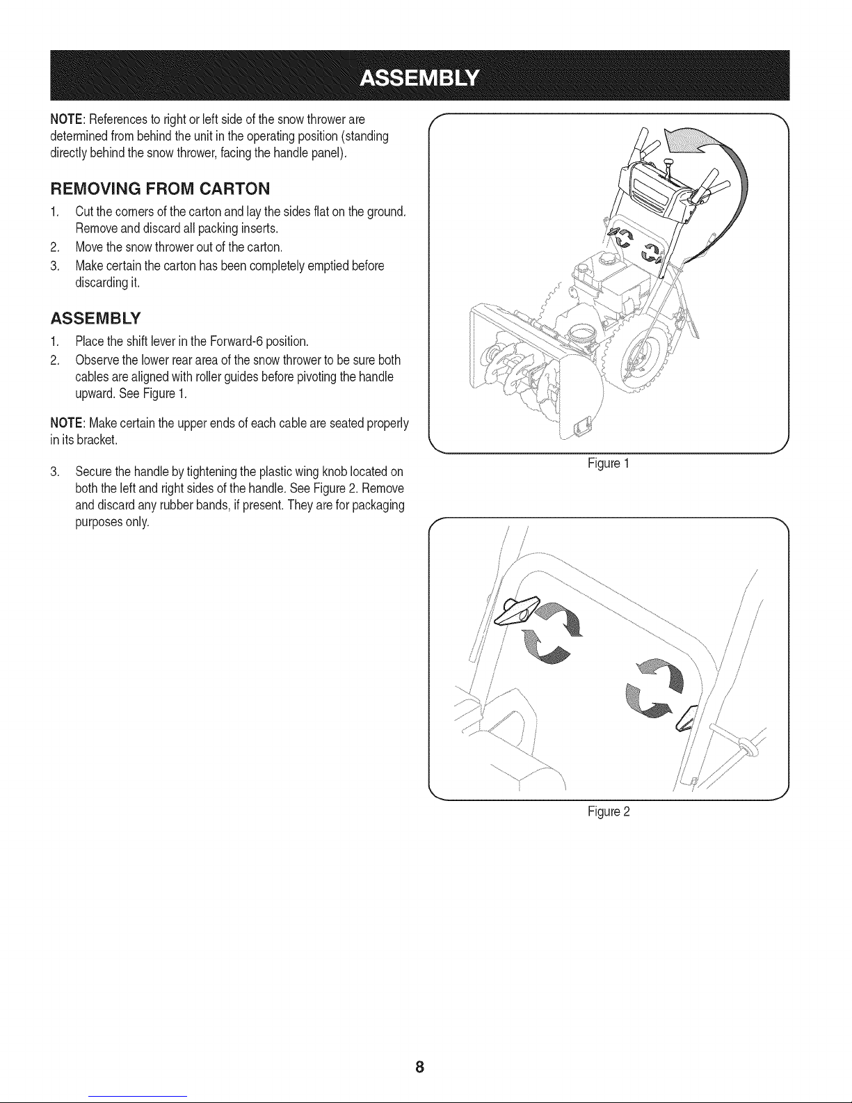
1. Placethe shiftleverin theForward-6position.
2. Observethe lowerrearareaofthe snowthrowertobesureboth
cablesarealignedwith rollerguidesbeforepivotingthe handle
upward.See Figure1.
NOTE:Makecertainthe upperendsofeachcableare seatedproperly
in itsbracket.
.
Securethehandlebytighteningtheplasticwingknoblocatedon
boththe leftand rightsidesofthe handle.SeeFigure2.Remove
anddiscardanyrubberbands,if present.Theyareforpackaging
purposesonly.
\
Figure1
f
Figure2
8
Page 9
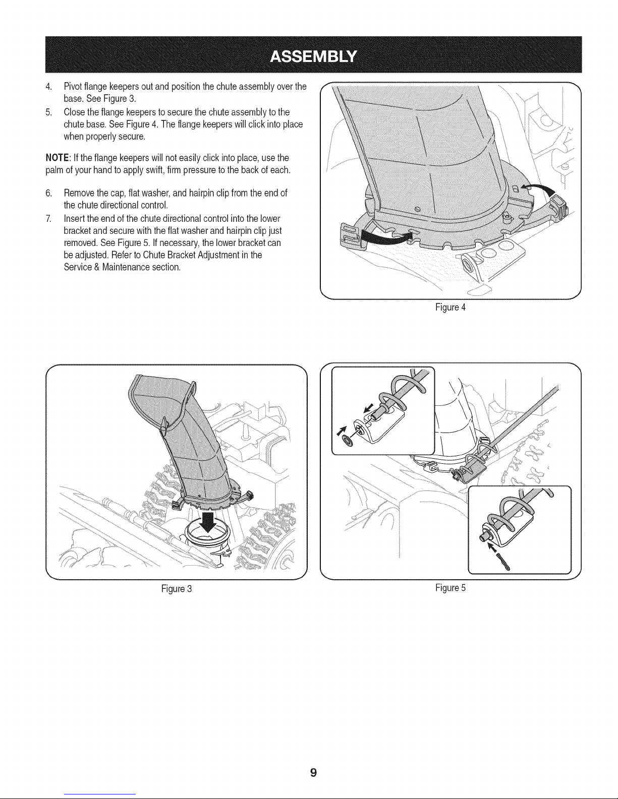
4. Pivotflangekeepersoutand positionthechuteassemblyoverthe
base.SeeFigure3.
5. Closetheflangekeepersto securethechuteassemblytothe
chutebase.SeeFigure4.Theflangekeeperswillclickinto place
whenproperlysecure.
NOTE:Ifthe flangekeeperswillnoteasilyclickintoplace,usethe
palmof yourhandtoapplyswift,firmpressuretothebackof each.
.
Removethecap,flatwasher,andhairpinclip fromtheendof
thechutedirectionalcontrol.
7.
Insertthe endofthechutedirectionalcontrolintothelower
bracketandsecurewiththe flatwasherandhairpinclipjust
removed.See Figure5.If necessary,thelowerbracketcan
beadjusted.Referto ChuteBracketAdjustmentinthe
Service& Maintenancesection.
f F
Figure4
Figure3
\
Figure5
J
9
Page 10
SET-UP
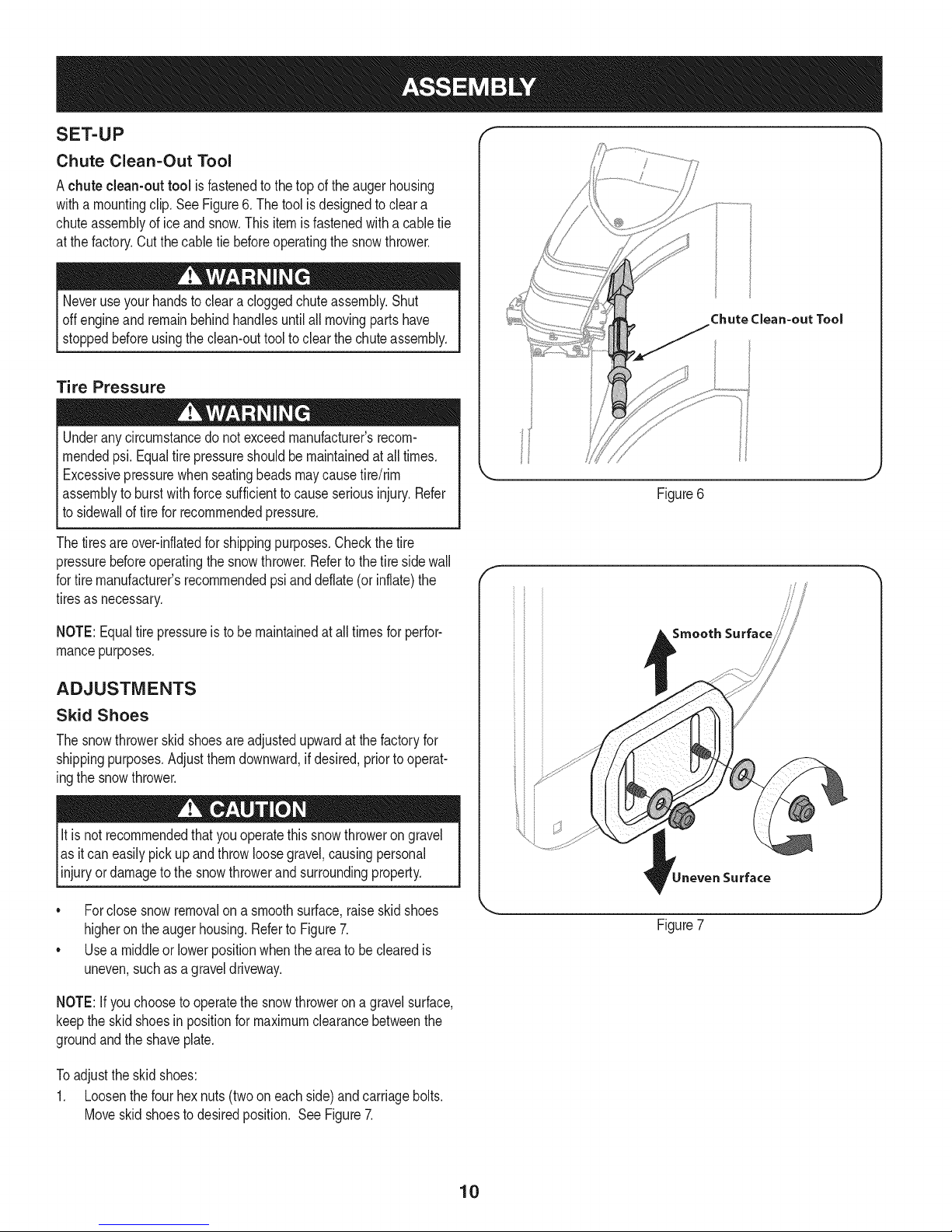
Chute Clean-Out Tool
Achute clean-out tool isfastenedtothe topofthe augerhousing
witha mountingclip.SeeFigure6.The toolisdesignedtocleara
chuteassemblyofice andsnow.Thisitemisfastenedwithacabletie
atthe factory.Cutthecabletiebeforeoperatingthesnowthrower.
Neveruseyour handsto cleara cloggedchuteassembly.Shut
offengineand remainbehindhandlesuntilall movingpartshave
stoppedbeforeusingtheclean-outtooltoclear thechuteassembly.
Tire Pressure
Underanycircumstancedo notexceedmanufacturer'srecom-
mendedpsi.Equaltirepressureshouldbemaintainedat all times.
Excessivepressurewhenseatingbeadsmaycausetire/rim
assemblytoburstwithforcesufficienttocauseseriousinjury.Refer
tosidewallof tirefor recommendedpressure.
Thetiresareover-inflatedforshippingpurposes.Checkthetire
pressurebeforeoperatingthesnowthrower.Referto thetiresidewall
fortiremanufacturer'srecommendedpsianddeflate(orinflate)the
tiresasnecessary.
Chute Clean=out Tool
Figure6
f
NOTE:Equaltire pressureis tobe maintainedat alltimesforperfor-
mancepurposes.
ADJUSTMENTS
Skid Shoes
Thesnowthrowerskidshoesareadjustedupwardatthefactoryfor
shippingpurposes.Adjustthemdownward,ifdesired,priortooperat-
ingthesnowthrower.
It isnotrecommendedthatyouoperatethis snowthrowerongravel
asit caneasilypickup andthrowloosegravel,causingpersonal
njuryordamageto thesnowthrowerandsurroundng property.
• Forclosesnowremovalona smoothsurface,raiseskidshoes
higherontheaugerhousing.Referto Figure7.
• Usea middleorlowerpositionwhentheareatobe clearedis
uneven,suchasa graveldriveway.
NOTE:If youchooseto operatethesnowthrowerona gravelsurface,
keepthe skidshoesin positionfor maximumclearancebetweenthe
groundandtheshaveplate.
Toadjustthe skidshoes:
1. Loosenthefourhexnuts(twooneachside)andcarriagebolts.
Moveskidshoestodesiredposition. SeeFigure7.
Smooth Surface
Surface
Figure7
10
Page 11
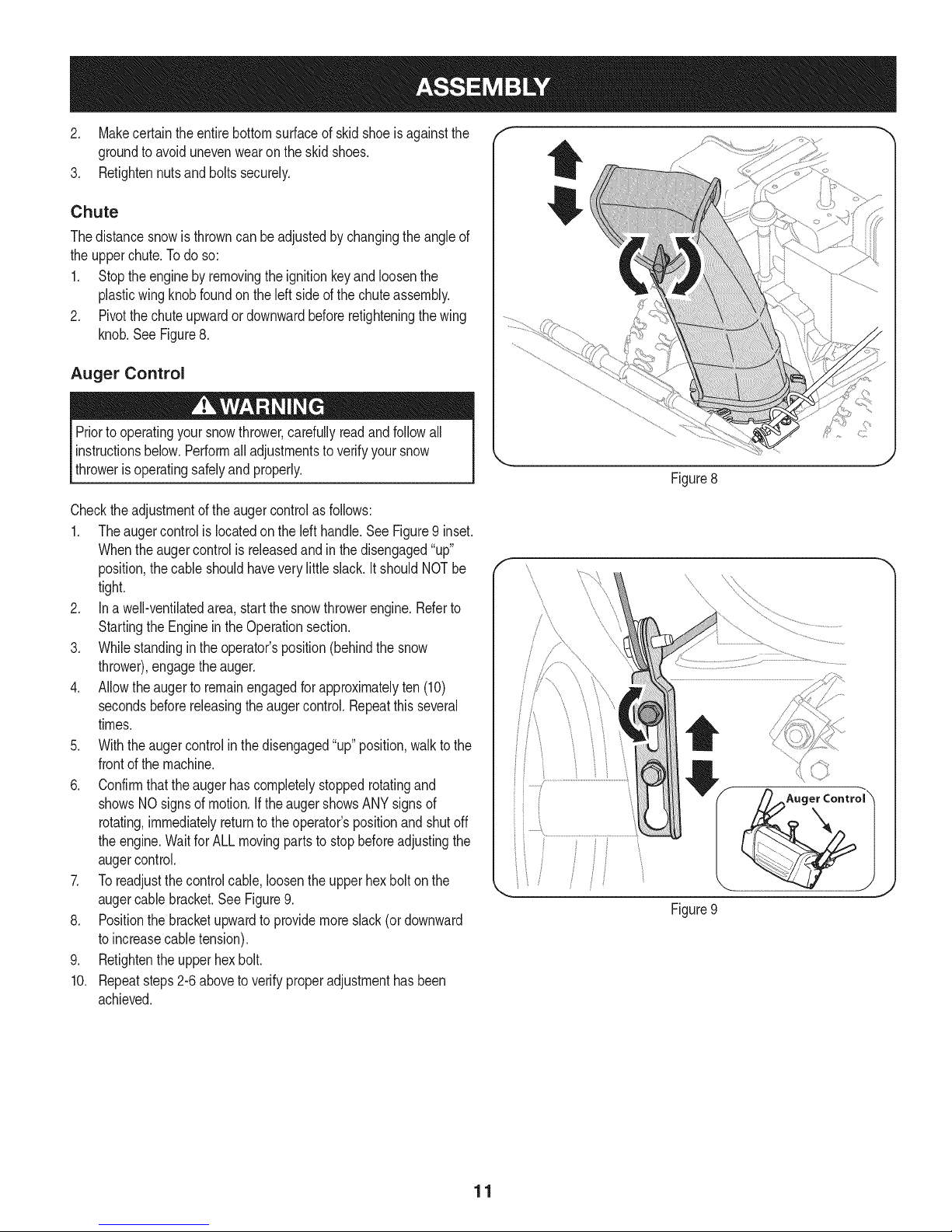
2, Makecertaintheentirebottomsurfaceof skidshoeis againstthe f
groundtoavoidunevenwearontheskidshoes, ....
3. Retightennutsandboltssecurely.
Chute
Thedistancesnowisthrowncan beadjustedbychangingthe angleof
theupperchute.Todo so:
1. Stoptheenginebyremovingthe ignitionkeyandloosenthe
plasticwingknobfoundontheleft sideof thechuteassembly.
2. Pivotthechuteupwardordownwardbeforeretighteningthewing
knob.See Figure8.
Auger Control
Priortooperatingyoursnowthrower,carefullyreadandfollowall
instructionsbelow.Performalladjustmentstoverifyyour snow
throwerisoperatingsafelyandproperly.
Checktheadjustmentoftheaugercontrolas follows:
1. Theaugercontrolislocatedontheleft handle.SeeFigure9 inset.
Whentheaugercontrolis releasedandin thedisengaged"up"
position,thecableshouldhaveverylittleslack.ItshouldNOTbe
tight.
2. Ina well-ventibtedarea,startthe snowthrowerengine.Referto
StartingtheEngineinthe Operationsection.
3. Whilestandinginthe operator'sposition(behindthe snow
thrower),engagethe auger.
4. Allowtheaugertoremainengagedforapproximatelyten (10)
secondsbeforereleasingthe augercontrol.Repeatthisseveral
times.
5. Withtheaugercontrolin thedisengaged"up" position,walktothe
frontofthe machine.
6. Confirmthatthe augerhas completelystoppedrotatingand
showsNOsignsofmotion.If theaugershowsANYsignsof
rotating,immediatelyreturntothe operator'spositionandshutoff
theengine.WaitforALLmovingpartsto stopbeforeadjustingthe
augercontrol.
7. Toreadjustthecontrolcable,loosentheupperhexbolt onthe
augercablebracket.SeeFigure9.
8. Positionthe bracketupwardto providemoreslack(ordownward
toincreasecabletension).
9. Retightentheupperhex bolt.
10. Repeatsteps2-6aboveto verifyproperadjustmenthasbeen
achieved.
\
ii
Figure8
Figure9
11
Page 12
f
Drive Control
Gas Cap
\
Shift Lever
J
Auger Control
ChuteAssembly
Auger
Housing
\,
OilFill
\\\\
\\
\
_jjjj Chute Directional Control
Mumer RecoilStarter
ndle
\
\
\
Key
Augers
Skid Shoes
Figure10
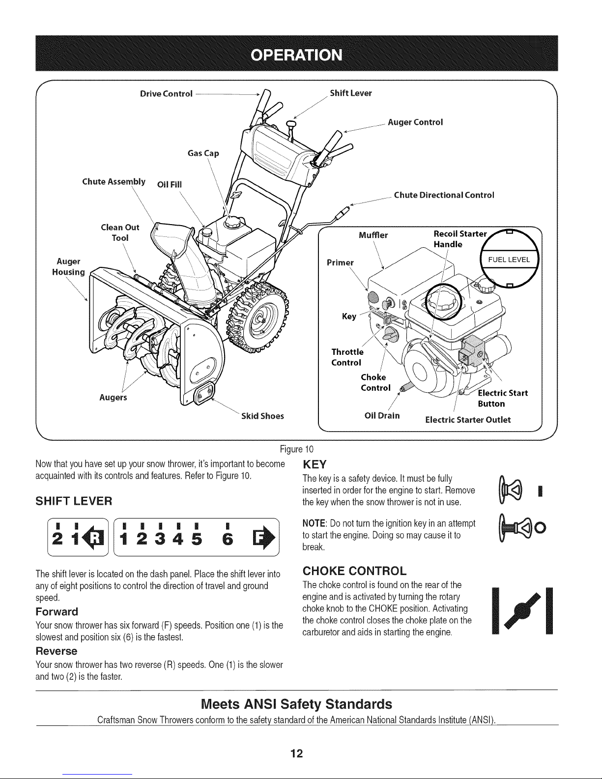
Nowthat youhavesetup yoursnowthrower,it'simportanttobecome KEY
acquaintedwith itscontrolsandfeatures,RefertoFigure10, Thekeyisa safetydevice.It mustbefully
insertedinorderforthe enginetostart, Remove
SHIFT LEVER thekeywhenthesnowthroweris notin use,
J
1 2345 6
Theshiftleveris locatedonthedashpanel.Placetheshiftleverinto
anyof eightpositionstocontrolthedirectionoftravelandground
speed.
Forward
Yoursnowthrowerhassixforward(F) speeds.Positionone(1)is the
slowestandpositionsix(6) isthefastest.
Reverse
Yoursnowthrowerhastwo reverse(R)speeds.One(1)is theslower
andtwo(2) isthefaster.
Meets ANSi Safety Standards
CraftsmanSnowThrowersconformtothe safetystandardof theAmericanNationalStandardsInstitute(ANSI).
'
NOTE:Donotturntheignitionkeyinan attempt
to startthe engine,Doingsomaycauseitto
break.
CHOKE CONTROL
Thechokecontrolis foundontherearof the
engineand isactivatedbyturningthe rotary
chokeknobto theCHOKEposition.Activating
thechokecontrolclosesthechokeplateon the
carburetorandaidsinstartingtheengine.
12
Page 13
THROTTLE CONTROL
aiW'
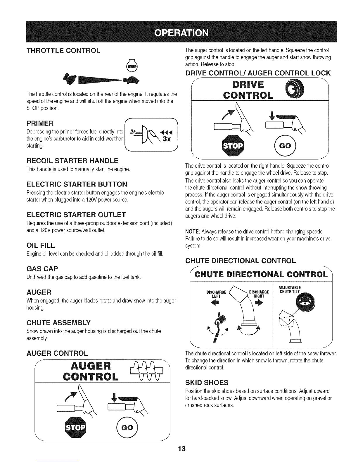
Theaugercontrolis locatedon thelefthandle.Squeezethe control
gripagainstthehandleto engagetheaugerand startsnowthrowing
action.Releaseto stop.
DRIVE CONTROL/AUGER CONTROL LOCK
J DRIVE
Thethrottlecontrolis locatedon the rearoftheengine.It regulatesthe
speedof theengineandwillshutoff the enginewhenmovedintothe
STOPposition.
Depressingthe primerforcesfueldirectlyinto ___144
theengine'scarburet°rt° aid inc°'dweather k _"_'-_ 3" Jstarting.
RECOIL STARTER HANDLE
Thishandleisusedto manuallystarttheengine.
ELECTRIC STARTER BUTTON
Pressingtheelectricstarterbuttonengagestheengine'selectric
starterwhenpluggedintoa 120Vpowersource.
ELECTRIC STARTER OUTLET
Requirestheuseof athree-prongoutdoorextensioncord(included)
anda 120Vpowersource/walloutlet.
OIL FILL
Engineoil levelcanbecheckedandoiladdedthroughtheoil fill.
GAS CAP
Unthreadthegascap toaddgasolinetothefuel tank.
AUGER
Whenengaged,theaugerbladesrotateanddrawsnowintothe auger
housing.
r 1
CONTROL
Thedrivecontrolis locatedon the righthandle.Squeezethecontrol
gripagainstthehandleto engagethewheeldrive.Releasetostop.
Thedrivecontrolalsolockstheaugercontrolso youcanoperate
thechutedirectionalcontrolwithoutinterruptingthesnowthrowing
process.If the augercontrolisengagedsimultaneouslywiththedrive
control,the operatorcanreleasetheaugercontrol(onthe lefthandle)
andtheaugerswillremainengaged.Releaseboth controlstostopthe
augersandwheeldrive.
NOTE:Alwaysreleasethedrivecontrolbeforechangingspeeds.
Failureto doso willresultinincreasedwearon yourmachine'sdrive
system.
CHUTE DIRECTIONAL CONTROL
/_CCHUTE DIRECTIONAL CONTROL
ADJUSTABLE
DISCHARGE DISCHARGE
LEFT
CHUTETILT
CHUTE ASSEMBLY
Snowdrawnintotheaugerhousingisdischargedoutthechute
assembly.
AUGER CONTROL
,....
#
_ J
The chute directional control is located on left side of the snow thrower.
Tochange the direction inwhich snow is thrown, rotate the chute
directionalcontrol.
SKID SHOES
Positiontheskidshoesbasedonsurfaceconditions.Adjustupward
forhard-packedsnow.Adjustdownwardwhenoperatingon gravelor
crushedrocksurfaces.
13
Page 14
CLEAN-OUT TOOL
Neveruseyourhandstocleara cloggedchuteassembly.Shut
off engineandremainbehindhandlesuntilall movingpartshave
stoppedbeforeusingtheclean-outtooltoclear thechuteassembly.
Thechuteclean-outtoolisconvenientlyfastenedtothe rearofthe
augerhousingwitha mountingclip. Shouldsnowandice become
lodgedin thechuteassemblyduringoperation,proceedasfollowsto
safelycleanthechuteassemblyandchuteopening:
1. Releaseboththe AugerControlandthe DriveControl.
2. Stopthe engineby removingthe ignitionkey.
3. Removetheclean-outtoolfromtheclip whichsecuresittothe
rearofthe augerhousing.
4. Usetheshovel-shapedendof theclean-outtool to dislodgeand
scoopanysnowand icewhichhasformedin andnearthechute
assembly.
5. Refastenthe clean-outtool tothemountingclipontherearof the
augerhousing,reinserttheignitionkeyandstartthesnow
thrower'sengine.
6. Whilestandinginthe operator'sposition(behindthesnow
thrower),engagethe augercontrolforafewsecondstoclearany
remainingsnowandice fromthechuteassembly.
BEFORE STARTING ENGINE
Read,understand,andfollowall instructionsandwarningsonthe
machineand inthismanualbeforeoperating.
Oil
Theunit wasshippedwith oil inthe engine.Checkoillevelbefore
eachoperationtoensureadequateoilinthe engine.Forfurther
instructions,refertothe stepsonpage16.
NOTE:Besuretochecktheengineon a levelsurfacewiththeengine
stopped.
1. Removetheoil fillercap/dipstickandwipethedipstickclean.
2. insertthecap/dipstickintotheoilfillerneck,butdo NOTscrewit
in.
3. Removetheoil fillercap/dipstick,ifthe levelislow,slowlyadd
oil (5%30, witha minimumclassificationof SF/SG)untiloillevel
registersbetweenhigh(H) andlow(L).
NOTE:Do notoverfill.Overfillingwithoil mayresultinenginesmoking,
hardstartingorsparkplugfouling.
4. Replaceandtightencap/dipstickfirmlybeforestartingengine.
Gasoline
Useautomotivegasoline(unleadedor lowleadedto minimizecombus-
tionchamberdeposits)witha minimumof87octane.Gasolinewith
upto 10%ethanolor 15%MTBE(MethylTertiaryButylEther)canbe
used.Neveruseanoil/gasolinemixtureor dirtygasoline.Avoidgetting
dirt,dust,or waterinthefuel tank.DONOTuse E85gasoline.
• Refuelina well-ventilatedareawiththe enginestopped.Donot
smokeorallowflamesor sparksinthe areawheretheengineis
refueledor wheregasolineisstored.
• Donotoverfillthefueltank.After refueling,makesurethetank
capis closedproperlyandsecurely.
• Becarefulnotto spillfuelwhenrefueling.Spilledfuelorfuelvapor
mayignite,ifanyfuelisspilled,makesuretheareaisdrybefore
startingthe engine.
• Avoidrepeatedorprolongedcontactwithskinor breathingof
)or.
Useextremecarewhenhandlinggasoline.Gasolineisextremely
flammableandthevaporsare explosive.Neverfuelthemachine
indoorsorwhilethe engineishotor running.Extinguishcigarettes,
cigars,pipesandothersourcesof ignition.
1. Cleanaroundfuelfillbeforeremovingcap to fuel.
2. A fuel levelindicatorislocatedinthefueltank. SeeFigure10
inset.Becarefulnottooverfill.Filltank untilfuel reachesthe fuel
levelindicatortoallowspacefor fuel expansion.
STARTING THE ENGINE
Alwayskeephandsandfeetclearof movingparts.Donot usea
pressurizedstartingfluid.Vaporsareflammable.
NOTE:Allowtheengineto warmupfora fewminutesafter starting.
Theenginewill notdevelopfull poweruntilit reachesoperating
temperatures.
1. Makecertainboththe augercontrolanddrivecontrolareinthe
disengaged(released)position.
2. insertkeyintoslot. Makesureitsnapsintoplace.Donotattempt
toturn thekey.
NOTE:Theenginecannotstartwithoutthekeyfullyinsertedintothe
ignitionswitch.
Electric Starter
Theoptionalelectricstarterisequippedwitha groundedthree-wire
powercordand plug,andisdesignedtooperateon120voltAC
householdcurrent.Itmustbe usedwithaproperlygroundedthree-
prongreceptacleat all timestoavoidthepossibilityofelectricshock.
Followall instructionscarefullypriorto operatingtheelectricstarter.
DONOTuseelectricstarterinthe rain.
Determinethatyourhome'swiringisa three-wiregroundedsystem.
Aska licensedelectricianifyouarenotcertain.
Ifyou haveagroundedthree-prongreceptacle,proceedasfollows.
Ifyou donothavethe properhousewiring,DONOTusetheelectric
starterunderanyconditions.
1. Plugtheextensioncord intotheoutletlocatedon theengine's
surface.Plugtheotherendof extensioncord intoa three-prong
120-volt,grounded,ACoutletina well-ventilatedarea.
14
Page 15
2. Movethrottlecontrolto FAST(rabbit)_T position.
3. Movechoketothe CHOKEIJl position(coldenginestart).If
engineiswarm,placechokein RUNposition.
4. Pushprimerthree(3)times,makingsuretocoverventholein
primerbulbwhen pushing.If engineiswarm,pushprimeronly
once.Alwayscoverventholewhenpushing.Coolweathermay
requireprimingtobe repeated.
5. Pushstarterbuttontostart engine.Oncetheenginestarts,im-
mediatelyreleasestarterbutton.Electricstarterisequippedwith
thermaloverloadprotection;systemwilltemporarilyshut-downto
allowstartertocool ifelectricstarterbecomesoverloaded.
6. Astheenginewarms,slowlyrotatethechokecontrolto RUN
position.Ifthe enginefalters,restartengineandrunwithchoke
athalf-chokepositionfora shortperiodoftime,andthenslowly
rotatethechokeinto RUNposition.
7. Afterengineisrunning,disconnectpowercordfromelectric
starter.Whendisconnecting,alwaysunplugtheendatthewall
outletbeforeunpluggingtheoppositeendfromtheengine.
Recoil Starter
Donotpullthestarterhandlewhilethe enginerunning.
1. Movethrottlecontrolto FAST(rabbit)_J_ position.
2. Movechoketothe CHOKEI,'_¢1position(coldenginestart).If
engineiswarm,placechokein RUNposition.
3. Pushprimerthree(3)times,makingsuretocoverventholewhen
pushing.Ifengineiswarm,pushprimeronlyonce.Alwayscover
ventholewhenpushing.Coolweathermayrequireprimingtobe
repeated.
4. Pullgentlyonthe starterhandleuntilitbeginstoresist,then
pullquicklyandforcefullytoovercomethe compression.Do
notreleasethehandleandallowitto snapback.Returnrope
SLOWLYto originalposition.Ifrequired,repeatthisstep.
5. Astheenginewarms,slowlyrotatethechokecontrolto RUN
position.Ifthe enginefalters,restartengineandrunwithchoke
athalf-chokepositionfora shortperiodoftime,andthenslowly
rotatethechokeinto RUNposition.
TO ENGAGE DRIVE
1. Withthethrottlecontrolinthe Fast(rabbit) '_ position,move
shiftleverintooneof thesix forward(F)positionsortwo reverse
(R)positions.Selectaspeedappropriatefor thesnowconditions
anda paceyou'recomfortablewith.
NOTE:When selectinga DriveSpeed,usethe slowerspeedsuntil
youarecomfortableandfamiliarwiththe operationofthesnow
thrower.
2. Squeezethedrivecontrolagainstthehandleandthe snow
throwerwillmove.Releaseitanddrivemotionwillstop.
NOTE:NEVERrepositionthe shiftlever(changespeedsordirection
oftravel)withoutfirstreleasingthedrivecontrolandbringingthesnow
throwertoa completestop.Doingsowill resultin prematurewearto
thesnowthrower'sdrivesystem.
TO ENGAGE AUGER
1. Toengagetheaugerand startthrowingsnow,squeezethe auger
controlagainsttheleft handle.Releasetostoptheauger.
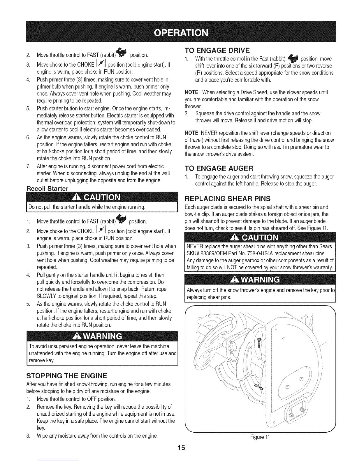
REPLACING SHEAR PINS
Eachaugerbladeis securedto thespiralshaftwitha shearpinand
bow-tieclip. Ifanaugerbladestrikesa foreignobjector icejam,the
pinwillshearoff topreventdamagetotheblade.Ifanaugerblade
doesnotturn,checkto seeifits pinhasshearedoff.SeeFigure11.
NEVERreplacethe augershearpinswithanythingotherthanSears
SKU#88389/0EMPart No.738-04124Areplacementshearpins.
Anydamagetothe augergearboxorothercomponentsas a resultof
[fa ngto dosow NOTbe coveredbyyoursnowthrowerswarranty.
Alwaysturnoff thesnowthrower'sengineandremovethekeypriorto
replacingshearpins.
Toavoid unsupervisedengineoperation,neverleavethemachine
unattendedwiththeenginerunning.Turnthe engineoffafteruseand
removekey.
STOPPING THE ENGINE
Afteryouhavefinishedsnow-throwing,runenginefora few minutes
beforestoppingtohelpdryoffany moistureontheengine.
1. MovethrottlecontroltoOFFposition.
2. Removethekey.Removingthe keywillreducethepossibilityof
unauthorizedstartingoftheenginewhileequipmentisnotin use.
Keepthekeyina safeplace.Theenginecannotstart withoutthe
key.
3. Wipeanymoistureawayfromthecontrolson theengine.
15
iJ
Figure11
s ¸......
Page 16
MAINTENANCE SCHEDULE
Beforeperforminganytypeofmaintenance/service,disengageall
controlsandstoptheengine.Waituntilallmovingpartshavecometo
acompletestop.Disconnectsparkplugwireandgrounditagainstthe
enginetopreventunintendedstarting.Alwayswearsafetyglassesduring
operationorwhileperforminganyadjustmentsorrepairs.
EachUseandevery5
hours
1st5 hours
Annuallyor25 hours
Annuallyor50 hours
Annuallyor100hours
BeforeStorage
1. Engineoil level
2. Looseor missinghardware
3. Unitand engine.
1. Engineoil
1. Sparkplug
2. Controllinkagesandpivots
3. Wheels
4. GearshaftandAugershaft
1. Engineoil
1. Sparkplug
1. Fuelsystem
1. Check
2. Tightenor replace
3. Clean
1. Change
1. Check
2. Lubewithlightoil
3. Lubewithmultipurposeautogrease
4. Lubewithlightoil
1. Change
1. Change
1. Runengineuntilit stopsfromlack
ENGINE MAINTENANCE
Checking Engine Oil
Followthemaintenanceschedulegivenbelow.Thischartdescribes
serviceguidelinesonly.UsetheServiceLogcolumntokeeptrackof
completedmaintenancetasks.Tolocate the nearest Sears Service
Centeror to scheduleservice,simplycontactSearsat
1-800-4-MY-HOME®.
offuel
f
Beforelubricating,repairing,or inspecting,disengageallcontrols
Iandstopengine.Waituntilall movingpartshavecometo a complete
_stop.
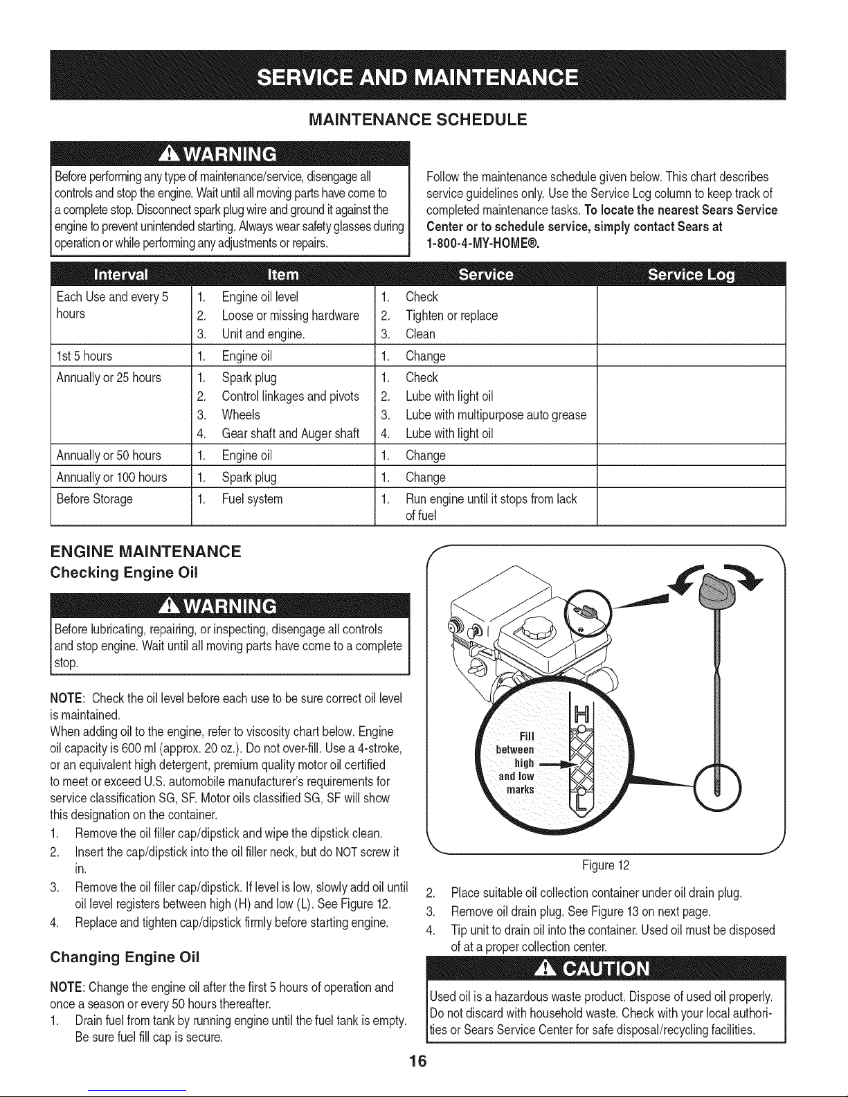
NOTE: Checktheoil levelbeforeeachuseto besurecorrectoil level
ismaintained.
Whenaddingoilto theengine,referto viscositychart below.Engine
oilcapacityis 600ml(approx.20oz.). Donotover-fill.Usea4-stroke,
oran equivalenthighdetergent,premiumqualitymotoroilcertified
tomeetorexceedU.S.automobilemanufacturer'srequirementsfor
serviceclassificationSG, SRMotoroilsclassifiedSG, SFwillshow
thisdesignationonthecontainer.
1. Removetheoil fillercap/dipstickandwipethedipstickclean.
2. Insertthe cap/dipstickintotheoilfiller neck,butdo NOTscrewit
in.
3. Removetheoil fillercap/dipstick.Iflevelis low,slowlyaddoiluntil
oil levelregistersbetweenhigh(H) andlow(L).SeeFigure12.
4. Replaceandtightencap/dipstickfirmlybeforestartingengine.
Changing Engine Oil
NOTE:Changetheengineoilafterthe first5 hoursof operationand
oncea seasonorevery50 hoursthereafter.
1. Drainfuelfromtankbyrunningengineuntilthefuel tankisempty.
Besurefuel fillcapis secure.
1 •
_i!_!iiii_ii!i!jili iiiI iiiii_H
marks
Figure12
2. Placesuitableoilcollectioncontainerunderoil drainplug.
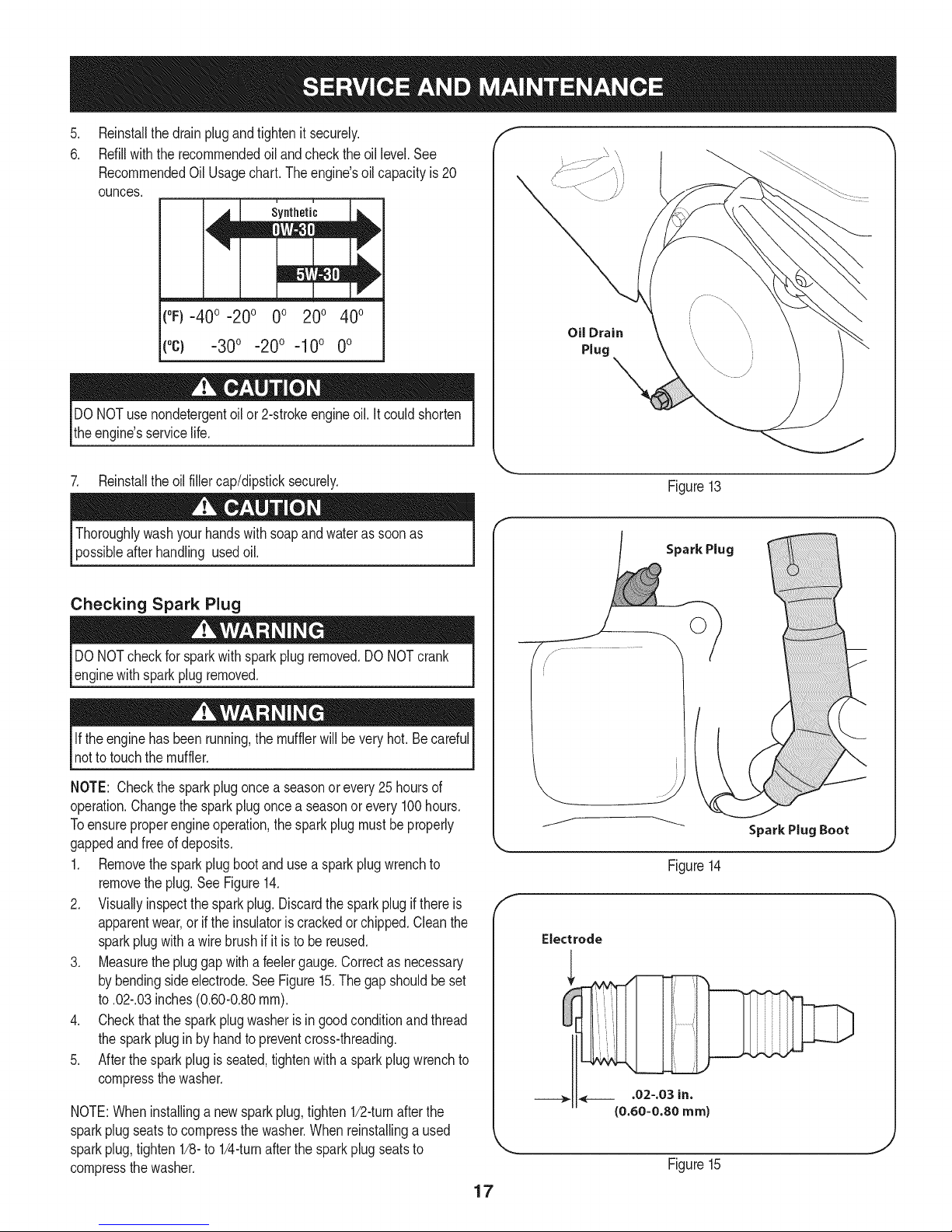
3. Removeoil drainplug.SeeFigure13on nextpage.
4. Tipunitto drainoil intothecontainer.Usedoilmustbedisposed
ofat a propercollectioncenter.
Usedoil isahazardouswasteproduct.Disposeofusedoil properly.
IDo notdiscardwithhouseholdwaste.Checkwithyourlocalauthori-
lties or SearsServiceCenterfor safedisposal/recyclingfacilities.
16
Page 17
.
Reinstallthedrainplugandtightenit securely.
6.
Refillwiththerecommendedoil andchecktheoil level.See
RecommendedOil Usagechart.Theengine'soil capacityis20
ounces.
(%-400 -200 0o 200 400
("c) -300 -200 -10° 0°
DONOTuse nondetergentoilor 2-strokeengineoil.Itcould shorten
theengine'sservicelife.
Oil Drain
Plug
7. Reinstalltheoilfillercap/dipsticksecurely.
afterhandling usedoil.
Checking Spark Plug
DONOTcheckforsparkwithsparkplugremoved.DONOTcrank
enginewithsparkplugremoved.
Iftheenginehasbeenrunning,themufflerwillbevery hot.Becareful
notto touchthemuffler.
NOTE: Checkthe sparkplugonceaseasonorevery25hoursof
operation.Changethesparkplugoncea seasonor every100hours.
Toensureproperengineoperation,the sparkplugmustbeproperly
gappedandfreeof deposits.
1. Removethesparkplugbootandusea sparkplugwrenchto
removetheplug.See Figure14.
2. Visuallyinspectthesparkplug.Discardthesparkplugif thereis
apparentwear,orif the insulatoris crackedor chipped.Cleanthe
sparkplugwitha wirebrushifitis to be reused.
3. Measurethe pluggapwitha feelergauge.Correctas necessary
bybendingsideelectrode.SeeFigure15.Thegapshouldbeset
to.02-.03inches(0.60-0.80ram).
4. Checkthatthe sparkplugwasheris ingoodconditionandthread
thesparkplugin byhandto preventcross-threading.
5. Afterthesparkplugis seated,tightenwitha sparkplugwrenchto
compressthewasher.
NOTE:Wheninstallinga newsparkplug,tighten1/2-turnafterthe
sparkplugseatsto compressthe washer.Whenreinstallinga used
sparkplug,tighten1/8-to 1/4-turnafterthesparkplugseatsto
compressthewasher.
Figure13
Spark Plug
O
J
Figure14
Electrode
.02-.03 in.
{0.60-0.80 ram)
Figure15
17
Page 18
become hotandcan inc.
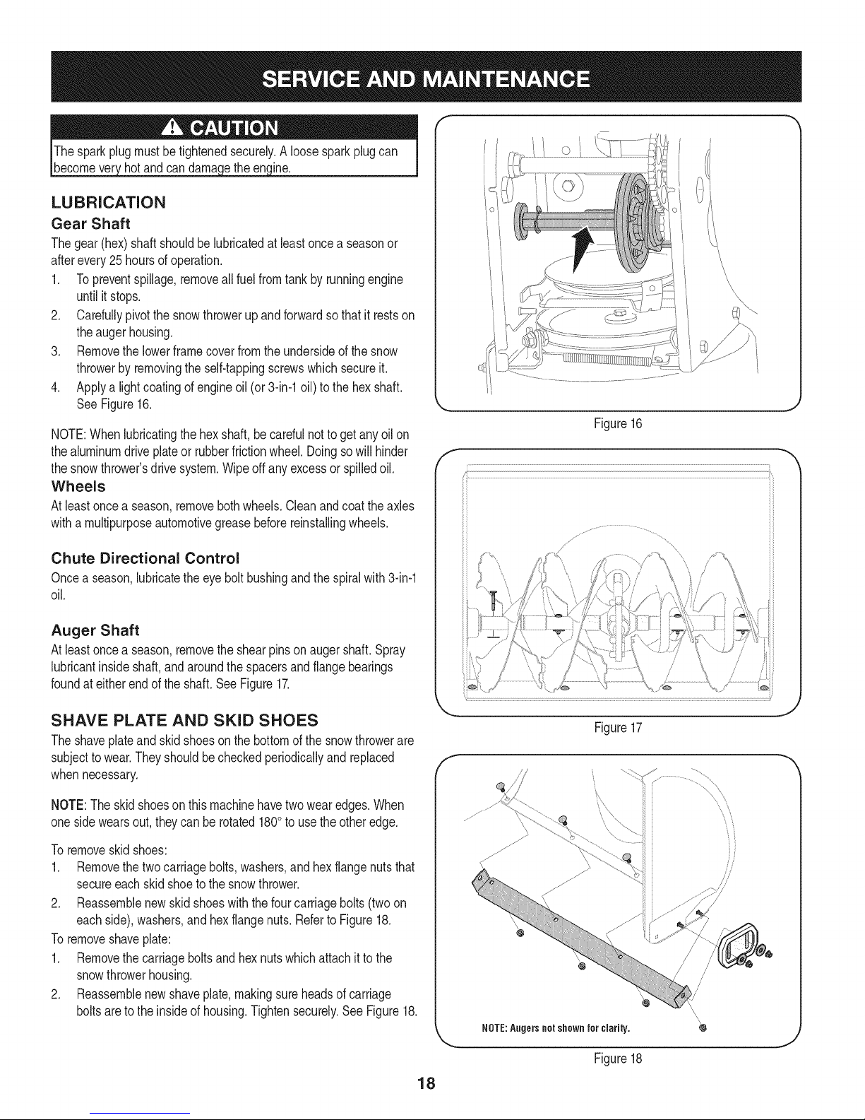
LUBRICATION
Gear Shaft
Thegear(hex)shaftshouldbe lubricatedat leastonceaseasonor
afterevery25 hoursofoperation.
1. Topreventspillage,removeallfuel fromtank byrunningengine
untilit stops.
2. Carefullypivotthesnowthrowerupandforwardsothat itrestson
theaugerhousing.
3. Removethe lowerframecoverfromthe undersideofthesnow
throwerbyremovingthe self-tappingscrewswhichsecureit.
4. Applya lightcoatingofengineoil (or3-in-1oil) tothe hexshaft.
SeeFigure16.
NOTE:Whenlubricatingthehexshaft,be carefulnotto getanyoilon
thealuminumdriveplateor rubberfrictionwheel.Doingsowill hinder
thesnowthrower'sdrive system.Wipeoffanyexcessorspilledoil.
Wheels
Atleastoncea season,removebothwheels.Cleanandcoattheaxles
witha multipurposeautomotivegreasebeforereinstallingwheels.
Chute Directional Control
Oncea season,lubricatethe eyeboltbushingand thespiralwith3-in-1
oil.
Figure16
f
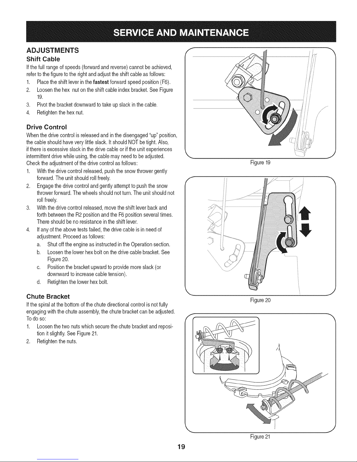
Auger Shaft
Atleastoncea season,removetheshearpinson augershaft.Spray
lubricantinsideshaft,andaroundthe spacersandflangebearings
foundat eitherendoftheshaft.SeeFigure17.
SHAVE PLATE AND SKID SHOES
Theshaveplateand skidshoesonthebottomof thesnowthrowerare
subjecttowear.Theyshouldbecheckedperiodicallyandreplaced
whennecessary.
NOTE:Theskidshoeson thismachinehavetwowearedges.When
onesidewearsout,theycan be rotated1800to usetheotheredge.
Toremoveskidshoes:
1. Removethetwocarriagebolts,washers,andhex flangenutsthat
secureeachskidshoetothe snowthrower.
2. Reassemblenewskidshoeswiththefourcarriagebolts(twoon
eachside),washers,andhex flangenuts.RefertoFigure18.
Toremoveshaveplate:
1. Removethecarriageboltsand hexnutswhichattachit tothe
snowthrowerhousing.
2. Reassemblenewshaveplate,makingsureheadsofcarriage
boltsaretothe insideof housing.Tightensecurely.SeeFigure18.
Figure17
NOTE:Augers not shown for clarity.
/
/
/
/
Figure18
18
Page 19
ADJUSTMENTS
Shift Cable
If thefull rangeof speeds(forwardandreverse)cannotbeachieved,
referto thefigureto therightandadjusttheshiftcableas follows:
1. Placetheshiftleverin thefastest forwardspeedposition(F6).
2. Loosenthehex nuton theshiftcableindexbracket.SeeFigure
19.
3. Pivotthebracketdownwardto takeupslackinthecable.
4. Retightenthehexnut.
Drive Control
Whenthedrivecontrolis releasedandinthedisengaged"up"position,
thecableshouldhaveverylittle slack.It shouldNOTbetight.Also,
ifthereisexcessiveslackin thedrive cableorifthe unitexperiences
intermittentdrivewhileusing,the cablemayneedtobeadjusted.
Checktheadjustmentofthedrivecontrolasfollows:
1. Withthedrivecontrolreleased,pushthesnowthrowergently
forward.Theunitshouldrollfreely.
2. Engagethe drivecontrolandgentlyattempttopushthesnow
throwerforward.Thewheelsshouldnotturn.Theunitshouldnot
rollfreely.
3. Withthedrivecontrolreleased,movethe shiftleverbackand
forthbetweenthe R2positionandtheF6positionseveraltimes.
Thereshouldbeno resistancein the shiftlever.
4. If anyofthe abovetestsfailed,thedrivecableisin needof
adjustment.Proceedasfollows:
a. Shutoff theengineas instructedinthe Operationsection.
b. Loosenthelowerhexboltonthe drivecablebracket.See
Figure20.
c. Positionthebracketupwardtoprovidemoreslack(or
downwardto increasecabletension).
d. Retightenthelowerhexbolt.
Figure19
f
Chute Bracket
If thespiralatthe bottomofthechutedirectionalcontrolis notfully
engagingwiththechuteassembly,the chutebracketcanbeadjusted.
Todo so:
1. Loosenthetwonutswhichsecurethechutebracketandreposi-
tionit slightly.See Figure21.
2. Retightenthenuts.
Figure20
f
Figure21
19
Page 20
Auger Control f "_
Refertothe Assemblysectionforinstructionsonadjustingtheauger
controlcable.
Skid Shoes
Refertothe Assemblysectionforinstructionsonadjustingtheskid
shoes.
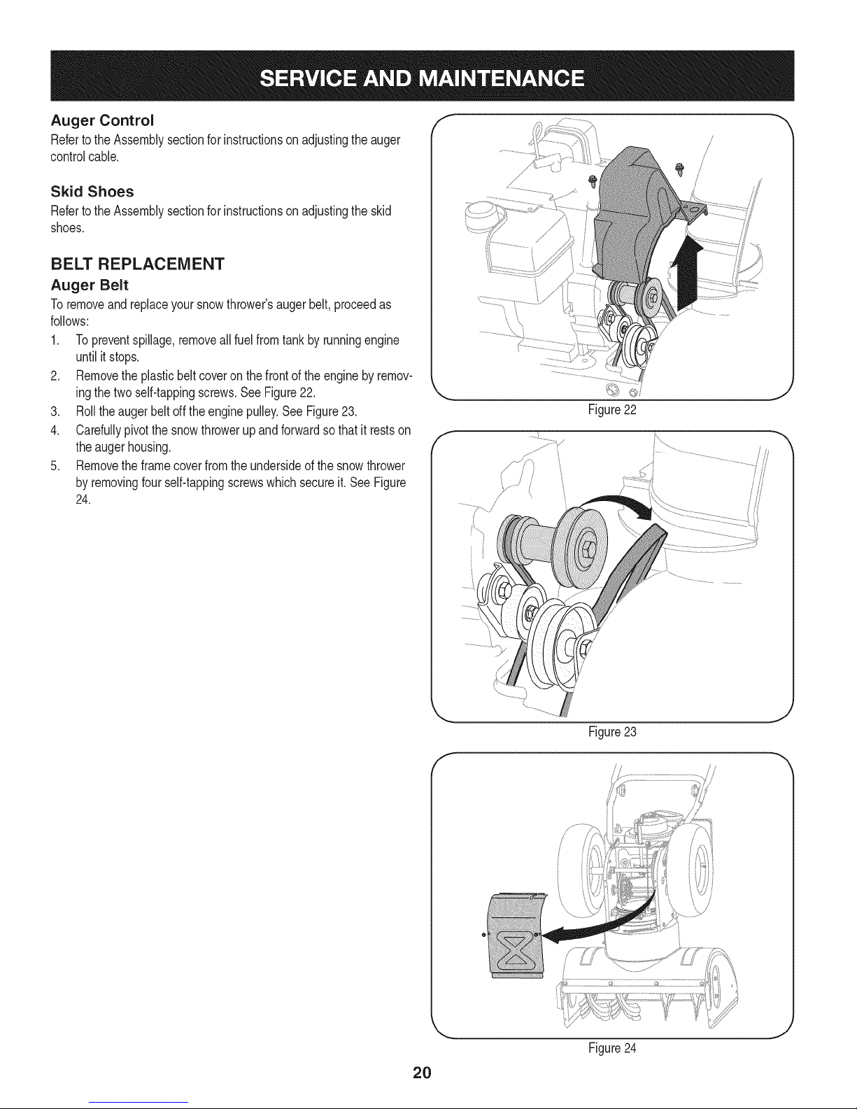
BELT REPLACEMENT
Auger Belt
Toremoveandreplaceyoursnowthrower'saugerbelt,proceedas
follows:
1. Topreventspillage,removeallfuel fromtank byrunningengine
untilitstops.
2. Removethe plasticbeltcoveronthefrontof theenginebyremov-
ingthetwoself-tappingscrews.SeeFigure22.
3. Rolltheaugerbeltoff theenginepulley.SeeFigure23.
4. Carefullypivotthesnowthrowerupandforwardsothat itrestson
theaugerhousing.
5. Removetheframecoverfromthe undersideofthe snowthrower
byremovingfourself-tappingscrewswhichsecureit.SeeFigure
24.
Figure22
f
J
Figure 23
f
//
J
Figure24
2O
Page 21
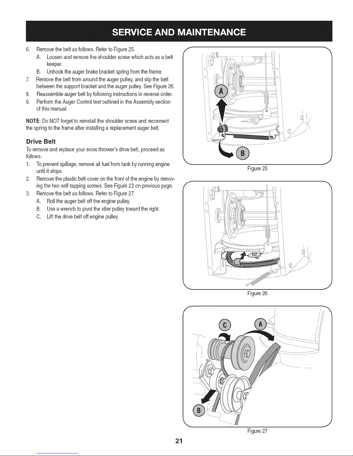
6. Removethebeltasfollows.RefertoFigure25.
A. Loosenandremovetheshoulderscrewwhichactsasabelt
keeper.
B. Unhooktheaugerbrakebracketspringfromtheframe.
7. Removethebeltfromaroundtheaugerpulley,andslipthebelt
betweenthesupportbracketandtheaugerpulley.SeeFigure26.
8. Reassembleaugerbeltbyfollowinginstructionsinreverseorder.
9. PerformtheAugerControltestoutlinedintheAssemblysection
ofthismanual.
NOTE:DoNOTforgettoreinstalltheshoulderscrewandreconnect
thespringtotheframeafterinstallingareplacementaugerbelt.
Drive Belt
Toremoveandreplaceyoursnowthrower'sdrivebelt,proceedas
follows:
1. Topreventspillage,removeallfuelfromtankby runningengine
untilit stops.
2. Removetheplasticbelt coveronthe frontoftheengineby remov-
ingthetwoself-tappingscrews.SeeFigure22on previouspage.
3. Removethebeltas follows.Referto Figure27.
A. Rolltheaugerbeltofftheenginepulley.
B. Useawrenchto pivottheidlerpulleytowardthe right.
C. Liftthe drivebeltoffenginepulley.
Figure25
Figure26
Figure27
21
Page 22
4, Carefullypivotthesnowthrowerupandforwardsothatitrestson
theaugerhousing.
5. Removetheframecoverfromtheundersideofthesnowthrower
byremovingtheself-tappingscrewswhichsecureit.Referto
Figure24,
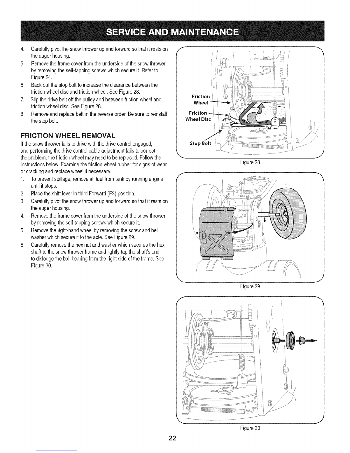
6. Backoutthestopbolttoincreasetheclearancebetweenthe
frictionwheeldiscandfrictionwheel,SeeFigure28,
7. Slipthedrivebeltoffthepulleyandbetweenfrictionwheeland
frictionwheeldisc,SeeFigure28,
8, Removeandreplacebeltinthereverseorder,Besuretoreinstall
thestopbolt.
FRiCTiON WHEEL REMOVAL
Ifthe snowthrowerfailstodrive withthedrivecontrolengaged,
andperformingthedrivecontrolcableadjustmentfailstocorrect
theproblem,thefrictionwheelmayneedtobe replaced.Followthe
instructionsbelow.Examinethefrictionwheelrubberforsignsof wear
orcrackingandreplacewheelif necessary.
1. Topreventspillage,removeallfuel fromtank byrunningengine
untilit stops.
2. Placethe shiftleverin thirdForward(F3)position.
3. Carefullypivotthesnowthrowerupandforwardsothat itrestson
theaugerhousing.
4. Removetheframecoverfromthe undersideofthe snowthrower
byremovingtheself-tappingscrewswhichsecureit.
5. Removethe right-handwheelbyremovingthescrewandbell
washerwhichsecureitto theaxle.See Figure29.
6. Carefullyremovethehexnutandwasherwhichsecuresthe hex
shaftto thesnowthrowerframeand lightlytaptheshaft'send
todislodgetheballbearingfromthe rightsideof theframe.See
Figure30.
i° i
Friction ;,
Wheel
Stop Bolt
Figure28
/ ii
22
J
Figure29
f
J
Figure30
Page 23
NOTE:Becarefulnot todamagethethreadson theshaft,
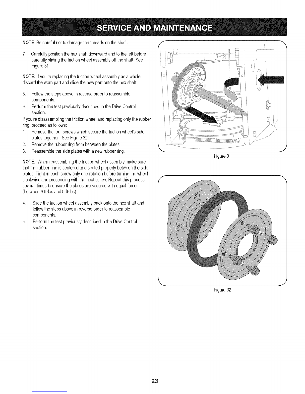
7. Carefullypositionthehexshaftdownwardandto theleft before
carefullyslidingthefrictionwheelassemblyoffthe shaft.See
Figure31.
NOTE:Ifyou'rereplacingthefrictionwheelassemblyasa whole,
discardthewornpartand slidethe newpartontothehexshaft.
8. Followthe stepsaboveinreverseorderto reassemble
components.
9. Performthetest previouslydescribedintheDriveControl
section.
If you'redisassemblingthefrictionwheeland replacingonly therubber
ring,proceedasfollows:
1. Removethefourscrewswhichsecurethe frictionwheel'sside
platestogether.SeeFigure32.
2. Removetherubberringfrombetweenthe plates.
3. Reassemblethesideplateswitha newrubberring.
NOTE: Whenreassemblingthefrictionwheelassembly,makesure
thattherubberringis centeredand seatedproperlybetweenthe side
plates.Tighteneachscrewonlyone rotationbeforeturningthe wheel
clockwiseandproceedingwiththenextscrew.Repeatthisprocess
severaltimestoensuretheplatesaresecuredwithequalforce
(between6 ft-lbsand 9 ft-lbs).
Figure31
4. Slidethefrictionwheelassemblybackontothehexshaftand
followthestepsabovein reverseordertoreassemble
components.
5. Performthetestpreviouslydescribedin theDriveControl
section.
t j
Figure32
23
Page 24

Ifthe snowthrowerwillnot be usedfor30 daysor longer,or ifit isthe endofthesnowseasonwhenthe lastpossibilityof snowis gone,the
equipmentneedstobestoredproperly.Followstorageinstructionsbelowtoensuretop performancefromthesnowthrowerformanymoreyears.
PREPARING ENGINE
Enginesstoredover30daysneedtobedrainedoffueltoprevent
deteriorationandgumfromforminginfuel systemoronessential
carburetorparts.Ifthegasolineinyourenginedeterioratesduring
storage,youmayneedto havethecarburetor,andotherfuelsystem
components,servicedor replaced.
1. Removeall fuelfromtank byrunningengineuntil itstops.Donot
attempttopourfuel fromtheengine.
2. Changetheengineoil.
3. Removesparkplugandpourapproximately1oz.(30 rnl)ofclean
engineoil intothecylinder.Pullthe recoilstarterseveraltimesto
distributetheoil,and reinstallthesparkplug.
4. Cleandebrisfromaroundengine,andunder,around,andbehind
muffler.Applya lightfilmofoilon anyareasthatare susceptible
torust.
• Storeina clean,dry andwellventilatedareaawayfromanyap-
pliancethatoperateswithaflameor pilotlight,suchas a furnace,
waterheater,or clothesdryer.Avoidany areawitha spark
producingelectricmotor,orwherepowertoolsareoperated.
Neverstoresnowthrowerwithfuelintank indoorsorinpoorlyventi-
latedareas,wherefuelfumesmayreachanopenflame,sparkor pilol
lightas ona furnace,waterheater,clothesdryerorgasappliance.
PREPARING SNOW THROWER
Whenstoringthe snowthrowerin anunventilatedormetalstor-
age shed,careshouldbetakentorustprooftheequipment.Using
a lightoilor silicone,coattheequipment,especiallyanychains,
springs,bearingsandcables.
• Removealldirt fromexteriorofengineandequipment.
• Followlubricationrecommendations.
• Storeequipmentin a clean,dryarea.
• Inflatethetirestothe maximumPSi.Referto tiresidewall.
• If possible,avoidstorageareaswithhighhumidity.
• Keepthe enginelevelinstorage.Tiltingcancausefueloroil
leakage.
24
Page 25

Enginefailstostart
Enginerunningerratically/
inconsistentRPM(huntingor
surging)
Excessivevibration
Lossofpower
Unitfailstopropelitself
Unitfailstodischargesnow
1. ChokecontrolnotinCHOKEposition.
2. Sparkplugwire disconnected.
3. Faultysparkplug.
4. Fueltankemptyor stalefuel.
5. Enginenotprimed.
6. Keynot inserted.
7. Extensioncordnotconnected(when
usingelectricstartbutton,on modelsso
equipped).
1. EnginerunningonCHOKE.
2. Stalefuel.
3. Waterordirt infuelsystem.
4. Over-governedengine.
1. Loosepartsor damagedauger.
1. Sparkplugwire loose.
2. Gascap ventholeplugged.
1. Drivecableinneedof adjustment.
2. Drivebeltlooseor damaged.
3. Wornfrictionwheel.
1. Chuteassemblyclogged.
2. Foreignobjectlodgedin auger.
3. Augercablein needof adjustment.
4. Augerbeltlooseordamaged.
5. Shearpin(s)sheared.
1. Movechokecontrolto CHOKEposition.
2. Connectwireto sparkplug.
3. Clean,adjustgap,or replace.
4. Filltankwithclean,freshgasoline.
5. Primeengineasinstructedinthe OperationSection.
6. Insertkeyfully intotheswitch.
7. Connectoneendof the extensioncordtotheelectric
starteroutletandthe otherendtoa three-prong
120-volt,grounded,ACoutlet.
1. Movechokecontrolto RUNposition.
2. Filltankwithclean,freshgasoline.
3. Drainfueltankby runningengineuntil itstops.Refill
withfreshfuel.
4. ContactyourSearsParts& RepairCenter.
1. Stopengineimmediatelyand disconnectsparkplug
wire.Tightenall boltsand nuts.Ifvibrationcontinues,
haveunit servicedbya SearsParts& RepairCenter.
1. Connectandtightensparkplugwire.
2. Removeiceand snowfromgascap. Becertainvent
holeisclear.
1. Adjustdrivecontrolcable.Referto Serviceand
Maintenancesection.
2. Replacedrive belt.Referto Serviceand Mainte-
nancesection.
3. Havefrictionwheelreplacedata SearsParts&
RepairCenter.
1. Stopengineimmediatelyand disconnectsparkplug
wire.Cleanchuteassemblyandinsideofauger
housingwithclean-outtoolor a stick.
2. Stopengineimmediatelyand disconnectsparkplug
wire.Removeobjectfromaugerwith clean-outtool
ora stick.
3. Adjustaugercontrolcable.RefertoAssembly
section.
4. Replaceaugerbelt.Referto Serviceand Mainte-
nancesection.
5. Replacewith newshearpin(s).
Chutefailstoeasilyrotate180 1. Disassemblechutecontroland reassembleas
1. Chuteassembledincorrectly.
degrees directedintheAssemblysection.
NEED HORE HELP?
Yot,Fttfind. th_ answer a!ld mo_e on ma_age_y_ifeocom _ for free]
Find this and att your other product manua[s ontine.
Get answers from our team of home experts.
Get a personalized maintenance p[an for your home.
Find information and tools to he[p with home projects.
managemylife
b_e'_g_t_/_eyeu by Sea_s
25
Page 26

Craftsman Snow Thrower Model 247.985360
/
i
26
Page 27

Craftsman Snow Thrower IViodel 247.985360
D = 0 0
731-2635 SnowRemovalToolMount
2. 684-04057A-0637 ImpellerAssembly,12"Dia.
3. 710-0347 HexScrew,3/8-16,1.75,Gr5
4. 710-0451 Bolt,Carriage,5/16-18,.750Grl
5. 710-04484 Screw, 5/16-18,0.750
6. 710-0703 Screw,Carriage,1/4-20,.750,Gr5
7. 712-04063 Nut,FlangeLock,5/16-18,Nylon
8. 712-04064 Nut,FlangeLock,1/4-20,Nylon
9. 712-04065 Nut,FlangeLock,3/8-16,Nylon
10. 714-04040 CotterPin,Bow-tie
11. 725-0157 Cable,Tie,3/16x .05x7.4
12. 926-04012 Nut,Push-on,.25Dia
13. 731-04705D Chute,Adapter5" Dia
14. 732-04460 Spring,Extension,.38ODx 4.59
15. 736-0174 Washer,Wave,.625x .885x.015
16. 736-0242 Washer,Bell,.340x .872x .060
17. 946-04230A ClutchCable,Auger,47.23"
18. 931-2643 SnowRemovalTool
19. 738-0143 Screw,Shoulder,.498x .34,3/8-16
20. 938-0281 Screw,Shoulder,.625x .17,3/8-16
21. 738-04124A ShearPin,.25x 1.50
22. 941-0245 Bearing,HexFlangex.75 ID
23. 941-0309 Bearing,Ball,.75IDx 1.85OD
24. 756-04224 FlatPulley,Idler, 2.75OD
25. 790-00075 Housing,Bearing,1.85ID
26. 790-00080B Bracket,AugerIdlerw/Brake
27. 918-04171B GearboxAssembly,Auger,24"
28. 684-04265-4044 HousingAssembly,Auger24"
D = O
684-04107-0637
30. 684-04108-0637
31. 731-04870
32. 736-0188
33. 741-0493A
34. 790-00087A-0637
35. 790-00120-4044
36. 731-06439
37. 918-0123A
38. 918-0124A
39. 921-0338
40. 741-0662
41. 710-0642
42. 711-04285
43. 914-0161
SpiralAssembly,LH
SpiralAssembly,RH
Spacer,1.25ODx.75 IDx 1.00
Washer,Flat,.76x 1.49x.06
Bushing,Flange,.80IDx .91OD
Housing,1"HexBearing
ShavePlate,2.25x 23.66
SlideShoe
Housing,Gearbox,RH
Housing,Gearbox,LH
Seal,Oil, .750x 1.00x .125
Bearing,Flange,.75x 1.0x .59
Screw,Self-tapping,1/4-20,0.750
Axle,Auger,24"
Key,Hi-pro3/16x5/8
44. 715-04021 Pin,Dowel,.25ODx 1.2
45. 917-04126 Shaft,Worm.75OD
46. 917-04861 Gear,Worm20T
47. 718-04071 Collar,Thrust
48. 721-0325 Plug,1/4x .437
49. 721-0327 Seal,Oil, .75x 1x .131
50. 936-0351 Washer,Flat,.760IDx 1.50D
51. 736-3084 Washer,Flat,.51x 1.12
52. 741-0663 Bearing,Flange,.75x 1.0x .925
53. 741-0661A Bearing,Flange,.75x 1.00x .975
54. 936-0159 Washer,Fiat,.349x .879x .063
55. 710-0276 Screw,Carriage,5/16-18x 1.00
27
Page 28

Craftsman Snow Thrower Model 247.985360
f
. --J
,; //
/ !
/; /i
\
//
,/
28
Page 29

Craftsman Snow Thrower IViodel 247.985360
D = " 0
631-04133A HandleAssembly,ClutchLock,LH
2. 631-04134B HandleAssembly,ClutchLock,RH
3. 684-04111B HandleAss'y,Engage,LH
4. 684-041120 HandleAss'y,Engage,RH
5: J631-04131B LChute,Lower(Inc!.Ref.# 27,Qty.3)
6. 790-00248C-0637 Bracket,Panel
7. 914-0145 ClickPin
8. 710-04586 Screw,1/4-20x 1.625
9. 790-00219-4044 Panel,Handle,(nocutout)
10. 710-1233 Screw,Machine,#10-24,1.375
11. 914-0104 Pin,Cotter,.072x 1.13
12. 712-04063 Nut,FlangeLock,5/16-18,Nylon
13. 749-04190A-0637 Handle,Upper,RH
14. 936-0185 Washer,Fiat,.375x .738x .063
15. 720-0274 Grip,1.0IDx5.0
16. 720-04039 Knob,Shift,Black
17. 735-0234 Grommet,.44IDx .94 ODx .50
18. 926-0100 Cap,Push,3/8 Rod
19. 732-0193 Spring,.39 x .60x .88
20. 920-0284 Knob,5/16-18,Black
21. 720-0201A CrankKnob,1.0Dia.x 3.2, Black
22. 749-04138A-0637 Handle,Lower
23. 935-0199A Bumper,Rubber,.62 ODx .22
24. 736-0262 Washer,Fiat,.385x .870x .092
=
25. 738-04118 Bolt,Shoulder,5/16-18x0.905
26. 738-04348 Screw,Shoulder,.43x 1.3,1/4-20
D = W
731-04869A Chute,FlangeKeeper
28. 946-04397A Cable,SpeedSelector
29. 749-04191A-0637 Handle,Upper,LH
30. 747-04263 EyeBolt,ChuteCrank
31. 790-00313-0637 Sh!flLever
32. 731-04912B Chute,Lower,5.0Dia.
33. 710-0276 Bolt,Carriage,5/16-18,1.0
34. 710-04071 Bolt,Carriage,5/16-18,1.0
35. 710-0451 Bolt,Carriage,5/16-18,.750
36. 731-04426A Chute,Upper,w/Label
37. 936-0159 Washer,.349x .879x .063
38. 941-0475 Bushing,Plastic,.380
39. 784-5647-0637 Bracket,ChuteCrank
40. 684-04104-0637 CrankAssembly,Chute
41. 710-0572 Screw,Carriage,5/16-18,2.25
42. 710-04484 Screw,5/16-18,2.25,Gr5
43. 684-04250 Rod,Pivot
44. 710-04326 Screw,#8-16x.50
45. 710-3069 Screw,1/4-20x.50
46. 712-04081A Nut,Hex,1/4-20
47. 731-04894D Plate,Lock
48. 731-04896B Cam,ClutchLock
49. 731-06471 HandlePanelCover
50. 732-04219C Spring,ClutchLock
51. 732-04238 Spring,Torsion,.8156IDx .3038
29
Page 30

Craftsman Snow Thrower IViodel 247.985360
A
A
3O
/
/
/
/
Page 31

Craftsman Snow Thrower IViodel 247.985360
I = 0 0
656-04055 DiscAssembly,FrictionWheel
2. 684-04153 FrictionWheelAssembly,5.50D
3. 684-04154B-0637 SupportBracket,FrictionWheel
4. 684-04156A ShiftAssembly,Rod
5. J710-0627 J HexScrew,5/16-24,.750,Gr5
6. 710-0788 Screw,1/4-20,1.000
7. 710-1652 Screw,1/4-20x .625
8. 712-04065 Nut,FlangeLock,3/8-16,Nylon
9. 712-0417A Nut,Flange,5/8-18
10. 914-0126 Key,HiPro,3/16x 3/4 Dia.
11. 916-0104 E-ring,.500Dia.
12. 716-0136 E-ring,Retaining,.875Dia.
13. 916-0231 E-ring,.750Dia.
14. 917-04209A HexShaft,.8125,7-Tooth
15. 917-04230A Gear,80-Tooth
16. .726-0221 Speed Nut,.500
17. 932-0264 ExtensionSpring
18. 736-0242 Washer,Bell,.340x .872x .060
19. 936-0287 Washer,Flat,.793x 1.24x .060
20. 736-04161 Washer,Flat,.75x 1.00x .060
21. 790-00289A-0637 Plate,Cover
22. 738-04439 ShoulderScrew
23. 738-04184A Screw,Shoulder,.37x .105,1/4-20
24. 738-0924A Screw,1/4-28,.375
25. 941-0245 Bearing,HexFlangex .75ID
26. 941-0563 Bearing,Ball,17x 40x 12
27. 946-04229B ClutchCable,Wheel,44.95"
28. 935-04054 Rubber,FrictionWheel,5.50D
29. 748-0190 Spacer,.508IDx .75ODx .68
30. 756-0625 Roller,Cable
31. 790-00096-0637 FrontGuideBracket,AugerCable
32. 790-00180A-4044 Frame
33. 790-00206A-0637 GuideBracket,AugerCable
34. 790-00207C GuideBracket,DriveCable
35. 790-00316-0637 Cover,Frame
36. 634-04167A-0911 LHWheelAssembly
634-04168A-0911 RHWheelAssembly
D = O e
731-04873 Spacer,1.25x .75x 3.0
38. 938-04168 Axle,.75x22"
39. 936-0329 Washer,Lock, 1/4
40. 710-0809 HexScrew,1/4-20,1.25,Gr5
41. 710-0191 HexScrew,3/8-24,1.25,Gr8
42. 710-0672 HexScrew,5/16-24,1.25,Gr5
43. 710-0654A Screw,Seres,3/8-16,1.00
44. 710-1245B HexScrew,5/16-24,.875,Gr8
45. 710-0896 Screw,1/4-20x .625
46. 926-04012 Nut,Push-on,.25 Dia.
47. 731-04792A Cover,Belt
48. 732-04308A Spring,Torsion,.850 IDx .354
49. 736-0247 Washer,Flat, .406x 1.25x.157
50. 936-0119 Washer,Lock.3125
51. 736-0505 Washer,Flat, .34x 1.50x.150
52. 748-04053A Pulley,Adapter,.75 Dia.
53. 748-04112B Spacer,Shoulder,.317x.50x .102
54. 750-04303 Spacer,.875IDx 1.185OD
55. 750-04477A Spacer,.340x.750x.360
56. 954-04050 Belt,AugerDrive
57. 954-04260 Belt,WheelDrive
58. 756-04109 Pulley,AugerDrive,8.1x .5
59. 756-04113 Pulley,Half,V x2.600OD
60. 756-04252 Pulley,Half,3/8-Vx 1.7160OD
61. 790-00208C IdlerBracket,Wheel Drive
62. 684-04169 Idler PulleyAssembly
63. 750-04571 Spacer,Shoulder,.26x .79x .538
64. 735-04099 Plug,3/8 ID
65. 735-04100 Plug,1/2ID
66. 712-04064 Nut,FlangeLock,1/4-20,Nylon
67. 710-0751 HexScrew,1/4-20,.620,Gr5
68. 732-04311A Spring,Torsion,.750IDx .968
69. 712-04063 Nut, FlangeLock,5/16-18,Nylon
70. 936-3015 Wash.,Flat,.469x .875x .105
71. 790-00217A-0637 PivotBracket,SpeedSelector
72. 790-00218A-0637 ShiftBracket,SpeedSelector
73. 952Z270-SUA ReplacementEngine
31
Page 32

Craftsman Engine Model 270=SUA For Snow Model 247.985360
24
23
23
m
l
i
i19
!
i
120
i
i
i
i20
!
!
i
121
i
i
122
i
i
i
i23
!
i
i
124
i
951-11282
710-05001
951-14190
951-11289
712-04214
710-04915
951-10642B
2
21
m = 0 O
MufflerAssembly
MufflerStud
MufflerStudKit
MufflerGasket
Nut- M8
Bolt- M6X 12Zin
MufflerShroud
32
Page 33

Craftsman Engine Model 270=SUA For Snow Model 247.985360
41 _42
m
34
35
36
37
39
4O
41
42
43
951-10634
712-04213
951-11284
951-10757
951-10637
731-05632
951-10640
951-10635
710-04943
°0
Shroud-Engine
Nut
ChokeKnob
ThrottleKnob
Switch-Ignition
IgnitionKeySwitch
PushRod-Choke
Air FilterHeating
Bolt-M61X28MSpec
37
35
D = O O
33
Page 34

Craftsman Engine IViodel 270=SUA For Snow IViodel 247.985360
131-6asketKit-Complete
132-6asketKit-External
133- CompleteEngine
34
Page 35

Craftsman Engine IViodel 270=SUA For Snow IViodel 247.985360
m
5O
51
52
53
54
55
56
57
58
59
6O
61
62
63
64
65
66
67
68
69
951-12111
951-11632
951-12007
951-11633
710-04915
951-11113
951-11573
951-14053
736-04461
951-11902
714-04078
951-11575
951-11369
951-10307
951-11247A
951-11576
715-04092
715-04096
951-11371
951-12125
951-11246
D = O
PistonRingSet
PistonPinSnapRing
Piston
PistonPin
Bolt- M6X 12Zin
Shield- Air
ConnectingRodAssembly
GovernorShaft
Washer
GovernorSeal
CotterPin
CamshaftAssembly
Bearing
Key:Flywheel
CrankshaftKit
(Incl.62,63,64,74,79)
GovernorGear/Shaft
Pin-Dowel
DowlPin9X14
CrankcaseCoverGasket
CrankcaseCover
CrankcaseCoverKit
(Incl.62,68-74)
m
7O
71
73
74
75
76
77
78
79
130
131
132
133
710-04932
951-11283
951-11577
951-11368
951-11249
951-11060B
951-11350
736-04440
710-04906
951-11370
951-10641
951-11059A
951-10661B
952Z270-SUA
D = O O
Bolt
Oil FillPlugAssembly
O-Ring15.8X 2.5
OilSeal
CrankcaseKit
(Incl.59,62,74,75,79)
ShortblockAssembly
(Incl.4,21,27-29,44,46,
47,50-53,56-79)
Oil DrainPipe
Washer
Bolt- DrainPlug
OilSeal
Oil DrainAssembly
GasketKit-Complete
(Incl.4,21,27-29,32,44,
58,59,68,74,77,79)
GasketKit-External
(Incl.4,21,27-29,32,77)
CompleteEngine
35
Page 36

Craftsman Engine Model 270-SUA For Snow Model 247.985360
18
15
13
44 _p 49 46 _46
129
_ U" -"45
17
131-GasketKit-Complete
132-GasketKit-External
133-CompleteEngine
36
Page 37

Craftsman Engine IViodel 270=SUA For Snow IViodel 247.985360
m
1
2
3a
3b
4
5
6
7
8
9
10
11
12
13
14
15
16
17
18
44
45
46
47
48
49
129
131
132
133
710-04968
951-11054A
731-07059
726-04101
951-11565
951-12000
951-11892
751-11124
751-11123
951-11893
710-04902
951-12002
951-12003
951-12004
951-11894
710-04933
951-11895
951-10722B
951-10292
951-11572
951-10648
951-11899
715-04108
951-10647A
951-10647A
951-12626
951-11059A
951-10661B
952Z270-SUA
D = O O
FlangeBoltM6
ValveCover
Hose-Breather
Clamp-BreatherHose
ValveCoverGasket
IntakeValveSpringRetainer
RockerArmAssembly
Nut- PivotLockin
Nut- ValveAdjust
RockerArm
Bolt- Pivot
ExhaustValveAdjuster
ExhaustValveSpringRetainer
ValveSpring
IntakeValveSeal
Bolt- M8X 55Zin
PushRodGuide
CylinderHeadAssembly
(Incl.4-14,16,17,21,27-29,
44,48,49)
Plug:Spark
Gasket-CylinderHead
Kit-PushRod
Tappet
Pin-Dow110X 16
ValveKit
ValveKit
ValveCoverKit
GasketKit-Complete
(Incl.4,21,27-29,32,44,
58,59,68,74,77,79)
GasketKit-External
(Incl.4,21,27-29,32,77)
CompleteEngine
37
Page 38

Craftsman Engine IViodel 270=SUA For Snow IViodel 247.985360
134-CarburetorKit- Deni
135- CarburetorKit-Huayi
27
w
38
Page 39

Craftsman Engine IViodel 270=SUA For Snow IViodel 247.985360
m
25
26
27
28
29
30
30
31
31
32
33
134
135
a
b
C
d
e
f
g
h
I
J
k
I
I1q
n
o
P
q
r
s
t
U
V
W
X
Y
710-04939
710-04910
951-11567
951-11896
951-11569A
951-10639A
951-11824
951-14026A
951-14027A
951-11897
951-11112
951-14154
951-12788A
n/a
n/a
n/a
n/a
710-05469
736-04638
n/a
n/a
n/a
n/a
951-11699
951-11906
n/a
n/a
n/a
951-12875
n/a
n/a
n/a
951-11589
n/a
951-11348
710-04945
951-11349
710-04938
D = W O
Stud-Carb
Stud- M6X 105
Gasket-CarbInsulator
CarburetorInsuiat
CarburetorGasket
Primer
PrimerBulb
CarburetorAssembly- Huayi
CarburetorAssembly- Deni
CarburetorGasket
Bracket-ChokeControl
CarburetorKit- Deni
(Incl.h,n,o,p,q,r,s,t,u,x)
CarburetorKit- Huayi
(Incl.h,n,o,p,q,r,s,t,u,x)
ChokeShaft
ChokePlate
ThrottleShaft
ThrottlePlate
ScrewM3x5
LockWasher
Gasket,ThrottlePlate
IdleJet Assembly
IdleSpeedAdjustingScrew
MixtureScrew
PrimerHose
HoseClamp
CarburetorBody
FloatPin
EmulsionTube
FloatNeedleValve
MainJet
NeedleValveSpring
Float
FuelBowlGasket
FuelBowl
FuelBowlGasket
FuelBowlMountingBolt
FuelDrainPlugGasket
FuelDrainPlug
39
Page 40

Craftsman Engine IViodel 270-SUA For Snow IViodel 247.985360
82
84
85
m
8O
81
82
83
84
85
86
87
88
90
91
92
93
951-10646
951-11110
710-04940
710-04919
951-12416
951-10934
951-10911
712-04209
710-04915
951-10663A
736-04455
710-04974
951-14151
D = O O
IgnitionCoil
Shield- Air Flow
Bolt
Bolt- FlangeM6
Flywheel
CoolingFan
StarterCup
Nut- M14
Bolt- M6X 12Zin
FanCoverComplete
FlatWasher-Recoil
FlangeBoltM6
RecoilStartAssembly
4O
Page 41

Craftsman Engine IViodel 270=SUA For Snow IViodel 247.985360
95 102 _---115
,114
115
m
94
95
96
97
98
99
101
102
103
104
105
106
9s- 97 9s
94
951-10758
710-05103
951-11108
951-11935
951-10664
951-10665
951-11106
712-04212
710-04908
951-11700
951-10650
710-04915
ThrottleControlAssembly
Bolt-M6X 12
Shield- Governor
GovernorSpring
Spring-ThrottleReturn
Rod-Governor
Bracket-Governor
Nut- M6
Bolt- M6X 21 Gov
HoseClamp-Oarb
Kit-FuelLine
Bolt- M6X 12Zin
D = O 0
105
104
105
m
107
108
109
110
111
112
113
114
115
116
117
951-11914
710-04905
710-04915
951-11913
951-11381
951-10656
951-11904
951-12482
951-12533
951-11933
951-10653B
D = O 0
Engine/DipstickCover
Bolt
Bolt- M6X 12Zin
Oil FillTubeAssembly
O-Ring
DipstickTube
O-RingDipstick
DipstickAssy
FuelCap
FuelLevelIndicator
FuelTank
41
Page 42

Craftsman Engine IViodel 270=SUA For Snow IViodel 247.985360
23
m
i
1118
1
1
1
i119
!
i
i 120
1
1
1
1121
1
1
1
i 122
!
i
i 123
1
1
1
i 124
!
!
i
i 125
1
1
i 126
1
1
1
i 127
!
i
1
i 128
1
710-04914
951-11680
951-11114
712-05015
710-04965
710-04935
710-05182
715-04088
951-10645A
710-04915
951-11109
D = O !
Bolt- FlangeM6
FlexibleClamp
Bracket-SwitchHousingMount
Nut
ScrewM4X 55
Screw- M4X 60
Bolt-M6X 32
Pin- Dowel
ElectricStarter
Bolt- M6X 12Zin
Shield- BlowerHousing
42
Page 43

Craftsman Snow Thrower Model 247.985360
777S32636
1001 J,nO-NV:llO
7VnNVW S,HOIVH3dOQV3H"G
"S3OVJHflS]3AVH9H09NIlV_3d0
N3HMN011nv3VUIX]3sn"$830N¥1S181¥398VH3SI0
1O3Ul0U3A3N'S]lSnPNI 8133r80 NMOUHLQIOM 01 "_
"3NIHOVW9NIOIAS]S80 9NI99033Nn
3UOJ38o3aa01S3MH SIUVd9NIAO_J]]V ]llNn S3]ONVH
QNIH38NIV_3UQNV'3NIGH3dOIS'SH]A3]HOlfl]O30VON3SIQ"8
"31flH330UVHOSIO9010NilOl 1001LflO-NV3]33Sfl"_
"133JONVSONVH31VlfldWVNV3U39flV_0U]]]_d_l HIlM
lOVlNO3"U39flVONV83113dWI9NllVlOUWOSJIVMVd33H"L
777S32236
777D16340
777X43688
NOT
/IUSI_E85 ORFUEL
CONTAININGMORE
THAN10% ETHANOL
)
777D16341
777122363
777123030
777D18044
777D16355
777123031
43
Page 44

MTD CONSUMER GROUP INC (MTD), the California Air Resources Board (CARB)
and the United States Environment Protection Agency (U. S. EPA)
Emission Control System Warranty Statement
(Owner's Defect Warranty Rights and Obligations)
EMISSIONCONTROLSYSTEMCOVERAGEISAPPLICABLETOCERTIFIEDENGINESPURCHASEDINCALIFORNIAIN2005ANDTHERE-
AFTER,WHICHAREUSEDINCALIFORNIA,ANDTOCERTIFIEDMODELYEAR2005ANDLATERENGINESWHICHAREPURCHASEDAND
USEDELSEWHEREINTHEUNITEDSTATES.
Californiaandelsewherein theUnitedStatesEmissionControlDefectsWarrantyCoverage
TheCaliforniaAir ResourcesBoard(CARB),U.S.EPAandMTDarepleasedto explaintheemissionscontrolsystemwarrantyonyourmodelyear
2006andlatersmalloff-roadengine.InCalifornia,newsmalloff-roadenginesmustbe designed,builtand equippedtomeettheStatesanti-smog
standards.Elsewhereinthe UnitedStates,newnon-road,spark-ignitionenginescertifiedfor model2005andlater,mustmeetsimilarstandardsset
forthbythe U.S.EPA.MTDmustwarrantytheemissioncontrolsystemonyourengineforthe periodoftimelistedbelow,providedtherehasbeen
noabuse,neglector impropermaintenanceofyoursmalloff-roadengine.
Youremissioncontrolsystemmayincludepartssuchasthecarburetor,fuel-injectionsystem,theignitionsystem,andcatalyticconverter,fueltanks,
fuellines,fuel caps,valves,canisters,filters,vaporhoses,clamps,connectors,andotherassociatedemission-relatedcomponents.
Whereawarrantableconditionexists,MTDwill repairyoursmalloff-roadengineat nocostto yourincludingdiagnosis,partsand labor.
MANUFACTURER'S WARRANTY COVERAGE:
Thisemissionscontrolsystemiswarrantedfor twoyears.Ifanyemission-relatedpartonyourengineis defective,thepartwill berepairedor
replacedbyMTD.
OWNER'S WARRANTY RESPONSIBILITIES:
Asthe smalloff-roadengineowner,youareresponsibleforthe performanceofthe requiredmaintenancelistedinyourOwner'sManual.MTD
recommendsthatyouretainall yourreceiptscoveringmaintenanceson yoursmalloff-roadengine,butMTDcannot denywarrantysolelyfor the
lackofreceiptsor foryourfailureto ensuretheperformancetoallscheduledmaintenance.
Asthe smalloff-roadengineowner,youshouldhoweverbeawarethat MTDmaydenyyourwarrantycoverageif yoursmalloff-roadengineorpart
hasfaileddue toabuse,neglect,impropermaintenanceor unapprovedmodifications.
Youare responsibleforpresentingyoursmalloff-roadengineto an AuthorizedMTDServiceDealeras soonasa problemexists.Thewarranted
repairsshouldbe completedina reasonableamountoftime,nottoexceed30 days.
Ifyouhaveanyquestionsregardingyourwarrantyrightsand responsibilities,you shouldcontacta MTDServiceRepresentativeat 1-800-800-7310
andaddressisMTDCONSUMERGROUP,RO.Box361131,ClevelandOH,44136-0019.
DEFECTS WARRANTY REQUIREMENTS FOR 1995 AND LATER SMALL OFF-ROAD ENGINES:
Thissectionappliesto 1995andlatersmalloff-roadengines.Thewarrantyperiodbeginsonthedatetheengineor equipmentisdeliveredtoan
ultimatepurchaser.
(a) GeneralEmissionsWarrantyCoverage_
MTDmustwarranttothe ultimatepurchaserandeachsubsequentpurchaserthatthe engineis:
(1)Designed,built,andequippedsoasto conformwithallapplicableregulationsadoptedbytheAirResourcesBoardpursuantto itsauthorityin
Chapters1and2,Part5, Division26of the HealthandSafetyCode;and
(2) Freefromdefectsinmaterialsandworkmanshipthatcausethe failureofa warrantedparttobeidenticalin all materialrespectsto the partas
describedin theenginemanufacturer'sapplicationforcertificationfora periodof twoyears.
.(b)The warrantyonemissions-relatedpartswillbe interpretedas follows:
(1)Anywarrantedpartthatisnot scheduledfor replacementas requiredmaintenanceinthewritteninstructionsrequiredby Subsection(c)
mustbewarrantedforthewarrantyperioddefinedinSubsection(a)(2).Ifanysuchpartfailsduringtheperiodof warrantycoverage,it mustbe
repairedor replacedbyMTDaccordingto Subsection(4)below.Anysuchpartrepairedor replacedunderthewarrantymustbewarrantedfor
theremainingwarrantyperiod.
(2)Anywarrantedpartthat isscheduledonlyfor regularinspectioninthewritteninstructionsrequiredbySubsection(c) mustbewarrantedfor
thewarrantyperioddefinedinSubsection(a)(2).A statementinsuchwritteninstructionsto theeffectof"repairor replaceasnecessary"will
notreducetheperiodof warrantycoverage.Anysuchpartrepairedorreplacedunderwarrantymustbe warrantedfortheremainingwarranty
period.
(3) Anywarrantedpartthat whichisscheduledfor replacementas requiredmaintenanceinthewritteninstructionsrequiredbySubsection(c)
mustbewarrantedfortheperiodof timepriortothefirst scheduledreplacementpointforthatpart.Ifthepart failspriorto thefirstscheduled
replacement,thepart mustberepairedor replacedby MTDaccordingtoSubsection(4) below.Any suchpart repairedorreplacedunder
warrantymustbewarrantedfortheremainderoftheperiodpriortothe firstscheduledreplacementpointfor the part.
(4) Repairorreplacementof any warrantedpartunderthewarrantyprovisionsof thisarticlemustbeperformedatnochargetotheownerata
warrantystation.
(5) Notwithstandingtheprovisionsof Subsection(4)above,warrantyservicesorrepairsmustbe providedatall MTDdistributioncentersthat
arefranchisedto servicethesubjectengines.
Page 45

(6)Theownermustnotbechargedfordiagnosticlaborthatleadstothedeterminationthatawarrantedpartisinfactdefective,providedthat
suchdiagnosticworkisperformedatawarrantystation.
(7)Theenginemanufacturerisliablefordamagestootherenginecomponentsproximatelycausedbyafailureunderwarrantyofanywarranted
part.
(8)Throughouttheengine'swarrantyperioddefinedinSubsection(a)(2),MTDwillmaintainasupplyofwarrantedpartssufficienttomeetthe
expecteddemandforsuchparts.
(9)Anyreplacementpartmaybeusedintheperformanceofanywarrantymaintenanceorrepairsandmustbeprovidedwithoutchargetothe
owner.SuchusewillnotreducethewarrantyobligationsofMTD.
(10)Add-onormodifiedpartsthatarenotexemptedbytheAirResourcesBoardmaynotbeused.Theuseofanynon-exemptedadd-onor
modifiedpartsshallbegroundsfordisallowingawarrantyclaimmadeinaccordancewiththisarticle.Theenginemanufacturershallnotbe
liableunderthisarticletowarrantfailuresofwarrantedpartscausedbytheuseofnon-exemptedadd-onormodifiedpart.
(c)MTDwillincludea copyofthefollowingemissionwarrantypartslistwitheachnewengine,usingthoseportionsofthelistapplicabletothe
e__&gine.
(1)FuelMeteringSystem
•Coldstart enrichmentsystem(softchoke)
,,Carburetorandinternalparts
•FuelPump
•FuelTank
(2)Air InductionSystem
•Aircleaner
•Intakemanifold
(3) IgnitionSystem
•Sparkplug(s)
•MagnetoIgnitionSystem
(4)ExhaustSystem
Catalyticconverter
•SAI(Reedvalve)
(5) MiscellaneousItemsUsedin AboveSystem
Vacuum,temperature,position,timesensitivevalvesandswitches
Connectorsandassemblies
(6) Evaporativecontrol
•FuelHosecertifiedforARBevaporativeemissionof2006.
•FuelHoseClamps
Tetheredfuelcap
Carboncanister
•Vaporlines
GD0C-100174Rev.B
Page 46

Look For Relevant Emissions Durability Period and
Air index information On Your Engine Emissions Label
Engines that are certified to meet the California Air Resources Board (CARB) Tier 2 Emission Standards must
display information regarding the Emissions Durability Period and the Air Index. Sears Brands Management
Corporation makes this information available to the consumer on our emission labels.
The Emissions Durability Period describes the number of hours of actual running time for which the engine is
certified to be emissions compliant, assuming proper maintenance in accordance with the Operating & Mainte-
nance Instructions. The following categories are used:
Moderate: Engine is certified to be emission compliant for 125 hours of actual engine running time.
Intermediate: Engine is certified to be emission compliant for 250 hours of actual engine running time.
Extended: Engine is certified to be emission compliant for 500 hours of actual engine running time.
For example, a typical walk-behind lawn mower is used 20 to 25 hours per year. Therefore, the Emissions
Durability Period of an engine with an intermediate rating would equate to 10 to 12 years.
The Air index is a calculated number describing the relative level of emissions for a specific engine family. The
lower the Air Index, the cleaner the engine. This information is displayed in graphical form on the emissions label.
After July 1,2000, Look For Emissions Compliance Period
On Engine Emissions Compliance Label
After July 1, 2000 certain Sears Brands Management Corporation engines will be certified to meet the United
States Environmental Protection Agency (USEPA) Phase 2 emission standards. For Phase 2 certified engines, the
Emissions Compliance Period referred to on the Emissions Compliance label indicates the number of operating
hours for which the engine has been shown to meet Federal emission requirements.
For engines less than 225 cc displacement, Category C = 125 hours, B = 250 hours and A = 500 hours.
For engines of 225 cc or more, Category C = 250 hours, B = 500 hours and A = 1000 hours.
This is a generic representation of the emission label typically found on a certified engine.
FAMILYYBSXS.3192VA 274812
GDOC-100182Rev.B
46
Page 47

Congratulations on making a smart purchase. Your new Craftsman® product is designed and
manufactured for years of dependable operation. But like all products, it may require repair
from time to time. That's when having a Repair Protection Agreement can save you money and
aggravation.
Here's what the Repair Protection Agreement* includes:
[] Expert service by our 10,000 professional repair specialists
[] Unlimited service and no charge for parts and labor on all covered repairs
[] Product replacement up to $1500 if your covered product can't be fixed
[] Discount of 25% from regular price of service and related installed parts not covered by the
agreement; also, 25% off regular price of preventive maintenance check
[] Fast help by phone - we call it Rapid Resolution - phone support from a Sears representative.
Think of us as a "talking owner's manual."
Once you purchase the Repair Protection Agreement, a simple phone call is all that it takes for you
to schedule service. You can call anytime day or night, or schedule a service appointment online.
The Repair Protection Agreement is a risk-free purchase. If you cancel for any reason during the
product warranty period, we will provide a full refund. Or, a prorated refund anytime after the
product warranty period expires. Purchase your Repair Protection Agreement today!
Some limitations and exclusions apply. For prices and additional information in the U.S.A.
call 1=800=827=6655.
*Coverage in Canada varies on some items. For full details call Sears Canada at 1=800=361=
6665.
Sears Installation Service
For Sears professional installation of home appliances, garage door openers, water heaters, and
other major home items, in the U.S.A. or Canada call 1=800=4=MY=HOME®.
47
Page 48

Declaraci6n de garantia ............................ Pagina 48
Pr,_cticas operaci6n seguras ..................... Pagina 49
Montaje ...................................................... Pagina 53
Operaci6n .................................................. Pagina 57
Servicio y Mantenimiento .......................... Pagina 61
Almacenamiento fuera de temporada ....... Pagina 69
GARANTiA COMPLETA CRAFTSMAN POR DOS ANOS
PORDOSANOSapartir dela fechade lacompra,esteproductoest,.garantizadopordefectosenlos materialesyla manodeobra.
Losproductosdefectuososser_.nreparadossin costooreemplazadossincostosi la reparaci6nnoest,.disponiNe.
Paraobtener informaci6nsobreelalcancede lagarantiay solieitar la reparaci6no el reemplazo,visiteelsitio Web:www.craftsman.com
Esta garantiaeubre 0NICAMENTElos defectos en los materialesy en la manode obra. Estagarantia NOcubre:
• Elementosno renovaNesquepuedendesgastarsepor eluso normal,duranteelplazodelagaranfia,incluyendoentreotros,lasbarrenas,
laspaletasdelas barrenas,los cortadoresde desplazamiento,laszapatasantideslizantes,la placade raspado,lospasadoresdecuchilla,
la bujia,elfiltrodeair& las correasyel filtrodeaceite.
• Serviciosde mantenimientoest_ndar,cambiosdeaceiteo afinaci6n.
• Cambiodeneum_ticosoreparadonesporpinchadurasconobjetosextemoscomoclavos,espinas,toconeso vidrios.
• Reemplazoo reparaci6nde neum_ficoso ruedascomoresultadodel desgastenormal,unacddente,o funcionamiento
o mantenimientoincorrectos.
• Reparacionesrequeridascomoresultadodel usoinadecuadoporpartedeloperador,incluyendoentreotrosel daSoocasionadoporobjetos
queimpactanlamaquinay quetuercenel bastidor,el ejedelabarrena,etc.,odebidoa queel motorfueaceleradoenexceso.
• Reparadonesnecesariasdebidoa negligenciadeloperador,incluyendoentreotros,daSosmec_nicoyel_ctricoocasionadopor
unalmacenamientonoapropiado,fallaporel usodeaceitede gradoy/o cantidadnoapropiadoso falla pornodar mantenimiento
alequipodeacuerdoconlasinstruccionescontenidasenel manualdeloperador.
• Limpiezaoreparacionesdel motor(sistemade combustible)debidasa combustiblequesedeterminaestAcontaminadou oxidado(viejo).
Engeneral,elcombustibledebeutilizarseen unperbdo no mayorde 30d[asapartirdesuadquisici6n.
• Eldeterioroydesgastenormalde losacabadosexteriores,o reemplazode laetiquetadelproducto.
Soluci6n de problemas .............................. Pagina 70
Acuerdo de protecci6n para reparaciones .... Pagina 75
Lista de piezas ........................................... Pagina 26
NOmero de servicio ................................... Cubierta
posterior
Lapresentegarantiaseanulasise utilizaesteproductoalgunavezparaprestarservicioscomercialeso si seIoalquilaa otrapersona.
Estagarantialeotorgaderechoslegalesespecificos,peroustedpodriagozardeotrosderechosenraz6nde sulugarde residencia.
Sears Brands Management Corporation, Hoffman Estates, IL 60179
Tipode aceitedelmotor:
Capacidaddeaceitedel motor:
Capacidaddecombustible:
Bujias:
Separaci6nde lasbujias:
©SearsBrands,LLC
5W-30
20onzas
2 cuartos
F6RTC(951-10292)
.020"a .030"
NSrnerodemodelo ..........................................................
N_merode serie ..............................................................
Feehade eompra.............................................................
RegistrearribaelnOmerodel modelo,elnOmerodeseriey lafecha
decompra
48
Page 49

Lapresenciadeestesfrnboloindicaquesetratadeinstrucciones
irnportantesdeseguridadquesedebenrespetarparaevitar
ponerenpeligrosuseguridadpersonaly/omaterialyladeotras
personas.Leaysigatodaslasinstruccionesdeestemanualantes
deponerenfuncionarnientoestarn_.quina.Sinorespetaestas
instruccionespodrfaprovocarlesionespersonales.Cuandoveaeste
sfrnbolo,ipresteatenci6nalaadvertencia!
Estarn_.quinarueconstruidaparaseroperadadeacuerdocon
lasreglasde seguridadcontenidasenestemanual.AI igualque
concualquiertipodeequipornotorizado,undescuidoo errorpor
partedeloperadorpuedeproducirlesionesgraves.Estarn_.quina
escapazde arnputarrnanosy piesy dearrojarobjetoscon gran
fuerza.Deno respetarlas instruccionesde seguridadsiguientesse
puedenproducirlesionesgraveso larnuerte.
PROPOSICION 65 DE CALIFORNIA
Elescapedel motordeesteproducto,algunosde suscornponentes
y algunoscornponentesdelvehfculocontieneno liberansustancias
qufrnicasqueelestadodeCaliforniaconsideraque puedenproducir
c_.ncer,defectosde nacirnientouotrosproblernasreproductivos.
CAPACITACI6N
• Lea,entiendaycurnplatodaslasinstruccionesincluidasen
la rn_.quinayen los rnanualesantesdernontarlay utiNzarla.
Guardeestemanualenun lugarseguroparaconsultasfuturasy
peri6dicas,asf cornoparasolicitarrepuestos.
• Leael ManualdelOperadory sigatodaslasadvertenciase
instruccionesdeseguridad.Elfracasode hacerasfpuedecausar
la heridaseriaaloperadory/o personaspresentes.
• Farniliarfcesecontodosloscontrolesyconel usoadecuado
delosrnisrnos.Sepac6rnodetenerlarn_.quinay desactivarlos
controlesr_.pidarnente.
• No perrnitanuncaque losni_osrnenoresde14a_osutilicen
estarn_.quina.Los ni_osde 14a_osenadelantedebenleery
entenderlasinstruccionesde operaci6ny norrnasdeseguridad
contenidaseneste manual,yen la rn_.quinaydebenserentrena-
dosy supervisadosporun adulto.
• Nuncaperrnitaquelosadultosoperenestarn_.quinasin recibir
antesla instrucci6napropiada.
• Losobjetosarrojadosporla rn_.quinapuedenproducirlesiones
graves.Planifiqueel patr6nenelquevaair arrojandonievepara
evitarque ladescargade materialserealicehacialos carninos,
losobservadores,etc.
• Mantengaalosobservadores,ayudantes,rnascotasy ni_ospor
Iornenosa 75piesdela rn_.quinarnientraslarnisrnaest,.en
funcionarniento.Detengalarn_.quinasialguienseacerca.
• Seaprecavidoparaevitarpatinarseocaerseespecialrnente
cuandooperala rn_.quinaen reversa.
Su responsabilidad--Restrinja el usode estarn_.quina
rnotorizadaalas personasque lean,cornprendany respetenlas
advertenciase instruccionesqueaparecenenestemanualyen la
rn_.quina.
iGUARDEESTASINSTRUCCIONES!
PR E PARATIVO S
Inspeccionerninuciosarnenteel_.readondeutilizar_,el equipo.Saque
todoslosfelpudos,peri6dicos,trineos,tablas,cablesy otrosobjetos
extra_osconlosquepodrfatropezaro quepodrfanserarrojadospor
labarrena/irnpulsor.
• Paraprotegerselosojosutilicesiernpreanteojosoantiparras
de seguridadrnientrasoperalarn_.quinao rnientraslaajusta
o repara.Losobjetosarrojadosquerebotanpuedenproducir
lesionesocularesgraves.
• Nooperelarn_.quinasinla vestirnentaadecuadaparaestaral
airelibreen invierno.No utilicealhajas,bufandaslargasuotras
prendassueltasquepodrfanenredarseenlas partesrn6viles.
UtiNceun calzadoespecialparasuperficiesresbaladizas.
• Useun prolongadory untornacorrientedetrescablescon
conexi6na tierraparatodaslasrn_.quinasconrnotoresde
encendidoel_ctrico.
• AjustelaalturadelacajadeltornacorrienteparaNrnpiarla grava
o lassuperficiescon piedrastrituradas.
• Desengranetodaslaspalancasde controlantesde arrancarel
motor.
• Nuncaintenterealizarajustesrnientraselmotorest,.enrnarcha
exceptoenlos casosespecfficarnenterecornendadosen el
manualdeloperador.
• Dejequeelmotoryla rn_.quinaseadaptena laternperatura
exteriorantesde cornenzara sacarla nieve.
49
Page 50

Manejoseguro de lagasolina
Paraevitarlesionespersonales0 daSosrnaterialestengarnucho
cuidadocuandotrabajecongasolina.Lagasolinaessurnarnente
inflarnabley susvaporespuedencausarexplosiones.Si se derrarna
gasolinaencirna0 sobrela ropasepuedelesionargravernenteyaque
sepuedeincendiar. L&vesela pielyc&rnbiesede ropade inrnediato.
• Utilices610los recipientesparagasolinaautorizados.
• Apaguetodosloscigarrillos,cigarros,pipasyotrasfuentesde
cornbusfi6n.
• Nuncacarguecombustibleen larn&quinaen unespaciocerrado.
• Nuncasaquelatapadelcombustibleni agreguecombustible
rnientrasel motorest&caliente0en rnarcha.
• Dejequeel motorseenfrieporI0 rnenosdosrninutosantesde
volvera cargarcombustible.
• Nuncalleneenexcesoeldep6sitodecombustible.Lleneel
tanqueano rn&sde1/2pulgadapordebajode la basedelcuello
de Ilenadodejandoespacioparaladilataci6ndeIcombustible.
• Vuelvaa colocarla tapade lagasoiinay aj_stelabien.
• Lirnpieelcombustiblequesehayaderrarnadosobreel motory el
equipo.Trasladela rn&quinaa otrazona.Espere5rninutosantes
deencenderelmotor.
• Nuncaalrnacenela rn&quina0 el recipientedecombustibleen
unespaciocerradodondehayafuego,chispas0luzpiloto(por
ejernplo,hornos,calentadoresdeagua,calefactores,secadores
de ropa,etc.).
• Dejequela rn_.quinaseenfrieporIornenos5rninutosantesde
guardarla.
• NuncaIlenelosrecipientesenel interiordeunvehiculoo carni6n
ocajade rernolquecon recubrirnientospl_.sticos.Coloque
siernprelosrecipientesenel pisoy lejosdelvehiculoantesde
Ilenarlos.
• Sies posible,retireel equipoa gasolinadelcarni6no rernolque
yII_neloenel suelo.Siestonoes posible,Ileneelequipoen un
rernolqueconcontenedorport_.til,envezdedesdeunaboquilla
dispensadoradegasolina.
• Mantengalaboquilladispensadoraen contactoconel hordedel
dep6sitode combustibleo conla aberturadelrecipienteentodo
rnornento,hastaterrninarlacarga.No utiliceundispositivode
apertura/cierrede boquilla.
FUNCIONANIIENTO
• No pongalasrnanosolos piescercadelaspiezasrotatorias,
en lacajadela barrena/irnpulsoro en el rnontajedelcanalde
descarga.Hacercontactocon piezasgiratoriaspuederesultaren
laarnputaci6ndernanosopies.
• La palancadecontrolde la barrena/ irnpulsoresun dispositivo
de seguridad.Nuncaevitesu funcionarniento.Dehacerlola
operaci6nde la rn_.quinaes riesgosay puedeocasionarlesiones.
• Las palancasdecontroldebenfuncionarbienen arnbasdirec-
cionesy regresarautorn_.ticarnentea la posici6ndedesengrane
cuandose lassuelta.
• Nuncaoperela rn_.quinasifaltaunrnontajedelcanalo siel
rnisrnoest,.daSado.Mantengatodoslosdispositivosde seguri-
daden sulugaryen funcionarniento.
• Nuncaenciendaelmotorenespacioscerradoso en unazona
conpocaventilaci6n.Elescapedel motorcontienernon6xidode
carbono,ungasinodoroy letal.
• Noutilicelarn_.quinabajola influenciadelalcoholo lasdrogas.
• Elsilenciadory el motorse calientany puedencausarquernadu-
ras.Nolos toque.Mantengaa los niSosalejados.
• Seasurnarnenteprecavidocuandooperelarn_.quinasobreuna
superficiecongravaocuandola cruce.Mant_ngasealertaporsi
sepresentanpeligrosocultosotr_.nsito.
• Tengacuidadocuandocarnbiededirecci6nocuandoopere
la rn_.quinaenpendientes.Nouse la rn_.quinaenpendientes
pronunciadas.
• Planifiqueel patr6nenelquevaair arrojandonieveparaevitar
que ladescargade materialseproduzcahacialasventanas,
lasparedes,losautorn6viles,etc.y evitarasi posiblesdaSos
rnaterialeso lesionesproducidasporlos rebotes.
• NuncadirijaladescargahacialosniSos,los observadoresolas
rnascotasni dejequenadiese paredelantedela rn_.quina.
• Nosobrecarguelacapacidadde la rn_.quinatratandode sacarla
nievernuyr_.pidarnente.
• Nuncaopereestarn_.quinasinbuenavisibilidado ilurninaci6n.
Siernpredebeestarsegurodequeest,.bienafirrnadoy su-
jetandofirrnernentelas rnanijas.Carnine,nuncacorra.
• Cortela corrientea la barrena/ irnpulsorcuandotransportela
rn_.quinao cuandolarnisrnanoest,.en uso.
• Nuncaoperela rn_.quinaaaltavelocidaddedesplazarniento
sobresuperficiesresbaladizas.Mirehaciaabajoy haciaatr_.sy
tengacuidadocuandovayarnarchaatr_.s.
• Si la rn_.quinacornenzaraavibrarde rnaneraanorrnal,detengael
motor,desconecteel cablede labujiay p6ngalade rnaneraque
hagarnasacontrael motor.Inspeccionela rn_.quinarninuciosa-
rnenteparaver siest,.daSada.ReparetodoslosdaSosantesde
encenderyoperarla rn_.quina.
• Desengranetodaslaspalancasde controly detengaelmotor
antesdedejarla posici6nde operaci6n(detr_.sdelasrnanijas).
Espereaque labarrena/ irnpulsorse detengaporcornpleto
antesdedestaparelrnontajedelcanalo realizarajustese
inspecciones.
• Nuncapongalasrnanosenlas aberturasdedescargao de
recolecci6n.Utilicesiernprela herrarnientadelirnpiezaquese
adjuntaparadestaparla aberturadedescarga.Nodestapeel
rnontajedelcanal rnientrasel motorest,.en funcionarniento.
Antesde destaparlo,apagueel motory perrnanezcadetr_.sdelas
rnanijashastaquetodaslas partesrn6vilesse hayandetenido.
• Uses61ounionesyaccesoriosaprobadospotel fabricante(por
ejernplo,pesasparalas ruedas,cadenasparalos neurn_.ticos,
cabinas,etc.).Paraobtenerrn_.sinforrnaci6nacercadeestos
ternas,Ilarneal 1-800-469-4663.
5O
Page 51

• Paraencenderelmotor,jale de lacuerdalentarnentehastaque
sientaresistencia,luegojaler_.pidarnente.Elreplieguer_.pidode
la cuerdadearranque(tensi6nde retroceso)lejalar_,la rnanoy
el brazohaciael motorrn_.sr_.pidodeIo queustedpuedesoltar.
El resultadopuedenserhuesosrotos,fracturas,hernatornaso
esguinces.
• Si sepresentansituacionesquenoest_.nprevistasen este
manual,seacuidadosoyuseel sentidocornOn.
• Parapedirrepuestoso serviciohorarioparaesteproducto,Ilarne
a 1-800-469-4663.
MANTENIMIENTO Y ALMACENAMIENTO
• Nuncaalterelosdispositivosde seguridad.Controleperi6dica-
rnentequefuncionencorrectarnente.Rernitasealas secciones
demantenirnientoy ajustede estemanual.
• Antesde realizarlalirnpieza,repararo revisarla rn_.quina,
desengranetodaslaspalancasdecontroly detengaelmotor.
Espereaquela barrena/ irnpulsorsedetengaporcornpleto.
Desconecteel cabledela bujfay p6ngalohaciendornasacontra
el motorparaevitarqueseenciendaaccidentalrnente.
• Controlefrecuenternentequetodoslospernosytornillosest_n
bienajustadosparacornprobarquela rn_.quinase encuentra
encondicionessegurasde funcionarniento.Adern_.s,hagauna
inspecci6nvisualde larn_.quinaparaverificarsiest,.da_ada.
• No carnbielaconfiguraci6ndel reguladordelmotorni acelere
dernasiadoelrnisrno.Elreguladordelmotorcontrolala velocidad
rn_.xirnaseguradefuncionarnientodelmotor.
• Las placasde raspadoy laszapatasantideslizantesquese
usancon la rn_.quinaquitanievesedesgastanyse da_an.
Paraprotegersu seguridad,verifiquefrecuenternentetodoslos
cornponentesy reernpl_.celoss61oconpartesde los fabricantes
deequiposoriginales(OEM).iEIusode piezasquenocurnplen
conlasespecificacionesdelequipooriginalpuederesultaren
rendirnientoinadecuadoadern_.sde poneren riesgolaseguridad!
• Reviselaspalancasdecontrolperi6dicarnenteparaverificar
queengranenydesengranenadecuadarnentey ajOstelossies
necesario.Consultela secci6ndeajustesdeeste manualdel
operadorparaobtenerinstrucciones.
• Mantengaoreernplacelasetiquetasde seguridade instrucciones
segQnseanecesario.
• Respetelasnorrnasreferentesa ladisposici6ncorrectay las
reglarnentacionessobregasolina,aceite,etc. paraprotegerel
medicarnbiente.
• Antesdealrnacenarlarn_.quinaenci_ndalaunosrninutospara
sacarla nievequehayaquedadoen larnisrnay paraevitarasi
quesecongelela barrena/irnpulsor.
• SegOnlaCornisi6nde Seguridadde ProductosparaelConsurni-
dorde losEstadosUnidos(CPSC)y laAgenciadeProtecci6n
Arnbientalde losEstadosUnidos(EPA),esteproductotieneuna
vidaQtilmediadesiete(7)a_os,660 horasdefuncionarniento.
AI finalizarlavidaOtilmedia,adquieraunarn_.quinanuevao
hagainspeccionaranualrnente_staporun distribuidordeservicio
autorizadoparacerciorarsede quetodoslossisternasrnec_.nicos
y deseguridadfuncionancorrectarnentey notienenexcesivo
desgaste.Si no Iohace,puedenproducirseaccidentes,lesiones
o rnuerte
• Nuncaalrnacenela rn_.quinao el recipientedecombustibleenun
espaciocerradodondehayafuego,chispasoluz pilotocornopor
ejernplo,calentadoresde agua,hornos,secadoresde ropa,etc.
• Consultesiernpreelmanualdeloperadorparaobtener
instruccionesadecuadasparaelalrnacenarnientofuerade
ternporadaVerifiquefrecuenternentelaIfneade combustible,el
tanque,el tap6n,y losaccesoriosbuscandorajaduraso perdidas.
Reernplacede sernecesario.
• Nod_arranqueal motorsi noest,. labujiade encendido.
NO MODIFIQUE EL MOTOR
Paraevitarlesionesgraveso larnuerte,nornodifiqueel motorbajo
ningunacircunstancia.Si carnbiala configuraci6ndelreguladorel
motorpuededescontrolarsey operaravelocidadesinseguras.Nunca
carnbielaconfiguraci6ndef_.bricadelreguladordel motor.
AVISO REFERIDO A EMISIONES
Losrnotoresqueest&ncertificadosycurnplenconlasregulaciones
de ernisionesfederalesEPAyde CaliforniaparaSORE(Equipos
peque_ostodoterreno)est_.ncertificadosparaoperarcongasolina
cornOnsinplornoy puedenincluirlossiguientessisternasde control
de ernisiones:Modificaci6ndemotor(EM)ycatalizadorde tresvias
(TWO)si est_.nequipadosde esa rnanera.
GUARDACHISPAS
Estarn&quinaest,.equipadaconunmotorde cornbusti6ninternay
nodebeserutilizadaeno cercade unterrenoagrestecubiertopor
bosque,rnalezaso hierbaexceptosiel sisternade escapedelmotor
est,.equipadoconunarnortiguadorde chispasquecurnplaconlas
leyeslocaleso estatalescorrespondientes,encasodehaberlas.
Siseutilizaun arnortiguadordechispasel operadorIo debernantener
en condicionesde usoadecuadas.Enel Estadode Californialas
rnedidasanteriorrnenternencionadassonexigidasporley(Arficulo
4442del C6digodeRecursosPOblicosde California).Esposible
queexistanleyessirnilaresenotrosestados.Lasleyesfederalesse
aplicanenterritoriosfederales.
Puedeconseguirelarnortiguadordechispasparael silenciadora
travesde sudistribuidorautorizadode rnotoreso poni_ndoseen
contactoconeldepartarnentodeservicios.
51
Page 52

SiMBOLOS DE SEGURIDAD
Estap_ginadescribelossirnbolosy figurasde seguridadinternacionalesquepuedenaparecerenesteproducto.Leael manualdeloperador
)araobtenerla inforrnaci6nterrninadasobreseguridad,reunirse,operaci6ny rnantenimientoy reparaci6n.
i
i
LEAELMANUAL DELOPERADOR(S)
Lea,entienda, y siga todas lasinstrucciones en el manual (es)antes de intentar reunirse y funcionar.
LA ADVERTENCIA -- PLATOS ROTATORIOS
Guarde manos de entrada y aperturas de la descarga mientras la m_iquina corre. Alli ellos hacen para
girar platos dentro.
LA ADVERTENCIA- LAMINAS ROTATIVAS
Guarde manos de entrada y aperturas de descarga mientras la m_iquina corre. Alli hacen girar I_iminas
dentro.
LA ADVERTENCIA -- TALADRO ROTATIVO
No ponga manos o pies cerca del giro de partes, en el alojamiento de taladro/aspa o asamblea de
tolva. Contacto con las partes rotativas puede amputar manos y pies.
OBJETOS LANZADOS POR ADVERTENClA
Esta m_iquina puede recoger y lanzar objetos que pueden causar la herida personal seria.
GASOLINA DE ADVERTENClA ESINFLAMABLE
Permita que el motor se enfrie al menos dos minutos antes del reabastecimiento de combustible.
ADVERTENCIA -- MONOXIDO DE CARBONO
Nunca dirijas un motor dentro o en un _irea mal ventilada. Los gases de combusti6n de motor
contienen el mon6xido de carbono, un gas inodoro y mortal.
ADVERTENCIA -- ELECTROCHOQUE
No use eljuez de salida el6ctrico del motor en la Iluvia.
52
Page 53

NOTA:las referenciasalladoderechooy ciertosdela m_.quina
quitanievesedeterminandesdela parteposteriordela unJdaden
posicJ6ndeoperacJ6n(permaneciendodirectamentedetr_.sde la
m_.quinaquitanJeve,mirandohaciael panelde la manija),
EXTRACCION DE LA UNIDAD DE LA CAJA
1. Cortelasesquinasdelacajade cart6ny exti6ndalaenel piso
Quitey descartetodoslosinsertosde empaque.
2. Saquela m_.quinaquitanievede la caja.
3. Aseg0resede vaciarcompletamentela cajaantesdetirarla.
iVIONTAJE
,
Coloquelapalancadecambiosenla posici6ndeavance(F)6.
2.
Observeel _.reainferiortraseradela m_.quinaquitanievepara
asegurarsede queamboscablesest6nalineadosconlas gufas
rotatorJasantesdegirarla manijahaciaarrJba,Vealafigura1,
NOTA:Aseg0resede quelosextremossuperioresdecada cable
estAncorrectamenteasentadosensu soporte.
,
Asegurelamanijaajustandola perillaa mariposadeplAstico
situadaen losladosizquierdoyderechodedichamanija.Veala
figura2. Retirey descartetodoslasbandasdeplAstico,si Las
hubiera.0nicamenteseutilizanparael empaque.
f
J
Figura1
/ /
Figura2
/
/
/ /
J
53
Page 54

SitOeel montajedel canalsobrela base.Vealafigura3.
4. f i_
5. i
Cierrelosfijadoresde labridaparaasegurarelmontajedelcanal
a la basedelcanal.Veala figura4.Losfijadoresdelabrida
emitenunchasquidocuandoest_.nbienasegurados.
NOTA:si losfijadoresdelabridano seajustanensulugarf_.clmente,
utilicelapalmadesu rnanoparaaplcar unapresi6nr_.piday firmeen
la parteposteriorde cadauno.
.
a.
Quitelaarandelaplanay el brochede horquiladel extremo
delcontroldireccionaldel canal.
b.
Inserteelextremodelcontroldireccionaldelcanalenelsoporte
inferiory asegOrelomediantelaarandelaplanayel broche
dehorquilaqueacabade retirar.Vealafigura5.Sies
necesario,puedeajustarseelsoporteinferior.Consute"Ajuste
delsoportedelcanal"enlasecci6nde Servicioy
Mantenimiento.
Figura4
F -,, f
Figura3
\
J
Figura5
54
Page 55

CONFIGURACION
Herramienta de Lirnpieza del Canal
Hayuna herrarnientade lirnpiezadel canal iajustadaa laparte
superiordelacaja dela barrenaconun pasadordeensarnNado.Vea
la figura6. LaherrarnientaestAdiseSadaparalirnpiarel hieloy la
nievedelrnontajede uncanal.Esteproductosesujetarnedianteuna
unbn de cableen laf_.brica.Cortelaunbn decableantesde operar
la rnAquinaquitanieve.
Nuncausesusrnanosparaliberarun rnontajede canaltapado.Ap-
agueel motoryperrnanezcadetr_.sde lasrnanijashastaquetodas
laspartesrn6vilessehayandetenidoantesde utilizarla herrarnienta
de lirnpiezaparalirnpiarel rnontajedelcanal.
Presi6n de los neumaticos
Herramienta de
Lira )ieza del Canal
Bajoningunacircunstancianoexcedandelfabricanterecornienda
psi.Laigualdadde lapresi6ndelosneurn_.ticosdebenrnantenerse
entodornornento.Cuandolapresi6nexcesivapuedecausarasientos
bolasneurn_.tico/ Ilantadernontajeparareventarconlafuerza
suficienteparacausarunda_ograve.Serefierenalosfiancosde los
neurn_.ticosde la presi6nrecornendada.
Losneurn_.ticossondernasiadoinfladosparaprop6sitosde envio.
Reviselapresi6nde losneurn_.ticosantesdela nievelanzador.Se
refierenala paredlateraldelneurn_.ticoparael fabricantede neurn_.ti-
cos recornendadopsi ydesinfiar(o infiar)losneurn_.ticos,segQnsea
necesario.
NOTA:Laigualdaddela presi6ndelos neurn_.ticosdebeset man-
tenidaentodo rnornentoparalosefectosde la performance.
AJUSTES
Zapatas antideslizantes
Laszapatasantideslizantesdela rn_.quinaquitanieveseajustanpara
arribaen f_.bricaparaelenvio.SiIodesea,puedeajustarlashacia
abajoantesdehacerfuncionarlarn_.quinaquitanieve.
Nose recorniendaqueopereestarn_.quinaquitanievesobregrava,
yaquees posiblequelarn_.quinaquitanievetomela gravasueltay
labarrenala expulse,Iocualpodriacausarlesionespersonaleso
da_arla rn_.quinaquitanieve.
• Sideseaquitarnievealrasdel suelo,elevern_.slaszapatas
antideslizantesenla cajade la barrena.
• Uselasposicionesmediao bajacuandolasuperficiequedesee
lirnpiarseadespareja,cornouncarninodegrava.
Figura6
Superficie lisa
Superficie desigual
Figura7
NOTA:Sitieneque usarlarn_.quinaquitanievesobregrava,rnantenga
la zapataantideslizanteen la posici6nrn_.selevadaparaIograruna
separaci6nrn_.xirnaentreel pisoy laplacade raspado.
55
Page 56

Paraajustarlaszapatasantideslizantes:
1. Aflojelas cuatrostuercashexagonales(dosencadalado)y los
pernosdelcarro.Muevalaszapatasantideslizantesa la posici6n
deseada.Vealafigura7.
2. Cornpruebequetoda la superficieinferiorde laszapatas
antideslizantesest_contrael sueloparaevitarundesgaste
desparejode losrnisrnos.
3. Vuelvaaajustarbienlastuercasy lospernos.
Canal
Esposibleajustarla distanciaala cualsearrojalanievecarnbiandoel
_.ngulodelcanal superior.Parahacerlo:
1. Detengael motorquitandolaIlavedeencendidoy aflojelaperilla
a rnariposade pl_.sticoqueseencuentraenel ladoizquierdodel
rnontajedel canal.
2. Gireelcanalhacia arribao haciaabajoantesdeapretarlaperilla
a rnariposa.Veala figura8.
Prueba de control de la barrena
Antesde
operarsurn&quinaquitanieve,leaatentarnenteycurnplato-I
daslas instruccionesqueaparecena continuaci6n.RealicetodoslosI
ajustesparaverificarque larn_.quinaest,.operandoconseguridady I
correctarnente, j
Cornpruebeel ajustedel controlde labarrenadela siguienteforrna:
1. Elcontrolde la barrenaseencuentraenel mangoizquierdo.
ConsultelaFigura9 el recuadro.Cuandosesueltael controlde
la barrenay est,.en posici6ndesengranadaarriba,elcabledebe
tenerrnuypocojuego.NOdebeestartenso.
2. Enun _.reabienventilada,arranqueel motorde larn_.quina
quitanievesegQnseindicaanteriorrnenteen estarnisrnasecci6n.
3. Paradoenla posici6ndeloperador(detr_.sde la rn_.quina
quitanieve),engranelabarrena.
4. Dejela barrenaengranadaduranteaproxirnadarnentediez (10)
segundosantesde soltarel controlde la barrena.Repitaesta
operaci6nvariasveces.
5. Conlabarrenaenposici6ndesengranadaarriba,carnineal frente
de larn_.quina.
6. Confirrnequelabarrenahadejadodegirarporcornpletoyno
rnuestraNINGONsignodernovirniento.Sila barrenarnuestra
CUALQUIERsignode rotaci6n,vuelvaa la posici6ndeloperador
yapagueel motorinrnediatarnente.Esperea queTODASlas
partesrn6vilessedetenganantesde volvera ajustarel controlde
la barrena.
7. Paravolvera ajustarel cablede control,aflojela tuercahexago-
nalsuperiorenla rn_nsuladelcablede la barrena.
8. Ubiquelarn_nsulahaciaarribaparabrindarrn_.sjuego (ohacia
abajoparaaurnentarla tensi6ndelcable).Veala figura9.
9. Vuelvaaapretarla tuercahexagonalsuperior.
10. Repitala pruebadecontrolde la barrenaparaverificarqueseha
Iogradoelajusteadecuado.
Figura8
Figura 9
56
Page 57

f
Montaje delcanal
Herramienta de
limpieza del canal
Cajade la \
barrena \
\,
\
Control de Transmisi6n
Tap6n de
combustible
\
\
Llenado de
aceite
\,
\
\
Barrenas l arrancador
,\
\
\
Zapatas Llenedel ac/ite Salidadelarrancador
antideslizantes j
Palanca de Cambios
J
Controldela Barrena
Control direccional del canal
. . Manija del arrancador
Sdenc_ador de retroceso
Cebador _._-_"
Control del
regulador
Control del \
cebador Botbn del
/ /
el_ctrico
Figura10
Ahoraqueyaha ajustadosula rn_.quinaquitanieveparala operaci6n, LLAVE DE ENCENDIDO
farniliaricesecon suscontrolesycaracteristicas.Veala Figura10. LaIlavees undispositivodeseguridad.Debe
PALANCA DE CAM BIOS estarcornpletarnenteinsertadaparaqueel 1_'1_<3_
motorarranque.RetirelaIlavecuandonousela
!_ |elI._,||| | _1 rn_.quinaquitanieve. (_1 2 3 4_ 5 6 NOTE:Nogirela Ilaveparaintentararrancarel 0
motor.AI hacerlopodriarornperla.
La palancadecarnbiosest,.ubicadaenel panelde carrera.SitQe
la palancadecarnbiosencualquierade las ochoposicionespara CONTROL DE OBTURACION
controlarla direcci6ndeldesplazarnientoy lavelocidaddepiso. Elcontroldeobturaci6nseencuentraenla parte m .,k m
Avarice posteriordelmotor,y se activahaciendogirar
Hayseisposicionesde avance(F).La posici6nuno(1)esla rn_.s el controlde obturaci6na posici6nCHOKE.
lent&y la posici6nseis(6) es la rn_.sr_.pida. AIactivarelcontrolde obturaci6nse cierrala
Retroceso encenderelmotor.
Haydosvelocidadesde retroceso(R). Launo(1)esla rn_.slent& y la
dos(2)es la rn_.sr_.pida.
placadeobturaci6ndelcarburadory seayudaa
I
A A
|
J
Curnple con los estandares de seguridad de ANSi
LasrnAquinasquitanievedeCraftsmancurnplenconlosestAndaresdeseguridaddelinstitutoestadounidensedeest_tndaresnacionales(ANSI).
I
57
Page 58

CONTROL DEL REGULADOR
Elcontroldel regulador estfi ubicado en la parte trasera del motor.
Negula la velocidad del motor, yIo apaga cuando se Iocoloca en la
posicidn STOP (detencidn).
CEBADOR
AIpresionarel cebadorseenviacombustible
directamenteal carburadordelmotorpara
ayudaralencendidocuandoelclimaes frio.
MANIJA DEL ARRANCADOR DE
RETROCESO
Estamanijaseutilizaparaarrancarelmotormanualmente.
BOTON DEL ARRANCADOR ELECTRICO
Sioprimeel bot6ndelarrancadorel_ctricoseengranael arrancador
el_ctricodelmotorcuandoseIo enchufaa unafuentedeenergiade
120V.
LLENADO DE ACEITE
Esposiblecontrolarel niveldeaceitedel motor,asicomotambi_n
agregaraceite,atravesdelIlenadodeaceite.
TAPON DE COMBUSTIBLE
Desenrosqueel tap6ndecombustibleparaagregargasolinaaltanque
decombustible.
SALIDA DEL ARRANCADOR ELI_CTRICO
Esnecesariousarun cord6nprolongadorparaexterioresdetres
espigasyunafuentede energfa/tomacorrientede paredde 120V.
ZAPATAS ANTI D ESLIZANTES
Ubiquelaszapatasantideslizantesen funci6ndelascondicionesde
la superficie.Ajustehaciaarribasila nieveest,.muycompactada.
AjQstelashaciaabajosi usala m_.quinaengravaso superficiescon
piedrastrituradas.
CONTROL DE LA BARRENA
Elcontrolde labarrenaest,.ubicadoenlamanijaizquierda.Apriete
la empuSaduradecontrolcontralamanijaparaengranarlabarrenay
empiecea quitarnieve.Suelteparaquese detenga.
CONTROL DE LA TRANSMISION/CONTROL
DE LA BARRENA DE CERRADURA
f CONTROL DiE LA
TRANSiVI|S|ON
J
Elcontroldetransmisi6nest,.ubicadoenla manijaderecha.Presione
la empuSaduradecontrolcontralamanijaparaengranarlaruedade
transmisi6n.Suelteparaquesedetenga.
Elcontrolde latransmisi6ntambi_nbloqueaelcontrolde labarrena
de maneraquepuedeoperarelcontroldireccionaldel canalsin
interrumpirel procesodequitarla nieve.Siel controldelabarrenase
engranasimult_.neamentecon elcontrolde transmisi6n,el operador
puedesoltarel controlde labarrena(enla manijaizquierda)y lasbar-
renascontinuar_.nengranadas.Suelteamboscontrolesparadetener
tantolasbarrenascomola transmisi6nde las ruedas.
NOTA:Sueltesiempreel controlde latransmisi6nantesde cambiar
de velocidad.Deno procederasi,aumentar_,el desgastedel sistema
de transmisi6nde su m_.quina.
MONTAJE DEL CANAL
Lanieveretiradaal interiordelacajade la barrenasedescargaenel
montajedelcanal.
CONTROL DIRECCIONAL DEL CANAL
f
CONTROL DIRECCIONAL DEL CANAL
INCLINACI6N gEL
DESCARGA
IZQUIERDA
DESCARGA
CANALAJUSTABLE
CONTROL DE __
LA BARRENA
@
J
J
Paracambiarladirecci6nhaciala cualse arrojalanieve,gireel
controldireccionaldel canal.
58
Page 59

HERRAMIENTA DE LIMPIEZA
La herrarnientadelirnpiezadelcanalest&ajustadaconvenienternente
a laparteposteriorde lacajadela barrenaconun pasadordeensarn-
Nuncausesusrnanosparaliberarunrnontajedecanaltapado.AntesI
dedestaparlo,apagueel motoryperrnanezcadetr_.sde lasrnanijas
hastaquetodas as partesrn6vesse hayandetendo. I
blado.Sise acurnulannievey hieloenel canalde descargadurante
la operaci6n,procedacornose indicaa continuaci6nparalirnpiarde
rnaneraseguraelrnontajedelcanaly laaberturadelcanal:
1. Suelteelcontrolde la barrenayel controlde la transrnisi6n.
2. Paradetenerelmotorsaquela Ilavedeencendido.
3. Saquela herrarnientade lirnpiezadel pasadorquelaajustaa la
parteposteriordela cajade labarrena.
4. Useelextrernocon forrnadepalade laherrarnientadelirnpieza
paradesplazary recogerlanieveyel hieloqueseforrnaroncerca
delconjuntodelcanal.
5. Vuelvaaajustarla herrarnientade lirnpiezaal pasadordeens-
arnbladoubicadoenla parteposteriorde lacaja dela barrena,
insertede nuevolaIlavedeencendidoyenciendael motorde la
rn_.quinaquitanieve.
6. Paradoenlaposici6ndeloperador(detr_.sdelarn_.quinaquita-
nieve),engraneelcontroldelabarrenaduranteunossegundospara
elirninarla nieveoel hieloquehayanquedadoenelconjuntodel
canal.
ANTES DE ENCENDER EL MOTOR
Aceite
Lea,cornprendaysigatodaslas instruccionesyadvertenciasque
aparecenen la rn_.quinayen estemanualantesdeoperarla.
El motor se envi6conaceiteenel motor.Controleel nivelde
aceiteantesde cadaoperaci6nparaasegurarsede quehayaaceite
suficienteenel motor.Paraobtenerrn_.sinstrucciones,rernitasealos
pasosqueaparecenenla p_.gina52.
NOTA:NoIoIleneen exceso.El Ilenadoexcesivodeaceitepuede
hacerqueel motorgenerehurno,quecuestearrancarloo fallasen la
bujia.
4. Vuelvaacolocarel tap6n/la varillade aceiteyajusteconfirrneza
antesdearrancarelmotor.
Gasolina
Utilicegasolinaparaautorn6viles(sin plornoo con bajocontenidode
plornopararninirnizarlosdep6sitosen lac_.rnarade cornbusti6n)con
unoctanajerninirnode 87.Sepuedeusargasolinaconhastaun 10%
de etanoloun 15%deMTBE(eterrnefilicoterciario-bufilico).Nunca
useunarnezcladeaceitey gasolinanigasolinasucia.Evitequese
introduzcasuciedad,polvooaguaenel tanquedecombustible.NO
utilicegasolinaE85.
* Carguecombustibleen un_.reabienventiladayconel motor
apagado.Nofumeniperrnitallamasochispasen el lugardonde
secargacombustibleo se encuentraeldep6sitode combustible
del motor.
* NoIleneenexcesoeltanquedecombustible.Despu_sde cargar
combustible,asegOresedequeel tap6ndel tanqueest_bien
cerradoy asegurado.
* Tengacuidadodeno derrarnarcombustiblealrealizarlarecarga.
Elcombustiblederrarnadoo susvaporessepuedenincendiar.
Sisederrarnacombustible,asegOresedequeel _.reaest_seca
antesdearrancarelmotor.
. Eviteelcontactorepetidoo prolongadocon lapielo inhalarlos
vapores.
Tengaextrernocuidadocuandornanipulegasolina.Lagasolinaes
altarnenteinfiarnabley susvaporespuedencausarexplosiones.
Nuncaagreguecombustiblea la rn_.quinaeninterioreso rnientras
el motorest,.calienteo en funcionarniento.Apagueloscigarrillos,
cigarros,pipasyotrasfuentesde cornbusti6n.
1. Antesdesacarlatapaparacargarcombustible,lirnpiealrededor.
2. Eneltanquedecombustiblehayun indicadordenivel.Lleneel
tanquehastaIlegaral niveldecombustibledelindicador.Veala
Figura10.TengacuidadoparanoIlenareldep6sitoenexceso.
ENCENDIDO DEL MOTOR
NOTA:AsegOresede cornprobarelmotorsobreunasuperficie
niveladayconel motorapagado.
1. Retireel tap6ndeIlenado/ lavarillade rnedici6nde nivelde
aceitey lirnpielavarilla.
2. Inserteeltap6n/la varilladernedici6nen el cuellodeIlenadode
aceite,perono laatornille.
3. Extraigaeltap6nde Ilenado/la varillade niveldeaceite.Si
el nivelesbajo,agregueaceite(5W-30,conunaclasificaci6n
minimade SF/SG)lentarnentehastaqueel registromarqueentre
nivelalto (H)ybajo(L).
Siernprernantengalasrnanosy lospies alejadosdelaspartes
rn6viles.Noutilicefiuidoscornprirnidosparaarrancar.Losvapores
soninflarnables.
NOTA:Dejequeel motorsecalienteduranteunosrninutostrasel
arranque.Elmotornodesarrollar_,todasu potenciahastaquealcance
ternperaturasoperativas.
1. AsegQresedequeelcontroldelabarrenayelcontroldelatransrnis-
i6nest_nen posici6ndesengranada(sinpresionar).
2. InsertelaIlaveenla ranura.AsegQresede queentrea presi6nen
sulugar.Nointentegirarla llave.
NOTA:Elmotornopuedearrancarsi laIlavenoest,.cornpletarnente
insertadaenel interruptordeencendido.
59
Page 60

Arrancador el_ctrico
Elarrancadorel_ctricoopcionalest&equipadocon uncabledeali-
rnentaci6nyun enchufede tresterrninalesconectadosatierray est,.
dise_adoparaoperarcon corrientedorn_sticade 120voltios.Debe
setutilizadoconunrecept_.culodetresterrninalescorrectarnente
conectadoatierraen todomornentoparaevitarlaposibiNdadde
descargasel_ctricas.Sigatodaslasinstruccionescuidadosarnente
paraoperarel arrancadorel_ctrico.NOutiliceel arrancadorel_ctrico
bajola Iluvia.
Determinesi el cableadodesuhogares unsisternadetrescables
conectadoa tierra.Consulteconun electricistarnatriculadosinoest,.
seguro.
Sicuentaconun recept_.culodetresterrninales,sigalossiguientes
pasos.Siel cableadode suhogarno eseladecuado,NOuseel
arrancadorel_ctricoen ningunacircunstancia.
1. Conecteelprolongadora la salidasituadaen la superficiedel
motor.Conecteelotto extrernodelprolongadoren unrecept_.culo
deCAconconexi6na tierradetresterrninalesde 120voltios,en
un_.reabienventilada.
2. Muevalapalancadecontroldel regula@ra laposici6nFAST
(r_.pido,representadapor unaliebre).,_
3. Muevalapalancadelcebadorhastala posici6nCHOKEIJl
(encendidocon el motorenfifo). Siel motoryaest,.caliente,
ubiqueel cebadorenlaposici6nOFR
4. Presioneelcebadortres(3)veces,asegur_.ndosedecubrirelorificio
deventilaci6ncuandoIohaga.Siel motorest,.caliente,presione
elcebadorunasolavez.Cubrasiernpreelorificiodeventilaci6n
cuandooprirnaelbot6ndel cebador.Sihace fifo puederesultar
necesariorepetirelcebado.
5. Presioneel bot6ndelarrancadorparaarrancarelmotor.Una
vezencendidoelmotor,suelteinrnediatarnenteel bot6ndel
arrancador.Elarrancadorel_ctricotieneunaprotecci6ncontra
sobrecargat_rrnica;elsisternaseapagar_,transitoriarnentepara
perrnitirqueseenfrfeelarrancadorencasoquese sobrecargue
elarrancadorel_ctrico.
6. Mientrassecalientael motor,girelentarnenteel controldel
obturadora la posici6nOFF(apagado).Si el motorsedetiene,
vuelvaa encenderlo,h_.galofuncionarconel cebadoren su
posici6nmediaduranteunlapsobreveyluegogirelentarnenteel
cebadorhastalaposici6nOFF(apagado).
7. Unavezqueel motorest_enfuncionarniento,desconectedel
arrancadorel_ctricoel cabledealirnentaci6n.Paradesconec-
tarlo,desenchufesiernpreel extrernoqueest,.enchufadoal
tornacorrientede paredantesdedesenchufarel extrernoopuesto
queest,.conectadoal motor.
Arrancador de retroceso
lNo tirede larnanijadelarrancadorrnientrasel motorest,.en rnarchai
1. Muevalapalancadecontroldelreguladoralaposici6nFAST(r_.pido,
representadaporunaliebreqJ_ ).
2. Muevala palancadelcebadorhastala posici6nCHOKEI,'_1
(encendidoconel motoren fifo). Si el motoryaest,.caliente,
ubiqueel cebadorenla posici6nOFR
3. Presioneel cebadortres(3)veces,asegur_.ndosede cubrirel
orificiodeventilaci6ncuandoIohaga.Siel motorest,.caliente,
presioneelcebadorunasolavez. Cubrasiernpreel orificiode
ventilaci6ncuandooprirnaelbot6ndelcebador.Sihacefifo
puederesultarnecesariorepetirelcebado.
4. Jalesuavernentelarnanijadelarrancadorhastaquecornience
a ofrecerresistencia,luegoj_.lelar_.pidarnenteyconfuerzapara
superarlacornpresi6n.Nosueltelarnanijani perrnitaque se
desenganche.VuelvalacuerdaLENTAMENTEa suposici6n
original.Deset necesario,repitaestepaso.
5. Mientrassecalientaelmotor,girelentarnenteelcontroldelobturador
a la posici6nOFF(apagado).Siel motorsedetiene,vuelvaa
encenderlo,h_.galofuncionarconelcebadorensuposici6n
mediaduranteun lapsobrevey luegogirelentarnenteel cebador
hastala posici6nOFF(apagado).
saquelaNave.
DETENCI6N DEL MOTOR
Dejeencendidoel motordurantealgunosrninutosantesdedetenerlo
paraperrnitirquese sequelahurnedadenel rnisrno.
1. Muevael controldel reguladora la posici6nOFR
2. Retirela Ilave.AIretirarlaNavese reducela posibilidaddeque el
motorseapuestoen rnarchasin autorizaci6nrnientraselequipo
noest,.en uso.GuardelaNaveen unlugarseguro.Elmotorno
puedearrancarsin laIlave.
3. Elirninelahurnedaddeloscontrolesdelmotor.
PROCEDIMIENTO PARA ENGRANAR LA
TRANSMISI6N
1. Conelcontroldel estranguladorenposici6nr&pida_ (dibujo
de unconejo),rnuevalapalancadecarnbiosa unadelasseis
posicionesdeavance(F) o de lasdos posicionesdereversa(R).
Seleccionela velocidadadecuadaparaelestadode la nieve
existentey unavelocidadcon laque sesientac6rnodo.
2. Aprieteelcontroldela transrnisi6ncontrala rnanijaderecha,y la
rn_.quinaquitanievese rnover_..Su_lteloysedetendr_,el
rnovirnientodela transrnisi6n.
NOTA:NUNCAcarnbielaposici6nde lapalancadecarnbios(carnbio
de velocidadeso dedirecci6ndedesplazarniento)sin soltarprirneroel
controlde transrnisi6ny detenerpotcornpletolarn_.quinaquitanieve.
Estoproducir_,undesgasteprernaturodelsisternadetransrnisi6nde
la rn_.quinaquitanieve.
PROCEDIMIENTO PARA ENGRANAR LAS
BARRENAS
1. Aprieteelcontroldelabarrenacontralarnanijay lasbarrenas
rotar_.n.Su_ltelay lasbarrenassedetendr_.n.
6O
Page 61

LISTA DE MANTENIMIENTO
Antesde realizarcualquiertipodel rnantenirniento/servicio,suelte
todoslosrnandosy pareel motor.Esperehastaquetodaslas partes
de rnovirnientohayanvenidoa unaparadacornpleta.Desconecteel
alarnbrede bujiay b_.selocontrael motorparaprevenirelcornienzo
involuntario.SiernpreIlevepuestoscristalesinastillablesdurantela
Sigalalistade rnantenirnientodadaabajo.Estacartadescribepautas
de servicios61o.Uselacolurnnade Troncode Servicioparaguardar
lapistadetareasdernantenirnientocornpletadas.Localizarelrn_.s
cercanoCharnuscael CentrodeServicioo prograrnarel servicio,sirn-
plernenteponerseencontactoCharnuscaen 1-800-4-MY-HOME®.
operaci6norealizandocualquierajusteo reparaciones.
= •
CadaUsoy 5 horas
los 5
Anualrnente o 25 horas
1. Niveldel aceitede motor
2. Hardwaresueltooausente
3. Unidadymotor
1. Elaceitedemotor
1. Bujfa
2. Encadenarnientosde control
1. Cornprobar
2. Aprieteo sustituir
3. Lirnpio
1. Carnbio
1. Cornprobar
2. Lubricaci6nconpetr61eoligero
ypivotes
3. Ruedas
3. Lubricaci6nconautornotores
rnultiusos
4. Ejedeengranajeyejede la
4. Lubricaci6nconpetr61eoligero
barrena
Anualrnenteo50horas 1. Elaceitedemotor 1. Carnbio
Anualrnenteo100horas 1. Bujia 1. Carnbio
Antesde Alrnacenaje 1. Sisternadecombustible 1. Elmotordirigidohastaqueestose
parea faltadelcombustible
MANTENIMIENTO DE MOTOR
de realizartareasde
desengranetodoslos controlesydetengaelmotor.Esperea quese
IAntes lubricaci6n,reparaci6no inspecci6n,
detengantodaslas piezasrn6viles.
Control del aceite del motor
NOTA:Verifiqueel niveldeaceiteantesdecadausoparacerciorarse
que sernantieneel niveldeaceiteindicado.
Cuandoleagregueaceiteal motor,consultela siguientetablade
viscosidad.Lacapacidaddeaceitedel motores600rnl(aprox.20
onzas).NoIleneexcesivarnente.Useunaceiteparamotorde cuatro
tiernpos,ounaceitedetergentedecalidadPremiumconcertificado
quecubraoexcedalas exigenciasde losfabricantesde autorn6viles
arnericanosrespectodelaclasificaci6nde servicioSGy SE Los
aceitesparamotorcon laclasificaci6nSG,SFtienenest,.designaci6n
en el envase.
1. Retireeltap6nde Ilenadodeaceitey lirnpiela varilladernedici6n
de aceite.
2. Insertelavarilladernedici6nenel cuellodeIlenadode aceite,
perono Ioatornille.
Figura11
3. Retireel tap6nde Ilenadodeaceite.Siel nivelest,.bajo,agregue
aceitelentarnentehastaregistrosde niveldelaceiteentrealto(H)
y bajo(L).Veala Figura11.
4. Ajustefirrnernentela varillade rnedici6nantesdearrancarel
motor.
61
Page 62

Cambio de aceite del motor
NOTA:Cambieelaceitedespu_sde las5 primerashorasde
operaci6nydespu_sdecada50 horasdeoperaci6no unavezpor
temporada.
1. Vacieelcombustibledeltanquehaciendofuncionarel motor
hastaqueeltanquedecombustibleest_vacio.Cerci6resede
quela tapadelcombustibleest,.asegurada.
2. Coloqueunrecipienteadecuadopararecolectarel aceitebajoel
tap6nde drenajede aceite.
3. Retireel tap6ndedrenajede aceite.VealaFigura12.
4. Inclinelaunidadparadrenarel aceiteenel recipiente.Elaceite
usadose debedescartarenuncentrode recolecci6nadecuado.
Elaceiteusadoes un residuo peligroso.Elimineel aceiteusado
adecuadamente.NoIoarroje juntocon los residuosdomicilMos. Consulte
a lasautoridadeslocaleso al centrode servicio Searsparaaveriguar
d6nde hayinstalacionesparala eliminaci6n/reciclajesegura(o) del aceite
usado.
.
Vuelvaacolocareltap6ndedrenajedeaceiteyajOstelobien.
6.
Relleneelmotorcon el petr61eorecomendado.Verlacartade
UsodelAceiteRecomendada.Lacapacidaddelaceitedel motor
es20onzas.
Tap6n de Drenaje
de Aceite
Figura12
ia de encendido
(%-40 ° -20o 0o 200 400
(°C) -30° -20° -10° 0°
NOutiliceaceitessindetergenteo paramotorde dostiempos.Podria
acortarlavidaOtildelmotor.
7. Vuelvaacolocary ajustarel tap6nde Ilenado/lavarillade nivel
deaceite.
L_.vesebienlas manosconaguayjab6ninmediatamentedespu_s
de tocaraceiteusado.
Control de la bu'ia
NOpruebelachispasi noest,.la bujiadeencendido.NOd_
arranqueal motorsi noest,.la bujiade encendido.
Si el motorhaestadofuncionando,el silenciadorestate,muy
caliente.Tengacuidadodenotocarel silenciador.
Fundade labujia
Figura13
NOTA:Controlelabujiaanualmenteocada 25horasdeoperaci6n.
Cambielabujiaanualmenteo cada100horas.
Paraasegurarsedequeel motorfuncionebien.la bujiadebetenet
unaseparaci6ncorrectay notenet sedimentos.
1. Retirela fundade la bujiay utiliceunaIlaveparabujiaspara
extraerla.Veala Figura13.
2. Inspeccionevisualmentelabujfa.Descartelabujfasipresenta
muchodesgaste,o si elaislanteest,.agrietadooastillado.Limpie
la bujiaconuncepillode alambresilava avolvera utilizar.
62
Page 63

3. Midalaseparaci6ndebujiaconuncalibrador.Corrijadeser
necesariotorciendoelelectrodolateral.Veala Figura14.La
separaci6ndebeestablecerseentre0,02y 0,03pulgadas
(0,60-0,80ram).
4. Verifiqueque laarandeladela bujiaest_enbuenascondiciones
yenr6squelamanualmenteparanoestropearlarosca.
5. Unavezquela bujfaest_colocada,apri_telacon unaIlavepara
comprimirlaarandela.
NOTA:Cuandoinstaieunabujianueva,unavezcolocadala bujia
apriete1/2vueltaparacomprimirlaarandela.Cuandovuelvaa co[ocar
unabujfausada,unavezcolocadalabujiaapriete1/8- 1/4devuelta
paracomprimirla arandela.
iilIi,,,
Electrodo
da_arel motor.
LUBRICACION
Eje de engranaje
Eleje deengranaje(hexagonal)sedebelubricaralmenosunavezpor
temporadao trascada25horasde operaci6n.
1. Paraprevenirel derramamiento,eliminetodoelcombustibledel
tanquehaciendofuncionarel motorhastaque sedetenga.
2. Gireconcuidadola m_.quinaquitanievehaciaarribayhacia
delantedemaneraquequedeapoyadasobrelacajadela
barrena.
3. Retirela cubiertadelmarcoinferiorquitandolostornillosquela
aseguran.
4. Apliqueal ejehexagonalunacapaligerade unagrasamultiusos
aptaparacondicionesclim_.ticasm_ltiples.Vealafigura 15.
NOTA:Evitelos derramesde aceitesobrela ruedade fricci6nde
cauchoysobrela placadetransmisi6nde aluminio.Haciendotan
dificultar_,el sistemade paseodellanzadordenieve.Borrecualquier
excesoopetr61eoderramado.
Ruedas
Retireambasruedasalmenosunavezcada temporada.Limpiey
recubralosejesconunagrasaparaautomotoresmultiusosantesde
volvera instalarlasruedas.
Figura14
Figura15
Control direccional del canal
Lubriqueel manguitodelpernode ojoyla espiralconaceite3-en-1
unavezportemporada.
Eje de la barrena
AImenosunavezportemporada,quitelospasadoresdecuchilladel
ejede labarrena.Rodelubricanteal interiordeleje,alrededorde
losseparadores.Asimismo,lubriquelos cojinetesbridadosquese
encuentranenambosextremosdel eje.Vealafigura 16.
/ /
Figura16
63
Page 64

PLACA DE RASPADO Y ZAPATAS
ANTIDESLIZANTES
La placaderaspadoy laszapatasantideslizantesubicadasen labase
de larn_.quinaquitanieveest_.nsujetasa desgaste.Peri6dicarnente
deberiacontrolarlospernosy reernplazarloscuandoseanecesario.
/
\\
\\
ii
NOTA:Laszapatasdeestarn_.quinatienendoshordesdedesgaste.
Cuandounladose desgasta,se laspuederotar1800parausarel otto
horde.
Pararetirarlaszapatasantideslizantes:
1. Quitelos cuatropernosdel carro,arandelas,y lastuercasde
bridahexagonalesquelosasegurana la rn_.quinaquitanieve.
2. Montelasnuevaszapatasantideslizantesconcuatrospernos
decarro(dosencadalado),arandelas,ylastuercasde brida
hexagonales.Consultela figura17.
Pararetirarlaplacade raspado:
1. Quitelos pernosde carroy lastuercashexagonalesque la
sujetana lacajadela rn_.quinaquitanieve.
2. Montela placade raspadonueva,asegur_.ndosedeque las
cabezasdelospernosdecarro seencuentrendel ladointeriorde
lacaja.Ajustebien.
AJUSTES
Cable de cambios
Si nosepuedeIogrartodala garnadeveiocidades(avancey retro-
ceso),consultela figuradelaizquierday ajusteel cabledecarnbios
de lasiguienteforrna:
1. Coloquelapalancadecarnbiosenla terceraposici6nrn_.sr_.pida
deavance.
2. Aflojelatuercahexagonaldelsoportede posicionarnientodel
cabledecarnbios.Vealafigura18.
3. Gireelsoportehaciaabajoparareducirel juegodelcable.
4. Vuelvaaapretarla tuercahexagonal.
Control de la transmisi6n
Cuandosesueltael controlde latransrnisi6nyest&en posici6n
desenganchadaarriba,el cabledebetenorrnuypocojuego.NOdebe
estartenso.Tarnbi_n,si hayexcesivofiojoenelcablede paseoo si
la unidadexperirnentael paseointerrnitenteusando,elcable puede
tenorquesetajustado.
Cornpruebeel ajustedel controlde latransrnisi6ndela siguiente
forrna:
1. Cuandosuelteelcontrolde latransrnisi6n,ernpujesuavernente
la rn_.quinaquitanievehaciadelante.Launidaddeberiaavanzar
librernente.
2. Engancheel controlde latransrnisi6ne intenteernpujarsuave-
montela rn_.quinaquitanievehaciadelante.Lasruedasnodeben
girar.Launidadno debeavanzarlibrernente.
3. Conel controlde latransrnisi6nsuelto,rnuevala palancade
carnbioshaciaatr_.syhaciadelanteentrelaposici6nR2y la
posici6nF6variasveces.No deberiahaberresistenciaen la
palancadecarnbios.
4. Sifallacualquierade laspruebasanteriores,es necesarioajustar
elcabledela transrnisi6n.Procedadelasiguienternanera:
a. Apagueel motorcornose indicaenlasecci6ndeOperaci6n.
64
NOTA:las barrenas no so muestrao para mayor claridad.
Figura17
f
Figura18
f
Figura19
i!
ii
,i'
/
J
/s ......
J
J
Page 65

b, Aflojelatuercahexagonalinferiordelsoportedelcabledela
transmisi6n,Yealafigura19,
c, Ubiquelam6nsulahaciaarribaparabrindarm_.sjuego(o
haciaabajoparaaumentarlatensi6ndelcable),
d, Vuelvaaapretarlatuercahexagonalsuperior,
Soporte del canal
Silaespiralsituadaenlaparteinferiordelcontroldireccionaldelcanal
noseenganchacompletamenteconelmontajedelcanal,esposible
ajustarelsoportedelcanal,Parahacerlo:
1, Aflojelasdostuercasquesujetanelsoportedelcanalycambie
suposici6nNgeramente,Vealafigura20,
2, Vuelvaaajustarlastuercas,
Control de la barrena
Consultelaseciondemontajeparaajustardichocontrol.
Zapatas antideslizantes
ConsultelaseciondemontajeparaajustarLaszapatasantidesli-
zantes,
REEIVIPLAZO DE LA CORREA
La Correa de la barrena
Pararetirary reemplazarla correadela barrenadesu m_.quina
quitanieve,procedacomoseindicaaconfinuaci6n:
1, Paraprevenirel derramamiento,eliminetodoel combustibledel
tanquehaciendofuncionarel motorhastaque sedetenga.
2, Saquela cubiertapl_.sticade lacorreaubicadaen el frentedel
motor.ParaeNosaquelosdostorniNosautorroscantes,Veala
figura21,
3, Saquela correade la barrenadela poleadelmotor,Veala figura
22,
4, Gireconcuidadola m_.quinaquitanievehada arribay hacia
delantedemaneraquequedeapoyadasobrelacajadela
barrena,
5, Saquela cubiertadelmarcodesdedebajodela m_.quina
quitanieveretirandoloscuatrotornillosautorroscantesquela
aseguran,Vealafigura23,
F
i
t
t
Figura21
/ .................
Figura22
/
/
J
/ /
//
.J
Figura20
/
Figura23
65
Page 66

6. A. Aflojeyretireel tornHIocon rebordequeactQacomoguarda
dela correa.Vealafigura24.
B. Desengancheelresortede larn_nsuladesoportedel
marco.
7. Retirela correadealrededordela poleadela barrenaydesNce
la misrnaentre larn_nsuladesoportey lapoleadelabarrena.
Vealafigura25.
8. ParareaNzarel reensarnbladode lacorreade la barrenasigalas
instruccionesenordeninverso.
9. Realicela pruebadeControlde Taladroperfiladaen la secci6n
deAsarnbleadeestemanual.
NOTA:NOolvidevolvera instalarel torniNoconrebordeyvolvera
conectarelresorteal marcotrasinstalarunacorreadela barrenade
repuesto.
La correa de la transmisi6n
Pararetirary reernplazarlacorreadela barrenadesurn_.quina
quitanieve,procedacomoseindicaa confinuaci6n:
1. Paraprevenirelderrarnarniento,eNrninetodo elcombustibledel
tanquehaciendofuncionarel motorhastaquese detenga.
2. Saquela cubiertapl_.sticade lacorreaubicadaen el frentedel
motor.ParaeNosaquelosdostorniNosautorroscantes.Veala
figura21.
3. A. Saquela correadela barrenade lapoleadelmotor.
B. TomelapoleaIocay gfrelahacialaderecha.Veala figura
26.
C. Levantelacorreade la barrenaparasacarlade la poleadel
motor.
J
Figura24
Figura25
J
Figura26
66
Page 67

4. Gireconcuidadolarn_.quinaquitanievehaciaarribay hacia
delantedernaneraquequedeapoyadasobrela cajade la
barrena.
5. Saquela cubiertadel marcodesdedebajode la rn_.quinaquita
nieveretirandolostornillosautorroscantesquela
aseguran.Veala figura23.
6. Detr_.slaparadaseescapaparaaurnentarlaautorizaci6nentreel
discode ruedade fricci6nyruedade fricci6n.Vealafigura27.
7. Deslicelacorreadela transrnisi6nfueradela poleay deentre la
ruedade fricci6nyeldiscode la ruedadefricci6n.Veala figura
27.
8. Retirey reernplacela correaenel ordeninverso.AsegOresede
volvera instalarel pernode parada.
EXTRACCION DE LA RUEDA DE FRI¢¢I6N
Si larn_.quinaquitanievenose accionacuandoelcontroldela trans-
rnisi6nest,.engranado,ysial realizarelajustedelcabledecontrolde
la transrnisi6nqueapareceel problernano secorrige,tal vezsedeba
reernplazarla ruedadefricci6n.Sigalasinstruccionesqueaparecen
a continuaci6n.Examinela gornadesu ruedadefricci6nen buscade
signosde desgasteo grietasy reernplaceruedasies necesario.
1. Paraprevenirel derrarnarniento,eNrninetodoelcombustibledel
tanquehaciendofuncionarel motorhastaque sedetenga.
2. Coloquelapalancadecarnbiosenlaterceraposici6ndeavance
(F3).
3. Gireconcuidadola rn_.quinaquitanievehaciaarribay hacia
delantedernaneraquequedeapoyadasobrela cajade la
barrena.
4. Saquelacubiertadelmarcodesdedebajodelarn_.quinaquitanieve
retirandolostornillosautorroscantesquelaaseguran.
5. Retirela ruedaderechaquitandoeltornilloy laarandelade
carnpanaquela aseguranaleje. Veala figura28.
6. Retireconcuidadola tuercahexagonaly laarandelaquesujetan
el ejehexagonalal marcode larn_.quinaquitanieve,y golpee
suavernenteelextrernodelejeparadesplazarelcojinetede
bolasdelladoderechodel marco.Vealafigura29.
Perno de
parada
J
Figura27
.J
Figura28
Figura29
67
Page 68

NOTA:Tengacuidadodeno daSarlasroscasdeleje. I -,
..............i ..............
7. Concuidado,ubiqueel ejehexagonalhaciaabajoy haciala
izquierdaantesdedeslizarconprecauci6nel rnontajede la rueda
defricci6nfueradel eje.Vealafigura30.
NOTA:Cuandosedeseareernplazarel conjuntode la ruedade
fricci6ncornpleto,descartela piezadesgastadaydeslicela nueva
piezaenel ejehexagonal.
8. Parareensarnblarloscornponentessiga lospasosanterioresen
ordeninverso.
9. Realicela PruebadeControlde Paseoperfiladaantesen la
secci6ndeServicioy Mantenirniento.
Siest,.desrnontandola ruedade fricci6nparareernplazarQnicarnente
elanillodegorna,procedacornose indicaacontinuaci6n:
1. Saqueloscuatrotornillosdernantienenunidaslasplacas
lateralesde la ruedadefricci6n.Vealafigura31.
2. Retireel anillode gornadeentrelas placas.
3. Reensarnblelasplacaslateralesconunnuevoanillode gorna.
Figura30
f
_J
NOTA:AIreensarnblarel conjuntode la ruedade fricci6n,asegQrese
dequeel anillodegornaestacorrectarnentecentradoyasentado
entrelas placaslaterales.AprietecadatornilloQnicarnenteungiro
antesde girarla ruedaenel sentidodelasagujasdelrelojyproceder
conel siguientetornillo.Repitaesteprocesovariasvecespara
asegurarsede quelasplacasseaprietanconla rnisrnafuerza(entre6
y9 pies-libras).
4. Vuelvaadeslizarelconjuntode laruedade fricci6nsobreeleje
hexagonaly sigalospasosanterioresenordeninversopara
reensarnblarlos cornponentes.
5. Realicela PruebadeControlde Paseoperfiladaantesen la
secci6ndeServicioy Mantenirniento.
BARRENAS
Lasbarrenasest_.najustadasal ejeespiralcon cuatropasadores
decuchillay pasadoresdechaveta.Si la barrenagolpeaunobjeto
extraSoo unabarrade hMo, larn_.quinaquitanieveest,.diseSadade
rnaneraquelospasadoressepuedencortar.Silas barrenasnogiran,
verifiquesi lospasadoressecortaron.Veala figura32.
NUNCAcarnbielospasadoresde cuchilladelasbarrenaspor
otracosaquelos pasadoresdecuchillade repuestodel fabricante
delequipooriginal,SearsSKU#88389/NOde pieza738-04124A.
CualquierdaSoquesufraelengranajedela barrenao cualquierotto
cornponentepordejardehacerloIoanterior,NOestarAcubiertopor
lagarantiade surn_.quinaquitanieve.
Siernpredebeapagarel motorde la rn_.quinaquitanievey retirarla
Ilaveantesdecarnbiarlospasadoresdecuchilla.
J
Figura31
J
68
Page 69

Sinosevaa utilizael equipodurante30dfasorn_.s,o sies elfinaldelaternporadadenievey yanoexisteposibilidaddequenieve,esnecesario
alrnacenarelequipode rnaneraadecuada.Sigalasinstruccionesdealrnacenarnientoqueseindicanacontinuaci6nparagarantizarelrendirniento
rn_.xirnodelarn_.quinaquitanieveduranternuchosa_os.
PREPARACI6N DEL MOTOR
Losrnotoresquese alrnacenandurantern&sde30 dfasnecesitan
serdrenadosdecombustibleparaevitarquesedeteriorenyseforrne
gornaenel sisternade combustibleoen laspiezasprincipalesdel
carburador.Si lagasoNnade su motorse deterioraduranteel alrnace-
narniento,esposiblequedeba repararo reernplazarelcarburadory
otroscornponentesdel sisternade combustible.
1. Elirninetodoel combustibledel tanquehaciendofuncionarel
motorhastaquesedetenga.No intentede combustibleparael
motor.
2. Carnbieel aceitedel motor.
3. Extraigala bujfade encendidoy viertaen elcilindroaproxirna-
darnente1onza(30 rnl)de aceiteparamotorNrnpio.Tire varias
vecesdelarrancadorde retrocesoparadistribuirelaceitey
reinstalela bujfa.
4. Lirnpielos residuosdealrededordelmotor,ydebajo,alrededor,
ydetr_.sdel silenciador.ApNqueunacapadelgadade aceiteen
todaslas_.reasquepuedenNegara oxidarse.
• Alrnaceneenun sectorlirnpio,secoy bienventilado,lejosde
cualquierartefactoquefuncioneconunaNarnao luzpilotocorno
unhomo,calentadordeaguao secadorderopa.Evitecualquier
sectorconun motorel_ctricoqueproduzcachispaso dondese
utilicenherrarnientasel_ctricas.
PREPARACI6N DE LA NIAQUINA QUITANIEVE
1. Cuandoalrnacenelarn&quinaquitanieveenungalp6nde
dep6sitornet_.licoo con pocaventilaci6n,tengaespecialcuidado
de realizarleuntratarnientoanti-oxidanteal equipo.Useaceite
ligeroo silic6npararecubrirelequipo,especialrnentelas
cadenas,losresortes,loscojinetesy loscables.
2. Elirninetodoel polvodelexteriordelmotory delequipo.
3. Sigalasrecornendacionesde lubricaci6nen la secci6nde
rnantenirnientodeestemanual.
4. AIrnaceneel equipoen un_.readespejaday seca.
5. Inflarlosneurn_.ticosa la presi6ndepsirn_.xirna.Consulteel
costadodelneurn_.tico.
Nuncaalrnacenelarn_.quinaquitanieveconcombustibleenel
tanqueenun espaciocerradooen_.reasconpocaventilaci6n,
dondelosgasesdelcombustiblepuedanalcanzarel fuego,chispas
o unaluzpilotocornola quetienenalgunoshornos,calentadoresde
agua,secadoresde ropao algQnotto dispositivoagas.
• Siesposible,evitesectoresdealrnacenarnientoconrnucha
hurnedad.
• Mantengael motorniveladoen el alrnac_n.Lainclinaci6ndel
motorpuedecausarperdidasdecombustibleo aceite.
69
Page 70

Elmotornoarranca
Elmotorfuncionademanera
err_.tica
1. La palancadeobturaci6nnoest,.enla
posici6nON(encendido)
2. Seha desconectadoelcablede la bujia
3. La bujianofuncionacorrectamente
4. Eltanquedecombustibleest,.vado o el
combustibleesviejo
5. El motornoest,.cebado
6. La Ilavenose encuentraenel encendido
delmotor
7. Cabledeextensi6nnoconectado(cuando
seusael bot6ndearranqueel@trico,en
losmodelosequipados).
1. La unidadest,.funcionandoenlaposici6n
CHOKE(obturaci6n)
2. EIcombustibleesviejo
3. Aguao suciedadenel sistemadel combus-
tible
4. M_.sgobernadosmotor
1. Pongael interruptoren la posici6nCHOKE(obtura-
ci6n).
2. Conecteelcablea la bujfa.
3. Limpie,ajustela distanciadisruptivao cambie.
4. Lleneel tanquecongasolinalimpiay fresca.
5. Cebeel motortalycomose indicaenlasecci6nde
operaci6n.
6. Insertela Ilavetotalmentedentrodelinterruptor.
7. Conecteunextremodel cablede extensi6na la
salidadearranqueel@tricoyel otro extremoaun
triplede 120-voltios,detierra,tomade CA.
1. Cambiela palancade obturaci6na la posici6nOFF
(apagado).
2. Lbne el tanquecongasolinalimpiay fresca.
3. Drenareltanquedecombustibleenel motoren
marchahastaque sedetenga.Vuelvaa Ilenarlocon
combustiblelimpio.
4. Contactecon sucentrode partesy reparaciones
Sears.
zNECESITA MAS AYUDA?
_!ncor_V:r_r5 b I_e i_uu v:_y m_ en managemylife.com _ isin cargo!
En linea podr3 encontrar este manual y los manuales de todos los otros productos que posea,
Sus preguntas ser_n respondidas pot nuestro equipo de especialistas,
Obtenga un plan de rnantenimiento personalizado para su hogar,
Encuentre informaciOn y herramientas que Io ayudar_n con los proyectos de su hogar,
managemyHfe
70
Page 71

Dernasiadavibraci6n
Perdidade potencia
Launidadno seautopropulsa
Launidadnodescargala
nieve
1. Haypiezasqueest_.nfiojasola barrena
est,.dafiada
1. Elcabledela bujfaest,.flojo
2. Elorificiodeventilaci6ndel tap6nde
Ilenadodelcombustibleest,.obstruido
1. Elcabledelcontroldetransrnisi6nnecesita
unajuste
2. Lacorreade transrnisi6nest,.flojao
da_ada
3. Ruedadefricci6nIlevadapuesta.
1. Elrnontajedelcanalest,.tapado
2. Hayunobjetoextra_oenla barrena
3. Elcabledelcontrolde la barrenanecesita
unajuste
4. Lacorreade labarrenaest,.flojao da_ada
5. El/lospasador/esdecuchillaest_.n
cortados
1. Detengaelmotorde inrnediatoy desconecteel
cablede la bujia.Ajustetodoslospernosylas
tuercas.Sila vibraci6ncontinQa.Ilevela unidada
reparara uncentrode partesy reparaci6nSears.
1. Conecteyajusteel cablede la bujfa.
2. Retireel hieloy la nievedeltap6nde Ilenadodel
combustible.Cornpruebequeel orificiode venti-
laci6nnoest_obstruido.
1. Ajusteel cabledelcontrolde transrnisi6n.Consulte
la secci6ndeServicioy Mantenirniento.
2. Reernplacela correade latransrnisi6n.Consultela
secci6ndeServicioy Mantenirniento.
3. Hareernplazadola ruedade fricci6ndepiezasen un
CentrodeServicioSears.
1. Detengaelmotorde inrnediatoy desconecteel
cablede la bujia.Lirnpieel rnontajedelcanalyel
interiordela cajade labarrenaconlaherrarnienta
de lirnpiezao unavarilla.
2. Detengael motorde inrnediatoydesconecteel
cablede la bujia.Retireelobjetode la barrenacon
la herrarnientadelirnpiezao unavarilla.
3. Ajusteel cabledelcontrolde la barrena.Consultela
secci6ndernontaje.
4. Reernplacela correade la barrena Consultela
secci6ndeServicioy Mantenirniento.
5. Reernplaceconnuevo(s)pasador(es)de cuchilla.
Chutenogirar180grados 1. Chuternontadosincorrectarnente. 1. Unassernbletolvadecontroly volvera cornose
indicaen laAsarnbleasecci6n.
71
Page 72

MTD CONSUMER GROUP, iNC. (MTD), el Bordo de Recursos de Aire de California (CARB)
y la Agencia de Protecci6n Medioambiental de Estados Unidos (U. S. EPA)
Declaraci6n de Garantia del Sistema de Control de Emisiones
(Derechos y obligaciones del propietario seg_n la garantia contra defectos)
LACOBERTURADESISTEMADECONTROLDEEMISIONESAPLICABLEA MOTORESCERTIFICADOSCOMPRADOSENCALIFORNIA
EN2005Y A PARTIRDE ENTONCES,QUESONUSADOSEN CALIFORNIA,Y HASTAANO2005DE MODELOCERTIFICADOY MOTORES
POSTERIORESQUESONCOMPRADOSY USADOSENOTRAPARTEENLOSESTADOSUNIDOS.
Californiayen otraparteen la Coberturade GarantiadeDefectosdeControlde Emisi6ndelos EstadosUnidos
El Bordode Recursosde Airede California(CARB),la U.S. EPAy MTDsecomplacenenexplicarlagarantiadelsistemadecontroldeemisiones
de sumotorparaequipotodoterreno,modelo,aSo2005y versionesposteriores.EnCalifornia,los nuevosmotorespequeSosparaequipotodo
terrenosedebendise5ar,fabricaryequiparparacumplirconest_.ndaresde antinieblat6xicade estados.Enotraparteen losEstadosUnidos,
el nuevonocamino,motoresdeignici6ndechispacertificadosparaelmodelo2005ym_.starde,debeencontrareljuegode est_.ndaressimilar
adelanteporlos EstadosUnidos.EPA.MTDdebegarantizarel sistemadecontrolde emisionesdesu motorpor elperiodode tiempoindicadom&s
abajo,siempreycuandono hayaexistidousoincorrecto,negligencianimantenimientoinadecuadode sumotorpequeBoparaequipotodoterreno.
El sistemadecontrolde emisionespuedeincluirpiezascomo,porejemplo,elcarburador,sistemadeinyecci6ndecombustible,el sistemade
encendido,el catalizador,losdep6sitosdecombustible,abastecedecombustiblelineas,gorrasdecombustible,v&lvulas,latas,filtros,mangueras
devapor,abrazaderas,conectoresy otroscomponentesrelacionadosconlasemisiones.
Dondeexistaunacondici6ncubiertaporla garantia,MTDreparar&sumotorpequeBoparaequipotodoterrenosincostoalgunoincluyendoel
diagn6stico,laspiezasy la manodeobra.
COBERTURA DE LA GARANTJA DEL FABRICANTE:
Estesistemade controldeemisionessegarantizaporel t@rminodedos a5os.Si algunapiezade sumotorrelacionadaconlasemisioneses
defectuosa,MTD reparar&o sustituir&dichapieza.
RESPONSABJLIDADES DEL PROPIETARIO SEGUN LA GARANTJA:
Comopropietariodeun motorpequeSode equipotodoterreno,ustedes responsablede realizarel mantenimientonecesarioquefiguraenel
manualdelpropietario.MTDle recomiendaqueconservetodoslosrecibosquecubrenlosserviciosdemantenimientodel motorpeque5opara
equipotodoterreno,noobstanteIocual MTDnopodr&denegarel cumplimientodela garantiaQnicamenteporlafaltade reciboso porsuimposibi-
lidadde asegurarqueserealizar_.ntodoslosserviciosdemantenimientoprogramado.
Comopropietariodelmotorpeque5oparaequipotodoterreno,sinembargo,ustedtambi@ndebesaberque MTDpuededenegarlacoberturadela
garantiasi sumotorpeque5oparaequipotodoterrenoo unapiezadel mismofallandebidoa usoincorrecto,negligencia,mantenimientoindebido
oa modificacionesnoaprobadas.
Ustedes responsablede presentarlacortadoradecespedal centrode distribuci6no de mantenimientode MTDCONSUMERGROUP,INC.tan
prontocomoaparecierael problem& LasreparacionescubiertasporlagarantfasedebenIlevaracaboenun lapsorazonableque noexcedade
30dias.Si desearealizaralgunaconsultaconrespectoa la coberturadelagarantia,debeponerseencontactoconsu distribuidorlocaldeMTD.
ParacomunicarseconlaLineadeAsistenciaal ClientedeDistribuidoresde MTD,Ilameal nQmero(877)282-8684.
REQUERJMJENTOS DE GARANTJA SOBRE DEFECTOS PARA MOTORES PEQUENOS DE EQUJPO TODO TERRENO
DE 1995YVERSJONES POSTERJORES:
Estasecci6nseaplicaa motorespeque5osdeequipotodoterrenode1995y versionesposteriores.Elperiododegarantiacomienzaa partirde la
fechaen queel motoro elequiposeentreganal compradorfinal.
(a)Coberturade la garantiacontraemisionesgenerales
MTDgarantizaalcompradorfinaly acadacompradorsubsiguientequeel motor:
(1)hasidodiseSado,construidoy equipadode maneraquecumplacontodaslasregulacionesvigentesadoptadasporel Departamentodelos
RecursosdeAire envirtuda suautoridadconferidaen loscapitulos1y2, Parte5, Divisi6n26del C6digodeSaludy Seguridad;y
(2)est,. librede defectosenlos materialesyen la manode obraquecausenlafalladeunapiezabajogarantiaque seaid@nticaentodoslos
aspectosmaterialesa lapiezacomoaparecedescriptaenlaaplicaci6ndelfabricantedel motorparacertificaci6npor unperiododedosa5os.
Lb/LagarantiasobrepiezasrelacJonadasconemisJonesse interpretar_,de la sJguientemanera:
(1)Cualquierpiezacubiertaporgarantiaquenoest@programadaparasureemplazosegQnel mantenimientorequeridoenlasinstrucciones
escritasdela Subsecci6n(c)debeestargarantizadapor unperiodode garantiadefinidoenla Subsecci6n(a)(2). Sila piezafalladurante
el periododecoberturadela garantia,lamismaser_.reparadaoreemplazadaporMTD de acuerdoconlaSubsecci6n(4)a continuaci6n.
Cualquierpiezareparadao reemplazadasegQnlagarantiasegarantizarB,porel restodelperiodode garantia.
(2) Cualquierpiezacubiertaporgarantiaqueest@programadasoloparainspecci6nregularen lasinstruccionesescritasdela Subsecci6n
(c)debeestargarantizadaporun periododegarantiadefinidoenla Subsecci6n(a) (2). Unadeclaraci6nendichasinstruccionesporescrito
alefectode "reparaci6no reemplazosegQnseanecesario"noreducir_,elperiodode coberturade la garantia.Cualquierpiezareparadao
reemplazadasegQnla garantiasegarantizar_,porel restodel periodode garantia.
Page 73

(3) Cualquierpiezagarantizadaqueest_prograrnadaparareernplazosegQnelrnantenirnientorequeridodeconforrnidadconlasinstruc-
clonesescritasdelaSubsecci6n(c)segarantizaporelperiododetiernpoanterioralaprirnerafechadereernplazoprograrnadaparaesa
pieza.Silapiezafallaantesdelprimerreernplazoprogramatic,larnisrnaser_.reparadaoreernplazadaporMTDdeacuerdoconlaSubsecci6n
(4)acontinuaci6n.Cualquierpiezareparadaoreernplazadabajogaranfiasegarantizar_,porelrestodelperiodoanterioralprimerreernplazo
programaticpuntualparaesapieza.
(4)Lareparaci6noelreernplazodecualquierpiezagarantizadadeconforrnidadconlasdisposicionesdelagaranfiaqueaquiseestipulase
deberealizarenuncentrodegaranfiasincostoalgunoparaelpropietario.
(5)SinperjuiciodelasdisposicionesdelaSubsecci6n(4)anterior,losserviciosoreparacionescubiertosporlagaranfiadebensersurnin-
istradosportodosloscentrosdedistribuci6ndeMTDquetenganlafranquiciapararealizarreparacionesyrnantenirnientoalosrnotoresen
cuesti6n.
(6)ElpropietarionodebeafrontarningQncargoparatrabajosdediagn6sticoqueIlevenalaconclusi6ndequeunapiezabajogaranfiapresenta
efectivarnentedefectos,siernpreycuandodichodiagn6sticoseaIlevadoacaboenuncentrocubiertoporlagarantia.
(7)ElfabricantedelmotoresresponsablepordaSoscausadosaotroscornponentesdernotoresderivadosdelafallabajogaranfiadecualquier
piezagarantizada.
(8)DurantetodoelperiododegaranfiadelmotordefinidoenlaSubsecci6n(a)(2),MTDrnantendr_,unsurninistrodepiezascubiertaspor
garantiasuficienteparasatisfacerladernandaesperadaparatalespiezas.
(9)Cualquierpiezadereernplazosepodr_,usarparaelcurnplirnientodelrnantenirnientooreparacionesbajogaranfia,ysesurninistrar_,sin
cargoalpropietario.Dichousonoreducir_,lasobligacionesdegarantiadeMTD.
(10)Nosepodr_.nusarpiezasadicionalesnirnodificadasquenoest_nexentasdeacuerdoconelDepartarnentodelosRecursosdelAire(Air
ResourcesBoard).Elusodepiezasadicionalesornodificadasnoexentasser_.causasuficienteparaanularunreclarnobajogaranfiarealizado
deacuerdoconestearticulo.Elfabricantedelmotornotendr_,responsabilidad,enconforrnidadconestearticulo,degarantizarfallasdepiezas
garantizadasquefuerencausadasporelusodeunapiezanoexentaadicionalornodificada.
.(c)MTDincluir_,unacopiade lasiguientelistade piezasbajogarantiacontraernisionesconcadanuevomotor,utilizandolaspartesde la lista
a_plicablesal motor.
(1)Sisternadernedici6ndecombustible
•Sisternade rnejoraparainicioenfrio (cebadosuave)
•Carburadorycornponentesinternos
•Bornbade combustible
•Dep6sitodecombustible
(2) Sisternadeinducci6ndeaire
•Filtrode aire
•Colectordeentrada
(3) Sisternadeencendido
•Bujia(s)
•Sisternadeencendidopor magneto
(4)Sisternadeescape
•Catalizador
•SAI(v_Jvulade CaSa)
(5) Cornponentesvariosutilizadosen el sisternaanterior
•V_Jvulase interruptoresde vado, ternperatura,posici6nsensiblesal tiernpo
•Conectoresy rnontajes
(6)Controlde Evaporative
•Manguerade CombustiblecertificadaparaARBevaporativeernisi6nde 2006.
•Abrazaderasde Manguerade Combustible
•Gorrade combustibleatada
•Latade carb6n
•Lineasdevapor
GD0C-100174Rev.B
Page 74

Busque el periodo de duraci6n de emisiones importantes yla informaci6n de clasificaci6n de aire en
la etiqueta de emisiones de su motor
Los motores cuyo cumpiimiento con los estAndares de emisi6n Tier 2 de laComisi6n de Recursos Ambientales de California (CARB)
est6 certificado deben exhibir la informaci6n relacionada con el periodo de duraci6n de ias emisiones y la clasificaci6n de aire. Sears
Brands Management Corporation ponen esta informaci6n a disposici6n del consumidor en nuestras etiquetas de emisiones.
Ei Periodo de Duraci6n de las Emisiones describe el nQmero de horas de tiempo real de funcionamiento para el cuai se certifica que
el motor cumpie con ias reglas de emisi6n, descontando el mantenimiento adecuado del mismo segQn las instrucciones de oper-
aci6n y mantenimiento. Se utilizan las siguientes categonas:
Moderado:Se certifica que el motor cumpie con las reglas de emisi6n durante 125 horas de tiempo real de funcionamiento del motor.
Inmediato:Se certifica que el motor cumpie con las reglas de emisi6n durante 250 horas de tiempo real de funcionamiento del motor.
Extendido:Se certifica que el motor cumpie con las reglas de emisi6n durante 500 horas de tiempo real de funcionamiento del motor.
Por ejemplo, una cortadora de c6sped tJpica que se empuja desde arras se usa entre 20 y 25 horas por aSo. Por Io tanto, el Periodo
de Duraci6n de Emisiones de un motor con una clasificaci6n intermedia sena equivaiente aentre 10 y 12 aSos.
Laciasificaci6n de aire es un nQmero calculado para describir el nivel relativo de emisiones para un grupo de motores en particular.
Cuanto menor sea la clasificaci6n de aire, mayor es la limpieza del motor. La informaci6n se presenta de forma grAfica en la etiqueta
de emisiones.
Despu_s del 1 de julio de 2000, busque el periodo de cumplimiento de las reglas de
emisiones en la etiqueta de cumplimiento de las reglas de emisiones del motor
Despu6s del 1 de julio de 2000 se certificarA que determinados motores Sears Brands Management Corporation cumplen
con los estAndares de emisiones de la fase 2 de la Agencia de Protecci6n Ambientai de los Estados Unidos (USEPA). Para
los motores certificados para la etapa 2, el periodo de cumplimiento con ias reglas de emisiones al cual se hace referencia
en la etiqueta de cumplimiento con las reglas de emisiones indica el nQmero de horas de funcionamiento para el cual se ha
demostrado que el motor cumple con los requerimientos federales de emisi6n.
Para los motores con desplazamiento inferior a 225 cc, Categoria C = 125 horas, B = 250 horas y A = 500 horas.
Para los motores con desplazamiento de 225 cc o mAs, Categoria C = 250 horas, B = 500 horas y A = 1000 horas.
El desplazamiento de los motores de la serie modelo 150112 es 249 cc.
La presente es una representaci6n gen_rica de laetiqueta de emisi6n que se encuentra generaimente en un
motor certificado.
FAMILYYBSXS.3192VA 274812
GDOC-100182Rev.A
74
Page 75

Felicitaciones por haber realizado una adquisici6n inteligente. El producto Craftsman® que ha
adquirido esta diseSado y fabricado para brindar muchos aSos de funcionamiento confiable. Pero
como todos los productos a veces puede requerir de reparaciones. Es en ese momento cuando el
disponer de un Acuerdo de protecci6n para reparaciones le puede ahorrar dinero y problemas.
A continuaci6n se detallanlos puntosincluidos en el Acuerdo:
[] Servicio experto prestadopor nuestros10,000especialistas en reparacionesprofesionales
[] Servicio ilirnitado sin cargo para las piezasy la mano de obraentodas las reparacionescubiertas
[] Reernplazo del producto hasta 1500d61aressi no es posible repararel producto cubierto
[] Descuento de 25% del precionormal delservicio y de las piezas relacionadascon el mismo que no estencubiertas
por el acuerdo; ademas,25% del precio normal de laverificaci6n de mantenimientopreventivo
[] Ayuda r_pida pot tel_fono - Io IlamamosResoluci6n RApida- el apoyo telef6nico de unChamusca al representante.
Pienseen nosotros como elmanual "de un dueSohablador."
Una vezadquirido el Acuerdo, puede programar el servicio con tan s61orealizaruna Ilamadatelef6nica. Puede Ilamaren
cualquier momentodeldia o de lanocheo programar un servicioen linea.
ElAcuerdode Protecci6nde Reparaci6nes unacompra sin riesgo.Si ustedanulapor alguna raz6nduranteel periodode
garantiade producto,proporcionaremosun reembolso Ileno.O, un reembolsoprorrateadoen cualquier momentodespues
del periodode garantia de producto expira,iAdquiera hoy su acuerdode protecci6npara reparaciones!
Se aplican determinadas limitaciones y exclusiones. Paraobtener informaciTnadicional y precios en los Estados
Unidos Ilame al 1-800-827-6655.
El *Coverage en Canad_ivaria en algunos articulos. Para detalles Ilenos la Ilamada Chamusca Canad_ien 1-800-
361-8885.
Servicio de instalaci6nde Sears
Sidesea solicitarla instalaci6n profesionalde Sears de aparatosdomesticos,dispositivos paraabrir portones,calentado-
resde aguay otrosarticulos domesticosimportantes, en losEstados Unidos o Canadaflameal 1-800-4-MY-HOME®.
75
Page 76

Your Home
For troubleshooting, product manuals and expert advice:
managernylife
www.managemylife.com
For repair - in your home - of all major brand appliances,
lawn and garden equipment, or heating and cooling systems,
no matter who made it, no matter who sold it!
For the replacement parts, accessories and
owner's manuals that you need to do-it-yourself.
For Sears professional installation of home appliances
and items like garage door openers and water heaters.
1-800-4-MY-HOME ® (1-800-469-4663)
Call anytime, day or night (U.S.A. and Canada)
www.sears.com www.sears.ca
Our Home
For repair of carry-in items like vacuums, lawn equipment,
and electronics, call anytime for the location of your nearest
Sears Parts & Repair Service Center
1-800-488-1222 (U.S.A.) 1-800-469-4663 (Canada)
www.sears.com www.sears.ca
To purchase a protection agreement on a product serviced by Sears:
1-800-827-6655 (U.S.A.) 1-800-361-6665 (Canada)
Para pedir servicio de reparaci6n
a domicilio, y para ordenar piezas:
1-888-SU-HOGAR ®
(1-888-784-6427)
www.sears.com
® Registered Trademark / TMTrademark of KCD IP, LLC in the United States, or Sears Brands, LLC in other countries
® Marca Registrada ! TMMarca de Fabrica de KCD IP, LLC en Estados Unidos, o Sears Brands, LLC in otros paises
MCMarque de commerce ! MDMarque deposee de Sears Brands, LLC
Au Canada pour service en frangais:
1-800-LE-FOYER Mc
(1-800-533-6937)
www.sears.ca
 Loading...