

Page 1
Operator’s Manual
CRRFTSMRN
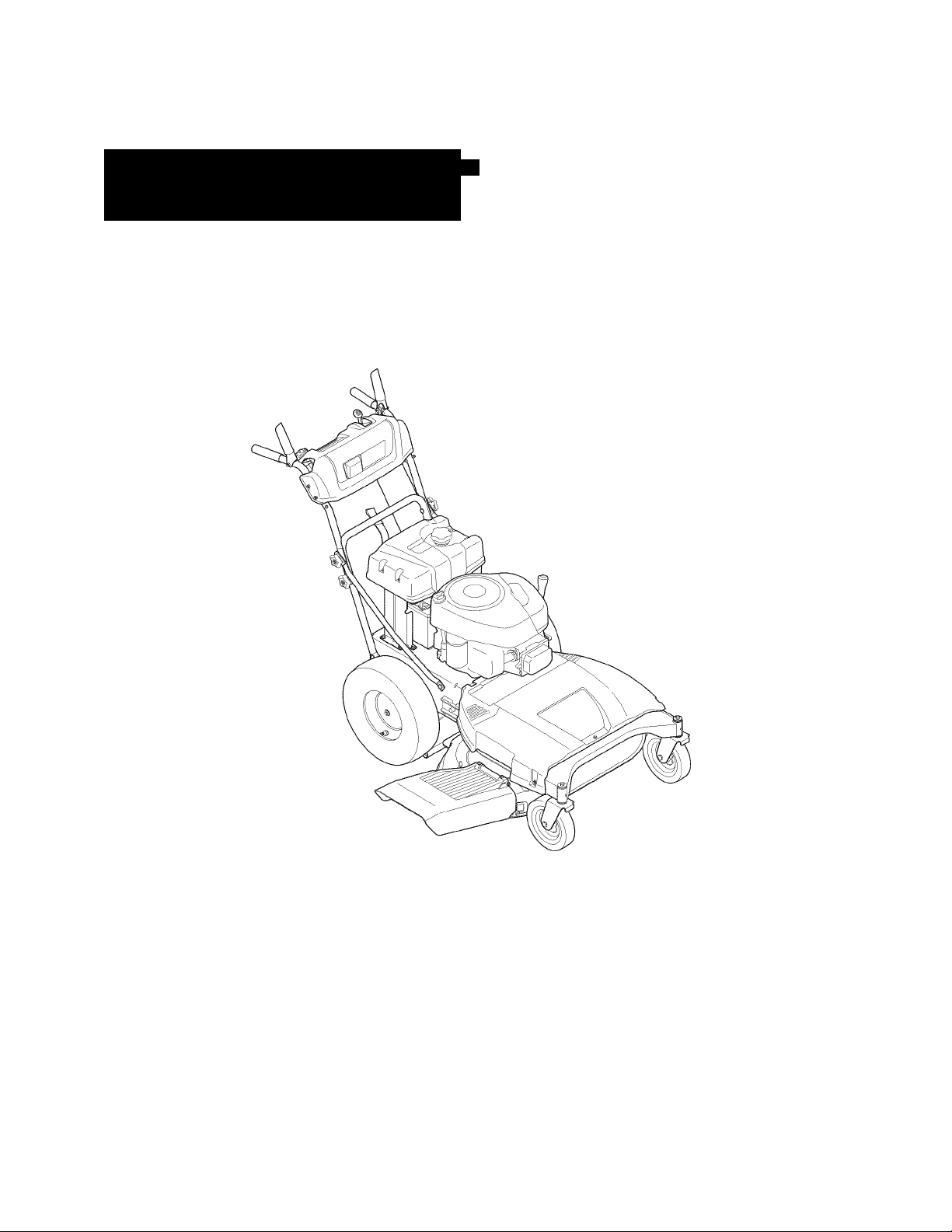
33-inch Wide Cut Mower
Model No. 247.889980
®
For answers to your questions about this product,
call 1-800-4iViY-HOiViE.
CAUTION: Before using this
product, read this manual and
follow ail safety rules and operating
instructions.
Sears, Roebuck and Co., Hoffman Estates, IL 60179, U.S.A.
Visit our website: www.sears.com/craftsman ,
SAFETY
ASSEMBLY
OPERATION
MAINTENANCE
PARTS LIST
ESPAÑOL P. 48
Form No. 769-04684A
(December 21,2009)
Page 2

TABLE OF CONTENTS
Warranty Statement...............................................................2
Safety Instructions.................................................................3
Slope Guide......................................................................5
Safety Labels....................................................................6
Assembly..........................................................................8
Know your Lawn Mower.......................................................11
Operation..............................................................................14
Service and Maintenance ...................................................16
Off-Season Storage.............................................................26
Accessories and Attachments
Troubieshooting...................................................................27
Parts List..............................................................................28
Españoi................................................................................48
Service Numbers
..................................................
.............................................
Back Oover
26
WARRANTY STATEMENT
CRAFTSMAN PROFESSIONAL FULL WARRANTY
When operated and maintained according to all supplied instructions, it this Craftsman Professional product fails due to a defect in material or
workmanship within two years from the date or purchase, call 1-800-4-MY-HOME® to arrange for free repair (or replacement it repair proves
impossible).
This warranty applies for only one year from the date of purchase it this product is ever used for commercial or rental purposes.
This warranty covers ONLY defects in material and workmanship. Sears will NOT pay for:
• Expendable items that become worn during normal use, including but not limited to blades, spark plugs, air cleaners, belts, and oil filters.
• Standard maintenance servicing, oil changes, or tune-ups.
• Tire replacement or repair caused by punctures from outside objects, such as nails, thorns, stumps, or glass.
• Tire or wheel replacement or repair resulting from normal wear, accident, or improper operation or maintenance.
• Repairs necessary because of operator abuse, including but not limited to damage caused by impacting objects that bend the frame or
crankshaft, or over-speeding the engine.
• Repairs necessary because of operator negligence, including but not limited to, electrical and mechanical damage caused by improper
storage, failure to use the proper grade and amount of engine oil, failure to keep the deck clear of flammable debris, or failure to maintain the
equipment according to the instructions contained in the operator's manual.
• Engine (fuel system) cleaning or repairs caused by fuel determined to be contaminated or oxidized (stale). In general, fuel should be used
within 30 days of its purchase date.
• Normal deterioration and wear of the exterior finishes, or product label replacement.
This warranty applies only while this product is within the United States.
This warranty gives you specific legal rights, and you may also have other rights which vary from state to state.
Sears, Roebuck and Co., Hoffman Estates, IL 60179
PRODUCT SPECIFICATIONS
Gross HP: 12.5
Engine Oil: SAE 30
Fuel: Unleaded Gasoline
Spark Plug: Champion® RC12YC
Engine: Briggs & Stratton PowerBuilt™
§ Sears Brands, LLC
MODEL NUMBER
Model Number__
Serial Number
Date of Purchase
__
Record the model number, serial number,
and date of purchase above.
Page 3

SAFETY INSTRUCTIONS
J
Awarning
This symbol points out important safety instructions
which, if not followed, could endanger the personal
safety and/or property of yourself and others. Read
A
and follow all instructions in this manual before
attempting to operate this machine. Failure to comply with these
instructions may result in personal injury. When you see this symbol,
HEED ITS WARNING!
Your Responsibility:
Restrict the use of this power machine to
persons who read, understand, and follow the warnings and instruc
tions in this manual and on the machine.
CHILDREN
Tragic accidents can occur if operator is not alert to presence of children. Chil
dren are often attracted to mower and mowing activity. They do not understand
the dangers. Never assume that children will remain where you last saw them.
• Keep children out of the mowing area and under watchful care of a
responsible adult other than the operator.
• Be alert and turn mower off if a child enters the area.
• Before and while moving backwards, look behind and down for small
children.
• Use extreme care when approaching blind corners, doorways, shrubs,
trees, or other objects that may obscure your vision of a child who may
run into the mower.
• Keep children away from hot or running engines. They can suffer burns
from a hot muffler.
• Never allow children under 14 years old to operate a power mower.
Children 14 years old and over should read and understand operation
instructions and safety rules in this manual and should be trained and
supervised by a parent.
GENERAL OPERATION
• Read this operator’s manual carefully in its entirety before attempting
to assemble this machine. Read, understand, and follow all instructions
on the machine and in the manual(s) before operation. Be completely
familiar with the controls and the proper use of this machine before
operating it. Keep this manual in a safe place for future and regular
reference and for ordering replacement parts.
• This machine is a precision piece of power equipment, not a plaything.
Therefore, exercise extreme caution at all times. Your unit has been
designed to perform one job: to mow grass. Do not use it for any other
purpose.
• Never allow children under 14 years old to operate this machine.
Children 14 years old and over should read and understand the instruc
tions in this manual and should be trained and supervised by a parent.
Only responsible individuals who are familiar with these rules of safe
operation should be allowed to use this machine.
• Thoroughly inspect the area where the equipment is to be used. Remove
all stones, sticks, wire, bones, toys and other foreign objects which could
be tripped over or picked up and thrown by the blade. Thrown objects
can cause serious personal injury. Plan your mowing pattern to avoid
discharge of material toward roads, sidewalks, bystanders and the like.
Also, avoid discharging material against a wall or obstruction which may
cause discharged material to ricochet back toward the operator.
This machine was built to be operated according to the rules tor
safe operation in this manual. As with any type of power equipment,
carelessness or error on the part of the operator can result in serious
injury. This machine is capable of amputating hands and feet and
throwing objects. Failure to observe the following safety instructions
could result in serious injury or death.
Engine Exhaust, some of its constituents, and certain vehicle
components contain or emit chemicals known to State of California to
cause cancer and birth defects or other reproductive harm.
A DANGER
AWARNING
To help avoid blade contact or a thrown object injury, stay in operator
zone behind handles and keep children, bystanders, helpers, and pets at
least 75 feet from mower while it is in operation. Stop machine if anyone
enters area.
Always wear safety glasses or safety goggles during operation and while
performing an adjustment or repair to protect your eyes. Thrown objects
which ricochet can cause serious injury to the eyes.
Wear sturdy, rough-soled work shoes and close-fitting slacks and shirts.
Shirts and pants that cover the arms and legs and steel-toed shoes
are recommended. Never operate this machine in bare feet, sandals,
slippery or light weight (e.g. canvas) shoes.
Do not put hands or feet near rotating parts or under cutting deck.
Contact with blade can amputate hands and feet.
A missing or damaged discharge cover can cause blade contact or
thrown object injuries.
Many injuries occur as a result of the mower being pulled over the foot
during a fall caused by slipping or tripping. Do not hold on to the mower if
you are falling; release the handle immediately.
Never pull the mower back toward you while you are walking. If you must
back the mower away from a wall or obstruction first look down and
behind to avoid tripping and then follow these steps:
a. Step back from mower to fully extend your arms.
b. Be sure you are well balanced with sure footing.
c. Pull back slowly, no more than half way towards you.
d. Repeat these steps as needed.
Do not operate the mower while under the influence of alcohol or drugs.
Do not engage the self-propelled mechanism on units so equipped while
starting engine.
The blade control handle is a safety device. Never attempt to bypass its
operation. Doing so makes the safety device inoperative and may result
in personal injury through contact with the rotating blade. The blade
control handle must operate easily in both directions and automatically
return to the disengaged position when released.
Never operate the mower in wet grass. Always be sure of your footing. A
slip and fall can cause serious personal injury. If you feel you are losing
your footing, release the blade control handle immediately and the blade
will stop rotating within three seconds.
Mow only in daylight or good artificial light. Walk, never run.
Stop the blade when crossing gravel drives, walks or roads.
Page 4

SAFETY INSTRUCTIONS
• If the equipment should start to vibrate abnormally, stop the engine and
check immediately for the cause. Vibration is generally a warning of
trouble.
• Shut the engine off and wait until the blade comes to a complete stop
before removing the grass catcher or unclogging the chute.
The cutting blade continues to rotate for a few seconds after the engine
is shut off. Never place any part of the body in the blade area until you
are sure the blade has stopped rotating.
• Never operate mower without proper trailshield, discharge cover, grass
catcher, blade control handle, or other safety protective devices in place
and working. Never operate mower with damaged safety devices. Failure
to do so can result in personal injury.
• Muffler and engine become hot and can cause a burn. Do not touch.
• Only use parts and accessories made for this machine by manufacturer.
Failure to do so can result in personal injury. For recommended acces
sories, call 1-800-659-5917.
• If situations occur which are not covered in this manual, use care and
good judgment. Contact your Sears Service Center for assistance.
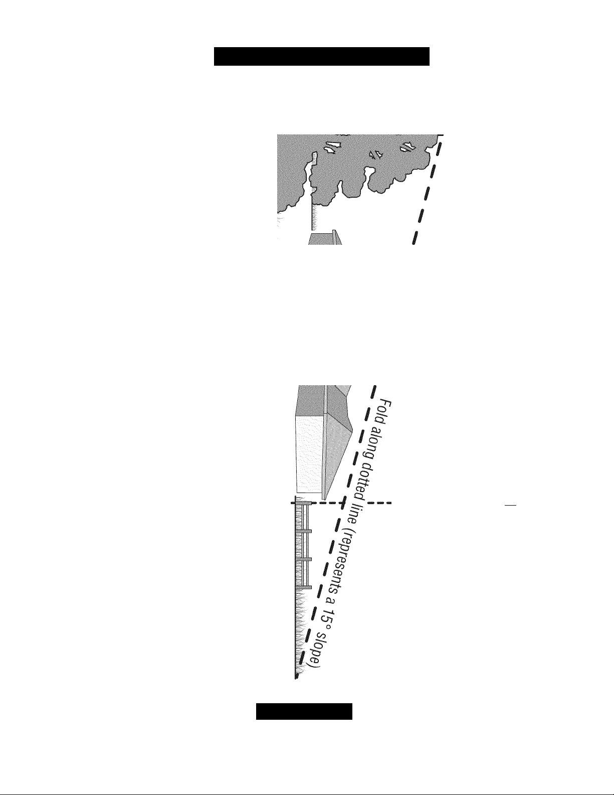
SLOPE OPERATION
Slopes are a major factor related to slip and fall accidents which can result in
severe injury. Operation on slopes requires extra caution. If you feel uneasy on
a slope, do not mow it. For your safety, use the slope guide included as part of
this manual to measure slopes before operating this unit on a sloped or hilly
area. If the slope is greater than 15 degrees, do not mow it.
Do:
• Mow across the face of slopes; never up and down. Exercise extreme
caution when changing direction on slopes.
• Watch for holes, ruts, rocks, hidden objects, or bumps which can cause
you to slip or trip. Tall grass can hide obstacles.
• Always be sure of your footing. A slip and fall can cause serious personal
injury. If you feel you are losing your balance, release the blade control
handle immediately, and the blade will stop rotating within 3 seconds.
Do Not:
• Do not mow near drop-offs, ditches or embankments, where you could
lose your footing or balance.
• Do not mow slopes greater than 15 degrees as shown on the
slope gauge.
• Do not mow on wet grass. Unstable footing could cause slipping.
SERVICE
Safe Handling Of Gasoline;
• To avoid personal injury or property damage use extreme care in
handling gasoline. Gasoline is extremely flammable and the vapors are
explosive. Serious personal injury can occur when gasoline is spilled on
yourself or your clothes which can ignite.
• Wash your skin and change clothes immediately.
• Use only an approved gasoline container.
• Never fill containers inside a vehicle or on a truck or trailer bed with a
plastic liner. Always place containers on the ground away from your
vehicle before filling.
• Remove gas-powered equipment from the truck or trailer and refuel it on
the ground. If this is not possible, then refuel such equipment on a trailer
with a portable container, rather than from a gasoline dispenser nozzle.
• Keep the nozzle in contact with the rim of the fuel tank or container
opening at all times until fueling is complete. Do not use a nozzle
lock-open device.
• Extinguish all cigarettes, cigars, pipes and other sources
of ignition.
• Never fuel machine indoors because flammable vapors will accumulate
in the area.
Never remove gas cap or add fuel while engine is hot or running.
Allow engine to cool at least two minutes before refueling.
Never over fill fuel tank. Fill tank to no more than '/2 inch below bottom
of filler neck to provide for fuel expansion.
Replace gasoline cap and tighten securely.
If gasoline is spilled, wipe it off the engine and equipment. Move unit
to another area. Wait 5 minutes before starting engine.
Never store the machine or fuel container near an open flame, spark
or pilot light as on a water heater, space heater, furnace, clothes dryer,
or other gas appliances.
To reduce fire hazard, keep mower free of grass, leaves, or other
debris build-up. Clean up oil or fuel spillage and remove any fuel
soaked debris.
Allow a mower to cool at least 5 minutes before storing.
General Service:
Never run an engine indoors or in a poorly ventilated area. Engine
exhaust contains carbon monoxide, an odorless and deadly gas.
Before cleaning, repairing, or inspecting, make certain the blade and
all moving parts have stopped. Disconnect the spark plug wire and
ground against the engine to prevent unintended starting.
Check the blade and engine mounting bolts at frequent intervals for
proper tightness. Also, visually inspect blade for damage (e.g., bent,
cracked, worn) Replace blade with the original equipment manufac
ture’s (O.E.M.) blade only, listed in this manual. Use of parts which do
not meet the original equipment specifications may lead to improper
performance and compromise safety!
Mower blades are sharp and can cut. Wrap the blade or wear gloves,
and use extra caution when servicing them.
Keep all nuts, bolts, and screws tight to be sure the equipment is in
safe working condition.
Never tamper with safety devices. Check their proper
operation regularly.
After striking a foreign object, stop the engine, disconnect the spark
plug wire and ground against the engine. Thoroughly inspect the
mower for any damage. Repair the damage before starting and
operating the mower.
Never attempt to make a wheel or cutting height adjustment while the
engine is running.
Grass catcher components, discharge cover, and trailshield are
subject to wear and damage which could expose moving parts or
allow objects to be thrown. For safety protection, frequently check
components and replace immediately with original equipment
manufacturer’s (O.E.M.) parts only, listed in this manual. Use of parts
which do not meet the original equipment specifications may lead to
improper performance and compromise safety!
Do not change the engine governor setting or overspeed the engine.
The governor controls the maximum safe operating speed of the
engine.
Maintain or replace safety labels, as necessary.
Observe proper disposal laws and regulations. Improper disposal of
fluids and materials can harm the environment.
Page 5
SAFETY INSTRUCTIONS
J
Use this page as a guide to determine slopes where you may
not
operate safely.
Do not operate
I
the lawn mower on such slopes.
cq'
zr
1 i
CD
Z5
I
I
/
I
O.
ZT
o_
CL
1 i
C/>‘
cd"
<
CD
/
CD
<
CD
o’
CD
CD
o o
o
=3
o
< 3
5 ^
[“ o
CD 5’
m o
3
E-
o zr
^ C/>
^ o
CD T3
q CD
O
C/) ^
C/> CD
^ X
zr o
CD CD
S' «
S a
O
CJ1
Q.
CD
CQ
O
CD
O
03 -K
=3 SD
CL T3
CL
O O
cn 03
~ o
Ig
c/> ro
3
CD
CD
CD
CD
o
o
CD
TD
O
00
CD
o
o
CD
O
O"
zs'
(O
AWARNING
This symbol points out important safety instructions which, it not followed, could endanger the personal safety and/or property of yourself and
others. Read and follow all instructions in this manual before attempting to operate this machine. Failure to comply with these instructions may
result in personal injury. When you see this symbol, HEED ITS WARNING!
Page 6

SAFETY LABELS
DO NOT OPERATE UNLESS AN UNDAMAGED D ISCHARGE
COVER OR ENTIRE GRASS CATCHER IS IN PLACE .
I
WARNING
This symbol points out important safety instructions
which, if not followed, could endanger the personal
safety and/or property of yourself and others. Read and
follow all instructions in this manual before attempting
to operate this machine. Failure to comply with these
instructions may result in personal injury. When you see
this symbol
Your Responsibility
Restrict the use of this power machine to persons who
read, understand, and follow the warnings and instruc
tions in this manual and on the machine.
HEED ITS WARNING!
avoid
•ROTATING PARTS
l№ THAN 15 •. MOW ACROSSj^N^w
iun f down, look down and behind before
WD WHILE MOVING BACKWARDS.
cn.fi "i^WUAL.
COVER TrnZ- SAFETY DEVICES (BLADE
A DANGER
serious injury or death
and feet away from
AREarouno CHILDREN OR OTHERS
CAUTION ON SLOPES. DO NOT MOW
AND WORKING. IF DAMAGED^R^^
Page 7

This page left intentionally blank.
Page 8
ASSEMBLY
IMPORTANT: This unit is shipped with oil in the engine. After
assembly, see page 12 for fuel and oil details.
IMPORTANT: Reference to right or left side of the mower is observed
from the operating position.
A WARNING
Disconnect the spark plug wire and ground it against
prevent unintended starting.
LOOSE PARTS IN CARTON
The following items are packaged in a bag:
Operator’s Manual, Oil drain hose. Water hose coupler. Engine Manual
TOOLS NEEDED FOR ASSEMBLY
A set of adjustable wrenches and tire gauge
MOWER SET-UP Shipping Brace Removal
the engine to
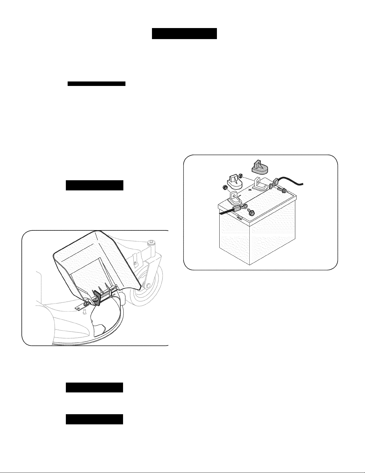
Attaching the Battery Cables
NOTE: The positive battery terminal is marked Pos. (■+•). The negative
battery terminal is marked Neg. (-).
The positive cable (heavy red wire) is secured to the positive battery
terminal (■+•) with a hex bolt and hex nut at the factory.
The negative cable (heavy black wire) may be secured to the negative
battery terminal at the factory. If it hasn’t been attached, proceed as
follows:
1. Remove the carriage bolt and hex nut from the positive cable
(heavy red wire).
2. Remove the red plastic cover, it present, from the positive battery
terminal and attach the positive cable to the positive battery
terminal (■+•) with the bolt and hex nut. See Figure 2.
AWARNING
Make sure the lawn mower’s engine is off. Remove the ignition key
before removing the shipping brace.
1. Locate the shipping brace, it present, found on the right side of
the cutting deck. See Figure 1.
3. Remove the carriage bolt and hex nut from the negative cable
4. Remove the black plastic cover, it present, from the negative bat
5. Make certain the hold-down rod is in position over the battery,
Figure 1
2. While holding the discharge chute with your left hand, remove the
shipping brace with your right hand by grasping it between your
thumb and index finger and rotating it clockwise.
AWARNING
The shipping brace is used for packaging purposes only. Remove
and discard the shipping brace before operating your lawn mower.
AWARNING
The mowing deck is capable of throwing objects. Failure to operate
the mower without the discharge cover in the proper operating posi
tion could result in serious personal injury and/or property damage.
Figure 2
(heavy black wire).
tery terminal and attach the negative cable to the negative battery
terminal (-) with the bolt and hex nut. See Figure 2.
securing it in place and make certain that the red rubber boot cov
ers the positive battery terminal to help protect it from corrosion.
NOTE: If the battery is put into service after the date shown
on top/side of battery, charge the battery as instructed in the
Maintenance section of this manual prior to operating the mower.
Page 9
ASSEMBLY
J
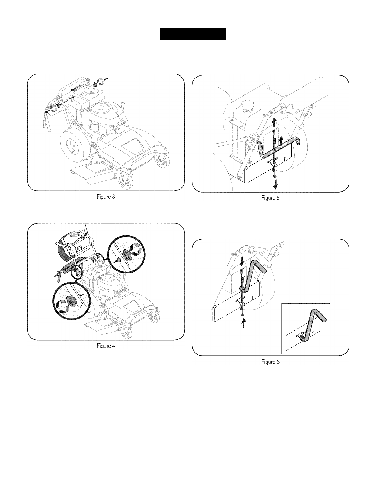
Unfolding the Handle
1. Remove the star knobs and carriage screws from the lower
handle. See Figure 3.
2. Pivot the upper handle into operating position. Be careful not to
crimp cables. See Figure 4.
Attaching the Shift Lever
1. Remove the screw and the lock nut that secures the shift lever to
the shift lever plate. See Figure 5.
2. Remove the remaining screw and nut from the lower shift lever
plate. See Figure 5.
3. Position the upper shift lever into a vertical position aligning the
holes in the lever with the holes in the shift plate. See Figure 6.
3. Reinstall the carriage screws and knobs removed earlier.
4. Tighten the upper and lower star knobs and carriage screws to
secure the upper handle to the lower handle, See Figure 4.
5. The handle height can be adjusted to any of three positions.
For instructions, refer to Handle Height in the Maintenance and
Adjustments section of this manual.
4. Secure the lever to the plate using the two screws and two nuts
removed earlier. See Figure 6.
Page 10

ASSEMBL
Checking Tire Pressure
AWARNING
Maximum tire pressure under any circumstances is 30 psi. Equal tire
pressure should be maintained at all times.
The rear tires on your unit may be over-inflated for shipping purposes.
Reduce the tire pressure before operating the mower. Recommended
operating tire pressure is approximately 20 p.s.i. Check the sidewall of
tire for maximum p.s.i.
Gas and Oil
The fuel tank has a capacity of two gallons. Remove the fuel cap by
turning it counterclockwise. Use only clean, fresh (no more than 30
days old), unleaded gasoline. Fill the tank no higher than four inches
below the top of the filler neck to allow space for fuel expansion.
AWARNING
Use extreme care when handling gasoline. Gasoline is extremely
flammable and the vapors are explosive. Never fuel the machine
indoors or while the engine is hot or running. Extinguish cigarettes,
cigars, pipes and other sources of ignition.
I
NOTE: Your lawn mower is shipped with oil in the engine. However,
you MUST check the oil level before operating. Refer to the Service
and Maintenance Section for Check Oil instructions.
A CAUTION
Always check the engine oil level before each use. Add oil as neces
sary. Failure to do so may result in serious damage to your engine.
10
Page 11
KNOW YOUR MOWER
Spark Plug
Refer to the Maintenance section for instructions on spark plug
replacement.
Oil Cap/Dipstick
Refer to the Maintenance section for instructions on checking the oil.
MOWER CONTROLS
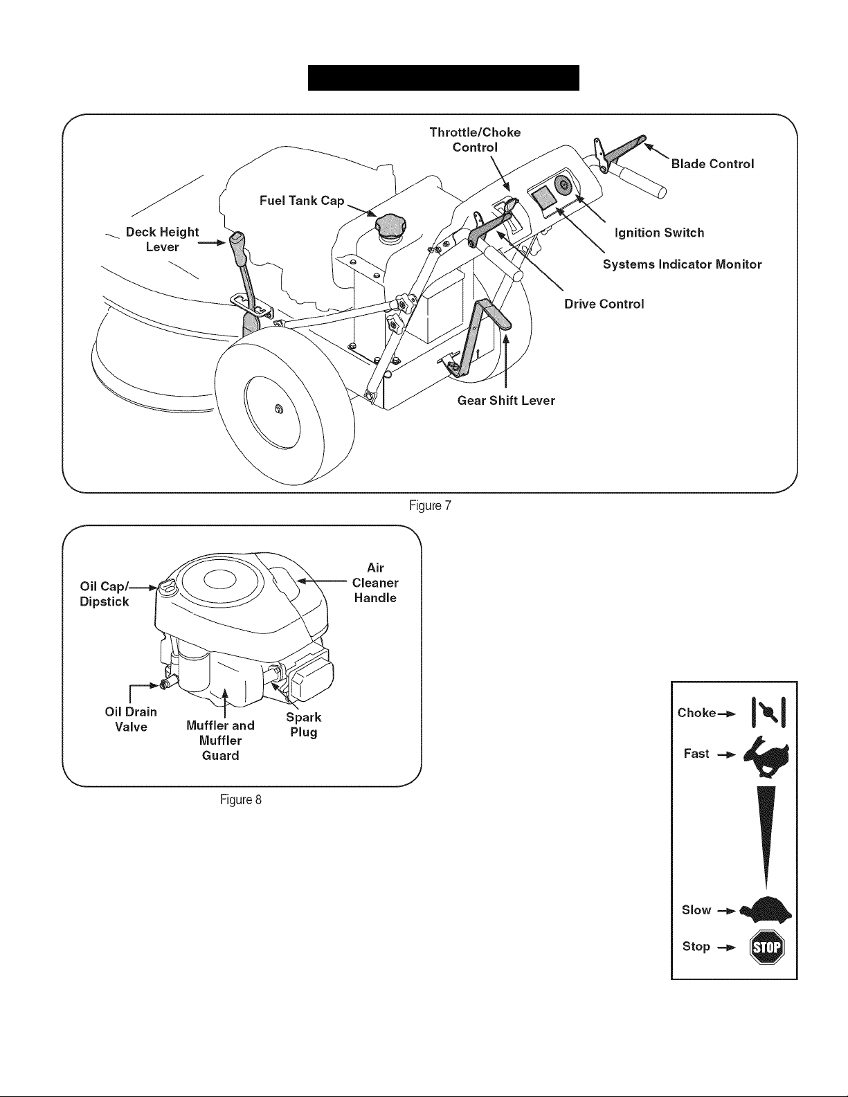
Refer to Figure 7 for locations of the mower controls.
Throttle/Choke Control
NOTE: When operating the mower with the
cutting deck engaged, be certain that the
throttle/choke control is in the fast position.
THE throttle/choke control is used to adjust
engine speeds, to activate the engine choke
and to stop the engine. Always run engine
ENGINE CONTROLS
Refer to Figure 8 for locations of the
Oil Drain Valve
Use the oil drain valve to drain oil from the engine. Refer to the
Maintenance section for instructions.
Air Cleaner Handle
The air cleaner handle is used to gain access to the air cleaner. The air
cleaner cartridge can be removed and cleaned or replaced. Refer to
the Maintenance section for details.
engine
controls.
with the throttle / choke control lever in the
fast position for best mower performance.
CHOKE: Use when starting a cold engine.
FAST: Use during mower operation.
SLOW: Use when idling engine.
STOP: Stops the engine.
REFER to Starting The Engine in the
Operation section of this manual for detailed
starting instructions.
11
Page 12
KNOW YOUR MOWER
J
Deck Height Lever
Use this lever to adjust the mowing deck’s cutting height. To use, move
the lever to the left, then place the lever in the notch best suited for
your application.
Drive Control
The drive control is used to engage and
disengage drive to the wheels. To engage
this control, squeeze the drive control
against the handlebar grip. To stop the drive.
release the drive control.
HEIGHT ADJUSTER
J
L I
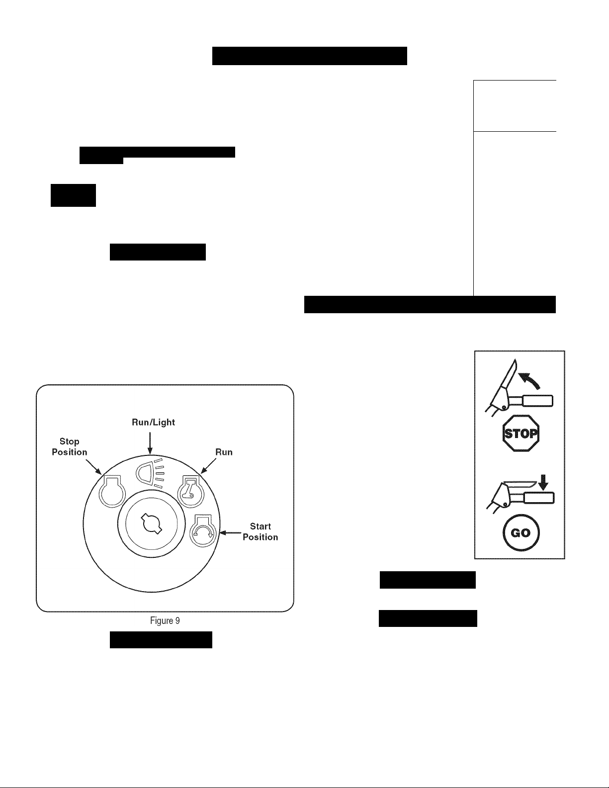
Ignition Switch
ih
AWARNING
Never leave a running machine unattended. Always disengage
blades, stop engine and remove key to prevent unintended starting.
The four-position switch is used to start and stop the engine on
electric-start models. To start the engine, insert the key into the
ignition switch and turn clockwise to the START (Q) position.
Release key into the RUN (^) position once the engine has started.
Move the key into the RUN/LIGHT position to run the mower
with the headlight on. Turn the key to STOP to stop the engine.
See Figure 9.
Always release the drive control before changing speeds. Failure to
do so may result in serious damage to your transmission.
Blade Control
Located on the right-hand handle, the blade
control is used to engage the mowing deck.
To operate, press and hold the lever against
the handlebar grip. To stop the blades,
release the blade control.
A
CAUTION
I—
I
--------
0
k
1
Never attempt to start the engine with the blade control engaged.
A
CAUTION
Never move the key into the Start position while the engine is running;
doing so may cause damage to the engine’s starter.
Always release the blade control when starting the engine. Failure to
do so may result in premature wear to your engine’s electric starter.
12
AWARNING
A
CAUTION
Page 13
KNOW YOUR MOWER
J
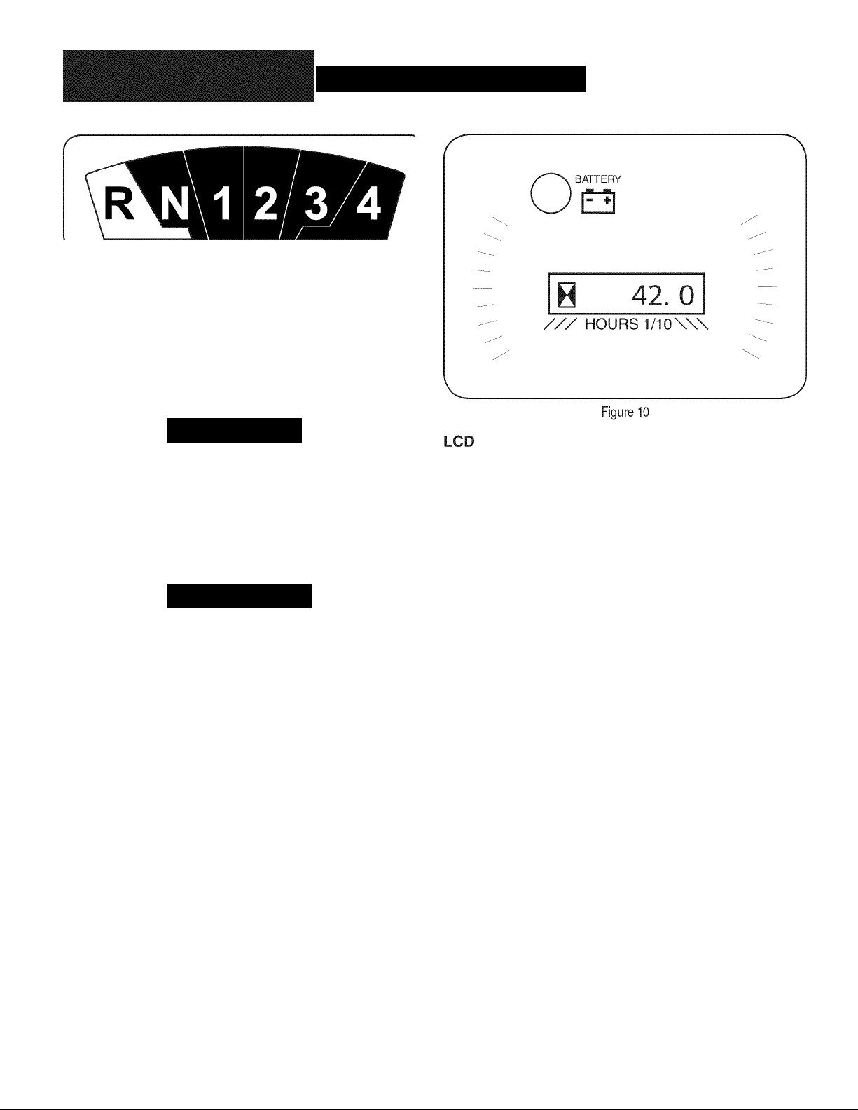
GEAR SHIFT LEVER
Use this lever to select any of four forward ground speeds, neutral, or
reverse.
Forward
Four forward speeds are available. Position one (1) is the slowest and
position four (4) is the fastest.
Reverse
To select reverse, put the lever in the Reverse (R) position.
SYSTEMS INDICATOR MONITOR/HOUR METER
AWARNING
Look behind the mower before and during reverse operation. Stop the
mower blades before operating in reverse.
Neutral
Place the lever in neutral (N) before starting the mower and when the
mower is not in use. In addition, the mower can be manually pushed
or pulled by placing the gear shift lever into N (neutral) position and
pressing the drive control against the handlebar grip.
A
CAUTION
Always release the drive control before changing speeds. Failure to
do so may result in serious damage to your transmission.
When the ignition key is rotated out of the STOP position but not
into the START position, the systems indicator monitor displays the
battery’s output, in volts, on its LCD tor approximately five seconds,
after which it displays an hour glass and the hours of mower operation.
Once the engine is started, the monitor continually displays an hour
glass and the hours of mower operation on its LCD. See Figure 10.
NOTE: Flours of mower operation are recorded any time the ignition
key is rotated out of the STOP position, regardless of whether the
engine is started.
The Indicator Monitor will also remind the operator of maintenance
intervals for changing the engine oil. The LCD will alternately flash the
recorded hours, “CHG ” and “OIL” for five minutes, after every 50 hours
of recorded operation elapse. The maintenance interval lasts for two
hours (from 50-52, 100-102, 150-152, etc.). The LCD will also flash
as described above for five minutes every time the mower’s engine
has been started during this maintenance interval. Before the interval
expires, change the engine oil as instructed in the Maintenance section
of this Operator’s Manual.
Battery
It is normal for the Battery light to illuminate while the engine is
cranking during start-up, but if it illuminates during operation, while the
engine is running, the battery is in need of a charge or the engine’s
charging system is not generating sufficient amperage. Charge the
battery as instructed in the Service section of this manual or have the
charging system checked by Sears or another qualified service dealer.
13
Page 14

OPERATION
STARTING THE ENGINE
Refer to the Service and Maintenance section of this manual for
Gasoline and Oil fill-up instructions.
1. Disengage all controls on the mower.
2. Move the gear shift lever into the neutral (N) position.
3. Insert the key into the ignition switch.
4. If starting a cold engine, place the throttle/choke control all the
way forward, into the CHOKE
engine, place the throttle/choke control into the Fast V position.
5. Turn the ignition key clockwise to the START (Q) position. After
the engine starts, release the key. It will return to the RUN
position.
6. Move the key to the RUN/LIGHT position to operate the
mower using the headlight. ""
|x|
position. If restarting a warm
^
To travel in REVERSE,
Do NOT attempt to change the direction of travel when the mower is
in motion. Always release the drive control and bring the mower to a
complete stop before repositioning the gear shift lever from a forward
gear into Reverse. Failure to do so may result in serious damage to
your transmission.
Do not leave the operator’s position without first releasing the Blade
Control. If leaving the mower unattended, also turn the engine off and
remove the ignition key.
A CAUTION
Do NOT hold the key in the START position for longer than five
seconds at a time. Doing so may cause damage to your engine’s
electric starter.
7. Move the throttle/choke control into the FAST position.
NOTE: Never leave the throttle/choke control in the CHOKE M
position while operating the mower. Doing so will result in a “rich” fuel
mixture and cause the engine to run poorly.
Stopping the Engine
ENGAGING THE BLADES
To help avoid blade contact or a thrown object injury, keep bystand
ers, helpers, children and pets at least 75 feet from the machine while
it is in operation. Stop machine it anyone enters the area.
1. Move the throttle/choke control to the FAST ^ position.
2. Slowly squeeze the Blade Control against the right handle grip
a. Check that the area behind is clear.
b. Place the gear shift lever in Reverse (R).
c. Slowly squeeze the Drive Control against the left handle grip
and the mower will move. Release it and drive motion will stop.
A CAUTION
AWARNING
AWARNING
and the blades will engage. Release it and the blades will stop.
AWARNING
If you strike a foreign object, stop the engine and remove the ignition
key. Thoroughly inspect the machine for any damage. Repair the
damage before restarting and operating.
1. If the blades are engaged, release the Blade Control.
2. Move the throttle/choke control into the STOP @ position.
3. Turn the ignition key counterclockwise to the STOP iQ) position.
4. Remove the key from the ignition switch to prevent unintended
starting.
ENGAGING THE DRIVE
______________________
OPERATING ON SLOPES
Refer to the SLOPE GUIDE on page 5 to help determine slopes where
you may operate the mower safely.
Do not mow on inclines with a slope in excess of 15 degrees (a rise
of
and cause serious injury.
AWARNING
I
Avoid sudden starts, excessive speed and sudden stops.
Start the engine as instructed earlier in this section and move the
throttle/choke control into the FAST
To travel FORWARD:
a. Place the gear shift lever in any of the four forward ground
speeds. Select a speed appropriate for the conditions and a
pace you're comfortable with.
b. Slowly squeeze the Drive Control against the left handle grip
and the mower will move. Release it and drive motion will stop.
^
position.
___________
|
AWARNING
approximately 2-1/2 feet every 10 feet). The mower could overturn
Mow across the face of slopes; never up and down.
Exercise extreme caution when changing direction on slopes.
Watch for holes, ruts, rocks, hidden objects, or bumps which can
cause you to slip or trip. Tall grass can hide obstacles.
Always be sure of your footing. A slip and fall can cause serious
personal injury. If you feel you are losing your balance, release
the blade control handle immediately and the blade will stop
rotating within three (3) seconds.
Do not mow near drop-offs, ditches or embankments, you could
lose your footing or balance.
Do not mow slopes greater than 15 degrees as shown on the
slope gauge.
Do not mow on wet grass. Unstable footing could cause slipping.
14
Page 15
OPERATION
USING THE DECK HEIGHT LEVER
To raise or lower the cutting deck, move the deck height lever to the
left, then place It in the notch best suited for your application.
MOWING
The following information will be helpful when operating your mower.
AWARNING
Plan your mowing pattern to avoid discharge of materials toward
roads, sidewalks, bystanders. Also, avoid discharging material
against a wall or obstruction which may cause discharged material to
ricochet back toward the operator.
Do not mow at fast ground speeds, especially it a mulch kit or
grass collector is installed.
Do not cut the grass too short. Short grass is prone to weed
growth and yellows quickly in dry weather.
Always operate the mower with the throttle/choke control in the
FAST
^ position while mowing.
For best results It is recommended that the first two laps be cut
with the discharge thrown towards the center. After the first two
laps, reverse the direction to throw the discharge to the outside
for the balance of cutting. This will give a better appearance to the
lawn.
Do NOT attempt to mow heavy brush and weeds or extremely tall
grass. Your mower is designed to mow lawns, NOT clear brush.
Keep the blades sharp and replace the blades when worn.
Before installing or removing the mulch baffle, disengage blades, stop
the engine and remove key to prevent unintended starting.
Stop the engine and wait for all parts to stop moving.
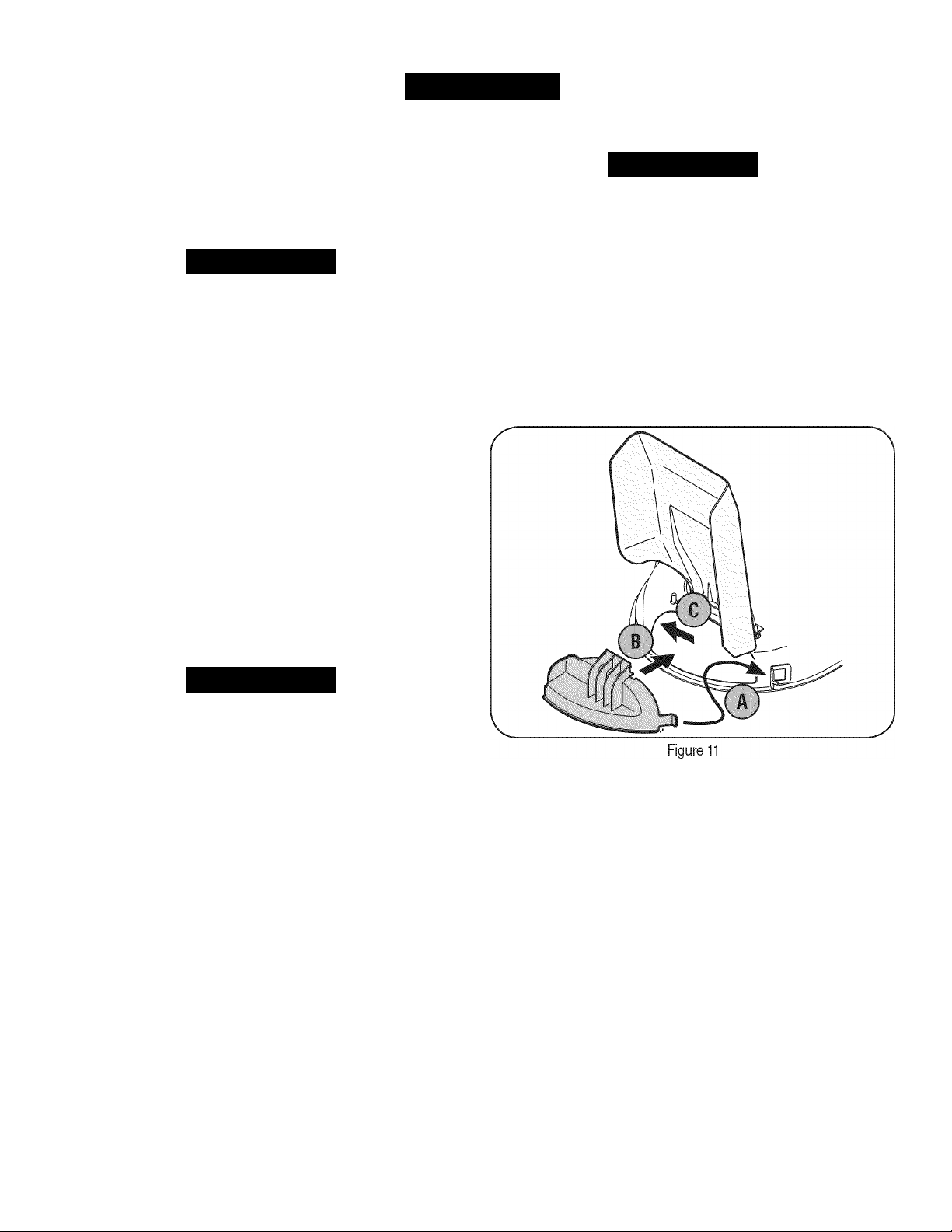
Installing the Mulch Baffle
1. Insert the right-side tab (A) of the baffle into the bracket on the
2. Insert the mulch baffle into the discharge opening (B). See
3. Once it's positioned in the deck opening, push the baffle towards
INSTALLING/REMOVING MULCH BAFFLE
AWARNING
deck. See Figure 11.
Figure 11.
the rear of the mower (C) to secure it in place.
See Figure 11.
AWARNING
After striking a foreign object, stop the engine, disconnect the spark
plug wire and ground against the engine. Thoroughly inspect the
mower for any damage. Always Inspect the blade timing belt as
instructed in the Maintenance section of this manual. Repair the
damage before starting and operating the mower.
MULCHING
The Craftsman Pro Wide Cut mower is equipped with a mulch kit (sup
plied with the mower), which uses special blades to recirculate grass
clippings repeatedly beneath the cutting deck. The ultra-fine clippings
are then forced back into the lawn where they act as a natural fertilizer.
Observe the following points for the best results when mulching.
• Never attempt to mulch it the lawn is damp. Wet grass tends
to stick to the underside of the cutting deck preventing proper
mulching of the clippings.
• Do NOT attempt to mulch more than 1/3 the total height of the
grass. Doing so will cause the clippings to clump up beneath the
deck and not be mulched effectively.
• Maintain a slow ground speed to allow the grass clippings more
time to effectively be mulched.
• Always keep the throttle control lever In the
while mowing. Failing to keep the engine at full throttle places
strain on the mower's engine and does not allow the blades to
properly mulch the grass clippings.
FAST
^ position
Removing the Mulch Baffle
Slide the baffle to the right (toward the front of the mower) to disen
gage the slot from the mower deck and then pry the left-side of the
baffle outward.
15
Page 16
SERVICE AND MAINTENANCE
MAINTENANCE
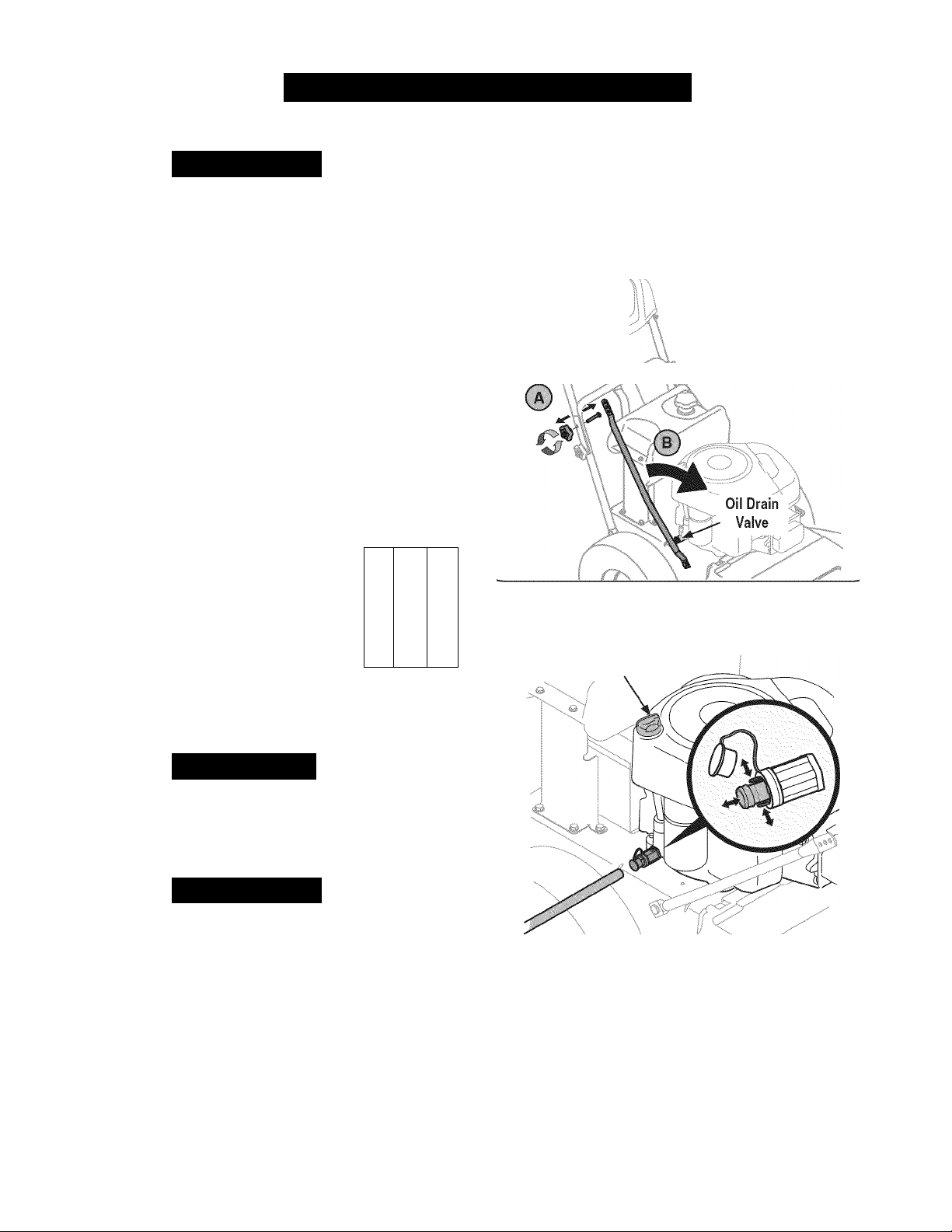
2. To gain access to the oil drain valve on the engine, pivot the right
AWARNING
Before performing any maintenance or repairs, disengage blades,
stop
engine
GENERAL RECOMMENDATIONS
• Always observe safety rules when performing any type of
maintenance on the mower.
• The warranty on this lawn mower does not cover items that have
been subjected to operator abuse or negligence. To receive full
value from warranty, operator must maintain the lawn mower as
instructed in this manual.
• Changing of engine-governed speed will void engine warranty.
• All adjustments should be checked
• Periodically check all fasteners and make sure they are tight.
ENGINE MAINTENANCE
Checking the Engine Oil
Check oil level before each use. Stop engine and wait several minutes
before checking oil level. With engine on level ground,
the oil must be to FULL mark on dipstick.
1. Remove the Oil Cap/Dipstick and wipe with a
clean cloth.
2. Replace and tighten Oil Cap/Dipstick. Remove
Oil Cap/Dipstick and check oil level. Level
should be at FULL mark.
3. If needed, add oil slowly into the engine oil'
Do not overfill.
4. Reinsert Oil Cap/Dipstick and tighten.
and remove key to prevent unintended starting.
at
least once each season.
-sxv
r“"\
Recheck oil level.
3. Pop off the protective cap on the end of the oil drain valve to
J
handle brace tube forward.
a. Remove the upper star knob and carriage screw on the right
side of the handle. Figure 12.
b. Pivot the brace tube towards the front of the mower to allow
room to connect the oil drain hose to the oil drain valve.
Figure 12.
Figure 12
expose the drain port. See Figure 13.
Oil Fill Cap/Dipstick
A
CAUTION
Do not overfill. Overfilling with oil may make the engine hard to start,
or not to start. If over the FULL mark on the dipstick, drain oil level to
FULL mark on dipstick.
Changing the Engine Oil
AWARNING
If the engine has been recently run, the engine, muffler and sur
rounding metal surfaces will be hot and can cause burns to the skin.
Exercise caution to avoid burns.
The oil in the engine should be changed after the first two hours of
operation and every 25 hours of operation.
1. Run the engine for a tew minutes to allow the oil in the crankcase
to warm up. Warm oil will flow more freely and carry away more of
the engine sediment which may have settled at the bottom of the
crankcase. Use care to avoid burns from hot oil.
4.
5.
16
Figure 13
Remove the oil fill cap/dipstick from the oil fill tube. Figure 13.
Push the oil drain hose (packed with this manual) onto the oil drain
port. Route the opposite end of the hose into an appropriate oil collec
tion container with at least a 2.5 quart capacity, to collect the used oil.
Release the valve by pressing the two tabs inward while pulling
the valve out. The oil will begin to drain out of the engine.
Page 17
SERVICE AND MAINTENANCE
J
7. After the oil has finished draining, press the two tabs inward and
push the oil drain valve back in to lock the valve closed. Remove
the hose, and re-cap the end of the oil drain valve to keep debris
from entering the drain port.
8. Refill the engine with new motor oil until the oil level on the
dipstick reads FULL. Replace the oil fill cap/dipstick.
9. Pivot the right handle brace tube back into position. Align the
middle hole in the brace tube with the hole in the handle. Secure
with the star knob and carriage screw removed earlier.
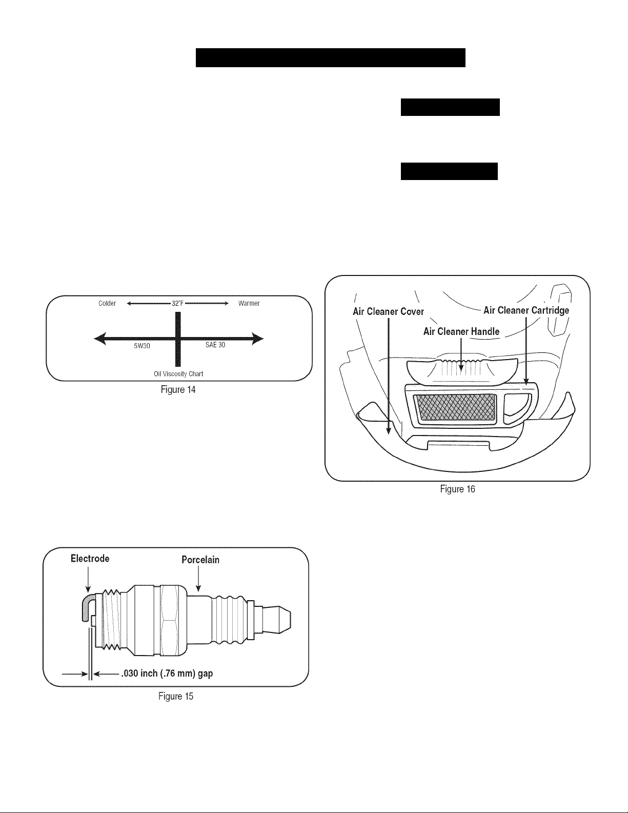
Only use high quality detergent oil rated with API service classification
SF or SG. Select the oil's SAE viscosity grade according to your
expected operating temperature. Figure 14. Although multi-viscosity
oils (5W30,10W30 etc.) improve starting in cold weather, these multi
viscosity oils will result in increased oil consumption when used above
32°F. Check your engine oil level more frequently to avoid possible
engine damage from running low on oil.
Servicing the Air Cleaner
If filters, or covers are not installed correctly serious injury or death
could result from backfire. Do not attempt to start the engine with
them removed.
Do not use pressurized air or solvents to clean the air cleaner
cartridge.
Clean or replace the air cleaner every 25 hours of operation.
1. Pull up on air cleaner handle. Figure 10, and pull back towards the
2. Remove the air cleaner cover. Figure 16.
AWARNING
A CAUTION
engine.
Checking the Spark Plug
Clean spark plug and reset the electrode gap to 0.030” at least once a
season; replace every 100 hours of operation.
1
.
Clean area around the spark plug base. Do not sandblast spark
plug. Spark plug should be cleaned by scraping or wire brushing
and washing with a commercial solvent
Remove and inspect the spark plug. Check gap to make sure it is
set at .030”. See Figure 15.
3.
Replace the spark plug it electrodes are pitted, burned, or the
porcelain is cracked. Use a Champion® RC12YC spark plug.
Carefully remove air cleaner cartridge and pre-cleaner (it
equipped) from the blower housing.
4.
Clean the base of the air cleaner cartridge carefully to prevent
debris from entering the engine.
Place the pre-cleaner, it equipped, and cartridge back into the
blower housing. The cartridge must be placed securely into
position.
Align tabs on cover with slots in blower housing and replace the
cover.
17
Page 18
SERVICE AND MAINTENANCE
BATTERY
1. Position the mower on a level, clear spot on your lawn, near
AWARNING
Battery posts, terminals, and related accessories contain lead and
lead compounds, chemicals known to the State of California to cause
cancer and reproductive harm. Wash hands after handling.
The battery is sealed and is maintenance-free. Acid levels cannot be
checked and fluid can not be added.
• Always keep the battery cables and terminals clean and free of
corrosive build-up.
• After cleaning the battery and terminals, apply a light coat of
petroleum jelly or grease to both terminals.
Make certain the mower’s discharge chute is directed AWAY from
your house, garage, parked cars, etc.
A CAUTION
If removing the battery for cleaning, disconnect the NEGATIVE (Black)
wire from it's terminal first, followed by the POSITIVE (Red) wire. When
re-installing the battery, always connect the POSITIVE (Red) wire its
terminal first, followed by the NEGATIVE (Black) wire. Be certain that
the wires are connected to the correct terminals; reversing them could
result in serious damage to your engine’s alternating system.
TIRE PRESSURE
AWARNING
Maximum tire pressure under any circumstances is 30 psi. Equal tire
pressure should be maintained at all times.
A CAUTION
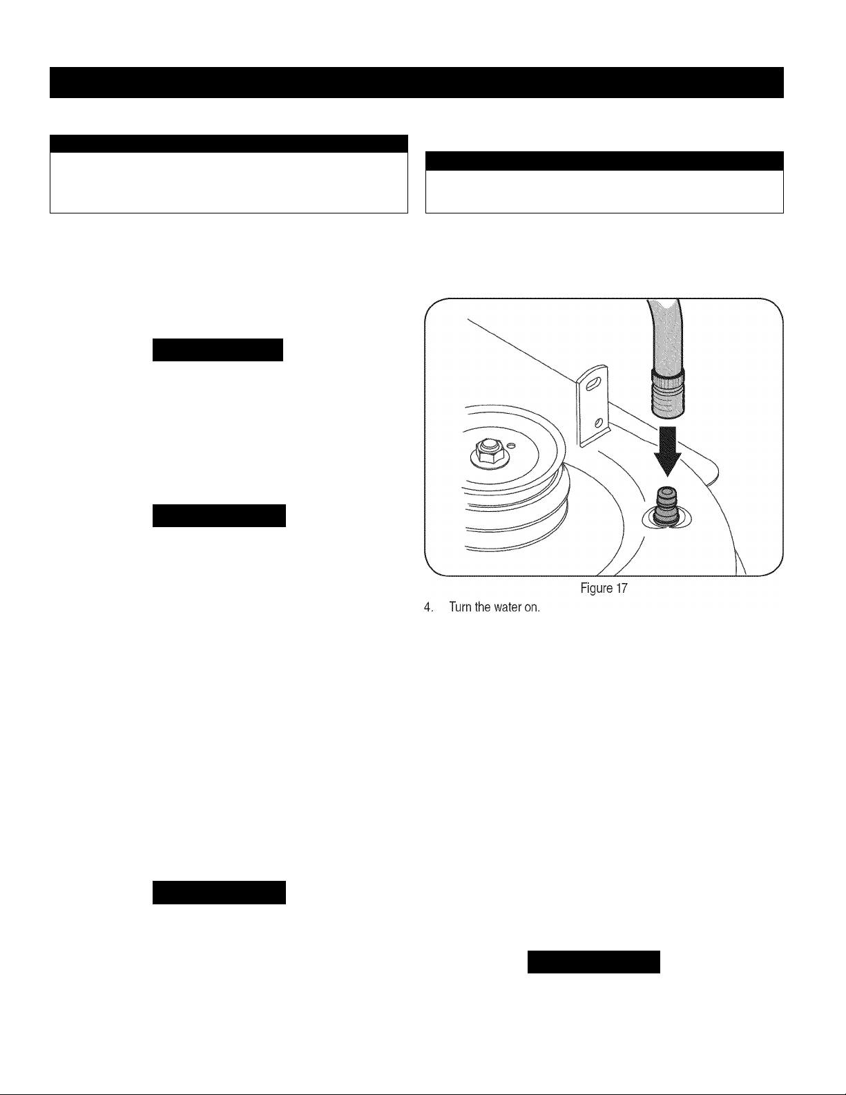
Thread the hose coupler (packaged with your mower’s Operator’s
Manual) onto the end of your garden hose.
Attach the hose coupler to the water port on the deck surface.
See Figure 17.
Periodically check the pressure on both your mower's rear tires.
Uneven tire pressure will cause the cutting deck to mow unevenly
and may result in mower to veering to either the left or right during
operation. Recommended operating tire pressure is approximately 20
p.s.i. Check the sidewall of tire for maximum p.s.i.
CLEANING THE MOWER
Any fuel or oil spilled on the machine should be wiped off promptly. Do
NOT allow debris to accumulate around the cooling fins of the engine,
the transmission’s cooling fan or on any other part of the machine,
especially the belts and pulleys.
Smart Jet
Your mower’s deck is equipped with a water port on its surface as part
of its deck wash system.
Use the Smart Jet to rinse grass clippings from the deck's underside
and prevent the buildup of corrosive chemicals. Complete the following
steps AFTER EACH MOWING:
AWARNING
Before using the deck wash system, always disengage the Blade
Control, stop engine and remove key to prevent unintended starting.
Start the engine and place the throttle lever in the FAST
position.
While in the operator’s position behind the mower, move the
Blade Control into the ON position.
Remain in the operator’s position with the cutting deck engaged
7.
fora minimum of two minutes, allowing the underside of the
cutting deck to thoroughly rinse.
Move the Blade Control into the OFF position.
8.
Turn the ignition key to the STOP position to turn the mower’s
9.
engine off.
Turn the water off and detach the hose coupler from the water
10.
port on your deck’s surface.
After cleaning your deck with the Smart Jet system, start the mower’s
engine, return to the operator’s position and engage the blades. Keep
the cutting deck running for a minimum of two minutes, allowing the
underside of the cutting deck to thoroughly dry.
LUBRICATION
Before lubricating, repairing, or inspecting, always disengage PTO,
set parking brake, stop engine and remove key to prevent unintended
starting.
40
AWARNING
18
Page 19
SERVICE AND MAINTENANCE
J
Pivot Points & Linkage
Lubricate all the pivot points on the drive system and lift linkage at
least once a season with light oil.
Rear Wheels
The rear wheels should be removed from the axles once a season.
Lubricate the axles and rim hubs well with an all-purpose grease
before reinstalling them.
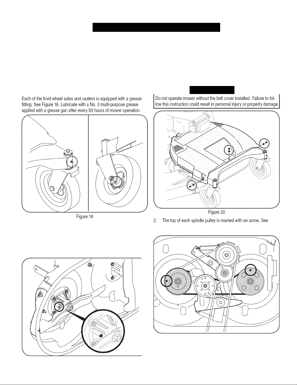
Front Wheels
BLADE TIMING BELT
The cutting deck spindles are driven by a timing (cogged) belt,
assuring that the deck blades are always perpendicular to each other.
At least once a season, or after striking any foreign object, check the
timing belt as follows:
1. Remove the belt cover by removing the three screws and washers
which secure it to the frame. See Figure 20.
Awarning
Deck Spindles
Grease fittings can be found on each deck spindle. See Figure 19.
Lubricate with 251H EP grease or an equivalent No. 2 multi-purpose
lithium grease. Using a grease gun, apply two strokes (minimum) or
sufficient grease to the spindle shaft.
Figure 19
Figure 21. The arrows should be perpendicular (at a 90° angle) to
each other.
Figure 21
19
Page 20
SERVICE AND MAINTENANCE
I
3. If the arrows on the surface of each spindle pulley are not
perpendicular (at a 90° angle) to each other, see your Sears or
other qualified service dealer to have the timing belt reset.
Awarning
Do not operate the machine without the deck's timing belt properly
set. Failure to follow this instruction could result in personal injury or
property damage.
ADJUSTMENTS
CUTTING DECK REMOVAL
Before performing any maintenance or repairs, disengage blades,
stop engine and remove key to prevent unintended starting.
To remove the cutting deck, proceed as follows:
1. Remove the belt cover by removing the three screws and washers
AWARNING
Shut the engine off and remove the ignition key before making
adjustments.
Handle Height
The upper handle is secured to two support bars that can be adjusted
to raise or lower the handle height. Adjust it necessary as follows:
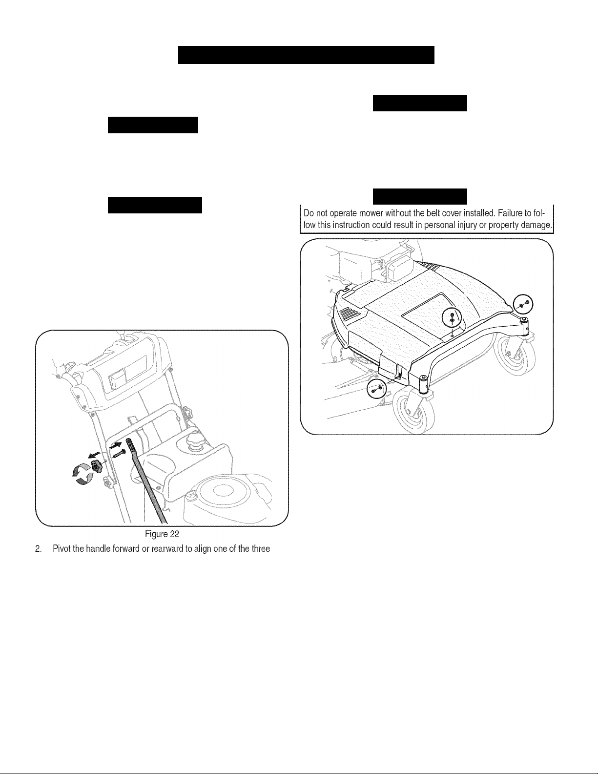
1. Remove the upper star knob and carriage screw on the right side
of the handle and the left side of the handle.
See Figure 22.
AWARNING
which secure it to the frame. See Figure 23.
AWARNING
holes on each support bar with the holes on the handle.
3. Reinstall the upper star knob and carriage screw on the right side
of the handle and the left side of the handle when a comfortable
height is achieved.
Figure 23
Place the deck height lever in its highest position.
Position wood blocks at various places under the deck's edge.
These will temporarily support the deck in the process of removing it.
Use the deck height lever to lower the deck, so that it rests on the
wood blocks.
20
Page 21
I
SERVICE AND MAINTENANC
J
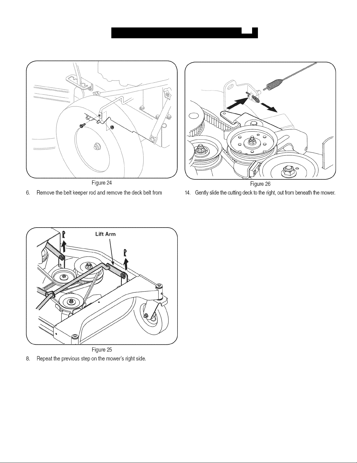
Remove the screw and flange nut which secures the belt keeper
rod to the left side of the mower’s frame. See Figure 24.
around the mower’s engine pulley.
Looking at the cutting deck from the left side, locate and carefully
remove the hairpin clips that secure the deck supports on the rear
left side and front left side of the deck. See Figure 25.
13. Pull the click pin out and unhook the drive spring cable from the
idler arm assembly. See Figure 26.
To install the cutting deck, follow the above steps in the opposite order
and manner of removal.
9. Carefully remove the front deck supports from the deck lift arms.
Figure 25.
10. Carefully unhook the mower’s lift assembly from the rear deck
supports.
11. Use the deck height lever to raise the lift assembly to its highest
position.
12. Remove the wooden blocks from under the deck and gently slide
the cutting deck toward the rear of the machine.
21
Page 22
SERVICE AND MAINTENANCE
J
CUTTING BLADES
4. To properly sharpen the cutting blades, remove equal amounts
AWARNING
Shut the engine off and remove ignition key before removing the
cutting blade(s) for sharpening or replacement. Protect your hands by
using heavy gloves when grasping the blade.
AWARNING
Periodically inspect the blade and/or spindle for cracks or damage,
especially after you've struck a foreign object. Do not operate the
machine until damaged components are replaced.
To remove the blades, proceed as follows.
1. Remove the deck from beneath the mower, (refer to Cutting Deck
Removal earlier In this section) then gently flip the deck over to
expose Its underside.
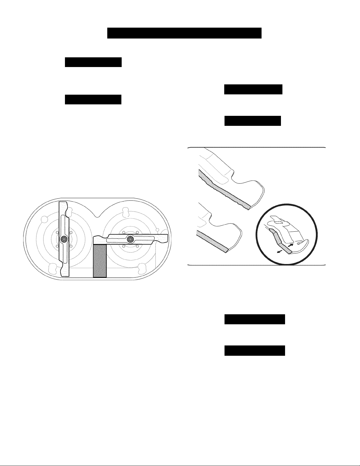
2. Place a block of wood between the center deck housing baffle
and the cutting blade to act as a stabilizer. See Figure 27.
If the cutting edge of the blade has previously been sharpened, or It
any metal separation Is present, replace the blades with new ones.
A poorly balanced blade will cause excessive vibration, may damage
to the mower and/or result In personal Injury.
of metal from both ends of the blades along the cutting edges,
parallel to the trailing edge, at a 25“- to 30“ angle. Always grind
each cutting blade edge equally to maintain proper blade balance.
See Figure 28.
A
CAUTION
AWARNING
5. Test the blade's balance using a blade balancer. Grind metal from
NOTE: When replacing the blade, be sure to install the blade with the
Figure 27
3. Remove the hex flange nut that secures the blade to the spindle
assembly. See Figure 27.
side of the blade marked “Bottom” (or with a part number stamped In
It) facing the ground when the mower Is In the operating position.
Figure 28
the heavy end until the blade balances evenly.
A
CAUTION
Use a torque wrench to tighten the blade spindle hex flange nut to
between 70 Ibs-ft and 90 Ibs-ft.
A
CAUTION
The cutting blades
the blades cannot be installed perpendicular to each other, the blade
timing belt must be reset. See your Sears or other qualified service
dealer to have the deck timing belt reset.
must
be Installed perpendicular to each other. If
22
Page 23
SERVICE AND MAINTENANC
J
TRAIL SHIELD
Jump Starting
AWARNING
Never operate the mower without the trail shield in place and working.
Failure to do so can result in personal injury.
To replace the trail shield, proceed as follows:
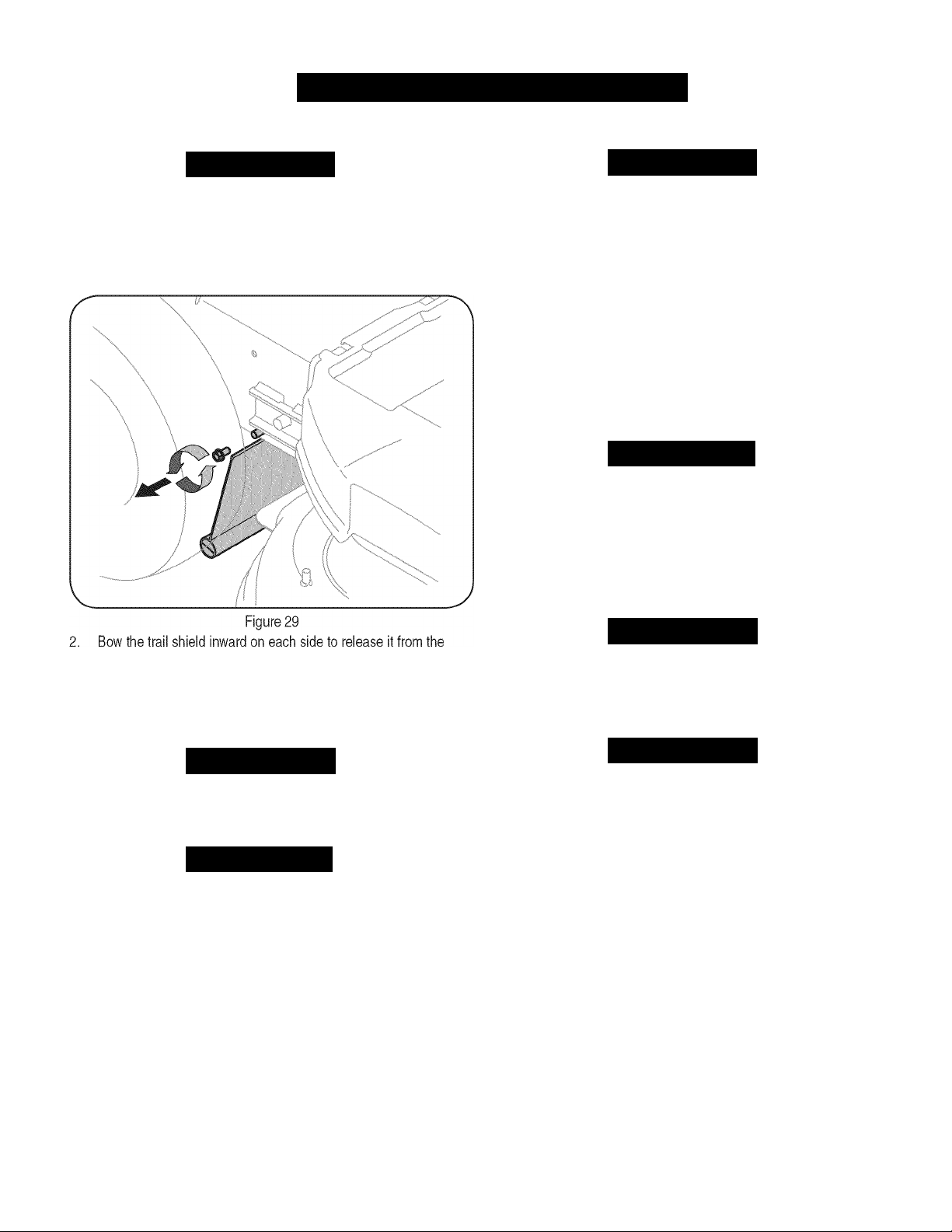
1. Remove the screw which secures the trail shield to the right side
of the mower. See Figure 29.
Never jump start a damaged or frozen battery. Be certain the vehicles
do not touch, and ignitions are off. Do not allow cable clamps to
touch.
1. Connect positive (+) cable to positive post (+) of your mower’s
2. Connect the other end of the cable to the (positive +) post of the
3. Connect the second cable (negative -) to the other post of the
4. Make the final connection on the engine block of the mower, away
If the jumper battery is installed on a vehicle (i.e. car, truck), do NOT
start the vehicle’s engine when jump starting your mower.
5. Start the mower (as instructed in the Operation section of this
6. Remove the jumper cables in reverse order of connection.
AWARNING
discharged battery.
jumper battery.
jumper battery.
from the battery. Attach to an unpainted part to assure a good
connection.
A CAUTION
manual).
Charging
mower frame.
3.
Install the replacement trail shield by following the steps above in
the opposite order and manner of removal.
BATTERY
Batteries give off an explosive gas while charging. Charge the battery
in a well ventilated area and keep away from an open flame or pilot
light as on a water heater, space heater, furnace, clothes dryer or
other gas appliances.
AWARNING
Battery posts, terminals, and related accessories contain lead and
lead compounds, chemicals known to the State of California to cause
cancer and reproductive harm. Wash hands after handling.
A CAUTION
If removing the battery, disconnect the NEGATIVE (Black) wire
from it's terminal first, followed by the POSITIVE (Red) wire. When
re-installing the battery, always connect the POSITIVE (Red) wire its
terminal first, followed by the NEGATIVE (Black) wire.
When charging your mower’s battery, use only a charger designed for
12V lead-acid batteries. Read your battery charger’s Owner’s Manual
prior to charging your mower’s battery. Always follow its instructions
and heed its warnings.
If your mower has not been put into use for an extended period of time,
charge the battery as follows:
SET your battery charger to deliver a max of 10 amperes.
IF your battery charger is automatic, charge the battery until the
charger indicates that charging is complete. If the charger is not
automatic, charge for at least eight hours.
AWARNING
AWARNING
23
Page 24

SERVICE AND MAINTENANCE
CHANGING THE DECK ENGAGEMENT BELT CHANGING THE DECK TIMING BELT
AWARNING
Shut the engine off and remove ignition key before removing the
cutting blade(s) for sharpening or replacement. Protect your hands by
using heavy gloves when grasping blades and pulleys.
AWARNING
The V-belts found on your mower are specially designed to engage and
disengage safely. A substitute (non-OEM) V-belt can be dangerous by
not disengaging completely. For a proper working machine, use identi
cal replacement belts as listed In parts list of this operator’s manual.
All belts on your mower are subject to wear and should be replaced if
any signs of wear are present. To change or replace the deck engage
ment belt on your mower, proceed as follows:
1. Remove the cutting deck from the mower as instructed earlier in
this section.
AWARNING
Avoid pinching injuries. Never place your fingers on the Idler spring or
between the belt and a pulley while removing the belt
2. Remove the belt cover as Instructed earlier In this section. Refer
to Figure 20 on page 19.
3. Remove the belt keeper as Instructed earlier In this section. Refer
to Figure 21 on page 19.
4. Loosen, but not remove, the nut and bolt which secures each
deck Idler pulley. See Figure 30.
Several components must be removed and special tools used In
order to change the mower deck's timing belt. See your Sears or
other qualified service dealer to have the deck timing belt replaced.
CHANGING THE TRANSMISSION DRIVE BELT
Several components must be removed and special tools used in order
to change the mower's transmission drive belt. See your Sears or other
qualified service dealer to have the transmission drive belt replaced.
FUSE
AWARNING
Before servicing, repairing, or inspecting, always disengage blades,
stop engine and remove key to prevent unintended starting.
A 20 Amp fuse is installed In your mower's wiring harness to protect
the mower’s electrical system from damage caused by excessive
amperage.
If the electrical system does not function, or your mower's engine will
not crank, first check to be certain that the fuse has not blown. It Is
located near the battery.
A CAUTION
Always use a replacement fuse with the same amperage capacity as
the blown fuse.
Figure 30
5. Remove the belt from around all pulleys.
6. Route the new belt as Illustrated In Figure 30.
7. Retighten the nuts and bolts which secure each Idler pulley.
8. Reattach the belt keeper and belt cover.
24
Page 25

SERVICE AND MAINTENANC
MAINTENANCE SCHEDULE
J
Interval
Each Use 1. Mower blades 1. As required
2. Loose or missing hardware 2. Tighten or replace
3. Belts 3. Check
4. Engine oil level 4. Check
5. Controls 5. Check for proper operation
6. Mulch plug (if fitted) 6. Check for proper plug installation
1st 2 hours 1. Engine oil 1. Change
25 hours 1. Engine oil 1. Change
2. Air cleaner 2. Clean or replace
3. Mower blades
4. Control linkages and pivots 4. Lube with light oil
50 hours 1. Front Wheel Bearings 1. Grease
Annually or 100 hours 1. Spark plug 1. Clean, replace, re-gap
2. Rear Wheels 2. Grease
Before Storage 1. Fuel system 1. Run engine until it stops from lack of
Item
Service Service Log
3. Sharpen and balance
fuel or add a gasoline additive to the
gas in the tank.
25
Page 26

OFF-SEASON STORAG
Awarning
Never store lawn mower with fuel
ventilated areas where fuel fumes may reach an open flame, spark,
or pilot light as on a furnace, water heater, clothes dryer, or gas
appliance.
in
tank indoors or in poorly
I
PREPARING THE ENGINE
For engines stored over 30 days:
1. To prevent gum from forming in fuel system or on carburetor
parts, run engine until it stops from lack of fuel or add a gasoline
additive to the gas in the tank. If you use a gas additive, run the
engine for several minutes to circulate the additive through the
carburetor—after which the engine and fuel can be stored up to
six months.
2. While engine is still warm, change the oil.
3. Remove spark plug and pour approximately 1 oz. (30 ml) of clean
engine oil into the cylinder. Pull the recoil starter several times to
distribute the oil, and reinstall the spark plug.
4. Clean engine of surface debris.
PREPARING THE LAWN MOWER
• When storing the mower in an unventilated or metal storage shed,
care should be taken to rustproof the non-painted surfaces. Using
a light oil or silicone, coat the equipment, especially any springs,
bearings, and cables.
• Remove all dirt from exterior of engine and equipment.
• Follow lubrication recommendations.
• Store equipment in a clean, dry area. Do not store in an area
where equipment is present that may use a pilot light or has a
component that can create a spark.
ACCESSORIES AND ATTACHMENTS
The following attachments and accessories are available for the lawn mower. Contact a Sears Service Center 1-800-4-MY-HOME® for more
information.
PART NO. DESCRIPTION
33731 Bagger Grass Collector
26
Page 27

P
TROUBLESHOOTIN
Æ
J
Awarning
Before performing any type of maintenance/service, disengage all
controls and stop the engine. Wait until all
a complete stop. Disconnect
engine to prevent unintended starting. Always wear safety glasses during
operation or while performing any adjustments or repairs.
This section addresses minor service issues. To locate the nearest Sears Service Center or to schedule service, simply contact Sears
at 1-800-4-MY-HOME®.
spark
moving
plug wire and ground it against the
parts have come to
Problem
Engine fails to start 1. Choke not activated
2. Throttle/choke control not in correct position
3. Spark plug wire disconnected
4. Faulty spark plug
5. Fuel tank empty or stale fuel
6. Blocked fuel line
Engine runs erratically 1. Unit running with choke applied
2. Spark plug wire loose
3. Stale fuel
4. Water or dirt in fuel system
5. Dirty air cleaner
Engine overheats 1. Engine oil level low
2. Airflow restricted
Engine hesitates at high RPMs 1. Spark plug gap set too close 1. Remove spark plug and adjust gap.
Engine idles poorly 1. Fouled spark plug
2. Dirty air cleaner
Excessive vibration 1. Cutting blades loose or unbalanced
2. Damaged, dull, or bent cutting blade
3. Loose hardware
Unit fails to propel itself 1. Drive belt loose or damaged 1. Replace drive belt.
Poor mowing performance 1. Dull blade(s)
2. Broken, loose, or worn belt(s)
3. Blade(s) out of balance
Cause Remedy
1. Place throttle/choke control lever into choke position.
2. Place throttle/choke lever into fast position.
3. Connect wires to spark plug.
4. Clean, adjust gap, or replace.
5. Fill tank with clean, fresh gasoline.
6. Have fuel line cleaned by a Sears service dealer.
1. Move throttle/choke lever out of choke position.
2. Connect and tighten spark plug wire.
3. Fill tank with fresh gasoline.
4. Drain fuel. Refill with fresh fuel.
5. Replace air cleaner cartridge.
1. Fill engine with proper amount and type of oil.
2. Clean grass clippings and debris from around the
engine’s cooling fins and blower housing.
1. Replace spark plug and adjust gap.
2. Replace air cleaner cartridge.
1. Tighten blade and spindle. Balance blade.
2. Replace blade.
3. Tighten all nuts and bolts.
1. Sharpen or replace blade(s).
2. Replace belt(s).
3. Balance or replace blade(s).
MED MOIE HELP?
Youll find the answer and more on iiiaiia§eii
- Find this and alt your other product manuals online.
Get answers from our team of home experts.
Get a personalized maintenance plan for your home.
■ Find information and tools to help with home projects.
nmt ■ ..I
brought to you by Sears
27
Page 28

PARTS LIS
33-inch Wide Cut Mower — Model No. 247.889980
I
28
Page 29

PARTS LIS
33-inch Wide Cut Mower — Model No. 247.889980
I
J
Ref. No. Part No. Description
1 687-02427 Lever Assembly: LH
2 687-02426 Lever Assembly: RH
3 710-0572 Screw, Carriage: 5/16-18 x 2.25
4 710-0599 Screw, 1/4-20x0.500
5 710-0606 Screw, Cap: 1/4-20 x 1.50
6 712-04063 Nut, Flange Lock: 5/16-18
7 912-0442 Nut, Lock Cap: 1/4-20
8 720-0274 Grip, 1.0IDx5.0Lg
9 720-04072A Star Knob 5/16-18
10 736-0270 Washer, Bell: .265 x .75 x .062
11 938-0140 Screw, Shoulder, .435 x .178-5/16
12 938-1226 Screw, Shoulder, .375 x 1.355: 1/4-20
13 946-04609 Cable, Clutch Wheel
14 946-04606 Cable, Brake, Transmission: RH
15 946-04610 Cable, Clutch Deck
16 946-04604 Cable, Throttle/Choke: 38 x 1.1
17 946-04608 Cable, Brake, Transmission: LH
18 749-04330-0637 Lower Handle
19 749-04331-0637 Upper Handle: LH
20 749-04332-0637 Upper Handle: RH
21 749-04333-0637 Brace Tube
22 787-01548-4028 Handle Panel
23 787-01490A-0637 Cable Mount Bracket: RH
787-01491A-0637 Cable Mount Bracket: LH
24 687-02255B-4028 Frame Assembly
25 687-02263-0637 Caster Wheel Bracket Assembly
26 687-02419-0637 Deck Lift Assembly: RR
27 687-02265-0637 Deck Lift Assembly: Front
28 710-0627 Screw, HH Cap: 5/16-24 x .750
29 925-1649 Lamp Socket
30 710-04312 Screw, HH Cap: 5/16-18 X.50
31 712-04065 Nut, Flange Lock: 3/8-16
32 914-0145 Click Pin: .092 X 1.64
33 720-0311 Handle Grip 1/2
34 931-05684 Belt Cover 33 Wide Cut Mower
35 731-05791 Snap Spacer: .63 ID x .75 LG
36 732-04418A Deck Height Lever
37 736-0242 Washer, Bell: .340 x .872 x .060
38 736-0343 Washer, Flat: .330 x 1.25 x .120
39 936-0351 Washer, Flat: .760 ID x 1.50 OD
40 937-3000 Lube Fitting: 3/16: LNC#70
Ref. No. Part No. Description
41 738-04216A Bolt, Shoulder: .625 x 2.515 x 3/8-16
42 741-0660A Flange Bearing: .760 x .941 x 1.0
43 787-01496-4028 Height Adjustment Bracket
44 787-01510-0637 Link Pivot Bracket
45 787-01521-0637 Lever Pivot Bracket
46 710-0604A Screw, TT: 5/16-18 x .625
47 738-04282 Screw, Shoulder: .32 x 1.8 x 1/4-20
48 951-10541 Fuel Tank, 2 Gal.
49 951-10514 Fuel Cap
50 787-01507-4028 Fuel Tank Mounting Bracket
51 734-04243 Wheel, 8x1.75
*
52 710-1315 Screw, TT: 3/8-16x1.25
53 710-0136 Screw, HH Cap: 1/4-20x1.75
54 712-3006 Nut, Hex: 1/4-20
55 631-04339P Handle Panel
56 931-06935 Tank Cover
57 725-0157 Cable Tie
58 710-0642 Screw, TT: 1/4-20 x .75
59 710-04666 Screw, 1/4-20 x .75
60 712-0271 Nut, Sems: 1/4-20
61 712-04064 Nut, Flange Lock: 1/4-20
62 936-0463 Washer, Flat: .25 x .63 x .0515
63 925-04022B Hour Indicator Meter
64 925-1741 Key Switch
65 725-04439 Solenoid, 12V
66 925-1707D Battery
67 731-05319 Lons
68 751B221535 Casing Clamp
69 747-04657 Battery Hold Down
70 751-10349 Fuel Hose
71 726-0205 Hose Clamp
72 951-10517A Oil Drain
73 751-3141-14 Oil Drain Hose
74 710-1237 Screw, 10-32 X .625
75 925-1745A Key, Ignition, Black
76 710-0896 Screw, 1/4-20 X 1.75
77 925-04213 Lamp
78 777X41805 Label Reflector
*
*
Not pictured
941-0706 Flange Bearing, Wheel
725-04478 Starter Wire
925-04911 Wiring Harness
29
Page 30

PARTS LIS
33-inch Wide Cut Mower — Model No. 247.889980
11
I
20 /10
30
Page 31

PARTS LIS
33-inch Wide Cut Mower — Model No. 247.889980
I
J
Ref. No. Part No. Description
1 17840-0637 Transaxle Bracket Mount
2 918-04639 Transmission 4-Speed
3 710-0176 Screw, HH Cap: 5/16-18x2.75”
4 710-0376 Screw, HH Cap: 5/16-18x1.00”
5 710-04377 Screw, HH Cap: 7/16-20x2.75”
6 710-0513 Screw, HH Cap: 1/4-28 x.625”
7 710-0520 Screw, HH Cap: 3/8-16x1.50”
8 710-0347 Screw, HH Cap: 3/8-16x1.75”
9 710-3008 Screw, HH Cap: 5/16-18 x .75”
10 710-3015 Screw, HH Cap: 1/4-20 x.75”
11 911-1000 Belt Keeper
12 712-04063 Nut, Flange Lock: 5/16-18
13 712-04064 Nut, Flange Lock: 1/4-20
14 712-04065 Nut, Flange Lock: 3/8-16
15 712-0700 Nut, Flange: 9/16-18
16 914-0145 Hairpin Clip: 092” x 1.64” Long
17 718-04407 Pulley Hub
18 720-0142 Grip
19 731-05766 Trailing Shield
20 732-04409 Extension Spring
21 732-04443A Extension Spring
22 736-0105 Washer, Spring: .401” x .870” x .063”
23 736-0322 Washer, Flat: 450” x 1.250” x .164”
24 736-0270 Washer, Bell
25 736-04256 Washer, Flat: .39” x .87” x .06”
26 738-04166 Spacer, Shoulder: .50” x .1475”
27 747-04635A Belt Keeper Rod
28 747-04673 Loop Link Coupling
29 747-04678A Trans Mount Rod
30 954-04145A Belt, V Type
31 756-04129B Idler Pulley: 4.25” Dia.
32 756-04258 Flat Sheave 7.75”
33 756-04260 Engine Pulley 3.20” x 4.35” Dia.
34 756-04280 Idler Pulley 3.50” Dia.
35 787-01469B-0637 Shift Rod, Lower
36 787-01470A-0637 Shift Rod, Upper
37 787-01473-0637 Belt Keeper
38 787-01523A Wheel Drive idler Bracket
39 918-04438B Drive Spindle Assembly
Ref. No. Part No. Description
40 918-04439B Spacer Spindle Assembly
41 631-04252 Mulch Plug
42 987-02420 Idler Arm Assembly
43 687-02476-0691 Deck Assembly 33-inch
44 710-0451 Bolt, Carriage: 5/16-18 x .75”
45 710-0514 Screw, HH Cap: 3/8-16x1.00”
46 710-0560 Screw, Carriage: 3/8-16 x 1.75”
47 710-04484 Screw, LD: 5/16-18 X.750”
48 710-3184A Screw, HH Cap: 3/8-16 x 2.00”
49 931-04244 Chute Deflector Assy (includes ref. 72-76)
50 712-0417A Nut, Flange: 5/8-18
51 912-0641 Nut, Hex
52 912-3017 Nut, Hex 3/8-16
53 732-04406 Extension Spring: Timing Belt Tension
54 732-04452 Extension Spring: Deck Brake
55 736-0225 Washer, Lock
56 938-0347 Spacer, Shoulder: .625” x .169”
57 738-04162A Spacer, Shoulder: .884” x .190”
58 942-04154A Blade: 17.9”
59 754-04136 Belt, Timing
60 954-04139 Belt, V Type
61 756-04129В Idler Pulley 4.25”
62 756-04280 Idler Pulley 3.50”
63 756-0616 Idler Pulley V-Type 5.0”
64 787-01440-0637 Idler Timing Bracket
65 921-04041 Water Nozzle Adapter
66 737-04003D Water Nozzle
67 634-04285-0911 Wheel 16x4 x8
68 736-0242 Washer, Bell: .340” x .872” x .060”
69 710-0627 Screw, HH Cap: 5/16-24 x .75”
70 710-1315 Screw, TT: 3/8-16 x 1.25”
71 710-04187 Screw, HL: 1/4-15 x.50”
72 711-04027 Deflector Pin
73 787-01017A-0637 Deflector Hinge Bracket
74 732-04012 Deflector Torsion Spring
75 726-04009 Push Cap
76
—
977S30145 Label Chute Deflector (not shown)
Chute Deflector, 33” SD Deck
31
Page 32

PARTS LIS
33-inch Wide Cut Mower — Model No. 247.887330
I
/%
35A /
29B
MODEL and SERIAL
NUMBERS HERE
32
Page 33

PARTS LIS
33-inch Wide Cut Mower — Model No. 247.887330
I
J
Ref. No. Part No. Description
1 TC-772147 Transaxle Cover
2 TC-780086A Needle Bearing (V ” long)
3 TC-770128A Transaxle Case
4 TC-776395 Countershaft
5 TC-776409 Output Shaft
6 TC-778364 Spur Gear (38T-PM/SER)
6A TC-778369 Spur Gear (15T-PM/SER)
7 TC-778330 Spur Gear (11T-PM/SER)
8 TC-792180A Shift Key Set (Qty. 2)
9 TC-784352 Shift Collar
10 TC-784378 Shift Rod & Fork Assembly
11
12 TC-778309 Input Bevel Pinion (13T-PM)
13 TC-778368 Bevel Gear 13T (Inch ref. 13 & 14)
14 TC-778368 Bevel Gear 13T (Inch ref. 13 & 14)
15 TC-778370 Ring Gear (43T)
17 TC-786188 Drive Pin
18 TC-786102 Spacer (1.130” X.695”)
20 TC-792077A Ball (Stainless Steel 5/16” dia.)
21 TC-792211 Screw, 3/8-16x3/8”
22 TC-792079 Spring
25 TC-792073A Screw, 1/4-20 X 1-1/4”
25A TC-792177 Screw, 1/4-20 X 1-3/8”
26 TC-792125 Retaining Ring-package of 2
27 TC-792035 Retaining Ring
28 TC-788040 Retaining Ring
29 TC-780072 Washer .627” ID .031”
29A TC-780160 Thrust Washer (.563” ID x .031”)
29B TC-780051 Thrust Washer (.762” ID X .031”)
30 TC-780108 Shift Washer (Cupped)
31 TC-780001 Washer .750” ID .56”
31A TC-780195 Washer .750” ID .062
32 TC-788083 Oil Seal 5/8”
32A TC-792001 0 Ring (.823” OD)
34 TC-780194 Bushing (.563”)
35 TC-780193 Flanged Bushing (.625” ID)
35A TC-780197 Flanged Bushing (.751” ID)
TC-778334 Bevel Gear (30T-PM)
Ref. No. Part No. Description
36 TC-790075 Brake Disk
37 TC-790007 Brake Pad Plate
38 TC-799021A Brake Pad (pkg. of 2)
39 TC-786026 Dowel Pin .3125” x .750”
40 736-3078 Washer .312” ID .059”
41 TC-790104 Brake Lever
42 TC-792177 Screw 1/4-20x1-3/8”
43 912-0237 Lock Nut 5/16-24
44 TC-790025 Brake Pad Holder
46 TC-786086 Bracket
47 TC-775146 Axle (10.719” long) (Incl. 26)
48 TC-775147 Axle (15.312” long) (Incl. 26)
49 TC-778338 Spur Gear (27T-PM/IC)
50 TC-778342 Spur Gear (22T-PM/IC)
51 TC-778313 Spur Gear (19T-PM/IC)
52 TC-778350 Spur Gear (16T-PM/IC)
56 TC-778337 Spur Gear (13T-PM/SER)
57 TC-778341 Spur Gear (18T-PM/SER)
58 TC-778351 Spur Gear (21T-PM/SER)
59 TC-778349 Spur Gear (24T-PM/SER)
63 TC-786071 Countershaft Spacer 1-1/8” x 3/8”
64 TC-786072 Brake Shaft Spacer 1-3/8” x 3/8”
65 TC-780189 Washer .563” ID .062
66 TC-776472 Input Shaft
67 TC-776396 Brake Shaft
69 TC-792170 Retaining Ring (.75” x .042”)
70 TC-786187 Spacer (.890”)
71B TC-788092 0-Ring
76 TC-780090 Flat Washer (1.128” ID x .058”)
77 TC-788078A Retaining Ring (1.125” x .050”)
79 TC-792144 Spring
82 TC-778333 Bevel (30T) & Spur Gear
83 TC-778338 Spur Gear (27T-PM/IC)
85 TC-792154 Oil Fill Plug
87 TC-788089A Oil Seal 9/16” ID
157 TC-788088A Oil Seal 3/4” ID
Page 34

Briggs and Stratton 219707-0712-B1
337
PARTS LIS
883
238 3
I
33
42
«)
«
40
35
34
868
42
10%
635 4-
850
1029 s~v
192
1034
830 ^
13
1022
1026
870
45 /^2)
ÖPI
|'li4
51AÍ ‘
51
“si A# 617 0/5^
617
36
i/'
.....................
^
...-...
654,
53.
51 UA
-^-4
54 «te
34
Page 35

Briggs and Stratton 219707-0712-B1
I
PARTS LIS
J
125
131
130
95 © '■
117
(T)|
987 ©
'a'Q
133
975
141
k ©-A«©9
'V
137
til
104 7©^
........
©
108 PI)
¡cry
127
98
&
135
137
634 217jCi
633 it-i
94
1091
187
431
1266
37
V J
1266A
78
!■'
,:1'
601
240
00
J
1040
1127
118
Si>
121 CARBURETOR OVERHAUL KIT
51 f
51A
V -127 0
95 217 Ü
104
105
617 r-
633 gj,
987©
1266 '
1266A C“")
305A
305
1036 EMISSIONS LABEL
304
1397
1267
---JV
773
|l 1
601
601^;
643 IV© VC
n
967
445
itnäij
968
.
©'
f\
187
187A
[
35
Page 36

Briggs and Stratton 219707-0712-B1
PARTS LIS
I
222
188
265 '
267
621
507
520
209 \m 216
if /
0l
359
373
521
#
324
415
1054
864
883 fe--
'\t>
823
'¿J-
/'
1'.' SJ i|
1044
|t r It ' •
1005 i' 'll
• f <
23
36
Page 37

Briggs and Stratton 219707-0712-B1
334
333
I
PARTS LIS
J
356
635
'^1
729
697^
37
1119 S
Page 38

Briggs and Stratton 219707-0712-B1
11
684 '
584 ill
1264
1263
850
PARTS LIST
306
38
Page 39

Briggs and Stratton 219707-0712-B1
I
PARTS LIS
J
Ref. No. Part No. Description
1 699045 Cyiinder Assembiy
2 399265 Kit-Bushing/Seal (Magneto Side)
3 391086s Seal-Oii (Magneto Side)
4 697106 Sump-Engine
5 792964 Head-Cyiinder
7 273280s Gasket-Cyiinder Head
9 697109 Gasket-Breather
(Breather Gasket and Liquid Seaiant are
interchangeabie, Reference 850)
10 697157 Screw (Breather Assembiy)
11 794683 Tube-Breather
12 697110 Gasket-Crankcase
13 690360 Screw (Cyiinder Head)
15 690946 Plug-Oii Drain
16 796146 Crankshaft
20 795387 Seal-Oii (PTO Side)
22 692125 Screw (Crankcase Cover/Sump)
23 698281 Flywheel
24 222698s Key-Flywheel
25 796155 Piston Assembly (Standard)
794891 Piston Assembly (.020” Oversize)
26 792306 Ring Set (Standard)
792643 Ring Set (.020” Oversize)
27 698469 Lock-Piston Pin
28 697099 Pin-Piston
29 791633 Rod-Connecting
32 791118 Screw (Connecting Rod)
33 791934 Valve-Exhaust
34 791935 Valve-Intake
35 691279 Spring-Valve (Intake)
36 691279 Spring-Valve (Exhaust)
37 697352 Guard-Flywheel
40 690964 Retainer-Valve
42 499586 Keeper-Valve
43 691968 Slinger-Governor/Oil
45 690564 Tappet-Valve
46 793880 Camshaft
48 697740 Short Block
50 697361 Manifold-Intake
51 692137 Gasket-Intake
Ref. No. Part No. Description
51A 794312 Gasket-Intake
53 690227 Stud (Carburetor)
54 691148 Screw (Intake Manifold)
78 691003 Screw (Flywheel Guard)
81 691178 Lock-Muffler Screw
94 793610 Kit-Idle Mixture
95 690718 Screw (Throttle Valve)
98 695408 Kit-Idle Speed
104 694918 Pin-Float Hinge
105 696136 Valve-Float Needle
108 698773 Valve-Choke
117 796079 Jet-Main (Standard)
118 796332 Jet-Main (High Altitude)
121 698787 Kit-Carburetor Overhaul
125 794653 Carburetor
127 690727 Plug-Welch
130 698774 Valve-Throttle
131 698776 Kit-Throttle Shaft
133 694914 Float-Carburetor
135 698780 Tube-Fuel Transfer
137 698781 Gasket-Float Bowl
141 698778 Kit-Choke Shaft
146 691639 Key-Timing
177 691031 Seal-0 Ring (Dipstick)
187 791805 Line-Fuel (Formed)
187A 791744 Line-Fuel (Formed)
188 691693 Screw (Control Bracket)
192 691986 Adjuster-Rocker Arm
202 691841 Link-Mechanical Governor
209 792813 Spring-Governor (Brown)
216 691840 Link-Governor
217 695409 Spring-Choke Return
222 694042 Bracket-Control
227 691374 Lever-Governor Control
232 691842 Spring-Governor Link
238 691843 Cap-Valve
240 394358s Filter-Fuel
265 691024 Clamp-Casing
267 794904 Screw (Casing Clamp)
300 796000 Muffler
39
Page 40

Briggs and Stratton 219707-0712-B1
PARTS LIS
Ref. No. Part No. Description
304 BS-796414 Housing-Blower (Red)
305 BS-697102 Screw (Blower Housing) (Long)
305A BS-793376 Screw (Blower Housing) (Short)
306 BS-697359 Shield-Cylinder
307 BS-691003 Screw (Cylinder Shield)
309 BS-693551 Motor-Starter
310 BS-690323 Bolt (Starter Motor)
311 BS-497608 Brush Set
324 BS-796308 Screen/Cup Assembly
333 BS-795315 Armature-Magneto
334 BS-691061 Screw (Magneto Armature)
337 BS-491055S Plug-Spark
356 BS-398808 Wire-Stop
358 BS-697151 Gasket Set-Engine
359 BS-691077 Washer (Ground Terminal)
373 BS-691612 Nut (Ground Terminal)
404 BS-691691 Washer (Governor Crank)
415 BS-794129 Plug (Rotating Screen)
431 BS-697122 El bow-Intake
445 BS-698413 Filter-Air Cleaner Cartridge
474 BS-696459 Alternator
505 BS-691251 Nut (Governor Control Lever)
507 BS-691972 Insulator
510 BS-693699 Drive-Starter
513 BS-692024 Clutch-Drive
520 BS-691084 Terminal-Ground
521 BS-690581 Shield-Cable
523 BS-699908 Dipstick
524 BS-691032 Seal-Dipstick Tube
525 BS-697184 Tube-Dipstick
544 BS-692034 Armature-Starter
552 BS-697144 Bushing-Governor Crank
562 BS-691119 Bolt (Governor Control Lever)
579 BS-691029 Nut (Starter Cable)
584 BS-794682 Cover-Breather Passage
601 BS-791850 Hose-Clamp
613 BS-691416 Screw (Muffler) (Long)
613A BS-691678 Screw (Muffler) (Short)
614 BS-691620 Pin-Cotter (Governor Crank)
616 BS-692012 Crank-Governor
Ref. No. Part No. Description
617 BS-692138 Seal-0 Ring (Intake Manifold)
621 BS-692310 Switch-Stop
633 BS-699813 Seal-Choke/Throttle Shaft (Choke Shaft)
634 BS-698779 Spring/Seal Assembly
635 BS-691909 Boot-Spark Plug
643 BS-697155 Retainer-Air Filter
654 BS-690958 Nut (Carburetor)
691 BS-692407 Seal-Governor Shaft
697 BS-690372 Screw (Drive Cap)
718 BS-690959 Pin-Locating
729 BS-691224 Clip-Wire
741 BS-697128 Gear-Timing
773 BS-796448 Retainer
783 BS-693713 Gear-Pinion
797 BS-693167 Nut (Brush Retainer)
801 BS-691283 Cap-Drive
802 BS-691286 Cap-End
803 Housing-Starter
(Not Serviced Separately, Order Starter
Motor 693551, Reference 309)
823 BS-698941 Screw (Muffler Adapter)
830 BS-691095 Stud-Rocker Arm
847 BS-790442 Dipstick/Tube Assembly
850 BS-100106 Sealant-Liquid
(Interchangeable with Rocker Cover
Gasket and Breather Gasket)
851 BS-692424 Terminal-Spark Plug
864 BS-796002 Adapter-Muffler
868 BS-690968 Seal-Valve
883 BS-692236 Gasket-Exhaust
914 BS-691108 Screw (Rocker Cover)
967 BS-697292 Filter-Pre Cleaner
968 BS-697420 Cover-Air Cleaner (Black)
BS-697422 Cover-Air Cleaner (Red)
975 BS-698783 Bowl-Float
987 BS-698777 Seal-Throttle Shaft
1005 BS-796082 Fan-Flywheel
1022 BS-272475S Gasket-Rocker Cover
(Rocker Cover Gasket and Liquid Sealant
are interchangeable, see Reference 850)
40
Page 41

PARTS LIS
Briggs and Stratton 219707-0712-B1
Ref. No. Part No. Description
1023 BS-794659 Cover-Rocker
1026 BS-794573 Rod-Push (Exhaust)
BS-697394 Rod-Push (Intake)
1029 BS-691751 Arm-Rocker
1034 BS-690822 Guide-Push Rod
1036 Label-Emissions (Available from a Briggs &
Stratton Authorized Dealer)
1040 BS-698368 Plate-Trim
1044 BS-698139 Screw (Flywheel)
1051 BS-691265 Ring-Retaining
1054 BS-280275 Tie-Cable
1059 BS-698516 Kit-Screw/Washer (Alternator)
1090 BS-691293 Retainer-Brush
1091 BS-691333 Cap-Limiter
1095 BS-795807 Gasket Set-Valve
1119 BS-691183 Screw (Alternator)
1127 BS-695407 Screw (Float Bowl)
1263 BS-697124 Reed-Breather
1264 BS-697104 Screw (Breather Reed)
1266 BS-691917 Seal-0 Ring (Intake Elbow) (Red)
1266A BS-697123 Seal-0 Ring (Intake Elbow) (Large)
1267 BS-697419 Latch-Blower
BS-697424 Latch-Blower Housing (Red)
1329 BS-2197070026G1 Replacement Engine
Housing
(Black)
I
J
41
Page 42

777S30145
DO NOT OPERATE UNLESS AN UNDAMAGED DISCHARGE
COVER OR ENTIRE GRASS CATCHER IS IN PLACE.
KEEP HANDS and FEET AWAY
777D09788 777I22793
OIL DRAIN VALVE
DECK
[IZME
SYSTEM"
Patent Pending
See Operator’s Manual
»VOID
SERIOUS INJURY OR DEWH
■ abjaROUND children OB OTHERS
* sfniS?K “™H slopes, do not mo«
»iSS'’“TERTHAN15-.M0WACR0SSjHffi
UP «0 DOWN. LOOK DOWN AND BfflIND BEFOffi
fflO WHILE MOVING BACKWARDS.
ErS' DEVICES (BLADE <-n>lTO°L.^-^..“pn\AT^
"" ™i!TCJW PLACE AND WORKING. IF n...ARED.RSPL_A^ iW
777122759
777122760
HEIGHT ADJUSTER
777I22808
777D13372
• ELECT.RIC: 5TAÌÌT
* CLtlAK VIEW LIGKÌ ÌNG SYSTfcM
m Hni !H MFTf R ft SiGH'i f',Ai iriR R[ If-I T.ANK
777I22815
STABTING il4STRyCTiONS:
1. Read Operator’s Manual Before Operating Machine.
2. Move Shift Uver to Neutral" N * Position.
3. Move Thrnttle/Choke Cnnfrol Lever tn Choke |X| Position.
4. Insert Key, Turn to Start 0) Position, Release Key to Run Position.
5. Move Throttle / Choke Control Lever to Fast Rabhit ^ Position.
777122809
m
___________
6^
1 .Insert Mulch Plug's front tan inio sloi on
i 2. Pivot Mulch Plug inboard into discharge opening.
! 3- Slide rearward until slot bottoms out against edge of discharge opening.
; 4. Lower Discharge Chute to lock Mulch Plug in place.
^ ............. ^
^ 0
..............................
juiside o< or-ck
42
777122814
777X43688
DOiOT
'USE E85 OiFUEL'
COiTAiiiie IMORE
|THAi10%ETHAi0L|
M
Turn Key
to Stop (§
Position.
BLADE
CONTROL
Page 43

REPAIR PROTECTION AGREEMENT
Congratulations on making a smart purchase. Your new Craftsman®
product is designed and manufactured for years of dependable opera
tion. But like all products, it may require repair from time to time. That's
when having a Repair Protection Agreement can save you money and
aggravation.
Here’s what the Repair Protection Agreement* includes:
• Expert service by our 10,000 professional repair specialists
Once you purchase the Agreement, a simple phone call is all that it
takes for you to schedule service. You can call anytime day or night, or
schedule a service appointment online.
The Repair Protection Agreement is a risk-free purchase. If you cancel
for any reason during the product warranty period, we will provide a full
refund. Or, a prorated refund anytime after the product warranty period
expires. Purchase your Repair Protection Agreement today!
• Unlimited service and no charge for parts and labor on all
covered repairs
• Product replacement up to $1500 it your covered product can’t be
fixed
Some limitations and exclusions apply. For prices and additional
information in the U.S.A. call 1-800-827-6655.
‘Coverage in Canada varies on some items. For full details call
Sears Canada at 1-800-361-6665.
• Discount of 10% from regular price of service and related installed
parts not covered by the agreement; also, 10% off regular price of
preventive maintenance check
• Fast help by phone - we call it Rapid Resolution - phone support
from a Sears representative. Think of us as a “talking owner’s
manual.”
Sears Installation Service
For Sears professional installation of home appliances, garage door
openers, water heaters, and other major home items, in the U.S.A. or
Canada call 1-800-4-MY-HOME®.
43
Page 44

FEDERAL and/or CALIFORNIA EMISSION CONTROL WARRANTY STATEMENT
YOUR WARRANTY RIGHTS AND OBLIGATIONS
MTD Consumer Group Inc, the United States Environmental Protection Agency (EPA), and, for those products certified for sale in the state of California, the
California Air Resources Board (CARB) are pleased to explain the emission (evaporative and/or exhaust) control system (ECS) warranty on your outdoor 2006
and later small off-road spark-ignited engine and equipment (outdoor equipment engine) In California, new outdoor equipment engines must be designed, built and
equipped to meet the State’s stringent anti-smog standards (in other states, 1997 and later model year equipment must be designed, built, and equipped to meet
the U.S. EPA small off-road, spark ignition engine regulations. MTD Consumer Group Inc must warrant the ECS on your outdoor equipment engine for the period of
time listed below provided there has been no abuse, neglect or improper maintenance of outdoor equipment engine.
Your ECS may include parts such as the carburetor, fuel-injection system, the ignition system, catalytic converter, fuel tanks, fuel lines, fuel caps, valves, canisters,
filters, vapor hoses, clamps, connectors, and other associated emission-related components.
Where a warrantable condition exists, MTD Consumer Group Inc will repair your outdoor equipment engine at no cost to you including diagnosis, parts and labor.
MANUFACTURER’S WARRANTY COVERAGE:
This emission control system is warranted for two years. If any emission-related part on your outdoor equipment engine is defective, the part will be repaired or
replaced by MTD CONSUMER GROUP INC.
OWNER’S WARRANTY RESPONSIBILITIES:
As the outdoor equipment engine owner, you are responsible for performance of the required maintenance listed in your owner’s manual. MTD Consumer Group
Inc recommends that you retain all receipts covering maintenance on your outdoor equipment engine, but MTD Consumer Group Inc cannot deny warranty solely
for the lack of receipts.
As the outdoor equipment engine owner, you should however be aware that MTD Consumer Group Inc may deny you warranty coverage if your outdoor equipment
engine or a part has failed due to abuse, neglect, or improper maintenance or unapproved modifications.
You are responsible for presenting your outdoor equipment engine to MTD Consumer Group Inc’s distribution center or service center as soon as the problem
exists. The warranty repairs should be completed in a reasonable amount of time, not to exceed 30 days. If you have a question regarding your warranty coverage,
you should contact the MTD Consumer Group Inc Service Department at 1-800-800-7310 or via email at
http://support.mtdproducts.com
GENERAL EMISSIONS WARRANTY COVERAGE:
MTD Consumer Group Inc warrants to the ultimate purchaser and each subsequent purchaser that the outdoor equipment engine is: Designed, built and equipped
so as to conform with all applicable regulations; and free from defects in materials and workmanship that cause the failure of a warranted part to be identical in all
material respects to that part as described in MTD Consumer Group Inc’s application for certification.
The warranty period begins on the date the outdoor equipment engine is delivered to an ultimate purchaser or first placed into service. The warranty period is two
years.
Subject to certain conditions and exclusions as stated below, the warranty on emission-related parts is as follows:
1. Any warranted part that is not scheduled for replacement as required maintenance in the written instructions supplied, is warranted for the warranty period
stated above. If the part fails during the period of warranty coverage, the part will be repaired or replaced by MTD Consumer Group Inc according to subsection
(4) below. Any such part repaired or replaced under warranty will be warranted for the remainder of the period.
2. Any warranted part that is scheduled only for regular inspection in the written instructions supplied is warranted for the warranty period stated above. Any such
part repaired or replaced under warranty will be warranted for the remaining warranty period.
3. Any warranted part that is scheduled for replacement as required maintenance in the written instructions supplied is warranted for the period of time before the
first scheduled replacement date for that part. If the part fails before the first scheduled replacement, the part will be repaired or replaced by MTD Consumer
Group Inc according to subsection (4) below. Any such part repaired or replaced under warranty will be warranted for the remainder of the period prior to the
first scheduled replacement point for the part.
4. Repair or replacement of any warranted part under the warranty provisions herein must be performed at a warranty station at no charge to the owner.
5. Notwithstanding the provisions herein, warranty services or repairs will be provided at all of our distribution centers that are franchised to service the subject
engines or equipment.
6. The outdoor equipment engine owner will not be charged for diagnostic labor that is directly associated with diagnosis of a defective, emission-related war
ranted part, provided that such diagnostic work is performed at a warranty station.
7. MTD Consumer Group Inc is liable for damages to other engine or equipment components proximately caused by a failure under warranty of any warranted
part.
8. Throughout the off-road engine and equipment warranty period stated above, MTD Consumer Group Inc will maintain a supply of warranted parts sufficient to
meet the expected demand for such parts.
9. Any replacement part may be used in the performance of any warranty maintenance or repairs and must be provided without charge to the owner. Such use will
not reduce the warranty obligations of MTD Consumer Group Inc.
10. Add-on or modified parts that are not exempted by the Air Resources Board may not be used. The use of any non-exempted add-on or modified parts by the
ultimate purchaser will be grounds for disallowing a warranty claims. MTD Consumer Group Inc will not be liable to warrant failures of warranted parts caused
by the use of a non-exempted add-on or modified part.
Page 45

WARRANTED PARTS:
The repair or replacement of any warranted part otherwise eligible for warranty coverage may be excluded from such warranty coverage if MTD Consumer Group
Inc demonstrates that the outdoor equipment engine has been abused, neglected, or improperly maintained, and that such abuse, neglect, or improper mainte
nance was the direct cause of the need for repair or replacement of the part. That notwithstanding, any adjustment of a component that has a factory installed,
and properly operating, adjustment limiting device is still eligible for warranty coverage. Further, the coverage under this warranty extends only to parts that were
present on the off-road engine and equipment purchased.
The following emission warranty parts are covered (if applicable):
(1) Fuel Metering System
• Cold start enrichment system (soft choke)
• Carburetor and internal parts (or fuel injection system)
• Fuel pump
• Fuel tank
(2) Air Induction System
• Air cleaner
• Intake manifold
(3) Ignition System
• Spark plug(s)
• Magneto ignition system
(4) Exhaust System
• Catalytic converter
• SAI (Reed valve)
(5) Miscellaneous Items Used in Above System
• Vacuum, temperature, position, time sensitive valves and switches
• Connectors and assemblies
(6) Evaporative Control
• Fuel hose
• Fuel hose clamps
• Tethered fuel cap
• Carbon canister
• Vapor lines
GDOC-100223
Page 46

Look For Relevant Emissions Dorabiiity Period and
Air Index Information On Your Engine Emissions Label
Engines that are certified to meet the California Air Resources Board (GARB) Tier 2 Emission Standards must
display information regarding the Emissions Durability Period and the Air Index. Sears, Roebuck and Co., U.S.A.
makes this information available to the consumer on our emission labels.
The Emissions Durability Period describes the number of hours of actual running time for which the engine is
certified to be emissions compliant, assuming proper maintenance in accordance with the Operating & Mainte
nance Instructions. The following categories are used:
Moderate: Engine is certified to be emission compliant for 125 hours of actual engine running time.
Intermediate: Engine is certified to be emission compliant for 250 hours of actual engine running time.
Extended: Engine is certified to be emission compliant for 500 hours of actual engine running time.
For example, a typical walk-behind lawn mower is used 20 to 25 hours per year. Therefore, the Emissions
Durability Period of an engine with an intermediate rating would equate to 10 to 12 years.
The Air Index is a calculated number describing the relative level of emissions for a specific engine family. The
lower the Air Index, the cleaner the engine. This information is displayed in graphical form on the emissions label.
After July 1,2000, Look For Emissions Compliance Period
On Engine Emissions Compliance Label
After July 1, 2000 certain Sears, Roebuck and Co., U.S.A. engines will be certified to meet the United States
Environmental Protection Agency (USEPA) Phase 2 emission standards. For Phase 2 certified engines, the Emis
sions Compliance Period referred to on the Emissions Compliance label indicates the number of operating hours
for which the engine has been shown to meet Federal emission requirements.
For engines less than 225 cc displacement. Category C = 125 hours, B = 250 hours and A = 500 hours.
For engines of 225 cc or more. Category C = 250 hours, B = 500 hours and A = 1000 hours.
This is a generic representation of the emission label typically found on a certified engine.
46
GDOC-100182 Rev. A
Page 47

NOTE
J
47
Page 48

Declaración de garantía.................................................48
Instrucciones sobre seguridad
Guía para pendientes....................................................51
Etiquetas de seguridad
Montaje...........................................................................53
Conozca su cortadora de césped
..................................................
.......................................
..................................
Funcionamiento..............................................................59
49
Servicio y Mantenimiento
Almacenamiento fuera de temporada
52
Aditamentos y Accesorios..............................................70
Solución de problemas
56
Número de servicio
..............................................
............................
..................................................
...............................
Cubierta posterior
61
70
71
DECLARACION DE GARANTIA
I
GARANTÍA COMPLETA Y PROFESIONAL DE CRAFTSMAN
En condiciones normales de funcionamiento y mantenimiento conforme a las instrucciones suministradas, si este producto Craftsman
Profesional falla debido a defectos en los materiales o en la mano de obra dentro de los dos años de la fecha de compra, comuniqúese con
1-800-4-MY-HOME® para organizar su reparación sin cargo (o reemplazo si resultara imposible repararlo).
La garantía sólo será válida durante un año a partir de la fecha de compra si este producto se usa en cualquier momento para fines comerciales
o de alquiler.
Esta garantía cubre ÚNICAMENTE los defectos en los materiales y en la mano de obra. Sears NO pagará por:
• Elementos que se desgastan por el uso normal, incluyendo entre otros pero no limitado a las cuchillas, bujías, filtros de aire, correas, y
filtros de aceite.
• Servicios de mantenimiento estándar, cambio de aceite o reajustes.
• Cambio de llantas o reparaciones ocasionados por pinchaduras con objetos del exterior como clavos, espinas, tocones o vidrios, etc.
• Reemplazo o reparación de neumáticos o ruedas como resultado del desgaste normal, un accidente, o funcionamiento o mantenimiento
incorrectos.
• Reparaciones requeridas como resultado del abuso del operador, incluyendo pero no limitado a daño ocasionado por objetos que impactan
la máquina y que tuercen el bastidor o cigüeñal, o debido a que el motor fue acelerado en exceso.
• Reparaciones necesarias debido a negligencia del operador, incluyendo entre otros, daños mecánico y eléctrico ocasionado por un almace
namiento no apropiado, no utilizar el aceite de grado y/o cantidad no apropiada, no mantener el área de cubierta sin residuos inflamables, o
por no dar mantenimiento al equipo de acuerdo con las instrucciones contenidas en el manual del propietario.
• Limpieza o reparaciones al motor (sistema de combustible) provocadas por un combustible contaminado u oxidado (viejo). En general, el
combustible debe utilizarse en un período no mayor de 30 días a partir de su adquisición.
• El deterioro y desgaste normal de los acabados exteriores, o reemplazo de la etiqueta del producto.
Esta garantía le otorga derechos legales específicos, pero usted podría gozar de otros derechos en razón de su lugar de residencia.
ESPECIFICACIONES DEL
PRODUCTO
Caballos de fuerza: 12.5
Aceite del motor:
Combustible:
Bujía:
Motor:
§ Sears Brands, LLC
SAE 30
Gasolina sin plomo
Champion® RC12YC
Briggs & Stratton PowerBuilt™
Esta garantía se aplica solamente mientras el producto se encuentre dentro de los Estados Unidos.
Sears, Roebuck and Co., Hoffman Estates, IL 60179
NUMERO DE MODELO
u
Número de modelo_
Número de serie
Fecha de compra _
Registre el número de modelo, número de serie y fecha de compra
48
_
más arriba.
Page 49

INSTRUCCIONES DE SEGURIDAD
J
A ADVERTENCIA
la presencia de este símbolo indica que se trata de
instrucciones importantes de seguridad que se deben
respetar para evitar poner en peligro su seguridad
A
en funcionamiento esta máquina. Si no respeta estas instrucciones podría
provocar lesiones personales. Cuando vea este símbolo, ¡preste atención a
la advertencia!
Su responsabilidad;
personal y/o material y la de otras personas. Lea y siga
todas las instrucciones de este manual antes de poner
Restrinja el uso de esta máquina motorizada
a las personas que lean, comprendan y respeten las advertencias e
Instrucciones que aparecen en este manual y en la máquina.
MINOS
Pueden ocurrir accidentes trágicos si el operador no está atento a la presencia
de niños. Por lo general a los niños les atraen las cortadoras y la actividad de
cortar el césped. No entienden los riesgos ni los peligros. Nunca asuma que los
niños permanecerán en el mismo lugar donde los vio por última vez.
• Mantenga a los niños fuera del área de trabajo y bajo estricta vigilancia de
un adulto responsable además del operador.
• Esté alerta y apague la podadera si un niño ingresa al área.
• Antes de moverse hacia atrás y mientras lo esté haciendo, mire hacia
atrás y cuide que no haya niños.
• Tenga extrema precaución cuando se aproxime a esquinas ciegas,
entradas de puertas, árboles u otros objetos que puedan obstaculizarle la
vista de un niño que pudiese correr hacia la cortadora.
• Mantenga a los niños alejados de los motores en marcha o calientes.
Pueden sufrir quemaduras con un silenciador caliente.
• Nunca permita que niños menores de 14 años operen esta máquina. Los
niños mayores de 14 años deben leer y entender las instrucciones de
operación y reglas de seguridad contenidas en este manual, y deben ser
entrenados y supervisados por sus padres.
FUNCIONAMIENTO GENERAL
• Lea cuidadosamente todas las instrucciones contenidas en este manual
antes de intentar montar la máquina. Lea, comprenda y respete todas las
instrucciones que figuran en la máquina y en el o los manuales antes de
hacerla funcionar. Antes de operar este equipo, familiarícese totalmente
con los controles y el uso correcto del mismo. Guarde este manual en un
lugar seguro para consultas futuras y periódicas, así como para solicitar
repuestos.
• Esta máquina es un equipo de precisión, no un juguete. Por lo tanto, tenga
mucho cuidado en todo momento. Esta unidad fue diseñada para realizar
una tarea: cortar el césped. No la utilice para ningún otro fin.
• No permita nunca que los niños menores de 14 años utilicen esta
máquina. Los niños mayores de 14 años deben leer y entender las
instrucciones de operación contenidas en este manual, y deben ser
entrenados y supervisados por sus padres. Sólo se debe permitir usar
esta máquina a individuos responsables y familiarizados con sus reglas
de seguridad.
• Revise minuciosamente el área donde se utilizará el equipo. Retire todas
las piedras, palos, llantas, huesos, juguetes y otros objetos extraños que
podrían hacer tropezar y caer o ser recogidos y arrojados por la acción
de las cuchillas. Los objetos arrojados por la máquina pueden producir
lesiones graves. Planifique el patrón de corte del césped que ha de seguir
para evitar la descarga de material hacia los caminos, las veredas, los
observadores, etc. Evite además descargar material contra las paredes
y obstrucciones que podrían provocar que el material descargado rebote
contra el operador.
• Para ayudar a evitar el contacto con la cuchilla o una lesión por un objeto
arrojado, manténgase en la zona del operador detrás de las manijas y
mantenga a los niños, observadores, ayudantes y mascotas apartados al
Esta máquina fue construida para ser operada de acuerdo con las reglas
de seguridad contenidas en este manual. Al igual que con cualquier tipo
de equipo motorizado, un descuido o error por parte del operador puede
producir lesiones graves. Esta máquina es capaz de amputar manos y pies
y de arrojar objetos con gran fuerza. De no respetar las instrucciones de
seguridad siguientes se pueden producir lesiones graves o la muerte.
El escape del motor de este producto, algunos de sus componentes y
algunos componentes del vehículo contienen o liberan sustancias químicas
que el estado de California considera que pueden producir cáncer, defectos
de nacimiento u otros problemas reproductivos.
49
A PELIGRO
AADVERTENCIA
menos 25 metros de la cortadora mientras está en operación. Detenga la
máquina si alguien entra en la zona.
Para protegerse los ojos, utilice siempre gafas o lentes de seguridad
mientras opera la máquina o mientras la ajusta o repara. Los objetos
arrojados que rebotan pueden producir lesiones oculares graves.
Utilice zapatos de trabajo resistentes, de suela fuerte, y pantalones y
camisas ajustados. Se recomienda vestir camisa y pantalón para cubrir
brazos y piernas y usar zapatos con puntera de acero. Nunca opere esta
máquina descalzo, con sandalias, zapatos resbalosos o livianos (por ej.
de lona).
No ponga las manos o los pies cerca de las piezas rotatorias ni debajo
de la plataforma de corte. El contacto con las cuchillas puede producir la
amputación de manos y pies.
Una cubierta de descarga faltarte o dañada puede provocar el contacto
con la cuchilla o lesiones por objetos arrojados.
Muchas lesiones ocurren como resultado de pasar la cortadora sobre
los pies durante una caída provocada al patinarse o tropezarse. No
se sostenga de la cortadora si se está cayendo, suelte la manija
inmediatamente.
Nunca tire la cortadora hacia usted mientras camina. Si debe retroceder
con la podadora para evitar una pared u obstáculo, mire primero abajo y
atrás para evitar tropezarse y luego siga estos pasos:
a. Retroceda de la podadora hasta estirar completamente sus brazos.
b. Asegúrese que está bien equilibrado y bien parado.
c. Tire lentamente hacia atrás, no más allá de la mitad de la distancia entre
usted y la cortadora.
d. Repita estos pasos según sea necesario.
No opere esta cortadora bajo los efectos del alcohol o las drogas.
No enganche el mecanismo autopropulsado en las unidades equipadas
mientras arranca el motor.
La manija de control de la cuchilla es un dispositivo de seguridad.
Nunca intente evitar su funcionamiento. De hacerlo no funcionarían los
dispositivos de seguridad y podrían producirse lesiones personales por
el contacto con las cuchillas rotatorias. La manija de control de la cuchilla
debe funcionar bien en ambas direcciones y regresar automáticamente a
la posición desconectada cuando se la suelta.
Nunca opere la cortadora sobre césped húmedo. Siempre esté seguro de
su equilibrio. Si tropieza y cae puede lesionarse gravemente. Si siente
que pierde el equilibrio, suelte inmediatamente la manija de control de la
cuchilla y la cuchilla dejará de rotar en tres segundos.
Corte el césped solamente con luz de día o con una buena luz artificial.
Camine, nunca corra.
Detenga la cuchilla cuando cruce sendas, senderos o caminos de grava.
Si la máquina comenzara a vibrar de manera anormal, detenga el motor
y busque inmediatamente la causa. La vibración por lo general es una
advertencia de algún problema.
Apague el motor y espere hasta que la cuchilla se detenga
completamente antes de retirar el colector de césped o de desbloquear el
canal. La cuchilla continúa rotando por unos cuantos segundos después
Page 50

INSTRUCCIONES DE SEGURIDAD
que el motor se ha apagado. Nunca coloque ninguna parte del cuerpo en
el área de la cuchilla hasta que esté seguro que la cuchilla ha dejado de
girar.
• Nunca opere la cortadora si no tiene colocados
y
funcionando el escudo
posterior apropiado, la cubierta de descarga, el colector de césped,
la manija de control de la cuchilla
y
otros dispositivos de seguridad y
protección. Nunca opere la cortadora si los dispositivos de seguridad
están dañados. Si no lo hace, pueden producirse lesiones personales.
• El silenciador y el motor se calientan y pueden causar quemaduras. No
los toque.
• Utilice solamente piezas y accesorios originales de fábrica. Si no lo hace,
pueden producirse lesiones personales.
• Si se presentan situaciones que no están previstas en este manual, sea
cuidadoso y use el sentido común. Contacte con su centro de servicio
Sears para obtener ayuda.
FUNCIONAMIENTO EN PENDIENTES
Las pendientes son un factor importante en los accidentes ocasionados por
derrapes y caídas y pueden producir lesiones graves. La operación en pendientes
requiere mucha precaución. Si no se siente seguro en
el corte. Para su seguridad, use el indicador de pendientes que se
una
pendiente, no realice
incluye
parte de este manual para medir la pendiente antes de operar la unidad en
zona
inclinada.
Si la pendiente supera los 15 grados, no realice el corte.
Haga lo siguiente:
• Corte el césped de la pendiente en sentido transversal, nunca hacia arriba
y abajo. Tenga sumo cuidado al cambiar de dirección en una pendiente.
• Esté atento a los agujeros, surcos, rocas, objetos ocultos o bultos que
puedan provocar que se resbale o se tropiece. El césped alto puede
ocultar obstáculos.
• Siempre esté seguro de que está bien afirmado. Si tropieza y cae
puede lesionarse gravemente. Si siente que pierde el equilibrio, suelte
inmediatamente la manija de control de la cuchilla y la cuchilla dejará de
rotar en 3 segundos.
No haga lo siguiente:
• No corte el césped cerca de hundimientos, zanjas o terraplenes, podría
perder el equilibrio.
• No corte el césped en pendientes mayores de 15 grados como se muestra
en el indicador de pendiente.
• No corte el césped húmedo. Si no está firmemente parado, puede
resbalarse.
SERVICIO
Manejo seguro de la gasolina;
• Para evitar lesiones personales o daños materiales sea sumamente
cuidadoso al manipular la gasolina. La gasolina es sumamente inflamable
y sus vapores pueden causar explosiones. Si se derrama gasolina encima
o sobre la ropa se puede lesionar gravemente ya que se puede incendiar.
• Lávese la piel y cámbiese de ropa de inmediato.
• Utilice sólo los recipientes para gasolina autorizados.
• Nunca llene los recipientes en el interior de un vehículo o camión o caja
de remolque con recubrimientos plásticos. Antes de llenarlos, coloque
siempre los recipientes en el suelo y lejos del vehículo.
• Retire el equipo a gasolina del camión o remolque y llénelo en el suelo. Si
esto no es posible, llene el equipo en un remolque con contenedor portátil,
en vez de desde una boquilla dispensadora de gasolina.
• Mantenga la boquilla en contacto con el borde del depósito de
combustible o con la abertura del recipiente en todo momento, hasta
terminar de cargar. No utilice un dispositivo para abrir/cerrar la boquilla.
• Apague todos los cigarrillos, cigarros, pipas y otras fuentes de
combustión.
• Nunca cargue combustible en la máquina en interiores porque los vapores
inflamables podrían acumularse en el área.
• Nunca saque la tapa de la gasolina ni agregue combustible mientras el
motor está caliente o en marcha. Permita que el motor se enfríe por lo
menos dos minutos antes de volver a cargar combustible.
• Nunca llene en exceso el depósito de combustible. Llene el tanque a no
más de 14 pulgada por debajo de la base del cuello del tapón de carga,
para permitir la expansión del combustible.
• Vuelva a colocar la tapa de la gasolina y ajústela bien.
• Limpie la gasolina que se pueda haber derramado sobre el motor o el
equipo. Traslade la máquina a otra zona. Espere 5 minutos antes de
encender el motor.
• Nunca almacene la máquina o el recipiente de combustible en un
espacio cerrado donde haya fuego, chispas o aparatos con piloto como
por ejemplo, calentadores de agua, calefactores, hornos, secadores de
ropa u otros aparatos a gas.
• Para reducir el riesgo de incendio mantenga la máquina limpia
de pasto, hojas y de acumulación de otros escombros. Limpie
los derrames de aceite o combustible y saque todos los residuos
embebidos de combustible.
• Permita que la máquina se enfríe por lo menos 5 minutos antes de
almacenarla.
Servicio general:
• Nunca encienda el motor en espacios cerrados o en una zona con poca
como
una
ventilación. El escape del motor contiene monóxido de carbono, un gas
inodoro y letal.
• Antes de limpiar, reparar o inspeccionar la máquina, compruebe
que la cuchilla y todas las partes que se mueven se hallan detenido.
Desconecte el cable de la bujía y póngalo haciendo masa contra el
motor para evitar que se encienda accidentalmente.
• Revise los pernos de montaje de la cuchilla y del motor a intervalos
frecuentes para verificar que estén bien apretados. Inspeccione
además visualmente la cuchilla en busca de daños (abolladuras,
desgaste, roturas, etc). Reemplace la cuchilla únicamente con equipo
original del fabricante
que no cumplen con las especificaciones del equipo original podría
tener como resultado un rendimiento incorrecto y además poner en
riesgo la seguridad!.
• Las cuchillas de las cortadoras son muy afiladas y podrían cortarlo.
Envuelva la cuchilla o utilice guantes y extreme las precauciones
cuando efectúe mantenimiento.
• Mantenga todos los pernos, tuercas y tornillos bien ajustados para
asegurarse de que la máquina se encuentra en condiciones seguras de
operación.
• Nunca intente alterar los dispositivos de seguridad. Controle
periódicamente que funcionen correctamente.
• Después de golpear algún objeto extraño, detenga el motor,
desconecte el cable de la bujía y colóquelo haciendo masa contra el
motor. Inspeccione minuciosamente la máquina para determinar si está
dañada. Repare el daño antes de encenderla y operarla.
• Nunca intente ajustar una rueda o la altura de corte mientras el motor
está en marcha.
• Los componentes del colector de césped, la cubierta de descarga y el
escudo posterior, están sujetos a desgaste y daños que podrían dejar
expuestas las piezas móviles o permitir que se arrojen objetos. Para
proteger su seguridad, verifique frecuentemente todos los componentes
y reemplácelos inmediatamente sólo con piezas de los fabricantes
del equipo original, listados en este manual. ¡El uso de piezas que
no cumplen con las especificaciones del equipo original podría tener
como resultado un rendimiento incorrecto y además poner en riesgo la
seguridad!.
• No cambie la configuración del regulador del motor ni exceda la
velocidad del mismo. El regulador controla la velocidad máxima segura
de funcionamiento del motor.
• Mantenga o reemplace las etiquetas de seguridad, según sea
necesario.
• Respete las leyes y normas aplicables para disponer adecuadamente
de los desechos. La disposición inapropiada de líquidos o materiales
puede dañar el medio ambiente.
(OEM)
listado en este manual. ¡El uso de piezas
50
Page 51

INSTRUCCIONES DE SEGURIDAD
Use esta página como guía para determinar las inclinaciones de las pendientes en las que podría no tener una operación segura. No opere la
podadera en dichas pendientes.
ctJ q ^
^ i °
<D S.
3 i. g.
g_ ® CB
<D
§ Ô
-O
<D
O
O. ^
< Q.
o' ^ o
í ® s
^
§ ^ 3
g-
^ I i
® m
CB » “
X2 _ —^
E ^
—.(/> (Cy
i: i' s
o g g-
'< « œ
o ^ CP
§" <
Qj' 2 ÍD
“í C« Q.
^ O'
C/^ co 3
cr —
<D
Z3
;n' c: o
m 3 X.
_
Z3
'C „ Z3
^ CD
m <B S.
E Z5 m
— i" ®
CD ^
O O ^
5 "O ro
m ® "2
CQ CB
^ I- en
ë i T3
S “ o
en -TB "T
o. g_
m £-2-
O. ^
O —í.
J
A
CD
O'^
Q> ■
C2. d
O ^
Q_ £D
cp -O
=?■ O
02v Q_
Q_ O.
CD O
qT 2^
La presencia de este símbolo indica que se trata de instrucciones importantes de seguridad que se deben respetar para evitar
poner en peligro su seguridad personal y/o material y la de otras personas. Lea y siga todas las instrucciones de este manual
antes de poner en funcionamiento esta máquina. Si no respeta estas instrucciones puede provocar lesiones personales. Cuando
vea este símbolo, ¡TENGA EN CUENTA LA ADVERTENCIA!
51
Page 52

ETIQUETAS DE SEGURIDA
DO NOT OPERATE UNLESS AN UNDAMAGED 0 ISCHARGE
COVER OR ENTIRE GRASS CATCHER IS IN PLACE .
I
ADVERTENCIA
Este símbolo indica instrucciones de seguridad importantes que de
no seguirse, se podría poner en peligro la seguridad personal y/o
la propiedad suya y de terceros. Lea y siga todas las instrucciones
en este manual antes de iniciar la operación de esta máquina. En
caso de no seguir estas instrucciones podría provocar lesiones
personales. Cuando vea este símbolo
SIGA LA ADVERTENCIA
Su responsabilidad: Sólo permita que usen esta máquina eléctrica
las personas que lean, comprendan y respeten las advertencias y
las instrucciones que aparecen en este manual y en la máquina.
A DANGER
avoid
serious injury or death
•ROTATING PARTS
AREarouno CHILDREN OR OTHERS
l№ THAN 15 •. MOW ACROSSj^N^w
iun f down, look down and behind before
WD WHILE MOVING BACKWARDS.
cn.fi "Í^WUAL.
COVER TrnZ- SAFETY DEVICES (BLADE
^^^2ÜN^CE and working, if DAMAGED^R^^
and feet away from
CAUTION ON SLOPES. DO NOT MOW
52
Page 53

IMPORTANTE:
del montaje, consulte la página 49 para los detalles del combustible y
el aceite.
IMPORTANTE:
la cortadora de césped se hacen observando la máquina desde la
posición de operación.
La plataforma de la cortadora de césped puede arrojar objetos. En caso
de operar la cortadora de césped sin colocar el canal de descarga en la
posición adecuada para el funcionamiento, podrían producirse graves
lesiones personales y/o daños materiales.
Desconecte el cable de la bujía y póngalo haciendo masa contra el motor
para evitar que se encienda accidentalmente.
PIEZAS SUELTAS DENTRO DE LA CAJA
Manual del Operador, Manguera de drenaje de aceite. Acoplador de
Manguera de Agua
HERRAMIENTAS NECESARIAS PARA EL
MONTAJE
Un juego de llaves ajustables y un manómetro para neumáticos
CONFIGURACIÓN DE LA CORTADORA DE
CÉSPED
Extracción de la traba de seguridad utilizada en el envío
Esta unidad se envía sin aceite en el motor. Después
Las referencias a los lados derecho o izquierdo de
A
ADVERTENCIA
A
ADVERTENCIA
Mientras sostiene el canal de descarga con su mano izquierda,
extraiga con la mano derecha la traba de seguridad, sujetándola
entre los dedos pulgar e índice y rotándola en el sentido de las
agujas del reloj.
La traba de seguridad se usa únicamente para el embalaje. Retire y
deseche la traba antes de operar la cortadora de césped.
La plataforma de la cortadora de césped puede arrojar objetos.
En caso de operar la cortadora de césped sin colocar la cubierta
de descarga en la posición de funcionamiento adecuada, podrían
producirse graves lesiones personales y/o daños materiales.
INSTALACION DE LOS CABLES DE LA BATERIA
NOTA:
borne negativo de la batería está marcado como Neg (-).
El cable positivo (grueso, de color rojo) viene de fábrica sujeto al
borne positivo de la batería (+) por medio de un perno hexagonal y
una tuerca hexagonal.
El cable negativo (grueso, de color negro) puede venir de fábrica
sujeto al borne negativo de la batería. Si no se entrega unido, proceda
del siguiente modo:
1. Retire el perno del carro y la tuerca hexagonal del cable positivo
(cable rojo grueso).
2. Retire la cubierta plástica roja, si es que está presente, del borne
A
ADVERTENCIA
A
ADVERTENCIA
El borne positivo de la batería está marcado como Pos (+). El
53
negativo de la batería |
nal. Vea la Figura 2.
I utilizando el perno y la tuerca hexago-
Page 54

5. Asegúrese de que la varilla de sujeción está colocada sobre la
batería, manteniéndola en su lugar y asegúrese de que el borne
positivo de la batería esté cubierto con el capuchón de goma rojo
para protegerlo de la corrosión.
NOTA: Si la batería se pone en funcionamiento después de la fecha
indicada en la parte superior o al costado de la misma, cárguela
siguiendo las instrucciones de la sección Mantenimiento de este
manual antes de hacer funcionar la cortadora.
5. Después de armar la manija, para extraer con seguridad la
Colocación de la palanca de cambios
1. Extraiga el tornillo y la tuerca de seguridad que sujetan la palanca
2. Extraiga el tornillo y la tuerca restantes de la placa de la palanca
unidad del pálet, saque primero los tornillos que fijan la cortadora
al cajón.
de cambios a la placa de la palanca de cambios. Vea la Figura 5.
de cambios inferior. Vea la Figura 5.
3. Vuelva a instalar los tornillos del carro y las perillas extraídos
anteriormente.
4. Ajuste las perillas en estrella superiores e inferiores y los tornillos
del carro para asegurar la manija superior a la inferior. Vea la
Figura 4.
54
Page 55

MONTAJE
Control de la presión de los neumáticos
A
ADVERTENCIA
La presión máxima de los neumáticos en cualquier circunstancia es
de 30 psi. Se debe mantener una presión uniforme para todos los
neumáticos en todo momento.
Es posible que los neumáticos traseros hayan sido excesivamente
inflados para despachar el producto. Reduzca la presión de los
neumáticos antes de hacer funcionar la cortadora. La presión de
neumáticos recomendada para el funcionamiento es de aproximada
mente 20 p.s.i.
Consulte en los laterales de los neumáticos la presión máxima en p.s.i.
Gasolina y aceite
El tanque de combustible tiene capacidad para dos galones. Quite la
tapa de combustible girándola en sentido contrario al de las agujas
del reloj. Utilice únicamente gasolina limpia, nueva (no más de 30 días
de uso) y sin plomo. Llene el tanque a no más de cuatro pulgadas
por debajo del borde superior del cuello de llenado para permitir la
expansión del combustible.
A
ADVERTENCIA
Tenga mucho cuidado al trabajar con gasolina. La gasolina es
sumamente inflamable y sus vapores pueden causar explosiones.
Nunca agregue combustible a la máquina en interiores ni mientras el
motor está caliente o en funcionamiento. Apague cigarrillos, cigarros,
pipas y otras fuentes de combustión.
J
NOTA: Su cortadora de césped se despacha con aceite en el motor.
Sin embargo, usted DEBE controlar el nivel de aceite antes de hacerlo
funcionar. Refiérase a la Sección del Servicio y el Mantenimiento para
instrucciones de Petróleo de Cheque.
A
PRECAUCION
Controle siempre el nivel de aceite del motor antes de cada uso.
Agregue aceite según sea necesario. De no hacerlo se pueden
producir daños graves al motor.
________________________
55
Page 56

CONOZCA SU CORTADORA DE CESPED
CONTROLES DEL MOTOR
Consulte la Figura 8 para ver la ubicación de los controles del motor.
Tapón de aceite/
varilla de medición
del nivel de aceite
Manija del
Íiltro de aire
Tapón de aceite/varilla de medición del nivel de aceite
Consulte la sección de Mantenimiento para obtener instrucciones
sobre cómo verificar el aceite.
CONTROLES DEL CORTADORA
Consulte la Figura 7 para ver la ubicación de los controles del motor.
PALANCA DE CONTROL DEL REGULADOR /
CEBADOR
NOTE: Cuando opere la cortadora de
césped con la plataforma de corte colocada,
asegúrese de que la palanca de control
Válvula de
drenaje de
aceite
Silenciador y
protector del
silenciador
Bujía de
encendido
V.
Figura 8
Válvula de drenaje de aceite
Use la válvula de drenaje de aceite para drenar el aceite del motor.
Consulte la sección de Mantenimiento para obtener instrucciones.
Manija del filtro de aire
La manija del depurador de aire se usa para acceder al depurador
de aire. El cartucho purificador de aire se puede extraer para limpiar
o reemplazar. Consulte la sección de Mantenimiento para obtener
detalles.
Bujía de encendido
Consulte la sección de Mantenimiento para obtener instrucciones
sobre el reemplazo de bujías.
del regulador/cebador esté siempre en la
posición rápido.
Esta palanca se usa para regular la velocidad
del motor, para aplicar el cebador del motor,
y para detener el motor. Haga funcionar el
motor siempre a alta velocidad para obtener
mejores resultados de corte.
Cebador: Utilícelo para arrancar un motor
frío
Rápido: Utilícelo durante el funcionamiento
de la cortadora.
Lento: Utilícelo durante la marcha lenta.
Parar: Detiene el motor.
56
Page 57

CONOZCA SU CORTADORA DE CESPE
J
PALANCA DE ALTURA DE LA PLATAFORMA
Use esta palanca para ajustar la altura de corte. Para utilizarla, mueva
la palanca hacia la izquierda, luego colóquela en la muesca que mejor
se adapte a la aplicación deseada.
A ^
TAPON DE COMBUSTIBLE
Retire el tapón de combustible para agregar combustible al tanque de
combustible.
CONTROL DE LAS CUCHILLAS
Se usa el control de las cuchillas para
enganchar la plataforma de la cortadora. Para
enganchar este control, presione y retenga
la palanca contra la empuñadura de la barra
de control. Para detener las cuchillas, suelte
el control de las cuchillas. Desenganche
siempre el control de las cuchillas antes de
arrancar el motor. Así se asegura de que
las cuchillas no comenzarán a girar cuando
arranca el motor.
CONTROL DE LA TRANSMISIÓN
El control de la transmisión se usa para
engranar y desengranar la transmisión de
las ruedas. Para enganchar este control,
apriete el control de la transmisión contra
la empuñadura de la barra de control. Para
detener la transmisión, suelte el control de la
transmisión.
IMPORTANTE:
de la transmisión antes de cambiar las
velocidades.
Suelte siempre el control de la transmisión antes de cambiar de
velocidad. De lo contrario puede ocasionar graves daños a la
transmisión.
PALANCA DE CAMBIO DE VELOCIDADES
Suelte siempre el control
A
PRECAUCIÓN
^n\i 2i^4
Use esta palanca para seleccionar una de cuatro velocidades de
marcha directa, neutral o marcha atrás.
Marcha directa
A
PRECAUCIÓN
Suelte siempre el control de las cuchillas antes de arrancar el motor.
De lo contrario puede ocasionar desgaste prematuro al arranque
eléctrico del motor.
A
ADVERTENCIA
Nunca intente detener el motor con el control de las cuchillas
enganchado.
Hay cuatro velocidades de marcha directa. La posición uno (1) es la
más lenta, y la posición cuatro (4) es la más rápida.
Marcha atrás
Para seleccionar marcha atrás, ponga la palanca en la posición de
reversa (R).
Mire detrás de la cortadora antes y durante el funcionamiento
marcha atrás. Detenga las cuchillas de la cortadora antes de operar
marcha atrás.
Neutral
Coloque la palanca en neutro (N) antes de comenzar el cortacésped,
y cuando el cortacésped no está en el uso. Además, el cortacésped
puede ser a mano empujado o tirado colocando la palanca de palanca
de cambios en el N posición (neutra) y presionando el control de
paseo contra el apretón de manillar.
Suelte siempre el control de la transmisión antes de cambiar de
velocidad. De lo contrario puede ocasionar graves daños a la
transmisión.
A
ADVERTENCIA
A
PRECAUCION
57
Page 58

CONOZCA SU CORTADORA DE CESPED
INTERRUPTOR DE ENCENDIDO
A ADVERTENCIA
Nunca deje la máquina en funcionamiento sin vigilancia. Siempre
desenganche las cuchillas, apague el motor y retire la llave, para evitar
el encendido accidental del motor.
El interruptor de cautro posiciones se usa para encender y apagar el
motor de los modelos con arranque eléctrico. Para encender el motor,
inserte la llave en el interruptor de encendido y gírela en el sentido de
las agujas del reloj hacia la posición ENCENDIDO. Suelte la llave en
la posición FUNCIONAMIENTO una vez que haya arrancado el motor.
Mueva la llave en la posición CORRE/LIGERO a correr el cortacéspedes con el faro. Para detener el motor, gire la llave a PARAR. Vea la
Figura 9.
MONITOR INDICADOR DE SISTEMAS/ MEDI
DOR HORARIO
LCD (pantalla de cristal líquido)
Cuando la llave de encendido se rota fuera de la posición STOP
(parar) pero no se coloca en la posición START (encendido), el
monitor indicador de sistemas muestra la salida de la batería, en
voltios, en su pantalla LCD durante aproximadamente cinco segundos,
y después muestra un reloj de arena y las horas de funcionamiento de
la cortadora. Una vez que el motor ha arrancado, el monitor muestra
continuamente un reloj de arena y las horas de funcionamiento de la
cortadora en la pantalla.
Nunca mueva la llave a la posición Start (encendido) mientras
el motor está funcionando; si lo hace, puede ocasionar daños al
arrancador del motor.
NOTA: Las horas de funcionamiento de la cortadora se registran
cada vez que la llave de encendido se rota fuera de la posición STOP
(detener), independientemente de que se haya arrancado el motor.
El monitor indicador también le recuerda al operador los intervalos
de mantenimiento para cambiar el aceite del motor. La pantalla de
cristal líquido parpadea alternativamente las horas registradas, “CHG”
(cambiar) y “OIL” (aceite) durante cinco minutos, después de cada 50
horas de operación registrada. El intervalo de mantenimiento dura dos
horas (entre 50-52, 100-102, 150-152, etc.) La pantalla LCD también
parpadea según se describe más arriba, durante cinco minutos, cada
vez que el motor de la cortadora se enciende durante el intervalo de
mantenimiento. Antes de que finalice el intervalo, cambie el nivel de
aceite del motor según se indica en la sección Mantenimiento de este
Manual del Operador.
Batería
Es normal que la luz de la batería se ilumine cuando el motor está
girando durante el arranque, pero si se ilumina durante la operación,
cuando el motor está funcionando, la batería necesita carga o el
sistema de carga del motor no está generando amperaje suficiente.
Controle la batería como se indica en la sección Servicio de este
manual o haga que el sistema de carga sea verificado por su dis
tribuidor Sears u otro distribuidor.
58
Page 59

OPERACION
ENCENDIDO DEL MOTOR
Consulte la sección Configuración y Montaje de este manual para
obtener instrucciones sobre el llenado de aceite y gasolina.
1. Suelte todos los controles de la cortadora.
2. Mueva la palanca de cambios a la posición neutral (N).
3. Inserte la llave en el interruptor de encendido.
4. Si el motor está frío, mueva el control del regulador/cebador
completamente hacia delante, a la posición CHOKE (cebador). Si
está volviendo a arrancar un motor caliente, mueva el control del
regulador/cebador a la posición FAST (velocidad rápida, represen
tada por una liebre).
5. Gire la llave de encendido en el sentido de las agujas del reloj
hasta la posición START (encendido). Una vez que arranque el
motor, suelte la llave. Volverá a la posición RUN (funcionamiento).
Para conducir hacia ADELANTE:
a. Coloque la palanca de cambios en cualquiera de las cuatro
b. Oprima el control de la transmisión.
c. Oprima lentamente el control de la transmisión contra la
Para conducir hacia ATRÁS:
a. Verifique que el área detrás suyo está despejada.
b. Coloque la palanca de cambios en marcha atrás (R).
c. Oprima lentamente el control de la transmisión contra la
A PRECAUCIÓN
No mantenga la llave en la posición START (encendido) durante
más de cinco segundos por vez. Si lo hace, puede ocasionar daños
al arrancador eléctrico del motor.
6. Mueva la llave a la posición CORRE/LIGERO a operar el
cortacéspedes que utiliza el faro.
7. Mueva el control del regulador/cebador a la posición Fast
(velocidad rápida, representada por una liebre).
NOTA: Nunca deje el control del regulador/cebador en la posición
CHOKE (cebador) mientras opera la cortadora. Si lo hace, se
generará una mezcla “rica” de combustibles, lo cual hará que el motor
pierda potencia.
DETENCIÓN DEL MOTOR
A
ADVERTENCIA
Si golpea un objeto extraño, detenga el motor y saque la llave de
encendido. Inspeccione minuciosamente la máquina para ver si está
dañada. Repare el daño antes de volver a arrancar el motor y operar
la máquina.
1. Si las cuchillas están enganchadas, suelte el control de las cuchillas.
2. Mueva el control del regulador/cebador a la posición STOP (parar)
3. Gire la llave de encendido en sentido contrario a las agujas del
4. Retire la llave del interruptor de encendido para evitar que el
ENGANCHE DE LA TRANSMISIÓN
Evite arrancar súbitamente, desarrollar excesiva velocidad y
detenerse de repente.
Encienda el motor según las instrucciones anteriores y mueva el
control del regulador/cebador a la posición FAST (velocidad rápida,
representada por una liebre).
________________________________________
reloj a la posición STOP (parar).
motor se encienda accidentalmente.
A
ADVERTENCIA
No intente cambiar la dirección de desplazamiento mientras la
cortadora está en movimiento. Siempre debe soltar el control de
la transmisión y detener la cortadora totalmente antes de mover la
palanca de cambios de una posición de avance a Marcha atrás. De
lo contrario puede ocasionar graves daños a la transmisión.
No deje la posición del operador sin antes soltar el control de las
cuchillas. Si deja la cortadora sin vigilancia, debe apagar el motor y
retirar la llave de encendido.
ENGANCHE DE LAS CUCHILLAS
Para tratar de evitar el contacto con las cuchillas o una lesión por
algún objeto que sea arrojado, mantenga a los observadores, a los
ayudantes, niños y mascotas alejados al menos 25 metros de la
máquina mientras está en funcionamiento. Detenga la máquina si
alguien se acerca.
5. Mueva el control del regulador/cebador a la posición FAST
(velocidad rápida, representada por una liebre).
6. Oprima lentamente el control de las cuchillas contra la empuña
dura de la manija derecha y la cortadora se moverá. Suéltela y
las cuchillas se detendrán.
FUNCIONAMIENTO EN PENDIENTE
Consulte la sección INDICADOR DE PENDIENTE de la página 7 para
determinar en qué pendientes puede operar la cortadora con seguridad.
No corte en pendientes con una inclinación de más de 15 grados
(elevación aproximada de 2 1/2 pies por cada 10 pies). La cortadora
podría voltearse y causar lesiones graves.
Mueva la podadera a través de las caras de la pendiente, nunca
hacia arriba y abajo. Tenga cuidado cuando cambie de dirección
cuando opere la máquina en pendientes.
Esté atento a los agujeros, raíces, rocas, objetos ocultos o
abultamientos que puedan provocar que se derrape o se tropiece.
El césped alto puede ocultar obstáculos.
J
velocidades de avance. Seleccione una velocidad adecuada
a las condiciones y con la cual se sienta cómodo.
manija de la empuñadura y la cortadora se moverá. Suéltelo
y se detendrá el movimiento de la transmisión.
manija de la empuñadura y la cortadora se moverá. Suéltelo
y se detendrá el movimiento de la transmisión.
A
PRECAUCION
A
ADVERTENCIA
A
ADVERTENCIA
A
ADVERTENCIA
59
Page 60

OPERACION
• Siempre esté seguro de su equilibrio. Si tropieza y cae puede
lesionarse gravemente. Si siente que pierde el equilibrio, suelte
inmediatamente la manija de control de la cuchilla y la cuchilla
dejará de girar en tres (3) segundos.
• No corte el césped cerca de pozos, hundimientos, bancos, podría
perder el equilibrio.
• No pode pendientes mayores de 15 grados como lo indica el
medidor de pendientes.
• No pode el césped húmedo. Si no está firmemente parado, puede
resbalarse.
USO DE LA PALANCA DE ALTURA DE LA
PLATAFORMA
Para subir o bajar la plataforma de corte, mueva la palanca de altura
de la plataforma hacia la izquierda y colóquela en la muesca que
mejor se adapte a la aplicación deseada.
CORTE DE CÉSPED
La siguiente información le resultará útil para operar la cortadora.
A
ADVERTENCIA
Planifique el patrón de corte, para evitar que la descarga de
materiales se realice hacia los caminos, las veredas, los observa
dores, etc. Evite además descargar material contra una pared u
obstrucción que podría hacer que el material descargado rebote
contra el operador.
No corte a alta velocidad, especialmente si se ha instalado un kit
para abono o un colector de césped.
No corte el césped demasiado corto. El césped corto alienta el
crecimiento de malezas y se pone amarillo rápidamente cuando
escasea la lluvia.
Siempre haga funcionar la cortadora con el control del regulador/
cebador en la posición FAST (rápida, representada por una
liebre) mientras corta el césped.
Para obtener los mejores resultados, se recomienda realizar los
dos primeros cortes de césped arrojando la descarga hacia el
centro. Después de las dos primeras vueltas, cambie la dirección
para arrojar la descarga hacia afuera, para equilibrar el corte. Esto
otorgará un mejor aspecto al césped.
NO intente cortar malezas frondosas o césped extremadamente
alto. La cortadora fue diseñada para cortar el césped, NO para
podar malezas.
Mantenga las cuchillas afiladas y reemplácelas cuando se
desgasten.
despedidos hacia atrás para que se depositen en el césped y actúen
como fertilizante natural. Observe los siguientes puntos para obtener
los mejores resultados al realizar el abono.
• Nunca intente realizar el abono si el césped está húmedo. El
césped húmedo tiende a adherirse al lado inferior de la plata
forma de corte e impide el proceso adecuado de los recortes de
césped como abono.
• NO intente realizar el abono a más de 1/3 de la altura total del
césped. De lo contrario los recortes de césped se amontonarán
formando terrones debajo de la plataforma y no se procesarán
eficazmente como abono.
• Mantenga una velocidad absoluta lenta para permitir que los recortes
de césped se procesen eficazmente como abono.
• Siempre mantenga la palanca de control del regulador en la
posición FAST (velocidad rápida, representada por una liebre)
mientras mientras corta el césped. Si el motor no se mantiene
con el regulador a pleno se somete al motor de la cortadora a un
esfuerzo que no permite que las cuchillas procesen adecuada
mente los recortes de césped que se usarán de abono.
INSTALACIÓN / EXTRACCIÓN DE LA TOLVA
DE ABONO
Antes de instalar o extraer la clavija de abono, desenganche las
cuchillas, apague el motor y retire la llave, para evitar que alguien
encienda accidentalmente el motor.
Detenga el motor y espera que todas las piezas dejen de moverse.
Instalación de la tolva de abono
1. Inserte la lengüeta derecha (A) de la clavija en el soporte de la
plataforma. Vea la Figura 11.
2. Inserte la clavija de abono en la abertura de descarga (B).
3. Una vez colocada en la abertura de la plataforma, empuje la
clavija hacia la parte posterior de la cortadora (C) para fijarla en
su lugar.
A
ADVERTENCIA
A
ADVERTENCIA
Después de golpear algún objeto extraño, detenga el motor,
desconecte el cable de la bujía y conéctelo a tierra con el motor.
Inspeccione minuciosamente la máquina para determinar si está
dañada. Controle siempre la correa de sincronización de la cuchilla
como se indica en la sección Mantenimiento de este manual. Repare
el daño antes de encenderla y hacer funcionar la cortadora.
ABONO
Las cortadoras de césped anchas Sears vienen equipadas con un kit
para abono que incorpora cuchillas especiales, que vienen de serie en
su cortadora, para recircular los recortes de césped repetidas veces
por debajo de la plataforma de corte. Los recortes muy finos luego son
Extracción de la tolva de abono
Deslice la clavija hacia la derecha (hacia la parte delantera de la corta
dora) para desenganchar la ranura de la plataforma de la cortadora y
luego fuerce el lado izquierdo de la clavija hacia fuera.
60
Page 61

SERVICIO Y MANTENIMIENTO
J
A
ADVERTENCIA
Detenga siempre el motor, desconecte la bujía y haga masa contra el motor
antes de realizar cualquier tarea de mantenimiento en la cortadora.
RECOMENDACIONES GENERALES
• Respete siempre las reglas de seguridad cuando realice
cualquier tarea de mantenimiento en la cortadora.
• La garantía de esta cortadora no cubre elementos que han
estado sujetos al mal uso o la negligencia del operador. Para
recibir el reembolso total de la garantía, el operador deberá dar
mantenimiento a la podadora como se indica en este manual.
• El cambio de la velocidad controlada del motor invalidará la
garantía del motor.
• Todos los ajustes deben ser verificados por lo menos una vez en
cada estación.
• Revise periódicamente todos los sujetadores y compruebe que
estén bien ajustados.
MANTENIMIENTO DEL MOTOR Control del aceite del motor
Controle el nivel de aceite antes del funcionamiento. Detenga el motor
y espere varios minutos antes de verificar el nivel de aceite. Con el
motor ubicado en suelo parejo, el aceite debe estar en la marca FULL
(lleno) de la varilla del nivel de aceite.
1. Saque la varilla /tapón del aceite y límpielos con una tela limpia.
2. Vuelva a colocar y ajuste la varilla/tapón
de aceite. Retire la varilla/tapón de aceite y
controle el nivel de aceite. El nivel debería estar
en la marca FULL (lleno)
3. Si es necesario, agregue aceite lentamente en
el recipiente de llenado de aceite del motor.
Vuelva a controlar el nivel de aceite. No lo llene
en exceso.
4. Vuelva a colocar y ajuste la varilla/tapón de aceite.
A
PRECAUCION
No lo llene en exceso. El llenado excesivo de aceite puede hacer
que el motor no arranque o lo haga con dificultad. Si se supera la
marca FULL (lleno) de la varilla de medición, drene aceite para
reducir
el
nivel hasta que quede
en la
marca FULL.
_____________
Cambio de aceite del motor
Si el motor se ha puesto en funcionamiento recientemente, el motor,
silenciador y las superficies metálicas circundantes estarán calientes
y pueden causar quemaduras a la piel. Tenga precaución para evitar
quemaduras.
Ponga el motor en marcha durante unos minutos para permitir
que el aceite del cárter del motor se caliente. El aceite caliente
circulará más libremente y transportará más del sedimento del
motor que puede haberse depositado en la fondo del cárter.
Tenga cuidado y evite quemarse con el aceite caliente.
Extraiga la perilla en estrella superior y el tornillo del carro del
lado derecho de la manija. Vea la Figura 12.
Gire el tubo de soporte hacia el frente para tener lugar para
conectar la manguera de drenaje de aceite a la válvula de
drenaje. Vea la Figura 12.
Abra el tapón protector en el extremo de la válvula de drenaje de
aceite para dejar expuesto
A
ADVERTENCIA
_______________________________________
el
orificio
de
drenaje. Vea
Oil Fill Cap/Dipstick
la
Figura 13.
61
Figura 13
Page 62

SERVICIO Y MANTENIMIENTO
J
Retire el tapón de llenado de aceite/la varilla de nivel de aceite
del tubo de llenado.
10,
Inserte la manguera de drenaje de aceite (embalada con este
manual) dentro del orificio de drenaje de aceite. Coloque el
extremo opuesto de la manguera en un recipiente de recolección
de aceite adecuado con capacidad para por lo menos 2,5 cuartos
de galón (2,4 litros) para recoger el aceite usado.
11
Apriete las lengüetas de la válvula de drenaje de aceite, luego tire
hacia afuera para comenzar a drenar el aceite. Vea la Figura 13.
12
Cuando termine de drenar el aceite, empuje el extremo de la vál
vula de drenaje de aceite hacia adentro, hasta que las lengüetas
calcen en su lugar. Vuelva a tapar el extremo de la válvula de
drenaje para evitar que entren residuos en el orificio de drenaje.
13,
Vuelva a llenar el motor con aceite nuevo. Consulte el Manual
del propietario Briggs & Stratton para ver información sobre el
volumen y peso del aceite de motor.
Use solamente un aceite detergente de alta calidad cuya clasificación
de servicio API sea SF o SG. Seleccione el grado de viscosidad
SAE del aceite según la temperatura de operación esperada. Vea la
Figura 14. Aunque los aceites de viscosidad múltiple (5W30,10W30,
etc.) mejoran el encendido cuando el clima está frío, los mismos
incrementan el consumo de aceite cuando se usan a más de 32°F.
Compruebe el nivel de aceite con mayor frecuencia para evitar daños
debido a que el motor trabaje con un nivel de aceite bajo.
Colder -32T- Warmer
Mantenimiento del filtro de aire.
Si se instalan incorrectamente los filtros o las cubiertas, se pueden
producir lesiones graves o la muerte de las explosiones del
carburador. No intente arrancar el motor cuando no están puestos.
No use aire presurizado ni solventes para limpiar el cartucho del
filtro de aire.
Limpie o reemplace el filtro de aire cada 25 horas de funcionamiento.
1. Tire la manija del filtro de aire para arriba. Figura 16, y tire para
2. Retire la cubierta del filtro de aire. Figura 16.
A
A
atrás hacia el motor.
Cubierta del filtro de
aire
ADVERTENCIA
PRECAUCION
A
Cartucho del filtro de
aire
Manija del filtro de
5W30
Oil Viscosity Chart
Figura 14
Control de la bujía de encendido
Limpie la bujía y ajuste la separación del electrodo a 0.030" al menos
una vez por estación, reemplace cada 100 horas de funcionamiento.
1. Limpie el área alrededor de la base de la bujía. No lije la bujía. Se
debe limpiar las bujías mediante raspado o tallado con cepillo de
alambre y lavado con un solvente comercial.
2. Saque e inspeccione la bujía. Verifique la separación para
asegurarse de que está fijada en 0.030". Vea la Figura 15.
3. Cambie la bujía si los electrodos están picados, quemados o la
porcelana está rota.
Separación de 0.030 pulg (0.76 mm)
Figura 15
SAE 30
3. Extraiga con cuidado el cartucho del filtro de aire y el pre-filtro (si
4. Limpie la base del cartucho del filtro de aire con cuidado para
5. Coloque el pre-filtro, si está instalado, y el cartucho nuevamente
6. Aliñe las lengüetas de la cubierta con las ranuras del alojamiento
BATERÍA
Los bornes de la batería y los accesorios afines contienen plomo y
compuestos de plomo, sustancias químicas que según lo establecido
por el Estado de California causan cáncer y daños en el sistema
reproductivo. Lávese las manos después de estar en contacto con
estos componentes.
La batería está sellada y no necesita mantenimiento. Los niveles de
ácido no se pueden controlar y no se puede agregar líquido.
• Siempre mantenga limpios y libres de acumulación de elementos
• Después de limpiar la batería y los bornes, aplique una capa
62
Figura 16
está instalado) del alojamiento del soplador.
evitar que las impurezas penetren en el motor.
en el alojamiento del soplador. El cartucho se debe colocar
firmemente en su posición.
del soplador y vuelva a colocar la cubierta.
A
ADVERTENCIA
* •
corrosivos los cables y los bornes de la batería.
delgada de vaselina o grasa a ambos bornes.
Page 63

SERVICIO Y MANTENIMIENTO
A
PRECAUCIÓN
Si extrae la batería para limpiarla, desconecte primero el cable
NEGATIVO (negro) de su borne y a continuación el cable POSITIVO
(rojo). Cuando vuelva a instalar la batería, conecte siempre primero
el cable POSITIVO (rojo) a su borne, y a continuación el cable
NEGATIVO (negro). Asegúrese de que los cables estén conectados
a los terminales correctos, ya que si los invierte puede causar daños
graves al sistema alternador del motor.
PRESION DE LOS NEUMATICOS
A
ADVERTENCIA
La presión máxima de los neumáticos en cualquier circunstancia es
de 30 psi. Se debe mantener una presión uniforme para todos los
neumáticos en todo momento.
Verifique periódicamente la presión de ambos neumáticos traseros
de la cortadora. Si la presión de los neumáticos no es uniforme, la
plataforma cortará el césped en forma despareja y se puede desviar
a izquierda o derecha durante la operación. Recommended operating
tire pressure is approximately 20 p.s.i. Check the sidewall of tire for
maximum p.s.i..
LIMPIEZA DE LA CORTADORA
Si se derrama combustible o aceite sobre la máquina, debe limpiarse
de inmediato. NO permita que se acumulen desechos alrededor de las
aletas de refrigeración del motor, el ventilador de refrigeración de la
transmisión ni en ninguna otra parte de la máquina, especialmente las
correas y poleas.
Smart Jet
La plataforma de la cortadora tiene un puerto de agua sobre la superfi
cie como parte de su sistema de lavado.
Utilice el Smart Jet para desalojar los recortes de césped de la parte
inferior de la plataforma e impedir la acumulación de sustancias
químicas corrosivas. Realice los siguientes pasos DESPUÉS DE
CADA CORTE DE CÉSPED:
A
ADVERTENCIA
Antes de usar el sistema de lavado de la plataforma, debe desen
ganchar el control de la cuchilla, apagar el motor y sacar la llave
para evitar el encendido accidental del motor.
1. Coloque la cortadora en una zona nivelada y despejada del
césped, suficientemente cerca para que la manguera del jardín
alcance.
A
PRECAUCIÓN
Asegúrese de que el canal de descarga de la cortadora está
orientado ALEJADO de la casa, el garaje, los vehículos estaciona
dos, etc.
2. Enrosque el acople de la manguera (embalado con el Manual
del operador de la cortadora) en el extremo de la manguera de
jardín.
3. Una el acople de la manguera al puerto de agua que se encuen-
tra en la superficie de la plataforma. Vea la Figura 17.
Encienda el motor y coloque la palanca del regulador en la
posición RAPIDO (fast, representada por una liebre).
Desde la posición del operador detrás de la cortadora, coloque el
control de las cuchillas en la posición ON (encendido).
7.
Permanezca en la posición del operador con la plataforma de
corte enganchada durante dos minutos como mínimo, permi
tiendo que la parte inferior de la plataforma de corte se lave a
fondo.
8.
Mueva el control de las cuchillas a la posición OFF (apagado).
Gire la llave de encendido a la posición STOP (detener) para
9.
apagar el motor de la cortadora.
10.
Desconecte el agua y retire el acoplador de la manguera del
puerto de agua que se encuentra en la superficie de la plata
forma.
Después de limpiar la plataforma con el sistema Smart Jet™, regrese
a la posición del operador y enganche las cuchillas. Mantenga la
plataforma de corte en funcionamiento durante dos minutos por lo
menos para permitir que se seque totalmente la parte inferior de la
misma.
LUBRICACIÓN
Antes de lubricar, reparar o inspeccionar, desconecte la potencia de
arranque (PTO), coloque el freno de mano, apague el motor y retire
la llave, para evitar el encendido accidental del motor.
Puntos de pivote y varillaje
Lubrique todos los puntos de pivote del sistema de transmisión y
el varillaje de elevación con aceite ligero por lo menos una vez por
temporada.
Ruedas traseras
Las ruedas traseras se deben sacar de los ejes una vez por tempo
rada. Lubrique bien los ejes y las llantas con grasa multiuso antes de
volver a instalarlos.
A
ADVERTENCIA
63
Page 64

SERVICIO Y MANTENIMIENTO
I
Ruedas delanteras
Cada uno de los ejes y meditas de la rueda delantera viene equipado
con un accesorio de engrase. Vea la Figura 18. Lubrique con grasa
multiuso No. 2 aplicada con una pistola de engrasar cada 50 horas de
funcionamiento de la cortadora.
Husillos de plataforma
Los accesorios de engrase se pueden encontrar en cada husillo de la
plataforma. Vea la Figura 19. Lubrique con grasa 251H EP o con una
grasa de litio multiuso No. 2 equivalente. Con una pistola de engrasar,
haga dos aplicaciones (mínimo) o suficiente grasa al eje de husillo.
arandelas que la sujetan al bastidor. Vea la Figura 20.
flecha. Vea la Figura 21. Las flechas deben estar perpendiculares
Para sacar la cubierta de la correa saque los tres tornillos y
A
ADVERTENCIA
Figura 20
La parte superior de cada polea de husillo está marcada con una
(a un ángulo de 90°) entre sí.
Figure 19
CORREA DE SINCRONIZACIÓN DE LA CUCHILLA
Los husillos de la plataforma de corte se mueven por medio de una
correa (dentada) de sincronización, garantizando que las cuchillas de
la plataforma siempre están perpendiculares entre sí. Por lo menos
una vez por temporada, o después de golpear contra un objeto
extraño, verifique la correa de sincronización de la siguiente manera:
3. Si las flechas en la superficie de cada polea de husillo no están
No haga funcionar la máquina si la correa de sincronización no está
correctamente colocada. Si no se observan estas instrucciones se
pueden producir lesiones personales o daños materiales.
64
Figura 21
perpendiculares (a un ángulo de 90° grados) entre sí, consulte a
su distribuidor Sears u otro distribuidor para volver a colocar la
correa de sincronización de la plataforma.
A
ADVERTENCIA
Page 65

SERVICIO Y MANTENIMIENTO
AJUSTES
A ADVERTENCIA
Apague el motor y retire la llave de encendido antes de realizar
ajustes.
_______________________________________
Altura de la manija
La manija superior está sujeta a dos barras de apoyo que se pueden
ajustar para subir o bajar la altura de la manija. De ser necesario,
realice un ajuste de la siguiente manera:
1. Extraiga la perilla en estrella superior y el tornillo del carro que
EXTRACCION DE LA PLATAFORMA DE CORTE
Antes de realizar cualquier mantenimiento o reparación, desconecte
las cuchillas, apague el motor y retire la llave para evitar el encen
dido accidental del motor.
Para extraer la plataforma de corte, proceda de la siguiente manera:
1. Para sacar la cubierta de la correa saque los tres tomillos y
A ADVERTENCIA
arandelas que la sujetan al bastidor. Vea la Figura 23.
Vuelva a colocar la perilla en estrella superior y el tornillo del
carro al lado derecho y al lado izquierdo de la manija cuando
logre una altura cómoda.
65
Coloque la palanca de altura de la plataforma en la posición de
corte más alta.
Coloque tacos de madera en varios lugares debajo del borde de
la plataforma. Soportarán temporalmente la plataforma mientras
la desmonta.
4.
Use la palanca de altura de la plataforma para bajar la plataforma
y hacerla descansar sobre los tacos de madera.
Page 66

SERVICIO Y MANTENIMIENTO
5.
Extraiga el tornillo y la tuerca de brida que sujeta la varilla del
guardacorrea al lado izquierdo del bastidor de la cortadora. Vea
6.
Extraiga la varilla del guardacorrea y extraiga la correa de
la plataforma que está alrededor de la pollea del motor de la
cortadora.
Mire la plataforma de corte desde el lado izquierdo y saque con
cuidado los pasadores horquilla que sujetan los soportes de la
plataforma a los laterales posterior y anterior izquierdos de la
plataforma. Vea la Figura 25.
I
13. Desenganche el cable resorte de la transmisión del montaje del
brazo secundario libre. Vea la Figura 26.
debajo de la cortadora.
Para instalar la plataforma de corte, siga los pasos anteriores en orden
inverso para volver a acoplar la plataforma y la cubierta de la correa.
CUCHILLAS DE CORTE
A
ADVERTENCIA
Apague el motor y extraiga la llave de contacto antes de retirar las
cuchillas de corte para afilarlas o reemplazarlas. Proteja sus manos
utilizando guantes reforzados cuando sujete las cuchillas.
Inspeccione periódicamente la cuchilla y/o el husillo en busca de
rajaduras o daños, especialmente después de golpear un objeto
extraño. No opere la máquina hasta después de haber reemplazado
los componentes dañados.
Para retirar las cuchillas, haga lo siguiente.
1. Saque la plataforma de debajo de la cortadora, (consulte la
delicadeza la plataforma para dejar al descubierto su parte
9. Retire con cuidado los soportes delanteros de la plataforma de
los brazos de elevación de la plataforma. Figura 25.
10. Con cuidado desenganche el montaje de elevación de la
cortadora de los soportes posteriores de la plataforma.
11. Use la palanca de altura de la plataforma para levantar el montaje
a su posición más alta.
12. Retire los tacos de madera de debajo de la plataforma y deslice
suavemente la plataforma de corte hacia el fondo de la máquina.
A
ADVERTENCIA
______________________________
Extracción de la plataforma de esta sección); luego voltee con
inferior.
66
Page 67

SERVICIO Y MANTENIMIENTO
Coloque un taco de madera entre el deflector del alojamiento
central de la plataforma y la cuchilla de corte, para que actúe
como estabilizador. Vea la Figura 27.
Extraiga la tuerca de brida hexagonal que asegura la cuchilla al
montaje del husillo. Vea la Figura 27.
Para afilar las cuchillas de corte de forma adecuada, extraiga
cantidades iguales de metal de ambos extremos de las cuchillas a
lo largo de los bordes cortantes, paralelo al borde de caída y a un
ángulo de 25° a 30°. Afile siempre cada borde de las cuchillas de
corte de forma pareja para mantener un equilibrio adecuado entre
las mismas. Vea la Figura 28.
5. Pruebe el equilibrio de la cuchilla usando un compensador de
cuchillas. Afile el metal del lado pesado hasta que quede bien
equilibrada.
NOTA: Cuando reemplace la cuchilla, asegúrese de instalarla con el
lado marcado “Bottom” (inferior) (o con el lado que posee un número
de pieza estampado) mirando al piso cuando la cortadora de césped
está en posición de operación.
Utilice una llave de torsión para ajustar la tuerca de brida hexagonal
del husillo de la cuchilla entre 70 pies-libras y 90 pies-libras.
Las cuchillas de corte
Si no se puede instalar las cuchillas perpendiculares entre sí, se
debe volver a calibrar la correa de sincronización. Consulte a su
distribuidor Sears u otro distribuidor para volver a calibrar la correa
de sincronización de la plataforma.
ESCUDO POSTERIOR
Nunca opere la cortadora si el escudo posterior no está colocado y
funcionando. De lo contrario podrían producirse lesiones personales.
Para cambiar el escudo posterior proceda de la siguiente manera:
1. Extraiga el tornillo que tija el escudo al lado derecho de la
cortadora. Vea la Figura 29.
A
PRECAUCION
A
PRECAUCIÓN
deben
instalarse perpendiculares entre sí.
A
ADVERTENCIA
________________________
_________
A PRECAUCION
Si el borde de corte de la cuchilla ha sido afilado previamente o si
existe una separación de metal, reemplace las cuchillas por otras
nuevas.
A
ADVERTENCIA
Una cuchilla mal equilibrada causará exceso de vibración y puede
ocasionar daños a la cortadora y/o lesiones personales.___________
Figure 29
Combe el escudo hacia adentro a cada lado para soltarlo del
bastidor de la cortadora.
Coloque el nuevo escudo posterior siguiendo los pasos anteriores
en orden inverso.
Figure 28
67
Page 68

SERVICIO Y MANTENIMIENTO
BATERIA
A ADVERTENCIA
Los bornes de la batería y los accesorios afines contienen plomo y
compuestos de plomo, sustancias químicas que según lo establecido
por el Estado de California causan cáncer y daños en el sistema
reproductivo. Lávese las manos después de estar en contacto con
estos componentes.
A
PRECAUCIÓN
Si por alguna razón extrae la batería, desconecte primero el cable
NEGATIVO (negro) de su borne y a continuación el cable POSITIVO
(rojo). Cuando vuelva a instalar la batería, conecte siempre primero el
cable POSITIVO (rojo) a su borne, y a continuación el cable NEGA
TIVO (negro).
Arranque con pinzas para batería
A
ADVERTENCIA
Nunca arranque con pinzas una batería dañada o congelada. Asegúrese
de que los vehículos no se toquen y los motores están apagados. No
permita que las pinzas de los cables se toquen.
1. Conecte el cable positivo (•+•) al borne positivo (+) de la batería
descargada de su cortadora.
2. Conecte el otro extremo del cable al borne positivo (+) de la
batería cargada.
3. Conecte el segundo cable negativo (-) al otro borne de la batería
cargada.
4. Haga la conexión final sobre el bloque del motor de la cortadora,
lejos de la batería. Acople a una parte sin pintura para asegurarse
de que haya una buena conexión.
A
PRECAUCION
Si la batería cargada está instalada en un vehículo (es decir,
automóvil, camión) NO ponga en marcha el motor del vehículo
cuando arranque la cortadora con las pinzas.
5. Arranque la cortadora (según las instrucciones de la sección
Funcionamiento de este manual).
6. Retire los cables de arranque en orden inverso a la conexión.
Carga de la batería
Ajuste el cargador de batería para que produzca un máximo de 10
amperios.
Si su cargador de batería es automático, cargue la batería hasta que el
cargador indique que se ha completado la carga. Si el cargador no es
automático, cargue por ocho horas como mínimo.
CAMBIO DE LA CORREA DE ENGANCHE DE
LA CUBIERTA
Apague el motor y extraiga la llave de contacto antes de retirar las
cuchillas de corte para afilarlas o reemplazarlas. Proteja sus manos
utilizando guantes reforzados cuando sujete las cuchillas y las
poleas.___________________________________________
Las correas en V de la cortadora están diseñadas especialmente
para que se engranen y desengranen sin riesgos. El uso de una
correa en V sustituta (que no sea del fabricante del equipo original)
puede resultar peligroso si la misma no se desengrana completa
mente. Para que la máquina funcione correctamente, use correas
aprobadas por el fabricante.
Todas las correas de la cortadora están sujetas a desgaste, y se
las debe cambiar si presentan signos de desgaste. Para cambiar o
reemplazar la correa de la plataforma de su cortadora, proceda de la
siguiente manera:
1. Extraiga la plataforma de corte de la cortadora como se ha
indicado antes en esta sección.
Evite las lesiones por compresión. Al extraer la correa, no coloque
nunca los dedos en el resorte intermedio o entre la correa y una
polea.
Retire la cubierta de la correa como se ha indicado antes en esta
sección. Consulte la Figura 20.
Retire el guardacorrea como se ha indicado antes en esta
sección. Consulte la Figura 21.
Afloje, pero no saque, la tuerca y el perno que fijan cada polea
loca de la plataforma. Vea la Figura 30.
A
ADVERTENCIA
A
ADVERTENCIA
A
ADVERTENCIA
A
ADVERTENCIA
Al cargarse, las baterías emiten un gas que puede causar explo
siones. Cargue la batería en un área bien ventilada y manténgala
alejada de una llama expuesta o piloto, como los de los calentadores
de agua, calefactores de ambiente, hornos, secadores de ropa y
otros aparatos a gas.
A
PRECAUCIÓN
Cuando cargue la batería de la cortadora, utilice únicamente un
cargador diseñado para baterías de plomo-ácido de 12V. Lea el
Manual del Operador del cargador de la batería antes de cargar la
batería de la cortadora. Siempre siga las instrucciones y tenga en
cuenta las advertencias.
Si su cortadora no se ha usado durante un período de tiempo
prolongado, cargue la batería de la siguiente manera:
68
Figure 30
Page 69

SERVICIO Y MANTENIMIENT
5. Retire la correa de alrededor de todas las poleas.
6. Coloque la correa nueva como se muestra en la Figura 30.
7. Vuelva a ajustar las tuercas y pernos que fijan cada polea loca.
8. Vuelva a colocar el guardacorrea y la cubierta de la correa.
CAMBIO DE LA CORREA DE SINCRONI
ZACIÓN DE LA PLATAFORMA
Para cambiar la correa de sincronización de la cortadora, se deben
retirar varios componentes y se requieren herramientas especiales.
Consulte a su distribuidor Sears u otro distribuidor para reemplazar la
correa de sincronización de la plataforma.
Cambio de la correa de transmisión
Para cambiar la correa de transmisión de la cortadora, se deben retirar
varios componentes y se requieren herramientas especiales. Solicite a
su distribuidor Sears u otro distribuidor que realice el reemplazo de la
correa de transmisión.
PROGRAMA DE MANTENIMIENTO
Intervalo Artículo Servicio Registro de servicio
Cada uso 1. Cuchillas de la cortadora
2. Piezas sueltas o faltantes
3. Correas
4. Nivel de aceite del motor
5. Controles
6. Clavija de abono (si está
instalada)
1 ras 2 horas 1. Aceite del motor 1. Cambiar
25 horas 1. Aceite del motor
2. Filtro de aire
3. Cuchillas de la cortadora
4. Varillajes y pivotes de control
50 horas 1. Rodamientos de las ruedas
delanteras
Anualmente o cada 100 1. Bujía de encendido 1. Limpiar, reemplazar, regular
horas
Antes de almacenar 1. Sistema de combustible 1. Hacer funcionar el motor hasta que
2. Ruedas traseras 2. Engrasar
1. Según necesidad
2. Ajustar 0 reemplazar
3. Verificar
4. Verificar
5. Verificar el funcionamiento correcto
6. Verificar la correcta instalación de
1. Cambiar
2. Limpiare reemplazar
3. Afilar y balancear
4. Lubricar con aceite ligero
1. Engrasar
FUSIBLE
A ADVERTENCIA
Antes de realizar tareas de mantenimiento, reparación o inspección,
siempre debe desenganchar las cuchillas, apagar el motor y retirar
la llave para evitar el encendido accidental del motor.
En el mazo de cables de la cortadora se encuentra un fusible de 20
amperios, que protege el sistema eléctrico de la cortadora de los
daños causados por exceso de amperaje.
Si el sistema eléctrico no funciona, o el motor de la cortadora no
arranca, verifique primero que el fusible no se haya quemado. Se
encuentra cerca de la batería.
A PRECAUCIÓN
Reemplace siempre por un fusible con el mismo amperaje que el
fusible quemado.
la clavija
se detenga por falta de combustible
0
agregar aditivo para gasolina a la
que se encuentra en el tanque.
__________________________________
J
69
Page 70

ALMACENAMIENTO FUERA DE TEMPORAD
A ADVERTENCIA
Nunca almacene la cortadora de césped con combustible en el tanque en
un espacio cerrado o en áreas con poca ventilación, donde los gases del
combustible puedan alcanzar el fuego, chispas o una luz piloto como la que
tienen algunos hornos, calentadores de agua, secadores de ropa o algún
otro dispositivo a gas.
I
I
PREPARACION DEL MOTOR
Para motores almacenados durante más de 30 días:
1. Para evitar que se forme goma en el sistema de combustible o en
las piezas del carburador, haga funcionar el motor hasta que se
detenga por falta de combustible o agregue aditivo para gasolina
al combustible del tanque. Si utiliza un aditivo para gasolina,
haga funcionar el motor durante varios minutos para que el
aditivo circule por el carburador—después de esto el motor y el
combustible se pueden almacenar durante un máximo de seis
meses.
2. Cambie el aceite mientras el motor está todavía caliente.
3. Extraiga la bujía de encendido y vierta en el cilindro
aproximadamente 1 onza (30 mi) de aceite para motor limpio.
Tire varias veces del arrancador de retroceso para distribuir el
aceite y reinstale la bujía.
4. Limpie el motor de desechos superficiales.
PREPARACION DE LA CORTADORA DE
CÉSPED
• Cuando almacene la cortadora de césped en un galpón metálico,
tenga especial cuidado de realizarle un tratamiento antioxidante
a las superficies no pintadas. Cubra el equipo con una capa de
aceite liviano o silicona, especialmente los resortes, los cojinetes
y los cables.
• Elimine todo el polvo del exterior del motor y del equipo.
• Siga las recomendación de lubricación.
• Almacene el equipo en un lugar limpio y seco. No lo almacene
en un lugar donde se encuentren equipos que usan piloto de
encendido o con componentes que pueden generar chispas.
COMPLEMENTOS Y ACCESORIOS
Puede obtener los siguientes aditamentos y accesorios para su cortadora de césped. Póngase en contacto con u Centro de servicio Sears en el
teléfono 1-800-4-MY-HOME® para más información.
No. de PIEZA DESCRIPCIÓN
33731 Colector de césped con
sistema de embolsado
70
Page 71

SOLUCION DE PROBLEMAS
J
A ADVERTENCIA
Antes de realizar cualquier tipo de mantenimiento o servicio, desenganche todos
los controles y detenga el motor. Espere a que se detengan completamente
todas las piezas móviles. Desconecte el cable de la bujía y póngalo haciendo
masa contra el motor para evitar que se encienda accidentalmente. Utilice
siempre anteojos de seguridad durante la operación o mientras realiza ajustes o
reparaciones.
Esta sección analiza problemas menores de servicio. Para ubicar el Centro de Servicio Sears más cercano o para programar un
servicio, simplemente comuniqúese con Sears al teléfono 1-800-4-MY-HOME®.
Problema Causa
El motor no arranca 1. No se ha activado el cebador 1. Coloque la palanca de control del regulador/cebador
en la posición cebador.
2. El control del regulador/cebador no está en
la posición correcta.
3. Se ha desconectado el cable de la bujía 3. Conecte los cables a la bujía.
4. La bujía no funciona correctamente 4. Limpie, ajuste la separación, o cambie la bujía.
5. El tanque de combustible está vacío o el
combustible es viejo
6. La línea del combustible está bloqueada 6. Pida a un distribuidor de servicio Sears que le limpie
El motor funciona de manera
errática
El motor recalienta 1. El nivel de aceite del motor está bajo 1. Llene el motor con la cantidad y tipo de aceite
El motor vacila a altas
revoluciones
El motor funciona mal en 1. La bujía de encendido está sucia 1. Extraiga la bujía y regule la separación.
marcha lenta
Demasiada vibración 1. Las cuchillas de corte están flojas o
La unidad no se autoimpulsa 1. La correa de transmisión está floja o
Bajo rendimiento de corte 1. Cuchillas desafiladas 1. Afile 0 cambie las cuchillas.
1. La unidad está funcionando con el cebador
activado.
2. El cable de la bujía está flojo 2. Conecte y ajuste el cable de la bujía.
3. El combustible es viejo 3. Llene el tanque con gasolina limpia.
4. Agua 0 suciedad en el sistema de
combustible
5. El filtro de aire está sucio 5. Reemplace el cartucho del filtro de aire.
2. Flujo de aire restringido 2. Limpie los recortes de pasto y suciedad acumulados
1. La separación de los electrodos de la bujía
es muy poca.
2. El filtro de aire está sucio 2. Reemplace el cartucho del filtro de aire.
desbalanceadas
2. La cuchilla de corte está dañada, desafilada
0
doblada.
3. Herrajes flojos 3. Ajuste todos los pernos y las tuercas.
dañada
2. Correas rotas, flojas o gastadas 2. Cambie las correas.
3. Cuchillas desbalanceadas 3. Afile 0 cambie las cuchillas.
2. Coloque la palanca de control del regulador/cebador
en la posición rápido.
5. Llene el tanque con gasolina limpia y fresca.
la línea de combustible.
1. Mueva la palanca del regulador/cebador para
sacarlo de la posición cebador.
4. Drene el combustible Cargue combustible nuevo en
el depósito.
adecuado.
alrededor de las aletas de refrigeración del motor y
del alojamiento del soplador.
1. Extraiga la bujía y regule la separación.
1. Apriete la cuchilla y el husillo. Balancee la cuchilla.
2. Reemplace la cuchilla.
1. Reemplace la correa de transmisión.
Solución
71
Page 72

ACUERDO DE PROTECCION PARA REPARACIONES
Felicitaciones por haber realizado una adquisición inteligente. El
producto Craftsman® que ha adquirido está diseñado y fabricado
para brindar muchos años de funcionamiento confiable. Pero como
todos los productos a veces puede requerir de reparaciones. Es en
ese momento cuando el disponer de un Acuerdo de protección para
reparaciones le puede ahorrar dinero y problemas.
A continuación se detallan los puntos incluidos en el Acuerdo:
• Servicio experto prestado por nuestros 10,000 especialistas en
reparaciones profesionales
Una vez adquirido el Acuerdo, puede programar el servicio con
tan sólo realizar una llamada telefónica. Puede llamar en cualquier
momento del día o de la noche o programar un servicio en línea.
El Acuerdo de Protección de Reparación es una compra sin riesgo.
Si usted anula por alguna razón durante el período de garantía de
producto, proporcionaremos un reembolso lleno. O, un reembolso
prorrateado en cualquier momento después del período de garantía
de producto expira. ¡Adquiera hoy su acuerdo de protección para
reparaciones!
• Servicio ilimitado sin cargo para las piezas y la mano de obra en
todas las reparaciones cubiertas
• Reemplazo del producto hasta 1500 dólares si no es posible
reparar el producto cubierto
• Descuento de 10% del precio normal del servicio y de las piezas
relacionadas con el mismo que no estén cubiertas por el acuerdo;
además, 10% del precio normal de la verificación de manten
imiento preventivo
• Ayuda rápida por teléfono - lo llamamos Resolución Rápida - el
apoyo telefónico de un Chamusca al representante. Piense en
nosotros como el manual “de un dueño hablador.”
Se aplican determinadas limitaciones y exclusiones. Para obtener
información adicional y precios en los Estados Unidos llame al
1-800-827-6655.
El ‘Coverage en Canadá varía en algunos artículos. Para detalles
llenos la llamada Chamusca Canadá en 1-800-361-6665.
Servicio de instalación de Sears
Si desea solicitar la instalación profesional de Sears de aparatos
domésticos, dispositivos para abrir portones, calentadores de agua
y otros artículos domésticos importantes, en los Estados Unidos o
Canadá llame al 1-800-4-MY-HOME®.
72
Page 73

DECLARACIÓN FEDERAL y/o DE CALIFORNIA SOBRE GARANTÍAS EN EL CONTROL DE EMISIONES
SUS DERECHOS Y OBLIGACIONES EN CUANTO A LA GARANTÍA
MTD Consumer Group Inc, la Agencia de Protección Medioambiental de los Estados Unidos (EPA), y para aquellos productos certificados para su venta en el es
tado de California, el Departamento de los Recursos del Aire de California (CARB) se complacen en explicar la garantía que cubre al sistema de control (ECS) de
emisiones (evaporativas y/o de escape) de su equipo y motor (motor de equipos de exteriores) de encendido por chispa para todo terreno, pequeño, de exteriores
del año 2006 y años posteriores En California, los nuevos motores de equipos de exteriores deben estar diseñados, construidos y equipados para cumplir con las
estrictas normas antipolución del Estado (en otros estados, los equipos del año 1997 y modelos posteriores deben ser estar diseñados, construidos y equipados
para cumplir con las regulaciones de motores de encendido por chispa para todo terreno pequeños de la Agencia de Protección Medioambiental de los Estados
Unidos, (EPA). MTD Consumer Group Inc. debe garantizar el sistema de control de emisiones (ECS) de su motor de equipos de exteriores por el período de
tiempo indicado más abajo, siempre y cuando no exista uso incorrecto, negligencia o mantenimiento inadecuado de dicho motor.
Su ECS puede incluir piezas tales como el carburador, el sistema de inyección de combustible, el sistema de encendido, el convertidor catalítico, los depósitos
de combustible, las líneas de combustible, los tapones de combustible, las válvulas, contenedores, filtros, mangueras de vapor, abrazaderas, conectores y otros
componentes afines relacionados con las emisiones.
Donde exista una condición cubierta por la garantía, MTD Consumer Group Inc. reparará su motor de equipos de exteriores sin costo alguno incluyendo el
diagnóstico, las piezas y la mano de obra.
COBERTURA DE LA GARANTÍA DEL FABRICANTE:
Este sistema de control de emisiones se garantiza por el término de dos años. Si alguna pieza relacionada con las emisiones de su motor de equipos de
exteriores es defectuosa, MTD CONSUMER GROUP INC. reparará o sustituirá dicha pieza.
RESPONSABILIDADES DEL PROPIETARIO SEGÚN LA GARANTÍA:
En su carácter de propietario del motor de equipos de exteriores, usted es responsable del mantenimiento requerido que se especifica en el manual del propieta
rio. MTD Consumer Group Inc le recomienda que conserve todos los recibos que cubren el mantenimiento de su motor, no obstante lo cual MTD Consumer Group
Inc no podrá denegar el cumplimiento de la garantía únicamente por la falta de los recibos.
Como propietario del motor de equipos de exteriores, usted debe saber que MTD Consumer Group Inc. puede denegar la cobertura de la garantía si su motor o
una pieza del mismo fallan debido a uso incorrecto, negligencia, mantenimiento indebido o a modificaciones no aprobadas.
Usted es responsable de presentar su motor al centro de distribución o servicio técnico de MTD Consumer Group Inc. tan pronto como aparezca el problema. Las
reparaciones cubiertas por la garantía se deben llevar a cabo en un lapso razonable que no exceda de 30 días. Si tiene alguna pregunta respecto de la cobertura
de la garantía, póngase en contacto con el Departamento del Servicio Técnico de MTD Consumer Group Inc. al teléfono 1-800-800-7310 o por correo electrónico
en
http://support.mtdproducts.com
COBERTURA DE LA GARANTÍA DE EMISIONES GENERALES:
MTD Consumer Group Inc garantiza al comprador final y a cada comprador subsiguiente que el motor de equipos de exteriores: está diseñado, construido y
equipado de modo de cumplir con todas las regulaciones aplicables y que se encuentra libre de defectos de materiales y de fabricación que pudieren causar la
falla de una pieza garantizada idéntica, en todos los aspectos materiales a la pieza descripta en la solicitud de certificación de MTD Consumer Group Inc.
El período de garantía comienza en la fecha de entrega del motor al comprador final o en la fecha en que la máquina se pone en funcionamiento por primera vez.
El período de garantía es de dos años.
Sujeto a ciertas condiciones y exclusiones que se indican a continuación, la garantía de las piezas relacionadas con las emisiones es la siguiente:
1. Cualquier pieza garantizada que no esté programada para ser reemplazada como parte del mantenimiento requerido en las instrucciones escritas suminis
tradas se garantiza por el período de garantía arriba mencionado. Si la pieza falla durante el período de cobertura de la garantía, la misma será reparada
o reemplazada por MTD Consumer Group Inc. de acuerdo con el párrafo (4) a continuación. Cualquier pieza reparada o reemplazada según la garantía se
garantizará por el resto del período de garantía.
2. Cualquier pieza garantizada que esté programada solamente para inspección regular en las instrucciones escritas suministradas se garantiza por el período
de garantía arriba mencionado. Cualquier pieza reparada o reemplazada según la garantía se garantizará por el resto del período.
3. Cualquier pieza garantizada que esté programada para reemplazo según el mantenimiento requerido de conformidad con las instrucciones escritas suminis
tradas, se garantiza por el período de tiempo anterior a la primera fecha de reemplazo programada para esa pieza. Si la pieza falla antes del primer reemplazo
programado, la misma será reparada o reemplazada por MTD Consumer Group Inc. de acuerdo con el párrafo (4) a continuación. Cualquier pieza reparada o
reemplazada bajo garantía se garantizará por el resto del período anterior al primer reemplazo programado puntual para esa pieza.
4. La reparación o el reemplazo de cualquier pieza garantizada de conformidad con las disposiciones de la garantía que aquí se estipula se deben realizar en un
centro de garantía sin costo alguno para el propietario.
5. No obstante las disposiciones que aquí se estipulan, los servicios o reparaciones bajo garantía se suministrarán en todos nuestros centros de distribución bajo
franquicia de mantenimiento para los motores o equipos en cuestión.
6. El propietario del motor de equipos de exteriores no deberá pagar el trabajo de diagnóstico directamente asociado con una pieza garantizada defectuosa en
relación con las emisiones, siempre y cuando dicho trabajo de diagnóstico se realice en un centro cubierto por la garantía.
7. MTD Consumer Group Inc es responsable por daños causados a otros componentes de motores o equipos derivados de la falla bajo garantía de cualquier
pieza garantizada.
Page 74

8. Durante la totalidad del período de garantía del motor y equipo para todo terreno arriba mencionado, MTD Consumar Group Inc mantendrá un suministro
de piezas bajo garantía suficiente para satisfacer la demanda esperada de tales piezas.
9. Cualquier pieza de reemplazo se podrá usar para el cumplimiento del mantenimiento o las reparaciones bajo garantía y se suministrarán sin cargo para
el propietario. Dicho uso no reducirá las obligaciones de garantía de MTD Consumer Group Inc.
10. No se podrán usar piezas adicionales ni modificadas que no estén exentas de acuerdo con el Departamento de los Recursos del Aire (Air Resources Board).
El uso de cualquier pieza adicional o modificada no exenta por el comprador final será causal de invalidez de los reclamos bajo garantía. MTD Consumer
Group Inc no tendrá responsabilidad por la garantía de fallas de piezas garantizadas que fueren causadas por el uso de una pieza adicional no exenta
o modificada.
PIEZAS GARANTIZADAS:
La reparación o el reemplazo de cualquier pieza garantizada que de otro modo pudiese estar cubierta por la garantía podrá ser excluida de tal cobertura de
garantía si MTD Consumer Group Inc demuestra que el motor es objeto de uso incorrecto, negligencia o mantenimiento inadecuado, y que tal uso incorrecto,
negligencia o mantenimiento inadecuado fue causa directa de la necesidad de reparación o reemplazo de dicha pieza. No obstante lo antedicho, cualquier ajuste
de un componente con un dispositivo de limitación de ajuste instalado en fábrica y que funcione adecuadamente, podrá ser cubierto por la garantía. Además,
la cobertura bajo esta garantía se extiende solo a piezas que estuvieron presentes en el motor y equipo todo terreno adquiridos.
Están cubiertas las siguientes piezas con garantía para emisiones (de corresponder):
(1) Sistema de medición de combustible
• Sistema de mejora para inicio en frío (cebado suave)
• Carburador y piezas internas (o sistema de inyección por combustible)
• Bomba de combustible
• Depósito de combustible
(2) Sistema de inducción de aire
• Purificador de aire
• Colector de admisión
(3) Sistema de encendido
• Bujía(s) de encendido
• Sistema de encendido por magneto
(4) Sistema de encendido
• Convertidor catalítico
• SAI (válvula Reed)
(5) Componentes varios utilizados en el sistema anterior
• Válvulas e interruptores de vacío, temperatura, posición sensibles al tiempo
• Conectares y montajes
(6) Control evaporativo
• Manguera de combustible
• Abrazaderas de la manguera de combustible
• Tapón del combustible atado por correa
• Caja de carbono
• Líneas de vapo r
GDOC-100223
Page 75

Busque el período de duración de emisiones importantes yla información de clasificación de aire en
la etiqueta de emisiones de su motor
Los motores cuyo cumplimiento con los estándares de emisión Tier 2 de la Comisión de Recursos Ambientales de California (CARB)
esté certificado deben exhibir la información relacionada con el período de duración de las emisiones y la clasificación de aire. Sears,
Roebuck and Co., de los Estados Unidos ponen esta información a disposición del consumidor en nuestras etiquetas de emisiones.
El Período de Duración de las Emisiones describe el número de horas de tiempo real de funcionamiento para el cual se certifica que
el motor cumple con las reglas de emisión, descontando el mantenimiento adecuado del mismo según las instrucciones de oper
ación y mantenimiento. Se utilizan las siguientes categorías:
Moderado:Se certifica que el motor cumple con las reglas de emisión durante 125 horas de tiempo real de funcionamiento del motor.
lnmediato:Se certifica que el motor cumple con las reglas de emisión durante 250 horas de tiempo real de funcionamiento del motor.
Extendido:Se certifica que el motor cumple con las reglas de emisión durante 500 horas de tiempo real de funcionamiento del motor.
Por ejemplo, una cortadora de césped típica que se empuja desde atrás se usa entre 20 y 25 horas por año. Por lo tanto, el Período
de Duración de Emisiones de un motor con una ciasificación intermedia sería equivalente a entre lOy 12 años.
Laclasificación de aire es un número calculado para describir el nivel relativo de emisiones para un grupo de motores en particular.
Cuanto menor sea la ciasificación de aire, mayor es la limpieza del motor. La información se presenta de forma gráfica en la etiqueta
de emisiones.
Después del 1 de julio de 2000, busque el período de cumplimiento de las reglas de
emisiones en la etiqueta de cumplimiento de las reglas de emisiones del motor
Después del 1 de julio de 2000 se certificará que determinados motores Sears, Roebuck and Co., de los Estados Unidos
cumplen con los estándares de emisiones de la fase 2 de la Agencia de Protección Ambiental de los Estados Unidos (USE-
PA). Para los motores certificados para la etapa 2, el período de cumplimiento con las reglas de emisiones al cual se hace
referencia en la etiqueta de cumplimiento con las reglas de emisiones indica el número de horas de funcionamiento para el
cual se ha demostrado que el motor cumple con los requerimientos federales de emisión.
Para los motores con desplazamiento inferior a 225 cc. Categoría C = 125 horas, B = 250 horas y A = 500 horas.
Para los motores con desplazamiento de 225 cc o más. Categoría C = 250 horas, B = 500 horas y A = 1000 horas.
El desplazamiento de los motores de la serie modelo 150112 es 249 cc.
motor certificado.
75
GDOC-100182 Rev.A
Page 76

Get it fixed, at your home or ours!
Your Home
Fortroubleshooting, product manuals and home solutions advice:
5
BJB
www.managemyhome.com
For repair - in your home - of all major brand appliances,
lawn and garden equipment, or heating and cooling systems,
no matter who made it, no matter who sold it!
For the replacement parts, accessories and
owner’s manuals that you need to do-it-yourself.
For Sears professional installation of home appliances
and items like garage door openers and water heaters.
1-800-4-MY-HOME® (i-8oo-469-4663)
■ .
-
Call anytime, day or night (U.S.A. and Canada)
www.sears.comwww.sears.ca
Our Home
For repair of carry-in items like vacuums, lawn equipment,
and electronics, call anytime for the location of your nearest
Sears Parts & Repair Service Center
1 -800-488-1222 (USA) 1 -800-469-4663 (Canada)
www.sears.com www.sears.ca
To purchase a protection agreement on a product serviced by Sears:
1 -800-827-6655 (USA) 1 -800-361 -6665 (Canada)
Para pedir servicio de reparación
a domicilio, y para ordenar piezas:
1-888-SU-HOGAR®
(1-888-784-6427)
www.sears.com
Au Canada pour service en français:
1-800-LE-FOYER“''
(1-800-533-6937)
www.sears.ca
® Registered Trademark / ™ Trademark of KCD IP, LLC in the United States, or Sears Brands, LLC in other countries
® Marca Registrada / ™ Marca de Fábrica de KCD IP, LLC en Estados Unidos, o Sears Brands, LLC in otros países
Marque de commerce / Marque déposée de Sears Brands, LLC
 Loading...