

Page 1

owners
manual
MODEL NO.
247.298760
CAUTION:
Read SAFETY
RULES and
INSTRUCTIONS
carefully
PART NO. 770-7762
CRAFTSMAN.
8H.P. FOUR SPEED
CHAIN DRIVE TILLER
• Assembly
• Operating
• Maintenance
• Repair Parts
SEIARS. ROEBUCK AND OO.. CtiioasoJlL 60684 U&A.
PRINTED IN U.S.A.
Page 2

annrrrrrryriTrTrrrrrnnr
rrnrrrrTBT-BTTTrrrrrrrrrrrnnnnrgTTTrrrrrm^TTVTvm
» Clll I
For one year from the date of purchase, Sears will repair any defect in material or
workmanship in this TILLER at no charge.
If the TILLER is used for commercial or rental purposes, this warranty applies for only
thirty days from the date of purchase.
Warranty service is available by contacting the nearest Sears store or Service Center
Z
throughout the United States.
This warranty gives you specific legal rights, and you may also have other rights
which vary from state to state.
3uuum
FULL ONE YEAR WARRANTY
Sears, Roebuck and Co.
Sears Tower
BSC 41-3
Chicago, IL 60684
Page 3

IMPORTANT
It is suggested that this manual be read in its entirety before attempting to assemble or operate. Keep this
manual in a safe place for future reference and for ordering replacement parts.
This unit is shipped WITHOUT GASOLINE or OIL. After assembly, see operating section of this manual
for proper fuel and amount.
Your tiller is a precision piece of power equipment, not a play thing. Therefore exercise extreme caution at
all times.
SAFE OPERATION PRACTICES FOR TILLERS
1. Read the Operating and Service Owner’s
Manual carefully. Be thoroughly familiar with
the controls and the proper use of the equip
ment.
2. Never allow children to operate a power tiller.
Only persons well acquainted with these rules
of safe operation should be allowed to use
your tiller.
3. Keep the area of operation clear of all
persons, particularly small children and pets.
4. Do not operate equipment when barefoot or
wearing open sandals. Always wear substan
tial footwear.
5. Do not wear loose fitting clothing that could
get caught on the tiller.
6. Do not start the engine unless the shift lever
is in the neutral (N) position.
11. Do not fill gasoline tank while engine is
running. Spilling gasoline on hot engine may
cause a fire or explosion.
12. Do not run the engine while indoors. Exhaust
gases are deadly poisonous.
13. Be careful not to touch the muffler after the
engine has been running, it is hot.
14. Before any maintenance work is performed or
adjustments are made, remove the spark plug
wire and ground it on the engine block for
added safety.
15. Use caution when tilling near buildings anc^
fences, rotating tines can cause damage or
injury.
16. Before attempting to remove rocks, bricks
and other objects from tines, stop the engine
and be sure the tines have stopped
completely. Disconnect the spark plug wire
and ground to prevent accidental starting.
7. Do not stand in front of the tiller while
starting the engine.
8. Do not place feet and hands on or near the
tines when starting the engine or while the
engine is running.
9. Do not leave the tiller unattended with the
engine running.
10. Do not walk in front of the tiller while the
engine is running.
A spark arrest muffler is available as an accessory part. The part number is listed in the parts section of this
manual. Check muffler legal requirements in your area
17. Check the ti>ie and engine mounting bolts at
frequent intervals for proper tightness.
18. Keep all nuts, bolts and screws tight to be
sure the equipment is in safe working
condition.
19. Never store the equipment with gasoline in
the tank inside of a building where fumes may
reach an open flame or spark. Allow the
engine to cool before storing in any
enclosure.
NOTE
Page 4
INDEX
Warranty...................................................................2
Rules for Safe Operation..........................................3
Introduction.............................................................4
Hardware Pack........................................................5
Tiller Identification...................................................6
Assembly Instructions
Engine Preparation................................................10
Operation................................................................11
Controls
Tilling.......................................................................12
Cultivating...............................................................13
.................................................................
...........................................
12
Maintenance
Belt Replacement..................................................14
Care and Maintenance—Transmission
Careand Maintenance—Engine
Carburetor Adjustment.........................................16
7
Storage...................................................................17
Repair Parts—Tiller
List of Tiller Accessories
Repair Parts—Transmission
Repair Parts—Engine
How To Order Repair Parts
..........................................................
..............
...........................
..............................................
....................................
...............................
...........................................
...................
Back Cover
14
15
15
18
21
22
23
INTRODUCTION
This Product has been designed, engineered and manufactured to give you the best possible dependability
and performance.
Should you experience any problem you cannot easily remedy, please contact your nearest Sears, or
Simpson-Sears Service Department. They have welt qualified, competent trained technicians and the proper
tools to service or repair this unit.
PRE-ASSEMBLY
NOTE
The right and left side of your tiller
is determined from operator’s posi
tion.
Before any step is undertaken, the instructions
for that step should be read through.
MATERIALS REQUIRED:
1. Funnel (for gas and oil - NOTE: DO NOT MIX)
2. S.A.E.-30 Oil-For Service SC, SE, SD or MS
1V2 pints
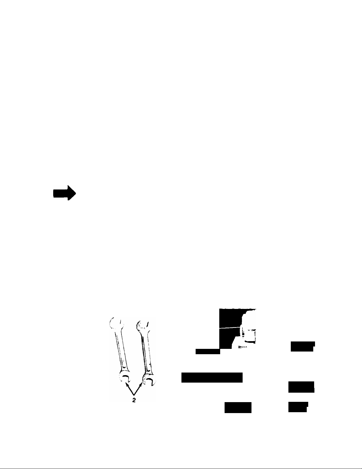
TOOLS REQUIRED: See Figure 1
1. (1) Vz” Socket, open or box wrench.
2. (2) 9/16" Socket, open or box wrench.
3. (1) V4" Flat Screwdriver.
8
3. Gas (regular)
4. Cleaning rag
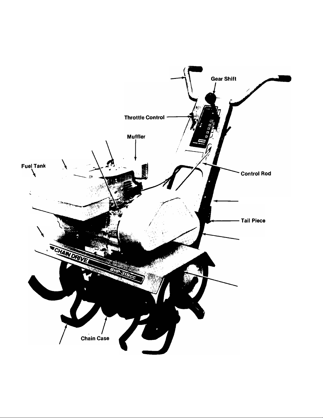
PARTS IN CARTON (See figure 2.)
Tail Piece
Handle—> á
Panel
^éar SbiM
Hardware
Pack
'S0¥p#
Stake
.Control
Pod
FIGURE 1.
FIGURE 2.
Page 5
IS
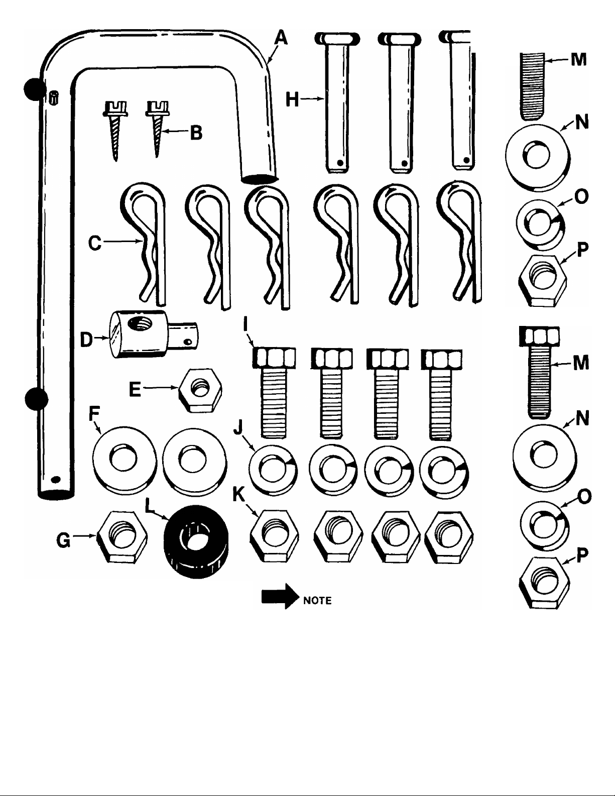
FIGURE 3. (SHOWN IN FULL SCALE)
LIST OF CONTENTS IN HARDWARE PACK:
A (1) “U”-Clevis Pin Vz” Dia.
B (2) Self Tapping Screws #8 x .62”
C (6) Hair Pin Cotters
D (1) Ferrule
E (1) Hex Center Locknut 5/16-18 Thread
F (2) Flat Washers
G (1) Hex Center Locknut 5/16-18 Thread
H (3) Clevis Pins
The letters listed below will be re
ferred to throughout the following
text for easier hardware identifica
tion.
I (4) Hex Screws 3/8-16 x 1.00”
J (4) Lockwashers 3/8”
K (4) Hex Nuts 3/8-16 Thread
L (1) Rubber Washer
M (2) Hex Screws 3/8-24 x 1.00"
N (2) Belleville Washer
O (2) Lockwashers 3/8”
P (2) Hex Nuts 3/8-24 Thread
Page 6
TILLER
IDENTIFICATION
Spark Plug
Oil Dipstick
Fuel Tank Cap
Handle Bar
Tine
Shield
Tine Assemblies
Depth Stake
Belt Cover
Wheel Yoke
Assembly
FIGURE 4.
Page 7
ASSEMBLY
INSTRUCTIONS
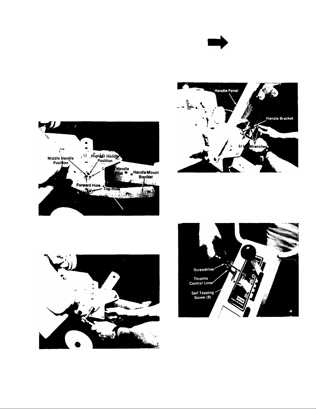
1. Handle Panel Attachment.
For shipping purposes, the handle mounting
brackets are pivoted down. With a 9/16” wrench
loosen the hex bolt holding the handle mount
brackets. See figure 5.
Pull handle mount brackets up so that the top hole
in bracket lines up with forward hole in chassis.
See figure 5.
NOTE
Do not tighten until all four bolts are
in place.
Four hex bolts (I), lockwashers (J) and hex nuts (K)
will be found in the hardware pack. See figure 7.
FIGURE 7.
2. Throttle Control Lever.
FIGURES.
Secure handle mount brackets with hex bolt (M),
belleville washer (N), lockwasher (O) and hex nut
(P). See figure 6.
FIGURE 6.
The handle panel is attached by sliding it down
over the handle brackets on the chassis and
installing four hex bolts in the lower holes of the
handle panel. Place bolts through the handle
panel; head to the outside. See figure 7,
Place throttle control lever up through the handle
panel and secure with two self tapping screws (B),
using a V4” flat screwdriver. See figured.
FIGURE 8.
3. Gear Shift Lever.
The shift lever is mounted to the handle panel in
the following steps.
A. Place the top hole of the shift lever over weld
bolt on handle panel. See figure 9.
B. Place one flat washer (F), rubber washer (L)
and the other flat washer (F) over weld bolt on
handle panel. See figure 9.
Page 8
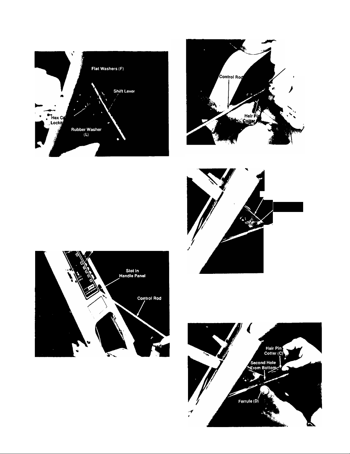
C. Secure with hex center locknut (G). See figure
9.
FIGURE 9.
H^^NOTE
Tighten hex locknut just to the point
the rubber washer starts to
conn press.
4. Control Rod.
A. Place control rod through slot in handle panel,
hook end of rod goes towards the front of
tiller. See figure 10.
t"
Pivot Arm
Assembly
/
FIGURE 11.
Shift Lever
Second Hole
From Bottom
FIGURE 10.
B. Hook control rod in hole provided on pivot arm
assembly as shown In figure 11. Secure
control rod to pivot arm assembly with hair pin
cotter (C). See figure 11.
C. Please note there are three holes left on the
shift lever. Use the second hole from bottom
for the next step. See figure 12.
FIGURE 12.
D. Place shift lever in first gear and thread ferrule
(D) on end of control rod until ferrule lines up
with second hole on shift lever. See figure 13.
Secure with hair pin cotter (C). See figure 13.
FIGUREIS.
Page 9
NOTE
Shift lever and control rod must be
readjusted whenever you change the
handle height.
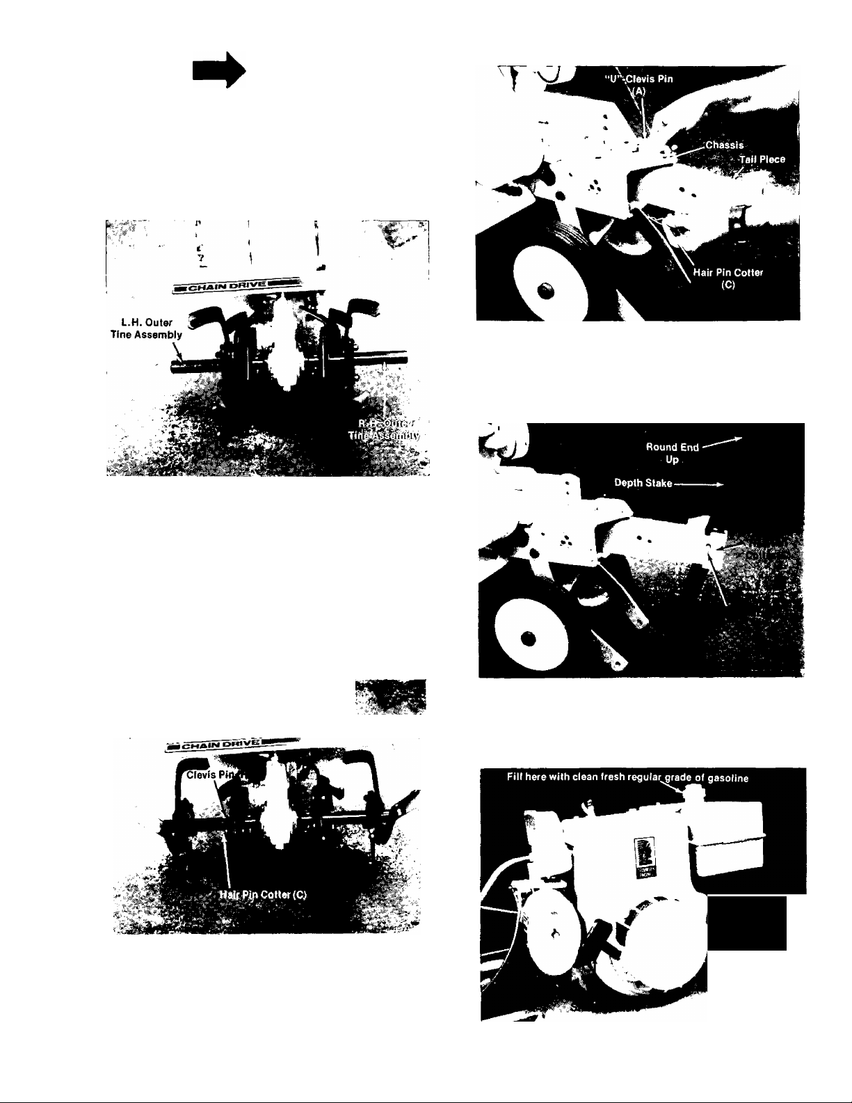
5. Tine Attachment
a. The outer tines have been reversed on the
tine shaft for shipping purposes. See
figure 14.
FIGURE 16.
7. Depth Stake Attachment.
Slide the depth stake into the tail piece (round end
up) and secure with clevis pin (H) and hair pin
cotter (C). See figure 17.
FIGURE 14.
Remove outer tines from the tine shaft and
reinstall with the tine hub facing inward as
illustrated in figure 15. Secure tines with clevis
pins (H) and hair pin cotters (C).
b. The inner tine assemblies have been
installed at the factory and in their correct
operating position and do not require
changing.
c. See tine adjustment for information on
changing width of tilling path, page 13.
I
FIGURE 17.
ENGINE
PREPARATION
FIGURE 15.
6. Tail Piece Attachment.
Slide the tail piece into the chassis and secure
with “U” clevis pin (A) and hair pin cotter (C). See
figure 16.
Oil Fill
Other Side of
Engine
FIGURE 18.
Page 10

OIL AND FUEL RECOMMENDATIONS
^CAUTION
A
Oil must be added before starting.
To start and operate your Tecumseh engine, you
wiil need the foliowing:
1. Fili crankcase with a clean, high quaiity deter
gent oii.
Be sure originai container is marked with
engine service classification “SC,” “SD,” or
“SE.”
For Summer (Above 32°F). Use SAE 30 oil.
(SAE 10W-30 or 10W-40 are acceptabie
substitutes.)
For Winter (Below 32°F). Use SAE 5W-30 oil.
(SAE 10W is an acceptable substitute.)
(Below 0“F Only) SAE 10W oil diluted with
10% Kerosene is acceptable.
Crankcase capacity is approximately 24
ounces (IV2 pints). See figure 19. Fill to full
mark on oil dipstick.
2. A fresh, clean, unleaded automotive gasoline.
(Leaded “Regular” grade gasoline is an
acceptable substitute.) See figure 20.
NEVER FILL FUEL TANK COMPLETELY. FILL
TANK TO WITHIN V4 TO INCH OF TOP OF
TANK TO PROVIDE SPACE FOR FUEL EXPAN
SION. WIPE ANY FUEL SPILLAGE FROM
ENGINE AND EQUIPMENT BEFORE STARTING
ENGINE.
NOTE
Use clean oil and fuel and store in
approved, clean covered containers.
Use clean fill funnels.
OPERATION
TO START ENGINE;
1. CAUTION: BE SURE NO ONE IS STANDING
IN FRONT OF THE TILLER WHILE THE
ENGINE IS RUNNING OR BEING STARTED.
FIGURE 19.
FIGURE 20.
FIGURE 21.
2. Place the shift lever in the neutral (N)
position. See figure 21.
FIGURE 22.
10
Page 11

3. Choke Engine. Push choke lever to choke
engine. See figures 22 and 23. Once the
engine starts, puil back on choke iever.
FIGURE 23.
4. Move the throttle control lever forward
FAST POSITION.See figure 24.
5. Stand at side of the tiiler, grasp the starter
handle and puil out rapidly. Return it slowly
to the engine. Repeat as necessary. See
figure 25.
If engine is warm, start with the con
trol in the “FAST” oosition. Choking
may not be necessary. See figure 24.
6. Move the throttle control to SLOW when
transporting the tiller. When the tiller is
being moved to or from the garden, the depth
bar should be pivoted forward until it engages
the depth bar retainer clip. The machine may
be moved under its own power, without
seriously damaging grass areas as long as it
is allowed to move freely. If the operator
to
holds back, it will start to dig.
CONTROLS
NOTE
FIGURE 24.
LOCATION AND USE.
1. Shift Lever; The shift lever is located on the
left hand side of the handle panel. Left hand
is determined from the operator’s position,
standing behind the tiller.
A. Forward (F)—Move the lever to the right
and down (Forward) to set unit in motion.
See figure 26.
B. Neutral (N)—Move lever to center detent.
See figure 24.
C. Reverse (R)—Pull the lever back (upward)
slowly and intermittently. See figure 27.
FIGURE 25.
FIGURE 26.
11
Page 12

2. Throttle Control: The throttle control lever is
located on the right hand side of handle
panel.
A. Stop—Pull lever back (upward) to stop the
unit. See figure 21.
B. Start—Push lever forward (down) to start
unit. See figure 22.
FIGURE 27.
TILLING
,1. Adjust depth bar by removing clevis pin and
hair pin cotter, changing bar position, then
replacing hair pin cotter and clevis pin. See
figure 17.
A. Lowering the depth bar will slow the tiller
and make it till deeper.
B. Raising the depth bar will allow the tiller
to move faster and till shallower.
C. For normal tilling, set depth bar at the fifth
or sixth hole from the top.
2. Adjust wheel yoke by removing clevis pin and
hair pin cotter, changing wheel yoke height,
and replacing clevis pin. See figure 17.
A. Raising the wheel yoke will allow the
tiller to till deeper.
B. Lowering the wheel yoke will allow the
tiller to till shallower.
C. For normal tilling set wheel height at the
second or third hole from the top.
Extremely wet soil will cause soil to ball up or
clump.
When tilling in the Fall, all vines and long grass
should be removed. This will prevent vines from
wrapping around the tine shaft which slows titling
operation.
1. The best method will be determined by the
soil condition. In some soils, the desired depth is
obtained the first time over the garden. In other
soils, the desired depth is obtained by going over
the garden two or three times. In the latter case,
the depth stake should be lowered before each
succeeding pass over the garden, and passes
should be made across the length and width of the
garden alternately. Rocks which are turned up
should be removed from the garden area.
2. Handle Pressure: Further control of tilling
depth and travel speed can be obtained by
variation of pressure on the handles.
When using the depth bar a downward pressure
on the handles will increase the working depth
and reduce the forward speed. An upward
pressure on the handles will reduce the working
depth and increase the forward speed. The type of
soil and working conditions will determine the
actual setting of the depth bar and the handle
ground, while the tiller is resting on the tines.
CULTIVATING
For cultivating, a two to three inch depth is
desirable. Setting the wheels and depth bar so
that the wheels are about two inches above the
ground, while the tiller is resting on the tines and
depth bar, will allow the machine to work at
cultivating depth. The throttle should be set to
control forward movement to a slow walking
speed. With standard tines, the working width of
the machine is 26 inches. See figure 28.
TILLING HINTS
Soil conditions are important for proper titling.
The tines will not readily penetrate dry, hard soil.
This may contribute to excessive bounce and
difficult handling of the tiller. Hard soil should be
moistened prior to tilling.
FIGURE 28.
12
Page 13

Tilling width can be increased from 26 inches to
28 inches by removing the clevis pin and hair pin
cotter and sliding the outer tines out one (1) inch,
and replacing the clevis pin and hair pin colter.
See figure 29.
The compost should be worked in to a depth of six
to eight inches. This may be done by working the
length of the garden, and then by mixing separate
passes across its width. The addition of decayed
organic matter will substantially increase the
fertility of your garden. For proper decaying
action, fertilizer should be applied and worked in
with the mulch materials. The breaking up of the
leaves and straw and the mixing of it with the
several inches of soil cause the soil to hold
moisture longer and allow proper aeration of the
plant root system. This also retards the growth of
weeds.
The U.S. Department of Agriculture and various
state and local agencies offer published booklets
and expert advice on all phases of gardening.
They should be consulted regarding soil informa
tion, planting dates, and the most satisfactory
varieties of crop for your particular area.
FIGURE 29.
For cultivation, this may be reduced to 14 inches
by removing the outer tines. See figure 30.
W ■
FiGURE 30.
In laying out plant rows be sure to allow enough
width (14” to 15”) to permit cultivation between
the rows.
In growing corn or similar crops, check-row
planting will permit cross cultivation and
practically eliminate hand hoeing. The tiller has
many uses other than tilling and cultivating a
garden. One of these is the preparation of lawn
area for seeding. The tiller will prepare a deep
seed bed which will be free of hard untilled spots,
allowing a better stand of grass to grow. The tiller
is very useful for loosening hard soil for
excavation with a shovel. Your tiller may be used
for mixing compost in the pile, or for mixing it
with the soil in your garden. This should be done
after the soil has been broken to the full working
depth.
MAINTENANCE
BELT REPLACEMENT:
If belt replacement is required order belt or belts
by part number from your nearest Sears Service
Center.
FORWARD DRIVE BELT - Part No. 754-0232
Vz” X 20” long
REVERSE DRIVE BELT - Part No. 754-0231
Vz” X 28” long
Your tiller has been engineered with the above
belts and should not be replaced with an
off-the-shelf belt. The above belts are of special
material (Kevlar Tensile).
Removing and replacing the REVERSE DRIVE
BELT.
1. Remove the belt cover, by removing two (2)
self tapping screws, and one (1) hex nut. See
figure 31.
FIGURE 31.
13
Page 14

2. Push forward on the idler and lift belt off of
chain case pulley, idler pulley and variable
speed pulley. See figure 32.
FIGURE 32.
Removing and replacing
the FORWARD DRIVE
BELT.
1. To remove the forward drive belt you must
remove the reverse drive belt first. See.
removing the reverse drive belt section, steps
1 and 2.
2. Push the shift lever forward and lift off belt
from variable speed pulley and engine pulley.
See figure 33.
Engine:
1. You MUST CHANGE THE OIL in the crankcase
after the first two hours of operation of your
new engine and after each 25 hours of use
thereafter to ensure proper lubrication of
internal parts for trouble free operation and to
prevent costly repair due to excessive wear.
(Take care to remove dirt around dip stick.) Be
sure oil level is maintained full to mark. See
figure 19.
To change oil remove drain plug (figure 34) and tip
the tiller forward while engine is warm. Replace
drain plug. Remove oil dip stick and refill with
new oil of proper grade. Replace dip stick.
4AIN DRIVE
aHR-3
FIGURE 33.
CARE AND MAINTENANCE:
Transmission:
The transmission is pre-lubricated and sealed at
the factory. It requires no additional lubrication
unless the transmission is disassembled. To fill
with grease, lay the left half of the chain case on
its side, add 14 ounces of Plastilube #1 grease and
assemble the right half to it. This grease can be
from your nearest Sears Service Center. (Order
Part No. 737-0133.)
FIGURE 34.
2. Always use the PROPER FUEL in your engine.
Useonlya good grade of fresh, clean, regular
gasoline. Do not use gasoline that has been
sitting for a long period of time. Stale
gasoline may cause engine to run poorly or
not at all.
3. Keep your engine CLEAN. Wipe off all spilled
fuel and oil. Keep the engine clean of foreign
matter and be sure the cooling fins on the
cylinder are kept clean to permit proper air
circulation. You must REMEMBER that this is
an air cooled engine and free flow of air is
essential to proper engine performance and
life.
4. Your must SERVICE YOUR AIR CLEANER.
Clean every 10 operating hours, or more often
if used in extremely dusty or dirty areas.
Proceed as follows:
A. Remove wing nut, cover and filter.
B. Tap top or bottom of filter lightly on a fiat
surface to dislodge any dirt (low pressure
air blown carefully from inside of filter
may also be used)—or wash filter in water
t4
Page 15
and detergent solution and flush from
inside until water is clear. Be sure filter is
completely dry before reassembling to
engine. DO NOT OIL FILTER. IF IT IS
PUNCTURED, TORN OR UNCLEANABLE,
IT SHOULD BE REPLACED. Replacement
filters are available at your nearest
Authorized Sears Service Center.
C. Before replacing filter, clean inside of
base and cover thoroughly.
D. Replace filter and cover making sure filter
is seated correctly between base and
cover. Tighten wing nut securely. See
figure 35.
NEVER RUN ENGINE WITHOUT COMPLETE AIR
CLEANER INSTALLED ON ENGINE.
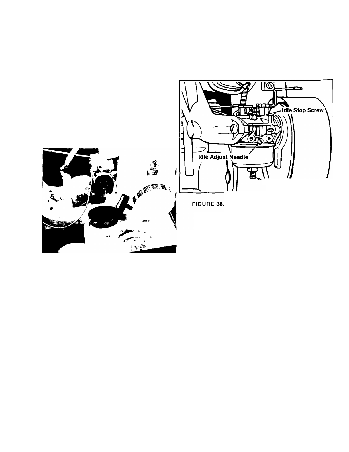
E. With engine running at idle speed, adjust
idle adjust needle 1 /8 turn at a time,
clockwise and counterclockwise, until
engine runs smoothly.
Allow several seconds between each
adjustment for engine to adapt to new
setting.
High Speed Adjust Needle
FIGURE 35.
ADJUSTMENTS
DO NOT MAKE UNNECESSARY ADJUSTMENTS.
FACTORY SETTINGS ARE SATISFACTORY FOR
MOST APPLICATIONS AND CONDITIONS. IF
ADJUSTMENTS ARE NEEDED, PROCEED AS
FOLLOWS:
1. Carburetor Adjustments (See figure 36.)
A. High speed adjust needle is pre-set at the
factory. (1V2 turns open)
Re-adjustment should not be necessary.
B. Close idle adjust needle by turning
clockwise. Close finger tight only. Forcing
may cause damage.
C. Open idle adjust needle by turning VA
turns counterclockwise.
D. Start engine. Follow preceding starting
instruction. Run engine a few minutes to
warm it up.
2. Remote Control Adjustments (See figure 37.)
To obtain satisfactory engine performance,
the engine and remote equipment controls
must be adjusted properly. If it is necessary
to check the engine control adjustments,
proceed as follows:
A. Set remote equipment control at FAST or
HIGH SPEED and keep it in this position.
With control in this position, control lever
should touch high speed stop. If it does,
the controls are adjusted correctly and no
fOTther adjustment should be necessary.
If control lever does not touch high speed
stop, proceed to Instruction B.
B. Loosen clamp screw just enough so remote
control cable can be moved in cable clamp
(do not remove cable clamp from control
bracket or disconnect. Remote control
cable from control lever).
C. Move control lever so it is touching high
speed stop and hold it in this position.
With control lever in this position, tighten
clamp screw so that cable clamp will hold
remote control cable in place when remote
equipment control is used.
The engine controls should now be
adjusted correctly.
15
Page 16

Control Bracket
/ mu
FIGURE 37.
3. NEVER TAMPER WITH ENGINE GOVERNOR
WHICH IS FACTORY SET FOR PROPER
ENGINE SPEED. OVERSPEEDING ENGINE
ABOVE FACTORY HIGH SPEED SETTING
CAN BE DANGEROUS. IF YOU THINK THE
ENGINE GOVERNED HIGH SPEED NEEDS
ADJUSTING, CONTACT YOUR NEAREST
AUTHORIZED SEARS SERVICE CENTER,
WHO HAS THE PROPER EQUIPMENT AND
EXPERIENCE TO MAKE ANY NECESSARY
ADJUSTMENTS.
SPARKPLUG:
1. Remove the spark plug each time you change
the oil and inspect it. See figure 38.
A. The electrodes should be kept clean and
free OF CARBON. The presence of carbon
or excess oil will greatly deter proper
engine performance.
B. If possible, check the spark plug gap (area
between electrodes) using a wire feeler
gauge. This specification should be .030.
2. if you need a spark plug refer to the yellow
pages of your phone book under “Engines Gas
oline" for an authorized dealer.
STORAGE
If the tiller is not to be used for a while, the
following procedure should be followed. The
tines, depth bar, transmission and wheels should
be cleaned of all dirt, it is very important that the
unit be stored in a level position to prevent engine
oil from draining into the cylinder head cavity.
Engines on tillers to be stored between seasons
should be completely drained of fuel to prevent
gum deposits forming on essential carburetor
parts, and fuel tank.
///^
TILLER INSTRUCTIONS FOR WINTER
OPERATION (under 40*F.)
Engine Lubrication. Drain the summer engine oil
while engine is warm. Refill with new “winter
grade” oil. Run engine until warm to distribute the
new winter oil.
Use oil “for service” SC, SD, or SE. Use 5W-20 or
5W-30. If not available, use 10W, or 10W-30.
Fuel. Replace any summer gasoline on hand or in
the fuel tank with fresh winter-grade gasoline. Use
lead-free or leaded “regular” grade automotive
gasoline. Winter fuels have additives for faster
starting. Keep fuel tank full.
NOTE
Many automotive gasolines no long
er contain “de-icer.” A can of gas
line de-icer fluid added to yourgasoline supply will help maintain the
engine’s winter reliability.
Cold Starting Hints
1. Be sure to use proper winter-grade oil and
gasoline.
2. Declutch all possible external loads.
3. Set governor control at low-speed position.
4. Turn carburetor needle valve approximately
1 /8 turn counterclockwise. (Richer fuel
mixture) This will improve cold weather
starting and operation.
16
Page 17

NOTES
17
Page 18

Repair Parts 8-H.P. Tiller Model 247.298760
18
29 27
Page 19

Repair Parts 8-H.P. Tiller Model 247.298760
REF.
NO.
10
11
12
13
14
15
16
17
18
19
20
21
22
23
24
25
26
27
1
PART
NO.
710-0160
Hex Wash. Hd. AB-Tapp Scr.
DESCRIPTION
#8 X .62” Lg.*
2
04777
3
4
5
01166
710-0253
715-0119
Handle Ass’y.
Grip
Hex Scr. 3/8-16 X 1.00” Lg.‘
Spring Roll Pin 5/32” Dia. x
1.12” Lg.
6
04602
7
710-0451
8
04586
9
711-0599
06811
714-0145
732-0322
736-0119
714-0145
712-0798
”U”-Clevis Pin .500” Dia.
Carr. Bolt 5/16-18 x .75” Lg.*
“□’’-Channel Plate
Clevis Pin
Depth Bar
Internal Cotter Pin
Depth Bar Spring Clip
L-Wash. 5/16” Scr.*
Internal Cotter Pin
Hex Nut 3/8-16 Thd.*
736-0169 L-Wash. 3/8” Scr*
06805
736-0105
710-0152
710-0118
Handle Brkt.—L.H.
Bell. Wash. 3/8” I.D.
Hex Scr. 3/8-24 X 1.00” Lg.*
Hex Sems Scr. 5/16-18 x
.75” Lg.*
736-0169
712-0241
736-0253
741-0116
734-0584
L-Wash. 3/8” Scr*
Hex Nut 3/8-24 Thd.*
Bell. Wash.
Flange Brg. w/Flats .631 I.D.
Wheel Ass’y. Comp.
738-0318 Shid. Bolt .625” Dia. x 2.75”
Lg. V2-2O Thd. 52
712-0267
Hex Nut 5/16-18 Thd.*
REF.
PART
NO.
28
29
30
31
32
NO.
736-0119
736-0921
L-Wash. 5/16” Scr*
L-Wash. 1/2” Scr*
712-0239 Hex Cent. L-Nut V2-20 Thd.
06813
06792
Wheel Yoke Ass’y.
Engine “U”-Channel Ass’y.—
DESCRIPTION
L.H.
33
34
712-0267
710-0322
Hex Nut 5/16-18 Thd.*
Hex Sems Scr 5/16-18 x
1.00” Lg.
06794
35
Engine “U”-Channel Ass’y.—
R.H.
36
06806 Handle Brkt.—R.H.
37
38
39
40
41
42
43
711-0599
736-0119
712-0267
06816
712-0267
06807
710-0599
Clevis Pin
L-Wash. 5/16” Scr*
Hex Nut 5/16-18 Thd.*
“□’’-Channel Brkt. Ass’y.
Hex Nut 5/16-18 Thd.*
Tail Piece
Thread Rolling Scr. V4-20 x
.50” Lg.
44
712-0158
45
736-0159
46
735-0126 Rubber Wash.
47
747-0271
48
04810
49
746-0272
Hex Cent. L-Nut 5/16-18 Thd.
FI-Wash. .344 I.D. x .87” O.D.
Control Rod
Shift Lever
Throttle Control Ass’y.
Comp.
50
714-0145 Internal Cotter Pin
51
53
711-0198
731-0189
720-0183
Ferrule
Knob—Throttle Control
Ball Knob—Shift Lever
•Standard Hardware Items—May Be Purchased Locally.
19
Page 20

Repair Parts 8-H.P. Tiller Model 247.298760
-----
29
—30
31
20
Page 21

Repair Parts 8-H.P. Tiller Model 247.298760
REF.
NO.
10
11
12
13
14
15
16
17
18
19 04900
20
21
1 22
23
24
25
26
27
PART 1
NO.
1 .
^52-0663 Engine Tecumseh Model
DESCRIPTION
HM80-15162E
2
710-0599 Thread Rolling Scr. V4-20 x .62” Lg.
.50” Lg.
3
04899 Belt Cover
4
04896
Front Belt Guard Support
Ass’y.
5
6
7
8
9
736-0114
710-0121
717-0390
736-0142
756-0313
Internal L-Wash. V2” Dia.
Hex Scr. V2-20 X .15 Special
Variable Speed Pulley Ass’yFI-Wash. .281 I.D. x .50O.D.
X .63
Idler Pulley
712-0262 Hex Jam Nut 3/8-24 Thd.
756-0305
Pulley 4.50” Dia.
736-0231 FI-Wash. 5/16” I.D. x 1.120”
O.D.
736-0119
710-0573
L-Wash. 5/16” Scr.* 43
Hex Scr. 5/16-18 x 1.25” Lg.*
710-0230 Hex Scr. V4-28 x .50” Lg.*
754-0231
754-0232
712-0239
“V”-Belt V2” X 28” Lg.
”V”-Belt V2” X 20” Lg.
L-Nut V2-2O Thd.
Friction Wheel Ass’y.
710-0191
736-0169
736-0258
Hex Scr. 3/8-24 x 1.25” Lg.*
L-Wash. 3/8” Scr.*
FI-Wash. 3/8” I.D. x 1.00”
O.D.
756-0306
714-0133
750-0229
Engine Pulley
Sq. Key 3/16 x 1.50” Lg.
Spacer .635” I.D. x .88 O.D. x
1.035” Lg.
732-0376
710-0599
Extension Spring
Hex Tapp Scr. V4-20 x .50”
Lg.
REF.
NO.
30 10844
PART
NO.
28
04898
29
715-0124 Spring Pin Spiral 5/32 Dia. x
Belt Guard Support—Rear
DESCRIPTION
Sheave Half
31 741-0139 Ball Bearing
32
750-0146 Spacer
33 04893
34 747-0271
35
738-0140
36
711-0494
37
710-0515
714-0115
38
Idler Arm Ass’y.
Control Rod 3/8” Rod *
Shid. Bolt .437 Dia. x .180
Spacer .510 I.D. x .760 O.D.
X .390” Lg.
Hex Scr. V2-2O X 3.50” Lg.
Cotter Pin 1/8” Dia.*
39 04889 Pivot Arm Ass’y.
40
714-0145 Internal Cotter Pin V2” Dia.
41 711-0599
42
742-0175
742-0174
44
06797 Outer Tine Adapter Ass’y.
45
04695 Outer Tine Ass’y. Comp.—
Clevis Pin
Tine—L.H.
Tine—R.H.
L.H.
46
712-0241 Hex Nut 3/8-24 Thd.*
47
736-0169
48
710-0191 Hex Scr. 3/8-24 x 1.25” Lg.*
49
06821
L-Wash. 3/8” Scr.*
Inner Tine Ass’y. Comp.—
L.H.
50 06798 Inner Tine Adapter Ass’y.
51 712-0267
52 736-0170
53 06822
Hex Nut 5/16-18 Thd.*
Shakeproof Washer
Inner Tine Ass’y. Comp.—
R.H.
54
04696
Outer Tine Ass’y. Comp.—
R.H.
55
04776 Tine Shield
56
710-0442
Hex Scr. 5/16-18 x 1.50” Lg.*
•Standard Hardware Items—May Be Purchased Locally.
TILLER ACCESSORIES
Til-Row Attachment 8” Furrower
Leveling/Snow-Blade Kit
V-Bar Cultivating Kit
Drag Stake Cultivating Kit Cultivating Shields
V-Bar Frame
4-pt. Cultivator Tines 13 X 5.00—6 Pneumatic Traction Tires
Hiller/Furrower
Depth Gauge Wheels
6-Tang Universal Cult.
Drag Stake
THESE ACCESSORIES ARE AVAILABLE IN THE
SEARS BIG SPRING CATALOG..
21
15” Sweep Cult./Hoe
32” Leveling Rake
32” Leveling/Snow-Blade
Wheel Weights
Tire Chains (Pr.)
Wheel Weights F/Leveling Snow-Blade
Page 22

Repair Parts 8-H.P. Tiller Model 247.298760
28fO|' f 29 30 3) 1
NOTE: Use 14 ounces of
Plastilube #1
Order Part No. 737-0133
Repair Parts Transmission 04907
REF.
NO.
1
2
3
4
5
PART
NO.
750-0315
738-0182
721 -0132
04885
741-0155
COLOR
CODE
DESCRIPTION
Spacer .657 I.D. x .78 O.D.
X 2.19
Jack Shaft
Gasket for Housing
Housing Half—L.H.
Bail Bearing .625 I.D. x
NEW
PART
REF.
N
1.375 O.D.
05034
6
7
750-0229
756-0264
8
Bearing Housing
Spacer .625 I.D. x .88 O.D.
X1.035
Chain Case Pulley 6.00”
Dia. (380)
756-0262
Chain Case Pulley 6.00”
Dia. (385)
9
710-0643 Hex Scr. 5/16-18x1.00”
Lg. Special
10
736-0119
11
736-0231 FI-Wash. 5/16 I.D. X 1.125
L-Wash.5/16” Scr.*
O.D. x .125
12
710-0599 Hex Wash. Hd. Self Tapp.
Scr. V4-20 x .50” Lg.
14
712-0267 Hex Nut 5/16-18 Thd.“*
710-0644 Hex Scr. 3/8-16 X 3.25” Lg.
15
721-0102
16
17
712-0138 Hex Nut V4-28Thd.*
736-0329
18
19
736-0259 FI-Wash. 1.0” I.D. X 1.62
Oil Seal 1” I.D. X 1.357 O.D.
L-Wash. V4” Scr.*
O.D. X.090
20
750-0314
'For faster service obtain standard nuts, bolts, and washers locally. If these items cannot be ob
tained locally, order by part number and size as shown on parts list.
Spacer 1.0”I.D.x 2.0” O.D.
X.68
22
PART
36
NO.
06800
710-0195
721 -0133
741-0198
712-0798
736-0169
710-0322
710-0538
04886
748-0229
713-0206
713-0131
713-0186
748-0855
713-0187
738-0320
NO.
21
22
23
24
25
26
27
28
29
30
31
32
33
34
35
37 713-0182
713-0181
38
738-0308
39
715-0114
40
714-0133
41
COLOR
CODE
DESCRIPTION
Tine Shaft Ass’y.
Hex Scr. V4-28x.62”Lg.‘
Gasket for Bearing Hsg.
Bearing Housing Ass’y.
HexNut3/8-16Thd.*
L-Wash.3/8” Scr.*
HexSemsScr. 5/16-18x
1.00” Lg.*
Hex Scr. 5/16-18 x .62”
Lg. Special
Housing Half—R.H.
Hex Flanged Bearing .630
I.D.
Sprocket 10 Teeth x .500
Pitch
#41 Chain V2” Pitch x 33
Links Endless
#42 Chain V2” Pitch x 48
Links Endless
Flange Bearing .628 I.D.
#50 Chain 5/8” Pitch x 28
Links Endless
Sprocket Shaft
Sprocket Bearing Sleeve
Ass’y.
Sprocket Sleeve Ass’y.
Sprocket Shaft
Spring Pin Spiral V4” Dia.
X1.5” Lg.
Sq. Key 3/16 X1.50” Lg.
NEW
PART
N
Page 23

TE CU MSE H 4- aCL E EN GIN E
MODEL NUMBER: HM80-155162E
126
124
92-^\76'^-d^
82 83 >
97- 77 161
/ti -7
128 149
23
Page 24

TE CU MSE H 4- acU E NG INE
MODEL NUMBER: HM80-155162E
Ref.
No.
10
11
12
13
14
15
16
17
19
20
21
22
22
22
23
24
24
24
25
26
27
28
29
30
31
32
33
34
35
36
37
38
39
40
41
42
43
43
44 27878A
44 27880A
45
46
47
48
50
51
52
53
54
Part Ref.
No.
1
2
3
4
5
6
7
8
9
55
56
34348
27652
32630
27642 Plug, Oil drain
30699C
30700 Yoke, Governor
650494
29642
29916
29826
29216 Nut, Square, 10-32
650548
33364 Lever, Governor
29918
30322 Nut & Lockwasher., 8-32
29536
650561
33365B
29783
33245 Gear, Crankshaft
34329 Piston, Pin & Ring Assy. (Std.) (Incl.
34330
34331
27888
34332
34333
34334
32591C
650662A
34242
34034
34143
*33253 Gasket, Cylinder cover
33367A Cover, Cylinder (Incl. Nos. 32, 33 &
33368
31950
31845 Shaft, Mechanical governor
30588A
29193
30591
33369
28763
30590A Washer, Flat
650488
650493
34035
34036
27882
27881
32581
650489
34235
32589
650737 Screw, Hex washer hd. taptite, 1/4-20
33662
650490
34030
8116
Part Name
Cylinder Assy, (Incl. Nos. 2,3&4)
Pin, Dowel
Seal, Oil
Rod Assy., Governor (Incl. Nos. 6&
7)
Screw, Fil. hd. Sefns, 6-40x 5/16
Ring, Retaining
Clamp, Governor lever
Screw, Hex washer hd., 10-32 x 3/4
Screw, Hex washer hd., 8-32 x 5/16
Lockwasher, No. 8 E.T.
Baffle, Blower housing
Screw, Hex hd. Sems, 1 /4-20 x 5/8
Crankshaft Assy. (Incl. Nos. 20&21)
Pin, Crankshaft gear
Nos. 23&24)
Piston, Pin & Ring Assy. (.010 oversize) (Incl. Nos. 23& 24)
Piston, Pin 8e Ring Assy. (.020 oversize) (Incl. Nos. 23& 24)
Ring, Piston pin retaining
Ring Set, Piston (Std.)
Ring Set, Piston (.010 oversize)
Ring Set, Piston (.020 oversize)
Rod Assy., Connecting (Incl. Nos. 26
&27)
Bolt, Connecting rod
Dipper, Oil
Lifter, Valve
Camshaft (Mech. Compression Release)
34)
Bushing, Crankshaft
Seal, Oil
Spool, Governor
Ring, Retaining
Gear Assy., Governor (Incl. No. 40)
Bracket, Governor gear
Screw, Hex washer hd. shakeproof.
10-32 X 19/32
Screw, Hex hd. Sems, 1/4-20 x 1-1/4
Screw, Hex hd. Sems, 1/4-20 x 1-3/4
Valve, Intake (Std.) (Incl. No. 47)
Valve, Intake (1/32" oversize) (Incl.
No. 47)
Valve, Exhaust (Std.) (Incl. No. 47)
Valve, Exhaust (1/32"oversize) (Incl.
No. 47)
Cap, Upper valve spring
Spring, Valve
Cap, Lower valve spring
Screw, Hex hd. Sems, 1/4-20x 5/8
Wire, Ground
Key, Flywheel
X 1/2
Hub & Screen Assy., Starter
Washer, Belleville
Nut, Hex
Head, Cylinder
Part
No.
57
58 6021A
59 650727
60 650691
61 33272
63
65
65
66
67
68
69
70
71
72
73
74
75
76
77
78
79
80
81
82
83
84
85
86
87
88
89
90
91 650788
92
93
94
95
96
97
108
109
110
112
115
119
120
121
122
123
124
126
128
143
144
145
146
147
No.
*34031
650713
33636 Plug, Spark (Champion J-8 or equiva-
34251
Canada tions require RJ-17LM resistor spark
28423
28424
*27896
28425
27627
650128
*27915
33877
650378
*33861
30088A
29752
30705 Line, Fuel
26460
33876
33461A Control Assy., Speed (Incl. Nos. 82,
650549
31342
33371
33878
33374
27793
28942
33375B
29747A
610973
33013
650760
33273
650128
29919
34154
34155
650665
650561
29752
33756
650729
31E38
31297
*29673
34156
32387A
34374
28820
*27272
33266
33268
33269A
Part Name
Gasket, Cylinder head
Screw, Hex hd. cap, 5/16-18 x 1-1/2
Screw, Special hex hd. tapped.
5/16-18x1-3/4
Washer, Flat
Cover, Cylinder head
Screw, Hex hd., 5/16-18 x 5/8
lent) Exceotfor Canada
Resistor Spark Plug (Canadian Regula-
plug)
Body, Breather
Element, Breather
Gasket, Breather cover
Cover, Valve spring
Tube, Breather
Screw, Fil. slotted hd. Sems, 10-24 x
1/2
Gasket, Intake pipe
Pipe,Intake
Screw, Fil, hd. Sems, 5/16-18 x 1-1/8
Gasket, Carburetor
Screw, Fil. hd. Sems, 1 /4-28 x 1
Nut& Lockwasher, 1/4-28
Clamp, Fuel line
Gasket, Stator
83, 86&92)
Screw, Fil. hd., 5-40x 7/16
Spring, Compression
Link, Governor lever-to-bellcrank
Link, Governor lever-to-throttle
Spring, Extension
Clip, Conduit
Screw, Hex hd. Sems, 10-32 x 3/8
Housing, Blower
Screw, Hex hd. Sems, 5/16-24 x 3/4
Screw, Hex hd. spin-lock thread
forming, 5/16-18 x 3/4
Terminal Assy.
Cover, Starter bubble
Screw, Pan hd., taptite, 8-32 x 7/16
Extension, Blower housing
Screw, Fil. slotted hd. Sems, 10-24 x
1/2
Screw, Hex washer hd. Sems, taptite.
8-32 x 1/2
Plate, Fuel tank mounting
Bracket, Tank mounting
Screw, Hex washer hd. Sems, self-tap,
1/4-14x7/8
Screw, Hex hd. Sems, 1 /4-20 x 5/8
Nut& Lockwasher, 1/4-28
Muffler
Screw, Hex hd., 5/16-18 x 3-3/16
Plate, Muffler locking
Dipstick, Oil (Incl. No. 123)
Gasket, Dipstick
Tank Assy., Fuel (Incl. No. 126)
Cap, Fuel filler
Decal, Instruction
Screw, Fil. hd. Sems, 10-32 x 1/2
Gasket, Air cleaner
Bracket, Air cleaner
Element, Air cleaner
Cover, Air cleaner
* Indicates Parts Included in
Gasket Set, Ref. No. 165.
24
Page 25

TK UM SEH 4 -a OE EN GI NE
Ref.
No,
148
149
161
162
Part
No,
33267
650513
631979
610842
Part Name
Bracket, Air cleaner
Nut, Wing, 1/4-20
Carburetor (Incl. No. 75)
Magneto (The complete magneto is
not available as an assembly. The
magneto number is shown for refer
ence purposes only. Order component
parts individually, as shown in parts
list.)
MODEL NUMBER: HM80-155162E
Ref.
No.
163
165
Part
No.
590479
33279C
694138
Part Name
Starter, Rewind
Gasket Set (Incl. items marked *)
Owners Manual
^IndicatesParts Included in
Gasket Set, Ref. No. 165.
CARBURETOR NO. 631979
I > I
\ I
*io23ol '
24 ”
—
Ref.
No.
6 650417
8 630735
9 631753
Part
No.
631979 Carburetor
631776
1
631970
2
3 631778
4
650506
630766 Spring, Idle regulating screw
5
5A
630738
7
631812 Shaft & Lever Assy., Choke
Shaft & Lever Assy., Throttle
Spring, Throttle return
Shutter, Throttle
Screw, Rd. hd., 4-40 x 3/16
Spring, Main adjustment screw
Screw, Idle regulating
Spring, Choke return
Shutter, Choke
Part Name
10 *630748 Plug, Welch
11 *631027 Plug, Welch
12 *631021
13 631022 Clip, Inlet needle
14
632019 Float, Carburetor
*631024
15
16 631867 Bowl, Float
17 632043 Spring
Inlet Needle, Seat & Clip Assy.
(Incl. No. 13)
Shaft, Float
18 631183 Washer, Felt
21 27110
22
*631583
23 630740
24
*630898 Screw, Idle adjustment
25 *631028
631803
26
27
631184 Washer
28 631972
29 631971
30
630739 Washer, Flat
31 631978
Gasket, Bowl-to-body
Adjustment Screw Assy., Main
(Incl. Nos. 5A,21,23&30)
"0" Ring, Adjustment screw
Gasket, Bowl-to-body
Fuel Fitting
Retainer, Seal
Seat, Oust
Repair Kit (Incl. items marked *)
25
Page 26

MAGNETO NO. 610842
The complete magneto is not
available as an assembly. The
.magneto number is shown for
reference purposes only. Order
component parts individually,
as shown in parts list.
Ref.
No.
1 610841
lA 610934
2
3
4
6
7
8
9
10
11
13
14
15
16
17
14
18
20
Part
No.
610842
30551
610947
610957
30547A
610385 Washer, Terminal
610408 Nut, Terminal
29181 Screw and Washer Assembly,
610593
33356 Tab, Ground terminal
30560A Coil Assembly (Incl. No. 14)
30554 Wire, Ignition lead
30548A
30545
305618
30549
31311
Magneto
Flywheel (Inch No. 1A)
Fan
Spripig, Breaker box dust cover
Cover, Oust
Gasket, Dust cover
Breaker Assembly
Breaker
Screw, Condenser fastening
Condenser
Core and Plate Group
Stator Assembly (Incl. Nos. 2, 3,
4, 6 thru 16,18 & 20)
Felt, Cam wiper
Clip, Coil lodKing
Part Name
REWIND STARTER NO. 590479
Ref.
No.
1
2
3
4
5
6
7
8
9
10
11
12
Part
No.
590479
590480
590481
590482
32024
590483
590484
590485
590486
590456
590487
590387
590488
Part Name
Rewind Starter
Screw, Center
Cam, Dog
Spring, Brake
Washer, Brake
Ring, Retainer
Dog
Spring, Dog
Pulley & Bearing Assy.
Rope, Starter
Spring & Keeper Assy.
Handle Assy., Starter
Housing Assy., Starter
26
Page 27

Page 28

owners
manual
HOW TO ORDER
REPAIR PARTS
The Model Number will be found stamped on a plate attached to the
chassis. Always mention the Model Number when requesting service or
repair parts for your tiller.
All parts listed herein may be ordered through SEARS ROEBUCK AND CO.
or SIMPSON SEARS LIMITED RETAIL or CATALOG STORE.
WHEN ORDERING REPAIR PARTS, ALWAYS GIVE THE FOLLOWING
INFORMATION AS SHOWN IN THIS LIST.
1. The PART NUMBER
2. The MODEL NUMBER 247.298760
3. The PART DESCRIPTION
4. The NAME OF MERCHANDISE- Tiller
MODEL NO.
247.298760
Sears
SERVICE
is at
Yoar
SERVICE
If the parts you need are not stocked locally, your order will be
electronically transmitted to a Sears Repair Parts Distribution Center for
expedited handling.
Your Sears merchandise takes on added value when you discover that Sears
has over 2,000 Service Units throughout the country. Each is staffed by
Sears-trained, professional technicians.
SBARa ROEBUCK AND GO.» ChicsaeoJlL 60684 UJSLA.
PART NO. 770-7762
PRINTED IN U.S.A.
 Loading...