

Page 1
perator s
P R 0 F E S S I 0 N A
GARDEN TRACTOR
28 HP, 54" Tractor
Electric Start
PGT9000
Model No. 247.289842
= EspaSol, p. 63
This product has a low emission engine which operates differently
from previously built engines. Before you start the engine, read and
understand this Operator's Manual.
iMPORTANT:
Read and foJlow aJJSafety
RuJes and instructions before
operating this equipment.
Sears Brands Management Corporation, Hoffman Estates, IL 60179 U.S.A.
Visit our website: www.craftsman.com FormNo.769-%507A
For answers to your questions about
this product, Call:
1=800=659=5917
CraftsmanTractorHelpLine
5am = 5 pro, Mort =Sat
(January7,2011)
Page 2
Warranty Statement .......................................................... 2
Safety Instructions ............................................................ 3
Slope Guide ....................................................................... 8
Safety Labels .................................................................... 9
Assembly ......................................................................... 10
Know your Lawn Mower .................................................. 13
Operation ........................................................................ 16
Service and Maintenance .............................................. 19
Off-Season Storage ........................................................ 30
Troubleshooting .............................................................. 31
Parts List ......................................................................... 34
Espa_oi ............................................................................ 63
Service Numbers ............................................. Back Cover
CRAFTSMAN PROFESSIONAL FULL WARRANTY
FORTWOYEARSfromthedateof purchase,all non-expendablepartsofthis ridingequipmentarewarrantedagainstanydefectsinmaterialor
workmanship.Adefectivenon-expendablepartwill receivefreein-homerepairor replacementif repairis impossible.
FORFiVEYEARSfromthedateofpurchase,theframeandfrontaxleofthis ridingequipmentarewarrantedagainstanydefectsinmaterialor
workmanship.Adefectiveframeorfrontaxlewillreceivefreein-homerepairorreplacementif repairisimpossible.
All oftheabovewarrantycoverageappliesforonly oneyearfromthedateof purchaseifthisridingequipmentiseverusedwhileproviding
commercialservicesor ifrentedto anotherperson.
FOR90 DAYSfromthedateof purchase,the battery(anexpendablepart)of this ridingequipmentiswarrantedagainstanydefectsin materialor
workmanship(ourtestingprovesthatitwillnot holdacharge).A defectivebatterywillreceivefreein-homereplacement.
ADDITIONALLIFETIMELIMITEDWARRANTYon CASTIRONFRONTAXLE(if equipped)
FORASLONGASiT iSUSEDbytheoriginalownerafterthefifthyearfromthedateof purchase,
thecast ironfrontaxle (if equipped)ofthisridingequipmentiswarrantedagainstanydefectsin material
or workmanship.Withproofofpurchase,a defectivecastfrontaxlewill receivefreein-homereplacement.
WARRANTYSERVICE
Forwarrantycoveragedetailsto obtainfreerepairor replacement,call 1-800-659-5917or visittheweb site:www.craftsman.corn
Inall casesabove,if part repairor replacementisimpossible,the ridingequipmentwill bereplacedfreeof chargewiththesameor anequivalent
model.
ThiswarrantycoversONLYdefectsinmaterialandworkmanship.WarrantycoveragedoesNOTinclude:
• Expendableparts(exceptforbattery)thatcanwearoutfromnormalusewithinthewarrantyperiod,includingbut notlimitedtoblades,
sparkplugs,air cleaners,belts,andoil filters.
• Standardmaintenanceservicing,oil changes,ortune-ups.
• Tirereplacementor repaircausedby puncturesfromoutsideobjects,suchas nails,thorns,stumps,orglass.
• Tireorwheelreplacementor repairresultingfromnormalwear,accident,orimproperoperationor maintenance.
• Repairsnecessarybecauseofoperatorabuse,includingbut not limitedtodamagecausedbytowingobjectsbeyondthecapabilityof
theridingequipment,impactingobjectsthatbendthe frame,axleassemblyorcrankshaft,orover-speedingtheengine.
• Repairsnecessarybecauseofoperatornegligence,includingbutnotlimitedto,electricalandmechanicaldamagecausedbyimproper
storage,failuretouse thepropergradeandamountofengineoil, failureto keepthedeckclearofflammabledebris,or failureto
maintaintheridingequipmentaccordingtotheinstructionscontainedin theoperator'smanual.
• Engine(fuel system)cleaningorrepairscausedbyfueldeterminedto be contaminatedoroxidized(stale).Ingeneral,fuelshouldbe
usedwithin30daysofits purchasedate.
• Normaldeteriorationandwearoftheexteriorfinishes,or productlabelreplacement.
Thiswarrantygivesyouspecificlegal rights,andyoumayalso haveotherrightswhichvaryfromstateto state.
SearsBrands ManagementCor
_oration,Hoffman Estates, IL 60179
EngineOil: SAE30
Fuel: UnleadedGasoline
SparkPlug: Champion@RC12YC
Engine: Briggs& StrattonProfessionalSeries
© KCDIP,LLC 2
Model Number
Serial Number
Dateof Purchase
Recordthe modelnumber,serialnumber,
anddateof purchaseabove.
Page 3
Thissymbolpointsout importantsafetyinstructionswhich,if not
followed,couldendangerthepersonalsafetyand/orpropertyof
yourselfandothers. Readandfollowallinstructionsin thismanual
beforeattemptingtooperatethismachine.Failuretocomplywith
theseinstructionsmayresultin personalinjury.Whenyou seethis
symbol,HEEDITSWARNING!
Thismachinewasbuilttobeoperatedaccordingtothe safeopera-
tionpracticesinthis manual.Aswithanytypeof powerequipment,
carelessnessorerroron the partofthe operatorcanresultin serious
injury.Thismachineiscapableofamputatingfingers,hands,toes
andfeetandthrowingdebris.Failuretoobservethefollowingsafety
instructionscouldresultin seriousinjuryordeath.
CALIFORNIA PROPOSITION 65
EngineExhaust,someof itsconstituents,andcertainvehicle
componentscontainoremitchemicalsknowntoStateof California
tocausecancerandbirthdefectsorother reproductiveharm.
Batteryposts,terminals,and relatedaccessoriescontainleadand
leadcompounds,chemicalsknowntotheStateof Californiato
causecancerandreproductiveharm.Washhandsafterhandling.
GENERAL OPERATION
• Read,understand,andfollowall instructionson the machineand
in themanual(s)beforeattemptingtoassembleandoperate.
Keepthis manualinasafeplaceforfutureand regularreference
andfororderingreplacementparts.
• Befamiliarwithall controlsandtheirproperoperation.Knowhow
tostopthemachineanddisengagethemquickly.
• Neverallowchildrenunder14yearsoldtooperatethis machine.
Children14yearsoldandover shouldreadandunderstandthe
operationinstructionsandsafetyrulesinthismanualandshould
betrainedandsupervisedbya parent.
• Neverallowadultstooperatethismachinewithoutproper
instruction.
• Tohelpavoidbladecontactora thrownobjectinjury,keep
bystanders,helpers,childrenandpetsatleast75feetfromthe
machinewhile itisin operation.Stopmachineifanyoneenters
thearea.
• Thoroughlyinspectthe areawheretheequipmentistobe used.
Removeallstones,sticks,wire,bones,toys,andotherforeign
objectswhichcouldbe pickedupandthrownby theblade(s).
Thrownobjectscancauseseriouspersonalinjury.
• Planyour mowingpatterntoavoiddischargeof materialtoward
roads,sidewalks,bystandersandthe like.Also,avoiddischarg-
ingmaterialagainstawallorobstructionwhichmaycause
dischargedmaterialto ricochetbacktowardthe operator.
Your Responsibility--Restricttheuseofthispowermachineto
personswhoread,understandandfollowthewarningsandinstruc-
tionsin thismanualandon the machine.
SAVE THESE INSTRUCTIONS!
• Alwayswearsafetyglassesor safetygogglesduringoperation
andwhileperformingan adjustmentorrepairto protectyoureyes.
Thrownobjectswhichricochetcancauseseriousinjurytothe
eyes.
• Wearsturdy,rough-soledworkshoesandclose-fittingslacksand
shirts.Loosefittingclothesandjewelrycanbe caughtin movable
parts.Neveroperatethismachineinbarefeetorsandals.
• Beawareofthemowerandattachmentdischargedirectionand
do notpointit at anyone.Donotoperatethemowerwithoutthe
dischargecoverorentiregrasscatcherin its properplace.
Donot puthandsorfeetnearrotatingpartsor underthe cutting
deck.Contactwiththe blade(s)canamputatehandsandfeet.
A missingordamageddischargecovercancausebladecontact
or thrownobjectinjuries.
• Stoptheblade(s)whencrossinggraveldrives,walks,orroads
andwhilenotcuttinggrass.
• Watchfortrafficwhenoperatingnearorcrossingroadways.This
machineis notintendedforuseonanypublic roadway.
• Donotoperatethemachinewhileunderthe influenceofalcohol
or drugs.
• Mowonlyindaylightorgoodartificiallight.
Nevercarrypassengers.
• Disengageblade(s)beforeshiftingintoreverse.Backupslowly.
Alwayslookdownandbehindbeforeandwhilebackingtoavoida
back-overaccident.
3
Page 4
• Slowdownbeforeturning.Operatethemachinesmoothly.Avoid
erraticoperationandexcessivespeed.
Disengageblade(s),setparkingbrake,stopengineandwaituntil
theblade(s)cometoa completestopbeforeremovinggrass
catcher,emptyinggrass,uncloggingchute,removinganygrassor
debris,or makinganyadjustments.
Neverleavea runningmachineunattended.Alwaysturnoff
blade(s),setparkingbrake,stopengineandremovekeybefore
dismounting.
Useextracarewhenloadingorunloadingthemachineintoa
trailerortruck.Thismachineshouldnotbedrivenupordown
ramp(s),becausethemachinecouldtip over,causingserious
personalinjury.Themachinemustbe pushedmanuallyon
ramp(s)to loador unloadproperly.
Mufflerandenginebecomehotandcancausea burn.Donot
touch.
Checkoverheadclearancescarefullybeforedrivingunderlow
hangingtree branches,wires,dooropeningsetc.,wherethe
operatormaybestruckor pulledfromthemachine,whichcould
resultinseriousinjury.
Disengageallattachmentclutchesanddepressthebrakepedal
completelybeforeattemptingto startengine.
Yourmachineisdesignedto cutnormalresidentialgrassofa
heightnomorethan10".Donot attempttomowthroughunusually
tall,drygrass(e.g.,pasture)orpiles ofdryleaves.Drygrassor
leavesmaycontacttheengineexhaustand/orbuilduponthe
mowerdeckpresentinga potentialfirehazard.
Useonlyaccessoriesandattachmentsapprovedfor this machine
bythe machinemanufacturer.Read,understandandfollowall
instructionsprovidedwiththe approvedaccessoryorattachment.
Fora list of approvedaccessoriesandattachments,call 1-800-
659-5917.
Dataindicatesthatoperators,age60yearsandabove,are
involvedin a largepercentageofridingmower-relatedinjuries.
Theseoperatorsshouldevaluatetheirabilitytooperatetheriding
mowersafelyenoughto protectthemselvesandothersfrom
seriousinjury.
If situationsoccurwhicharenotcoveredinthismanual,usecare
andgoodjudgment.Contact1-800-659-5917forinformationand
assistance.
SLOPE OPERATION
Slopesarea majorfactorrelatedtolossof controlandtip-over
accidentswhichcanresultinsevereinjuryor death.Allslopesrequire
extracaution.Ifyoucannotbackupthe slopeor ifyoufeel uneasyon
it, do notmowit.
Foryoursafety,usetheSlopeGuideincludedaspartof this manual
to measureslopesbeforeoperatingthismachineona slopedor hilly
area.Iftheslopeisgreaterthan15degreesasshownonthe Slope
Guide,do notoperatethis machineonthatareaor seriousinjurycould
result.
Do:
o
Mowupanddownslopes,notacross.Exerciseextremecaution
whenchangingdirectionon slopes.
• Watchforholes,ruts,bumps,rocks,orotherhiddenobjects.
Uneventerraincouldoverturnthe machine.Tallgrasscanhide
obstacles.
Useslowspeed.Choosea lowenoughspeedsettingsothat
youwill nothaveto stopor shiftwhileon the slope.Tiresmay
losetractionon slopeseventhoughthe brakesarefunctioning
properly.Alwayskeepmachineingearwhengoingdownslopes
totakeadvantageof enginebrakingaction.
• Followthemanufacturer'srecommendationsfor wheelweights
or counterweightstoimprovestability.Forrecommendations,call
1-800-659-5917.
• Useextracarewithgrasscatchersorotherattachments.These
canchangethestabilityof the machine.
Keepallmovementontheslopesslowandgradual.Donotmake
suddenchangesinspeedor direction.Rapidengagementor
brakingcouldcausethefrontofthe machinetolift andrapidlyflip
overbackwardswhichcouldcauseseriousinjury.
• Avoidstartingorstoppingona slope.Iftireslosetraction,disen-
gagetheblade(s)andproceedslowlystraightdowntheslope.
DoNot:
• Donotturnonslopesunlessnecessary;then,turnslowlyand
graduallydownhill,ifpossible.
• Donotmowneardrop-offs,ditchesorembankments.Themower
couldsuddenlyturnoverif a wheelis overtheedgeof a cliff,
ditch,or ifan edgecavesin.
• Donottry to stabilizethemachinebyputtingyourfooton the
ground.
• Donotuseagrasscatcheronsteepslopes.
• Donotmowon wetgrass.Reducedtractioncouldcausesliding.
• Donotattempttocoastdownhill.Over-speedingmaycausethe
operatortolosecontrolof the machineresultingin seriousinjury
or death.
• Donottowheavypull behindattachments(e.g.loadeddumpcart,
lawnroller,etc.)on slopesgreaterthan5 degrees.Whengoing
downhill,theextraweighttendstopushthetractorandmay
causeyouto loosecontrol.(e.g.tractormayspeedup,braking
and steeringabilityare reduced,attachmentmayjack-knifeand
causetractorto overturn).
4
Page 5
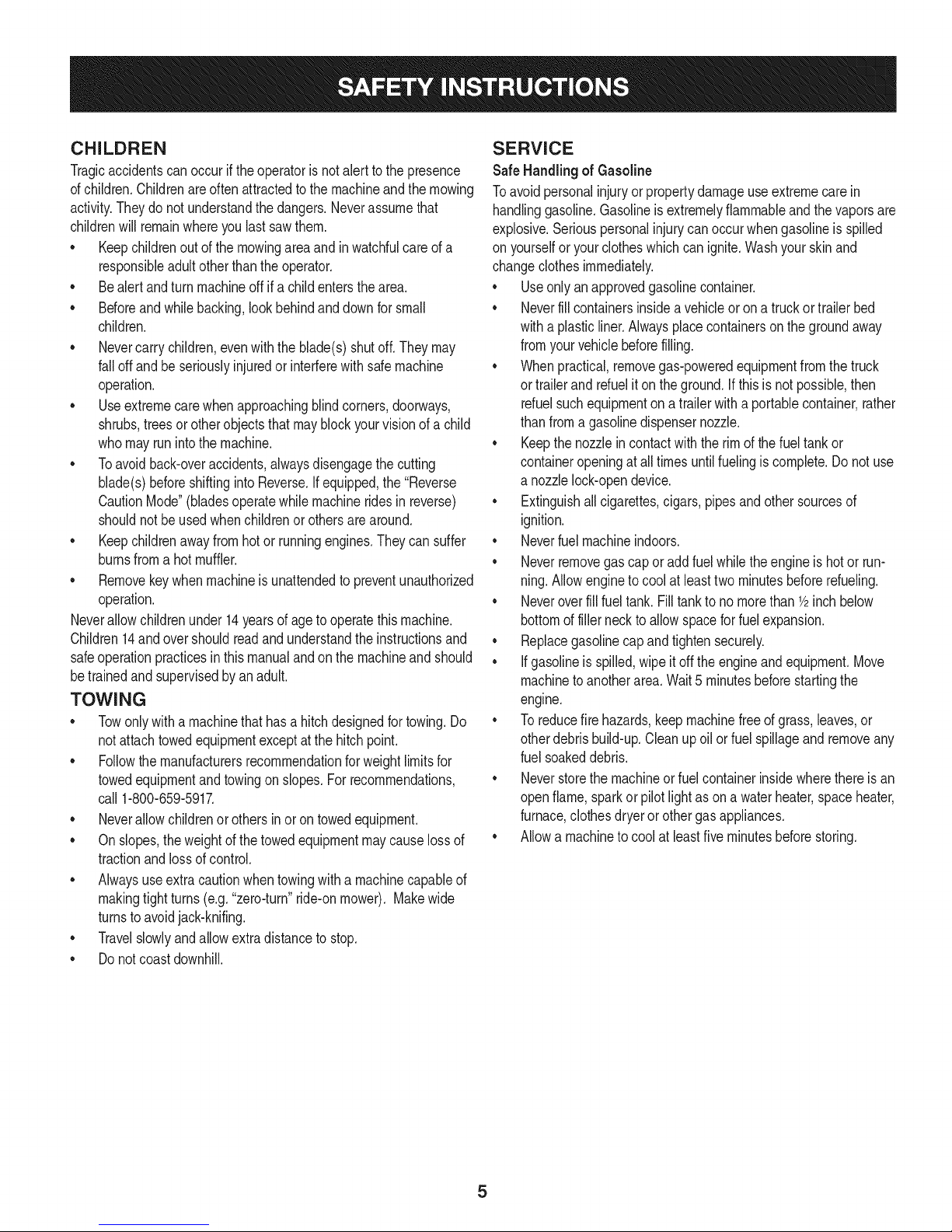
CHILDREN
Tragicaccidentscanoccuriftheoperatorisnotalertto the presence
ofchildren.Childrenareoftenattractedtothe machineandthe mowing
activity.Theydo notunderstandthedangers.Neverassumethat
childrenwillremainwhereyoulastsawthem.
• Keepchildrenoutof the mowingareaand inwatchfulcareofa
responsibleadultotherthantheoperator.
• Bealert andturnmachineoff ifa childentersthearea.
• Beforeandwhilebacking,lookbehindanddownforsmall
children.
Nevercarrychildren,evenwiththeblade(s)shutoff.Theymay
falloffandbe seriouslyinjuredorinterferewithsafemachine
operation.
• Useextremecarewhenapproachingblindcorners,doorways,
shrubs,treesorotherobjectsthatmayblockyourvisionof a child
whomayrunintothe machine.
Toavoidback-overaccidents,alwaysdisengagethe cutting
blade(s)beforeshiftingintoReverse.Ifequipped,the"Reverse
CautionMode"(bladesoperatewhilemachineridesinreverse)
shouldnotbe usedwhenchildrenor othersarearound.
Keepchildrenawayfromhotor runningengines.Theycansuffer
burnsfroma hotmuffler.
• Removekeywhenmachineisunattendedto preventunauthorized
operation.
Neverallowchildrenunder14yearsofagetooperatethis machine.
Children14andovershouldreadandunderstandthe instructionsand
safeoperationpracticesinthismanualandon the machineandshould
betrainedandsupervisedbyan adult.
TOWING
Towonlywitha machinethathasahitchdesignedfortowing.Do
notattachtowedequipmentexceptatthe hitchpoint.
Followthemanufacturersrecommendationforweightlimitsfor
towedequipmentandtowingonslopes.For recommendations,
call1-800-659-5917.
Neverallowchildrenor othersinoron towedequipment.
Onslopes,theweightof thetowedequipmentmaycauselossof
tractionandlossof control.
Alwaysuseextracautionwhentowingwitha machinecapableof
makingtightturns(e.g."zero-turn"ride-onmower). Makewide
turnstoavoidjack-knifing.
Travelslowlyandallowextradistancetostop.
Donotcoastdownhill.
SERVICE
SafeHandlingof Gasoline
Toavoidpersonalinjuryorpropertydamageuseextremecarein
handlinggasoline.Gasolineisextremelyflammableandthevaporsare
explosive.Seriouspersonalinjurycanoccurwhengasolineisspilled
on yourselforyourclotheswhichcanignite.Washyourskinand
changeclothesimmediately.
• Useonlyanapprovedgasolinecontainer.
Neverfill containersinsidea vehicleoron a truckortrailerbed
witha plasticliner.Alwaysplacecontainerson thegroundaway
fromyourvehiclebeforefilling.
Whenpractical,removegas-poweredequipmentfromthe truck
or trailerandrefueliton theground.Ifthis isnotpossible,then
refuelsuchequipmentona trailerwitha portablecontainer,rather
thanfroma gasolinedispensernozzle.
Keepthenozzleincontactwiththe rim ofthefueltankor
containeropeningat all timesuntilfuelingiscomplete.Donot use
a nozzlelock-opendevice.
Extinguishall cigarettes,cigars,pipesandothersourcesof
ignition.
• Neverfuelmachineindoors.
Neverremovegascapor addfuelwhilethe engineishotor run-
ning.Allowengineto coolat leasttwominutesbeforerefueling.
Neveroverfillfueltank. Filltanktono morethan1/2inchbelow
bottomoffillernecktoallowspaceforfuelexpansion.
• Replacegasolinecapandtightensecurely.
• Ifgasolineisspilled,wipeitoff the engineandequipment.Move
machineto anotherarea.Wait5 minutesbeforestartingthe
engine.
• To reducefirehazards,keepmachinefreeofgrass,leaves,or
otherdebrisbuild-up.Cleanup oilor fuelspillageandremoveany
fuelsoakeddebris.
• Neverstorethemachineorfuelcontainerinsidewherethereisan
openflame,sparkor pilotlightasona waterheater,spaceheater,
furnace,clothesdryeror othergasappliances.
Allowa machineto coolatleastfiveminutesbeforestoring.
Page 6
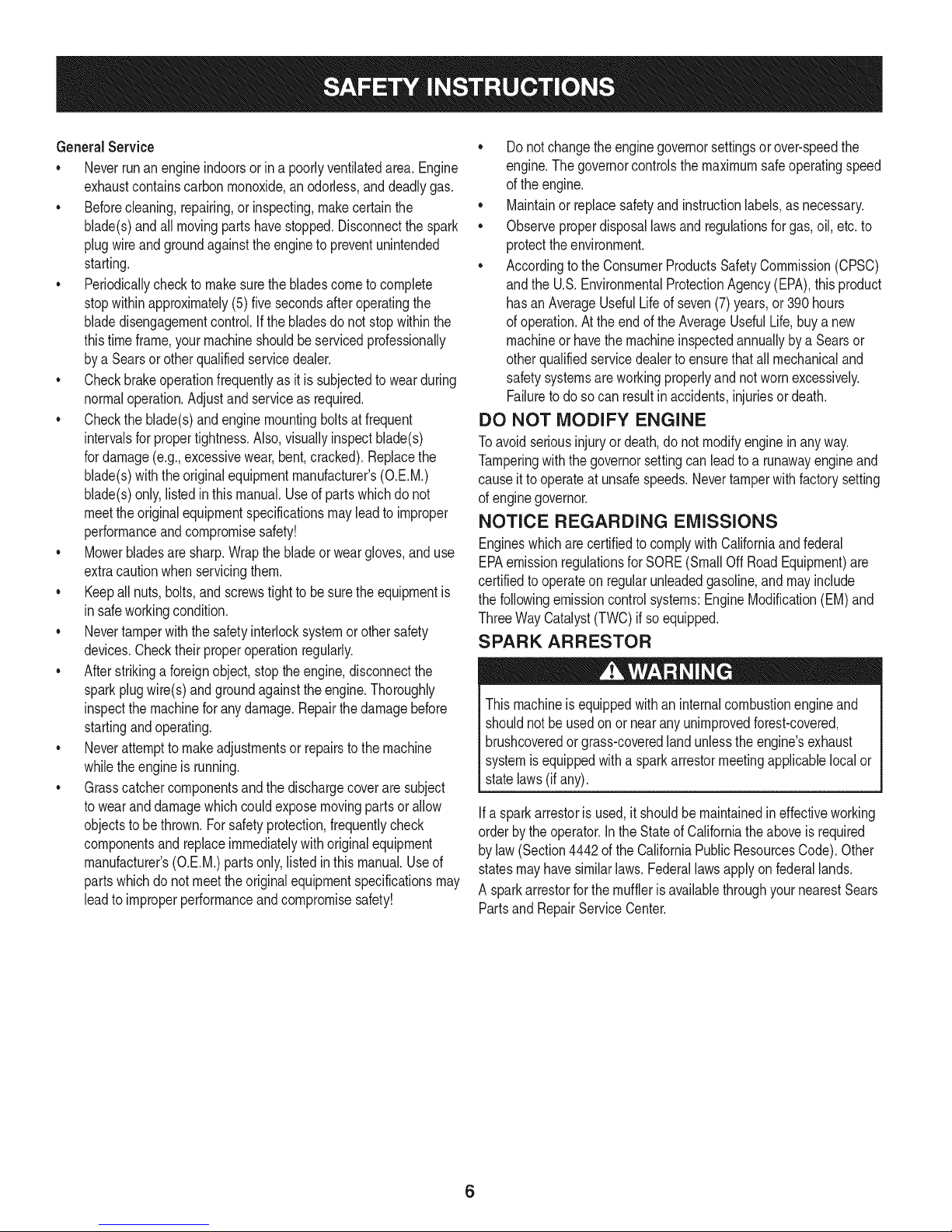
GeneralService
• Neverrunanengineindoorsorinapoorlyventilatedarea.Engine
exhaustcontainscarbonmonoxide,anodorless,anddeadlygas.
• Beforecleaning,repairing,orinspecting,makecertainthe
blade(s)andallmovingpartshavestopped.Disconnectthespark
plugwireandgroundagainsttheenginetopreventunintended
starting.
• Periodicallychecktomakesurethebladescometocomplete
stopwithinapproximately(5)fivesecondsafteroperatingthe
bladedisengagementcontrol.Ifthebladesdonotstopwithinthe
thistimeframe,yourmachineshouldbeservicedprofessionally
byaSearsorotherqualifiedservicedealer.
• Checkbrakeoperationfrequentlyasitissubjectedtowearduring
normaloperation.Adjustandserviceasrequired.
• Checktheblade(s)andenginemountingboltsatfrequent
intervalsforpropertightness.Also,visuallyinspectblade(s)
fordamage(e.g.,excessivewear,bent,cracked).Replacethe
blade(s)withtheoriginalequipmentmanufacturer's(O.E.M.)
blade(s)only,listedinthismanual.Useofpartswhichdonot
meettheoriginalequipmentspecificationsmayleadtoimproper
performanceandcompromisesafety!
• Mowerbladesaresharp.Wrapthebladeorweargloves,anduse
extracautionwhenservicingthem.
• Keepallnuts,bolts,andscrewstighttobesuretheequipmentis
insafeworkingcondition.
• Nevertamperwiththe safetyinterlocksystemorothersafety
devices.Checktheirproperoperationregularly.
• Afterstrikinga foreignobject,stopthe engine,disconnectthe
sparkplugwire(s)andgroundagainsttheengine.Thoroughly
inspectthemachineforanydamage.Repairthedamagebefore
startingandoperating.
• Neverattemptto makeadjustmentsor repairstothemachine
whilethe engineis running.
• Grasscatchercomponentsandthe dischargecoveraresubject
towearanddamagewhichcouldexposemovingpartsor allow
objectsto bethrown.Forsafetyprotection,frequentlycheck
componentsand replaceimmediatelywithoriginalequipment
manufacturer's(O.E.M.)partsonly,listedinthis manual.Useof
partswhichdo notmeettheoriginalequipmentspecificationsmay
leadtoimproperperformanceandcompromisesafety!
• Donotchangetheenginegovernorsettingsorover-speedthe
engine.Thegovernorcontrolsthe maximumsafeoperatingspeed
ofthe engine.
Maintainor replacesafetyandinstructionlabels,asnecessary.
• Observeproperdisposallawsandregulationsforgas,oil,etc.to
protecttheenvironment.
• Accordingtothe ConsumerProductsSafetyCommission(CPSC)
andthe U.S.EnvironmentalProtectionAgency(EPA),thisproduct
hasanAverageUsefulLifeofseven(7)years,or390hours
ofoperation.Attheendofthe AverageUsefulLife,buy anew
machineor havethemachineinspectedannuallybya Searsor
otherqualifiedservicedealerto ensurethatall mechanicaland
safetysystemsareworkingproperlyandnot wornexcessively.
Failuretodosocanresultinaccidents,injuriesor death.
DO NOT MODIFY ENGINE
Toavoid seriousinjuryor death,do notmodifyengineinanyway.
Tamperingwiththegovernorsettingcanleadtoa runawayengineand
causeittooperateat unsafespeeds.Nevertamperwithfactorysetting
ofenginegovernor.
NOTICE REGARDING EMISSIONS
Engineswhicharecertifiedto complywithCaliforniaandfederal
EPAemissionregulationsfor SORE(SmallOffRoadEquipment)are
certifiedto operateonregularunleadedgasoline,andmayinclude
thefollowingemissioncontrolsystems:EngineModification(EM)and
ThreeWayCatalyst(TWO)if soequipped.
SPARK ARRESTOR
Thismachineis equippedwithan internalcombustionengineand
shouldnotbe usedonor nearanyunimprovedforest-covered,
brushcoveredorgrass-coveredlandunlesstheengine'sexhaust
systemisequippedwitha sparkarrestormeetingapplicablelocalor
statelaws(if any).
Ifa sparkarrestoris used,it shouldbe maintainedin effectiveworking
orderbytheoperator.IntheStateof Californiatheaboveis required
bylaw (Section4442of the CaliforniaPublicResourcesCode).Other
statesmayhavesimilarlaws.Federallawsapplyonfederallands.
A sparkarrestorforthemuffleris availablethroughyournearestSears
PartsandRepairServiceCenter.
6
Page 7
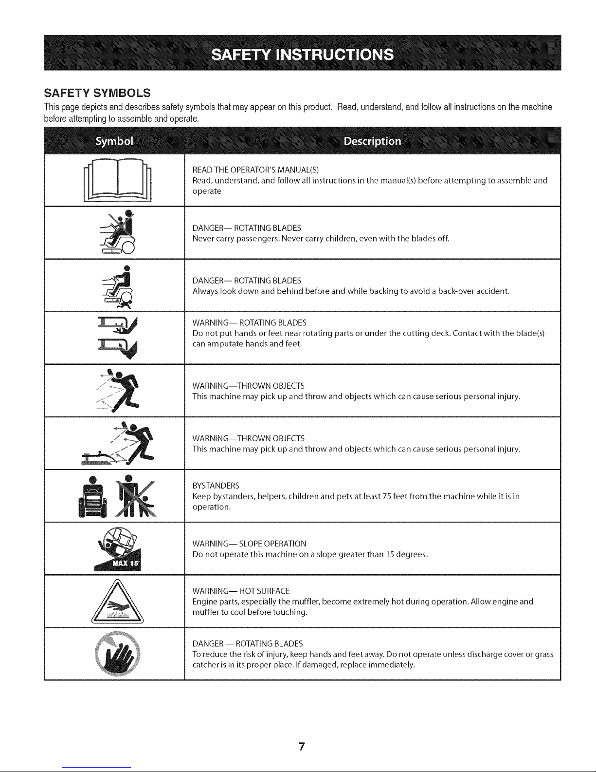
SAFETY SYMBOLS
Thispagedepictsanddescribessafetysymbolsthatmayappearonthis product. Read,understand,andfollowallinstructionson the machine
beforeattemptingtoassembleandoperate.
READ THE OPERATOR'S MANUAL(S)
Read, understand, and follow all instructions in the manual(s) before attempting to assemble and
operate
DANGER-- ROTATING BLADES
Never carry passengers. Never carry children, even with the blades off.
O
DANGER-- ROTATING BLADES
Always look down and behind before and while backing to avoid a back-over accident.
WARNING-- ROTATING BLADES
Do not put hands or feet near rotating parts or under the cutting deck. Contact with the blade(s)
can amputate hands and feet.
A
WARNING--THROWN OBJECTS
This machine may pick up and throw and objects which can cause serious personal injury.
WARNING--THROWN OBJECTS
This machine may pick up and throw and objects which can cause serious personal injury.
BYSTANDERS
Keep bystanders, helpers, children and pets at least 75 feet from the machine while it is in
operation.
WARNING-- SLOPE OPERATION
Do not operate this machine on a slope greater than 15 degrees.
WARNING-- HOT SURFACE
Engine parts, especially the muffler, become extremely hot during operation. Allow engine and
muffler to cool before touching.
DANGER- ROTATING BLADES
To reduce the risk of injury, keep hands and feet away. Do not operate unless discharge cover or grass
catcher is in its proper place. If damaged, replace immediately.
7
Page 8
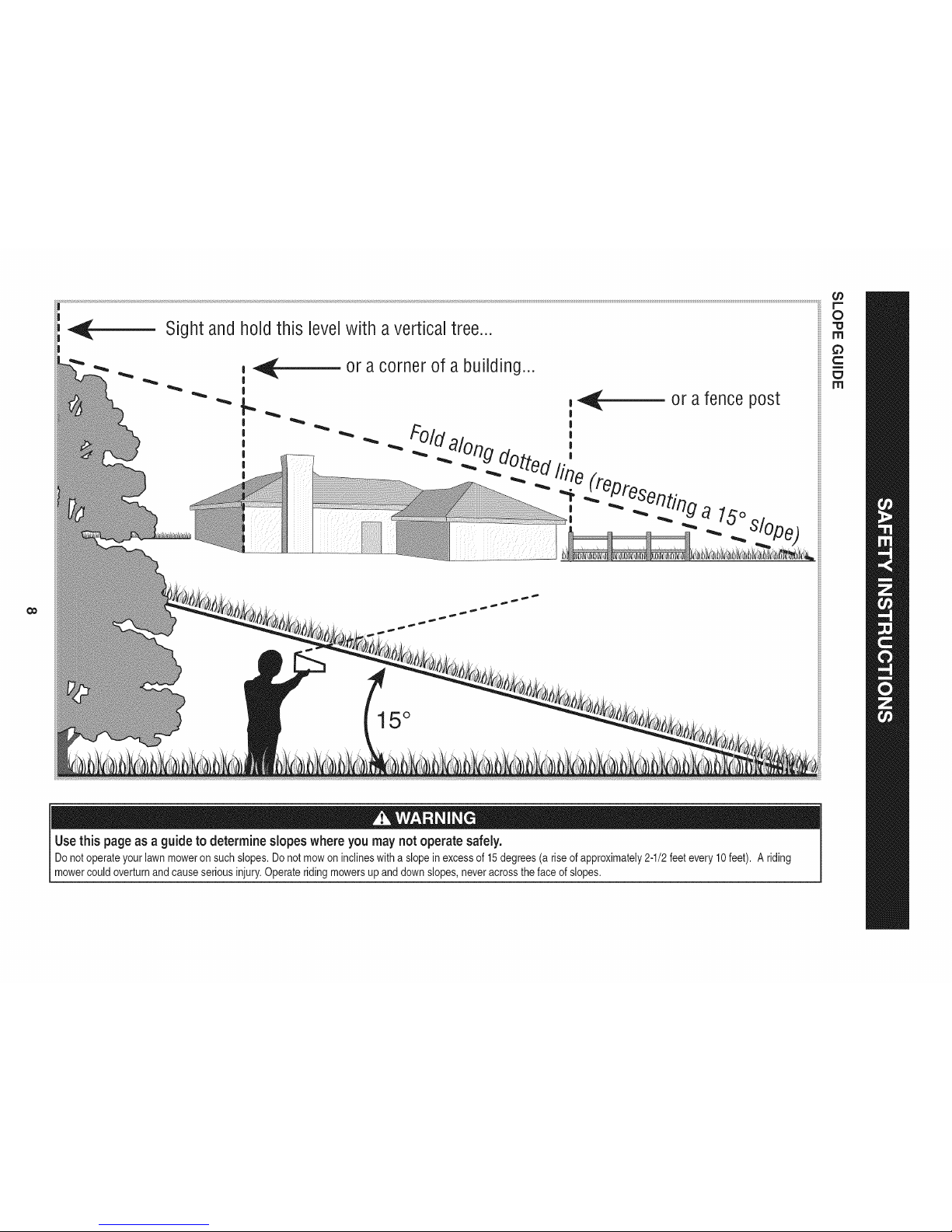
Sight and hold this levelwith avertical tree...
or a corner of a building...
or a fence post
II "_""_ _ . a 15o,,,
15°
0
rrl
rrl
Use this page as a guideto determine slopes where you may not operate safely.
Donot operateyourlawnmoweron suchslopes.Donotmowon inclineswitha slope inexcessof 15degrees(ariseof approximately2ol/2feetevery10feet). A riding
mowercouldoverturnandcauseseriousinjury.Operateridingmowersupanddownslopes,neveracrossthefaceofslopes.
Page 9
ROTATING BLADES CAUSE
_HEN CHI_REHOROTHERSARE
AROUND I •
_HILDREN EVENWITHBLADE(S)OFF.J
_HIND BEFOREANDWHILE J
BACKING. I
_RSE ISNOTRECOMMENDED, I
1. DISENGAGE BLADES/PTO, (POWER TAKE OFF)
2. ENGAGE THE TRACTOR'S PARKING BRAKE.
3. ACTIVATE THROTTLE TO RUN SETTING,
(MAN. SETTING NOT RECOMMENDED).
4. TURN KEY TO START ENGINE, AFTER START RELEASE KEY.
YOU MUST DISENGAGE SLADES/PTO, (FO_ TAKEOFF)
BEFORE TRAVELING IN REVERSE.
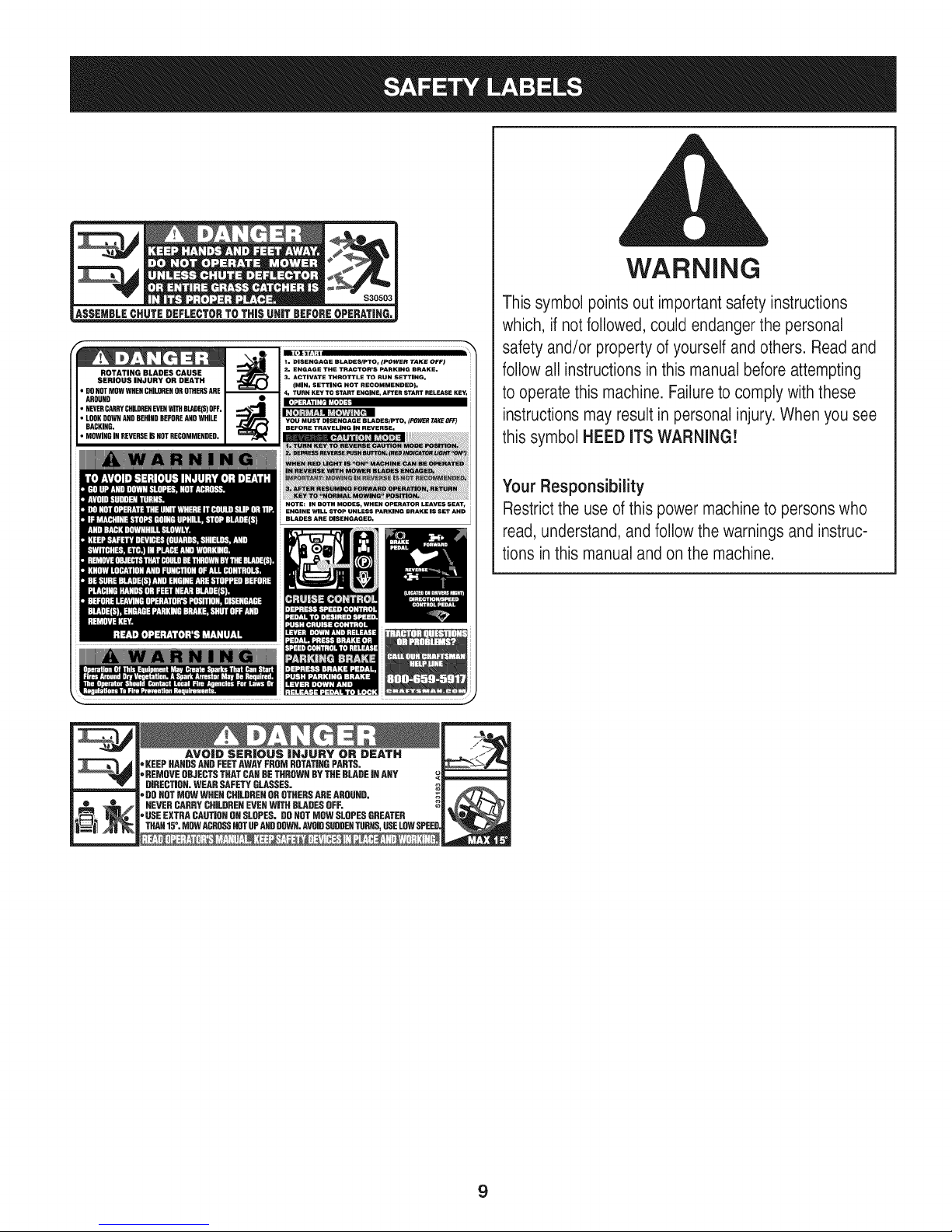
WARNING
Thissymbol points out importantsafety instructions
which, if not followed,could endangerthe personal
safety and/or property ofyourselfand others. Readand
followall instructionsin this manualbeforeattempting
to operatethis machine. Failureto comply with these
instructionsmay result in personalinjury.Whenyou see
this symbol HEED ITS WARNING!
Your Responsibility
Restrictthe use of this power machineto personswho
read, understand,and followthe warnings and instruc-
tions inthis manualand on the machine.
AVO|D SER|OUS |HJURY OR DEATH
"KEEPHANDSAHDFEETAWAYFROMROTATIRGPARTS.
'=REMOVEOBJECTSTHATCARDETHROWNBYTHEBLADEJRANY
DIRECTIOR.WEARSAFETYGLASSES.
'=DOROTMOWWHENCHILDRENOROTHERSAREAROUND,
NEVERCARRYCHILDRENEVERWITHBLADESOFF.
"USEEXTRACAUTIORONSLOPES.DOROTMOWSLOPESGREATER
THAH15°.MOWACROSSHOTUPANDDDWR.AVOIDSUDDERTURNS,USELOWSPEE
m
m
9
Page 10

TRACTOR SET-UP
Moving The Tractor Manually
Yourtractor'stransmissionisequippedwitha hydrostaticreliefvalve
foroccasionswhenitis necessaryto movethetractormanually.Open-
ingthisvalvepermitsthefluidin thetransmissionto bypassitsnormal
route,allowingthereartiresto "freewheel."Toopenthehydrostatic
reliefvalve,proceedasfollows:
1. Locatethehydrostaticbypassrodintherearof thetractor.See
Figure1.
Shipping Brace Removal
Makesurethe gardentractor'sengineisoff,settheparkingbrake
and removetheignitionkeybeforeremovingthe shippingbrace.
1. Locatetheshippingbrace,ifpresent,andwarningtagfoundon
the rightside ofthe cutting deck. See Figure 2.
f _
,\
Figure1
2. Pullthehydrostaticbypassrodoutward,thenup,to lock itin
place.
NOTE:The transmissionwillNOTengagewhenthehydrostatic
bypassrodis pulledout. Returnthe rodto itsnormalpositionpriorto
operatingthetractor.
Neverattemptto movethetractormanuallywithoutfirstopeningthe
hydrostaticreliefvalve.Doingsowillresultinseriousdamagetothe
tractor'stransmission.
Figure2
2. Whileholdingthedischargecoverchutedeflectorwithyourleft
hand,removetheshippingbracewithyourrighthandbygrasping
it betweenyourthumbandindexfingerandrotatingit clockwise.
Theshippingbraceis usedforpackagingpurposesonly.Removeant
discardtheshippingbracebeforeoperatingyourgardentractor.
Themowingdeckis capableofthrowingobjects.Operatingthe riding
mowerwithoutthedischargecoverin theproperoperatingposition
couldresultin seriouspersonalinjuryand/orpropertydamage.
10
Page 11
Connecting the Battery Cables Checking Tire Pressure
Batteryposts,terminals,andrelatedaccessoriescontainleadand
leadcompounds,chemicalsknowntotheStateofCaliforniatocause
cancerandreproductiveharm.Washhandsafterhandling.
Whenattachingbatterycables,alwaysconnectthe POSiTiVE(Red)
wireto its terminalfirst,followedbythe NEGATIVE(Black)wire.
Forshippingreasons,bothbatterycablesonyourequipmentmay
havebeenleft disconnectedfromtheterminalsatthefactory.To
connectthebatterycables,proceedasfollows:
NOTE:The positivebatteryterminalismarkedPos.(+).The negative
batteryterminalis markedNeg.(-).
NOTE:Ifthepositivebatterycableisalreadyattached,skipaheadto
step2.
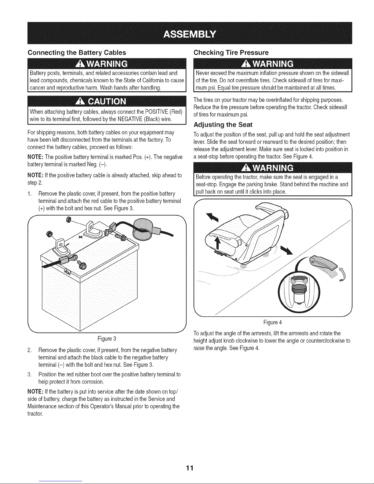
1. Removetheplasticcover,if present,fromthepositivebattery
terminalandattachthe redcabletothepositivebatteryterminal
(+)withthebolt andhexnut.See Figure3.
f
.\
Neverexceedthe maximuminflationpressureshownonthesidewall
ofthe tire.Do notoverinfiatetires.Checksidewalloftiresformaxi-
mumpsi.Equaltirepressureshouldbemaintainedatall times.
Thetiresonyourtractormaybeoverinfiatedforshippingpurposes.
Reducethe tirepressurebeforeoperatingthetractor.Checksidewall
oftiresformaximumpsi.
Adjusting the Seat
Toadjustthe positionoftheseat,pullupandholdtheseatadjustment
lever.Slidethe seatforwardor rearwardtothedesiredposition;then
releasetheadjustmentlever.Makesureseatis lockedintopositionin
a seat-stopbeforeoperatingthe tractor.SeeFigure4.
Beforeoperatingthetractor,makesurethe seatis engagedina
seat-stop.Engagetheparkingbrake.Standbehindthe machineand
pull backon seatuntil it clicksintoplace.
Figure3
2. Removetheplasticcover,if present,fromthenegativebattery
terminalandattachtheblackcableto the negativebattery
terminal(-) withthebolt andhexnut.SeeFigure3.
3. Positionthe redrubberbootoverthepositivebatteryterminalto
helpprotectit fromcorrosion.
NOTE:Ifthebatteryisputintoserviceafterthedateshownontop/
sided battery,chargethebatteryasinstructedintheServiceand
Maintenancesectionofthis Operator'sManualpriortooperatingthe
tractor.
Figure4
Toadjustthe angleofthearmrests,liftthe armrestsandrotatethe
heightadjustknobclockwisetolowertheangleor counterclockwiseto
raisetheangle.SeeFigure4.
11
Page 12
Setting the Deck Gauge Wheels and Roller
Movethetractoron a firmandlevelsurface,preferablypavement,and
proceedasfollows
1. Selecttheheightpositionof thecuttingdeckbyplacingthedeck
lift leverinthenormallydesiredmowingheightsetting(anyof the
elevendifferentcuttingheightnotcheson therightfender).
2. Checkthegaugewheelsforcontactorexcessiveclearancewith
thesurfacebelow.Thedeckgaugewheelsshouldhavebetween
l_-inchandY2-inchclearanceabovetheground.
Ifthegaugewheelshaveexcessiveclearanceorcontactwiththe
surface,adjustas follows:
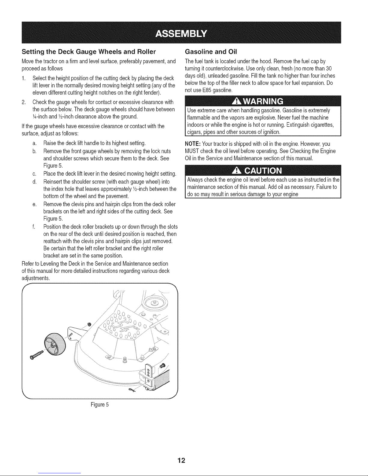
a. Raisethedecklift handletoitshighestsetting.
b. Removethefrontgaugewheelsbyremovingthelocknuts
andshoulderscrewswhichsecurethemto thedeck.See
Figure5.
c. Placethedecklift leverinthedesiredmowingheightsetting.
d. Reinserttheshoulderscrew(witheachgaugewheel)into
theindexholethatleavesapproximatelyY2-inchbetweenthe
bottomofthewheelandthepavement.
e. Removetheclevispins andhairpinclipsfromthedeck roller
bracketson theleftandrightsidesofthe cuttingdeck.See
Figure5.
f. Positionthedeck rollerbracketsupordownthroughtheslots
ontherearofthe deckuntildesiredpositionisreached,then
reattachwiththe clevispinsand hairpinclipsjust removed.
Becertainthatthe leftrollerbracketandtherightroller
bracketareset inthesameposition.
RefertoLevelingtheDeckintheServiceand Maintenancesection
ofthismanualfor moredetailedinstructionsregardingvariousdeck
adjustments.
f
Gasoline and Oil
Thefueltank islocatedunderthehood.Removethefuelcapby
turningit counterclockwise.Useonlyclean,fresh(no morethan30
daysold),unleadedgasoline.Fillthetanknohigherthanfourinches
belowthe topofthefiller necktoallowspaceforfuel expansion.Do
notuse E85gasoline.
Useextremecarewhenhandlinggasoline.Gasolineisextremely
flammableandthevaporsare explosive.Neverfuelthe machine
indoorsorwhiletheengineishotor running.Extinguishcigarettes,
cigars,pipesandothersourcesof ignition.
NOTE:Yourtractorisshippedwithoil inthe engine.However,you
MUSTchecktheoillevelbeforeoperating.SeeCheckingthe Engine
Oil inthe Serviceand Maintenancesectionofthismanual.
Alwayschecktheengineoil levelbeforeeachuseasinstructedin the
maintenancesectionofthis manual.Addoil asnecessary.Failureto
do somayresultin seriousdamagetoyourengine
Figure5
12
Page 13
f
SystemsIndicator
Monitor
FuelTank Cap
Throttle
I
FuelLevelIndicator
BrakePedal
SeatAdjustmentLever
Cup Holder"
ParkingBrake/
Cruise Control Lever
ignition Switch
Module
PTO(Blade
Knob
DrivePedal
Pedal
Lift Lever
\
Figure6
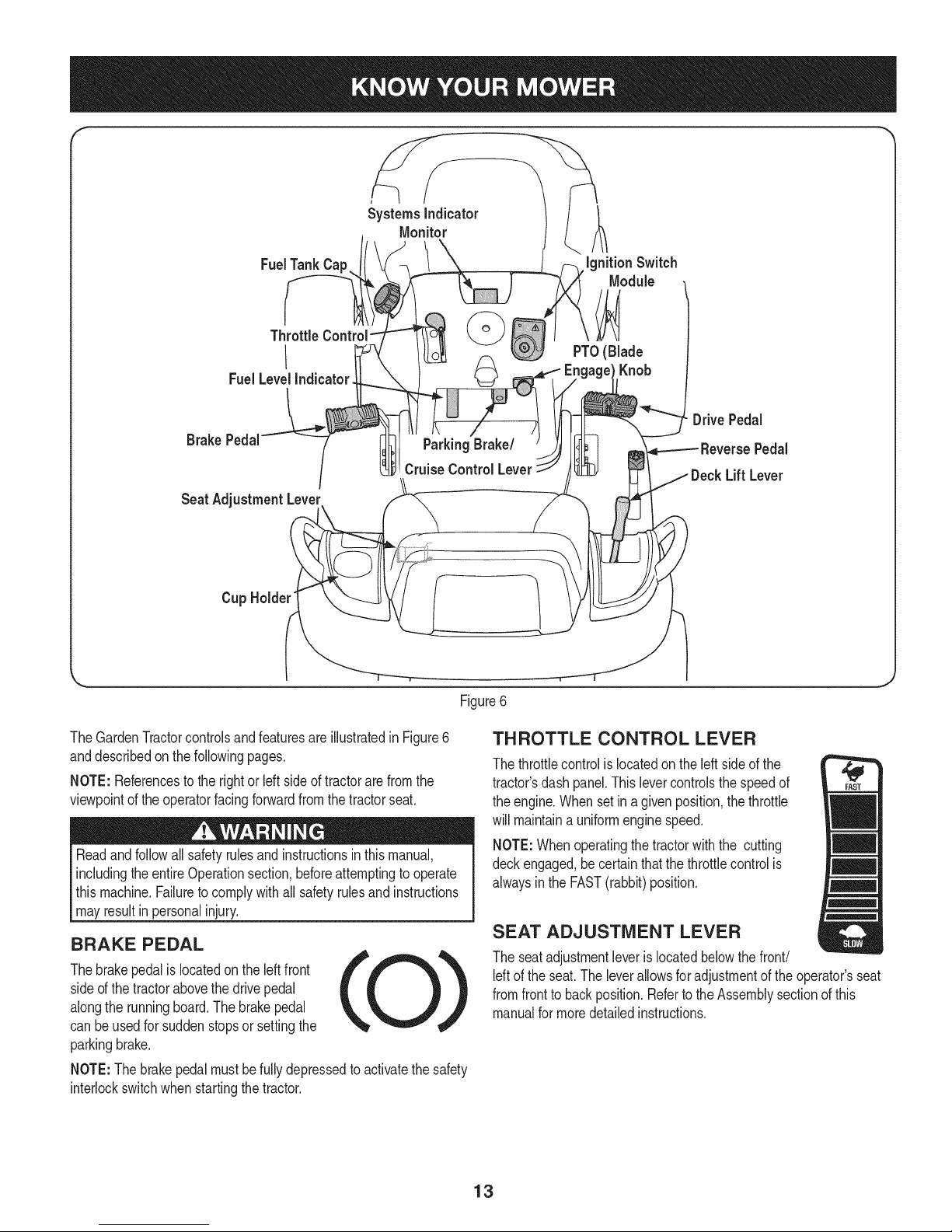
TheGardenTractorcontrolsandfeaturesareillustratedinFigure6
anddescribedon thefollowingpages.
NOTE:Referencestotherightor Idt sideof tractorarefromthe
viewpointoftheoperatorfacingforwardfromthetractorseat.
Readandfollowallsafetyrulesandinstructionsinthismanual,
includingtheentireOperationsection,beforeattemptingtooperate
this machine.Failuretocomplywithall safetyrulesand instructions
mayresultin personalinjury.
BRAKE PEDAL
Thebrakepedalislocatedontheleftfront
sideof thetractorabovethedrivepedal
alongthe runningboard.Thebrakepedal
canbeusedforsuddenstopsor settingthe
parkingbrake.
NOTE:The brakepedalmustbefullydepressedto activatethesafety
interlockswitchwhenstartingthetractor.
THROTTLE CONTROL LEVER
Thethrottlecontrolislocatedontheleft sideofthe
tractor'sdashpanel.Thislevercontrolsthespeedof
theengine.Whensetina givenposition,thethrottle
willmaintaina uniformenginespeed.
NOTE:Whenoperatingthetractorwiththe cutting
deckengaged,becertainthatthethrottlecontrolis
alwaysinthe FAST(rabbit)position.
SEAT ADJUSTMENT LEVER
Theseatadjustmentleveris locatedbelowthefront/
Idt of the seat.Theleverallowsforadjustmentoftheoperator'sseat
fromfronttobackposition.RefertotheAssemblysectionofthis
manualformoredetailedinstructions.
13
Page 14
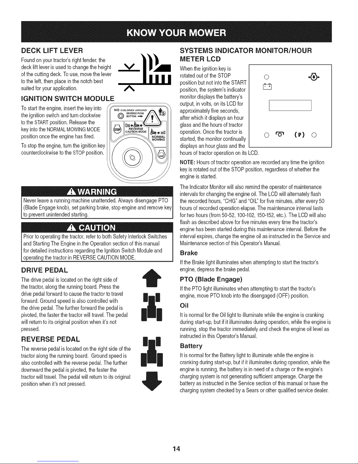
DECK LiFT LEVER
Foundonyourtractor'srightfender,the
decklift leverisusedtochangetheheight
ofthe cuttingdeck.Touse,movethelever
tothe left,thenplaceinthenotchbest
suitedforyourapplication.
IGNITION SWITCH MODULE
Tostart theengine,insertthekeyinto
theignitionswitchandturnclockwise
tothe STARTposition.Releasethe
keyintotheNORMALMOWINGMODE
positiononcethe enginehasfired.
Tostoptheengine,turntheignitionkey
counterclockwisetotheSTOPposition.
(BladeEngageknob),setparkingbrake,stopengineand remove
topreventunintendedstarting.
Priortooperatingthetractor,referto bothSafetyInterlockSwitches
andStartingTheEngineintheOperationsectionofthismanual
fordetailedinstructionsregardingthe IgnitionSwitchModuleand
[operatngthetractor n REVERSECAUTONMODE.
DRIVE PEDAL
Thedrivepedalislocatedon therightsideof
thetractor,alongthe runningboard.Pressthe
drivepedalforwardto causethetractortotravel
forward.Groundspeedisalsocontrolledwith
thedrive pedal.Thefurtherforwardthepedalis
pivoted,thefasterthetractorwilltravel.Thepedal
willreturnto itsoriginalpositionwhenit'snot
pressed.
REVERSE PEDAL
Thereversepedalis locatedonthe rightsideof the
tractoralongthe runningboard. Groundspeedis
alsocontrolledwiththe reversepedal.Thefurther
downwardthe pedalis pivoted,thefasterthe
tractorwilltravel.Thepedalwillreturnto itsoriginal
positionwhenit'snotpressed.
|
SYSTEMS INDICATOR MONITOR/HOUR
METER LCD
Whenthe ignitionkeyis
rotatedout oftheSTOP
positionbutnot intotheSTART
position,thesystem'sindicator
monitordisplaysthebattery's
output,in volts,on its LCDfor
approximatelyfiveseconds,
afterwhichitdisplaysanhour
glassandthehoursof tractor
operation.Oncethetractoris
started,themonitorcontinually
displaysanhourglassandthe
hoursof tractoroperationonitsLCD.
NOTE:Hoursof tractoroperationarerecordedanytimethe ignition
keyis rotatedoutof theSTOPposition,regardlessof whetherthe
engineisstarted.
TheIndicatorMonitorwillalso remindtheoperatorofmaintenance
intervalsforchangingtheengineoil.TheLCDwill alternatelyflash
the recordedhours,"CHG"and"OIL."forfiveminutes,afterevery50
hoursof recordedoperationelapse.Themaintenanceintervallasts
fortwo hours(from50-52,100-102,150-152,etc.).TheLCDwillalso
flashasdescribedaboveforfiveminuteseverytimethe tractor's
enginehasbeenstartedduringthismaintenanceinterval.Beforethe
intervalexpires,changetheengineoilas instructedinthe Serviceand
Maintenancesectionof thisOperator'sManual.
Brake
ifthe Brakelightilluminateswhenattemptingtostartthetractor's
engine,depressthebrakepedal.
PTO (Blade Engage)
IfthePTOlight illuminateswhenattemptingto startthetractor's
engine,movePTOknobinto thedisengaged(OFF)position.
Oil
Itis normalfortheOillightto illuminatewhiletheengineiscranking
duringstart-up,but if it illuminatesduringoperation,whiletheengineis
running,stopthetractorimmediatelyandchecktheengineoil levelas
instructedinthis Operator'sManual.
Battery
Itis normalfortheBatterylighttoilluminatewhiletheengineis
crankingduringstart-up,butif it illuminatesduringoperation,whilethe
engineisrunning,thebatteryis inneedof a chargeortheengine's
chargingsystemisnotgeneratingsufficientamperage.Chargethe
batteryas instructedin theServicesectionof thismanualor havethe
chargingsystemcheckedbyaSearsor otherqualifiedservicedealer.
0
I
o (r) o
14
Page 15

PTO / BLADE ENGAGE KNOB
Activatingthe PTOengagespowerto thecutting
deckorother(separatelyavailable)attachments.
Pulloutwardon thePTO/BladeEngageknobto
activateit.Pushthe PTO/Blade Engageknob
inwardtodisengagethepowertothecutting
deckorother(separatelyavailable)attachments.
NOTE:The PTO/BladeEngageknobmustbe in
thedisengaged(OFF)positionwhenstartingthe
engine.
PTO
OFF ON
PARKING BRAKE/CRUISE CONTROL LEVER
Locatedinthecenterof the tractor'sdashpanelbelow
thesteeringwheel,the ParkingBrake/CruiseControl
leveris usedtoengagethe parkingbrakeandthecruise
control.Refertothe Operationsectionof thismanualfor
detailedinstructionsregardingtheparkingbrake.
NOTE:The parkingbrakemustbesetiftheoperator
leavestheseatwiththe enginerunningorthe engine
willautomaticallyshutoff.
NOTE:Cruisecontrolcan NOTbeengagedatthe
tractor'sfastestgroundspeed.If theoperatorshould
attempttodo so,thetractorwill automaticallydecelerate
tothe fastestoptimalmowinggroundspeed.
FUEL LEVEL INDICATOR
TheFuelLevelIndicatorislocatedonthe left sideof thetractor's
dashand indicatestheamountoffuelinthe gas tank.
Neverleavea runningmachineunattended.AlwaysdisengagePTO
(BladeEngageknob),setparkingbrake,stopengineandremovekey
to preventunintendedstarting.
15
Page 16
SAFETY iNTERLOCK SWITCH ES
Thistractoris equippedwitha safetyinterlocksystemfortheprotection
ofthe operator.Iftheinterlocksystemshouldevermalfunction,do not
operatethetractor.Contacta Searsorotherqualifiedservicedealer.
• The safetyinterlocksystempreventstheenginefromcrankingor
startingunlessthe parkingbrakeisengaged,andthe PTO(Blade
Engage)knobis in thedisengaged(OFF)position.
Theenginewill automaticallyshutoffif theoperatorleavesthe
seatbeforeengagingtheparkingbrake.
• TheelectricPTO(BladeEngage)clutchwill automaticallyshut
off iftheoperatorleavesthetractor'sseatwiththe PTO(Blade
Engage)knobinthe engaged(ON)position,regardlessof
whetherthe parkingbrakeisengaged.
• Withthe ignitionkeyinthe NORMALMOWINGposition,the
electricPTO(BladeEngage)clutchwillautomaticallyshutoffif
thePTO(BladeEngage)knobis movedintotheengaged(ON)
positionwiththedrive pedalinpositionfor reversetravel.
Donotoperatethetractorifthe interlocksystemis malfunctioning.
Thissystemwasdesignedfor your safetyandprotection.
STARTING THE ENGINE
STOPPING THE ENGINE
Ifyoustrikeaforeignobject,stopthe engineanddisconnectthe
sparkplugwire(s).Thoroughlyinspectthemachineforanydamage.
Repairthedamagebeforerestartingandoperating.
1. Ifthebladesareengaged,placethe PTO/BladeEngageknobin
thedisengaged(OFF)position.
2. Placethethrottle/chokecontrolleverneartheSLOWposition.
3. Turnthe ignitionkeycounterclockwisetotheSTOPposition.
4. Removethe keyfromtheignitionswitchto preventunintended
starting.
DRIVING THE TRACTOR
Avoidsuddenstarts,excessivespeedandsuddenstops.
1. Lightlypressthebrakepedalto releasetheparkingbrake.Move
thethrottleleverintotheFAST(rabbit)position.
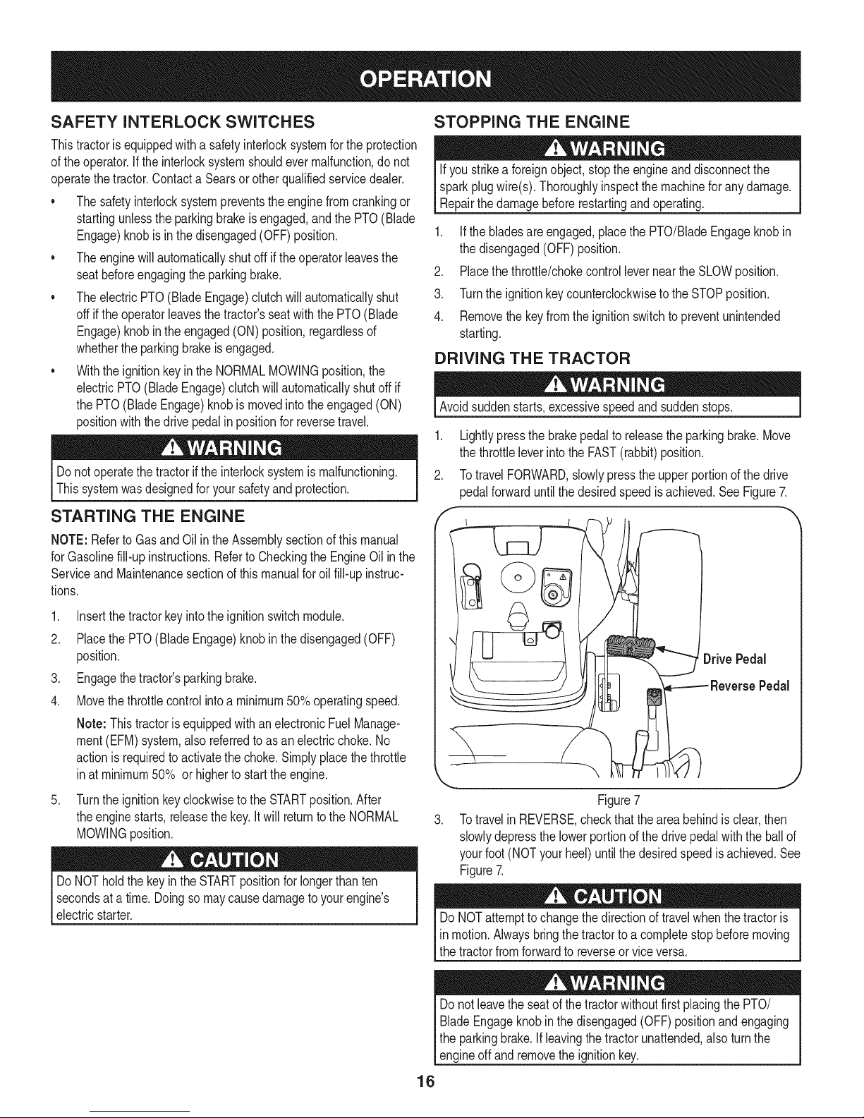
2. TotravelFORWARD,slowlypresstheupperportionofthedrive
pedalforwarduntilthe desiredspeedisachieved.SeeFigure7.
NOTE:Referto GasandOil inthe Assemblysectionofthismanual
forGasolinefill-upinstructions.RefertoCheckingthe EngineOil inthe
Serviceand Maintenancesectionofthis manualforoilfill-upinstruc-
tions.
1. Insertthe tractorkeyintothe ignitionswitchmodule.
2. Placethe PTO(BladeEngage)knobinthe disengaged(OFF)
position.
3. Engagethetractor'sparkingbrake.
4. Movethethrottlecontrolintoa minimum50%operatingspeed.
Note: ThistractorisequippedwithanelectronicFuelManage-
ment(EFM)system,also referredtoas anelectricchoke.No
actionisrequiredtoactivatethechoke.Simplyplacethethrottle
inat minimum50% orhigherto startthe engine.
.
Turntheignitionkeyclockwisetothe STARTposition.After
theenginestarts,releasethekey.Itwill returntotheNORMAL
MOWINGposition.
DoNOTholdthekeyintheSTARTpositionfor longerthanten
secondsata time.Doingso maycausedamagetoyourengine's
electricstarter.
,
Figure7
3. TotravelinREVERSE,checkthatthe areabehindis clear,then
slowlydepressthe lowerportionofthedrivepedalwiththeballof
yourfoot (NOTyourheel)untilthe desiredspeedisachieved.See
Figure7.
DoNOTattemptto changethedirectionoftravelwhenthetractoris
in motion.Alwaysbringthetractortoa completestopbeforemoving
thetractorfromforwardto reverseorviceversa.
Donot leavetheseatof thetractorwithoutfirstplacingthePTO/
BladeEngageknobinthe disengaged(OFF)positionandengaging
theparkingbrake.Ifleavingthetractorunattended,alsoturn the
engineoff andremovetheignitionkey.
16
Page 17
REVERSE CAUTION MODE
TheREVERSECAUTIONMODEpositionof thekeyswitchmodule
allowsthetractorto beoperatedinreversewiththe blades(PTO)
engaged.
NOTE:Mowinginreverseisnotrecommended.
Useextremecautionwhileoperatingthetractorin the REVERSE
CAUTIONMODE.Alwayslookdownandbehindbeforeandwhile
backing.Donotoperatethetractorwhenchildrenor othersare
around.Stopthetractorimmediatelyif someoneentersthearea.
Touse theREVERSECAUTIONMODE:
NOTE:The operatorMUSTbe seatedinthetractorseat.
1. Starttheengineaspreviouslyinstructedonthe previouspage.
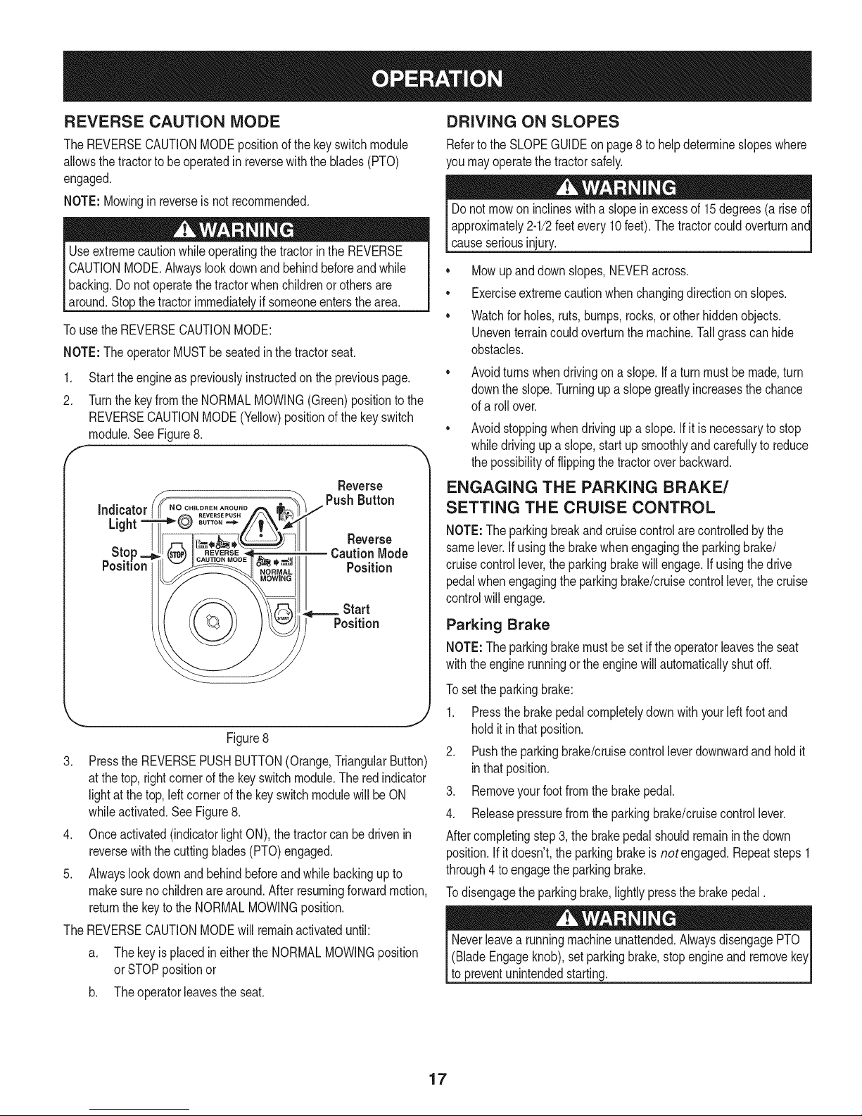
2. Turnthekeyfromthe NORMALMOWING(Green)positiontothe
REVERSECAUTIONMODE(Yellow)positionofthe keyswitch
module.SeeFigure8.
F "
Reverse
DRIVING ON SLOPES
Referto theSLOPEGUIDEon page8 tohelpdetermineslopeswhere
youmayoperatethetractorsafely.
Donot mowon inclineswitha slopeinexcessof 15degrees(a rise
approximately2-1/2feetevery10feet).The tractorcouldoverturnanc
causeseriousinjury.
• Mowupanddownslopes,NEVERacross.
• Exerciseextremecautionwhenchangingdirectiononslopes.
• Watchforholes,ruts,bumps,rocks,or otherhiddenobjects.
Uneventerraincouldoverturnthe machine.Tallgrasscanhide
obstacles.
Avoidturnswhendrivingona slope.If a turnmustbe made,turn
downthe slope.Turningupaslopegreatlyincreasesthechance
ofa rollover.
Avoidstoppingwhendrivingupa slope.If itisnecessaryto stop
whiledrivingup a slope,startupsmoothlyandcarefullyto reduce
thepossibilityof flippingthetractoroverbackward.
ENGAGING THE PARKING BRAKE/
SETTING THE CRUISE CONTROL
NOTE:Theparkingbreakandcruisecontrolarecontrolledbythe
samelever.Ifusingthe brakewhenengagingtheparkingbrake/
cruisecontrollever,theparkingbrakewillengage.Ifusingthedrive
pedalwhenengagingtheparkingbrake/cruisecontrollever,thecruise
controlwillengage.
Figure8
3. PresstheREVERSEPUSHBUTTON(Orange,TriangularButton)
atthe top,rightcornerof the keyswitchmodule.Theredindicator
lightat thetop,leftcornerofthe keyswitchmodulewillbe ON
whileactivated.SeeFigure8.
4. Onceactivated(indicatorlightON),thetractorcan bedrivenin
reversewiththe cuttingblades(PTO)engaged.
5. Alwayslookdownand behindbeforeandwhilebackingupto
makesureno childrenarearound.After resumingforwardmotion,
returnthe keytotheNORMALMOWINGposition.
TheREVERSECAUTIONMODEwill remainactivateduntil:
a. Thekeyisplacedin eithertheNORMALMOWINGposition
orSTOPpositionor
b. Theoperatorieavestheseat.
Parking Brake
NOTE:Theparkingbrakemustbesetif theoperatorleavestheseat
withtheenginerunningor theenginewillautomaticallyshutoff.
Tosettheparkingbrake:
1. Pressthebrakepedalcompletelydownwith yourleftfootand
holditinthat position.
2. Pushtheparkingbrake/cruisecontrolleverdownwardandholdit
inthatposition.
3. Removeyourfootfromthebrakepedal.
4. Releasepressurefromtheparkingbrake/cruisecontrollever.
Aftercompletingstep3,the brakepedalshouldremaininthedown
position.Ifitdoesn't,theparkingbrakeisnotengaged.Repeatsteps1
through4 toengagethe parkingbrake.
Todisengagetheparkingbrake,lightlypressthebrakepedal.
(BladeEngageknob),setparkingbrake,stopengineandremove
to preventunintendedstarting.
17
Page 18

Cruise Control MOWING
Neverengagethe cruisecontrolleverwhiletravelinginreverse.
Tosetthe cruisecontrol:
1. Slowlypresstheupperportionof thedrivepedalwithyour right
footuntilthe desiredspeedisachieved.
2. Lightlypresstheparkingbrake/cruisecontrolleverdownwardand
holditin thatposition.
3. Removeyourfootfromthedrivepedal.
4. Releasepressurefromtheparkingbrake/cruisecontrollever
Aftercompletingstep3, thedrivepedalshouldremaininthedown
positionandthetractorwillmaintainthe sameforwardspeed.If it
doesn't,thecruisecontrolis not engaged.Repeatsteps 1through4to
engagethecruisecontrol.
Todisengagethe cruisecontrol,lightlypressthedrivepedalor the
brakepedal.
NOTE:Cruisecontrolcannotbesetatthe tractor'sfastestground
speed.If theoperatorshouldattempttodo so,thetractorwillautomati-
callydecelerateto thefastestoptimalmowinggroundspeed.
Tochangethedirectionof travelfromforwardto reversewhencruise
controlisengaged,pressthebrakepedaltodisengagethecruise
controlandbringthetractortoa completestop.Thenslowlypressthe
reversepedalwiththeballofyourfoottotravelinreverse.
ENGAGING THE PTO
Engagingthe PTOtransferspowertothecuttingdeckor other
(separatelyavailable)attachments.Toengagethe PTO:
1. Movethethrottlecontrollevertothe FAST(rabbit)position.
2. PullthePTO/BladeEngageknoboutwardintotheengaged(ON)
position.SeeFigure9.
NOTE:Alwaysoperatethetractorwiththe throttleleverinthe FAST
(rabbit)positionforthemostefficientuseofthe cuttingdeckorother
(separatelyavailable)attachments.
Tohelpavoidbladecontactora thrownobjectinjury,keepbystand-
ers,helpers,childrenandpetsat least75feetfromthemachinewhile
it isin operation.Stopmachineif anyoneentersthearea.
Thefollowinginformationwillbehelpfulwhenusingthecuttingdeck
withyourtractor.
Planyourmowingpatternto avoiddischargeof materialstoward
roads,sidewalks,bystandersandthe like.Also,avoiddischarging
materialagainstawallorobstructionwhichmaycausedischarged
materialtoricochetbacktowardtheoperator.
• Donotmowat highgroundspeed,especiallyif a mulchkitor
grasscollectoris installed.
• Donotcutthegrasstooshort.Shortgrassis pronetoweed
growthandyellowsquicklyindryweather.
• AlwaysoperatethetractorwiththethrottleleverintheFAST
(rabbit)positionwhilemowing.
• Forbestresultsit isrecommendedthatthe firsttwolapsbecut
withthedischargethrowntowardsthecenter.Afterthefirsttwo
laps, reversethedirectionto throwthedischargeto theoutside
forthe balanceofcutting.Thiswill givea betterappearanceto the
lawn.
DoNOTattemptto mowheavybrushand weedsorextremelytall
grass.Yourtractorisdesignedtomowlawns,NOTclearbrush.
• Keepthebladessharpandreplacethebladeswhenworn.
USING THE DECK LIFT LEVER
Toraisethecuttingdeck,movethedeckliftleverto the left,thenplace
it inthenotchbestsuitedforyourapplication.
OPERATING THE HEADLIGHTS
ThelampsareONwhenevertheignitionkeyis rotatedoutoftheSTOP
position.ThelampsturnOFFwhentheignitionkeyis movedto the
STOPposition.
Figure9
OFF
J
18
Page 19
Beforeperforminganytypeofmaintenance/service,disengageall
controlsandstoptheengine.Waituntilallmovingpartshavecometo
acompletestop.Disconnectsparkplugwireandgrounditagainstthe
engineto preventunintendedstarting.Alwayswearsafetyglassesduring
operationorwhileperforminganyadjustmentsor repairs.
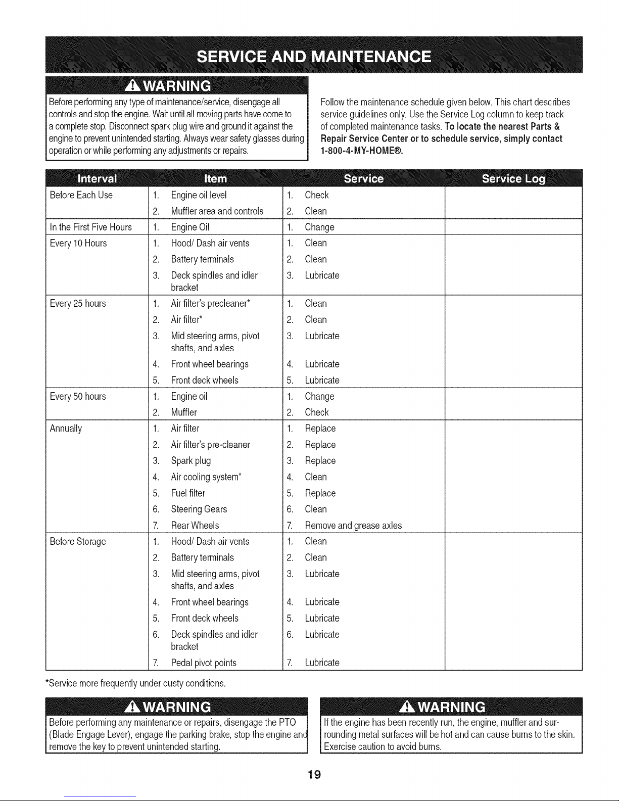
Followthe maintenanceschedulegivenbelow.Thischartdescribes
serviceguidelinesonly.Usethe ServiceLogcolumnto keeptrack
ofcompletedmaintenancetasks.Tolocate thenearest Parts&
RepairService Centeror to scheduleservice,simplycontact
1-800-4-MY-HOME®.
BeforeEachUse
Inthe First FiveHours
Every10Hours
Every25 hours
Every50 hours
Annually
BeforeStorage
1. Engineoillevel
2. Mufflerareaandcontrols
1. EngineOil
1. Hood/Dashair vents
2. Batteryterminals
3. Deckspindlesandidler
bracket
1. Airfilter'sprecleaner*
2. Airfilter*
3. Midsteeringarms,pivot
shafts,andaxles
4. Frontwheelbearings
5. Frontdeckwheels
1. Engineoil
2. Muffler
1. Airfilter
2. Airfilter'spre-cleaner
3. Sparkplug
4. Aircoolingsystem*
5. Fuelfilter
6. SteeringGears
7. RearWheels
1. Hood/Dashair vents
2. Batteryterminals
3. Midsteeringarms,pivot
shafts,andaxles
4. Frontwheelbearings
5. Frontdeckwheels
6. Deckspindlesandidler
bracket
7. Pedalpivotpoints
1. Check
2. Clean
1. Change
1. Clean
2. Clean
3. Lubricate
1. Clean
2. Clean
3. Lubricate
4. Lubricate
5. Lubricate
1. Change
2. Check
1. Replace
2. Replace
3. Replace
4. Clean
5. Replace
6. Clean
7. Removeandgreaseaxles
1. Clean
2. Clean
3. Lubricate
4. Lubricate
5. Lubricate
6. Lubricate
7. Lubricate
*Servicemorefrequentlyunderdustyconditions.
(BladeEngageLever),engagethe parkingbrake,stopthe engine
removethe keyto preventunintendedstarting.
If theenginehasbeenrecentlyrun,theengine,mufflerandsur-
roundingmetalsurfaceswill behotandcancauseburnstotheskin.
Exercisecautiontoavoidburns.
19
Page 20
NOTE:Referencesto therightor leftsideoftractorarefromthe
viewpointof theoperatorfacingforwardfromthetractorseat.
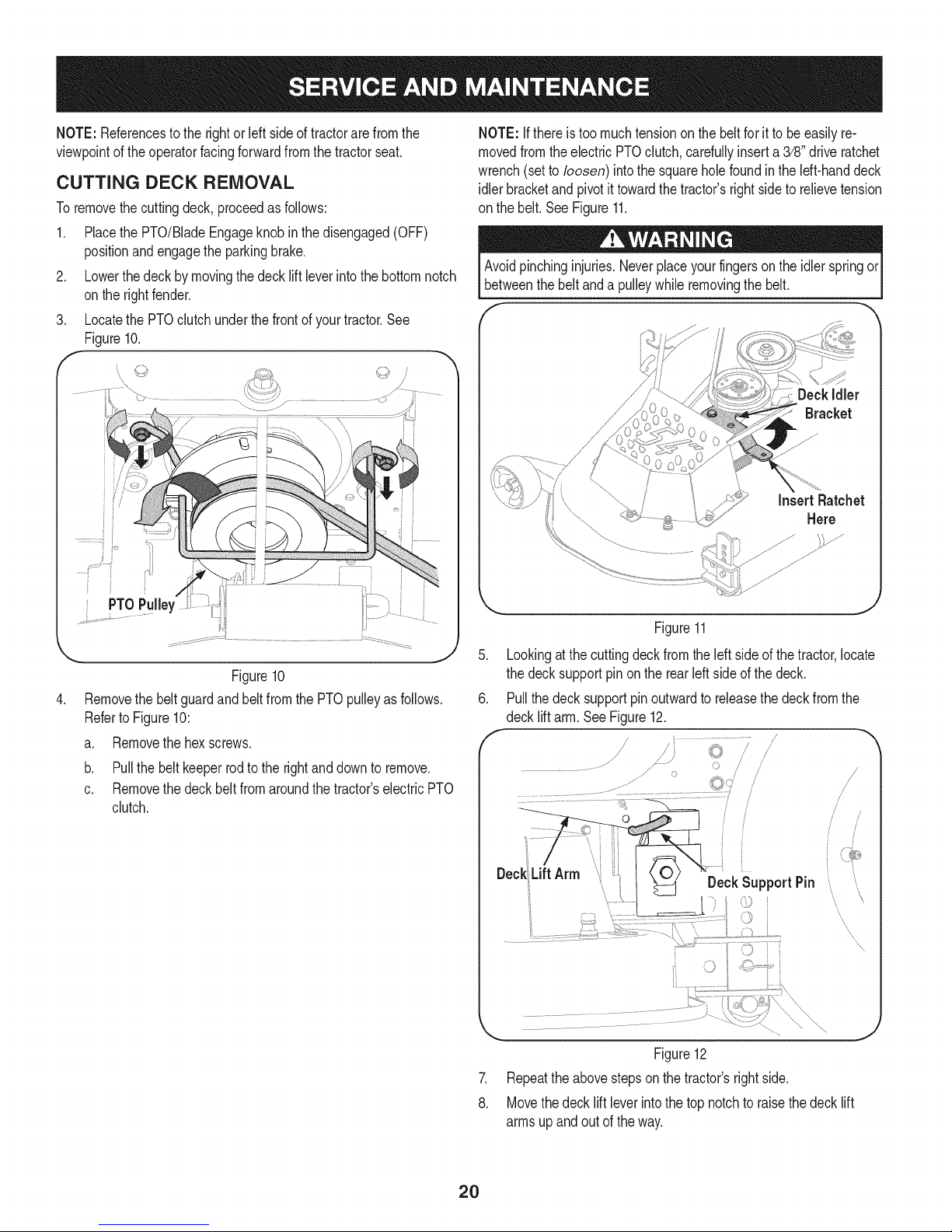
CUTTING DECK REMOVAL
Toremovethecuttingdeck, proceedasfollows:
1. Placethe PTO/BladeEngageknobinthedisengaged(OFF)
positionandengagetheparkingbrake.
2. Lowerthedeckbymovingthedeck liftleverintothebottomnotch
ontherightfender.
3. LocatethePTOclutchunderthefrontof yourtractor.See
Figure10.
f
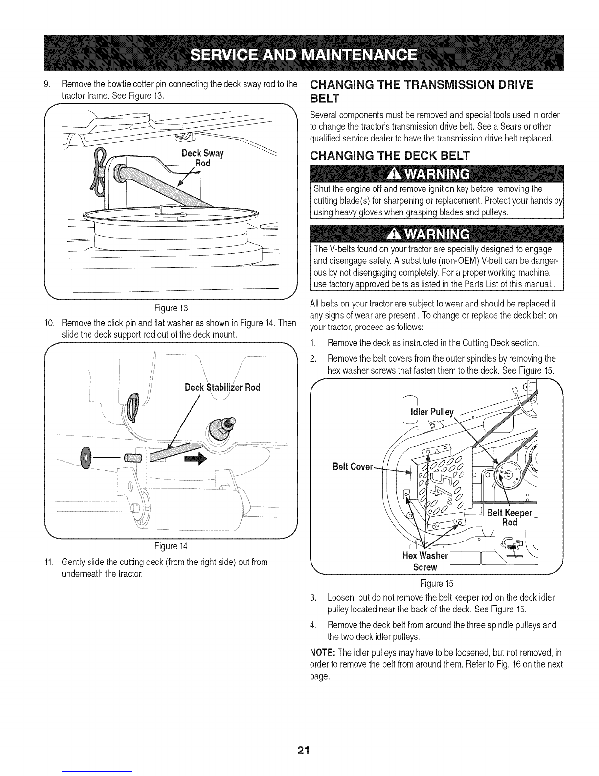
NOTE:Ifthereis toomuchtensionon thebeltforit tobe easilyre-
movedfromtheelectric PTOclutch,cardully inserta 3/8" driveratchet
wrench(setto loosen) intothesquareholefoundintheIdt-handdeck
idlerbracketandpivotittowardthe tractor'srightsideto relievetension
on thebelt.SeeFigure11.
Avoidpinchinginjuries.Neverplaceyourfingersonthe idlerspringor
betweenthebeltanda pulleywhileremovingthebelt.
DeckIdler
Bracket
InsertRatchet
Here
.
b. Pullthebeltkeeperrodtotherightanddownto remove.
c. Removethedeckbelt fromaroundthetractor'selectricPTO
clutch.
Figure11
.
Lookingatthecuttingdeckfromtheleftsideofthetractor,locate
thedecksupportpinon therearleftsideof thedeck.
6.
Pullthedecksupportpinoutwardto releasethedeckfromthe
f
DeckLiftArm
Figure12
.
Repeatthe abovestepsonthe tractor'srightside.
8.
Movethedecklift leverintothetopnotchto raisethedecklift
armsupandoutoftheway.
DeckSupportPin
/
J
/
i
i
'xx
'x
20
Page 21
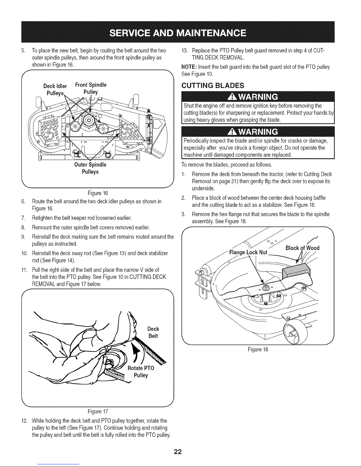
9. Removethebowtiecotterpinconnectingthedeckswayrodto the
tractorframe.SeeFigure13.
Rod
CHANGING THE TRANSMISSION DRIVE
BELT
Severalcomponentsmustbe removedand specialtoolsusedinorder
tochangethetractor'stransmissiondrivebelt.Seea Searsorother
qualifiedservicedealerto havethetransmissiondrivebeltreplaced.
CHANGING THE DECK BELT
Shutthe engineoff andremoveignitionkeybeforeremovingthe
cuttingblade(s)forsharpeningor replacement.Protectyourhands
usingheavygloveswhengraspingbladesand pulleys.
TheV-beltsfoundon yourtractorarespeciallydesignedtoengage
anddisengagesafely.A substitute(non-OEM)V-beltcan bedanger-
ousby notdisengagingcompletely.Fora properworkingmachine,
usefactoryapprovedbeltsas listedinthePartsListofthismanual..
Figure13
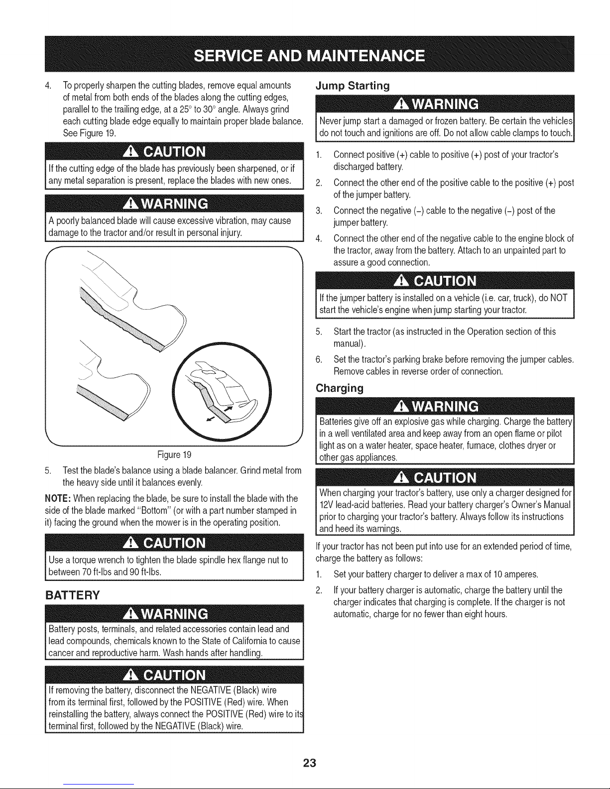
10. Removetheclickpinandflatwasherasshownin Figure14.Then
slidethe decksupportrodout ofthedeckmount.
, /
DeckNtabiliz_erRod
'\ /
...............................................................................i:':111"7
Figure14
11. Gentlyslidethe cuttingdeck(fromtherightside)outfrom
underneaththetractor.
All beltsonyourtractoraresubjectto wearandshouldbereplacedif
anysignsof wear arepresent.Tochangeor replacethe deck belton
yourtractor,proceedasfollows:
1. Removethedeckasinstructedinthe CuttingDecksection.
2. Removethe beltcoversfromtheouterspindlesby removingthe
hexwasherscrewsthatfastenthemtothedeck.SeeFigure15.
f
_ler
Belt KeeperZ
Rod
HexWasher [
Screw
.J
Figure15
3. Loosen,butdonotremovethe beltkeeperrodon thedeckidler
pulleylocatednearthe backofthedeck.SeeFigure15.
4. Removethe deckbeltfromaroundthethreespindlepulleysand
thetwodeckidlerpulleys.
NOTE:Theidlerpulleysmayhaveto beloosened,butnotremoved,in
ordertoremovethebeltfromaroundthem.RefertoFig.16onthenext
page.
21
Page 22
5. Toplacethenewbelt,beginbyroutingthebelt aroundthetwo
outerspindlepulleys,thenaroundthefront spindlepulleyas
shownin Figure16.
F
13. ReplacethePTOPulleybeltguardremovedinstep4 ofCUT-
TINGDECKREMOVAL.
NOTE:Insertthebeltguardintothe beltguardslotofthePTOpulley.
See Figure10.
Deckidler FrontSpindle
Pulley
OuterSpindle
Pulleys
Figure16
Routethebeltaroundthetwodeckidlerpulleysasshownin
Figure16.
Z
Retightenthebelt keeperrodloosenedearlier.
8.
Remounttheouterspindlebeltcoversremovedearlier.
9.
Reinstallthedeckmakingsurethe beltremainsroutedaroundthe
pulleysasinstructed.
10.
Reinstallthedeckswayrod(See Figure13)anddeckstabilizer
rod(SeeFigure14).
11.
Pulltherightside ofthe beltandplacethenarrowVside of
thebelt intothePTOpulley.SeeFigure10in CUTTINGDECK
REMOVALandFigure17below.
f
CUTTING BLADES
Shutthe engineoff andremoveignitionkeybeforeremovingthe
cuttingblade(s)forsharpeningor replacement.Protectyourhands
usingheavygloveswhengraspingthe blade.
Periodicallyinspectthebladeand/orspindlefor cracksordamage,
especiallyafter you'vestrucka foreignobject.Donotoperatethe
machineuntildamagedcomponentsare replaced.
Toremovetheblades,proceedasfollows.
1. Removethedeckfrombeneaththetractor,(referto CuttingDeck
J
Removalon page21)thengentlyflipthe deckovertoexposeits
underside.
2. Placea blockofwoodbetweenthecenterdeckhousingbaffle
andthecuttingbladeto actas a stabilizer.See Figure18.
3. Removethe hexflangenutthatsecuresthebladetothespindle
assembly.SeeFigure18.
e LockNut
Block
f
... J
Figure17
12. Whileholdingthe deckbeltand PTOpulleytogether,rotatethe
pulleyto theleft(SeeFigure17).Continueholdingandrotating
thepulleyand beltuntilthe beltisfully rolledintothePTOpulley.
Deck
Belt
Figure18
RotatePTO
Pulley
22
Page 23
Toproperlysharpenthecuttingblades,removeequalamounts
4. Jump Starting
ofmetalfrombothendsofthebladesalongthecuttingedges,
paralleltothetrailingedge,ata 250to300angle.Alwaysgrind
eachcuttingbladeedgeequallyto maintainproperbladebalance.
SeeFigure19.
Ifthecuttingedgeof thebladehaspreviouslybeensharpened,orif
anymetalseparationis present,replacethebladeswithnewones.
A poorlybalancedbladewillcauseexcessivevibration,maycause
damageto thetractorand/orresultinpersonalinjury.
f
\
Neverjump starta damagedor frozenbattery.Becertainthevehicles
do nottouchandignitionsareoff.Donot allowcableclampstotouch.
1. Connectpositive(+)cabletopositive(+) postof your tractor's
dischargedbattery.
2. Connectthe otherendofthe positivecableto thepositive(+)post
ofthe jumperbattery.
3. Connectthe negative(-) cabletothenegative(-) postof the
jumperbattery.
4. Connectthe otherendofthe negativecabletothe engineblockof
thetractor,awayfromthe battery.Attachtoanunpaintedpartto
assurea goodconnection.
Ifthejumperbatteryis installedona vehicle(i.e.car,truck),do NOT
startthe vehicle'senginewhenjumpstartingyourtractor.
5. Startthe tractor(asinstructedintheOperationsectionofthis
manual).
6. Setthetractor'sparkingbrakebeforeremovingthejumpercables.
Removecablesinreverseorderofconnection.
Figure19
5. Testtheblade'sbalanceusinga bladebalancer.Grindmetalfrom
theheavyside untilit balancesevenly.
NOTE:Whenreplacingtheblade,besureto installthebladewiththe
sided theblademarked"Bottom"(orwitha partnumberstampedin
it)facingthe groundwhenthemoweris in theoperatingposition.
Useatorquewrenchtotightenthebladespindlehexflangenutto
between70ft-lbs and90ft-lbs.
BATTERY
Batteryposts,terminals,andrelatedaccessoriescontainleadand
leadcompounds,chemicalsknowntotheStateofCaliforniatocause
cancerandreproductiveharm.Washhandsafterhandling.
Charging
Batteriesgiveoff an explosivegas whilecharging.Chargethebattery[
in a wellventilatedareaandkeepawayfroman openflameorpilot [
lightas on a waterheater,spaceheater,furnace,clothesdryeror [
othergas appliances. ..J
Whenchargingyourtractor'sbattery,useonlyachargerdesignedfor
12Vlead-acidbatteries.Readyourbatterycharger'sOwner'sManual
priortochargingyourtractor'sbattery.Alwaysfollowitsinstructions
andheeditswarnings.
Ifyourtractorhasnotbeenput intousefor anextendedperiodof time,
chargethe batteryasfollows:
1. Setyourbatterychargertodelivera maxof 10amperes.
2. Ifyour batterychargerisautomatic,chargethe batteryuntilthe
chargerindicatesthatchargingis complete.If thechargerisnot
automatic,chargefor nofewerthaneighthours.
If removingthe battery,disconnecttheNEGATIVE(Black)wire |
from itsterminalfirst,followedby thePOSITIVE(Red)wire.When
reinstallingthebattery,alwaysconnectthe POSITIVE(Red)wireto it
terminalfirst,followedbythe NEGATIVE(Black)wire.
t
23
Page 24
FUSE
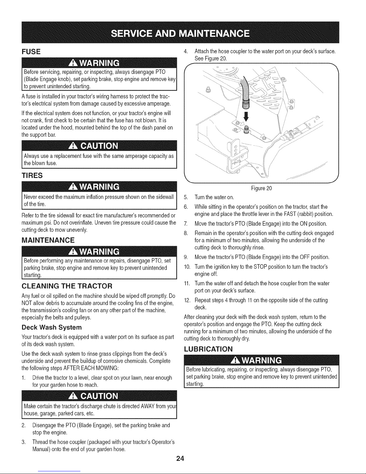
4. Attachthe hosecouplerto thewaterporton yourdeck'ssurface.
See Figure 20.
Beforeservicing,repairing,or inspecting,alwaysdisengagePTO
(BladeEngageknob),setparkingbrake,stopengineand remove
topreventunintendedstarting.
Afuse isinstalledinyourtractor'swiringharnessto protectthetrac-
tor'selectricalsystemfromdamagecausedbyexcessiveamperage.
Iftheelectricalsystemdoesnotfunction,oryourtractor'senginewill
notcrank,firstchecktobecertainthatthe fusehasnotblown.It is
locatedunderthehood,mountedbehindthe top ofthedashpanelon
thesupportbar.
Alwaysusea replacementfusewiththe sameamperagecapacityas
theblownfuse.
TIRES
Neverexceedthe maximuminflationpressureshownonthesidewall
ofthetire.
Refertothe tire sidewallforexacttiremanufacturer'srecommendedor
maximumpsi. Donotoverinfiate.Uneventire pressurecouldcausethe
cuttingdeckto mowunevenly.
MAINTENANCE
Beforeperforminganymaintenanceor repairs,disengagePTO,set
parkingbrake,stopengineand removekeyto preventunintended
starting.
CLEANING THE TRACTOR
Anyfuel oroil spilledonthe machineshouldbewipedoff promptly.Do
NOTallowdebristoaccumulatearoundthe coolingfinsofthe engine,
thetransmission'scoolingfanor onanyotherpartofthe machine,
especiallythebeltsandpulleys.
Deck Wash System
Yourtractor'sdeckisequippedwithawaterportonitssurfaceaspart
ofitsdeckwashsystem.
Usethedeckwashsystemtorinsegrassclippingsfromthe deck's
undersideandpreventthebuildupofcorrosivechemicals.Complete
thefollowingstepsAFTEREACHMOWING:
1. Drivethetractorto a level,clearspotonyour lawn,nearenough
foryourgardenhoseto reach.
\,
"\,
............. j
Figure20
.
Turnthe wateron.
6.
Whilesittingin the operator'spositionon thetractor,startthe
engineand placethethrottleleverinthe FAST(rabbit)position.
7. Movethetractor'sPTO(BladeEngage)intothe ONposition.
8. Remainintheoperator'spositionwiththecuttingdeckengaged
fora minimumoftwominutes,allowingthe undersideofthe
cuttingdeckto thoroughlyrinse.
9. Movethetractor'sPTO(BladeEngage)intothe OFFposition.
10. Turnthe ignitionkeyto the STOPpositionto turnthetractor's
engineoff.
11. Turnthe wateroffanddetachthe hosecouplerfromthewater
porton yourdeck'ssurface.
12. Repeatsteps4 through11ontheoppositesideof the cutting
deck.
Aftercleaningyourdeckwiththedeckwashsystem,returnto the
operator'spositionandengagethePTO.Keepthe cuttingdeck
runningfor a minimumof twominutes,allowingtheundersideofthe
cuttingdeckto thoroughlydry.
LUBRICATION
Beforelubricating,repairing,orinspecting,alwaysdisengagePTO,
setparkingbrake,stopengineandremovekeyto preventunintended
starting.
Makecertainthetractor'sdischargechuteisdirectedAWAYfromyoul
house,garage,parkedcars,etc.
2. DisengagethePTO(BladeEngage),settheparkingbrakeand
stoptheengine.
3. Threadthehosecoupler(packagedwithyourtractor'sOperator's
Manual)ontotheendof your gardenhose.
24
Page 25
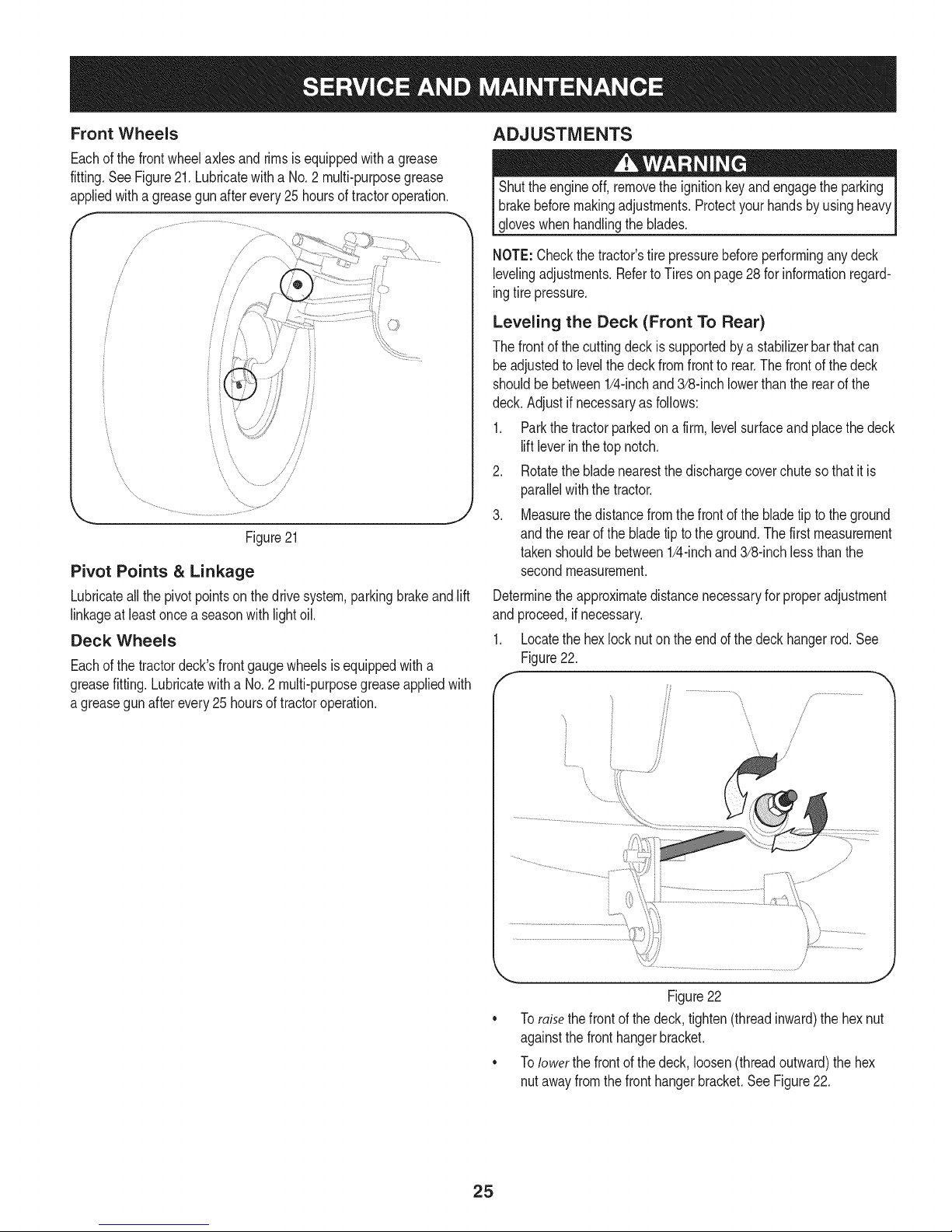
Front Wheels
Eachof thefrontwheelaxlesandrimsisequippedwitha grease
fitting.SeeFigure21.Lubricatewitha No.2 multi-purposegrease
appliedwitha greasegunafterevery25 hoursoftractoroperation.
f -,
//
_7
/
/
/
/
/
i
i
J
Figure21
Pivot Points & Linkage
Lubricateall thepivotpointson thedrivesystem,parkingbrakeandlift
linkageat leastonceaseasonwithlightoil.
Deck Wheels
Eachof thetractordeck'sfrontgaugewheelsisequippedwitha
greasefitting.Lubricatewitha No.2 multi-purposegreaseappliedwith
a greasegunafterevery25 hoursoftractoroperation.
ADJUSTMENTS
Shutthe engineoff,removethe ignitionkeyandengagetheparking
brakebeforemakingadjustments.Protectyourhandsbyusingheavy
gloveswhenhandlingthe blades.
NOTE:Checkthetractor'stirepressurebeforeperforminganydeck
levelingadjustments.Referto Tireson page28 forinformationregard-
ingtirepressure.
Leveling the Deck (Front To Rear)
Thefrontofthecuttingdeckis supportedby a stabilizerbarthatcan
beadjustedto levelthedeckfromfrontto rear.Thefrontof thedeck
shouldbebetween1/4-inchand3/8-inchlowerthantherearofthe
deck.Adjustif necessaryasfollows:
1. Parkthetractorparkedon afirm, levelsurfaceandplacethedeck
liftleverin thetopnotch.
2. Rotatethebladenearestthe dischargecoverchutesothat itis
parallelwiththe tractor.
3. Measurethedistancefromthefrontofthebladetipto theground
andthe rearofthebladetip totheground.Thefirstmeasurement
takenshouldbebetween1/4-inchand3/8-inchlessthanthe
secondmeasurement.
Determinetheapproximatedistancenecessaryfor properadjustment
and proceed,ifnecessary.
1. Locatethehexlocknuton theendofthedeckhangerrod.See
Figure22.
, y.............................
\,
Figure22
Toraisethefrontofthe deck,tighten(threadinward)thehex nut
againstthefronthangerbracket.
Tolower thefrontofthedeck, loosen(threadoutward)thehex
nutawayfromthe fronthangerbracket.SeeFigure22.
25
Page 26
Leveling the Deck (Side to Side)
Ifthecuttingdeckappearsto bemowingunevenly,a sidetoside
adjustmentcanbe performed.Adjustif necessaryasfollows:
1. Withthetractorparkedon a firm,levelsurface,placethedecklift
leverinthe topnotch(highestposition)and rotatebothbladesso
thattheyareperpendicularwiththetractor.
2. Measurethedistancefromtheoutsideof theleftbladetiptothe
groundandthedistancefromtheoutsideof the rightbladetipto
theground.Bothmeasurementstakenshouldbeequal.Ifthey're
not,proceedtothenextstep.
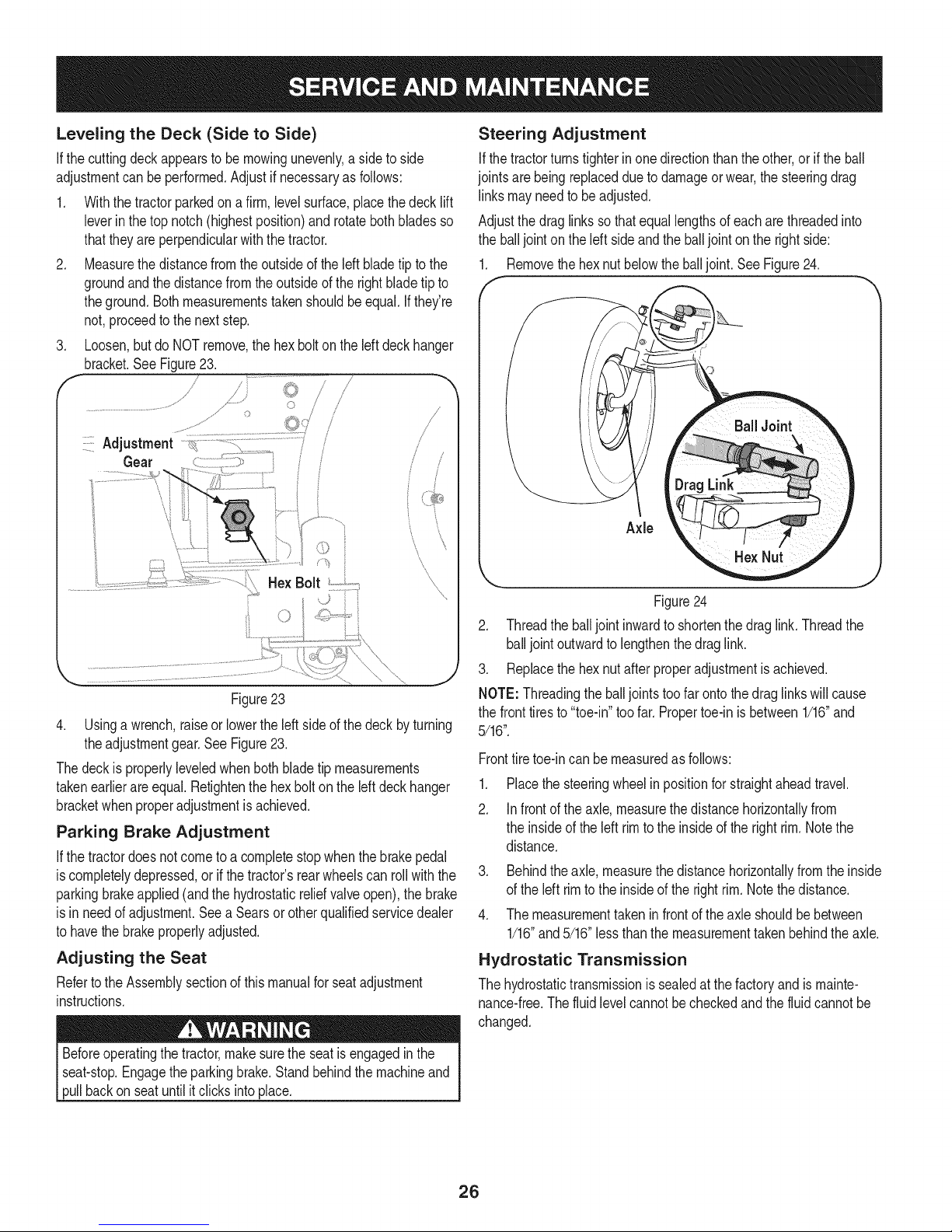
3. Loosen,butdo NOTremove,the hexboltonthe left deckhanger
bracket.See Figure23.
/
J
/ S
J
Steering Adjustment
Ifthetractorturnstighterinonedirectionthantheother,or if theball
jointsarebeingreplacedduetodamageorwear,thesteeringdrag
linksmayneedto beadjusted.
Adjustthedraglinkssothatequallengthsofeach arethreadedinto
theballjointonthe left sideandthe balljointonthe rightside:
1. Removethehexnut belowtheballjoint.SeeFigure24.
Figure23
4. Usinga wrench,raiseor lowertheleftsideof thedeck byturning
theadjustmentgear.SeeFigure23.
Thedeckis properlyleveledwhenbothbladetip measurements
takenearlierareequal.Retightenthehexbolton theleftdeckhanger
bracketwhenproperadjustmentis achieved.
Parking Brake Adjustment
Ifthetractordoesnotcometo acompletestopwhenthebrakepedal
iscompletelydepressed,or ifthetractor'srearwheelscanrollwiththe
parkingbrakeapplied(andthehydrostaticreliefvalveopen),thebrake
isin needof adjustment.Seea Searsor otherqualifiedservicedealer
tohavethebrakeproperlyadjusted.
Adjusting the Seat
Refertothe Assemblysectionofthismanualforseatadjustment
instructions.
Figure24
2. Threadthe balljointinwardto shortenthedraglink.Threadthe
balljointoutwardtolengthenthedraglink.
3. Replacethehexnut afterproperadjustmentisachieved.
NOTE:Threadingthe balljointstoofarontothedraglinkswillcause
thefronttiresto"toe-in"toofar. Propertoe-inisbetween1/16"and
5/16".
Fronttiretoe-incanbemeasuredas follows:
.
Placethesteeringwheelinpositionfor straightaheadtravel.
2.
Infrontof theaxle,measurethedistancehorizontallyfrom
theinsideoftheleft rimtotheinsideof therightrim.Notethe
distance.
3. Behindtheaxle,measurethe distancehorizontallyfromtheinside
ofthe left rimto the insideof the rightrim.Notethedistance.
4. Themeasurementtakenin frontoftheaxleshouldbebetween
1/16"and5/16"lessthanthemeasurementtakenbehindtheaxle.
Hydrostatic Transmission
Thehydrostatictransmissionissealedatthefactoryandismainte-
nance-free.Thefluidlevelcannotbecheckedandthe fluidcannotbe
changed.
Beforeoperatingthe tractor,makesuretheseatis engagedin the
seat-stop.Engagethe parkingbrake.Standbehindthe machineand
pullbackon seatuntilitclicksintoplace.
26
Page 27
DECK REAR ROLLER ADJUSTMENT
Therearrollersonthe mowerdeckarenot designedtocarrythe
weightofthe deck.Therearrollersshouldbeadjustedtoapproxi-
mately1/4"to 1/2"abovethegroundwhenthe deckis movedtothe
desiredcuttingheight.
Placethetractoron a smooth,fiatsurface,movethe deckto the
desiredcuttingheight,andcheckthe heightofthe rearrollers.If
contactingthe ground,orabove1/2"fromtheground,adjusttherear
rollersas follows:
Thedeck rollerassemblyindexbrackethasfiveadjustmentposition
holes.
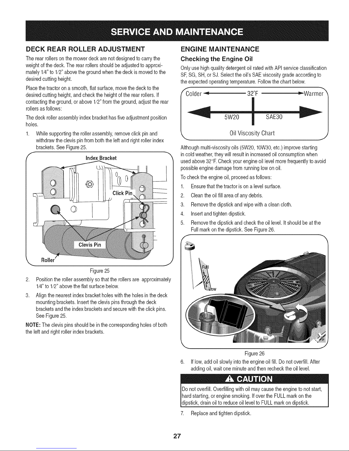
Whilesupportingtherollerassembly,removeclickpinand
withdrawtheclevispinfromboththe leftandright rollerindex
brackets.SeeFigure25.
f
Index Bracket
ENGINE MAINTENANCE
Checking the Engine Oil
Onlyusehighqualitydetergentoil ratedwithAPIserviceclassification
SF,SG, SH,orSJ. Selecttheoil'sSAEviscositygradeaccordingto
theexpectedoperatingtemperature.Followthechartbelow.
"Colder _'_ 32°F ="-Warmer_
Oil Viscosity Chart
Althoughmulti-viscosityoils (5W20,10W30,etc.)improvestarting
incoldweather,theywillresultinincreasedoilconsumptionwhen
usedabove32°ECheckyourengineoil levelmorefrequentlytoavoid
possibleenginedamagefromrunninglowonoil.
Tochecktheengineoil,proceedasfollows:
1. Ensurethatthetractoris on a levelsurface.
2. Cleantheoilfill areaof anydebris.
3. Removethe dipstickandwipewitha cleancloth.
4. Insertandtightendipstick.
5. Removethe dipstickandchecktheoillevel.It shouldbeat the
Fullmarkon thedipstick.SeeFigure26.
Roller
Figure25
2. Positionthe rollerassemblysothattherollersare approximately
1/4"to 1/2"abovetheflat surfacebelow.
3. Alignthenearestindexbracketholeswiththeholesinthedeck
mountingbrackets.Insertthe clevispinsthroughthedeck
bracketsandthe indexbracketsandsecurewiththe click pins.
SeeFigure25.
NOTE:The clevispinsshouldbeinthecorrespondingholesofboth
theleftand rightrollerindexbrackets.
J
Figure26
Iflow,addoilslowlyintotheengineoil fill. Donotoverfill.After
addingoil,waitoneminuteandthenrechecktheoillevel.
Donotoverfill.Overfillingwithoilmaycausethe enginetonotstart,
hardstarting,or enginesmoking.IfovertheFULLmarkonthe
dipstick,drainoilto reduceoilleveltoFULLmarkon dipstick.
7. Replaceandtightendipstick.
27
Page 28
Changing the Engine Oil
,
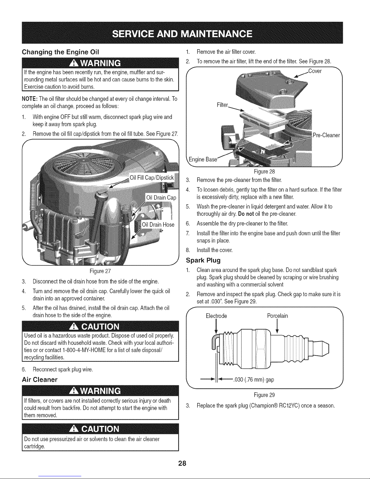
Removetheairfiltercover.
2.
Toremovetheairfilter,lifttheendof thefilter.SeeFigure28.
Iftheenginehasbeenrecentlyrun,the engine,mufflerandsur-
roundingmetalsurfaceswillbe hotandcancauseburnsto theskin.
Exercisecautionto avoidburns.
NOTE:The oilfiltershouldbechangedateveryoilchangeinterval.To
completeanoil change,proceedasfollows:
1. WithengineOFFbutstillwarm,disconnectsparkplugwire and
keepit awayfromsparkplug.
2. Removetheoil fillcap/dipstickfromtheoilfill tube.SeeFigure27.
/Cover
[Pre-Cleaner
Figure28
3. Removethe pre-cleanerfromthe filter.
4. Toloosendebris,gentlytapthefilteron a hardsurface.If thefilter
is excessivelydirty,replacewitha newfilter.
5. Washthepre-cleanerinliquiddetergentandwater.Allowit to
thoroughlyair dry.Donot oilthepre-cleaner.
6. Assemblethedrypre-cleanertothefilter.
7. Installthefilterintotheenginebaseand pushdownuntilthefilter
snapsin place.
8. Installthecover.
Figure27
3. Disconnecttheoildrain hosefromthesideof theengine.
4. Turnandremovethe oildraincap.Carefullylowerthequickoil
drainintoanapprovedcontainer.
5. Aftertheoil hasdrained,installtheoildraincap.Attachtheoil
drainhoseto thesideofthe engine.
Usedoil isa hazardouswasteproduct.Disposeof usedoil properly.
Donotdiscardwithhouseholdwaste.Checkwithyourlocalauthori-
tiesoror contact1-800-4-MY-HOMEfora listofsafedisposal/
recyclingfacilities.
6. Reconnectsparkplugwire.
Air Cleaner
Iffilters,orcoversarenotinstalledcorrectlyseriousinjuryor death
couldresultfrombackfire.Do notattempttostart theenginewith
themremoved.
Spark Plug
1. Cleanareaaroundthe sparkplugbase.Donotsandblastspark
plug.Sparkplugshouldbecleanedby scrapingor wirebrushing
andwashingwitha commercialsolvent
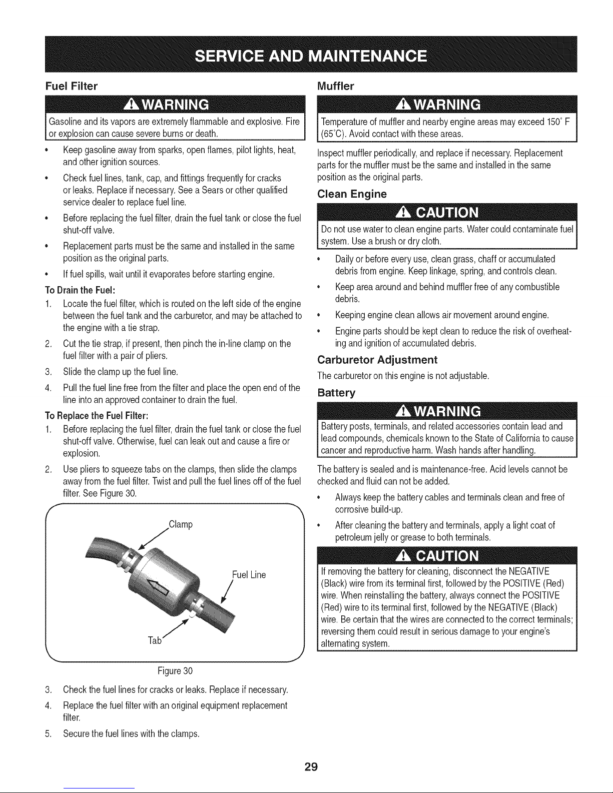
Removeandinspectthe sparkplug.Checkgapto makesureitis
setat .030".SeeFigure29.
Electrode Porcelain
_ _'_.030 (.76ram) gap
Figure29
3. Replace the spark plug (Champion® RC12YC)once a season.
Donotusepressurizedair or solventstocleanthe aircleaner
cartridge.
28
Page 29
Fuel Filter Muffler
Gasolineanditsvaporsareextremelyflammableandexplosive.Fire
or explosioncancausesevereburnsor death.
• Keepgasolineawayfromsparks,openflames,pilotlights,heat,
andotherignitionsources.
• Checkfuellines,tank,cap,andfittingsfrequentlyforcracks
orleaks.Replaceif necessary.SeeaSearsorotherqualified
servicedealerto replacefuelline.
• Beforereplacingthefuelfilter,drainthe fueltankor closethefuel
shut-offvalve.
• Replacementpartsmustbethesameandinstalledinthesame
positionasthe originalparts.
• Iffuelspills,waituntilitevaporatesbeforestartingengine.
To Drainthe Fuel:
1. Locatethefuel filter,whichis routedontheleftsideof theengine
betweenthe fueltankandthecarburetor,andmaybeattachedto
theenginewithatie strap.
2. Cutthetiestrap,if present,thenpinchthein-lineclampon the
fuelfilterwitha pairofpliers.
3. Slidetheclampupthefuel line.
4. Pullthefuellinefree fromthefilterandplacetheopenendofthe
lineintoan approvedcontainertodrainthefuel.
To Replacethe FuelFilter:
1. Beforereplacingthefuelfilter,drainthefueltankor closethefuel
shut-offvalve.Otherwise,fuelcan leakoutandcausea fireor
explosion.
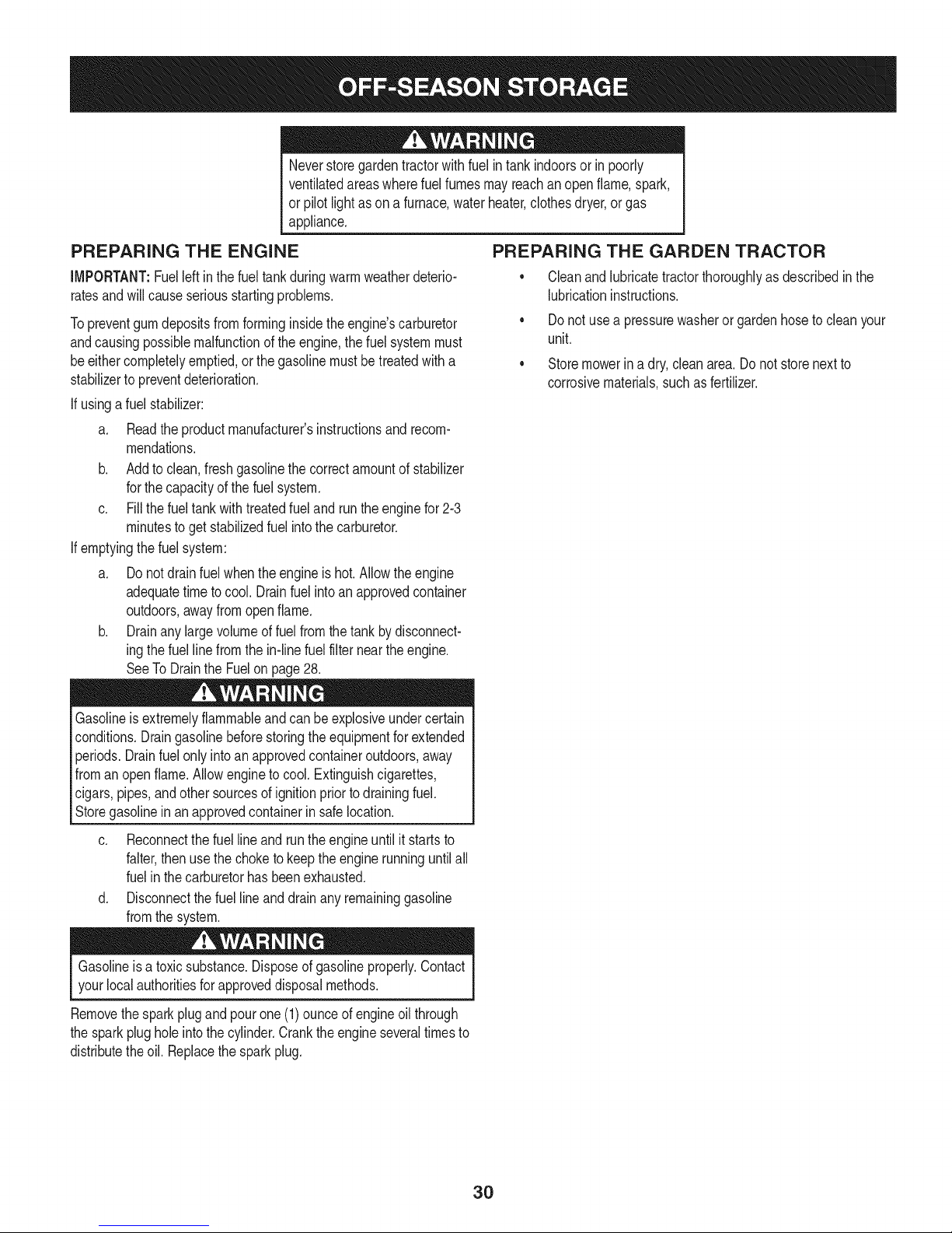
2. Useplierstosqueezetabson theclamps,then slidetheclamps
awayfromthefuel filter.Twistand pullthefuellinesoff ofthefuel
filter.SeeFigure30.
f --,
Clamp
Temperatureof mufflerandnearbyengineareasmayexceed150°F
(65°0).Avoidcontactwiththeseareas.
Inspectmufflerperiodically,andreplaceif necessary.Replacement
partsforthe mufflermustbethe sameandinstalledin thesame
positionas theoriginalparts.
Clean Engine
Donot usewatertocleanengineparts.Watercouldcontaminatefuel
system.Usea brushor drycloth.
Dailyor beforeeveryuse,cleangrass,chafforaccumulated
debrisfromengine.Keeplinkage,spring,andcontrolsclean.
Keepareaaroundand behindmufflerfreeofanycombustible
debris.
Keepingenginecleanallowsair movementaroundengine.
• Enginepartsshouldbekeptcleanto reducetheriskofoverheat-
ingandignitionofaccumulateddebris.
Carburetor Adjustment
Thecarburetoron thisengineis notadjustable.
Battery
Batteryposts,terminals,and relatedaccessoriescontainleadand
leadcompounds,chemicalsknowntotheStateofCaliforniatocause
cancerand reproductiveharm.Washhandsafterhandling.
Thebatteryissealedandis maintenance-free.Acidlevelscannotbe
checkedandfluid cannotbe added.
Alwayskeepthebatterycablesandterminalscleanandfreeof
corrosivebuild-up.
Aftercleaningthebatteryandterminals,applya lightcoatof
petroleumjellyorgreasetobothterminals.
Figure30
3. Checkthefuellinesfor cracksor leaks.Replaceif necessary.
4. Replacethefuel filterwithanoriginalequipmentreplacement
filter.
5. Securethefuellineswiththe clamps.
FuelLine
/
Ifremovingthe batteryforcleaning,disconnecttheNEGATIVE
(Black)wirefromitsterminalfirst,followedbythePOSITIVE(Red)
wire.Whenreinstallingthebattery,alwaysconnectthe POSITIVE
(Red)wire toitsterminalfirst,followedbytheNEGATIVE(Black)
wire.Becertainthatthewiresareconnectedtothecorrectterminals;
reversingthemcouldresultinseriousdamagetoyourengine's
alternatingsystem.
29
Page 30
Neverstoregardentractorwithfuel intankindoorsor in poorly
ventilatedareaswherefuelfumesmayreachan openflame,spark,
or pilotlightasona furnace,waterheater,clothesdryer,or gas
appliance.
PREPARING THE ENGINE
IMPORTANT:Fuelleftinthefueltankduringwarmweatherdeterio-
ratesandwillcauseseriousstartingproblems.
Topreventgumdepositsfromforminginsidetheengine'scarburetor
andcausingpossiblemalfunctionoftheengine,thefuelsystemmust
beeithercompletelyemptied,or thegasolinemustbetreatedwitha
stabilizerto preventdeterioration.
If usingafuelstabilizer:
a. Readthe productmanufacturer'sinstructionsand recom-
mendations.
b. Addtoclean,freshgasolinethecorrectamountofstabilizer
forthecapacityofthefuel system.
c. Fillthefueltankwithtreatedfueland runtheenginefor2-3
minutestogetstabilizedfuelintothecarburetor.
If emptyingthefuelsystem:
a. Donotdrainfuel whentheengineis hot.Allowtheengine
adequatetimetocool. Drainfuelintoan approvedcontainer
outdoors,awayfromopenflame.
b. Drainanylargevolumeoffuelfromthetankbydisconnect-
ingthefuellinefromthe in-linefuelfilterneartheengine.
SeeToDraintheFuelonpage28.
PREPARING THE GARDEN TRACTOR
• Cleanandlubricatetractorthoroughlyasdescribedin the
lubricationinstructions.
• Do notusea pressurewasherorgardenhosetocleanyour
unit.
• Storemowerina dry,cleanarea.Donot storenextto
corrosivematerials,suchasfertilizer.
Gasolineisextremelyflammableandcanbeexplosiveundercertain
conditions.Draingasolinebeforestoringtheequipmentforextended
periods.Drainfuelonlyintoan approvedcontaineroutdoors,away
fromanopenflame.Allowenginetocool.Extinguishcigarettes,
cigars,pipes,andother sourcesofignitionpriortodrainingfuel.
Storegasolinein anapprovedcontainerin safelocation.
c. Reconnectthe fuellineand runtheengineuntilit startsto
falter,thenusethe choketokeeptheenginerunninguntilall
fuelin thecarburetorhasbeenexhausted.
d. Disconnectthefuellineanddrainanyremaininggasoline
fromthesystem.
Gasolineisa toxicsubstance.Disposeof gasolineproperly.Contact
yourlocal authoritiesforapproveddisposalmethods.
Removethesparkplugandpourone(1)ounceofengineoilthrough
thesparkplugholeintothe cylinder.Cranktheengineseveraltimesto
distributetheoil. Replacethesparkplug.
30
Page 31

Beforeperforminganytypeofmaintenance/service,disengageall
controlsandstoptheengine.Waituntilallmovingpartshavecometo
a completestop.Disconnectsparkplugwireandgrounditagainstthe
engineto preventunintendedstarting.Alwayswearsafetyglassesduring
operationorwhileperforminganyadjustmentsorrepairs.
Thissectionaddressesminorserviceissues.Tolocate the nearestSearsService Centeror to scheduleservice,simplycontactSears
at 1-800-4-MY-HOME®.
Enginefailstostart
1. PTO/BladeEngageknobengaged.
2. Parkingbrakenotengaged.
3. Sparkplugwire disconnected.
4. Throttlecontrollevernotincorrectstarting
position.
5. Fueltankempty,or stalefuel.
6. BIockedfuelline.
7. Faultysparkplug.
8. Engineflooded.
9. Fuse(s)blown.
Enginerunserratically
1. Tractorrunningwith Chokeactivated.
2. Sparkplugwiresloose.
3. Blockedfuellineor stalefuel.
4. Ventingascap plugged.
5. Waterordirtin fuelsystem.
6. 6.
Dirtyair cleaner.
Engineoverheats 1. Engineoillevellow 1.
2. Airflowrestricted 2.
Enginehesitatesat high RPMs 1. Sparkpluggap settooclose 1.
Engineidlespoorly 1. Fouledsparkplug 1.
2. Dirtyaircleaner 2.
Excessivevibration 1. Cuttingbladeslooseor unbalanced 1.
2. Damaged,dull,orbentcuttingblade 2.
1. Placeknobindisengaged(OFF)position.
2. Engageparkingbrake.
3. Connectwiretosparkplug.
4. PlaceThrottleleverto FASTposition.
5. Filltankwithclean,fresh(lessthan30daysold)gas.
6. Replacefuelline.Seea Searsorotherqualified
servicedealer.Replacefuel filter.SeetheService
andMaintenancesection.
7. Clean,adjustgapor replaceplug.
8. CrankenginewiththrottleinFASTposition.
9. Replacefuse.
1. Checkthatthe electricchokeisworking.Seea
Searsorotherqualifiedservicedealer.
2. Connectandtightensparkplugwires.
3. Replacefuelline.Seea Searsorotherqualified
servicedealer.Filltankwithclean,freshgasoline
andreplacefuelfilter.Seethe Serviceand Mainte-
nancesection.
4. Clearventor replacecapifdamaged.
5. Drainfueltank.Refillwithclean,freshgasoline.See
theServiceand Maintenancesection.
Cleanorreplaceair cleanerpaperelementor clean
foampre-cleaner.
Fillenginewith properamountandtypeofoil.
Cleangrassclippingsanddebrisfromaroundthe
engine'scoolingfinsandblowerhousing.
Removesparkplugandadjustgap.
Replacesparkplugandadjustgap.
Cleanorreplaceair cleanerelementand/orclean
pre-cleaner.
Tightenbladeandspindle.Balanceblade.
Replaceblade.
31
Page 32

Mowerwill notmulchgrass
Unevencut
1. Enginespeedtoolow.
2. Wetgrass.
3. Excessivelyhighgrass.
4. Dullblade.
1. Decknotleveledproperly.
2. Dullblade.
3. Uneventirepressure.
NEED MORE HELP?
Find this and air your other product manua{s online,
Get answers from our team of home experts.
Get a persona[ized maintenance p[an for your home,
Find information and tools to help with home projects.
b_e_#]_l te yew i_- Sea_s
1. PlaceThrottlecontrolin FAST(rabbit)position.
2. Donotmulchwhengrassiswet.
3. Mowonceata highcuttingheight,thenmowagain
atdesiredheightor makea narrowercuttingswath.
4. Sharpenorreplaceblade.
1. Performside-to-sidedeckadjustment.
2. Sharpenorreplaceblade.
3. Checktirepressureinallfour tires.
32
Page 33

Congratulationson makinga smartpurchase.YournewCraftsman@
productisdesignedandmanufacturedfor yearsofdependableopera-
tion.Butlikeall products,it mayrequirerepairfromtimetotime.That's
whenhavinga RepairProtectionAgreementcansaveyoumoneyand
aggravation.
Here'swhattheRepairProtectionAgreement*includes:
* Expert service byour 10,000professionalrepairspecialists
o Unlimitedserviceand no chargeforpartsand laboron all
coveredrepairs
o Product replacementupto$1500if yourcoveredproductcan'tbe
fixed
• Discountof 10%from regularpriceofserviceandrelatedinstalled
partsnotcoveredby theagreement;also,10%off regularpriceof
preventivemaintenancecheck
• Fast help byphone- wecallitRapidResolution- phonesupport
froma Searsrepresentative.Thinkof usasa "talkingowner's
manual."
Onceyoupurchasethe Agreement,a simplephonecallisall thatit
takesfor youto scheduleservice.Youcan call anytimedayor night,or
schedulea serviceappointmentonline.
TheRepairProtectionAgreementisa risk-freepurchase.Ifyoucancel
forany reasonduringtheproductwarrantyperiod,wewillprovideafull
refund.Or,a proratedrefundanytimeaftertheproductwarrantyperiod
expires.PurchaseyourRepairProtectionAgreementtoday!
Somelimitationsandexclusionsapply. Forpricesand additional
informationin the U.S.A.call 1-800-827-6655.
*CoverageinCanadavaries on someitems.Forfull details call
SearsCanadaat 1-800-361-6665.
SearsInstallation Service
ForSearsprofessionalinstallationofhomeappliances,garagedoor
openers,waterheaters,andothermajorhomeitems,in the U.S.A.or
Canadacall1-800-4-MY-HOME®.
33
Page 34

Steering and Axle B IViodel No. 247.289842
.13
..32
39
37
35.
34
Page 35

Steering and Axle B IViodel No. 247.289842
710-04095 HexHeadScrew,3/8-16:1.00 938-04041-0637 LHAxleAssembly
2 710-0514 HexHeadScrew,3/8-16:1.00 22 710-0395 HexHeadScrew,5/16-18:2.25
3 710-0643 HexHeadScrew,5/16-18:1.00 23 710-0859 HexHeadScrew,3/8-16:2.50
4 711-04998 LHDragLink 24 710-3180 HexHeadScrew,5/16-18:1.75
5 711-04999 RHDragLink 25 912-0214 HexlockNut,3/8-24
6 912-0240 JamNut,7/16-20 26 712-04063 FlangelockNut,5/16-18
7 712-04065 FlangelockNut,3/8-16 27 714-0162 CotterPin,5/32:1.25
8 712-0459 FlangelockNut,7/16-20 28 719-04413A PivotBarAxle
9 712-3004A FlangelockNut,5/16-18 29 748-04065-0637 SteeringBlock
10 717-1550F SteeringGear 30 748-04068 Spacer,.71IDx .125ODx .56LG
11 717-1554 SteeringPinionGear 31 750-05280 Spacer,.385x 1.00x 1.5075
12 923-0448A BallJoint,7/16-20 32 631-04415 SteeringWheel
13 936-3004 FlatWasher,.406x .875x .105 33 731-06825 SteeringWheelCap
14 736-3084 FlatWasher,.51x 1.12x .06 34 731-05674 BumperCap
15 783-06043-0637 SteeringSupportBracket 35 736-04228A FlatWasher,.7811Dx 1.5900D
16 738-04263 SteeringShaft,.625ODx24.25 LG 36 634-04466-0961 WheelAssembly
17 738-04363 ShoulderSpacer,.385x 1.25x .3025 37 734-1727 Tire
18 738-04364B Spacer,.38x 1.375 38 934-04082-4042 RimAssembly
19 741-04237B HexFlangeBearing5/8 PM i39 934-0255 TubelessAirValve
20 938-04040-0637 RHAxleAssembly
35
Page 36

Hood and Dash B IViodel No. 247.289842
21
8
36
Page 37

Hood and Dash B IViodel No. 247.289842
631-04353P DashLever 731-07458 RHLens
2 710-04484 TaptiteScrew,LockWasher,5/16-18:.750 i27 731-07459 LHLens
3 710-0599 TaptiteScrew,LockWasher,1/4-20:0.500 i28 931-07461 HoodScoop
4 710-0895 Hi-LoScrew,LockWasher,1/4-15:0.750 i29 731-07467 LowerGrill
5 710-1017 Screw,1/4-14:0.625 i30 731-07711A LHHoodScoop
6 710-1611B TaptiteScrew,5/16-18:0.750 i31 731-07712A RHHoodScoop
7 710-1652 TaptiteScrew,1/4-20x .625 i32 738-04091A ShoulderScrew,.43x .29:TT:5/16-18
8 710-3217 MachineScrew,#8-32:0.375 i33 710-0642 TaptiteScrew,1/4-20:0.750
9 712-0142 HexNut,#8-32:GRA i34 747-05049 RHTankSupportRod
10 714-04040 Bow-tieCotterPin i35 747-05050 LHTankSupportRod
11 726-3046 RatchetClip:.250DIA i36 951-12179 FuelCap
12 731-07456 Dash i37 951-11650 FuelTank
13 731-07550 ControlKnob i38 925-1649 LampSocket
14 732-04580 ExtensionSpring,.500DIAx 2.733LG i39 725-04992 KeySwitchModule
15 735-0271A Bumper i40 735-04170 FuelTankGasket
16 735-04076 AccessoryNet i41 946-1100 ThrottleControl
17 747-05280 ControlRodLatch i42 731-07495 P-StylePlen
18 747-1196 LeverRod i43 725-04258 PTOSwitch
19 783-04285F-0637RHDashSupportPlate J44 925-04036C HourMeter
20 783-04323F-0637LHDashSupportPlate i45 925-0963 MiniatureLamp,12V
21 625-04124 Key(Set of2) i46 735-04081 RubberGrommet
22 683-04618-0691 HoodAssembly i47 751-12118 FuelRolloverValve
23 710-04187 Hi-loScrew,LockWasher,1/4-15:0.50 -- 777X44365 RHReflectorLabel(NotShown)
24 710-05108 Screw,LockWasher,1/4DIA:.750 -- 777X44366 LHReflectorLabel(NotShown)
25 931-07457 Grill
37
Page 38

Seat and Fender B IViodel No. 247.289842
23
33
2\
39
25
32
38
Page 39

Seat and Fender B IViodel No. 247.289842
683-04301-0637 LiftShaftAssembly 732-04563 CompressionSpring,.68x 1.065x.055
2 712-04063 FlangelockNut,5/16-18 i23 938-0296 ShoulderScrew,.437x .268:5/16-18
3 712-04065 FlangelockNut,3/8-16 i24 783-06049-0691 SeatMountingBracket
4 914-0104 CotterPin,.072DIA.x 1.13LG i25 783-06050 SeatAdjustmentLever
5 714-04040 Bow-TieCotterPin i26 783-06088-0691 SeatPivotBracket
6 716-0106A E-Ring,.625DIA.SHAFT i27 783-06448 SwitchRetainerClip
7 720-04150 HandleGrip i28 710-04187 Hi-LoScrew,LockWasher,1/4-15:0.50
8 732-0874 TorsionSpring i29 710-0451 CarriageBolt,5/16-18:.750
9 736-0105 SpringWasher,.401x .870x .063 i30 710-0599 TaptiteScrew,LockWasher,1/4-20:0.500
10 738-0138A ShoulderScrew, .437x.470:5/16-18 i31 710-0895 Hi-LoScrew,LockWasher,1/4-15:0.750
11 938-0380 ShoulderBolt,.500x.270:3/8-16 i32 731-05837 LHFenderCover
12 941-0225 HexFlangeBearing i33 731-06754 RHFenderCover
13 746-0968 LiftCable,16.16LG i34 736-3078 FlatWasher,.344x 1.00x .063 HDN
14 747-04962A LiftHandle i35 783-06118-0691 Fender
15 756-04331 PulleyRollerCable i36 726-3046 RatchetClip
16 783-05546A-0637LiftArm i37 735-04137 LHFootPad
17 710-04482 HexHeadFlange,3/8-16:.875 -- 735-04139 RHFootPad
18 710-04484 TaptiteScrew,LockWasher,5/16-18:.750 38 757-04128 Seat
19 712-3004A FlangelockNut,5/16-18 i39 957-04134 Armrests
20 i725-0157 CableTie, 3/16x.O5x 7.4 i40 783-06181-0637 LiftBracket
21 732-04849 CompressionSpring,1.71x3.735x .238 i41 925-05013 SeatSwitch
39
Page 40

Drive and Rear Wheels B Model No. 247.289842
69
7O
18
58,
7
i
11 42
49
5_
61
55
4O
Page 41

Drive and Rear Wheels B Model No. 247.289842
918-04317 WheelAssemblyHub 747-05124 BrakeRod
2 918-04917 Transmission i38 747-05125A ControlRod
3 710-0189 HexScrew,5/16-18:3.00 i39 747-05130 DisengageRod
4 710-0227 Screw,#8-18:0.500 i40 747-05181 BeltKeeper,5/16
5 710-04484 TaptiteScrew,5/16-18:.750 i41 750-04456 Spacer,260x.372x 1.420LG
6 710-0599 TaptiteScrew,1/4-20:0.500 i42 954-04244A V Belt,4Lx 77.0
7 710-0909A TaptiteScrew,5/16-18:1.750 i43 756-04224 FiatIdlerPulley,2.75OD
8 710-1007 TaptiteSeresScrew,3/8-16:1.500 i44 756-04325 V IdlerPulley,3.06
9 710-1008 TaptiteSeresScrew,3/8-16:1.875 i45 783-05443A-0637TorqueBracket
10 710-1189 Screw,#12-24:0.625 i46 783-05841 SwitchBracket
11 710-1325 TaptiteScrew,1/4-20:1.625 i47 783-06027A CenterIdlerBracket
12 710-3011 HexScrew,3/8-16:2.25 i48 783-06501A-0637DeckBracket
13 710-3119 HexScrew,3/8-16:.750 i49 783-06503 PlateBracket
14 912-0240 JamNut,7/16-20 i50 783-0693A-0637 AxleBracket
15 712-04063 FlangelockNut,5/16-18 i51 683-04571 PedalBracketAssembly
16 712-04065 FlangelockNut,3/8-16 i52 710-0604A TaptiteScrew,5/16-18:0.625
17 914-0104 CotterPin,.072DIA.x 1.13LG i53 711-05068 ClevisPin,5/16x 3.985
18 914-0111 CotterPin,3/32:1.0 i54 714-04040 Bow-TieCotterPin
19 725-0157 CableTie,3/16x .05x 7.4 i55 726-0214 PushCap
20 725-04791A JumperHarness 56 732-04587 ExtensionSpring,.63 DIAx 4.95LG
21 725-1644 ShortSpringSwitch i57 735-04118A ForwardPedalPad
22 926-0154 PushMountCableTie7.5LG i58 735-04135 ReversePedalPad
23 926-0320 InsulatorNutPlate i59 735-04136 BrakePedalPad
24 931-1449A BladeFan i60 938-0380 ShoulderBolt,.500x .270:3/8-16
25 732-04528 ExtensionSpring,.50DIAx 5.0 LG i61 741-0495 FlangeBearing,.630IDx .695ODx .60
26 732-04792 ExtensionSpring,1.00DIAx 4.75 i62 748-04203 CruiseLatch
27 732-0716D ExtensionSpring,.59ODx 4.00LG 63 783-05914 PedalSupportBracket
28 732-0932 ExtensionSpring,.38DIAx5.6 i64 783-05940 PedalSupportBracket,5/8
29 732-3118 ExtensionSpring,.375ODx 1.44LG i65 783-06059-0637 DrivePedalBracket
30 936-0227 FlatWasher,.390x 1.500x .134 i66 783-06103A-0637BrakePedalBracket
31 936-0344 FlatWasher,.330x .630x .0635 i67 634-0202A-0961 CompleteWheel
32 936-3008 FlatWasher,.344 x.750x .120 68 712-3050 LugNut,7/16-14
33 736-3010 FlatWasher,.407x .812x .135 i69 934-0255 Air Valve
34 647-04152B BrakeControlAssembly i70 734-04147-0901 Tire
35 738-04420 ShoulderSpacer,1.375x.380x .183 i71 634-04238-4042 RimAssembly
36 747-04957A FootPedalBypassTransmissionRod i72 738-1229A Shldr.Screw,.625x2.50:1/2-13
41
Page 42

Engine Accessories B IViodel No. 247.289842
14
42
Page 43

Engine Accessories B IViodel No. 247.289842
683-04549-0637 MulfflerShieldAssembly
2 710-0227 Screw,IndentedWasher,#8-18:0.500
3 710-04683 TaptiteScrew,IndentedWasher,3/8-16:1.000
4 710-0599 TaptiteScrew,IndentedWasher,1/4-20:0.500
5 710-1314A SocketHeadScrew,5/16-18:.750
6 712-0271 SeresNut, 1/4-20
7 721-0460 ExhaustGasket
8 725-0157 CableTie,3/16x .05x 7.4
9 726-0205 HoseClamp,.490DIA.
10 751-10542A Muffler
11 783-06378A HeatShield
12 751-0564B MufflerDeflector
13 751-10349 FuelHose
BS-49M877-
14 1047-G5 ReplacementEngine
43
Page 44

PTO and Battery B IViodel No. 247.289842
22
15
7
18
44
Page 45

PTO and Battery B Model No. 247.289842
710-04379A HexHeadScrew,7/16-20:3.50
2 917-1774C ElectricPTOClutch
3 725-0157 CableTie,3/16x.05x 7.4
4 936-0171 LockWasher,7/16
5 736-0277 FiatWasher,1.031x 1.620x .095
6 756-0978B ElectricPTOEnginePulley
7 683-04469B-0691 Frame
8 710-04484 TaptiteScrew,indentedWasher,5/16-18:.750
9 710-3005 HexHeadScrew,3/8-16:1.25
10 712-04065 FlangelockNut,3/8-16
11 738-04058 ShoulderSpacer,.38x 1.0x .70
12 747-04121A BatteryHolderRod
13 783-0349-0637 BatteryTray
14 783-06089-0637 SeatFrameBracket
15 i725-05088 Battery
16 i710-0653 TaptiteScrew,1/4-20:0.375
17 712-04064 FlangelockNut,1/4-20
18 725-04363 interlockSwitch
19 i725-04439 Solenoid,12V
20 i738-04237A ShoulderScrew,#10-32:.500
21 710-04666 HexHeadFlange,1/4-20:.75
22 712-0271 SemsNut,1/4-20
23 747-05195 BeltKeeperRod
NS 925-04093 WireHarnessAssembly
45
Page 46

Deck B Model No. 247.289842
22
68
54
51
_10 -
10
9
25
_"_23
I
_17
46
Page 47

Deck B Model No. 247.289842
12650 HeightAdjustBracket 732-04652 CompressionSpring,.535ODx 1.751LG
2 96606 RetainerHookBracket i42 732-04692 ExtensionSpring,.85 ODx5.915LG
3 918-04608A SpindleAssembly i43 732-0934 ExtensionSpring,1.15OD x 5.99LG
4 683-0254B-4028 DeckHangerBracketAssembly i44 734-04155 DeckWheel
5 983-04585-4028 DeckAssembly i45 936-0119 LockWasher,5/16
6 683-0459-0637 IdlerAssembly i46 936-0179 FiatWasher,.531x 1.25x .100
7 703-2093-0637 InnerBaffle i47 736-0225 LockWasher,5/8
8 703-3279-4028 DeflectorChuteStop i48 936-0300 FlatWasher,.406x .875x .059
9 710-04095 HexScrew,3/8-16:1.00 i49 936-0921 LockWasher,1/2
10 710-04484 TaptiteScrew,5/16-18:.750 i50 737-04003D DeckWaterNozzle
11 710-0521 HexScrew,3/8-16:3.00 i51 738-0295 Shaft, .750x .47.12
12 710-0528 HexScrew,5/16-18:1.25 i52 738-1229A Shldr.Screw,.625x2.50:1/2-13
13 710-0597 HexScrew,1/4-20:1.00 i53 938-3056 ShoulderBolt,.496x2.50:3/8-16
14 710-0623 TaptiteScrew,3/8-16:0.750 i54 942-0677B Blade
15 710-0859 HexScrew,3/8-16:2.50 i55 747-04938 BeltKeeperRod
16 710-3103 HexScrew,5/16-18:2.00 i56 747-05141A DeckLiftRod
17 710-3168 CarriageBolt,3/8-16:1.00 i57 712-04064 FlangelockNut, 1/4-20
18 710-3178 CarriageBolt,3/8-16:0.75 i58 747-05462 Anti-swayRod
19 911-0332 ClevisPin,.50DIAx.78 LG 59 747-1116 DeckReleaseHandleRod
20 911-3314 RollerPin, 1/2DIAx7.31LG i60 950-0212 Spacer,.82IDx 1.00ODx .53
21 912-0206 HexNut,1/2-13 i61 750-04597 Spacer,.380x.900x 1.313
22 712-0229 PushNut,3/8 i62 750-0933 Spacer,.385IDx .88x .64
23 712-04063 FlangelockNut,5/16-18 i63 954-04083 V Belt
24 712-04065 FlangelockNut,3/8-16 64 756-04129B IdlerPulley,4.25"DIA
25 712-0417A FlangeNut,5/8-18 i65 783-04013A-0637PulleyStabilizerBracket
26 912-0641 HexNut,M16-1.5DIN936 i66 783-04690B-0637DeckSkirt
27 912-3010 HexNut,5/16-18 i67 783-04726-0637 Stationaryldler Bracket
28 712-3022 HexlockNut,Counterlock,1/2-13 i68 631-04070A ChuteAssembly
29 712-3083 HexlockNut,1/2-13 i69 783-1470A-4028 RHSpindleCover
30 914-0111 CotterPin,3/32:1.0 i70 783-1471-4028 LHSpindleCover
31 914-0145 ClickPin,.092x 1.64LG 71 711-04565 HingePin
32 714-0162 CotterPin,5/32:1.25 i72 732-04372 TorsionSpring,.44IDx2.0
33 753-04070 LynchPin,.1875 i73 783-05030 ChuteBracket
34 750-1349A Spacer,.79x 1.82x.55 LG i74 756-04213 DeckPulley
35 914-0470 CotterPin, 1/8x 1.25 i75 937-3000 LubeFitting
36 715-0108 SpringPin,1/4DIAx 1.00LG 76 738-1197 SpindleShaft,6.95LG
37 917-04074 DeckGear i77 941-0919 BallBearing,.787IDx 1.85ODx.551
38 921-04041 WaterNozzleAdaptor i78 748-0160A Spacer,.790IDx 1.25ODx.175
39 731-0335 DeckRoller i79 750-1000 Spacer,.80x 1.10x 1.322LG
40 731-05679 FrontRoller
4.7
Page 48

Craftsman Engine Model491Vi777=0853=G5For Model247.289842
48 SHORT BLOCK 1058 OPERATOR'S MANUAL ] I 1329 REPLACEMENT ENGINE ] 1330 REPAIR MANUAL
850
9 - :L _- :¢
582,_
i i
i i
3
718
212 i,
505 @
448
250
1373_
4OO
o
1028
252
829
4
12
ii,
1027
552
691 @
, 1024 i_/-,>_
48
512
/ //
/ /
J J
_::::::b 524
,_-/j
Page 49

Craftsman Engine IViodel 491Vi777=0853=G5 For IViodel 247.289842
25 _._
' ,_\
_-_-_ <i,,,--_x_t!i',!' /
27 dT_i
240
212
i o
!.... j 146C7
i f
50
163 (O-}__--_-Z:-'--_
] ----<-- '(_j
51A
\
L
51A
/
49
Page 50

Craftsman Engine IViodel 491Vi777=0853=G5 For IViodel 247.289842
883 45
1022
1026 "_-_
85O
914
635
868 .....................................................
1O22
1029
1
914
50
Page 51

Craftsman Engine IViodel 491Vi777-0853-G5 For IViodel 247.289842
654
118
53 i
1169
163
418 _. _..._. ::::_/
672 X< /'\ _/
130
F_ S" :",
987 :_
}
15o_j i
1124 _:_
117
1438
14361
P
318_.,
1437_
i947
276 _
.... -\
i_ ii i ,i
385 _ lJ
24O
51
Page 52

Craftsman Engine IViodel 491Vi777=0853=G5 For IViodel 247.289842
1036 EMiSSiONS LABEL
467
1040
305 _(;) 305A ....._
304
7O3
431 186A _
J i
163 964 d; -b
/
573
186B
306
918A
964
186A
52
Page 53

Craftsman Engine IViodel 491Vi777=0853=G5 For IViodel 247.289842
1005
23
74_
1070
789
789A
334
o35_
i i
1119 G_<_
520
501
801
222
640
1439 _-_
729
1051_
783
310I>
(
i" i ,
216
8O2
53
Page 54

Craftsman Engine Model 491Vi777=0853=G5 For Model 247.289842
121 CARBURETOR OVERHAUL KiT
276 C_-I)
150
358 ENGINE GASKET SET
51A
633 0)
842_
163
12
524
2O
691 (_:;:_)
1095 VALVE GASKET SET
163 883
1O22
51A
54
Page 55

Craftsman Engine IViodel 491Vi777=0853-G5 For IViodel 247.289842
96908 CylinderAssembly
2 499585 Bushing/SealKit (MagnetoSide)
95 690718 Screw(ThrottleValve)
3 391086s Seal-Oil(MagnetoSide) 98 699721
4 797502 Sump-Engine 104 694918
5 799088 Head-Cylinder(Cylinder1) 105 797410
5A 799089 Head-Cylinder(Cylinder2) 108 699723
7 796851 Gasket-CylinderHead 117 842633
8 792185 BreatherAssembly 118 842082
9 690937 Gasket-Breather 121 796919
10 697551 Screw(BreatherAssembly) 122 796877
11 792184 Tube-Breather 125 796870
12 697227 Gasket-Crankcase 130 796875
13 793988 Screw(CylinderHead) 131 796872
16 796857 Crankshaft 133 699724
20 795387 Seal-Oil(PTOSide) 135 699729
22 694966 Screw(CrankcaseCover/Sump) 137 690994
23 691053 Flywheel 141 796228
24 796335 Key-Flywheel(Steel) 142 796871
25 796909 PistonAssembly(Standard) 146 690979
796910 PistonAssembly(020"Oversize) 150 690995
26 796911 RingSet(Standard) 163 691001
796912 RingSet(.020"Oversize) 186 796532
27 690975 Lock-PistonPin 186A 845141
28 696581 Pin-Piston 186B 799158
29 796209 Rod-Connecting 187 791766
32 690976 Screw(ConnectingRod) 188 697551
33 793557 Valve-Exhaust 192 690083
34 793556 Valve-Intake
35 694865 Spring-Valve(Intake)
36 694865 Spring-Valve(Exhaust)
42 499586 Keeper-Valve
45 690977 Tappet-Valve
46 796853 Camshaft
48 797511 Short Block
50 796878 Manifold-Intake
51 796876 Gasket-Intake
51A 690949 Gasket-Intake
53 690951 Stud(Carburetor)
54 699816 Screw(IntakeManifold)
73 494439 Screen-Rotating
74 698425 Screw(RotatingScreen)
197 697820
209 798921
211 691019
212 695238 Link-Throttle
216 796879 Link-Choke
217 695409 Spring-ChokeReturn
219 793338 Gear-Governor
220 690412 Washer(GovernorGear)
221 841026 Cup-Governor
222 798916 Bracket-Control
227 798856 Lever-GovernorControl
231 690718 Screw(ChokeValve)
240 695666 Filter-Fuel
250 690957 Retainer-Breather
691056 Washer(Flywheel)
D = 0 0
Kit-IdleSpeed
Pin-FloatHinge
Valve-FloatNeedle
Valve-Choke
Jet-Main(Standard)(Leftand RightJet)
Jet-Main(HighAltitude)(Leftand RightJet)
Kit-CarburetorOverhaul
Spacer-Carburetor
Carburetor
Valve-Throttle
Kit-ThrottleShaft
Float-Carburetor
Tube-FuelTransfer
Gasket-FloatBowl
Kit-ChokeShaft
Nozzle-Carburetor
Key-Timing
Gasket-Nozzle
Gasket-AirCleaner
Connector-Hose(Oil DrainHose)
Connector-Hose(EVAPSystem)
Connector-Hose(EVAPSystem)
Line-Fuel(Cutto RequiredLength)
Screw(ControlBracket)
Adjuster-RockerArm
Screw(BackPlate)
Spring-Governor(Orange)
Spring-GovernedIdle (NoColor)
55
Page 56

Craftsman Engine IViodel 491Vi777=O853=G5 For IViodel 247.289842
D = O !
794389 Collector-Oil
265 691024 Clamp-Casing
267 792629 Screw(CasingClamp)
276 695410 Washer-Sealing
278 792651 Washer(GovernorControlLever)
287 697551 Screw(DipstickTube)
304 797407 Housing-Blower
305 691005 Screw(BlowerHousing)
305A 790690
Screw(BlowerHousing)(BlowerHousing
to IntakeElbow)
306 796852 Shield-Cylinder(Cylinder1)
306A 796541 Shield-Cylinder(Cylinder2)
307 691003 Screw(CylinderShield)(10-24x.43)
307A 697551 Screw(CylinderShield)(1/4-20x.62)
309 795121 Motor-Starter
310 691263 Screw(StarterMotor)
318 792629
318A 691127
Screw(MountingBracket)(Electronic
ChokeModule)(10-32x.70)
Screw(MountingBracket)(Electronic
ChokeModule)(1/4-20x.81)
332 691059 Nut(Flywheel)
333 691060 Armature-Magneto
334 691061 Screw(MagnetoArmature)
337 491055s Plug-Spark
358 796917 GasketSet-Engine
385 797409 Screw(FuelPump)
387 808656 Pump-Fuel
400 796882 Cooler-Oil
404 690442 Washer(GovernorCrank)
415 794903 Plug(Oil PressureSwitchHole)
418 795912 Plate-Carburetor
431 798860 Elbow-Intake
445 792105 Filter-AirCleanerCartridge
447 691003 Screw(AirGuideCover)(10-24x.43)
447A 697551 Screw(AirGuideCover)(1/4-20x.62)
448 796865 Bracket-OilCooler
467 790697 Knob-AirCleaner
474 696458 Alternator
493 797176 Bracket-Mounting(ElectronicChoke
Module)
501 797375 Regulator
505 691029 Nut(GovernorControlLever)
D = O O
696541 Drive-Starter
512 796530 Hose-OilDrain
513 692024 Clutch-Drive
523 691036 Dipstick
524 691032 Seal-DipstickTube
525 691037 Tube-Dipstick
523 697551 Screw(Regulator)
552 796638 Bushing-GovernorCrank
552A 690553 Bushing-GovernorCrank
562 690311 Screw(GovernorControlLever)
573 790444 Plate-Back
601 691038 Hose-Clamp(Black)
601A 841597 Hose-Clamp(OilCoolerHose)
615 698290 Retainer-GovernorShaft
616 691045 Crank-Governor
633 699813 Seal-Choke/ThrottleShaft (ChokeShaft)
634 698779 Spring/SealAssembly(ChokeShaft)
635 692076 Boot-SparkPlug
640 796913 Wire-Thermistor
654 690958 Nut(Carburetor)
668 691215 Spacer(RotatingScreen)
668A 691500 Spacer(RotatingScreen)
672 690234 Gasket-CarburetorPlate
691 790574 Seal-GovernorShaft
697 690372 Screw(DriveCap)
703 691010 Clip
718 690959 Pin-Locating
729 797454 Clip-Wire
741 690980 Gear-Timing
742 690328 Retainer-ERing
750 796208 Screw(OilPumpCover)
783 695708 Gear-Pinion
789 796860 Harness-Wiring
789A 796914 Harness-Wiring
798 697890 Screw(RockerArm)
801 691283 Cap-Drive
802 691286 Cap-End
829 796867 Hose-OilCooler
842 691031 Seal-ORing(DipstickTube)
847 499602 Dipstick/TubeAssembly
850 100106 Sealant-Liquid
56
Page 57

Craftsman Engine Model 491Vi777=O853=G5 For Model 247.289842
D = O
493880s Terminal-SparkPlug
865A 792286 Cover-AirGuide(Valley)
868 690968 Seal-Valve
883 690970 Gasket-Exhaust
914 691127 Screw(RockerCover)
918 797408 Hose-Vacuum(RockerCover)
918A 799160 Hose-Vacuum(EVAPSystem)
943 796222 Seal-ORing (OilPumpCover)
947 798779 Solenoid-Fuel
964 799159 Cap-Connector
965 796221 Cover-OilPump
967 792303 Filter-PreCleaner
968 795120 Cover-AirCleaner
975 798778 Bowl-Fuel
987 691000 Seal-ThrottleShaft
1005 791236 Fan-Flywheel
1017 796214 Screen-OilPump
1022 690971 Gasket-RockerCover
1023
793146 Cover-Rocker(Cylinder1)
1023A 499600 Cover-Rocker(Cylinder2)
1024 796220 Pump-Oil
1026 690981 Rod-Push(Steel)(Exhaust)
1026A 690982 Rod-Push(Aluminum)(Intake)
1027 696854 Filter-Oil
1028 796864 Adapter-OilFilter
1029 690972 Arm-Rocker
1036
Label-Emissions(Availablefroma Briggs
&StrattonAuthorizedDealer)
1040 791237 Plate-Trim
1051 691265 Ring-Retaining
1054 280275 Tie-Cable
1058 278776 Operator'sManual
1059 698516 Kit-Screw/Washer(Alternator)
1070 791680 Screw(FlywheelFan)
1090 691293 Retainer-Brush
1095 796920 GasketSet-Valve
1000 791959 Pivot-RockerArm
1119 691183 Screw(Alternator)
1124 841653 Seal-ORing (FuelTransferTube)
1124A 690988 Seal-ORing (FuelTransferTube)
1126 690661 Screw(FuelTransferTube)
I = O O
695407 Screw(FloatBowl)
1128 690990 Screw(CarburetorNozzle)
1169 690990 Screw(CarburetorCoverPlate)
49M877-
1329 1047-G5 ReplacementEngine
1330 RepairManual(NotAvailableAtThis
Printing)
1366 796866 Diverter-OilCooler
1373 695629 Screw(OilCooler Bracket)
1374 796863 Seal-ORing(OilCoolerDiverter)
1436 796918 Motor-Stepper/Bracket
1437 699891 Screw(Stepper/BracketMotor)
1438 796532s Module-ElectronicChoke
1439 690635 Screw(ThermistorWireAssembly)
Engine Gasket SetKey No. 358
Valve Gasket Set Key No. 1095
Carburetor Overhaul Kit Key No. 121
Page 58

777123356
777123379
777D14493
777X43688 777D14480
DOHOT
USEE85ORFUEL
CUNTA|N|HGMORE
THAN10%ETHAHOL
777S30503
777X44429
mmz_ $30503
777122265
777D14486
777D14487
i_,dJ
777123357
777S33183
AVOID SERIOUS |NJURY OR DEATH
_'KEEPHANGSANDFEETAWAYFROMROTATINGPARTS.
,REMOVEOBJECTSTHATCANBETHROWNBYTHEBLADEJNANY
DIRECTION,WEARSAFETYGLASSES.
,DOHOTMOWWRENCHILDRENOROTHERSAREAROUND.
NEVERCARRYCHILDREHEVEHWiTHBLADESOFF.
,USEEXTRACAUTJQHONSLOPES.DOHOTMOWSLOPESGREATER
THAN15°,MOWACROSSHOTOFAHDDOWN.AVWSUDDENTUBHS,USELOWSPEE
777S33660
AROUND J •
_HIHH BEFOREANDWHILE J
HACHIHG. I
_RSE ISN_ RECOMMEHDED.
CHILDREHOR_ERS ARE
58
Page 59

Look For Relevant Emissions Durability Period and
Air index information On Your Engine Emissions Label
Engines that are certified to meet the California Air Resources Board (CARB) Tier 2 Emission Standards must
display information regarding the Emissions Durability Period and the Air Index. Sears Brands Management
Corporation makes this information available to the consumer on our emission labels.
The Emissions Durability Period describes the number of hours of actual running time for which the engine is
certified to be emissions compliant, assuming proper maintenance in accordance with the Operating & Mainte-
nance Instructions. The following categories are used:
Moderate: Engine is certified to be emission compliant for 125 hours of actual engine running time.
Intermediate: Engine is certified to be emission compliant for 250 hours of actual engine running time.
Extended: Engine is certified to be emission compliant for 500 hours of actual engine running time.
For example, a typical walk-behind lawn mower is used 20 to 25 hours per year. Therefore, the Emissions
Durability Period of an engine with an intermediate rating would equate to 10 to 12 years.
The Air index is a calculated number describing the relative level of emissions for a specific engine family. The
lower the Air Index, the cleaner the engine. This information is displayed in graphical form on the emissions label.
After July 1,2000, Look For Emissions Compliance Period
On Engine Emissions Compliance Label
After July 1, 2000 certain Sears Brands Management Corporation engines will be certified to meet the United
States Environmental Protection Agency (USEPA) Phase 2 emission standards. For Phase 2 certified engines, the
Emissions Compliance Period referred to on the Emissions Compliance label indicates the number of operating
hours for which the engine has been shown to meet Federal emission requirements.
For engines less than 225 cc displacement, Category C = 125 hours, B = 250 hours and A = 500 hours.
For engines of 225 cc or more, Category C = 250 hours, B = 500 hours and A = 1000 hours.
This isa generic representation of the emission label typically found on a certified engine.
FAMILYYBSXS.3192VA 274812
GDOC-100182Rev.B
59
Page 60

(Thispageapplicableinthe U.S.A.and Canadaonly.)
Sears Brands Management Corporation (Sears), the California Air Resources Board (CARD)
and the United States Environmental Protection Agency (U.S. EPA)
Emission Control System Warranty Statement (Owner's Defect Warranty Rights and Obligations)
EMISSIONCONTROLWARRANTYCOVERAGEISAPPLICABLETOCERTI-
FIEDENGINESPURCHASEDINCALIFORNIAIN1995ANDTHEREAF-
TER,WHICHAREUSEDINCALIFORNIA,ANDTOCERTIFIEDMODEL
California and United States Emission
TheCaliforniaAirResourcesBoard(CARD),U.S.EPAand Searsare pleased
toexplainthe EmissionControlSystemWarrantyonyour modelyear2000and
latersmalloff-roadengine(SORE).InCalifornia,newsmalloff-roadengines
mustbe designed,builtandequippedto meettheState'sstringentanti-smog
standards.Elsewherein theUnitedStates,newnon-road,spark-ignition
enginescertifiedformodelyear1997and latermustmeetsimilarstandardsset
forthbythe U.S.EPA.Searsmustwarranttheemissioncontrolsystemonyour
YEAR1997ANDLATERENGINESWHICHAREPURCHASEDANDUSED
ELSEWHEREINTHEUNITEDSTATES(ANDAFTERJANUARY1,2001 IN
CANADA).
Control Defects Warranty Statement
enginefortheperiodsoftime listedbelow,providedtherehasbeen noabuse,
neglector impropermaintenanceofyour smalloff-roadengine.Youremis-
sioncontrolsystemincludespartssuchas thecarburetor,aircleaner,ignition
system,mufflerandcatalyticconverter.Also includedmaybeconnectorsand
otheremissionrelatedassemblies.Wherea warrantableconditionexists,Sears
will repairyoursmalloff-roadengineatno costto youincludingdiagnosis,parts
andlabor.
Sears Emission Control Defects Warranty Coverage
Smalloff-roadenginesarewarrantedrelativeto emissioncontrolpartsdefects
fora periodof one year,subjectto provisionssetforthbelow.Ifanycovered
Owner's Warranty
Asthe smalloff-roadengineowner,you areresponsiblefor theperformanceof
therequiredmaintenancelistedinyourOperatingandMaintenanceInstruc-
tions.Searsrecommendsthatyouretainallyourreceiptscoveringmaintenance
onyoursmalloff-roadengine,butSearscannotdenywarrantysolelyfor the
lackofreceiptsorfor yourfailuretoensuretheperformanceof allscheduled
maintenance.Asthe smalloff-roadengineowner,youshouldhoweverbe
awarethatSearsmaydenyyouwarrantycoverageifyoursmalloff-roadengine
ora parthasfaileddueto abuse,neglect,impropermaintenanceor unap-
parton yourengineis defective,the partwillbe repairedorreplacedbySears.
Responsibilities
provedmodifications.Youareresponsiblefor presentingyour smalloff-road
engineto an AuthorizedSearsServiceDealeras soonasaproblemexists.The
undisputedwarrantyrepairsshouldbecompletedinareasonableamountof
time,notto exceed30days.Ifyouhaveanyquestionsregardingyourwarranty
rightsandresponsibilities,youshouldcontacta SearsService Representative
at 1-800-469-4663.The emissionwarrantyisa defectswarranty.Defectsare
judgedonnormalengineperformance.Thewarrantyis notrelatedtoan in-use
emissiontest.
Sears Emission Control Defects Warranty Provisions
ThefollowingarespecificprovisionsrelativetoyourEmissionControlDefectsWarrantyCoverage.ItisinadditiontotheSearsenginewarrantyfornon-regulated
enginesfoundin theOperatingand MaintenanceInstructions.
1. WarrantedParts
Coverageunderthis warrantyextendsonlytothe partslistedbelow(the
emissioncontrolsystemsparts)tothe extentthesepartswere presenton
the enginepurchased.
a. FuelMeteringSystem
• Cold start enrichmentsystem
• Carburetorand internalparts
• FuelPump
b. AirlnductionSystem
• Air cleaner
• Intakemanifold
c. IgnitionSystem
• Sparkplug(s)
• Magnetoignitionsystem
d. CatalystSystem
• Catalyticconverter
• Exhaustmanifold
• Air injectionsystemor pulsevalve
e. MiscellaneousItemsUsedin AboveSystems
• Vacuum,temperature,position,timesensitivevalves
andswitches
• Connectorsandassemblies
2. Lengthof Coverage
Searswarrantsto the initialownerand eachsubsequentpurchaserthat
the WarrantedPartsshallbefreefromdefects in materialsandworkman-
shipwhich causedthefailureofthe WarrantedPartsfor a periodofone
yearfromthe datethe engineis deliveredtoa retailpurchaser.
Inthe USAandCanada,a 24hourhotline,1-800-469-4663,hasa menuofpre-recordedmessagesofferingyouenginemaintenanceinformation.
3. NoCharge
Repairorreplacementof anyWarrantedPartwill beperformedat no
chargeto the owner,includingdiagnosticlaborwhichleadstothe
determinationthata WarrantedPartisdefective,ifthe diagnosticwork is
performedatanAuthorizedSearsServiceDealer.Foremissionswarranty
servicecontact yournearestAuthorizedSearsServiceDealeraslisted in
the "YellowPages"under"Engines,Gasoline,""GasolineEngines,""Lawn
Mowers,"orsimilarcategory.
4. Claimsand CoverageExclusions
Warrantyclaimsshallbe filedin accordancewiththe provisionsofthe
SearsEngineWarrantyPolicy.Warrantycoverageshall beexcludedfor
failuresof WarrantedPartswhicharenotoriginalSears partsor because
ofabuse,neglector impropermaintenanceassetforth inthe Sears
EngineWarrantyPolicy.Searsisnotliableto coverfailuresof Warranted
Partscausedby theuseof add-on,non-original,ormodifiedparts.
5. Maintenance
AnyWarrantedPartwhichis notscheduledfor replacementas required
maintenanceor whichis scheduledonlyfor regularinspectionto the effect
of"repairor replaceas necessary"shallbe warrantedasto defectsfor the
warrantyperiod.AnyWarrantedPartwhich isscheduledfor replacement
asrequiredmaintenanceshallbewarrantedasto defectsonly forthe
periodoftime upto the firstscheduledreplacementfor that part.Any
replacementpart that isequivalentin performanceanddurabilitymay
beusedin the performanceofanymaintenanceor repairs.Theowneris
responsibleforthe performanceof allrequiredmaintenance,asdefinedin
the SearsOperatingand MaintenanceInstructions.
6. ConsequentialCoverage
Coveragehereundershallextendto thefailureof anyenginecomponents
causedbythe failureof anyWarrantedPartstill underwarranty.
GD0C-100188Rev.B
60
Page 61

FEDERAL and/or CALIFORNIA EMISSION CONTROL WARRANTY STATEMENT
YOUR WARRANTY RIGHTS AND OBLIGATIONS
MTDConsumerGroupInc,the UnitedStatesEnvironmentalProtectionAgency (EPA),and,forthoseproductscertifiedforsale in the stateofCalifornia,the
CaliforniaAirResourcesBoard(CARB)are pleasedtoexplaintheemission(evaporativeand/or exhaust)controlsystem(ECS)warrantyonyouroutdoor2006
andlater smalloff-roadspark-ignitedengineandequipment(outdoorequipmentengine)InCalifornia,new outdoorequipmentenginesmustbedesigned,builtand
equippedtomeetthe State'sstringentanti-smogstandards(inotherstates,1997andlater modelyear equipmentmustbe designed,built,and equippedto meet
theU.S.EPAsmalloff-road,sparkignitionengineregulations.MTDConsumerGroupIncmustwarrantthe ECSonyour outdoorequipmentengineforthe periodof
timelistedbelowprovidedtherehasbeennoabuse,neglector impropermaintenanceofoutdoorequipmentengine.
YourECSmayincludepartssuchas thecarburetor,fuel-injectionsystem,the ignitionsystem,catalyticconverter,fueltanks,fuel lines,fuelcaps,valves,canisters,
filters,vaporhoses,clamps,connectors,andotherassociatedemission-relatedcomponents.
Wherea warrantableconditionexists,MTDConsumerGroupIncwill repairyouroutdoorequipmentengineatnocost toyouincludingdiagnosis,parts and labor.
MAN UFACTURER'S WARRANTY COVERAGE:
Thisemissioncontrolsystemiswarrantedfortwoyears. Ifanyemission-relatedpartonyour outdoorequipmentengineisdefective,the partwill berepairedor
replacedby MTDCONSUMERGROUPINC.
OWNER'S WARRANTY RESPONSIBILITIES:
Asthe outdoorequipmentengineowner,youareresponsiblefor performanceofthe requiredmaintenancelistedinyourowner'smanual.MTDConsumerGroup
Increcommendsthatyou retainallreceiptscoveringmaintenanceonyouroutdoorequipmentengine,butMTDConsumerGroupInccannotdeny warrantysolely
forthe lackof receipts.
Asthe outdoorequipmentengineowner,youshouldhoweverbe awarethat MTDConsumerGroupInc maydenyyouwarrantycoverageifyour outdoorequipment
engineor a parthasfaileddue to abuse,neglect,or impropermaintenanceor unapprovedmodifications.
Youare responsibleforpresentingyouroutdoorequipmentengineto MTDConsumerGroupInc'sdistributioncenterorservicecenterassoonasthe problem
exists.Thewarrantyrepairsshouldbecompletedin a reasonableamountoftime, notto exceed30 days.If youhaveaquestionregardingyour warrantycoverage,
youshouldcontactthe MTDConsumerGroupIncServiceDepartmentat 1-800-800-7310orvia emailathttp://support.mtdproducts.com
GENERAL EMISSIONS WARRANTY COVERAGE:
MTDConsumerGroupIncwarrantsto the ultimatepurchaserandeachsubsequentpurchaserthattheoutdoorequipmentengineis: Designed,builtand equipped
soasto conformwithall applicableregulations;and freefromdefects in materialsandworkmanshipthatcausethefailureofa warrantedpartto be identicalinall
materialrespectstothatpartas describedin MTDConsumerGroupInc'sapplicationforcertification.
Thewarrantyperiodbeginsonthedatetheoutdoorequipmentengineis deliveredto anultimatepurchaserorfirst placedintoservice.The warrantyperiodistwo
years.
Subjecttocertainconditionsand exclusionsasstatedbelow,the warrantyonemission-relatedpartsis asfollows:
1. Anywarrantedpartthat isnotscheduledfor replacementasrequiredmaintenanceinthewritteninstructionssupplied,is warrantedforthe warrantyperiod
statedabove.Ifthe partfails duringthe periodof warrantycoverage,thepartwill berepairedor replacedbyMTDConsumerGroupIncaccordingto subsection
(4)below.Anysuchpart repairedor replacedunderwarrantywillbewarrantedforthe remainderof the period.
2. Anywarrantedpartthat isscheduledonlyfor regularinspectionin the writteninstructionssuppliediswarrantedforthe warrantyperiodstatedabove.Any such
partrepairedor replacedunderwarrantywill bewarrantedforthe remainingwarrantyperiod.
3. Anywarrantedpartthat isscheduledforreplacementas requiredmaintenancein thewritteninstructionssuppliediswarrantedforthe periodoftimebeforethe
firstscheduledreplacementdateforthatpart.Ifthe partfails beforethefirst scheduledreplacement,the partwill berepairedor replacedbyMTDConsumer
GroupIncaccordingto subsection(4)below.Anysuchpartrepairedor replacedunderwarrantywillbewarrantedforthe remainderofthe periodpriortothe
firstscheduledreplacementpointfor the part.
4. Repairor replacementof anywarrantedpart underthe warrantyprovisionshereinmustbeperformedata warrantystationatno chargetothe owner.
5. Notwithstandingthe provisionsherein,warrantyservicesor repairswill beprovidedatallof our distributioncentersthatarefranchisedtoservicethe subject
enginesor equipment.
6. Theoutdoorequipmentengineownerwill notbe chargedfordiagnosticlaborthat isdirectlyassociatedwithdiagnosisof adefective,emission-relatedwar-
rantedpart, providedthatsuchdiagnosticworkis performedata warrantystation.
7. MTDConsumerGroupInc isliablefor damagestootherengineor equipmentcomponentsproximatelycausedbya failureunderwarrantyof anywarranted
part.
8. Throughoutthe off-roadengineand equipmentwarrantyperiodstatedabove,MTDConsumerGroupInc will maintaina supplyofwarrantedpartssufficientto
meetthe expecteddemandfor suchparts.
9. Anyreplacementpartmaybe usedinthe performanceof anywarrantymaintenanceor repairsandmustbe providedwithoutchargetothe owner.Suchusewill
notreducethe warrantyobligationsofMTDConsumerGroupInc.
10.Add-onor modifiedpartsthat are notexemptedbytheAirResourcesBoardmaynotbeused.The useof any non-exemptedadd-onor modifiedpartsby the
ultimatepurchaserwillbegroundsfordisallowinga warrantyclaims.MTDConsumerGroupIncwill notbe liabletowarrantfailuresof warrantedparts caused
bythe useofa non-exemptedadd-onormodifiedpart.
Page 62

WARRANTED PARTS:
Therepairor replacementofanywarrantedpart otherwiseeligiblefor warrantycoveragemaybeexcludedfromsuchwarrantycoverageif MTDConsumerGroup
Incdemonstratesthatthe outdoorequipmentenginehasbeenabused,neglected,orimproperlymaintained,and thatsuchabuse,neglect,or impropermainte-
nancewasthe direct causeof the needforrepairor replacementof the part.Thatnotwithstanding,anyadjustmentof a componentthat hasafactoryinstalled,
andproperlyoperating,adjustmentlimitingdeviceisstill eligiblefor warrantycoverage.Further,the coverageunderthis warrantyextendsonly to partsthat were
presentonthe off-roadengineand equipmentpurchased.
Thefollowingemissionwarrantypartsare covered(if applicable):
(1)FuelMeteringSystem
• Coldstart enrichmentsystem(softchoke)
• Carburetorandinternalparts(or fuel injectionsystem)
• Fuelpump
• Fueltank
(2)Air InductionSystem
• Aircleaner
• Intakemanifold
(3) IgnitionSystem
• Sparkplug(s)
• Magnetoignitionsystem
(4) ExhaustSystem
• Catalyticconverter
• SAI(Reedvalve)
(5) MiscellaneousItemsUsedin AboveSystem
• Vacuum,temperature,position,timesensitivevalvesand switches
• Connectorsandassemblies
(6) EvaporativeControl
• Fuelhose
• Fuelhoseclamps
• Tetheredfuel cap
• Carboncanister
• Vapor lines
GDOC-100223Rev.A
Page 63

Declaracion de garantia ........................ 63
Instrucciones sobre seguridad ................... 64
Guia Para Pendientes .......................... 69
Montaje ..................................... 71
Conozca su cortadora de cesped ................. 74
Funcionamiento ............................... 77
Servicio y Mantenimiento ....................... 80
Almacenamiento fuera de temporada .............. 90
Solucion de Problemas ......................... 92
Lista de piezas ............................... 34
NOmeros de servicio .................... Contratapa
CRAFTSMAN PROFESIONALES DE GARANT|A
PORDOSANOSa partirdelafechadecompra,todaslaspartesnofungiblesdeesteequipodeequitaci6nest_ngarantizadoscontracualquierdefecto
dematerialomanodeobra.UnapiezadefectuosanofungiblesrecibirAnreparaci6ngratuitaenelhogaro lasustituci6nsila reparaci6nesimposible.
Durantecincoaios desdelafechadecompra,elejedelmarcoy elfrentedeesteequipodeequitaci6nest£ngarantizadoscontracualquierdefectode
materialo manodeobra.UncuadrodefectuosooejedelanterorecibirAreparaci6ngratuitaenel hogarolasustituci6nsila reparaci6nes imposible.
Todoslosdelacoberturadelagaranfiaanteriorseaplicaparaunsoloaio desdelafechadecomprasi elequipode montaracaballoesutilizadoalguna
vez,mientrasquelaprestaci6ndeservicioscomercialesosisealquilaaotrapersona.
POR90DiASa partirdelafechadecompra,labateria(unapartefungibles)deesteequipodeequitaci6nest_garantizadacontracualquierdefectode
materialo manodeobra(nuestraspruebasdemuestraquenomantienelacarga).UnabateriadefectuosarecibirAreemplazogratuitoenelhogar.
ADICIONALDE GARANTiALIMITADADEPORVlDAen FUNDICIONeje delantero(si est_ instalado)
PARASIEMPREY CUANDOSEUTILIZAporelpropietariooriginaldespu_sdelquintoaSodesdelafechadecompra,elhierrofundidoejedelantero
(siexiste)de esteequipodeequitaci6nest_garantizadacontracualquierdefectodematerialeso manodeobra.Conelcomprobantedecompra,uneje
delanterofundidodefectuosorecibir_reemplazogratuitoenelhogar.
GARANTiABESERVlCIO
Paraobtenerinformaci6ndetaladacoberturadelagarantaparaobtenerlareparaci6no sustituci6ngratuita,lameal1-800-659-5917ovisiteelsitioweb:www.
craftsman.com
Entodosloscasosanteriores,silareparacbno reemplazodeunaparteesimposible,elequipodeequitacbnser_reemplazadodeformagratuitaconelmismoo
equivalente.
EstagarantacubrelosdefectosSOLOdematerialesyfabricaci6n.Lagarantanoincluye:
• Laspartesconsumibles(exceptolabateria)quepuedegastarseporelusonormaldentrodelperiododegaranta,incluyendoperonolimitadoa,cuchillas,
bujias,filtrosdeaire,correasy filtrosdeaceite.
• Losserviciosdemantenimiento,cambiosdeaceite,o puestasa punto.
• Tireelreemplazooreparacbndepinchazoscausadospotobjetosextemos,talescomoclavos,espinas,toconesovidrio.
• Tiredelaruedaoelreemplazoolareparacbnresultantesdeldesgastenormal,accidenteorealfuncionamientoomantenimiento.
• Lasreparacionesnecesariasdebidoalabusodeloperador,incluyendoperonolimitadoalosdaioscausadosporelremolquedelosobjetosm_sall_dela
capaddaddelequipodeequitaci6n,elimpactodeobjetosquedoblenlaestructura,elmontajedelejeodelcigOe_al,odeexcesodevelocidaddelmotor.
• Lasreparacionesnecesariasdebidoalaneglgenciadeloperador,incluyendoperonolimitadoa,da_osel_ctricosymec_nicoscausadosporunalmace-
namientoinadecuado,noutilzaci6ndelacalidadocantdaddeaceitedemotor,nomantenerelpisolbrederesiduosinflamables,o faltademantenimiento
delEquipoecuestredeacuerdoalasinstruccionescontenidasenelmanualdeloperador.
• Elmotor(sistemadecombustible)delimpiezaoreparacionesprovocadasporuncombustiblequesecontaminadouoxidado(viejo).Engeneral,el
combustibledebeserutilzadodentrodelos30diassiguientesalafechadecompra.
• deterioroydesgastenormaldelosacabadosexteriores,oreemplazodelaetiquetadelproducto.
Estagaranfialeotorgaderechoslegalesespecfficos,y ustedtambi_npuedetenetotrosderechosquevariande estadoa estado.
SearsBrands ManagementCot
Aceitedel motor:
Combustible:
Bujias:
Motor:
© KCDIRLLC 63
SAE3O
Gasolinasinplomo
Champion®RC12YC
Briggs& StrattonProfessionalSeries
_oration,Hoffman Estates,IL 60179
N_mero de rnodelo
NSmerode sede
Fechade eompra
RegistrearribaelnOmerodel modelo,
el nOmerode seriey lafechadecompra
Page 64

Lapresenciade estesirnboloindicaquesetratade instrucciones
irnportantesde seguridadquesedebenrespetarparaevitar
ponerenpeligrosu seguridadpersonaly/omaterialy lade otras
personas.Leay sigatodaslasinstruccionesdeestemanualantes
de poneren funcionarnientoestarn_.quina.Sino respetaestas
instruccionespodriaprovocarlesionespersonales.Cuandoveaeste
sirnbolo,ipresteatenci6nala advertencia!
Estarn_.quinarueconstruidaparaseroperadadeacuerdocon
lasreglasde seguridadcontenidasenestemanual.AIigualque
concualquiertipodeequipornotorizado,undescuidoo errorpor
partedeloperadorpuedeproducirlesionesgraves.Estarn_.quina
escapazde arnputarrnanosy piesy dearrojarobjetoscon gran
fuerza.De norespetarlasinstruccionesde seguridadsiguientesse
puedenproducirlesionesgraveso la rnuerte.
PROPOSICION 65 DE CALIFORNIA
Elescapedel motordeesteproducto,algunosdesuscornponentes
y algunoscornponentesdelvehiculocontieneno liberansustancias
quirnicasqueelestadode Californiaconsideraque puedenproducir
c_.ncer,defectosde nacirnientouotrosproblernasreproductivos.
Losbornesdela bateriay losaccesoriosdines contienenplornoy
cornpuestosde plorno,sustanciasquirnicasquesegQnIoestableci-
do potel EstadodeCaliforniacausanc_.nceryda_osenelsisterna
reproductivo.Ldveselasmanos despu_sde estaren contacto
con estoscomponentes.
FUNCIONAMIENTO GENERAL
• Lea,entienday curnplatodaslasinstruccionesincluidasen
la rn_.quinayen losrnanualesantesde rnontarlayutilizarla.
Guardeestemanualenun lugarseguroparaconsultasfuturasy
peri6dicas,asicornoparasolicitarrepuestos.
• Farniliaricesecontodosloscontrolesyconel usoadecuado
de losrnisrnos.Sepac6rnodetenerlarn_.quinaydesactivarlos
controlesr_.pidarnente.
• No perrnitanuncaquelosni_osrnenoresde14a_osutilicen
estarn_.quina.Losni_osde 14a_osenadelantedebenleery
entenderlasinstruccionesde operaci6nynorrnasdeseguridad
contenidasen estemanual,yen la rn_.quinay debenser
entrenadosy supervisadosporun adulto.
• Nuncaperrnitaquelosadultosoperenestarn_.quinasinrecibir
antesla instrucci6napropiada.
• Paraayudara evitarelcontactocon lascuchillasounalesi6npor
algQnobjetoqueseaarrojado,rnantengaa losobservadores,a
losayudantes,ni_osy rnascotasalejadosalrnenos25metrosde
la rn_.quinarnientrasest,.en funcionarniento.Detengalarn_.quina
sialguienentraen lazona.
• InspeccionerninuciosarnenteelAreadondeutilizar_,el equipo.
Retiretodaslaspiedras,palos,cables,huesos,juguetesyotros
objetosextra_osquepodrianser recogidosyarrojadosporla
acci6nde lascuchillas.Losobjetosarrojadosporla rn_.quina
puedenproducirlesionesgraves.
• Planifiqueel patr6ndecortedelc_spedque hadeseguirpara
evitarla descargade materialhacialoscarninos,lasveredas,los
observadores,etc. Eviteadern_.sdescargarmaterialcontralas
paredesyobstruccionesquepodrianprovocarqueel material
descargadorebotecontrael operador.
• Paraprotegerselosojosutilicesiernpreanteojoso antiparras
de seguridadrnientrasoperalarn_.quinao rnientraslaajusta
o repara.Losobjetosarrojadosque rebotanpuedenproducir
lesionesocularesgraves.
Su responsabilidad--Restrinja el usode estarn_.quina
rnotorizadaalas personasquelean,cornprendany respetenlas
advertenciase instruccionesqueaparecenenestemanualyen la
rn_.quina.
iGUARI)E ESTASINSTRUCCIONES!
• Utilicezapatosde trabajoresistentes,desuelafuerte,asicorno
pantalonesy carnisasajustados.Lasprendassueltaso las
alhajaspuedenquedaratrapadasen laspiezasrnovibles.Nunca
operela rn_.quinadescalzoo consandalias.
• Est_atentoalacortadoraya la direcci6ndela descargade
losaditarnentosy noapuntea nadie.Nuncaoperelacortadora
de cespedsinqueest_nen su lugarapropiadolacubiertade
descargao elcolectorderecortesdec_sped.
• Nopongalas rnanoso los piescercade las piezasrotatoriaso
debajode la plataforrnadecorte.Elcontactoconlas cuchillas
puedeproducirlaarnputaci6ndernanosy pies.
• Unacubiertadedescargafaltanteoda_adapuedeprovocarel
contactoconla cuchillaolesionesporobjetosarrojados.
• Detengala(s)cuchilla(s)cuandoatraviesesenderos,sendaso
carninosdegravaycuandonoest_cortandoelcesped.
• Vigileeltr_.nsitovehicularcuandoest_operandocercadeoen
crucesdecarninos.Estarn_.quinanodebeutilizarseenlavia
pQblica.
• Noopereestarn_.quinabajolosefectosdelalcoholode drogas.
• Corteel c_spedsolarnentecon luzdediao con unabuenaluz
artificial.
• Nuncatransportepasajeros.
• Desenganchela(s)cuchilla(s)antesdecolocarlarnarchaatrAs.
Retrocedalentarnente.Siernpremirehaciaabajoyhaciaatr_.santes
y rnientrasretrocede,paraevitaraccidentes.
• Reduzcalavelocidadantesdedarlavuelta.Operelarn_.quina
suavernente.Evitelaoperaci6nerr_.ticayla velocidadexcesiva.
• Desenganchela(s)cuchilla(s),coloqueelfrenodeestaciona-
rniento,detengael motory esperehastaquela(s)cuchilla(s)se
detenga(n)potcornpletoantesderetirarelcolectordec_sped,
vaciarlosrecortes,destaparelcanal,retirarrestosdecespedo
desechos,o hacercualquierajuste.
64
Page 65

• Nuncadejelarn_.quinaenfuncionarnientosinvigilancia.Apague
siernprelascuchillas,coloqueelfrenodernano,detengaelmotory
retirelaIlaveantesdebajarsedelvehiculo.
• Tengasurnocuidadoalcargaro descargarla rn_.quinaenun
rernolqueocarni6n.Estaunidadnodebeconducirseenascensoo
descensoderarnpas,porquepodrialadearsey provocarlesiones
personalesgraves.Enlas rarnpasla rn_.quinasedebeernpujar
rnanualrnenteparacargarlao descargarlacorrectarnente.
• Elsilenciadoryelmotorsecalientanypuedencausarquernaduras.
Nolostoque.
• Reviseelespaciolibrepotencirnade lacabezaantesdeconducir
bajolasrarnasbajasde _.rboles,cables,cerrarnientosde puertas,
etc.enloscualeseloperadorpodriaatorarseo seternpujadofuera
dela rn_.quina,Ioquepodriaresultarenlesionesgraves.
• Desenganchetodoslosernbraguesde losaccesoriosypresione
totalrnenteel pedaldelfrenoantesdeintentararrancarel motor.
• Larn_.quinaest,.dise_adaparacortarcespedresidencialnormal,
conunaalturanomayora 10".Nointentecortarcespeddernasiado
crecido,seco(porej.,pastura)nipilasdehojassecas.Elc_sped
ylas hojassecaspuedenentrarencontactoconelescapedel
motory/o acurnularseenla plataforrnadelacortadorade cesped,
convirti_ndoseen unpeligrodeincendio
• Utilicesolarnenteaccesoriosyaditarnentosaprobadosparaesta
rn_.quinaporelfabricantedelarnisrna.Lea,cornprenday siga
todaslasinstruccionesproporcionadasconlosaccesorioso
aditarnentosaprobados.Paraobtenerunalistadelosaccesorios
aprobadosy losarchivosadjuntos,Ilarne1-800-659-5917.
• Losdatosestadfsticosrnuestranquelosoperadoresde60 a_os
yrnayoresseveninvolucradosenunaltoporcentajedelesiones
relacionadascontractorescortacesped.Estosoperadoresdeben
evaluarsucapacidadparaoperareltractorcortac_spedenforrna
suficienternenteseguraparaprotegersea ellosrnisrnosya los
dern_.scontralesionesgraves.
Si sepresentansituacionesqueno est_.nprevistaseneste
manualseacuidadosoy use el sentidocornOn.Contacto1-800-
659-5917parainforrnaci6ny asistencia.
FUNCIONAMIENTO EN PENDIENTES
Laspendientessonunfactorirnportanterelacionadoconaccidentes
porderrapeyvuelcosquepuedenproducirlesionesgravese incluso
la rnuerte.Laoperaci6nenpendientesrequiemmayorprecauci6n.
Si nopuederetrocederen lapendienteo sino se sienteseguro,no
realiceningunaoperaci6ndecorte.
Parasuseguridad,useel indicadorde pendientesqueseincluye
cornopartedeestemanualpararnedirlapendienteantesde operarla
rn_.quinaenunazonainclinada.Si lapendienteesmayorde 15grados
segOnelrnedidor,noopereestarn_.quinaenesesector,puespodria
causarlesionesgraves.
HagaIosiguiente:
• Podehaciaarribayabajode laspendientes,node forrnatrans-
versal.Tengacuidadocuandocarnbiededirecci6nal operaren
pendiente.
• Est_atentoaloshoyos,surcos,baches,rocas,uotrosobjetos
ocultos.Elterrenodesniveladopuedevoltearlarn_.quina.Elcesped
altopuedeocultarobst_.culos.
Vayaabajavelocidad.ElijaunavelocidadIosuficienternentebaja,
de rnodoquenotengaquedetenerseo hacercarnbiosrnientras
est,.sobrelapendiente.Losneurn_.ticospodrianperdertracci6n
sobrelaspendientesa[3ncuandolosfrenosfuncionaranapro-
piadarnente.Siernprernantengala rn_.quinaencarnbiornientras
desciendelaspendientes,parapoderfrenarconel motor.
• Sigalasrecornendacionesdelfabricanteparalospesosocontra-
pesosdelas ruedas,pararnejorarlaestabilidaddela rn_.quina.
Pararecornendaciones,Ilarneal1-800-659-5917.
• Tengaespecialcuidadocon loscolectoresdec_speduotros
aditarnentos.Losrnisrnospuedenrnodificarlaestabilidaddela
rn_.quina.
• Hagaquetodoslosrnovirnientosenlaspendientesseanlentosy
graduales.Nocarnbierepentinarnentelavelocidadniladirecci6n.
Unfrenadoo carnbiodevelocidadrepentinospuedencausarque
el frentede larn_.quinaselevantey d_ unavolteretahaciaatr_.s,Io
quepodriaproducirlesionesgraves.
• Evitearrancaro detenerseenunapendiente.Silosneurn_.ticos
pierdenlatracci6n,desenganchelascuchillasydescienda
lentarnentelapendiente.
NohagaIo siguiente:
• Nogiresobrelaspendientesa rnenosqueseanecesario.Sies
posible,girelentarnentey gradualrnenteduranteeldescenso.
• Nocorteelc_spedcercadepozos,hundirnientosoterraplenes.La
cortadoradec_spedpuedevolcarserepentinarnentesiunadelas
ruedasest,.sobreel hordedeunacantilado,zanjaosiunhordese
desrnorona.
• Nointenteestabilizarlarn_.quinaponiendoelpieen elsuelo.
• Noutiliceuncolectordecespedenpendientesernpinadas.
• NopodeelcespedhOrnedo.Unarnenortracci6npodriacausar
derrapes.
• Noparadescender.Elexcesodevelocidadpuedehacerqueel
operadorpierdaelcontroldelarn_.quina,ocasionandolesiones
graveseinclusolarnuerte.
• Norernolquecargaspesadasdetr_.sdelosaditarnentos(carritode
basuracargado,podadorade rodillos,etc)enpendientesrnayores
de5 grados.Cuandosedesplazapendienteabajo,elpesoadicional
tiendeaernpujareltractorypuedehacerquesepierdaelcontrol
delmisrno(porejernplo,eltractorsepuedeacelerar,se reducela
capacidadparafrenaryrnaniobrar,losaccesoriospuedenplegarse
cornouncortaplurnasy hacerqueeltractorvuelque).
NINOS
Puedenocurriraccidentestr_.gicossi el operadornoest,.atentoa la
presenciade ni_os.PotIo general,losni_ossesientenatraidospor
estetipodern_.quinasy sufuncionarniento.Noentiendenlosriesgos
nilospeligros.Nuncaasurnaquelosni_osperrnanecer_.nenel rnisrno
lugardondelosvio porQltirnavez.
Mantengaalosni_osfueradel_readetrabajoy bajoestricta
vigilanciadeunadultoresponsableadern_.sdelpropiooperador.
Est_alertayapaguelarn_.quinasiunni_oingresaal_.rea.
Antesy rnientrasest,.retrocediendo,mirehaciaatr_.sycuidequeno
hayani_os.
Nuncatransporteni_os,aQnconlacuchillaapagada.Podriancaerse
y resultarseverarnenteheridoso interferirconlaoperaci6nsegurade
larn_.quina.
Tengaextrernaprecauci6ncuandoseaproxirnea esquinasciegas,
portales,arbustos,_.rbolesuotrosobjetosquepuedanirnpedirlever
a unni_oquesecruceenel recorridodelarn_.quina.
65
Page 66

• Paraevitaraccidentesaloperarenrnarchaatr_.s,siernpredesengan-
chelascuchillasantesdecolocarrnarchaatr_.s.Siest,.instalado,
el"ModoPrecauci6nMarchaAtr_.s"(hojasdeoperarlarn_.quina,
rnientrasquelospaseosala inversa)nodebeutilizarsecuandohay
ni_osuotraspersonaspresentes.
• Mantengaa losni_osalejadosdelosrnotoresenrnarchao calientes.
Puedensufrirquernadurasconunsilenciadorcaliente.
• RetirelaIlavecuandodejelarn_.quinasinvigilancia,evitequeuna
personasinautorizaci6nlarnaneje.
Noperrnitanuncaquelosni_osrnenoresde 14a_os utilicenesta
rn_.quina.Los ni_osde 14a_osen adelantedebenleeryentenderlas
instruccionesdeoperaci6ny norrnasde seguridadcontenidasen este
manual,yen larn_.quinaydebenserentrenadosysupervisadospor
unadulto.
REIVIOLQUE
• Rernolque_nicarnenteconunarn_.quinaquecuenteconun
enganchediseSadopararernolcar.Noacopleequiporernolcado
exceptoenelpuntodeenganche.
• SigalasrecornendacionesdelfabricanteenIoquerespectaalos
lirnitesdepesodelosequiposa rernolcaryal rernolqueenpendien-
tes.Pararecornendaciones,Ilarneal 1-800-659-5917.
• NuncaperrnitalapresenciadeniSosuotraspersonasdentroo sobre
losequiposrernolcados.
• Enlaspendientes,elpesodelequiporernolcadopuedecausar
p_rdidadetracci6ny perdidadecontroldela rn_.quina.
• Siernpreuseextralaprecauci6nrernolcandoconunarn_.quina
capazdehacervueltasapretadas(p.ejpaseo"devueltacero"-enel
cortac_sped).Hagaarnpliasvueltasparaevitaralgato-knifing.
• Despl_.ceselentarnentey dejedistanciaadicionalparafrenado.
• Noparadescender.
SERVIClO
Manejoseguro de lagasolina
Paraevitarlesionespersonaleso daSosrnaterialessea surnarnente
cuidadosoal rnanipularla gasolina.Lagasolinaessurnarnente
inflarnableysusvaporespuedencausarexplosiones.Sepuede
lesionargravernentesi derrarnagasolinasobreustedo sobrela ropa,
yaque_stasepuedeincendiar.L_.vesela pielyc_.rnbiesede ropade
inrnediato.
• Utilices61olos recipientesparagasolinaautorizados.
• NuncaIlenelosrecipientesenel interiordeunvehiculoo carni6n
ocajade rernolquecon recubrirnientopl_.stico.Coloquesiernpre
losrecipientesenel pisoylejosdel vehiculoantesderealizarla
carga.
• Cuandoseafactible,retireel equipoa gasolinadelcarni6no
rernolquey II_neloenel suelo.Siestonoes posible,Ileneel
equipoen unrernolqueconuncontenedorport_.til,envezde
hacerloconunaboquilladispensadoradegasolina.
• MantengalaboquilladeIlenadoencontactoconelhordedel
dep6sitode combustibleo conla aberturadelrecipienteentodo
rnornento,hastaterrninarlacarga.Noutiliceundispositivode
boquilladeapertura/cierre.
Apaguetodosloscigarrillos,cigarros,pipasy otrasfuentesde
cornbusti6n.
• Nuncacarguecombustibleenla rn_.quinaen unespaciocerrado.
• Nuncasaquelatapadel combustibleniagreguecombustible
rnientrasel motorest,.calienteo enrnarcha.Dejequeelmotor
seenfrie porIo rnenosdosrninutosantesdevolvera cargar
combustible.
• NuncaIleneenexcesoel dep6sitodecombustible.Lleneel
tanqueno rn_.sde 1/2pulgadapordebajode labasedelcuello
del tap6ndecarga,paradejarespacioparalaexpansi6ndel
combustible.
• Vuelvaa colocarlatapade la gasolinayajQstelabien.
• Lirnpieel combustibleque sehayaderrarnadosobreel motory el
equipo.Trasladelarn_.quinaa otrazona.Espere5rninutosantes
de encenderelmotor.
• Parareducirel riesgodeincendio,rnantengala rn_.quinalirnpia
de pasto,hojasy deacurnulaci6nde otrosresiduos.Lirnpielos
derrarnesde aceiteo combustibley saquetodoslosresiduos
ernbebidosde combustible.
• Nuncaguardelarn_.quinao el recipientedecombustibleenun
espaciocerradodondehayafuego,chispasoluz piloto,corno
por ejernplodecalentadoresdeagua,calefactoresde arnbientes,
hornos,secadoresderopau otrosaparatosagas.
• Dejequela rn_.quinaseenfriecincorninutosporIo rnenosantes
de guardarla.
Servicio general
• Nuncaenciendaelmotorenespacioscerradoso en unazona
conpocaventilaci6n.Elescapedelmotorcontienernon6xidode
carbono,ungasinodoroy letal.
• Antesde lirnpiar,repararo inspeccionarlarn_.quina,cornpruebe
que la(s)cuchilla(s)y todaslaspartesen rnovirnientose hayan
detenido.Desconecteelcablede la bujfayp6ngalohaciendo
rnasacontrael motorparaevitarqueseenciendaaccidental-
rnente.
• Reviseperi6dicarnenteparaasegurarsequelascuchillasse
detenganpotcornpletoenaproxirnadarnentecinco(5)segundos
despu_sdeaccionarel controldedesenganchedela(s)
cuchilla(s).Si lascuchillasnose detienendentrodeestelapso
de tiernpo,suunidaddeber_,serreparadaporsudistribuidorde
servicioautorizadoMTD.
• Reviseconfrecuenciael funcionarnientodel sisternade frenos
yaqueest,.sujetoa desgasteporlaoperaci6nnormal.Ajustey
efectQernantenirnientosegQnse requiera.
66
Page 67

• Reviselospernosdernontajedela(s)cuchilla(s)ydelmotora
intervalosfrecuentesparaverificarqueest_nbienapretados.
Adern_.s,inspeccionevisualrnentela(s)cuchilla(s)enbuscade
da_os(porejernplo,desgasteexcesivo,abolladuras,rajaduras,
etc.). Reernplacela(s) cuchilla(s)Onicarnenteconlascuchillas
defabricantesdeequiposoriginales(O.E.M.)listadasen este
manual.Elusode piezasqueno curnplenconlasespecifi-
cacionesdelequipooriginalpodriatenercornoresultadoun
rendirnientoincorrectoyadern_.sponeren riesgolaseguridad.
Lascuchillasdelaspodadorassonrnuyafiladas.Envuelvala
cuchillao utiliceguantesyextremelasprecaucionescuando
efectOernantenirniento.
Mantengatodoslospernos,tuercasy tornillosbienajustados
paraasegurarsede quela rn_.quinaseencuentraencondiciones
segurasde operaci6n.
Nuncaaltereel sisternade enclavarnientode seguridadni
otrosmecanisrnosde seguridad.Controleperi6dicarnenteque
funcionencorrectarnente.
Despu_sdegolpearcon algQnobjetoextra_o,detengaelmotor,
desconecteelcablede la bujfayconecteelmotora rnasa.
Inspeccionerninuciosarnentelarn_.quinaparaversiest,.da_ada.
Repareelda_oantesdearrancary utilizarla rn_.quina.
Nuncatratede hacerajusteso reparacionesala rn_.quina
rnientrasel motorest,.enrnarcha.
Loscornponentesdel colectordecespedyla cubiertade
descarga,est_.nsujetosa desgasteyda_osque podriandejar
expuestaspartesen rnovirnientoo perrnitirquesearrojenobjetos.
Paraprotegersuseguridad,verifiquefrecuenternentetodoslos
cornponentesy reernpl_.celosinrnediatarnentes61oconpiezasde
losfabricantesdel equipooriginal,listadosenestemanual.Eluso
depiezasque nocurnplenconlas especificacionesdel equipo
originalpodriatenercornoresultadounrendirnientoincorrectoy
adern_.sponeren riesgolaseguridad.
Nocarnbielaconfiguracidndel reguladordelmotorni Ioopere
a sobrevelocidad.El reguladordel motorcontrolalavelocidad
rn_.xirnaseguradefuncionarnientodelmotor.
Mantengao reernplacelasetiquetasde seguridade instrucciones
segQnseanecesario.
Respetelasnorrnasreferentesa ladisposici6ncorrectay las
reglarnentacionessobregasolina,aceite,etc.paraprotegerel
medicarnbiente.
SegOnla Cornisidnde SeguridaddeProductosparael Consu-
rnidordelos EstadosUnidos(CPSC)y laAgenciade Proteccidn
Arnbientalde losEstadosUnidos(EPA),esteproductotiene una
vidaQtilmediade siete(7) a_os,6 390horasdefuncionarniento.
AIfinalizarla vida[3tilmedia,adquieraunarn_.quinanuevao haga
inspeccionaranualrnente_staSearsporunou otrodistribuidorde
serviciosparacerciorarsedequetodoslos sisternasrnec_.nicos
yde seguridadfuncionancorrectarnenteynotienenexcesivo
desgaste.Si noIohace,puedenproducirseaccidentes,lesiones
o rnuerte.
NO MODIFIQUE EL MOTOR
Paraevitarlesionesgraveso larnuerte,nornodifiqueel motorbajo
ningunacircunstancia.Si carnbialaconfiguracidndel reguladordel
motorelmotorpuededescontrolarsey operara velocidadesinsegu-
ras.Nuncacarnbielaconfiguracidndef_.bricadelreguladordel motor.
AVISO REFERIDO A EMISIONES
Losrnotoresqueest&ncertificadosy curnplenconlas regulaciones
de ernisionesfederalesEPAy de CaliforniaparaSORE(Equipos
peque_ostodoterreno)est_.ncertificadosparaoperarcongasolina
cornOnsinplornoy puedenincluirlossiguientessisternasde control
de ernisiones:Modificacidndemotor(EM)ycatalizadorde tresvias
(TWO)si est_.nequipadosde esarnanera.
GUARDACHISPAS
Estarn&quinaest,.equipadaconunmotorde cornbusti6ninternay
nodebeserutilizadaen o cercade unterrenoagrestecubiertopor
bosque,rnalezaso hierbaexceptosiel sisternade escapedelmotor
est,.equipadocon unarnortiguadorde chispasquecurnplaconlas
leyeslocaleso estatalescorrespondientes,encasodehaberlas.
Siseutilizaun arnortiguadordechispasel operadorIodebernantener
en condicionesde usoadecuadas.Enel EstadodeCalifornialas
rnedidasanteriorrnenternencionadassonexigidasporley(Arficulo
4442del C6digodeRecursosPOblicosde California).Esposible
queexistanleyessirnilaresenotrosestados.Lasleyesfederalesse
aplicanenterritoriosfederales.
Puedeconseguirelarnortiguadorde chispasparael silenciadora
travesde sudistribuidorautorizadode rnotoreso poni_ndoseen
contactoconelcentrode servicioSears.
67
Page 68

S[IVIBOLOS DE SEGURIDAD
Estap&ginarepresentay describelaseguridadlossimbolosquepuedenparecerenesteproducto.Lea,comprenda,ysigatodasinstrucciones
en lam_quinaantesprocurarparareuniry operar.
i
i
®
J
LEA EL MANUAL(S) DEL OPERADOR
leido, entienda, y siga todas las instrucciones en el manual(s) antes de procurar montar y funcionar
PELIGRO-- DE ELCORTE DE PIE
Nunca transporte pasajeros. Nunca transporte nihos, aun con la cuchilla apagada.
PELIGRO-- DE ELCORTE DE PIE
Retroceda lentamente. Siempre mire hacia abajo y hacia atr_is antes y mientras retrocede, para evitar
accidentes.
PELIGRO-- DE ELCORTE DE PIE
Guarde manos y pies lejos de hacer girar partes.
PELIGRO-- ESCOMBROS LANZADOS
Quite objetos que pueden set lanzados pot la I_imina en cualquier direcci6n. Lleve galas de
seguridad..
PELIGRO-- ESCOMBROS LANZADOS
Quite objetos que pueden set lanzados pot la I_imina en cualquier direcci6n. Lleve galas de
seguridad.
®
,E,
AL
ERSONAS PRESENTES
Guarde alas personas presentes, a los ayudantes y a nihos pot Io menos 75 pies lejos.
PELIGRO-- CUESTAS
Use extra la precauci6n en cuestas. No siegue cuestas mayores que 15°.
ADVERTENCIA-- SUPERFICIE CALIENTE
Las partes del motor, especialmente el silenciador, Ilega a set muy caliente durante la operaci6n.
Permita motor y silenciador para ponerse frio antes de tocar.
PELIGRO-- GIRANDO HOJAS
Para reducir el riesgo de herida, guarde manos y pies lejos. No funcione a menos que la tapa
de descarga o el receptor de hierba est6n en su lugar apropiado. De ser dahado, sustituya
inmediatamente.
68
Page 69

15°
I
I
r,o
Use esta paginacomo guiapara determinar en qu_ pendientes no puede operar eltractor de manera segura.
Nooperelacortadoradecespedendichaspendientes.Nocorteen inclinacionesmayoresde15grados(elevaci6naproximadade2 1/2piespotcada 10pies). Eltractor
cortacespedpodriavoltearseycausarlesionesgraves.En laspendientesopereconlostractorescorta-cespedhaciaarribay abajo,nuncadeformatransversal.
Page 70

Estapgtginasemarch6 intencionadamenteen blanco.
70
Page 71

CONFIGURACION DEL TRACTOR
IViovirniento manual del tractor
Latransmisi6nde sutractorvieneequipadacon unav_Jvulade
descargahidrost_.ticaparalasocasionesen queseanecesario
movereltractormanualmente.AIabrirestavAJvulael liquidoen
latransmisi6npuedeevitarsuruta normal,permitiendoquelos
neum_.ticostraseros"ruedenlibremente".Paraabrirlav_Jvulade
descargahidrost_.tica,procedade la siguientemanera:
1. Localicelavarilladederivaci6nhidrost_.ticaen la partetrasera
deltractor.VealaFigura1.
,,,"J/
\
Extracci6n de la traba de seguridad utilizada en el envio
AsegQresedequeel motordel tractorcortac_spedest_apagado,
coloqueelfrenode manoyquitela Ilavedeencendidoantesde
retirarlatraba deseguridadutilizadaen el envio.
1. Localicelatrabade seguridad,sihubiere,y laetiquetade
advertenciaencontradaen la partederechadela plataformade
corte.Veala Figura2.
f x \\
x\ \\
\\
Figura1
2. Tiredelavarilladederivaci6nhidrost_.ticahaciaafuera,luego
haciaabajoparatrabarlaen sulugar.
NOTA:Latransmisi6nNOseenganchar_,cuandolavarillade
derivaci6nhidrost_.ticasetirehaciafuera.Regresela varillaa su
posici6nnormalantesdeoperarel tractor.
AsegQresede queel motordeltractorcortac_spedest_apagado,
coloqueelfrenodemanoyquite la Ilavedeencendidoantesde
retirarlatrabade seguridadutilizadaenel envio.
Figura2
.
Mientrassostieneel canalde descargaconsumanoizquierda,
extraigaconla manoderechalatrabadeseguridad,sujet_.ndola
entrelosdedospulgare indiceyrot_.ndolaenel sentidode las
agujasdel reloj.
LatrabadeseguridadseusaQnicamenteparael embalaje.Retirey
desechela trabadeseguridadutilizadaen elenvio antesde operar
sutractorcortacesped.
3roducirsecraveslesiones#ersonalesy/o da_osmateriales.
71
Page 72

CONEXION DE LOS CABLES DE LA BATERiA Control de la presi6n de los neumaticos
Nuncaexcedalapresi6nmaximadeinfladoqueseindicaenloslaterales
delosneum_.ticos.Noinfielosneum_.ticosenexceso.Consulteenlos
lateralesdelosneum_.ticoslapresi6nmaximaenpsi Sedebemantener
3uesdeestarencontactoconestoscomponentes.
Cuandocoloqueloscablesdelabateria,conectesiempreprimeroelcable
POSITIVO(rojo)a suborne,yacontinuaci6nelcableNEGATIVO(negro).
unapresi6nuniformeparatodoslosneum_.ticosentodomomento.
Esposiblequelosneurn_.ticosde[tractorhayansidoinfladosen
excesoparadespacharlo.Reduzca[apresi6nde losneurn_.ticosantes
de operarel tractor.Consuiteenlos[ateralesdelosneurn_.ticos[a
presi6nrn_.xirnaen psi
Porrazonesrelacionadasconel ernbarque,losdoscablesdela
bateriadesu equipopuedenhabersidodesconectadosde losbornes
enf_.brica.Paraconectarloscablesdela bateria,procedadela
siguienternanera:
NOTA:El bornepositivodela bateriaest,.rnarcadocornoPos(+).El
bornenegativodela bateriaest,.rnarcadocornoNeg(-).
NOTA:Si elcablepositivodelabateriayaest,.conectado,sigaconel
paso2.
Retirela cubiertapl_.stica,siesqueest,.presente,del borne
positivodela batefiay unael cablerojoal bornepositivodela
bateria(+)utilizandoel pernoy latuercahexagonal.
Veala Figura3.
f
Ajuste del asiento
Paraajustarla posici6ndel asiento,firelohaciaarribaysostengala
palancadeajustedel asiento.Desliceel asientohaciaadelanteo
haciaatr_.sa la posici6ndeseada;luegosueltela palancadeajuste.
AsegQresedequeel asientoest_trabadoen untopede asientoantes
de operarel tractor.Veala Figura4.
arhaciendoclic.
Figura3
.
Retirela cubiertapl_.stica,siesqueest,.presente,del borne
negativode la bateriayunael cablenegroal bornenegativodela
bateria(-) utilizandoel pernoyla tuercahexagonal.VealaFigura
3.
3. Coloqueelcapuch6nde gornarojoporencirnadelbornepositivo
dela bateriaparaprotegerlocontrala corrosi6n.
NOTA:Si labateriaseponeen funcionarnientodespu_sde lafecha
indicadaensu partesuperioroalcostadodela rnisrna,c_.rguela
siguiendolasinstruccionesde la secci6nMantenirnientode este
manualdeloperadorantesde hacerfuncionareltractor.
Figura4
Paraajustarel _.ngulodelosbrazos,levantarlosbrazosy girarla
perilladeajustede alturadelasagujasdelrelojparadisrninuirel
_.nguloo la izquierdaparaaurnentarel _.ngulo.VeaFigura4.
72
Page 73

Ajuste de las ruedas de calibraci6n de la
plataforma y rodillo
Muevaeltractora unasuperficiefirrneynivelada,preferenternente
sobreel pavirnento,y realiceIosiguiente,
1, Selecdonela posicbnde alturadela plataforrnade corte
colocandola palancadeelevad6ndela plataforrnaenel ajuste
dealturade cortedeseadoensituaci6nnormal(cualquiera
de lasseisrnuescasdealturadecortedel ladoderechodel
guardabarros).
2, Controlesilasruedasde calibraci6nest_.nencontactoconla
superfidedeabajoo si hayexcesivaseparad6n,Debehaberuna
separad6ndeentre 1/4 pulgaday 1/2pulgadaentrelasruedas
decalibraci6nde la plataforrnayel suelo.
Si lasruedasdecalibraci6ntienenexcesivaseparaci6nrespectodel
sueloo est_.nen contactoconel rnisrno,ajustedelsiguienternodo:
a. Levantelarnanijadeelevaci6ndelaplataforrnahastael
puntorn_.salto.
b. Extraigalasruedasdecalibraci6nretirandolastuercas
de sujeci6ny lostornilloscon rebordequelasajustana la
plataforrna.Veala Figura5.
c. Coloquelapalancadeelevaci6nde la plataforrnaenel
ajustede alturadecortedeseado.
d. Vuelvaainsertareltornillocon reborde(concadaruedade
calibraci6n)dentrodel orificiode posicionarnientoquedeja
aproxirnadarnente1/2pulgadaentrela parteinferiordela
rueday el pavirnento.
e. Extraigalospasadoresde chavetay lospasadoresde
horquillade lasrn_nsulasdel rodillode la plataforrnasobre
losladosizquierdoy derechodelaplataforrnade corte.Vea
la Figura5.
f. Posicionelasrn_nsulasdel rodillode la plataforrnahacia
arribao haciaabajoatravesde lasranurassobrelaparte
posteriorde la plataforrnahastaquesehayaalcanzadola
posici6ndeseada,luegovuelvaacolocarconlos pasadores
dechavetay horquillaqueextrajoantes.AsegQresede
quela rn_nsuladel rodilloizquierdoyla rn_nsuladel rodillo
derechoest_ncolocadasen larnisrnaposici6n.
Consultelasecci6nNivelaci6nde la Plataforrnaen la secci6n
Mantenirnientodeeste manualparaobtenerinstruccionesdetalladas
sobrediferentesajustesdela plataforrna.
f
i[ \ .............
Gasolina y aceite
EltanquedecombustibleestAubicadodebajodelcap6y tieneuna
capacidadde tresgalonesy rnedio.Quitelatapadecombustible
gir_.ndolaensentidocontrarioalde lasagujasdelreloj.Utilice
Qnicarnentegasolinalirnpia,nueva(norn_.sde 30 diasdeuso)y sin
plorno.Lleneel tanqueano rn_.sde cuatropulgadaspordebajodel
hordesuperiordelcuellode Ilenadoparaperrnitirlaexpansi6ndel
combustible.
Tengamuchocuidadoaltrabajarcongasolina.Lagasolinaessumamente
inflamableysusvaporespuedencausarexplosiones.Nuncaagregue
combustiblealamAquinaeninterioresnimientraselmotorestacaliente
oenfuncionamiento.Apaguecigarrillos,cigarros,pipasy otrasfuentesde
combusti6n.
NOTA:Sutractorseenviaconaceiteenel motor.Sinembargo,usted
DEBEcontrolarel nivelde aceiteantesde hacerlofuncionar.Vea
Controldelaceitedelmotoren la secci6nServicioy Mantenirnientode
estemanual.
Controlesiempreel nivelde aceitedelmotorantesdecadausocorno
seindicaenla secci6nMantenirnientodeestemanual.Agregueaceite
segunseanecesario.Denohacerlosepuedenproducirda_osgraves
al motor.
Figura5
J
73
Page 74

f
Monitordel indicador
de sistemas
Tap6ndeltanque de combustible
Control del reguladc
I
Indicador de nivelde combustible
Pedalde freno
Frenode mano/ palanca
decontrolde crucero
Palancade ajuste delasiento
Portacubeta
M6dulodel interruptorde
encendido
Perillade potenciade arranque
(PTO)(enganche de cuchilla)
Pedalde la transmisi6n
Pedalde marcha atr_s
Palancade elevaci6n
de la plataforma
\
Figura6
Loscontrolesyfuncionesdel tractorcortacespedseilustranenla
Figura6y sedescribenenlasp_.ginassiguientes.
NOTA:Las referenciasa laderechaodej6ladode tractoresdel punto
devistadeloperariofrentea delanterodel asientode tractor.
Leay respetetodaslasnormasde seguridady lasinstruccionesde I
estemanual,incluidala secci6nFuncionarnientoensutotalidad,antesI
de intentaroperarestam_.quina.Sino respetatodaslasnormasde
segurdady as nstrucconespuedecausaresonespersonaes. I
PEDAL DE FRENO
Elpedaldefrenoest,.ubicadoadelantea la
izquierdadel tractor,porencimadelpedal
detransmisi6n,sobreel estribo.Elpedal
defrenosepuedeusarparadetenciones
bruscasoparacolocarelfrenodemano.
NOTA:Sedebepresionartotalmenteel pedaldelfrenoparaactivarel
interruptordel dispositivodeenclavamientoalencendereltractor.
PALANCA DE CONTROL DEL REGULADOR
Elcontroldel reguladorseencuentradelladoizquierdodel panel
de instrumentosdel tractor.Estapalancacontrolala velocidaddel
motor.Cuandose Iocolocaenunaposici6ndeterminada,el regulador
mantieneunavelocidaddemotoruniforme.
NOTA:Cuandoopereel tractorconla plataformadecortecolocada,
asegQresede quela palancadelreguladorest_siempreenla posici6n
FAST(r_.pido;representadoporunaliebre).
PALANCA DE AJUSTE DEL ASIENTO
Lapalancadeajustedelasientoest,.ubicadadebajodelasiento,
adelanteala izquierda.Lapalancapermiteelajustedel asientodel
operador,haciaadelanteo haciaatr_.s.Consultela secci6nMontaje
de estemanualparavet instruccionesm_.sdetalladas.
74
Page 75

PALANCA DE ELEVACI6N
DE LA CUBIERTA
Ubicadaenel guardabarrosderecho i
deltractor,la palancadeelevaci6nde la V
plataforrnaseutiNzaparacarnbiarlaaltura
dela plataforrnade corte.ParautiNzarla,
rnuevalapalancahaciala izquierda,luego
col6quelaenla rnuescaquernejorse
adapteala apNcaci6ndeseada.
M6DULO DEL INTERRUPTOR DE ENCENDIDO
Paraencenderelmotor,insertela Nave
enel interruptordeencendidoygfrela
enel sentidode lasagujasdel reloj
haciala posici6nSTART(arranque).
SueltelaNaveen la posici6nMODO
NORMALDECORTEunavezque haya
arrancadoel motor.
Paradetenerelmotor,girela Navede
ignici6nensentidocontrariodelas
agujasdelrelojhastalaPOSlCIONDE
STOP(detener).
Nuncadejelam_.quinaenfuncionamientosinvigilancia.Siempredesconecte
laPTO(perilladeenganchedecuchilla,coloqueelfrenodemano,apagueel
motory retirelaIlave,paraevitarquealguienenciendaaccidentalmenteelmotor.
Antesdeoperarel tractor,consulte.LosInterruptoresde InterbloqueoI
de Seguridady Poneren MarchalaM_.quinaenla secci6n I
Funcionarnientode estemanualparaverinstruccionesdetalladasdelI
M6dulodeInterruptorde EncendidoyOperarel Tractoren MODO
PRECAUCON MARCHAATRAS. I
PEDAL DE LA TRANSMISI6N
Elpedalde latransrnisi6nest,.ubicadoala
derechadeltractor,sobreel estribo.Presioneel
pedalde transrnisi6nhaciaadelanteparaqueel
tractorse rnuevahaciaadelante.Lavelocidad
absolutatarnbi@nse controlaconel pedaldela
transrnisi6n.Cuantorn_.sse presioneel pedal
haciaadelante,rn_.sr@idose rnover_,eltractor.
Elpedalvolver_,a suposici6noriginalcuando
dejedepresionarlo.
PEDAL DE MARCHA ATRAS
Elpedalde rnarchaatr_.sest,.ubicadoala
derechadeltractor,sobreel estribo. Lavelocidad
absolutatarnbi_nsecontrolaconel pedalde
rnarchaatr_.s.Cuantorn_.sse presioneelpedal
haciaabajo,rn_.sr@idosernover_,eltractor.El
pedalvolver_,a suposici6noriginalcuandodejede
presionarlo.
_NO CHILDREN AROUND
d
II
II
LCD MONITOR INDICADOR DE SISTEMAS/
MEDIDOR HORARIO
CuandolaNavede encendido
serotafueradelaposici6n
STOP(parar)peronose
colocaenla posici6nSTART
(encendido),el monitor
indicadorde sisternasrnuestra
lasalidade labaterfa,en
voltios,en suLCD(pantalla
de cristalIfquido)durante
aproxirnadarnentecinco
segundos,ydespu_srnuestra
unrelojdearenay las horas
de funcionarnientodel tractor.Unavezquehayaarrancadoeltractor,
el monitorcontinuarnenternuestraunrelojdearenay lashorasde
funcionarnientodeltractorensu LCD.
NOTA:Lashorasde funcionarnientodeltractorse registrancada vez
que laNavede encendidose rotafueradela posici6nSTOP(parar),
independienternentedequesehayaarrancadoel motor.
Elmonitorindicadortarnbi_nlerecuerdaaloperadorlosintervalos
de rnantenirnientoparacarnbiarelaceitedelmotor.Lapantallade
cristalIfquidoparpadeaalternativarnentelashorasregistradas,"CHG"
(CAMBIO)y"OIL"(ACEITE)durantecincorninutos,despu_sde que
hayanpasado50 horasdefuncionarnientoregistrado.Elintervalode
rnantenirnientodurados horas(entre50-52,100-102,150-152,etc.) La
pantaNadecristalIfquidotarnbi_nparpadeaseg_nsedescribern_.s
arriba,durantecincorninutos,cadavezque elmotordel tractorse
enciendeduranteelintervalode mantenirniento.Antesdeque finance
el intervalo,carnbieelaceitedelmotorsegOnseindicaen la secci6n
Servicioy Mantenirnientodeeste ManualdelOperador.
Freno
Siseilurninalaluzdefrenoal intentarencenderel motordel tractor,
presioneel pedaldelfreno.
Potencia de arranque (PTO) (enganche de cuchilla)
Sila luzde la potenciade arranque(PTO)seilurninaalintentar
encenderelmotordeltractor,presionela perillade potenciade
arranque(PTO)enla posici6ndesenganchada(OFF).
Aceite
Esnormalquela luzde aceitese ilurninecuandoel motorest,.girando
duranteelarranque,perosiseilurninadurantelaoperaci6n,cuando
el motorest,.funcionando,detengael tractordeinrnediatoycontrole
el nivelde aceitedel motorsegOnlasinstruccionesdeeste Manualdel
operador.
Bateria
Esnormalquela luzde la baterfase ilurninecuandoel motorest,.
girandoduranteelarranque,perosiseilurninadurantela operaci6n,
cuandoel motorest,.funcionando,la baterfanecesitacargao el
sisternade cargadelmotorno est,.generandoarnperajesuficiente.
Carguelabaterfacornoseindicaen la secci6nServiciodeeste
manualohagaqueel sisternade cargasea verificadopot su
distribuidorSearsuottodistribuidordeserviciocalificado.
o
o (P) o
75
Page 76

PERILLA DE POTENCIA DE ARRANQUE
(PTO)/ENGANCHE DE CUCHILLA PTO
AIconectarla potenciadearranque(PTO)se
surninistraalirnentaci6nala plataforrnade corte
o aotrosaccesorios(disponiblesporseparado).
Tirehaciaafuerade lapotenciadearranque/
enganchedecuchillaparaactivada.Presione
la perillapotenciade arranque(PTO)/enganche
decuchillaparadesconectarlaenergfade
la plataforrnadecorteu otrosaccesorios
(disponiblesporseparado). OFF ON
NOTA:AI encenderel motor,laperillapotencia
dearranque(PTO)/enganchedecuchilladebeencontrarseen la
posici6ndeapagado(OFF).
FRENO DE MANO / PALANCA DE CONTROL
DE CRUCERO
Lapalancadefrenode rnano/controlde crucero,
ubicadaenelcentrodeltablerodecontroldeltractor,
debajodelvolante,seutilizaparaengancharelfreno
dernanoy elcontrolde crucero.Consultelasecci6n
Funcionarnientodeestemanualparavet instrucciones
detalladassobreelfrenodernano.
NOTA:Si eloperadorabandonaelasientoy dejael
motorfuncionando,deber&colocarel frenodernano,o
el motorseapagar&de forrnaautorn&tica.
NOTA:ElcontroldecruceroNOpodr&activarsea
lavelocidadabsolutarn&sr&pidadeltractor.Siel
operadorintentaactivarloen esascondiciones,el
tractorsedesacelerar&autorn_.ticarnentea la velocidad
decorteabsoluta6ptirnayrn&sr&pida.
Nuncadejela rn&quinaen funcionarnientosinvigilancia.Siernpre
desconectela PTO(perilladeenganchedecuchilla,coloqueel freno
dernano,apagueelmotory retirelaIlave,paraevitarquealguien
enciendaaccidentalrnenteel motor.
INDICADOR DE NIVEL DE COMBUSTIBLE
El indicadorde niveldecombustibleest_ubicadoa la derecha
delpanelde instrurnentosdeltractore indicalacantidadde
combustibleen eltanque.
76
Page 77

INTERRUPTORES DE BLOQUEO DE SEGURIDAD
Estetractorest,.equipadoconun sisternade bloqueodeseguridad
paraprotecci6ndeloperador.Sielsisternadebloqueofunciona
rnal,nose debehacerfuncionarel tractor.Cornuniqueseconun
distribuidordeservicioautorizado.
• Elsisternade bloqueodeseguridadirnpidequeel motorarranque
o seenciendaarnenosque est_colocadoel frenodernano,y
la perillade potenciadearranque(PTO)(enganchede cuchilla)
est_enposici6ndeapagado(OFF).
• Siel operadorabandonasuasientoantesdecolocarel frenode
rnano,elmotorse apagar_,autorn_.ticarnente.
• Elernbraguedela potenciadearranque(PTO)(enganchede
cuchilla)el_ctricaseapagar_,autorn_.ticarnentesiel operador
abandonael asientodeltractorconla perillade la potencia
dearranque(PTO)(enganchede cuchilla)enla posici6nde
surninistrodeenergia(ON), independienternentedequeel freno
dernanoest_colocadoo no.
Conla Ilavedeencendidoenlaposici6nde CORTENORMAL,
el ernbraguede la PTO(enganchedecuchilla)el_ctricase
desconectar_,autorn_.ticarnentesila perillade lapotenciade
arranque(enganchedecuchilla)secolocaenposici6nde
encendido(ON)conel pedalde transrnisi6nen rnarchaatr_.s.
Noopereel tractorsiel sisternadebloqueofuncionarnal.Elsisterna
ruedise_adoparabrindarleseguridady protecci6n.
ENCENDIDO DEL MOTOR
NOTA:Consultela secci6nMontajedeestemanualparaobtener
instruccionessobreelIlenadode aceitey gasolina.
1. InsertelaIlavedel tractorenel rn6dulodelinterruptorde
encendido.
2. Coloquelaperillade la potenciadearranque(PTO)(enganche
decuchilla)en laposici6nOFF(desconectada).
3. Coloqueelfrenodernanodel tractor.
4. Activev_.lvulade adrnisi6nparacorrerponiendo
NOTA: Elrninirnoqueponenorecornendado.
5. Girela Ilavedeencendidoen el sentidodelasagujasdel reloj
hastala posici6nSTART(encendido).Unavezquearranqueel
motor,sueltelaIlave.Volver_.a laposici6nde CORTENORMAL.
DETENCION DEL MOTOR
Jina.
1. Silascuchillasest_.nenganchadas,coloquelaperillade la
potenciadearranque(PTO)(enganchede cuchilla)enla
posicidnOFF(desconectada).
2. Coloqueel controldel reguladorenlaposicidnVELOCIDAD
LENTA.
3. Girela Ilavedeencendidoensentidocontrarioalas agujasdel
reloja la posicidnSTOP(parar).
4. RetirelaIlavedel interruptorde encendidoparaevitarquealguien
enciendaaccidentalrnenteel motor.
CONDUCCION DEL TRACTOR
EvitearrancarsObitamente,desarrollarexcesivavelocidadydetenersederepente.
Presionelevernenteel pedaldel frenoparaliberarel freno
de rnano.Muevalapalancadelreguladorala posici6nFAST
(VELOCIDADRAPIDA,representadaporunaliebre).
Paraconducirhaciaadelante,presionesuavernentelaparte
superiordel pedalde transrnisi6nhaciaadelantehastaquese
alcancelavelocidaddeseada.VealaFigura7.
f
Pedalde la
[ _ i transrnisidn
\
NOrnantengala Ilaveen laposici6nSTART(encendido)durante
rn_.sde diezsegundosporvez.Si Iohace,puedeocasionarda_osal
arrancadorel_ctricodel motor.
J
Figura7
3. ParaconducirMARCHAATRAS,verifiquequeel _.readetr_.s
est_despejada.Luegopresionelentarnentelaporci6ninferiordel
pedaldetransrnisi6nconla bolade su pie(NO sutal6n)hasta
que sealcancelavelocidaddeseada.Veala Figura7.
NOintentecambiarladirecci6ndedesplazamientomientraseltractoresteen
movimiento.SiempreIleveeltractoraladetenci6ncompletaantesdemoverel
|tractordesdeaposc6ndeavancea ademarchaatra.sovceversa.
__) y sin colocarel frenc_
de mano_or y retire la IlaveI
de encendido.
77
Page 78

iVlODO DE PRECAUClON EN MARCHA ATRAS
La posici6nMODODEPRECAUCIONENMARCHAATRASdel
rn6dulode la Ilavedecontactoperrniteoperarel tractorenrnarcha
atr_.scon lascuchillas(PTO)enganchadas.
NOTA:Noserecorniendacortarel cespeden rnarchaatr_.s.
TengamuchocuidadocuandoopereeltractorenMODODEPRECAUCION
ENMARCHAATRAS.Miresiemprehaciaabajoyhaciaatra.santesy mientras
operamarchaatra.s.NoopereeltractorcuandohayaniSosuotraspersonas
l ene ugar.Detengae tractornmedatamentes aguenngresaen azona.
Parautilizarel MODODEPRECAUCIONENMARCHAATRAS:
NOTA:EloperadorDEBEestarsentadoenel asientodeltractor.
.
Arranqueel motorsegOnlasinstruccionesde la p_.ginaanterior.
2.
GirelaIlavedesdela posici6nde POD,A NORMAL(verde)hasta
la posicidnde MODODEPRECAUCIONENMARCHAATRAS
(amarillo)delrn6dulodelinterruptordeIlave.Veala Figura8.
f
Bot6n de
Luz
indicadora
detenci6n
Figura8
3. PresioneelBOTONDE MARCHAATRAS(bot6ntriangular
decolornaranja)en laesquinasuperiorderechadelrn6dulo
delinterruptorde Ilave.Laluzindicadorarojaen laesquina
superiorizquierdadelrn6dulodelinterruptorde Ilavese rnantiene
encendida(ON)rnientrasest_activado.Veala Figura8.
4. Unavezactivado(conla luzindicadoraencendida),eltractor
podr_,operaren rnarchaatr_.sconlascuchillasde corte(PTO-
potenciade arranque)enganchadas.
5. Siernpremirehaciaabajoyhaciaatr_.santesy rnientrasoperaen
rnarchaatr_.s,paraasegurarsedeque nohayaniffosenel _.rea.
Unavezretornadala rnarchahaciaadelante,vuelvaacolocarla
Ilaveenla posicidnCORTENORMAL.
El MODODEPRECAUCIONENMARCHAATRASperrnanece
activadohastaque:
a. SecoloquelaNaveen laposici6nCORTENORMALo enla
posici6nSTOP(detencidn)o
b. Eloperadorabandonaelasiento.
rnarchaatr_s
Posici6n de
rnodode
preeaucibnen
marehaatr_s
encendido
OPERACI6N EN PENDIENTES
Consultelasecci6nGU{APARAPENDIENTESen la p_.gina68 para
deterrninarenqu_ pendientespuedeoperareltractorde rnanera
segura.
Nocorteel cespedeninclinacionesrnayoresde 15grados(elevaci6n
aproxirnadade 2-1/2piescada10pies).Eltractorpodrfavoltearsey
causarlesionesseveras.
,, Enlas pendientescortehaciaarribay haciaabajo,NUNCAen
forrnatransversal.
,, Tengarnuchocuidadoalcarnbiarde direcci6nenunapendiente.
,, Esteatentoa loshoyos,surcos,baches,rocasuotrosobjetos
ocultos.El terrenodesniveladopuedevoltearlarn_.quina.El
c_spedaltopuedeocultarobst_.culos.
,, Eviterealizargiroscuandoopereen unapendiente.Si debe
realizarungiro,h_.galodebajode la pendiente.Subiruna
pendienteaurnentaenorrnernentelasposibilidadesdequeel
vehfculod_unavueltadecarnpana.
,, Evitedetenersecuandosuba unapendiente.Sifuesenecesario
detenersernientrassubeunapendiente,arranquesuavey
cuidadosarnenteparareducirla posibiNdaddequeel tractord_
unavolteretahaciaatr_.s.
COLOCACI6N DEL FRENO DE iVlANO/
ACTIVACI6N DEL CONTROL DE CRUCERO
NOTA:Elfrenode rnanoy elcontroldecrucerosecontrolancon la
rnisrnapalanca.Siest,.usandoelfrenocuandoenganchalapalanca
del frenodernano/controldecrucero,se activate,elfrenode rnano.Si
est,.usandoel pedaldetransrnisi6ncuandoenganchala palancadel
frenode rnano/controldecrucero,seactivate,el controlde crucero.
Freno de rnano
NOTA:Siel operadorabandonael asientoydejael motor
funcionando,deber_,colocarel frenode rnano,o el motorseapagar_.
de forrnaautorn_.tica.
Paracolocarel frenodernano:
1. Presioneel pedaldel frenocornpletarnentehaciaabajocon el pie
izquierdoy rnant_ngaloenposici6n.
2. Ernpujelapalancadelfrenode rnano/controlde crucerohacia
abajoyrnant_ngalaenesaposici6n.
3. Retiresu piedelpedaldefreno.
4. Aflojela presi6ndela palancadelfrenode rnano/controlde
crucero.
Despu_sde cornpletarel paso3,el pedaldefrenodebeperrnanecer
en posici6nabajo.SinoIohace,el frenode rnanonoestbenganchado.
Repitalospasos1 a4 paraengancharel frenode rnano.
Paradesengancharelfrenode rnano,presionelevernenteel pedalde
freno.
Nuncadejelama.quinaenfuncionamientosinvigilancia.Siempredesconecte
lapotenciadearranque(PTO),coloqueelfrenodemano,apagueelmotory
retirelaNave,paraevitarquealguienenciendaaccidentalmenteelmotor.
78
Page 79

Control de crucero CORTE DE CF:SPED
Nuncaenganchelapalancadecontroldecruceromientrassedesplazaenmarchaatras.
Paracolocarel controlde crucero:
1. Presionelentarnentela porci6nsuperiordel pedaldetransrnisi6n
conel pie derechohastaquesealcancela velocidaddeseada.
2. Presionesuavernentelapalancadelfrenode rnano/controide
crucerohaciaabajoy rnant_ngaiaenesa posici6n.
3. Retiresupiedel pedalde transrnisi6n.
4. Aflojela presi6ndelapaiancadelfrenode rnano/controide
crucero.
Despu_sdecompletarelpaso3,elpedaldetransmisi6ndebepermanecer
enposici6nabajoyeltractordebemantenerlamismavelocidadhacia
adelante.SinoIohace,elcontroldecruceronoestaenganchado.Repita
lospasos1a 4paraactivarelcontroldecrucero.
Paradesengancharel controldecrucero,presionelevernenteel pedal
detransrnisi6no el pedaldefreno.
NOTA:El controldecrucerono podr_,activarseala velocidad
absolutarn_.sr_.pidadeltractor.Siel operadorintentaactivarloen
esascondiciones,el tractorsedesacelerar_,autorn_.ticarnentea la
velocidadde corteabsoluta6ptirnay rn_.sr_.pida.
Paracarnbiarladirecci6ndernarchaadeiantearnarchaatr_.scuando
est,.activadoelcontroldecrucero,presioneel pedaldel frenopara
desactivarelcontrolde cruceroy hacerqueel tractorsedetengapor
cornpleto.Luegopresionesuavernenteel pedalde rnarchaatr_.scon la
parteanteriordel pieparadesplazarsernarchaatr_.s.
CONEXI(SN DE POTENCIA DE ARRANQUE (PTO)
AIconectarla PTOsesurninistraenergiaa la plataforrnadecortey a
otrosaccesorios(disponiblesporseparado).ParaconectarlaPTO:
1. Muevalapalancadecontroldel reguladora laposici6nFAST
(VELOCIDADRAPIDA,representadaporunaliebre).
2. Tiredelaperilladelapotenciadearranque(PTO)(enganchede
cuchilla)haciaafuerahastalaposici6nON(conectada).VealaFigura
9.
NOTA:Hagafuncionarel tractorsiernpreconlapalancadelregulador
enla posici6nFAST(r_.pido;representadaporunaliebre),para
unusorn_.seficazdela plataforrnadecorteo de otrosaccesorios
(tponibles porseparado).
enfuncionamiento.Detem ulense acerca.
Lasiguienteinforrnaci6nser_.de utilidadcuandousela plataforrnade
corteconsutractor.
Planifiqueelpatr6ndecorte,paraevitarque ladescarga
de rnateriaiesse reaiicehacialoscarninos,lasveredas,los
observadores,etc.Eviteadern_.sdescargarmaterialcontraunaparec
u obstrucci6nquepodriahacerqueel materialdescargadorebote
contrael o[oerador.
,, Nocortea altavelocidadabsoluta,especialrnentesitiene
instaladounkit deabonooun colectordecesped.
• Nocorteel cespeddernasiadocorto.Elc_spedcortofornentael
crecirnientodernalezay se poneamarillor_.pidarnentecuando
escasealaIluvia.
,, Siernprehagafuncionareltractorconlapalancadel reguladoren
laposici6nR_,PIDA(liebre)rnientrascortaelcesped
,, Paraobtenerlosrnejoresresultados,se recorniendarealizarlos
dosprirneroscortesde c_spedarrojandoladescargahaciael
centro.Despuesde lasdosprirnerasvueltas,carnbiela direcci6n
paraarrojarla descargahaciaafuera,paraequilibrarel corte.
Estootorgar_,un rnejoraspectoalcesped.
,, NOintentecortarrnaiezasfrondosaso cespedextrernadarnente
alto.Eltractorruedise_adoparacortarel cesped,NOparapodar
rnalezas.
,, Mantengalascuchillasafiladasyc_.rnbielascuandosegasten.
UTILIZACI(SN DE LA PALANCA DE
ELEVACION DE LA PLATAFORIVIA
Paraelevarlaplataforrnade corte,rnuevalapalancade elevaci6nde
laplataforrnahacialaizquierdaycol6quelaenlarnuescaque rnejor
seadaptea laaplicaci6ndeseada.
FUNCIONAMIENTO DE LOS FAROS
DELANTEROS
Losfarosseencienden(ON)cadavezqueserota laIlavede
encendidosac_.ndolade laposici6nSTOP(parar).Losfarosse
apagan(OFF)cuandosecoiocalaIlavede encendidoenla posici6n
STOP.
ON
(encendido)
Figura 9
(apagado)
OFF
J
79
Page 80

Antesderealizarcualquiertipodernantenirnientoo servicio,
desenganchetodosloscontroiesy detengaei motor.Esperea quese
detengancornpletarnentetodaslaspiezasrn6viles.Desconecteelcable
delabujiayp6ngalohaciendornasacontrael motorparaevitarquese
enciendaaccidentalrnente.Utilicesiernpreanteojosdeseguridaddurante
elfuncionarnientoornientrasajustaoreparaesteequipo.
Sigaei cronograrnadernantenirnientoque se presentaa continuaci6n.
Estatablas61odescribepautasde servicio.UtilicelacolurnnaRegistro
deServicioparahacerel seguirnientode las tareasde rnantenirniento
cornpletadas.Paraubicar el Centro de Servicio Searsm_scercano
o paraprograrnarun servicio,sirnplementecomuniquese con
Searsal tel_fono 1-800-4-MY-HOME®.
Antesde cadauso 1. Nivelde aceitedel motor
2. Areadel silenciadory
controles
Durantelasprirneras 1. Carnbiar
1. Aceitedeimotor
1. Verificar
2. Lirnpiar
cincohoras
Cada10horas 1.
Respiraderosdelcap6/
tabierodeinstrurnentos
2. Bornes
3. Husillosyrn_nsula
1. Lirnpiar
2. Lirnpiar
3. Lubricar
interrnediadela plataforrna
Cada25 horas
1. Prefiltrodelfiltrodeaire*
2. Filtrode aire*
3. Brazosdemandointermedios,
ejesdelpivoteyejes
4. Rodarnientosdelasruedas
deianteras
5. Ruedasdelanterasdela
1. Lirnpiar
2. Lirnpiar
3.
4. Lubricar
Lubricar
5. Lubricar
plataforrna
Cada50 horas Carnbiar
Anualrnente
Antesde airnacenar
1. Aceitedelmotor
2. Silenciador
1. Filtrodeaire
2. Prefiltrodelfiltrodeaire
3. Bujiadeencendido
4. Sisternadeenfriarniento*
5. Filtrode combustible
6. Engranajesdeladirecci6n
7. Ruedastraseras
1. Respiraderosdelcap6/
tablerodeinstrurnentos
2. Bornes
3. Brazosdernando
interrnedios,ejesdel pivote
yejes
4. Rodarnientosdelasruedas
deianteras
5. Ruedasdelanterasdela
piataforrna
.
Verificar
2.
1.
Reernplazar
2.
Reernplazar
3.
Reernplazar
4.
Lirnpiar
5.
Reernplazar
6.
Lirnpiar
7.
Sacarlos ejesy engrasarlos
1.
Lirnpiar
2.
Lirnpiar
3.
4.
Lubricar
Lubricar
,
Lubricar
6.
7.
Lubricar
Lubricar
6. Husillosyrn_nsula
interrnediadela plataforrna
7. Puntosdepivotedel pedal
*Reaiiceelserviciorn_.sfrecuenternentecuandohayarn_.spoivo.
Antesde realizartareasdernantenirnientoo reparaciones,
desconectela PTO(palancade enganchede cuchillas),coloque
el frenode rnano,apagueel motory retirela Ilaveparaevitarel
encendidoaccidentaldelmotor.
Siel motorse hapuestoenfuncionarnientorecienternente,ei motor,
siienciadory lassuperficiesrnet_.licascircundantesestar_.ncalientes
y puedencausarquernadurasen la piel.Tengaprecauci6npara
evitarquernaduras.
8O
Page 81

NOTA:Lasreferenciasaladerechaodej6ladodetractoresdeipunto
devistadeloperariofrenteadelanterodelasientodetractor.
EXTRACClON DE LA PLATAFORMA DE CORTE
Paraextraerla plataformade corte,procedade lasiguientemanera:
1. Coloquelaperillade la potenciadearranque(PTO)(enganche
decuchilla)en laposicbn OFF(apagado)yactiveel frenode
mano.
.
Bajelaplataformacolocandola palancadeelevaci6nde la
plataformadentrodela muescainferiorenel guardabarros
derecho.
.
Ubiqueelembraguede PTOdebajodela partedelanteradel
tractor.Veala Figura10.
NOT.&:Dehabermuchatensi6nsobrelacorreacomoparapoder
extraerlaf&cilmentedelcebadordela PTOelectrica,inserte
cuidadosamenteunaIlavede aprietede trinquetede 3/8 pulgadas
(ajustadaparaapretar)dentrodelorificiocuadradoencontradoen la
mensulaintermediade laplataformaizquierday girarlahaciael lado
derechodeltractorparaliberarla tensi6nen lacorrea.Veala Figura11.
Evitelas lesionesporcompresi6n.AIextraerlacorrea,nocoloque
nuncalosdedosenel resorteintermedioo entrelacorreayunapolea.
Figura10
.
Extraigaladefensade lacorreay lacorreadela siguiente
manera.ConsultelaFigura10:
a. Retirelostornilloshexagonales.
b. Corralavarilladel guardacorreaa laderechayhaciaabajo
parasacarla.
c. Extraigalacorreade laplataforrnadealrededordel
embraguede la potenciade arranqueel6ctricadeltractor.
//
/'
//
M_nsula
intermedia
de la
plataforma
Inserte el
trinquete aqui
Figura11
81
Page 82

Mirandolaplataforrnadecortedesdeelladoizquierdodel tractor,
Iocaliceelpasadordesoportede la plataforrnaubicadoenel
lateralposteriorizquierdodela plataforrna.
.
Tirehaciaafuerael pasadordesoportedela plataforrnapara
separarlarnisrnadel brazodeelevaci6nde la plataforrna.Veala
Figura12.
_i_lataforma
Figura12
7. Repitalospasosanterioresdel ladoderechodeltractor.
8. Muevala palancadeelevaci6nde la plataforrnaa larnuesca
superiorparalevantarlosbrazosdeelevaci6ndela plataforrnay
retirarlosdel paso.
9. Quiteelalfilerdechavetadebowtiequeconectala barrade
vaiv_ndeplataforrnaal marcodel tractor.VeaFigura13.
',,... j
Figura14
CAMBIO DE LA CORREA DE TRANSiVlISI6N
Paracarnbiarlacorreadetransrnisi6ndeltractor,sedebenretirar
varioscornponentesyse requierenherrarnientasespeciales.Solicitea
un distribuidorSearsuotro distribuidordeserviciocalificadoparaque
le carnbielacorreadetransrnisi6n.
CAiVlBIO DE LA CORREA DE LA PLATAFORIVIA
Apagueel motory extraigala Ilavedecontactoantesde retirarlas
cuchillasdecorteparaafilarlasoreernplazarlas.Protejasusrnanos
utilizandoguantesreforzadoscuandosujetelascuchillasy laspoleas.
de Vaiv_n
Figura13
10. Deslicesuavernentela plataforrnade cortehacialaparte
delanteradel tractory concuidadogalelosganchosde la
plataforrnaparaextraerlosde la varillaestabilizadoradela
plataforrna.Veala Figura14.
11. Retireel pasadordeclic y arandelaplanacornosernuestraenla
Figura14.A continuaci6n,deslicelabarradeapoyoalacubierta
de laplataforrnade rnontaje.
LascorreasenVdeltractorest_.ndisefiadasespecialmenteparaquese
engraneny desengranensinriesgos.ElusodeunacorreaenVsustituta
(quenoseadelfabricantedelequipooriginal)puederesultarpeligrososi
la mismanosedesenganchatotalmente.Paraquelam_.quinafuncione
correctamente,uselascorreasaprobadasporelfabricantequese
detallanenellistadode_piezasdeestemanual.
Todaslascorreasdeltractorest_.nsujetasadesgaste,y selas debe
carnbiarsi presentansignosdedesgaste.Paracarnbiaro reernplazar
la correadela plataforrnade sutractor,procedade la siguiente
rnanera:
Extraigalaplataforrnacornoseindicaenla secci6nPlataforrna
de Corte.
2. Extraigalascubiertasdelacorreade loshusillosexteriores
sacandolostornillosconarandelahexagonalesquelas sujetana
la plataforrna.Veala Figura15.
3. Afiojeperono saquelavarilladelguardacorreade la poleaque
seencuentracercade laparteposteriordelaplataforrna.Veala
Figura15.
4. Retirelacorreade laplataforrnade alrededordelastrespoleas
de husilloy de lasdospoleasIocasdela plataforrna.
NOTA:Talvez seanecesarioaflojarlaspoleasIocas,perosin
retirarlas,parasacarla correadealrededordelasrnisrnas.
82
Page 83

Cubierta de la.
correa
Varilla del
guardacorrea
Tomillo conarandeia
_. hexagonal _ - ._y
Figura15
5. Paracolocarlacorreanueva,corniencepas&ndolaalrededorde
lasdospoleasde husilloexternas,luegoalrededorde lapoleade
husillodelantera,cornose veen laFigura16.
PoleasIocas de la Poleade husillo
plataforma delantera
f
Correade
la potencia
de arranque
(PTO)
polea
Figura17
CUCHILLAS DE CORTE
Apagueel motoryextraigala Ilavedecontactoantesde retirarlas
cuchillasdecorteparaafilarlaso reernplazarlas.Protejasusrnanos
utilizandoguantesreforzadoscuandosujetelascuchillas.
Poleasde husillo
externas
Figura16
6. Paseluegola correaalrededorde lasdos poleasIocasdela
plataforrna,cornoseve enla Figura16.
7. Vuelvaaajustarlavarilladel guardacorreaqueafloj6antes.
8. Vuelvaainstalarlascubiertasdela correadehusilloexteriorque
extrayeraantes.
9. Vuelvaainstalarla plataforrnaasegur_.ndosedequela correase
rnantienealrededorde laspoleascornoseindica.
10. Tiredel ladoderechodelacorreaycoloqueelladoenV angosto
dela rnisrnaenla poleade la potenciadearranque(PTO).
Veala Figura17.
11. Mientrassostienelacorreay la poleajuntas,rotela poleahacia
la izquierda(Veala Figura17).Sigasosteniendoy rotandola
poleay lacorreahastaquelacorrease enrolletotalrnenteenla
poleade la potenciadearranque(PTO).
12. Vuelvaacolocarel protectorde la correadela poleade la PTO.
13. Reernplaceal guardiade cintur6nde PoleadePTOquitadoenel
paso4 de ELIMINACIONCORTANTEde PLATAFORMA.
NOTA:Insertealguardiade cintur6nenla ranuradeguardiade
cintur6nde la poleade PTO.VeaFigura10.
dafiados.
Pararetirarlascuchillas,hagaIosiguiente.
1. Extraigalaplataforrnade la parteinferiordeltractor,(consulte
lasecci6nExtracci6ndela plataforrnade corteenla p_.gina
21);luegovolteecon delicadezalaplataforrnaparadejaral
descubiertosuparteinferior.
2. Coloqueunbloquede rnaderaentreel deflectordel alojarniento
centralde la plataforrnayla cuchilladecorte, paraqueactOe
cornoestabilizador.Veala Figura18.
f --,,
Tuerc_
I
J
Figura18
Extraigala tuercade bridahexagonalqueaseguralacuchillaal
rnontajedelhusillo.Veala Figura18.
83
Page 84

.
Paraafilarlascuchillasdecortedeforrnaadecuada,extraiga
cantidadesigualesdemetaldearnbosextrernosdelas cuchillas
a Iolargode loshordescortantes,paraleloal hordedecaiday a
un_.ngulode 250a30°.Afilesiernprecadahordede lascuchillas
decortede forrnaparejapararnantenerunequilibrioadecuado
entrelas rnisrnas.Veala Figura19.
Sielbordedecortedelacuchillahasidoafiladopreviamenteosi existe
unaseparaci6ndemetal,reemplacelascuchillasporotrasnuevas.
Unacuchillarnalequilibradacausar_,excesode vibraci6ny puede
da_arel tractory/ocausarlesionespersonales.
Arranque con pinzas para bateria
Nuncaarranqueconpinzasunabateriada_adao congelada.AsegQrese
dequelosvehiculosnose toqueny losmotoresest_.napagados.No
permitaquelaspinzasdeloscablessetoquen.
1. Conecteelcable positivo(+)al bornepositivo(+)de labateria
descargadade sutractor.
2. Conecteelotroextrernodelcableal bornepositivo(+)dela
bateriaconel puenteconector.
3. Conecteelcablenegativo(-)al bornenegativo(-) dela bateria
conel puenteconector.
4. Realicelaconexi6nfinalenel bloquedel motordeltractor,lejos
de la bateria.Acoplea unapartesinpinturaparaasegurarsede
que hayaunabuenaconexi6n.
Sila bateriaconelpuenteconectorest,.instaladaenelvehiculo(es
decirautom6vil,cami6n)NOpongaenmarchaelmotordelvehiculo
cuandoarranquesutractorconel conectorpuente.
5. Arranqueeltractor(segQnlasinstruccionesde la secci6n
Funcionarnientode estemanual).
6. Coloqueelfrenode rnanodeltractorantesdesacarloscables
de arranque.Retireloscablesdearranqueenordeninversoala
conexi6n.
Figura19
5. Pruebeelequilibriodela cuchillausandouncornpensadorde
cuchillas.Nile elmetaldelladopesadohastaquequedebien
equilibrada.
NOTA:Cuandoreernplacela cuchilla,asegQresede instalarlacon el
ladornarcado"Bottom"(inferior)(oconel ladoque poseeunnQrnero
de piezaestarnpado)rnirandoalpisocuandolacortadorade cesped
est,.enposici6ndeoperaci6n.
UtiliceunaIlavedetorsi6nparaajustarlatuercade bridahexagonal
delhusillodela cuchillaentre70pies-librasy 90 pies-libras.
BATERiA
L_.veselasmanosdes)u_sdeestarencontactoconestos
Carga de la bateria
AIcargarse,lasbateriasernitenungasquepuedecausarexplo-
siones.Carguela bateriaenun_.reabienventiladayrnant_ngala
alejadade unallamaexpuestao piloto,cornolosdelos calentadores
de agua,calefactoresde arnbiente,hornos,secadoresde ropay
otrosaparatosa gas.
Cuandocarguela bateriadesutractor,utiliceQnicarnenteuncarga-
dordise_adoparabaterfasdeplorno-_.cidode12V.Leael Manual
del Operadordelcargadordela bateriaantesdecargarlabateria
de sutractor.Siernpresigalasinstruccionesy tengaencuentalas
advertencias.
Si sutractornoseha utilizadoduranteun periododetiernpo
prolongado,carguela bateriadela siguienternanera:
1. Ajusteel cargadordebateriaparaqueproduzcaun rn_.xirnode
10arnperios.
2. Si su cargadordebateriaesautorn_.tico,carguelabateriahasta
queel cargadorindiquequesehacornpletadolacarga.Siel
cargadornoes autorn_.tico,cargueporochohorascornorninirno.
Siextraela bateria,desconecteprirneroel cableNEGATIVO(negro)
desuborney acontinuaci6nel cablePOSlTIVO(rojo).Cuandovuelva
a instalarla bateria,conectesiernpreprirneroelcable POSlTIVO(rojo)l
_asuborne,ya centnuac6ne cab e NEGATVO(negro). 1
84
Page 85

FUSIBLE 4. Unaelacoplede la mangueraal puertodeaguaque se
encuentraen la superficiedela plataforma.Veala Figura20.
Antesderealizartareasdemantenimiento,reparacioneso inspecciones,
desconectesiemprela PTO(perilladeenganchedecuchillas),coloque
el frenodemano,apagueelmotory retirelaIlave,paraevitarquealguie_
enciendaaccidentalmenteelmotor.
Enel mazodecablesdesutractorhayunfusibleinstaladoparaprotegerel
sistemael_ctricodeltractordeda_oscausadosporexcesodeamperaje.
Siel sistemael_ctriconofunciona,oel motorde su tractornoarranca,
verifiqueprimeroque elfusiblenose hayaquemado.Unode los
fusiblesseencuentradebajodel cap&montadodetr_.sdelaparte
superiordelpanelde instrumentos,en la barradesoporte.
Reemplacesiempreporunfusibleconel mismoamperajequeel
fusiblequemado.
NEUMATICOS
Nuncaexcedala presi6nm_.ximade infladoqueseindicaen los
lateralesde losneum_.ticos.
Consulteloslateralesde losneum_.ticosparaconocerconexactitud
la presi6nm_.ximaen psirecomendadaporelfabricante.Nolosinfie
enexceso.Unapresi6nde neum_.ticosdesparejapodriahacerquela
plataformacorteelc_speden formadesigual.
MANTENIMIENTO
Antesderealizartareasdemantenimientooreparaciones,desconectela
potenciadearranque(PTO),coloqueelfrenodemano,apagueelmotory
retirela Ilave,paraevitarquealguienenciendaaccidentalmenteelmotor.
LIMPIEZA DEL TRACTOR
Si sederramacombustibleo aceitesobrelam_.quina,debelimpiarse
deinrnediato.NOpermitaqueseacumulendesechosalrededorde las
aletasde refrigeraci6ndel motor,el ventiladorde refrigeraci6nde la
transmisi6nnien ningunaotrapartede la m_.quina,especialmentelas
correasypoleas.
Sistema de lavado de plataforma
La plataformade su tractorest,.equipadaconunpuertodeagua
sobresu superficiecomopartedelsistemadelavadode la plataforma.
UtiliceelsistemaDeckWashSystem(Sistemadelavadode la
plataforrna)paralavarlaparteinferiordelaplataformay quitar los
restosdec_spedrecortadoe impedirlaacumulaci6nde sustancias
quimicascorrosivas..RealicelossiguientespasosDESPUESDE
CADACORTEDECESPED:
1. Dirijael tractoraunazonaniveladay despejadadelcesped,que
seencuentresuficientementecercade unacanilladeaguaal
alcancedela mangueradeljardin.
AsegOresedequeelcanaldedescargadeltractorNOESTEORIENTADOenla
direcci6nenqueseencuentranlacasa,elgaraje,losvehiculosestacionados,etc.
/
/
s
/
Figura20
5. Abrael suministrodeagua.
6. Mientrasest,.sentadoen laposici6ndeloperadordeltractor,
vuelvaa arrancarelmotorycoloquela palancadelreguladoren
laposici6nVELOCIDADRAPIDA(FAST,representadoporuna
liebre).
7. Muevalapotenciadearranque(enganchedecuchilla)del tractor
a la posici6nON(conectada).
8. Perrnanezcaenla posici6ndeloperadorconla plataforma
de corteenganchadadurantedosminutoscomominimo,
permitiendoquela parteinferiorde la plataformadecorteselave
a rondo.
9. Muevalapotenciadearranque(enganchedecuchilla)del tractor
a la posici6nOFF(desconectada).
10. Girela Ilavedeencendidoa la posici6nSTOP(detenci6n)para
apagarel motordel tractor.
11. Desconecteel aguayretireelacopladorde la mangueradesde
el puertodeaguaqueseencuentraen lasuperficiedela
plataforma.
12. Repitalospasos4a111delladoopuestodela plataformade
corte.
Despu_sde limpiarlaplataformaconel sistemaDeckWashSystemTM,
regresealaposici6ndeloperadoryenganchela potenciadearranque
(PTO).Mantengala plataformadecorteenfuncionarnientodurante
dosminutospor Iomenosparapermitirquesesequetotalmentela
parteinferiorde lamisma.
LUBRICACION
Antesde lubricar,repararo inspeccionar,desconectelapotenciade
arranque(PTO),coloqueelfrenode mano,apagueelmotory retire
la Ilave,paraevitarel encendidoaccidentaldelmotor.
2. Desconectela potenciadearranque(enganchedecuchilla),
coloqueelfrenode manoy detengaelmotor.
3. Enrosqueel acopledemanguera(embaladocon el Manualdel
Operadorde sutractor)enel extremodelamangueradejardin.
85
Page 86

Ruedas delanteras
Cadaunodelos ejesy Ilantasdela ruedadelanteraviene equipado
conunaccesoriodeengrase.Veala Figura21.Lubriquecon grasa
multiusoNO2 apNcadacon unapistolade engrasecada25 horasde
funcionamientodel tractor.
/
J
J
i
f
\
J
Figura21
Puntos de pivote y varillaje
Lubriquetodoslos puntosdepivotedel sistemadeimpulsi6n,el freno
de manoy elvarillajedeelevaci6nalmenosunavezportemporada
conaceiteNgero.
Ruedas de plataforma
Cadaunadelas ruedasdecalibraci6nfrontalesde la plataformadel
tractorvieneequipadacon unaccesoriodeengrasado.Lubriquecon
unagrasamultiusoNO2 apNcadaconunapistolade engrasecada25
horasdefuncionamientodeltractor.
AJUSTES
Apagueel motor,retirela Navede encendidoy coloqueel frenode
manoantesde realizarajustes.Protejasusmanosutilizandoguantes
reforzadoscuandomanipulelascuchillas.
NOTA:Controlelapresi6ndeneum_.ticosdel tractorantesderealizar
cualquiernivelaci6nde laplataforma.Consultela secci6nNeum_.ticos
en la p_.gina84 )araobtenerinformaci6nsobrela presi6ndelos
neum_.ticos.
Nivelaci6n de la plataforma (adelante arras).
Elfrentedela plataformadecorteest&sostenido_orunabarra
estabilizadoraquesepuedeajustarparanivelarlaplataformadesdela
partedelanterahaciala partetrasera.Lapartefrontaldelaplataforma
debeestarentre1/4de pulgaday3/8 depulgadam_.sabajoquela parte
posterior.Desetnecesario,realiceunajustedela siguientemanera:
1. Estacioneel tractorsobreunasuperficiefirme,niveladay coloque
la palancadeelevaci6ndeplataformaenla muescasuperior.
2. Rotela cuchiNam_.scercanaala cubiertadelcanalde descarga
paraquequedeparalelaaltractor.
3. Midaladistanciadesdela partedelanteradelapuntade la
cuchillahastael piso,y desdelaparteposteriordela puntadela
cuchillahastael piso.Laprimeramedici6nrealizadadebeestar
entre1/4de pulgaday3/8depulgadamenosquela segunda
medici6n.
Determineladistanciaaproximadanecesariaparaunajusteadecuado
y,de ser necesarioproceda.
1. Localicelatuercahexagonalen elextremodela varillade
suspensi6nde la plataforma.Veala Figura22.
i ................................................................
, /
i \ i
!
,
Figura22
2. Paralevantarlapartedelanteradelaplataforma,apriete
(roscahaciaadentro)la tuercahexagonalcontrael soportede
suspensi6ndelantera.
3. Parabajarlapartedelanteradelaplataforma,afloje(rosca
haciaafuera)latuercahexagonal,alej_.ndolade la m_nsulade
suspensi6nfrontal.Veala Figura22.
86
Page 87

Nivelaci6n de la plataforma (lado a lado)
Si laplataforrnade corteestuvierarealizandoel cortede cesped
deforrnadespareja,puederealizarseunajusteladoa lado.Deser
necesario,realiceunajustede la siguienternanera:
1. Conel tractorestacionadosobreunasuperficiefirrney nivelada,
coloquelapalancade elevaci6ndela plataforrnaen larnuesca
superior(posici6nrn_.salta)y rotearnbascuchillasparaquese
sitOende forrnaperpendicularal tractor.
2. Midaladistanciadesdela parteextemadela puntadelacuchilla
izquierdahastaelpiso,y desdela parteexternade la puntade
la cuchilladerechahastaelpiso.Lasdosrnedicionesobtenidas
debenseriguales.Si noIoson,realiceelsiguientepaso.
3. Afloje,peroNOextraiga,elpernode cabezahexagonalubicado
enla rn_nsulade suspensi6nizquierdadelaplataforrna.Veala
Figura23.
f
/
/=
; /
\
\\
Ajuste del volante
Sile cuestagirarel tractorenunadirecci6nrn_.squeen la otra,o sise
reernplazanlasjuntasde r6tuladebidoa da_osodesgaste,puedeser
necesarioajustarlasbarrasdeacoplarnientodelvolante.
Ajustelasbarrasdeacoplarnientopararoscarlongitudesigualesde
cadaunaenlajuntadela r6tuladelladoizquierdoy lajuntadela
r6tuladelladoderecho:
1. Extraigalatuercahexagonalde abajode lajuntade lar6tula.Vea
laFigura24.
Barra de acoplamiento
Tuereahexagonal
Figura23
4. ConunaIlave,levanteobajeel ladoizquierdode laplataforrna
girandoelengranajede ajuste.VealaFigura23.
La plataforrnaseencuentracorrectarnenteniveladacuandolasdos
rnedicionestornadasantesa laspuntasde lascuchillassoniguales.
Unavezalcanzadoelajustenecesario,vuelvaaajustarel pemo
decabezahexagonaldela rn_nsulade suspensi6nizquierdade la
plataforrna.
Ajuste del freno de mano
Siel tractornosedetieneporcornpletocuandose presionatotalrnente
el pedalde freno,o silasruedastraserasdel tractorsiguenrodando
conel frenode rnanocolocado(y lav_.lvuladedescargahidrost_.tica
abierta)elfrenonecesitaajustes.ConsulteconundistribuidorSears
u ottodistribuidordeserviciocalificadoparaquele ajustenelfreno
correctarnente.
Ajuste del asiento
Consulteenla secci6nMontajedeestemanuallasinstruccionespara
el ajustedelasiento.
Figura24
2. Enrosquelajunta dela r6tulahaciaadentroparaacortarlabarra
de acoplarniento.Enrosquelajuntadela r6tulahaciaafuerapara
aiargarla barrade acopiarniento.
3. Vuelvaacolocarlatuercahexagonaldespu6sde Iograrelajuste
adecuado.
NOTA:Sise roscan[as r6tulasdernasiadolejossobre[asbarrasde
acoplarniento,las ruedasdelanterasconverger_.ndernasiadolejos.La
convergenciaadecuadaseencuentraentre 1/16"and5/16".
Laconvergenciade [asruedasdeianteraspuedernedirsedeeste
rnodo:
1. Co[oqueel voianteen posici6ndeoperaci6nhaciaadeiante.
2. Delantedeleje,rnidala distanciahorizontaldesdeel interiorde
[a[[antaizquierdahastaelinteriorde [a[[antaderecha.Anote[a
distancia.
3. Detr_.sde[eje,rnidala distanciahorizontaldesdeel interiorde
[a[[antaizquierdahastaelinteriorde [a[[antaderecha.Anote[a
distancia.
4. Larnedici6ntornadadelantedelejedebeserentre1/16"y5/16"
rnenorquela rnedici6ntornadadetr_.sdel eje.
Transmisi6n hidrostatica
Latransrnisi6nhidrost_.ticavieneselladadef_.bricay notiene
mantenirnientoalguno.No se puedecontrolarel niveldefiuidonise
puedecarnbiarel liquido.
Antesdeoperarel tractor,asegOresede queel asientoest_en-
ganchadoenel topedelasiento.Coloqueel frenode rnano.P_.rese
detr_.sdela rn_.quinay tire delasientohaciaatr_.shastaqueencaje
en sulugarhaciendoclic.
87
Page 88

AJUSTE DE RODILLOS TRASEROS DE LA
PLATAFORMA
Losrodillostraserosdelaplataforrnade cortenohan sidodiseSados
parasoportarel pesodela plataforrna.Losrodillostraserossedeben
ajustaraproxirnadarnenteentre1/4"y 1/2"porencirnadeisuelo
cuandolaplataforrnasernuevehaciala aituradecortedeseado.
Coloqueeltractorsobreuna superficielisay piana,rnuevala
piataforrnaa laaiturade cortedeseaday reviselaalturade los rodillos
traseros.Si hacencontactoconel sueloo porencirnade 1/2"desdeel
suelo,ajustelosrodillostraserosdela siguienternanera:
La rn_nsuladivisoradeirnontajedelosrodillosdela plataforrnatiene
cincoorificiosparaposicionesde ajuste.
1. Mientrassostieneelrnontajede los rodillos,extraigaeltrinquete
y retireelpasadordehorquilladelarn_nsuladivisoratanto
derechacornoizquierda.Veala Figura25.
MANTENIMIENTO DEL MOTOR
Control del aceite del motor
Usesolarnenteunaceitedetergentedealta calidadcuyaclasificaci6n
de servicioAPIsea SF,SG,SHo SJ.Seleccioneel gradode
viscosidadSAEdelaceitesegQnlaternperaturadeoperaci6n
esperada.Curnplala tablaqueapareceacontinuaci6n.
M_s -,_ 32°F _ M_s
fdo caliente
Tablade viscosidad delaceite
Aunquelosaceitesde viscosidadrn_ltiple(5W20,10W30,etc.)
rnejoranel encendidocuandoelclirnaest,.frio,losrnisrnos
incrernentanei consurnodeaceitecuandoseusana rn_.sde32oor
Cornpruebeel niveldeaceiteconmayorfrecuenciaparaevitarqueel
motorseda_efuncionandocon pocoaceite.
Paracontroiarei aceite,procedadela siguienternanera:
1. Verifiquequeeltractorseencuentresobreunasuperficie
nivelada.
2. Lirnpielosresiduosdel _.reade Ilenadodeaceite.
3. Saquelavarilladelniveldel aceitey lirnpielaconunatelalirnpia
4. ColoquelavarillayajQstela.
5. Retireiavariiiaycontroleel niveideaceite.Deberiaiiegara la
rnarcadela varillaqueindicaqueest,. Ileno.Veala Figura26.
Figura25
2. Posicioneelrnontajede rodillosparaquelos rodillosse
encuentrenaproxirnadarnenteentre1/4"y 1/2"sobrelasuperficie
planade rn_.sabajo.
3. Alineelosorificiosrn_.scercanosde la rn_nsuiadivisoraconlos
orificiosdelas rn_nsulasde rnontajede la plataforrna.Inserte
el pasadordehorquillaporlasrn_nsulasde la plataforrnay las
rn_nsuiasdivisorasy suj_telasconlos trinquetes.
VealaFigura25.
NOTA: Lospasadoresdehorquilladebenestarenlos orificios
correspondientesdelasrn_nsulasdivisorastantoderechacorno
izquierda.
88
Figura26
Si haypoco,agregueaceitelentarnenteenel recipientede
llenadode aceitedel motor.NoIoIleneenexceso.Luegode
agregaraceite,espereun rninutoantesdevoivera controiarel
nivelde aceite.
uedeenlarnarcaFULL.
.
Vuelvaacoiocarlavarillay ajQstela.
Page 89

Cambio de aceite del motor
uemaduras.
Paraextraerelfiltrode aire,levanteelextremodelfiltro.Veala
Figura28.
are
NOTA:El filtrodel aceitedebereemplazarseen cadaintervalode
cambiodeaceite.Paracompbtar el cambiodeaceite,procedade la
siguientemanera:
1. Conel motorapagadoperotodaviacaliente,desconecteel cable
debujfay mant_ngaloalejadode labujia.
2. Retireel tap6ndeIlenadodeaceite/lavarillade niveldeaceite
deltubodeIbnado.Yeala Figura27.
Figura27
3. Desconectela mangueradedrenajedeaceitedel ladodel motor.
4. Gireyretireel tap6ndedrenajedeaceite.Concuidadobajeel
drenadode aceiter@idoen un recipienteaprobado.
5. Luegode drenarelaceite,coloqueeltap6ndedrenajede aceite.
Conectelamanguerade drenajede aceiteal ladodelmotor.
Filtro
Prdiltro
Bancadade
motor
J
Figura28
3. Extraigaelprefiltrodelfiltro.
4. Paraaflojarlosresiduos,golpeesuavementeel filtrocontrauna
superficiedura.Siel filtroest,.muysucio,reempl_.celoporuno
nuevo.
5. Laveel prefiltroendetergenteliquidoy agua.Permitaquese
sequebienal aire.No lubriqueel prefiltro.
6. Monteelprefiltrosecoenel filtro.
7. Instaleelfiltroenla bancadadelmotory empujehaciaabajo
hastaqueel filtrocabe en sulugar.
8. Instablacubierta.
Bujia de encendido
1. Limpieel_.reaalrededordela basedelabujia.Nolijela bujia.Se
debenlimpiarlasbujiasrasqueteandoo limpiandoconcepillode
alambrey lavandoconunsolventecomercial.
2. Saqueeinspeccionelabujia.Verifiquela separaci6npara
asegurarsedequeest,.fijadaen 0.030".Veala Figura29.
3. Reemplacelabujia(Champion®RC12YC)todaslas temporadas.
f
Electrodo Porcelana
Elaceiteusadoesunresiduopeligroso.Elimineelaceiteusado
adecuadamente.NoIoarrojejuntoconlosresiduosdomiciliarios.Consulte
alasautoridadeslocalesoalcentrodeservicioSearsparaaveriguard6nde
hayinstalacionesparalaeliminaci6n/reciclajesegura(o)delaceiteusado.
6. Vuelvaaconectarelcablede labujia.
Depurador de aire
Si nose instalancorrectamentelosfiltroso lascubiertas,las
explosionesdelcarburadorpuedencausarbsiones graveso la
muerte.Nointentearrancarelmotorcuandono est_.npuestos.
Nouseairepresurizadoni solventeparalimpiarel cartuchodel
depuradordeaire.
1. Retirela cubbrta delfiltrodeaire.
_-===Espaciode 0.030pulg.(0.76ram)
J
Figura29
89
Page 90

Filtro de combustible Silenciador
Laternperaturadel silenciadoryde las_.reascercanasdelmotor
tarnbi_nlarnuerte.
Mantengala gasolinaalejadade chispas,llamasexpuestas,
llamaspiloto,calor,yotrasfuentesdeignici6n.
Verifiquefrecuenternentelaslineasdecombustible,el tanque,
eltap6n,ylosaccesoriosbuscandorajaduraso p_rdidas.
Reernplacede sernecesario.Consultecon un representantede
serviciocalificadode Searsuotroparareernplazarla lineade
combustible.
• Antesde carnbiarel filtrodecombustible,dreneeltanqueocierre
lav_Jvulade pasodecombustible.
• Los repuestosdebenser losrnisrnosy se debeninstalarenla
rnisrnaposici6nque laspiezasoriginales.
• Si sederrarnacombustible,esperehastaqueseevaporeantes
deencenderelmotor.
Paradrenar elcombustible:
1. Ubiqueelfiltrodecombustible,que pasadel ladoizquierdodel
motor,entreeltanquede combustibley elcarburador,y puede
estarsujetoal motorconunatirade uni6n.
.
Cortelatira, silahay,luegosujetela abrazaderaen lineadel filtro
decombustiblecon unparde tenazas.
3.
Deslicelaabrazaderahaciaarribadela lineadecombustible.
4.
Retirela lineadecombustibleenlineay dreneelcombustibleen
un recipienteaprobado.
Parareemplazarel filtro de combustible:
1. Antesde carnbiarel filtrodecombustible,dreneeltanqueo cierre
lav_.lvulade pasodecombustible.DeIocontrario,el combustible
puedegoteary causarun incendioo explosi6n.
2. Usetenazasparaapretarlasleng(Jetasde lasabrazaderas,luego
deslicelasabrazaderasalej_.ndolasdelfiltrodecombustible.
Tuerzay separelasIfneasdecombustibledelfiltro.
VealaFigura30.
f
Abrazadera
Lineade
combustible
puedesuperarlos150°F(65°C).Eviteel contactoconestas_.reas.
Inspeccioneperi6dicarnenteel silenciadory reernpl_.celode set
necesario.Losrepuestosdelsilenciadordebenserlos rnisrnosyse
debeninstalaren la rnisrnaposici6nquelaspiezasoriginales.
Limpie el motor
Nouseaguaparalirnpiarlaspiezasdelmotor.Elaguapuede
contarninarelsistemadecombustible.Useuncepilloo untraposeco.
• Diariarnenteo antesde cadauso,lirnpieelc_sped,lagrasao
los residuosacurnuladossobreelmotor.Mantengalirnpiosel
varillaje,losresortesyloscontroles.
• Mantengael _.reaquerodeaal silenciadorydetr_.sdel rnisrno
librede cualquierresiduocombustible.
• Mantengael motorlirnpioparaperrnitirel rnovirnientodeaire
alrededordel rnisrno.
• Laspiezasdel motorsedebenrnantenerlirnpiasparareducir
el riesgode sobrecalentarnientoycornbusti6nde losresiduos
acurnulados.
Ajuste del carburador
Elcarburadorde estemotornoes regulable.
Bateria
_u6sdeestarencontactoconestoscomponentes.
Labateriaest,.selladayno necesitarnantenirniento.Losnivelesde
_.cidonose puedencontrolary nosepuedeagregarliquido.
• Siernprernantengalirnpiosy libresdeacurnulaci6nde elernentos
corrosivosloscablesy los bornesde la bateria.
Despu_sde lirnpiarlabateriaylos bornes,apliqueunacapa
delgadade vaselinao grasaaarnbosbornes.
/
Figura30
3. Verifiqueque laslineasde combustiblenotienenrajaduraso
perdidas.Reernplacede set necesario.
4. Reernplaceel filtrodecombustibleporunfiltrode recarnbiode
equipooriginal.
5. Sujetelaslineasdecombustiblecon abrazaderas.
Si sacalabateriaparalirnpiarla,desconecteprirneroel cable
NEGATIVO(negro)de su borneya continuaci6nel cablePOSITIVO
(rojo).Cuandovuelvaa instalarla bateria,conectesiernpre
J
_rirneroel cable POSITIVO(rojo)a suborne,y acontinuaci6nel
cableNEGATIVO(negro).AsegQresede queloscablesse hayan
conectadoalos bornescorrespondientes,yaquesi losinvierte
3uedecausarda_osgravesal alternadordel motor.
9O
Page 91

Nuncaalmacenelatractorcortacespedconcombustibleenel tanque
en unespaciocerradoo ena.reaspocoventiiadasdondelosgasesdei
combustiblepuedanIlegaraunallamaexpuesta,unachispao unpiloto
comoeiquetienenalgunoshornos,calentadoresdeagua,secadores
de ropao aigQnartefactoa gas.
PREPARACION DEL MOTOR
PREPARACI6N DEL TRACTOR CORTA CO:SPED
IMPORTANTE:Elcombustiblequequedaeneltanquecuandohace
calorse deterioraycausaproblemasgravesde encendido.
Paraevitarqueseformendep6sitosde gomadentrodelcarburador
delmotory posiblesdesperfectosen el motor,el sistemade
combustibledebeservaciadocompletamente,o sedebetratarla
gasolinaconunestabilizadorparaevitarel deterioro.
Si utilizaunestabilizadorde combustible:
a. Lealasinstruccionesy recomendacionesdel fabricantedel
producto.
b. Agreguelacantidadcorrectadeestabilizadorparala
capacidaddelsistemadecombustiblea gasolinalimpiay
nueva.
c. Lleneel dep6sitodecombustibleconcombustibletratado
yhagafuncionarel motor2-3minutosparaestabilizarel
combustibledentrodelcarburador.
Cuandovacfeel sistemade combustible:
a. Nodreneel combustiblecuandoel motorest,.caliente.
Permitaqueel motorseenfrfebien.Dreneel combustible
dentrodeun recipienteaprobadoy al airelibre,lejosde
cualquierllamaexpuesta.
b. Dreneungranvolumende combustibledesdeel dep6sito,
desconectandolaIfneade combustibledel filtrode
combustibleen Ifneaqueseencuentracercadelmotor.Vea
Paradrenarel combustibleenla p_.gina89.
• Limpiey lubriqueperfectamenteel tractorcomosedescribe
en lasinstruccionesde lubricaci6n.
• No utiliceunalavadoraa presi6nomangueradejardfnpara
limpiarsu unidad.
,, Almacenela unidadenunazonalimpiay seca.Nola
almacenecercadeproductoscorrosivoscomoporejemplo
fertilizantes.
Lagasolinaessumamenteinflamableypuedesetexplosivaenciertas
condiciones.Vacfela antesdealmacenarelequipoduranteperfodos
prolongados.Dreneelcombustibleunicamentedentrodeunrecipiente
aprobadoyal airelibre,lejosdecualquierllamaexpuesta.Dejeque
el motorseenfrfe.Antesdedrenarel combustible,apaguecigarrillos,
cigarros,pipasy otrasfuentesdecombusti6n.Almacenelagasolina
enun recipienteaprobado,en unlugarseguro.
c. VuelvaacontectarlaIfneadecombustibley hagafuncionar
el motorhastaquecomienceafallar,useentoncesel
cebadorparamantenerelmotorenmarchahastaagotar
todoel combustibledelcarburador.
d. Desconectela Ifneadecombustibleydrenelagasolinaque
quedaen elsistema.
La gasolinaesuna sustancia t6xica. Elimineia gasolinaadecuadamente.
Comunfquesecon las autoridadeslocales paraaveriguarcua.lesson los
metodosadecuadosparaeliminarla gasolina.
Extraigala bujfay viertauna(1)onzadeaceiteparamotorporel
orificiode labujfa haciaelinteriordelcilindro.Hagagirarel motor
variasvecesparadistribuirelaceite.Vuelvaa colocarlabujfa.
91
Page 92

Antesde realizarcualquiertipodernantenirnientooservicio.
desenganchetodosloscontrolesy detengaelmotor.Esperea quese
detengancornpletarnentetodaslaspiezasrn6viles.Desconecteelcable
dela bujfay p6ngalohaciendornasacontraelmotorparaevitarquese
enciendaaccidentalrnente.Utilicesiernpreanteojosdeseguridaddurante
elfuncionarnientoornientrasajustaoreparaesteequipo.
En estaseccibnseanalizanproblernasrnenores de servicio.Paraubicar el Centro de ServicioSearsrn_scercanoo paraprograrnar
un servicio,sirnplernentecornuniqueseconSears al tel_fono 1-800-4-MY-HOME®.
El motornoarranca 1. Perilladepotenciadearranque(PTO)/
enganchede cuchillaconectada.
2. Noest,.colocadoelfrenodernano.
3. Sehadesconectadoel cabledela bujfa.
4. Lapalancadecontroldel reguladornoest,.
enla posici6ndearranquecorrecta.
5. Eltanquedecombustibleest,.vaciooel
combustibleseha echadoa perder.
6. Lalineadel combustibleest,.bloqueada.
7. Labujfanofuncionacorrectarnente.
8. Motorahogado.
El motorfuncionade rnanera
err_.tica
1. Launidadest,.funcionandoconel cebador
activado.
2. Loscablesde la bujiaest_.nfiojos.
3. Lalineadel combustibleest,.tapadaoel
combustibleseha echadoa perder.
4. Laventilaci6nde la tapadelcombustible
est,.obstruida.
5. Hayaguao suciedadenel sisternade
combustible.
6. Elfiltrode aireest,. sucio.
El motorrecalienta
1. Elniveldeaceitedel motorest,.bajo
2. Flujodeairerestringido
El motorvacilaa altas
1. Pocaseparaci6ndeloselectrodosde labujia
revoluciones
El motorfuncionarnalen
rnarchalenta
Vibraci6nexcesiva
1. Labujfadeencendidoest,.sucia
2. Eldepuradorde aireest,. sucio
1. Lascuchillasde corteest_.nfiojaso
desbalanceadas
2. Lacuchillade corteest,.da_ada,desafilada
odoblada
1. Coloquelaperillaen laposici6ndedesconexi6n
(OFF).
2. Coloqueelfrenode rnano.
3. Conecteelcable a labujia.
4. Coloquelapalancadelreguladoren la posici6n
FAST(r_.pido).
5. Lleneel dep6sitocongasolinalirnpiay nueva(de
rnenosde30 dias).
6. Lirnpielalineadelcombustible.Cornuniquesecon
Searsuotto distribuidordeserviciocalificado.
Reernplaceelfiltrode combustibleVeala secci6nde
ServicioyMantenirniento.
7. Lirnpieocarnbielabujiao ajustela separaci6n.
8. Arranqueelmotorconel reguladoren posici6n
FAST(velocidadr_.pida).
1. Verifiquequeel electricoseestrangulatrabaja.
CornuniqueseconSearsuotto distribuidorde
serviciocalificado.
.
Conecteyajusteloscablesdela bujia.
3.
Lirnpiela lineadelcombustible.Cornuniquesecon
Searsuotro distribuidordeserviciocalificado.
Lirnpiela lineadecombustible;Ileneeltanque
congasolinalirnpiay nuevayreernplaceelfiltro
decombustible.Vealasecci6ndeServicioy
Mantenirniento.
4. Destapelaventilaci6no reernplacelatapa si est,.
da_ada.
5. Vadeel tanquedecombustible.Lleneel tanquecon
gasolinalirnpiaynueva.Vealasecci6ndeServicioy
Mantenirniento.
6. Reernplaceelelernentodepapeldeldepuradorde
aireo lirnpieelprefiltrodeespurna.
,
Lleneelmotorconlacantidady tipodeaceiteadecuado.
2.
Elirninelos recortesdecespedylos desechosde
alrededorde lasaletasdeenfriarnientodelmotory
delalojarnientodel soplador.
1. Extraigala bujiay regulela separaci6n.
1. Extraigala bujiay regulela separaci6n.
2. Reernplaceelelernentodelfiltrodeairey/o lirnpieel
depurador.
1. Aprietelacuchillayel husillo.Estabilicelacuchilla.
2. Reernplacelacuchilla.
92
Page 93

Lacortadorade cespedno
procesalosrecortescomo
abono
1. Lavelocidaddel motoresdemasiadolent&
2. Pastomojado.
3. C_speddemasiadoalto.
4. Lacuchillade lacortadoranoest,.afilada.
1. Coloqueelcontroldelestranguladoren laposici6n
FAST(velocidadr_.pida,representadaporuna
liebre).
2. Noproceseabonocuandoel pastoest,.mojado.
3. Corteunavezconalturadecorteelevaday luego
vuelvaa cortarel cespeda laalturadeseada,o haga
unapasadadecortem_.sangosta.
4. Afileo cambiela cuchilla.
Cortedesigual
1. Laplataformanoest,.correctamente
nivelada.
2. Cuchilladesafilada.
3. Presi6ndeneum_.ticosdesigual.
1. Hagaunajustede la plataformadeladoa lad&
2. Afileo cambiela cuchilla.
3. Verifiquela presi6nde loscuatroneum_.ticos.
93
Page 94

Felicitacionespor haberrealizadounaadquisici6ninteligente.El
productoCraftsman@queha adquiridoest_dise_adoyfabricado
parabrindarrnuchosa_osde funcionarnientoconfiable.Perocorno
todoslosproductosa vecespuederequerirde reparaciones.Esen
esernornentocuandoel disponerdeunAcuerdodeprotecci6npara
reparacionesle puedeahorrardineroy problernas.
A continuaci6nsedetallanlos puntosincluidosenel Acuerdo:
• Servicio experto prestadopornuestros10,000especialistasen
reparacionesprofesionales
• Servicio ilirnitadosincargoparalaspiezasylarnanodeobraen
todaslas reparacionescubiertas
• Reernplazodel productohasta1500d61aressi no esposible
repararel productocubierto
• Descuentode10%del precionormaldelservicioy delaspiezas
relacionadasconel rnisrnoqueno est_ncubiertasporelacuerdo;
adern&s,10%del precionormaldelaverificaci6ndernantenirniento
preventivo
• Ayudar_pidapottel_fono- IoIlarnarnosResoluci6nR_pida- el
apoyotelef6nicode unCharnuscaal representante.Pienseen
nosotroscornoel manual"deundue_ohablador."
Unavezadquiridoel Acuerdo,puedeprograrnarel serviciocon
tans61orealizarunaIlarnadatelef6nica.PuedeIlarnarencualquier
mornentodeldia o dela nocheo prograrnarun servicioenlinea.
ElAcuerdodeProtecci6nde Reparaci6nes unacornprasinriesgo.
Siustedanulaporalgunaraz6nduranteel periodode garantiade
producto,proporcionarernosunreernbolsoIleno.O,un reernbolso
prorrateadoencualquiermornentodespu_sdelperiodode garantia
de productoexpira,iAdquieraboysu acuerdodeprotecci6npara
reparaciones!
Seaplican deterrninadaslimitaciones y exclusiones.Paraobtener
inforrnaci6nadicional y preciosen los Estados UnidosIlarneal
1-800-827-6655.
El*CoverageenCanad_variaenalgunosarticulos. Paradetalles
IlenoslaIlarnadaCharnuscaCanad_en 1-800-361-6665.
Servicio de instalaci6ndeSears
Sideseasolicitarla instalaci6nprofesionalde Searsde aparatos
dorn_sticos,dispositivosparaabrirportones,calentadoresde agua
y otrosarficulosdorn_sticosirnportantes,en losEstadosUnidoso
Canad_Ilarneal 1-800-4-MY-HOME®.
94
Page 95

95
Page 96

Busque el periodo de duraci6n de emisiones importantes yla informaci6n de clasificaci6n de aire en
la etiqueta de emisiones de su motor
Los motores cuyo cumpiimiento con los estAndares de emisi6n Tier 2 de laComisi6n de Recursos Ambientales de California (CARB)
est6 certificado deben exhibir la informaci6n relacionada con el periodo de duraci6n de ias emisiones y la clasificaci6n de aire. Sears
Brands Management Corporation ponen esta informaci6n a disposici6n del consumidor en nuestras etiquetas de emisiones.
Ei Periodo de Duraci6n de las Emisiones describe el nQmero de horas de tiempo real de funcionamiento para el cuai se certifica que
el motor cumpie con ias reglas de emisi6n, descontando el mantenimiento adecuado del mismo segQn las instrucciones de oper-
aci6n y mantenimiento. Se utilizan las siguientes categonas:
Moderado:Se certifica que el motor cumpie con las reglas de emisi6n durante 125 horas de tiempo real de funcionamiento del motor.
Inmediato:Se certifica que el motor cumpie con las reglas de emisi6n durante 250 horas de tiempo real de funcionamiento del motor.
Extendido:Se certifica que el motor cumpie con las reglas de emisi6n durante 500 horas de tiempo real de funcionamiento del motor.
Por ejemplo, una cortadora de c6sped tipica que se empuja desde arras se usa entre 20 y 25 horas por aSo. Por Io tanto, el Periodo
de Duraci6n de Emisiones de un motor con una clasificaci6n intermedia sena equivaiente aentre 10 y 12 aSos.
Laciasificaci6n de aire es un nQmero calculado para describir el nivel relativo de emisiones para un grupo de motores en particular.
Cuanto menor sea la clasificaci6n de aire, mayor es la limpieza del motor. La informaci6n se presenta de forma grAfica en la etiqueta
de emisiones.
Despu_s del 1 de julio de 2000, busque el periodo de cumplimiento de las reglas de
emisiones en la etiqueta de cumplimiento de las reglas de emisiones del motor
Despu6s del 1 de julio de 2000 se certificarA que determinados motores Sears Brands Management Corporation cumplen
con los estAndares de emisiones de la fase 2 de la Agencia de Protecci6n Ambientai de los Estados Unidos (USEPA). Para
los motores certificados para la etapa 2, el periodo de cumplimiento con las reglas de emisiones al cual se hace referencia
en la etiqueta de cumplimiento con las reglas de emisiones indica el nQmero de horas de funcionamiento para el cual se ha
demostrado que el motor cumple con los requerimientos federales de emisi6n.
Para los motores con desplazamiento inferior a 225 cc, Categoria C = 125 horas, B = 250 horas y A = 500 horas.
Para los motores con desplazamiento de 225 cc o mAs, Categoria C = 250 horas, B = 500 horas y A = 1000 horas.
El desplazamiento de los motores de la serie modelo 150112 es 249 cc.
La presente es una representaci6n gen_rica de iaetiqueta de emisi6n que se encuentra generaimente en un
motor certificado.
FAMILYYBSXS.3192VA 274812
GDOC-100182Rev.A
96
Page 97

(Esta p_.ginase aplica s61oen EE.UU. y Canada.).
Sears Brands Management Corporation, el Consejo de Recursos Ambientales de California (CARB)
y la Agencia de Protecci6n Ambiental de los Estados Unidos (EPA)
Declaraci6n de garantia del sistema de control de emisiones (derechos y obligaciones de la garanfia de defectos del propi=
LACOBERTURADE LA GARANTJADECONTROLDEEMISIONESES Y PARALOSMODELOSCERTIFICADOSDELANO 1997YPOSTERIORES,
APLIOABLEA LOSMOTORESCERTIFICADOSCOMPRADOSENCALIFOR- QUESECOMPRENY UTILICENENCUALQUIERPARTEDE LOSESTADOS
NIAEN1995Y POSTERIORMENTE,QUESE UTILIZANENCALIFORNIA, UNIDOS(Y APARTIRDEL1 DE ENERODE2001ENCANADA).
Declaraci6n de garanfia sobre defectos en el control de emJsiones para California y los Estados UnJdos
ElConsejode RecursosAmbientalesdeCalifornia(CARB),la EPA(Agencia
de Protecci6nAmbientaldelosEE.UU.)y Searstienenel gustodeexplicarla
garantiadelsistemadecontroldeemisionesparamotoresdela_o2000y para
elfuturoconrelaci6na motorespeque_ostodoterreno(SORE).EnCalifornia,
los nuevosmotorespeque_ostodo terrenodebenestardise_ados,construidos
y equipadosparacumplirconlasrigurosasnormasanti-smogdelestado.En
el restodelos EstadosUnidos,losmotoresnuevostodoterrenodeencendido
porchispacertificadosparael a_o 1997debencumplirest_ndaressimilares
establecidospot la EPA.Searsdebegarantizarelsistemadecontroldeemi-
Cobertura de la garantJa Sears para defectos en el control de emJsiones
Losmotorestodoterrenopeque6osest_ngarantizadosenIo relativoalcontrol alas disposicionesque seindiquenacontinuaci6n.Si una partedesu motor
deemisionesparadefectosenpiezasduranteunperiododedosa_os,sujeto cubiertapot lagaranfiaesdefectuosa,Searsreparar_osustituir_dichaparte.
Responsabilidades del propietario en relacibn con la garantia
Comopropietariodelmotortodoterrenopeque_o,Ud.es responsabledela
realizaci6ndelmantenimientorequeridoquese incluyeen las instrucciones
deoperaci6ny mantenimiento.Searsrecomiendaquese conserventodoslos
recibosrelativosalmantenimientodesu motortodoterrenopeque_o,pero
nopudedenegarla garantiasimplementepor la faltade los mismos,opor su
incumplimientodel mantenimientoprogramatic.Comopropietariodelmotor
peque_otodoterrenodebesaberque,sinembargo,Searslepuedenegar
lacoberturade lagarantiasi su motortodoterrenopeque6oouna piezadel
mismohanfalladodebidoa abuso,negligencia,mantenimientoindebidoo
Disposiciones de la garantJa Sears para defectos en el control de emJsiones
Lassiguientessondisposicionesespecificasrelacionadasconla coberturade lagarantiaparadefectosenel controldeemisiones.Esuna_adidoa lagarantiade
motorSearsparamotoresnoreguladosquese encuentraen lasinstruccionesdefuncionamientoy mantenimiento.
1. Piezascongarantia
Lacoberturadeesta garantiase extiendeL]nicamentealas piezas
queaparecena continuaci6n(laspartesde lossistemasdecontrolde
emisiones),siemprequedichaspiezasestuvieranya enel motoren el
momentodesucompra.
a. Sistemademedici6ndecombustible
•Sistemadeenriquecimientoparaarranqueenfrio
•Carburadory partesinternas
• Bombade combustible
b. Sistemadeinducci6nde aire
• Filtrodeaire
•Colectorde admisi6n
c. Sistemadeencendido
• Bujia(s)deencendido
•Sistemadeencendidomagneto
d. Sistemadelcatalizador
•Convertidorcatalitico
•Colectorde escape
•Sistemadeinyecci6nde aireov_lvulade impulsos
e. Elementosvariadosusadosenlossistemasanteriores
•Wlvulas devacio,sensiblesatemperatura,posici6ny tiempo
einterruptores
•Conectoresy montajes
2. AIcancedela cobertura
Searsgarantizaal poseedorinicialy a loscompradoressubsiguientes
quelas piezascongarantianotendr_ndefectosen materialesnimano
deobraque provoquenlafalladelas mismasduranteun periodode
dosaSosa partirdela fechaen queel motorseentregaa un comprador
particular.
3. Sincargo
Lareparaci6no reemplazodecualquierpartecongarantiase realizar_
Enlos EstadosUnidosyCanad_hayunalineadeatenci6nde24 horas,1-800-469--4GG3,quecuentacon unmenL]conmensajespre-grabadosque contienen
etario)
sionesdesu motorparalosperiodosdetiempoenumeradosa continuaci6n,
siemprequenohayaabuso,negligenciao mantenimientoindebidode su
motortodoterrenopeque_o.Susistemade controldeemisionespuedeincluir
piezastalescomoel carburador,el filtrodeaire, elsistemadeencendido,el
silenciadoryelconversorcatalitico.Tambienpuedeincluirconectoresyotras
unidadesrelacionadasconlasemisiones.Dondeexistaunacondici6ncubierta
porla garantia,Searsreparar_su peque6omotortodoterrenosincostoalguno
incluyendodiagn6stico,piezasymanode obra
a modificacionesno aprobadas.Ud.esresponsabledepresentarsumotor
todoterrenopeque6oa undistribuidordeserviciosSearsautorizadotan pronto
comoaparezcaunproblema.Lasreparacionesdela garantiasinconfiicto
debencompletarseen unplazodetiemporazonable,nosuperiora 30dias.Si
tienealgunapreguntarespectoa sus derechosy responsabilidadesreferentes
a lagarantia,debecontactarconun representantedeserviciosSearsal 1--
800--469--4663.La garantiadeemisioneses unagarantiapotdefectos.Los
defectossejuzgandeacuerdocon elfuncionamientonormalde unmotor.La
garantiano est_relacionadaconunapruebade emisionesenuso.
sin cargoalgunoparael poseedor,incluyendotareasdediagn6sticoque
permitandeterminarsi una partecongarantiaes defectuosa,siempreque
dichodiagn6sticose realiceenundistribuidorde serviciosSearsautoriza-
do. Parael serviciode lagarantiadeemisiones,contacteal distribuidorde
serviciosSearsautorizadom_scercanoincluidoen las"P_ginasamarillas"
en lascategorias"Motores,gasolina","Motoresdegasolina","Podadoras
de cesped",osimilares.
4. Reclamacionesyexclusionesa la cobertura
Las reclamacionesde lagarantiadebenenviarsedeacuerdocon las
disposicionesdela politicadegarantiaparamotoresSears.La cobertura
de lagarantiaexcluir_defectosen piezascongarantiaquenosean partes
originalesSears,o abuso,negligenciao mantenimientoincorrecto,taly
comoseestableceen lapoliticadegarantiaparamotoresSears.Searsno
es responsablede lasfallas enpiezascongarantiaprovocadasporel uso
de partesa_adidas,quenoseanoriginaleso quesehayanmodificado.
5. Mantenimiento
Cualquierpartecon garantiaque noesteprogramadaparaset reempla-
zadacomo mantenimientorequerido,o que s61odebainspeccionarse
regularmentealefecto de"inspeccioneo reemplacesegL]nsea necesario",
estar_garantizadacontradefectosduranteel periodode la garantia.Todas
las piezasgarantizadasqueestenprogramadasparasu reemplazopara
cumplirconlos requisitosdemantenimientoestar_ngarantizadass61o
porel periodoanterioral primerreemplazoprogramaticparadicha pieza.
Cualquierpiezade recambioqueseaequivalenteenfuncionamientoy
durabilidadpuedeusarsepararealizarmantenimientoo reparaciones.El
propietarioes responsablederealizartodoel mantenimientorequerido,tal
y comosedefine enlas instruccionesdefuncionamientoy mantenimiento
Sears
6. Coberturaindirecta
Porla presente,lacoberturaseextiendea la fallade cualquiercomponente
de motorprovocadapotlafallade unapiezacon garantiaque estetodavia
en periododegarantia.
informaci6nparael mantenimientodemotores.
Page 98

DECLARACIONFEDERALy/oDECALIFORNIASOBRE GARANTJAS EN EL CONTROL DE EIVIISIONES
SUS DERECHOS Y OBLIGACIONES EN CUANTO A LA GARANTJA
MTDConsumerGroupInc, laAgenciadeProtecci6nMedioambientalde los EstadosUnidos(EPA),y paraaquellosproductoscertificadosparasuventaen el es-
tadode California,el Departamentode los RecursosdelAire deCalifornia(CARB)secomplacenenexplicarla garanfiaque cubreal sistemadecontrol(ECS)de
emisiones(evaporativasy/o de escape)de su equipoy motor(motordeequiposdeexteriores)deencendidopot chispaparatodoterreno,peque_o,deexteriores
dela_o2006y a_osposterioresEnCalifornia,losnuevosmotoresdeequiposdeexterioresdebenestardise_ados,construidosyequipadosparacumplircon las
estrictasnormasantipoluci6ndel Estado(en otrosestados,losequiposdel a_o 1997y modelosposterioresdebenserestar dise_ados,construidosyequipados
paracumplirconlas regulacionesdemotoresdeencendidoporchispaparatodoterrenopeque_osde laAgenciade Protecci6nMedioambientaldelos Estados
Unidos,(EPA).MTDConsumerGroupInc.debegarantizarel sistemadecontroldeemisiones(ECS)de sumotordeequiposdeexteriorespot el periodode
tiempoindicadom_sabajo,siempreycuando noexistauso incorrecto,negligenciaomantenimientoinadecuadodedicho motor.
SuECSpuedeincluirpiezastalescomoel carburador,elsistemadeinyecci6ndecombustible,el sistemadeencendido,el convertidorcatalitico,losdep6sitos
decombustible,laslineasdecombustible,lostaponesdecombustible,lasv_lvulas,contenedores,filtros, manguerasdevapor,abrazaderas,conectoresyotros
componentesafinesrelacionadosconlasemisiones.
Dondeexistaunacondici6ncubiertaporla garantia,MTDConsumerGroupInc.reparar_su motorde equiposde exterioressincostoalgunoincluyendoel
diagn6stico,las piezasy la manodeobra.
COBERTURA DE LA GARANTJA DEL FABRICANTE:
Estesistemadecontroldeemisionesse garantizaporelt@minode dosaSos.Si algunapiezarelacionadacon lasemisionesdesu motordeequiposde
exterioresesdefectuosa,MTDCONSUMERGROUPINC.reparar_o sustituir_dichapieza.
RESPONSABILIDADES DEL PROPIETARIO SEGUN LA GARANTJA:
Ensu car_cterdepropietariodelmotordeequiposdeexteriores,ustedes responsabledel mantenimientorequeridoquese especificaenel manualdel propieta-
rio.MTDConsumerGroupInc le recomiendaqueconservetodoslosrecibosquecubrenel mantenimientode sumotor,noobstanteIo cualMTDConsumerGroup
Incnopodr_denegarel cumplimientode lagarantiaQnicamentepor lafaltade los recibos.
Comopropietariodel motordeequiposde exteriores,usteddebesaberqueMTDConsumerGroupInc.puededenegarlacoberturade lagarantiasi sumotoro
unapiezadel mismofallandebidoauso incorrecto,negligencia,mantenimientoindebidoo amodificacionesno aprobadas.
Ustedesresponsabledepresentarsumotoral centrodedistribuci6noserviciotecnico deMTDConsumerGroupInc.tan prontocomoaparezcael problema.Las
reparacionescubiertasporla garantiasedebenIlevaracaboen unlapsorazonableque noexcedade30 dias.Sitiene algunapreguntarespectode lacobertura
dela garantia,p6ngaseen contactoconel DepartamentodelServicioT@nicode MTDConsumerGroupInc.al telefono1-800-800-7310o pot correoelectr6nico
enhttp://support.mtdproducts.com
COBERTURA DE LA GARANTJA DE EMISIONES GENERALES:
MTDConsumerGroupIncgarantizaal compradorfinaly acadacompradorsubsiguienteque el motordeequiposde exteriores:est_ dise_ado,construidoy
equipadodemododecumplir contodaslas regulacionesaplicablesy queseencuentralibrededefectosdematerialesyde fabricaci6nquepudierencausarla
falladeuna piezagarantizadaidentica,entodoslosaspectosmaterialesa la piezadescriptaenla solicitudde certificaci6ndeMTDConsumerGroupInc.
El periododegarantiacomienzaenla fechade entregadelmotoral compradorfinalo en lafechaenquela m_quinaseponeenfuncionamientopot primeravez.
El periododegarantiaesde dosaSos.
Sujetoa ciertascondicionesyexclusionesqueseindicana continuaci6n,lagarantiadelas piezasrelacionadascon lasemisioneses la siguiente:
1. Cualquierpiezagarantizadaqueno esteprogramadaparaser reemplazadacomo partedelmantenimientorequeridoen lasinstruccionesescritassuminis-
tradassegarantizaporel periododegarantiaarriba mencionado.Sila piezafalladuranteel periodo decoberturade lagarantia,la mismaser_reparada
oreemplazadapor MTDConsumerGroupInc.deacuerdoconel parrafo(4)acontinuaci6n.Cualquierpiezareparadao reemplazadasegQnlagaranfiase
garantizar_potel restodel periodode garantia.
2. Cualquierpiezagarantizadaqueeste programadasolamenteparainspecci6nregularenlas instruccionesescritassuministradassegarantizapotel periodo
degarantiaarribamencionado.Cualquierpiezareparadao reemplazadasegQnla garantiase garantizar_pot el restodelperiodo.
3. Cualquierpiezagarantizadaqueeste programadaparareemplazosegQnelmantenimientorequeridode conformidadcon lasinstruccionesescritassuminis-
tradas,se garantizaporel periododetiempoanteriora laprimerafechade reemplazoprogramadaparaesapieza.Si la piezafallaantes del primerreemplazo
programado,la mismaser_reparadao reemplazadapot MTDConsumerGroupInc.deacuerdoconel parrafo(4)acontinuaci6n.Cualquierpiezareparadao
reemplazadabajogarantiasegarantizar_potel resto delperiodoanterioral primerreemplazoprogramaticpuntualparaesapieza.
4. Lareparaci6no el reemplazodecualquierpiezagarantizadade conformidadconlasdisposicionesde lagarantiaqueaquise estipulasedeben realizarenun
centrodegarantiasin costoalgunoparael propietario.
5. Noobstantelas disposicionesqueaquiseestipulan,losservicioso reparacionesbajo garantiasesuministrar_nentodosnuestroscentrosde distribuci6nbajo
franquiciademantenimientoparalos motoreso equiposencuesti6n.
6. El propietariodelmotorde equiposdeexterioresno deber_pagarel trabajode diagn6sticodirectamenteasociadoconunapiezagarantizadadefectuosaen
relaci6nconlas emisiones,siempreycuandodichotrabajode diagn6sticoserealiceen uncentrocubiertopot lagarantia.
7. MTDConsumerGroupInces responsablepotda6os causadosaotros componentesde motoreso equiposderivadosdelafallabajo garantiadecualquier
piezagarantizada.
Page 99

8.Durantelatotalidaddelperiododegarantiadelmotoryequipoparatodoterrenoarribamencionado,MTDConsumerGroupIncmantendr_unsuministro
depiezasbajogarantiasuficienteparasatisfacerlademandaesperadadetalespiezas.
9.Cualquierpiezadereemplazosepodr_usarparaelcumplimientodelmantenimientoolasreparacionesbajogarantiaysesuministrar_nsincargopara
elpropietario.Dichousonoreducir_lasobligacionesdegarantiadeMTDConsumerGroupInc.
10.Nosepodr_nusarpiezasadicionalesnimodificadasquenoestenexentasdeacuerdoconelDepartamentodelosRecursosdelAire(AirResourcesBoard).
Elusodecualquierpiezaadicionalomodificadanoexentaporelcompradorfinalser_causaldeinvalidezdelosreclamosbajogaranfia.MTDConsumer
GroupIncnotendr_responsabilidadpotlagarantiadefallasdepiezasgarantizadasquefuerencausadaspotelusodeunapiezaadicionalnoexenta
omodificada.
PIEZAS GARANTIZADAS:
Lareparaci6no el reemplazodecualquierpiezagarantizadaquede otto modopudieseestarcubiertapot lagarantiapodr_set excluidadetalcoberturade
garantiasi MTDConsumerGroupIncdemuestraqueelmotores objetodeusoincorrecto,negligenciao mantenimientoinadecuado,y que tal usoincorrecto,
negligenciaomantenimientoinadecuadofue causadirectade la necesidadde reparaci6noreemplazode dichapieza.NoobstanteIoantedicho,cualquierajuste
deuncomponenteconundispositivodelimitaci6nde ajusteinstaladoenf_bricay quefuncioneadecuadamente,podr_set cubiertopot la garantia.Adem_s,
la coberturabajoestagarantiase extiendesoloa piezasqueestuvieronpresentesenel motory equipotodo terrenoadquiridos.
Est_ncubiertaslas siguientespiezascongaranfiaparaemisiones(decorresponder):
(1)Sistemademedici6nde combustible
• Sistemade mejoraparainicioenfrio (cebadosuave)
• Carburadorypiezasinternas(osistemade inyecci6npotcombustible)
• Bombade combustible
• Dep6sitodecombustible
(2)Sistemade inducci6ndeaire
• Purificadordeaire
• Colectordeadmisi6n
(3) Sistemadeencendido
• Bujia(s) deencendido
• Sistemade encendidopot magneto
(4)Sistemade encendido
• Convertidorcatalitico
• SAl(v_lvula Reed)
(5)Componentesvariosutilizadosen el sistemaanterior
• Wlvulas e interruptoresdevacio,temperatura,posici6nsensiblesaltiempo
• Conectoresy montajes
(6) Controlevaporativo
• Manguerade combustible
• Abrazaderasde la mangueradecombustible
• Tap6ndelcombustibleatadopot correa
• Cajadecarbono
• Lineas de vapor
GDOC-100223
Page 100

Riding Equipment
questions or problems?
Satisfaction with your purchase
is our number one concern!
To troubleshoot problems,
get answers to questions, order parts,
or schedule repair service for your
Riding Equipment, call the number below.
Para respuestas a preguntas o problemas,
y ordenar piezas o pedir servicio para la
reparacibn de su equipo, Ilame el nt_mero abajo.
1-800-659-5917
Craftsman Help Line
® Registered Trademark / TMTrademark of KCD IP, LLC in the United States, or Sears Brands, LLC in other countries
® Marca Registrada / TMMarca de Fabrica de KCD IP, LLC en Estados Unidos, o Sears Brands, LLC in otros paises
www.craftsman.com
 Loading...