

Page 1
perator s
P R 0 F E S S I 0 N A
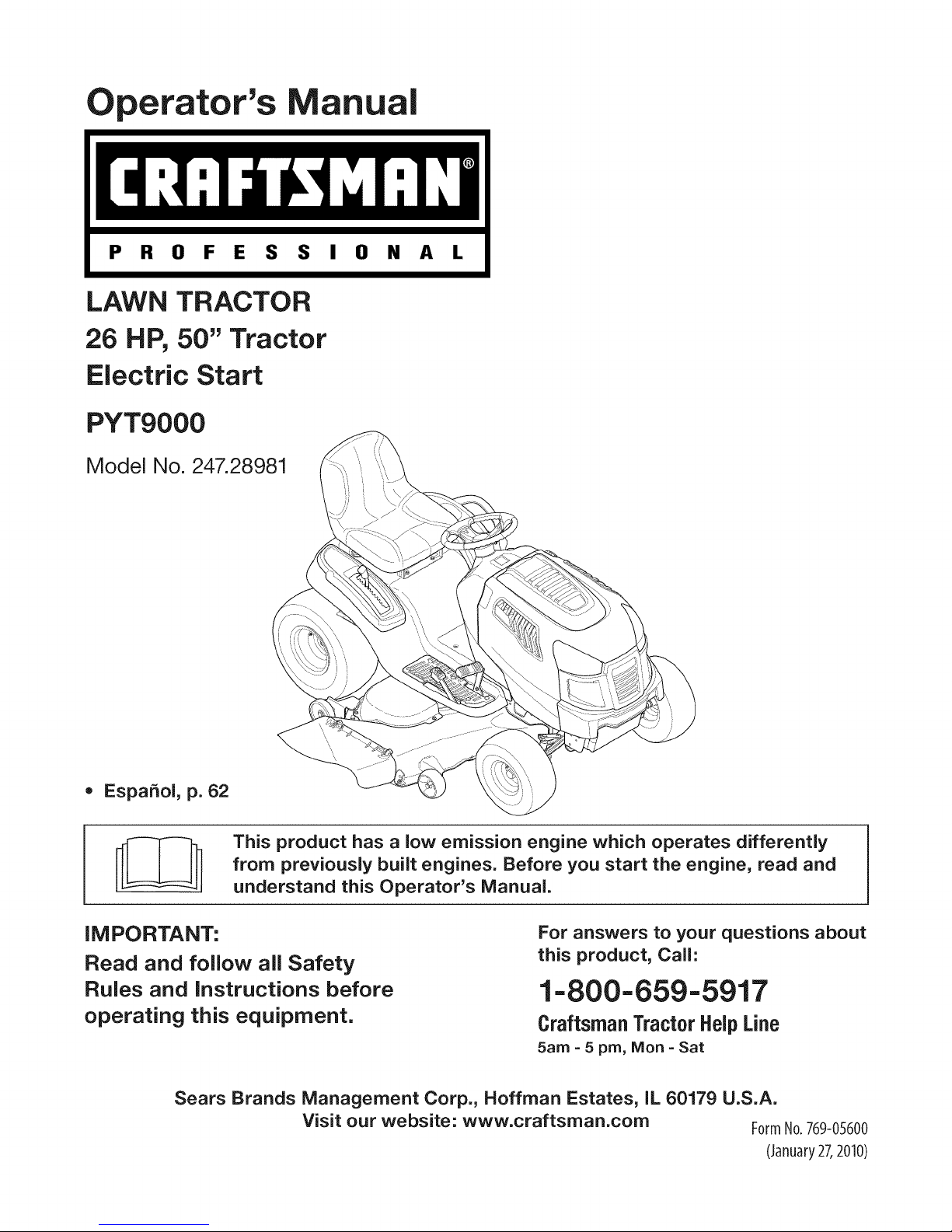
LAWN TRACTOR
26 HP, 50" Tractor
Electric Start
PYT9000
Model No. 247.28981
• EspaSol, p. 62
This product has a low emission engine which operates differently
from previously built engines. Before you start the engine, read and
understand this Operator's Manual.
iMPORTANT:
Read and follow all Safety
Rules and instructions before
operating this equipment.
Sears Brands Management Corp., Hoffman Estates, IL 60179 U.S.A.
Visit our website: www.craftsman.com FormNo.769-05600
For answers to your questions about
this product, Call:
1=800=659=5917
CraftsmanTractorHelpLine
5am = 5 pro, Mort =Sat
(January27,2010)
Page 2
Warranty Statement .......................................................... 2
Safety instructions ............................................................ 3
Safety Labels .................................................................... 9
Assembly ......................................................................... 10
Know your Lawn Mower .................................................. 13
Operation ........................................................................ 16
CRAFTSMAN PROFESSIONAL FULL WARRANTY
Whenoperatedand maintainedaccordingtoallsuppliedinstructions,ifany non-expendablepartof thisridingequipmentfailsduetoa defectin
materialor workmanshipwithintwo yearsfromthedateorpurchase,call1-800-659-5917toarrangeforfreein-homerepair.
Theframeandfrontaxlewill be repairedfreeofchargefor fiveyearsfromthe dateofpurchaseif defectiveinmaterialorworkmanship.
Alloftheabovewarrantycoverageappliesforonlyone yearfromthedateof purchaseifthis ridingequipmentiseverusedfor commercialor
rentalpurposes.
in allcases,if repairprovesimpossible,theridingequipmentwillbe replacedfreeofchargewiththesameoran equivalentmodel.
Thebatterywillbe replacedfreeofchargefor90 daysfromthe dateofpurchaseif defectiveinmaterialorworkmanship(ourtestingprovesthat it
willnotholda charge).
ThiswarrantycoversONLYdefectsin materialandworkmanship.SearswillNOTpayfor:
• Expendableitemsthatbecomewornduringnormaluse,includingbutnot limitedtoblades,sparkplugs,aircleaners,belts,andoil filters.
• Standardmaintenanceservicing,oilchanges,ortune-ups.
Tirereplacementor repaircausedbypuncturesfromoutsideobjects,suchasnails,thorns,stumps,orglass.
Tireor wheelreplacementor repairresultingfromnormalwear,accident,orimproperoperationormaintenance.
Repairsnecessarybecauseof operatorabuse,includingbutnot limitedtodamagecausedbytowingobjectsbeyondthecapabilityofthe
ridingequipment,impactingobjectsthatbendtheframeor crankshaft,or over-speedingtheengine.
• Repairsnecessarybecauseof operatornegligence,includingbutnotlimitedto,electricalandmechanicaldamagecausedbyimproper
storage,failureto usethepropergradeandamountofengineoil,failuretokeepthe deckclearofflammabledebris,orfailuretomaintainthe
ridingequipmentaccordingto theinstructionscontainedintheoperator'smanual.
• Engine(fuelsystem)cleaningorrepairscausedbyfueldeterminedto becontaminatedoroxidized(stale).in general,fuelshouldbeused
within30 daysof itspurchasedate.
Normaldeteriorationandwearoftheexteriorfinishes,orproductlabelreplacement.
Thiswarrantyappliesonlywhilethisproductiswithinthe UnitedStates.
Thiswarrantygivesyouspecificlegalrights,andyoumayalso haveotherrightswhichvaryfromstateto state.
Sears, Roebuckand Co., Hoffman Estates, IL 60179
GrossHP: 26
EngineOil: SAE30
Fuel: UnleadedGasoline
SparkPlug: Champion®RC12YC
Engine: Briggs& StrattonProfessionalSeries
© SearsBrands,LLC 2
Model Number
Serial Number
Dateof Purchase
Recordthe modelnumber,serialnumber,
anddateof purchaseabove.
Page 3
Thissymbolpointsout importantsafetyinstructionswhich,if not
followed,couldendangerthepersonalsafetyand/orpropertyof
yourselfandothers. Readandfollowall instructionsin thismanual
beforeattemptingtooperatethismachine.Failuretocomplywith
theseinstructionsmayresultin personalinjury.Whenyou seethis
symbol,HEEDITSWARNING!
Thismachinewasbuilttobeoperatedaccordingtothesafeopera-
tionpracticesinthis manual.Aswithanytypeof powerequipment,
carelessnessorerroron the partoftheoperatorcanresultinserious
injury.Thismachineiscapableofamputatingfingers,hands,toes
andfeetandthrowingdebris.Failuretoobservethe followingsafety
instructionscouldresultin seriousinjuryor death.
CALIFORNIA PROPOSITION 65
EngineExhaust,someof itsconstituents,andcertainvehicle
componentscontainoremitchemicalsknowntoStateof California
tocausecancerandbirthdefectsorotherreproductiveharm.
Batteryposts,terminals,and relatedaccessoriescontainleadand
leadcompounds,chemicalsknowntotheStateof Californiato
causecancerandreproductiveharm.Washhandsafterhandling.
GENERAL OPERATION
• Read,understand,andfollowall instructionson the machineand
in themanual(s)beforeattemptingtoassembleandoperate.
Keepthis manualina safeplaceforfutureand regularreference
andfororderingreplacementparts.
• Befamiliarwithall controlsandtheirproperoperation.Knowhow
tostopthemachineanddisengagethemquickly.
• Neverallowchildrenunder14yearsoldtooperatethismachine.
Children14yearsoldandovershouldreadandunderstandthe
operationinstructionsandsafetyrulesinthismanualandshould
betrainedandsupervisedbya parent.
• Neverallowadultstooperatethismachinewithoutproper
instruction.
• Tohelpavoidbladecontactor a thrownobjectinjury,keep
bystanders,helpers,childrenandpetsat least75feetfromthe
machinewhile itisin operation.Stopmachineifanyoneenters
thearea.
• Thoroughlyinspectthe areawheretheequipmentis tobe used.
Removeallstones,sticks,wire,bones,toys,andotherforeign
objectswhichcouldbe pickedupandthrownbythe blade(s).
Thrownobjectscancauseseriouspersonalinjury.
• Planyour mowingpatterntoavoiddischargeof materialtoward
roads,sidewalks,bystandersandthelike.Also,avoiddischarg-
ingmaterialagainstawallorobstructionwhichmaycause
dischargedmaterialto ricochetbacktowardthe operator.
Your Responsibility--Restrict theuseofthis powermachineto
personswhoread,understandandfollowthewarningsandinstruc-
tionsin thismanualandon the machine.
SAVE THESE INSTRUCTIONS!
• Alwayswearsafetyglassesorsafetygogglesduringoperation
andwhileperformingan adjustmentorrepairto protectyoureyes.
Thrownobjectswhichricochetcancauseseriousinjuryto the
eyes.
• Wearsturdy,rough-soledworkshoesandclose-fittingslacksand
shirts.Loosefittingclothesandjewelrycanbe caughtin movable
parts.Neveroperatethismachineinbarefeetorsandals.
• Beawareofthemowerandattachmentdischargedirectionand
do notpointit at anyone.Donotoperatethemowerwithoutthe
dischargecoverorentiregrasscatcherin its properplace.
Donot puthandsorfeetnearrotatingpartsor underthe cutting
deck.Contactwiththe blade(s)canamputatehandsandfeet.
A missingordamageddischargecovercancausebladecontact
or thrownobjectinjuries.
• Stoptheblade(s)whencrossinggraveldrives,walks,orroads
andwhilenotcuttinggrass.
• Watchfortrafficwhenoperatingnearorcrossingroadways.This
machineis notintendedforuseonanypublicroadway.
• Donot operatethemachinewhileundertheinfluenceof alcohol
or drugs.
• Mowonlyindaylightorgoodartificiallight.
Nevercarrypassengers.
• Disengageblade(s)beforeshiftingintoreverse.Backup slowly.
Alwayslookdownandbehindbeforeandwhilebackingtoavoida
back-overaccident.
3
Page 4
• Slowdownbeforeturning.Operatethemachinesmoothly.Avoid
erraticoperationandexcessivespeed.
Disengageblade(s),setparkingbrake,stopengineandwaituntil
theblade(s)cometoa completestopbeforeremovinggrass
catcher,emptyinggrass,uncloggingchute,removinganygrassor
debris,or makinganyadjustments.
Neverleavea runningmachineunattended.Alwaysturnoff
blade(s),setparkingbrake,stopengineandremovekeybefore
dismounting.
Useextracarewhenloadingorunloadingthemachineintoa
trailerortruck.Thismachineshouldnotbedrivenupor down
ramp(s),becausethemachinecouldtip over,causingserious
personalinjury.Themachinemustbe pushedmanuallyon
ramp(s)to loador unloadproperly.
Mufflerandenginebecomehotandcancausea burn.Donot
touch.
Checkoverheadclearancescarefullybeforedrivingunderlow
hangingtree branches,wires,dooropeningsetc.,wherethe
operatormaybestruckor pulledfromthemachine,whichcould
resultinseriousinjury.
Disengageallattachmentclutchesanddepressthebrakepedal
completelybeforeattemptingto startengine.
Yourmachineisdesignedto cutnormalresidentialgrassofa
heightnomorethan10".Donotattemptto mowthroughunusually
tall,drygrass(e.g.,pasture)orpiles ofdryleaves.Drygrassor
leavesmaycontacttheengineexhaustand/orbuilduponthe
mowerdeckpresentinga potentialfirehazard.
Useonlyaccessoriesandattachmentsapprovedfor this machine
bythe machinemanufacturer.Read,understandandfollowall
instructionsprovidedwiththe approvedaccessoryorattachment.
Fora list of approvedaccessoriesandattachments,call 1-800-
659-5917.
Dataindicatesthatoperators,age60yearsandabove,are
involvedin a largepercentageofridingmower-relatedinjuries.
Theseoperatorsshouldevaluatetheirabilityto operatetheriding
mowersafelyenoughto protectthemselvesandothersfrom
seriousinjury.
If situationsoccurwhicharenotcoveredinthismanual,usecare
andgoodjudgment.Contact1-800-659-5917forinformationand
assistance.
SLOPE OPERATION
Slopesarea majorfactorrelatedtolossof controlandtip-over
accidentswhichcanresultinsevereinjuryor death.Allslopesrequire
extracaution.Ifyoucannotbackuptheslopeor if youfeeluneasyon
it, do notmowit.
Foryoursafety,usetheSlopeGuideincludedaspartofthis manual
to measureslopesbeforeoperatingthismachineona slopedorhilly
area.Iftheslopeisgreaterthan15degreesasshownonthe Slope
Guide,do notoperatethis machineonthatareaor seriousinjurycould
result.
Do:
o
Mowupanddownslopes,notacross.Exerciseextremecaution
whenchangingdirectionon slopes.
• Watchforholes,ruts,bumps,rocks,orotherhiddenobjects.
Uneventerraincouldoverturnthe machine.Tallgrasscanhide
obstacles.
Useslowspeed.Choosea lowenoughspeedsettingsothat
youwill nothaveto stopor shiftwhileon the slope.Tiresmay
losetractionon slopeseventhoughthe brakesarefunctioning
properly.Alwayskeepmachinein gearwhengoingdownslopes
totakeadvantageof enginebrakingaction.
• Followthe manufacturer'srecommendationsforwheelweights
or counterweightstoimprovestability.Forrecommendations,call
1-800-659-5917.
• Useextracarewithgrasscatchersor otherattachments.These
canchangethestabilityofthe machine.
Keepallmovementontheslopesslowandgradual.Donotmake
suddenchangesinspeedor direction.Rapidengagementor
brakingcouldcausethefrontofthemachinetolift andrapidlyflip
overbackwardswhichcouldcauseseriousinjury.
• Avoidstartingorstoppingona slope.Iftireslosetraction,disen-
gagetheblade(s)andproceedslowlystraightdownthe slope.
DoNot:
• Donot turnon slopesunlessnecessary;then,turnslowlyand
graduallydownhill,ifpossible.
• Donot mowneardrop-offs,ditchesor embankments.Themower
couldsuddenlyturnoverifa wheelis overtheedgeofa cliff,
ditch,or ifan edgecavesin.
• Donot try tostabilizethemachineby puttingyourfooton the
ground.
• Donot usea grasscatcheronsteepslopes.
• Donot mowon wetgrass.Reducedtractioncouldcausesliding.
• Donot attempttocoastdownhill.Over-speedingmaycausethe
operatortolosecontrolofthe machineresultinginseriousinjury
or death.
• Donot towheavypull behindattachments(e.g.loadeddumpcart,
lawnroller,etc.)on slopesgreaterthan5 degrees.Whengoing
downhill,theextraweighttendstopushthe tractorandmay
causeyouto loosecontrol.(e.g.tractormayspeedup,braking
and steeringabilityare reduced,attachmentmayjack-knifeand
causetractorto overturn).
4
Page 5
CHILDREN
Tragicaccidentscanoccuriftheoperatorisnotalerttothepresence
ofchildren.Childrenareoftenattractedtothe machineandthe mowing
activity.Theydonotunderstandthedangers.Neverassumethat
childrenwillremainwhereyoulastsawthem.
• Keepchildrenoutofthe mowingareaand inwatchfulcareofa
responsibleadultotherthantheoperator.
• Bealertandturnmachineoff ifa childentersthearea.
• Beforeandwhilebacking,lookbehindanddownfor small
children.
Nevercarrychildren,evenwiththeblade(s)shutoff.Theymay
falloffandbe seriouslyinjuredorinterferewithsafemachine
operation.
• Useextremecarewhenapproachingblindcorners,doorways,
shrubs,treesorotherobjectsthatmayblockyourvisionofa child
whomayrunintothe machine.
Toavoidback-overaccidents,alwaysdisengagethe cutting
blade(s)beforeshiftingintoReverse.Ifequipped,the"Reverse
CautionMode"(bladesoperatewhilemachineridesinreverse)
shouldnotbe usedwhenchildrenor othersarearound.
Keepchildrenawayfromhotor runningengines.Theycansuffer
burnsfroma hotmuffler.
• Removekeywhenmachineisunattendedtopreventunauthorized
operation.
Neverallowchildrenunder14yearsofagetooperatethismachine.
Children14andovershouldreadandunderstandthe instructionsand
safeoperationpracticesinthismanualandon the machineandshould
betrainedandsupervisedbyan adult.
TOWING
Towonlywitha machinethathasa hitchdesignedfortowing.Do
notattachtowedequipmentexceptatthehitchpoint.
Followthemanufacturersrecommendationforweightlimitsfor
towedequipmentandtowingonslopes.For recommendations,
call1-800-659-5917.
Neverallowchildrenor othersinoron towedequipment.
Onslopes,theweightof thetowedequipmentmaycauselossof
tractionandlossof control.
Alwaysuseextracautionwhentowingwitha machinecapableof
makingtightturns(e.g."zero-turn"ride-onmower). Makewide
turnstoavoidjack-knifing.
Travelslowlyandallowextradistanceto stop.
Donotcoastdownhill.
SERVICE
SafeHandlingof Gasoline
Toavoidpersonalinjuryorpropertydamageuseextremecarein
handlinggasoline.Gasolineisextremelyflammableandthevaporsare
explosive.Seriouspersonalinjurycanoccurwhengasolineisspilled
on yourselforyourclotheswhichcanignite.Washyourskinand
changeclothesimmediately.
• Useonlyanapprovedgasolinecontainer.
Neverfill containersinsidea vehicleoron a truckortrailerbed
witha plasticliner.Alwaysplacecontainerson thegroundaway
fromyourvehiclebeforefilling.
Whenpractical,removegas-poweredequipmentfromthe truck
or trailerandrefueliton theground.Ifthis isnotpossible,then
refuelsuchequipmentona trailerwithaportablecontainer,rather
thanfroma gasolinedispensernozzle.
Keepthenozzleincontactwiththerim ofthefueltankor
containeropeningat all timesuntilfuelingiscomplete.Donotuse
a nozzlelock-opendevice.
Extinguishall cigarettes,cigars,pipesandothersourcesof
ignition.
• Neverfuel machineindoors.
Neverremovegascapor addfuelwhilethe engineis hotorrun-
ning.Allowengineto coolat leasttwominutesbeforerefueling.
Neveroverfillfueltank. Filltanktono morethan1/2inchbelow
bottomoffillernecktoallowspaceforfuelexpansion.
• Replacegasolinecapandtightensecurely.
• Ifgasolineisspilled,wipeitoff theengineandequipment.Move
machineto anotherarea.Wait5 minutesbeforestartingthe
engine.
• To reducefirehazards,keepmachinefreeofgrass,leaves,or
otherdebrisbuild-up.Cleanup oilor fuelspillageandremoveany
fuelsoakeddebris.
• Neverstorethemachineorfuelcontainerinsidewherethereisan
openflame,sparkor pilotlightas ona waterheater,spaceheater,
furnace,clothesdryeror othergasappliances.
Allowa machineto coolat leastfiveminutesbeforestoring.
Page 6
GeneralService
• Neverrunanengineindoorsorinapoorlyventilatedarea.Engine
exhaustcontainscarbonmonoxide,anodorless,anddeadlygas.
• Beforecleaning,repairing,orinspecting,makecertainthe
blade(s)andallmovingpartshavestopped.Disconnectthespark
plugwireandgroundagainsttheenginetopreventunintended
starting.
• Periodicallychecktomakesurethebladescometocomplete
stopwithinapproximately(5)fivesecondsafteroperatingthe
bladedisengagementcontrol.Ifthebladesdonotstopwithinthe
thistimeframe,yourmachineshouldbeservicedprofessionally
byaSearsorotherqualifiedservicedealer.
• Checkbrakeoperationfrequentlyasitissubjectedtowearduring
normaloperation.Adjustandserviceasrequired.
• Checktheblade(s)andenginemountingboltsatfrequent
intervalsforpropertightness.Also,visuallyinspectblade(s)
fordamage(e.g.,excessivewear,bent,cracked).Replacethe
blade(s)withtheoriginalequipmentmanufacturer's(O.E.M.)
blade(s)only,listedinthismanual.Useofpartswhichdonot
meettheoriginalequipmentspecificationsmayleadtoimproper
performanceandcompromisesafety!
• Mowerbladesaresharp.Wrapthebladeorweargloves,anduse
extracautionwhenservicingthem.
• Keepallnuts,bolts,andscrewstighttobesuretheequipmentis
insafeworkingcondition.
• Nevertamperwiththesafetyinterlocksystemorothersafety
devices.Checktheirproperoperationregularly.
• Afterstrikingaforeignobject,stopthe engine,disconnectthe
sparkplugwire(s)andgroundagainsttheengine.Thoroughly
inspectthemachineforanydamage.Repairthedamagebefore
startingandoperating.
• Neverattemptto makeadjustmentsor repairstothemachine
whilethe engineis running.
• Grasscatchercomponentsandthe dischargecoveraresubject
towearanddamagewhichcouldexposemovingpartsor allow
objectsto bethrown.Forsafetyprotection,frequentlycheck
componentsand replaceimmediatelywithoriginalequipment
manufacturer's(O.E.M.)partsonly,listedinthis manual.Useof
partswhichdo not meettheoriginalequipmentspecificationsmay
leadtoimproperperformanceandcompromisesafety!
• Donot changetheenginegovernorsettingsorover-speedthe
engine.Thegovernorcontrolsthe maximumsafeoperatingspeed
ofthe engine.
Maintainor replacesafetyandinstructionlabels,as necessary.
• Observeproperdisposallawsandregulationsforgas,oil,etc.to
protecttheenvironment.
• Accordingtothe ConsumerProductsSafetyCommission(CPSC)
andthe U.S.EnvironmentalProtectionAgency(EPA),thisproduct
hasanAverageUsefulLifeof seven(7)years,or 270hours
ofoperation.AttheendoftheAverageUsefulLife,buy anew
machineor havethemachineinspectedannuallybya Searsor
otherqualifiedservicedealerto ensurethatall mechanicaland
safetysystemsareworkingproperlyandnotwornexcessively.
Failuretodosocanresultinaccidents,injuriesor death.
DO NOT MODIFY ENGINE
Toavoid seriousinjuryor death,do notmodifyengineinanyway.
Tamperingwiththe governorsettingcanleadtoa runawayengineand
causeittooperateat unsafespeeds.Nevertamperwithfactorysetting
ofenginegovernor.
NOTICE REGARDING EMISSIONS
Engineswhicharecertifiedto complywithCaliforniaandfederal
EPAemissionregulationsfor SORE(SmallOffRoadEquipment)are
certifiedto operateonregularunleadedgasoline,andmayinclude
thefollowingemissioncontrolsystems:EngineModification(EM)and
ThreeWayCatalyst(TWO)if so equipped.
SPARK ARRESTOR
Thismachineisequippedwithan internalcombustionengineand
shouldnotbe usedonor nearanyunimprovedforest-covered,
brushcoveredorgrass-coveredlandunlesstheengine'sexhaust
systemisequippedwitha sparkarrestermeetingapplicablelocalor
statelaws(if any).
Ifa sparkarresteris used,it shouldbe maintainedin effectiveworking
orderbytheoperator.IntheStateof Californiatheaboveis required
bylaw (Section4442of the CaliforniaPublicResourcesCode).Other
statesmayhavesimilarlaws.Federallawsapplyonfederallands.
A sparkarresterforthemufflerisavailablethroughyournearestSears
PartsandRepairServiceCenter.
6
Page 7
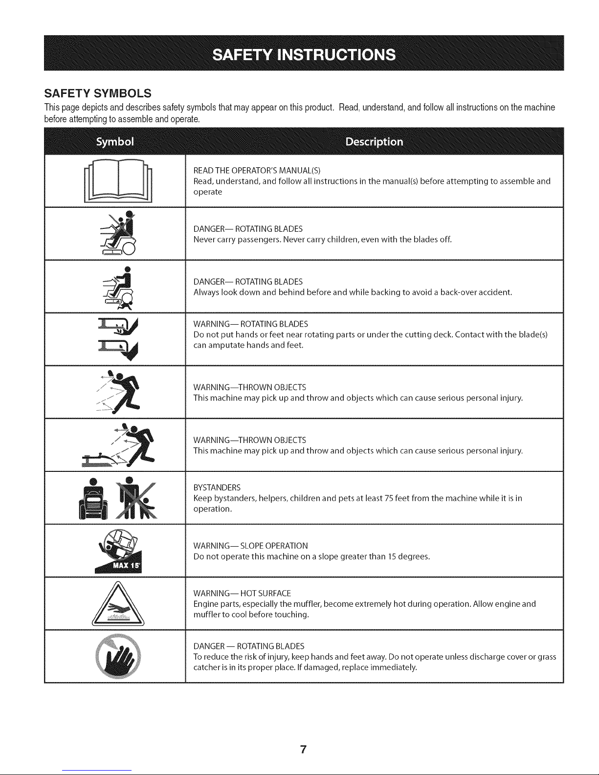
SAFETY SYMBOLS
Thispagedepictsanddescribessafetysymbolsthatmayappearonthis product.Read,understand,andfollowallinstructionson the machine
beforeattemptingtoassembleandoperate.
READ THE OPERATOR'S MANUAL(S)
Read, understand, and follow all instructions in the manual(s) before attempting to assemble and
operate
DANGER-- ROTATING BLADES
Never carry passengers. Never carry children, even with the blades off.
0
DANGER-- ROTATING BLADES
Always look down and behind before and while backing to avoid a back-over accident.
WARNING-- ROTATING BLADES
Do not put hands or feet near rotating parts or under the cutting deck. Contact with the blade(s)
can amputate hands and feet.
A
WARNING--THROWN OBJECTS
This machine may pick up and throw and objects which can cause serious personal injury.
WARNING--THROWN OBJECTS
This machine may pick up and throw and objects which can cause serious personal injury.
BYSTANDERS
Keep bystanders, helpers, children and pets at least 75 feet from the machine while it is in
operation.
WARNING-- SLOPE OPERATION
Do not operate this machine on a slope greater than 15 degrees.
WARNING-- HOT SURFACE
Engine parts, especially the muffler, become extremely hot during operation. Allow engine and
muffler to cool before touching.
DANGER-- ROTATING BLADES
To reduce the risk of injury, keep hands and feet away. Do not operate unless discharge cover or grass
catcher is in its proper place. If damaged, replace immediately.
7
Page 8
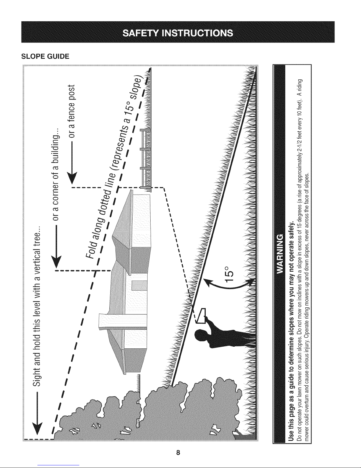
SLOPE GUIDE
O
m
}=,==
}====
G.)
1>
_==
r_)
O
O
='-!
O
Nm
O
l
l
l
l
l
l
l
%
l
l
l
l
l
l
l
l
l
0
I
I
o
(I)
E
o
o
L(3 0
r..- o
c
cz co
Q
o
_E
oo
_==
I
0
c-
c_
c-
.__
U3
I
I
I
I
0
o_
C2_ c__
d °
o
R_
X_
o o
8
Page 9
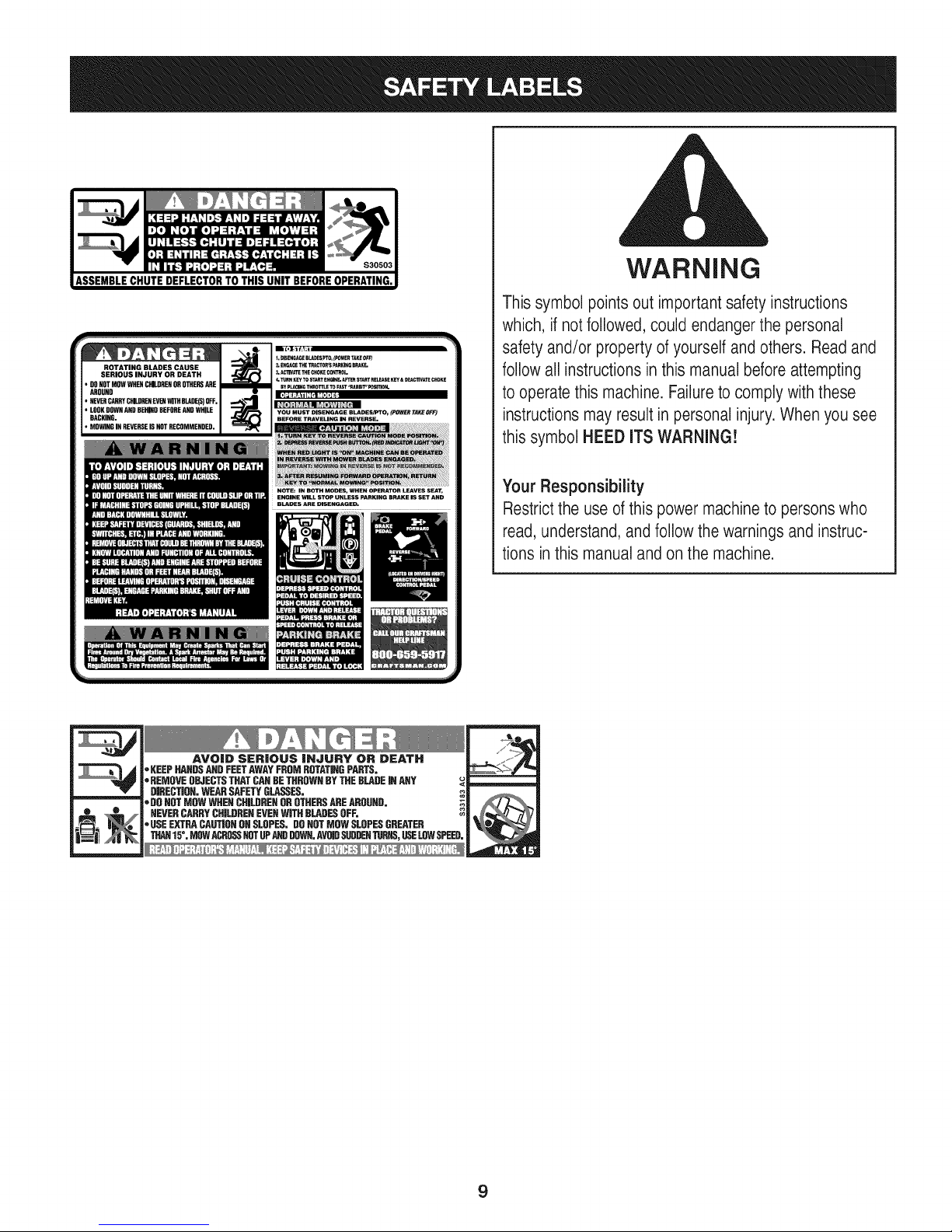
ROTATING BLADES CAUSE
SERIOUS INJURY OR DEATH
• DONOTMOWWHENORILORENOROTHERSARE
AROUND
• NEVERCARRyCHI_DREGEVENWITHBlADE(S)OFF,
• LOOKGOWNAND 8EHIND8EFOREANDWHILE
BACKING,
• MOWINGINREVERSEISNOTRECOMMENDED,
WARNING
Thissymbol points out importantsafety instructions
which, if not followed,could endanger the personal
safety and/or property ofyourselfand others. Readand
followall instructionsin this manual before attempting
to operatethis machine. Failureto comply with these
instructionsmay result in personalinjury.Whenyou see
this symbol HEED ITSWARNING!
m _f
NOTE: IN BOTH MODES, WHEN OPERATOR LEAVES SEAT,
ENGINE WILL 5TOp UNLESS pARKING BRAKE IS SET AND
BLADES ARE DISENGAGED,
*KEEP HANDSANDFEETAWAYFROMROTATINGPARTS,
. REMOVEOBJECTSTHATCANDETHROWNBYTHEBLADEiNANY
*DO NOTMOWWHENCHILDRENDROTHERSAREAROUND,
oUSEEXTRACAUTIONOHSLOPES,DONOTMOWSLOPESGREATER
AVOID SERIOUS iNJURY OR DEATH
DiRECTiON,WEARSAFETYGLASSES, ,_
NEVERCARRYCHILDRENEVENWITHBLADESOFF, ?_
THAN15=,MOWACROSS_T UPANDDOWN,AVOIDSUDDENTURNS,USELOWSPEED,
Your Responsibility
Restrictthe use ofthis power machineto personswho
read, understand,and followthe warnings and instruc-
tions inthis manualand on the machine.
9
Page 10
TRACTOR SET-UP
Moving The Tractor Manually
Yourtractor'stransmissionisequippedwitha hydrostaticreliefvalve
foroccasionswhenitis necessaryto movethe tractormanually.Open-
ingthisvalvepermitsthefluidin the transmissionto bypassitsnormal
route,allowingthereartiresto "freewheel."Toopenthehydrostatic
reliefvalve,proceedasfollows:
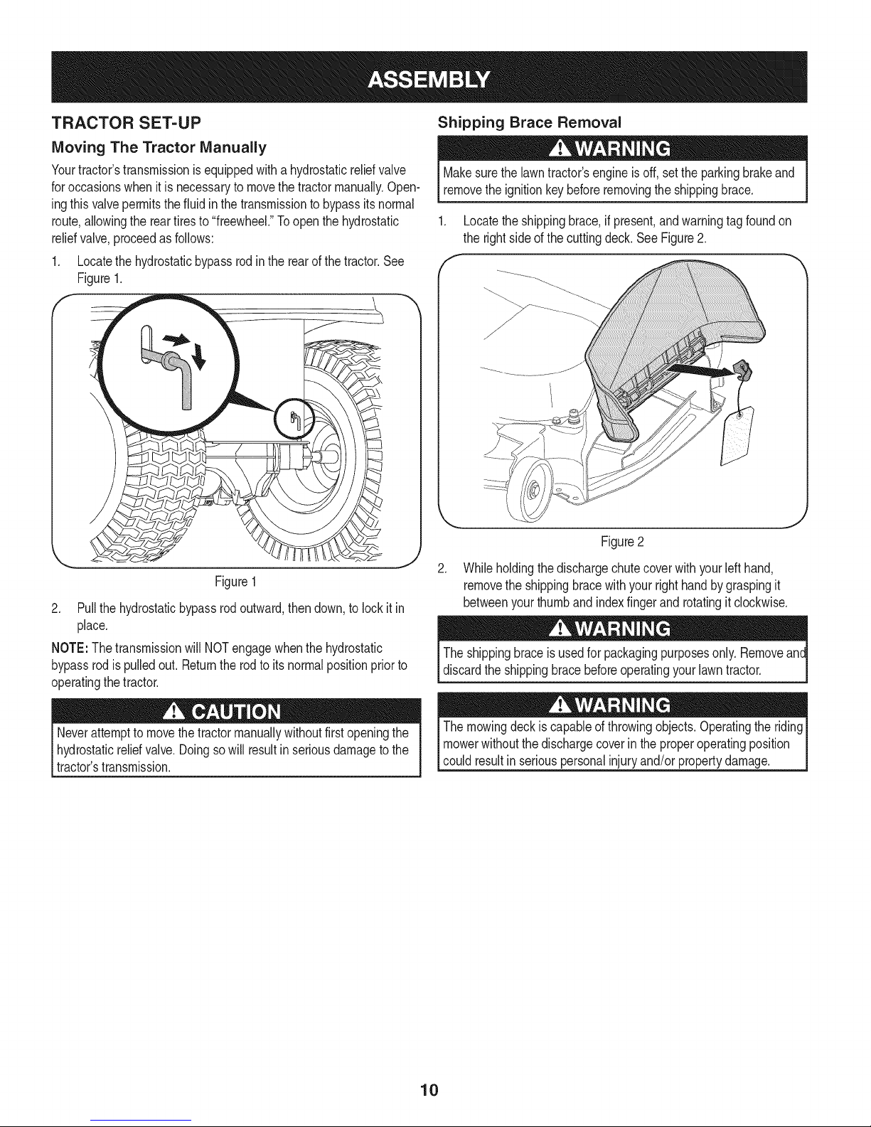
1. Locatethehydrostaticbypassrodintherearofthetractor.See
Figure1.
Shipping Brace Removal
Makesurethe lawntractor'sengineisoff,setthe parkingbrakeand
removethe ignitionkeybeforeremovingtheshippingbrace.
1. Locatetheshippingbrace,ifpresent,andwarningtagfoundon
the rightsideofthecuttingdeck.SeeFigure2.
Figure1
2. Pullthehydrostaticbypassrodoutward,thendown,tolockit in
place.
NOTE:The transmissionwillNOTengagewhenthehydrostatic
bypassrodis pulledout. Returnthe rodto itsnormalpositionpriorto
operatingthetractor.
Neverattemptto movethetractormanuallywithoutfirstopeningthe
hydrostaticreliefvalve.Doingsowillresultinseriousdamagetothe
tractor'stransmission.
Figure2
.
Whileholdingthe dischargechutecoverwithyourlefthand,
removethe shippingbracewithyourrighthandbygraspingit
betweenyourthumband indexfingerand rotatingitclockwise.
Theshippingbraceis usedforpackagingpurposesonly.Removeant
discardtheshippingbracebeforeoperatingyourlawntractor.
Themowingdeckis capableofthrowingobjects.Operatingthe riding
mowerwithoutthedischargecoverin theproperoperatingposition
couldresultin seriouspersonalinjuryand/orpropertydamage.
10
Page 11
CONNECTING THE BATTERY CABLES Checking Tire Pressure
Batteryposts,terminals,andrelatedaccessoriescontainleadand
leadcompounds,chemicalsknowntotheStateofCaliforniato cause
cancerandreproductiveharm.Washhandsafterhandling.
Whenattachingbatterycables,alwaysconnectthe POSiTiVE(Red)
wireto its terminalfirst,followedbythe NEGATIVE(Black)wire.
Toconnectthebatterycables,proceedasfollows:
NOTE:The positivebatteryterminalismarkedPositive(+).The
negativebatteryterminalismarkedNegative(-).
1. Removetheplasticcover,if present,fromthepositive(+)battery
terminalandattachthe redcable tothepositive(+)battery
terminalwiththebolt andhex nut.SeeFigure3.
Donot overinflatetires.Checksidewalloftiresformaximumpsi.
Equaltire pressureshouldbemaintainedat all times.
Thetiresonyourtractormaybeoverinflatedforshippingpurposes.
Reducethe tirepressurebeforeoperatingthetractor.Checksidewall
oftiresformaximumpsi.
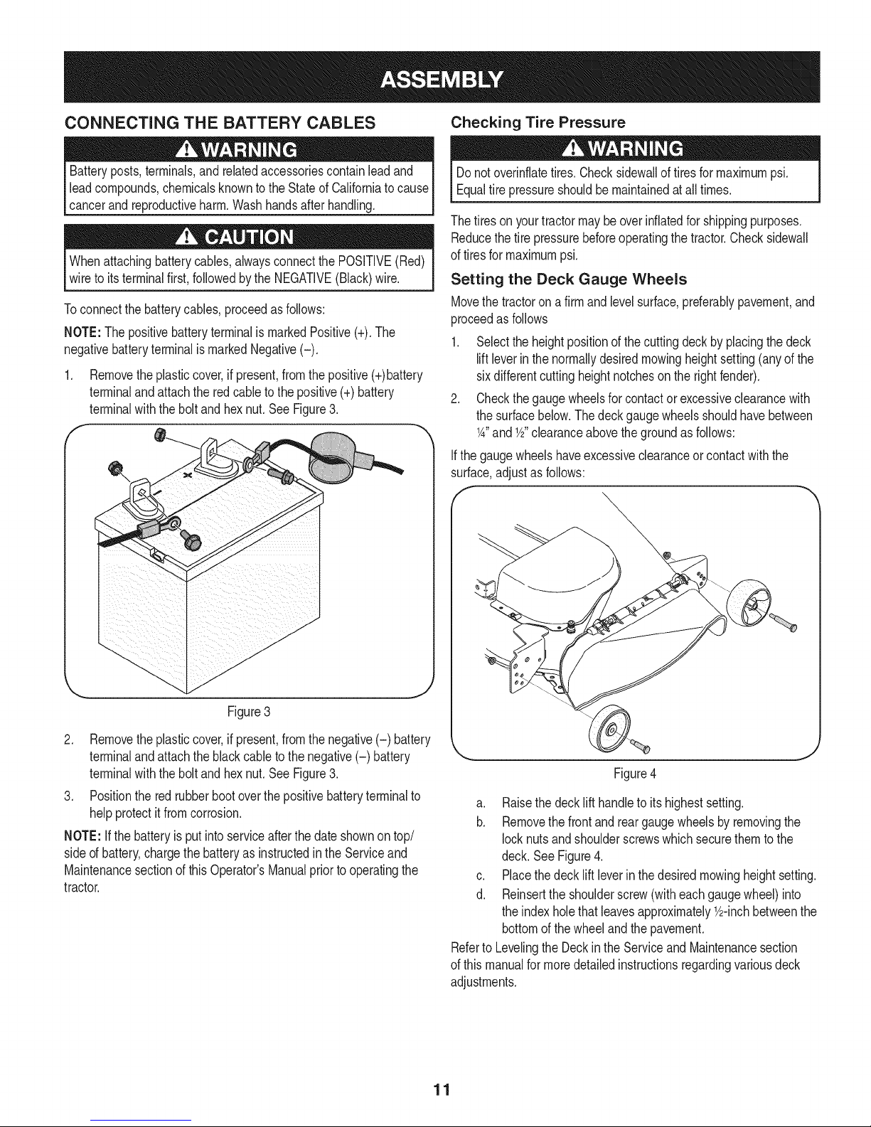
Setting the Deck Gauge Wheels
Movethe tractoron afirmand levelsurface,preferablypavement,and
proceedas follows
1. Selecttheheightpositionofthecuttingdeckby placingthedeck
liftleverin thenormallydesiredmowingheightsetting(anyofthe
sixdifferentcuttingheightnotchesontherightfender).
2. Checkthegaugewheelsfor contactor excessiveclearancewith
thesurfacebelow.Thedeckgaugewheelsshouldhavebetween
1A"and1/2"clearanceabovethegroundasfollows:
Ifthegaugewheelshaveexcessiveclearanceorcontactwiththe
surface,adjustas follows:
f
Figure3
2. Removetheplasticcover,if present,fromthenegative(-) battery
terminalandattachtheblackcabletothe negative(-) battery
terminalwiththebolt andhex nut.SeeFigure3.
3. Positionthe redrubberbootoverthepositivebatteryterminalto
helpprotectit fromcorrosion.
NOTE:Ifthebatteryisputintoserviceafterthedateshownontop/
sided battery,chargethebatteryasinstructedintheServiceand
Maintenancesectionofthis Operator'sManualpriortooperatingthe
tractor.
Figure4
a. Raisethe decklift handleto its highestsetting.
b. Removethefrontandreargaugewheelsbyremovingthe
locknutsandshoulderscrewswhichsecurethemto the
deck.SeeFigure4.
c. Placethedecklift leverinthedesiredmowingheightsetting.
d. Reinsertthe shoulderscrew(witheachgaugewheel)into
theindexholethatleavesapproximately_/2-inchbetweenthe
bottomofthewheelandthe pavement.
Referto Levelingthe Deckin the Serviceand Maintenancesection
ofthis manualformoredetailedinstructionsregardingvariousdeck
adjustments.
11
Page 12
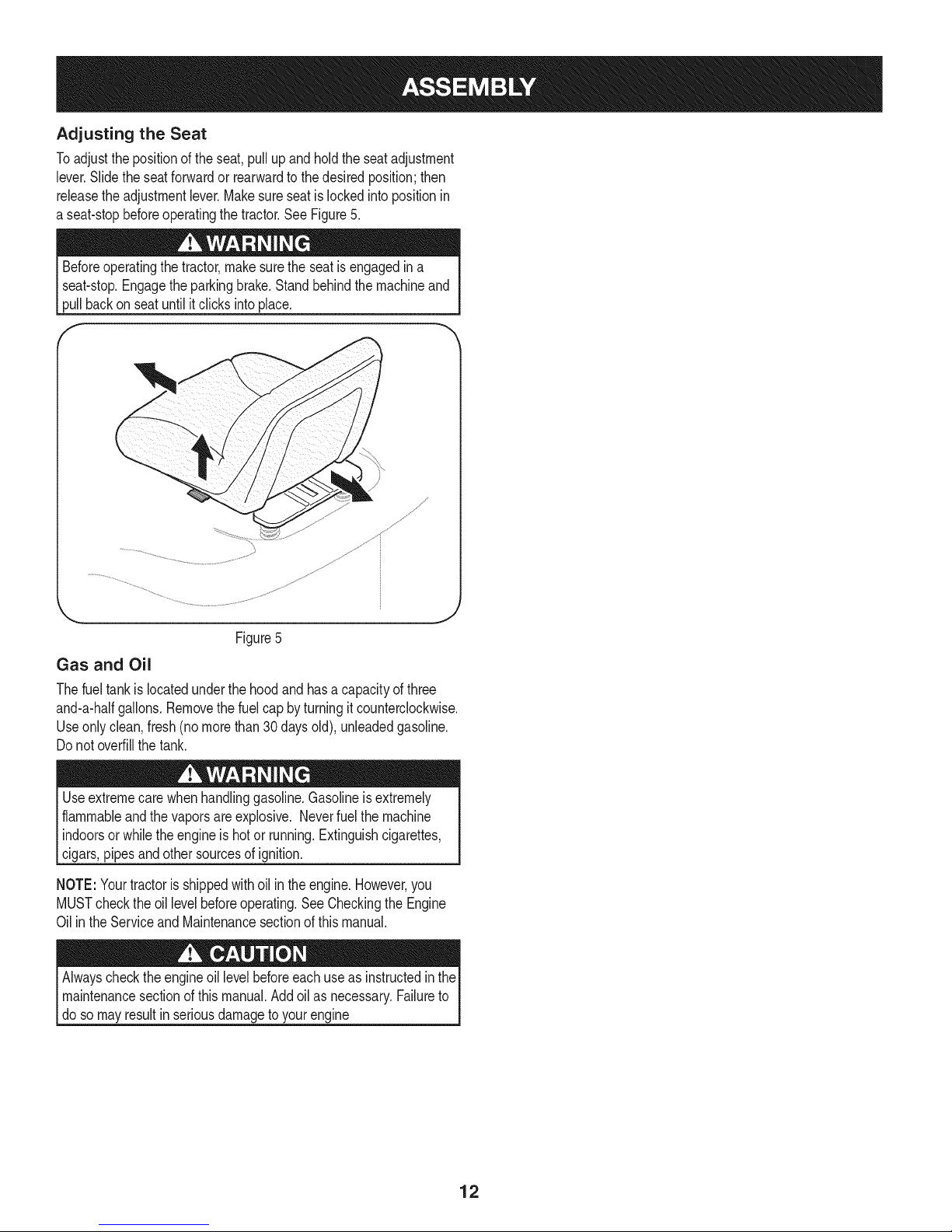
Adjusting the Seat
Toadjustthe positionoftheseat,pullup andholdtheseatadjustment
lever.Slidetheseatforwardor rearwardtothedesiredposition;then
releasetheadjustmentlever.Makesureseatislockedintopositionin
a seat-stopbeforeoperatingthe tractor.SeeFigure5.
Beforeoperatingthe tractor,makesuretheseatisengagedina
seat-stop.Engagethe parkingbrake.Standbehindthe machineand
pullbackon seatuntilitclicksintoplace.
J
Figure5
Gas and Oil
Thefuel tankis locatedunderthehoodandhasa capacityofthree
and-a-halfgallons.Removethefuelcap by turningitcounterclockwise.
Useonlyclean,fresh(no morethan30daysold), unleadedgasoline.
Donotoverfillthetank.
Useextremecarewhenhandlinggasoline.Gasolineis extremely
flammableandthevaporsareexplosive.Neverfuelthemachine
indoorsorwhiletheengineishotor running.Extinguishcigarettes,
cigars,pipesandothersourcesofignition.
NOTE:Yourtractorisshippedwithoil in theengine.However,you
MUSTchecktheoil levelbeforeoperating.SeeCheckingtheEngine
Oilin the ServiceandMaintenancesectionofthis manual.
Alwayschecktheengineoil levelbeforeeachuseas instructedinthe
maintenancesectionofthismanual.Addoilas necessary.Failureto
dosomayresultin seriousdamagetoyourengine
12
Page 13
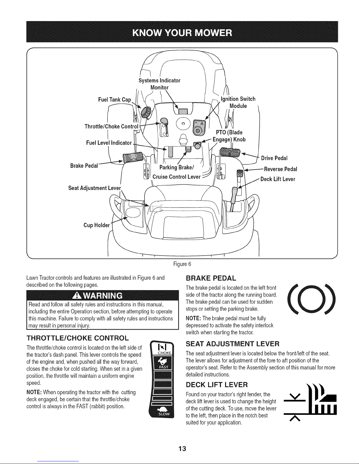
f
SystemsIndicator
Monitor
FuelTank Cap
Throttle/ChokeControl_
I
FuelLevelIndicator
BrakePedal
SeatAdjustmentLever
Cup Holder"
ParkingBrake/
Cruise Control Lever
Ignition Switch
Module
PTO(Blade
Knob
DrivePedal
Pedal
Lift Lever
\
Figure6
LawnTractorcontrolsandfeaturesareillustratedinFigure6and
describedon thefollowingpages.
Readandfollowallsafetyrulesandinstructionsinthismanual,
includingtheentireOperationsection,beforeattemptingtooperate
this machine.Failuretocomplywithall safetyrulesandinstructions
mayresultin personalinjury.
THROTTLE/CHOKE CONTROL
Thethrottle/chokecontrolis locatedon theleftsideof
thetractor'sdashpanel.Thislevercontrolsthespeed
ofthe engineand,whenpushedallthewayforward,
closesthechokeforcoldstarting.Whensetin agiven
position,thethrottlewillmaintaina uniformengine
speed.
NOTE:Whenoperatingthetractorwiththe cutting
deckengaged,becertainthatthethrottle/choke
controlisalwaysintheFAST(rabbit)position.
BRAKE PEDAL
Thebrakepedalis locatedon theleftfront
sideof thetractoralongthe runningboard.
Thebrakepedalcanbeusedfor sudden
stopsorsettingtheparkingbrake.
NOTE:Thebrakepedalmustbefully
depressedto activatethesafetyinterlock
switchwhenstartingthetractor.
SEAT ADJUSTMENT LEVER
Theseatadjustmentleveris locatedbelowthefront!leftof theseat.
Theleverallowsforadjustmentoftheforeto aft positionofthe
operator'sseat.RefertotheAssemblysectionofthismanualformore
detailedinstructions.
DECK LiFT LEVER
Foundonyour tractor'srightfender,the V
decklift leverisusedto changetheheight
ofthe cuttingdeck.To use,movethelever
tothe left, thenplaceinthenotchbest A
suitedforyour application.
13
Page 14
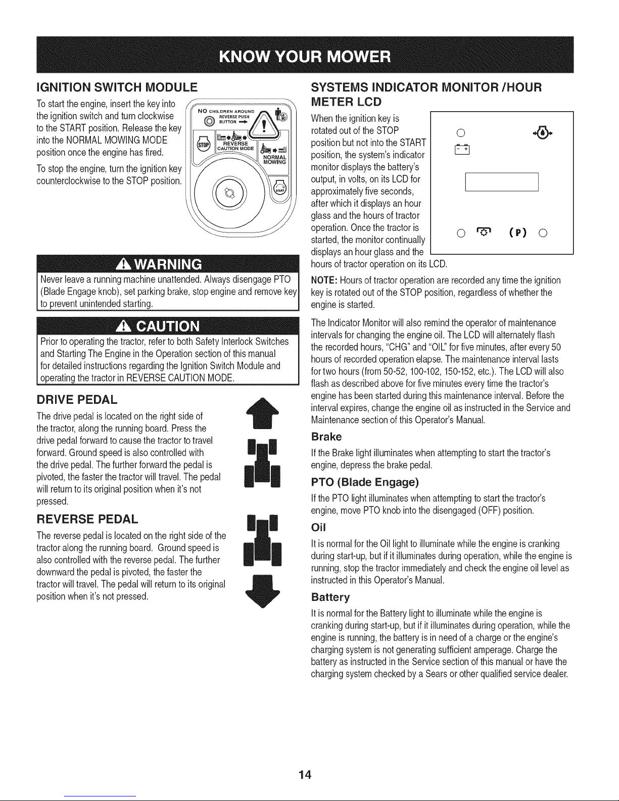
iGNiTiON SWITCH MODULE
Tostart theengine,insertthe keyinto
theignitionswitchand turnclockwise
tothe STARTposition.Releasethekey
intothe NORMALMOWINGMODE
positiononcethe enginehasfired.
Tostoptheengine,turntheignitionkey
counterclockwiseto the STOPposition.
(BladeEngageknob),setparkingbrake,stopengineandremove
topreventunintendedstarting.
Priortooperatingthetractor,referto bothSafetyInterlockSwitches
andStartingTheEngineinthe Operationsectionofthismanual
fordetailedinstructionsregardingthe IgnitionSwitchModuleand
[operatngthetractor n REVERSECAUTONMODE.
SUTTON
REVERSE PUSH
DRIVE PEDAL
Thedrivepedalislocatedon therightsideof
thetractor,alongthe runningboard.Pressthe
drivepedalforwardto causethe tractortotravel
forward.Groundspeedisalsocontrolledwith
thedrive pedal.Thefurtherforwardthe pedalis
pivoted,thefasterthetractorwilltravel.Thepedal
willreturnto itsoriginalpositionwhenit'snot
pressed.
REVERSE PEDAL
Thereversepedalislocatedontherightsideof the
tractoralongthe runningboard. Groundspeedis
alsocontrolledwiththe reversepedal.Thefurther
downwardthe pedalispivoted,thefasterthe
tractorwilltravel.Thepedalwillreturnto itsoriginal
positionwhenit'snotpressed.
|
SYSTEMS INDICATOR MONITOR/HOUR
METER LCD
Whenthe ignitionkeyis
rotatedout oftheSTOP
positionbutnot intotheSTART
position,thesystem'sindicator
monitordisplaysthebattery's
output,involts,on itsLCDfor
approximatelyfiveseconds,
afterwhichitdisplaysanhour
glassandthehoursof tractor
operation.Oncethetractoris
started,themonitorcontinually
displaysanhourglassandthe
hoursof tractoroperationonitsLCD.
NOTE:Hoursof tractoroperationarerecordedanytimetheignition
keyisrotatedout oftheSTOPposition,regardlessof whetherthe
engineisstarted.
TheIndicatorMonitorwillalso remindtheoperatorofmaintenance
intervalsforchangingtheengineoil.The LCDwill alternatelyflash
the recordedhours,"CHG"and"OIL."for fiveminutes,afterevery50
hoursof recordedoperationelapse.Themaintenanceintervallasts
fortwo hours(from50-52,100-102,150-152,etc.).TheLCDwillalso
flashasdescribedaboveforfiveminuteseverytimethe tractor's
enginehasbeenstartedduringthismaintenanceinterval.Beforethe
intervalexpires,changetheengineoilasinstructedintheServiceand
Maintenancesectionof thisOperator'sManual.
Brake
ifthe Brakelightilluminateswhenattemptingtostart thetractor's
engine,depressthebrakepedal.
PTO (Blade Engage)
IfthePTOlight illuminateswhenattemptingto startthetractor's
engine,movePTOknobinto thedisengaged(OFF)position.
Oil
ItisnormalfortheOillightto illuminatewhiletheengineiscranking
duringstart-up,butifit illuminatesduringoperation,whiletheengineis
running,stopthetractorimmediatelyandchecktheengineoil levelas
instructedinthis Operator'sManual.
Battery
Itis normalfortheBatterylighttoilluminatewhilethe engineis
crankingduringstart-up,butifitilluminatesduringoperation,whilethe
engineisrunning,thebatteryis inneedof a chargeortheengine's
chargingsystemisnotgeneratingsufficientamperage.Chargethe
batteryas instructedin theServicesectionof thismanualor havethe
chargingsystemcheckedbyaSearsorotherqualifiedservicedealer.
0
I
o (P) o
14
Page 15
FUEL LEVEL INDICATOR
TheFuelLevelIndicatorislocatedontheleftsideof thetractor's
dashandindicatestheamountoffuel inthe gastank.
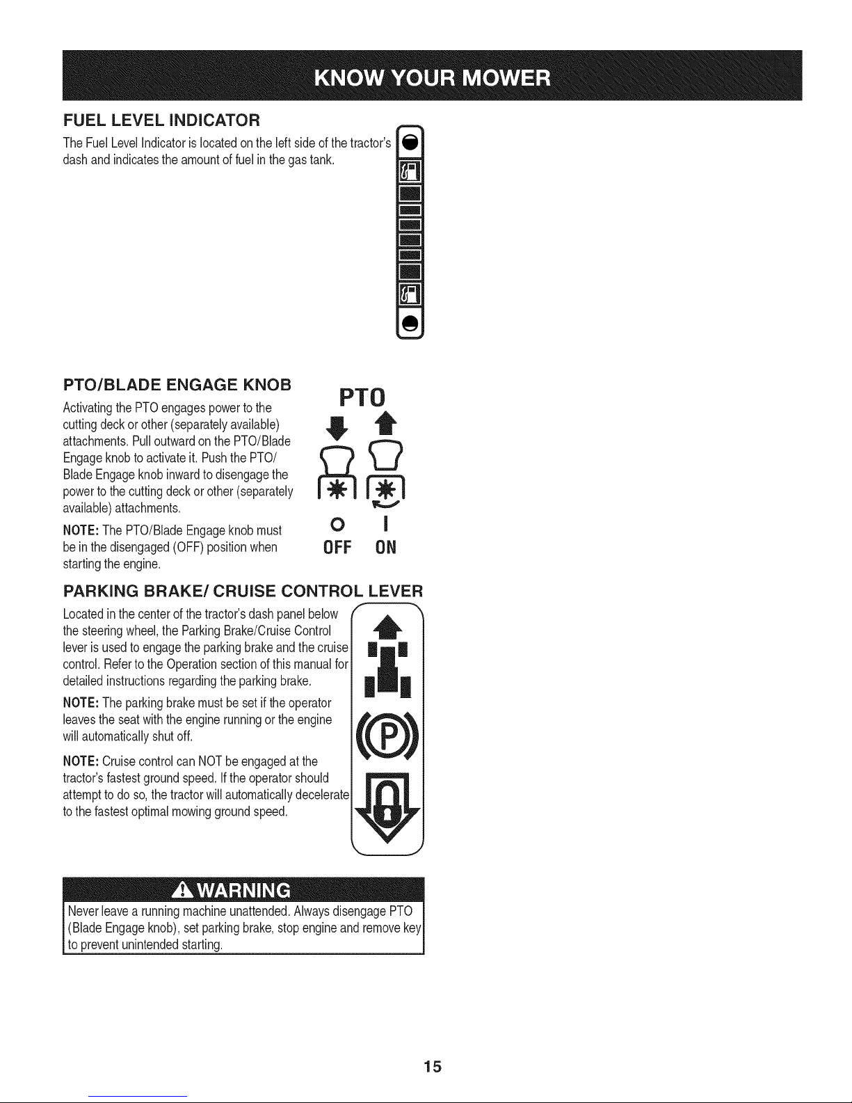
PTO/BLADE ENGAGE KNOB
Activatingthe PTOengagespowerto the
cuttingdeckor other(separatelyavailable)
attachments.Pulloutwardon thePTO/Blade
Engageknobto activateit. PushthePTO/
BladeEngageknobinwardto disengagethe
powertothecuttingdeckorother(separately
available)attachments.
NOTE:The PTO/BladeEngageknobmust
bein the disengaged(OFF)positionwhen
startingtheengine.
PTO
OFF 0N
PARKING BRAKE/CRUISE CONTROL LEVER
Locatedinthecenterofthe tractor'sdashpanelbelow
thesteeringwheel,the ParkingBrake/CruiseControl
leveris usedtoengagethe parkingbrakeandthe cruise
control.Refertothe Operationsectionof thismanualfor
detailedinstructionsregardingtheparkingbrake.
NOTE:The parkingbrakemustbe setiftheoperator
leavestheseatwiththeenginerunningorthe engine _,#_,
willautomaticallyshutoff.
,krPJ
NOTE:Cruisecontrolcan NOTbeengagedatthe
tractor'sfastestgroundspeed.If theoperatorshould
attempttodo so,thetractorwill automaticallydecelerate
tothe fastestoptimalmowinggroundspeed.
Neverleavea runningmachineunattended.AlwaysdisengagePTO
(BladeEngageknob),setparkingbrake,stopengineandremovekey
to preventunintendedstarting.
15
Page 16
SAFETY iNTERLOCK SWITCH ES
Thistractoris equippedwitha safetyinterlocksystemforthe protection
ofthe operator.Ifthe interlocksystemshouldevermalfunction,do not
operatethetractor.Contacta Searsorotherqualifiedservicedealer.
• The safetyinterlocksystempreventstheenginefromcrankingor
startingunlessthe parkingbrakeisengaged,andthe PTO(Blade
Engage)knobis in thedisengaged(OFF)position.
Theenginewill automaticallyshutoffif theoperatorleavesthe
seatbeforeengagingtheparkingbrake.
• TheelectricPTO(BladeEngage)clutchwillautomaticallyshut
off iftheoperatorleavesthetractor'sseatwiththe PTO(Blade
Engage)knobinthe engaged(ON) position,regardlessof
whetherthe parkingbrakeisengaged.
• Withthe ignitionkeyinthe NORMALMOWINGposition,the
electricPTO(BladeEngage)clutchwillautomaticallyshutoffif
thePTO(BladeEngage)knobismovedintotheengaged(ON)
positionwiththedrive pedalinpositionfor reversetravel.
Donotoperatethetractorifthe interlocksystemis malfunctioning.
Thissystemwasdesignedforyoursafetyandprotection.
StartingtheEngine
NOTE:Referto theAssembly& Set-Upsectionofthismanualfor
GasolineandOilfill-up instructions.
STOPPING THE ENGINE
Ifyoustrikeaforeignobject,stoptheengineanddisconnectthe
sparkplugwire(s).Thoroughlyinspectthemachineforanydamage.
Repairthedamagebeforerestartingandoperating.
1. Ifthebladesareengaged,placethe PTO/BladeEngageknobin
thedisengaged(OFF)position.
2. PlacethethrottlecontrolneartheSLOWposition.
3. Turnthe ignitionkeycounterclockwisetothe STOPposition.
4. Removethe keyfromthe ignitionswitchtopreventunintended
starting.
DRIVING THE TRACTOR
Avoidsuddenstarts,excessivespeedandsuddenstops.
1. Lightlypressthebrakepedalto releasetheparkingbrake.Move
thethrottleleverintotheFAST(rabbit)position.
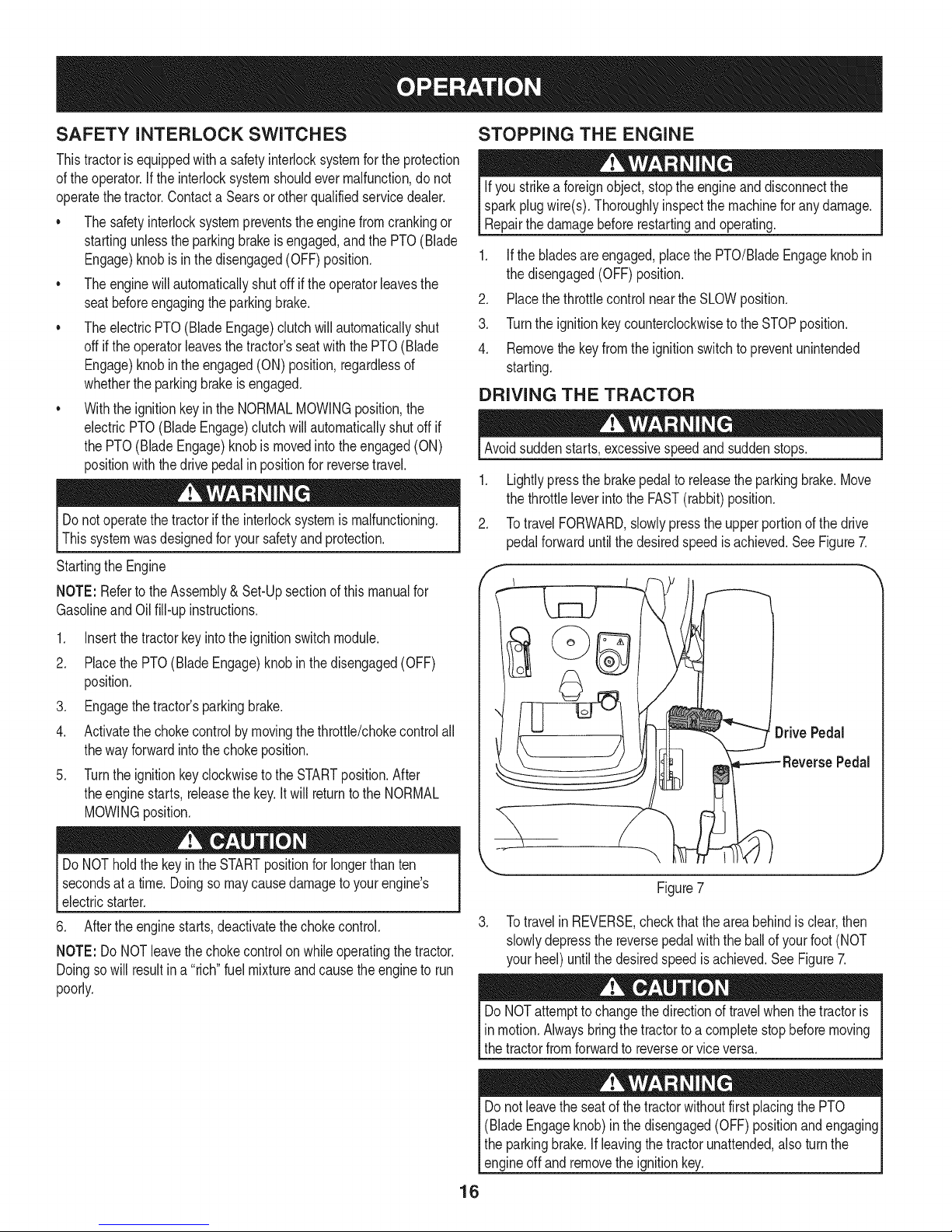
2. TotravelFORWARD,slowlypressthe upperportionofthe drive
pedalforwarduntilthe desiredspeedisachieved.SeeFigure7.
f
1. Insertthe tractorkeyintotheignitionswitchmodule.
2. Placethe PTO(BladeEngage)knobinthedisengaged(OFF)
position.
3. Engagethetractor'sparkingbrake.
4. Activatethechokecontrolby movingthethrottle/chokecontrolall
thewayforwardintothechokeposition.
5. TurntheignitionkeyclockwisetotheSTARTposition.After
theenginestarts,releasethekey.Itwill returntotheNORMAL
MOWINGposition.
DoNOTholdthekeyintheSTARTpositionforlongerthan ten
secondsata time.Doingso maycausedamagetoyourengine's
electricstarter.
6. Aftertheenginestarts,deactivatethechokecontrol.
NOTE:Do NOTleavethechokecontrolon whileoperatingthetractor.
Doingso willresultina "rich"fuelmixtureandcausetheengineto run
poorly.
/ O 'ti 0.,vow.o,
ReversePedal
J
Figure7
3. Totravelin REVERSE,checkthattheareabehindis clear,then
slowlydepressthe reversepedalwiththeballof yourfoot(NOT
yourheel)untilthe desiredspeedisachieved.SeeFigure7.
DoNOTattemptto changethedirectionoftravelwhenthetractoris
in motion.Alwaysbringthetractortoa completestopbeforemoving
thetractorfromforwardto reverseorviceversa.
Donot leavetheseatof thetractorwithoutfirstplacingthePTO
(BladeEngageknob)in thedisengaged(OFF)positionandengaging
theparkingbrake.Ifleavingthetractorunattended,alsoturn the
engineoff andremovetheignitionkey.
16
Page 17
REVERSE CAUTION MODE
TheREVERSECAUTIONMODEpositionof thekeyswitchmodule
allowsthetractorto beoperatedinreversewiththe blades(PTO)
engaged.
NOTE:Mowinginreverseisnotrecommended.
Useextremecautionwhileoperatingthetractorin theREVERSE
CAUTIONMODE.Alwayslookdownandbehindbeforeandwhile
backing.Donotoperatethetractorwhenchildrenorothersare
around.Stopthetractorimmediatelyif someoneentersthearea.
Touse theREVERSECAUTIONMODE:
NOTE:The operatorMUSTbe seatedinthe tractorseat.
1. Starttheengineaspreviouslyinstructedon thepreviouspage.
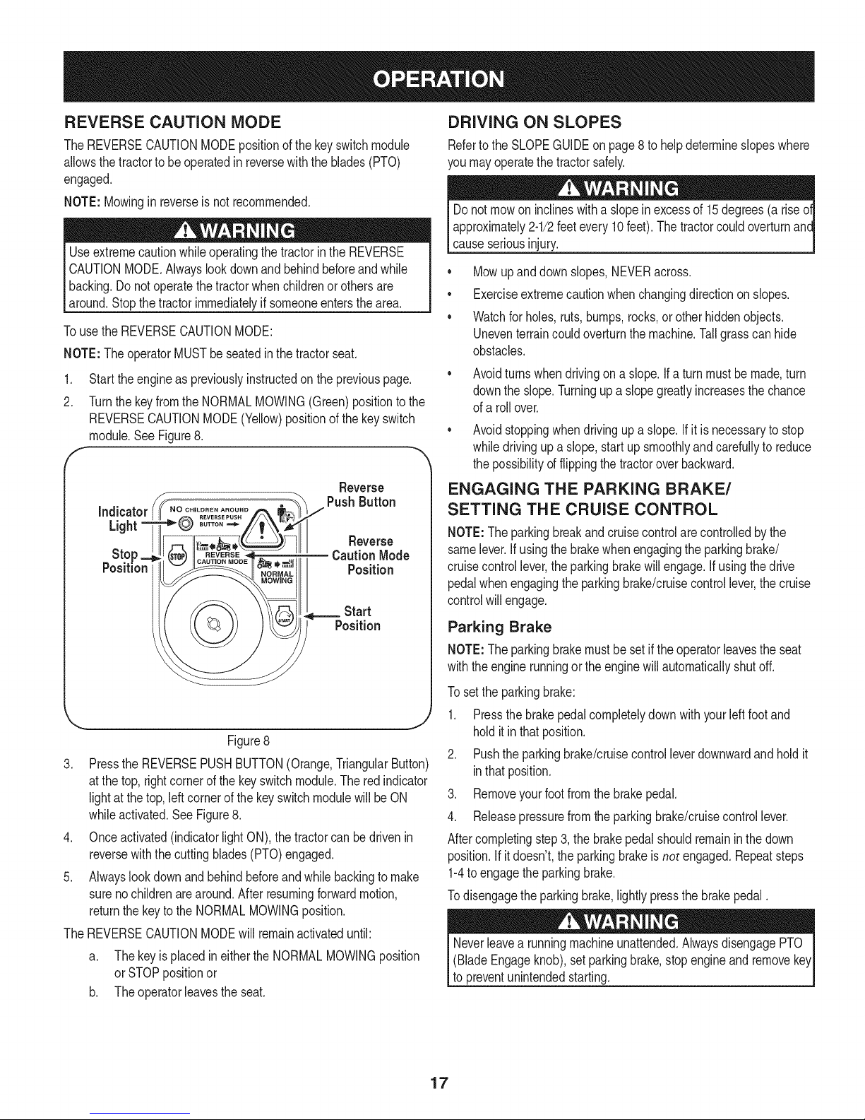
2. Turnthekeyfromthe NORMALMOWING(Green)positiontothe
REVERSECAUTIONMODE(Yellow)positionofthe keyswitch
module.SeeFigure8.
F "
Reverse
DRIVING ON SLOPES
Referto the SLOPEGUIDEon page8 to helpdetermineslopeswhere
youmayoperatethetractorsafely.
Donot mowon inclineswitha slopeinexcessof 15degrees(a rise
approximately2-1/2feetevery10feet).The tractorcouldoverturnanc
causeseriousinjury.
• Mowupanddownslopes,NEVERacross.
• Exerciseextremecautionwhenchangingdirectiononslopes.
• Watchforholes,ruts,bumps,rocks,or otherhiddenobjects.
Uneventerraincouldoverturnthe machine.Tallgrasscanhide
obstacles.
Avoidturnswhendrivingona slope.If a turnmustbe made,turn
downthe slope.Turningupa slopegreatlyincreasesthechance
ofa rollover.
Avoidstoppingwhendrivingupa slope.If itisnecessaryto stop
whiledrivingup a slope,startupsmoothlyandcarefullytoreduce
thepossibilityof flippingthetractoroverbackward.
ENGAGING THE PARKING BRAKE/
SETTING THE CRUISE CONTROL
NOTE:Theparkingbreakandcruisecontrolarecontrolledbythe
samelever.Ifusingthe brakewhenengagingtheparkingbrake/
cruisecontrollever,theparkingbrakewillengage.Ifusingthe drive
pedalwhenengagingtheparkingbrake/cruisecontrollever,thecruise
controlwillengage.
Figure8
3. PresstheREVERSEPUSHBUTTON(Orange,TriangularButton)
atthe top,rightcornerofthe keyswitchmodule.Theredindicator
lightat thetop,leftcornerofthekeyswitchmodulewillbeON
whileactivated.SeeFigure8.
4. Onceactivated(indicatorlightON),thetractorcan bedrivenin
reversewiththecuttingblades(PTO)engaged.
5. Alwayslookdownand behindbeforeandwhilebackingtomake
surenochildrenarearound.Afterresumingforwardmotion,
returnthe keytotheNORMALMOWINGposition.
TheREVERSECAUTIONMODEwill remainactivateduntil:
a. ThekeyisplacedineithertheNORMALMOWINGposition
orSTOPpositionor
b. Theoperatorieavestheseat.
Parking Brake
NOTE:Theparkingbrakemustbesetif theoperatorleavestheseat
withtheenginerunningor theenginewillautomaticallyshutoff.
Tosettheparkingbrake:
1. Pressthebrakepedalcompletelydownwith yourleftfootand
holditinthat position.
2. Pushtheparkingbrake/cruisecontrolleverdownwardandholdit
inthatposition.
3. Removeyourfootfromthe brakepedal.
4. Releasepressurefromtheparkingbrake/cruisecontrollever.
Aftercompletingstep3,the brakepedalshouldremaininthedown
position.Ifitdoesn't,theparkingbrakeisnot engaged.Repeatsteps
1-4toengagethe parkingbrake.
Todisengagetheparkingbrake,lightlypressthebrakepedal.
(BladeEngageknob),setparkingbrake,stopengineandremove
to preventunintendedstarting.
17
Page 18
CruiseControl
Neverengagethe cruisecontrolleverwhiletravelinginreverse.
Tosetthe cruisecontrol:
1. Slowlypressthedrivepedalwithyourrightfootuntilthedesired
speedis achieved.
2. Lightlypresstheparkingbrake/cruisecontrolleverdownwardand
holditin thatposition.
3. Removeyourfootfromthedrivepedal.
4. Releasepressurefromtheparkingbrake/cruisecontrollever.
Aftercompletingstep3, thedrivepedalshouldremaininthedown
positionandthetractorwillmaintainthe sameforwardspeed.If it
doesn't,thecruisecontrolis notengaged.Repeatsteps1-4toengage
thecruisecontrol.
Todisengagethe cruisecontrol,lightlypressthedrivepedalor the
brakepedal.
NOTE:Cruisecontrolcannotbesetatthetractor'sfastestground
speed.If theoperatorshouldattempttodo so,thetractorwillautomati-
callydeceleratetothefastestoptimalmowinggroundspeed.
Tochangethedirectionof travelfromforwardto reversewhencruise
controlisengaged,pressthebrakepedalto disengagethecruise
controlandbringthetractortoa completestop.Thenslowlypressthe
reversepedalwiththeballofyourfootto travelinreverse.
USING THE DECK LIFT LEVER
Toraisethecuttingdeck,movethedecklift leverto theleft,thenplace
itin thenotchbestsuitedforyourapplication.
OPERATING THE HEADLIGHTS
ThelampsareONwhenevertheignitionkeyisrotatedoutoftheSTOP
position.ThelampsturnOFFwhenthe ignitionkeyis movedto the
STOPposition.
ENGAGING THE PTO
Engagingthe PTOtransferspowertothecuttingdeckor other
(separatelyavailable)attachments.Toengagethe PTO:
1. MovethethrottlecontrollevertotheFAST(rabbit)position.
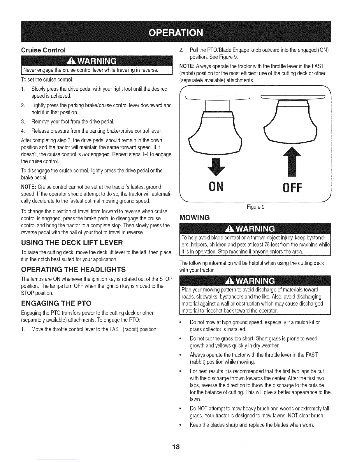
2. Pullthe PTO/BladeEngageknoboutwardinto theengaged(ON)
position.SeeFigure9.
NOTE:Alwaysoperatethetractorwiththethrottleleverin theFAST
(rabbit)positionfor themostefficientuseofthecuttingdeckor other
(separatelyavailable)attachments.
I _"
!I,
ON
Figure9
MOWING
Tohelpavoidbladecontactora thrownobjectinjury,keepbystand-
ers,helpers,childrenandpetsatleast75feetfromthemachinewhile
it isin operation.Stopmachineifanyoneentersthearea.
Thefollowinginformationwill behelpfulwhenusingthecuttingdeck
withyourtractor.
Planyourmowingpatternto avoiddischargeof materialstoward
roads,sidewalks,bystandersandthe like.Also,avoiddischarging
materialagainstawallorobstructionwhichmaycausedischarged
materialtoricochetbacktowardtheoperator.
• Donot mowat highgroundspeed,especiallyif a mulchkitor
grasscollectoris installed.
• Donot cutthe grasstooshort.Shortgrassis proneto weed
growthandyellowsquicklyindryweather.
• AlwaysoperatethetractorwiththethrottleleverintheFAST
(rabbit)positionwhilemowing.
• Forbestresultsit isrecommendedthatthefirst twolaps becut
withthedischargethrowntowardsthecenter.Afterthefirsttwo
laps, reversethedirectionto throwthedischargeto theoutside
forthe balanceofcutting.Thiswillgivea betterappearanceto the
lawn.
OFF
J
DoNOTattemptto mowheavybrushand weedsorextremelytall
grass.Yourtractorisdesignedtomowlawns,NOTclearbrush.
• Keepthebladessharpandreplacethebladeswhenworn.
18
Page 19
Beforeperforminganytypeofmaintenance/service,disengageall
controlsandstoptheengine.Waituntilallmovingpartshavecometo
acompletestop.Disconnectsparkplugwireandgrounditagainstthe
engineto preventunintendedstarting.Alwayswearsafetyglassesduring
operationorwhileperforminganyadjustmentsor repairs.
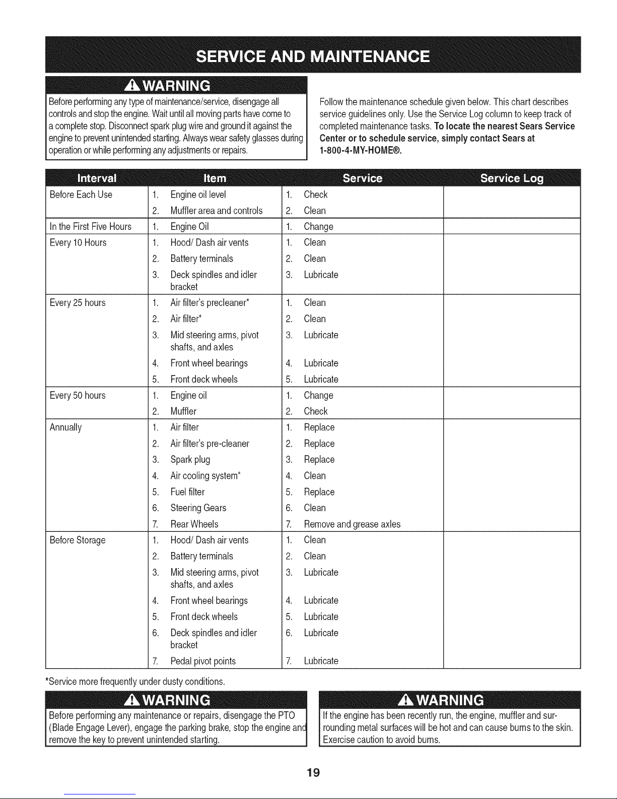
Followthe maintenanceschedulegivenbelow.Thischartdescribes
serviceguidelinesonly.Usethe ServiceLogcolumnto keeptrackof
completedmaintenancetasks.Tolocate the nearest SearsService
Centeror to scheduleservice,simplycontactSearsat
1-800-4-MY-HOME®.
BeforeEachUse
Inthe First FiveHours
Every10Hours
Every25 hours
Every50 hours
Annually
BeforeStorage
1. Engineoillevel
2. Mufflerareaandcontrols
1. EngineOil
1. Hood/Dashair vents
2. Batteryterminals
3. Deckspindlesandidler
bracket
1. Airfilter'sprecleaner*
2. Airfilter*
3. Midsteeringarms,pivot
shafts,andaxles
4. Frontwheelbearings
5. Frontdeckwheels
1. Engineoil
2. Muffler
1. Airfilter
2. Airfilter'spre-cleaner
3. Sparkplug
4. Aircoolingsystem*
5. Fuelfilter
6. SteeringGears
7. RearWheels
1. Hood/Dashair vents
2. Batteryterminals
3. Midsteeringarms,pivot
shafts,andaxles
4. Frontwheelbearings
5. Frontdeckwheels
6. Deckspindlesandidler
bracket
7. Pedalpivotpoints
1. Check
2. Clean
1. Change
1. Clean
2. Clean
3. Lubricate
1. Clean
2. Clean
3. Lubricate
4. Lubricate
5. Lubricate
1. Change
2. Check
1. Replace
2. Replace
3. Replace
4. Clean
5. Replace
6. Clean
7. Removeandgreaseaxles
1. Clean
2. Clean
3. Lubricate
4. Lubricate
5. Lubricate
6. Lubricate
7. Lubricate
*Servicemorefrequentlyunderdustyconditions.
(BladeEngageLever),engagethe parkingbrake,stoptheengine
removethe keyto preventunintendedstarting.
If theenginehasbeenrecentlyrun,theengine,mufflerandsur-
roundingmetalsurfaceswill behotandcancauseburnstothe skin.
Exercisecautiontoavoidburns.
19
Page 20
CUTTING DECK REMOVAL
Toremovethecuttingdeck, proceedasfollows:
1. Placethe PTO/BladeEngageknobinthedisengaged(OFF)
positionandengagetheparkingbrake.
2. Lowerthedeckby movingthedeck liftleverintothebottomnotch
ontherightfender.
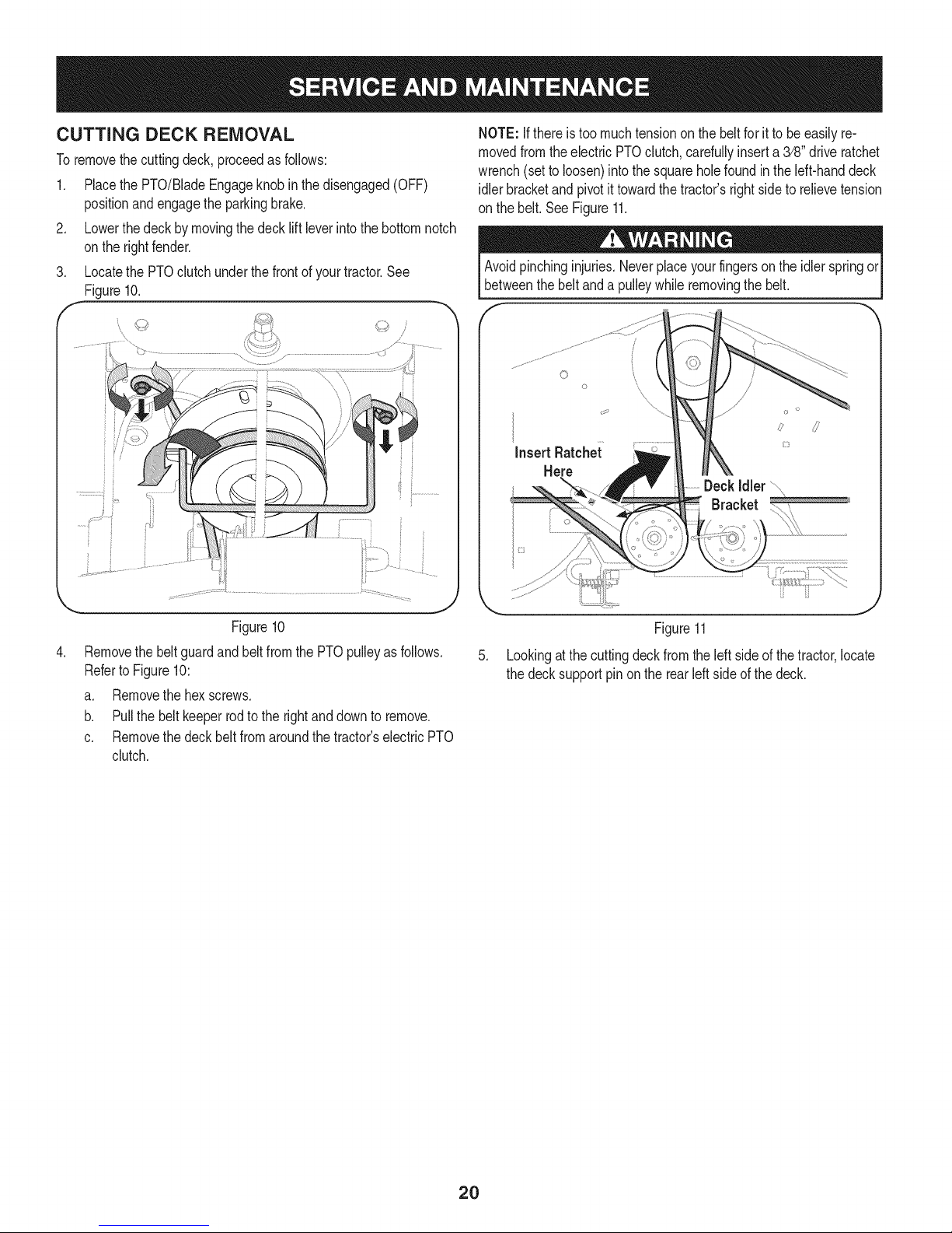
LocatethePTOclutchunderthefrontof yourtractor.See
Figure10.
NOTE:Ifthereis too muchtensionon thebeltforit to be easilyre-
movedfromtheelectric PTOclutch,cardully inserta 3/8"driveratchet
wrench(setto loosen)intothesquareholefoundin the left-handdeck
idlerbracketandpivotittowardthe tractor'srightsideto relievetension
on thebelt.SeeFigure11.
Avoidpinchinginjuries.Neverplaceyourfingersonthe idlerspringor
betweenthebeltanda pulleywhileremovingthe belt.
InsertRatche;c
Here
Figure10
.
Removethe beltguardand beltfromthePTOpulleyasfollows.
RefertoFigure10:
a. Removethehexscrews.
b. Pullthebeltkeeperrodtotherightanddownto remove.
c. Removethedeckbeltfromaroundthe tractor'selectricPTO
clutch.
J
_Y
Figure11
.
Lookingatthecuttingdeckfromthe leftsideof thetractor,locate
thedecksupportpinon therearleftsideof thedeck.
2O
Page 21
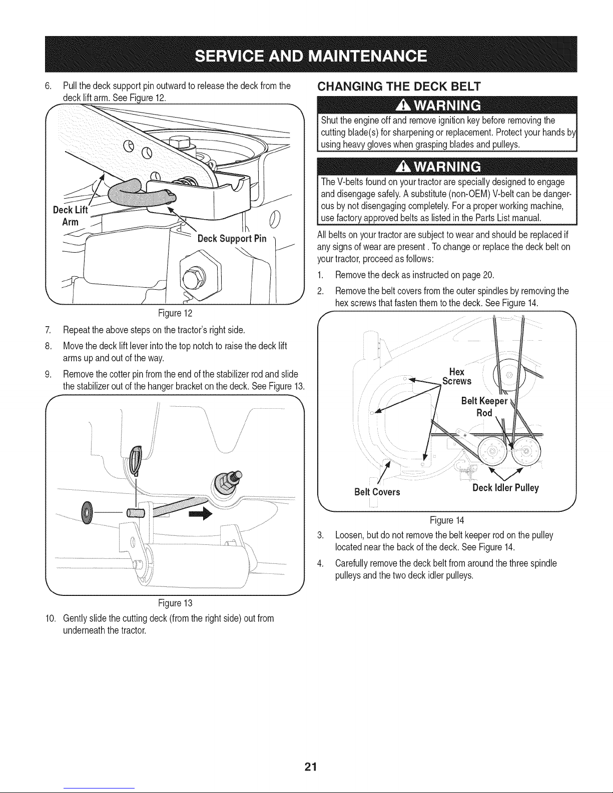
6. Pullthedeck supportpinoutwardtoreleasethedeckfromthe
deckliftarm.See Figure12.
0
DeckSupport Pin
Figure12
.
Repeattheabovestepsonthetractor'srightside.
8.
Movethedecklift leverintothetopnotchtoraisethedecklift
armsupandoutoftheway.
Removethecotterpinfromthe endof thestabilizerrodandslide
thestabilizeroutofthehangerbracketonthedeck.SeeFigure13.
/?
CHANGING THE DECK BELT
Shutthe engineoff andremoveignitionkeybeforeremovingthe
cuttingblade(s)forsharpeningor replacement.Protectyourhands
usingheavygloveswhengraspingbladesand pulleys.
TheV-beltsfoundon yourtractorarespeciallydesignedto engage
anddisengagesafely.A substitute(non-OEM)V-beltcan bedanger-
ousby notdisengagingcompletely.Foraproperworkingmachine,
usefactoryapprovedbeltsas listedin the PartsListmanual.
All beltsonyourtractoraresubjectto wearandshouldbereplacedif
anysignsof wear arepresent.Tochangeor replacethedeck belton
yourtractor,proceedasfollows:
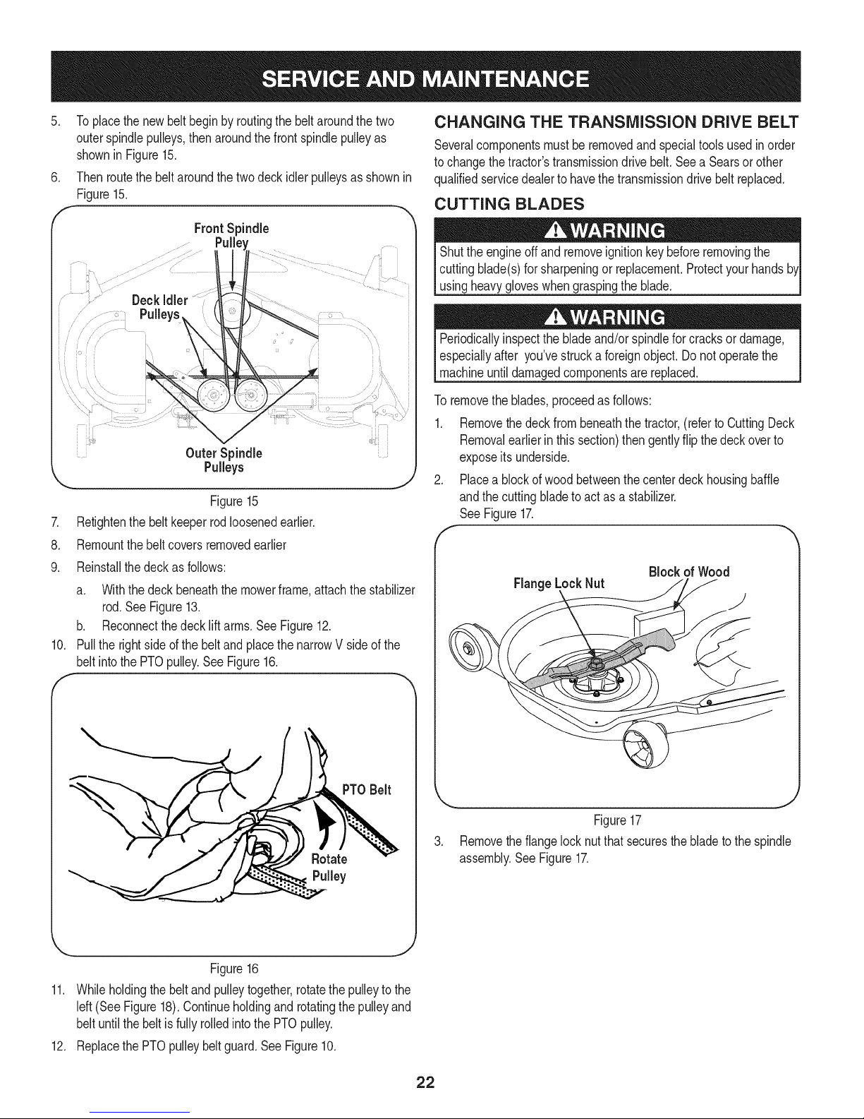
1. Removethedeckasinstructedon page20.
2. Removethe beltcoversfromtheouterspindlesby removingthe
hexscrewsthatfastenthemtothedeck.SeeFigure14.
Hex
Screws
Belt Keeper
Rod
/
___'
Figure13
10. Gentlyslidethe cuttingdeck(fromtherightside)outfrom
underneaththetractor.
Figure14
3. Loosen,butdonotremovethe belt keeperrodonthepulley
locatednearthebackof thedeck.SeeFigure14.
4. Carefullyremovethedeckbeltfromaroundthethreespindle
pulleysandthetwodeckidlerpulleys.
21
Page 22
.
Toplacethenewbelt beginby routingthebeltaroundthetwo
outerspindlepulleys,thenaroundthefront spindlepulleyas
shownin Figure15.
6. Thenroutethebeltaroundthe twodeckidlerpulleysasshownin
Figure15.
f
FrontSpindle
" Deck
Pulleys ....
Outer Spindle
Pulleys
Figure15
7. Retightenthebeltkeeperrodloosenedearlier.
8. Remountthebeltcoversremovedearlier
9. Reinstallthedeckasfollows:
a. Withthedeck beneaththemowerframe,attachthestabilizer
rod.SeeFigure13.
b. Reconnectthedeck liftarms.SeeFigure12.
10. Pulltherightside ofthe beltandplacethe narrowVsideofthe
beltintothePTOpulley.SeeFigure16.
CHANGING THE TRANSMISSION DRIVE BELT
Severalcomponentsmustbe removedand specialtoolsusedinorder
tochangethetractor'stransmissiondrivebelt.Seea Searsorother
qualifiedservicedealerto havethetransmissiondrivebeltreplaced.
CUTTING BLADES
Shutthe engineoff andremoveignitionkeybeforeremovingthe
cuttingblade(s)forsharpeningor replacement.Protectyourhands
usingheavygloveswhengraspingthe blade.
Periodicallyinspectthebladeand/orspindlefor cracksordamage,
especiallyafter you'vestrucka foreignobject.Donotoperatethe
machineuntildamagedcomponentsare replaced.
Toremovetheblades,proceedasfollows:
1. Removethedeckfrombeneaththetractor,(refertoCuttingDeck
Removalearlierinthissection)thengentlyflip thedeckoverto
exposeitsunderside.
2. Placea blockof woodbetweenthe centerdeckhousingbaffle
andthecuttingbladeto actas a stabilizer.
See Figure17.
f
Block of Wood
FlangeLockNut
)
Figure16
11. Whileholdingthe beltandpulleytogether,rotatethepulleytothe
left(See Figure18).Continueholdingandrotatingthepulleyand
beltuntilthebeltis fullyrolledintothePTOpulley.
12. Replacethe PTOpulleybeltguard.SeeFigure10.
PTO Belt
Figure17
3. Removethe flangelocknutthat securesthebladetothespindle
assembly.SeeFigure17.
J
22
Page 23

Toproperlysharpenthecuttingblades,removeequalamounts
4. Jump Starting
ofmetalfrombothendsofthebladesalongthecuttingedges,
paralleltothetrailingedge,ata 250.to300angle.Alwaysgrind
eachcuttingbladeedgeequallytomaintainproperbladebalance.
SeeFigure18.
Ifthecuttingedgeof thebladehaspreviouslybeensharpened,orif
anymetalseparationis present,replacethebladeswithnewones.
A poorlybalancedbladewillcauseexcessivevibration,maycause
damage to the tractor and/or result inpersonal injury.
\..\
.2
Neverjump starta damagedor frozenbattery.Becertainthevehicles
do nottouchandignitionsareoff.Donot allowcableclampstotouch.
1. Connectpositive(+)cabletopositive(+) postof yourtractor's
dischargedbattery.
2. Connectthe otherendofthecableto thepositive(+) postof the
jumperbattery.
3. Connectthe negative(-) cabletothe negative(-) postof the
jumperbattery.
4. Makethefinalconnectionon theengineblockof thetractor,away
fromthebattery.Attachtoan unpaintedparttoassurea good
connection.
Ifthejumperbatteryisinstalledona vehicle(i.e.car,truck),do NOT
startthe vehicle'senginewhenjumpstartingyourtractor.
5. Startthe tractor(asinstructedintheOperationsectionofthis
manual).
6. Setthetractor'sparkingbrakebeforeremovingthejumpercables.
Removecablesinreverseorderofconnection.
Charging
J
Figure18
5. Testtheblade'sbalanceusinga bladebalancer.Grindmetalfrom
theheavyside untilit balancesevenly.
NOTE:Whenreplacingtheblade,besureto installthe bladewiththe
sided theblademarked"Bottom"(orwitha partnumberstampedin
it)facingthe groundwhenthemowerisin theoperatingposition.
Useatorquewrenchtotightenthe bladespindlehexflangenutto
between70ft-lbsand90ft-lbs.
BATTERY
Batteryposts,terminals,andrelatedaccessoriescontainleadand
leadcompounds,chemicalsknowntotheStateofCaliforniato cause
cancerandreproductiveharm.Washhandsafterhandling.
If removingthe battery,disconnecttheNEGATIVE(Black)wire |
from itsterminalfirst,followedby thePOSITIVE(Red)wire.When
reinstallingthebattery,alwaysconnectthe POSITIVE(Red)wiretoit
terminalfirst,followedbythe NEGATIVE(Black)wire.
Batteriesgiveoff an explosivegas whilecharging.Chargethebattery[
in a wellventilatedareaandkeepawayfroman openflameorpilot [
lightas on a waterheater,spaceheater,furnace,clothesdryeror [
othergas appliances. J
Whenchargingyourtractor'sbattery,use onlyachargerdesignedfor
12Vlead-acidbatteries.Readyourbatterycharger'sOwner'sManual
priortochargingyourtractor'sbattery.Alwaysfollowitsinstructions
andheeditswarnings.
Ifyourtractorhasnotbeenputintouseforanextendedperiodoftime,
chargethe batteryasfollows:
1. Setyourbatterychargertodelivera maxof10amperes.
2. Ifyour batterychargeris automatic,chargethe batteryuntilthe
chargerindicatesthatchargingis complete.If thechargerisnot
automatic,chargefor nofewerthaneighthours.
TIRES
Neverexceedthe maximuminflationpressureshownonthesidewall
ofthe tire.
Referto thetiresidewallforexacttiremanufacturer'srecommendedor
maximumpsi.Donotoverinflate.
t
Uneventire pressurecouldcausethecuttingdecktomowunevenly.
23
Page 24
FUSE
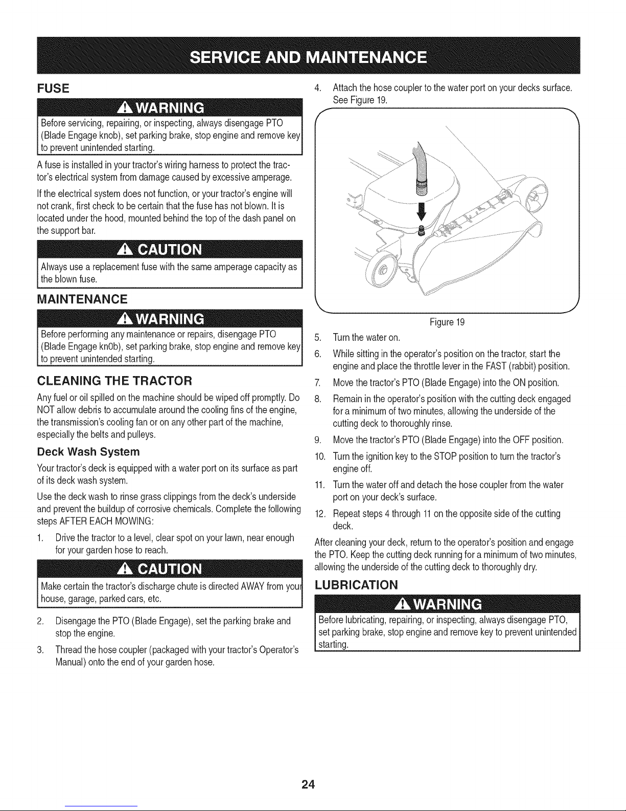
4. Attachthe hosecouplerto thewaterportonyourdeckssurface.
See Figure19.
Beforeservicing,repairing,or inspecting,alwaysdisengagePTO
(BladeEngageknob),setparkingbrake,stopengineandremove
topreventunintendedstarting.
Afuse isinstalledinyourtractor'swiringharnessto protectthetrac-
tor'selectricalsystemfromdamagecausedbyexcessiveamperage.
Iftheelectricalsystemdoesnot function,or yourtractor'senginewill
notcrank,firstcheckto becertainthatthe fusehasnotblown.It is
locatedunderthehood,mountedbehindthetop ofthedashpanelon
thesupportbar.
Alwaysusea replacementfusewiththe sameamperagecapacityas
theblownfuse.
MAINTENANCE
Beforeperforminganymaintenanceor repairs,disengagePTO
(BladeEngageknOb),setparkingbrake,stopengineand remove
topreventunintendedstarting.
CLEANING THE TRACTOR
Anyfuel oroil spilledonthemachineshouldbewipedoff promptly.Do
NOTallowdebristoaccumulatearoundthe coolingfinsofthe engine,
thetransmission'scoolingfanor onanyotherpartofthe machine,
especiallythebeltsandpulleys.
Deck Wash System
Yourtractor'sdeckisequippedwithawaterportonitssurfaceaspart
ofitsdeckwashsystem.
Usethedeckwashtorinsegrassclippingsfromthe deck'sunderside
andpreventthebuildupofcorrosivechemicals.Completethefollowing
stepsAFTEREACHMOWING:
1. Drivethetractorto a level,clearspotonyour lawn,nearenough
foryourgardenhoseto reach.
Makecertainthetractor'sdischargechuteisdirectedAWAYfromyoul
house,garage,parkedcars,etc.
\\
\\
Figure19
5. Turnthe wateron.
6. Whilesittingin the operator'spositionon the tractor,startthe
engineand placethethrottleleverintheFAST(rabbit)position.
7. Movethetractor'sPTO(BladeEngage)intothe ON position.
8. Remainintheoperator'spositionwiththecuttingdeckengaged
fora minimumoftwominutes,allowingthe undersideofthe
cuttingdeckto thoroughlyrinse.
9. Movethetractor'sPTO(BladeEngage)intothe OFFposition.
10. TurntheignitionkeytotheSTOPpositiontoturnthetractor's
engineoff.
11. Turnthewateroffanddetachthehosecouplerfromthewater
porton yourdeck'ssurface.
12. Repeatsteps4 through11ontheoppositesideofthe cutting
deck.
Aftercleaningyourdeck,returntotheoperator'spositionandengage
the PTO.Keepthecuttingdeck runningfora minimumof two minutes,
allowingtheundersideofthecuttingdecktothoroughlydry.
LUBRICATION
2. DisengagethePTO(BladeEngage),settheparkingbrakeand
stoptheengine.
3. Threadthehosecoupler(packagedwithyourtractor'sOperator's
Manual)ontotheendofyour gardenhose.
Beforelubricating,repairing,orinspecting,alwaysdisengagePTO,
setparkingbrake,stopengineandremovekeytopreventunintended
starting.
24
Page 25
Front Wheels
Eachof thefrontwheelaxlesandrimsisequippedwitha grease
fitting.SeeFigure20.Lubricatewitha No.2 multi-purposegrease
appliedwitha greasegunafterevery25 hoursoftractoroperation.
?
J_
\ \
Figure20
Pivot Points & Linkage
Lubricateall thepivotpointson thedrivesystem,parkingbrakeandlift
linkageat leastoncea seasonwithlightoil.
Deck Wheels
Eachof thetractordeck'sfrontgaugewheelsisequippedwitha
greasefitting.Lubricatewitha No.2 multi-purposegreaseappliedwith
a greasegunafterevery25 hoursoftractoroperation.
Deck Spindle
Greasefittingscanbe foundon eachdeckspindle.SeeFigure21.
Lubricatewith251HEPgreaseoran equivalentNo.2 multi-purpose
lithiumgrease.Usinga greasegun,applytwostrokes(minimum)or
sufficientgreasetothe spindleshaft.
f \J
ADJUSTMENTS
Shutthe engineoff,removethe ignitionkeyandengagetheparking
brakebeforemakingadjustments.Protectyourhandsbyusingheavy
gloveswhenhandlingthe blades.
NOTE:Checkthetractor'stirepressurebeforeperformingany deck
levelingadjustments.Referto Tireson page23 forinformationregard-
ingtirepressure.
Leveling the Deck (Front To Rear)
Thefrontofthecuttingdeckis supportedby a stabilizerbarthatcan
beadjustedto levelthedeckfromfrontto rear.Thefrontof thedeck
shouldbebetween1/4"and3/8"lowerthanthe rearofthedeck.Adjust
ifnecessaryasfollows:
1. Parkthetractorparkedonafirm, levelsurfaceandplacethedeck
liftleverinthemiddleposition.
2. Rotatethebladenearestthe dischargechutecoversothat itis
parallelwiththetractor.
3. Measurethedistancefromthe frontof thebladetiptothe ground
andthe rearofthebladetip tothe ground.Thefirst measurement
takenshouldbebetween1/4"and3/8"lessthanthesecond
measurement.
Determinethe approximatedistancenecessaryfor properadjustment
and proceed,ifnecessary.
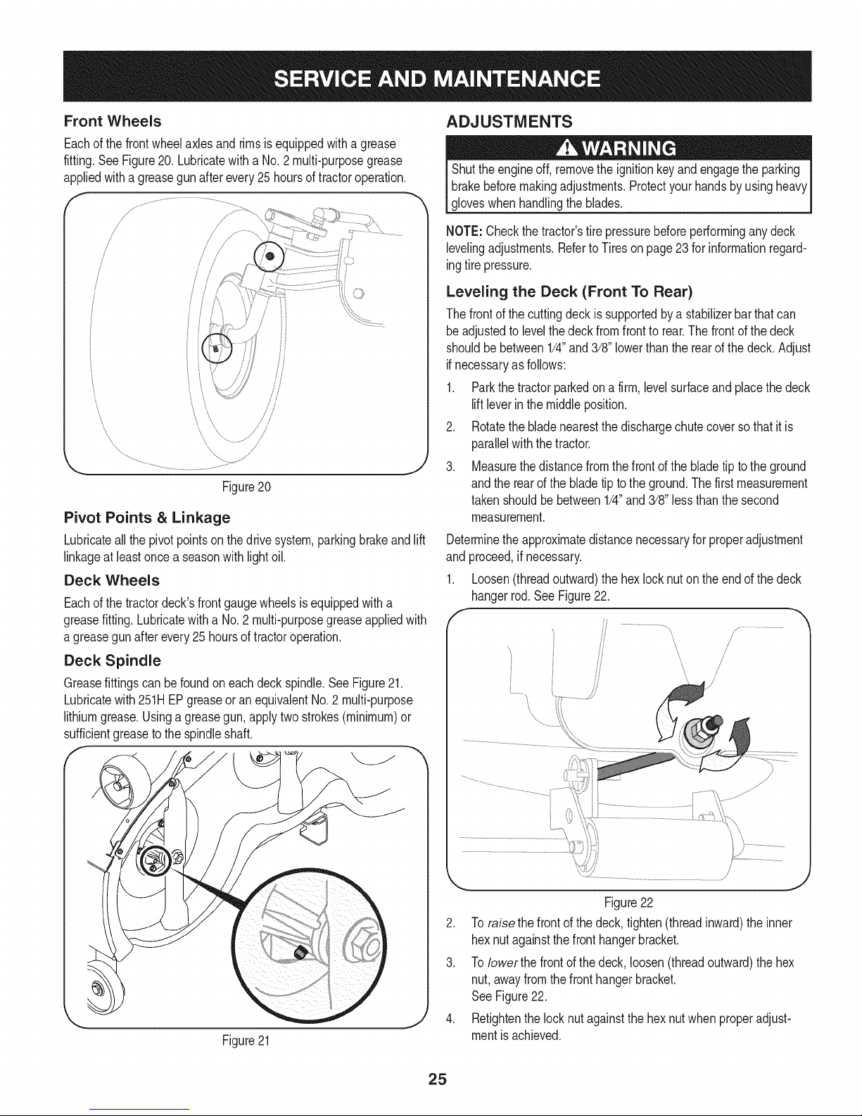
1. Loosen(threadoutward)thehexlocknutontheendofthedeck
hangerrod.SeeFigure22.
/
/
!
Figure21
Figure22
2. Toraisethe frontof the deck,tighten(threadinward)theinner
hexnutagainstthefronthangerbracket.
3. ToIowerthe frontofthedeck,loosen(threadoutward)thehex
nut,awayfromthefronthangerbracket.
SeeFigure22.
4. Retightenthe locknutagainstthehexnutwhenproperadjust-
mentisachieved.
25
Page 26
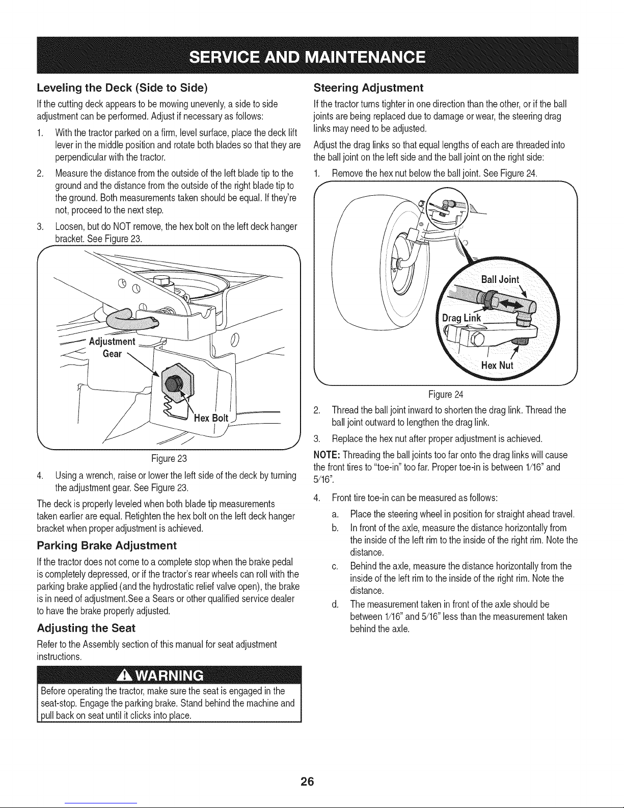
Leveling the Deck (Side to Side)
Ifthecuttingdeckappearsto bemowingunevenly,a sidetoside
adjustmentcanbe performed.Adjustif necessaryasfollows:
1. Withthetractorparkedon a firm,levelsurface,placethedecklift
leverinthe middlepositionandrotatebothbladessothattheyare
perpendicularwiththetractor.
2. Measurethedistancefromtheoutsideofthe leftbladetip to the
groundandthedistancefromtheoutsideof therightbladetip to
theground.Bothmeasurementstakenshouldbeequal.Ifthey're
not,proceedtothenextstep.
3. Loosen,butdo NOTremove,thehexboltonthe left deckhanger
bracket.See Figure23.
Adjustment
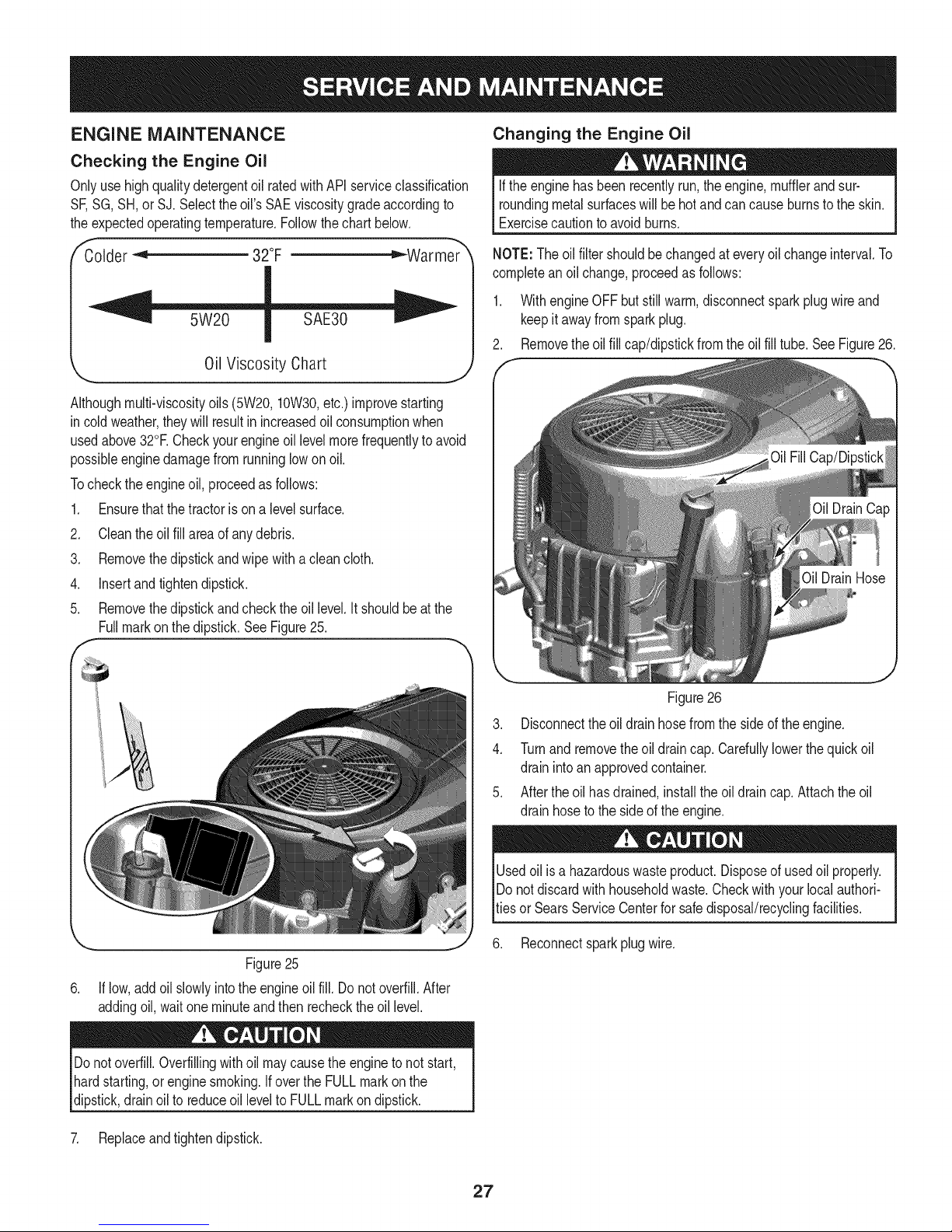
Steering Adjustment
Ifthetractorturnstighterinonedirectionthantheother,or iftheball
jointsarebeingreplacedduetodamageorwear,the steeringdrag
linksmayneedto beadjusted.
Adjustthedraglinkssothatequallengthsofeach arethreadedinto
theballjointonthe left sideandtheballjointonthe rightside:
1. Removethehexnut belowtheballjoint.SeeFigure24.
Figure23
4. Usinga wrench,raiseorlowerthe leftsideof thedeck byturning
theadjustmentgear.SeeFigure23.
Thedeckis properlyleveledwhenbothbladetip measurements
takenearlierareequal.Retightenthehexboltontheleftdeckhanger
bracketwhenproperadjustmentis achieved.
Parking Brake Adjustment
Ifthetractordoesnotcometo a completestopwhenthebrakepedal
iscompletelydepressed,or ifthetractor'srearwheelscanrollwiththe
parkingbrakeapplied(andthehydrostaticreliefvalveopen),thebrake
isin needof adjustment.Seea Searsorotherqualifiedservicedealer
tohavethebrakeproperlyadjusted.
Adjusting the Seat
Refertothe Assemblysectionofthismanualforseatadjustment
instructions.
Figure24
2. Threadthe balljoint inwardto shortenthedraglink.Threadthe
balljointoutwardtolengthenthedraglink.
3. Replacethehexnut afterproperadjustmentisachieved.
NOTE:Threadingtheballjointstoofarontothedraglinkswillcause
thefronttiresto"toe-in"toofar. Propertoe-in is between1/16"and
5/16".
4. Fronttiretoe-incan be measuredasfollows:
a. Placethesteeringwheelinpositionforstraightaheadtravel.
b. Infrontoftheaxle,measurethe distancehorizontallyfrom
theinsideoftheleft rimtothe insideof the rightrim.Notethe
distance.
c. Behindthe axle,measurethedistancehorizontallyfromthe
insideoftheleft rimtothe insideofthe rightrim.Notethe
distance.
d. Themeasurementtakeninfrontoftheaxleshouldbe
between1/16"and5/16"lessthanthe measurementtaken
behindtheaxle.
Beforeoperatingthe tractor,makesuretheseatis engagedin the
seat-stop.Engagethe parkingbrake.Standbehindthe machineand
pullbackon seatuntilitclicksintoplace.
26
Page 27
ENGINE MAINTENANCE
Checking the Engine Oil
Onlyuse highqualitydetergentoilratedwithAPIserviceclassification
SF,SG,SH,or SJ.Selecttheoil's SAEviscositygradeaccordingto
theexpectedoperatingtemperature.Followthe chartbelow.
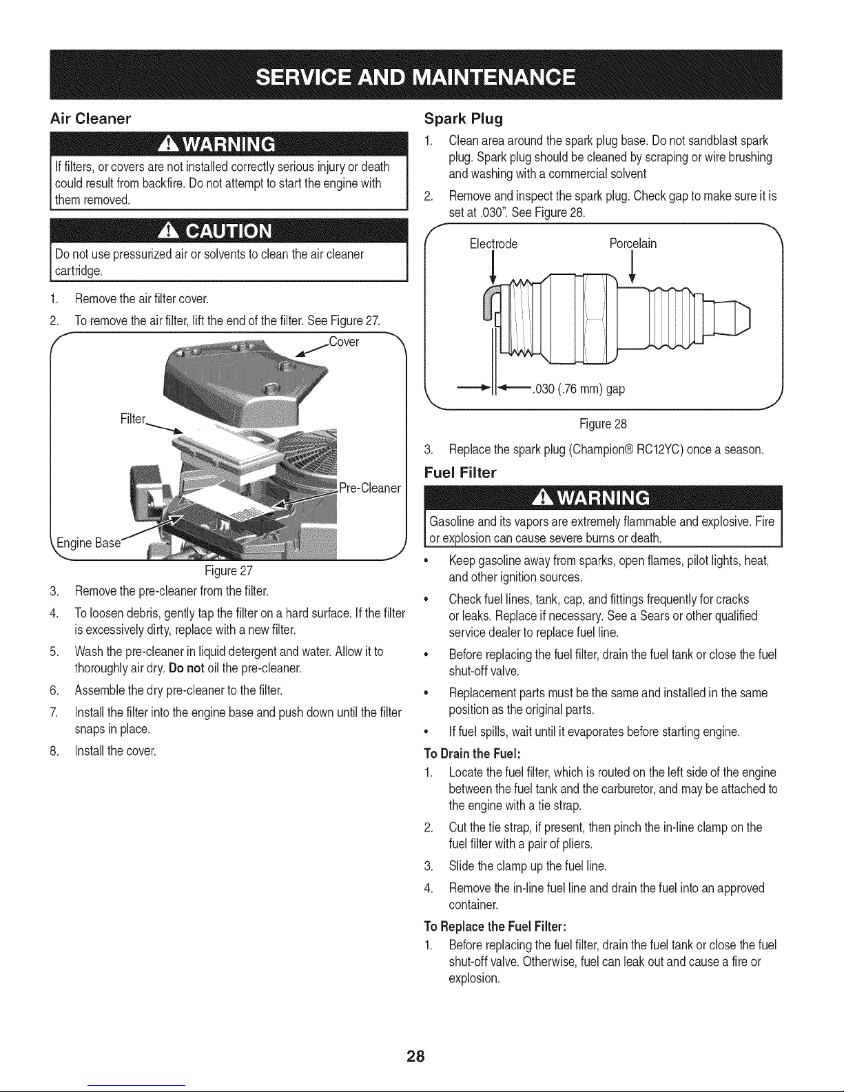
Changing the Engine Oil
Iftheenginehasbeenrecentlyrun,theengine,mufflerandsur-
roundingmetalsurfaceswill behot andcancauseburnsto the skin.
Exercisecautiontoavoidburns.
Colder"_ 32°F _Warmer
Oil Viscosity Chart
Althoughmulti-viscosityoils (5W20,10W30,etc.)improvestarting
in coldweather,theywillresultinincreasedoilconsumptionwhen
usedabove32°RCheckyourengineoillevelmorefrequentlytoavoid
possibleenginedamagefromrunninglowonoil.
Tochecktheengineoil,proceedasfollows:
.
Ensurethatthe tractorisonalevelsurface.
2.
Cleantheoil fill areaof anydebris.
3.
Removethedipstickandwipewithacleancloth.
4.
Insertandtightendipstick.
5.
Removethedipstickandcheckthe oil level.It shouldbeatthe
Fullmarkonthedipstick.SeeFigure25.
f
J
NOTE:Theoil filtershouldbe changedateveryoil changeinterval.To
completeanoilchange,proceedasfollows:
1. WithengineOFFbutstillwarm,disconnectsparkplugwireand
keepit awayfromsparkplug.
2. Removethe oilfill cap/dipstickfromtheoil fill tube.SeeFigure26.
Figure26
3. Disconnecttheoil drainhosefromthesideofthe engine.
4. Turnandremovethe oil draincap. Cardullylowerthequickoil
drainintoan approvedcontainer.
5. Aftertheoilhasdrained,installtheoil draincap.Attachtheoil
drainhoseto the sideof theengine.
,,. j
Figure25
6. If low,addoil slowlyintotheengineoilfill. Do notoverfill.After
addingoil,waitoneminuteand thenrechecktheoil level.
Donotoverfill.Overfillingwithoil maycausetheenginetonotstart,
hardstarting,orenginesmoking.IfovertheFULLmarkonthe
dipstick,drainoil toreduceoilleveltoFULLmarkondipstick.
7. Replaceandtightendipstick.
Usedoil isa hazardouswasteproduct.Disposeof usedoil properly.
IDo notdiscardwithhouseholdwaste.Checkwithyourlocalauthori-
_tiesorSearsServiceCenterforsafedisposal/recyclingfacilities.
6. Reconnectsparkplugwire.
27
Page 28
Air Cleaner
Iffilters,orcoversarenotinstalledcorrectlyseriousinjuryor death
couldresultfrombackfire.Do notattempttostarttheenginewith
themremoved.
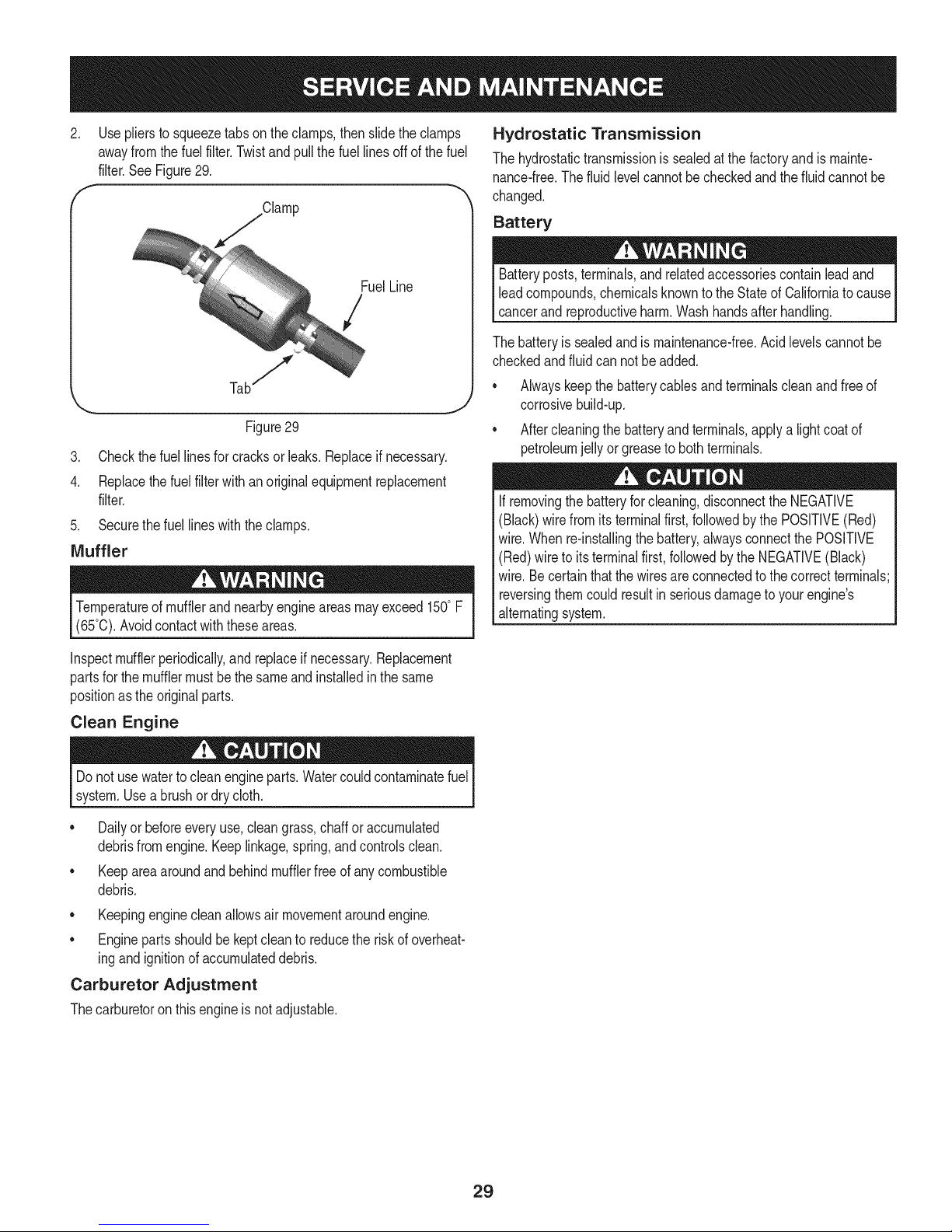
Spark Plug
1. Cleanareaaroundthesparkplugbase.Donotsandblastspark
plug.Sparkplugshouldbecleanedby scrapingor wirebrushing
andwashingwitha commercialsolvent
2. Removeandinspectthesparkplug.Checkgapto makesureitis
setat .030".SeeFigure28.
Donotusepressurizedair or solventstocleantheaircleaner
cartridge.
1. Removetheair filtercover.
2. Toremove the air filter,liftthe end of the filter.See Figure27.
E
/Cover
--ngine
Figure27
3. Removethe pre-cleanerfromthefilter.
4. Toloosendebris,gentlytapthefilterona hardsurface.Ifthefilter
isexcessivelydirty,replacewitha newfilter.
5. Washthepre-cleanerin liquiddetergentandwater.Allowit to
thoroughlyairdry.Donot oil thepre-cleaner.
6. Assemblethedrypre-cleanertothefilter.
7. Installthefilterinto theenginebaseandpushdownuntilthefilter
snapsin place.
8. Installthecover.
Electrode Porcelain
!
_ _-'-.030 (.76 ram) gap
Figure28
3. Replacethesparkplug(Champion®RC12YC)onceaseason.
Fuel Filter
Gasolineandits vaporsareextremelyflammableandexplosive.Fire
or explosioncancausesevereburnsordeath.
• Keepgasolineawayfromsparks,openflames,pilot lights,heat,
andotherignitionsources.
• Checkfuellines,tank,cap,andfittingsfrequentlyforcracks
or leaks.Replaceif necessary.Seea Searsorotherqualified
servicedealerto replacefuelline.
• Beforereplacingthe fuelfilter,drainthe fueltankor closethe fuel
shut-offvalve.
• Replacementpartsmustbethesameandinstalledinthesame
positionasthe originalparts.
• Iffuelspills,waituntilitevaporatesbeforestartingengine.
ToDrainthe Fuel:
1. Locatethefuel filter,whichisroutedontheleft sideoftheengine
betweenthefuel tankandthe carburetor,andmaybe attachedto
theenginewitha tiestrap.
2. Cutthetiestrap,if present,then pinchthein-lineclamponthe
fuelfilterwitha pairof pliers.
3. Slidetheclampup thefuelline.
4. Removethe in-linefuellineanddrainthefuelintoanapproved
container.
ToReplacethe Fuel Filter:
1. Beforereplacingthefuelfilter,drainthe fueltankor closethefuel
shut-offvalve.Otherwise,fuelcanleakoutandcausea fire or
explosion.
28
Page 29
2. Useplierstosqueezetabson theclamps,then slidetheclamps
awayfromthefuel filter.Twistand pullthefuellinesoff of the fuel
filter.SeeFigure29.
f Clamp
Hydrostatic Transmission
Thehydrostatictransmissionis sealedatthefactoryandis mainte-
nance-free.The fluid levelcannotbecheckedandthe fluidcannotbe
changed.
Battery
FuelLine
/
Figure29
3. Checkthefuellinesfor cracksor leaks.Replaceif necessary.
4. Replacethefuel filterwithanoriginalequipmentreplacement
filter.
5. Securethefuellineswiththeclamps.
Muffler
Temperatureof mufflerandnearbyengineareasmayexceed150°F
(65°0).Avoidcontactwiththeseareas.
Inspectmufflerperiodically,and replaceifnecessary.Replacement
partsforthemufflermustbethesameandinstalledinthesame
positionasthe originalparts.
Clean Engine
Batteryposts,terminals,and relatedaccessoriescontainleadand
leadcompounds,chemicalsknownto theStateofCaliforniato cause
cancerand reproductiveharm.Washhandsafterhandling.
Thebatteryissealedandismaintenance-free.Acidlevelscannotbe
checkedandfluid cannotbe added.
• Alwayskeepthebatterycablesandterminalscleanandfreeof
corrosivebuild-up.
Aftercleaningthebatteryandterminals,applya lightcoatof
petroleumjellyorgreasetobothterminals.
Ifremovingthebatteryforcleaning,disconnecttheNEGATIVE
(Black)wirefromitsterminalfirst,followedbythe POSITIVE(Red)
wire.Whenre-installingthebattery,alwaysconnectthe POSITIVE
(Red)wire toitsterminalfirst,followedbytheNEGATIVE(Black)
wire.Becertainthatthewiresareconnectedto thecorrectterminals;
reversingthemcouldresultinseriousdamagetoyourengine's
alternatingsystem.
Donotusewatertocleanengineparts.Watercouldcontaminatefuel
system.Useabrushordrycloth.
Dailyor beforeeveryuse,cleangrass,chafforaccumulated
debrisfromengine.Keeplinkage,spring,andcontrolsclean.
• Keepareaaroundandbehindmufflerfreeofanycombustible
debris.
• Keepingenginecleanallowsair movementaroundengine.
• Enginepartsshouldbekeptcleanto reducetheriskofoverheat-
ingandignitionofaccumulateddebris.
Carburetor Adjustment
Thecarburetoronthisengineisnot adjustable.
29
Page 30

Neverstorelawntractorwithfuelintankindoorsorin poorly
ventilatedareaswherefuelfumesmayreachanopenflame,spark,
or pilotlightasona furnace,waterheater,clothesdryer,or gas
appliance,
PREPARING THE ENGINE
IMPORTANT:Fuelleftinthefueltankduringwarmweatherdeterio-
ratesandwillcauseseriousstartingproblems.
Topreventgumdepositsfromforminginsidetheengine'scarburetor
andcausingpossiblemalfunctionoftheengine,thefuelsystemmust
beeithercompletelyemptied,or thegasolinemustbetreatedwitha
stabilizerto preventdeterioration.
If usingafuelstabilizer:
a. Readthe productmanufacturer'sinstructionsand recom-
mendations.
b. Addtoclean,freshgasolinethecorrectamountofstabilizer
forthecapacityofthefuelsystem.
c. Fillthefueltankwithtreatedfueland runtheenginefor2-3
minutestogetstabilizedfuelintothecarburetor.
If emptyingthefuelsystem:
a. Donotdrainfuel whentheengineishot.Allowtheengine
adequatetimetocool. Drainfuelintoan approvedcontainer
outdoors,awayfromopenflame.
b. Drainanylargevolumeof fuelfromthetankbydisconnect-
ingthefuellinefromthein-linefuelfilterneartheengine.
SeeToDraintheFuelonpage28.
PREPARING THE LAWN TRACTOR
• Cleanandlubricatetractorthoroughlyasdescribedin the
lubricationinstructions.
• Do notusea pressurewasherorgardenhosetocleanyour
unit.
• Storemowerina dry,cleanarea.Donotstorenextto
corrosivematerials,suchasfertilizer.
Gasolineisextremelyflammableandcanbeexplosiveundercertain
conditions.Draingasolinebeforestoringtheequipmentforextended
periods.Drainfuelonlyintoan approvedcontaineroutdoors,away
fromanopenflame.Allowengineto cool.Extinguishcigarettes,
cigars,pipes,andother sourcesofignitionpriortodrainingfuel.
Storegasolinein anapprovedcontainerin safelocation.
c. Reconnectthe fuellineand runtheengineuntilit startsto
falter,thenusethe choketo keeptheenginerunninguntilall
fuelin thecarburetorhasbeenexhausted.
d. Disconnectthefuellineanddrainanyremaininggasoline
fromthesystem.
Gasolineisa toxicsubstance.Disposeof gasolineproperly.Contact
yourlocal authoritiesforapproveddisposalmethods.
Removethesparkplugandpourone(1)ounceofengineoilthrough
thesparkplugholeintothe cylinder.Cranktheengineseveraltimesto
distributetheoil. Replacethe sparkplug.
30
Page 31

Beforeperforminganytypeof maintenance/service,disengageall
controlsandstoptheengine.Waituntilallmovingpartshavecometo
a completestop.Disconnectsparkplugwireandgroundit againstthe
engineto preventunintendedstarting.Alwayswearsafetyglassesduring
operationorwhileperforminganyadjustmentsorrepairs.
Thissectionaddressesminorserviceissues.Tolocate the nearestSearsService Centeror to scheduleservice,simplycontactSears
at 1-800-4-MY-HOME®.
Enginefailstostart
1. PTO/BladeEngageknobengaged.
2. Parkingbrakenotengaged.
3. Sparkplugwire disconnected.
4. Throttle/Chokecontrollevernotincorrect
1. Placeknobindisengaged(OFF)position.
2. Engageparkingbrake.
3. Connectwiretosparkplug.
4. PlaceThrottle/ChokelevertoFASTposition.
startingposition.
5. Fueltankempty,or stalefuel.
6. BIockedfuelline.
5. Filltankwithclean,fresh(lessthan30daysold)gas.
6. Replacefuelline.Seea Searsorotherqualified
servicedealer.Replacefuel filter.SeetheService
andMaintenancesection.
Enginerunserratically
7. Faultysparkplug.
8. Engineflooded.
1. Tractorrunningwith Chokeactivated.
7. Clean,adjustgapor replaceplug.
8. CrankenginewiththrottleinFASTposition.
1. MovetheThrottle/Chokecontrolleveroutofthe
chokeposition.
2. Sparkplugwiresloose.
3. Blockedfuellineor stalefuel.
2. Connectandtightensparkplugwires.
3. Replacefuelline.Seea Searsorotherqualified
servicedealer.Filltankwithclean,freshgasoline
andreplacefuelfilter.SeetheServiceand Mainte-
nancesection.
4. Ventingascap plugged.
5. Waterordirtin fuelsystem.
4. Clearventor replacecapifdamaged.
5. Drainfueltank.Refillwithclean,freshgasoline.See
theServiceand Maintenancesection.
6. Dirtyaircleaner.
.
Replaceair cleanerpaperelementorcleanfoam
precleaner.
Engineoverheats 1. Engineoillevellow 1.
2. Airflowrestricted 2.
Fillenginewith properamountandtype ofoil.
Cleangrassclippingsanddebrisfromaroundthe
engine'scoolingfinsandblowerhousing.
Enginehesitatesat high RPMs 1. Sparkpluggapsettooclose 1. Remove
Engineidlespoorly 1. Fouledsparkplug 1. Replace
2. Dirtyaircleaner 2. Replace
sparkplugandadjustgap.
sparkplugandadjustgap.
air cleanerelementand/orcleanpre-
cleaner.
Excessivevibration 1. Cuttingbladeslooseor unbalanced 1. Tightenbladeandspindle.Balanceblade.
2. Damaged,dull,orbentcuttingblade 2. Replaceblade.
31
Page 32

Mowerwill notmulchgrass
Unevencut
NEED MORE HELP?
Yotf_l.findthe answerandmoreon.ma_agemyheme,o{om- [o_h'ee!
oFindthisanda[[yourotherproductmanualson[ine.
o Get answers from our team of home experts.
oGeta persona[]zed ma]ntenance plan for your home.
oF]nd ]nformat]on and too[s to he[p w]th home projects.
maHage home
1. Enginespeedtoolow.
2. Wetgrass.
3. Excessivelyhighgrass.
4. Dullblade.
1. Decknotleveledproperly.
2. Dullblade.
3. Uneventirepressure.
1. PlaceThrottle/Chokecontrolin FAST(rabbit)
position.
2. Donotmulchwhengrassiswet.
3. Mowonceata highcuttingheight,thenmowagain
atdesiredheightor makea narrowercuttingswath.
4. Sharpenorreplaceblade.
1. Performside-to-sidedeckadjustment.
2. Sharpenorreplaceblade.
3. Checktirepressureinallfour tires.
b_o_tght to yo_ by Sears
_!i_iJii!ii@i!iii!iii!iii!iii!iii!iii!iii!iii!iii!iii!iii!iii!iii!iii!iii!iii!iii!iii!iii!iii!iii!iii!iii!iii!iii!iii!iii!iii!iii!iii!iii!iii!iii!iii!iii!iii!iii!iii!iii!iii!iii!iii!iii!iii!iii!iii!iii!iii!iii!iii!iii!iii!iii!iii!iii!iii!iii!iii!iii!iii!iii!iii!iii!iii!iii!iii!iii!iii!iii!iii!iii!iii!iii!iii!iii!iii!iii!iii!iii!iii!iii!iii!iii!iii!iii!iii!iii!iii!iii!iii!iii!iii!iii!iii!iii!iii!iii!iii!iii!iii!iii!iii!iii!iii!iii!iii!iii!iii!iii!iii!iii!iii!iii!iii!iii!iii!iii!iii!iii!iii!iii!iii!iii!iii!iii!iii!iii!iii!iii!iii!iii!iii!iii!iii!iii!iii!iii!iii!iii!iii!iii!iii@
32
Page 33

Congratulationson makingasmartpurchase.YournewCraftsman@
productisdesignedandmanufacturedfor yearsofdependableopera-
tion.Butlikeall products,it mayrequirerepairfromtimetotime.That's
whenhavinga RepairProtectionAgreementcansaveyoumoneyand
aggravation.
Here'swhattheRepairProtectionAgreement*includes:
* Expert service byour 10,000professionalrepairspecialists
o Unlimitedserviceand no chargefor partsand laboron all
coveredrepairs
o Product replacementupto $1500if yourcoveredproductcan't be
fixed
• Discountof 10%from regularpriceofserviceandrelatedinstalled
partsnotcoveredby theagreement;also,10%off regularpriceof
preventivemaintenancecheck
• Fast help byphone- wecall itRapidResolution- phonesupport
froma Searsrepresentative.Thinkof usas a "talkingowner's
manual."
Onceyoupurchasethe Agreement,a simplephonecallisall thatit
takesfor youto scheduleservice.Youcan callanytimedayor night,or
schedulea serviceappointmentonline.
TheRepairProtectionAgreementisa risk-freepurchase.Ifyoucancel
forany reasonduringtheproductwarrantyperiod,wewillprovideafull
refund.Or,a proratedrefundanytimeaftertheproductwarrantyperiod
expires.PurchaseyourRepairProtectionAgreementtoday!
Somelimitationsandexclusionsapply. Forpricesand additional
informationin the U.S.A.call 1-800-827-6655.
*CoverageinCanadavaries on some items.Forfull details call
SearsCanadaat 1-800-361-6665.
SearsInstallation Service
ForSearsprofessionalinstallationofhomeappliances,garagedoor
openers,waterheaters,andothermajorhomeitems,in the U.S.A.or
Canadacall1-800-4-MY-HOME®.
33
Page 34

Steering and Axle B Model No. 247.28981
2
7
19
17
6
12
9
23
34
Page 35

Steering and Axle B IViodel No. 247.28981
710-04095 HexHeadScrew,3/8-16:1.00 638-04028-0637 LHAxleAssembly
2 710-0514 HexHeadScrew,3/8-16:1.00 22 710-0395 HexHeadScrew,5/16-18:2.25
3 710-0643 HexHeadScrew,5/16-18:1.00 23 710-0859 HexHeadScrew,3/8-16:2.50
4 711-04998 LHDragLink 24 710-3180 HexHeadScrew,5/16-18:1.75
5 711-04999 RHDragLink 25 912-0214 HexlockNut,3/8-24
6 912-0240 JamNut,7/16-20 26 712-04063 FlangelockNut,5/16-18
7 712-04065 FlangelockNut,3/8-16 27 714-0162 CotterPin,5/32:1.25
8 712-0459 FlangelockNut,7/16-20 28 719-04413A PivotBarAxle
9 712-3004A FlangelockNut,5/16-18 29 748-04065-0637 SteeringBlock
10 717-1550F SteeringGear 30 748-04068 Spacer,.71IDX .125ODX .56LG
11 717-1554 SteeringPinionGear 31 750-05280 Spacer,.385X 1.00X 1.5075
12 923-0448A BallJoint,7/16-20 32 631-04415 SteeringWheel
13 936-3004 FlatWasher,.406X .875X.105 33 731-06825 SteeringWheelCap
14 736-3084 FlatWasher,.51X 1.12X .06:HT 34 634-04406-0961 WheelAssembly
15 731-05674 BumperCap 35 736-04228A FlatWasher,.7811Dx 1.5900D
16 738-04263 SteeringShaft,.625OD X24.25LG 36 734-1731-0901 Tire
17 738-04363 ShoulderSpacer,.385X1.25X.3025 37 741-0990B FlangeBearing,.7601D
18 741-04237B HexFlangeBearing5/8 PM 38 741-0516B FlangeBearing,.760x 1.00x 1.20LG
19 783-06043-0637 SteeringSupportBracket i39 934-0255 TubelessAir Valve
20 638-04022-0637 RHAxleAssembly i40 634-04405-4042 RimAssembly
35
Page 36

Hood and Dash B IViodel No. 247.28981
31
3O
48
13
8
15
38
36
Page 37

Hood and Dash B Model No. 247.28981
631-04353P DashLever 931-07457 Grill
2 710-04484 TaptiteScrew,LockWasher,5/16-18:.750 i26 731-07458 RHLens
3 710-0599 TaptiteScrew,LockWasher,1/4-20:0.500 i27 731-07459 LHLens
4 710-0895 Hi-LoScrew,LockWasher,1/4-15:0.750 i28 931-07461 HoodScoop
5 710-0896 Screw,LockWasher,1/4-14:0.625 i29 731-07467 LowerGrill
6 710-1017 Screw,1/4-14:0.625 i30 731-07469 LH HoodScoop
7 710-1611B TaptiteScrew,5/16-18:0.750 i31 731-07470 RHHoodScoop
8 710-3217 MachineScrew,#8-32:0.375 i32 738-04091A ShoulderScrew,.43X.29:TT:5/16-18
9 712-0142 HexNut,#8-32:GRA i33 710-0642 TaptiteScrew,1/4-20:0.750
10 714-04040 Bow-tieCotterPin i34 747-05049 RHTankSupportRod
11 726-3046 RatchetClip:.250DIA i35 747-05050 LHTankSupportRod
12 731-07456 Dash i36 751-0603A FuelCap
13 731-07550 ControlKnob i37 951-10573 FuelTank,2.75Gallons
14 732-04580 ExtensionSpring,.500DIAX 2.733LG i38 689-00157 GuardAssembly
15 735-0271A Bumper i39 712-04065 FlangelockNut,3/8-16
16 735-04076 AccessoryNet i40 738-0143 ShoulderBolt,.496x .336:3/8-16
17 747-05280 ControlRodLatch i41 946-04556 Throttle/ChokeControl
18 747-1196 LeverRod i42 735-04170 FuelTankGasket
19 783-04285F-0637RHDashSupportPlate i43 731-07495 P-StylePlen
20 783-04323F-0637LHDashSupportPlate 44 725-04992 SwitchKeyModule
21 625-04124 Key(Setof 2) i45 925-04036C HourMeter
22 683-04618-0691 HoodAssembly i46 725-04258 PTOSwitch
23 710-04187 Hi-loScrew,LockWasher,1/4-15:0.50 i47 925-0963 MiniatureLamp,12V
24 710-05108 Screw,LockWasher,1/4DIA:.750 i48 925-1649 LampSocket
37
Page 38

Seat and Fender B Model No. 247.28981
24
23
33 27
38
31 30
612_
29
38
Page 39

Seat and Fender B Model No. 247.28981
683-04223-0637 LiftShaftAssembly 732-04563 CompressionSpring,.68X 1.065X.055
2 712-04063 FlangelockNut,5/16-18 i23 938-0296 ShoulderScrew,.437X .268:5/16-18
3 712-04065 FlangelockNut,3/8-16 i24 783-06049-0691 SeatMountingBracket
4 914-0104 CotterPin,.072DIA.X 1.13LG i25 783-06050 SeatAdjustmentLever
5 714-04040 Bow-TieCotterPin i26 783-06088-0691 SeatPivotBracket
6 716-0106A E-Ring,.625DIA.SHAFT i27 783-06448 SwitchRetainerClip
7 720-04150 HandleGrip i28 710-04187 Hi-LoScrew,LockWasher,1/4-15:0.50
8 732-0874 TorsionSpring i29 710-0451 CarriageBolt,5/16-18:.750
9 736-0105 SpringWasher,.401X.870X .063 i30 710-0599 TaptiteScrew,LockWasher,1/4-20:0.500
10 738-0138A ShoulderScrew, .437X .470:5/16-18 i31 710-0895 Hi-LoScrew,LockWasher,1/4-15:0.750
11 938-0380 ShoulderBolt,.500x.270:3/8-16 i32 731-05837 LHFenderCover
12 941-0225 HexFlangeBearing i33 731-06754 RHFenderCover
13 i746-0968 LiftCable,16.16LG i34 736-3078 FlatWasher,.344X 1.00X.063HDN
14 i747-04962A Lift Handle i35 783-06118-0691 Fender
15 i756-04331 PulleyRollerCable i36 726-3046 RatchetClip
16 i783-05546A-0637LiftArm i37 735-04137 LHFootPad
17 710-04482 HexHeadFlange,3/8-16:.875 -- 735-04139 RHFootPad
18 710-04484 TaptiteScrew,LockWasher,5/16-18:.750 38 757-04127 Seat
19 712-3004A FlangelockNut,5/16-18 i39 783-06181-0637 LiftBracket
20 i725-0157 CableTie,3/16X.05X7.4 i40 925-05013 SeatSwitch
21 732-04561 CompressionSpring,1.71X3.735X .238
3g
Page 40

Drive and Rear Wheels B IViodel No. 247.28981
7O
71
23
39/I
69
10
4O
2O
22
4O
Page 41

Drive and Rear Wheels B Model No. 247.28981
918-0319 HydroTransmission
2 710-0176 HexHeadScrew,5/16-18:2.75
3 710-0227 Screw,indentedWasher,#8-18:0.500
4 710-0351 Screw,#10-16:0.500
5 710-04484 TaptiteScrew,indentedWasher,5/16-18:.750
6 710-0653 TaptiteScrew,indentedWasher,1/4-20:0.375
7 710-1007 TaptiteSeresScrew,:3/8-16:1.500
8 710-1325 TaptiteScrew,indentedWasher,1/4-20:1.625
9 710-3011 HexHeadScrew,3/8-16:2.25
10 912-0240 JamNut,7/16-20
11 912-0346 JamlockNut,1/2-20
12 712-04063 FiangelockNut,5/16-18
13 912-0431 FlangelockNut,3/8-16
14 914-0111 CotterPin,3/32:1.0
15 725-0157 CableTie.3/16X .05X 7.4
16 725-04791A JumperHarness
17 725-1644 ShortSpringSwitch
18 926-0154 PushMountCableTie7.5LG
19 926-0320 InsulatorNutPlate
20 731-05299A Sleeve,.765IDX 1.500LG
21 731-06098 HydroFan
22 932-0209 ExtensionSpring,.48ODX 2.03
23 732-04606 ExtensionSpring,.500DIAX 12.6LG
24 732-04624 ExtensionSpring,1.00DIAX 4.75
25 732-0716D ExtensionSpring,.59ODX 4.00LG
26 732-0729 WireRing
27 732-3118 ExtensionSpring,.375ODX 1.44LG
28 936-0264 FiatWasher,.330X .630X .0635
29 736-04263 LockWasher
30 936-3008 FiatWasher,.344X .750X .120
31 736-3010 FiatWasher,.407X .812X .135
32 736-0430 FiatWasher,.50x 1.59x .062
33 731-2290A HubCap
34 738-04420 ShoulderSpacer,1.375X.380X .183
35 747-04139 BrakeRod
36 747-04957A FootpedalBypassTransmissionRod
747-04979 HydroControlRod
i38 747-04991 HydroBypassRod
i39 750-04456 Spacer,260X .372X1.420LG
i40 954-04207 V-Belt,4L X 78.9POLY
i41 756-04224 FlatIdlerPulley,2.75OD
i42 756-04308 inputPulley,4.13DIA
i43 756-04325 V IdlerPulley,X3.06
i44 783-06027A CenterIdlerBracket
i45 783-06133-0637 HydroMountingBracket
i46 783-06260-0637 BeltDisengageSupportBracket
i47 783-1019B SwitchActuatorBracket
i48 647-04152A BrakeControlAssembly
i49 683-04488 HydroPedalBracketAssembly
i50 710-0604A TaptiteScrew,indentedWasher,5/16-18:0.625
i51 711-05068 ClevisPin,5/16X 3.985
i52 712-04065 FlangelockNut,3/8-16
i53 714-04040 Bow-TieCotterPin
i54 726-0214 PushCap
i55 732-04587 ExtensionSpring,.63DIAX 4.95LG
56 735-04118A ForwardPedalPad
i57 735-04135 ReversePedalPad
i58 735-04136 BrakePedalPad
i59 736-0242 BellWasher,.340X .872X .060
i60 938-0380 ShoulderBolt,.500X .270:3/8-16
i61 741-0495 FlangeBearing,.630IDX.695OD X .60
i62 748-04203 CruiseLatch
63 783-05914 PedalSupportBracket
i64 783-05940 PedalSupportBracket,5/8
i65 783-06059-0637 DrivePedalBracket
i66 783-06103A-0637BrakePedalBracket
i67 634-0177-0961 WheelAssembly
68 710-0627 HexHeadScrew,5/16-24:.750
i69 634-04369-4042 RimAssembly
i70 934-0255 TubelessAir Valve
i71 734-1873-0901 Tire
i72 941-0490 AxleHub
41
Page 42

Engine Accessories B IViodel No. 247.28981
16
3
17
42
Page 43

Engine Accessories B IViodel No. 247.28981
683-04549-0637 MulfflerShieldAssembly
2 710-0227 Screw,IndentedWasher,#8-18:0.500
3 710-04683 TaptiteScrew,IndentedWasher,3/8-16:1.000
4 710-0599 TaptiteScrew,IndentedWasher,1/4-20:0.500
5 710-1314A SocketHeadScrew,5/16-18:.750
6 712-0271 SeresNut,1/4-20
7 783-06378 HeatShield
8 721-0460 ExhaustGasket
9 725-0157 CableTie,3/16X .05X7.4
10 726-0205 HoseClamp,.490DIA.
11 728-04000 Rivet,.188DIAX .300L
12 751-3141-14 OilDrainExtensionHose
13 751-0564B MufflerDeflector
14 751-10349 FuelHose
15 751-10353 LongMufflerDeflector
16 951-10517A OilDrain
17 751-10542A MufflerDeflector
43
Page 44

PTO and Battery B IViodel No. 247.28981
22
11
3
_'_19
44
Page 45

PTO and Battery B IViodel No. 247.28981
710-04379A HexHeadScrew,7/16-20:3.50
2 917-04174A ElectricPTOClutch
3 725-0157 CableTie,3/16x.05x7.4
4 936-0171 LockWasher,7/16
5 736-0277 FiatWasher,1.031x 1.620x .095
6 725-05088 Battery
7 756-0978B ElectricPTOEnginePulley
8 710-04666 HexHeadFlange,1/4-20:.75
9 683-04469A-0691Frame
10 710-04484 TaptiteScrew,indentedWasher,5/16-18:.750
11 710-0599 TaptiteScrew,indentedWasher,1/4-20:0.500
12 710-3005 HexHeadScrew,3/8-16:1.25
13 712-04065 FlangelockNut,3/8-16
14 738-04058 ShoulderSpacer,.38X 1.0X .70
15 747-04121A BatteryHolderRod
16 783-0349-0637 BatteryTray
17 783-06089-0637 SeatFrameBracket
18 712-0271 SeresNut,1/4-20
19 747-05195 BeltKeeperRod
20 725-04363 interlockSwitch
21 738-04237A ShoulderScrew,#10-32:.500
22 725-04439 Solenoid,12V
23 712-04064 FiangelockNut,1/4-20
45
Page 46

Deck B IViodel No. 247.28981
[]
62
[] _'_21
57._ 66
69.._
70-.0
10 ® _50
56
67"_..69
42
2O
25
59
58
21
46
Page 47

Deck B Model No. 247.28981
96606 RetainerHookBracket 734-0973 RearDeckWheel
2 918-04825B SpindleAssembly i37 936-0119 LockWasher,5/16
3 683-0254B-4028 DeckHangerBracketAssembly i38 936-0179 FiatWasher,.531X 1.25X.100
4 983-04561-4028 DeckAssernbly i39 736-0225 LockWasher,5/8
5 703-3279-4028 DeflectorChuteStop i40 936-0275 FiatWasher,.344X .688X .065
6 710-04095 HexHeadScrew,3/8-16:1.00 i41 936-0300 FiatWasher,.406X .875X .059
7 710-04484 TaptiteScrew,indentedWasher,5/16-18:.750 i42 936-0314 ThrustWasher,.375X.70X.030
8 710-0528 HexHeadScrew,5/16-18:1.25 i43 736-0317 BellWasher,.63X 1.25X .18
9 710-0599 TaptiteScrew,indentedWasher,1/4-20:0.500 i44 736-3010 FiatWasher,.407X.812X.135
10 710-1008 TaptiteSernsScrew,3/8-16:1.875 i45 737-04003D WaterNozzle
11 710-3011 HexHeadScrew,3/8-16:2.25 i46 938-0373 ShoulderBolt,.496X 1.525:3/8-16
12 710-3103 HexHeadScrew,5/16-18:2.00 i47 738-04162A ShoulderSpacer,.8840X.190
13 710-3178 CarriageBolt,3/8-16:0.75 i48 938-3056 ShoulderBolt, .496X 2.50:3/8-16
14 711-05078 DeckSupportRod i49 942-04053C 2-in-1CuttingBlade
15 911-3314 RollerPin i50 747-04530 BeltKeeperRod
16 912-0206 HexNut,1/2-13 i51 747-05067A DeckLiftRod
17 712-0229 PushNut,3/8 i52 732-04372 TorsionSpring
18 912-0240 JamNut,7/16-20 i53 747-1116 DeckReleaseHandleRod
19 712-04063 FlangelockNut,5/16-18 54 750-3119 Spacer,.406IDX 1.00ODX .38
20 712-04065 FlangelockNut,3/8-16 i55 954-04240 V-Belt
21 712-0417A FlangeNut,5/8-18 i56 756-04129B IdlerPulley,4.25"DIA
22 912-0641 HexNut,M16-1.5DiN936 i57 750-1096 Spacer,.800x 1.100x 1.53LG
23 912-3010 HexNut,5/16-18 i58 783-04414A-4028CenterDeck Skirt
24 712-3083 HexlockNut,1/2-13 59 783-04415-4028 RHDeckSkirt
25 914-0111 CotterPin,3/32:1.0 i60 783-05280-4028 LH BeltCover
26 753-04070 LynchPin,.1875 i61 783-05281-4028 RHBeltCover
27 714-04043 Bow-TieCotterPin i62 711-04565 HingePin
28 914-0470 CotterPin, 1/8X 1.25 i63 783-06361-0637 IdlerBracket
29 917-04074 DeckGear i64 783-05030 ChuteBracket
30 921-04041 WaterNozzleAdaptor i65 631-04070A ChuteDeflector
31 731-05679 FrontRoller 66 756-04216 DeckPulley,5.39DIA
32 732-04649 ExtensionSpring,1.00D X 6.10LG i67 937-3000 LubeFitting
33 732-04652 CompressionSpring,.535ODX 1.751LG i68 738-0976 SpindleShaft,4.1250LG.
34 732-0934 ExtensionSpring,1.15ODX 5.99LG i69 941-0919 BallBearing,.7871DX 1.850DX.551
35 734-04155 FrontDeckWheel i70 748-0434 Spacer,.750x 1.150x .230LG
4.7
Page 48

Briggs&Stratton 726PROTwin
48 SHORTBLOCK I 1058OPERATOR'SMANUAL
3
1329REPLACMENTENGINEI 1330REPAIRMANUALI
......278 #_#
505 <__
i 212 __ '%,_
i
, i
i523
616
S52A6
742 \,_
404 _<:_>
U _
552_>
691 _
/
1017
@_ 750 i
1027
850
615 o
_._ 512 _220_,_.;_._
186A ...._ .................
C_ _.................
9_ ......_)
io_
45
//
250
252
Page 49

24_ L
Briggs& Stratton 726PROTwin
]
415®
741
654 240
53 _
i i
703 _ _
387 %_ +_
385
_231 i418 ....
66_343 _ 6?,
217_
, J
l l_,_ _;_ _'il l _ i
<c, \- S \-.Jc_i- , _ ,
lOS_
1124A "+_+
iiii
\. J
1124_
276 _,+ i
L£ __Ji
11695
137
i1127......... s
270d+.
150iioi....
L_J
idk.... J_j
49
Page 50

Briggs& Stratton 726PROTwin
74_
aosA_
211 _:,,Y
222
216
265
267_
1005
332 _
334 't!
1070_
562
1054 _
80
695 _:_
544
526
789
1119
501
783
310
Page 51

_33i
Briggs&Stratton PROTwin
t
1100 _>
13
883
1026 ...._
_68 _/S _
1026A _yy_
883
914 _
635
850
35 i_!_:_
1022
i Ji
850
914 _
51
Page 52

Briggs& Stratton 726PROTwin
1040 // \
f_
1036EMiSSiONSLABEL
703
304
306A
306
307
\
665
447
163 _'/" _ _ _
\ ...................
/ ..............................................-\
967 "
573
Page 53

150 _
Briggs& Stratton 726PROTwin
121CARBURETOROVERHAULKiT
104 ........
105
137
1124A_
633 0 L_<_.................................._ _
987 _
1124_ _
358 ENGINEGASKETSET
524_>
691_
842__>
868_
1022
51B
1095VALVEGASKETSET
7
163I _ _ _ _
$3
Page 54

Briggs& Stratton 726PROTwin
D _ 0 IJ
BS-793564 CylinderAssembly
2 BS-499585 Kit-Bushing/Seal(MagnetoSide)
3+ BS-391086s Seal-Oil(MagnetoSide)
4 BS-796307 Sump-Engine
5 BS-796270 Head-Cylinder(Cylinder#1)
5A BS-796271 Head-Cylinder(Cylinder#2)
7+& BS-693997 Gasket-CylinderHead
8 BS-792185 BreatherAssembly
9+ BS-690937 Gasket-Breather
10 BS-697551 Screw(BreatherAssembly)
11 BS-792184 Tube-Breather
12+ BS-697227 Gasket-Crankcase
13 BS-793988 Screw(CylinderHead)
15 BS-690946 Plug-OilDrain
16 BS-796540 Crankshaft
20+ BS-795387 Seal-Oil(PTOSide)
22 BS-694966 Screw(CrankcaseCover/Sump)
23 BS-691053 Flywheel
24 BS-222698s Key-Flywheel
25 BS-793560 PistonAssembly(Standard)
BS-793563 PistonAssembly(.020"Oversize)
26 BS-793561 RingSet(Standard)
BS-792073 RingSet (.020"Oversize)
27 BS-690975 Lock-PistonPin
28 BS-696581 Pin-Piston
29 BS-796209 Rod-Connecting
32 BS-690976 Screw(ConnectingRod)
33 BS-793357 Valve-Exhaust
34 BS-793556 Valve-Intake
35 BS-694865 Spring-Valve(Intake)
36 BS-694865 Spring-Valve(Exhaust)
42 BS-499586 Keeper-Valve
45 BS-690977 Tappet-Valve
46 BS-796853 Gear-Cam
48 BS-797093 ShortBlock
50 BS-695241 Manifold-Intake
51+ BS-795123 Gasket-intake
51A BS-690950 Gasket-intake
51B BS-690949 Gasket-intake
D _ O 0
BS-690951 Stud(Carburetor)
54 BS-699816 Screw(IntakeManifold)
73 BS-494439 Screen-Rotating
74 BS-698425 Screw(RotatingScreen)
75 BS-691056 Washer(Flywheel)
95 BS-690718 Screw(ThrottleValve)
98 BS-699721 Kit-IdleSpeed
104% BS-694918 Pin-FloatHinge
105 BS-698537 Valve-FloatNeedle
108 BS-699723 Valve-Choke
117 BS-842630 Jet-Main(Standard)
118 BS-797477 Jet-Main(HighAltitude)
121 BS-792455 Kit-CarburetorOverhaul
125 BS-796997 Carburetor
130 BS-690993 Valve-Throttle
131 BS-499805 Kit-ThrottleShaft
133 BS-699724 Float-Carburetor
135 BS-699729 Tube-FuelTransfer
137% BS-690994 Gasket-FloatBowl
141 BS-796228 Kit-ChokeShaft
142 BS-699726 Nozzle-Carburetor
146 BS-690979 Key-Timing
150 BS-690995 Gasket-Nozzle
163+% BS-691001 Gasket-AirCleaner
165 BS-693148 Nut(RingGear)
186 BS-795985 Connector-Hose
187 BS-791766 Line-Fuel(Cutto RequiredLength)
188 BS-697551 Screw(ControlBracket)
192 BS-690083 Adjuster-RockerArm
197 BS-697820 Screw(BackPlate)
209 BS-796658 Spring-Governor(Yellow/Brown)
211 BS-796225 Spring-GovernedIdle(Orange)
212 BS-695238 Link-Throttle
216 BS-796229 Link-Choke
217 BS-695409 Spring-ChokeReturn
219 BS-793338 Gear-Governor
+-- IncludedinEngineGasketSet,Key.No.358
& --Included in ValveGasketSet,KeyNo.1095
% -- Includedin CarburetorOverhaulKit, KeyNo.121
Page 55

Briggs& Stratton 726PROTwin
D _ W O
BS-690412 Washer(GovernorGear)
221 BS-841026 Cup-Governor
222 BS-796226 Bracket-Control
227 BS-796223 Lever-GovernorControl
231 BS-690718 Screw(ChokeValve)
239 BS-792028 Switch-OilPressure
240 BS-695666 Filter-Fuel
250 BS-690957 Retainer-Breather
252 BS-794389 Collector-Oil
265 BS-691024 Clamp-Casing
267 BS-695134 Screw(CasingClamp)
276% BS-695410 Washer-Sealing
278 BS-792651 Washer(GovernorControlLever)
287 BS-697551 Screw(DipstickTube)
304 BS-797407 Housing-Blower
305 BS-691005 Screw(BlowerHousing)
305A BS-790690 Screw(BlowerHousingtoIntakeElbow)
306 BS-796541 Shield-Cylinder(Cylinder#2)
306A BS-796852 Shield-Cylinder(Cylinder#1)
307 BS-697551 Screw(CylinderShield)
309 BS-499521 Motor-Starter
310 BS-691263 Screw(StarterMotor)
332 BS-691059 Nut(Flywheel)
333 BS-691060 Armature-Magneto
334 BS-691061 Screw(MagnetoArmature)
337 BS-491055s Plug-Spark
358 BS-694012 GasketSet-Engine
385 BS-797409 Screw(FuelPump)
387 BS-808656 Pump-Fuel
404 BS-690442 Washer(GovernorCrank)
415 BS-794903 Plug(Oil PressureSwitchHole)
418 BS-795912 Plate-Carburetor
431 BS-792297 Elbow-intake
445 BS-792105 Filter-AirCleanerCartridge
447 BS-691003 Screw(AirGuideCover)
467 BS-790697 Knob-AirCleaner
474 BS-696458 Alternator
501 BS-797375 Regulator
503 BS-691532 Strap-Starter
D _ O
BS-691029 Nut(GovernorControlLever)
510 BS-794360 Drive-Starter
513 BS-692024 Clutch-Drive
523 BS-691036 Dipstick
524+ BS-691032 Seal-DipstickTube
525 BS-691037 Tube-Dipstick
526 BS-697551 Screw(Regulator)
544 Armature-Starter(ForReplacement,Order
StarterMotor499521,Reference309)
552 BS-796638 Bushing-GovernorCrank
552A BS-690553 Bushing-GovernorCrank
562 BS-690311 Screw(GovernorControlLever)
573 BS-790444 Plate-Back
579 BS-691029 Nut(StarterCable)
601 BS-691038 Clamp-Hose(Black)
615 BS-698290 Retainer-GovernorShaft
616 BS-691045 Crank-Governor
617 BS-697891 Seal-ORing(IntakeManifold)(Red)
633% BS-699813 Seal-Choke/ThrottleShaft
634 BS-698779 Spring/SealAssembly
635 BS-66538s Boot-SparkPlug
654 BS-690958 Nut(Carburetor)
668+ BS-691215 Spacer(RotatingScreen)
668A BS-691500 Spacer(RotatingScreen)
672 BS-690234 Gasket-CarburetorPlate
691+ BS-790574 Seal-GovernorShaft
695 BS-693149 Screw(RingGear)
697 BS-690372 Screw(DriveCap)
703 BS-691010 Clip
718 BS-690959 Pin-Locating
726 BS-499612 Gear-Ring
729 BS-797454 Clip-Wire
741 BS-690980 Gear-Timing
742 BS-690328 Retainer-ERing(GovernorCrank)
750 BS-796208 Screw(Oil PumpCover)
783 BS-695708 Gear-Pinion
+-- IncludedinEngineGasketSet,Key.No.358
& --Included in ValveGasketSet,KeyNo.1095
% -- Includedin CarburetorOverhaulKit, KeyNo.121
55
Page 56

Briggs& Stratton 726PROTwin
D _ O IJ
BS-797424 Harness-Wiring
798 BS-697890 Screw(RockerArm)
801 BS-691283 Cap-Drive
802 BS-691286 Cap-End
803 Housing-Starter(ForReplacement,Order
StarterMotor499521,Reference309)
842 BS-691031 Seal-ORing(DipstickTube)
847 BS-499602 Dipstick/TubeAssembly
850 BS-100106 Sealant-Liquid
851 BS-493880s Terminal-SparkPlug
865 BS-792286 Cover-AirGuide(Valley)
868+ BS-690968 Seal-Valve
883+& BS-690970 Gasket-Exhaust
914 BS-691127 Screw(RockerCover)
918 BS-797408 Hose-Vacuum
929 BS-695239 Screw(ChokeControlBracket)
943 BS-796222 Seal-ORing(Oil PumpCover)
947 BS-841546 Solenoid-Fuel
965 BS-796221 Cover-OilPump
967 BS-792303 Filter-PreCleaner
968 BS-795120 Cover-AirCleaner
975 BS-793592 Bowl-Float
987 BS-691000 Seal-ThrottleShaft
D _ 0 0
BS-277103 Operator'sManual
1059 BS-698516 Kit-Screw/Washer(Alternator)
1070 BS-791680 Screw(FlywheelFan)
1090 BS-691293 Retainer-Brush
1095 BS-694013 GasketSet-Valve
1100 BS-791959 Pivot-RockerArm
1119 BS-691183 Screw(Alternator)
1124 BS-841653 Seal-ORing(FuelTransferTube)
1124A BS-690988 Seal-ORing(FuelTransferTube)
1126 BS-690991 Screw(FuelTransferTube)
1127 BS-695407 Screw(Fuel Bowl)
1128 BS-690990 Screw(CarburetorNozzle)
1169 BS-690990 Screw(CarburetorPlate)
1330 BS-273521 RepairManual
1329 BS-44Q777-O137-G1 ReplacementEngine
1005 BS-791236 Fan-Flywheel
1013 BS-690954 Nipple-OilFilter
1017 BS-796214 Screen-OilPump
1022 BS-690971 Gasket-RockerCover
1023 BS-793146 Cover-Rocker(Cylinder#1)
1023A BS-499600 Cover-Rocker(Cylinder#2)
1024 BS-796220 Pump-Oil
1026 BS-690981 Rod-Push(Exhaust)
1026A BS-690982 Rod-Push(Intake)
1027 BS-795890 Filter-Oil
1029 BS-690972 Arm-Rocker
1036
Label-Emissions(Availablefroma
Briggs&StrattonAuthorizedDealer)
1040 BS-791237 Plate-Trim
1051 BS-691265 Ring-Retaining(StarterDrive)
1054 BS-280275 Tie-Cable
+-- IncludedinEngineGasketSet,Key.No.358
& --Included in ValveGasketSet,KeyNo.1095
% -- Includedin CarburetorOverhaulKit, KeyNo.121
Page 57

777S33183
'_
AVOID SERIOUS iNJURY OR DEATH
oKEEPHANDSAND FEETAWAYFROM ROTATINGPARTS. _, 14
• REMOVE OBJECTSTHATCARBE THRQWHBY THE BLADEImANY _ -- 4
. mRECTJOH.WEN{ SAFETYOLAESES.
DOHOT MOW WHEH CRILOREHOROTHERSAREAROOHD. _,
_,HEVEH CARRYCHJLDREHEVENWITH BLADESOFF. P, .......
USEEXTRACAUTIONONSLOPES. DONOTMOW SLOPESGREATER
THAN15%MOWACR_ NOTUPANDDGWH.AVOIDSUDDE_TURHS,USELOWSPEED.
--i
777D14480
777D14484
777123132
777123150
k
777123379
777D14485
777123357
777S30503
777D14491
777X43688
DONOT
USE E85 OR FUEL
CONTAINING MORE
o
THAN 10 YoETHANOL
W
777X44429
777D14477
ASSEMBLECHUTEDEFLECTORTO THIS UNIT BEFOREOPERATING.
777S33593
777123355
57
Page 58

Look For Relevant Emissions Durability Period and
Air index information On Your Engine Emissions Label
Engines that are certified to meet the California Air Resources Board (CARB) Tier 2 Emission Standards must
display information regarding the Emissions Durability Period and the Air Index. Sears, Roebuck and Co., U.S.A.
makes this information available to the consumer on our emission labels.
The Emissions Durability Period describes the number of hours of actual running time for which the engine is
certified to be emissions compliant, assuming proper maintenance in accordance with the Operating & Mainte-
nance Instructions. The following categories are used:
Moderate: Engine is certified to be emission compliant for 125 hours of actual engine running time.
Intermediate: Engine is certified to be emission compliant for 250 hours of actual engine running time.
Extended: Engine is certified to be emission compliant for 500 hours of actual engine running time.
For example, a typical walk-behind lawn mower is used 20 to 25 hours per year. Therefore, the Emissions
Durability Period of an engine with an intermediate rating would equate to 10 to 12 years.
The Air Index is a calculated number describing the relative level of emissions for a specific engine family. The
lower the Air Index, the cleaner the engine. This information is displayed in graphical form on the emissions label.
After July 1,2000, Look For Emissions Compliance Period
On Engine Emissions Compliance Label
After July 1, 2000 certain Sears, Roebuck and Co., U.S.A. engines will be certified to meet the United States
Environmental Protection Agency (USEPA) Phase 2 emission standards. For Phase 2certified engines, the Emis-
sions Compliance Period referred to on the Emissions Compliance label indicates the number of operating hours
for which the engine has been shown to meet Federal emission requirements.
For engines less than 225 cc displacement, Category C = 125 hours, B = 250 hours and A = 500 hours.
For engines of 225 cc or more, Category C = 250 hours, B = 500 hours and A = 1000 hours.
This isa generic representation of the emission label typically found on a certified engine.
FAMILYYSSXS.3192VA 274812
GDOC-100182Rev.A
58
Page 59

(Thispageapplicableinthe U.S.A.and Canadaonly.)
Sears, Roebuck and Co., U.S.A. (Sears), the California Air Resources Board (CARD)
and the United States Environmental Protection Agency (U.S. EPA)
Emission Control System Warranty Statement (Owner's Defect Warranty Rights and Obligations)
EMISSIONCONTROLWARRANTYCOVERAGEISAPPLICABLETOCERTI-
FIEDENGINESPURCHASEDINCALIFORNIAIN1995ANDTHEREAF-
TER,WHICHAREUSEDINCALIFORNIA,ANDTOCERTIFIEDMODEL
California and United States Emission
TheCaliforniaAirResourcesBoard(CARD),U.S.EPAand Searsare pleased
toexplainthe EmissionControlSystemWarrantyonyour modelyear2000and
latersmalloff-roadengine(SORE).InCalifornia,newsmalloff-roadengines
mustbe designed,builtandequippedto meettheState'sstringentanti-smog
standards.Elsewherein theUnitedStates,newnon-road,spark-ignition
enginescertifiedformodelyear1997and latermustmeetsimilarstandardsset
forthbytheU.S.EPA.Searsmustwarranttheemissioncontrolsystemonyour
YEAR1997ANDLATERENGINESWHICHAREPURCHASEDANDUSED
ELSEWHEREINTHEUNITEDSTATES(ANDAFTERJANUARY1,2001 IN
CANADA).
Control Defects Warranty Statement
enginefortheperiodsoftime listedbelow,providedtherehasbeennoabuse,
neglector impropermaintenanceofyour smalloff-roadengine.Youremis-
sioncontrolsystemincludespartssuchas thecarburetor,aircleaner,ignition
system,mufflerandcatalyticconverter.Also includedmaybeconnectorsand
otheremissionrelatedassemblies.Wherea warrantableconditionexists,Sears
will repairyoursmalloff-roadengineatnocostto youincludingdiagnosis,parts
andlabor.
Sears Emission Control Defects Warranty Coverage
Smalloff-roadenginesarewarrantedrelativeto emissioncontrolpartsdefects
fora periodof one year,subjecttoprovisionssetforthbelow.Ifanycovered
Owner's Warranty
Asthe smalloff-roadengineowner,youareresponsiblefor theperformanceof
therequiredmaintenancelistedinyourOperatingandMaintenanceInstruc-
tions.Searsrecommendsthatyouretainallyourreceiptscoveringmaintenance
onyoursmalloff-roadengine,butSearscannotdenywarrantysolelyforthe
lackofreceiptsorfor yourfailuretoensuretheperformanceof allscheduled
maintenance.As the smalloff-roadengineowner,youshouldhoweverbe
awarethatSearsmaydenyyou warrantycoverageifyoursmalloff-roadengine
ora parthasfaileddueto abuse,neglect,impropermaintenanceor unap-
parton yourengineis defective,the partwillbe repairedorreplacedbySears.
Responsibilities
provedmodifications.Youare responsiblefor presentingyoursmalloff-road
engineto an AuthorizedSearsServiceDealeras soonasaproblemexists.The
undisputedwarrantyrepairsshouldbecompletedinareasonableamountof
time,notto exceed30days.Ifyouhaveany questionsregardingyourwarranty
rightsandresponsibilities,youshouldcontactaSearsServiceRepresentative
at 1-800-469-4663.Theemissionwarrantyis a defectswarranty.Defectsare
judgedonnormalengineperformance.Thewarrantyis notrelatedtoan in-use
emissiontest.
Sears Emission Control Defects Warranty Provisions
ThefollowingarespecificprovisionsrelativetoyourEmissionControlDefectsWarrantyCoverage.ItisinadditiontotheSearsenginewarrantyfornon-regulated
enginesfoundin theOperatingand MaintenanceInstructions.
1. WarrantedParts
Coverageunderthis warrantyextendsonlytothe partslistedbelow(the
emissioncontrolsystemsparts)tothe extentthesepartswerepresenton
the enginepurchased.
a. FuelMeteringSystem
• Cold start enrichmentsystem
• Carburetorand internalparts
• FuelPump
b. AirlnductionSystem
• Air cleaner
• Intakemanifold
c. IgnitionSystem
• Sparkplug(s)
• Magnetoignitionsystem
d. CatalystSystem
• Catalyticconverter
• Exhaustmanifold
• Air injectionsystemor pulsevalve
e. MiscellaneousItemsUsedin AboveSystems
• Vacuum,temperature,position,timesensitivevalves
andswitches
• Connectorsandassemblies
2. Lengthof Coverage
Searswarrantsto the initialownerand eachsubsequentpurchaserthat
the WarrantedPartsshallbefreefromdefectsin materialsandworkman-
shipwhich causedthefailureofthe WarrantedPartsforaperiodof one
yearfromthe datethe engineis deliveredtoa retailpurchaser.
Inthe USAandCanada,a 24hourhotline,1-800-469-4663,hasa menuofpre-recordedmessagesofferingyouenginemaintenanceinformation.
3. NoCharge
Repairorreplacementof anyWarrantedPartwill beperformedat no
chargeto the owner,includingdiagnosticlaborwhichleadstothe
determinationthata WarrantedPartisdefective,ifthe diagnosticworkis
performedatanAuthorizedSearsServiceDealer.Foremissionswarranty
servicecontact yournearestAuthorizedSearsServiceDealeraslistedin
the "YellowPages"under"Engines,Gasoline,""GasolineEngines,""Lawn
Mowers,"orsimilarcategory.
4. Claimsand CoverageExclusions
Warrantyclaimsshallbefiledin accordancewiththe provisionsofthe
SearsEngineWarrantyPolicy.Warrantycoverageshallbeexcludedfor
failuresof WarrantedPartswhicharenotoriginalSearspartsor because
ofabuse,neglector impropermaintenanceassetforth inthe Sears
EngineWarrantyPolicy.Searsisnotliableto coverfailuresof Warranted
Partscausedby theuseof add-on,non-original,ormodifiedparts.
5. Maintenance
AnyWarrantedPartwhichis notscheduledforreplacementasrequired
maintenanceor whichis scheduledonlyfor regularinspectionto the effect
of"repairor replaceas necessary"shallbe warrantedasto defectsfor the
warrantyperiod.AnyWarrantedPartwhich isscheduledfor replacement
asrequiredmaintenanceshallbewarrantedasto defectsonlyforthe
periodoftime uptothe first scheduledreplacementfor that part.Any
replacementpart that isequivalentin performanceanddurabilitymay
beusedin the performanceofanymaintenanceorrepairs.Theowneris
responsibleforthe performanceof allrequiredmaintenance,asdefinedin
the SearsOperatingand MaintenanceInstructions.
6. ConsequentialCoverage
Coveragehereundershallextendto thefailureof anyenginecomponents
causedbythe failureof anyWarrantedPartstill underwarranty.
GDOC-100188Rev.A
59
Page 60

FEDERAL and/or CALIFORNIA EMISSION CONTROL WARRANTY STATEMENT
YOUR WARRANTY RIGHTS AND OBLIGATIONS
MTDConsumerGroupInc,the UnitedStatesEnvironmentalProtectionAgency (EPA),and,forthoseproductscertifiedfor saleinthe stateofCalifornia,the
CaliforniaAirResourcesBoard(CARB)are pleasedtoexplaintheemission(evaporativeand/orexhaust)controlsystem(ECS) warrantyonyouroutdoor2006
andlater smalloff-roadspark-ignitedengineandequipment(outdoorequipmentengine)InCalifornia,newoutdoorequipmentenginesmustbedesigned,built and
equippedtomeetthe State'sstringentanti-smogstandards(inotherstates, 1997andlatermodelyearequipmentmustbedesigned,built,andequippedto meet
theU.S.EPAsmalloff-road,sparkignitionengineregulations.MTDConsumerGroupIncmustwarrantthe ECSonyouroutdoorequipmentenginefor the periodof
timelistedbelowprovidedtherehasbeennoabuse,neglector impropermaintenanceof outdoorequipmentengine.
YourECSmayincludepartssuchas thecarburetor,fuel-injectionsystem,the ignitionsystem,catalyticconverter,fueltanks,fuel lines,fuel caps,valves,canisters,
filters,vaporhoses,clamps,connectors,andotherassociatedemission-relatedcomponents.
Wherea warrantableconditionexists,MTDConsumerGroupIncwill repairyouroutdoorequipmentengineatnocostto youincludingdiagnosis,partsand labor.
MAN UFACTURER'S WARRANTY COVERAGE:
Thisemissioncontrolsystemiswarrantedfor twoyears.If anyemission-relatedparton youroutdoorequipmentengineisdefective,thepartwill berepairedor
replacedby MTDCONSUMERGROUPINC.
OWNER'S WARRANTY RESPONSIBILITIES:
Asthe outdoorequipmentengineowner,you areresponsiblefor performanceof the requiredmaintenancelistedinyour owner'smanual.MTDConsumerGroup
Increcommendsthatyouretainallreceiptscoveringmaintenanceonyouroutdoorequipmentengine,butMTDConsumerGroupInc cannotdeny warrantysolely
forthe lackof receipts.
Asthe outdoorequipmentengineowner,you shouldhoweverbe awarethat MTDConsumerGroupInc maydenyyouwarrantycoverageifyouroutdoorequipment
engineor a parthasfailedduetoabuse,neglect,or impropermaintenanceor unapprovedmodifications.
Youare responsibleforpresentingyouroutdoorequipmentengineto MTDConsumerGroupInc'sdistributioncenterorservicecenteras soon asthe problem
exists.Thewarrantyrepairsshouldbecompletedin areasonableamountoftime, nottoexceed30 days.If youhavea questionregardingyourwarrantycoverage,
youshouldcontactthe MTDConsumerGroupIncService Departmentat 1-800-800-7310orvia emailat http://support.mtdproducts.com
GENERAL EMISSIONS WARRANTY COVERAGE:
MTDConsumerGroupIncwarrantsto the ultimatepurchaserandeachsubsequentpurchaserthattheoutdoorequipmentengineis: Designed,builtandequipped
soasto conformwithall applicableregulations;andfreefromdefectsin materialsandworkmanshipthatcausethe failureof a warrantedparttobe identicalinall
materialrespectstothatpartas describedin MTDConsumerGroupInc'sapplicationfor certification.
Thewarrantyperiodbeginsonthedate theoutdoorequipmentengineisdeliveredto anultimatepurchaserorfirst placedintoservice.Thewarrantyperiodistwo
years.
Subjecttocertainconditionsand exclusionsasstatedbelow,the warrantyonemission-relatedpartsis asfollows:
1. Anywarrantedpartthat isnotscheduledfor replacementasrequiredmaintenanceinthewritten instructionssupplied,iswarrantedforthe warrantyperiod
statedabove.Ifthe partfails duringtheperiodofwarrantycoverage,thepart will berepairedor replacedbyMTDConsumerGroupInc accordingto subsection
(4)below.Anysuchpart repairedor replacedunderwarrantywillbewarrantedforthe remainderof the period.
2. Anywarrantedpartthat isscheduledonlyfor regularinspectionin the writteninstructionssuppliedis warrantedforthe warrantyperiodstatedabove.Anysuch
partrepairedor replacedunderwarrantywill bewarrantedforthe remainingwarrantyperiod.
3. Anywarrantedpartthat isscheduledforreplacementas requiredmaintenanceinthewritten instructionssuppliediswarrantedforthe periodoftimebeforethe
firstscheduledreplacementdateforthatpart.If the partfails beforethefirst scheduledreplacement,the part will berepairedor replacedbyMTDConsumer
GroupIncaccordingto subsection(4)below.Anysuchpartrepairedor replacedunderwarrantywill bewarrantedforthe remainderof the periodpriorto the
firstscheduledreplacementpointfor the part.
4. Repairor replacementof anywarrantedpart underthe warrantyprovisionshereinmustbeperformedata warrantystationatno chargetothe owner.
5. Notwithstandingthe provisionsherein,warrantyservicesor repairswill beprovidedatallof ourdistributioncentersthatare franchisedtoservicethe subject
enginesor equipment.
6. Theoutdoorequipmentengineownerwill notbe chargedfordiagnosticlaborthat isdirectlyassociatedwithdiagnosisof a defective,emission-relatedwar-
rantedpart, providedthatsuchdiagnosticworkis performedata warrantystation.
7. MTDConsumerGroupIncisliablefor damagestootherengineor equipmentcomponentsproximatelycausedbya failureunderwarrantyof anywarranted
part.
8. Throughoutthe off-roadengineand equipmentwarrantyperiodstatedabove,MTDConsumerGroupInc will maintaina supplyofwarrantedpartssufficientto
meetthe expecteddemandfor suchparts.
9. Anyreplacementpartmaybe usedinthe performanceof any warrantymaintenanceor repairsand mustbeprovidedwithoutchargetothe owner.Suchusewill
notreducethe warrantyobligationsofMTDConsumerGroupInc.
10.Add-onor modifiedpartsthat are notexemptedbythe AirResourcesBoardmaynot beused.Theuseofany non-exemptedadd-onor modifiedpartsbythe
ultimatepurchaserwillbegroundsfordisallowingawarrantyclaims.MTDConsumerGroupIncwill notbe liableto warrantfailuresofwarrantedpartscaused
bythe useofa non-exemptedadd-onor modifiedpart.
Page 61

WARRANTED PARTS:
Therepairor replacementofanywarrantedpart otherwiseeligiblefor warrantycoveragemaybeexcludedfromsuchwarrantycoverageif MTDConsumerGroup
Incdemonstratesthatthe outdoorequipmentenginehasbeenabused,neglected,orimproperlymaintained,and thatsuchabuse,neglect,or impropermainte-
nancewasthe direct causeof the needforrepairor replacementof the part.Thatnotwithstanding,anyadjustmentofa componentthat hasafactoryinstalled,
andproperlyoperating,adjustmentlimitingdeviceisstilleligibleforwarrantycoverage.Further,the coverageunderthis warrantyextendsonly to partsthat were
presentonthe off-roadengineand equipmentpurchased.
Thefollowingemissionwarrantypartsare covered(ifapplicable):
(1)FuelMeteringSystem
• Coldstartenrichmentsystem(softchoke)
• Carburetorandinternalparts(orfuel injectionsystem)
• Fuelpump
• Fueltank
(2)Air InductionSystem
• Aircleaner
• Intakemanifold
(3) IgnitionSystem
• Sparkplug(s)
• Magnetoignitionsystem
(4) ExhaustSystem
• Catalyticconverter
• SAI(Reedvalve)
(5) MiscellaneousItemsUsedin AboveSystem
• Vacuum,temperature,position,timesensitivevalvesand switches
• Connectorsandassemblies
(6) EvaporativeControl
• Fuelhose
• Fuelhoseclamps
• Tetheredfuel cap
• Carboncanister
• Vapor lines
GDOC-100223Rev.A
Page 62

Declaracion de garantia .................................................. 62
Instrucciones sobre seguridad ....................................... 63
Montaje ........................................................................... 70
Conozca su cortadora de cesped .................................. 73
Funcionamiento ............................................................... 76
Servicio y Mantenimiento ............................................... 79
Almacenamiento fuera de temporada ............................ 90
Soluci6n de Problemas ................................................... 91
Lista de piezas ................................................................ 34
NL_merosde servicio ......................................... Contratapa
GARANTiA TOTAL PROFESIONAL CRAFTSMAN
Encondicionesnormalesdeoperaci6ny mantenimientoseg_nlasinstruccionessuministradas,sialgunapiezanodescartablede esteequipomontanefallara
debidoa defectosde materialode manode obradentrodelos dosaSosde lafecha decompra,Ilameal 1-800-659-5917paraacordarunavisitade reparaci6n
adomiciliosincargo.
El bastidory el ejedelanteroserAnreparadossincargodurantecinco a_os apartirde lafechadecomprasi tienendefectosde materialo demanodeobra.
Todalacoberturade garanfiaanteriors61oserAvalidadduranteuna5o a partirde lafecha decomprasi el equipomontane seutilizaen algOnmomentopara
finescomercialesodealquiler.
Entodosloscasos,sies imposiblerepararlo,el equiposerAreemplazadosin cargopor otrodelmismomodeloosu equivalente.
LabateriaserAreemplazadasincargodurante90 dias apartirde lafecha decomprasi tienedefectosdematerialo demanodeobra(nuestraspruebas
demuestranquenomantienelacarga).
EstagaranfiacubreONICAMENTElos defectosen losmaterialesyen la manode obra.SearsNOpagarApor:
• Elementosconsumiblesquesedesgastanporel usonormal,incluyendoentreotros,lascuchillas,buj[as,depuradoresdeaire,correas,yfiltrosde aceite.
• ServiciosdemantenimientoestAndar,cambiosde aceiteo afinaci6n.
• CambiodeneumAticoso reparacionesporpinchadurasconobjetosexternoscomoclavos,espinas,toconeso vidrios.
• Reemplazooreparaci6ndeneumAticoso ruedascomoresultadodeldesgastenormal,unaccidente,ofuncionamientoo mantenimientoincorrectos.
• Reparacionesnecesariasdebidoal abuso deloperador,incluyendoentre otros,el da_oocasionadopot remolcarobjetosmAsalia dela capacidaddel
equipomontane,elimpactocontraobjetosquetuerzanla estructuraoel cigQe6al,o pot acelerardemasiadoel motor.
• Reparacionesnecesariasdebidoa negligenciadeloperador,incluyendoentreotras,losda_osmecAnicosyelectricoscausadosporel almacenamiento
incorrecto,elusodeaceitede gradoincorrectoy/o encantidadesnoadecuadas,potno mantenerel Areadecubierta librederesiduosinflamables,opot
nomantenerel equipodeacuerdoconlas instruccionescontenidasenel manualdelpropietario.
• Limpiezaoreparacionesdelmotor(sistemadecombustible)debidasa combustiblequese determinaestAcontaminadouoxidado(viejo).Engeneral,el
combustibledebeutilizarseenun periodonomayorde30diasa partirdesu adquisici6n.
• Eldeterioroy desgastenormalde losacabadosexteriores,oreemplazode laetiquetadelproducto.
Estagaranfiaseaplicasolamentemientrasel productoseencuentredentrodelos EstadosUnidos.
Estagaranfialeotorgaderechoslegalesespecificos,peroustedpodriagozarde otrosderechosen raz6nde su lugarde residencia.
Sears, Roebuck and Co., Hoffman Estates, IL 60179
HPtotal: 26
Aceitedelmotor: SAE30
Combustible: UnleadedGasoline
Bujias: Champion®RC12YC
Motor: Briggs& StrattonProfessionalSeries
© SearsBrands,LLC 62
N_mero de modelo
N_mero de serie
Fechade compra
Registrearribael nOmerodemodelo,el
nOmerode seriey la fechade compra.
Page 63

Lapresenciadeestesirnboloindicaquesetratade instrucciones
irnportantesde seguridadquese debenrespetarparaevitar
ponerenpeligrosuseguridadpersonaly/o materialy lade otras
personas.Leay sigatodaslasinstruccionesdeestemanualantes
de poneren funcionarnientoestarn_.quina.Si no respetaestas
instruccionespodriaprovocarlesionespersonales.Cuandoveaeste
sirnbolo,ipresteatenci6na la advertencia!
Estarn_.quinarueconstruidaparaseroperadadeacuerdocon
lasreglasde seguridadcontenidasenestemanual.AIigualque
concualquiertipodeequipornotorizado,undescuidoo errorpor
partedeloperadorpuedeproducirlesionesgraves.Estarn_.quina
escapazde arnputarrnanosy piesy dearrojarobjetoscon gran
fuerza.Deno respetarlasinstruccionesde seguridadsiguientesse
puedenproducirlesionesgraveso larnuerte.
PROPOSICION 65 DE CALIFORNIA
Elescapedel motordeesteproducto,algunosde suscornponentes
y algunoscornponentesdelvehiculocontieneno liberansustancias
quirnicasqueelestadodeCaliforniaconsideraque puedenproducir
c_.ncer,defectosde nacirnientouotrosproblernasreproductivos.
Losbornesdela bateriay losaccesoriosdines contienenplornoy
cornpuestosde plorno,sustanciasquirnicasqueseg_nIoestableci-
do potel Estadode Californiacausanc_.ncery da_osenel sisterna
reproductivo.Ldveselasmanos despu_sde estaren contacto
con estoscomponentes.
FUNCIONAIVIIENTO GENERAL
• Lea,entiendaycurnplatodaslasinstruccionesincluidasen
la rn_.quinayen losrnanualesantesdernontarlay utilizarla.
Guardeestemanualenun lugarseguroparaconsultasfuturasy
peri6dicas,asi cornoparasolicitarrepuestos.
• Farniliaricesecontodosloscontrolesyconel usoadecuado
delosrnisrnos.Sepac6rnodetenerlarn_.quinaydesactivarlos
controlesr_.pidarnente.
• No perrnitanuncaquelos ni_osrnenoresde 14a_osutilicen
estarn_.quina.Losni_osde 14a_osen adelantedebenleery
entenderlasinstruccionesde operaci6ny norrnasdeseguridad
contenidaseneste manual,yen la rn_.quinay debenser
entrenadosy supervisadospor unadulto.
• Nuncaperrnitaquelosadultosoperenestarn_.quinasin recibir
antesla instrucci6napropiada.
• Paraayudaraevitarel contactocon lascuchillasounalesi6npor
algQnobjetoqueseaarrojado,rnantengaa losobservadores,a
losayudantes,ni_osy rnascotasalejadosalrnenos25metrosde
la rn_.quinarnientrasest,.en funcionarniento.Detengala rn_.quina
sialguienentraen lazona.
• Inspeccionerninuciosarnenteel Areadondeutilizar_,el equipo.
Retiretodaslaspiedras,palos,cables,huesos,juguetesy otros
objetosextra_osquepodrianser recogidosyarrojadospor la
acci6nde lascuchillas.Losobjetosarrojadosporlarn_.quina
puedenproducirlesionesgraves.
• Planifiqueel patr6ndecortedelc_spedque hade seguirpara
evitarla descargade materialhacialoscarninos,lasveredas,los
observadores,etc.Eviteadern_.sdescargarmaterialcontralas
paredesyobstruccionesquepodrianprovocarqueel material
descargadorebotecontrael operador.
• Paraprotegerselosojosutilicesiernpreanteojoso antiparras
deseguridadrnientrasoperalarn_.quinao rnientraslaajusta
o repara.Losobjetosarrojadosque rebotanpuedenproducir
lesionesocularesgraves.
Su responsabilidad--Restrinja el usode estarn_.quina
rnotorizadaalas personasque lean,cornprendany respetenlas
advertenciase instruccionesqueaparecenenestemanualyen la
rn_.quina.
iGI.IARI)E ESTASINSTRUCCIONES!
• Utilicezapatosde trabajoresistentes,desuelafuerte,asicorno
pantalonesycarnisasajustados.Lasprendassueltaso las
alhajaspuedenquedaratrapadasenlas piezasrnovibles.Nunca
operela rn_.quinadescalzoocon sandalias.
• Est_atentoa lacortadoray a la direcci6ndela descargade
losaditarnentosy noapuntea nadie.Nuncaoperelacortadora
de c_spedsinqueest_nen su lugarapropiadolacubiertade
descargao elcolectorde recortesdecesped.
• Nopongalasrnanoso lospiescercade laspiezasrotatoriaso
debajode la plataforrnadecorte.Elcontactoconlas cuchillas
puedeproducirlaarnputaci6ndernanosy pies.
• Unacubiertade descargafaltanteo da_adapuedeprovocarel
contactocon lacuchillaolesionespotobjetosarrojados.
• Detengala(s)cuchilla(s)cuandoatraviesesenderos,sendaso
carninosde gravaycuandonoest_cortandoelcesped.
• Vigileel tr_.nsitovehicularcuandoest_operandocercadeo en
crucesdecarninos.Estarn_.quinanodebeutilizarseen lavia
pQblica.
• Noopereestarn_.quinabajolosefectosdelalcoholode drogas.
• Corteel cespedsolarnenteconluzdediao conunabuenaluz
artificial.
• Nuncatransportepasajeros.
• Desenganchela(s)cuchilla(s)antesdecolocarlarnarchaatr_.s.
Retrocedalentarnente.Siernpremirehaciaabajoy haciaatr_.santes
y rnientrasretrocede,paraevitaraccidentes.
• Reduzcala velocidadantesdedarlavuelta.Operelarn_.quina
suavernente.Evitelaoperaci6nerr_.ticay la velocidadexcesiva.
• Desenganchela(s)cuchilla(s),coloqueelfrenodeestaciona-
rniento,detengaelmotory esperehastaquela(s)cuchilla(s)se
detenga(n)porcornpletoantesderetirarelcolectordec_sped,
vaciarlosrecortes,destaparelcanal,retirarrestosde cespedo
desechos,o hacercualquierajuste.
63
Page 64

• Nuncadejelarn_.quinaen funcionarnientosinvigilancia.Apague
siernprelascuchillas,coloqueelfrenodernano,detengaelmotory
retirelaIlaveantesdebajarsedelvehiculo.
• Tengasurnocuidadoalcargaro descargarlarn_.quinaen un
rernolqueocarni6n.Estaunidadnodebeconducirseenascensoo
descensoderarnpas,porquepodrialadearsey provocarlesiones
personalesgraves.Enlas rarnpaslarn_.quinasedebeernpujar
rnanualrnenteparacargarlao descargarlacorrectarnente.
• Elsilenciadoryel motorsecalientanypuedencausarquernaduras.
Nolos toque.
• Reviseel espaciolibrepotencirnade lacabezaantesdeconducir
bajolasrarnasbajasde_.rboles,cables,cerrarnientosde puertas,
etc.enloscualeseloperadorpodriaatorarseo serernpujadofuera
dela rn_.quina,Ioquepodriaresultaren lesionesgraves.
• Desenganchetodoslosernbraguesdelos accesoriosy presione
totalrnenteel pedaldelfrenoantesdeintentararrancarel motor.
• Larn_.quinaest,.diseSadaparacortarc_spedresidencialnormal,
conunaalturanomayora 10".Nointentecortarcespeddernasiado
crecido,seco(porej.,pastura)nipilasdehojassecas.Elc_sped
ylas hojassecaspuedenentrarencontactoconel escapedel
motory/o acurnularseenla plataforrnade lacortadoradecesped,
convirti_ndoseen unpeligrodeincendio
• Utilicesolarnenteaccesoriosy aditarnentosaprobadosparaesta
rn_.quinapotelfabricantedelarnisrna.Lea,cornprenday siga
todaslasinstruccionesproporcionadasconlosaccesorioso
aditarnentosaprobados.Paraobtenerunalistadelosaccesorios
aprobadosy losarchivosadjuntos,Ilarne1-800-659-5917.
• Losdatosestadsticosrnuestranquelosoperadoresde60 aSos
yrnayoresseven involucradosenunaltoporcentajedelesiones
relacionadascontractorescortacesped.Estosoperadoresdeben
evaluarsucapacidadparaoperareltractorcortac_spedenforrna
suficienternenteseguraparaprotegerseaellosrnisrnosy alos
dern_.scontralesionesgraves.
Si sepresentansituacionesqueno est_.nprevistaseneste
manualseacuidadosoy use el sentidocornQn.Contacto1-800-
659-5917parainforrnaci6ny asistencia.
FUNCIONAiVIIENTO EN PENDIENTES
Laspendientessonunfactorirnportanterelacionadoconaccidentes
porderrapeyvuelcosquepuedenproducirlesionesgravese incluso
la rnuerte.Laoperaci6nenpendientesrequieremayorprecauci6n.
Si nopuederetrocederen la pendienteo si no se sienteseguro,no
realiceningunaoperaci6ndecorte.
Parasuseguridad,useel indicadordependientesqueseincluye
cornopartede estemanualpararnedirla pendienteantesdeoperarla
rn_.quinaenunazonainclinada.Sila pendientees mayorde 15grados
segQnel rnedidor,noopereestarn_.quinaenesesector,puespodria
causarlesionesgraves.
HagaIosiguiente:
• Podehaciaarribayabajodelaspendientes,nodeforrnatrans-
versal.Tengacuidadocuandocarnbiededirecci6nal operaren
pendiente.
• Est_atentoaloshoyos,surcos,baches,rocas,uotrosobjetos
ocultos.Elterrenodesniveladopuedevoltearla rn_.quina.Elcesped
altopuedeocultarobst_.culos.
Vayaabajavelocidad.ElijaunavelocidadIosuficienternentebaja,
de rnodoquenotengaquedetenerseohacercarnbiosrnientras
est,.sobrelapendiente.Losneurn_.ticospodrianperdertracci6n
sobrelaspendientesaQncuandolosfrenosfuncionaranapro-
piadarnente.Siernprernantengalarn_.quinaencarnbiornientras
desciendelaspendientes,parapoderfrenarconel motor.
• Sigalasrecornendacionesdelfabricanteparalospesosocontra-
pesosdelasruedas,pararnejorarlaestabilidaddelarn_.quina.
Pararecornendaciones,Ilarneal 1-800-659-5917.
• Tengaespecialcuidadocon loscolectoresdecespeduotros
aditarnentos.Losrnisrnospuedenrnodificarlaestabilidaddela
rn_.quina.
• Hagaquetodoslosrnovirnientosen laspendientesseanlentosy
graduales.Nocarnbierepentinarnentelavelocidadnila direcci6n.
Unfrenadoo carnbiodevelocidadrepentinospuedencausarque
el frentede larn_.quinaselevantey d_unavolteretahaciaatr_.s,Io
quepodriaproducirlesionesgraves.
• Evitearrancaro detenerseenunapendiente.Silosneurn_.ticos
pierdenlatracci6n,desenganchelascuchillasy descienda
lentarnentela pendiente.
No hagaIo siguiente:
• Nogiresobrelas pendientesarnenosqueseanecesario.Sies
posible,girelentarnenteygradualrnenteduranteeldescenso.
• Nocorteelc_spedcercade pozos,hundirnientosoterraplenes.La
cortadoradec_spedpuedevolcarserepentinarnentesiunadelas
ruedasest,.sobreelhordedeunacantilado,zanjao siunhordese
desrnorona.
• Nointenteestabilizarlarn_.quinaponiendoelpieenel suelo.
• Noutiliceuncolectordecespeden pendientesernpinadas.
• Nopodeelcespedh_rnedo.Unarnenortracci6npodriacausar
derrapes.
• Noparadescender.Elexcesodevelocidadpuedehacerqueel
operadorpierdaelcontroldela rn_.quina,ocasionandolesiones
graveseinclusolarnuerte.
• Norernolquecargaspesadasdetr_.sdelosaditarnentos(carritode
basuracargado,podadoraderodillos,etc)en pendientesrnayores
de5grados.Cuandosedesplazapendienteabajo,el pesoadicional
tiendeaernpujareltractorypuedehacerquesepierdaelcontrol
delrnisrno(porejernplo,eltractorsepuedeacelerar,se reducela
capacidadparafrenary rnaniobrar,losaccesoriospuedenplegarse
cornouncortaplurnasyhacerqueeltractorvuelque).
NINOS
Puedenocurriraccidentestr_.gicossiel operadornoest,.atentoa la
presenciade niSos.PotIo general,losniSossesientenatraidospor
estetipode rn_.quinasy sufuncionarniento.Noentiendenlosriesgos
ni lospeligros.Nuncaasurnaquelos niSosperrnanecer_.nen el rnisrno
lugardondelosviopot Qltirnavez.
• Mantengaa losniSosfueradel_.readetrabajoybajoestricta
vigilanciadeunadultoresponsableadern_.sdelpropiooperador.
Est_alertayapaguela rn_.quinasiunniSoingresaal_.rea.
• Antesy rnientrasest,.retrocediendo,mirehaciaatr_.sycuidequeno
hayaniSos.
NuncatransporteniSos,aQnconlacuchillaapagada.Podriancaerse
y resultarseverarnenteheridoso interferirconlaoperaci6nsegurade
la rn_.quina.
Tengaextrernaprecauci6ncuandoseaproxirneaesquinasciegas,
portales,arbustos,_.rbolesuotrosobjetosquepuedanirnpedirlever
a unniSoquesecruceenel recorridodelarn_.quina.
64
Page 65

• Paraevitaraccidentesaloperarenrnarchaatr_.s,siernpredesengan-
chelascuchillasantesdecolocarrnarchaatr_.s.Siest,.instalado,
el"ModoPrecaucidnMarchaAtr_.s"(hojasdeoperarlarn_.quina,
rnientrasquelospaseosala inversa)nodebeutilizarsecuandohay
ni_osuotraspersonaspresentes.
• Mantengaalosni_osalejadosdelosrnotoresenrnarchao calientes.
Puedensufrirquernadurasconunsilenciadorcaliente.
• RetirelaIlavecuandodejelarn_.quinasinvigilancia,evitequeuna
personasinautorizaci6nlarnaneje.
Noperrnitanuncaquelosni_osrnenoresde14a_osutilicenesta
rn_.quina.Losni_osde 14a_osen adelantedebenleeryentenderlas
instruccionesdeoperaci6nynorrnasdeseguridadcontenidaseneste
manual,yen la rn_.quinaydebenserentrenadosysupervisadospor
unadulto.
REIVIOLQUE
• Rernolque_nicarnenteconunarn_.quinaquecuenteconun
enganchediseSadopararernolcar.Noacopleequiporernolcado
exceptoenelpuntodeenganche.
• SigalasrecornendacionesdelfabricanteenIoquerespectaalos
lirnitesdepesodelosequiposa rernolcaryalrernolqueenpendien-
tes.Pararecornendaciones,Ilarneal 1-800-659-5917.
• Nuncaperrnitala presenciade niSosuotraspersonasdentroosobre
losequiposrernolcados.
• Enlaspendientes,elpesodelequiporernolcadopuedecausar
p_rdidadetraccidny perdidadecontrolde larn_.quina.
• Siernpreuseextralaprecauci6nrernolcandoconunarn_.quina
capazdehacervueltasapretadas(p.ejpaseo"devueltacero"-enel
cortacesped).Hagaarnpliasvueltasparaevitaralgato-knifing.
• Despl_.ceselentarnentey dejedistanciaadicionalparafrenado.
• Noparadescender.
SERVIClO
Manejoseguro de la gasolina
Paraevitarlesionespersonaleso daSosrnaterialessea surnarnente
cuidadosoal rnanipularla gasolina.Lagasolinaessurnarnente
infiarnableysusvaporespuedencausarexplosiones.Se puede
lesionargravernentesi derrarnagasolinasobreustedo sobrela ropa,
yaque_stasepuedeincendiar.L_.vesela piely c_.rnbiesede ropade
inrnediato.
• Utilices61olos recipientesparagasolinaautorizados.
• NuncaIlenelosrecipientesenel interiorde unvehiculoo carnidn
o cajade rernolquecon recubrirnientopl_.stico.Coloquesiernpre
losrecipientesenel pisoylejosdel vehiculoantesderealizarla
carga.
• Cuandoseafactible,retireel equipoa gasolinadelcarni6no
rernolquey II_neloenelsuelo.Siestonoes posible,Ileneel
equipoen unrernolqueconun contenedorport_.til,envezde
hacerloconunaboquilladispensadoradegasolina.
• Mantengalaboquillade Ilenadoencontactoconel hordedel
dep6sitode combustibleoconla aberturadelrecipienteen todo
rnornento,hastaterrninarlacarga.Noutiliceundispositivode
boquilladeapertura/cierre.
• Apaguetodosloscigarrillos,cigarros,pipasy otrasfuentesde
cornbustidn.
• Nuncacarguecombustibleenla rn_.quinaenun espaciocerrado.
• Nuncasaquelatapadel combustibleniagreguecombustible
rnientrasel motorest,.calienteo enrnarcha.Dejequeel motor
seenfrie porIornenosdosrninutosantesdevolvera cargar
combustible.
• NuncaIleneenexcesoel dep6sitodecombustible.Lleneel
tanquenorn_.sde 1/2pulgadapordebajode labasedel cuello
del tap6ndecarga,paradejarespacioparalaexpansi6ndel
combustible.
• Vuelvaa colocarlatapa dela gasolinayajQstelabien.
• Lirnpieel combustiblequese hayaderrarnadosobreelmotory el
equipo.Trasladelarn_.quinaa otrazona.Espere5rninutosantes
de encenderelmotor.
• Parareducirelriesgode incendio,rnantengala rn_.quinalirnpia
de pasto,hojasy deacurnulacidndeotros residuos.Lirnpielos
derrarnesdeaceiteo combustibley saquetodoslosresiduos
ernbebidosde combustible.
• Nuncaguardelarn_.quinao el recipientedecombustibleenun
espaciocerradodondehayafuego,chispasoluzpiloto,corno
porejernplodecalentadoresdeagua,calefactoresde arnbientes,
hornos,secadoresde ropau otrosaparatosa gas.
• Dejequelarn_.quinase enfriecincorninutospor Iornenosantes
de guardarla.
Servicio general
• Nuncaenciendael motoren espacioscerradosoen unazona
conpocaventilacidn.Elescapedel motorcontienernondxidode
carbono,ungasinodoroyletal.
• Antesdelirnpiar,repararo inspeccionarla rn_.quina,cornpruebe
que la(s)cuchilla(s)y todaslas partesenrnovirnientosehayan
detenido.Desconecteel cabledela bujfay p6ngalohaciendo
rnasacontraelmotorparaevitarqueseenciendaaccidental-
rnente.
• Reviseperi6dicarnenteparaasegurarsequelas cuchillasse
detenganporcornpletoenaproxirnadarnentecinco(5) segundos
despu_sdeaccionarel controldedesenganchede la(s)
cuchilla(s).Si lascuchillasnose detienendentrodeeste lapso
de tiernpo,suunidaddeber_,ser reparadaporsu distribuidorde
servicioautorizadoMTD.
• Reviseconfrecuenciaelfuncionarnientodelsisternadefrenos
yaqueest,.sujetoa desgasteporla operaci6nnormal.Ajustey
efectQernantenirnientosegQnserequiera.
65
Page 66

• Reviselospernosdemontajedela(s) cuchilla(s)ydel motora
intervalosfrecuentesparaverificarqueest_nbienapretados.
Adem_.s,inspeccionevisualmentela(s) cuchilla(s)enbuscade
daSos(porejemplo,desgasteexcesivo,abolladuras,rajaduras,
etc.). Reemplacela(s)cuchilla(s)Qnicamentecon lascuchillas
defabricantesdeequiposoriginales(O.E.M.)listadaseneste
manual.Elusode piezasquenocumplencon lasespecifi-
cacionesdelequipooriginalpodriatenercomoresultadoun
rendimientoincorrectoyadem_.sponeren riesgola seguridad.
• Lascuchillasdelaspodadorassonmuyafiladas.Envuelvala
cuchillao utiliceguantesyextremelasprecaucionescuando
efectQemantenimiento.
Mantengatodoslos pernos,tuercasy tornillosbienajustados
paraasegurarsede quela m_.quinase encuentraencondiciones
segurasde operaci6n.
• Nuncaaltereel sistemadeenclavamientode seguridadni
otrosmecanismosde seguridad.Controleperi6dicamenteque
funcionencorrectamente.
Despu_sdegolpearcon algQnobjetoextraSo,detengaelmotor,
desconecteelcablede la bujfay conecteel motora masa.
Inspeccioneminuciosamentela m_.quinaparaver si est,.daSada.
RepareeldaSoantesdearrancary ufilizarla m_.quina.
Nuncatratedehacerajusteso reparacionesa lam&quina
mientraselmotorest&enmarcha.
• Loscomponentesdel colectordec_spedy la cubiertade
descarga,estansujetosa desgasteydaSosquepodriandejar
expuestaspartesen movimientoo permifirque searrojenobjetos.
Paraprotegersuseguridad,verifiquefrecuentementetodoslos
componentesy reempl_.celosinmediatamentes61oconpiezasde
losfabricantesdel equipooriginal,listadosenestemanual.Eluso
de piezasque nocumplenconlasespecificacionesdel equipo
originalpodriatenercomoresultadounrendimientoincorrectoy
adem_.sponeren riesgolaseguridad.
• Nocambielaconfiguraci6ndel reguladordel motorni Ioopere
a sobrevelocidad.El reguladordel motorcontrolala velocidad
m_.ximaseguradefuncionamientodel motor.
• Mantengaoreemplacelasefiquetasdeseguridade instrucciones
segQnseanecesario.
Respetelasnormasreferentesa ladisposici6ncorrectay las
reglamentacionessobregasolina,aceite,etc. paraprotegerel
medicambiente.
• SegQnla Comisi6ndeSeguridadde Productosparael Consu-
midorde losEstadosUnidos(CPSC)y laAgenciadeProtecci6n
Ambientalde losEstadosUnidos(EPA),esteproductotieneuna
vidaQtilmediade siete(7)aSos,6 270horasdefuncionamiento.
AIfinalizarla vida0til media,adquieraunam_.quinanuevao haga
inspeccionaranualmente_staSearsporunou otrodistribuidorde
serviciosparacerciorarsedequetodoslossistemasmec_.nicos
yde seguridadfuncionancorrectamenteynotienenexcesivo
desgaste.Si noIohace,puedenproducirseaccidentes,lesiones
o muerte.
NO MODIFIQUE EL MOTOR
Paraevitarlesionesgraveso lamuerte,nomodifiqueelmotorbajo
ningunacircunstancia.Si cambialaconfiguraci6ndel reguladordel
motorel motorpuededescontrolarsey operara velocidadesinsegu-
ras.Nuncacambielaconfiguraci6ndef_.bricadel reguladordel motor.
AVlSO REFERIDO A EMISIONES
Losmotoresqueest_.ncertificadosycumplenconlas regulaciones
de emisionesfederalesEPAyde CaliforniaparaSORE(Equipos
peque_ostodoterreno)est_.ncertificadosparaoperarcongasolina
comQnsin plomoy puedenincluirlossiguientessistemasde control
de emisiones:Modificaci6nde motor(EM) y catalizadorde tresvias
(TWO)siest_.nequipadosde esamanera.
GUARDACHISPAS
EstamAquinaest,.equipadaconunmotorde combusti6ninternay
nodebeserutilizadaen o cercade unterrenoagrestecubiertopor
bosque,malezaso hierbaexceptosiel sistemade escapedelmotor
est,.equipadocon unamortiguadordechispasquecumplaconlas
leyeslocaleso estatalescorrespondientes,encasode haberlas.
Si seutilizaunamortiguadorde chispaseloperadorIodebemantener
en condicionesde usoadecuadas.Enel Estadode Californialas
medidasanteriormentemencionadassonexigidasporIcy(Arficulo
4442del C6digode RecursosPOblicosde California).Esposible
queexistanleyessimilaresenotrosestados.Lasleyesfederalesse
aplicanenterritoriosfederales.
Puedeconseguirelamortiguadordechispasparael silenciadora
travesdesu distribuidorautorizadode motoreso poni_ndoseen
contactoconel centrode servicioSears.
66
Page 67

SilVlBOLOS DE SEGURIDAD
Estap&ginarepresentay describelaseguridadlossimbolosquepuedenparecerenesteproducto.Lea,comprenda,y sigatodasinstrucciones
enla m_quinaantesprocurarparareuniry operar.
LEA EL MANUAL(S) DEL OPERADOR
leido, entienda, y siga todas las instrucciones en el manual(s) antes de procurar montar y funcionar
PELIGRO-- DE EL CORTE DE PIE
Nunca transporte pasajeros. Nunca transporte ni_os, aun con la cuchilla apagada.
J
0
PELIGRO-- DE EL CORTE DE PIE
Retroceda lentamente. Siempre mire hacia abajo y hacia atr_is antes y mientras retrocede, para evitar
accidentes.
PELIGRO-- DE EL CORTE DE PIE
Guarde manos y pies lejos de hacer girar partes.
PELIGRO-- ESCOMBROS LANZADOS
Quite objetos que pueden ser lanzados por la I_imina en cualquier direcci6n. Lleve gafas de
seguridad..
PELIGRO-- ESCOMBROS LANZADOS
Quite objetos que pueden ser lanzados por la I_imina en cualquier direcci6n. Lleve gafas de
seguridad.
ERSONAS PRESENTES
Guarde alas personas presentes, a los ayudantes y a ni_os por Io menos 75 pies lejos.
PELIGRO-- CUESTAS
Use extra la precauci6n en cuestas. No siegue cuestas mayores que 15°.
ADVERTENCIA-- SUPERFICIECALIENTE
AL
Las partes del motor, especialmente el silenciador, Ilega a set muy caliente durante la operaci6n.
Permita motor y silenciador para ponerse frio antes de tocar.
PELIGRO-- GIRANDO HOJAS
Para reducir el riesgo de herida, guarde manos y pies lejos. No funcione a menos que la tapa
de descarga o el receptor de hierba est_n en su lugar apropiado. De ser dahado, sustituya
inmediatamente.
67
Page 68

Z
I
I
I
I
I
I
mZ
I
c3
_._ m.
c3 -_
c3
I
c3
68
Page 69

Estapgtginasemarch6intencionadamenteenblanco.
69
Page 70

PREPARACION DEL TRACTOR
IViovirniento manual del tractor
Latransmisi6ndesu tractorvieneequipadacon unav_lvulade descarga
hidrost_ticaparaocasionescuandoesnecesariomovereltractormanual-
mente.AIabrirestav_lvulael I[quidoen la transmisi6npuedeevitarsu ruta
normal,permitiendoquelos neum_ticostraseros"ruedenlibremente".Para
abrirlav_lvuladedescargahidrost_tica,procedadela siguientemanera:
1. Localicelavarilladederivaci6nhidrost_ticaen la partetraseradel
tractor.Veala Figura1.
Extracci6n de la traba de seguridad utilizada
en el envio
AsegL]resedeque el motordeltractorcortacespedeste apagado,quitela
Ilavede encendidoycoloqueelfreno demanoantesde retirarla trabade
seguridadutilizadaenel env[o.
1. Localicelatrabadeseguridad,sihubiere,ylaetiquetadeadvertencia
encontradaenla partederechadela plataformadecorte.Veala Figura2.
Figura1
2. Tiredela varillade derivaci6nhidrost_ticahaciaafuera,luegohacia
abajoparatrabarlaensulugar.
NOTA: Latransmisi6nNOseenganchar_cuandolavarilladederivaci6n
hidrost&ticase tire haciafuera.Regreselavarillaa su posici6nnormalantes
deoperarel tractor.
Nuncaintentemovereltractormanualmentesin primeroabrirla v&lvulade
descargahidrost_tica.Dehacerlo,puededaSarseseriamentelatransmisi6n
deltractor.
Figura2
2,
Mientrassostieneel canaldedescargacon la manoizquierda,extraiga
con laderechalatrabade seguridad,sujet&ndolaentrelosdedospulgar
e [ndicey rot_ndolaenel sentidode lasagujasdel reloj.
Latrabadeseguridadse usaQnicamenteparaelembalaje.Retireydesechela
trabadeseguridadutilizadaenelenv[oantesdeoperarsutractorcortacesped.
La plataformade lacortadorade cespedpuedearrojarobjetos.Encaso
deoperarla cortadoradecespedsincolocarla cubiertadedescargaen la
posici6nde funcionamientoadecuada,podr[anproducirsegraveslesiones
personalesy/odaSosmateriales.
7O
Page 71

CONEXION DE LOS CABLES DE LA BATERIA
Control de la presi6n de los neumaticos
Losbornesdela bateriay losaccesoriosalinescontienenplomoy compues-
tosde plomo,sustanciasquimicasqueseg0nIoestablecidoporelEstado
de Californiacausanc_nceryda_osen el sistemareproductivo.Laveselas
manosdespuesde estarencontactoconestoscomponentes.
Cuandocoloqueloscablesdela bateria,conectesiempreprimeroel cable
POSITIVO(rojo)a su borne,yacontinuaci6nelcableNEGATIVO(negro).
Paraconectarloscablesdela bateria,procedade la siguientemanera:
NOTA: El bornepositivode la bateriaest_marcadocomoPositivo(+). El
bornenegativode la bateriaest_marcadocomoNegativo(-).
1. Retirela cubiertapl_stica,si la hay,del bornepositivo(+)dela bateria
y unael cablerojo al bornepositivode la bateria(+)conel pernoy la
tuerca hexagonal.Veala Figura3.
f
No inflelosneum_ticosenexceso.Consulteen loslateralesdelos neum_ti-
coslapresi6nm_ximaenpsi. Sedebemantenerunapresi6nuniformepara
todoslosneumAticosentodomomento.
Esposibleque losneum_ticosdeltractorhayansido infladosenexcesopara
despacharlo.Reduzcalapresi6nde los neum_ticosantesde operareltractor.
Consulteen loslateralesde losneum_ticosla presi6nm_ximaenpsi.
Ajuste de las ruedas de calibraci6n de la plataforma
Muevaeltractora unasuperficiefirmey nivelada,preferentementesobreel
pavimento,y realiceIosiguiente:
1. Seleccionelaposici6nde alturade la plataformadecortecolocando
lapalancadeelevaci6ndela plataformaenel ajustede alturade corte
deseadoensituaci6n normal(cualquieradelas seismuescasde altura
de cortedelladoderechodel guardabarros).
2. Controlesilas ruedasdecalibraci6nest_nencontactoconla superficie
de abajoosi hayexcesivaseparaci6n.Debehaberunaseparaci6n
de entre1_depulgadayY2pulgadaentrelasruedasdecalibraci6n
y el suelo.
Si las ruedasdecalibraci6ntienenexcesivaseparaci6nrespectodel suelo
oest_nencontactocon el mismo,ajustedelsiguientemodo:
Figura 3
2. Retirela cubiertapl_stica,si la hay,del bornenegativo(-) de labateria
y unael cablenegroal bornenegativo(-) de la bateriacon el pernoy la
tuerca hexagonal.Veala Figura3.
3. Coloqueel capuch6nde gomarojopor encimadel bornepositivode la
bateriaparaprotegerlocontralacorrosi6n.
NOTA: Si la bateriase poneenfuncionamientodespuesdelafechaindicada
ensu partesuperioro alcostadode lamisma,c_rguelasiguiendolasinstruc-
clonesdela secci6nServicio y Mantenimientode estemanualdel operador
antesde hacerfuncionarel tractor.
Figura4
a. Levantelamanijadeelevaci6ndelaplataformahastaelpuntomAsalto.
b. Retirelas ruedasde calibraci6ndelanterasytraseras retirando
lascontratuercasy los tornillosconrebordequelassujetana la
plataforma.Veala Figura4.
c. Coloquelapalancadeelevaci6nde la plataformaenel puntode
alturade cortedeseado.
d. Vuelvaainsertarel tornillocon reborde(decadaruedade
calibraci6n)dentrodel orificiode posicionamientoque deja
aproximadamenteY2pulgadaentrela parte inferiordela rueda
y el pavimento.
Consultela secci6nNivelaci6nde la plataformaenla secci6nServicioy
Mantenimientode estemanualparaobtenerinstruccionesdetalladassobre
diferentesajustesdela plataforma.
71
Page 72

Ajuste del asiento
Paraajustarla posici6ndelasiento,firelo haciaarriba y sostengalapalanca
deajustedelasiento.Desliceel asientohaciaadelanteo haciaatr_sa la
posici6ndeseada;luegosueltela palancade ajuste.AsegQresedequeel
asientoestetrabadoenuntopedeasientoantesdeoperareltractor.Veala
Figura5.
Antesdeoperareltractor,asegQresedeque el asientoesteenganchadoen
I eltopedel asiento.Coloqueel frenode mano.P&resedetr_sdela m&quina
[y tire del asientohaciaarrashastaqueencajeensu lugar haciendoclic.
" h
Figura5
Gasolina y aceite
Eltanquede combustibleest_ubicadodebajodel cap6 ytiene unacapacidad
detres galonesy medio.Quitela tapadecombustiblegir&ndolaensentido
contrarioalde lasagujasdelreloj. UtiliceQnicamentegasolinalimpia,nueva
(nom&sde30 dias deuso) y sinplomo.NoIleneenexcesoel tanquede
combustible.
Tengamuchocuidadoaltrabajarcongasolina.La gasolinaessumamentein-
flamabley susvaporespuedencausarexplosiones.Nuncaagreguecombustible
alam_quinaeninterioresnimientrasel motorest&calienteo enfuncionamiento.
Apaguecgarr os,cgarros,ppasyotrasfuentesdecombust6n.
NOTA: Sutractorse enviacon aceiteenel motor.Sinembargo,ustedDEBE
controlarelnivelde aceiteantesde hacerlofuncionar.VeaControldelaceite
delmotorenla secci6nServicioy Mantenimientode este manual.
Controlesiempreel niveldeaceitedel motorantesdecada usocomose
indicaen la secci6nMantenimientode estemanual.AgregueaceitesegQn
seanecesaro.De no hacerosepuedenproducr daSosgravesa motor.
72
Page 73

f
TapSndel tanque de combustible
Control del regulador/cebador
I
Indicador de nivel decombustible
Pedalde freno
Palancade ajuste del asiento
Portacubeta
Monitor del indica-
dot de sistemas
Frenode mano/
Palancade control de
crucero
-___6dulo del
interruptorde
encendido
Perilla de potenciade ar-
ranque (PTO) (enganche
de cuchilla)
Pedalde la transmisiSn
Pedalde marcha atr_s
Palancadeelevaci6nde la
plataforma
\
Loscontrolesy funcionesdeltractorcortacespedse ilustranen la Figura6y
sedescribenenlas p&ginassiguientes.
Leay respetetodaslas normasdeseguridady las instruccionesdeeste
manual,incluidala secci6nFuncionamientoensu totalidad,antesdeintentai
operaresta m&quina.Si no respetatodaslas normasdeseguridady las
instruccionespuedecausarlesionespersonales.
CONTROL DEL REGULADOR/CEBADOR
Elcontroldelregulador/cebadorseencuentradellado
izquierdodel panelde instrumentosdeltractor.Estapalanca
controlalavelocidaddel motory cuandose la empuja
totalmentehaciaadelante,cierrael cebadorparauninicio
enfrio. Cuandose Iocolocaen una posici6ndeterminada,
el reguladormantieneunavelocidaddemotoruniforme.
NOTA: Cuandohagafuncionarel tractorconlaplataforma
decortecolocada,asegQresede queel controldelregu-
lador/cebadorestesiempreen laposici6n FAST(r_pido;
representadopot una liebre).
Figura 6
PEDAL DE FRENO
Elpedaldefrenoest_ubicadoadelanteala
izquierdadeltractor,porencimadelpedalde
transmisi6n,sobreel estribo.Elpedaldefreno
sepuedeusar paradetencionesbruscaso para
colocarelfreno demano.
NOTA: Se debepresionartotalmenteelpedal
delfreno paraactivar el interruptordel dispositivode
enclavamientoal encendereltractor.
PALANCA DE AJUSTE DEL ASIENTO
Lapalancade ajustedel asientoest&ubicadadebajodel asiento,adelante
a laizquierda.La palancapermiteelajuste delasientodeloperador,hacia
adelanteo haciaatr_s.Consultelasecci6nMontajedeestemanualparavet
instruccionesm_sdetalladas.
PALANCA DE ELEVACION DE LA PLATAFORIVlA
Ubicadaenelguardabarrosderechodeltractor,
lapalancadeelevaci6ndela plataformase
utilizaparacambiar laalturade la plataforma
de corte.Parautilizarla,muevalapalancahacia
laizquierda,luegocol6quelaenla muescaque
mejorseadaptea la aplicaci6ndeseada. A
_P
73
Page 74

IVIODULO DEL INTERRUPTOR DE ENCENDIDO
Paraencenderelmotor,insertelaIlave
enel interruptorde encendidoygirela en
el sentidode lasagujasdelreloj haciala
posici6nSTART(encendido).Sueltela Ilave
enla posici6nMODONORMALDE CORTE
unavez quehayaarrancadoel motor.
Paradetenerel motor,girela Ilave
deencendidoensentido contrario
alas agujasdel relojhasta la posici6n
STOP(parar).
Nuncadeje la m_quinaenfuncionamientosinvigilancia.Siempre
desconectela PTO(perilladeenganchedecuchilla),coloqueel Ifrenode
mano,apagueel motory retirela Ilave,paraevitarquealguienencienda
accidentalmenteel motor.
Antesdeoperareltractor,consulteInterruptoresde BloqueodeSeguridad
yArranquedelMotoren la secci6nFuncionamientodeestemanualpara
vet instruccionesdetalladasdel M6dulodel Interrup!orde Encendidoy del
func onamentode tractor ene MODOPRECAUCON MARCHAATRAS.
PEDAL DE LA TRANSiVlISION
El pedalde la transmisi6nest_ubicadoa laderecha
deltractor,sobreelestribo.Presioneelpedalde
transmisi6nhaciaadelanteparaque eltractorse
muevahaciaadelante.Lavelocidadabsolutatambien
secontrolaconelpedalde latransmisi6n.Cuanto
m_ssepresioneel pedalhaciaadelante,m_sr@ido
semover_eltractor.Elpedalvolver_a su posici6n
originalcuandodejede presionarlo.
PEDAL DE iVlARCHA ATRAS
El pedalde marchaarrasest_ubicadoa la derechadel
tractor,sobreel estribo.Lavelocidadabsolutatambien
secontrolaconelpedalde marchaarras.Cuantom_s
sepresioneel pedalhaciaabajo,m_s r@idose mover_
eltractor.El pedalvolver_a suposici6noriginalcuando
dejede presionarlo.
|
LCD MONITOR INDICADOR DE SISTEIVlAS/
iVlEDIDOR HORARIO
Cuandola Ilavedeencendidose
rotafuerade la posici6nSTOP
(parar)peronose colocaen la
posici6nSTART(encendido),el
monitorindicadordesistemas
muestralasalidade labateria,
envoltios,ensu LCD(pantallade
cristalliquido)duranteaproxi-
madamentecincosegundos,y
despuesmuestraunrelojde arena
y las horasdefuncionamiento
deltractor.Unavezquehaya
arrancadoel tractor,el monitor
continuamentemuestraunrelojde
arenay las horasde funcionamientodeltractoren suLCD.
NOTA: Lashorasdefuncionamientodel tractorse registrancadavezquela
Ilavede encendidose rotafueradela posici6nSTOP(parar),independiente-
mentedeque sehayaarrancadoelmotor.
Elmonitorindicadortambienle recuerdaaloperadorlos intervalosde
mantenimientoparacambiarel aceitedelmotor.La pantalladecristalliquido
parpadeaalternativamentelashorasregistradas,"CHG"(CAMBIO)y"Oil"
(ACEITE)durantecincominutos,despuesde que hayanpasado50 horas
defuncionamientoregistrado.El intervalode mantenimientoduradoshoras
(entre50-52,100-102,150-152,etc.)Lapantallade cristalliquidotambien
parpadeasegL_nsedescribem_sarriba,durantecincominutos,cadavez que
el motordeltractorseenciendeduranteel intervalode mantenimiento.Antes
de quefinaliceel intervalo,cambieel aceitedel motorsegL_nse indicaenla
secci6nServicioy Mantenimientodeeste ManualdelOperador.
I
o (r) o
Freno
Si se iluminalaluzdefreno al intentarencenderel motordeltractor,presione
el pedaldelfreno.
Potencia de arranque (PTO) (enganche
de cuchilla)
Si la luzde la potenciadearranque(PTO)se iluminaal intentarencender
el motordeltractor,coloquela perilladepotenciadearranque(PTO)enla
posici6napagado(OFF).
Aceite
Esnormalque la luzdeaceitese iluminecuandoel motorest_girando
duranteelarranque,perosise iluminadurantelaoperaci6n,cuando
el motorest_funcionando,detengaeltractordeinmediatoy controleel nivel
de aceitedelmotorsegL_nlasinstruccionesdeeste Manual
deloperador.
Bateria
Esnormalque la luzdela bateriase iluminecuandoel motorest_girando
duranteelarranque,perosise iluminadurantelaoperaci6n,cuandoel motor
est&funcionando,la baterianecesitacargao el sistemade cargadelmotor
no est&generandoamperajesuficiente.Carguela bateriacomoseindica
en lasecci6nServiciode estemanualo hagaque el sistemadecargasea
verificadopotsudistribuidorSearsuotro distribuidordeserviciocalificado.
74
Page 75

INDICADOR DE NIVEL DE COMBUSTIBLE
El indicadorde niveldecombustibleest_ubicadoa la derechadel
panelde instrumentosdeltractoreindicala cantidadde combustibleen
eltanque.
POTENCIA DE ARRANQUE (PTO)/
ENGANCHE DE CUCHILLA
AIconectarla potenciadearranque(PTO)se
suministraalimentaci6na la plataformadecorte
oaotros accesorios(disponiblesporseparado).
Tirehaciaafuerade lapotenciadearranque/
enganchedecuchillaparaactivarla.Presionela
perillapotenciade arranque(PTO)/enganchede
cuchillaparadesconectarlaenergiade la plata-
formadecorte uotrosaccesorios(disponibles
pot separado).
NOTA: AI encenderelmotor,la perillapotencia
dearranque(PTO)/enganchedecuchilladebe
encontrarseenla posici6ndeapagado(OFF).
PTO
OFF ON
FRENO DE MANO / PALANCA DE
CONTROL DE CRUCERO
Localizadaenel centrodelpanelde instrumentosdeltrac-
tordebajodelvolante,el frenode mano/palancade control
decrucerose utiliza paraconectarelfrenode manoy el
controlde crucero.Consultelasecci6nde Funcionamiento
deeste manualparavet instruccionesdetalladascon
respectoalfrenode mano.
NOTA: Si el operadorabandonaelasientoy dejael motor
funcionando,deber_colocarelfreno de mano,oelmotor
seapagar_deforma autom_tica.
NOTA: El controlde cruceroNOpodr_activarsea la
velocidadabsolutam_s r_pidadeltractor.Si el operador
intentaactivarloen esascondiciones,eltractorse
desacelerar_autom_ticamentea lavelocidadde corte
absoluta6primay m_sr_pida.
Nuncadeje la m_quinaenfuncionamientosinvigilancia.Siempre
desconectelaPTO(perillade enganchedecuchilla,coloqueelfrenode
mano,apagueel motory retirela Ilave,paraevitarquealguienencienda
accidentalmenteel motor.
75
Page 76

INTERRUPTORESDE BLOQUEO DE SEGURIDAD
Estetractorest_equipadocon unsistemadebloqueodeseguridadpara
protecci6ndel operador.Siel sistemade bloqueofuncionamal,nose debe
hacerfuncionareltractor.ComuniqueseconSearsu otrodistribuidorde
serviciocalificado.
• Elsistemade bloqueode seguridadimpideque el motorarranqueo se
enciendaa menosque estecolocadoel frenodemano,y la perillade
potenciade arranque(PTO)(enganchede cuchilla)esteen posici6nde
apagado(OFF).
• Siel operadorabandonasu asientoantesdecolocar el frenode mano,
el motorseapagar_autom_ticamente.
• Elembraguede la potenciadearranque(PTO)(enganchedecuchilla)
electricase apagar_autom_ticamentesiel operadorabandonael
asientodeltractorcon la perilladela potenciade arranque(PTO)
(enganchede cuchilla)enla posici6ndeencendido(ON), independi-
entementede queel frenodemanoestecolocadoo no.
• Conla Ilavedeencendidoenla posici6ndeCORTENORMAL,el
embraguedela PTO(enganchedecuchilla)el@tricasedesconectar_
autom_ticamentesi la perilladelapotenciade arranque(enganche
decuchilla)secolocaenposici6ndeencendido(ON)conel pedalde
transmisi6nen marchaarras.
Noopereel tractorsi el sistemadebloqueofuncionareal.Elsistemafue
dise_adoparabrindarleseguridady )rotecci6n.
Encendido Del Motor
NOTA: Consultelasecci6n Preparaci6ny Montajedeeste manualpara
obtenerinstruccionessobreel Ilenadode aceiteygasolina.
1. Insertela Ilavedeltractoren el m6dulodel interruptordeencendido.
2. Coloquela palancade lapotenciadearranque(PTO)(enganchede
cuchilla)en la posici6nOFF(apagado).
3. Coloqueelfreno demanodeltractor.
4. Activeel controldelcebadormoviendoelcontroldelregulador/cebador
completamentehaciaadelanteenla posici6ndecebador.
5. Girela Ilavedeencendidoen elsentidodelas agujasdelrelojhasta la
posici6nSTART(encendido).Unavez que arranqueel motor,sueltela
Ilave.Volver_ala posici6ndeCORTENORMAL.
DETENCION DEL MOTOR
Si golpeacontraalgQnobjetoextra,o, detengaelmotory desconecteel(los)
cable(s)delas bujias.Inspeccioneminuciosamentela m_quinaparaversi
est_da6ada.Repareel da6oantesdevolveraencenderel motoryoperar
la m_quina.
1. Si las cuchillasest_nenganchadas,coloquela palancade lapotencia
de arranque(PTO)(enganchedecuchilla)en la posici6nOFF
(apagado).
2. Coloqueel controldelreguladoren la posici6nVELOCIDADLENTA.
3. Gire laIlavede encendidoensentidocontrarioalas agujas del relojala
posici6nSTOP (parar).
4. RetirelaIlavedel interruptorde encendidoparaevitarque alguien
enciendaaccidentalmenteel motor.
CONDUCCION DEL TRACTOR
EvitearrancarsQbitamente,desarrollarexcesivavelocidady detenersede
repente.
Presionelevementeel pedaldel freno paraliberarel frenode mano.
Muevala palancadelreguladorala posici6nFAST(VELOCIDAD
R_,PIDA,representadapot una liebre).
2,
Paraconducirhaciaadelante,presionesuavementelapartesuperiordel
pedaldetransmisi6nhaciaadelantehastaquese alcance lavelocidad
deseada.Veala Figura7.
Pedalde la
transmisi6n
Pedalde
marcha arras
NOmantengalaIlaveen la posici6nSTART(encendido)durantem_sde
diezsegundosporvez.Si Iohace, puedeocasionarda6osal arrancador
electricodelmotor.
6. Unavez quearranqueel motor,desactiveel controldel cebador.
NOTA: NOdejeel controldelcebadoractivado mientrasoperael tractor.Si
Iohace,segenerar_unamezcla"rica"de combustibles,Iocualhar_queel
motorpierdaintensidad.
Figura7
3. NOintentecambiarla direcci6ndedesplazamientomientrasel tractor
esteenmovimiento.Siempredebedetenerel tractortotalmenteantesde
cambiardemarchaadelanteamarchaarrasoviceversa.Veala Figura7.
Noabandoneelasientodeltractorsincolocarprimerola perillade PTO/en- j
ganchedecuchillaenla posici6nOFF(apagado)y sincolocarelfrenodemano.
S dea e tractorsnv g anca, apaguee motory retre a avedeencenddo. j
76
I
Page 77

Noabandoneelasientodel tractorsin colocarprimerola perilladePTO/
enganchedecuchillaen la posici6nOFF(apagado)ysin colocarel freno
de mano.Sideja eltractor sinvigilancia,apagueel motory retirela Ilavede
encendido.
MODO DE PRECAUCION EN MARCHA ATR._,S
Laposici6nMODODE PRECAUClONENMARCHAATRASdelm6dulode la
Ilavedecontactopermiteoperareltractor enmarchaarrascon las cuchillas
(PTO)enganchadas.
NOTA: Nose recomiendacortarel cespedenmarchaarras.
ElMODODE PRECAUCIONENMARCHAATRASpermaneceactivadohasta
que:
a. Secoloca la Ilaveen la posici6nCORTENORMALo enla posici6n
STOP(parar)o
b. Eloperadorabandonaelasiento.
OPERACION EN PENDIENTES
Consultela secci6nGU[APARAPENDIENTESenla pagina8 paradetermi-
natenque pendientespuedeoperareltractorde manerasegura.
No corteenpendientesconunainclinaci6ndem&sde 15grados (elevaci6n
aproximadade 2Y2pies pot cada10pies). Eltractorpodriavoltearsey
causarlesionesseveras.
Tengamuchocuidadocuandoopereeltractoren MODODE PRECAUClON
ENMARCHAATRAS.Miresiemprehaciaabajoy haciaatr&santesy mientras
operamarchaatr&s.Noopereeltractorcuandohayanifiosu otraspersonas
en ellugar.Detengaeltractorinmediatamentesi alguieningresaen lazona.
Parautilizarel MODODEPRECAUCIONENMARCHAATRAS:
NOTA: El operadorDEBEestarsentadoen el asientodeltractor.
1. Arranqueel motorsegQnlas instruccionesde lapaginaanterior.
2. Girela Ilavedesde la posici6nde PODANORMAL(verde)hastala
posici6nde MODODE PRECAUCIONENMARCHAATRAS(amarillo)
delm6dulodelinterruptordeIlave.Veala Figura8.
Bot6n de
Lt marcha atr_s
indicadora
Posici6nde
detenci6n
3. PresioneelBOTONDEMARCHAATRAS(bot6ntriangularde color
naranja)en la esquinasuperiorderechadel m6dulodelinterruptorde
Ilave.La luzindicadorarojaen la esquinasuperiorizquierdadel m6dulo
delinterruptorde Ilavese mantieneencendida(ON)mientraseste
activado.VealaFigura8.
4. Unavez activado(conla luzindicadoraencendida),eltractorpodr&
operaren marchaatr_s conlascuchillasde corte(PTO- potenciade
arranque)enganchadas.
5. Siempremirehaciaabajoy haciaatr_santesy mientrasoperaen
marchaart&s,paraasegurarsede queno hayanifiosen el&tea.Una
vez retomadalamarchahaciaadelante,vuelvaa colocarla Ilaveenla
posici6nCORTENORMAL.
[FF Posici6n
!I_ _,_i .... de modo de
[[_ precauci6nen
Figura8
Enlaspendientescortehaciaarribay haciaabajo,NUNCAen
formatransversal.
®
Tengamuchocuidadoal cambiardedirecci6nen unapendiente.
®
Esteatentoalos hoyos,surcos,baches,rocas u otrosobjetosocultos.
Elterrenodesniveladopuedevoltearla m_quina.Elcespedaltopuede
ocultarobst_culos.
• Eviterealizargiros cuandoopereen una pendiente.Si deberealizar
ungiro,h_galodebajode la pendiente.Subiruna pendienteaumenta
enormementelasposibilidadesdeque elvehiculode unavuelta
de campana.
• Evitedetenersecuandosubauna pendiente.Sifuesenecesariodeten-
ersemientrassubeunapendiente,arranquesuavey cuidadosamente
parareducirlaposibilidaddeque eltractorde unavolteretahaciaarras.
COLOCACION DEL FRENO DE MANO/
ACTIVACION DEL CONTROL DE CRUCERO
NOTA: Elfrenode manoy el controlde crucerose controlanconla misma
palanca.Siest_ usandoelfrenocuandoenganchala palancadel freno de
mano/controlde crucero,seactivar&elfrenode mano.Si est_usandoel
pedaldetransmisi6ncuandoenganchalapalancadel frenode mano/control
de crucero,se activar_el controlde crucero.
Freno de rnano
NOTA: Si el operadorabandonael asientoydeja el motorfuncionando,
deber_colocarel frenode mano,oel motorse apagar_deformaautom_tica.
Para1.colocarel frenode mano:
Presioneelpedaldelfrenocompletamentehaciaabajoconel pie
izquierdoymantengaloen posici6n.
2. Empujela palancadelfrenode mano/controldecrucerohaciaabajoy
mantengalaen esaposici6n.
3. Retiresupiedelpedaldefreno.
4. Aflojela presi6ndelapalancadelfreno demano/controldecrucero.
Despuesdecompletarel paso3,el pedaldefreno debepermaneceren
posici6nabajo.Si no Io hace,elfreno de manonoest_activado.Repitalos
pasos1a 4 paraactivarel frenodemano.
Paradesengancharelfreno demano,presionelevementeel pedaldefreno.
Nuncadejelam&quinaenfuncionamientosinvigilancia.Siempredesconectela
PTO(perilladeenganchedecuchilla,coloqueelfrenodemano,apagueel moto
y retirelaIlave,paraevitarquealguienenciendaaccidentalmenteel motor.
77
Page 78

Control de crucero
Nuncaenganchelapalancadecontroldecrucero mientrassedesplazaen
marchaarras.
Paracolocarel controlde crucero:
1. Presionelentamentelaporci6nsuperiordel pedaldetransmisi6nconel
piederechohastaque sealcancela velocidaddeseada.
2. Presionesuavementelapalancadelfrenode mano/controldecrucero
haciaabajoy mantengalaenesa posici6n.
3. Retiresupiedel pedaldetransmisi6n.
4. Aflojela presi6nde la palancadelfrenode mano/controlde crucero.
Despuesdecompletarelpaso3, el pedal detransmisi6ndebepermanecer
enposici6nabajoy el tractordebe mantenerla mismavelocidadhacia
adelante.Si noIo hace,elcontrolde cruceronoest_activado.Repitalos
pasos1 a 4 paraactivarel controldecrucero.
Paradesengancharel controldecrucero,presionelevementeelpedalde
transmisi6no elpedaldefreno.
NOTA: Elcontrolde cruceronopodr_activarsea lavelocidadabsoluta
m_sr@idadeltractor.Si el operadorintentaactivarloen esascondiciones,
eltractorse desacelerar_autom_ticamenteala velocidaddecorteabsoluta
6primaym_s r@ida.
Paracambiarladirecci6nde marchaadelanteamarchaarrascuandoest_
activadoel controlde crucero,presioneel pedaldelfrenoparadesactivar
el controlde cruceroy hacerque el tractorsedetengapot completo.Luego
presionesuavementeel pedal demarchaarrascon la parteanteriordel pie
paradesplazarsemarchaatr_.
UTILIZACION DE LA PALANCA DE
ELEVACION DE LA PLATAFORiVlA
Paraelevarla plataformadecorte,muevala palancadeelevaci6ndela
plataformahacialaizquierdaycol6quelaen la muescaque mejorse adapte
alaaplicaci6ndeseada.
FUNCIONANIIENTO DE LOS FAROS
DELANTEROS
Losfarosse encienden(ON) cadavez queserota la Ilavedeencendido
sac_ndoladela posici6nSTOP(parar).Losfarosse apagan(OFF)cuando
secolocalaIlavedeencendidoenlaposici6nSTOR
CONEXION DE POTENCIA DE ARRANQUE (PTO)
AIconectar la PTOsesuministraenergiaa la plataformade corteya otros
accesorios(disponiblespotseparado).Paraconectarla PTO:
1. Muevala palancade controldel reguladora la posici6nFAST(VELOCI-
DADR_,PIDA,representadapotuna liebre).
2. Empujehaciaadelantela perilladePTO(enganchedecuchilla)hastala
posici6nON(encendido).Veala Figura9.
NOTA: Hagafuncionarel tractor siemprecon la palancadelreguladorenla
posici6nFAST(r@ido; representadaporunaliebre), paraunusom_seficaz
de la plataformadecorteo de otrosaccesorios(disponiblespotseparado).
ON
apagado
Figura9
OFF
encendido
J
CORTE DE CO:SPED
Paratratarde evitarel contactocon lascuchillaso una lesi6npotalgL_n
objetoqueseaarrojado,mantengaalos observadores,a losayudantes,
ni_osy mascotasalejadosal menos25 metrosde la m_quinamientrasest_
enfuncionamiento.Detengalam_quinasi alguiense acerca.
La siguienteinformaci6nser_de utilidadcuandouse laplataformadecorte
consu tractor.
Planifiqueel patr6nde corte,paraevitarque ladescargade materialesse
realicehacialoscaminos,lasveredas, losobservadores,etc.Eviteadem_s
descargarmaterialcontraunaparedu obstrucci6nquepodria hacerque el
materialdescargadorebotecontrael operador.
• No cortea altavelocidadabsoluta,especialmentesi tiene instaladoun
kit deabonoo un colectordecesped.
• No corteel cespeddemasiadocorto.Elcespedcortofomentael
crecimientodemalezay se poneamarillor@idamentecuandoescasea
la Iluvia.
• Siemprehagafuncionareltractor conla palancadelreguladoren la
posici6nR_,PIDA(liebre)mientrascortael cesped.
• Paraobtenerlosmejoresresultados,serecomiendarealizarlosdos
primeroscortesde cespedarrojandoladescargahaciael centro.
Despuesdelasdosprimerasvueltas,cambie ladirecci6nparaarrojarla
descargahaciaafuera,paraequilibrarel corte.Estootorgar_un mejor
aspectoalcesped.
• NO intentecortar malezasfrondosaso cespedextremadamentealto. El
tractorfue dise_adoparacortarel cesped,NO parapodarmalezas.
,, Mantengalascuchillasafiladasy c_mbielascuandose gasten.
78
Page 79

Antesde realizarcualquiertipodemantenimientoo servicio,desenganche
todosloscontrolesydetengael motor.Espereaque sedetengancompleta-
mentetodaslas piezasm6viles.Desconecteelcabledela bujiay p6ngalo
haciendomasacontrael motorparaevitarque se enciendaaccidental-
mente.Utilicesiempreanteojosde seguridadduranteel funcionamientoo
mientrasajustaoreparaesteequipo.
Sigael cronogramademantenimientoquesepresentaa continuaci6n.Esta
tablas61odescribepautasdeservicio.Utilicela columnaRegistrode Servicio
parahacerel seguimientodelastareas demantenimientocompletadas.
Paraubicar el Centro de Servicio Searsm_s cercano o para progra-
mar unservicio, simplemente comuniqueseconSears al tel_fono
1-800-4-MY-HOME®.
Antesdecadauso 1. Nivelde aceitedelmotor
2. Areadelsilenciadorycontroles
Durantelas primeras 1. Aceitedelmotor
cincohoras
Cada10horas 1. Limpiar1. Respiraderosdel cap6/tablerode
instrumentos
2. Bornes
3. Husillosy mensulaintermediade la
plataforma
Cada25horas
1. Prefiltrodelfiltro deaire*
2. Filtrode aire*
3. Brazosde mandointermedios,ejes del
pivoteyejes
4. Rodamientosdelas
ruedasdelanteras
5. Ruedasdelanterasdela plataforma
Cada50horas
1. Aceitedelmotor
2. Silenciador
Anualmente
1. Filtrode aire
2. Prefiltrodelfiltro deaire
3. Bujiadeencendido
4. Sistemadeenfriamiento*
5. Filtrode combustible
6. Engranajesdela direcci6n
7. Ruedastraseras
Antesdealmacenar
1. Respiraderosdel cap6/tablerode
instrumentos
2. Bornes
3. Brazosde mandointermedios,ejes del
pivoteyejes
4. Rodamientosdelasruedasdelanteras
5. Ruedasdelanterasdela plataforma
6. Husillosy mensulaintermediade la
plataforma
7. Puntosdepivotedel pedal
*Hacerel serviciocon mayorfrecuenciacuandohaymuchopolvo.
1,
Verificar
2.
Limpiar
1.
Cambiar
2,
Limpiar
3.
Lubricar
1,
Limpiar
2.
Limpiar
Lubricar
3.
Lubricar
5. Lubricar
1. Cambiar
2. Verificar
1. Reemplazar
2. Reemplazar
3. Reemplazar
4. Limpiar
5. Reemplazar
6. Limpiar
7. Sacarlos ejesy engrasarlos
1. Limpiar
2,
Limpiar
3.
Lubricar
4,
Lubricar
5.
Lubricar
6.
Lubricar
Lubricar
Antesderealizartareasdemantenimientoo reparaciones,desconectela
PTO(perilladeenganchede cuchillas),coloqueel frenode mano,apague
el motory retirela Ilaveparaevitarel encendidoaccidentaldelmotor.
Si el motorse hapuestoenfuncionamientorecientemente,elmotor,el silen-
ciadory las superficiesmet_licascircundantesestar&ncalientesy pueden
[ causarquemadurasen a pe. Tengaprecauc6nparaevtar quemaduras.
79
Page 80

EXTRACCI6N DE LA PLATAFORiVlA
DE CORTE
Paraextraerla plataformadecorte, procedadela siguientemanera:
1. Coloquela perillade lapotenciade arranque(PTO)(enganchede
cuchilla)en la posici6nOFF(apagado)yactiveel frenode mano.
2. Bajela plataformacolocandola palancadeelevaci6ndela plataforma
dentrode la muescainferiorenel guardabarrosderecho.
3. Ubiqueelembraguede PTOdebajode la partedelanteradeltractor.
VealaFigura10.
f
NOTA: Dehabermuchatensi6nsobrela correacomoparapodersacarla
f_cilmentedelembragueelectricodela PTO,insertecuidadosamenteuna
Navede aprietedetrinquetede 3/8de pulgada(enposici6ndeaflojar)en el
orificiocuadradoquese encuentraen la mensulaintermediade laplataforma
y gfrelahaciala izquierdadeltractor paraliberarla tensi6nde la correa.Vea
la Figura11.
Evitelas lesionesporcompresi6n.AIextraerlacorrea,nocoloquenuncalos
dedosenel resorteintermedioo entrela correay unapolea.
0
o
Inserte el k :_
trinquete aquf M_nsula
intermediade
)lataforma
\
i
Figura10
Saqueelprotectordela correay la correade la poleade la PTOdela
siguientemanera.Consultela Figura10:
a. Retirelostomilloshexagonales.
b. Corralavarilladel guardacorreaala derechay haciaabajo
parasacarla.
c. Saquelacorreade la plataformadealrededordel embraguede la
potenciade arranqueelectricadel tractor.
8O
Page 81

6,
Tirehaciaafueraelpasadordesoportedela plataformaparasepararla
mismadel brazodeelevaci6ndela plataforma.Veala Figura12.
0
de soportede
la plataforma
Figura12
7. Repitalospasosanterioresdel ladoderechodeltractor.
8. Muevala palancade elevaci6nde la plataformaala muescasuperior
paralevantarlosbrazosde elevaci6ndela plataformay retirarlos
delpaso.
9. Saqueel pasadorde chavetadelextremode lavarillaestabilizadora
ydesliceel estabilizadorfuerade la mensuladesuspensi6nde la
plataforma.Vea la Figura13.
A
CAiVlBIO DE LA CORREA DE
LA PLATAFORMA
Apagueel motory extraigala lave decontactoantes deretirarlascuchil-
las decorteparaafilarlaso reemplazarlas.Protejasusmanosutilizando
guantesreforzadoscuandosujetelascuchillasy laspoleas.
LascorreasenV deltractorest_ndiseSadasespecialmenteparaquese
engraneny desengranensin riesgos.ElusodeunacorreaenVsustituta(quenc
seadelfabricantedelequipooriginal)puederesultarpeligrososilamismanose
desenganchatotalmente.Paraquelam&quinafuncionecorrectamente,uselas
correasaprobadas_orelfabricantequesedetallanenellistadodepiezas.
Todaslascorreasdeltractor est_nsujetasa desgaste,y se lasdebecambiar
si presentansignosdedesgaste.Paracambiaro reemplazarlacorreade la
plataformadesutractor,procedade lasiguientemanera:
1. Extraigala plataformacomose indicaenla p£gina20.
2. Extraigalas cubiertasde la correade loshusillosexterioressacandolos
tornillosconarandelahexagonalesque lassujetana la plataforma.Vea
la Figura14.
/
!
..............................................................1!
H
/
Figura13
10. Deslicesuavementela plataformade corte(desdeel ladoderecho)
haciaafueradesdelaparteinferiordeltractor.
Cubiertade la correa
Figura14
3. Aflojeperonosaquelavarilladel guardacorreade lapoleaquese
encuentracercade la parteposteriordela plataforma.VealaFigura14.
4. Retireconcuidadola correade la plataformadealrededordelas tres
poleasdehusilloy delas dospoleasIocasde laplataforma.
PoleaIoeade [a
81
Page 82

5. Paracolocarlacorreanueva,comiencepas&ndolaalrededorde las
dospoleasde husilloexternas,luegoalrededordelapoleadehusillo
delantera,comoseve en la Figura15.
6. Paseluegola correaalrededorde lasdospoleas Iocasde la plataforma,
comose ve enla Figura15.
CAlVlBIO DE LA CORREA DE TRANSMISION
Paracambiarla correadetransmisi6ndeltractor,se debenretirarvarios
componentesy serequierenherramientasespeciales.Solicitea undis-
tribuidorSearsuotto distribuidorde serviciocalificadoparaque lecambiela
correade transmisi6n..
Poleade husillo
delantera
'• i,,
Poleasde
husilloexternas
Figura15
7,
Vuelvaaajustarla varilladel guardacorreaque afloj6antes.
8.
Vuelvaa instalarlos protectoresde lacorreaquesac6anteriormente.
9.
Reinstalelaplataformade estemodo:
a. Conla plataformadebajodel bastidorde lacortadora,sujetela
varillaestabilizadora.Veala Figura 13.
b. Vuelvaaconectar losbrazosdeelevaci6ndela plataforma.Vea
la Figura12.
10.
Tiredelladoderechode lacorrea y coloqueel ladoen V angostode
la mismaenla poleade la potenciadearranque(PTO).Vea la Figura
16.thePTOpulley.
F
CUCHILLAS DE CORTE
Apagueel motory extraigala Ilavedecontactoantesderetirarlascuchil-
las decorteparaafilarlaso reemplazarlas.Protejasusmanosutilizando
guantesreforzadoscuandosujetelas cuchillas.
Inspeccioneperi6dicamentela cuchillay/o el husilloenbuscade rajaduras
oda6os,especialmentedespuesdegolpearunobjetoextra_o.No operela
m_quinahastadespuesde haberreemplazadoloscomponentesdaSados.
Pararetirarlascuchillas,hagaIosiguiente:
1. Extraigala plataformade la parteinferiordeltractor,(consultelasecci6n
Extracci6ndelaplataformaen partesanterioresde estasecci6n);
luegovoltee condelicadezalaplataformaparadejaral descubierto
J
su parteinferior.
2. Coloqueunbloquede maderaentreel deflectordelalojamientocentral
de la plataformay la cuchilladecorte,paraque actL_ecomoestabiliza-
dor.Veala Figura17.
f
Brida Tuerca
Bloquede madera
Correa de la potencia
de arranque (PTO)
.... J
Figura16
11. Mientrassostienelacorreay la poleajuntas,rotela poleahaciala
izquierda(Veala Figura16).Sigasosteniendoy rotandola poleay
la correahastaquela correase enrolletotalmenteen la poleade la
potenciade arranque(PTO).
12. Vuelvaacolocarel protectorde la correade lapolea dela PTO.Vea
la Figura10.
J
Figura17
3. Extraigala tuercadebridahexagonalqueaseguralacuchillaal montaje
del husillo.Veala Figura17.
Polea
82
Page 83

4,
Paraafilar lascuchillasde cortecorrectamente,extraigacantidades
igualesde metalde ambosextremosde lascuchillasa Iolargo de los
hordescortantes,paraleloal hordedeca[da,a un&ngulode25°a30°.
Afilesiemprecada bordedelas cuchillasdecortedeforma parejapara
mantenerun equilibrioadecuadoentrelas mismas.Veala Figura18.
Arranque con pinzas para bateria
Nuncaarranqueconpinzasuna bater[adaSadao congelada.AsegL_resede
quelosveh[culosnose toqueny los motoresest_napagados.Nopermita
quelas pinzasde loscablesse toquen.
Si el hordede cortedela cuchilla hasidoafilado previamenteosiexisteuna
separaci6nde metal,reemplacelas cuchillaspot otrasnuevas.
Unacuchillamalequilibradacausar&excesodevibraci6ny puededaSarel
tractory/o causarlesionespersonales.
Figura18
5. Pruebeel equilibriode lacuchillausandouncompensadordecuchillas.
Afileel metal delladopesadohastaque quedebienequilibrada.
NOTA: Cuandoreemplacelacuchilla,asegLiresedeinstalarlacon ellado
marcado"Bottom"(inferior)(o conel ladoqueposeeun nL_merode pieza
estampado)mirandoalpisocuandola cortadoradecespedest_enposici6n
deoperaci6n.
1. Conecteel cablepositivo(+)al bornepositivo(+)de labater[a
descargadadesu tractor.
2. Conecteel otro extremodelcableal bornepositivo(+)de la bater[acon
carga.
3. Conecteel cablenegativo(-) al borne negativo(-) de la bater[acon
carga.
4. Realicelaconexi6nfinal enel bloquedelmotordeltractor,lejosdela
bater[a.Acople a una partesin pinturaparaasegurarsedeque hayauna
buenaconexi6n.
Si la bater[aconcargaest&instaladaen elveh[culo(es decirautom6vil,
cami6n)NOpongaen marchaelmotordelveh[culocuandoarranquesu
tractorcon pinzas.
5. Arranqueel tractor (segQnlasinstruccionesde lasecci6n Funciona-
mientodeestemanual).
6. Coloqueel frenode manodeltractorantesdesacarloscablesde
arranque.Retireloscablesdearranqueen ordeninversoa la conexi6n.
Carga de la bateria
AIcargarse,las bater[asemitenungasque puedecausarexplosiones.
Carguelabater[aenun&teabienventiladay mantengalaalejadadeuna
llamaexpuestao piloto,comolosde los calentadoresdeagua,calefactores
deambiente,hornos,secadoresde ropay otrosaparatosagas.
Cuandocarguelabater[ade sutractor,utiliceOnicamenteuncargador
diseSadoparahater[asde plomo-_cidode 12V.Leael ManualdelOperador
delcargadordela bater[aantesde cargarla bater[adesu tractor.Siempre
sigalas instruccionesytengaen cuentalasadvertencias.
UtiliceunaIlavedetorsi6nparaajustarlatuercade bridahexagonaldel
husillode lacuchillaentre 70pies-librasy 90 pies-libras.
BATER[A
Losbornesdela bater[ay losaccesoriosalinescontienenplomoy compues-
tosde plomo,sustanciasqu[micasque seg0nIo establecidoporel Estado
de Californiacausanc&ncerydaSosenel sistemareproductivo.Laveselas
manosdespuesde estarencontactoconestoscomponentes.
Si extraela bater[a,desconecteprimeroel cableNEGATIVO(negro)de su I
borney acontinuaci6nelcable POSlTIVO(rojo).Cuandovuelvaa instalar
la bater[a,conectesiempreprimeroel cable POSITIVO(rojo) a suborne,y a
cont nuac6ne cabeNEGATVO(negro). I
Si su tractornose hautilizadoduranteunper[odode tiempoprolongado,
carguelabater[ade lasiguientemanera:
1. Ajusteelcargadordebater[aparaque produzcaunm_ximode
10amperios.
2. Si su cargadorde bater[aes autom&tico,carguela bater[ahastaque el
cargadorindiqueque se hacompletadolacarga.Si el cargadornoes
autom_tico,carguepot ocho horascomo m[nimo.
NEUMATICOS
Nuncaexcedala presi6nm_ximade infladoquese indicaenlos lateralesde
los neum_ticos.
Consultelos lateralesde lasruedasparaconocerconexactitudla presi6n
m_ximaenpsi recomendadaporelfabricante.Nolos infleen exceso.
Unapresi6ndeneum&ticosdesparejapodr[ahacerque la plataformacorteel
cespeden formadesigual.
83
Page 84

FUSIBLE
4. Unael acoplede la mangueraalpuertode aguaque se encuentraen la
superficiedela plataforma.Veala Figura19.
Antesderealizartareasde mantenimiento,reparacioneso inspecciones,
desconectesiemprela PTO(perilladeenganchede cuchillas),coloque
elfrenode mano,apagueel motory retirela Ilave,paraevitar quealguien
enciendaaccidentalmenteel motor.
Enel mazodecablesde sutractor hayunfusibleinstaladoparaprotegerel
sistemaelectricodel tractorde daSoscausadospotexcesodeamperaje.
Siel sistemaelectrico nofunciona, oel motordesutractornoarranca,
verifiqueprimeroqueel fusiblenosehayaquemado.Unode losfusiblesse
encuentradebajodel cap6,montadodetr_sde la partesuperiordelpanel de
instrumentos,enla barrade soporte.
Reemplacesiemprepot unfusibleconel mismoamperajequeel
fusiblequemado.
MANTENIMIENTO
Antesderealizartareasde mantenimientoo reparaciones,desconectela PTOI
I (perilladeenganchedecuchillas),coloqueelfrenodemano,apagueelmotorI
[y retirela Ilave,paraevitarquealguienenciendaaccidentalmenteelmotor, j
LIMPIEZA DEL TRACTOR
Sisederramacombustibleo aceitesobrela m_quina,debelimpiarsede
inmediato.NO permitaquese acumulendesechosalrededordelas aletasde
refrigeraci6ndelmotor,elventiladorde refrigeraci6nde latransmisi6n ni en
ningunaotra partedela m&quina,especialmentelascorreasy poleas.
Sisterna de lavado de plataforrna
Laplataformadesutractorest&equipadacon unpuertode aguasobresu
superficiecomopartedelsistemade lavadodela plataforma.
Utiliceel sistemade lavadode plataformaparalavarla parte inferiorde la
plataformaeimpedirla acumulaci6ndesustanciascorrosivas.Realicelos
siguientespasosDESPUESDECADACORTEDECESPED:
1. Dirijael tractora unazonaniveladay despejadadel cesped,quese
encuentresuficientementecercade unacanilladeaguaal alcancede la
mangueradeljardin.
Aseg@esedequeel canalde descargadeltractorNO ESTEORIENTADO
ENLADIRECCIONenque se encuentranlacasa,el garaje,losvehiculos
estacionados,etc.
2. Desconectela potenciadearranque(enganchedecuchilla), coloqueel
frenode manoy detengael motor.
3. Enrosqueel acoplede manguera(embaladoconel Manualdel
Operadordesu tractor)enel extremode lamangueradejardin.
\
,, j
Figura19
5. Abrael suministrodeagua.
6. Mientrasest&sentadoen la posici6ndeloperadordeltractor,vuelva
aarrancarel motory coloquela palancadel reguladorenlaposici6n
VELOCIDADR_,PIDA(FAST,representadopot unaliebre).
7. Muevala potenciadearranque(enganchede cuchilla)deltractorala
posici6nON(encendido).
8. Permanezcaen la posici6ndeloperadorcon la plataformadecorte
enganchadadurantedosminutoscomominimo,permitiendoquela
parte inferiorde la plataformadecorte selavea fondo.
9. Muevala potenciadearranque(enganchede cuchilla)deltractorala
posici6nOFF(apagado).
10. Gire laIlavede encendidoa la posici6nSTOP(parar)paraapagarel
motordel tractor.
11. Desconecteel aguay retireel acopladorde la mangueradesdeel
puertodeaguaqueseencuentraenla superficiede la plataforma.
12. Repitalos pasos4 a111del ladoopuestode la plataformadecorte.
Despuesdelimpiarla plataforma,regresea laposici6ndeloperadory
enganchela PTO.Mantengalaplataformadecorteenfuncionamiento
durantedosminutospot Io menosparapermitirque se sequetotalmentela
parte inferiorde la misma.
LUBRICACI(SN
Antesde lubricar,repararo inspeccionar,desconectelapotenciade
arranque(PTO),coloqueel frenode mano,apagueel motoryretire la Ilave,
paraevitarel encendidoaccidentaldel motor.
84
Page 85

Ruedas delanteras
Cadaunode losejesy Ilantasde la ruedadelanteravieneequipadocon un
accesoriode engrase.Vea la Figura20.Lubriquecongrasa multiusoNo2
aplicadaconuna pistolade engrasecada25 horasdefuncionamiento
deltractor.
f ,f
/
/
/
J
/
i
\ \
Figura20
Puntos de pivote y varillaje
Lubriquetodoslospuntosde pivotedelsistemadeimpulsi6n,el frenode
manoyel varillajedeelevaci6nal menosunavezpottemporadacon
aceiteligero.
Ruedas de plataforma
Cadaunade lasruedasde calibraci6ndelanterasdela plataformadel
tractorvieneequipadaconunaccesoriodeengrasado.Lubriqueconuna
grasamultiusoNO2aplicadacon unapistoladeengrasecada25 horasde
funcionamientodeltractor.
Husillo de plataforma
Losaccesoriosdeengrasese puedenencontrarencada husillode la
plataforma.Vea la Figura21.Lubriquecongrasa251HEPo conunagrasa
delitio multiusoNo2 equivalente.Conuna pistolade engrasar,hagados
aplicaciones(minimo)osuficientegrasaal ejede husillo.
f
AJUSTES
Apagueel motor,retirelaIlavedeencendidoy coloqueel frenode mano
antesde realizarajustes.Protejasusmanosutilizandoguantesreforzados
cuandomanipulelascuchillas.
NOTA: Controlela presi6nde neum_ticosdeltractorantesde realizar
cualquiernivelaci6nde la plataforma.Consultela secci6nNeum_ticosen la
pagina23paraobtenerinformaci6nsobrelapresi6ndelos neum_ticos.
Nivelaci6n de la plataforma (adelante arras)
Elfrentedela plataformadecorte est_sostenidoporuna barraestabilizadora
quesepuedeajustarparanivelarla plataformadesdela partedelanterahacia
lapartetrasera.La partedelanteradela plataformadebeestar entre1_y 3/8
de pulgadasm&sabajoquela partetrasera.Deset necesario,realiceun
ajustede lasiguientemanera:
1. Estacioneeltractorsobreunasuperficiefirmeniveladay coloquela
palancadeelevaci6ndelaplataformaen la posici6nmedia.
2. Rotela cuchillam&scercanaa la cubiertadelcanalde descargapara
quequede }aralelaaltractor.
3. Midaladistanciadesde la partedelanterade la puntade la cuchilla
hastael piso,y desdela parteposteriorde la puntade lacuchillahasta
el piso.La )rimeramedici6ntomadadebesetentre 1_y3/8 de pulgada
menosquela segundamedici6n.
Determinela distanciaaproximadanecesariapara unajusteadecuadoy,de
set necesario,proceda.
1. Afloje(enrosquehaciaafuera)la contratuercahexagonalsobreel
extremode lavarillade suspensi6ndela plataforma.Veala Figura22.
2. Paraelevarlapartedelanteradelaplataforma,ajuste (enrosque
haciaadentro)la tuercahexagonalinternacontrala mensulade
suspensi6ndelantera.
f
fi
f ...........................
/
/
!
/
Figura21
Figura22
3. Parabajarla partedelanterade la plataforma,afloje(enrosquehacia
afuera)la tuercahexagonal,alej_ndoladela mensulade suspensi6n
delantera.Veala Figura22.
4. Vuelvaaapretarla contratuercacontra latuercahexagonalcuando
alcanceel ajusteadecuado.
J
85
Page 86

Nivelaci6n de la plataforma (lado a lado)
Si la plataformadecorte estuvierarealizandoel corte decespeddeforma
despareja,puederealizarseunajusteladoalado. Deser necesario,realice
unajustede lasiguientemanera:
1. Coneltractorestacionadosobreunasuperficiefirmey nivelada,
coloquelapalancadeelevaci6nde la plataformaenla posici6nmedia
y roteambascuchillasparaquequedenperpendicularesal tractor.
2. Midala distanciadesdela parteexternadela puntadela cuchilla
izquierdahastael piso,y desdela parteexternade la puntadela
cuchilladerechahasta el piso.Lasdos medicionesobtenidasdeben
setiguales.Si noIo son, realiceelsiguientepaso.
3. Afloje,peroNOextraiga,el pernode cabezahexagonalubicadoenla
mensulade suspensi6nizquierdade la plataforma.Yeala Figura23.
E
Engranaje
Ajuste del volante
Si le cuestagirarel tractoren unadirecci6nm&squeen laotra,o si se
reemplazanlasjuntasde r6tuladebidoa daSosodesgaste,puedeset
necesarioajustarlasbarrasde acoplamientodelvolante.
Ajustelasbarrasdeacoplamientopararoscarlongitudesigualesde
cadaunaen lajunta dela r6tuladelladoizquierdoy la juntade la r6tula
del ladoderecho:
1. Extraigala tuercahexagonalde abajode lajunta dela r6tula.Vea
la Figura24.
,.. .Y
Figura23
4. ConunaIlave,levanteo bajeel ladoizquierdode la plataformagirando
el engranajedeajuste.Vea la Figura23.
Laplataformase encuentracorrectamenteniveladacuandolasdos
medicionestomadasantesalas puntasde lascuchillasson iguales.Unavez
alcanzadoelajustenecesario,vuelvaa ajustarel pernodecabezahexagonal
dela mensulade suspensi6nizquierdade la plataforma.
Ajuste del freno de mano
Siel tractorno sedetienetotalmenteal presionarel pedalde frenoafondo,
osi lasruedastraserasdeltractor siguenrodandoconelfrenodemano
colocado(y lav&lvuladedescargahidrost&ticaabierta),hayqueajustar
elfreno.Consultecon undistribuidorSearsuotrodistribuidorde servicio
calificadoparaque le ajustenel frenocorrectamente.
Ajuste del asiento
Consulteenlasecci6nMontajedeeste manuallasinstruccionesparael
ajustedel asiento.
Figura24
2. Enrosquelajuntade la r6tulahaciaadentroparaacortarla barrade
acoplamiento.Enrosquelajuntade la r6tulahaciaafueraparaalargar la
barradeacoplamiento.
3. Vuelvaacolocarlatuerca hexagonaldespuesde Iograrel
ajusteadecuado.
NOTA: Sise roscanlasr6tulasdemasiadolejossobrelas barrasde
acoplamiento,lasruedasdelanterasconverger_ndemasiadolejos.La
convergenciaadecuadaseencuentraentre 1/16"y 5/16".
La convergenciade las ruedasdelanteraspuedemedirsedeeste modo:
a. Coloqueel volanteen posici6nde desplazamientohaciaadelante.
b. Delantedeleje,mida ladistancia horizontaldesdeelinteriorde la
Ilantaizquierdahastael interiorde laIlantaderecha.Anote
la distancia.
c. Detr_sdeleje, midala distanciahorizontaldesdeel interiorde la
Ilantaizquierdahastael interiorde laIlantaderecha.Anote
la distancia.
d. La medidatomadadelantedeleje debeset entre 1/16"y 5/16"
menorque la tomadadetr_sdel eje.
,tire delasientohaciaarrashastaque encajeensulugarhaciendoclic.
86
Page 87

iVlANTENIIVllENTO DEL MOTOR
Control del aceite del motor
Usesolamenteunaceitedetergentedealtacalidadcuyaclasificaci6nde
servicioAPIsea SF,SG,SHo SJ. Seleccioneel gradodeviscosidadSAE
delaceitesegQnlatemperaturadeoperaci6nesperada.Cumplalatabla que
apareceacontinuaci6n.
M_s M_s
frio _ 32°F "l_caliente
Tablade viscosidaddel aceite
J
AunquelosaceitesdeviscosidadmL]ltiple(5W20,10W30,etc.)mejoranel
encendidocuandoelclimaest_frio, los mismosincrementanel consumo
deaceitecuandoseusana m&sde 32°RCompruebeelnivel deaceitecon
mayorfrecuenciaparaevitarque el motorse daSefuncionandocon
pocoaceite.
Paracontrolarel aceite,procedade lasiguientemanera:
1. Verifiquequeeltractor seencuentresobreunasuperficienivelada.
2. Limpielosresiduosdel_reade Ilenadodeaceite.
3. Saquelavarilladel niveldelaceite y limpielacon unatela limpia
4. Coloquela varillay ajL]stela.
5. Retirelavarillay controleel niveldeaceite. DeberiaIlegara la marcade
lavarillaque indicaqueest_ Ileno.Veala Figura25.
Cambio de aceite del motor
Si el motorsehapuestoen funcionamientorecientemente,el motor,silencia
dory lassuperficiesmet&licascircundantesestar_ncalientesy pueden
causarquemadurasen la piel.Tengaprecauci6nparaevitarquemaduras.
NOTA: Elfiltrodel aceitedebereemplazarseencada intervalode cambiode
aceite.Paracompletarelcambiode aceite,procedade lasiguientemanera:
1. Conel motorapagadoperotodaviacaliente,desconecteelcablede la
bujiay mantengaloalejadodela bujia.
2. Retireel tap6nde Ilenadodeaceite/lavarillade nivelde aceite deltubo
de Ilenado.VealaFigura26.
Figura25
6. Si haypoco,agregueaceitelentamenteen el recipientede Ilenadode
aceitedel motor.No IoIleneenexceso.Luegodeagregaraceite,espere
unminutoantesdevolveracontrolarel niveldeaceite.
No IoIleneenexceso.Elexcesodeaceite puedehacerqueel motorno
arranque,lecuestearrancaro larguehumo.Si se superala marcaFULL
(lleno)de lavarillade medici6n,dreneaceiteparareducirel nivel hastaque
quedeen la marcaFULL.
7. Vuelvaa colocarla varillay ajL]stela.
Figura26
3. Desconectelamangueradedrenajede aceitedelladodel motor.
4. Girey retireel tap6ndedrenajede aceite.Con cuidadobajeel drenado
de aceiter_pidoenun recipienteaprobado.
5. Luegodedrenarel aceite,coloqueel tap6nde drenajedeaceite.
Conectelamangueradedrenajede aceiteal ladodelmotor.
instalaciones}arala eliminaci6n/recicla
6. Vuelvaaconectarel cablede la bujia.
delaceiteusado.
87
Page 88

Depurador de aire
Si nose instalancorrectamentelosfiltroso las cubiertas,lasexplosiones
delcarburadorpuedencausarlesionesgraveso lamuerte.No intente
arrancarel motorcuandonoest_npuestos.
Nouseaire presurizadonisolventeparalimpiarel cartuchodel depurador
deaire.
Retirela cubiertadel filtrodeaire.
1,
2.
Paraextraerelfiltrodeaire,levanteelextremodel filtro.VealaFigura27.
,=_.....fFiltrode "_
aire
dei motor
Figura27
3. Extraigael prefiltrodelfiltro.
4. Paraaflojarlosresiduos,golpeesuavementeel filtrocontrauna
superficiedura.Sielfiltroest_ muysucio,reempl_celopotunonuevo.
5. Laveel prefiltroendetergenteliquidoy agua.Permitaquese sequebien
al aire.No lubriqueel prefiltro.
6. Monteel prefiltrosecoen elfiltro.
7. instaleel filtroen labancadadel motory empujehaciaabajohastaque
elfiltro calceen sulugar.
8. instalela cubierta.
Bujia de encendido
1. Limpieel _reaalrededorde labasede la bujia.No lijela bujia.Sedeben
limpiarlasbujiasrasqueteandoo limpiandocon cepillodealambrey
lavandocon unsolventecomercial.
2,
Saqueeinspeccionelabujia.Verifiquelaseparaci6nparaasegurarse
de queest_fijadaen 0.030".Veala Figura28.
f
Eiectrodo
Porceiana
!
_=== Espaciode 0.030pulg.(0.76ram)
===_
Figura28
3. Reemplacelabujia(Champion@RC12YC)todas lastemporadas.
Filtro de combustible
Lagasolinay elvapordegasolinasonsumamenteinflamablesy explosivos.El
fuegoylasexplosionespuedencausarquemadurasgravesytambienlamuerte.
,, Mantengalagasolinaalejadadechispas,llamasexpuestas,llamas
piloto,calor,y otrasfuentesde encendido.
,, Verifiquefrecuentementelaslineasde combustible,eltanque,
el tap6n,y losaccesoriosbuscandorajadurasop@didas.
Reemplacede set necesario.
,, Antesde cambiarelfiltro decombustible,dreneeltanqueo cierrela
v_lvuladepasode combustible.
,, Los repuestosdebenset losmismosy sedebeninstalaren lamisma
posici6nque laspiezasoriginales.
,, Si se derramacombustible,esperehastaque se evaporeantesde
encenderel motor.
Paradrenar el combustible:
1. Ubiqueel filtrode combustible,quepasadelladoizquierdodel motor,
entreeltanquede combustibleyelcarburador,y puedeestarsujetoal
motorcon unatira deuni6n.
2. Corte la tira,si la hay,luegosujetela abrazaderaenlineadelfiltrode
combustibleconunpardetenazas.
3. Deslicela abrazaderahaciaarribade la lineadecombustible.
4. Retirelalineade combustibleenlineay dreneel combustibleen un
recipienteaprobado.
Parareempiazar el filtro de combustible:
1. Antesde cambiarelfiltro decombustible,dreneeltanqueo cierrela
v_lvuladepasode combustible.De Iocontrario,elcombustiblepuede
goteary causarunincendioo explosi6n.
88
Page 89

2. Usetenazasparaapretarlas lengQetasde lasabrazaderas,luego
deslicelasabrazaderasalej_ndolasdelfiltrode combustible.Tuerzay
separelas I[neasde combustibledelfiltro.Veala Figura29.
f Abrazadera h
Transrnisi6n hidrostatica
Latransmisi6nhidrost_ticavieneselladadef_bricay notiene mantenimiento
alguno.Nose puedecontrolarel niveldefluidoni sepuedecambiarel I[quido.
Bateria
L[neade
combustible
/
LengiJet!
J
Figura29
3. VerifiquequelasI[neasdecombustiblenotienen rajadurasoperdidas.
Reemplacedeser necesario.
4. Reemplaceelfiltro decombustiblepot unfiltrode recambiode
equipooriginal.
5. Sujetelas I[neasdecombustibleconabrazaderas.
Silenciador
Latemperaturadel silenciadory de las_reascercanasdel motorpuede
superarlos 150°F(65°C).Eviteel contactoconestasareas.
Inspeccioneperi6dicamenteel silenciadory reempl&celode sernecesario.
Losrepuestosdelsilenciadordebenser losmismosysedeben instalarenla
mismaposici6nquelas piezasoriginales.
Lirnpie el motor
Losbornesde la bater[aylosaccesoriosalinescontienenplomoycompues
tosde plomo,sustanciasqu[micasquesegOnIoestablecidoporel Estado
I deCaliforniacausancancery daSosen el sistemareproductivo.Laveselas
[ manosdespuesdeestaren contactoconestoscomponentes.
Labater[aest&selladay nonecesitamantenimiento.Losnivelesde_cidono
sepuedencontrolary no sepuedeagregarI[quido.
• Siempremantengalimpiosy libresdeacumulaci6nde elementos
corrosivosloscablesy los bornesde la bater[a.
• Despuesde limpiarlabater[ay los homes,apliqueuna capadelgadade
vaselinao grasaaambosbornes.
Si sacala bater[aparalimpiarla,desconecteprimeroelcableNEGATIVO
(negro)desu borney a continuaci6nelcable POSlTIVO(rojo).Cuando
vuelvaainstalarla hater[a,conectesiempreprimeroelcablePOSITIVO
(rojo)a su borne,y a continuaci6nelcable NEGATIVO(negro).AsegOrese
deque los cablesse hayanconectadoa los bornescorrespondientes,ya
quesilos inviertepuedecausardaSosgravesal alternadordelmotor.
Nouseaguaparalimpiarlas piezasdel motor.Elaguapuedecontaminarel
sistemadecombustible.Useuncepilloo untrapo seco.
• Diariamenteo antes decada uso,limpieel cesped,lagrasao los
residuosacumuladossobreel motor.Mantengalimpiosel varillaje,
los resortesy loscontroles.
• Mantengael_reaque rodeaal silenciadorydetr_sdel mismolibrede
cualquierresiduocombustible.
• Mantengaelmotorlimpioparapermitirelmovimientodeaire
alrededordel mismo.
• Laspiezasdelmotorse debenmantenerlimpiasparareducirel riesgo
desobrecalentamientoycombusti6nde losresiduosacumulados.
Ajuste del carburador
Elcarburadordeeste motorno esregulable.
89
Page 90

Nuncaalmacenelatractorcorta cespedconcombustibleenel tanque
en unespaciocerradoo en&teaspocoventiladasdondelosgasesdel
combustiblepuedanIlegara unallamaexpuesta,unachispaounpiloto
comoel quetienen algunoshornos,calentadoresde agua,secadoresde
ropao algQnartefactoa gas.
PREPARACION DEL MOTOR
IMPORTANTE: Elcombustiblequequedaenel tanquecuandohacecalor
sedeterioray causaproblemasgravesde encendido.
Paraevitarquese formendep6sitosdegomadentrodelcarburadordelmotor
y posiblesdesperfectosenel motor,elsistemade combustibledebeset
vaciadocompletamente,osedebetratar lagasolinacon unestabilizadorpara
evitarel deterioro.
Si utilizaunestabilizadorde combustible:
a. Lea lasinstruccionesyrecomendacionesdelfabricantedel
producto.
b. Agreguela cantidadcorrectadeestabilizadorparalacapacidad
delsistemadecombustiblea gasolinalimpiay nueva.
c. Lleneel tanqueconcombustibletratadoy hagafuncionarel motor
2-3minutosparaestabilizarel combustibledentrodelcarburador.
Cuandovacfeel sistemadecombustible:
a. Nodrene elcombustiblecuandoel motorest&caliente.Permita
queel motorse enfrfebien. Dreneel combustibledentrode un
recipienteaprobadoy al aire libre,lejosdecualquier
llamaexpuesta.
b. Dreneun granvolumendecombustibledeltanque,desconectando
la Ifneadecombustibledelfiltro decombustibleenIfneaquese
encuentracercadelmotor.VeaParadrenarel combustibleen
la p&gina26.
PREPARACI6N DEL TRACTOR CORTA ClaSPED
• Limpiey lubriqueperfectamenteeltractorcomose describeenlas
instruccionesdelubricaci6n.
• No utiliceunalavadoraapresi6no mangueradejardfnparalimpiarsu
unidad.
• Almacenelaunidadenunazona limpiay seca.No la almacenecercade
productoscorrosivoscomopotejemplofertilizantes.
Lagasolinaessumamenteinflamabley puedeset explosivaenciertas
condiciones.Vacfelaantesdealmacenarelequipoduranteperfodos
prolongados.Dreneel combustibleQnicamentedentrode unrecipiente
aprobadoy alaire libre,lejos decualquierllamaexpuesta.Dejequeel mo-
torseenfrfe.Antesdedrenarel combustible,apaguecigarrillos,cigarros,
pipasy otrasfuentesdecombusti6n.Almacenelagasolinaen unrecipiente
aprobado,enun lugarseguro.
c. Vuelvaa conectarla Ifneade combustibleyhagafuncionarel
motorhastaque comienceafallar, useentoncesel cebadorpara
mantenerelmotoren marchahastaagotartodo el combustible
delcarburador.
d. Desconectela Ifneadecombustibley drenela gasolinaque queda
enel sistema.
Lagasolinaes unasustanciat6xica.Eliminela gasolinaadecuadamente.
Comunfqueseconlasautoridadeslocalesparaaveriguarcuries sonlos
metodosadecuadosparaeliminarla gasolina.
Extraigala bujfayviertauna (1)onzadeaceiteparamotorpor el orificiode
la bujfahaciael interiordel cilindro.Hagagirarel motorvariasvecespara
distribuirelaceite.Vuelvaacolocarla bujfa.
9O
Page 91

Antesde realizarcualquiertipode mantenimientoo servicio,desenganche
todosloscontrolesy detengael motor.Espereaque se detengancompleta-
mentetodaslaspiezasm6viles.Desconecteel cabledela bujiay p6ngalo
haciendomasacontraelmotorparaevitarque se enciendaaccidental-
mente.Utilicesiempreanteojosdeseguridadduranteelfuncionamientoo
mientrasajustao reparaesteequipo.
Enesta secci6n se analizan problemas menores de servicio. Para ubicar el Centro de Servicio Sears m_s eercano oparaprogramarun servicio,
simplementeeomuniquesecon Searsal tel_fono 1-800-4-MY-HOME®.
El motornoarranca
1. Palancadeenganchede cuchillaconectada.
2. NoestHcolocadoelfrenodemano.
3. Sehadesconectadoel cablede la bujia.
4. Lapalancadecontroldelregulador/cebadorno
estHenlaposici6ndearranquecorrecta.
5. Eltanquede combustibleestHvacioo el
combustiblesehaechadoaperder.
6. LalineadelcombustibleestHbloqueada.
7. Labujianofuncionacorrectamente.
8. Motorahogado.
El motorfuncionade
maneraerrHtica
LaunidadestHfuncionandoconel
1,
cebadoractivado.
2.
Loscablesdela bujia estHnflojos.
3.
Lalineadel combustibleestHtapadao el
combustiblesehaechadoaperder.
4.
Laventilaci6ndelatapadel combustible
estHobstruida.
5.
Hayaguao suciedadenel sistemade
combustible.
6.
EldepuradordeaireestHsucio.
El motorrecalienta
1. El niveldeaceitedelmotorestHbajo
2. Flujodeairerestringido
El motorvacilaa altas 1. Pocaseparaci6nde los electrodosde la bujia 1.
revoluciones
1. Coloquela palancaen posici6ndeapagado(OFF).
2. Coloqueelfreno demano.
3. Conecteelcable ala bujia.
4. Coloquela palancadel regulador/cebadoren la posici6n
FAST(r@ido).
5. Lleneeltanquecongasolinalimpiay nueva
(demenosde 30dias).
6. Limpielalineadecombustibley reemplaceelfiltrode
combustible.Veala secci6nde Servicioy Mantenimiento.
7. Limpieocambiela bujiao ajustela separaci6n.
8. Arranqueel motorcon el reguladoren posici6nFAST
(velocidadr@ida).
1. Muevala palancadel regulador/cebadorparasacarlode
la posici6nde cebador.
2. Conecteyajusteloscablesde la bujia.
3. Limpielalineadecombustible;Ileneeltanque congaso-
linalimpiay nuevay reemplaceelfiltro decombustible.
4. Destapelaventilaci6no reemplacelatapasiestHda_ada.
5. Vacieel tanquedecombustible.Lleneel tanquecon
gasolinalimpiay nueva.
6. Reemplaceelelementode papeldeldepuradorde aireo
limpieel prefiltrode espuma.
1. Lleneelmotorconla cantidady tipode aceiteadecuado.
2. Eliminelos recortesde cespedy losdesechosde
alrededorde lasaletasde enfriamientodelmotory de la
carcasadelsoplador.
Extraigalabujiay regulela separaci6n.
91
Page 92

Elmotorfuncionarealen
marchalenta
1,
Labuj[adeencendidoesta sucia
2.
Eldepuradordeaireestasucio
1. Extraigala buj[ay regulela separaci6n.
2. Reemplaceelelementodepuradordeairey/o limpie
el prefiltro.
Vibraci6nexcesiva
Lacortadorade c_spedno
procesalos recortescomoabono
Cortedesigual
oEstey los manualesdetodossus otros productoslos encontrar_en linea.
oSuspreguntasser_nrespondidaspor nuestro equipode especialistas.
oObtengaunplan demantenimientopersonalizadopara su hogar.
oEncuentreinformaci6ny herramientasquelo ayudar_ncon los proyectosdom#sticos.
1.
Lascuchillasdecorteestanflojaso
desbalanceadas
2.
Lacuchillade corteesta da_ada,
desafiladaodoblada
1.
Lavelocidaddel motoresdemasiadolenta.
2. Pastomojado.
3. C_speddemas[adoalto.
4. Cuchilladesafilada.
1. Laplataformanoestacorrectamentenivelada.
2. Cuchilladesafilada.
3. Presi6nde neumaticosdesigual.
1. Aprietelacuchillay el husillo.Estabilicela cuchilla.
2. Reemplacelacuchilla.
1. Coloqueel controldel estrangulador/cebadorenla
posici6nFAST(velocidadrapida,representadapot
unaliebre).
2. Noproceseabonocuandoel pastoestamojado.
3. Corte unavezconalturadecorteelevaday luegovuelva
a cortarelc_speda la alturadeseada,o hagaunapasada
de cortem_.sangosta.
4. Afile ocambie lacuchilla.
1. Hagaunajustedela plataformade ladoa lado.
2. Afile ocambie la cuchilla.
3. Verifiquelapresi6nde los cuatroneumaticos.
maHage home
presestadopos Seass
92
Page 93

Felicitacionespor haberrealizadounaadquisici6ninteligente.El
productoCraftsman@queha adquiridoest_dise_adoyfabricado
parabrindarrnuchosa_osde funcionarnientoconfiable.Perocorno
todoslosproductosa vecespuederequerirde reparaciones.Esen
esernornentocuandoel disponerdeunAcuerdodeprotecci6npara
reparacionesle puedeahorrardineroy problernas.
A continuaci6nsedetallanlos puntosincluidosenel Acuerdo:
• Servicio experto prestadopornuestros10,000especialistasen
reparacionesprofesionales
• Servicio ilirnitadosincargoparalaspiezasy larnanodeobraen
todaslas reparacionescubiertas
• Reernplazodel productohasta1500d61aressino esposible
repararel productocubierto
• Descuentode10%del precionormaldelservicioy delaspiezas
relacionadasconel rnisrnoqueno est_ncubiertasporelacuerdo;
adern&s,10%del precionormaldelaverificaci6ndernantenirniento
preventivo
• Ayudar_pidapottel_fono- IoIlarnarnosResoluci6nR_pida- el
apoyotelef6nicode unCharnuscaal representante.Pienseen
nosotroscornoel manual"deundue_ohablador."
Unavezadquiridoel Acuerdo,puedeprograrnarel serviciocon
tans61orealizarunaIlarnadatelef6nica.PuedeIlarnarencualquier
mornentodeldia o dela nocheo prograrnarun servicioenlinea.
ElAcuerdodeProtecci6nde Reparaci6nes unacornprasinriesgo.
Siustedanulaporalgunaraz6nduranteelperiodode garantiade
producto,proporcionarernosun reernbolsoIleno.O,un reernbolso
prorrateadoencualquiermornentodespu_sdelperiodode garantia
de productoexpira,iAdquieraboysu acuerdodeprotecci6npara
reparaciones!
Seaplican deterrninadaslirnitaciones y exclusiones.Paraobtener
inforrnaci6nadicional y preciosen los Estados UnidosIlarneal
1-800-827-6655.
El*CoverageenCanad_variaenalgunosarticulos. Paradetalles
IlenoslaIlarnadaCharnuscaCanad_en 1-800-361-6665.
Servicio de instalaci6ndeSears
Sideseasolicitarla instalaci6nprofesionalde Searsde aparatos
dorn_sticos,dispositivosparaabrirportones,calentadoresde agua
y otrosarficulosdorn_sticosirnportantes,en los EstadosUnidoso
Canad_Ilarneal 1-800-4-MY-HOME®.
93
Page 94

Busque el periodo de duraci6n de emisiones importantes yla informaci6n de clasificaci6n de aire en
la etiqueta de emisiones de su motor
Los motores cuyo cumpiimiento con los estAndares de emisi6n Tier 2 de la Comisi6n de Recursos Ambientales de California (CARB)
est6 certificado deben exhibir la informaci6n relacionada con el perJodo de duraci6n de las emisiones y la clasificaci6n de aire. Sears,
Roebuck and Co., de los Estados Unidos ponen esta informaci6n a disposici6n deJconsumidor en nuestras etiquetas de emisiones.
El Periodo de Duraci6n de las Emisiones describe el nQmero de horas de tiempo real de funcionamiento para el cual se certifica que
el motor cumple con las reglas de emisi6n, descontando el mantenimiento adecuado deJmismo segQn las instrucciones de oper-
aci6n ymantenimiento. Se utilizan las siguientes categorias:
Moderado:Se certifica que el motor cumpie con las reglas de emisi6n durante 125 horas de tiempo real de funcionamiento deJmotor.
Inmediato:Se certifica que el motor cumple con las reglas de emisi6n durante 250 horas de tiempo real de funcionamiento deJ motor.
Extendido:Se certifica que el motor cumple con las reglas de emisi6n durante 500 horas de tiempo real de funcionamiento deJmotor.
Por ejemplo, una cortadora de c6sped tJpica que se empuja desde atrAs se usa entre 20 y 25 horas por afio. Por Io tanto, el Periodo
de Duraci6n de Emisiones de un motor con una clasificaci6n intermedia seria equivalente a entre 10y 12 afios.
Laclasificaci6n de aJre es un nQmero calculado para describir eJnivel reiativo de emisiones para un grupo de motores en particular.
Cuanto menor sea Jaclasificaci6n de aire, mayor es JaJimpieza deJmotor. La informaci6n se presenta de forma gr&fica en Jaetiqueta
de emisiones.
Despu_s del 1 de julio de 2000, busque el periodo de cumplimiento de las reglas de
emisiones en la etiqueta de cumplimiento de las reglas de emisiones del motor
Despu_s deJ 1 de julio de 2000 se certificar_, que determinados motores Sears, Roebuck and Co., de los Estados Unidos
cumpien con los estAndares de emisiones de la fase 2 de la Agencia de Protecci6n Ambiental de los Estados Unidos (USE-
PA). Para los motores certificados para la etapa 2, el periodo de cumpiimiento con las reglas de emisiones al cual se hace
referencia en la etiqueta de cumpiimiento con las reglas de emisiones indica el nQmero de horas de funcionamiento para el
cuaJ se ha demostrado que el motor cumpie con los requerimientos federales de emisi6n.
Para los motores con desplazamiento inferior a 225 cc, Categoria C = 125 horas, B = 250 horas y A = 500 horas.
Para los motores con desplazamiento de 225 cc o mAs, Categoria C = 250 horas, B = 500 horas y A = 1000 horas.
El despiazamiento de los motores de la serie modelo 150112 es 249 cc.
La presente es una representaci6n gen_rica de laetiqueta de emisi6n que se encuentra generaimente en un
motor certificado.
GDOC-100182Rev.A
94
Page 95

(Esta p_.ginase aplica s61oen EE.UU. y Canada.).
Sears, Roebuck and Co., U.S.A. (Sears), el Consejo de Recursos Arnbientales de California (CARB)
y la Agencia de Protecci6n Arnbiental de los Estados Unidos (EPA)
Declaraci6n de garantia del sistema de control de emisiones (derechos y obligaciones de la garantia de defectos del propi=
LACOBERTURADE LAGARANTJADECONTROLDEEMISIONESES Y PARALOSMODELOSCERTIFICADOSDELANO 1997YPOSTERIORES,
APLIOABLEA LOSMOTORESCERTIFICADOSCOMPRADOSENCALIFOR- QUESECOMPRENY UTILICENENCUALQUIERPARTEDE LOSESTADOS
NIAEN1995Y POSTERIORMENTE,QUESE UTILIZANENCALIFORNIA, UNIDOS(Y A PARTIRDEL 1 DE ENERODE2001 ENCANADA).
Declaraci6n de garanfia sobre defectos en el control de ernJsiones para California y los Estados UnJdos
ElConsejode RecursosAmbientalesde California(CARB),la EPA(Agencia
de Protecci6nAmbientaldelosEE.UU.)y Searstienenel gustodeexplicarla
garantiadelsistemadecontroldeemisionesparamotoresdela_o 2000y para
elfuturoconrelaci6na motorespeque_ostodoterreno(SORE).EnCalifornia,
los nuevosmotorespeque_ostodo terrenodebenestardise_ados,construidos
y equipadosparacumplirconlasrigurosasnormasanti-smogdelestado.En
el restodelos EstadosUnidos,losmotoresnuevostodoterrenodeencendido
porchispacertificadosparael a_o 1997debencumplirest_ndaressimilares
establecidospot la EPA.Searsdebegarantizarelsistemadecontroldeemi-
Cobertura de la garantJa Sears para defectos en el control de ernJsiones
Losmotorestodoterrenopeque6osest_ngarantizadosenIo relativoalcontrol alas disposicionesque se indiquenacontinuaci6n.Si una partedesu motor
deemisionesparadefectosenpiezasduranteunper[ododedosa_os,sujeto cubiertapot lagaranfiaesdefectuosa,Searsreparar_osustituir_dichaparte.
Responsabilidades del propietario en relacibn con la garantia
Comopropietariodelmotortodoterrenopeque_o,Ud.es responsabledela
realizaci6ndelmantenimientorequeridoquese incluyeen las instrucciones
deoperaci6ny mantenimiento.Searsrecomiendaquese conserventodoslos
recibosrelativosalmantenimientodesu motortodoterrenopeque_o,pero
nopudedenegarla garantiasimplementepor la faltade los mismos,opor su
incumplimientodelmantenimientoprogramatic.Comopropietariodelmotor
peque_otodoterrenodebesaberque,sinembargo,Searslepuedenegar
lacoberturade lagarantiasi su motortodoterrenopeque6oo una piezadel
mismohanfalladodebidoa abuso,negligencia,mantenimientoindebidoo
Disposiciones de la garantJa Sears para defectos en el control de emJsiones
Lassiguientessondisposicionesespecificasrelacionadasconla coberturadelagarantiaparadefectosenel controldeemisiones.Esuna_adidoa lagarantiade
motorSearsparamotoresnoreguladosqueseencuentraen lasinstruccionesdefuncionamientoy mantenimiento.
1. Piezascongarantia
Lacoberturadeesta garantiase extiendeL]nicamentealas piezas
queaparecena continuaci6n(laspartesde lossistemasdecontrolde
emisiones),siemprequedichaspiezasestuvieranya enel motoren el
momentodesucompra.
a. Sistemademedici6ndecombustible
•Sistemadeenriquecimientoparaarranqueenfrio
•Carburadory partesinternas
• Bombade combustible
b. Sistemadeinducci6nde aire
• Filtrodeaire
•Colectordeadmisi6n
c. Sistemadeencendido
• Bujia(s)deencendido
•Sistemadeencendidomagneto
d. Sistemadelcatalizador
•Convertidorcatalitico
•Colectordeescape
•Sistemadeinyecci6nde aireov_lvulade impulsos
e. Elementosvariadosusadosenlos sistemasanteriores
•Wlvulas devacio,sensiblesa temperatura,posici6nytiempo
einterruptores
•Conectoresy montajes
2. AIcancedela cobertura
Searsgarantizaal poseedorinicialy a loscompradoressubsiguientes
quelas piezascongarantianotendr_ndefectosen materialesnimano
deobraque provoquenlafalla delas mismasduranteun periodode
dosaSosa partirdela fechaen queel motorseentregaa uncomprador
particular.
3. Sincargo
Lareparaci6no reemplazodecualquierpartecongarantiase realizar_
Enlos EstadosUnidosyCanad_hayunalineadeatenci6nde24 horas,1-800-469--4GG3,quecuentacon unmenL]con mensajespre-grabadosque contienen
etario)
sionesdesu motorparalosperiodosdetiempoenumeradosa continuaci6n,
siemprequenohayaabuso,negligenciao mantenimientoindebidode su
motortodoterrenopeque_o.Susistemade controldeemisionespuedeincluir
piezastalescomoel carburador,el filtrodeaire,elsistemadeencendido,el
silenciadoryelconversorcatalitico.Tambienpuedeincluirconectoresyotras
unidadesrelacionadasconlasemisiones.Dondeexistaunacondici6ncubierta
porla garantia,Searsreparar_supeque6omotortodoterrenosin costoalguno
incluyendodiagn6stico,piezasymanode obra
a modificacionesnoaprobadas.Ud.esresponsablede presentarsumotor
todoterrenopeque6oa undistribuidordeserviciosSearsautorizadotan pronto
comoaparezcaunproblema.Lasreparacionesdela garantiasinconflicto
debencompletarseen unplazodetiemporazonable,nosuperiora 30dias.Si
tienealgunapreguntarespectoa sus derechosy responsabilidadesreferentes
a lagarantia,debecontactarconun representantedeserviciosSearsal 1--
800--469--4663.Lagarantiadeemisioneses unagarantiapordefectos.Los
defectossejuzgandeacuerdoconelfuncionamientonormaldeunmotor.La
garantiano est_relacionadaconunapruebade emisionesenuso.
sin cargoalgunoparael poseedor,incluyendotareasdediagn6sticoque
permitandeterminarsi una partecongarantiaes defectuosa,siempreque
dichodiagn6sticose realiceenundistribuidordeserviciosSearsautoriza-
do. Parael serviciode lagarantiadeemisiones,contacteal distribuidorde
serviciosSearsautorizadom_scercanoincluidoen las"P_ginasamarillas"
en lascategorias"Motores,gasolina","Motoresdegasolina","Podadoras
de cesped",osimilares.
4. Reclamacionesyexclusionesa la cobertura
Las reclamacionesde lagarantiadebenenviarsedeacuerdocon las
disposicionesdela politicadegarantiaparamotoresSears.Lacobertura
de lagarantiaexcluir_defectosen piezascongarantiaquenoseanpartes
originalesSears,o abuso,negligenciao mantenimientoincorrecto,tal y
comose estableceen lapoliticadegarantiaparamotoresSears.Searsno
es responsablede lasfallas enpiezascongarantia provocadaspor el uso
de partesa_adidas,quenoseanoriginaleso quesehayanmodificado.
5. Mantenimiento
Cualquierpartecongarantiaque noesteprogramadaparaset reempla-
zadacomo mantenimientorequerido,o que s61odebainspeccionarse
regularmentealefecto de"inspeccioneo reemplacesegL]nsea necesario",
estar_garantizadacontradefectosduranteel periodode la garantia.Todas
las piezasgarantizadasqueestenprogramadasparasu reemplazopara
cumplirconlos requisitosdemantenimientoestar_ngarantizadass61o
porel periodoanterioral primerreemplazoprogramaticparadicha pieza.
Cualquierpiezade recambioqueseaequivalenteenfuncionamientoy
durabilidadpuedeusarsepararealizarmantenimientoo reparaciones.El
propietarioes responsablederealizartodoel mantenimientorequerido,tal
y comosedefine enlas instruccionesdefuncionamientoy mantenimiento
Sears
6. Coberturaindirecta
Porla presente,lacoberturaseextiendea la falladecualquiercomponente
de motorprovocadapotlafallade unapiezacongarantiaque estetodavia
en periododegarantia.
informaci6nparael mantenimientodemotores.
Page 96

DECLARACIONFEDERALy/oDECALIFORNIASOBRE GARANTJAS EN EL CONTROL DE EIVIISIONES
SUS DERECHOS Y OBLIGACIONES EN CUANTO A LA GARANTJA
MTDConsumerGroupInc,laAgenciadeProtecci6nMedioambientaldelos EstadosUnidos(EPA),y paraaquellosproductoscertificadosparasu ventaen el es-
tadode California,el Departamentode los RecursosdelAire deCalifornia(CARB)secomplacenenexplicarla garanfiaque cubreal sistemadecontrol(ECS)de
emisiones(evaporativasy/o de escape)de su equipoy motor(motordeequiposdeexteriores)deencendidopot chispaparatodo terreno,peque_o,deexteriores
dela_o2006y a_osposterioresEnCalifornia,losnuevosmotoresdeequiposdeexterioresdebenestar dise_ados,construidosyequipadosparacumplircon las
estrictasnormasantipoluci6ndel Estado(en otrosestados,losequiposdel a_o 1997y modelosposterioresdebenserestar dise_ados,construidosyequipados
paracumplirconlas regulacionesdemotoresdeencendidopor chispaparatodoterrenopeque_osde laAgenciade Protecci6nMedioambientalde los Estados
Unidos,(EPA).MTDConsumerGroupInc.debegarantizarelsistemadecontroldeemisiones(ECS)desu motordeequiposdeexteriorespot el periodode
tiempoindicadom_sabajo,siempreycuando noexistausoincorrecto,negligenciaomantenimientoinadecuadodedicho motor.
SuECSpuedeincluirpiezastalescomo el carburador,el sistemadeinyecci6ndecombustible,el sistemadeencendido,elconvertidorcatalitico,losdep6sitos
decombustible,laslineasdecombustible,lostaponesdecombustible,lasv_lvulas,contenedores,filtros, manguerasdevapor,abrazaderas,conectoresyotros
componentesafinesrelacionadosconlasemisiones.
Dondeexistaunacondici6ncubiertapor la garantia,MTDConsumerGroupInc.reparar_su motordeequiposde exterioressincostoalgunoincluyendoel
diagn6stico,las piezasy la manodeobra.
COBERTURA DE LA GARANTJA DEL FABRICANTE:
Estesistemadecontroldeemisionesse garantizaporel t@minodedos aSos.Sialgunapiezarelacionadacon lasemisionesdesu motorde equiposde
exterioresesdefectuosa,MTDCONSUMERGROUPINC.reparar_osustituir_dichapieza.
RESPONSABILIDADES DEL PROPIETARIO SEGUN LA GARANTJA:
Ensu car_cterdepropietariodelmotordeequiposdeexteriores,ustedesresponsabledel mantenimientorequeridoqueseespecificaenel manualdel propieta-
rio.MTDConsumerGroupIncle recomiendaqueconservetodoslosrecibosquecubrenel mantenimientode su motor,noobstanteIocual MTDConsumerGroup
Incnopodr_denegarel cumplimientode lagarantiaQnicamenteporlafaltade los recibos.
Comopropietariodel motordeequiposde exteriores,usteddebesaberqueMTDConsumerGroupInc.puededenegarlacoberturade lagarantiasisu motoro
unapiezadel mismofallandebidoauso incorrecto,negligencia,mantenimientoindebidoo amodificacionesno aprobadas.
Ustedesresponsabledepresentarsumotoral centrodedistribuci6no serviciotecnicodeMTDConsumerGroupInc.tan prontocomoaparezcael problema.Las
reparacionescubiertasporla garantiasedebenIlevara caboen unlapsorazonableque noexcedade30 dias.Sitiene algunapreguntarespectode lacobertura
dela garantia,p6ngaseen contactoconel DepartamentodelServicioT@nicode MTDConsumerGroupInc.al telefono1-800-800-7310o pot correoelectr6nico
enhttp://support.mtdproducts.com
COBERTURA DE LA GARANTJA DE EMISIONES GENERALES:
MTDConsumerGroupIncgarantizaal compradorfinaly a cadacompradorsubsiguienteque el motordeequiposde exteriores:est_dise_ado,construidoy
equipadodemododecumplircontodas las regulacionesaplicablesy queseencuentralibrededefectosdematerialesyde fabricaci6nquepudierencausarla
falladeunapiezagarantizadaidentica,entodos losaspectosmaterialesala piezadescriptaenla solicitudde certificaci6ndeMTDConsumerGroupInc.
El periododegarantiacomienzaenla fechade entregadelmotoral compradorfinaloen lafechaenque la m_quinaseponeenfuncionamientopot primeravez.
El periododegarantiaesde dosaSos.
Sujetoa ciertascondicionesyexclusionesqueseindicana continuaci6n,lagarantiadelas piezasrelacionadascon lasemisioneses la siguiente:
1. Cualquierpiezagarantizadaqueno esteprogramadaparaser reemplazadacomo partedelmantenimientorequeridoen lasinstruccionesescritassuminis-
tradassegarantizaporel periodo degarantiaarriba mencionado.Sila piezafalla duranteel periodode coberturade lagarantia,lamismaser_reparada
oreemplazadaporMTDConsumerGroupInc.deacuerdoconel parrafo(4)a continuaci6n.Cualquierpiezareparadao reemplazadasegQnlagaranfiase
garantizar_potel restodel periodode garantia.
2. Cualquierpiezagarantizadaqueeste programadasolamenteparainspecci6nregularenlas instruccionesescritassuministradassegarantizapotel periodo
degarantiaarribamencionado.CualquierpiezareparadaoreemplazadasegQnla garantiase garantizar_pot el restodelperiodo.
3. Cualquierpiezagarantizadaqueeste programadaparareemplazosegQnelmantenimientorequeridode conformidadcon lasinstruccionesescritassuminis-
tradas,se garantizaporel periododetiempoanteriora laprimerafechade reemplazoprogramadaparaesapieza.Si la piezafallaantes delprimerreemplazo
programado,la mismaser_reparadao reemplazadapot MTDConsumerGroupInc.deacuerdoconel parrafo(4)a continuaci6n.Cualquierpiezareparadao
reemplazadabajogarantiasegarantizar_potel restodelperiodoanterioral primerreemplazoprogramaticpuntualparaesapieza.
4. Lareparaci6no el reemplazodecualquierpiezagarantizadadeconformidadconlasdisposicionesde lagarantiaqueaquiseestipulase deben realizarenun
centrodegarantiasin costoalgunoparael propietario.
5. Noobstantelas disposicionesqueaquiseestipulan,losservicioso reparacionesbajo garantiase suministrar_nentodosnuestroscentrosdedistribuci6nbajo
franquiciademantenimientoparalos motoreso equiposencuesti6n.
6. El propietariodelmotorde equiposdeexterioresno deber_pagarel trabajodediagn6sticodirectamenteasociadocon unapiezagarantizadadefectuosaen
relaci6nconlas emisiones,siempreycuandodichotrabajode diagn6sticoserealiceen uncentrocubiertopot lagarantia.
7. MTDConsumerGroupInces responsablepotda6os causadosaotros componentesdemotoresoequiposderivadosdelafallabajo garantiade cualquier
piezagarantizada.
Page 97

8.Durantelatotalidaddelperiododegarantiadelmotoryequipoparatodoterrenoarribamencionado,MTDConsumerGroupIncmantendr_unsuministro
depiezasbajogarantiasuficienteparasatisfacerlademandaesperadadetalespiezas.
9.Cualquierpiezadereemplazosepodr_usarparaelcumplimientodelmantenimientoolasreparacionesbajogarantiaysesuministrar_nsincargopara
elpropietario.Dichousonoreducir_lasobligacionesdegarantiadeMTDConsumerGroupInc.
10.Nosepodr_nusarpiezasadicionalesnimodificadasquenoestenexentasdeacuerdoconelDepartamentodelosRecursosdelAire(AirResourcesBoard).
Elusodecualquierpiezaadicionalomodificadanoexentaporelcompradorfinalser_causaldeinvalidezdelosreclamosbajogaranfia.MTDConsumer
GroupIncnotendr_responsabilidadpotlagarantiadefallasdepiezasgarantizadasquefuerencausadaspotelusodeunapiezaadicionalnoexenta
omodificada.
PIEZAS GARANTIZADAS:
Lareparaci6no el reemplazodecualquierpiezagarantizadaquede otto modopudieseestarcubiertapot lagarantiapodr_set excluidadetal coberturade
garantiasi MTDConsumerGroupIncdemuestraqueel motores objeto deusoincorrecto,negligenciao mantenimientoinadecuado,y que tal usoincorrecto,
negligenciaomantenimientoinadecuadofue causadirectade la necesidadde reparaci6noreemplazode dichapieza.NoobstanteIo antedicho,cualquierajuste
deuncomponenteconundispositivodelimitaci6nde ajusteinstaladoenf_bricay quefuncioneadecuadamente,podr_setcubiertopot la garantia.Adem_s,
la coberturabajoestagarantiase extiendesoloapiezasqueestuvieronpresentesenel motory equipotodoterrenoadquiridos.
Est_ncubiertaslas siguientespiezascongaranfiaparaemisiones(decorresponder):
(1)Sistemademedici6nde combustible
• Sistemade mejoraparainicioenfrio (cebadosuave)
• Carburadorypiezasinternas(osistemade inyecci6npotcombustible)
• Bombade combustible
• Dep6sitodecombustible
(2)Sistemade inducci6ndeaire
• Purificadordeaire
• Colectordeadmisi6n
(3) Sistemadeencendido
• Bujia(s) deencendido
• Sistemade encendidopot magneto
(4)Sistemade encendido
• Convertidorcatalitico
• SAl(v_lvula Reed)
(5)Componentesvariosutilizadosen el sistemaanterior
• Wlvulas e interruptoresdevacio,temperatura,posici6nsensiblesaltiempo
• Conectoresy montajes
(6) Controlevaporativo
• Manguerade combustible
• Abrazaderasde la mangueradecombustible
• Tap6ndelcombustibleatadopot correa
• Cajadecarbono
• Lineas de vapor
GDOC-100223
Page 98

98
Page 99

99
Page 100

Riding Equipment
questions or problems?
Satisfaction with your purchase
is our number one concern!
To troubleshoot problems,
get answers to questions, order parts,
or schedule repair service for your
Riding Equipment, call the number below.
Para respuestas a preguntas o problemas,
y ordenar piezas o pedir servicio para la
reparacibn de su equipo, Ilame el nt_mero abajo.
1-800-659-5917
Craftsman Help Line
® Registered Trademark / Trademark of KCD IP, LLC in the United States, or Sears Brands, LLC in other countries
® Marca Registrada / TMMarca de Fabrica de KCD IP, LLC en Estados Unidos, o Sears Brands, LLC in otros paises
TM
www.craftsman.com
 Loading...