

Page 1

Operator's Manual
REVOLUTION
ZERO TURN RIDING MOWER
Model No. 247.28933
For answers to your questions about this product,
call 1-800-659-5917.
CAUTION: Before using
this product, read this
manual and follow all
safety rules and operating
instructions.
Sears, Roebuck and Co., Hoffman Estates, IL 60179, U.S.A.
Visit our website: www.craftsman.com FORM N0.769-04608A
• ASSEMBLY
• OPERATION
• MAINTENANCE
• PARTS LIST
• ESPAÑOL, p. 58
4/21/2009
Page 2

TABLE OF CONTENTS
Warranty Statement
Safe Operation Practices
Safety Labeis
Assembiy.......................................................Page 10
Standard Repiacement Parts & Attachments Page 10
Operation
Service SMaintenance
................................................
........................................
............................
..................................................
............................
Pages 3-8
Pages 11-17
Pages 18-29
Page 2
Page 9
Off-Season Storage.............................................Page 30
Troubieshooting
Parts List
Repair Protection Agreement..............................Page 57
Españoi................................................................Page 58
Service Numbers
..................................................
.................................................
......................................
Page 31
Pages 32-53
Back Page
WARRANTY STATEMEN
Craftsman Full Warranty
When operated and maintained according to all supplied instructions, if any non-expendable part of this riding equipment fails due to a defect in
material or workmanship within two years from the date or purchase, call 1-800-659-5917 to arrange for free in-home repair.
The frame and front axle will be repaired free of charge for five years from the date of purchase if defective in material or workmanship.
All of the above warranty coverage applies for only 90 days from the date of purchase if this riding equipment is ever used for commercial or
rental purposes.
In all cases, it repair proves impossible, the riding equipment will be replaced free of charge with the same or an equivalent model.
The battery will be replaced free of charge for 90 days from the date of purchase it defective in material or workmanship (our testing proves that it
will not hold a charge).
This warranty covers ONLY defects in material and workmanship. Sears will NOT pay for:
• Expendable items that become worn during normal use, including but not limited to blades, spark plugs, air cleaners, belts, and oil filters.
• Standard maintenance servicing, oil changes, or tune-ups.
• Tire replacement or repair caused by punctures from outside objects, such as nails, thorns, stumps, or glass.
• Tire or wheel replacement or repair resulting from normal wear, accident, or improper operation or maintenance.
• Repairs necessary because of operator abuse, including but not limited to damage caused by towing objects beyond the capability of the
riding equipment, impacting objects that bend the frame or crankshaft, or over-speeding the engine.
• Repairs necessary because of operator negligence, including but not limited to, electrical and mechanical damage caused by improper
storage, failure to use the proper grade and amount of engine oil, failure to keep the deck clear of flammable debris, or failure to maintain the
riding equipment according to the instructions contained in the operator's manual.
• Engine (fuel system) cleaning or repairs caused by fuel determined to be contaminated or oxidized (stale). In general, fuel should be used
within 30 days of its purchase date.
• Normal deterioration and wear of the exterior finishes, or product label replacement.
This warranty applies only while this product is within the United States.
This warranty gives you specific legal rights, and you may also have other rights which vary from state to state.
Sears, Roebuck and Co., Hoffman Estates, IL 60179
I
PRODUCT SPECIFICATIONS
Engine Oil: SAE 30
Fuel: Unleaded Gasoline
Spark Plug: Champion® RC12YC
Engine: Briggs & Stratton Platinum V-Twin
§ Sears Brands, LLC
I
Model Number
Serial Number
Date of Purchase.
MODEL NUMBER
J
........
........
Record the model number, serial number
and date of purchase above
Page 3

SAFETY INSTRUCTIONS
J
AWARNING
This symbol points out important safety instructions which, it not
followed, could endanger the personal safety and/or property of
yourself and others. Read and follow all instructions in this manual
before attempting to operate this machine. Failure to comply with
these instructions may result in personal injury. When you see this
symbol, HEED ITS WARNING!
AWARNING
CALIFORNIA PROPOSITION 65
Engine Exhaust, some of its constituents, and certain vehicle
components contain or emit chemicals known to State of California
to cause cancer and birth defects or other reproductive harm.
Battery posts, terminals, and related accessories contain lead and
lead compounds, chemicals known to the State of California to
cause cancer and reproductive harm. Wash hands after handling.
GENERAL OPERATION
• Read, understand, and follow all instructions on the machine and
in the manual(s) before attempting to assemble and operate.
Keep this manual in a safe place for future and regular reference
and for ordering replacement parts.
• Be familiar with all controls and their proper operation. Know how
to stop the machine and disengage them quickly.
• Never allow children under 14 years old to operate this machine.
Children 14 years old and over should read and understand the
operation instructions and safety rules in this manual and should
be trained and supervised by a parent.
• Never allow adults to operate this machine without proper
instruction.
• To help avoid blade contact or a thrown object injury, keep
bystanders, helpers, children and pets at least 75 feet from the
machine while it is in operation. Stop machine it anyone enters
the area.
• Thoroughly inspect the area where the equipment is to be used.
Remove all stones, sticks, wire, bones, toys, and other foreign
objects which could be picked up and thrown by the blade(s).
Thrown objects can cause serious personal injury.
• Plan your mowing pattern to avoid discharge of material toward
roads, sidewalks, bystanders and the like. Also, avoid discharg
ing material against a wall or obstruction which may cause
discharged material to ricochet back toward the operator.
A DANGER
This machine was built to be operated according to the safe opera
tion practices in this manual. As with any type of power equipment,
carelessness or error on the part of the operator can result in serious
injury. This machine is capable of amputating fingers, hands, toes
and feet and throwing debris. Failure to observe the following safety
instructions could result in serious injury or death.
AWARNING
Your Responsibility—Restrict the use of this power machine to
persons who read, understand and follow the warnings and instruc
tions in this manual and on the machine.
SAVE THESE INSTRUCTIONS!
Always wear safety glasses or safety goggles during operation
and while performing an adjustment or repair to protect your eyes.
Thrown objects which ricochet can cause serious injury to the
eyes.
Wear sturdy, rough-soled work shoes and close-fitting slacks and
shirts. Loose fitting clothes and jewelry can be caught in movable
parts. Never operate this machine in bare feet or sandals.
Be aware of the mower and attachment discharge direction and
do not point it at anyone. Do not operate the mower without the
discharge cover or entire grass catcher in its proper place.
Do not put hands or feet near rotating parts or under the cutting
deck. Contact with the blade(s) can amputate hands and feet.
A missing or damaged discharge cover can cause blade contact
or thrown object injuries.
Stop the blade(s) when crossing gravel drives, walks, or roads
and while not cutting grass.
Watch tor traffic when operating near or crossing roadways. This
machine is not intended for use on any public roadway.
Do not operate the machine while under the influence of alcohol
or drugs.
Mow only In daylight or good artificial light.
Never carry passengers.
Disengage blade(s) before shifting into reverse. Back up slowly.
Always look down and behind before and while backing to avoid a
back-over accident.
Page 4

SAFETY INSTRUCTION
I
Slow down before turning. Operate the machine smoothly. Avoid
erratic operation and excessive speed.
Disengage blade(s), set parking brake, stop engine and wait until
the blade(s) come to a complete stop before removing grass
catcher, emptying grass, unclogging chute, removing any grass or
debris, or making any adjustments.
Never leave a running machine unattended. Always turn off
blade(s), set parking brake, stop engine and remove key before
dismounting.
Use extra care when loading or unloading the machine into a
trailer or truck. This machine should not be driven up or down
ramp(s), because the machine could tip over, causing serious
personal injury. The machine must be pushed manually on
ramp(s) to load or unload properly.
Muffler and engine become hot and can cause a burn. Do not
touch.
Check overhead clearances carefully before driving under low
hanging tree branches, wires, door openings etc., where the
operator may be struck or pulled from the machine, which could
result in serious injury.
Disengage all attachment clutches and depress the brake pedal
completely before attempting to start engine.
Your machine is designed to cut normal residential grass of a
height no more than 10”. Do not attempt to mow through unusually
tall, dry grass (e.g., pasture) or piles of dry leaves. Dry grass or
leaves may contact the engine exhaust and/or build up on the
mower deck presenting a potential fire hazard.
Use only accessories and attachments approved for this machine
by the machine manufacturer. Read, understand and follow all
instructions provided with the approved accessory or attachment.
Fora list of approved accessories and attachments, call 1-800
659-5917.
Data indicates that operators, age 60 years and above, are
involved in a large percentage of riding mower-related injuries.
These operators should evaluate their ability to operate the riding
mower safely enough to protect themselves and others from
serious injury.
If situations occur which are not covered in this manual, use care
and good judgment. Contact 1-800-659-5917 for information and
assistance.
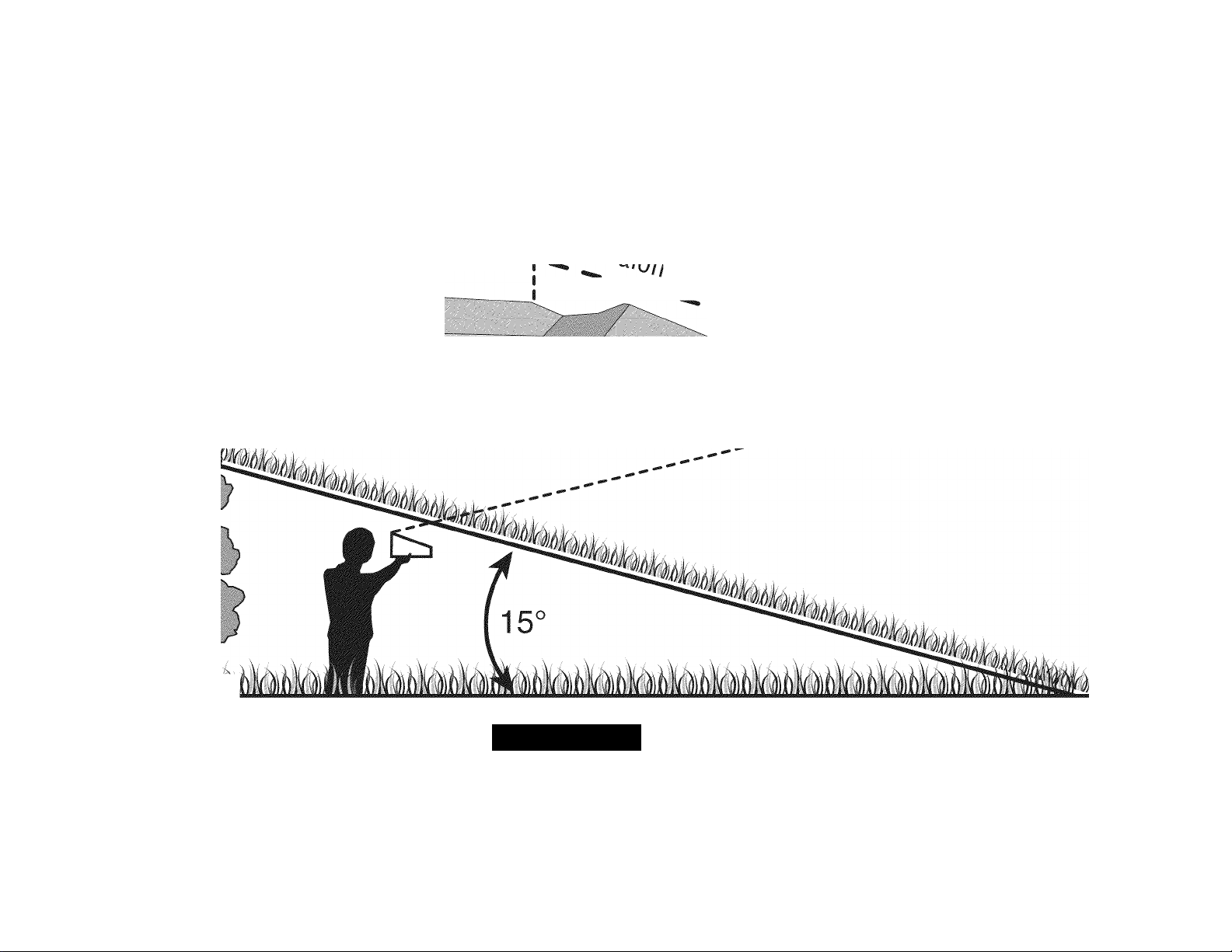
SLOPE OPERATION
Slopes are a major factor related to loss of control and tip-over
accidents which can result in severe injury or death. All slopes require
extra caution. If you cannot back up the slope or it you feel uneasy on
it, do not mow it.
For your safety, use the Slope Guide included as part of this manual
to measure slopes before operating this machine on a sloped or hilly
area. If the slope is greater than 15 degrees as shown on the Slope
Guide, do not operate this machine on that area or serious injury could
result.
Do:
• Mow up and down slopes, not across. Exercise extreme caution
when changing direction on slopes.
• Watch tor holes, ruts, bumps, rocks, or other hidden objects.
Uneven terrain could overturn the machine. Tall grass can hide
obstacles.
• Use slow speed. Choose a low enough speed setting so that
you will not have to stop or shift while on the slope. Tires may
lose traction on slopes even though the brakes are functioning
properly. Always keep machine in gear when going down slopes
to take advantage of engine braking action.
• Follow the manufacturer’s recommendations for wheel weights
or counterweights to improve stability. For recommendations, call
1-800-659-5917.
• Use extra care with grass catchers or other attachments. These
can change the stability of the machine.
• Keep all movement on the slopes slow and gradual. Do not make
sudden changes in speed or direction. Rapid engagement or
braking could cause the front of the machine to lift and rapidly flip
over backwards which could cause serious injury.
• Avoid starting or stopping on a slope. If tires lose traction, disen
gage the blade(s) and proceed slowly straight down the slope.
Do Not:
• Do not turn on slopes unless necessary; then, turn slowly and
gradually downhill, if possible.
• Do not mow near drop-offs, ditches or embankments. The mower
could suddenly turn over if a wheel is over the edge of a cliff,
ditch, or it an edge caves in.
• Do not try to stabilize the machine by putting your foot on the
ground.
• Do not use a grass catcher on steep slopes.
• Do not mow on wet grass. Reduced traction could cause sliding.
• Do not attempt to coast downhill. Over-speeding may cause the
operator to lose control of the machine resulting in serious injury
or death.
• Do not tow heavy pull behind attachments (e.g. loaded dump cart,
lawn roller, etc.) on slopes greater than 5 degrees. When going
down hill, the extra weight tends to push the tractor and may
cause you to loose control, (e.g. tractor may speed up, braking
and steering ability are reduced, attachment may jack-knife and
cause tractor to overturn).
Page 5

SAFETY INSTRUCTIONS
J
CHILDREN
Tragic accidents can occur it the operator is not alert to the presence
of children. Children are often attracted to the machine and the mowing
activity. They do not understand the dangers. Never assume that
children will remain where you last saw them.
• Keep children out of the mowing area and In watchful care of a
responsible adult other than the operator.
• Be alert and turn machine off if a child enters the area.
• Before and while backing, look behind and down for small
children.
• Never carry children, even with the blade(s) shut off. They may
fall off and be seriously Injured or Interfere with safe machine
operation.
• Use extreme care when approaching blind corners, doorways,
shrubs, trees or other objects that may block your vision of a child
who may run Into the machine.
• To avoid back-over accidents, always disengage the cutting
blade(s) before shifting Into Reverse. If equipped, the “Reverse
Caution Mode” (blades operate while machine rides in reverse)
should not be used when children or others are around.
• Keep children away from hot or running engines. They can suffer
bums from a hot muffler.
• Remove key when machine Is unattended to prevent unauthorized
operation.
Never allow children under 14 years of age to operate this machine.
Children 14 and over should read and understand the Instructions and
safe operation practices In this manual and on the machine and should
be trained and supervised by an adult.
TOWING
• Tow only with a machine that has a hitch designed for towing. Do
not attach towed equipment except at the hitch point.
• Follow the manufacturers recommendation for weight limits tor
towed equipment and towing on slopes. For recommendations,
call 1-800-659-5917.
• Never allow children or others In or on towed equipment.
• On slopes, the weight of the towed equipment may cause loss of
traction and loss of control.
• Always use extra caution when towing with a machine capable of
making tight turns (e.g. “zero-turn” ride-on mower). Make wide
turns to avoid jack-knifing.
• Travel slowly and allow extra distance to stop.
• Do not coast downhill.
SERVICE
Safe Handling of Gasoline
To avoid personal injury or property damage use extreme care in
handling gasoline. Gasoline is extremely flammable and the vapors are
explosive. Serious personal injury can occur when gasoline is spilled
on yourself or your clothes which can ignite. Wash your skin and
change clothes immediately.
• Use only an approved gasoline container.
• Never fill containers inside a vehicle or on a truck or trailer bed
with a plastic liner. Always place containers on the ground away
from your vehicle before filling.
• When practical, remove gas-powered equipment from the truck
or trailer and refuel it on the ground. If this is not possible, then
refuel such equipment on a trailer with a portable container, rather
than from a gasoline dispenser nozzle.
• Keep the nozzle in contact with the rim of the fuel tank or
container opening at all times until fueling is complete. Do not use
a nozzle lock-open device.
• Extinguish all cigarettes, cigars, pipes and other sources of
ignition.
• Never fuel machine indoors.
• Never remove gas cap or add fuel while the engine is hot or run
ning. Allow engine to cool at least two minutes before refueling.
• Never over fill fuel tank. Fill tank to no more than Vi inch below
bottom of filler neck to allow space for fuel expansion.
• Replace gasoline cap and tighten securely.
• If gasoline is spilled, wipe it off the engine and equipment. Move
machine to another area. Wait 5 minutes before starting the
engine.
• To reduce fire hazards, keep machine free of grass, leaves, or
other debris build-up. Clean up oil or fuel spillage and remove any
fuel soaked debris.
• Never store the machine or fuel container inside where there is an
open flame, spark or pilot light as on a water heater, space heater,
furnace, clothes dryer or other gas appliances.
• Allow a machine to cool at least five minutes before storing.
Page 6

SAFETY INSTRUCTION
I
General Service
• Never run an engine indoors or in a poorly ventilated area. Engine
exhaust contains carbon monoxide, an odorless, and deadly gas.
• Before cleaning, repairing, or inspecting, make certain the
blade(s) and all moving parts have stopped. Disconnect the spark
plug wire and ground against the engine to prevent unintended
starting.
• Periodically check to make sure the blades come to complete
stop within approximately (5) five seconds after operating the
blade disengagement control. If the blades do not stop within the
this time frame, your machine should be serviced professionally
by an authorized Sears Parts & Repair Center.
• Check brake operation frequently as It Is subjected to wear during
normal operation. Adjust and service as required.
• Check the blade(s) and engine mounting bolts at frequent
Intervals for proper tightness. Also, visually Inspect blade(s)
for damage (e.g., excessive wear, bent, cracked). Replace the
blade(s) with the original equipment manufacturer’s (O.E.M.)
blade(s) only, listed In this manual. Use of parts which do not
meet the original equipment specifications may lead to Improper
performance and compromise safety!
• Mower blades are sharp. Wrap the blade or wear gloves, and use
extra caution when servicing them.
• Keep all nuts, bolts, and screws tight to be sure the equipment Is
In safe working condition.
• Never tamper with the safety interlock system or other safety
devices. Check their proper operation regularly.
• After striking a foreign object, stop the engine, disconnect the
spark plug wire(s) and ground against the engine. Thoroughly
Inspect the machine for any damage. Repair the damage before
starting and operating.
• Never attempt to make adjustments or repairs to the machine
while the engine is running.
• Grass catcher components and the discharge cover are subject
to wear and damage which could expose moving parts or allow
objects to be thrown. For safety protection, frequently check
components and replace immediately with original equipment
manufacturer's (O.E.M.) parts only, listed In this manual. Use of
parts which do not meet the original equipment specifications may
lead to Improper performance and compromise safety!
• Do not change the engine governor settings or over-speed the
engine. The governor controls the maximum safe operating speed
of the engine.
• Maintain or replace safety and instruction labels, as necessary.
• Observe proper disposal laws and regulations for gas, oil, etc. to
protect the environment.
• According to the Consumer Products Safety Commission (CPSC)
and the U.S. Environmental Protection Agency (EPA), this product
has an Average Useful Life of seven (7) years, or 270 hours
of operation. At the end of the Average Useful Life, buy a new
machine or have the machine inspected annually by a Sears or
other qualified service dealer to ensure that all mechanical and
safety systems are working properly and not worn excessively.
Failure to do so can result In accidents, injuries or death.
DO NOT MODIFY ENGINE
To avoid serious injury or death, do not modify engine in any way.
Tampering with the governor setting can lead to a runaway engine and
cause it to operate at unsafe speeds. Never tamper with factory setting
of engine governor.
NOTICE REGARDING EMISSIONS
Engines which are certified to comply with California and federal
EPA emission regulations for SCRE (Small Cff Road Equipment) are
certified to operate on regular unleaded gasoline, and may include
the following emission control systems: Engine Modification (EM) and
Three Way Catalyst (TWC) If so equipped.
SPARK ARRESTOR
AWARNING
This machine is equipped with an internal combustion engine and
should not be used on or near any unimproved forest-covered,
brushcovered or grass-covered land unless the engine's exhaust
system Is equipped with a spark arrester meeting applicable local or
state laws (If any).
If a spark arrester Is used, it should be maintained in effective working
order by the operator. In the State of California the above is required
by law (Section 4442 of the California Public Resources Code). Cther
states may have similar laws. Federal laws apply on federal lands.
A spark arrester for the muffler is available through your nearest Sears
Parts and Repair Service Center.
Page 7

SAFETY INSTRUCTIONS
SAFETY SYMBOLS
This page depicts and describes safety symbols that may appear on this product. Read, understand, and follow all instructions on the machine
before attempting to assemble and operate.
Symbol Description
J
r
READ THE OPERATOR’S MANUAL(S)
Read, understand, and followall instructions in the manual(s) before attempting to assemble and
operate
DANGER— ROTATING BLADES
Never carry passengers. Never carry children, even with the blades off.
DANGER— ROTATING BLADES
Always look down and behind before and while backing to avoid a back-over accident.
WARNING— ROTATING BLADES
Do not put hands or feet near rotating parts or under the cutting deck. Contact with the blade(s)
can amputate hands and feet.
WARNING—THROWN OBJECTS
This machine may pick up and throw and objects which can cause serious personal injury.
WARNING—THROWN OBJECTS
This machine may pick up and throw and objects which can cause serious personal injury.
1#
BYSTANDERS
Keep bystanders, helpers, children and pets at least 75 feet from the machine while it is in
operation.
WARNING— SLOPE OPERATION
Do not operate this machine on a slope greater than 15 degrees.
WARNING—HOT SURFACE
Engine parts, especially the muffler, become extremely hot during operation. Allow engine and
muffler to cool before touching.
DANGER — ROTATING BLADES
To reduce the risk of injury, keep hands and feet away. Do not operate unless discharge cover or grass
catcher is in its proper place. If damaged, replace immediately.
Page 8
Sight and hold this level with a vertical tree...
^ J ^ Fold
or a corner
of
line frpn
a building.
or a fence post
sa /5<
^iope)
f
.••.*.»•■ 4 •. N. S
A WARNING
Use this page as a guide to determine slopes where you may not operate safely.
Do not operate your lawn mower on such slopes. Do not mow on inclines with a slope in excess of 15 degrees (a rise of approximately 2-1/2 feet every 10 feet). A riding mower
could overturn and cause serious injury. Operate riding mowers up and down slopes, never across the face of slopes.
Page 9
SAFETY LABEL
J
ROTATING BLADES CAL
SERIOUS INJURY OR DEATH
> DO NOT MOW WHEN CHILDREN OR OTHERS ,
ARE AROUND
> NEVER CARRY CHILDREN EVEN WITH
SLADE(S)OFF.
• LOOK DOWN AND BEHIND BEFORE
AND WHILE BACKING.
• MOWING IN REVERSE IS NOT RECOMMENDED.
A WARNING
TO AVOID SERIOUS INJURY OR DEATH
GO UP AND DOWN SLOPES, NOT ACROSS.
AVOID SUDDEN TURNS.
DO NOT OPERATE THE UNIT WHERE IT COULD SUP M TIP.
IF MACHINE STOPS GOING UPHILL, STOP RUDE(S)
AND RACK DOWNHILL SLOWLY.
KEEP SAFETY DEVICES (GUARDS, SHIELDS, AND SWITCHES,
ETC.) IN PLACE AND WORKING.
REMOVE OBJECTS THAT COULD BE THROWN BY THE BLABE(S).
KNOW LOCATION AND FUNCTION OF ALL CONTROLS.
BE SURE BUDE(S) AND ENGINE ARE STOPPED BEFORE
PUCING HANDS OR FEET NEAR BUDE(S).
BEFORE LEAVING OPERATOR'S POSITION, DISENGAGE BLADE(S),
ENGAGE PARKING BRAKE, SHUT WF AND REMOVE KEY.
READ OPERATOR'S MANUAL
1. DISENGAGE BLADES/PTO, fPOlVER TAKE OFF}
2. ENGAGE THE TRACTOR’S PARKING BRAKE.
3. SET THROTTLE TO FAST “RABBIT" POSITION AND PULL CHOKE KNOB OUT.
4. TURN KEY TO START ENGINE. AFTER START RELEASE KEY & DEACTIVATE CHOKE.
OPERATING MODES
NORMAL MOWING
/YOU MUST DISENGAGE BLADES PTO. (POIVER TAKE OFFi BEFORE
' TRAVELING IN REVERSE.
________
1. TURN KEY TO REVERSE CAUTION MODE POSITION.
2. DEPRESS REVERSE PUSH BUTTON. (RED INDICATOR LIGHT “ON”)
WHEN RED LIGHT IS “ON” MACHINE CAN BE OPERATED IN REVERSE
WITH MOWER BLADES ENGAGED.
mpommii mowing in reverse is not recommended.
3. AFTER RESUMING FORWARD OPERATION, RETURN KEY TO
“NORMAL MOWING” POSITION.
NOTE: IN BOTH modes, when operator leaves seat, engine will
STOP UNLESS PARKING BRAKE IS SET AND BLADES ARE DISENGAGED.
BRAKE/CLUTCH
(LOCATED ON DRIVERS 1£FT)
SEAT ADJUSTMENT
CAUTION MODE
¡HOW TO operate!
PEDAL
(LOCATED ON DRIVERS RIGHTl
PULL HANDLE UP TO MOVE SEAT FORWARD
TO PUSH RIDER, PULL OUT BOTH RELEASE LEVERS PRESS THE FORWARD
(OR REVERSE) DRIVE PEDAL CONTINUE TO HOLD PEDAL WHILE PUSHING.
31 STEP© Important! Release Bath Rods
. Pull lever out so elbow passes through the large part of the keyhole slotJt. Press aod HOLD either the
. Move lever ioward to the small part of the keyhole slot so that the forward or reverse drive
Ibow is locked agaiost the back of the hitch plate. pedal, cootioue to Hold pedal
Repeat to eogage the other release lever.___________ dowo while pushiog.
posmos I—.
_____^1___________
^'0"w«D
(LOCATIDOS
A danger ^
1l№,1
№.ts that can be thro«« Tf
TO REDUCE THE RISK OF INJURY, DO NOT
OPERATE UNLESS DISCHARGE COVER OR
GRASS CATCHER IS IN ITS PROPER PLACE.
IF DAMAGED, REPLACE IMMEDIATELY.
■7.VÍ-1
KEEP HANDS and FEET AWAY
A DANGER
KEEP HANDS AND FEET AWAY.
DO NOT OPERATE MOWER
UNLESS CHUTE DEFLECTOR
OR ENTIRE GRASS CATCHER IS
ASSEMBLE CHUTE DEFLECTOR TO THIS UNIT BEFORE OPERATING.
IN ITS PROPER PLACE.
®f«'OUS INJURY OR DEATH
AWAY FROM
Awarning
SHIELD MISSING
DO NOT OPERATE.
Page 10
ASSEMBLY
IMPORTANT: Your tractor is shipped with motor oil in the engine.
However, you MUST check the oil level before operating. Refer to the
Service & Maintenance section for instructions on checking the oil
level.
OPENING THE TRACTOR HOOD
To attach the battery cables and check the engine oil level the hood
must be open. Locate the hood lift notch (Refer to Figure 2 on page 11)
at the front/center of the dash panel. Grasping the hood at the notch,
lift and pivot the hood forward to open.
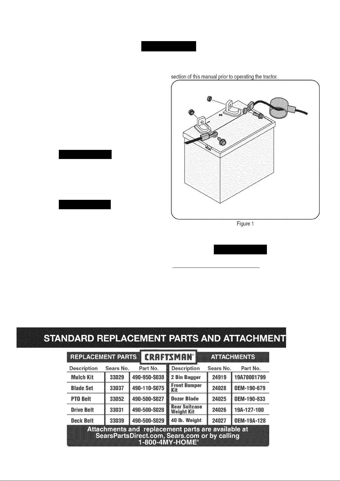
ATTACHING THE BATTERY CABLES
AWARNING
CALIFORNIA PROPOSITION 65
Battery posts, terminals, and related accessories contain lead and
lead compounds, chemicals known to the State of California to
cause cancer and reproductive harm. Wash hands after handling.
A CAUTION
When attaching battery cables, always connect the POSITIVE (Red)
wire to its terminal first, followed by the NEGATIVE (Black) wire.
NOTE: If the battery is put into service after the date shown on top of
battery, charge the battery as instructed in the Service & Maintenance
For shipping reasons, both battery cables on your equipment may
have been left disconnected from the terminals at the factory. To
connect the battery cables, proceed as follows:
NOTE: The positive battery terminal is marked Pos. (+). The negative
battery terminal is marked Neg. (-).
1
.
Remove the plastic cover, it present, from the positive battery
terminal and attach the red cable to the positive battery terminal
(+) with the bolt and hex nut. See Figure 1.
Remove the plastic cover, if present, from the negative battery
terminal and attach the black cable to the negative battery
terminal (-) with the bolt and hex nut. See Figure 1.
Position the red rubber boot over the positive battery terminal to
help protect it from corrosion.
TIRE PRESSURE
AWARNING
Maximum tire pressure under any circumstances is 25 psi. Equal tire
pressure should be maintained at all times.
The tires on your unit may be over-inflated tor shipping purposes.
Reduce the tire pressure before operating the tractor. Recommended
operating tire pressure is approximately 10 p.s.i for the rear tires & 14
p.s.i. for the front tires. Check sidewall of tire for maximum p.s.i.
______________________
I
10
Page 11
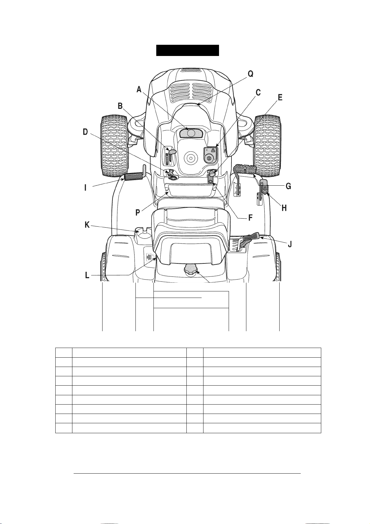
OPERATION
\ 4
______
Figure 2
A Systems Indicator Monitor/ Hour Meter J Deck Lift Lever
B Throttle Control Lever K Cup Holder
C Key Switch Module L Seat Adjustment Lever
D Choke Control Knob M Fuel Fill Cap
E PTC (Blade Engage)Control Knob N IVT Transmission Release levers
F Parking Brake Lever 0 Fuel Level Window
G Forward Control Pedal P Cargo Net
H Reverse Control Pedal
I Brake Pedal
NOTE: Any reference in this manual to the RIGHT or LEFT side of the tractor is observed from operator's position.
if T
—
Hood Lift Notch
Q
Q^l^cnQ
QCLaiLiQ
□ Cr^WCilD
'"M
Meets ANSI Safety Standards
Craftsman Tractors conform to the safety standard of the American National Standards Institute (ANSI).
11
Page 12
OPERATION
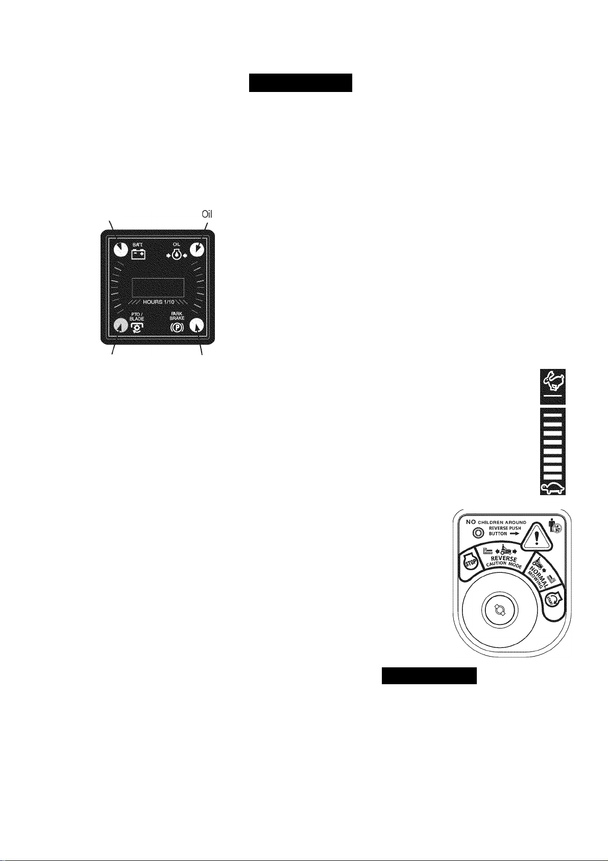
SYSTEMS INDICATOR MONITOR/HOUR
METER
Your tractor is equipped with a Systems Indicator Monitor as shown
in Figure 3. The monitor records the accumulated hours of tractor
operation, and displays the information on the LCD hour meter display
(tenths of an hour - rightmost digit). The monitor also has four indicator
lights that show the status of various functions of the tractor.
Battery
PTO
The system indicator monitor features are as follows:
Parking Brake
Figure 3
LCD Hour Meter Display
The hour meter display is activated when the key switch is turned to
either the “NORMAL MOWING” or the “REVERSE CAUTION MODE”
switch positions. When the key switch is turned to an on position,
the battery indicator light briefly illuminates and the battery voltage is
briefly displayed. The display then changes to the accumulated hours.
NOTE: A record of the actual hours of operation should be kept to
assure maintenance procedures are completed according to the
schedule in this manual.
The Indicator Monitor will also remind the operator of maintenance
intervals for changing the engine oil. The LCD will alternately flash
the recorded hours, “CHG” and “OIL” tor five minutes, after every 50
hours of recorded operation elapse. The maintenance interval lasts for
two hours (from 50-52, 100-102, 150-152, etc.). The LCD will flash as
described for five minutes every time the tractor's engine is started dur
ing this maintenance interval. Follow the oil change intervals provided
in the Service & Maintenance section of this Manual.
Battery Indicator Light
This indicator illuminates when the ignition switch it turned to an ON
position and the engine is not started.
This also illuminates to indicate the battery voltage has dropped below
11.5 (■+-0.5/-1.0) DC volts (the battery voltage is also displayed on the
hour meter). If this indicator and display come on during operation,
check the battery and charging system for possible causes and/or
contact your Sears Parts & Repair Service Center.
Oil Pressure Indicator Light
This warning lamp indicates low engine oil pressure. If this indicator
illuminates, stop the tractor immediately and check the engine oil level.
If the oil level is within the operating range, but the light remains on,
contact your Sears Parts & Repair Service Center.
NOTE: The oil pressure indicator may illuminate when the key switch is
turned to an on position, but should turn off when the engine is started.
PTO (Power Take-Off) Engaged Indicator Light
This indicator illuminates when the key switch is turned to the “START”
position while the PTO knob is in the “ENGAGED” position. Check this
indicator it the engine will not crank with the key switch in the “START”
position. Move the PTO knob to the “DISENGAGED” position.
Brake Engaged Indicator
This indicator illuminates when the key switch is turned to the “START”
position and the brake pedal is not fully depressed. Check this
indicator it the engine will not crank with the key switch in the “START”
position. If necessary, fully depress the brake pedal.
THROTTLE CONTROL LEVER
The throttle control lever controls the speed of
the engine. When set in a given position, the
throttle will maintain a uniform engine speed.
IMPORTANT: When operating the tractor with
the cutting deck engaged, the throttle control
lever must always be in the FAST (rabbit)
position.
Fast
Position
Slow
Position
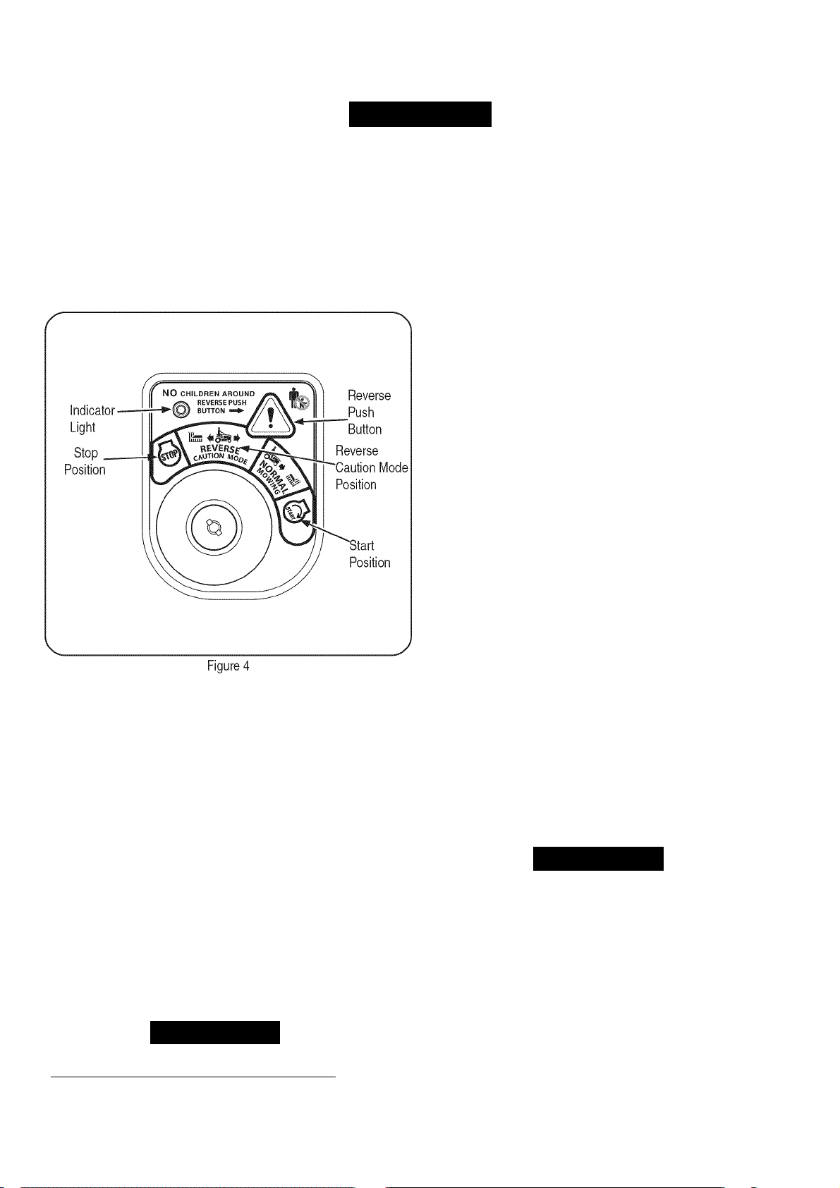
KEY SWITCH MODULE
The key switch module is used to
start and stop the engine. It is also
used to activate the Reverse Caution
Mode (blades operate while riding
in reverse). Insert key into the key
switch module and turn clockwise to
the START position. Release the key
into the normal mowing position once
engine has started.
To stop the engine, turn the ignition
key counterclockwise to the STOP
position.
V
Awarning
Never leave a running machine unattended. Always disengage PTO,
set parking brake, stop engine and remove key to prevent unintended
starting.
IMPORTANT: Prior to operating the tractor, refer to both “Safety
Interlock System” on page 14 and “Starting The Engine” on page 15
of this manual for detailed instructions regarding the Ignition Switch
Module and operating the tractor in REVERSE CAUTION MODE.
12
Page 13

CHOKE CONTROL
The choke control knob is located on the lower left side of the dash
panel and is activated by pulling outward. Activating the choke control
closes the choke plate on the carburetor and aids in starting the
engine.
PTO (BLADE ENGAGE) CON
TROL KNOB
To engage the electric PTO and provide power to
the cutting deck, pull outward on the PTO control
knob. Push the knob inward to disengage the PTO
and stop the cutting deck.
NOTE: The PTO Control Knob must be in the
disengaged (OFF) position when starting the
engine.
rfo^
* 6
S
O
.OFF
HFl
tractor.
DECK LIFT LEVER
The deck lift lever is located in the right fender and is used to change
the cutting height of the mower deck. The cutting heights range from
1-1/2” to 4”. Each of the six index notches represent an approximately
1/2” adjustment to the deck height.
1. To use, grasp the lift lever handle and pull slightly upward (rear
ward) while pivoting the lever inward and out of its index notch.
2. Move the lift lever as necessary to place in the notch best suited
for your application.
After changing the cutting height of the deck, you must check the
position of the deck front gauge wheels. They should be approximately
I
y2-inch above the ground when the tractor is on a smooth, flat surface
such as a driveway. Refer to “Service & Maintenance” later in this
manual.
PARKING BRAKE LEVER
NOTE: The parking brake must be set it the operator
leaves the seat with the engine running; otherwise the
engine will automatically shut off.
1
.
To set the parking brake, fully depress the brake
pedal and push the bottom of parking brake lever
inward. See the image to the right for parking brake
identification. Hold the lever in while removing your J
foot from the brake pedal. Both parking brake lever
and brake pedal will stay depressed.
To release the parking brake, depress the brake pedal slightly.
The parking brake lever will then return to its original position.
IMPORTANT: Always set the parking brake when leaving the tractor
unattended.
(©)
ñ
FORWARD CONTROL PEDAL
The forward control pedal is located on the right side of the tractor, at
the front of the right running board. Depress the forward control pedal
to cause the tractor to travel in the forward direction. The forward
ground speed of the tractor is directly affected by the distance the
pedal is depressed. The further the pedal is depressed, the faster the
tractor will travel. The tractor will slow and the pedal will return to its
original position when released.
REVERSE CONTROL PEDAL
The reverse control pedal is located in the right front running board
rearward of the forward control pedal. Depress the reverse control
pedal to cause the tractor to travel in reverse. The further the pedal is
depressed, the faster the tractor will travel. The tractor will slow and
the pedal will return to its original position when released.
CUP HOLDER
The tractor’s cup holder is located on the fender to the left of the seat.
SEAT ADJUSTMENT LEVER
The seat adjustment lever is on the left side of the seat. Use this lever
to adjust the seat forward or rearward to a comfortable operating
position. See the “Service & Maintenance” section later in this manual
for instructions.
FUEL FILL CAP AND FUEL LEVEL WINDOW
The fuel fill cap is located in the center of the rear fender. Pivot
the seat forward to fully access the fuel fill cap and fill the fuel
tank.
1. Turn the fill cap approximately 1 /4 turn and pull upward to
remove.
2. Push the cap downward on the fuel tank fill neck and turn
1/4 turn clockwise to tighten.
The level of fuel in the fuel tank can be viewed through the fuel
level window in the rear hitch plate.
CARGO NET
Conveniently located on the tractor’s dash panel, the cargo net can be
used to store personal items while operating the lawn tractor.
IVT (INFINITELY VARIABLE TRANSMISSION) RELEASE LEVERS
The IVT transmission release levers are located at the back of the
tractor above the rear hitch plate. When engaged, these levers open
a dump valve in each transmission which allows the tractor to be
manually pushed short distances. See “Moving the Tractor Manually”
later in this section for instructions.
13
Page 14

OPERATION
Awarning
Avoid Serious Injury or Death
Go up and down slopes, not across.
Avoid sudden turns.
Do not operate the unit where it could slip or tip.
If machine stops going uphill, stop blades and back downhill
slowly.
Do not mow when children or others are around.
Never carry children, even with blades off.
Look down and behind before and while backing.
Keep safety devices (guards, shields, and switches) in place
and working.
Remove objects that could be thrown by the blades.
Know location and function of all controls.
Be sure blades and engine are stopped before placing hands or
feet near blades.
Before leaving operator’s position, stop tractor, disengage
blades, engage parking brake, shut engine off, and remove key.
Read Operator’s Manual
OIL AND GAS FILL-UP
Oil
IMPORTANT: Your tractor is shipped with motor oil in the engine.
However, you MUST check the oil level before operating. See the
“Service and Maintenance” section.
Gasoline
Awarning
Use extreme care when handling gasoline. Gasoline is extremely
flammable and the vapors are explosive. Never fuel machine
indoors or while the engine is hot or running. Extinguish cigarettes,
cigars, pipes, and other sources of ignition.
NOTE : Purchase gasoline in small quantities. Do not use gasoline left
over from the previous season, to minimize gum deposits in the fuel
system.
Do not overfill fuel tank. Fill tank to no more than 1/2 inch below
bottom of filler neck to allow space for fuel expansion.
Never remove gas cap or add fuel while the engine is hot or run
ning. Allow engine to cool at least two minutes before refueling.
If gasoline is spilled, wipe it off the engine and equipment. Move
machine to another area. Wait 5 minutes before starting the
engine.
Turn the engine off and let engine cool at least 2 minutes before
removing the fuel cap. The gasoline tank is under the rear fender,
with the fuel fill cap located in the center of the rear fender.
The fuel cap is tethered to the tractor to prevent its loss. Do not
attempt to remove the cap from the tractor.
Fill the fuel tank with gasoline.
Reinstall the fuel cap.
SAFETY INTERLOCK SYSTEM
The safety interlock system is designed for safe operation of the trac
tor. If this system should ever malfunction, do not operate the tractor,
immediately contact your Sears Parts & Repair Service Center.
• The safety interlock system prevents the engine from starting
unless the parking brake is engaged and the PTO knob is in the
disengaged (OFF) position.
• The safety interlock system will automatically shut off the engine it
the operator leaves the seat before engaging the parking brake.
• The safety interlock system will automatically shut off the engine
it the operator leaves the tractor's seat with the PTO (Blade
Engage) knob engaged, regardless of whether the parking brake
is engaged.
• With the ignition key in the NORMAL MOWING position, the
electric PTO clutch will automatically shut off it the PTO knob is in
the engaged (ON) position and the drive pedal is depressed for
Reverse travel.
Awarning
Tampering with or attempting to bypass the Safety Interlock Switches
in any way will void your tractor’s warranty. Do not operate the tractor
it the interlock system is malfunctioning.
REVERSE CAUTION MODE
• This engine is certified to operate on unleaded gasoline. For best
results, fill the fuel tank with only clean, fresh, unleaded gasoline
with a pump sticker octane rating of 87 or higher.
• Gasohol (up to 10% ethyl alcohol, 90% unleaded gasoline by
volume) is an approved fuel. Other gasoline/alcohol blends, such
as E85, are not approved.
• Methyl Tertiary Butyl Ether (MTBE) and unleaded gasoline blends
(up to a maximum of 15% MTBE by volume) are approved fuels.
Other gasoline/ether blends are not approved.
• Fill fuel tank outdoors or in well-ventilated area.
Awarning
Use extreme caution while operating the tractor in the REVERSE
CAUTION MODE. Always look down and behind before and while
backing. Do not operate the tractor when children or others are
around. Stop the tractor immediately it someone enters the area.
The REVERSE CAUTION MODE position of the key switch module
allows the tractor to be operated in reverse with the blades (PTO)
engaged.
14
Page 15
OPERATION
J
IMPORTANT: Mowing in reverse is not recommended.
To use the REVERSE CAUTION MODE:
IMPORTANT: The operator MUST be seated in the tractor seat.
1. Start engine as instructed in the Starting The Engine section.
2. Turn the key from the NORMAL MOWING (Green) position to the
REVERSE CAUTION MODE (Yellow) position of the key switch
module. See Figure 4.
3. Depress the REVERSE PUSH BUTTON (Orange, Triangular
Button) at the top, right corner of the key switch module. The red
indicator light at the top, left corner of the key switch module will
be ON while activated. See Figure 4.
4. Once activated (indicator light ON), the tractor can be driven in
reverse with the cutting blades (PTO) engaged.
5. Always look down and behind before and while backing to make
sure no children are around.
6. After resuming forward motion, return the key to the NORMAL
MOWING position.
IMPORTANT: The REVERSE CAUTION MODE will remain activated
until:
a. The key is placed in either the NORMAL MOWING position
or STOP position.
b. The operator leaves the seat. Follow the previous instruc
tions to re-activate.
STARTING THE ENGINE
Awarning
Do not operate the tractor if the interlock system is malfunctioning.
This system was designed for your safety and protection.
_________
1. Insert the tractor key into the key switch module.
2. Disengage the PTO (Blade Engage) knob.
3. Engage the tractor’s parking brake.
4. Pull the choke control knob outward into the full choke position (a
warm engine may not require choking).
5. Move the throttle control lever to the FAST position.
6. Turn the ignition key clockwise to the START position. After
the engine starts, release the key. It will return to the NORMAL
MOWING position.
IMPORTANT: Do not hold the key in the START position for longer
than ten seconds at a time. Doing so may cause damage to your
engine's electric starter.
7. After the engine starts, gradually push the choke knob fully inward
as the engine warms up.
NOTE: Do not use the choke control to enrich the fuel mixture, except
as necessary to start and warm up the engine.
IMPORTANT
Do not leave the seat of the tractor witfiout
1. Disengaging PTO knob
2. Depressing brake pedal
3. Engaging parking brake
If leaving the tractor unattended, also turn the
ignition key off and remove the key.
Avoid sudden starts, excessive speed and sudden
stops while driving the tractor.
Q/“'. r!/“'.? /^.r! in OYnoCC n.f 1
s not mow on slope in excess of 15 degrees (a rise
of
approximately 2-1./2 feet every 10 feet).
.........
........
y“ •■■ - )■ 1^/
Keep hands and feet away from the opening of the
cutting deck
Plan your mowing pattern lo avoia aiscnarge or
materials toward roads, sidev\/alks, bystanders and
the like. Also, avoid discharging material against
a wall or obstruction which may cause discharged
material to ricochet back toward the operator.
STOPPING THE ENGINE
Awarning
If you strike a foreign object, stop the engine and disconnect the
spark plug wire(s). Thoroughly inspect the machine tor any
damage. Repair the damage before restarting and operating.
1. If the blades are engaged, disengage the PTO.
2. Move the throttle control lever to midway between the half and fi
throttle. Then turn the ignition key counterclockwise to the OFF
position.
3. Remove the key from the ignition switch to prevent unintended
starting.
15
Page 16
OPERATION
I
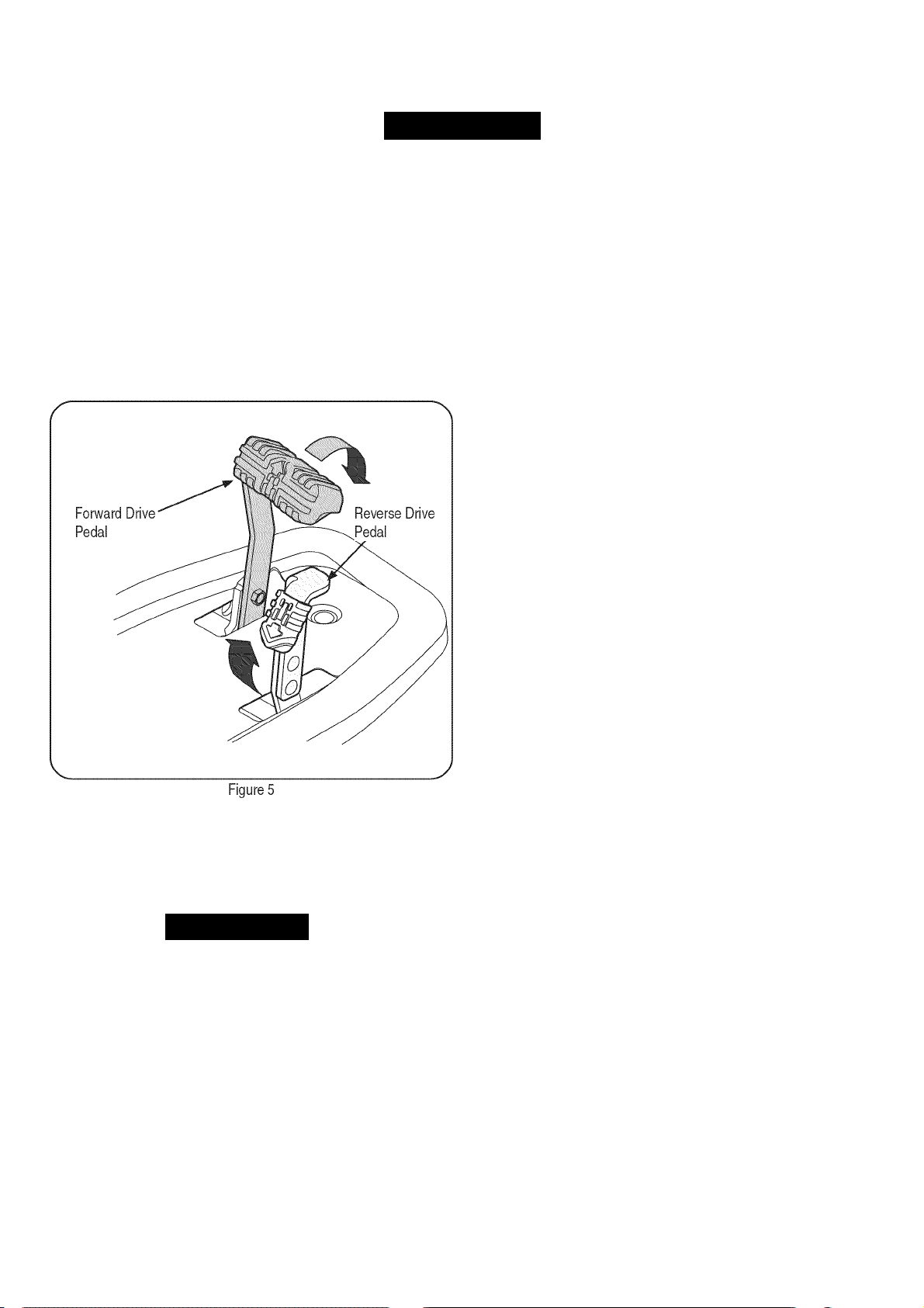
DRIVING THE TRACTOR
IMPORTANT: Avoid sudden starts, excessive speed and sudden
stops.
NOTE: Your Revolution tractor is equipped with an innovative drive
system. It is normal for some forward movement of the tractor to occur
when the brake is released.
1. Briefly depress the brake pedal to release the parking brake.
Move the throttle lever into the FAST (rabbit) position.
2. To travel forward: Slowly depress the forward drive control pedal
until the desired speed is achieved. See Figure 5.
1. The steering wheel rotates approximately two full turns from its
stopping point on one side to its stopping point on the other, with
the center position being the straight ahead position.
2. Minor turns of the steering wheel from the center position
(approximately 10° to 15°) turn only the front axles and will result
in wider turns.
3. Increasing the turn of the steering wheel (beyond 10“-15°) results
in increasingly tighter turns. As the steering mechanism turns the
front wheels, it also changes the position of the transmission drive
control linkage to slow down the inner rear wheel in the turn, and
adjusts the speed of the outer wheel as necessary to complete
the desired turn. Turn the steering wheel back to the center
position as the turn is completed.
NOTE: It is not necessary to release the drive pedal when making a
turn. The change to the transmission linkage occurs regardless of how
far the drive pedal is depressed. When the steering wheel is straight
ened, the tractor will return to the speed set by the drive pedal.
4. Turning the steering wheel fully to its stop in either direction
will fully turn the front wheels, reverse the direction of the inner
wheel and adjust the outer wheel speed to execute a zero turn in
the chosen direction. Turn the steering wheel back to the center
position as the turn is completed.
NOTE: The steering wheel has to be turned all the way UNTIL IT
STOPS to complete a zero turn. As the steering wheel is turned further
toward its stop, the effort needed to turn the steering wheel increases.
To travel in reverse: Check that the area behind is clear, then
slowly depress the reverse drive control pedal until the desired
speed is achieved. See Figure 5.
Release the depressed drive pedal and depress the brake pedal
to stop the tractor.
Awarning
Do not leave the seat of the tractor without first placing the PTO/
Blade Engage knob in the disengaged (OFF) position and engaging
the parking brake. If leaving the tractor unattended, also turn the
engine off and remove the ignition key.
STEERING THE TRACTOR
Your Revolution tractor is equipped with an innovative steering system.
Turning the steering wheel not only turns the front wheels, but also
adjusts the position of the drive control linkage of the transmissions
that drive the tractor. This steering system allows you to vary the radius
of turns from a normal wide U-turn down to a zero turn (a tight “aboutface” turn). Some practice may be needed to become accustomed to
the steering of your tractor. The steering works as follows:
IMPORTANT: Making tight or zero turns on grass will greatly increase
the potential for damage to the turf.
DRIVING ON SLOPES
IMPORTANT: Refer to the SLOPE GAUGE on page 8 to help deter
mine slopes where you may operate the tractor safely.
• Mow up and down slopes, never across.
• Watch tor holes, ruts, bumps, rocks, or other hidden objects.
Uneven terrain could overturn the machine. Tall grass can hide
obstacles.
• Avoid turns when driving on a slope. If a turn must be made, turn
downhill on the slope. Turning uphill increases the possibility of a
tractor rollover.
• Avoid stopping when driving up a slope. If it is necessary to stop
while driving up a slope, start up smoothly and carefully to reduce
the possibility of flipping the tractor over backward.
ENGAGING THE PARKING BRAKE
NOTE: The parking brake must be set if the operator leaves the seat
with the engine running or the engine will automatically shut off.
To set the parking brake:
1. Press the brake pedal completely down with your left foot and
hold it that position.
2. Push the parking brake lever downward and hold it in that
position.
16
Page 17
OPERATION
J
3. Remove your foot from the brake pedal.
4. Release pressure from the parking brake lever.
After completing step 3, the brake pedal should remain In the down
position. It it doesn’t, the parking brake is not engaged. Repeat steps
1-4 to engage the parking brake.
To disengage the parking brake, lightly press the brake pedal.
AWARNING
Never leave a running machine unattended. Always disengage PTO,
set parking brake, stop engine and remove key to prevent unintended
starting.
ENGAGING THE PTO
Engaging the PTO transfers power to the cutting deck or other
(separately available) attachments. To engage the PTO:
1. Move the throttle control lever to the FAST (rabbit) position.
2. Pull the PTO/Blade Engage knob outward into the engaged (ON)
position.
NOTE: Always operate the tractor with the throttle lever in the FAST
(rabbit) position for the most efficient use of the cutting deck or other
(separately available) PTO driven attachments.
MOWING
2. Shut engine off and remove the key.
Doing so will minimize the possibility of having your lawn “browned” by
hot exhaust from your tractor’s running engine.
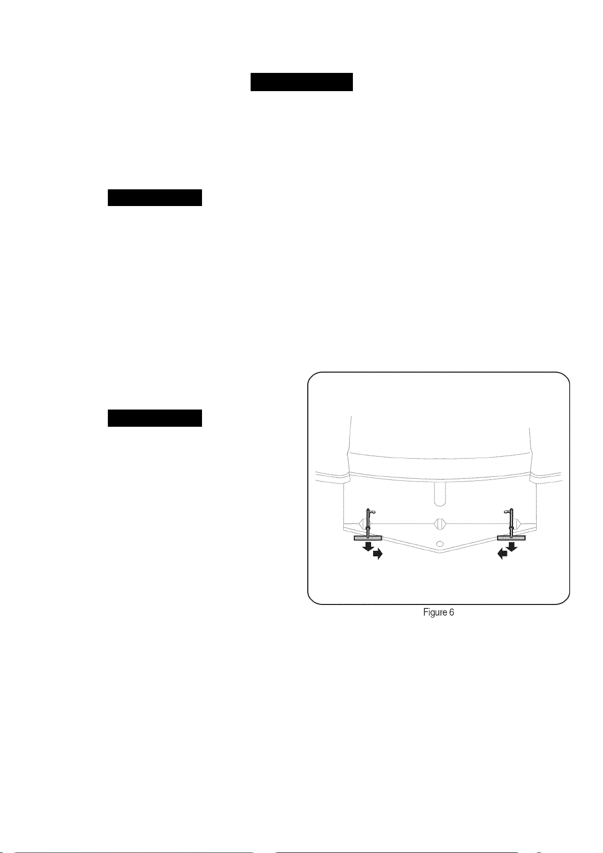
MOVING THE TRACTOR MANUALLY
If tor any reason the tractor will not drive or you wish to move the
tractor, engage the two transmission release levers to manually move
the tractor short distances.
IMPORTANT: Never tow or drag the tractor with the rear wheels on the
ground. Even with the release levers engaged. Doing so will damage
the transmissions.
To engage a release lever:
1. Pull the lever rearward so that the elbow passes through the
larger/rounded part of the keyhole slot.
With the elbow of the lever outside (rearward) of the hitch plate,
push the lever inward in the small part of the keyhole slot so that
lever’s elbow is locked against the back of the hitch plate.
Repeat to engage the other release lever to allow the tractor to be
manually moved. See Figure 6.
AWARNING
To help avoid blade contact or a thrown object injury, keep bystand
ers, helpers, children and pets at least 75 feet from the machine
while it is in operation. Stop machine it anyone enters the area.
This tractor is equipped with one of Craftsman’s high quality cutting
decks. The following information will be helpful when using the cutting
deck with your tractor.
• Do not mow at high ground speed, especially it a mulch kit or
grass collector is installed.
• For best results it is recommended that the first two laps be cut
with the discharge thrown towards the center. After the first two
laps, reverse the direction to throw the discharge to the outside
for the balance of cutting. This will give a better appearance to the
lawn.
• Do not cut the grass too short. Short grass invites weed growth
and yellows quickly in dry weather.
• Mowing should always be done with the engine at full throttle.
• Under heavier conditions it may be necessary to go back over the
cut area a second time to get a clean cut.
• Do not attempt to mow heavy brush and weeds and extremely tall
grass. Your tractor is designed to mow lawns, not clear brush.
• Keep the blades sharp and replace the blades when worn. Refer
to the “Service & Maintenance” section of this manual for proper
blade sharpening instructions.
IMPORTANT: When stopping the tractor for any reason while on a
grass surface, always:
1. Engage the parking brake.
* •
4. To move the tractor manually, the brake must be disengaged by
releasing the parking brake and depressing the forward or reverse
drive pedal. Continue to hold the drive pedal while pushing.
5. To disengage, move the lever to align its elbow with the larger/
rounded part of the keyhole slot and release the lever back
through the hitch plate.
NOTE: The transmission will NOT engage when the release lever is
pulled out. Return the lever to its normal position prior to operating the
tractor.
HEADLIGHTS
The tractor headlights are turned on whenever the ignition switch is
turned to either of the run positions.
17
Page 18

SERVICE AND MAINTENANCE
MAINTENANCE SCHEDULE
Awarning
Before performing any type of maintenance/service, disengage all
controls and stop the engine. Wait until all moving parts have come to
a complete stop. Disconnect spark plug wire and ground it against the
engine to prevent unintended starting. Always wear safety glasses during
operation or while performing any adjustments or repairs.
Follow the maintenance schedule given below. This chart describes
service guidelines only. Use the Service Log column to keep track of
completed maintenance tasks. To locate the nearest Sears Service
Center or to schedule service, simply contact Sears at
1-800-4-MY-HOME®.
Interval
Before Each Use 1. Engine oil level 1. Check
2. Muffler area and controls 2. Clean
3. Finger guard 3. Clean
In the First Five Flours 1. Engine Oil 1. Change
Every 10 Flours 1. Flood/ Dash air vents 1. Clean
2. Battery terminals 2. Clean
3. Deck spindles and idler 3. Lubricate
bracket
Every 25 hours 1. Air filter’s precleaner* 1. Clean
2. Air filter* 2. Clean
3. Mid steering arms, pivot 3. Lubricate
shafts, and axles
4. Front wheel bearings 4. Lubricate
5. Front deck wheels 5. Lubricate
Every 50 hours 1. Engine oil/ Oil filter 1. Change/ Replace
2. Muffler 2. Check
Annually 1. Air filter 1. Replace
2. Air filter’s pre-cleaner 2. Replace
3. Spark plug 3. Replace
4. Air cooling system* 4. Clean
5. Fuel filter 5. Replace
6. Steering Gears 6. Clean
7. Rear Wheels 7. Remove and grease axles
Before Storage 1. Flood/ Dash air vents 1. Clean
2. Battery terminals 2. Clean
3. Mid steering arms, pivot 3. Lubricate
shafts, and axles
4. Front wheel bearings 4. Lubricate
5. Front deck wheels 5. Lubricate
6. Deck spindles and idler 6. Lubricate
bracket
7. Pedal pivot points 7. Lubricate
‘Service more frequently under dusty conditions.
Item
Service Service Log
AWARNING
Before performing any maintenance or repairs, disengage the PTC,
engage the parking brake, stop the engine and remove the key to
prevent unintended starting.
Awarning
If the engine has been recently run, the engine, muffler and sur
rounding metal surfaces will be hot and can cause burns to the skin.
Exercise caution to avoid burns.
18
Page 19
SERVICE AND MAINTENANCE
J
ENGINE MAINTENANCE
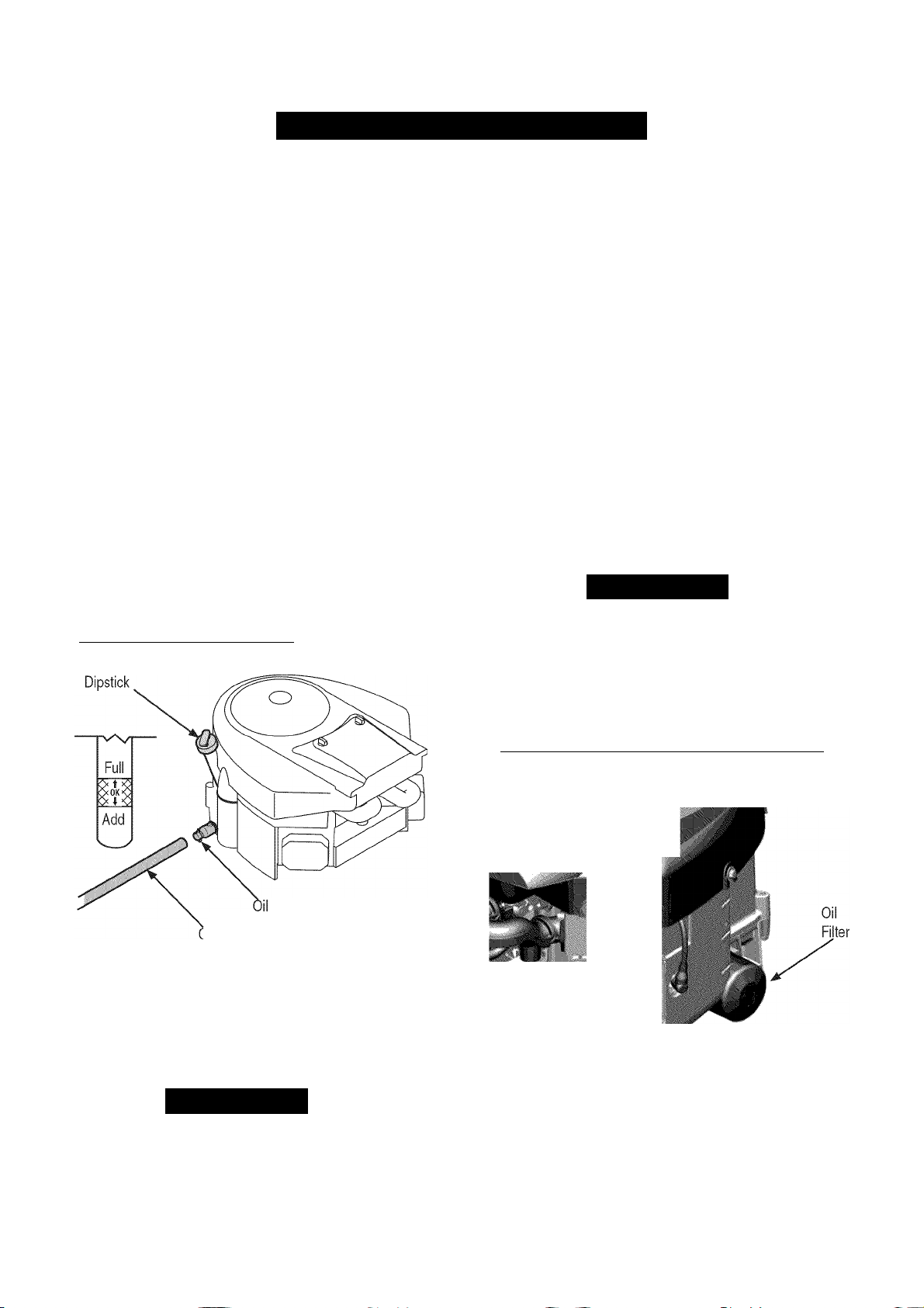
Checking the Engine Oil
Only use high quality detergent oil rated with API service classification
SF, SG, SH, or SJ. Select the oil's SAE viscosity grade according to
the expected operating temperature. Follow the chart below.
/Colder
5W20
■32°F
SAE30
•-WarmeA
Oil Viscosity Chart
Although multi-viscosity oils (5W20,10W30, etc.) improve starting
in cold weather, they will result in increased oil consumption when
used above 32°F. Check your engine oil level more frequently to avoid
possible engine damage from running low on oil.
To check the engine oil, proceed as follows:
1.
Ensure that the tractor is on a level surface.
2.
Clean the oil fill area of any debris.
3.
Remove the dipstick and wipe with a clean cloth.
4.
Insert and tighten dipstick.
5.
Remove the dipstick and check the oil level. It should be at the
Full mark on the dipstick. See Figure 7.____________________
Changing Engine Oil
The engine oil should be changed in the first 5 hours and then every
50 hours or once a season. To change the engine oil, proceed as
follows:
1. With engine CFF but still warm, disconnect spark plug wire and
keep it away from spark plug.
2. Pop off the protective cap on the end of the oil drain valve to
expose the drain port. See Figure 7.
3. Remove the oil fill cap/dipstick from the oil fill tube. See Figure 7.
4. Push the oil drain hose (packed with this manual) onto the oil
drain port. Route the opposite end of the hose into an appropriate
oil collection container with a capacity great enough to collect the
used oil.
5. Release the valve by twisting and pulling the valve out. The oil will
begin to drain out of the engine.
6. After the oil has finished draining, press the two tabs inward and
push the oil drain valve back in to lock the valve closed. Remove
the hose, twist and push in to lock valve, and re-cap the end of
the oil drain valve to keep debris from entering the drain port.
7. Refill the engine with new motor oil until the oil level on the
dipstick reads FULL. Replace the oil fill cap/dipstick.
A CAUTION
Used oil is a hazardous waste product. Dispose of used oil properly.
Do not discard with household waste. Check with your local authori
ties or Sears Service Center for safe disposal/recycling facilities.
Drain
Jil Drain
Hose
If low, add oil slowly into the engine oil fill. Do not overfill. After
adding oil, wait one minute and then recheck the oil level.
Replace and tighten dipstick.
Valve
Figure 7
A CAUTION
Do not overfill. Cverfilling with oil may cause the engine to not start,
hard starting, or engine smoking. If over the FULL mark on the
dipstick, drain oil to reduce oil level to FULL mark on dipstick.
Changing the Oil Filter
1. Drain the oil from the engine as described above.
2. Remove the oil filter and dispose of properly. See Figure 8.
m
■
■
»
Figure 8
Before you install the new oil filter, lightly lubricate the oil filter
gasket with fresh, clean oil.
4.
Install the oil filter by hand until the gasket contacts the oil filter
adapter, then tighten the oil filter 1/2 to 3/4 turns.
19
Page 20
SERVICE AND MAINTENANCE
5. Add oil as described above.
6. Start and run the engine. As the engine warms up, check for oil
leaks.
7. Stop the engine and check the oil level. It should be at the FULL
mark on the dipstick.
Fuel Filter
AWARNING
Gasoline and its vapors are extremely flammable and explosive. Fire
or explosion can cause severe burns or death.____________________
Keep gasoline away from sparks, open flames, pilot lights, heat,
and other ignition sources.
Check fuel lines, tank, cap, and fittings frequently for cracks or
leaks. Replace if necessary.
Before replacing the fuel filter, drain the fuel tank or close the fuel
shut-off valve.
Replacement parts must be the same and installed in the same
position as the original parts.
If fuel spills, wait until It evaporates before starting engine.
Before replacing the fuel filter, drain the fuel tank or close the fuel
shut-off valve. Otherwise, fuel can leak out and cause a tire or
explosion.
Use pliers to squeeze tabs on the clamps, then slide the clamps
away from the fuel filter. Twist and pull the fuel lines off of the fuel
Air Cleaner
AWARNING
If filters, or covers are not installed correctly serious injury or death
could result from backfire. Do not attempt to start the engine with
them removed.
A CAUTION
Do not use pressurized air or solvents to clean the air cleaner
cartridge.
Remove the air filter cover.
To remove the air filter, lift the end of the filter. See Figure 10.
Cover
Pre-cleaner
Filter
A
3. Check the fuel lines for cracks or leaks. Replace it necessary.
4. Replace the fuel filter with an original equipment replacement
filter.
5. Secure the fuel lines with the clamps.
Figure 10
Remove the pre-cleaner from the filter.
To loosen debris, gently tap the filter on a hard surface. If the filter
is excessively dirty, replace with a new filter.
Wash the pre-cleaner in liquid detergent and water. Allow It to
thoroughly air dry. Do not oil the pre-cleaner.
6.
Assemble the dry pre-cleaner to the filter.
7.
Install the filter into the engine base and push down until the filter
snaps in place.
Install the cover.
20
Page 21
SERVICE AND MAINTENANCE
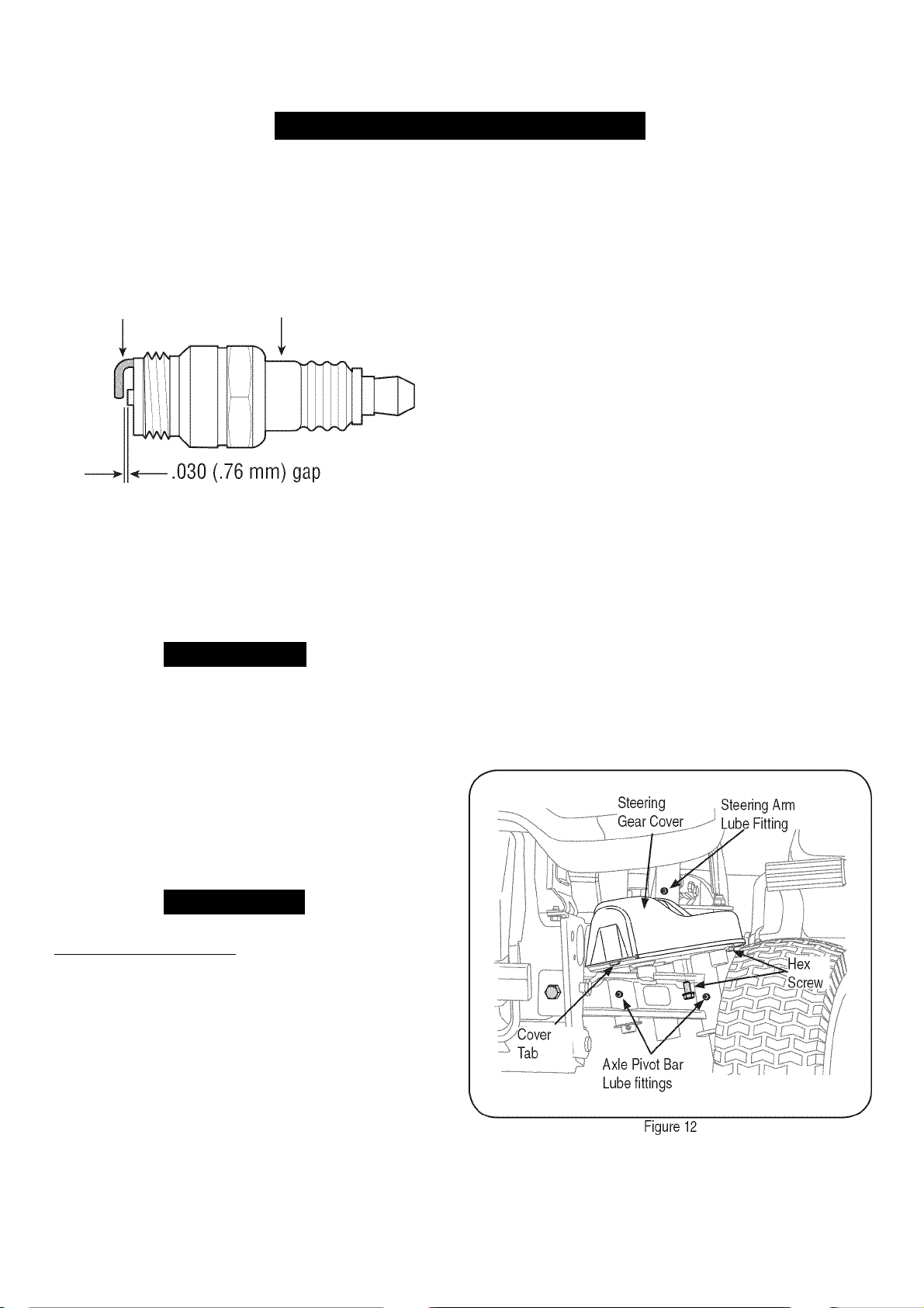
Spark Plug
1. Clean area around the spark plug base. Do not sandblast spark
plug. Spark plug should be cleaned by scraping or wire brushing
and washing with a commercial solvent
2. Remove and inspect the spark plug. Check gap to make sure it is
set at .030”. See Figure 11.
Electrode
3. Replace the spark plug (Champion® RC12YC) once a season .
Muffler
• Inspect muffler periodically, and replace if necessary. Replace
ment parts for the muffler must be the same and installed in the
same position as the original parts.
Awarning
Temperature of muffler and nearby engine areas may exceed 150° F
(65°C). Avoid contact with these areas.
Clean Engine
• Daily or before every use, clean grass, chaff or accumulated
debris from engine. Keep linkage, spring, and controls clean.
• Keep area around and behind muffler free of any combustible
debris.
• Keeping engine clean allows air movement around engine.
• Engine parts should be kept clean to reduce the risk of overheat
ing and ignition of accumulated debris.
Porcelain
Figure 11
J
Deck Spindles and Idler Bracket
Lubricate the deck spindles and idler bracket with a No. 2 multipurpose
lithium grease after every 10 hours of operation.
• The deck spindle lube fittings are in the spindle housings, and
can only be accessed from the underside of the deck.
• Lubricate the idler bracket through the lube fitting in the top of the
shoulder bolt. Use a pressure grease gun to lubricate the spindles
and idler bracket.
Pivot Points & Linkage
Lubricate all the pivot points on the drive system, parking brake and lift
linkage at least once a season with light oil.
Rear Wheels
The rear wheels should be removed from the axles once a season.
Lubricate the axles and the rims well with an all purpose grease before
re-installing them.
IVT Transmission
The IVT transmission is sealed at the factory and is maintenance free.
The fluid level cannot be checked and cannot be changed. Keep the
area around the transmission cooling fan free of grass and debris at all
times.
Steering
The steering arms, pivot shafts, and axles must be lubricated it ever
the steering effort increases, or after every 25 hours of operation.
Lubricate using a pressure grease gun and a No. 2 multipurpose
lithium grease.
1. Apply grease through the lube fitting on the RFI and LH (right
hand and left hand, from operator's position) steering arms which
are located at rearward end of the two steering drag links. See
Figure 12.
A CAUTION
Do not use water to clean engine parts. Water could contaminate fuel
system. Use a brush or dry cloth.
Carburetor Adjustment
• The carburetor on this engine is not adjustable.
LUBRICATION
Front Wheel Bearings
Lubricate the front wheel bearings with a No. 2 multipurpose lithium
grease after every 25 hours of operation. The lube fittings are located
in the rim hub inside each front wheel.
______________________________
Locate the lube fittings for the pivot shaft and axle on the front of
one end of the axle pivot bar. Apply grease through the two lube
fittings, then repeat to lubricate the other end of the pivot bar. See
Figure 12.
21
Page 22
SERVICE AND MAINTENANCE
TIRES
Awarning
Never exceed the maximum inflation pressure shown on the sidewall
of tire. Refer to the tire sidewall for exact tire manufacturer’s recom
mended or maximum psi. Do not overinflate.
The recommended operating tire pressure is:
• Approximately 10 psi for the rear tires
• Approximately 14 psi for the front tires
IMPORTANT: Uneven tire pressure could cause the cutting deck to
mow unevenly.
CLEANING STEERING GEARS
Once a year, or it a tight spot is experienced when turning the steering
wheel, remove the steering gear cover on each end of the pivot bar
and clean the two steering gears.
1. From beneath the cover base plate on each end of the pivot bar,
remove the three hex screws securing the steering gear cover.
Remove the covers and clean the gears. It is not necessary to
lubricate the gears. Refer to Figure 12.
2. Insert the tab of the LH steering gear cover into the square hole
in the LH base plate, position the cover, and secure with the three
hex screws. Do not over tighten. Repeat to install the cover on the
RH side.
CLEANING THE TRACTOR AND DECK
Any fuel or oil spilled on the machine should be wiped off promptly. Do
NOT allow debris to accumulate around the deck pulleys or any other
part of the machine.
Periodically remove the belt covers and remove any accumulated
grass clippings from around the spindle pulleys and the deck belt.
IMPORTANT: The use of a pressure washer to clean your tractor is
NOT recommended. It may cause damage to electrical components,
spindles, pulleys, bearings or the engine.
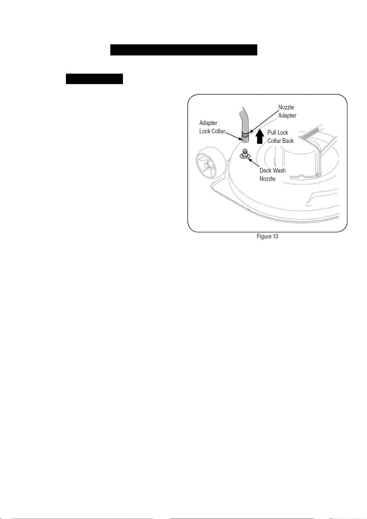
4. Pull back the lock collar of the nozzle adapter and push the
adapter onto the deck wash nozzle at the left end of the mower
deck. Release the lock collar to lock the adapter on the nozzle.
See Figure 13.
5. Turn the water on.
6. While sitting in the operator's position on the tractor, re-start the
engine and place the throttle lever in the FAST (rabbit) position.
7. Move the tractor's PTO (Blade Engage) into the ON position.
Remain in the operator's position with the cutting deck engaged
fora minimum of two minutes, allowing the underside of the
cutting deck to thoroughly rinse.
8. Move the tractor's PTO (Blade Engage) into the OFF position.
Turn the ignition key to the STOP position to turn the tractor's
engine off.
9. Pull back the lock collar of the nozzle adapter to disconnect the
adapter from the nozzle.
Using Deck Wash System^“
Use the Deck Wash System™ to rinse grass clippings from the deck's
underside and prevent the buildup of corrosive chemicals. Your trac
tor's deck is equipped with a water nozzle on the left end of the deck.
Complete the following steps AFTER EACH MOWING:
1. Drive the tractor to a level, clear spot on your lawn, near enough
to a water sillcock (spigot) for your garden hose to reach.
IMPORTANT: Make certain the tractor’s discharge chute is directed
AWAY from your house, garage, parked cars, etc.
2. Disengage the PTO (Blade Engage), set the parking brake, and
stop the engine.
3. Thread the nozzle adapter (packaged with your tractor's Opera
tor's Manual) onto the end of your garden hose.
BATTERY
The battery is sealed and is maintenance-free. Acid levels cannot be
checked.
• Always keep the battery cables and terminals clean and free of
corrosive build-up.
• After cleaning the battery and terminals, apply a light coat of
petroleum jelly or grease to both terminals.
• Always keep the rubber boot positioned over the positive terminal
to prevent shorting.
IMPORTANT: If removing the battery for any reason, disconnect
the NEGATIVE (Black) wire from its terminal first, followed by the
POSITIVE (Red) wire. When re-installing the battery, always connect
the POSITIVE (Red) wire its terminal first, followed by the NEGATIVE
(Black) wire. Be certain that the wires are connected to the correct
terminals; reversing them could change the polarity and result in
damage to your engine’s alternating system.
22
Page 23
SERVICE AND MAINTENANC
J
Charging the Battery
If the tractor has not been put into use for an extended period of
time, charge the battery with an automotive-type 12-volt charger for a
minimum of one hour at six amps.
AWARNING
Batteries give off an explosive gas while charging. Charge battery in
a well ventilated area and keep away from an open flame or pilot light
as on a water heater, space heater, furnace, clothes dryer or other
gas appliances.
Cleaning the Battery
Clean the battery by removing it from the tractor and washing with
a baking soda and water solution. If necessary, scrape the battery
terminals with a wire brush to remove deposits. Coat terminals and
exposed wiring with grease or petroleum jelly to prevent corrosion.
Battery Failures
Some common causes for battery failure are:
• Incorrect initial activation • undercharging
• Overcharging • corroded connections
• Freezing
These failures are NOT covered by your tractor’s warranty.
Seat
AWARNING
After adjusting the seat or before driving the tractor, make sure that
the seat adjustment lever is engaged in the seat index plate and
that the seat will not move. Do not adjust the seat while the tractor
is being driven. Adjusting the seat while the tractor is moving could
cause the operator to lose control of the tractor.__________________
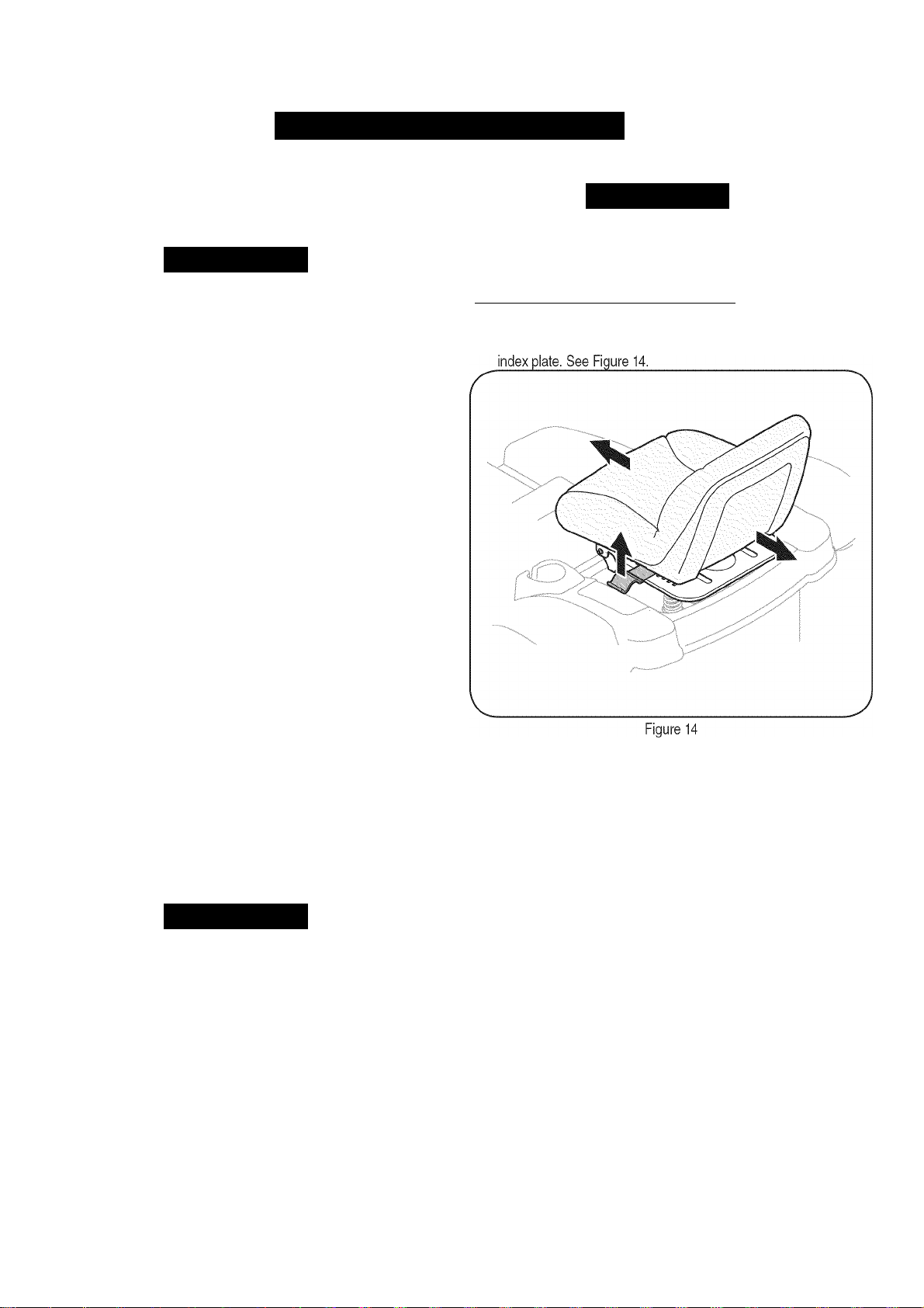
1. While sitting in the seat, grasp the seat adjustment lever on the
left side of the seat and pull it upward to disengage from the seat
CHECKING MAIN HARNESS FUSE
• A 20 amp fuse is installed in your tractor’s wiring harness to
protect the tractor’s electrical system from damage caused by
excessive amperage.
• If the electrical system does not function, or your tractor’s engine
will not crank, first check to be certain that the fuse has not blown.
• The fuse can be found inside of the dash panel behind the battery
tray. You may need to remove the battery to gain access to the
fuse. Always use a fuse with the same amperage capacity for
replacement.
NOTE: A second fuse holder can be found inside the dash panel. This
fuse holder is used for the optional 12 volt power outlet.
ADJUSTMENTS
AWARNING
Never attempt to make any adjustments while the engine is running,
except where specified in the operator’s manual. Disconnect spark
plug wire(s) before performing any adjustments, repairs or mainte
nance.
Steering and Transmission Linkage
The steering tie rod and drag links and the related transmission linkage
are set at the factory and should not require further adjustment.
Because of the complex adjustment procedure, the steering and
transmission linkage should only be serviced or adjusted by a qualified
mechanic. If you experience problems with steering, or with the IVT
transmission, contact your nearest Sears Parts & Repair Service
Center to have the tractor inspected.
2. Slide the seat to the desired position. See Figure 14.
3. Once the desired position is reached, release the seat lever. Slide
the seat slightly back and forth as necessary to engage the seat
lever into one of the eight adjustment positions in the index plate.
Make certain the seat is locked in position.
Side to Side Leveling the Deck
NOTE: Check the tractor’s tire pressure before performing any deck
leveling adjustments. Refer to “Tires” earlier in this section for informa
tion regarding tire pressure.
If the cutting deck appears to be mowing unevenly, a side to side
adjustment can be performed. Adjust it necessary as follows:
1. With the tractor parked on a firm, level surface, move the deck to
the mid height position (third or fourth notch) using the deck lift
lever. Rotate the left blade so that it is perpendicular to the tractor
frame. Measure and record the distance from the outside of the
left blade tip to the ground.
2. Moving to the other side of the tractor, rotate the right blade so
that it is perpendicular to the tractor frame, and measure the
distance from its outer blade tip to the ground.
3. Both measurements taken should be approximately equal. If
they’re not, note whether the left side of the deck is lower or
higher and proceed to the next step.
23
Page 24
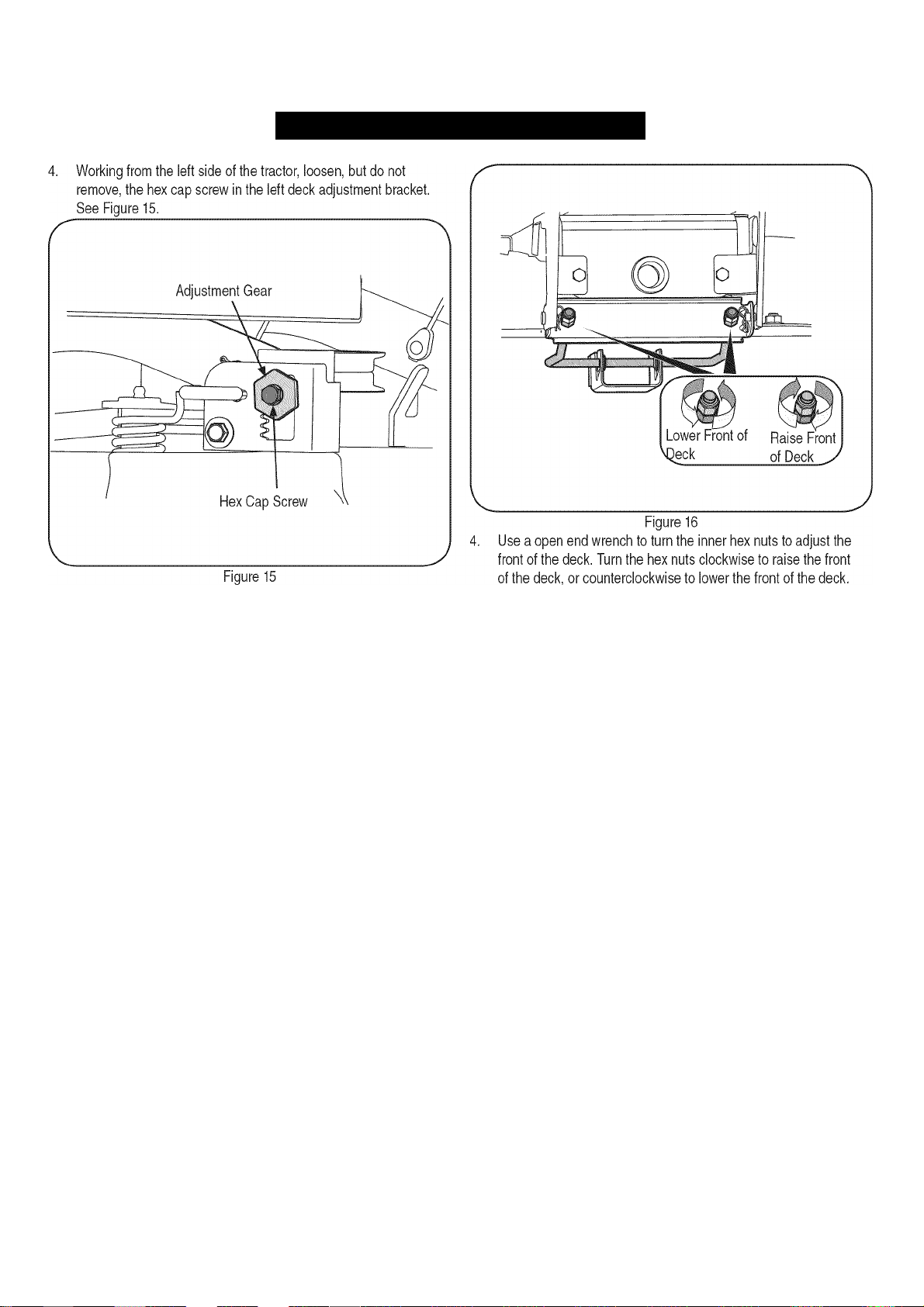
SERVICE AND MAINTENANCE
5. To even the deck turn the adjustment gear, located immediately
behind the hex cap screw, clockwise (rearward) to lower the left
side of the deck. Turn the gear counter-clockwise (toward front) to
raise the left side of the deck. See Figure 15.
6. The deck is properly leveled when both blade tip measurements,
as described earlier, are equal.
7. Retighten the hex cap screw in the left deck adjustment bracket
when proper adjustment is achieved.
Front To Rear Deck Leveling
The front of the cutting deck is supported by an adjustable front deck
hanger rod. This rod can be adjusted to set the front to rear pitch of
the deck. The front of the deck should be approximately 1/4-inch lower
than the rear of the deck.
Adjust it necessary as follows:
NOTE: The deck should first be leveled side to side. Check the side to
side level of the deck and adjust it necessary.
1. With the tractor parked on a firm, level surface, move the deck to
the mid height position (third or fourth notch) using the deck lift
lever. Carefully rotate the RH blade (nearest the discharge chute)
so that it is parallel with the tractor frame.
2. Measure the distance from the front of the blade tip to the ground
and the rear of the blade tip to the ground. The front measure
ment taken should be approximately 1/4” less than the rear
measurement. Determine whether the front of the deck has to be
raised or lowered.
3. Working at the front of the tractor, loosen the two hex lock nuts at
the front of the deck hanger rod. Thread the lock nuts away from
the hex nuts behind them. Refer to Figure 16.
Adjust the hex nuts evenly so that the deck hanger rod is at the
front of both slots in the hanger bracket on the front of the deck.
See Figure 16.
Retighten the two hex lock nuts when properly adjusted.
Deck Gauge Wheel
NOTE: The deck gauge wheels are an anti-scalp feature of the deck
and are not designed to support the weight of the cutting deck.
The deck gauge wheels should neither contact the ground, nor be high
off the ground, when the deck is moved to the desired height setting. If
you change your cutting height during the mowing season, the gauge
wheels should be checked and adjusted as necessary.
Adjust the gauge wheels as follows:
1. Place the tractor on a flat surface and move the deck to the
desired mowing height using the deck lift lever.
2. Check gauge wheels distance from the flat surface below. If the
gauge wheels contact the ground, they must be raised. If the
gauge wheels are higher than 1/2” above the ground, they should
be lowered.
3. Remove the hex flange lock nut and shoulder bolt securing one of
the front gauge wheels to the front index bracket. Reposition the
gauge wheel to align with the one of five index holes that places
the wheel 1/4” to 1/2” above the ground. Secure the gauge wheel
to the index bracket with the shoulder bolt and flange lock nut.
Note the index hole used and secure the other gauge
wheel in the same position. See Figure 17.
24
Page 25
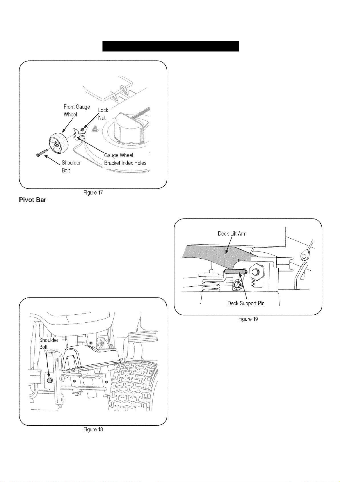
SERVICE AND MAINTENANCE
If excessive play is experienced in the steering wheel, check the pivot
bar for forward/rearward movement.
1.
Raise the front of the tractor and set it on jack stands, so the front
wheels are suspended above the ground.
2.
Grasping the ends of the pivot bar, attempt to move each end
of the axle forward and rearward to check for side play. There
should be minimal or no side play.
3.
If there is no side play, lower the tractor to the ground and have
the steering linkage inspected by your Sears Parts & Service
Repair Center. If there is side play, tighten the pivot bar as follows:
a. Support the pivot bar, then remove the hex lock nuts secur
ing the two shoulder bolts that pass through the pivot bar
bracket, the pivot bar, and frame. Refer to Figure 18.
b. Slide a half inch flat washer, with a maximum thickness of
.030 inch, onto each shoulder bolt. Reinstall the shoulder
bolts w/washers and fasten with the two hex lock nuts.
c. Gradually and evenly tighten the hex lock nut while continu
ing to check the forward/rearward movement of the pivot bar.
Tighten the lock nuts until minimum play, without binding the
pivot bar's up and down movement, is achieved.
CUTTING DECK REMOVAL
To remove the cutting deck, proceed as follows:
1.
Disengage the PTO (Blade Engage) and engage the parking
brake.
Place the deck gauge wheels in their highest setting (lowest deck
setting).
Lower the deck by moving the deck lift lever into the bottom notch
on the right fender.
4.
Looking at the cutting deck from the left side of the tractor, locate
the deck support pin on the rear left side of the deck. Refer to
Figure 19.
Pull the deck support pin outward to release the deck from the
deck lift arm. Pivot the support pin handle downward to lock the
pin in the disengaged position. Refer to Figure 19.
25
Move to the right side of the tractor and repeat the previous step
to release the deck from the RH lift arm.
Move the deck lift lever into the top notch on the right fender to
raise deck lift arms up and out of the way.
Carefully slide the cutting deck forward until the front deck hanger
rod can be removed from the slots of the hanger bracket at the
front of the deck.
9.
The PTO belt is captured inside the PTO pulley on the bottom of
the engine by a belt keeper. From beneath the front/left side of
the tractor, locate the hex tapping screw securing the left side of
the belt keeper to the bottom of the tractor frame.
10.
After noting the frame hole into which right side of the belt keeper
is inserted, remove the hex tapping screw and belt keeper. Slide
the PTO belt off the tractor’s PTO pulley.
11.
While holding the front deck hanger rod upward to clear the deck
front hanger bracket, carefully slide the deck out from the right
side of the tractor.
Page 26
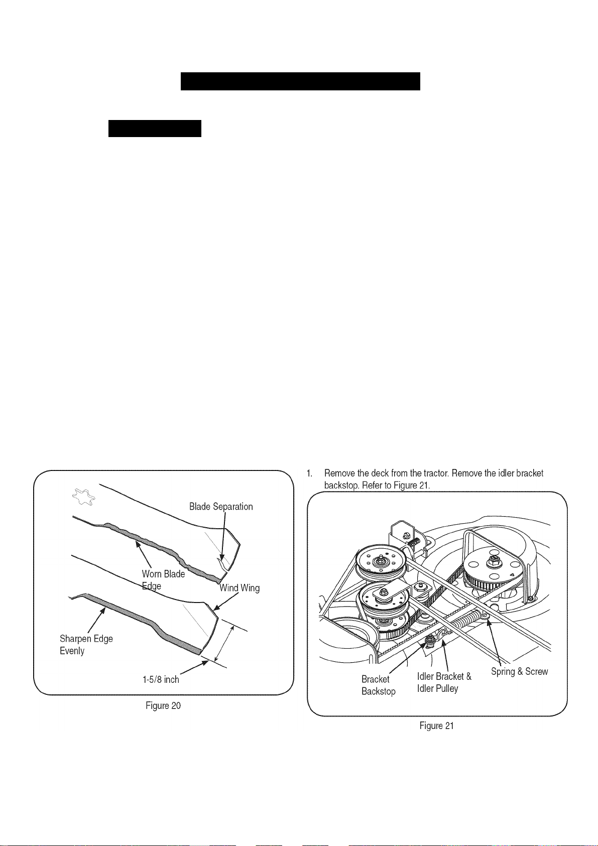
SERVICE AND MAINTENANCE
J
BLADES
Awarning
Be sure to shut the engine off, remove ignition key, disconnect the
spark plug wire(s) to prevent unintended starting before removing the
cutting blade(s) for sharpening or replacement. Protect your hands
by using heavy gloves or a rag to grasp the cutting blade.
The blades may be removed as follows:
1. Remove the deck from beneath the tractor, (refer to Cutting Deck
Removal) then gently flip the deck over to expose its underside.
NOTE: Place a block of wood between the deck housing and the
cutting edge of the blade to help in breaking loose the hex nut securing
the blade.
2. Use a 15/16” wrench to loosen the hex flange nut securing the
blade to the bottom of the spindle assembly. Secure the spindle
by either holding the blade tightly, or by using a second wrench to
hold the nut at the top of the spindle.
3. Continue holding the blade onto the star hub of the spindle, and
remove the flange nut and cutting blade.
4. Repeat the previous steps to remove the other blade.
5. To properly sharpen the cutting blades, remove equal amounts
of metal from both ends of the blades along the cutting edges,
parallel to the trailing edge, at a 25° to 30° angle.
IMPORTANT: If the cutting edge of the blade has already been
sharpened to within 1-5/8” width from the opposite edge, or if any
metal separation is present, replace the blades with new ones. See
Figure 20.
6. It is important that each cutting blade edge be ground equally to
maintain proper blade balance.
7. A poorly balanced blade will cause excessive vibration and may
cause damage to the tractor and result in personal injury. The
blade can be tested by balancing it on a round shaft screwdriver.
Grind metal from the heavy side until it balances evenly.
IMPORTANT: When replacing the blades, make certain the side of the
blade marked “Bottom” faces the ground when the mower is turned to
the operating position.
IMPORTANT: Note that the stars of the blades (and spindles) are not
symmetrical. The blade can be installed on each spindle in only one
direction. Carefully align the star hole of the blade with the star of the
spindle shaft when installing each blade. DO NOT improperly align the
blade and spindle shaft, and attempt to seat the blade onto the spindle
by tightening the hex flange nut.
8. Rotate the blade as necessary to align its star hole with the star
of the spindle shaft, then slide the blade onto the spindle shaft.
Thread the hex flange onto the spindle shaft and use a torque
wrench to tighten the hex flange nut to 70 to 90 foot-pounds.
9. Repeat the above procedure to install the other blade.
Checking Blade Timing
During normal operation the timing of the cutting blades can be altered
by abnormal loads on one, or both, cutting blades. Regularly check the
timing arrows on the spindle assemblies to make certain they are 90°
from each other.
If the timing arrows are not 90° from each other, proceed as follows:
26
Page 27
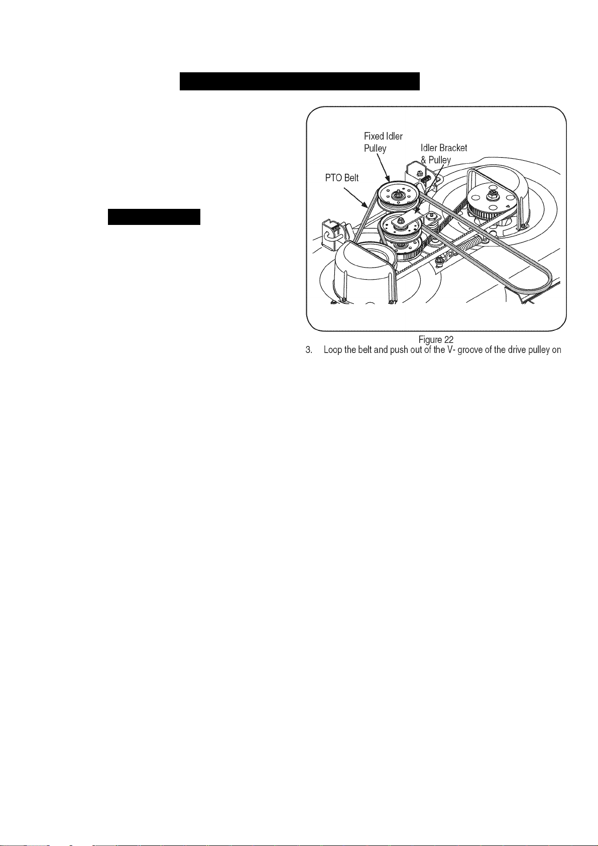
SERVICE AND MAINTENANCE
Pivot the idler bracket/idier pulley to relieve the tension on the
timing belt, and reposition the drive pulley and/or timing pulley to
achieve the 90° orientation of the timing arrows on the pulleys.
Re-install the idler bracket backstop and position so that there is a
1/8” gap between the backstop and idler bracket. Tighten the hex
screw and flange lock nut to secure in the adjusted position.
BELTS
Awarning
Be sure to shut the engine off, remove ignition key, disconnect the
spark plug wire(s) to prevent unintended starting before removing the
belt(s).
PTO Belt
All belts on your tractor are subject to wear and should be replaced it
any signs of wear are present.
IMPORTANT: Do not use substitute belts. The belt found on your
tractor is specially designed tor optimal performance and service life
for your deck application. Use only OEM original replacement belts.
To replace the PTO belt, proceed as follows:
1. Remove the deck from beneath the tractor (refer to Cutting Deck
Removal).
2. Maneuver the PTO belt downward and off the idler pulley on the
spring loaded idler bracket.
NOTE: It may be necessary to loosen the hex cap screw and flange
lock nut securing the pulley to the idler bracket to fit the belt between
the pulley and bracket. Slide the belt between the bottom of the idler
pulley and top of the timing belt idler pulley below. See Figure 22.
the right hand spindle assembly. Lift the belt over the pulley and
out from beneath the spindle cover. See Figure 22.
4.
Loop the new PTO belt and slide between the top of the drive
pulley and spindle cover. Maneuver the belt around and into the
V-groove of the drive pulley.
5. Route the back side of the belt around idler pulley and between
the idler pulley and idler bracket. Re-tighten the hex screw and
flange lock nut it loosened earlier. Refer to Figure 22.
6. Route the belt around the fixed idler pulley as shown in Figure 22
and re-install the deck as described in “Reinstalling the Cutting
Deck” later in this section.
Timing Belt
To replace the timing belt, proceed as follows:
1. Remove the deck from beneath the tractor (refer to Cutting Deck
Removal).
2. Remove the PTO belt drive pulley of the right hand spindle
assembly as described in “PTO Belt.”
3. Remove the hex screw, flat washer, lock washer, shoulder spacer,
and flange lock nut that make up the idler bracket backstop. Refer
to Figure 21 above.
NOTE: It may be necessary to clean the underside of the mowing deck
to access the hex screw.
Page 28
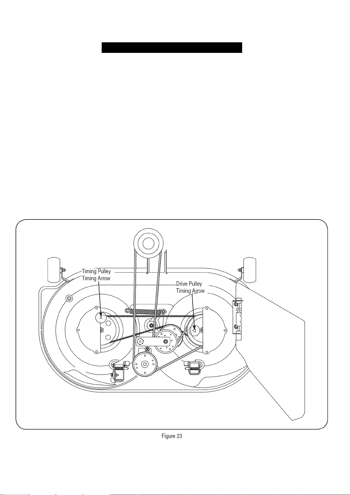
SERVICE AND MAINTENANCE
Applying force to either the timing belt idler pulley or the timing 9.
belt idler bracket, pivot and hold the idler bracket against the
spring tension just tar enough to allow lifting the timing belt off
and above the idler pulley. Carefully release the idler bracket. See
Figure 21. 10.
Loop the timing belt and lift out of the timing pulley and over the
right hand spindle assembly. Maneuver the belt between the drive 11,
pulley on top of the spindle assembly and the spindle cover to
remove. -|2_
Repeat the above procedure to remove the belt from the left hand
spindle assembly timing pulley. Refer to Figure 21.
Loop the new timing belt and maneuver the belt between the drive
pulley on top of the right hand spindle assembly and the spindle 13,
cover. Lower the belt until loosely around the right hand timing
pulley. Refer to Figure 21.
Note the arrows on the top of the timing pulley on the LH spindle
and on the drive pulley of the RH spindle assembly. These timing
arrows MUST be positioned 90° from each other as shown in
Figure 23.
14,
Rotate the RH spindle assembly to position the drive pulley timing
arrow as shown in Figure 19. Then without moving the RH drive
pulley, pull the timing belt tight against the RH timing pulley, above
the timing belt idler pulley, and over to the LH timing pulley.
Turn the LH timing pulley so that its timing arrow is 90° from the
RH spindle assembly timing arrow. Refer to Figure 23.
While making sure not to change the position of either pulley, loop
the timing belt over the LH timing pulley.
After making sure the spring is hooked onto the idler bracket and
screw, pivot the timing idler bracket/idler pulley against the spring
tension just far enough to allow you to lower the backside of the
timing belt onto the idler pulley. See Figure 23.
Re-check the timing arrows on the two pulleys. If they have
moved from the 90° position when tensioning the timing belt, pivot
the idler pulley to relieve tension on the belt and re-position the
pulleys. The timing arrows MUST be positioned 90° from each
other as shown in Figure 23.
Re-install the idler bracket backstop components as originally
installed in the deck housing, and position so that there is a 1/8”
gap between the backstop and idler bracket. Tighten the hex
screw and flange lock nut to secure in the adjusted position.
28
Page 29
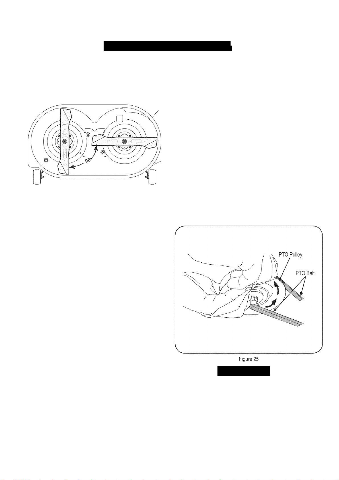
SERVICE AND MAINTENANC
I
J
15. If the timing belt was installed correctly and the timing arrows
were positioned as shown in Figure 23, the cutting blades should
be in the position shown in Figure 24.
V.
Figure 24
16. Reinstall the PTO belt onto the RFI spindle drive pulley and
re-install the deck as described in “Re-installing the Cutting Deck”
below.
3. Using the deck lift lever, lower the deck lift arms. From either side
of the tractor, pull the support pin in the deck rear hanger bracket
outward, align the deck lift arm hole with the deck support pin and
release the pin so that it goes through the deck lift arm. Repeat on
the other side of the tractor to secure the deck.
4. After first making sure the deck belt is properly engaged in all of
the deck pulleys, route the deck belt forward through the center
of the front deck hanger rod and toward the PTO pulley on the
bottom of the engine.
5. Using the deck lift handle, raise the deck to the position that gives
you the most horizontal run of the belt between the deck pulleys
and the PTO pulley on the bottom of the engine.
6. Sitting in front of the tractor, facing rearward, make certain the
belt is not twisted; then reach beneath the tractor to grasp the belt
and pull it toward the PTO pulley.
NOTE: References to left and right are from the front of the tractor in
the following instructions.
7. Pull the right side of the belt forward and place the narrow V side
of the belt into the PTO pulley.
8. While holding the belt and pulley together, rotate the pulley to the
left. Continue holding and rotating the pulley and belt until the belt
is fully rolled into the PTO pulley. See Figure 25.
Transmission Drive Belt
NOTE: Several components must be removed, including transmission
steering linkage which will have to be readjusted, in order to change
the tractor's transmission drive belt. Contact your Sears Parts &
Service Repair Center to have your transmission drive belt replaced.
REINSTALLING THE CUTTING DECK
There are two methods for reinstalling the mower deck on the tractor.
One method involves rotating the PTO belt idler bracket to relieve
enough belt tension to allow the belt to be placed in either the PTO
pulley or the fixed idler pulley. Because that method is difficult, we
recommend using the second method of rolling the belt onto the PTO
pulley.
Install the cutting deck as follows:
1. From the right side of the tractor, slide the deck under the tractor
and align the rear deck hanger brackets with the deck lift arms.
2. Slide the deck forward and place the deck front hanger rod into
the slots of the deck front hanger bracket. Then slide the deck
rearward so that the front hanger rod is at the front of the slots.
AWARNING
Use caution to prevent pinching your fingers when rolling the belt
onto the PTO pulley.
29
Page 30

OFF-SEASON STORAG
Awarning
Never store lawn tractor with fuel in tank indoors or in poorly
ventilated areas where fuel fumes may reach an open flame, spark,
or pilot light as on a furnace, water heater, clothes dryer, or gas
appliance.
I
PREPARING THE ENGINE
IMPORTANT: Fuel left in the fuel tank during warm weather deterio
rates and will cause serious starting problems.
To prevent gum deposits from forming inside the engine’s carburetor
and causing possible malfunction of the engine, the fuel system must
be either completely emptied, or the gasoline must be treated with a
stabilizer to prevent deterioration.
1. If using a fuel stabilizer:
• Read the product manufacturer’s instructions and recommenda
tions.
• Add to clean, fresh gasoline the correct amount of stabilizer for
the capacity of the fuel system.
• Fill the fuel tank with treated fuel and run the engine for 2-3
minutes to get stabilized fuel into the carburetor.
2. If emptying the fuel system:
• Do not drain fuel when the engine is hot. Allow the engine
adequate time to cool. Drain fuel into an approved container
outdoors, away from open flame.
• Drain any large volume of fuel from the tank by disconnecting the
fuel line from the in-line fuel filter near the engine.
Awarning
Gasoline is extremely flammable and can be explosive under certain
conditions. Drain gasoline before storing the equipment for extended
periods. Drain fuel only into an approved container outdoors, away
from an open flame. Allow engine to cool. Extinguish cigarettes,
cigars, pipes, and other sources of ignition prior to draining fuel.
Store gasoline in an approved container in safe location.
Awarning
Gasoline is a toxic substance. Dispose of gasoline properly. Contact
your local authorities for approved disposal methods.
3. Remove the spark plug and pour one (1) ounce of engine oil
through the spark plug hole into the cylinder. Crank the engine
several times to distribute the oil. Replace the spark plug.
PREPARING THE LAWN TRACTOR
• Clean and lubricate tractor thoroughly as described in the lubrica
tion instructions.
• Do not use a pressure washer or garden hose to clean your unit.
• Store mower in a dry, clean area. Do not store next to corrosive
materials, such as fertilizer.
Reconnect the fuel line and run the engine until it starts to falter,
then use the choke to keep the engine running until all fuel in the
carburetor has been exhausted.
Again disconnect the fuel line and drain any remaining gasoline
from the system.
30
Page 31

1
I
TROUBLESHOOTIN
J
Problem
Engine fails to start 1. PTO/Blade Engage knob engaged.
2. Parking brake not engaged.
3. Spark plug wlre(s) disconnected.
4. Throttle control lever not In correct starting
position.
5. Choke not activated
6. Fuel tank empty, or stale fuel.
7. Blocked fuel line.
8. Faulty spark plug(s).
9. Engine flooded.
Engine runs erratically 1. Unit running with CHOKE activated.
2. Spark plug wlre(s) loose.
3. Blocked fuel line or stale fuel.
4. Vent In gas cap plugged.
5. Water or dirt In fuel system.
6. Dirty air cleaner.
Engine overheats 1. Engine oil level low.
2. Air flow restricted.
Engine hesitates at high RPM 1. Spark plug gap too close. 1. Remove spark plug and reset the gap.
Engine idles rough 1. Spark plug fouled, faulty or gap too wide.
2. Dirty air cleaner.
Excessive vibration 1. Cutting blade loose or unbalanced.
2. Damaged or bent cutting blade.
Mower will not mulch grass 1. Engine speed too low.
2. Wet grass.
3. Excessively high grass.
4. Dull blade.
Uneven cut 1. Deck not leveled properly.
2. Dull blade.
3. Uneven tire pressure.
Cause Remedy
1. Place knob In disengaged (OFF) position.
2. Engage parking brake.
3. Connect wire(s) to spark plug(s).
4. Place throttle lever to FAST position.
5. Pull the CHOKE control outward.
6. Fill tank with clean, fresh (less than 30 days old) gas.
7. Clean fuel line and replace fuel filter.
8. Clean, adjust gap or replace plug(s).
9. Crank engine with throttle In FAST position.
1. Push CHOKE control in.
2. Connect spark plug wire(s).
3. Clean fuel line; fill tank with clean, fresh gasoline and
replace fuel filter.
4. Clear vent or replace cap If damaged.
5. Drain fuel tank. Refill with clean, fresh gasoline.
6. Replace air cleaner paper element or clean foam
pre-cleaner.
1. Fill crankcase with proper amount and weight of oil.
2. Clean grass clippings and debris from around the
engine's cooling fins and housing.
1. Replace spark plug. Set plug gap.
2. Replace air cleaner element and/or clean pre
cleaner.
1. Tighten blade and spindle.
2. Replace blade.
1. Place throttle In FAST (rabbit) position.
2. Do not mulch when grass Is wet.
3. Mow once at a high cutting height, then mow again
at desired height or make a narrower cutting swath.
4. Sharpen or replace blade.
1. Perform side-to-side deck adjustment.
2. Sharpen or replace blade.
3. Check tire pressure in all four tires.
NEED MORE HELP?
iswer and more on managemyhome.cotn - for free!
® Find this and all your other product manuals online.
® Get answers from our team of home experts.
” Get a personalized maintenance plan for your home.
” Find information and tools to help with home projects.
inanaaf* honrif»
31
Page 32

Craftsman Revolution Model 247.28933
PARTS LIS
I
28
32
23,
‘
...
17--,-
7
( 'V
1^.
2-^
- -12
-
^^3
Page 33

Craftsman Revolution Model 247.28933
Ref. No. Part No. Description
1. 683-04269-0637 Frame Assembly
2. 710-04377 Screw, Hex Cap Lock, 7/16-20 x 2.75
3. 710-04484 Screw, Hex Wash., 5/16-18 x .75
4. 710-04666 Screw, Hex Flange Hd., 1/4-20 x .75
5. 710-0599 Screw, Hex Wash., 1/4-20 x .5
6. 710-0642 Screw, Hex Wash., 1/4-20 x .75
7. 710-3005 Screw, Hex Cap, 3/8-16 x 1.25 Gr5
8. 712-0271 Nut, Hex Sems, 1/4-20
9. 712-04064 Nut, Hex Flange Insert Lock, 1/4-20
10. 712-04065 Nut, Hex Flange Insert Lock, 3/8-16
11. 712-3087 Nut, Wing, 1/4-20
12. 917-04526 Clutch, Electric PTO
13. 725-0157 Cable Tie
14. 725-04439 Solenoid, Start
15. 925-1707D Battery
16. 731-05659 Bushing, Steering Shaft
17. 936-0171 Washer, Lock, 7/16
18. 738-04058 Spacer, Shoulder, .38 x 1.0 x .7
19. 738-1132 Screw, Shoulder, .25 x .15:1/4-20
20. 747-04215-0637 Strap, Battery
21. 750-04763 Spacer, 1.37 x I.OOx .25
22. 756-04354 Pulley, Engine
23. 747-05056 Rod, Belt Keeper
24. 783-04806-0637 Bracket, Pivot Bar
25. 783-04844-0637 Bracket, Pivot Support RH
26. 783-04845-0637 Bracket, Pivot Support LH
27. 783-04868-0637 Bracket, Steering Support
28. 783-0491OA-0637 Bracket, Support Fender
29. 783-05469-0637 Bracket, Battery Support
30. 783-05617B-0637 Bracket, Running Board Support - LH
783-06193-0637 Bracket, Running Board Support - RH
31. 783-05760-0637 Bracket, Pivot Bar Support
32. 783-05850-0637 Plate, Seat Frame
33. 710-04484 Screw, Hex Wash., 5/16-18 x .75
I
PARTS LIS
J
33
Page 34

Craftsman Revolution Model 247.28933
PARTS LIS
I
34
39-
Page 35

Craftsman Revolution Model 247.28933
I
PARTS LIS
J
Ref. No. Part No. Description
1. 710-0192 Screw, Truss Hd. Mach., 10-24 x .375
2. 710-0599 Screw, Hex Wash, 1/4-20 x .5
3. 710-0604A Screw, Hex Wash, 5/16-18 x .625
4. 710-04484 Screw, Hex Wash, 5/16-18 x .75
5. 710-0642 Screw, Hex Wash, 1/4-20 x .75
6. 710-0895 Screw, Hex Wash, 1/4-15 x .75
7. 710-3217 Screw, Truss Hd. Mach., #8-32 x .375
8. 712-0142 Nut, Hex, 8-32
9. 725-0157 Tie, Cable
10. 925-04022B Meter, Indicator/Service Monitor
11. 925-04174 Switch, PTO
12. 925-04227B Switch, Ingition/Module
13. 925-1745A Key, Ignition, w/ Plastic Cover
925-1744A Key, Ignition, w/o Plastic Cover
14. 720-3025 Plug
15. 925-0963 Bulb, 12V Light
16. 925-1649 Receptacle, Light
17. 726-3046 Clip, Ratchet
18. 731-04213 Lever, Dash Brake
19. 731-05406 Panel, Dash
20. 731-06830 Hood
21. 731-05935 Plenum, Hood
22. 731-05525 Lens, Head Light LH
23. 731-05526 Lens, Head Light RH
24. 731-1857 Knob, Throttle Control
Ref. No. Part No. Description
25. 935-0149 Bushing, Fuel Tank
26. 735-0271A Bumper
27. 735-04076 Net, Storage
28. 936-0463 Washer, Flat, .25 x .63 x .0515
29. 738-04091A Screw, Shoulder, .43 x .29:TT5/16-18
30. 746-04132 Cable, Choke Control
31. 746-1100 Cable, Throttle Control
32. 747-1155 Rod, Brake Lock Pivot
33. 751-10442 Fitting, Fuel Pick Up
34. 751-10692 Tank, Fuel
35. 751-10703 Cap, Fuel Tank
36. 783-04285F-0637 Support, Dash, R.H.
37. 783-04323F-0637 Support, Dash, L.H.
38. 683-04536 Bracket, Hood Pivot
39. 783-04840-0637 Bracket, Hood Pivot RH
40. 783-04841-0637 Bracket, Hood Pivot LH
41. 783-05162-0637 Bracket, Hood Support
42. 777X42426 Label, Reflector
43. 777X42427 Label, Reflector
44. 783-05140-0637 Brkt., Strg. Support, RH
45. 783-04798-0637 Brkt., Strg. Support, LH
46. 783-04799-0637 Brkt., Support, Upper Strg.
47. 725-2003 12V Power Receptacle
—
925-04375A Harness, Main Wire
— 937-04050 Grease Gun Kit
35
Page 36

Craftsman Revolution Model 247.28933
PARTS LIS
I
36
Page 37

Craftsman Revolution Model 247.28933
I
PARTS LIS
J
Ref. No. Part No. Description
1. 647-04095A-0637 Shaft, Lift
2. 710-04187 Screw, Hex Wash Hd. H/L, 1/4-15 x .5
3. 710-04484 Screw, Hd. Tapp, 5/16-18 x .75
4. 710-0451 Screw, Carriage, 5/16-18 x 75
5. 710-0599 Screw, Hd. Tapp, 1/4-20 x .5
6. 710-1260A Screw, Hd. Tapp, 5/16-18 x .75
7. 710-0895 Screw, Hd. Tapp, 1/4-15 x .75
8. 712-04063 Nut, Hex Flange Insert Lock, 5/16-18
9. 712-04065 Nut, Hex Flange Insert Lock, 3/8-16
10. 914-0104 Pin, Internal Cotter
11. 914-0111 Pin, Cotter, 3/32 X 1.0
12. 716-0106A E-ring, .625 Shaft
13. 720-0311 Grip, Handle
14. 726-0135 Nut, Speed, .3125 Dia.
15. 726-0221 Nut, Speed, .5
16. 726-3046 Clip, Ratchet
17. 731-06836 Cover, Rear Fender RH
18. 731-06835 Cover, Rear Fender LH
19. 731-06208 Spacer, Seat Adjust
20. 732-04459 Spring, Lift Handle Torsion
21. 732-04491 Spring, Seat Adjust
22. 732-04508 Spring, Compress., 1.71 x 3.25 x .23
23. 732-0826A Spring, Extension, .865 x 4.68
24. 735-04078A Pad, Foot RH
Ref. No. Part No. Description
25. 735-04109 Pad, Foot LH
26. 936-0192 Washer, Flat, .535 x .93 x .09
27. 736-3078 Washer, Flat, .344 x 1.0 x .063 HT
28. 738-0138A Bolt, Shoulder, .496x2.5:3/8-16
29. 938-0373 Bolt, Shoulder, .496 x 1.525:3/8-16
30. 738-04130 Bolt, Shoulder, .625 x .175:3/8-16
31. 941-0225 Bearing, Hex Flange,
32. 946-04546 Cable, Lift, 16.64 Lg
33. 946-04436 Cable, Lift, 16.64 Lg
34. 747-04701 Handle, Lift
35. 747-04821 Rod, Seat, 5/16 x 11.62
36. 750-04945 Spacer, .51 x .75 x 1.0
37. 756-04331 Pulley, Roller
38. 757-04104 Seat, High Back
39. 783-04977A-0637 Plate, Deck Lift Index
40. 783-04494B-0637 Arm, Deck Lift RH
41. 783-0471 IB-0637 Arm, Deck Lift LH
42. 783-05816-0637 Bracket, Seat Pivot
43. 783-05817-0637 Plate, Seat Mounting
44. 783-05865A-0637 Fender, Rear
45. 925-04040 Switch, Seat
46. 725-04658 Harness, Seat Switch Jumper
47. 757-04040 Arm Rest, Seat
37
Page 38

Craftsman Revolution Model 247.28933
PARTS LIS
I
Page 39

Craftsman Revolution Model 247.28933
I
PARTS LIS
J
Ref. No. Part No. Description
1. 918-04414 Steering Assembly, Synchro
2. 631-04331 Wheel Assembly, Steering
3. 634-04415 Wheel Assembly, 15 x5 x6
734-04347-0901 Tire, 15 x5 x6
634-04104 Rim Assembly
737-0224 Grease Fitting
941-04137 Bearing
934-0255 Valve, Tubeless Air
4. 683-04439 Axle Assembly, RH
5. 683-04440 Axle Assembly, LH
6. 647-04080A-0637 Rod, Fender Support
7. 683-04285-0637 Link, Steering, IVT
8. 710-04006 Screw, Flex Wash, 5/16-18 x 2.0
9. 710-04187 Screw, Flex Wash, Hi/Lo, 1/4-15 x .5
10. 710-04389 Screw, Flex Wash, 5/16-18 x 2.25
11. 710-04484 Screw, Flex Wash, 5/16-18 x .75
12. 710-04692 Screw, Flex Cap, 3/8-16 x 7.25 Gr5
13. 710-0513 Screw, Flex Cap Lock, 1/4-28 x .625
14. 710-0520 Screw, Flex Cap, 3/8-16 x 1.5 Gr5
15. 710-0528 Screw, Flex Cap, 5/16-18 x 1.25 Gr5
16. 710-0597 Screw, Flex Cap, 1/4-20 x 1.00
17. 710-0599 Screw, Flex Wash, 1/4-20 x .5
18. 710-0642 Screw, Flex Wash, 1/4-20 x .75
19. 710-0650 Screw, Flex Wash, 5/16-18 x .875
20. 710-3015 Screw, Flex Cap, 1/4-20 x .75 Gr5
21. 710-3119 Screw, Flex Cap Lock, 3/8-16 x .75
22. 710-3144 Screw, Flex Cap, 3/8-16 x 2.0 Gr5
23. 710-3296 Screw, Flex Cap Lock, 1/4-20 x .75
24. 711-04472 Link, Drag
25. 711-04562 Shaft, Steering Pivot Gear
26. 711-04722 Pin, Clevis, .375 x .969 HT
27. 712-0312A Nut, Jam, 3/8-24 LFI Thrd
28. 741-04280 Brg., Ball
29. 712-0375 Nut, Flex Lock, 3/8-16
30. 712-04063 Nut, Flex Insert Flange Lock, 5/16-18
31. 712-04064 Nut, Flex Insert Flange Lock, 1/4-20
32. 712-04065 Nut, Flex Insert Flange Lock, 3/16-16
33. 912-3001 Nut, Flex Jam, 3/8-24 Gr2
34. 913-04037 Link, Connecting
35. 914-0104 Pin, Internal Cotter
36. 714-04039 Pin, Cotter, 5/32 x 1.25
Ref. No. Part No. Description
37. 717-04274A Gear, Spur, 12T
38. 717-04275A Gear, Spur, RFI13T
39. 717-04282A Gear, Spur, LFI 13T
40. 719-04170A Axle, Pivot Bar
41. 719-04287-0637 Arm, Steering, LFI
42. 719-04288-0637 Arm, Steering, RFI
43. 723-04035 End, Ball Joint Rod
44. 723-04036 End, Ball Joint Rod, LH Thrd.
45. 738-1011A Bolt, Shoulder, .5 x 2.23:3/8-16
46. 731-05476 Cover, Steering Gear, RH
47. 731-05618 Cover, Steering Gear, LH
48. 731-06825 Cap, Steering Wheel
49. 936-0185 Washer, Flat, .375 x .738.063
50. 736-0270 Washer, Bell, .265 x .75 x .062
51. 936-0300 Washer, Flat, .406 x .875 x .059
52. 736-0315 Washer, Flat, .76 x 1.5 x .12
53. 936-0452 Washer, Bell, .396 x 1.14 x .095
54. 736-0866 Washer, Flat, .755 x 1.92 x .060
55. 936-3004 Washer, Flat, .406 x .875 x .105
56. 736-3052 Washer, Flat, .406 x 1.0 x .105
57. 931-3020 Hub Cap
58. 937-3000 Fitting, Grease
59. 738-04189 Shaft, Steering, .625 x 17.281
60. 738-04240 Nut, Shoulder, .375 x .5
61. 747-04496 Rod, 3/8-24 X 14.4 Lg
62. 748-04139 Block, Steering Shaft
63. 750-04676 Spacer, .385 x .63 x .75
64. 750-04776 Spacer, .380 x .625 x .265
65. 736-04299 Washer, Flat, .281 x .50 x .04
66. 750-04855 Spacer, .385 x .75 x 3.47
67. 783-04798-0637 Bracket, Steering Support, LH
68. 783-04799-0637 Bracket, Steering Support, Upper
69. 783-05140-0637 Bracket, Steering Support, RH
70. 783-05184-0637 Plate, Base Cover, RH
71. 783-05185-0637 Plate, Base Cover, LH
72. 783-05956 Link, Cont., IVT
73. 783-05957 Bracket, IVT/Steering Adjustment
74. 783-05706 Bracket, Support Arm
75 710-04040 Scr, Shidr., .497 x .750
76 712-0376 Nut, 3/8-16
39
Page 40

Craftsman Revolution Model 247.28933
'27
PARTS LIS
I
'77
28
"28
40
Page 41

Craftsman Revolution Model 247.28933
I
PARTS LIS
J
Ref. No. Part No. Description
1. 783-04904-0637 Plate, Transmission
2. 918-04228 Hub, Wheel
3. 647-04174 Assembly, Control, Pedal, IVT
4. 647-04103B Assembly, Control, Brake, IVT
5. 683-04473-0637 Assembly, Hub, IVT Speed
6. 783-06385 Brkt., Brake, Neut., Brake Rod
7. 707-05194 Lever, Brake, Release, RH
8. 710-04484 Screw, Hex Wash, 5/16-12 x .75
9. 707-05196 Lever, Brake, Release, LH
10. 710-0627 Hhcs, 5/16-24 X .750
11. 710-0599 Screw, Hex Wash., 1/4-20 x .5
12. 710-0919 Screw, B, #10-16X. 440
13. 710-0641 Screw, Hex Cap, 1/4-20 x 2.25 Gr5
14. 710-1008 Screw, t t, 3/8-16 X 1.875
15. 710-1189 Screw, C, #12-24 x .625
16. 710-1208 Screw, tt, 5/16-18 X 3.50
17. 710-3005 Screw, Hex Cap, 3/8-16 x 1.25 Gr5
18. 710-0703 Screw, Crg, 1/4-20 x .75
19. 710-3144 Screw, Hex Cap, 3/8-16 x 2.0 Gr5
20. 710-1325 Screw, tt, 1/4-20 X 1.625
21. 911-0832 Ferrule, 3/8-24 x .375 Dia.
22. 710-3195 Hhcs, 5/16-18x4.50
23. 912-0298 Nut, Jam, 1/4-20
24. 712-3004A Nut, Hex Flange Lock, 5/16-18 Gr5
25. 712-0365 Nut, Hex Lock, M8 x 1.25
26. 712-3050 Nut, Lug, 7/16-14
27. 712-04063 Nut, Hex Flange Insert Lock, 5/16-18
28. 712-04065 Nut, Hex Flange Insert Lock, 3/8-16
29. 914-0104 Pin, Internal Cotter
30. 914-0111 Pin, Cotter, 3/32 X 1/0
31. 718-04597 Plate, Brake, Lever
32. 915-0143 Pin, Spirol, .25 X 1.25
33. 727-0626A Cyl, Damper
34. 731-05846 Fan, Hydro
35. 747-04935 Rod, Brake, IVT
36. 732-0335 Spring, Compression, .405 x 1.17
Ref. No. Part No. Description
37. 932-04262 Spring, Extension, .429 OD x 2.515
38. 732-0814 Spring, Extension, .56 x 5.52
39. 735-0239 Pad, Foot, 4.0 in. Lg
40. 735-04117 Pad, Reverse Pedal
41. 735-04175 Pad, Forward Pedal
42. 736-0242 Washer, Bell, .340 x .872 x .060
43. 938-0974 Scr, Shidr, .375 X.380 X 1/4-20
44. 736-3010 Washer, Flat, .407 x .812 x .135 HT
45. 750-05063 Spcr, Brake, IVT
46. 932-0429A Spring, Ext, .50 Dia. x 3.97 Lg.
47. 712-04064 Nut, FIgIk, 1/4-20
48. 736-3052 Washer, Flat, .406 x 1.00 x .105
49. 738-04356 Screw, Shoulder, .31 x .75 x 1/4-20
50. 938-0155 Bolt, Shoulder, .435 x .160 : 5/16-18
51. 938-0347 Spacer, Shoulder, .625 ID x .169
52. 738-04240 Nut, Shoulder, .375 Dia x .5
53. 941-0225 Bearing, Hex Flange
54. 741-3065B Bearing, Hex Flange, .625 ID Split
55. 747-04562A Rod, Park Brake
56. 747-04598A Rod, Drive Engage
57. 747-05088 Rod, Dump, IVT
58. 747-04951 Rod, Brake RH
59. 747-04932 Rod, Brake LH
60. 750-04686A Spacer, .325 x .500 x 2.480
61. 750-04456 Spacer, .26 X .372 x 1.42
62. 750-04776 Spacer, .38 x .625 x .265
63. 750-05026 Spacer, .375 x .5 x 2.0
64. 954-04139 V-Belt, 72.2
65. 756-04224 Pulley, Flat Idler, 2.75
66. 783-06140-0637 Brkt, Mt, Cyl
67. 756-04325 Pulley, V Type Idler, 3.06
68. 783-04570A-0637 Arm, Idler
69. 783-06373 Pedal, Fwd, IVT
70. 783-04981 Bracket, Park Brake
71. 783-05976-0637 Bracket, Support, IVT Pedal
72. 783-05290-0637 Belt Keeper, IVT
41
Page 42

Craftsman Revolution Model 247.28933
PARTS LIS
I
Ref. No. Part No. Description
73. 911-0677 Fri, 5/16-18 X.312 Dia.
74. 783-06377 Bracket, Pivot, iVT Rev
75. 783-06213 Pedal, Rev, IVT
76. 783-06224-0637 Bracket, Brace, Neutral Brake Rod
77. 631-04229 Reservoir Assembly
78. 725-04363 Switch, Interlock (Brake)
79. 725-04374 Harness, Reverse Jumper
80. 725-1644 Switch, Reverse
81. 926-0320 Plate, Insulator Nut
82. 738-04237A Screw, Shoulder, #10-32 : .5
83. 634-04239 Wheel Assembly, 20 x 8 x 8
734-1730 Tire, 20 X 8 X 8
934-0255 Valve, Tubeless Air
934-0246A-0729 Rim Assembly, Rear
84. 647-04168 Assembly, Pedal, Rev, IVT
85. 710-0227 Screw, Hd. Tapp., #8-18 x .5
Ref. No. Part No. Description
86. 710-0642 Screw., TT, 1/4-20 x .750
87. 714-04023 Pin, Cotter
88. 726-0214 Cap, Push
89. 736-0116 Washer, Flat, .635 x .93 x .06
90. 918-04344 RH Transaxle Assembly
91. 918-04345 LH Transaxle Assembly
92. 918-04406 IVT Transmission Assembly
93. 683-04369-0637 Transmission Support Bracket
94. 710-0642 Screw, TT, 1/4-20, 0.750, Hxindwsh
95. 710-1260A Screw, TT, 5/16-18, 0.750, Hxindwsh
96. 915-0221 Pin, 3/16x3/4
97. 726-0205 Hose Clamp, .490 Dia.
98. 936-0264 Flat Washer, .330 x .630 x .0635
99. 751-3130 Hose, 5/16IDX.56 0D
— 918-04850 IVT Transmission / Drive Assembly
(Incl. Refs. 77, 90-99)
93'
42
Page 43

Craftsman Revolution Model 247.28933
For Choke
-
I
PARTS LIS
J
Ref. No. Part No. Description
1. 683-04256-0637 Shield, Muffler
2. 710-0227 Screw, Hex Wash Hd. Tapp, #8-18 x .5
3. 710-04683 Screw, Hex Sems Tapp, 3/8-16 x 1.0
4. 710-0599 Screw, Hex Wash Hd. Tapp, 1/4-20 x .5
5. 710-0642 Screw, Hd. Tapp, 1/4-20 x .75
6. 710-3008 Screw, Hex Cap, 5/16-18 x .75 Gr5
7. 912-3005 Nut, Hex Flange Lock, 3/8-16 Gr5
8. 725-0157 Tie, Cable
9. 726-0205 Clamp, Hose
10. 728-04000 Rivet, Pop, .188 X .3
11. 936-0300 Washer, Flat, .406 x .875 x .059
12. 751-0564B Deflector, Muffler
Ref. No. Part No. Description
13. 751-10004 Pipe Exhaust, RH
14. 751-10161 Muffler, Dual Inlet
15. 751-10349-54 Hose, Fuel; Low Permeation, 51 inches
16. 751-10353 Deflector, Muffler
17 951-10517A Valve, Oil Drain
18. 751-3141-14 Hose, Oil Drain Extension
19. 783-04870-0637 Bracket, Muffler LH
20. 783-04872-0637 Bracket, Muffler RH
21. 721-0460 Gasket, Exhaust
22. 926-0154 Tie, Push Mount
23. 751-10005 Pipe, Exhaust, LH
24. 783-04783A Shid., Heat, Twin
43
Page 44

Craftsman Revolution Model 247.28933
PARTS LIS
I
Page 45

Craftsman Revolution Model 247.28933
I
PARTS LIS
J
Ref. No. Part No. Description
1. 918-04512A Spindie Assembiy - Drive
2. 918-04516 Spindie Assembiy - Driven
3. 638-04012A Boit Assembly, Shoulder
4. 983-04379A-0721 Deck Assembly
5. 683-04425-0721 Bracket, Idler
6. 710-0520 Screw, Hex Cap, 3/16-18 x 1.5 Gr5
7. 710-0528 Screw, Hex Cap, 5/16-18 x 1.25 Gr5
8. 710-0599 Screw, Hex Wash., 1/4-20 x .5
9. 710-04484 Screw, Hex Wash., 5/16-18 x .75
10. 710-1325 Screw, Hex Wash., 1/4-20 x 1.625
11. 710-3005 Screw, Hex Cap, 3/8-16 x 1.25 Gr5
12. 710-3144 Screw, Hex Cap, 3/8-16 x 2.0 Gr5
13. 710-3178 Screw, Carriage, 3/8-16 x .75
14. 912-0206 Nut, Hex, 1/2-13 Gr5
15. 712-0229 Nut, Push, 3/8
16. 712-0290 Nut, Hex Lock, 7/16-14
17. 712-04065 Nut, Hex Flange Insert Lock, 3/8-16
18. 712-0417A Nut, Hex Flange, 5/8-18
19. 912-0641 Nut, Hex, M16-1.5
20. 712-3083 Nut, Hex Insert Lock, 1/2013
21. 914-0470 Pin, Cotter, 1/8 X 1.25
22. 917-04074 Gear, Deck Adjust
23. 731-06291A Cover, Belt
24. 932-0306A Spring, Compression, .531 x 1.75
25. 732-04469 Spring, Torsion, 1.10 x 1.3
26. 732-0826A Spring, Extension, .865 x 4.68
27. 734-04155 Wheel, Deck Ball, 5.0
28. 936-0119 Washer, Lock, 5/16
29. 936-0176 Washer, Flat, .265 x .938 x .12
30. 736-0225 Washer, Internal Tooth Lock, 5/8
31. 736-0258 Washer, Flat, .385 x I.Ox .135
32. 936-0300 Washer, Flat, .406 x .875 x .059
33. 736-0322 Washer, Flat, .45 x 1.38 x .134
34. 936-3039 Washer, Flat, .406 x 2.5 x .164
35. 737-04003D Nozzle, Deck Wash
Ref. No. Part No. Description
36. 938-0785 Spacer, Shoulder, 1.38 x .445 x .36
37. 738-04162A Spacer, Shoulder, .884 x .190
38. 738-04316 Bolt, Shoulder, .435 x 1.76:5/16 -24
39. 938-3056 Bolt, Shoulder, .496x2.5:3/8-16
40. 942-04217 Blade, Timing 2 in 1, 22.0
41. 747-04530 Rod, Belt Keeper
42. 747-04863 Rod, Deck Front Hanger
43. 747-1116 Rod, Deck Release
44. 750-0566A Spacer, .26 x .372 x 1.03
45. 954-04167 Belt, Timing, .189T
46. 954-04185 V-Belt, Type A x 89.24
47. 756-04129 Pulley, Idler, 4.25 Dia
783-05627-0637 Bracket, Deck Hanger/Adjust LH
48.
49. 783-05802-0637 Bracket, Idler
911-0332 Pin, Clevis, .5 X .78
50.
914-04023 Pin, Internal Cotter
51.
783-0720C-0637 Bracket, Front Deck Rod
52.
53. 631-04254 Deflector Assembly, Chute
54. 711-04847A Pin, Hinge
55. 732-04372 Spring, Torsion, .44 x 2.0
56. 783-05823 Bracket, Chute Mounting
57. 619-04199 Housing, Spindle
58. 710-04065 Screw, Tri-Plask, 1/4-10 x .625
59. 913-04040A Pulley, Timing, 56T
60. 936-0287 Washer, Flat, .793 x 1.24 x .06 HT
61. 937-3000 Fitting, Lube
62. 941-0919 Bearing, Ball
63. 750-04936 Spacer, .792 x 1.06 x 1.86
64. 787-01520 Plate, Timing Pulley
65. 938-04292 Shaft, Spindle, 5.46 Long
66. 938-04291 Shaft, Spindle, 4.44 Long
67. 750-04724 Spacer, .735 x 1.375 x1.066
68. 756-04372 Pulley, Deck, Timing, 6.67 Dia
69. 736-0315 Washer, Flat, .76 x 1.5 x .12
70. 756-04280 Pulley, Idler, 3.50 Dia.
45
Page 46

PARTS LIST
Craftsman Engine Model 407777-0717-B1 For Revolution Model 247.28933
I
48 SHORT BLOCK io f
850
1058 OPERATOR’S MANUAL
252
1329 REPLACEMENT ENGINE
1330 REPAIR MANUAL
219
220
221
615
M '
22
1024
965
1013
...
1 1 ...■ V.. .
943
750
250
1027
29
■-
332
241 75
32
r
.
46
Page 47

PARTS LIST
Craftsman Engine Model 407777-0717-B1 For Revolution Model 247.28933
J
798^^ *
1100
1029 I
192
13.
635 ,ti\
.R „-R
337
fill
617
45
1026
1026A
918
Wy
47
Page 48

PARTS LIST
Craftsman Engine Model 407777-0717-B1 For Revolution Model 247.28933
142
I
947
108i
117
276
633
117A(
150
130,
©'
...
o
95»
o
I
118
i #
i
118A I
1128| ,
131
987
133
104=-'-=
i
105
135|
: 1124
1126#
1123(
654 (S
53
48
788
628
387 liFCx
'
385
fi
601
601A
240
Page 49

PARTS LIST
Craftsman Engine Model 407777-0717-B1 For Revolution Model 247.28933
968
1040
467
729 '0 -
m 703 '•
J
1036 EMISSIONS LABEL
304
305A
W /
i
445
// /
305.
447 I
865A \
00
573
967
49
197
in
Page 50

PARTS LIST
Craftsman Engine Model 407777-0717-B1 For Revolution Model 247.28933
I
23
74 I
332
75 (»;)
1119 I
474
216
213
2651
267
309
188
209 ,
222
211
■V-Ts i
559 -
265 I
267 .
635,
334
333
851
■■■ ':■ ■■ ■ ! j'.'
526 §
501
310
579
801
544
803
1090 311
. - i ' ” "
V ^
------- V V '
/'
797
802 .
697
50
Page 51

PARTS LIST
Craftsman Engine Model 407777-0717-B1 For Revolution Model 247.28933
J
Ref. No. Part No. Description
1 795118 Cylinder Assembly
2 499585 Kit-Bushing/Seal (Magneto Side)
3* 391086s Seal-Oil (Magneto Side)
4 796230 Sump-Engine
5 796231 Head-Cylinder (Cylinder #1)
5A 796232 Head-Cylinder (Cylinder #2)
7*+ 693997 Gasket-Cylinder Head
8 792185 Breather Assembly
9 690937 Gasket-Breather
10 697551 Screw (Breather Assembly)
11 792184 Tube-Breather
12* 697227 Gasket-Crankcase
13 793988 Screw (Cylinder Head)
15 690946 Plug-Oil Drain
16 796540 Crankshaft
20* 795387 Seal-Oil (PTO Side)
22 694966 Screw (Crankcase Cover/Sump)
23 691053 Flywheel
24 222698s Key-Flywheel
25 793647 Piston Assembly (Standard)
793648 Piston Assembly (.020” Oversize)
26 791787 Ring Set (Standard)
791792 Ring Set (.020” Oversize)
27 690975 Lock-Piston Pin
28 696581 Pin-Piston
29 796209 Rod-Connecting
32 690976 Screw (Connecting Rod)
33 697576 Valve-Exhaust
34 792200 Valve-Intake
35 694865 Spring-Valve (Intake)
36 694865 Spring-Valve (Exhaust)
40 690964 Retainer-Valve
42 499586 Keeper-Valve
45 690977 Tappet-Valve
46 792555 Camshaft
48 698172 Short Block
50 695241 Manifold-Intake
51 0*+ 795123 Gasket-Intake
Ref. No. Part No. Description
51A0»+ 690950 Gasket-Intake
53 690951 Stud (Carburetor)
54 699816 Screw (Intake Manifold)
73 494439 Screen-Rotating
74 698425 Screw (Rotating Screen)
75 691056 Washer (Flywheel)
95 690718 Screw (Throttle Valve)
98 0 699721 Kit-ldle Speed
104 0 694918 Pin-Float Hinge
105 0
117A 842627 Jet-Main (Standard) (Right Jet)
118A 699733 Jet-Main (High Altitude) (Right Jet)
137 0 690994 Gasket-Float Bowl
209 796224 Spring-Governor (Yellow/Black)
698537 Valve-Float Needle
108 699723 Valve-Choke
117 792296 Jet-Main (Standard) (Left Jet)
118 699457 Jet-Main (High Altitude) (Left Jet)
121 792455 Kit-Carburetor 0verhaul
125 792295 Carburetor
130 690993 Valve-Throttle
131 499805 Kit-Throttle Shaft
133 699724 Float-Carburetor
135 699729 Tube-Fuel Transfer
141 699722 Kit-Choke Shaft
142 699726 Nozzle-Carburetor
146 690979 Key-Timing
150 690995 Gasket-Nozzle
163 691001 Gasket-Air Cleaner
165 693148 Nut (Ring Gear)
187 791766 Line-Fuel (Cut To Required Length)
188 697551 Screw (Control Bracket)
192 690083 Adjuster-Rocker Arm
197 697820 Screw (Back Plate)
211 691019 Spring-Governed Idle (Grange)
212 695238 Link-Throttle
213 691021 Bracket-Choke Control
216 691022 Link-Choke
219 793338 Gear-Governor
• Included in Engine Gasket Set, Key Number 358.
0 Included in Carburetor Overhaul Kit, Key Number 121.
+ Included in Valve Gasket Set, Key Number 1095.
51
Page 52

PARTS LIST
Craftsman Engine Model 407777-0717-B1 For Revolution Model 247.28933
I
Ref. No. Part No. Description
220 690412 Washer (Governor Gear)
221 841026 Cup-Governor
222 796630 Bracket-Control
227 796223 Lever-Governor Control
231 690718 Screw (Choke Valve)
239 792028 Switch-Oil Pressure
240 695666 Filter-Fuel
250 690957 Retainer-Breather
252 794389 Collector-Oil
265 691024 Clamp-Casing
267 695314 Screw (Casing Clamp)
276 695410 Washer-Sealing
278 792651 Washer (Governor Control Lever)
287 697551 Screw (Dipstick Tube)
304 796678 Housing-Blower
305 691005 Screw (Blower Housing)
305A 790690 Screw (Blower Housing to Intake Elbow)
306 794953 Shield-Cylinder
309 497595 Motor-Starter
310 690323 Screw (Starter Motor)
311 497608 Brush Set
332 691059 Nut (Flywheel)
333 691060 Armature-Magneto
334 691061 Screw (Magneto Armature)
337 491055s Plug-Spark
358 694012 Gasket Set-Engine
385 697551 Screw (Fuel Pump)
387 808656 Pump-Fuel
404 690442 Washer (Governor Crank)
415 690283 Plug (Crankcase Cover/Sump)
418 690999 Plate-Carburetor
431 792297 Elbow-Intake
445 792105 Filter-Air Cleaner Cartridge
447 691003 Screw (Air Guide Cover) (Short)
447A 697551 Screw (Air Guide Cover) (Long)
467 790697 Knob-Air Cleaner
474 696457 Alternator
Ref. No. Part No. Description
501 691188 Regulator
505 691029 Nut (Governor Control Lever)
510 696541 Drive-Starter
513 692024 Clutch-Drive
523 691036 Dipstick
524 691032 Seal-Dipstick Tube
525 691037 Tube-Dipstick
526 691129 Screw (Regulator)
544 692034 Armature-Starter
552 690552 Bushing-Governor Crank
552A 690553 Bushing-Governor Crank
559 695314 Screw (Remote Choke)
562 690311 Bolt (Governor Control Lever)
573 790444 Plate-Back
579 691029 Nut (Starter Cable)
601 691038 Hose-Clamp (Black)
601A 791850 Hose-Clamp (Green)
615 698290 Retainer-Governor Shaft
616 691045 Crank-Governor
617 697891 Seal-0 Ring (Intake Manifold) (Red)
628 697551 Screw (Fuel Pump Bracket)
633 690998 Seal-Choke/Throttle Shaft
635 66538s Boot-Spark Plug
654 690958 Nut (Carburetor)
668 691500 Spacer (Rotating Screen)
668A 691215 Spacer (Rotating Screen)
672 690234 Gasket-Carburetor Plate
691 790574 Seal-Governor Shaft
695 693149 Screw (Ring Gear)
697 690372 Screw (Drive Cap)
703 691010 Clip
718 690959 Pin-Locating (Cylinder)
726 499612 Gear-Ring
729 694123 Clip-Wire
741 690980 Gear-Timing
742 690328 Retainer-E Ring
750 796208 Screw (Oil Pump Cover)
• Included in Engine Gasket Set, Key Number 358.
0 Included in Carburetor Overhaul Kit, Key Number 121.
+ Included in Valve Gasket Set, Key Number 1095.
52
Page 53

PARTS LIST
Craftsman Engine Model 407777-0717-B1 For Revolution Model 247.28933
J
Ref. No. Part No. Description
783 695708 Gear-Pinion
788 793145 Bracket-Fuel Pump
789 698330 Harness-Wiring
797 693167 Nut (Brush Retainer)
798 697890 Screw (Rocker Arm)
801 691283 Cap-Drive
802 691286 Cap-End
803 Housing-Starter (Serviced by 497595
Starter Motor Only, Reference 309)
842 691031 Seal-0 Ring (Dipstick Tube)
847 499602 Dipstick/Tube Assembly
850 100106 Sealant-Liquid (Liquid Sealant is inter
changeable with the Rocker Cover
Gasket and Breather Gasket)
851 493880s Terminal-Spark Plug
865 691012 Cover-Air Guide (Cylinder #1)
865A 796541 Cover-Air Guide (Cylinder #2)
865B 792286 Cover-Air Guide (Valley)
868*+ 690968 Seal-Valve
877 790544 Wire/Connector-Alternator
883» 690970 Gasket-Exhaust
914 691127 Screw (Rocker Cover)
918 793147 Hose-Vacuum
929 695239 Screw (Choke Control Bracket)
943 796222 Seal-0 Ring (Oil Pump Cover)
947 841546 Solenoid-Fuel
965 796221 Cover-Oil Pump
967 792303 Filter-Pre Cleaner
968 795120 Cover-Air Cleaner
975 793592 Bowl-Float
987 691000 Seal-Throttle Shaft
Ref. No. Part No. Description
1005 791236 Fan-Flywheel
1013 690954 Nipple-Oil Filter
1017 796214 Screen-Oil Pump
1022»+ 690971 Gasket-Rocker Cover
1023 793146 Cover-Rocker (Cylinder #1)
1023A 499600 Cover-Rocker (Cylinder #2)
1024 796220 Pump-Oil
1026 690981 Rod-Push (Steel)
690982 Rod-Push (Aluminum)
1027 795890 Filter-Oil
1029 690972 Arm-Rocker
1036 Label-Emissions (Available from a Briggs
& Stratton Authorized Dealer)
1040 791237 Plate-Trim
1051 691265 Ring-Retaining (Starter Motor)
1054 280275 Tie-Cable
1058 277103 Operator’s Manual
1059 698516 Kit-Screw/Washer (Alternator)
1070 791680 Screw (Flywheel Fan)
1090 691293 Retainer-Brush
1095 694013 Gasket Set-Valve
1100 791959 Pivot-Rocker Arm
1119 691183 Screw (Alternator)
1123 841653 Seal-0 Ring (Solenoid Retainer)
1124 690988 Seal-0 Ring (Fuel Transfer Tube)
1126 690991 Screw (Fuel Transfer Tube)
1127 695407 Screw (Float Bowl)
1128 690990 Screw (Carburetor Nozzle)
1169 690990 Screw (Carburetor Cover Plate)
1329 44L7770037 Replacement Engine
1330 273521 Repair Manual
• Included in Engine Gasket Set, Key Number 358.
0 Included in Carburetor Overhaul Kit, Key Number 121.
+ Included in Valve Gasket Set, Key Number 1095.
53
Page 54

MTD CONSUMER GROUP INC (MTD), the California Air Resources Board (CARB)
and the United States Environment Protection Agency (U. S. EPA)
Emission Control System Warranty Statement
(Owner’s Defect Warranty Rights and Obligations)
EMISSION CONTROL SYSTEM COVERAGE IS APPLICABLE TO CERTIFIED ENGINES PURCHASED IN CALIFORNIA IN 2005 AND THERE
AFTER, WHICH ARE USED IN CALIFORNIA, AND TO CERTIFIED MODEL YEAR 2005 AND LATER ENGINES WHICH ARE PURCHASED AND
USED ELSEWHERE IN THE UNITED STATES.
California and elsewhere in the United States Emission Control Defects Warranty Coverage
The California Air Resources Board (CARB), U. S. EPA and MTD are pleased to explain the emissions control system warranty on your model year
2006 and later small off-road engine. In California, new small off-road engines must be designed, built and equipped to meet the States anti-smog
standards. Elsewhere in the United States, new non-road, spark-ignition engines certified for model 2005 and later, must meet similar standards set
forth by the U. S. EPA. MTD must warranty the emission control system on your engine for the period of time listed below, provided there has been
no abuse, neglect or improper maintenance of your small off-road engine.
Your emission control system may include parts such as the carburetor, fuel-injection system, the ignition system, and catalytic converter, fuel
tanks, fuel lines, fuel caps, valves, canisters, filters, vapor hoses, clamps, connectors, and other associated emission-related components.
Where a warrantable condition exists, MTD will repair your small off-road engine at no cost to your including diagnosis, parts and labor.
MANUFACTURER’S WARRANTY COVERAGE:
This emissions control system is warranted for two years. If any emission-related part on your engine is defective, the part will be repaired or
replaced by MTD.
OWNER’S WARRANTY RESPONSIBILITIES:
As the small off-road engine owner, you are responsible for the performance of the required maintenance listed in your Owner's Manual. MTD
recommends that you retain all your receipts covering maintenances on your small off-road engine, but MTD can not deny warranty solely for the
lack of receipts or for your failure to ensure the performance to all scheduled maintenance.
As the small off-road engine owner, you should however be aware that MTD may deny your warranty coverage it your small off-road engine or part
has failed due to abuse, neglect, improper maintenance or unapproved modifications.
You are responsible for presenting your small off-road engine to an Authorized MTD Service Dealer as soon as a problem exists. The warranted
repairs should be completed in a reasonable amount of time, not to exceed 30 days.
If you have any questions regarding your warranty rights and responsibilities, you should contact a MTD Service Representative at 1-800-800-7310
and address is MTD CONSUMER GROUP, PO. Box 361131, Cleveland OH, 44136-0019.
DEFECTS WARRANTY REQUIREMENTS FOR 1995 AND LATER SMALL OFF-ROAD ENGINES:
This section applies to 1995 and later small off-road engines. The warranty period begins on the date the engine or equipment is delivered to an
ultimate purchaser.
(a) General Emissions Warranty Coverage
MTD must warrant to the ultimate purchaser and each subsequent purchaser that the engine is:
(1) Designed, built, and equipped so as to conform with all applicable regulations adopted by the Air Resources Board pursuant to its authority in
Chapters 1 and 2,Part 5, Division 26 of the Health and Safety Code; and
(2) Free from defects in materials and workmanship that cause the failure of a warranted part to be identical in all material respects to the part as
described in the engine manufacturer's application for certification for a period of two years.
(b) The warranty on emissions-related parts will be interpreted as follows:
(1) Any warranted part that is not scheduled for replacement as required maintenance in the written instructions required by Subsection (c)
must be warranted for the warranty period defined in Subsection (a)(2). If any such part fails during the period of warranty coverage, it must be
repaired or replaced by MTD according to Subsection (4) below. Any such part repaired or replaced under the warranty must be warranted for
the remaining warranty period.
(2) Any warranted part that is scheduled only tor regular inspection in the written instructions required by Subsection (c) must be warranted for
the warranty period defined in Subsection (a)(2). A statement in such written instructions to the effect of “repair or replace as necessary” will
not reduce the period of warranty coverage. Any such part repaired or replaced under warranty must be warranted for the remaining warranty
period.
(3) Any warranted part that which is scheduled tor replacement as required maintenance in the written instructions required by Subsection (c)
must be warranted for the period of time prior to the first scheduled replacement point for that part. If the part fails prior to the first scheduled
replacement, the part must be repaired or replaced by MTD according to Subsection (4) below. Any such part repaired or replaced under
warranty must be warranted for the remainder of the period prior to the first scheduled replacement point for the part.
Page 55

(4) Repair or replacement of any warranted part under the warranty provisions of this article must be performed at no charge to the owner at a
warranty station.
(5) Notwithstanding the provisions of Subsection (4) above, warranty services or repairs must be provided at all MTD distribution centers that
are franchised to service the subject engines.
(6) The owner must not be charged for diagnostic labor that leads to the determination that a warranted part is in fact defective, provided that
such diagnostic work is performed at a warranty station.
(7) The engine manufacturer is liable for damages to other engine components proximately caused by a failure under warranty of any warranted
part.
(8) Throughout the engine's warranty period defined in Subsection (a)(2), MTD will maintain a supply of warranted parts sufficient to meet the
expected demand for such parts.
(9) Any replacement part may be used in the performance of any warranty maintenance or repairs and must be provided without charge to the
owner. Such use will not reduce the warranty obligations of MTD.
(10) Add-on or modified parts that are not exempted by the Air Resources Board may not be used. The use of any non-exempted add-on or
modified parts shall be grounds for disallowing a warranty claim made in accordance with this article. The engine manufacturer shall not be
liable under this article to warrant failures of warranted parts caused by the use of non-exempted add-on or modified part.
(c1 MTD will include a copy of the following emission warranty parts list with each new engine, using those portions of the list applicable to the
engine.
(1) Fuel Metering System
• Cold start enrichment system (soft choke)
• Carburetor and internal parts
• Fuel Pump
• Fuel Tank
(2) Air Induction System
•Air cleaner
• Intake manifold
(3) Ignition System
• Spark plug(s)
• Magneto Ignition System
(4) Exhaust System
• Catalytic converter
• SAI (Reed valve)
(5) Miscellaneous Items Used in Above System
• Vacuum, temperature, position, time sensitive valves and switches
• Connectors and assemblies
(6) Evaporative control
• Fuel Hose certified for ARB evaporative emission of 2006.
• Fuel Hose Clamps
• Tethered fuel cap
• Carbon canister
• Vapor lines
GDOC-100174 Rev.B
Page 56

Look For Relevant Emissions Dorabiiity Period and
Air Index Information On Your Engine Emissions Label
Engines that are certified to meet the California Air Resources Board (GARB) Tier 2 Emission Standards must
display information regarding the Emissions Durability Period and the Air Index. Sears, Roebuck and Co., U.S.A.
makes this information available to the consumer on our emission labels.
The Emissions Durability Period describes the number of hours of actual running time for which the engine is
certified to be emissions compliant, assuming proper maintenance in accordance with the Operating & Mainte
nance Instructions. The following categories are used:
Moderate: Engine is certified to be emission compliant for 125 hours of actual engine running time.
Intermediate: Engine is certified to be emission compliant for 250 hours of actual engine running time.
Extended: Engine is certified to be emission compliant for 500 hours of actual engine running time.
For example, a typical walk-behind lawn mower is used 20 to 25 hours per year. Therefore, the Emissions
Durability Period of an engine with an intermediate rating would equate to 10 to 12 years.
The Air Index is a calculated number describing the relative level of emissions for a specific engine family. The
lower the Air Index, the cleaner the engine. This information is displayed in graphical form on the emissions label.
After July 1,2000, Look For Emissions Compliance Period
On Engine Emissions Compliance Label
After July 1, 2000 certain Sears, Roebuck and Co., U.S.A. engines will be certified to meet the United States
Environmental Protection Agency (USEPA) Phase 2 emission standards. For Phase 2 certified engines, the Emis
sions Compliance Period referred to on the Emissions Compliance label indicates the number of operating hours
for which the engine has been shown to meet Federal emission requirements.
For engines less than 225 cc displacement. Category C = 125 hours, B = 250 hours and A = 500 hours.
For engines of 225 cc or more. Category C = 250 hours, B = 500 hours and A = 1000 hours.
This is a generic representation of the emission label typically found on a certified engine.
56
GDOC-100182 Rev. A
Page 57

REPAIR PROTECTION AGREEMENT
Congratulations on making a smart purchase. Your new Craftsman®
product is designed and manufactured for years of dependable opera
tion. But like all products, it may require repair from time to time. That's
when having a Repair Protection Agreement can save you money and
aggravation.
Here’s what the Repair Protection Agreement* includes:
• Expert service by our 10,000 professional repair specialists
• Unlimited service and no charge for parts and labor on all
covered repairs
• Product replacement up to $1500 it your covered product can’t be
fixed
• Discount of 10% from regular price of service and related installed
parts not covered by the agreement; also, 10% off regular price of
preventive maintenance check
• Fast help by phone - we call it Rapid Resolution - phone support
from a Sears representative. Think of us as a “talking owner’s
manual.”
Once you purchase the Agreement, a simple phone call is all that it
takes for you to schedule service. You can call anytime day or night, or
schedule a service appointment online.
The Repair Protection Agreement is a risk-free purchase. If you cancel
for any reason during the product warranty period, we will provide a full
refund. Or, a prorated refund anytime after the product warranty period
expires. Purchase your Repair Protection Agreement today!
Some limitations and exclusions apply. For prices and additional
information in the U.S.A. call 1-800-827-6655.
‘Coverage in Canada varies on some items. For full details call
Sears Canada at 1-800-361-6665.
Sears Installation Service
For Sears professional installation of home appliances, garage door
openers, water heaters, and other major home items, in the U.S.A. or
Canada call 1-800-4-MY-HOME®.
57
Page 58

Declaración de garantía..............................Página 58
Prácticas operación seguras
Montaje
.......................................................
......................
Página 59
Página 65
Piezas de repuesto estándar y archivos adjuntos ..
...................................................................Página 10
Operación
...................................................
Página 66
Servicio y Mantenimiento............................Página 74
Almacenamiento fuera de temporada
Solución de problemas
...............................
........
Página 87
Página 88
Acuerdo de protección para reparaciones.... Página 93
Etiquetas de seguridad
Lista de piezas
...........................................
..............................
Página 9
Página 32
Número de servicio....................................Cubierta
Posterior
DECLARACION DE GARANTIA
Craftsman de Garantía íntegro
Cuando se operado y mantienen de acuerdo con todas las instrucciones suministradas, si no fungibles cualquier parte de este equipo de
equitación falla debido a un defecto de material o mano de obra dentro de dos años a partir de la fecha o la compra, llame 1-800-659-5917 para
organizar de forma gratuita en la casa de reparación.
El marco y el eje delantero será reparado sin cargo por un período de cinco años a partir de la fecha de compra en caso de defectos de material
o mano de obra.
Todo lo anterior la cobertura de la garantía se aplica a sólo 90 días a partir de la fecha de compra si el equipo está siempre a caballo utilizado
para propósitos comerciales o de alquiler.
En todos los casos, si la reparación resulta imposible, el equipo de equitación será sustituido de forma gratuita con el mismo modelo o uno
equivalente.
La batería se sustituye de forma gratuita durante 90 días a partir de la fecha de compra en caso de defectos de material o mano de obra
(nuestras pruebas demuestran que no va a celebrar un cargo).
Esta garantía cubre únicamente defectos de material y mano de obra. Sears no pagará por:
• Fungibles que se gastado durante el uso normal, incluyendo pero no limitado a las hojas, bujías, limpieza de aire, correas, filtros y aceite.
• Norma de servicios de mantenimiento, cambios de aceite, o sintonice-ups.
• Tire la sustitución o reparación de pinchazos causados por objetos desde el exterior, como por ejemplo clavos, espinas, los tocones, o de
vidrio.
• Cambio de neumáticos o ruedas de sustitución o reparación como consecuencia de desgaste normal, accidentes, o mal funcionamiento o
mantenimiento.
• Reparaciones que sean necesarias a causa de los abusos del operador, incluyendo pero no limitado a los daños causados por remolcar
objetos más allá de la capacidad de montar el equipo, afectan a los objetos que doblar el marco o el cigüeñal, o el exceso de velocidad del
motor.
• Reparaciones que sean necesarias a causa de la negligencia del operador, incluyendo pero no limitado a, eléctricos y mecánicos de los
daños causados por el almacenamiento inadecuado, falta de utilización de la categoría apropiada y la cantidad de aceite de motor, el
fracaso para mantener la cubierta clara de los desechos inflamables, o el fracaso para mantener la equitación equipo de acuerdo a las
instrucciones que figuran en el manual del operador.
• Motor (sistema de combustible), la limpieza o reparaciones causadas por combustible determinado puedan estar contaminados o oxidado
(rancio). En general, el combustible debe ser utilizado dentro de los 30 días siguientes a su fecha de compra.
• Normal desgaste y deterioro de los acabados exteriores, o la etiqueta del producto de reemplazo.
Esta garantía sólo tendrá validez mientras el producto se utilice en los Estados Unidos.
Esta garantía le otorga derechos legales específicos, pero usted podría gozar de otros derechos en razón de su lugar de residencia.
Sears, Roebuck and Co., Hoffman Estafes, IL 60179
ESPECIFICACIONES DEL
PRODUCTO
Aceite del motor: SAE 30
Combustible: Gasolina sin plomo
Bujía: Champion® RC12YC
Motor: Briggs & Stratton Platino V-Twin
§ Sears Brands, LLC
NUMERO DE MODELO
Número de modelo.............................................................................
Número de serie.................................................................................
Fecha de compra...............................................................................
Registre arriba el número del modelo, el número de serie y la fecha
de compra
58
Page 59

INSTRUCCIONES DE SEGURIDAD
J
A ADVERTENCIA
La presencia de este símbolo indica que se trata de instrucciones
importantes de seguridad que se deben respetar para evitar
poner en peligro su seguridad personal y/o material y la de otras
personas. Lea y siga todas las instrucciones de este manual antes
de poner en funcionamiento esta máquina. Si no respeta estas
instrucciones podría provocar lesiones personales. Cuando vea este
símbolo, ¡ preste atención a la advertencia!
A ADVERTENCIA
PROPOSICIÓN 65 DE CALIFORNIA
El escape del motor de este producto, algunos de sus componentes
y algunos componentes del vehículo contienen o liberan sustancias
químicas que el estado de California considera que pueden producir
cáncer, defectos de nacimiento u otros problemas reproductivos.
Los bornes de la batería y los accesorios afines contienen plomo y
compuestos de plomo, sustancias químicas que según lo estableci
do por el Estado de California causan cáncer y daños en el sistema
reproductivo. Lávese las manos después de estar en contacto
con estos componentes.
FUNCIONAMIENTO GENERAL
• Lea, entienda y cumpla todas las instrucciones incluidas en
la máquina y en los manuales antes de montarla y utilizarla.
Guarde este manual en un lugar seguro para consultas futuras y
periódicas, así como para solicitar repuestos.
• Familiarícese con todos los controles y con el uso adecuado
de los mismos. Sepa cómo detener la máquina y desactivar los
controles rápidamente.
• No permita nunca que los niños menores de 14 años utilicen
esta máquina. Los niños de 14 años en adelante deben leer y
entender las Instrucciones de operación y normas de seguridad
contenidas en este manual, y en la máquina y deben ser
entrenados y supervisados por un adulto.
• Nunca permita que los adultos operen esta máquina sin recibir
antes la instrucción apropiada.
• Para ayudar a evitar el contacto con las cuchillas o una lesión por
algún objeto que sea arrojado, mantenga a los observadores, a
los ayudantes, niños y mascotas alejados al menos 25 metros de
la máquina mientras está en funcionamiento. Detenga la máquina
si alguien entra en la zona.
• Inspeccione minuciosamente el área donde utilizará el equipo.
Retire todas las piedras, palos, cables, huesos, juguetes y otros
objetos extraños que podrían ser recogidos y arrojados por la
acción de las cuchillas. Los objetos arrojados por la máquina
pueden producir lesiones graves.
• Planifique el patrón de corte del césped que ha de seguir para
evitar la descarga de material hacia los caminos, las veredas, los
observadores, etc. Evite además descargar material contra las
paredes y obstrucciones que podrían provocar que el material
descargado rebote contra el operador.
• Para protegerse los ojos utilice siempre anteojos o antiparras
de seguridad mientras opera la máquina o mientras la ajusta
o repara. Los objetos arrojados que rebotan pueden producir
lesiones oculares graves.
A PELIGRO
Esta máquina fue construida para ser operada de acuerdo con
las reglas de seguridad contenidas en este manual. Al igual que
con cualquier tipo de equipo motorizado, un descuido o error por
parte del operador puede producir lesiones graves. Esta máquina
es capaz de amputar manos y pies y de arrojar objetos con gran
fuerza. De no respetar las instrucciones de seguridad siguientes se
pueden producir lesiones graves o la muerte.
A ADVERTENCIA
Su responsabilidad—Restrinja el uso de esta máquina
motorizada a las personas que lean, comprendan y respeten las
advertencias e instrucciones que aparecen en este manual y en la
máquina.
¡GUARDE ESTAS INSTRUCCIONES!
Utilice zapatos de trabajo resistentes, de suela fuerte, así como
pantalones y camisas ajustados. Las prendas sueltas o las
alhajas pueden quedar atrapadas en las piezas movibles. Nunca
opere la máquina descalzo o con sandalias.
Esté atento a la cortadora y a la dirección de la descarga de
los aditamentos y no apunte a nadie. Nunca opere la cortadora
de césped sin que estén en su lugar apropiado la cubierta de
descarga o el colector de recortes de césped.
No ponga las manos o los pies cerca de las piezas rotatorias o
debajo de la plataforma de corte. El contacto con las cuchillas
puede producir la amputación de manos y pies.
Una cubierta de descarga faltante o dañada puede provocar el
contacto con la cuchilla o lesiones por objetos arrojados.
Detenga la(s) cuchilla(s) cuando atraviese senderos, sendas o
caminos de grava y cuando no esté cortando el césped.
Vigile el tránsito vehicular cuando esté operando cerca de o en
cruces de caminos. Esta máquina no debe utilizarse en la vía
pública.
No opere esta máquina bajo los efectos del alcohol o de drogas.
Corte el césped solamente con luz de día o con una buena luz
artificial.
Nunca transporte pasajeros.
Desenganche la(s) cuchilla(s) antes de colocar la marcha atrás.
Retroceda lentamente. Siempre mire hacia abajo y hacia atrás antes
y mientras retrocede, para evitar accidentes.
Reduzca la velocidad antes de dar la vuelta. Opere la máquina
suavemente. Evite la operación errática y la velocidad excesiva.
Desenganche la(s) cuchilla(s), coloque el freno de estaciona
miento, detenga el motor y espere hasta que la(s) cuchilla(s) se
detenga(n) por completo antes de retirar el colector de césped,
vaciar los recortes, destapar el canal, retirar restos de césped o
desechos, o hacer cualquier ajuste.
59
Page 60

INSTRUCCIONES DE SEGURIDA
I
• Nunca deje la máquina en funcionamiento sin vigilancia. Apague
siempre las cuchillas, coloque el freno de mano, detenga el motor y
retire la llave antes de bajarse del vehículo.
• Tenga sumo cuidado al cargar o descargar la máquina en un
remolque o camión. Esta unidad no debe conducirse en ascenso o
descenso de rampas, porque podría ladearse y provocar lesiones
personales graves. En las rampas la máquina se debe empujar
manualmente para cargarla o descargarla correctamente.
• El silenciador y el motor se calientan y pueden causar quemaduras.
No los toque.
• Revise el espacio libre por encima de la cabeza antes de conducir
bajo las ramas bajas de árboles, cables, cerramientos de puertas,
etc. en los cuales el operador podría atorarse o ser empujado fuera
de la máquina, lo que podría resultar en lesiones graves.
• Desenganche todos los embragues de los accesorios y presione
totalmente el pedal del freno antes de intentar arrancar el motor.
• La máquina está diseñada para cortar césped residencial normal,
con una altura no mayor a 10”. No intente cortar césped demasiado
crecido, seco (porej., pastura) ni pilas de hojas secas. El césped
y las hojas secas pueden entrar en contacto con el escape del
motor y/o acumularse en la plataforma de la cortadora de césped,
convirtiéndose en un peligro de incendio
• Utilice solamente accesorios y aditamentos aprobados para esta
máquina por el fabricante de la misma. Lea, comprenda y siga
todas las instrucciones proporcionadas con los accesorios o
aditamentos aprobados. Para obtener una lista de los accesorios
aprobados y los archivos adjuntos, llame 1-800-659-5917.
• Los datos estadísticos muestran que los operadores de 60 años
y mayores se ven involucrados en un alto porcentaje de lesiones
relacionadas con tractores corta césped. Estos operadores deben
evaluar su capacidad para operar el tractor corta césped en forma
suficientemente segura para protegerse a ellos mismos y a los
demás contra lesiones graves.
• Si se presentan situaciones que no están previstas en este
manual sea cuidadoso y use el sentido común. Contacto 1-800
659-5917 para información y asistencia.
FUNCIONAMIENTO EN PENDIENTES
Las pendientes son un factor importante relacionado con accidentes
por derrape y vuelcos que pueden producir lesiones graves e incluso
la muerte. La operación en pendientes requiere mayor precaución.
Si no puede retroceder en la pendiente o si no se siente seguro, no
realice ninguna operación de corte.
Para su seguridad, use el indicador de pendientes que se incluye
como parte de este manual para medir la pendiente antes de operar la
máquina en una zona inclinada. Si la pendiente es mayor de 15 grados
según el medidor, no opere esta máquina en ese sector, pues podría
causar lesiones graves.
Haga lo siguiente;
• Pode hacia arriba y abajo de las pendientes, no de forma trans
versal. Tenga cuidado cuando cambie de dirección al operar en
pendiente.
• Esté atento a los hoyos, surcos, baches, rocas, u otros objetos
ocultos. El terreno desnivelado puede voltear la máquina. El césped
alto puede ocultar obstáculos.
Vaya a baja velocidad. Elija una velocidad lo suficientemente baja,
de modo que no tenga que detenerse o hacer cambios mientras
está sobre la pendiente. Los neumáticos podrían perder tracción
sobre las pendientes aún cuando los frenos funcionaran apro
piadamente. Siempre mantenga la máquina en cambio mientras
desciende las pendientes, para poder frenar con el motor.
Siga las recomendaciones del fabricante para los pesos o contra
pesos de las ruedas, para mejorar la estabilidad de la máquina.
Para recomendaciones, llame al 1-800-659-5917
Tenga especial cuidado con los colectores de césped u otros
aditamentos. Los mismos pueden modificar la estabilidad de la
máquina.
Haga que todos los movimientos en las pendientes sean lentos y
graduales. No cambie repentinamente la velocidad ni la dirección.
Un frenado o cambio de velocidad repentinos pueden causar que
el frente de la máquina se levante y dé una voltereta hacia atrás, lo
que podría producir lesiones graves.
• Evite arrancar o detenerse en una pendiente. Si los neumáticos
pierden la tracción, desenganche las cuchillas y descienda
lentamente la pendiente.
No haga lo siguiente;
• No gire sobre las pendientes a menos que sea necesario. Si es
posible, gire lentamente y gradualmente durante el descenso.
• No corte el césped cerca de pozos, hundimientos o terraplenes. La
cortadora de césped puede volcarse repentinamente si una de las
ruedas está sobre el borde de un acantilado, zanja o si un borde se
desmorona.
• No intente estabilizar la máquina poniendo el pie en el suelo.
• No utilice un colector de césped en pendientes empinadas.
• No pode el césped húmedo. Una menor tracción podría causar
derrapes.
• No para descender. El exceso de velocidad puede hacer que el
operador pierda el control de la máquina, ocasionando lesiones
graves e incluso la muerte.
• No remolque cargas pesadas detrás de los aditamentos (carrito de
basura cargado, podadora de rodillos, etc) en pendientes mayores
de 5 grados. Cuando se desplaza pendiente abajo, el peso adicional
tiende a empujar el tractor y puede hacer que se pierda el control
del mismo (por ejemplo, el tractor se puede acelerar, se reduce la
capacidad para frenar y maniobrar, los accesorios pueden plegarse
como un cortaplumas y hacer que el tractor vuelque).
NIÑOS
Pueden ocurrir accidentes trágicos si el operador no está atento a la
presencia de niños. Por lo general, los niños se sienten atraídos por
este tipo de máquinas y su funcionamiento. No entienden los riesgos
ni los peligros. Nunca asuma que los niños permanecerán en el mismo
lugar donde los vio por última vez.
• Mantenga a los niños fuera del área de trabajo y bajo estricta
vigilancia de un adulto responsable además del propio operador.
• Esté alerta y apague la máquina si un niño ingresa al área.
• Antes y mientras está retrocediendo, mire hacia atrás y cuide que no
haya niños.
• Nunca transporte niños, aún con la cuchilla apagada. Podrían caerse
y resultar severamente heridos o interferir con la operación segura de
la máquina.
• Tenga extrema precaución cuando se aproxime a esquinas ciegas,
portales, arbustos, árboles u otros objetos que puedan impedirle ver
a un niño que se cruce en el recorrido de la máquina.
60
Page 61

INSTRUCCIONES DE SEGURIDAD
J
• Para evitar accidentes al operar en marcha atrás, siempre desengan
che las cuchillas antes de colocar marcha atrás. Si está instalado,
el “Modo Precaución Marcha Atrás” (hojas de operar la máquina,
mientras que los paseos a la inversa) no debe utilizarse cuando hay
niños u otras personas presentes.
• Mantenga a los niños alejados de los motores en marcha o calientes.
Pueden sufrir quemaduras con un silenciador caliente.
• Retire la llave cuando deje la máquina sin vigilancia, evite que una
persona sin autorización la maneje.
No permita nunca que los niños menores de 14 años utilicen esta
máquina. Los niños de 14 años en adelante deben leer y entender las
instrucciones de operación y normas de seguridad contenidas en este
manual, y en la máquina y deben ser entrenados y supervisados por
un adulto.
REMOLQUE
• Remolque únicamente con una máquina que cuente con un
enganche diseñado para remolcar. No acople equipo remolcado
excepto en el punto de enganche.
• Siga las recomendaciones del fabricante en lo que respecta a los
límites de peso de los equipos a remolcar y al remolque en pendien
tes. Para recomendaciones, llame al 1-800-659-5917.
• Nunca permita la presencia de niños u otras personas dentro o sobre
los equipos remolcados.
• En las pendientes, el peso del equipo remolcado puede causar
pérdida de tracción y pérdida de control de la máquina.
• Siempre use extra la precaución remolcando con una máquina
capaz de hacer vueltas apretadas (p.ej paseo “de vuelta cero” - en el
cortacésped). Haga amplias vueltas para evitar al gato-knifing.
• Desplácese lentamente y deje distancia adicional para frenado.
• No para descender.
SERVICIO
Manejo seguro de la gasolina
Para evitar lesiones personales o daños materiales sea sumamente
cuidadoso al manipular la gasolina. La gasolina es sumamente
inflamable y sus vapores pueden causar explosiones. Se puede
lesionar gravemente si derrama gasolina sobre usted o sobre la ropa,
ya que ésta se puede incendiar. Lávese la piel y cámbiese de ropa de
inmediato.
• Utilice sólo los recipientes para gasolina autorizados.
• Nunca llene los recipientes en el interior de un vehículo o camión
o caja de remolque con recubrimiento plástico. Coloque siempre
los recipientes en el piso y lejos del vehículo antes de realizar la
carga.
• Cuando sea factible, retire el equipo a gasolina del camión o
remolque y llénelo en el suelo. Si esto no es posible, llene el
equipo en un remolque con un contenedor portátil, en vez de
hacerlo con una boquilla dispensadora de gasolina.
• Mantenga la boquilla de llenado en contacto con el borde del
depósito de combustible o con la abertura del recipiente en todo
momento, hasta terminar la carga. No utilice un dispositivo de
boquilla de apertura/cierre.
• Apague todos los cigarrillos, cigarros, pipas y otras fuentes de
combustión.
• Nunca cargue combustible en la máquina en un espacio cerrado.
• Nunca saque la tapa del combustible ni agregue combustible
mientras el motor está caliente o en marcha. Deje que el motor
se enfríe por lo menos dos minutos antes de volver a cargar
combustible.
• Nunca llene en exceso el depósito de combustible. Llene el
tanque no más de Vi pulgada por debajo de la base del cuello
del tapón de carga, para dejar espacio para la expansión del
combustible.
• Vuelva a colocar la tapa de la gasolina y ajústela bien.
• Limpie el combustible que se haya derramado sobre el motor y el
equipo. Traslade la máquina a otra zona. Espere 5 minutos antes
de encender el motor.
• Para reducir el riesgo de incendio, mantenga la máquina limpia
de pasto, hojas y de acumulación de otros residuos. Limpie los
derrames de aceite o combustible y saque todos los residuos
embebidos de combustible.
• Nunca guarde la máquina o el recipiente de combustible en un
espacio cerrado donde haya fuego, chispas o luz piloto, como
por ejemplo de calentadores de agua, calefactores de ambientes,
hornos, secadores de ropa u otros aparatos a gas.
• Deje que la máquina se enfríe cinco minutos por lo menos antes
de guardarla.
Servicio general
• Nunca encienda el motor en espacios cerrados o en una zona
con poca ventilación. El escape del motor contiene monóxido de
carbono, un gas inodoro y letal.
• Antes de limpiar, reparar o inspeccionar la máquina, compruebe
que la(s) cuchilla(s) y todas las partes en movimiento se hayan
detenido. Desconecte el cable de la bujía y póngalo haciendo
masa contra el motor para evitar que se encienda accidental
mente.
• Revise periódicamente para asegurarse que las cuchillas se
detengan por completo en aproximadamente cinco (5) segundos
después de accionar el control de desenganche de la(s)
cuchilla(s). Si las cuchillas no se detienen dentro de este lapso
de tiempo, su unidad deberá ser reparada por su distribuidor de
servicio autorizado MTD.
• Revise con frecuencia el funcionamiento del sistema de frenos
ya que está sujeto a desgaste por la operación normal. Ajuste y
efectúe mantenimiento según se requiera.
61
Page 62

INSTRUCCIONES DE SEGURIDA
I
Revise los pernos de montaje de la(s) cuchilla(s) y del motor a
intervalos frecuentes para verificar que estén bien apretados.
Además, inspeccione visualmente la(s) cuchilla(s) en busca de
daños (por ejemplo, desgaste excesivo, abolladuras, rajaduras,
etc.). Reemplace la(s) cuchilla(s) únicamente con las cuchillas
de fabricantes de equipos originales (O.E.M.) listadas en este
manual. El uso de piezas que no cumplen con las especifi
caciones del equipo original podría tener como resultado un
rendimiento incorrecto y además poner en riesgo la seguridad.
Las cuchillas de las podaderas son muy afiladas. Envuelva la
cuchilla o utilice guantes y extreme las precauciones cuando
efectúe mantenimiento.
Mantenga todos los pernos, tuercas y tornillos bien ajustados
para asegurarse de que la máquina se encuentra en condiciones
seguras de operación.
Nunca altere el sistema de enclavamiento de seguridad ni
otros mecanismos de seguridad. Controle periódicamente que
funcionen correctamente.
Después de golpear con algún objeto extraño, detenga el motor,
desconecte el cable de la bujía y conecte el motor a masa.
Inspeccione minuciosamente la máquina para ver si está dañada.
Repare el daño antes de arrancar y utilizar la máquina.
Nunca trate de hacer ajustes o reparaciones a la máquina
mientras el motor está en marcha.
Los componentes del colector de césped y la cubierta de
descarga, están sujetos a desgaste y daños que podrían dejar
expuestas partes en movimiento o permitir que se arrojen objetos.
Para proteger su seguridad, verifique frecuentemente todos los
componentes y reemplácelos inmediatamente sólo con piezas de
los fabricantes del equipo original, listados en este manual. El uso
de piezas que no cumplen con las especificaciones del equipo
original podría tener como resultado un rendimiento incorrecto y
además poner en riesgo la seguridad.
No cambie la configuración del regulador del motor ni lo opere
a sobrevelocidad. El regulador del motor controla la velocidad
máxima segura de funcionamiento del motor.
Mantenga o reemplace las etiquetas de seguridad e instrucciones
según sea necesario.
Respete las normas referentes a la disposición correcta y las
reglamentaciones sobre gasolina, aceite, etc. para proteger el
medio ambiente.
Según la Comisión de Seguridad de Productos para el Consu
midor de los Estados Unidos (CPSC) y la Agencia de Protección
Ambiental de los Estados Unidos (EPA), este producto tiene una
vida útil media de siete (7) años, ó 270 horas de funcionamiento.
Al finalizar la vida útil media, adquiera una máquina nueva o haga
inspeccionar anualmente ésta Sears por uno u otro distribuidor de
servicios para cerciorarse de que todos los sistemas mecánicos
y de seguridad funcionan correctamente y no tienen excesivo
desgaste. Si no lo hace, pueden producirse accidentes, lesiones
o muerte.
NO MODIFIQUE EL MOTOR
Para evitar lesiones graves o la muerte, no modifique el motor bajo
ninguna circunstancia. Si cambia la configuración del regulador del
motor el motor puede descontrolarse y operar a velocidades insegu
ras. Nunca cambie la configuración de fábrica del regulador del motor.
AVISO REFERIDO A EMISIONES
Los motores que están certificados y cumplen con las regulaciones
de emisiones federales EPA y de California para SORE (Equipos
pequeños todo terreno) están certificados para operar con gasolina
común sin plomo y pueden incluir los siguientes sistemas de control
de emisiones: Modificación de motor (EM) y catalizador de tres vías
(TWC) si están equipados de esa manera.
GUARDACHISPAS
A ADVERTENCIA
Esta máquina está equipada con un motor de combustión interna y
no debe ser utilizada en o cerca de un terreno agreste cubierto por
bosque, malezas o hierba excepto si el sistema de escape del motor
está equipado con un amortiguador de chispas que cumpla con las
leyes locales o estatales correspondientes, en caso de haberlas.
Si se utiliza un amortiguador de chispas el operador lo debe mantener
en condiciones de uso adecuadas. En el Estado de California las
medidas anteriormente mencionadas son exigidas por ley (Artículo
4442 del Código de Recursos Públicos de California). Es posible
que existan leyes similares en otros estados. Las leyes federales se
aplican en territorios federales.
Puede conseguir el amortiguador de chispas para el silenciador a
través de su distribuidor autorizado de motores o poniéndose en
contacto con el centro de servicio Sears.
62
Page 63

INSTRUCCIONES DE SEGURIDAD
SIMBOLOS DE SEGURIDAD
Esta página representa y describe la seguridad los símbolos que pueden parecer en este producto. Lea, comprenda, y siga todas instrucciones
en la máquina antes procurar para reunir y operar.
Symbol Description
J
r
lí
LEA EL MANUAL(S) DEL OPERADOR
leído, entienda, y siga todas las instrucciones en el manual(s) antes de procurar montar y funcionar
PELIGRO— DE EL CORTE DE PIE
Nunca transporte pasajeros. Nunca transporte niños, aún con la cuchilla apagada.
PELIGRO— DE EL CORTE DE PIE
Retroceda lentamente. Siempre mire hacia abajo y hacia atrás antes y mientras retrocede, para evitar
accidentes.
PELIGRO— DE EL CORTE DE PIE
Guarde manos y pies lejos de hacer girar partes.
PELIGRO— ESCOMBROS LANZADOS
Quite objetos que pueden ser lanzados por la lámina en cualquier dirección. Lleve gafas de
seguridad..
PELIGRO— ESCOMBROS LANZADOS
Quite objetos que pueden ser lanzados por la lámina en cualquier dirección. Lleve gafas de
seguridad.
A
(^1
ERSONAS PRESENTES
Guarde a las personas presentes, a los ayudantes y a niños por lo menos 75 pies lejos.
PELIGRO—CUESTAS
Use extra la precaución en cuestas. No siegue cuestas mayores que 15°.
ADVERTENCIA — SUPERFICIE CALIENTE
Las partes del motor, especialmente el silenciador, llega a ser muy caliente durante la operación.
Permita motor y silenciador para ponerse frío antes de tocar.
PELIGRO— GIRANDO HOJAS
Para reducirei riesgo de herida, guarde manos y pies lejos. No funcione a menos que la tapa
de descarga o el receptor de hierba estén en su lugarapropiado. De ser dañado, sustituya
inmediatamente.
63
Page 64

Mire y mantenga este nivel con un árbol vertical
ola esquina de un edificio...
— o el poste de una empalizada
I " - Punto
I ^ Pen ríL
*=£ n
■ If'i'lf'i’ .vifV'lf. .It-'i'iri’
4
Aadvertencia
Use esta página como guía para determinar en qué pendientes no puede operar el tractor de manera segura.
No opere la cortadora de césped en dichas pendientes. No corte en inclinaciones mayores de 15 grados (elevación aproximada de 2 1/2 pies por cada 10 pies). El tractor
corta césped podría voltearse y causar lesiones graves. En las pendientes opere con los tractores corta-césped hacia arriba y abajo, nunca de forma transversal.
Page 65

MONTAJE
IMPORTANTE: Su tractor se envía con aceite en el motor. Sin
embargo, usted DEBE controlar el nivel de aceite antes de hacerlo
funcionar. Consulte la Sección de Servicio y Mantenimiento para ver
las instrucciones para el control del nivel de aceite.
APERTURA DEL CAPÓ DEL TRACTOR
Para unir los cables de la batería e inspeccionar el nivel de aceite del
motor, el capó debe estar abierto. Localice la muesca de elevación
del capó (Consulte la Figura 2 de la página 11) en el frente/centro del
panel de instrumentos. Sujete el capó por la muesca y levante y pivote
el capó hacia adelante para abrirlo.
INSTALACIÓN DE LOS CABLES DE LA BAT
ERÍA
A ADVERTENCIA
PROPOSICIÓN 65 DE CALIFORNIA
Los bornes de la batería y los accesorios afines contienen plomo y
compuestos de plomo, sustancias químicas que según lo estableci
do por el Estado de California causan cáncer y daños en el sistema
reproductivo. Lávese las manos después de estar en contacto
con estos componentes.
A PRECAUCIÓN
Cuando los cables de batería correspondientes, siempre conectar los
terminales positivo (rojo) de alambre a su terminal en primer lugar,
seguido por el negativo (Negro) alambre.
Por razones de envío, tanto los cables de la batería de tu equipo
puede haber sido desconectado de la izquierda de las terminales en la
fábrica. Para conectar los cables de la batería, haga lo siguiente:
NOTA: El borne positivo de la batería está marcado como Pos (■+•). El
borne negativo de la batería está marcado como Neg (-).
PRESION DE LOS NEUMATICOS
A ADVERTENCIA
La presión máxima de los neumáticos en cualquier circunstancia es
de 25 psi. Se debe mantener una presión uniforme para todos los
neumáticos en todo momento.
Tal vez los neumáticos de la unidad hayan sido inflados en exceso
para el envío del producto. Reduzca la presión de los neumáticos an
tes de operar el tractor. La presión de neumáticos recomendada para
el funcionamiento del tractores de aproximadamente 10 p.s.i. para
los neumáticos traseros y de 14 p.s.i. para los neumáticos delanteros.
Consulte en los laterales de los neumáticos la presión máxima en p.s.i.
1. Retire la cubierta de plástico, si está presente, desde la terminal
de la batería positivo y adjuntar el cable rojo a la terminal de la
batería positivo (■+•) con el tornillo y la tuerca hexagonal. Véa la
Figura 1.
2. Retire la cubierta de plástico, si está presente, a partir de la nega
tiva terminal de la batería y conectar el cable negro a la terminal
de la batería negativo (-) con el tornillo y la tuerca hexagonal. Véa
la Figura 1.
3. Coloque el caucho rojo de arranque en la terminal de la batería
positivo para ayudar a proteger de la corrosión.
NOTA: Si la batería se pone en funcionamiento después de la fecha
indicada en su parte superior, cargue la batería siguiendo las instruc
ciones de la Sección de Servicio y Mantenimiento de este manual
antes de operar el tractor.
65
Page 66

OPERACION
8&S
Figura 2
A Monitor indicador de sistemas/ medidor horario 1 Pedal de freno
B Palanca de control del regulador J Palanca de elevación de la plataforma
C Módulo del interruptor de llave K Portacubeta
D Perilla de control del cebador L Palanca de ajuste del asiento
E Interruptor de la potencia de arranque (enganche de M Tapón de llenado de combustible
cuchilla) N Varillas de derivación de transmisión hidrostática
F Palanca de freno de mano 0 Visor del nivel de combustible
G Pedal de control de avance P Red de carga
H Pedal de control de marcha atrás
NOTA: Cualquier referencia hecha en este manual al lado DERECHO o IZQUIERDO del tractor debe entenderse tal como se observa desde la
posición del operador._____________________________________________________________________________________________________
Cumple con los estándares de seguridad de ANSI
Las máquinas quitanieve de Craftsman cumplen con los estándares de seguridad del instituto estadounidense de estándares nacionales (ANSI).
66
Muesca de elevación del capó
0
Page 67

OPERACION
J
MONITOR INDICADOR DE SISTEMAS/MEDI
DOR HORARIO
Su tractor está equipado con un monitor indicador de sistemas, como
muestra la Figura 3. El monitor registra las horas acumuladas de
funcionamiento del tractor, y muestra la Información en la pantalla
LCD del medidor horario(décimas de hora - dígito derecho). El monitor
también tiene cuatro luces indicadoras que muestran el estado de
diferentes funciones del tractor.
Batería
1^
IT3
PTO (Potencia de
arranque)
Figura 3
Estas son las funciones del monitor Indicador de sistemas:
Aceite
Freno de mano
Pantalla LCD del Medidor Horario
La pantalla del medidor horario se activa cuando se gira el interruptor
de llave a la posición “NORMAL MOWING” (CORTE NORMAL) o a
la posición “REVERSE CAUTION MODE” (MODO DE PRECAUCIÓN
MARCFIA ATRÁS). Cuando el interruptor de llave se gira a la posición
encendido, la luz indicadora de la batería se ilumina brevemente
y muestra el voltaje de la batería. El visor luego muestra las horas
acumuladas.
NOTA: Se debe guardar un registro de las horas reales de funciona
miento para asegurar que los procedimientos de mantenimiento se
completan de acuerdo con el programa de este manual.
El monitor indicador también le recuerda al operador los intervalos
de mantenimiento para el cambio de aceite del motor. La pantalla de
cristal líquido parpadea alternativamente las horas registradas, “CHG”
(CAMBIO) y “OIL” (ACEITE) durante cinco minutos, después de cada
50 horas de operación registrada. El intervalo de mantenimiento dura
dos horas (desde 50-52,100-102,150-152, etc.) La pantalla de cristal
líquido también parpadea según se describe más arriba, durante cinco
minutos, cada vez que el motor del tractor se enciende durante el
intervalo de mantenimiento. Siga los intervalos de cambio de aceite
suministrados en la sección Servicio y Mantenimiento del tractor de
este manual.
Luz Indicadora de la Batería
Se ilumina cuando el interruptor de encendido se gira a la posición ON
(ENCENDIDO) pero no se arranca el motor.
Se ilumina para indicar que el voltaje de la batería ha bajado por
debajo de 11,5 (-r0,5/-1,0) voltios de CC (el voltaje de la batería
también se muestra en el medidor horario). Si este indicador y el visor
se encienden durante la operación, controle la batería y el sistema de
carga para detectar las causas posibles y/o póngase en contacto con
el centro de servicio Sears.
Luz indicadora de presión de aceite
Esta lámpara de advertencia indica que hay baja presión de aceite del
motor. SI este indicador se ilumina, detenga inmediatamente el tractor
y revise el nivel de aceite del motor. SI el nivel de aceite se encuentra
dentro del rango operativo pero la luz se mantiene encendida,
póngase en contacto con su centro de servicio Sears.
NOTA: El indicador de presión de aceite puede iluminarse cuando el
interruptor de llave se gira a la posición de encendido pero debería
apagarse cuando se arranca el motor.
Luz Indicadora de Potencia de Arranque Conectada
Este indicador se ilumina cuando el interruptor de llave se gira a la
posición “START” (ENCENDIDO) mientras el interruptor de la potencia
de arranque está en la posición “ENGAGED” (CONECTADO). Inspec
cione este indicador si el motor no gira con el interruptor llave en la
posición “START” (ENCENDIDO). Mueva el Interruptor de potencia de
arranque a la posición “DISENGAGED” (DESCONECTADO).
Indicador de Freno Engranado
Este indicador se ilumina cuando el interruptor de llave se gira a
la posición “START” (ENCENDIDO) y el pedal de freno no está
totalmente presionado. Inspeccione este indicador si el motor no gira
con el interruptor llave en la posición “START” (ENCENDIDO). De ser
necesario, presione totalmente el pedal del freno.
PALANCA DE CONTROL DEL REGULADOR
Esta palanca controla la velocidad del motor.
Cuando se lo coloca en una posición determi
nada, el regulador mantiene una velocidad de
motor uniforme.
IMPORTANTE: Cuando opere el tractor con
la plataforma de corte colocada, asegúrese de
que la palanca del regulador esté siempre en la
posición FAST (VELOCIDAD RÁPIDA, represen
tada por una liebre).
67
Page 68

OPERACION
I
MODULO DEL INTERRUPTOR DE LLAVE
El módulo del interruptor de llave se
usa para encender y apagar el motor.
También se usa para activar el modo
preca uci ón marcha atrás (hojas de
funcionar mientras viajaba en sentido
inverso). Inserte la llave en el módulo
del interruptor de llave y gírela en el
sentido de las agujas del reloj hacia
la posición START (ENCENDIDO).
Libere la llave en la posición corte
norma I una vez que haya arrancado
el motor. Para detener el motor, gire la
llave de encendido en sentido contrario
a las agujas del reloj hasta la posición STOP (DETENCIÓN).
--------------
A ADVERTENCIA
Nunca deje la máquina en funcionamiento sin vigilancia. Corte
siempre la potencia de arranque (PTO), coloque el freno de mano,
apague el motor y retire la llave, para evitar que alguien encienda
accidentalmente el motor.
IMPORTANTE: Antes de operar el tractor, consulte las secciones
“Sistema de interbloqueo de seguridad” en la página 12 y “Arranque
del motor” en la página 13 de este manual para obtener instrucciones
detalladas sobre el Módulo del interruptor de encendido y para operar
el tractor en MODO DE PRECAUCIÓN MARCHA ATRÁS.
A ADVERTENCIA
Nunca mueva la llave a la posición Start (Encendido) mientras
el motor está funcionando. Si lo hace, puede ocasionar daños al
arrancador del motor.
CONTROL DEL OBTURADOR
La perilla de control del cebador se encuentra del lado inferior
izquierdo del panel de instrumentos, y se activa tirando hacia afuera,
Al activar el control del obturador se cierra la placa del obturador del
carburador y esto ayuda a arrancar el motor.
INTERRUPTOR DE LA POTENCIA DE AR
RANQUE (ENGANCHE DE CUCHILLA)
Para conectar la potencia de arranque eléctrica y
suministrar energía a la plataforma de corte, tire
hacia afuera de la perilla del interruptor. Presione la
perilla del interruptor hacia adentro para desconec
tar la potencia de arranque (PTO) y detener la
plataforma de corte.
NOTA: Al encender el motor, el interruptor de
control de la potencia de arranque (PTO) debe
encontrarse en la posición de desconexión (OFF).
a
Uapagado) {encendido]/
o
Í¥1
O
OFFION
PALANCA DE FRENO DE MANO
NOTA: Si el operador abandona el asiento y deja el
motor funcionando, deberá colocar el freno de mano,
el motor se apagará de forma automática.
1.
Para colocar el freno de mano, presione por
completo el pedal de freno y empuje la parte
inferior de la palanca del freno de mano hacia
adentro. Vea en la imagen de la derecha las
identificaciones del freno de mano. Mantenga la
palanca hacia adentro mientras saca el pie del
pedal de freno. Tanto la palanca del freno como el
pedal quedarán presionados.
Para soltar el freno de mano, presione ligeramente el pedal
del freno. La palanca del freno de mano volverá a su posición
original.
IMPORTANTE: Coloque siempre el freno de mano cuando deje el
tractor sin vigilancia.
(©)
ñ
PEDAL DE CONTROL DE AVANCE
El pedal de control de avance está ubicado en el lado derecho del
tractor, en la parte delantera del estribo derecho. Oprima el pedal de
control de avance para que el tractor se desplace hacia adelante. La
velocidad de marcha directa del tractor es afectada directamente por
cuánto se oprima el pedal. Cuanto más se presione el pedal, más
rápido se moverá el tractor. Cuando se suelta el pedal el tractor reduce
la velocidad y el pedal vuelve a su posición original.
PEDAL DE CONTROL DE MARCHA ATRÁS
El pedal de control de marcha atrás está ubicado en el estribo
delantero derecho detrás del pedal de control de avance. Oprima
el pedal de control de marcha atrás para que el tractor se desplace
hacia atrás. Cuanto más se presione el pedal, más rápido se moverá
el tractor. Cuando se suelta el pedal el tractor reduce la velocidad y el
pedal vuelve a su posición original.
PEDAL DE FRENO
El pedal de freno está ubicado en la parte delantera del estribo
izquierdo y se usa para detenerse rápidamente o para poner el freno
de mano. Se debe presionar tota Imente el pedal del freno para activar
el interruptor de bloqueo de seguridad al encender el tractor.
PALANCA DE ELEVACIÓN DE LA PLATA
FORMA
La palanca de elevación de la plataforma se encuentra en el
guardabarros derecho y se usa para cambiar la altura de la plataforma
de corte. Las alturas de corte oscilan entre 1-1/2” y 4”. Cada una de
las seis muescas indicadoras representa un ajuste aproximado de 1/2”
en la altura de la plataforma.
68
Page 69

OPERACIO
1. Para usarla, tome la manija de la palanca de elevación y tire
levemente hacia arriba y atrás mientras pivota la palanca hacia
adentro y afuera para desalojarla de la muesca.
2. Mueva la palanca de elevación lo necesario para colocarla en la
muesca que mejor se adapte a la aplicación deseada.
Después de cambiar la altura de corte de la plataforma, debe
inspeccionar la posición de las ruedas de calibración frontales de la
plataforma. Deberían estar aproximadamente a '/2 pulgada del suelo
cuando el tractor se encuentra sobre una superficie lisa y plana como
una entrada para coches. Consulte la sección “Servicio y Manten
imiento” que está más adelante en este manual.
PORTACUBETA
El portacubeta del tractor se encuentra sobre el guardabarros a la
izquierda del asiento.
PALANCA DE AJUSTE DEL ASIENTO
La palanca de ajuste del asiento está a la izquierda del asiento. Utilice
esta palanca para ajustar el asiento hacia adelante o hacia atrás hasta
lograr una posición de operación cómoda. Vea la sección “Servicio
y Mantenimiento” más adelante en este manual donde encontrará
instrucciones.
TAPÓN DE LLENADO DE COMBUSTIBLE Y VISOR DEL NIVEL DE COMBUSTIBLE
El tapón de llenado de combustible se encuentra en el centro
del guardabarros trasero. Gire el asiento hacia adelante para
acceder completamente al tapón de llenado de combustible y
llenar el tanque.
1. Gire el tapón aproximadamente 1/4 de vuelta y tire hacia
arriba para extraerlo.
2. Empuje el tapón hacia abajo sobre el cuello de llenado
del tanque de combustible y gire 1/4 de vuelta en sentido
de las agujas del reloj para ajustarlo.
Se puede ver el nivel de combustible que hay en el tanque
a través del visor del nivel de combustible de la placa de
enganche trasera.
i
A ADVERTENCIA
Evite lesiones personales graves o la muerte
En las pendientes conduzca hacia arriba y hacia abajo,
no de forma transversal.
Evite maniobras de giro bruscas.
No opere la unidad en áreas donde puede derrapar o
ladearse.
Si la máquina deja de subir la pediente detenga las
cuchillas y retroceda lentamente bajando la pendiente.
No corte el césped cuando haya niños u otras
personas cerca.
Nunca transporte niños, ni siquiera si las cuchillas
están desconectadas.
Mire hacia abajo y hacia atrás antes y mientras opera
en marcha atrás.
Mantenga todos los dispositivos de seguridad
(protecciones, escudos e interruptores) en su lugar y
en correcto funcionamiento.
Retire los objetos que puedan ser arrojados por las
cuchillas en cualquier dirección.
Conozca la ubicación y función de todos los controles.
Asegúrese de que las cuchillas y el motor se detengan
antes de colocar las manos o los pies cerca de las
cuchillas.
Antes de abandonar la posición del operafor, dejar de
tractor, desenganche las cuchillas, coloque el freno de
mano, apague el motor y retire la llave.
_______
CARGA DE ACEITE Y GASOLINA
Aceite
IMPORTANTE: Su tractor se envía con aceite en el motor. Sin
embargo, usted DEBE controlar el nivel de aceite antes de hacerlo
funcionar. Vea la sección “Servicio y Mantenimiento”.
Lea el manual del operador
________
ì
RED DE CARGA
Convenientemente ubicada en el panel de instrumentos del tractor, la
red de carga se puede usar para guardar objetos personales mientras
se opera el tractor corta césped.
VARILLAS DE DERIVACIÓN DE TRANS
MISIÓN IVT (INFINITAMENTE VARIABLE
TRANSMISSION)
Las varillas de derivación de transmisión IVT se encuentran en la
parte posterior del tractor, sobre la placa de enganche trasera. Cuando
están enganchadas, estas palancas abren la válvula de derivación
de una hidrobomba en cada transmisión, lo que permite empujar
manualmente el tractor en distancias cortas. Vea la sección “Servicio
y Mantenimiento” más adelante en este manual donde encontrará
instrucciones.
Gasolina
A ADVERTENCIA
Tenga mucho cuidado al trabajar con gasolina. La gasolina es suma
mente inflamable y sus vapores pueden causar explosiones. Nunca
cargue combustible en la máquina en un espacio cerrado o cuando el
motor está caliente o en marcha. Apague cigarrillos, cigarros, pipas y
otras fuentes de combustión.
NOTA : Compre gasolina en pequeñas cantidades. No use gasolina
que haya quedado de la temporada anterior, para minimizar la
formación de depósitos de goma en el sistema de combustible.
• Este motor está habilitado para funcionar con gasolina sin plomo.
Para obtener el mejor resultado, llene el depósito de combustible
únicamente con gasolina sin plomo limpia y fresca, en un surtidor
que indique un octanaje igual a 87 o más.
69
* •
Page 70

OPERACION
I
• El gasohol (hasta 10% de alcohol etílico, 90% de gasolina sin
plomo por volumen) es un combustible aprobado. No se aprueba
el uso de otras mezclas de gasolina/alcohol, como E85.
• El éter metílico terciario-butílico (MTBE) y las mezclas de
gasolina sin plomo (hasta un máximo de 15% de MTBE por
volumen) son combustibles aprobados. No se aprueba el uso de
otras mezclas de gasolina/éter.
• Llenar el depósito de combustible al aire libre o en lugar bien
ventilado.
• Nunca llene en exceso el depósito de combustible. Llene el
tanque no más de Vi pulgada por debajo de la base del cuello
del tapón de carga, para dejar espacio para la expansión del
combustible.
• Nunca saque la tapa del combustible ni agregue combustible
mientras el motor está caliente o en marcha. Deje que el motor
se enfríe por lo menos dos minutos antes de volver a cargar
combustible.
• Limpie el combustible que se haya derramado sobre el motor y el
equipo. Traslade la máquina a otra zona. Espere 5 minutos antes
de encender el motor.
1. Encienda el motor apagado y dejar que enfríe el motor por lo
menos 2 minutos antes de quitar la tapa del combustible. El
tanque de gasolina está debajo del guardabarros trasero, y el
tapón de llenado de combustible se encuentra en el centro del
guardabarros trasero. El tapón del combustible está amarrado al
tractor para impedir que se pierda. No intente retirar el tapón del
tractor.
2. Llenar el depósito de combustible con la gasolina.
3. Vuelva a instalar la tapa del combustible.
SISTEMA DE BLOQUEO DE SEGURIDAD
El sistema de bloqueo de seguridad está diseñado para que el tractor
funcione con seguridad. Si el sistema fallara en algún momento, no
haga funcionar el tractor, póngase en contacto inmediatamente con su
centro de servicio Sears.
• El sistema de bloqueo de seguridad impide que el motor arranque
o se encienda a menos que esté colocado el freno de mano, y
el interruptor de potencia de arranque (PTO) esté en posición
desconectada (OFF).
• Si el operador abandona su asiento antes de colocar el freno de
mano, el sistema de bloqueo de seguridad apaga automática
mente el motor.
• Si el operador abandona su asiento con el interruptor de la po
tencia de arranque (enganche de cuchilla) conectado, el sistema
de bloqueo de seguridad apaga automáticamente el motor, sin
importar si el freno de mano está enganchado.
• Con la llave de encendido en la posición de CORTE NORMAL,
el embrague de la potencia de arranque eléctrica se desconecta
automáticamente si el interruptor de la potencia de arranque se
encuentra en posición conectada (ON) y el pedal de transmisión
se presiona para la marcha atrás.
A ADVERTENCIA
Forzar o intentar evitar los Interruptores de bloqueo de seguridad de
cualquier manera anulará la garantía de su tractor. No opere el tractor
si el sistema de bloqueo funciona mal._________________________
MODO DE PRECAUCION EN MARCHA ATRÁS
A ADVERTENCIA
Tenga mucho cuidado cuando opere el tractor en MODO DE
PRECAUCIÓN EN MARCHA ATRÁS. Mire siempre hacia abajo y
hacia atrás antes y mientras opera marcha atrás. No opere el tractor
cuando haya niños u otras personas en el lugar. Detenga el tractor
inmediatamente si alguien ingresa en la zona.
La posición MODO DE PRECAUCIÓN EN MARCHA ATRÁS del
módulo del interruptor de llave permite operar el tractor en marcha
atrás con las cuchillas (potencia de arranque/PTO) enganchadas.
IMPORTANTE: No se recomienda cortar el césped en marcha atrás.
Para utilizar el MODO DE PRECAUCIÓN EN MARCHA ATRÁS:
IMPORTANTE: El operador DEBE estar sentado en el asiento del
tractor.
1. Arranque el motor como se indica en esta subsección del manual.
2. Gire la llave desde la posición de PODA NORMAL (verde) hasta
la posición de MODO DE PRECAUCIÓN EN MARCHA ATRÁS
(amarillo) del módulo del interruptor de llave. Vea la Figura 4.
Luz ií
indicadora ATRÁS
Posición de
detención
Presione el BOTÓN DE MARCHA ATRÁS (botón triangular
de color naranja) en la esquina superior derecha del módulo
del interruptor de llave. La luz indicadora roja en la esquina
superior izquierda del módulo del interruptor de llave se mantiene
encendida (ON) mientras esté activado. Vea la Figura 4.
Una vez activado (con la luz indicadora encendida), el tractor
podrá operar en marcha atrás con las cuchillas de corte (PTO potencia de arranque) enganchadas.
70
NO DE HABER NIÑOS ALREDEDOR
BOTÓN DE MARCHA
Figura 4
Botón de
marcha
atrás
Posición de
modo de
precaución
en marcha
atrás
Posición de
arranque
Page 71

OPERACION
5. Siempre mire hacia abajo y hacia atrás antes y mientras opera en
marcha atrás, para asegurarse de que no haya niños en el área.
6. Una vez retomada la marcha hacia adelante, vuelva a colocar la
llave en la posición CORTE NORMAL.
IMPORTANTE: El MODO DE PRECAUCIÓN EN MARCHA ATRÁS
permanecerá activado hasta que:
a. Se coloca la llave en la posición CORTE NORMAL o en la
posición STOP (detención).
b. El operador abandona el asiento. Siga las instrucciones
anteriores para volver a activar.
ENCENDIDO DEL MOTOR
A ADVERTENCIA
No opere el tractor si el sistema de bloqueo funciona mal. El sistema
fue diseñado para brindarle seguridad y protección.
1. Inserte la llave del tractor en el módulo del interruptor de llave.
2. Desconecte la palanca/perilla de potencia de arranque (en
ganche de cuchilla).
3. Coloque el freno de mano del tractor.
4. Tire de la perilla de control del cebador hacia afuera hasta la
posición de cebado completo (si el motor está caliente puede no
necesitar cebado).
5. Mueva la palanca de control del regulador a la posición RÁPIDO.
6. Gire la llave de encendido en el sentido de las agujas del reloj
hasta la posición START (ENCENDIDO). Una vez que arranque
el motor, suelte la llave. Volverá a la posición de CORTE
NORMAL.
IMPORTANTE: No sostenga la llave en la posición START (ENCEN
DIDO) durante más de diez segundos por vez. Si lo hace, puede
ocasionar daños al arrancador eléctrico del motor.
7. Una vez que arranque el motor, empuje gradualmente la perilla
del cebador totalmente hacia adentro a medida que el motor se
calienta.
IMPORTANTE
No abandone e! asiento del tractor sin antes
1. Desconectar la palanca de potencia de arranque
(PTO)
2. Presionar el pedal del freno
3. Colocar el freno de mano
SI deja el tractor sin vigilancia, también gire la llave de
I encendido a la posición off (apagado) y retírela.
Al conducir el tractor evite arrancar súbitamente, desar
rollar excesiva velocidad y detenerse bruscamente.
No corte el césped en pendientes de más de 15 grados
I (elevación aproximada de 2-1/2 pies por cada 10 pies).
Mantenga las manos y los pies alejados de la abertura
de la plataforma de corte.
Planifique el patrón de corte para evitar que la
I descarga de materiales se realice hacia los caminos,
las veredas, los observadores, etc. Evite además
I descargar material contra las paredes u obstrucciones
I que podrían hacer que el material descargado rebote
I contra el operador.
conduccYón del tractor
IMPORTANTE: Evite arrancar súbitamente, desarrollar excesiva
velocidad y detenerse de repente.
NOTA: La Revolución del tractor está equipado con un innovador
sistema de accionamiento. Es normal que algunas avance del tractor
que se producen cuando se libera el freno.
1. Presione brevemente el pedal del freno para liberar el freno
de mano. Mueva la palanca del regulador a la posición FAST
(VELOCIDAD RÁPIDA, representada por una liebre).
2. Para conducir hacia adelante: Presione lentamente el pedal de
transmisión hacia adelante hasta que se alcance la velocidad
deseada. Vea la Figura 5.
NOTA: No utilice el cebador para enriquecer la mezcla de combus
tible, excepto cuando sea necesario para arrancar y calentar el motor.
DETENCIÓN DEL MOTOR
A ADVERTENCIA
Si golpea contra algún objeto extraño, detenga el motor y desconecte
el (los) cable(s) de las bujías. Inspeccione minuciosamente la
máquina para ver si está dañada. Repare el daño antes de volver a
arrancar el motor y operar la máquina.
1. Si las cuchillas están enganchadas, desconecte la potencia de
arranque.
2. Mueva la palanca de control del regulador al medio de las
posiciones mitad y completo del regulador. Luego gire la llave de
encendido en sentido contrario a las agujas del reloj a la posición
OFF (apagado).
3. Retire la llave del interruptor de encendido para evitar que alguien
encienda accidentalmente el motor.
71
Page 72

OPERACION
I
Para conducir hacia atrás: Verifique que el área detrás esté
despejada. Luego presione lentamente el pedal de transmisión
hacia atrás hasta que se alcance la velocidad deseada. Vea la
Figura 5.
Suelte el pedal de transmisión y presione el pedal del freno para
detener el tractor.
A ADVERTENCIA
No abandone el asiento del tractor sin colocar primero la perilla de
PTO/ enganche de cuchilla en la posición de corte de energía (OFF)
y colocar el freno de mano. Si deja el tractor sin vigilancia, apague el
motor y retire la llave de encendido.
DIRECCION DEL TRACTOR
El tractor de Revolución está equipado con un innovador sistema de
dirección. Al girar el volante no sólo giran las ruedas delanteras, sino
también se corrige la posición del varillaje de transmisión de las dos
transmisiones hidrostáticas que impulsan el tractor. Este sistema de
dirección le permite variar el radio de giro desde un giro amplio normal
en U a un giro cero. Es posible que necesite practicar un poco para
acostumbrarse a la dirección de su tractor. La dirección funciona de la
siguiente manera:
1. El volante gira aproximadamente dos vueltas de un tope a otro.
La posición central es la posición recta hacia adelante.
2. Pequeños giros del volante desde la posición central (aproxi
madamente de 10“ a 15“) harán girar sólo los ejes delanteros y
producirán curvas más amplias.
3. Al aumentare! giro del volante (más de 10“-15“) se cierra el
ángulo de las curvas. Mientras el mecanismo de dirección hace
girar las ruedas delanteras, también cambia la posición del
varillaje de la transmisión para decelerar la rueda trasera interior
durante las curvas y ajustar la velocidad de la rueda exterior
si fuera necesario para completar la curva deseada. Vuelva el
volante a la posición central después de completar la curva.
NOTA: No hace falta soltar el pedal de transmisión durante las curvas.
El cambio en el varillaje de transmisión ocurre sin importar cuánto se
está presionando el pedal de transmisión. Al enderezar el volante, el
tractor vuelve a la velocidad indicada por el pedal de transmisión.
4. Al girar el volante hasta el tope en cualquier dirección, las ruedas
delanteras giran completamente, se invierte la dirección de la
rueda interna y se ajusta la velocidad de la rueda externa para
ejecutar un giro a cero en la dirección elegida. Vuelva el volante a
la posición central después de completar la curva.
NOTA: El volante tiene que estar activado todo el camino hasta que
se detenga a un completo cero a su vez. A medida que se dobla el
volante hacia el tope, aumenta el esfuerzo necesario para hacer girar
el volante.
IMPORTANTE: Las curvas cerradas sobre el césped aumentan
considerablemente las posibilidades de estropear la hierba.
OPERACION EN PENDIENTES
IMPORTANTE: Consulte la sección INDICADOR DE PENDIENTE
en la página 49 para determinar en qué pendientes puede operar el
tractor de manera segura.
• Corte hacia arriba y abajo de las pendientes, nunca en forma
transversal.
• Esté atento a los hoyos, surcos, baches, rocas u otros objetos
ocultos. El terreno desnivelado puede voltear la máquina. El
césped alto puede ocultar obstáculos.
• Evite realizar giros cuando opere en una pendiente. Si debe
realizar un giro, gire cuesta abajo. Girar cuesta arriba aumenta
las posibilidades de volcar el tractor.
• Evite detenerse cuando suba una pendiente. Si fuese necesario
detenerse mientras sube una pendiente, arranque suave y
cuidadosamente para reducir la posibilidad de que el tractor dé
una voltereta hacia atrás.
COLOCACIÓN DEL FRENO DE MANO
NOTA: Si el operador abandona el asiento y deja el motor funcio
nando, deberá colocar el freno de mano, o el motor se apagará de
forma automática.
Para colocar el freno de mano:
1. Presione el pedal del freno completamente hacia abajo con el pie
izquierdo y manténgalo en esa posición.
2. Empuje la palanca del freno de mano hacia abajo y manténgala
en esa posición.
3. Retire su pie del pedal de freno.
4. Afloje la presión de la palanca del freno de mano.
Después de completar el paso 3, el pedal de freno debe permanecer
en posición abajo. Si no lo hace, el freno de mano no estáenganchado. Repita los pasos 1-4 para enganchar el freno de mano.
Para desenganchar el freno de mano, presione levemente el
pedal de freno.
A ADVERTENCIA
Nunca deje la máquina en funcionamiento sin vigilancia. Siempre
desconecte la potencia de arranque (PTO), coloque el freno de
mano, apague el motor y retire la llave, para evitar que alguien
encienda accidentalmente el motor.
CONEXION DE POTENCIA DE ARRANQUE
(PTO)
Al conectar la potencia de arranque (PTO) se suministra alimentación
a la plataforma de corte o a otros accesorios (disponibles por
separado). Para conectar la PTO:
1. Mueva la palanca de control del regulador a la posición FAST
(VELOCIDAD RÁPIDA, representada por una liebre).
2. Tire de la perilla de la potencia de arranque (PTO) (enganche de
cuchilla) hacia afuera hasta la posición ON (conectada).
72
Page 73

OPERACION
J
NOTA: Haga funcionar el tractor siempre con la palanca del regulador
en la posición FAST (VELOCIDAD RÁPIDA; representada por una
liebre), para un uso más eficaz de la plataforma de corte o de otros
accesorios accionados por la potencia de arranque (PTO) (disponibles
por separado).
CORTE DE CÉSPED
A ADVERTENCIA
Para ayudar a evitar el contacto con las cuchillas o una lesión por
algún objeto que sea arrojado, mantenga a las personas que lo
observan, a los ayudantes, niños y mascotas alejados al menos 25
metros de la máquina mientras está en funcionamiento. Detenga la
máquina si alguien entra en la zona.
Este tractor está equipado con una de las plataformas de corte de
alta calidad de Craftsman. La siguiente información será de utilidad
cuando use la plataforma de corte con su tractor.
• No corte a alta velocidad absoluta, especialmente si se ha
instalado un juego de abonadora o un colector de césped.
• Para obtener los mejores resultados, se recomienda realizar los
dos primeros cortes de césped arrojando la descarga hacia el
centro. Después de las dos primeras vueltas, cambie la dirección
para arrojar la descarga hacia afuera, para equilibrar el corte.
Esto otorgará un mejor aspecto al césped.
• No corte el césped demasiado corto. El césped corto es propicio
para el crecimiento de malezas y se pone amarillo rápidamente
cuando escasea la lluvia.
• El corte del césped siempre debe realizarse con el regulador del
motor al máximo.
• En terrenos difíciles, puede resultar necesario pasar por segunda
vez el tractor corta césped sobre el área ya cortada, para obtener
un corte más prolijo.
• No intente cortar malezas frondosas o césped extremadamente
alto. El tractor fue diseñado para cortar el césped, no para podar
malezas.
• Mantenga las cuchillas afiladas, y reemplácelas cuando se
desgasten. Consulte la sección “SERVICIO” de este manual
para obtener instrucciones sobre cómo afilar correctamente las
cuchillas.
IMPORTANTE: Cuando detenga el tractor por cualquier motivo sobre
el césped, siempre:
1. Coloque el freno de mano.
2. Apague el motor y retire la llave.
Eso permitirá reducir al mínimo la posibilidad de que su césped resulte
quemado por el escape caliente del motor en funcionamiento.
* •
MOVIMIENTO MANUAL DEL TRACTOR
Si por algún motivo el tractor no se puede conducir o desea moverlo,
enganche las dos varillas de derivación de transmisión hidrostática
para mover el tractor manualmente distancias cortas.
IMPORTANTE: Nunca remolque o arrastre el motor con las ruedas
traseras tocando el suelo. NI aun con las varillas de derivación
enganchadas. Hacerlo dañará la transmisión.
1. Para enganchar una varilla de derivación, tire de la varilla hacia
atrás de manera que la brida de la varilla pase a través de la
abertura circular más grande del ojo de la llave.
2. Después de pasar la brida de la varilla hacia afuera (hacia atrás)
de la placa de enganche, empuje la varilla hacia adentro en la
parte más pequeña de la abertura del ojo de la llave de manera
que la brida de la varilla quede trabada contra la parte posterior
de la placa de enganche.
3. Repita este paso para enganchar la otra varilla de derivación para
permitir el desplazamiento manual del tractor. Vea la Figura 6.
4. Para mover manualmente el tractor, el freno debe ser
desconectado por liberar el freno de mano y deprimente hacia
delante o hacia atrás de la unidad de pedal. Forma de conservar
la unidad del pedal, impulsando al mismo tiempo.
5. Para desenganchar las varillas, muévalas para alinear su brida
con la parte más grande y circular de la abertura del ojo de la
llave y suelte la varilla para que pase nuevamente a través de la
placa de enganche.
NOTA: La transmisión NO se engancha cuando la varilla de derivación
hidrostática se tira hacia fuera. Regrese la varilla a su posición normal
antes de operar el tractor.
FAROS DELANTEROS
Los faros delanteros del tractor se prenden al girar el interruptor de
encendido a cualquiera de las posiciones de encendido.
73
Page 74

SERVICIO Y MANTENIMIENTO
A ADVERTENCIA
I
LISTA DE MANTENIMIENTO
Antes de realizar cualquier tipo del mantenimiento/servicio, suelte
todos los mandos y pare el motor. Espere hasta que todas las partes
de movimiento hayan venido a una parada completa. Desconecte el
alambre de bujía y báselo contra el motor para prevenir el comienzo
involuntario. Siempre lleve puestos cristales inastillables durante la
operación o realizando cualquier ajuste o reparaciones.
Siga la lista de mantenimiento dada abajo. Esta carta describe pautas
de servicio sólo. Use la columna de Tronco de Servicio para guardar
la pista de tareas de mantenimiento completadas. Localizar el más
cercano Chamusca el Centro de Servicio o programar el servicio, sim
plemente ponerse en contacto Chamusca en 1-800-4-MY-HOME®.
Intervalo Artículo Servicio Tronco de
Antes de cada uso 1. Nivel del aceite de motor 1. Comprobar
2. Silenciador zona y los controles 2. Limpie
3. Dedo de la mano de guardia 3. Limpie
Los primeros cinco horas 1. El aceite del motor 1. Cambie
Cada 10 horas 1. El capó/los respiraderos 1. Limpie
2. Los bornes de la batería 2. Limpie
3. Los husillos y la ménsula intermedia de la 3. Lubrique
plataforma
Cada 25 horas 1. El depurador del filtro de aire* 1. Limpie
2. Filtro de aire* 2. Limpie
3. Los brazos de mando intermedios, ejes del 3. Lubrique
pivote y ejes
4. Los rodamientos de las ruedas delanteras 4. Lubrique
5. Las ruedas delanteras de la plataforma 5. Lubrique
Cada 50 horas 1. El aceite del motor/ el filtro de aceite 1. Cambie/ reemplace
2. Silenciador 2. Comprobar
Anualmente 1. Filtro de aire 1. Reemplace
2. El depurador del filtro de aire 2. Reemplace
3. Bujía 3. Reemplace
4. Sistema de refrigeración por aire * 4. Limpie
5. Filtro de combustible 5. Reemplace
6. Directivo Engranajes 6. Limpie
7. Ruedas traseras 7. Quite la grasa y los ejes
Antes de Almacenaje 1. El capó/los respiraderos 1. Limpie
2. Los bornes de la batería 2. Limpie
3. Los brazos de mando intermedios, ejes del 3. Lubrique
pivote y ejes
4. Los rodamientos de las ruedas delanteras 4. Lubrique
5. Las ruedas delanteras de la plataforma
6. Los husillos y la ménsula intermedia de la
plataforma 6. Lubrique
7. Los puntos de pivote del pedal 7. Lubrique
Realice el servicio más frecuentemente cuando haya mucho polvo.
5. Lubrique
Servicio
A ADVERTENCIA
Antes de realizar tareas de mantenimiento o reparaciones,
desconecte la potencia de arranque (PTC), coloque el freno de
mano, apague el motor y retire la llave, para evitar el encendido
accidental del motor.
A ADVERTENCIA
Si el motor se ha puesto en funcionamiento recientemente, el motor,
silenciador y las superficies metálicas circundantes estarán calientes
y pueden causar quemaduras a la piel. Tenga precaución para evitar
quemaduras.
74
Page 75

SERVICIO Y MANTENIMIENT
J
MANTENIMIENTO DE MOTOR
Comprobación de Aceite del Motor
Use solamente un aceite detergente de alta calidad cuya clasificación
de servicio API sea SF, SG, SH o SJ. Seleccione el grado de viscosi
dad SAE del aceite según la temperatura de operación esperada.
Cumpla la tabla que aparece a continuación.
inigg
Más frío
5W20
32'F
-► Más
caliente
SAE30
Tabla de viscosidad del aceite
Aunque los aceites de viscosidad múltiple (5W20,10W30, etc.)
mejoran el encendido cuando el clima está frío, los mismos incremen
tan el consumo de aceite cuando se usan a más de 32°F. Compruebe
el nivel de aceite con mayor frecuencia para evitar daños debido a que
el motor trabaje con un nivel de aceite bajo.
Para comprobar el aceite del motor, proceda de la siguiente manera:
1.
Asegúrese de que el tractor se encuentra en un nivel de superfi
cie.
2.
Limpie el área de llenado de aceite de cualquier escombros.
Retire la varilla y limpiar con un paño limpio.
3.
4.
Insertar y apretar varilla.
5.
Retire la varilla y comprobar el nivel de aceite. Se debe a la plena
marca en la varilla. Vea la Figura 7.
A PRECAUCIÓN
NO lo llene en exceso. El llenado excesivo de aceite puede hacer que el
motor no arranque, lo haga con dificultad, o fumar de motor. Si se supera
la marca FULL (lleno) de la varilla de medición, drene aceite para reducir
el nivel hasta que quede en la marca FULL.
Cambio de Aceite del Motor
El aceite de motor debe cambiarse en los primeros 5 horas y luego
cada 50 horas o una vez por temporada. Para cambio el aceite del
motor, proceda de la siguiente manera:
1. Con el motor APAGADO, pero todavía caliente, desconecte el
cable de la bujía y la mantenga lejos de la bujía.
2. Abra el tapón protector en el extremo de la válvula de drenaje de
aceite para dejar expuesto el orificio de drenaje. Vea la Figura 7.
3. Retire el tapón de llenado de aceite /la varilla de nivel de aceite
del tubo de llenado. Vea la Figura 7.
4. Inserte la manguera de drenaje de aceite (empaquetada con
este manual) dentro del orificio de drenaje de aceite. Coloque el
extremo opuesto de la manguera en un depósito de recolección
de aceite que posea capacidad suficiente para recoger el aceite
usado.
5. Libere la válvula girando y tirando de la válvula. El petróleo
comenzará a drenar del motor.
6. Después de que el petróleo ha terminado de drenar, prensa
las dos etiquetas hacia dentro y empuje la válvula de desagüe
del aceite atrás en cerrar con llave la válvula cerrada. Quite la
manguera, y resuma el final de la válvula de desagüe del aceite
para impedir a escombros entrar en el puerto de desagüe.
7. Vuelva a llenar el motor con aceite de motor nuevo hasta que el
nivel del aceite en la varilla de medición llegue a FULL (lleno).
Vuelva a colocar el tapón de llenado de aceite / varilla del nivel
del aceite.
______________________
6. Si baja, agregue lentamente el aceite en el motor de llenado
de aceite. No demasiado. Después de añadir aceite, espere un
minuto y, a continuación, vuelva a el nivel de aceite.
7. Reemplazar y apretar varilla.
A PRECAUCIÓN
El aceite usado es un residuo peligroso. Elimine el aceite usado
adecuadamente. No lo arroje junto con los residuos domiciliarios. Consulte
a las autoridades locales o al centro de servicio Sears para averiguar
dónde hay instalaciones para la eliminación/ reciclaje segura(o) del aceite
usado.
Cambiar el filtro de aceite
1. Escurrir el aceite del motor, tal como se ha descrito anterior
mente.
2. Quite el filtro de aceite y disponer de manera adecuada. Véa la
Figura 8.
75
Page 76

SERVICIO Y MANTENIMIENTO
Figura 8
3. Antes de instalar el nuevo filtro de aceite, lubricar ligeramente el
filtro de aceite junta con frescos, limpios de petróleo.
4. Instale el filtro de aceite con la mano hasta que la junta en
contacto con el adaptador de filtro de aceite y, a continuación,
apriete el filtro de aceite 1 /2 a 3/4 turnos.
5. Añadir el aceite como se describió anteriormente.
6. Inicio y ejecutar el motor. Como el motor caliente, la verificación
de fugas de aceite.
7. Pare el motor y comprobar el nivel de aceite. Se debe a la plena
marca en la varilla.
Utilice pinzas para apretar las pestañas en las pinzas y, a continu
ación, deslice el abrazaderas lejos del filtro de combustible. Twist
y tire de la líneas de combustible fuera del filtro de combustible.
Vea la Figura 9.
Pinza
Combustible
de Líneas
Pestaña
Figura 9
Compruebe el combustible de líneas de fisuras o fugas. Reem
place si es necesario.
Reemplace el filtro de combustible con un equipo inicial de
sustitución del filtro.
Garantizar el combustible con las líneas de pinzas.
Depurador de Aire
Filtro de combustible
A ADVERTENCIA
Gasolina y sus vapores son sumamente inflamables y explosivos.
Incendio o explosión puede provocar quemaduras graves o la muerte.
Mantenga la gasolina fuera de chispas, llamas, luces piloto, el
calor, y otras fuentes de ignición.
Compruebe las líneas de combustible, el tanque, la tapa, y
los accesorios de frecuencia fisuras o fugas. Reemplace si es
necesario.
Antes de sustituir el filtro de combustible, la fuga del depósito de
combustible o cerrar la válvula de cierre de combustible.
Piezas de repuesto debe ser la misma e instalado en la misma
posición que el original partes.
En caso de derrames de combustible, espere hasta que se
evapora antes de arrancar el motor.
Antes de sustituir el filtro de combustible, la fuga del depósito de
combustible o cerrar la válvula de cierre de combustible. En caso
contrario, puede fugas de combustible y provocar un incendio o
una explosión.
A ADVERTENCIA
Si se instalan incorrectamente los filtros o las cubiertas, se pueden
producir lesiones graves o la muerte de las explosiones del
carburador. No intente arrancar el motor cuando no están puestos.
A PRECAUCIÓN
No use aire presurizado ni solventes para limpiar el cartucho del filtro
de aire.
1. Retire la cubierta del filtro de aire.
2. Para quitar el filtro de aire, levante el extremo del filtro. Vea la
Figura 10.
76
Page 77

Pre-limpiador
SERVICIO Y MANTENIMIENTO
Servicio al silenciador
Cubierta
• Inspeccione periódicamente el silenciador y reemplácelo de ser
necesario. Los repuestos del silenciador deben ser los mismos y
se deben instalar en la misma posición que las piezas originales.
A ADVERTENCIA
La temperatura del silenciador y de las zonas de motor cercanas puede
superar los 150o F (65oC). Evite póngase en contacto con esas zonas.
J
Filtro
Figura 10
3. Retire el pre-limpiador de el filtro.
4. Para aflojar los desechos, y golpear suavemente en el filtro sobre
una superficie dura. Si el filtro está demasiado sucio, sustituir con
un nuevo filtro.
5. Lavar el pre-limpiador en líquido detergente y agua. Permitir que
el aire completamente seco. No aceite de la pre-cleaner.
6. Montar el seco pre-limpiador para el filtro.
7. Instalar el filtro en el motor de base y empuje hacia abajo hasta
que encaje el filtro en su lugar.
8. Instale la cubierta.
Bujía de Encendido
1. Limpie el área alrededor de la base de la bujía. No lije la bujía. Se
debe limpiar las bujías mediante raspado o tallado con cepillo de
alambre y lavado con un solvente comercial.
2. Saque e inspeccione la bujía. Verifique la separación para
asegurarse de que está fijada en 0.030". Vea la Figura 11.
Limpie el Motor
• Diariamente o antes de cada uso, limpie el césped, la grasa o los
residuos acumulados del motor. Mantenga limpios el varillaje, los
resortes y los controles.
• Mantenga el área que rodea al silenciador y detrás del mismo
libre de cualquier residuo combustible.
• El mantenimiento del motor en condiciones limpias permite el
movimiento de aire alrededor del mismo.
• Las partes del motor se deben mantener limpias para reducir
el riesgo de sobrecalentamiento y combustión de los residuos
acumulados.
A PRECAUCIÓN
No use agua para limpiar las piezas del motor. El agua puede contaminar
el sistema de combustible. Use un cepillo o un trapo seco.
Ajuste del Carburador
• El carburador de este motor no es ajustable.
LUBRICACIÓN
Los Rodamientos de las Ruedas Delanteras
Lubrique los rodamientos de las ruedas delanteras con una grasa de
litio multiuso No. 2. cada 25 horas de operación. Los accesorios de
lubricación se encuentran en la llanta dentro de cada rueda delantera.
Los Husillos y la Ménsula intermedia de la Plata
forma
Lubrique los husillos y la ménsula intermedia de plataforma con una
grasa de litio multiuso No. 2. cada 10 horas de operación.
• Los accesorios de lubricación de los husillos de plataforma están
en los alojamientos de los husillos, y sólo se puede acceder a
ellos por debajo de la plataforma.
• Lubrique la ménsula intermedia con el accesorio de lubricación
ubicado en la parte superior del perno con reborde. Use una
pistola de engrase a presión para lubricar los husillos y la
ménsula intermedia.
3. Cambie la bujía (Champion® RC12YC) una vez una temporada.
Los Puntos de Pivote y el Varillaje
Lubrique todos los puntos de pivote del sistema de impulsión, el freno
de mano y el varillaje de elevación al menos una vez por temporada
con aceite ligero.
77
Page 78

SERVICIO Y MANTENIMIENTO
Las ruedas traseras
Las ruedas traseras se deben sacar de los ejes una vez por tempo
rada. Lubrique bien los ejes y las llantas con una grasa todo uso antes
de reinstalarlos.
Transmisión IVT
La transmisión IVT viene sellada de fábrica y no tiene mantenimiento
alguno. No se puede controlar ni se puede cambiar el nivel de líquido.
Mantenga el área alrededor del ventilador de enfriamiento de la
transmisión libre de pasto y residuos en todo momento.
Lubricación de la dirección
Se deben lubricar los brazos de mando, ejes de pivote y ejes si
aumenta el esfuerzo de la dirección, o cada 25 horas de funciona
miento. Lubrique con una pistola de engrase a presión y una grasa de
litio multiuso No. 2.
1. Aplique grasa a través del accesorio lubricante de los brazos de
mando derecho e izquierdo que se encuentran en el extremo
posterior de las dos barras de acoplamiento del volante. Vea la
Figura 12.
La presión operativa recomendada para los neumáticos es:
• Aproximadamente 10 psi para los neumáticos traseros
• Aproximadamente 14 psi para los neumáticos delanteros
IMPORTANTE: Una presión de neumáticos despareja podría hacer
que la plataforma corte el césped en forma desigual.
LIMPIEZA DE LOS ENGRANAJES DE LA DIRECCIÓN
Una vez al año, o si siente un punto ajustado al girar el volante, retire
la cubierta del engranaje de la dirección a cada extremo de la barra de
pivote y limpie los dos engranajes de la dirección.
1. Desde abajo de la placa de apoyo de la cubierta a cada extremo
de la barra de pivote, retire los tres tornillos hexagonales que
sujetan la cubierta del engranaje de la dirección. Retire las
cubiertas y limpie los engranajes. No es necesario lubricar los
engranajes. Vea la Figura 12.
2. Inserte la lengüeta de la cubierta del engranaje de la dirección
del lado izquierdo en el orificio cuadrado de la placa de apoyo
izquierda, coloque la cubierta, y asegure con los tres tornillos
hexagonales. No ajuste demasiado. Repita para instalar la
cubierta del lado derecho.
LIMPIEZA DEL TRACTOR Y DE LA PLATA
FORMA
Si se derrama combustible o aceite sobre la máquina, debe limpiarse
de inmediato. NO permita que se acumulen desechos alrededor de las
poleas de la plataforma ni en ninguna otra parte de la máquina.
Periódicamente retire las cubiertas de la correa y retire los recortes de
césped que se hayan acumulado alrededor de las poleas del husillo y
de la correa de la plataforma.
2. Localice los accesorios de lubricación del eje de pivote y eje al tr
ente de uno de los extremos de la barra del eje de pivote. Aplique
grasa a través de los dos accesorios de lubricación, luego repita
para lubricar el otro extremo de la barra. Vea la Figura 12.
NEUMATICOS
A ADVERTENCIA
Nunca exceda la presión máxima de inflado que se indica en los
laterales de los neumáticos. Consulte los laterales de las ruedas para
conocer con exactitud la presión máxima en psi recomendada por el
fabricante. No los infle en exceso.
IMPORTANTE: NO se recomienda el uso de una lavadora de presión
para limpiar el tractor. Puede dañar los componentes eléctricos, los
husillos, las poleas, los rodamientos o el motor.
Uso del Sistema Deck Wash System^“
Utilice el sistema Deck Wash System™ para lavar la parte inferior
de la plataforma y quitar los restos de césped recortado e impedir
la acumulación de sustancias químicas corrosivas. El tractor está
equipado con una boquilla de agua que está en el extremo izquierdo
de la plataforma.
Realice los siguientes pasos DESPUÉS DE CADA CORTE DE
CÉSPED:
1. Dirija el tractor a una zona nivelada y despejada del césped, que
se encuentre suficientemente cerca de una espiga de agua al
alcance de la manguera del jardín.
IMPORTANTE: Asegúrese de que el canal de descarga del tractor NO
ESTÉ ORIENTADO EN LA DIRECCIÓN en que se encuentran la casa,
el garaje, los vehículos estacionados, etc.
78
Page 79

SERVICIO Y MANTENIMIENTO
Desconecte la potencia de arranque (enganche de cuchilla),
coloque el freno de mano y detenga el motor.
Enrosque el acople de boquilla (embalado con el Manual del
Operador de su tractor) en el extremo de la manguera de jardín.
Tire hacia atrás el collarín de ajuste del acople de la boquilla y
empuje el adaptador hacia la boquilla de lavado de la plataforma
en el extremo izquierdo de la plataforma de corte. Suelte el
collarín de ajuste para trabar el adaptador en la boquilla. Vea la
Figura 13.
IMPORTANTE: Si por alguna razón extrae la batería, desconecte,
desconecte primero el cable NEGATIVO (Negro) de su borne, y a
continuación el cable POSITIVO (rojo). Cuando vuelva a instalar la
batería, conecte siempre primero el cable POSITIVO (rojo) a su borne,
y a continuación el cable NEGATIVO (negro). Asegúrese de que los
cables estén conectados a los bornes correctos, ya que si los cambia
se podría invertir la polaridad y dañar el sistema alternador del motor.
Carga de la batería
Si no se ha utilizado el tractor por un periodo prolongado, cargue la
batería con un cargador de 12 voltios del tipo de los utilizados en los
automóviles, durante un mínimo de una hora, a seis amperes.
A ADVERTENCIA
Al cargarse, las baterías emiten un gas que puede causar explo
siones. Cargue la batería en un área bien ventilada, y aléjela de
una llama abierta o luz piloto, como por ejemplo calentadores de
agua, calefactores de ambiente, hornos, secadores de ropa u otros
aparatos a gas.
Limpieza de la batería
Limpie la batería retirándola del tractor y lavándola con bicarbonato
de sodio y solución de agua. Si es necesario, raspe los bornes de la
batería con un cepillo de alambre para quitar los depósitos. Cubra los
bornes y los cables expuestos con grasa o vaselina para prevenir la
corrosión.
5. Abra el suministro de agua.
6. Mientras está sentado en la posición del operador del tractor,
vuelva a arrancar el motor y coloque la palanca del regulador en
la posición FAST (VELOCIDAD RÁPIDA, representada por una
liebre).
7. Mueva la potencia de arranque (enganche de cuchilla) del tractor
a la posición ON (enganchada). Permanezca en la posición del
operador con la plataforma de corte enganchada durante dos
minutos como mínimo, permitiendo que el lado inferior de la
plataforma de corte se lave a fondo.
8. Mueva la potencia de arranque (enganche de cuchilla) del tractor
a la posición OFF (desenganchada). Gire la llave de encendido a
la posición STOP (detención) para apagar el motor del tractor.
9. Tire del collarín de ajuste del adaptador de la boquilla hacia atrás
para desconectar el adaptador de la boquilla.
BATERÍA
La batería está sellada y no necesita mantenimiento. Los niveles de
ácido no se pueden controlar.
• Siempre mantenga limpios y libres de acumulación de elementos
corrosivos los cables y los bornes de la batería.
• Después de limpiar la batería y los bornes, aplique una capa
delgada de vaselina o grasa a ambos bornes.
• Siempre mantenga los capuchones de goma colocados sobre el
borne positivo para prevenir un cortocircuito.
Desperfectos de la batería
Algunas causas comunes de falla de la batería son:
• activación inicial incorrecta • carga insuficiente
• carga excesiva • conexiones corroídas
• congelamiento
Estas fallas NO están cubiertas por la garantía del tractor.
CONTROL DEL FUSIBLE DEL MAZO DE CABLES PRINCIPAL
• En el mazo de cables de su tractor hay instalado un fusible de 20
amperes, que protege el sistema eléctrico del tractor de los daños
causados por exceso de amperaje.
• Si el sistema eléctrico no funciona, o el motor de su tractor no
arranca, verifique primero que el fusible no se haya quemado.
• El fusible se encuentra dentro del panel de instrumentos detrás
de la bandeja de la batería. Es posible que deba extraer la batería
para tener acceso al fusible. Para el reemplazo utilice siempre un
fusible que posea la misma capacidad de amperaje.
NOTA: También se puede encontrar un segundo portafusibles dentro
del panel de instrumentos. Este portafusibles se usa para la salida de
potencia opcional de 12 voltios.
79
Page 80

SERVICIO Y MANTENIMIENTO
AJUSTES
A ADVERTENCIA
Nunca intente hacer ajustes mientras el motor está en marcha,
excepto cuando así lo especifica el manual del operador. Desconecte
los cables de las bujías antes de realizar cualquier ajuste, reparación
o mantenimiento.
Varillaje de Dirección y Transmisión
Las barras de acoplamiento de las ruedas motrices y el varillaje de
transmisión asociado se instalan en fábrica y no debería requerir
ajustes adicionales. Debido al complejo procedimiento de ajuste, el
varillaje de dirección y transmisión sólo debe ser revisado o ajustado
únicamente por un mecánico calificado. Si tiene problemas con la
dirección o con la transmisión IVT, póngase en contacto con su centro
de partes y reparación Sears más cercano para que inspeccione el
tractor.
Asiento
A ADVERTENCIA
Después de ajustar el asiento oantes de conducir el tractor,
asegúrese de que lapalanca de ajuste del asiento está enganchada
en la placa divisera del asiento y que el asiento no se moverá. No
ajuste el asiento mientras el tractor está en movimiento. Ajustar el
asiento mientras el tractor está en movimiento puede hacer que el
operador pierda el control del tractor.
1. Siéntese en el asiento, tome la palanca de ajuste que está del
lado izquierdo del asiento y tire hacia arriba para desengancharla
de la placa divisera del asiento. Vea la Figura 14.
3. Una vez alcanzada la posición deseada, suelte la palanca.
Deslice el asiento levemente hacia atrás y adelante lo necesario
para enganchar la palanca del asiento en una de las ocho
posiciones de ajuste de la placa divisora. Asegúrese de que el
asiento se encuentra inmovilizado en su posición.
Nivelación Lado a Lado de la Plataforma
NOTA: Controle la presión de neumáticos del tractor antes de realizar
cualquier nivelación de la plataforma. Consulte “Neumáticos” que está
ubicado antes en esta sección si desea información sobre la presión
de los neumáticos.
Si la plataforma de corte estuviera realizando el corte de césped
de forma despareja, puede realizarse un ajuste lado a lado. De ser
necesario, realice un ajuste de la siguiente manera:
1. Con el tractor aparcado en una superficie firme y plana, mueva
la plataforma a la posición de media altura (tercera o cuarta
muesca) usando la palanca de elevación de la plataforma. Gire la
cuchilla izquierda de manera que quede perpendicular al bastidor
del tractor. Mida y registre la distancia desde el exterior de la
punta de la cuchilla izquierda hasta el suelo.
2. Pase al otro costado del tractor y gire la cuchilla derecha de
manera que quede perpendicular al bastidor del tractor y mida la
distancia desde la punta de su cuchilla exterior hasta el suelo
3. Las dos mediciones obtenidas deben ser aproximadamente
iguales. Si no lo son, observe si el lado izquierdo de la plataforma
está más alto o más bajo y pase al siguiente paso.
4. Desde el lado izquierdo del tractor, afloje sin quitar, el tornillo
hexagonal de la ménsula de ajuste izquierda de la plataforma.
Vea la Figura 15.
80
Page 81

SERVICIO Y MANTENIMIENTO
5. Para nivelar la plataforma gire el mecanismo de ajuste, ubicado
inmediatamente detrás del tornillo hexagonal, en sentido de las
agujas del reloj (hacia atrás) para bajar el lado izquierdo de la
plataforma. Gire el mecanismo en sentido contrario a las agujas
del reloj (hacia adelante) para levantar el lado izquierdo de la
plataforma. Vea la Figura 15.
6. La plataforma se encuentra correctamente equilibrada cuando las
dos mediciones de las puntas de las cuchillas, como se explicó
anteriormente, son iguales.
7. Una vez alcanzado el ajuste necesario, vuelva a ajustar el tornillo
de cabeza hexagonal de la ménsula de ajuste izquierda de la
plataforma.
Nivelación frontal-posterior de la plataforma
El frente de la plataforma de corte se apoya en una varilla de suspen
sión frontal de la plataforma. Esta varilla se puede ajustar para fijar
la inclinación frontal-posterior de la plataforma. La parte frontal de la
plataforma debe estar aproximadamente
la parte posterior.
De ser necesario, realice un ajuste de la siguiente manera:
'á de pulgada más abajo que
NOTA: La plataforma se debe nivelar primero de forma lateral.
Verifique que la forma esté nivelada lateralmente y realice los ajustes
necesarios.
1. Con el tractor aparcado en una superficie firme y plana, mueva
la plataforma a la posición de media altura (tercera o cuarta
muesca) usando la palanca de elevación de la plataforma. Rote
cuidadosamente la cuchilla derecha (la más cercana al canal de
descarga) de manera que quede paralela al bastidor del tractor.
2. Mida la distancia desde la parte delantera de la punta de la
cuchilla hasta el piso, y desde la parte posterior de la punta de la
cuchilla hasta el piso. La medida tomada en el frente debería ser
aproximadamente 1/4” menor que la medida posterior. Determine
si es necesario levantar o bajar el frente de la plataforma.
3. Desde el frente del tractor, afloje las dos tuercas de seguridad
hexagonales de la parte delantera de la varilla de suspensión
frontal de la plataforma. Rosque las tuercas de seguridad
alejándolas de las tuercas hexagonales que están detrás. Vea la
Figura 16.
4. Utilice una llave de boca para girar las tuercas hexagonales
interiores a fin de ajustar la parte delantera de la plataforma. Gire
las tuercas hexagonales en sentido de las agujas del reloj para
levantar el frente de la plataforma, o en sentido contrario para
bajar el frente de la plataforma. Ajuste las tuercas de forma pareja
para que la varilla de suspensión de la plataforma se encuentre
delante de ambas ranuras en la ménsula de suspensión del
frente de la plataforma. Vea la Figura 16.
5. Vuelva a afirmar las dos tuercas de seguridad hexagonales
cuando haya ajustado correctamente.
Ruedas Calibradoras de la Plataforma
NOTA: Las ruedas calibradoras de la plataforma tienen una función
anti-desbroce y no están diseñadas para soportar el peso de la
plataforma de corte.
Las ruedas calibradoras de la plataforma no deberían estar en
contacto con el suelo ni demasiado lejos del suelo, cuando se coloca
la plataforma a la altura deseada. Si cambia de altura de corte durante
la temporada, se deben revisar las ruedas calibradoras y ajustarlas si
es necesario.
Ajuste las ruedas calibradoras de la siguiente manera:
1. Coloque el tractor en una superficie plana y mueva la plataforma
a la altura de corte deseada usando la palanca de suspensión de
la plataforma.
2. Inspeccione la distancia de las ruedas calibradoras a la superficie
plana del suelo. Si las ruedas calibradoras tocan el suelo, se las
debe levantar. Si las ruedas calibradoras están a más de 1/2”
sobre el suelo, se las debe bajar.
3. Extraiga la tuerca de seguridad bridada hexagonal y el perno con
reborde que sujetan una de las ruedas calibradoras delanteras a
la ménsula divisora del frente. Reposicione la rueda calibradora
para alinearla con uno de los cinco orificios de posicionamiento
que colocan a la rueda 1/4” a 1/2” por encima del suelo. Sujete
la rueda calibradora a la ménsula divisora con el perno con
reborde y la tuerca de seguridad bridada. Tome nota del orificio
de posicionamiento utilizado y sujete la otra rueda calibradora en
la misma posición. Vea la Figura 17.
81
Page 82

SERVICIO Y MANTENIMIENTO
Si el volante tiene demasiado juego, inspeccione el movimiento hacia
adelante y hacia atrás de la barra de pivote.
1.
Levante el frente del tractor y póngalo sobre gatos, para que las
ruedas delanteras queden suspendidas en el aire.
2.
Tomando los extremos de la barra de pivote, intente mover cada
extremo del eje hacia adelante y hacia atrás para verificar el
juego lateral. El juego lateral debe ser mínimo o inexistente.
3.
Si no hay juego lateral, baje el tractor al suelo y haga que su
centro de partes y reparación Sears inspeccione el varillaje de la
transmisión de dirección. Si hay juego lateral, ajuste la barra de
pivote de la siguiente manera:
a. Apoye la barra de pivote, luego extraiga las tuercas de
seguridad hexagonales que sujetan los dos pernos con
reborde que pasan a través de la ménsula de la barra de
pivote, la barra de pivote, y el bastidor. Vea la Figura 18.
b. Deslice una arandela plana de media pulgada, con un
espesor máximo de 0,030 pulgada, sobre cada perno con
reborde. Reinstale los pernos con reborde con las arandelas
y ajústelos con las dos tuercas de seguridad hexagonales.
c. Ajuste la tuerca de seguridad hexagonal en forma gradual
y pareja mientras continúa controlando el movimiento hacia
atrás y adelante de la barra de pivote. Ajuste las tuercas
de seguridad hasta lograr que el juego sea mínimo, sin
comprometer el movimiento hacia arriba y abajo de la barra
de pivote.
EXTRACCIÓN DE LA PLATAFORMA DE
CORTE
Para extraer la plataforma de corte, proceda de la siguiente manera:
1. Desconecte la potencia de arranque (enganche de cuchilla) y
coloque el freno de mano.
2. Coloque las ruedas de calibración de la plataforma en su posición
más alta (punto más bajo de la plataforma).
3. Baje la plataforma colocando la palanca de elevación de la plata
forma dentro de la muesca inferior en el guardabarros derecho.
4. Mirando la plataforma de corte desde el lado izquierdo del tractor,
localice el pasador de soporte de la plataforma ubicado en el
lateral posterior izquierdo de la plataforma. Vea la Figura 19.
Perno con
reborde
Figura 19
Tire hacia afuera el pasador de soporte de la plataforma para
separar la misma del brazo de elevación de la plataforma. Gire la
manija del pasador de soporte hacia abajo para trabar el pasador
en la posición desenganchada. Vea la Figura 19.
Córrase al lado derecho del tractor y repita el paso anterior para
soltar la plataforma del brazo de elevación derecho.
Mueva la palanca de elevación de la plataforma dentro de la
muesca superior del guardabarros derecho para levantar los
brazos de elevación de la plataforma y retirarlos del paso.
Deslice cuidadosamente la plataforma de corte hacia adelante
hasta que pueda retirar la varilla de suspensión frontal de la
plataforma de las ranuras de la ménsula de suspensión frontal de
la plataforma.
Figura 18
82
Page 83

SERVICIO Y MANTENIMIENTO
9. La correa de la potencia de arranque (PTO) es capturada por un
guardacorrea en el interior de la polea de la potencia de arranque
en la base del motor. Desde abajo del lateral delantero/ izquierdo
del tractor, ubique el tornillo autoroscante hexagonal que sujeta
el costado izquierdo del guardacorrea a la base del marco del
tractor.
10. Después de ubicar primero el orificio del marco en el cual se
inserta el lado derecho del guardacorrea, saque el tornillo
autoroscante hexagonal y el guardacorrea. Deslice la correa de la
potencia de arranque (PTO) fuera de la polea de la potencia de
arranque del tractor.
11. Mientras sostiene la varilla de suspensión frontal de la plataforma
hacia arriba para pasar la ménsula de suspensión frontal de la
plataforma, deslice la plataforma con cuidado hacia afuera por el
lado derecho del tractor.
CUCHILLAS
A ADVERTENCIA
Antes de extraer las cuchillas de corte para afilarlas o reemplazarlas
asegúrese de apagar el motor, retirar la llave de encendido y
desconectar los cables de las bujías para evitar el encendido
accidental del motor. Protéjase las manos utilizando guantes gruesos
o un trapo para asir la cuchilla de corte.
Las cuchillas se pueden extraer de la siguiente manera:
1. Extraiga la plataforma de la parte inferior del tractor, (consulte
la sección Extracción de la plataforma de corte) luego voltee
con delicadeza la plataforma para dejar al descubierto su parte
inferior.
NOTA: Se puede colocar un bloque de madera entre el alojamiento de
la plataforma y el borde de corte de la cuchilla para ayudar a aflojar la
tuerca hexagonal que tija la cuchilla.
2. Use una llave de 15/16” para extraer la tuerca de brida hexagonal
que sujeta la cuchilla a la base del conjunto del husillo. Asegure
el husillo sujetando firmemente la cuchilla o usando una segunda
llave para sostener la tuerca de la parte superior del husillo.
3. Continúe sosteniendo la cuchilla contra el cubo en estrella del
husillo y extraiga la tuerca de brida y la cuchilla de corte.
4. Repita los pasos anteriores para sacar la otra cuchilla.
5. Para afilar las cuchillas de corte de forma adecuada, extraiga
cantidades iguales de metal de ambos extremos de las cuchillas
a lo largo de los bordes cortantes, de forma paralela al borde de
caída, a un ángulo de 25° a 30°.
6. Es importante que cada borde de la cuchilla de corte sea pulido
por igual para mantener el equilibrio adecuado de la cuchilla.
7. Una cuchilla desequilibrada causará vibración excesiva y puede
ocasionar daños materiales al tractor y lesiones personales. Se
puede probar la cuchilla balanceándola sobre un destornillador
de eje circular. Afile el metal del lado pesado hasta que quede
bien equilibrada.
IMPORTANTE: Cuando reemplace las cuchillas, asegúrese de
instalarla con el lado marcado “Bottom” (inferior) mirando al piso
cuando la cortadora de césped está en posición de operación.
IMPORTANTE: Debe tener en cuenta que las estrellas de las cuchillas
(y de los husillos) no son simétricas. La cuchilla se puede instalar en
cada husillo sólo en una dirección. Alinee cuidadosamente el orificio
de estrella de la cuchilla con la estrella del eje de husillo al instalar
cada cuchilla. NO alinee mal la cuchilla y el husillo de eje, e intente
asentar la cuchilla sobre el husillo ajustando la tuerca hexagonal de
brida.
8. Rote la cuchilla según resulte necesario para alinear su orificio de
estrella con la estrella del husillo de eje, luego deslice la cuchilla
sobre el mismo. Rosque la brida hexagonal al husillo de eje y
use una llave de torsión para ajustar la tuerca hexagonal de brida
entre 70 y 90 pies-libras.
9. Repita el procedimiento anterior para instalar la otra cuchilla.
IMPORTANTE: Si el borde de corte de la cuchilla ya ha sido afilado
hasta 1 5/8” del borde, o si existe una separación de metal, reemplace
las cuchillas por otras nuevas. Vea la Figura 20.
83
Page 84

SERVICIO Y MANTENIMIENTO
Control de la sincronización de las cuchillas
Durante el funcionamiento normal la sincronización de las cuchillas
de corte se puede alterar por la presencia de cargas anormales en
una o ambas cuchillas de corte. Verifique regularmente las flechas de
sincronización de los conjuntos de husillo para comprobar que estén a
90° una de otra.
Si las flechas de sincronización no están a 90° una de otra, proceda
de la siguiente manera:
1. Saque la plataforma del tractor. Saque el tope de retención del
soporte intermedio. Vea la Figura 21.
Para cambiar la correa de la potencia de arranque (PTO) proceda de
la siguiente manera:
1. Extraiga la plataforma de la parte inferior del tractor, (consulte la
sección Extracción de la plataforma de corte).
2. Corra la correa de la potencia de arranque hacia abajo y fuera de
la polea intermedia del soporte de polea intermedia por resorte.
NOTA: Puede resultar necesario aflojar el tornillo hexagonal y la
tuerca de seguridad con brida que sujetan la polea al soporte de
la polea intermedia para pasar la correa entre la polea y el soporte
Deslice la correa entre la base de la polea intermedia y la parte
superior de la polea intermedia de la correa de sincronización que
aparece a continuación. Vea la Figura 22.
Polea
intermedia
Correa de la
potencia de
arranque (PTC)
tija Soporte y polea
lermedios
Tope de
retención del
soporte
2. Gire el soporte intermedio/ la polea intermedia para aliviar
la tensión de la correa de sincronización y reubique la polea
de transmisión y/ o la polea de sincronización para lograr la
orientación de 90° de las flechas de sincronización.
3. Coloque nuevamente el tope de retención del soporte intermedio
de manera que quede una separación de 1/8” entre el tope de
retención y el soporte intermedio. Ajuste el tornillo hexagonal y
la tuerca de seguridad con brida para sujetarlos en la posición
corregida.
Soporte intemedio tornillo
y polea intermedia
Figura 21
Resorte y
CORREAS
A ADVERTENCIA
Asegúrese de apagar el motor, retirar la llave de encendido y
desconectar los de las bujías para evitar que alguien encienda
accidentalmente el motor antes de extraer las correas.
Correa de la potencia de arranque (PTO)
Todas las correas del tractor están sujetas a desgaste, y se las debe
cambiar si presentan signos de desgaste.
Figura 22
3. Enlace la correa y empújela fuera de la ranura en V de la polea
de accionamiento ubicada en el conjunto derecho del husillo.
Levante la correa por encima de la polea y hacia afuera desde la
parte inferior de la cubierta del husillo. Vea la Figura 22.
4. Enlace la nueva correa de la potencia de arranque (PTC) y
deslícela entre la parte superior de la polea de transmisión y
la cubierta del husillo. Pase la correa alrededor y dentro de la
ranura en V de la polea de transmisión.
5. Pase el lado posterior de la correa alrededor de la polea
intermedia y entre dicha polea y la ménsula intermedia. Ajuste
nuevamente el tornillo hexagonal y la tuerca seguridad con brida
si los aflojó previamente. Vea la Figura 22.
6. Haga pasar la correa alrededor de la polea intermedia tija como
se indica en la Figura 22 y vuelva a instalar la plataforma como
se describe en “Reinstalación de la plataforma de corte” más
adelante en esta sección.
IMPORTANTE: No utilice correas sustitutas. La correa en V del tractor
está diseñada especialmente para óptimo rendimiento y vida útil de la
aplicación de su plataforma. Utilice únicamente correas de reemplazo
del fabricante del equipo original.
Correa de Sincronización
Para cambiar la correa de sincronización proceda de la siguiente
manera:
1. Extraiga la plataforma de la parte inferior del tractor, (consulte la
04 sección Extracción de la plataforma de corte).
Page 85

SERVICIO Y MANTENIMIENTO
2. Saque la polea de transmisión de la correa de la potencia de
arranque del conjunto de husillo derecho según se describe en
“Cambio de la correa de la potencia de arranque”.
3. Saque el tornillo hexagonal, la arandela plana, la arandela de
seguridad, el separador con reborde y la tuerca de seguridad con
brida que integran el tope de retención posterior de la ménsula
intermedia. Vea la Figura 21 encima.
NOTA: Puede resultar necesario limpiar la parte inferior de la
plataforma de corte para acceder al tornillo hexagonal.
4. Haciendo fuerza sobre la polea intermedia de la correa de
sincronización o bien sobre el soporte intermedio de la correa
de sincronización, gire y sostenga el soporte intermedio contra
la tensión del resorte la distancia suficiente para permitir la
elevación de la correa de sincronización hacia afuera y arriba de
la polea intermedia. Suelte el soporte intermedio con cuidado.
Vea la Figura 21.
5. Enlace la correa de sincronización y levántela hacia afuera de
la polea de sincronización y por encima del conjunto del husillo
ubicado a la derecha. Pase la correa entre la polea de trans
misión que está en la parte superior del conjunto del husillo y la
cubierta del husillo para sacarla.
6. Repita el procedimiento precedente para sacar la correa de la
polea de sincronización del conjunto del husillo que está a la
izquierda. Vea la Figura 21.
7. Enlace la nueva correa de sincronización y pásela entre la polea
de transmisión que está en la parte superior del conjunto del
husillo que está a la derecha y la cubierta del husillo. Baje la cor
rea hasta que quede floja alrededor de la polea de sincronización
derecha. Vea la Figura 21.
8. Tenga en cuenta las flechas que están en la parte superior de
la polea de sincronización del husillo izquierdo y en la polea de
transmisión del conjunto del husillo que está a la derecha. Estas
flechas de sincronización DEBEN ubicarse a 90° una de otra
como se indica en la Figura 23.
9. Rote el conjunto del husillo que está a la derecha para posicionar
la flecha de sincronización de la polea de transmisión como se
indica en la Figura 23. Luego, sin mover la polea de transmisión
derecha, ajuste la correa de transmisión contra la polea de
sincronización derecha, por encima de la polea intermedia de la
correa de sincronización y por encima de la polea de sincroni
zación izquierda.
10. Gire la polea de sincronización izquierda de manera que su fle
cha de sincronización quede a 90° de la flecha de sincronización
del conjunto del husillo de la derecha. Vea la Figura 23.
11. Enlace la correa de sincronización por encima de la polea de
sincronización izquierda, comprobando al mismo tiempo que no
se cambie la posición de ninguna de las poleas.
12. Luego de comprobar que el resorte esté enganchado al
soporte intermedio y al tornillo, gire el soporte intermedio / polea
intermedia de sincronización contra la tensión del resorte sólo la
distancia suficiente para que pueda bajar la parte posterior de la
correa de sincronización sobre la polea intermedia. Vea la Figura
23.
13. Verifique nuevamente las flechas de sincronización de las dos
poleas. Si se han desplazado de la posición de 90° al tensionar
la correa de sincronización, gire la polea intermedia para aliviar
la tensión de la correa y reubique las poleas. Las flechas de
sincronización se DEBEN posicionar a 90° una de otra como
se indica en la Figura 23.
Page 86

SERVICIO Y MANTENIMIENTO
14
.
Coloque nuevamente los componentes del tope de retención del
soporte intermedio, como estaban instalados originalmente en el
alojamiento de la plataforma, y ubíquelo de manera que quede
una separación de 1/8” entre el tope de retención y el soporte
intermedio. Ajuste el tomillo hexagonal y la tuerca de seguridad
con brida para sujetarlos en la posición corregida.
15.
Si la correa de sincronización estaba instalada correctamente y
las flechas de sincronización estaban ubicadas como se indica
en la Figura 19, las cuchillas de corte deben estar en la posición
2. Deslice la plataforma hacia adelante y coloque la varilla de
suspensión frontal de la plataforma en las ranuras de la ménsula
de suspensión frontal de la plataforma. Ahora deslice la plata
forma hacia atrás para que la varilla de suspensión frontal quede
delante de las ranuras.
3. Usando la palanca de elevación de la plataforma, baje los brazos
de elevación de la plataforma. Desde cualquiera de los lados del
tractor, tire hacia afuera el pasador de la ménsula de suspensión
posterior de la plataforma, alineando el orificio del brazo de
elevación de la plataforma con el pasador de soporte de la
plataforma y suelte el pasador para que pase a través del brazo
de elevación de la plataforma. Repita este paso en el otro lado
del tractor para sujetar la plataforma.
4. Luego de asegurarse de que la correa de la plataforma está
correctamente engranada en todas las poleas de la plataforma,
pase la correa hacia adelante a través del centro de la varilla
de suspensión frontal de la plataforma y hacia la polea de la
potencia de arranque en la parte inferior del motor.
5. Usando la manija de elevación de la plataforma, levante la
plataforma a la posición que le ofrece mayor recorrido horizontal
de la correa entre las poleas de la plataforma y la polea de la
potencia de arranque en la parte inferior del motor.
6. Siéntese delante del tractor y, mirando hacia atrás, asegúrese de
que la correa no esté doblada; luego busque debajo del tractor,
tome la correa y tire la misma hacia la polea de la potencia de
arranque (PTO).
16. Instale nuevamente la correa de la potencia de arranque en la
polea de transmisión del husillo derecho e instale nuevamente
la plataforma según se indica en la sección “Reinstalación de la
plataforma de corte” a continuación.
Correa de transmisión
NOTA: Para cambiar la correa de transmisión del tractor, se deben
retirar y reajustar varios componentes, incluido el varillaje de la
transmisión de dirección. Solicite a su centro de partes y reparación
Sears que le realice el reemplazo de la correa.
REINSTALACIÓN DE LA PLATAFORMA DE
CORTE
Hay dos métodos para volver a instalar la plataforma de corte en el
tractor. Uno de los métodos implica rotar el soporte intermedio de
la potencia de arranque para aflojar suficientemente la tensión de
la correa para poder colocarla ya sea en la polea de la potencia de
arranque o en la polea intermedia fija. Ya que ese método es difícil,
recomendamos usar el segundo método de hacer rodar la correa
sobre la polea de la potencia de arranque (PTO).
Instale la plataforma de corte de la siguiente manera:
1. Desde el lado derecho del tractor, deslice la plataforma debajo
del tractor alineando las ménsulas de suspensión traseras de la
plataforma con los brazos de elevación de la plataforma.
NOTA: En las siguientes instrucciones, las referencias a la izquierda y
la derecha son desde el frente del tractor.
7. Tire el lado derecho de la correa hacia adelante y coloque el lado
en V angosto de la correa en la polea de la potencia de arranque
(PTO).
8. Sosteniendo la correa y la polea juntas, rote la polea hacia la
izquierda. Siga sosteniendo y rotando la polea y la correa hasta
que la correa se enrolle totalmente en la polea de la potencia de
arranque (PTO). Vea la Figura 25.
A ADVERTENCIA
Tenga cuidado de no pellizcarse los dedos mientras enrolla la correa
en la polea de la potencia de arranque.__________________________
86
Page 87

ALMACENAMIENTO FUERA DE TEMPORAD
A ADVERTENCIA
Nunca almacene tractor de césped con combustible en el tanque
en un espacio cerrado o en áreas con poca ventilación, donde los
gases del combustible puedan alcanzar el fuego, chispas o una luz
piloto como la que tienen algunos hornos, calentadores de agua,
secadores de ropa o algún otro dispositivo a gas.
I
I
PREPARACION DEL MOTOR
IMPORTANTE: El combustible que queda en el tanque cuando hace
calor se deteriora y ocasiona graves problemas de encendido.
Para evitar que se formen depósitos de goma dentro del carburador
del motor y posibles desperfectos en el motor, el sistema de combus
tible debe ser vaciado completamente, o se debe tratar la gasolina con
un estabilizador para evitar el deterioro.
1. Si utiliza un estabilizador de combustible:
• Lea las instrucciones y recomendaciones del fabricante del
producto.
• Agregue la cantidad correcta de estabilizador para la capacidad
del sistema de combustible a gasolina limpia y nueva.
• Llene el depósito de combustible con combustible tratado y haga
funcionar el motor 2-3 minutos para estabilizar el combustible
dentro del carburador.
2. Cuando vacíe el sistema de combustible:
• No drene el combustible cuando el motor está caliente. Permita
que el motor se enfríe bien. Drene el combustible dentro de
un recipiente aprobado y al aire libre, lejos de cualquier llama
expuesta.
• Drene un gran volumen de combustible desde el depósito,
desconectando la línea de combustible del filtro de combustible
en línea que se encuentra cerca del motor.
Vuelva a contactar la línea de combustible y haga funcionar el
motor hasta que comience a fallar, use entonces el cebador para
mantener el motor en marcha hasta agotar todo el combustible
del carburador.
Vuelva a desconectar la línea de combustible y drene la gasolina
restante en el sistema.
A ADVERTENCIA
La gasolina es una sustancia tóxica. Elimine la gasolina
adecuadamente. Comuniqúese con las autoridades locales para
averiguar cuáles son los métodos adecuados para eliminar la gasolina.
3. Extraiga la bujía y vierta una (1) onza de aceite para motor por el
orificio de la bujía en el cilindro. Haga girar el motor varias veces
para distribuir el aceite. Vuelva a colocar la bujía.
PREPARACIÓN DE LA TRACTOR DE CÉSPED
• Limpie y lubrique la tractor como se describe en las instrucciones de
lubricación.
• No utilice una lavadora a presión ni una manguera de jardín para
limpiar su unidad.
• Almacene la tractor en una zona limpia y seca. No la almacene cerca
de materiales corrosivos como por ejemplo fertilizantes.
A ADVERTENCIA
La gasolina es sumamente inflamable y puede ser explosiva en ciertas
condiciones. Vacíe la antes de almacenar el equipo durante períodos
prolongados. Drene el combustible únicamente dentro de un
recipiente aprobado y al aire libre, lejos de cualquier llama expuesta.
Deje que el motor se enfríe. Antes de drenar el combustible, apague
cigarrillos, cigarros, pipas y otras fuentes de combustión. Vacíe la
gasolina en un área bien ventilada, lejos de cualquier fuente de llama
o chispas, incluido cualquier artefacto con luz piloto. Almacene la
gasolina en un recipiente aprobado, en un lugar seguro.
87
Page 88

SOLUCION DE PROBLEMA
Problema Causa Remedio
El motor no arranca 1. Perilla de potencia de arranque (PTO)
(enganche de cuchilla) conectada.
2. No está colocado el freno de mano. 2. Coloque el freno de mano.
3. Se ha desconectado el cable de las bujías. 3. Conecte el cable a las bujías.
4. La palanca de control del regulador no está
en la posición de arranque correcta.
5. No se ha activado el cebador 5. Tire el control del CEBADOR hacia afuera.
6. El depósito de combustible está vacío o el
combustible se ha echado a perder.
7. La línea del combustible está bloqueada. 7. Limpie la línea de combustible y reemplace el filtro
8. Las bujías no funcionan correctamente. 8. Limpie 0 cambie las bujías o ajuste la separación.
9. Motor ahogado. 9. Arranque el motor con el regulador en posición
El motor funciona de manera
errática
El motor recalienta 1. El nivel de aceite del motor está bajo. 1. Llene el cárter con la adecuada cantidad y peso de
El motor vacila a altas
revoluciones
1. La unidad está funcionando con el
CEBADOR activado.
2. Se han aflojado los cables de la bujía. 2. Conecte los cables de la bujía.
3. La línea del combustible está tapada o el
combustible se ha echado a perder.
4. La ventilación en la tapa del combustible
está obstruida.
5. Agua 0 suciedad en el sistema del combus
tible.
6. El filtro de aire está sucio. 6. Reemplace el elemento de papel del filtro de aire o
2. Flujo de aire restringido. 2. Limpie los recortes de pasto y la suciedad acumu
1. La separación de las bujías es muy
pequeña.
1. Coloque la perilla en la posición de desconexión
(OFF).
4. Mueva la palanca del regulador a la posición FAST
(rápido).
6. Llene el depósito con gasolina limpia y nueva (de
menos de 30 días).
de combustible.
FAST (rápido).
1. Presione el control del CEBADOR.
3. Limpie la línea de combustible; llene el tanque con
gasolina limpia y nueva y reemplace el filtro de
combustible.
4. Destape la ventilación o reemplace la tapa si está
dañada.
5. Vacíe el tanque de combustible. Llene el tanque con
gasolina limpia y nueva.
limpie el depurador de espuma.
aceite.
lados alrededor de las aletas de refrigeración del
motor y del alojamiento del soplador.
1. Retire las bujías y reajuste la separación
I
NECESITA MÁS AYUDA?
i
linea podra encontrar este manual y ios manuales de toaos ios otros productos que posea,
preguntas serán respondidas por nuestro equipo de especialistas.
:enga un plan de mantenimiento personalizado para su hogar.
uentre información y herramientas que lo ayudarán con ios proyectos de su hogar.
31 I
88
Page 89

SOLUCION DE PROBLEMAS
Problema Causa Remedio
El motor funciona con
dificultad en ralenti
Demasiada vibración 1. Cuchilla de corte floja o descentrada.
La cortadora de césped no
regresa el recorte de césped
como abono
Corte desigual 1. La plataforma no está correctamente
1. Bujía atorada, averiada o exceso de
separación.
2. El filtro de aire está sucio.
2. Cuchilla dañada o curvada
1. La velocidad del motor es demasiado lenta. 1. Coloque el control del regulador en la posición FAST
2. Césped húmedo.
3. Césped demasiado alto.
4. La cuchilla de la cortadora no está afilada.
nivelada.
2. La cuchilla de la cortadora no está afilada.
3. Presión de neumáticos desigual.
J
1. Reemplace las bujías. Configure la separación de la
bujía.
2. Reemplace el elemento del filtro de aire y/o limpie el
depurador.
1. Apriete la cuchilla y el husillo.
2. Reemplace la cuchilla.
(velocidad rápida, representada por una liebre).
2. No realice abono cuando el césped está húmedo.
3. Corte una vez a una altura de corte elevada y luego
vuelva a cortar el césped a la altura deseada, o haga
una pasada de corte más angosta.
4. Afile 0 cambie la cuchilla.
1. Realice un ajuste de la plataforma lado a lado.
2. Afile 0 cambie la cuchilla.
3. Verifique la presión de los cuatro neumáticos.
¿NECESITA MAS AYUDA?
nás en managemy.com - ¡sin cargo!
» En línea podrá encontrar este manual y los manuales de todos los otros productos que posea.
« Sus preguntas serán respondidas por nuestro equipo de especialistas.
» Obtenga un pian de mantenimiento personalizado para su hogar.
« Encuentre Información y herramientas que lo ayudarán con los proyectos de su hogar.
ne
89
Page 90

MTD CONSUMER GROUP, INC. (MTD), el Bordo de Recursos de Aire de California (CARB)
y la Agencia de Protección Medioambiental de Estados Unidos (U. S. EPA)
Declaración de Garantía del Sistema de Control de Emisiones
(Derechos y obligaciones del propietario según la garantía contra defectos)
LA COBERTURA DE SISTEMA DE CONTROL DE EMISIÓN ES APLICABLE A MOTORES CERTIFICADOS COMPRADOS EN CALIFORNIA
EN 2005 Y A PARTIR DE ENTONCES, OUE SON USADOS EN CALIFORNIA, Y HASTA AÑO 2005 DE MODELO CERTIFICADO Y MOTORES
POSTERIORES OUE SON COMPRADOS Y USADOS EN OTRA PARTE EN LOS ESTADOS UNIDOS.
California y en otra parte en la Cobertura de Garantía de Defectos de Control de Emisión de los Estados Unidos
El Bordo de Recursos de Aire de California (CARB), la U. S. EPA y MTD se complacen en explicar la garantía del sistema de control de emisiones
de su motor para equipo todo terreno, modelo, año 2005 y versiones posteriores. En California, los nuevos motores pequeños para equipo todo
terreno se deben diseñar, fabricar y equipar para cumplir con estándares de antiniebla tóxica de estados. En otra parte en los Estados Unidos,
el nuevo no camino, motores de ignición de chispa certificados para el modelo 2005 y más tarde, debe encontrar el juego de estándares similar
adelante por los Estados Unidos. EPA. MTD debe garantizar el sistema de control de emisiones de su motor por el período de tiempo indicado más
abajo, siempre y cuando no haya existido uso incorrecto, negligencia ni mantenimiento inadecuado de su motor pequeño para equipo todo terreno.
El sistema de control de emisiones puede incluir piezas como, por ejemplo, el carburador, sistema de inyección de combustible, el sistema de
encendido, el catalizador, los depósitos de combustible, abastece de combustible líneas, gorras de combustible, válvulas, latas, filtros, mangueras
de vapor, abrazaderas, conectores y otros componentes relacionados con las emisiones.
Donde exista una condición cubierta por la garantía, MTD reparará su motor pequeño para equipo todo terreno sin costo alguno incluyendo el
diagnóstico, las piezas y la mano de obra.
COBERTURA DE LA GARANTÍA DEL FABRICANTE:
Este sistema de control de emisiones se garantiza por el término de dos años. Si alguna pieza de su motor relacionada con las emisiones es
defectuosa, MTD reparará o sustituirá dicha pieza.
RESPONSABILIDADES DEL PROPIETARIO SEGÚN LA GARANTÍA:
Como propietario de un motor pequeño de equipo todo terreno, usted es responsable de realizar el mantenimiento necesario que figura en el
manual del propietario. MTD le recomienda que conserve todos los recibos que cubren los servicios de mantenimiento del motor pequeño para
equipo todo terreno, no obstante lo cual MTD no podrá denegar el cumplimiento de la garantía únicamente por la falta de recibos o por su imposibi
lidad de asegurar que se realizarán todos los servicios de mantenimiento programado.
Como propietario del motor pequeño para equipo todo terreno, sin embargo, usted también debe saber que MTD puede denegar la cobertura de la
garantía si su motor pequeño para equipo todo terreno o una pieza del mismo fallan debido a uso incorrecto, negligencia, mantenimiento indebido
o a modificaciones no aprobadas.
Usted es responsable de presentar la cortadora de césped al centro de distribución o de mantenimiento de MTD CONSUMER GROUP, INC. tan
pronto como apareciera el problema. Las reparaciones cubiertas por la garantía se deben llevar a cabo en un lapso razonable que no exceda de
30 días. Si desea realizar alguna consulta con respecto a la cobertura de la garantía, debe ponerse en contacto con su distribuidor local de MTD.
Para comunicarse con la Línea de Asistencia al Cliente de Distribuidores de MTD, llame al número (877) 282-8684.
REQUERIMIENTOS DE GARANTÍA SOBRE DEFECTOS PARA MOTORES PEQUEÑOS DE EQUIPO TODO TERRENO
DE 1995YVERSIONES POSTERIORES:
Esta sección se aplica a motores pequeños de equipo todo terreno de 1995 y versiones posteriores. El período de garantía comienza a partir de la
fecha en que el motor o el equipo se entregan al comprador final.
(a) Cobertura de la garantía contra emisiones generales
MTD garantiza al comprador final y a cada comprador subsiguiente que el motor:
(1) ha sido diseñado, construido y equipado de manera que cumpla con todas las regulaciones vigentes adoptadas por el Departamento de los
Recursos de Aire en virtud a su autoridad conferida en los capítulos 1 y 2, Parte 5, División 26 del Código de Salud y Seguridad; y
(2) está libre de defectos en los materiales y en la mano de obra que causen la falla de una pieza bajo garantía que sea idéntica en todos los
aspectos materiales a la pieza como aparece descripta en la aplicación del fabricante del motor para certificación por un período de dos años.
ib) La garantía sobre piezas relacionadas con emisiones se interpretará de la siguiente manera:
(1) Cualquier pieza cubierta por garantía que no esté programada para su reemplazo según el mantenimiento requerido en las instrucciones
escritas de la Subsección (c) debe estar garantizada por un período de garantía definido en la Subsección (a) (2). Si la pieza falla durante
el período de cobertura de la garantía, la misma será reparada o reemplazada por MTD de acuerdo con la Subsección (4) a continuación.
Cualquier pieza reparada o reemplazada según la garantía se garantizará por el resto del período de garantía.
(2) Cualquier pieza cubierta por garantía que esté programada solo para inspección regular en las instrucciones escritas de la Subsección
(c) debe estar garantizada por un período de garantía definido en la Subsección (a) (2). Una declaración en dichas instrucciones por escrito
al efecto de “reparación o reemplazo según sea necesario” no reducirá el período de cobertura de la garantía. Cualquier pieza reparada o
Page 91

reemplazada según la garantía se garantizará por el resto del período de garantía.
(3) Cualquier pieza garantizada que esté programada para reemplazo según el mantenimiento requerido de conformidad con las instruc
ciones escritas de la Subsección (c) se garantiza por el período de tiempo anterior a la primera fecha de reemplazo programada para esa
pieza. Si la pieza falla antes del primer reemplazo programado, la misma será reparada o reemplazada por MTD de acuerdo con la Subsección
(4) a continuación. Cualquier pieza reparada o reemplazada bajo garantía se garantizará por el resto del período anterior al primer reemplazo
programado puntual para esa pieza.
(4) La reparación o el reemplazo de cualquier pieza garantizada de conformidad con las disposiciones de la garantía que aquí se estipula se
debe realizar en un centro de garantía sin costo alguno para el propietario.
(5) Sin perjuicio de las disposiciones de la Subsección (4) anterior, los servicios o reparaciones cubiertos por la garantía deben ser sumin
istrados por todos los centros de distribución de MTD que tengan la franquicia para realizar reparaciones y mantenimiento a los motores en
cuestión.
(6) El propietario no debe afrontar ningún cargo para trabajos de diagnóstico que lleven a la conclusión de que una pieza bajo garantía presenta
efectivamente defectos, siempre y cuando dicho diagnóstico sea llevado a cabo en un centro cubierto por la garantía.
(7) El fabricante del motor es responsable por daños causados a otros componentes de motores derivados de la falla bajo garantía de cualquier
pieza garantizada.
(8) Durante todo el período de garantía del motor definido en la Subsección (a) (2), MTD mantendrá un suministro de piezas cubiertas por
garantía suficiente para satisfacer la demanda esperada para tales piezas.
(9) Cualquier pieza de reemplazo se podrá usar para el cumplimiento del mantenimiento o reparaciones bajo garantía, y se suministrará sin
cargo al propietario. Dicho uso no reducirá las obligaciones de garantía de MTD.
(10) No se podrán usar piezas adicionales ni modificadas que no estén exentas de acuerdo con el Departamento de los Recursos del Aire (Air
Resources Board). El uso de piezas adicionales o modificadas no exentas será causa suficiente para anular un reclamo bajo garantía realizado
de acuerdo con este artículo. El fabricante del motor no tendrá responsabilidad, en conformidad con este artículo, de garantizar fallas de piezas
garantizadas que fueren causadas por el uso de una pieza no exenta adicional o modificada.
(c) MTD incluirá una copia de la siguiente lista de piezas balo garantía contra emisiones con cada nuevo motor, utilizando las partes de la lista
aplicables al motor.
(1) Sistema de medición de combustible
• Sistema de mejora para inicio en frío (cebado suave)
• Carburador y componentes internos
• Bomba de combustible
• Depósito de combustible
(2) Sistema de inducción de aire
• Filtro de aire
• Colector de entrada
(3) Sistema de encendido
• Bujía(s)
• Sistema de encendido por magneto
(4) Sistema de escape
• Catalizador
• SAI (válvula de Caña)
(5) Componentes varios utilizados en el sistema anterior
• Válvulas e interruptores de vacío, temperatura, posición sensibles al tiempo
• Conectores y montajes
(6) Control de Evaporative
• Manguera de Combustible certificada para ARB evaporative emisión de 2006.
• Abrazaderas de Manguera de Combustible
• Gorra de combustible atada
• Lata de carbón
• Líneas de vapor
GDOC-100174 Rev.B
Page 92

Busque el período de duración de emisiones importantes yla información de clasificación de aire en
la etiqueta de emisiones de su motor
Los motores cuyo cumplimiento con los estándares de emisión Tier 2 de la Comisión de Recursos Ambientales de California (CARB)
esté certificado deben exhibir la información relacionada con el período de duración de las emisiones y la clasificación de aire. Sears,
Roebuck and Co., de los Estados Unidos ponen esta información a disposición del consumidor en nuestras etiquetas de emisiones.
El Período de Duración de las Emisiones describe el número de horas de tiempo real de funcionamiento para el cual se certifica que
el motor cumple con las reglas de emisión, descontando el mantenimiento adecuado del mismo según las instrucciones de oper
ación y mantenimiento. Se utilizan las siguientes categorías:
Moderado:Se certifica que el motor cumple con las reglas de emisión durante 125 horas de tiempo real de funcionamiento del motor.
lnmediato:Se certifica que el motor cumple con las reglas de emisión durante 250 horas de tiempo real de funcionamiento del motor.
Extendido:Se certifica que el motor cumple con las reglas de emisión durante 500 horas de tiempo real de funcionamiento del motor.
Por ejemplo, una cortadora de césped típica que se empuja desde atrás se usa entre 20 y 25 horas por año. Por lo tanto, el Período
de Duración de Emisiones de un motor con una ciasificación intermedia sería equivalente a entre lOy 12 años.
Laclasificación de aire es un número calculado para describir el nivel relativo de emisiones para un grupo de motores en particular.
Cuanto menor sea la clasificación de aire, mayor es la limpieza del motor. La información se presenta de forma gráfica en la etiqueta
de emisiones.
Después del 1 de julio de 2000, busque el período de cumplimiento de las reglas de
emisiones en la etiqueta de cumplimiento de las reglas de emisiones del motor
Después del 1 de julio de 2000 se certificará que determinados motores Sears, Roebuck and Co., de los Estados Unidos
cumplen con los estándares de emisiones de la fase 2 de la Agencia de Protección Ambiental de los Estados Unidos (USEPA). Para los motores certificados para la etapa 2, el período de cumplimiento con las reglas de emisiones al cual se hace
referencia en la etiqueta de cumplimiento con las reglas de emisiones indica el número de horas de funcionamiento para el
cual se ha demostrado que el motor cumple con los requerimientos federales de emisión.
Para los motores con desplazamiento inferior a 225 cc. Categoría C = 125 horas, B = 250 horas y A = 500 horas.
Para los motores con desplazamiento de 225 cc o más. Categoría C = 250 horas, B = 500 horas y A = 1000 horas.
El desplazamiento de los motores de la serie modelo 150112 es 249 cc.
La presente es una representación genérica de la etiqueta de emisión que se encuentra generalmente en un
motor certificado.
92
GDOC-100182 Rev.A
Page 93

ACUERDO DE PROTECCION PARA REPARACIONES
Felicitaciones por haber realizado una adquisición inteligente. El
producto Craftsman® que ha adquirido está diseñado y fabricado
para brindar muchos años de funcionamiento confiable. Pero como
todos los productos a veces puede requerir de reparaciones. Es en
ese momento cuando el disponer de un Acuerdo de protección para
reparaciones le puede ahorrar dinero y problemas.
A continuación se detallan los puntos incluidos en el Acuerdo:
• Servicio experto prestado por nuestros 10,000 especialistas en
reparaciones profesionales
• Servicio ilimitado sin cargo para las piezas y la mano de obra en
todas las reparaciones cubiertas
• Reemplazo del producto hasta 1500 dólares si no es posible
reparar el producto cubierto
• Descuento de 10% del precio normal del servicio y de las piezas
relacionadas con el mismo que no estén cubiertas por el acuerdo;
además, 10% del precio normal de la verificación de manten
imiento preventivo
• Ayuda rápida por teléfono - lo llamamos Resolución Rápida - el
apoyo telefónico de un Chamusca al representante. Piense en
nosotros como el manual “de un dueño hablador.”
Una vez adquirido el Acuerdo, puede programar el servicio con
tan sólo realizar una llamada telefónica. Puede llamar en cualquier
momento del día o de la noche o programar un servicio en línea.
El Acuerdo de Protección de Reparación es una compra sin riesgo.
Si usted anula por alguna razón durante el período de garantía de
producto, proporcionaremos un reembolso lleno. O, un reembolso
prorrateado en cualquier momento después del período de garantía
de producto expira. ¡Adquiera hoy su acuerdo de protección para
reparaciones!
Se aplican determinadas limitaciones y exclusiones. Para obtener
información adicional y precios en los Estados Unidos llame al
1-800-827-6655.
El ‘Coverage en Canadá varía en algunos artículos. Para detalles
llenos la llamada Chamusca Canadá en 1-800-361-6665.
Servicio de instalación de Sears
Si desea solicitar la instalación profesional de Sears de aparatos
domésticos, dispositivos para abrir portones, calentadores de agua
y otros artículos domésticos importantes, en los Estados Unidos o
Canadá llame al 1-800-4-MY-HOME®.
93
Page 94

NOTA
J
94
Page 95

NOTA
J
95
Page 96

Get it fixed, at your home or ours!
Your Home
For expert troubleshooting and home solutions advice:
II
www.managemyhome.com
I
For repair - in your home - of all major brand appliances,
lawn and garden equipment, or heating and cooling systems,
no matter who made it, no matter who sold it!
For the replacement parts, accessories and
owner’s manuals that you need to do-it-yourself.
For Sears professional installation of home appliances
and items like garage door openers and water heaters.
1-800-4-MY-HOME® (i-8oo-469-4663)
Call anytime, day or night (U.S.A. and Canada)
www.sears.comwww.sears.ca
Our Home
For repair of carry-in items like vacuums, lawn equipment,
and electronics, call anytime for the location of your nearest
Sears Parts & Repair Service Center
1-800-488-1222 (U S A ) 1-800-469-4663 (Canada)
www.sears.com www.sears.ca
To purchase a protection agreement on a product serviced by Sears:
1 -800-827-6655 (USA) 1 -800-361 -6665 (Canada)
Para pedir servicio de reparación
a domicilio, y para ordenar piezas:
1-888-SU-HOGAR®
(1-888-784-6427)
® Registered Trademark / ™ Trademark / ™ Service Mark of Sears Brands, LLC
® Marca Registrada / ™ Marca de Fábrica / ™ Marca de Servicio de Sears Brands, LLC
Marque de commerce / “ Marque déposée de Sears Brands, LLC
Au Canada pour service en français:
1-800-LE-FOYER“''
(1-800-533-6937)
www.sears.ca
© Sears Brands, LLC
Page 97

Operator's Manual
REVOLUTION
ZERO TURN RIDING MOWER
Model No. 247.28933
For answers to your questions about this product,
call 1-800-659-5917.
CAUTION: Before using
this product, read this
manual and follow all
safety rules and operating
instructions.
Sears, Roebuck and Co., Hoffman Estates, IL 60179, U.S.A.
Visit our website: www.craftsman.com FORM N0.769-04608A
• ASSEMBLY
• OPERATION
• MAINTENANCE
• PARTS LIST
• ESPAÑOL, p. 58
4/21/2009
Page 98

TABLE OF CONTENTS
Warranty Statement
Safe Operation Practices
Safety Labeis
Assembiy.......................................................Page 10
Standard Repiacement Parts & Attachments Page 10
Operation
Service SMaintenance
................................................
........................................
............................
..................................................
............................
Pages 3-8
Pages 11-17
Pages 18-29
Page 2
Page 9
Off-Season Storage.............................................Page 30
Troubieshooting
Parts List
Repair Protection Agreement..............................Page 57
Españoi................................................................Page 58
Service Numbers
..................................................
.................................................
......................................
Page 31
Pages 32-53
Back Page
WARRANTY STATEMEN
Craftsman Full Warranty
When operated and maintained according to all supplied instructions, if any non-expendable part of this riding equipment fails due to a defect in
material or workmanship within two years from the date or purchase, call 1-800-659-5917 to arrange for free in-home repair.
The frame and front axle will be repaired free of charge for five years from the date of purchase if defective in material or workmanship.
All of the above warranty coverage applies for only 90 days from the date of purchase if this riding equipment is ever used for commercial or
rental purposes.
In all cases, it repair proves impossible, the riding equipment will be replaced free of charge with the same or an equivalent model.
The battery will be replaced free of charge for 90 days from the date of purchase it defective in material or workmanship (our testing proves that it
will not hold a charge).
This warranty covers ONLY defects in material and workmanship. Sears will NOT pay for:
• Expendable items that become worn during normal use, including but not limited to blades, spark plugs, air cleaners, belts, and oil filters.
• Standard maintenance servicing, oil changes, or tune-ups.
• Tire replacement or repair caused by punctures from outside objects, such as nails, thorns, stumps, or glass.
• Tire or wheel replacement or repair resulting from normal wear, accident, or improper operation or maintenance.
• Repairs necessary because of operator abuse, including but not limited to damage caused by towing objects beyond the capability of the
riding equipment, impacting objects that bend the frame or crankshaft, or over-speeding the engine.
• Repairs necessary because of operator negligence, including but not limited to, electrical and mechanical damage caused by improper
storage, failure to use the proper grade and amount of engine oil, failure to keep the deck clear of flammable debris, or failure to maintain the
riding equipment according to the instructions contained in the operator's manual.
• Engine (fuel system) cleaning or repairs caused by fuel determined to be contaminated or oxidized (stale). In general, fuel should be used
within 30 days of its purchase date.
• Normal deterioration and wear of the exterior finishes, or product label replacement.
This warranty applies only while this product is within the United States.
This warranty gives you specific legal rights, and you may also have other rights which vary from state to state.
Sears, Roebuck and Co., Hoffman Estates, IL 60179
I
PRODUCT SPECIFICATIONS
Engine Oil: SAE 30
Fuel: Unleaded Gasoline
Spark Plug: Champion® RC12YC
Engine: Briggs & Stratton Platinum V-Twin
§ Sears Brands, LLC
I
Model Number
Serial Number
Date of Purchase.
MODEL NUMBER
J
........
........
Record the model number, serial number
and date of purchase above
Page 99

SAFETY INSTRUCTIONS
J
AWARNING
This symbol points out important safety instructions which, it not
followed, could endanger the personal safety and/or property of
yourself and others. Read and follow all instructions in this manual
before attempting to operate this machine. Failure to comply with
these instructions may result in personal injury. When you see this
symbol, HEED ITS WARNING!
AWARNING
CALIFORNIA PROPOSITION 65
Engine Exhaust, some of its constituents, and certain vehicle
components contain or emit chemicals known to State of California
to cause cancer and birth defects or other reproductive harm.
Battery posts, terminals, and related accessories contain lead and
lead compounds, chemicals known to the State of California to
cause cancer and reproductive harm. Wash hands after handling.
GENERAL OPERATION
• Read, understand, and follow all instructions on the machine and
in the manual(s) before attempting to assemble and operate.
Keep this manual in a safe place for future and regular reference
and for ordering replacement parts.
• Be familiar with all controls and their proper operation. Know how
to stop the machine and disengage them quickly.
• Never allow children under 14 years old to operate this machine.
Children 14 years old and over should read and understand the
operation instructions and safety rules in this manual and should
be trained and supervised by a parent.
• Never allow adults to operate this machine without proper
instruction.
• To help avoid blade contact or a thrown object injury, keep
bystanders, helpers, children and pets at least 75 feet from the
machine while it is in operation. Stop machine it anyone enters
the area.
• Thoroughly inspect the area where the equipment is to be used.
Remove all stones, sticks, wire, bones, toys, and other foreign
objects which could be picked up and thrown by the blade(s).
Thrown objects can cause serious personal injury.
• Plan your mowing pattern to avoid discharge of material toward
roads, sidewalks, bystanders and the like. Also, avoid discharg
ing material against a wall or obstruction which may cause
discharged material to ricochet back toward the operator.
A DANGER
This machine was built to be operated according to the safe opera
tion practices in this manual. As with any type of power equipment,
carelessness or error on the part of the operator can result in serious
injury. This machine is capable of amputating fingers, hands, toes
and feet and throwing debris. Failure to observe the following safety
instructions could result in serious injury or death.
AWARNING
Your Responsibility—Restrict the use of this power machine to
persons who read, understand and follow the warnings and instruc
tions in this manual and on the machine.
SAVE THESE INSTRUCTIONS!
Always wear safety glasses or safety goggles during operation
and while performing an adjustment or repair to protect your eyes.
Thrown objects which ricochet can cause serious injury to the
eyes.
Wear sturdy, rough-soled work shoes and close-fitting slacks and
shirts. Loose fitting clothes and jewelry can be caught in movable
parts. Never operate this machine in bare feet or sandals.
Be aware of the mower and attachment discharge direction and
do not point it at anyone. Do not operate the mower without the
discharge cover or entire grass catcher in its proper place.
Do not put hands or feet near rotating parts or under the cutting
deck. Contact with the blade(s) can amputate hands and feet.
A missing or damaged discharge cover can cause blade contact
or thrown object injuries.
Stop the blade(s) when crossing gravel drives, walks, or roads
and while not cutting grass.
Watch tor traffic when operating near or crossing roadways. This
machine is not intended for use on any public roadway.
Do not operate the machine while under the influence of alcohol
or drugs.
Mow only In daylight or good artificial light.
Never carry passengers.
Disengage blade(s) before shifting into reverse. Back up slowly.
Always look down and behind before and while backing to avoid a
back-over accident.
Page 100

SAFETY INSTRUCTION
I
Slow down before turning. Operate the machine smoothly. Avoid
erratic operation and excessive speed.
Disengage blade(s), set parking brake, stop engine and wait until
the blade(s) come to a complete stop before removing grass
catcher, emptying grass, unclogging chute, removing any grass or
debris, or making any adjustments.
Never leave a running machine unattended. Always turn off
blade(s), set parking brake, stop engine and remove key before
dismounting.
Use extra care when loading or unloading the machine into a
trailer or truck. This machine should not be driven up or down
ramp(s), because the machine could tip over, causing serious
personal injury. The machine must be pushed manually on
ramp(s) to load or unload properly.
Muffler and engine become hot and can cause a burn. Do not
touch.
Check overhead clearances carefully before driving under low
hanging tree branches, wires, door openings etc., where the
operator may be struck or pulled from the machine, which could
result in serious injury.
Disengage all attachment clutches and depress the brake pedal
completely before attempting to start engine.
Your machine is designed to cut normal residential grass of a
height no more than 10”. Do not attempt to mow through unusually
tall, dry grass (e.g., pasture) or piles of dry leaves. Dry grass or
leaves may contact the engine exhaust and/or build up on the
mower deck presenting a potential fire hazard.
Use only accessories and attachments approved for this machine
by the machine manufacturer. Read, understand and follow all
instructions provided with the approved accessory or attachment.
Fora list of approved accessories and attachments, call 1-800
659-5917.
Data indicates that operators, age 60 years and above, are
involved in a large percentage of riding mower-related injuries.
These operators should evaluate their ability to operate the riding
mower safely enough to protect themselves and others from
serious injury.
If situations occur which are not covered in this manual, use care
and good judgment. Contact 1-800-659-5917 for information and
assistance.
SLOPE OPERATION
Slopes are a major factor related to loss of control and tip-over
accidents which can result in severe injury or death. All slopes require
extra caution. If you cannot back up the slope or it you feel uneasy on
it, do not mow it.
For your safety, use the Slope Guide included as part of this manual
to measure slopes before operating this machine on a sloped or hilly
area. If the slope is greater than 15 degrees as shown on the Slope
Guide, do not operate this machine on that area or serious injury could
result.
Do:
• Mow up and down slopes, not across. Exercise extreme caution
when changing direction on slopes.
• Watch tor holes, ruts, bumps, rocks, or other hidden objects.
Uneven terrain could overturn the machine. Tall grass can hide
obstacles.
• Use slow speed. Choose a low enough speed setting so that
you will not have to stop or shift while on the slope. Tires may
lose traction on slopes even though the brakes are functioning
properly. Always keep machine in gear when going down slopes
to take advantage of engine braking action.
• Follow the manufacturer’s recommendations for wheel weights
or counterweights to improve stability. For recommendations, call
1-800-659-5917.
• Use extra care with grass catchers or other attachments. These
can change the stability of the machine.
• Keep all movement on the slopes slow and gradual. Do not make
sudden changes in speed or direction. Rapid engagement or
braking could cause the front of the machine to lift and rapidly flip
over backwards which could cause serious injury.
• Avoid starting or stopping on a slope. If tires lose traction, disen
gage the blade(s) and proceed slowly straight down the slope.
Do Not:
• Do not turn on slopes unless necessary; then, turn slowly and
gradually downhill, if possible.
• Do not mow near drop-offs, ditches or embankments. The mower
could suddenly turn over if a wheel is over the edge of a cliff,
ditch, or it an edge caves in.
• Do not try to stabilize the machine by putting your foot on the
ground.
• Do not use a grass catcher on steep slopes.
• Do not mow on wet grass. Reduced traction could cause sliding.
• Do not attempt to coast downhill. Over-speeding may cause the
operator to lose control of the machine resulting in serious injury
or death.
• Do not tow heavy pull behind attachments (e.g. loaded dump cart,
lawn roller, etc.) on slopes greater than 5 degrees. When going
down hill, the extra weight tends to push the tractor and may
cause you to loose control, (e.g. tractor may speed up, braking
and steering ability are reduced, attachment may jack-knife and
cause tractor to overturn).
 Loading...