

Page 1

perator s
P R 0 F E S S I 0 N A
LAWN TRACTOR
26 HP, 46" Tractor
PYT9000
Model No. 247.28888
• EspaSol, p. 63
This product has a low emission engine which operates differently
from previously built engines. Before you start the engine, read and
understand this Operator's Manual.
iMPORTANT:
Read and follow all Safety
Rules and instructions before
operating this equipment.
Sears Brands Management Corp., Hoffman Estates, IL 60179 U.S.A.
Visit our website: www.craftsman.com FormNo.769-06504
For answers to your questions about
this product, Call:
1=800=659=5917
CraftsmanTractorHelpLine
5am = 5 pro, Mort =Sat
(November1,2010)
Page 2
Warranty Statement .......................................................... 2
Safety instructions ............................................................ 3
Safety Labels .................................................................... 9
Assembly ......................................................................... 10
Know your Lawn Mower .................................................. 13
Operation ........................................................................ 16
CRAFTSMAN PROFESSIONAL TWO YEAR FULL WARRANTY
FORTWOYEARSfromthe dateofpurchase,ifany non-expendablepartof this riding equipmentfailsduetoa defectinmaterialor workman-
ship,visitwww.craftsman.comorcall 1-800-659-5917toarrangefor freein-homerepair.
Theframeandfrontaxle will be repairedfreeofchargeforfiveyearsfromthedateof purchaseifdefectiveinmaterialorworkmanship.
Allofthe abovewarrantycoverageappliesforonlyone yearfromthedateof purchaseifthis ridingequipmentiseverusedwhileproviding
commercialservicesorif rentedtoanotherperson.
Inallcases,ifrepairprovesimpossible,theridingequipmentwillbe replacedfree ofchargewiththesameoran equivalentmodel.Thebattery
willbereplacedfreeof chargefor90 daysfromthedateof purchaseifdefectiveinmaterialorworkmanship(ourtestingprovesthatitwill nothold
acharge).
ThiswarrantycoversONLYdefectsinmaterialandworkmanship.Warrantycoveragedoes NOTinclude:
• Expendableitemsthatcanwearoutfromnormalusewithinthewarrantyperiod,includingbutnot limitedtoblades,sparkplugs,air
cleaners,belts,andoilfilters.
• Standardmaintenanceservicing,oilchanges,ortune-ups.
• Tirereplacementor repaircausedbypuncturesfromoutsideobjects,suchas nails,thorns,stumps,orglass.
• Tireor wheelreplacementor repairresultingfromnormalwear,accident,orimproperoperationormaintenance.
• Repairsnecessarybecauseof operatorabuse,includingbutnotlimitedto damagecausedbytowingobjectsbeyondthecapabilityof
theridingequipment,impactingobjectsthatbendtheframeorcrankshaft,or over-speedingthe engine.
• Repairsnecessarybecauseof operatornegligence,includingbutnotlimitedto,electricalandmechanicaldamagecausedbyimproper
storage,failureto usethepropergradeandamountofengineoil, failuretokeepthedeckclearof flammabledebris,orfailureto
maintainthe ridingequipmentaccordingtotheinstructionscontainedinthe operator'smanual.
• Engine(fuelsystem)cleaningorrepairscausedbyfuel determinedto becontaminatedoroxidized(stale).Ingeneral,fuelshouldbe
usedwithin30 daysof itspurchasedate.
• Normaldeteriorationandwearofthe exteriorfinishes,or productlabelreplacement.
Thiswarrantygivesyouspecificlegalrights,andyou mayalso haveotherrightswhichvaryfromstatetostate.
SearsBrandsManagementCorporation,HoffmanEstates,IL60179
EngineOil: SAE30
Fuel: UnleadedGasoline
SparkPlug: Champion®RC12YC
Engine: Briggs& StrattonProfessionalSeries
© SearsBrands,LLC 2
Model Number
Serial Number
Dateof Purchase
Recordthe modelnumber,serialnumber,
anddateof purchaseabove.
Page 3
Thissymbolpointsout importantsafetyinstructionswhich,if not
followed,couldendangerthepersonalsafetyand/orpropertyof
yourselfandothers. Readandfollowallinstructionsin thismanual
beforeattemptingtooperatethismachine.Failuretocomplywith
theseinstructionsmayresultin personalinjury.Whenyou seethis
symbol,HEEDITSWARNING!
Thismachinewasbuiltto beoperatedaccordingtothe safeopera-
tionpracticesinthis manual.Aswithanytypeof powerequipment,
carelessnessorerroron the partofthe operatorcanresultin serious
injury.Thismachineiscapableofamputatingfingers,hands,toes
andfeetandthrowingdebris.Failuretoobservethefollowingsafety
instructionscouldresultin seriousinjuryordeath.
CALIFORNIA PROPOSITION 65
EngineExhaust,someof itsconstituents,andcertainvehicle
componentscontainoremitchemicalsknownto Stateof California
tocausecancerandbirthdefectsorotherreproductiveharm.
Batteryposts,terminals,and relatedaccessoriescontainleadand
leadcompounds,chemicalsknowntotheStateof Californiato
causecancerandreproductiveharm.Washhandsafterhandling.
GENERAL OPERATION
• Read,understand,andfollowall instructionson the machineand
in themanual(s)beforeattemptingtoassembleandoperate.
Keepthis manualinasafeplaceforfutureand regularreference
andfororderingreplacementparts.
• Befamiliarwithall controlsandtheirproperoperation.Knowhow
tostopthe machineanddisengagethemquickly.
• Neverallowchildrenunder14yearsoldtooperatethis machine.
Children14yearsoldandover shouldreadandunderstandthe
operationinstructionsandsafetyrulesinthismanualandshould
betrainedandsupervisedbya parent.
• Neverallowadultstooperatethismachinewithoutproper
instruction.
• Tohelpavoidbladecontactora thrownobjectinjury,keep
bystanders,helpers,childrenandpetsatleast75feetfromthe
machinewhile itisin operation.Stopmachineifanyoneenters
thearea.
• Thoroughlyinspectthe areawheretheequipmentistobe used.
Removeallstones,sticks,wire,bones,toys,andotherforeign
objectswhichcouldbe pickedupandthrownby theblade(s).
Thrownobjectscancauseseriouspersonalinjury.
• Planyour mowingpatterntoavoiddischargeofmaterialtoward
roads,sidewalks,bystandersandthe like.Also,avoiddischarg-
ingmaterialagainstawallorobstructionwhichmaycause
dischargedmaterialto ricochetbacktowardthe operator.
Your Responsibility--Restricttheuseof thispowermachineto
personswhoread,understandandfollowthewarningsand instruc-
tionsin thismanualandon themachine.
SAVE THESE INSTRUCTIONS!
• Alwayswearsafetyglassesor safetygogglesduringoperation
andwhileperformingan adjustmentorrepairto protectyoureyes.
Thrownobjectswhichricochetcancauseseriousinjurytothe
eyes.
• Wearsturdy,rough-soledworkshoesandclose-fittingslacksand
shirts.Loosefittingclothesandjewelrycanbe caughtin movable
parts.Neveroperatethismachineinbarefeetorsandals.
• Beawareofthe mowerandattachmentdischargedirectionand
do notpointit at anyone.Donotoperatethemowerwithoutthe
dischargecoverorentiregrasscatcherin its properplace.
Donot puthandsorfeetnearrotatingpartsor underthecutting
deck.Contactwiththe blade(s)canamputatehandsandfeet.
A missingordamageddischargecovercancausebladecontact
or thrownobjectinjuries.
• Stoptheblade(s)whencrossinggraveldrives,walks,or roads
andwhilenotcuttinggrass.
• Watchfortrafficwhenoperatingnearorcrossingroadways.This
machineis notintendedforuseonanypublic roadway.
• Donotoperatethemachinewhile undertheinfluenceofalcohol
or drugs.
• Mowonlyindaylightorgoodartificiallight.
Nevercarrypassengers.
• Disengageblade(s)beforeshiftingintoreverse.Backupslowly.
Alwayslookdownandbehindbeforeandwhilebackingtoavoida
back-overaccident.
3
Page 4
• Slowdownbeforeturning.Operatethemachinesmoothly.Avoid
erraticoperationandexcessivespeed.
Disengageblade(s),setparkingbrake,stopengineandwaituntil
theblade(s)cometoa completestopbeforeremovinggrass
catcher,emptyinggrass,uncloggingchute,removinganygrassor
debris,or makinganyadjustments.
Neverleavea runningmachineunattended.Alwaysturnoff
blade(s),setparkingbrake,stopengineandremovekeybefore
dismounting.
Useextracarewhenloadingorunloadingthemachineintoa
trailerortruck.Thismachineshouldnotbedrivenupor down
ramp(s),becausethemachinecouldtip over,causingserious
personalinjury.Themachinemustbe pushedmanuallyon
ramp(s)to loador unloadproperly.
Mufflerandenginebecomehotandcancausea burn.Donot
touch.
Checkoverheadclearancescarefullybeforedrivingunderlow
hangingtree branches,wires,dooropeningsetc.,wherethe
operatormaybestruckor pulledfromthemachine,whichcould
resultinseriousinjury.
Disengageallattachmentclutchesanddepressthebrakepedal
completelybeforeattemptingto startengine.
Yourmachineisdesignedto cutnormalresidentialgrassofa
heightnomorethan10".Donot attemptto mowthroughunusually
tall,drygrass(e.g.,pasture)orpiles ofdryleaves.Drygrassor
leavesmaycontacttheengineexhaustand/orbuilduponthe
mowerdeckpresentinga potentialfirehazard.
Useonlyaccessoriesandattachmentsapprovedfor this machine
bythe machinemanufacturer.Read,understandandfollowall
instructionsprovidedwiththe approvedaccessoryorattachment.
Fora list of approvedaccessoriesandattachments,call 1-800-
659-5917.
Dataindicatesthatoperators,age60yearsandabove,are
involvedin a largepercentageofridingmower-relatedinjuries.
Theseoperatorsshouldevaluatetheirabilitytooperatetheriding
mowersafelyenoughto protectthemselvesandothersfrom
seriousinjury.
If situationsoccurwhicharenotcoveredinthismanual,usecare
andgoodjudgment.Contact1-800-659-5917for informationand
assistance.
SLOPE OPERATION
Slopesarea majorfactorrelatedtolossofcontrolandtip-over
accidentswhichcanresultinsevereinjuryor death.Allslopesrequire
extracaution.Ifyoucannotbackuptheslopeor ifyoufeel uneasyon
it, do notmowit.
Foryoursafety,usetheSlopeGuideincludedaspartof this manual
to measureslopesbeforeoperatingthismachineona slopedor hilly
area.Ifthe slopeisgreaterthan15degreesasshownonthe Slope
Guide,do notoperatethis machineonthatareaor seriousinjurycould
result.
Do:
o
Mowupanddownslopes,notacross.Exerciseextremecaution
whenchangingdirectionon slopes.
• Watchforholes,ruts,bumps,rocks,orotherhiddenobjects.
Uneventerraincouldoverturnthe machine.Tallgrasscanhide
obstacles.
Useslowspeed.Choosea lowenoughspeedsettingsothat
youwill nothaveto stopor shiftwhileon theslope.Tiresmay
losetractionon slopeseventhoughthebrakesarefunctioning
properly.Alwayskeepmachineingearwhen goingdownslopes
totakeadvantageofenginebrakingaction.
• Followthemanufacturer'srecommendationsforwheelweights
or counterweightstoimprovestability.Forrecommendations,call
1-800-659-5917.
• Useextracarewithgrasscatchersorotherattachments.These
canchangethestabilityof the machine.
Keepallmovementonthe slopesslowandgradual.Donot make
suddenchangesinspeedor direction.Rapidengagementor
brakingcouldcausethefrontof the machinetolift andrapidlyflip
overbackwardswhichcouldcauseseriousinjury.
• Avoidstartingorstoppingona slope.Iftireslosetraction,disen-
gagetheblade(s)andproceedslowlystraightdowntheslope.
DoNot:
• Donotturnon slopesunlessnecessary;then,turnslowlyand
graduallydownhill,ifpossible.
• Donotmowneardrop-offs,ditchesorembankments.Themower
couldsuddenlyturnoverif a wheelis overtheedgeof a cliff,
ditch,or ifan edgecavesin.
• Donottry tostabilizethemachinebyputtingyourfooton the
ground.
• Donotusea grasscatcheronsteepslopes.
• Donotmowon wetgrass.Reducedtractioncouldcausesliding.
• Donotattempttocoastdownhill.Over-speedingmaycausethe
operatortolosecontrolof the machineresultingin seriousinjury
or death.
• Donottowheavypull behindattachments(e.g.loadeddumpcart,
lawnroller,etc.)on slopesgreaterthan5 degrees.Whengoing
downhill,theextraweighttendstopushthetractorandmay
causeyouto loosecontrol(e.g.tractormayspeedup,brakingand
steeringabilityarereduced,attachmentmayjack-knifeandcause
tractorto overturn).
4
Page 5
CHILDREN
Tragicaccidentscanoccurifthe operatorisnotalertto the presence
ofchildren.Childrenareoftenattractedtothe machineandthemowing
activity.Theydo notunderstandthedangers.Neverassumethat
childrenwillremainwhereyoulastsawthem.
• Keepchildrenoutof the mowingareaand inwatchfulcareofa
responsibleadultotherthantheoperator.
• Bealert andturnmachineoff ifa childentersthearea.
• Beforeandwhilebacking,lookbehindanddownfor small
children.
Nevercarrychildren,evenwiththeblade(s)shutoff.Theymay
falloffandbe seriouslyinjuredorinterferewithsafemachine
operation.
• Useextremecarewhenapproachingblindcorners,doorways,
shrubs,treesorotherobjectsthatmayblockyourvisionof a child
whomayrunintothe machine.
Toavoidback-overaccidents,alwaysdisengagethecutting
blade(s)beforeshiftingintoReverse.Ifequipped,the"Reverse
CautionMode"(bladesoperatewhilemachineridesinreverse)
shouldnotbe usedwhenchildrenorothersarearound.
Keepchildrenawayfromhotor runningengines.Theycansuffer
burnsfroma hotmuffler.
• Removekeywhenmachineisunattendedto preventunauthorized
operation.
Neverallowchildrenunder14yearsofagetooperatethis machine.
Children14andovershouldreadandunderstandtheinstructionsand
safeoperationpracticesinthismanualandon themachineandshould
betrainedandsupervisedbyan adult.
TOWING
Towonlywitha machinethathasahitchdesignedfortowing.Do
notattachtowedequipmentexceptatthe hitchpoint.
Followthemanufacturersrecommendationforweightlimitsfor
towedequipmentandtowingonslopes.Forrecommendations,
call1-800-659-5917.
Neverallowchildrenor othersinoron towedequipment.
Onslopes,theweightof thetowedequipmentmaycauselossof
tractionandlossof control.
Alwaysuseextracautionwhentowingwitha machinecapableof
makingtightturns(e.g."zero-turn"ride-onmower). Makewide
turnstoavoidjack-knifing.
Travelslowlyandallowextradistancetostop.
Donotcoastdownhill.
SERVICE
SafeHandlingof Gasoline
Toavoidpersonalinjuryorpropertydamageuseextremecarein
handlinggasoline.Gasolineisextremelyflammableandthevaporsare
explosive.Seriouspersonalinjurycanoccurwhengasolineisspilled
on yourselforyourclotheswhichcanignite.Washyourskinand
changeclothesimmediately.
• Useonlyanapprovedgasolinecontainer.
Neverfill containersinsidea vehicleoron a truckortrailerbed
witha plasticliner.Alwaysplacecontainerson thegroundaway
fromyourvehiclebeforefilling.
Whenpractical,removegas-poweredequipmentfromthetruck
or trailerandrefueliton theground.Ifthis isnot possible,then
refuelsuchequipmentona trailerwitha portablecontainer,rather
thanfroma gasolinedispensernozzle.
Keepthenozzleincontactwiththe rim ofthefueltankor
containeropeningat all timesuntilfuelingiscomplete.Donot use
a nozzlelock-opendevice.
Extinguishall cigarettes,cigars,pipesandothersourcesof
ignition.
• Neverfuelmachineindoors.
Neverremovegascapor addfuelwhiletheengineishotor run-
ning.Allowengineto coolat leasttwominutesbeforerefueling.
Neveroverfillfueltank. Filltanktono morethan1/2inchbelow
bottomoffillerneckto allowspaceforfuel expansion.
• Replacegasolinecapandtightensecurely.
• Ifgasolineisspilled,wipeitoff theengineandequipment.Move
machineto anotherarea.Wait5 minutesbeforestartingthe
engine.
• To reducefirehazards,keepmachinefreeofgrass,leaves,or
otherdebrisbuild-up.Cleanup oilor fuelspillageandremoveany
fuelsoakeddebris.
• Neverstorethemachineorfuelcontainerinsidewherethereisan
openflame,sparkor pilotlight as ona waterheater,spaceheater,
furnace,clothesdryeror othergasappliances.
Allowa machineto coolatleastfiveminutesbeforestoring.
Page 6
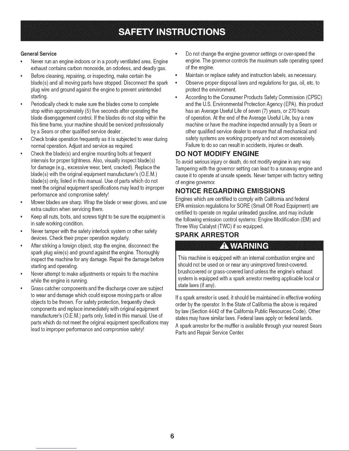
GeneralService
• Neverrunanengineindoorsorinapoorlyventilatedarea.Engine
exhaustcontainscarbonmonoxide,anodorless,anddeadlygas.
• Beforecleaning,repairing,orinspecting,makecertainthe
blade(s)andallmovingpartshavestopped.Disconnectthespark
plugwireandgroundagainsttheenginetopreventunintended
starting.
• Periodicallychecktomakesurethebladescometocomplete
stopwithinapproximately(5)fivesecondsafteroperatingthe
bladedisengagementcontrol.Ifthebladesdonotstopwithinthe
thistimeframe,yourmachineshouldbeservicedprofessionally
byaSearsorotherqualifiedservicedealer.
• Checkbrakeoperationfrequentlyasitissubjectedtowearduring
normaloperation.Adjustandserviceasrequired.
• Checktheblade(s)andenginemountingboltsatfrequent
intervalsforpropertightness.Also,visuallyinspectblade(s)
fordamage(e.g.,excessivewear,bent,cracked).Replacethe
blade(s)withtheoriginalequipmentmanufacturer's(O.E.M.)
blade(s)only,listedinthismanual.Useofpartswhichdonot
meettheoriginalequipmentspecificationsmayleadtoimproper
performanceandcompromisesafety!
• Mowerbladesaresharp.Wrapthebladeorweargloves,anduse
extracautionwhenservicingthem.
• Keepallnuts,bolts,andscrewstighttobesuretheequipmentis
insafeworkingcondition.
• Nevertamperwiththe safetyinterlocksystemorothersafety
devices.Checktheirproperoperationregularly.
• Afterstrikinga foreignobject,stopthe engine,disconnectthe
sparkplugwire(s)andgroundagainsttheengine.Thoroughly
inspectthemachineforanydamage.Repairthedamagebefore
startingandoperating.
• Neverattemptto makeadjustmentsor repairstothemachine
whilethe engineis running.
• Grasscatchercomponentsandthe dischargecoverare subject
towearanddamagewhichcouldexposemovingpartsor allow
objectsto bethrown.Forsafetyprotection,frequentlycheck
componentsand replaceimmediatelywithoriginalequipment
manufacturer's(O.E.M.)partsonly,listedinthis manual.Useof
partswhichdo notmeettheoriginalequipmentspecificationsmay
leadtoimproperperformanceandcompromisesafety!
• Donotchangetheenginegovernorsettingsorover-speedthe
engine.Thegovernorcontrolsthe maximumsafeoperatingspeed
ofthe engine.
Maintainor replacesafetyandinstructionlabels,as necessary.
• Observeproperdisposallawsandregulationsforgas,oil,etc.to
protecttheenvironment.
• Accordingtothe ConsumerProductsSafetyCommission(CPSC)
andthe U.S.EnvironmentalProtectionAgency(EPA),thisproduct
hasanAverageUsefulLifeofseven(7)years,or 270hours
ofoperation.Attheendofthe AverageUsefulLife,buyanew
machineor havethemachineinspectedannuallybya Searsor
otherqualifiedservicedealerto ensurethatallmechanicaland
safetysystemsareworkingproperlyandnot wornexcessively.
Failuretodosocanresultinaccidents,injuriesor death.
DO NOT MODIFY ENGINE
Toavoid seriousinjuryor death,do notmodifyengineinanyway.
Tamperingwiththegovernorsettingcanleadtoa runawayengineand
causeitto operateat unsafespeeds.Nevertamperwithfactorysetting
ofenginegovernor.
NOTICE REGARDING EMISSIONS
Engineswhicharecertifiedto complywithCaliforniaandfederal
EPAemissionregulationsfor SORE(SmallOffRoadEquipment)are
certifiedto operateonregularunleadedgasoline,andmayinclude
thefollowingemissioncontrolsystems:EngineModification(EM)and
ThreeWayCatalyst(TWO)if soequipped.
SPARK ARRESTOR
Thismachineis equippedwithan internalcombustionengineand
shouldnotbe usedonor nearanyunimprovedforest-covered,
brushcoveredorgrass-coveredlandunlesstheengine'sexhaust
systemisequippedwitha sparkarrestormeetingapplicablelocalor
statelaws(if any).
Ifa sparkarrestoris used,it shouldbemaintainedin effectiveworking
orderbythe operator.IntheStateof Californiatheaboveis required
bylaw (Section4442of the CaliforniaPublicResourcesCode).Other
statesmayhavesimilarlaws.Federallawsapplyonfederallands.
A sparkarrestorforthemuffleris availablethroughyournearestSears
PartsandRepairServiceCenter.
6
Page 7
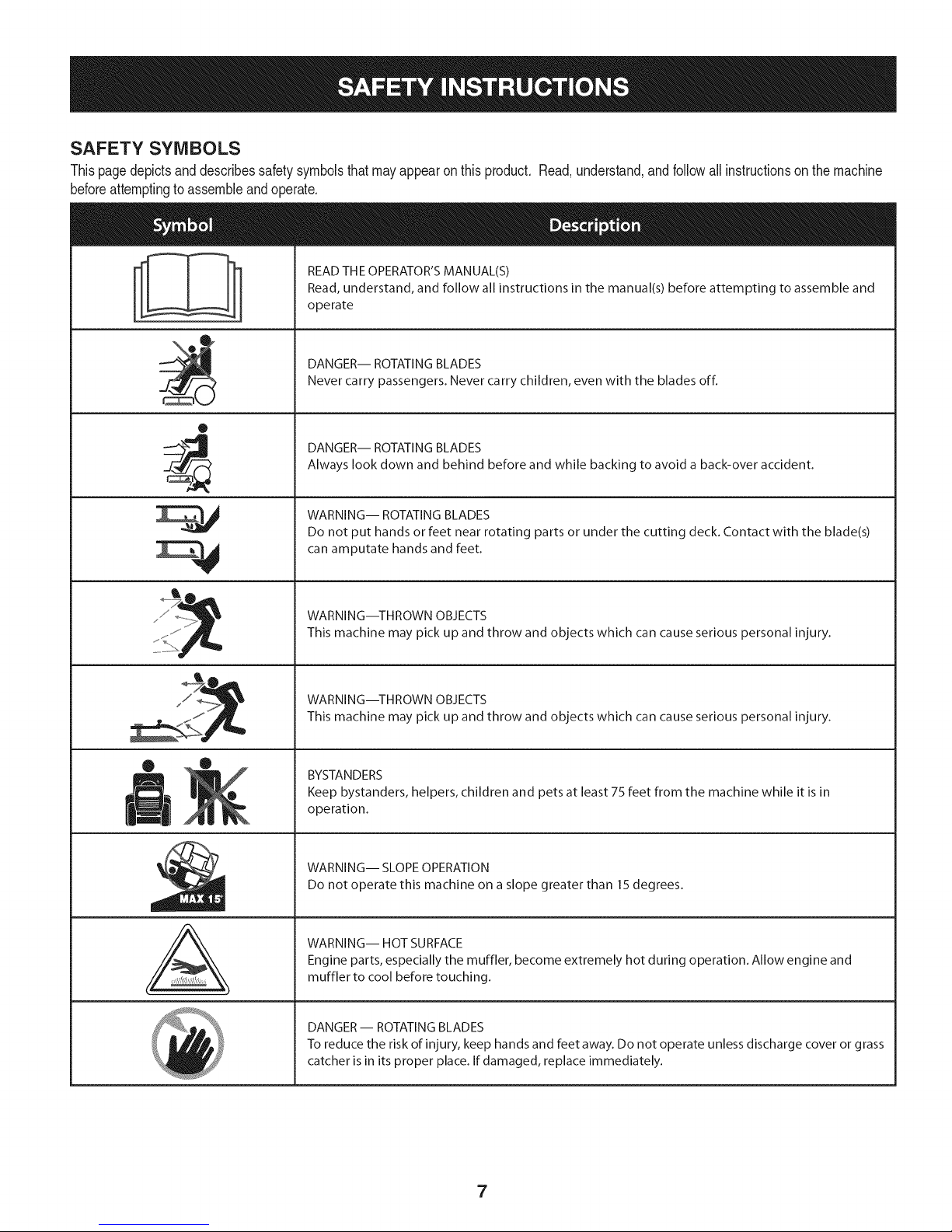
SAFETY SYMBOLS
Thispagedepictsanddescribessafetysymbolsthatmayappearonthis product.Read,understand,andfollowallinstructionson the machine
beforeattemptingtoassembleandoperate.
READ THE OPERATOR'S MANUAL(S)
Read, understand, and follow all instructions in the manual(s) before attempting to assemble and
operate
DANGER-- ROTATING BLADES
Never carry passengers. Never carry children, even with the blades off.
O
DANGER-- ROTATING BLADES
Always look down and behind before and while backing to avoid a back-over accident.
WARNING-- ROTATING BLADES
Do not put hands or feet near rotating parts or under the cutting deck. Contact with the blade(s)
can amputate hands and feet.
A
WARNING--THROWN OBJECTS
This machine may pick up and throw and objects which can cause serious personal injury.
WARNING--THROWN OBJECTS
This machine may pick up and throw and objects which can cause serious personal injury.
BYSTANDERS
Keep bystanders, helpers, children and pets at least 75 feet from the machine while it is in
operation.
WARNING-- SLOPE OPERATION
Do not operate this machine on a slope greater than 15 degrees.
WARNING-- HOT SURFACE
Engine parts, especially the muffler, become extremely hot during operation. Allow engine and
muffler to cool before touching.
DANGER- ROTATING BLADES
To reduce the risk of injury, keep hands and feet away. Do not operate unless discharge cover or grass
catcher is in its proper place. If damaged, replace immediately.
7
Page 8
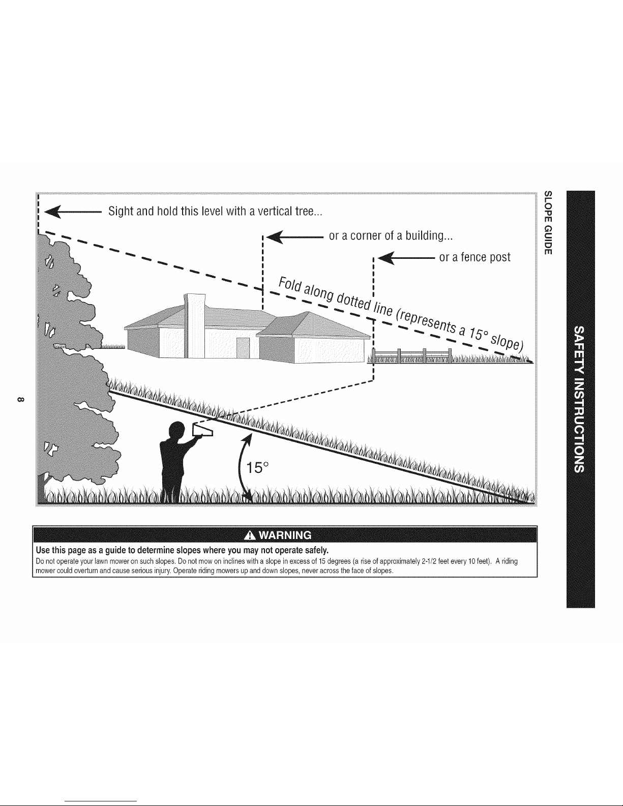
0o
Sight andhold this
i
levelwith avertical tree...
|
I
|
|
I
|
|
|
or acorner of a building...
15 °
Use this page as a guideto determine slopes where you may not operate safely.
Donot operateyourlawnmoweron suchslopes.Donotmowon inclineswitha slopeinexcessof 15degrees(a riseofapproximately2-1/2feetevery10feet). Ariding
mowercouldoverturnandcauseseriousinjury.Operateridingmowersupanddownslopes,neveracrossthe faceofslopes.
Page 9
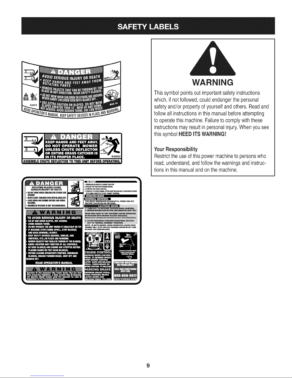
ROTATING BLADES CAUSE
SERIOUS INJURY OR DEATH
• DONOTMOWWHENCHILDRENOROTHERSARE
AROUND
• NEVERCARRYCHILDRENEVENWITHBLaDE(S)OFF.
• LOOKDOWNANDNEMDONEFORSANDWHILE
BACKING.
• MOWINGINREVERSEISNOTRECOMMENDED.
WARNING
Thissymbol points out importantsafety instructions
which, if not followed,could endanger the personal
safety and/or property of yourself and others. Readand
followall instructionsin this manual beforeattempting
to operatethis machine. Failureto comply with these
instructionsmay result in personalinjury.When you see
this symbol HEED ITS WARNING!
Your Responsibility
Restrictthe use ofthis power machineto personswho
read, understand,and followthe warnings and instruc-
tions inthis manualand on themachine.
NOTE: IN BOTH MODES, WHEN OPERATOR LEAVES SEAT,
ENGINE WILL STOP UNLESS PARKING BRAKE IS SET AND
BLAINS AR_ DISEHGAGE_
9
Page 10
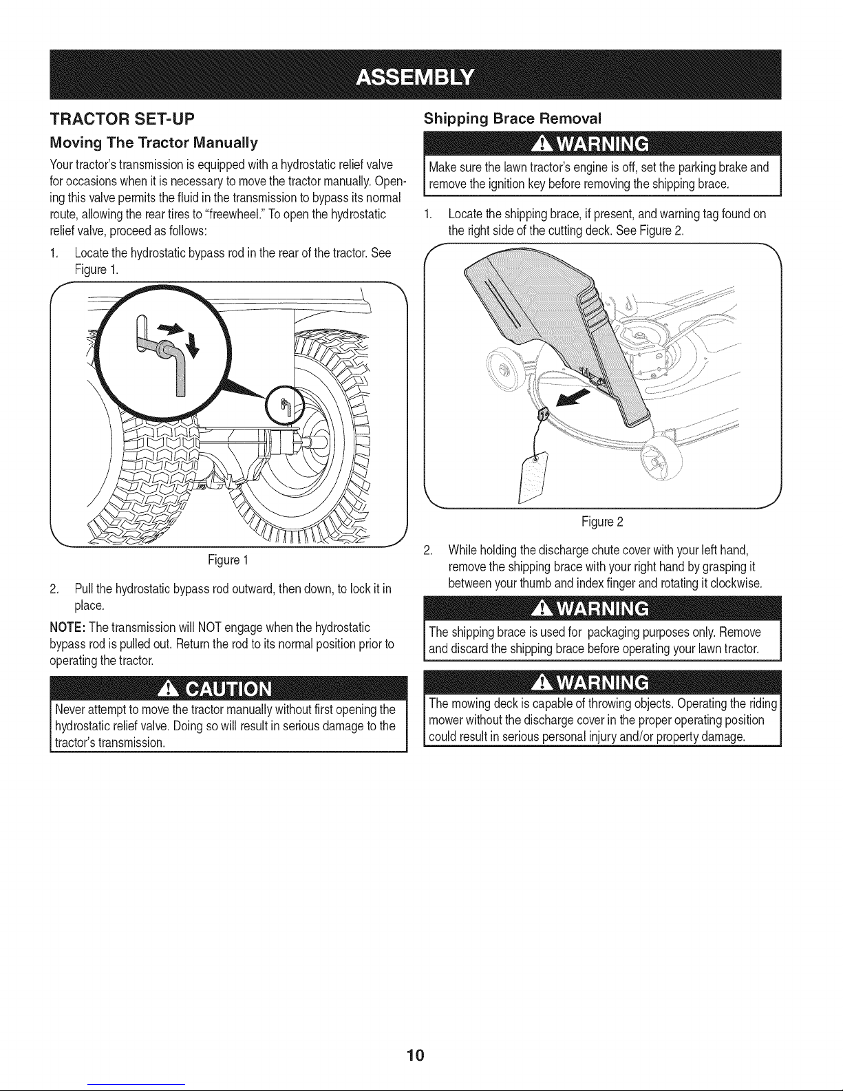
TRACTOR SET-UP
Moving The Tractor Manually
Yourtractor'stransmissionisequippedwitha hydrostaticreliefvalve
foroccasionswhenitis necessarytomovethetractormanually.Open-
ingthisvalvepermitsthefluidinthetransmissionto bypassits normal
route,allowingthereartiresto "freewheel."Toopenthehydrostatic
reliefvalve,proceedasfollows:
1. Locatethehydrostaticbypassrodinthe rearof thetractor.See
Figure1.
Shipping Brace Removal
Makesurethe lawntractor'sengineisoff, setthe parkingbrakeand
removethe ignitionkeybeforeremovingtheshippingbrace.
1. Locatetheshippingbrace,ifpresent,andwarningtagfoundon
the rightsideofthecuttingdeck.SeeFigure2.
Figure1
2. Pullthehydrostaticbypassrodoutward,thendown,to lockit in
place.
NOTE:The transmissionwillNOTengagewhenthehydrostatic
bypassrodis pulledout. Returnthe rodto itsnormalpositionpriorto
operatingthetractor.
Neverattemptto movethetractormanuallywithoutfirstopeningthe
hydrostaticreliefvalve.Doingsowillresultinseriousdamagetothe
tractor'stransmission.
Figure2
.
Whileholdingthe dischargechutecoverwithyourleft hand,
removethe shippingbracewithyourrighthandby graspingit
betweenyourthumband indexfingerand rotatingitclockwise.
Theshippingbraceis usedfor packagingpurposesonly.Remove
anddiscardtheshippingbracebeforeoperatingyourlawntractor.
Themowingdeckis capableofthrowingobjects.Operatingthe riding
mowerwithoutthedischargecoverin theproperoperatingposition
couldresultin seriouspersonalinjuryand/orpropertydamage.
10
Page 11
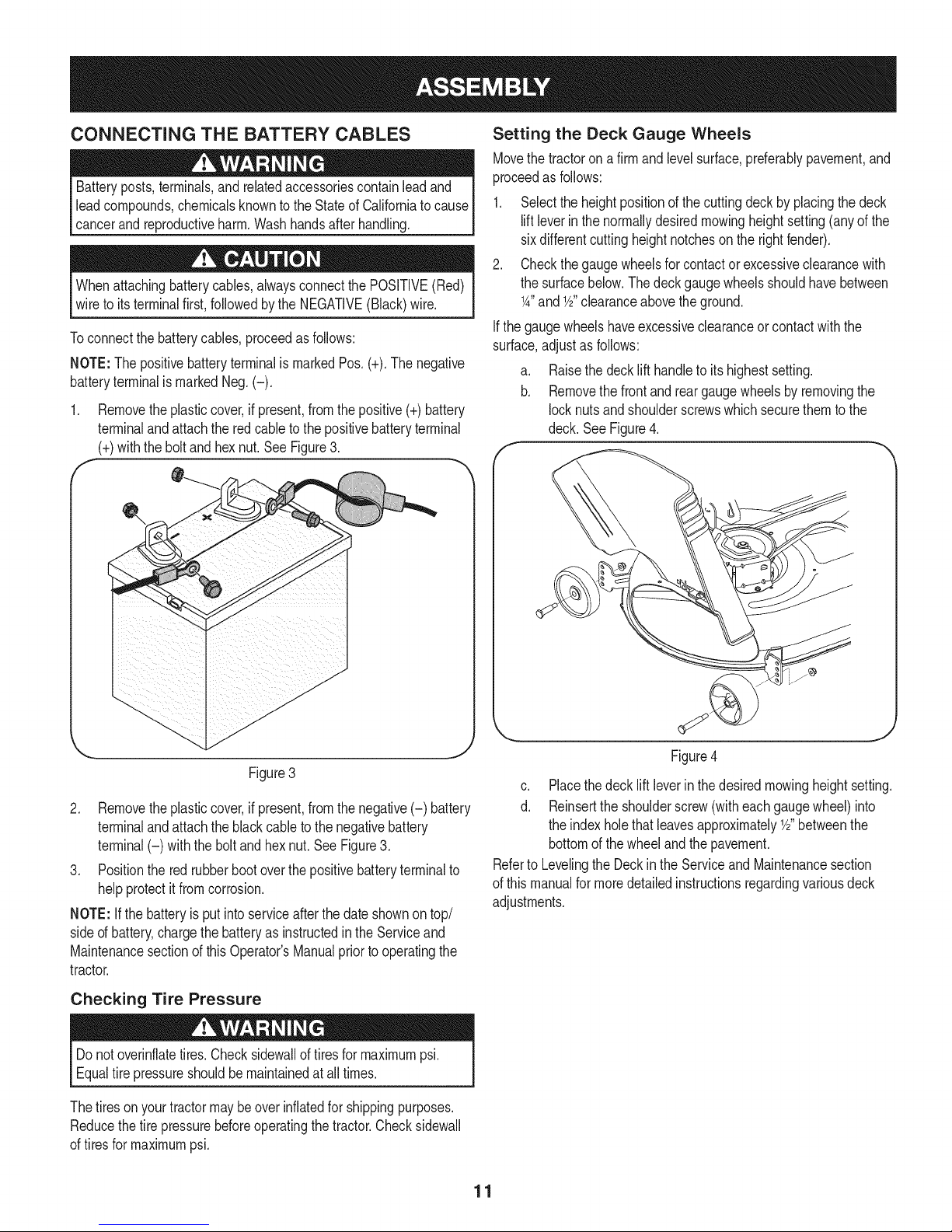
CONNECTING THE BATTERY CABLES
Batteryposts,terminals,andrelatedaccessoriescontainleadand
leadcompounds,chemicalsknowntotheStateofCaliforniatocause
cancerandreproductiveharm.Washhandsafterhandling.
Whenattachingbatterycables,alwaysconnectthe POSiTiVE(Red)
wireto its terminalfirst,followedbythe NEGATIVE(Black)wire.
Toconnectthebatterycables,proceedasfollows:
NOTE:The positivebatteryterminalismarkedPos.(+).The negative
batteryterminalis markedNeg.(-).
1. Removetheplasticcover,if present,fromthepositive(+)battery
terminalandattachthe redcabletothe positivebatteryterminal
(+)withthebolt andhexnut.See Figure3.
f -,
Setting the Deck Gauge Wheels
Movethe tractoron afirmand levelsurface,prderablypavement,and
proceedas follows:
1. Selecttheheightpositionofthecuttingdeckbyplacingthedeck
liftleverinthe normallydesiredmowingheightsetting(anyofthe
sixdifferentcuttingheightnotchesontherightfender).
2. Checkthegaugewheelsfor contactor excessiveclearancewith
thesurfacebelow.The deckgaugewheelsshouldhavebetween
1A"andY2"clearanceabovetheground.
Ifthegaugewheelshaveexcessiveclearanceorcontactwiththe
surface,adjustas follows:
a. Raisethe decklift handleto itshighestsetting.
b. Removethefrontandreargaugewheelsbyremovingthe
locknutsandshoulderscrewswhichsecurethemto the
deck.SeeFigure4.
Figure3
2. Removetheplasticcover,if present,fromthenegative(-) battery
terminalandattachtheblackcableto thenegativebattery
terminal(-) withthebolt andhexnut.SeeFigure3.
3. Positionthe redrubberbootoverthepositivebatteryterminalto
helpprotectit fromcorrosion.
NOTE:Ifthe batteryisput intoserviceafterthe dateshownontop/
sided battery,chargethebatteryasinstructedintheServiceand
Maintenancesectionofthis Operator'sManualpriortooperatingthe
tractor.
Checking Tire Pressure
Donotoverinflatetires.Checksidewallof tiresformaximumpsi.
Equaltirepressureshouldbemaintainedat alltimes.
Thetiresonyour tractormaybeoverinflatedforshippingpurposes.
Reducethetire pressurebeforeoperatingthetractor.Checksidewall
oftiresfor maximumpsi.
c. Placethedecklift leverinthedesiredmowingheightsetting.
d. Reinsertthe shoulderscrew(witheachgaugewheel)into
theindexholethatleavesapproximatelyY2"betweenthe
bottomofthewheelandthepavement.
Referto Levelingthe Deckin the Serviceand Maintenancesection
ofthis manualformoredetailedinstructionsregardingvariousdeck
adjustments.
11
Page 12
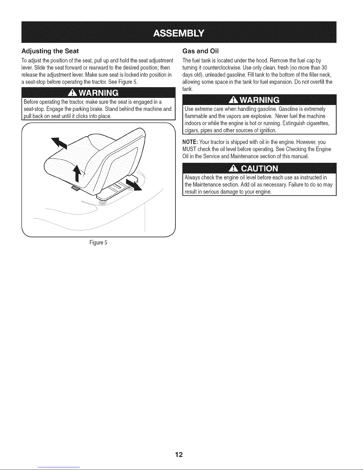
Adjusting the Seat
Toadjustthe positionoftheseat,pullup andholdtheseatadjustment
lever.Slidetheseatforwardor rearwardtothedesiredposition;then
releasetheadjustmentlever.Makesureseatislockedintopositionin
a seat-stopbeforeoperatingthe tractor.SeeFigure5.
Beforeoperatingthe tractor,makesuretheseatisengagedina
seat-stop.Engagethe parkingbrake.Standbehindthemachineand
pullbackon seatuntilitclicksintoplace.
f
,\
Gas and Oil
Thefueltank islocatedunderthehood.Removethefuelcap by
turningit counterclockwise.Useonlyclean,fresh(no morethan30
daysold),unleadedgasoline.Filltanktothebottomofthe fillerneck,
allowingsomespacein thetankfor fuel expansion.Donotoverfillthe
tank.
Useextremecarewhenhandlinggasoline.Gasolineisextremely
flammableandthevaporsare explosive.Neverfuelthemachine
indoorsorwhiletheengineishotor running.Extinguishcigarettes,
cigars,pipesandothersourcesof ignition.
NOTE:Yourtractorisshippedwithoil intheengine.However,you
MUSTchecktheoillevelbeforeoperating.SeeCheckingthe Engine
Oil intheServiceand Maintenancesectionofthismanual.
Alwayschecktheengineoil levelbeforeeachuseas instructedin
theMaintenancesection.Addoil asnecessary.Failuretodo so may
resultinseriousdamagetoyourengine.
Figure5
12
Page 13
f
FueITankCap
Throttle/ChokeControl_
I
FuelLevelIndicator
CupHolder"
IgnitionSwitch
Module
PTO(Blade
Knob
DrivePedal
Pedal
LiffLever
\
Figure6
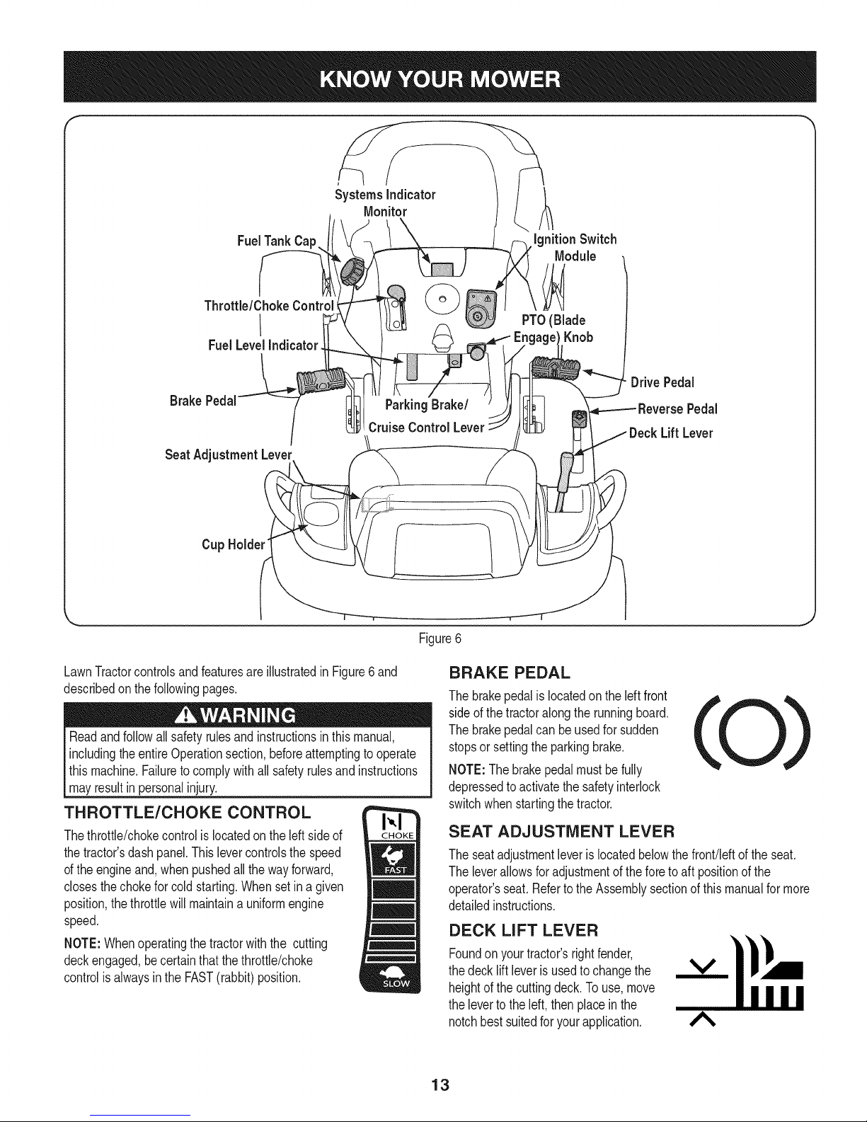
LawnTractorcontrolsandfeaturesareillustratedinFigure6and
describedon thefollowingpages.
Readandfollowallsafetyrulesandinstructionsinthismanual,
includingtheentireOperationsection,beforeattemptingtooperate
this machine.Failuretocomplywithall safetyrulesand instructions
mayresultin personalinjury.
THROTTLE/CHOKE CONTROL
Thethrottle/chokecontrolis locatedon theleftsideof
thetractor'sdashpanel.Thislevercontrolsthespeed
ofthe engineand,whenpushedallthewayforward,
closesthechokeforcold starting.Whensetin agiven
position,thethrottlewillmaintaina uniformengine
speed.
NOTE:Whenoperatingthetractorwiththe cutting
deckengaged,becertainthatthe throttle/choke
controlisalwaysintheFAST(rabbit)position.
BRAKE PEDAL
Thebrakepedalis locatedontheleftfront
sideof thetractoralongthe runningboard.
Thebrakepedalcanbeusedfor sudden
stopsorsettingtheparkingbrake.
NOTE:Thebrakepedalmustbefully
depressedto activatethesafetyinterlock
switchwhenstartingthetractor.
SEAT ADJUSTMENT LEVER
Theseatadjustmentleveris locatedbelowthefront!leftofthe seat.
Theleverallowsforadjustmentoftheforetoaft positionofthe
operator'sseat.RefertotheAssemblysectionofthismanualfor more
detailedinstructions.
DECK LIFT LEVER
Foundonyour tractor'srightfender,
thedecklift leverisusedtochangethe
heightofthecuttingdeck.To use,move
thelevertotheleft, thenplacein the
notchbestsuitedforyourapplication.
A
13
Page 14
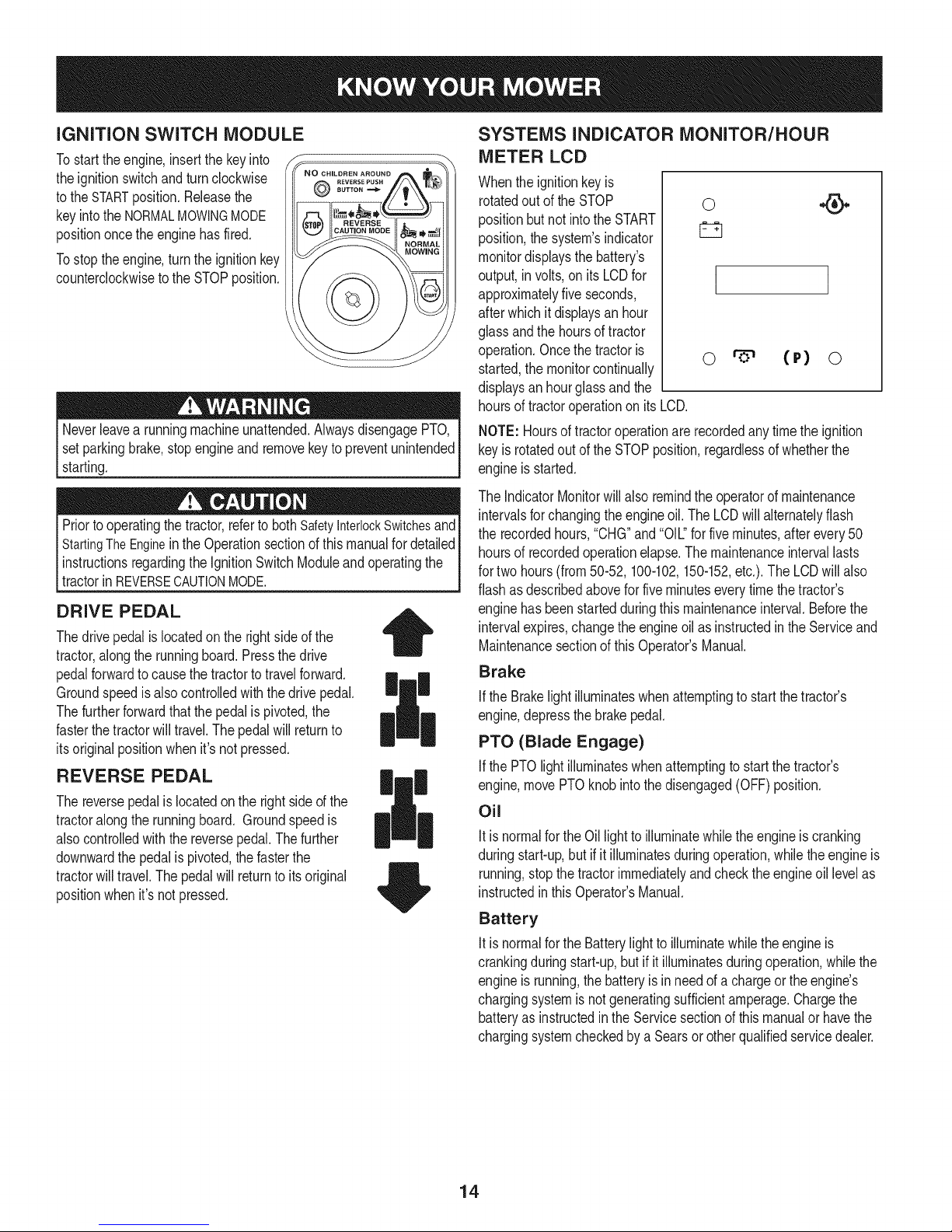
iGNiTiON SWITCH MODULE
Tostart theengine,insertthekeyinto
theignitionswitchand turnclockwise
tothe STARTposition.Releasethe
keyintotheNORMALMOWINGMODE
positiononcethe enginehasfired.
Tostoptheengine,turntheignitionkey
counterclockwiseto the STOPposition.
Neverleavea runningmachineunattended.AlwaysdisengagePTO,
setparkingbrake,stopengineand removekeytopreventunintended
starting.
Priortooperatingthetractor,referto bothSafetyInterlockSwitchesand
StartingTheEnginein theOperationsectionof thismanualfordetailed
instructionsregardingthe IgnitionSwitchModuleandoperatingthe
tractorinREVERSECAUTONMODE. j
8UTTONm_
REVERS£PUSH
DRIVE PEDAL
Thedrivepedalislocatedon therightsideofthe
tractor,alongthe runningboard.Pressthe drive
pedalforwardtocausethe tractortotravelforward.
Groundspeedis alsocontrolledwiththe drivepedal.
Thefurtherforwardthatthepedalispivoted,the
fasterthetractorwill travel.Thepedalwill returnto
itsoriginalpositionwhenit'snotpressed.
|
REVERSE PEDAL
Thereversepedalis locatedonthe rightsideof the
tractoralongthe runningboard. Groundspeedis
alsocontrolledwiththe reversepedal.Thefurther
downwardthe pedalispivoted,thefasterthe
tractorwilltravel.Thepedalwillreturnto itsoriginal
positionwhenit'snotpressed.
SYSTEMS INDICATOR MONITOR/HOUR
METER LCD
Whenthe ignitionkeyis
rotatedout oftheSTOP
positionbutnot intotheSTART
position,thesystem'sindicator
monitordisplaysthebattery's
output,in volts,on its LCDfor
approximatelyfiveseconds,
afterwhichitdisplaysanhour
glassandthehoursof tractor
operation.Oncethetractoris
started,themonitorcontinually
displaysanhourglassandthe
hoursof tractoroperationonitsLCD.
NOTE:Hoursof tractoroperationarerecordedanytimethe ignition
keyis rotatedoutoftheSTOPposition,regardlessof whetherthe
engineisstarted.
TheIndicatorMonitorwillalso remindtheoperatorofmaintenance
intervalsforchangingtheengineoil.The LCDwill alternatelyflash
the recordedhours,"CHG"and"OIL."for fiveminutes,afterevery50
hoursof recordedoperationelapse.Themaintenanceintervallasts
fortwo hours(from50-52, 100-102,150-152,etc.).TheLCDwillalso
flashasdescribedaboveforfiveminuteseverytimethe tractor's
enginehasbeenstartedduringthismaintenanceinterval.Beforethe
intervalexpires,changetheengineoilas instructedinthe Serviceand
Maintenancesectionof thisOperator'sManual.
Brake
ifthe Brakelightilluminateswhenattemptingto start thetractor's
engine,depressthebrakepedal.
PTO (Blade Engage)
IfthePTOlightilluminateswhenattemptingto startthetractor's
engine,movePTOknobinto thedisengaged(OFF)position.
Oil
Itis normalfortheOillightto illuminatewhiletheengineiscranking
duringstart-up,but if it illuminatesduringoperation,whiletheengineis
running,stopthetractorimmediatelyandcheckthe engineoil levelas
instructedinthis Operator'sManual.
Battery
Itis normalfortheBatterylighttoilluminatewhiletheengineis
crankingduringstart-up,butif it illuminatesduringoperation,whilethe
engineisrunning,thebatteryisinneedofa chargeortheengine's
chargingsystemisnotgeneratingsufficientamperage.Chargethe
batteryas instructedin theServicesectionof thismanualor havethe
chargingsystemcheckedbyaSearsor otherqualifiedservicedealer.
0
I
o (P) o
14
Page 15
FUEL LEVEL INDICATOR
TheFuelLevelIndicatorislocatedon the leftsideofthe tractor's
dashandindicatestheamountof fuelin thegastank.
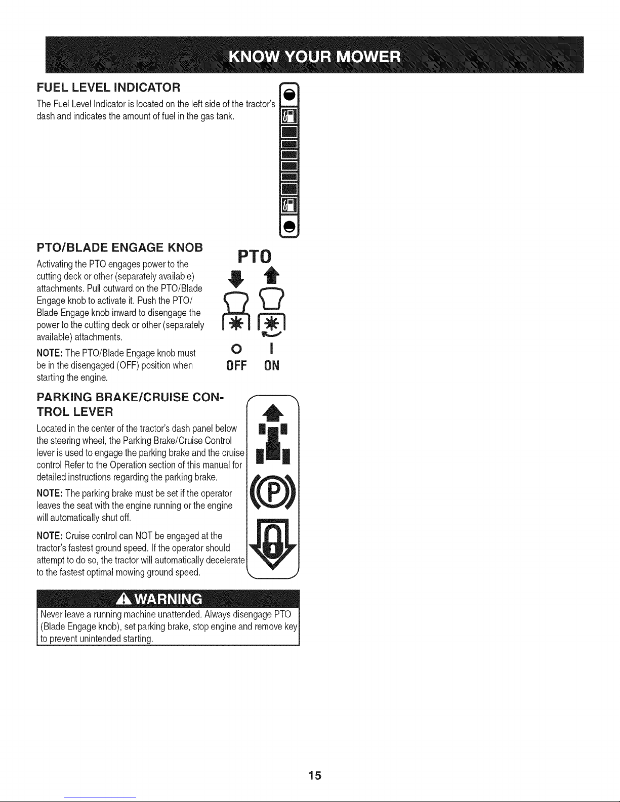
PTO/BLADE ENGAGE KNOB
Activatingthe PTOengagespowerto the
cuttingdeckorother(separatelyavailable)
attachments.Pulloutwardonthe PTO/Blade
Engageknobto activateit. PushthePTO/
BladeEngageknobinwardto disengagethe
powertothecuttingdeckorother(separately
available)attachments.
NOTE:The PTO/BladeEngageknobmust
be inthedisengaged(OFF)positionwhen
startingtheengine.
PTO
OFF ON
PARKING BRAKE/CRUISE CON-
TROL LEVER
Locatedinthecenterof the tractor'sdashpanelbelow
thesteeringwheel,theParkingBrake/CruiseControl
leveris usedtoengagethe parkingbrakeandthecruise
controlRefertothe Operationsectionofthismanualfor
detailedinstructionsregardingtheparkingbrake.
NOTE:The parkingbrakemustbesetiftheoperator
leavestheseatwiththe enginerunningor theengine
willautomaticallyshutoff.
NOTE:Cruisecontrolcan NOTbeengagedat the
tractor'sfastestgroundspeed.If theoperatorshould
attempttodoso,the tractorwillautomaticallydecelerate
tothe fastestoptimalmowinggroundspeed.
(BladeEngageknob),setparkingbrake,stopengineand remove
topreventunintendedstarting.
15
Page 16
SAFETY iNTERLOCK SWITCH ES
Thistractoris equippedwitha safetyinterlocksystemfor the protection
ofthe operator.Iftheinterlocksystemshouldevermalfunction,do not
operatethetractor.Contacta Searsorotherqualifiedservicedealer.
• The safetyinterlocksystempreventstheenginefromcrankingor
startingunlessthe parkingbrakeisengaged,andthe PTO(Blade
Engage)handleisinthe disengaged(OFF)position.
Theenginewill automaticallyshutoffif theoperatorleavesthe
seatbeforeengagingtheparkingbrake.
• TheelectricPTO(BladeEngage)clutchwill automaticallyshut
off iftheoperatorleavesthetractor'sseatwiththe PTO(Blade
Engage)knobinthe engaged(ON)position,regardlessof
whetherthe parkingbrakeisengaged.
• Withthe ignitionkeyinthe NORMALMOWINGposition,the
electricPTO(BladeEngage)clutchwillautomaticallyshutoffif
thePTO(BladeEngage)knobismovedintothe engaged(ON)
positionwiththedrive pedalinpositionfor reversetravel.
Donotoperatethetractorif the interlocksystemis malfunctioning.
Thissystemwasdesignedfor your safetyandprotection.
STARTING THE ENGINE
NOTE:Referto theAssembly& Set-Upsectionof thismanualfor
GasolineandOilfill-up instructions.
STOPPING THE ENGINE
Ifyoustrikea foreignobject,stopthe engineanddisconnectthe
sparkplugwire(s).Thoroughlyinspectthe machineforanydamage.
Repairthedamagebeforerestartingandoperating.
1. Ifthebladesareengaged,placethe PTO/BladeEngageknobin
thedisengaged(OFF)position.
2. PlacethethrottlecontrolneartheSLOWposition.
3. Turnthe ignitionkeycounterclockwisetotheSTOPposition.
4. Removethe keyfromthe ignitionswitchtopreventunintended
starting.
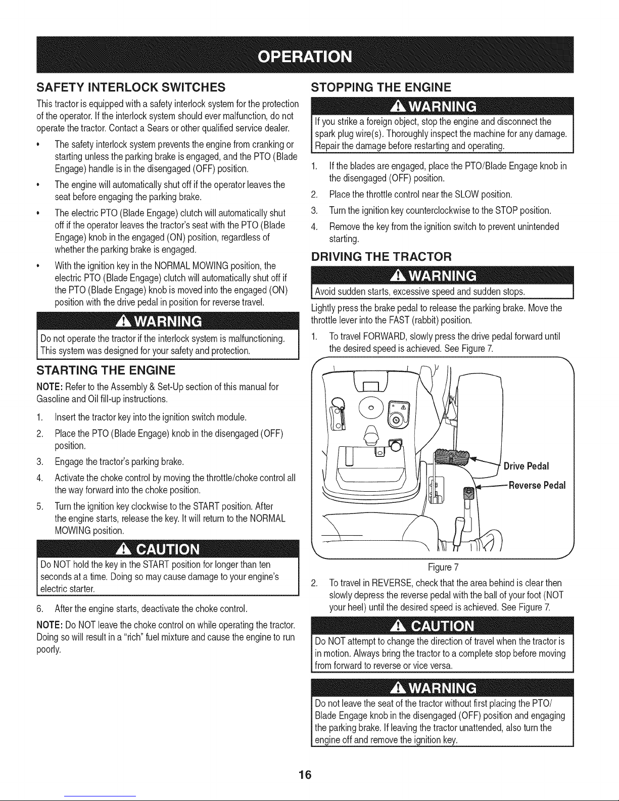
DRIVING THE TRACTOR
Avoidsuddenstarts,excessivespeedandsuddenstops.
Lightlypressthebrakepedalto releasetheparkingbrake.Movethe
throttleleverintothe FAST(rabbit)position.
1. TotravelFORWARD,slowlypressthe drivepedalforwarduntil
thedesiredspeedis achieved.SeeFigure7.
,
1. Insertthe tractorkeyintothe ignitionswitchmodule.
2. Placethe PTO(BladeEngage)knobinthe disengaged(OFF)
position.
3. Engagethetractor'sparkingbrake.
4. Activatethechokecontrolby movingthethrottle/chokecontrolall
thewayforwardinto thechokeposition.
5. Turntheignitionkeyclockwisetothe STARTposition.After
theenginestarts,releasethekey.Itwill returntotheNORMAL
MOWINGposition.
DoNOTholdthe keyinthe STARTpositionfor longerthanten
secondsata time.Doingso maycausedamagetoyourengine's
electricstarter.
6. Aftertheenginestarts,deactivatethechokecontrol.
NOTE:Do NOTleavethechokecontrolon whileoperatingthetractor.
Doingso willresultina "rich"fuelmixtureandcausetheengineto run
poorly.
ReversePedal
Figure7
2. TotravelinREVERSE,checkthattheareabehindisclearthen
slowlydepressthe reversepedalwiththeballof yourfoot(NOT
yourheel)untilthedesiredspeedisachieved.SeeFigure7.
DoNOTattemptto changethedirectionoftravelwhenthetractoris
inmotion.Alwaysbringthetractortoa completestopbeforemoving
fromforwardtoreverseorviceversa.
Donot leavetheseatof thetractorwithoutfirstplacingthePTO/
BladeEngageknobinthe disengaged(OFF)positionandengaging
theparkingbrake.Ifleavingthetractorunattended,alsoturnthe
engineoff andremovetheignitionkey.
16
Page 17
REVERSE CAUTION MODE
TheREVERSECAUTIONMODEpositionof thekeyswitchmodule
allowsthetractorto beoperatedinreversewiththeblades(PTO)
engaged.
NOTE:Mowinginreverseisnotrecommended.
Useextremecautionwhileoperatingthetractorin theREVERSE
CAUTIONMODE.Alwayslookdownand behindbeforeandwhile
backing.Donotoperatethetractorwhenchildrenor othersare
around.Stopthetractorimmediatelyif someoneentersthearea.
Touse theREVERSECAUTIONMODE:
NOTE:The operatorMUSTbe seatedinthetractorseat.
DRIVING ON SLOPES
Referto the SLOPEGUIDEon page8 to helpdetermineslopeswhere
youmayoperatethetractorsafely.
Donot mowon inclineswitha slopeinexcessof 15degrees(a rise
approximately2-1/2feetevery10feet).Thetractorcouldoverturnanc
causeseriousinjury.
• Mowupanddownslopes,NEVERacross.
• Exerciseextremecautionwhenchangingdirectionon slopes.
• Watchforholes,ruts,bumps,rocks,or otherhiddenobjects.
Uneventerraincouldoverturnthe machine.Tallgrasscanhide
obstacles.
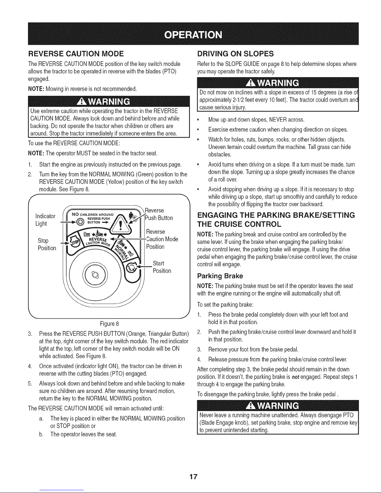
1. Starttheengineaspreviouslyinstructedonthe previouspage. •
2. TurnthekeyfromtheNORMALMOWING(Green)positiontothe
REVERSECAUTIONMODE(Yellow)positionofthe keyswitch
module.SeeFigure8.
, _"_ Reverse
i_Push Button
II1Reverse
Stop
Position
\ j
Figure8
3. PresstheREVERSEPUSHBUTTON(Orange,TriangularButton)
atthe top,rightcornerof thekeyswitchmodule.Theredindicator
lightat thetop,leftcornerofthekeyswitchmodulewillbe ON
whileactivated.SeeFigure8.
4. Onceactivated(indicatorlightON),thetractorcan bedrivenin
reversewiththe cuttingblades(PTO)engaged.
5. Alwayslookdownand behindbeforeandwhilebackingtomake
surenochildrenarearound.Afterresumingforwardmotion,
returnthe keytotheNORMALMOWINGposition.
TheREVERSECAUTIONMODEwill remainactivateduntil:
Mode
Position
Position
Start
Avoidturnswhendrivingona slope.If a turnmustbe made,turn
downthe slope.Turningupaslopegreatlyincreasesthe chance
ofa rollover.
Avoidstoppingwhendrivingupa slope.If it is necessarytostop
whiledrivingup a slope,startupsmoothlyandcarefullyto reduce
thepossibilityof flippingthetractoroverbackward.
ENGAGING THE PARKING BRAKE/SETTING
THE CRUISE CONTROL
NOTE:Theparkingbreakandcruisecontrolarecontrolledbythe
samelever.Ifusingthe brakewhenengagingtheparkingbrake/
cruisecontrollever,theparkingbrakewillengage.Ifusingthe drive
pedalwhenengagingtheparkingbrake/cruisecontrollever,the cruise
controlwillengage.
Parking Brake
NOTE:Theparkingbrakemustbesetif theoperatorleavestheseat
withtheenginerunningortheenginewillautomaticallyshutoff.
Tosetthe parkingbrake:
1. Pressthebrakepedalcompletelydownwith yourleftfootand
holditinthat position.
2. Pushtheparkingbrake/cruisecontrolleverdownwardandholdit
inthatposition.
3. Removeyourfootfromthebrakepedal.
4. Releasepressurefromtheparkingbrake/cruisecontrollever.
Aftercompletingstep3,the brakepedalshouldremaininthedown
position.Ifitdoesn't,theparkingbrakeisnotengaged.Repeatsteps1
through4 toengagethe parkingbrake.
Todisengagetheparkingbrake,lightlypressthebrakepedal.
a. Thekeyisplacedin eithertheNORMALMOWINGposition
orSTOPpositionor
b. Theoperatorleavestheseat.
(BladeEngageknob),setparkingbrake,stopengineandremove
to preventunintendedstarting.
17
Page 18
CruiseControl
Neverengagethe cruisecontrolleverwhiletravelinginreverse.
Tosetthe cruisecontrol:
1. Slowlypresstheupperportionof thedrivepedalwithyour right
footuntilthe desiredspeedisachieved.
2. Lightlypresstheparkingbrake/cruisecontrolleverdownwardand
holditin thatposition.
3. Removeyourfootfromthedrive pedal.
4. Releasepressurefromtheparkingbrake/cruisecontrollever.
Aftercompletingstep3, thedrivepedalshouldremaininthedown
positionandthetractorwillmaintainthesameforwardspeed.If it
doesn't,thecruisecontrolisnotengaged.Repeatsteps1through4to
engagethecruisecontrol.
Todisengagethe cruisecontrol,lightlypressthedrivepedalor the
brakepedal.
NOTE:Cruisecontrolcannotbesetat the tractor'sfastestground
speed.If theoperatorshouldattempttodo so,thetractorwillautomati-
callydecelerateto thefastestoptimalmowinggroundspeed.
Tochangethedirectionof travelfromforwardtoreversewhencruise
controlisengaged,pressthebrakepedaltodisengagethecruise
controlandbringthetractortoa completestop.Thenslowlypressthe
reversepedalwiththeballof yourfoottotravelinreverse.
USING THE DECK LIFT LEVER
Toraisethecuttingdeck,movethe decklift leverto the left,thenplace
itin thenotchbestsuitedforyourapplication.
OPERATING THE HEADLIGHTS
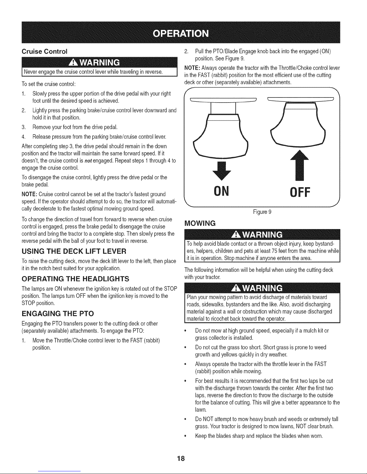
2. Pullthe PTO/BladeEngageknobbackinto theengaged(ON)
position.SeeFigure9.
NOTE:Alwaysoperatethetractorwiththe Throttle/Chokecontrollever
in theFAST(rabbit)positionforthemostefficientuseof thecutting
deckor other(separatelyavailable)attachments.
f -,
ON OFF
Figure9
MOWING
Tohelpavoidbladecontactora thrownobjectinjury,keepbystand-
ers,helpers,childrenandpetsat least75feetfromthe machinewhile
it isin operation.Stopmachineif anyoneentersthearea.
Thefollowinginformationwillbehelpfulwhenusingthecuttingdeck
withyourtractor.
ThelampsareONwhenevertheignitionkeyisrotatedoutoftheSTOP
position.ThelampsturnOFFwhentheignitionkeyis movedtothe
STOPposition.
ENGAGING THE PTO
Engagingthe PTOtransferspowertothecuttingdeckor other
(separatelyavailable)attachments.Toengagethe PTO:
1. MovetheThrottle/ChokecontrollevertotheFAST(rabbit)
position.
Planyourmowingpatternto avoiddischargeofmaterialstoward
roads,sidewalks,bystandersandthelike.Also,avoiddischarging
materialagainstawallorobstructionwhichmaycausedischarged
materialtoricochetbacktowardtheoperator.
• Donotmowat highgroundspeed,especiallyif a mulchkitor
grasscollectoris installed.
• Donotcutthegrasstooshort. Shortgrassis proneto weed
growthandyellowsquicklyindryweather.
• Alwaysoperatethetractorwiththe throttleleverinthe FAST
(rabbit)positionwhilemowing.
• Forbestresultsit is recommendedthatthefirsttwolapsbecut
withthedischargethrowntowardsthe center.Afterthefirsttwo
laps, reversethedirectionto throwthedischargeto theoutside
forthe balanceofcutting.Thiswill giveabetterappearancetothe
lawn.
DoNOTattemptto mowheavybrushand weedsorextremelytall
grass.Yourtractorisdesignedtomowlawns,NOTclearbrush.
• Keepthebladessharpandreplacethebladeswhenworn.
18
Page 19
Beforeperforminganytypeofmaintenance/service,disengageall
controlsandstoptheengine.Waituntilallmovingpartshavecometo
acompletestop.Disconnectsparkplugwireandgroundit againstthe
engineto preventunintendedstarting.Alwayswearsafetyglassesduring
operationorwhileperforminganyadjustmentsorrepairs.
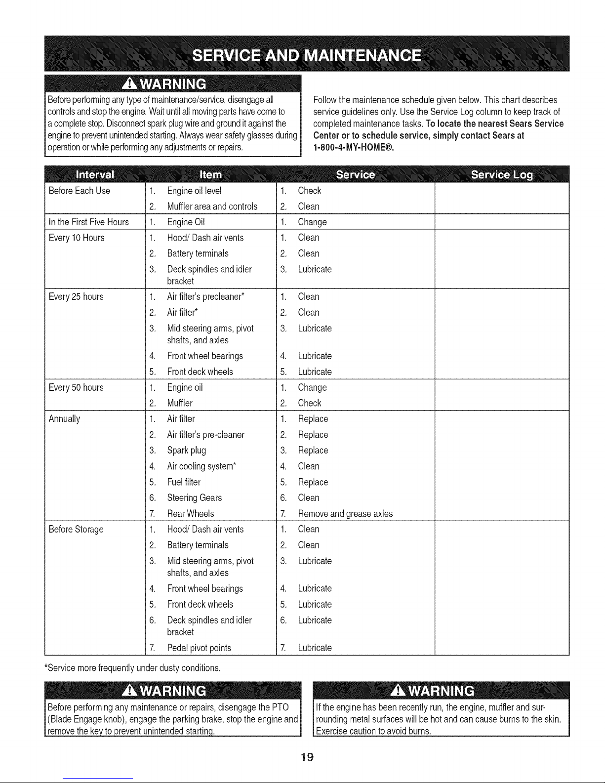
Followthe maintenanceschedulegivenbelow.Thischartdescribes
serviceguidelinesonly.Usethe ServiceLogcolumnto keeptrackof
completedmaintenancetasks.Tolocate the nearest SearsService
Centeror to scheduleservice,simplycontactSearsat
1-800-4-MY-HOME®.
BeforeEachUse
Inthe FirstFiveHours
Every10Hours
Every25 hours
Every50 hours
Annually
BeforeStorage
1. Engineoillevel
2. Mufflerareaandcontrols
1. EngineOil
1. Hood/Dashair vents
2. Batteryterminals
3. Deckspindlesandidler
bracket
1. Airfilter'sprecleaner*
2. Airfilter*
3. Midsteeringarms,pivot
shafts,andaxles
4. Frontwheelbearings
5. Frontdeckwheels
1. Engineoil
2. Muffler
1. Airfilter
2. Airfilter'spre-cleaner
3. Sparkplug
4. Aircoolingsystem*
5. Fuelfilter
6. SteeringGears
7. RearWheels
1. Hood/Dashair vents
2. Batteryterminals
3. Midsteeringarms,pivot
shafts,andaxles
4. Frontwheelbearings
5. Frontdeckwheels
6. Deckspindlesandidler
bracket
7. Pedalpivotpoints
1. Check
2. Clean
1. Change
1. Clean
2. Clean
3. Lubricate
1. Clean
2. Clean
3. Lubricate
4. Lubricate
5. Lubricate
1. Change
2. Check
1. Replace
2. Replace
3. Replace
4. Clean
5. Replace
6. Clean
7. Removeandgreaseaxles
1. Clean
2. Clean
3. Lubricate
4. Lubricate
5. Lubricate
6. Lubricate
7. Lubricate
*Servicemorefrequentlyunderdustyconditions.
_reventunintendedstartin(
Iftheenginehas beenrecentlyrun,the engine,mufflerandsur-
roundingmetalsurfaceswill behot andcancauseburnsto theskin.
Exercisecautiontoavoidburns.
19
Page 20
CUTTING DECK REMOVAL
Placethe PTO/BladeEngageknobinthe disengaged(OFF)
positionandengagetheparkingbrake.
.
Lowerthedeckbymovingthedeck liftleverintothe bottomnotch
ontherightfender.
.
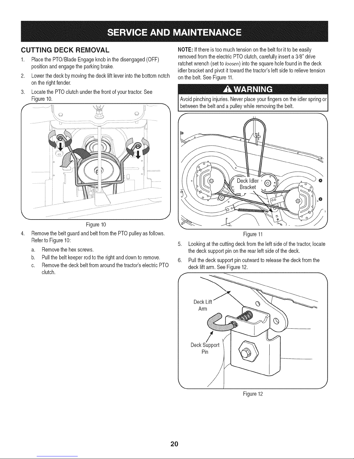
LocatethePTOclutchunderthe frontof yourtractor.See
Figure10.
f
:td
NOTE:Ifthere is toomuchtensionon thebeltfor ittobe easily
removedfromthe electricPTOclutch,carefullyinserta3/8"drive
ratchetwrench(setto loosen)intothesquareholefound inthe deck
idlerbracketandpivotit towardthe tractor'sleftside to relievetension
on thebelt.SeeFigure11.
Avoidpinchinginjuries.Neverplaceyourfingersonthe idlerspringor
betweenthebeltanda pulleywhileremovingthebelt.
Figure10
.
Removethe beltguardand beltfromthePTOpulleyasfollows.
RefertoFigure10:
a. Removethehexscrews.
b. Pullthebeltkeeperrodtotherightanddownto remove.
c. Removethedeckbeltfromaroundthetractor'selectricPTO
clutch.
Figure11
5. Lookingatthecuttingdeckfromtheleftside of thetractor,locate
thedecksupportpinon therearleftsideof thedeck.
6. Pullthe decksupportpinoutwardto releasethe deckfromthe
decklift arm.SeeFigure12.
DeckLift (_
Arm
DeckPinSupport
Figure12
2O
Page 21
.
8.
CHANGING THE DECK BELT
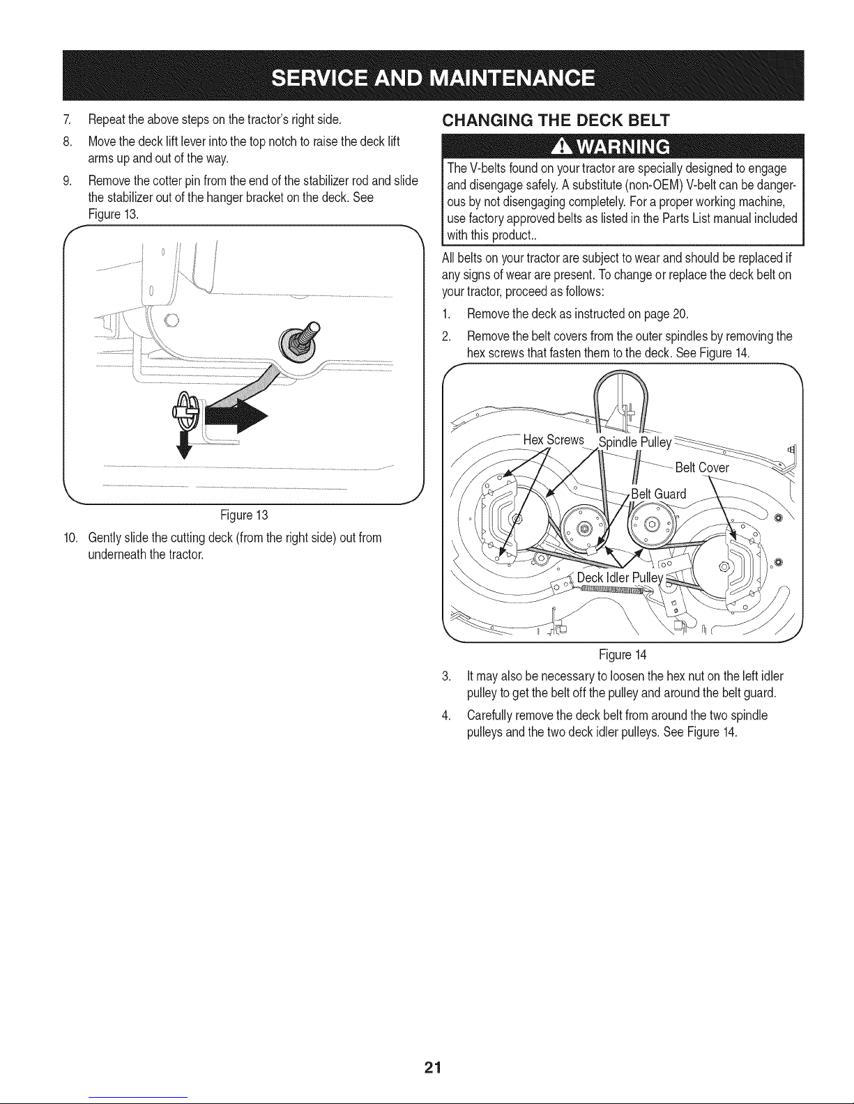
.
f
Figure13
10. Gentlyslidethecuttingdeck(fromtherightside)out from
underneaththetractor.
TheV-beltsfoundon yourtractorarespeciallydesignedtoengage
anddisengagesafely.A substitute(non-OEM)V-beltcan bedanger-
ousby notdisengagingcompletely.Fora properworkingmachine,
usefactoryapprovedbeltsas listedin the PartsListmanualincluded
withthis product..
All beltsonyourtractoraresubjectto wearandshouldbereplacedif
anysignsof weararepresent.Tochangeorreplacethedeckbelton
yourtractor,proceedasfollows:
1. Removethedeckasinstructedon page20.
2. Removethe beltcoversfromtheouterspindlesbyremovingthe
hexscrewsthatfastenthemtothe deck.SeeFigure14.
.....HexScrews 3indlePulle'
J
Figure14
3. Itmayalsobe necessarytoloosenthe hexnutonthe left idler
pulleytogetthe beltoff thepulleyandaroundthe belt guard.
4. Carefullyremovethedeckbeltfromaroundthe two spindle
pulleysandthe twodeckidlerpulleys.SeeFigure14.
21
Page 22
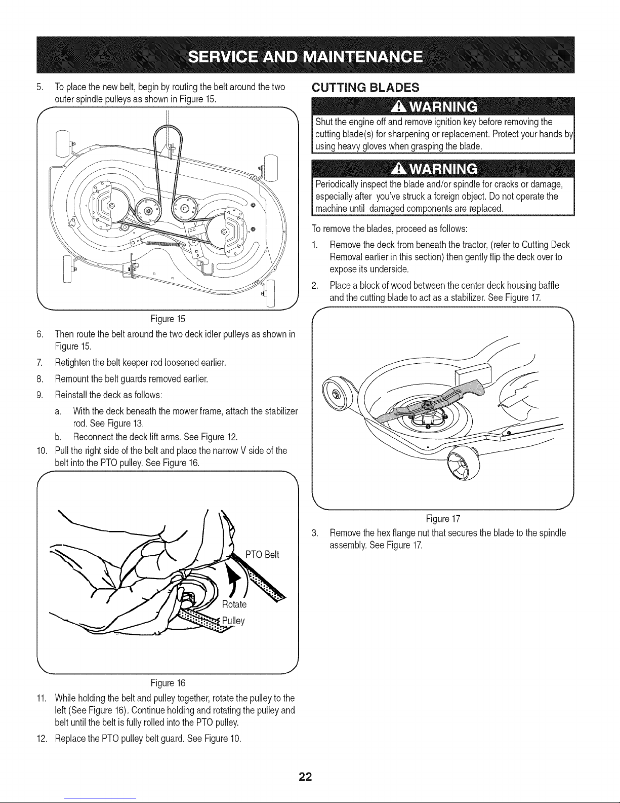
.
Toplacethenewbelt,beginbyroutingthebeltaroundthe two
outerspindlepulleysas shownin Figure15.
Figure15
6. Thenroutethebeltaroundthe twodeckidlerpulleysas shownin
Figure15.
7. Retightenthebeltkeeperrodloosenedearlier.
8. Remountthebeltguardsremovedearlier.
9. Reinstallthedeckasfollows:
a. Withthedeck beneaththemowerframe,attachthestabilizer
rod.SeeFigure13.
b. Reconnectthedeck liftarms.SeeFigure12.
10. Pulltherightside ofthe beltandplacethenarrowVside ofthe
beltintothePTOpulley.SeeFigure16.
CUTTING BLADES
Shutthe engineoff andremoveignitionkeybeforeremovingthe
cuttingblade(s)forsharpeningor replacement.Protectyourhands
usingheavygloveswhengraspingthe blade.
Periodicallyinspectthebladeand/orspindlefor cracksordamage,
especiallyafter you'vestrucka foreignobject.Donotoperatethe
machineuntil damagedcomponentsarereplaced.
Toremovetheblades,proceedasfollows:
1. Removethedeckfrombeneaththetractor,(referto CuttingDeck
Removalearlierin thissection)thengentlyflip thedeckoverto
exposeits underside.
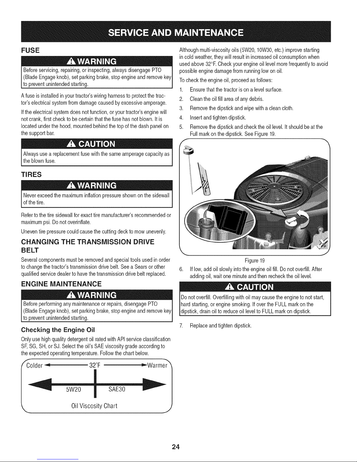
2. Placea blockofwoodbetweenthecenterdeckhousingbaffle
andthecuttingbladeto actasa stabilizer.See Figure17.
Figure16
11. Whileholdingthe beltandpulleytogether,rotatethepulleytothe
left(See Figure16).Continueholdingandrotatingthepulleyand
beltuntilthebeltis fullyrolledinto the PTOpulley.
12. Replacethe PTOpulleybeltguard.SeeFigure10.
Figure17
3. Removethe hexflangenut thatsecuresthebladetothespindle
assembly.SeeFigure17.
PTOBelt
!ey
J
22
Page 23

Toproperlysharpenthecuttingblades,removeequalamounts
4. Jump Starting
ofmetalfromboth endsofthe bladesalongthecuttingedges,
paralleltothetrailingedge,ata 250.300angle.Alwaysgrindeach
cuttingbladeedgeequallyto maintainproperbladebalance.See
Figure18.
Neverjump starta damagedor frozenbattery.Becertainthevehicles
do nottouchandignitionsareoff.Donotallowcableclampsto touch.
1. Connectthe positive(+)cabletopositive(+)postofyourtractor's
Ifthecuttingedgeofthebladehas previouslybeensharpened,orif
anymetalseparationispresent,replacethebladeswithnewones.
dischargedbattery.
2. Connectthe otherendofthe cableto thepositive(+)postof the
jumperbattery.
3. Connectthe negative(-) cabletothe negative(-) postof the
A poorlybalancedbladewillcauseexcessivevibration,maycause
damageto thetractorand/orresultinpersonalinjury.
jumperbattery.
4. Makethefinalconnectionon theengineblockof thetractor,away
fromthebattery.Attachtoan unpaintedparttoassurea good
connection.
Ifthejumperbatteryis installedona vehicle(i.e.car,truck),do NOT
startthe vehicle'senginewhenjumpstartingyourtractor.
5. Startthe tractor(asinstructedintheOperationsectionofthis
manual).
6. Setthetractor'sparkingbrakebeforeremovingthejumpercables.
Removecablesinreverseorderofconnection.
Figure18
.
Testtheblade'sbalanceusingabladebalancer.Grindmetalfrom
theheavyside untilit balancesevenly.
NOTE:Whenreplacingtheblade,besuretoinstallthebladewith
thesideoftheblademarked"Bottom"(or witha partnumber
stampedinit) facingthegroundwhenthemowerisintheoperat-
ingposition.
Useatorquewrenchto tightenthe bladespindlehexflangenutto
between70ft-lbs and90ft-lbs.
BATTERY
Batteryposts,terminals,andrelatedaccessoriescontainleadand
leadcompounds,chemicalsknowntotheStateofCaliforniatocause
cancerandreproductiveharm.Washhandsafterhandling.
Charging
Batteriesgiveoff an explosivegas whilecharging.ChargethebatteryI
in a wellventilatedareaandkeepawayfroman openflameorpilot I
lightas on a waterheater,spaceheater,furnace,clothesdryeror I
othergas appliances. ..J
Whenchargingyourtractor'sbattery,useonlyachargerdesignedfor
12Vlead-acidbatteries.Readyourbatterycharger'sOwner'sManual
priortochargingyourtractor'sbattery.Alwaysfollowitsinstructions
andheeditswarnings.
Ifyourtractorhasnotbeenput intousefor anextendedperiodoftime,
chargethe batteryasfollows:
1. Setyourbatterychargertodelivera maxof 10amperes.
2. Ifyour batterychargerisautomatic,chargethe batteryuntilthe
chargerindicatesthatchargingis complete.If thechargerisnot
automatic,chargefor nofewerthaneighthours.
If removingthe battery,disconnecttheNEGATIVE(Black)wirefrom
itsterminalfirst,followedbythePOSITIVE(Red)wire.Whenreinstall-
ingthebattery,alwaysconnectthePOSITIVE(Red)wireits terminal
first,followedbythe NEGATIVE(Black)wire.
23
Page 24
FUSE
Beforeservicing,repairing,or inspecting,alwaysdisengagePTO
(BladeEngageknob),setparkingbrake,stopengineand remove
topreventunintendedstarting.
Afuse isinstalledinyourtractor'swiringharnessto protectthetrac-
tor'selectricalsystemfromdamagecausedbyexcessiveamperage.
Iftheelectricalsystemdoesnotfunction,or yourtractor'senginewill
notcrank,firstchecktobecertainthatthefusehasnot blown.It is
locatedunderthehood,mountedbehindthe top ofthedashpanelon
thesupportbar.
Alwaysusea replacementfusewiththe sameamperagecapacityas
theblownfuse.
TIRES
Neverexceedthe maximuminflationpressureshownonthesidewall
ofthetire.
Refertothe tiresidewallforexacttiremanufacturer'srecommendedor
maximumpsi. Donotoverinfiate.
Uneventire pressurecouldcausethecuttingdecktomowunevenly.
CHANGING THE TRANSMISSION DRIVE
BELT
Althoughmulti-viscosityoils(5W20,10W30,etc.)improvestarting
incoldweather,theywill resultinincreasedoilconsumptionwhen
usedabove32°RCheckyourengineoil levelmorefrequentlyto avoid
possibleenginedamagefromrunninglowon oil.
Tochecktheengineoil, proceedasfollows:
1. Ensurethatthetractorison a levelsurface.
2. Cleanthe oilfill areaofanydebris.
3. Removethe dipstickandwipewitha cleancloth.
4. Insertandtightendipstick.
5. Removethe dipstickandchecktheoil level.It shouldbeatthe
Fullmarkon thedipstick.SeeFigure19.
Severalcomponentsmustberemovedandspecialtoolsusedin order
tochangethetractor'stransmissiondrive belt.Seea Searsorother
qualifiedservicedealertohavethetransmissiondrivebeltreplaced.
ENGINE MAINTENANCE
Beforeperforminganymaintenanceor repairs,disengagePTO
(BladeEngageknob),setparkingbrake,stopengineand remove
topreventunintendedstarting.
Checking the Engine Oil
Onlyuse highqualitydetergentoilratedwithAPIserviceclassification
SF,SG,SH,or SJ.Selecttheoil'sSAEviscositygradeaccordingto
theexpectedoperatingtemperature.Followthe chartbelow.
,E _Warmer_
Colder _ 32°F
5W20
Oil Viscosity Chart
Figure19
6. Iflow,addoil slowlyintotheengineoil fill. Donot overfill.After
addingoil,waitoneminuteandthenrechecktheoil level.
Donotoverfill.Overfillingwithoil maycausethe engineto notstart,
hardstarting,or enginesmoking.IfovertheFULLmarkonthe
dipstick,drainoilto reduceoil levelto FULLmarkondipstick.
7. Replaceandtightendipstick.
24
Page 25

Changing the Engine Oil
Iftheenginehas beenrecentlyrun,the engine,mufflerandsur-
roundingmetalsurfaceswillbe hotandcancauseburnstotheskin.
Exercisecautiontoavoidburns.
NOTE:The oilfiltershouldbechangedateveryoilchangeinterval.To
completeanoilchange,proceedasfollows:
1. WithengineOFFbutstillwarm,disconnectsparkplugwireand
keepit awayfromsparkplug.
2. Removetheoil fill cap/dipstickfromtheoil filltube.See Figure20.
Figure20
3. Disconnecttheoil drainhosefromtheside oftheengine.
4. Turnandremovethe oildraincap.Carefullylowerthequickoil
drainintoanapprovedcontainer.
5. Aftertheoilhasdrained,installtheoildraincap.Attachthe oil
drainhoseto thesideoftheengine.
1. Removetheairfiltercover.
2. Toremovethe airfilter,lift theendofthe filter.SeeFigure21.
Figure21
3. Removethe pre-cleanerfromthe filter.
4. Toloosendebris,gentlytap thefilterona hardsurface.If thefilter
isexcessivelydirty,replacewitha newfilter.
5. Washthe pre-cleanerin liquiddetergentandwater.Allowit to
thoroughlyair dry.Donot oilthepre-cleaner.
6. Assemblethedrypre-cleanertothe filter.
7. Installthefilterintotheenginebaseand pushdownuntilthefilter
snapsinplace.
8. Installthecover.
Spark Plug
1. Cleanareaaroundthe sparkplugbase.Donotsandblastspark
plug.Sparkplugshouldbecleanedbyscrapingor wirebrushing
andwashingwitha commercialsolvent
2. Removeandinspectthesparkplug.Checkgaptomakesureit is
setat.030".SeeFigure22.
Usedoil isa hazardouswasteproduct.Disposeof usedoilproperly.
Donotdiscardwith householdwaste.Checkwithyourlocalauthori-
tiesor SearsServiceCenterforsafedisposal/recyclingfacilities.
6. Reconnectsparkplugwire.
Air Cleaner
iffilters,orcoversarenot installedcorrectlyseriousinjuryor death
couldresultfrombackfire.Do notattempttostarttheenginewith
them removed.
Donotusepressurizedairor solventstocleanthe aircleaner
cartridge.
Electrode Porcelain
!
"4"='_.030 (.76ram)gap
Figure22
3. Replacethesparkplug(Champion®RC12YC)oncea season.
25
Page 26
Fuel Filter IVluffler
Gasolineand itsvaporsareextremelyflammableandexplosive.Fire
orexplosioncan causesevereburnsor death.
• Keepgasolineawayfromsparks,openflames,pilotlights,heat,
andotherignitionsources.
• Checkfuellines,tank,cap,andfittingsfrequentlyforcracks
or leaks.Replaceif necessary.Seea Searsor otherqualified
servicedealerto replacefuelline.
• Beforereplacingthefuelfilter,drainthefueltankor closethe fuel
shut-offvalve.
• Replacementpartsmustbethesameand installedin thesame
positionastheoriginalparts.
• Iffuel spills,waituntilit evaporatesbeforestartingengine.
ToDrainthe Fuel:
1. Locatethefuelfilter,whichisroutedon the leftsideofthe engine
betweenthe fueltankandthecarburetor,andmaybeattachedto
theenginewitha tiestrap.
2. Cutthetiestrap,ifpresent,thenpinchthe in-lineclampon the
fuelfilterwitha pairofpliers.
3. Slidetheclampupthefuelline.
4. Removethe in-linefuellineanddrainthefuelintoanapproved
container.
ToReplacethe FuelFilter:
1. Beforereplacingthefuelfilter,drainthe fueltankor closethefuel
shut-offvalve.Otherwise,fuelcan leakoutandcausea fireor
explosion.
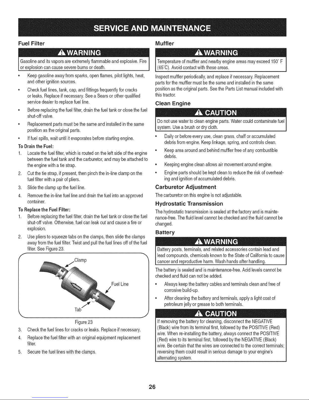
2. Useplierstosqueezetabsontheclamps,thenslidethe clamps
awayfromthefuel filter.Twistandpullthefuellinesoff ofthefuel
filter.SeeFigure23.
f
FuelLine
7
,,,..,., ,,J
Figure23
.
Checkthefuellinesforcracksor leaks.Replaceif necessary.
4.
Replacethe fuelfilterwithan originalequipmentreplacement
filter.
.
Securethefuellineswiththeclamps.
Temperatureofmufflerandnearbyengineareasmayexceed150°F
(65°0).Avoidcontactwiththeseareas.
Inspectmufflerperiodically,andreplaceifnecessary.Replacement
partsforthe mufflermustbethe sameand installedin thesame
positionasthe originalparts.SeethePartsListmanualincludedwith
thistractor.
Clean Engine
Donot usewatertoclean engineparts.Watercouldcontaminatefuel
system.Usea brushor dry cloth.
Dailyor beforeeveryuse,cleangrass,chaffor accumulated
debrisfromengine.Keeplinkage,spring,andcontrolsclean.
Keepareaaroundand behindmufflerfreeof anycombustible
debris.
Keepingenginecleanallowsair movementaroundengine.
• Enginepartsshouldbekeptcleanto reducetheriskof overheat-
ing andignitionofaccumulateddebris.
Carburetor Adjustment
Thecarburetoronthisengineis notadjustable.
Hydrostatic Transmission
Thehydrostatictransmissionis sealedatthefactoryandismainte-
nance-free.Thefluidlevelcannotbecheckedandthe fluidcannotbe
changed.
Battery
Batteryposts,terminals,and relatedaccessoriescontainleadand
leadcompounds,chemicalsknowntotheStateofCaliforniatocause
cancerand reproductiveharm.Washhandsafterhandling.
Thebatteryissealedandis maintenance-free.Acidlevelscannotbe
checkedandfluid cannotbe added.
Alwayskeepthebatterycablesandterminalscleanandfreeof
corrosivebuild-up.
• Aftercleaningthebatteryandterminals,applya lightcoatof
petroleumjelly orgreasetobothterminals.
Ifremovingthe batteryforcleaning,disconnecttheNEGATIVE
(Black)wirefromitsterminalfirst,followedby the POSITIVE(Red)
wire.Whenre-installingthebattery,alwaysconnectthe POSITIVE
(Red)wire toits terminalfirst,followedbythe NEGATIVE(Black)
wire.Becertainthatthewiresareconnectedto thecorrectterminals;
reversingthemcouldresultinseriousdamagetoyourengine's
alternatingsystem.
26
Page 27
CLEANING THE TRACTOR
Anyfuel oroil spilledonthe machineshouldbewipedoffpromptly.Do
NOTallowdebristoaccumulatearoundthecoolingfinsof the engine,
thetransmission'scoolingfanor onany otherpartof themachine,
especiallythebeltsandpulleys.
Deck Wash System
Yourtractor'sdeckisequippedwitha waterportonits surfaceaspart
ofits deckwashsystem.
Usethedeckwashtorinsegrassclippingsfromthedeck'sunderside
andpreventthe buildupofcorrosivechemicals.Completethefollowing
stepsAFTEREACHMOWING:
1. Drivethetractorto a level,clearspotonyour lawn,nearenough
foryourgardenhoseto reach.
Makecertainthetractor'sdischargechuteis directedAWAYfromyour
house,garage,parkedcars,etc.
2. DisengagethePTO(BladeEngage),settheparkingbrakeand
stoptheengine.
3. Threadthehosecoupler(packagedwithyourtractor'sOperator's
Manual)ontotheendof yourgardenhose.
4. Attachthe hosecouplertothewaterport onyourdeckssurface.
SeeFigure24.
11. Turnthewateroffanddetachthehose couplerfromthewater
portonyour deck'ssurface.
Aftercleaningyourdeck,returntothe operator'spositionandengage
thePTO.Keepthecuttingdeckrunningfora minimumoftwo minutes,
allowingtheundersideofthecuttingdecktothoroughlydry.
LUBRICATION
Beforelubricating,repairing,orinspecting,alwaysdisengagePTO,
set parkingbrake,stopengineandremovekeytopreventunintended
starting.
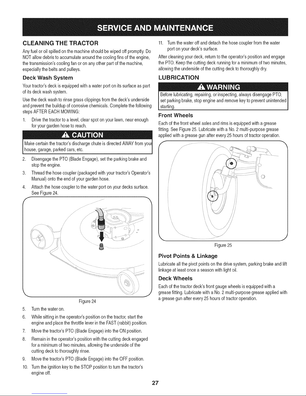
Front Wheels
Eachof thefrontwheelaxlesandrimsis equippedwitha grease
fitting.SeeFigure25.Lubricatewitha No.2 multi-purposegrease
appliedwitha greasegunafterevery25 hoursof tractoroperation.
Figure24
5. Turnthewateron.
6. Whilesittingin theoperator'spositiononthetractor,startthe
engineandplacethe throttleleverinthe FAST(rabbit)position.
7. Movethetractor'sPTO(BladeEngage)intotheONposition.
8. Remainintheoperator'spositionwiththecuttingdeckengaged
fora minimumoftwo minutes,allowingthe undersideof the
cuttingdeckto thoroughlyrinse.
9. Movethetractor'sPTO(BladeEngage)intotheOFFposition.
10. Turntheignitionkeyto the STOPpositiontoturnthetractor's
engineoff.
\
Figure25
Pivot Points & Linkage
Lubricateallthe pivotpointsonthe drivesystem,parkingbrakeandlift
linkageatleastoncea seasonwithlightoil.
Deck Wheels
Eachof thetractordeck'sfrontgaugewheelsisequippedwitha
greasefitting.Lubricatewitha No.2 multi-purposegreaseappliedwith
a greasegunafterevery25 hoursoftractoroperation.
27
Page 28
ADJUSTMENTS
Shutthe engineoff,removetheignitionkeyandengagetheparking
brakebeforemakingadjustments.Protectyourhandsbyusingheavy
gloveswhenhandlingtheblades.
NOTE:Checkthetractor'stirepressurebeforeperforminganydeck
levelingadjustments.RefertoTireson page24forinformationregard-
ingtirepressure.
Leveling the Deck (Front To Rear)
Thefrontof thecuttingdeckissupportedbya stabilizerbarthatcan
beadjustedtolevelthedeckfromfronttorear.Thefrontofthedeck
shouldbebetween1/4-inchand3/8-inchlowerthanthe rearof the
deck.Adjustif necessaryasfollows:
1. Parkthe tractorparkedona firm,level surfaceandplacethe deck
lift leverinthemiddleposition.
2. Rotatethebladenearestthedischargechutecoverso thatit is
parallelwiththetractor.
3. Measurethedistancefromthefrontof the bladetip totheground
andtherearofthe bladetiptotheground.Thefirstmeasurement
takenshouldbebetween1/4"and 3/8"lessthanthesecond
measurement.
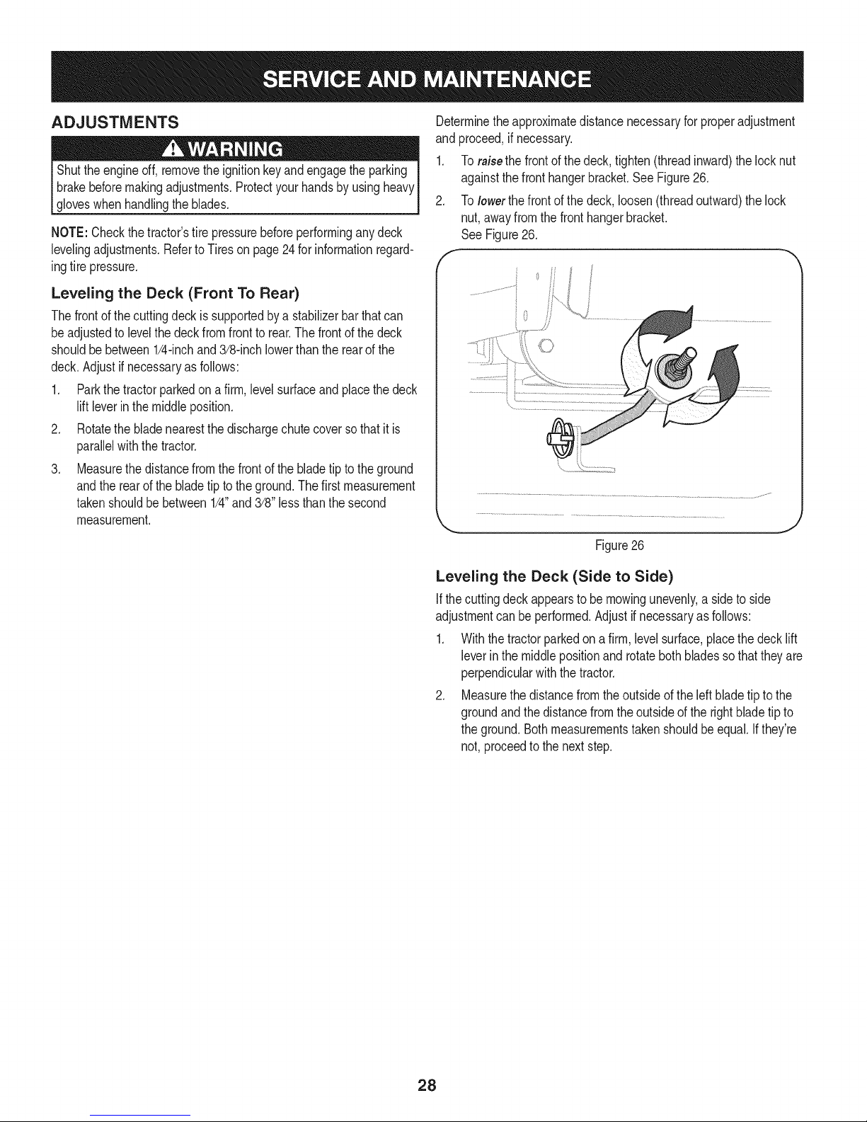
Determinetheapproximatedistancenecessaryfor properadjustment
and proceed,if necessary.
1. Toraisethefrontofthedeck,tighten(threadinward)thelocknut
againstthefronthangerbracket.SeeFigure26.
2. Tolowerthefrontofthedeck,loosen(threadoutward)thelock
nut,awayfromthefronthangerbracket.
See Figure26.
f
J
Figure26
Leveling the Deck (Side to Side)
Ifthecuttingdeckappearstobe mowingunevenly,a sideto side
adjustmentcan beperformed.Adjustifnecessaryasfollows:
1. Withthetractorparkedona firm, levelsurface,placethedecklift
leverin themiddlepositionandrotatebothbladessothattheyare
perpendicularwiththetractor.
2. Measurethedistancefromthe outsideoftheleft bladetiptothe
groundandthedistancefromtheoutsideofthe rightbladetipto
theground.Bothmeasurementstakenshouldbeequal.Ifthey're
not, proceedto the nextstep.
28
Page 29
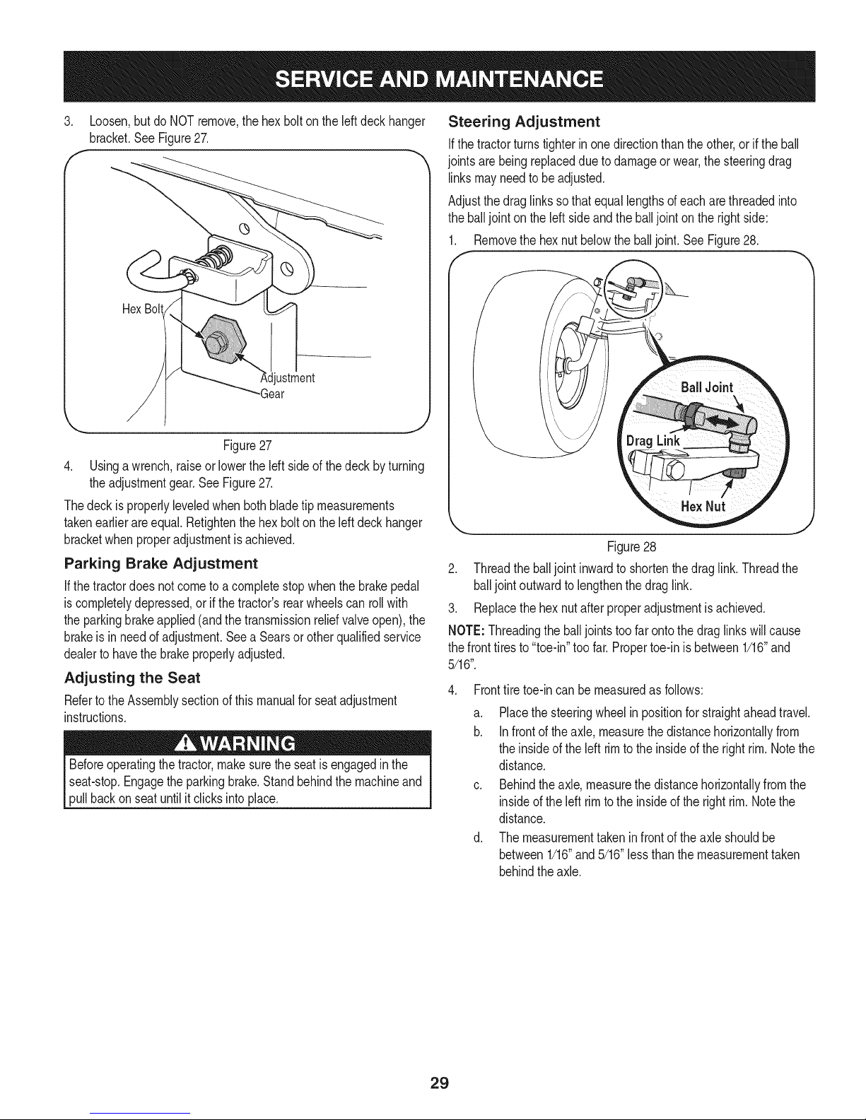
3. Loosen,butdo NOTremove,thehexboltontheleftdeck hanger
bracket.SeeFigure27.
f
Hex Bolt
ustment
-Gear
Figure27
4. Usinga wrench,raiseorlowertheIdt side of thedeckbyturning
theadjustmentgear.SeeFigure27.
Thedeckis properlyleveledwhenbothbladetipmeasurements
takenearlierareequal.Retightenthe hexboltonthe leftdeckhanger
bracketwhenproperadjustmentis achieved.
Parking Brake Adjustment
If thetractordoesnotcometoacompletestopwhenthe brakepedal
iscompletelydepressed,or ifthe tractor'srearwheelscan rollwith
theparkingbrakeapplied(andthe transmissionreliefvalveopen),the
brakeis in needofadjustment.Seea Searsorotherqualifiedservice
dealertohavethebrakeproperlyadjusted.
Adjusting the Seat
Refertothe Assemblysectionofthismanualforseatadjustment
instructions.
Beforeoperatingthe tractor,makesuretheseatis engagedinthe
seat-stop.Engagetheparkingbrake.Standbehindthe machineand
pullbackonseatuntilit clicksinto place.
Steering Adjustment
Ifthetractorturnstighterinonedirectionthantheother,or ifthe ball
jointsarebeingreplaceddue to damageorwear,thesteeringdrag
linksmayneedto beadjusted.
Adjustthedraglinksso thatequallengthsofeacharethreadedinto
theballjoint onthe left sideandthe balljointon the rightside:
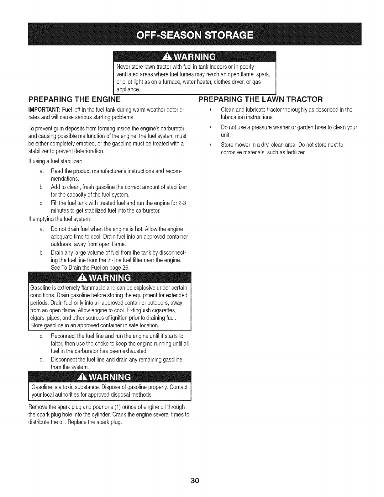
1. Removethehexnut belowtheballjoint. SeeFigure28.
J
Figure28
2. Threadthe balljoint inwardto shortenthedraglink.Threadthe
balljointoutwardto lengthenthedraglink.
3. Replacethehexnut afterproperadjustmentisachieved.
NOTE:Threadingthe balljointstoofarontothedraglinkswillcause
thefronttiresto"toe-in"too far.Propertoe-inis between1/16"and
5/16".
4. Fronttiretoe-incan be measuredasfollows:
a. Placethesteeringwheelinpositionforstraightaheadtravel.
b. Infrontofthe axle,measurethedistancehorizontallyfrom
theinsideoftheleft rimto the insideoftherightrim.Notethe
distance.
c. Behindthe axle,measurethedistancehorizontallyfromthe
insideoftheleft rimtothe insideofthe rightrim.Notethe
distance.
d. Themeasurementtakeninfrontoftheaxleshouldbe
between1/16"and5/16"lessthanthemeasurementtaken
behindthe axle.
29
Page 30
Neverstorelawntractorwithfuelin tankindoorsorin poorly
ventilatedareaswherefuelfumesmayreachan openflame,spark,
or pilotlightasona furnace,waterheater,clothesdryer,or gas
appliance,
PREPARING THE ENGINE
IMPORTANT:Fuelleftin thefueltankduringwarmweatherdeterio-
ratesandwillcauseseriousstartingproblems.
Topreventgumdepositsfromforminginsidetheengine'scarburetor
andcausingpossiblemalfunctionoftheengine,thefuelsystemmust
beeithercompletelyemptied,or thegasolinemustbetreatedwitha
stabilizerto preventdeterioration.
If usingafuelstabilizer:
a. Readthe productmanufacturer'sinstructionsand recom-
mendations.
b. Addtoclean,freshgasolinethecorrectamountofstabilizer
forthecapacityofthe fuel system.
c. Fillthefueltankwithtreatedfueland runtheenginefor2-3
minutestogetstabilizedfuel intothecarburetor.
If emptyingthefuelsystem:
a. Donotdrainfuel whentheengineis hot.Allowtheengine
adequatetimetocool. Drainfuelintoanapprovedcontainer
outdoors,awayfromopenflame.
b. Drainanylargevolumeoffuelfromthetankby disconnect-
ingthefuel linefromthe in-linefuelfilterneartheengine.
SeeToDraintheFuelonpage26.
PREPARING THE LAWN TRACTOR
• Cleanandlubricatetractorthoroughlyasdescribedinthe
lubricationinstructions.
• Do notusea pressurewasherorgardenhoseto cleanyour
unit.
• Storemowerina dry,cleanarea.Do not storenextto
corrosivematerials,suchasfertilizer.
Gasolineisextremelyflammableandcanbeexplosiveundercertain
conditions.Draingasolinebeforestoringtheequipmentforextended
periods.Drainfuelonlyintoan approvedcontaineroutdoors,away
fromanopenflame.Allowenginetocool.Extinguishcigarettes,
cigars,pipes,andother sourcesofignitionpriortodrainingfuel.
Storegasolinein anapprovedcontainerin safelocation.
c. Reconnectthe fuellineand runtheengineuntilit startsto
falter,thenusethe choketokeeptheenginerunninguntilall
fuelin thecarburetorhasbeenexhausted.
d. Disconnectthefuellineanddrainanyremaininggasoline
fromthesystem.
Gasolineisa toxicsubstance.Disposeof gasolineproperly.Contact
yourlocal authoritiesforapproveddisposalmethods.
Removethesparkplugandpourone(1)ounceofengineoilthrough
thesparkplugholeintothecylinder.Cranktheengineseveraltimesto
distributetheoil. Replacethe sparkplug.
30
Page 31

Beforeperforminganytypeof maintenance/service,disengageall
controlsandstoptheengine.Waituntilallmovingpartshavecometo
a completestop.Disconnectsparkplugwireandgrounditagainstthe
engineto preventunintendedstarting.Alwayswearsafetyglassesduring
operationorwhileperforminganyadjustmentsorrepairs.
Thissectionaddressesminorserviceissues.Tolocate the nearestSears Service Centeror to scheduleservice,simplycontactSears
at 1-800-4-MY-HOME®.
Enginefailstostart
1. PTO/BladeEngageknobengaged.
2. Parkingbrakenotengaged.
3. Sparkplugwire disconnected.
4. Throttle/Chokecontrollevernotincorrect
1. Placeknobindisengaged(OFF)position.
2. Engageparkingbrake.
3. Connectwiretosparkplug.
4. PlaceThrottle/ChokelevertoFASTposition.
startingposition.
5. Fueltankempty,or stalefuel.
6. BIockedfuelline.
5. Filltankwithclean,fresh(lessthan30daysold)gas.
6. Replacefuelline.Seea Searsorotherqualified
servicedealer.Replacefuel filter.SeetheService
andMaintenancesection.
Enginerunserratically
7. Faultysparkplug.
8. Engineflooded.
9. Fuse(s)blown.
1. Tractorrunningwith Chokeactivated.
7. Clean,adjustgapor replaceplug.
8. CrankenginewiththrottleinFASTposition.
9. Replacefuse.
1. MovetheThrottle/Chokecontrolleveroutofthe
chokeposition.
2. Sparkplugwiresloose.
3. Blockedfuellineor stalefuel.
2. Connectandtightensparkplugwires.
3. Replacefuelline.Seea Searsorotherqualified
servicedealer.Filltankwithclean,freshgasoline
andreplacefuelfilter.Seethe Serviceand Mainte-
nancesection.
4. Ventingascap plugged.
5. Waterordirtin fuelsystem.
4. Clearventor replacecapifdamaged.
5. Drainfueltank.Refillwithclean,freshgasoline.See
theServiceand Maintenancesection.
6. 6.
Dirtyair cleaner.
Replaceair cleanerpaperelementorcleanfoam
precleaner.
Engineoverheats 1. Engineoillevellow 1.
2. Airflowrestricted 2.
Fillenginewith properamountandtype ofoil.
Cleangrassclippingsanddebrisfromaroundthe
engine'scoolingfinsandblowerhousing.
Enginehesitatesat high RPMs 1. Sparkpluggap settooclose 1. Remove
Engineidlespoorly 1. Fouledsparkplug 1. Replace
2. Dirtyaircleaner 2. Replace
sparkplugandadjustgap.
sparkplugandadjustgap.
air cleanerelementand/orcleanpre-
cleaner.
Excessivevibration 1. Cuttingbladeslooseor unbalanced 1. Tightenbladeandspindle.Balanceblade.
2. Damaged,dull,orbentcuttingblade 2. Replaceblade.
31
Page 32

Mowerwill notmulchgrass
Unevencut
1. Enginespeedtoolow.
2. Wetgrass.
3. Excessivelyhighgrass.
4. Dullblade.
1. Decknotleveledproperly.
2. Dullblade.
3. Uneventirepressure.
o Find information and tools to help with home projects.
1. PlaceThrottle/Chokecontrolin FAST(rabbit)
position.
2. Donotmulchwhengrassiswet.
3. Mowonceata highcuttingheight,then mowagain
atdesiredheightor makea narrowercuttingswath.
4. Sharpenorreplaceblade.
1. Performside-to-sidedeckadjustment.
2. Sharpenorreplaceblade.
3. Checktirepressureinallfourtires.
32
Page 33

Congratulationson makingasmartpurchase.YournewCraftsman@
productisdesignedandmanufacturedforyearsofdependableopera-
tion.Butlikeall products,itmayrequirerepairfromtimetotime.That's
whenhavinga RepairProtectionAgreementcansaveyoumoneyand
aggravation.
Here'swhattheRepairProtectionAgreement*includes:
* Expert service byour10,000professionalrepairspecialists
o Unlimitedserviceand no chargeforpartsand laboron all
coveredrepairs
o Product replacementupto$1500if yourcoveredproductcan'tbe
fixed
• Discountof 10%fromregularprice ofserviceandrelatedinstalled
partsnotcoveredby theagreement;also,10%off regularpriceof
preventivemaintenancecheck
• Fasthelp byphone- wecall it RapidResolution- phonesupport
froma Searsrepresentative.Thinkof usasa "talkingowner's
manual."
Onceyoupurchasethe Agreement,a simplephonecallis all thatit
takesfor youto scheduleservice.Youcan callanytimedayor night,or
schedulea serviceappointmentonline.
TheRepairProtectionAgreementisa risk-freepurchase.Ifyoucancel
forany reasonduringtheproductwarrantyperiod,wewillprovideafull
refund.Or,a proratedrefundanytimeafterthe productwarrantyperiod
expires.PurchaseyourRepairProtectionAgreementtoday!
Somelimitationsandexclusionsapply. Forpricesand additional
informationin the U.S.A.call 1-800-827-6655.
*CoverageinCanadavaries on some items.Forfull details call
SearsCanadaat 1-800-361-6665.
SearsInstallation Service
ForSearsprofessionalinstallationofhomeappliances,garagedoor
openers,waterheaters,andothermajorhomeitems,in theU.S.A.or
Canadacall1-800-4-MY-HOME®.
33
Page 34

Steering and Axle B IViodel No. 247.28888
36"%3
.... ..35
34
4
9
31
3205-"_.31
28
34
Page 35

Steering and Axle B Model No. 247.28888
710-04095 HexHeadScrew,3/8-16:1.00 638-04022-0637 RHAxleAssembly
2 710-0514 HexHeadScrew,3/8-16:1.00 i21 638-04028-0637 LHAxleAssembly
3 710-0643 HexHeadScrew,5/16-18:1.00 22 i710-0395 HexHeadScrew,5/16-18:2.25
4 711-04998 iLHDragLink 23 710-0859 HexHeadScrew,3/8-16:2.50
5 711-04999 iRH DragLink 24 710-3180 HexHeadScrew,5/16-18:1.75
6 912-0240 iJamNut,7/16-20 25 912-0214 HexlockNut,3/8-24
7 712-04065 iFlangelockNut,3/8-16 26 712-04063 FlangelockNut,5/16-18
8 712-0459 iFlangelockNut,7/16-20 27 714-0162 CotterPin,5/32:1.25
9 712-3004A iFlangelockNut,5/16-18 28 719-04413A PivotBarAxle
10 717-1550F iSteeringGear 29 934-0255 TubelessAirValve
11 717-1554 iSteeringPinionGear 30 748-04065-0637 SteeringBlock
12 923-0448A iBallJoint,7/16-20 31 748-04068 Spacer,.71IDX .125ODX .56LG
13 936-3004 FlatWasher,.406X .875X.105 32 750-05280 Spacer,.385X 1.00X1.5075
14 736-3084 FlatWasher,.51X 1.12X .06:HT 33 731-05674 BumperCap
15 634-04405-4042 RimAssembly 34 736-04228A FlatWasher,.7811Dx1.5900D
16 738-04263 iSteeringShaft,.625ODX24.25LG 35 631-04415 SteeringWheel
17 738-04363 ShoulderSpacer,.385X1.25X .3025 i36 731-06825 SteeringWheelCap
18 741-04237B iHexFlangeBearing5/8 PM 37 i634-04406-0961 WheelAssembly
19 783-06043-0637 ISteeringSupportBracket i38 734-1731-0901 Tire
35
Page 36

Hood and Dash B IViodel No. 247.28888
3o
31
21
13
9_I 8
29,
15
36
Page 37

Hood and Dash B Model No. 247.28888
631-04353A DashLever 710-05108 Screw,LockWasher,1/4DIA:.750
2 710-04484 TaptiteScrew,LockWasher,5/16-18:.750 i25 931-07457 Grill
3 710-0599 TaptiteScrew,LockWasher,1/4-20:0.500 i26 731-07458 RHLens
4 710-0895 Hi-LoScrew,LockWasher,1/4-15:0.750 i27 731-07459 LHLens
5 710-1652 Screw,LockWasher,1/4-20:0.625 i28 931-07461 HoodScoop
6 710-1017 Screw,1/4-14:0.625 i29 731-07467 LowerGrill
7 710-1611B TaptiteScrew,5/16-18:0.750 i30 731-07469 LHHoodScoop
8 710-3217 MachineScrew,#8-32:0.375 i31 731-07470 RHHoodScoop
9 712-0142 HexNut,#8-32:GRA i32 738-04091A ShoulderScrew,.43X.29:TT:5/16-18
10 714-04040 Bow-tieCotterPin i33 710-0642 TaptiteScrew,1/4-20:0.750
11 726-3046 RatchetClip:.250DIA i34 747-05049 RHTankSupportRod
12 731-07456 Dash i35 747-05050 LHTankSupportRod
13 731-07550 ControlKnob i36 751-0603A FuelCap
14 732-04580 ExtensionSpring,.500DIAX 2.733LG i37 951-10573 FuelTank,2.75Gallons
15 735-0271A Bumper i38 946-04621 Throttle/ChokeControl
16 735-04076 AccessoryNet i39 735-04170 FuelTankGasket
17 747-05280 ControlRodLatch i40 731-07495 P-StylePlen
18 747-1196 LeverRod i41 925-0963 MiniatureLamp,12V
19 783-04285F-0637RHDashSupportPlate 42 925-1649 LampSocket
20 783-04323F-0637LHDashSupportPlate i43 725-04992 SwitchKeyModule
21 625-04124 Keys(Setof2) i44 925-040360 HourMeter
22 683-04618-0691 HoodAssembly i45 725-04258 PTOSwitch
23 710-04187 Hi-loScrew,LockWasher,1/4-15:0.50
37
Page 38

Seat and Fender B IViodel No. 247.28888
24
38
3O
32
36
34
38
Page 39

Seat and Fender B Model No. 247.28888
683-04223-0637 LiftShaftAssembly 732-04563 CompressionSpring,.68X 1.065X.055
2 712-04063 FlangelockNut,5/16-18 i23 938-0296 ShoulderScrew,.437X .268:5/16-18
3 712-04065 FlangelockNut,3/8-16 i24 783-06049-0691 SeatMountingBracket
4 914-0104 CotterPin,.072DIA.X 1.13LG i25 783-06050 SeatAdjustmentLever
5 714-04040 Bow-TieCotterPin i26 783-06088-0691 SeatPivotBracket
6 716-0106A E-Ring,.625DIA.SHAFT i27 783-06448 SwitchRetainerClip
7 720-04150 HandleGrip i28 710-04187 Hi-LoScrew,LockWasher,1/4-15:0.50
8 732-0874 TorsionSpring i29 710-0451 CarriageBolt,5/16-18:.750
9 736-0105 SpringWasher,.401X .870X.063 i30 710-0599 TaptiteScrew,LockWasher,1/4-20:0.500
10 738-0138A ShoulderScrew, .437X .470:5/16-18 i31 710-0895 Hi-LoScrew,LockWasher,1/4-15:0.750
11 938-0380 ShoulderBolt,.500X.270:3/8-16 i32 731-05837 LH FenderCover
12 941-0225 HexFlangeBearing i33 731-06754 RHFenderCover
13 746-0968 LiftCable,16.16LG i34 736-3078 FlatWasher,.344X 1.00X .063HDN
14 747-04962A Lift Handle i35 783-06118-0691 Fender
15 756-04331 PulleyRollerCable i36 726-3046 RatchetClip
16 783-05546A-0637LiftArm i37 735-04137 LHFootPad
17 710-04482 HexHeadFlange,3/8-16:.875 -- 735-04139 RHFootPad
18 710-04484 TaptiteScrew,LockWasher,5/16-18:.750 i38 757-04127 Seat
19 712-3004A FlangelockNut,5/16-18 i39 783-06181-0637 LiftBracket
20 725-0157 CableTie,3/16X .05X 7.4 i40 925-05013 Seat Switch
21 732-04561 CompressionSpring,1.71X3.735X.238
3g
Page 40

Drive and Rear Wheels B IViodel No. 247.28888
2O
37 20
A
14
72
5
55
51
58
67
57 56
/
61
4O
Page 41

Drive and Rear Wheels B Model No. 247.28888
918-0319
2
710-0176
3
710-0227
4
710-0351
5
710-04484
6
710-0653
7
710-1007
8
710-1325
9
710-3011
10
912-0240
11
912-0346
12
712-04063
13
912-0431
14
914-0111
15
725-0157
16
725-04791A
17
725-1644
18
926-0154
19
926-0320
2O
731-05299A
21
731-06098
22
932-0209
23
732-04606
24
732-04792 ExtensionSpring,1.00DIAX 4.75
25
732-0716D ExtensionSpring,.59ODX 4.00LG
26
732-0729 iWireRing
27
732-3118 ExtensionSpring,.375ODX 1.44LG
28
936-0264
29
736-04263
30
936-3008
31
736-3010
32
934-0255
33
734-1730-0901
34
738-04420
35
747-04139
36
747-04957A
37
747-04979
38
747-04991
39
750-04456
HydroTransmission
HexHeadScrew,5/16-18:2.75
iScrew,IndentedWasher,#8-18:0.500
iScrew,#10-16:0.500
TaptiteScrew,IndentedWasher,5/16-18:.750
TaptiteScrew,IndentedWasher,1/4-20:0.375
TaptiteSeresScrew,:3/8-16:1.500
TaptiteScrew,IndentedWasher,1/4-20:1.625
HexHeadScrew,3/8-16:2.25
iJamNut,7/16-20
JamlockNut,1/2-20
iFlangelockNut,5/16-18
iFbngelockNut,3/8-16
iCotterPin,3/32:1.0
CableTie.3/16X .05X 7.4
iJumperHarness
iShortSpringSwitch
PushMountCableTie7.5LG
InsulatorNutPlate
iSleeve,.765IDX 1.500LG
HydroFan
ExtensionSpring,.48ODX 2.03
ExtensionSpring,.500DIAX 12.6LG
FlatWasher,.330X .630X .0635
LockWasher
FlatWasher,.344X .750X.120
FiatWasher,.407X .812X .135
TubelessAirValve
Tire
ShoulderSpacer,1.375X .380X.183
BrakeRod
iFootpedalBypassTransmissionRod
HydroControlRod
HydroBypassRod
Spacer,260X .372X1.420LG
954-04207 V-Belt,4L X 78.9POLY
i41 756-04224 FlatIdlerPulley,2.75OD
i42 756-04308 InputPulley,4.13DIA
i43 756-04325 V IdlerPulley,X3.06
i44 783-06027A CenterldlerBracket
i45 783-06133-0637 HydroMountingBracket
i46 783-06260-0637 BeltDisengageSupportBracket
i47 783-1019B SwitchActuatorBracket
i48 647-04152B BrakeControlAssembly
i49 683-04488 HydroPedalBracketAssembly
i50 710-0604A TaptiteScrew,IndentedWasher,5/16-18:0.625
i51 711-05068 ClevisPin,5/16X3.985
i52 712-04065 FlangelockNut,3/8-16
i53 714-04040 Bow-TieCotterPin
i54 726-0214 PushCap
i55 732-04587 ExtensionSpring,.63DIAX 4.95LG
i56 735-04118A ForwardPedalPad
i57 735-04135 ReversePedalPad
i58 735-04136 BrakePedalPad
i59 736-0242 BellWasher,.340X .872X .060
i60 634-04369-4042 RimAssembly
i61 938-0380 ShoulderBolt,.500X .270:3/8-16
62 741-0495 FlangeBearing,.630IDX.695OD X .60
i63 748-04203 CruiseLatch
i64 783-05914 PedalSupportBracket
i65 783-05940 PedalSupportBracket,5/8
i66 783-06059-0637 DrivePedalBracket
67 783-06103A-0637BrakePedalBracket
i68 634-0104-0961 WheelAssembly
i69 710-0627 HexHeadScrew,5/16-24:.750
i70 736-0430 FiatWasher,.350x 1.59x .062
i71 731-2290A HubCap
i72 747-05444 BeltKeeperRod
i73 712-04065 FlangelockNut,3/8-16
74 738-0430 ShoulderScrew,.50x .685:3/8-16
i75 750-0566A Spacer,260X .375X 1.030LG
i76 710-0809 TaptiteScrew,IndentedWasher,1/4-20:0.375
i77 936-0344 FlatWasher,.385X 1.00X .030
41
Page 42

Engine Accessories B IViodel No. 247.28888
11
...... 13
42
Page 43

Engine Accessories B IViodel No. 247.28888
683-04549-0637 MulfflerShieldAssembly
2 710-0227 Screw,IndentedWasher,#8-18:0.500
3 710-04683 TaptiteScrew,indentedWasher,3/8-16:1.000
4 710-0599 TaptiteScrew,indentedWasher,1/4-20:0.500
5 710-1314A SocketHeadScrew,5/16-18:.750
6 712-0271 SeresNut,1/4-20
7 783-06378A HeatShield
8 721-0460 ExhaustGasket
9 725-0157 CableTie,3/16X .05X 7.4
10 726-0205 HoseClamp,.490DIA.
11 751-11053 LongMufflerDeflector
12 751-10349 FuelHose
13 751-10542A Muffler
14 44P777-2799-G1 ReplacementEngine
43
Page 44

PTO and Battery B IViodel No. 247.28888
17 _o =o_115i 19
i
20
13
12
i
13/_
44
Page 45

PTO and Battery B IViodel No. 247.28888
683-04469B-0691
2 710-04484
3 710-0653
4 710-3005
5 712-04065
6 738-04058
7 747-04121A
8 783-0349-0637
9 783-06089-0637
10 710-04379A
11 91_04552
12 725-0157
13 936-0171
14 736-0277
15 712-0271
16 756-0978B
17 710-04666
18 747-05171
19 725-05088
20 725-04439
21 712-04064
22 725-04363
23 738-04237A
24 732-0814
NS 925-04093
Frame
TaptiteScrew,indentedWasher,5/16-18:.750
TaptiteScrew,indentedWasher,1/4-20:0.375
HexHeadScrew,3/8-16:1.25
FlangelockNut,3/8-16
ShoulderSpacer,.38X 1.0X .70
BatteryHolderRod
BatteryTray
SeatFrameBracket
HexHeadScrew,7/16-20:3.50
ElectricPTOClutch
CableTie,3/16x .05x7.4
LockWasher,7/16
FiatWasher,1.031x 1.620x .095
SeresNut,1/4-20
ElectricPTOEnginePulley
HexHeadFlange,1/4-20:.75
BeltGuard
Battery
Solenoid,12V
FlangelockNut,1/4-20
interlockSwitch
ShoulderScrew,#10-32:.500
ExtensionSpring,.56 Od.x5.52 Lg.
WireHarnessAssembly
45
Page 46

Deck B IViodel No. 247.28888
55_t_40
53,._
22
_36
39 11_
43\_-_ ! _19
2
11
46
Page 47

Deck B Model No. 247.28888
918-04636A SpindleAssembly
2 683-0254B-4028 DeckHangerBracketAssembly
3 983-04468A-4028DeckAssembly
4 710-04484 TaptiteScrew,indentedWasher,5/16-18:.750
5 710-0514 HexHeadScrew,3/8-16:1.00
6 710-0528 HexHeadScrew,5/16-18:1.25
7 710-0599 TaptiteScrew,indentedWasher,1/4-20:0.500
8 710-3144 HexHeadScrew,3/8-16:2.00
9 710-3178 CarriageBolt,3/8-16:0.75
10 712-0229 PushNut,3/8
11 712-04065 FlangelockNut,3/8-16
12 712-0417A FlangeNut,5/8-18
13 712-04243 LockNut,1/2-13
14 912-0641 HexNut,M16-1.5DIN936
15 753-04070 LynchPin,.1875
16 914-0470 CotterPin,1/8X 1.25
17 917-04074 DeckGear
18 921-04041 WaterNozzleAdaptor
19 732-0459C ExtensionSpring,.94DIA.X 6.74LG
20 732-04652 CompressionSpring,.535ODX 1.751LG
21 734-04155 FrontDeckWheel
22 734-0973 RearDeckWheel
23 936-0119 LockWasher,5/16
24 936-0179 FiatWasher,.531X 1.25X .100
25 736-0225 LockWasher,5/8
26 736-0258 FiatWasher,.385X 1.0X .135
27 736-0262 FiatWasher,.385X .870X .092
28 736-0317 BellWasher,.63X 1.25X .18
936-0344 FiatWasher,.385X 1.0X .030
30 737-04003D WaterNozzle
31 938-0373 ShoulderBolt,.496X1.525:3/8-16
i32 738-04162A ShoulderSpacer,.8840X .190
i33 938-3056 ShoulderBolt, .496X 2.50:3/8-16
i34 942-04244A 2-in-1CuttingBlade
i35 747-04944B DeckLiftRod
i36 756-04356 DeckPulley,6.93DIA
i37 747-1116 DeckReleaseHandleRod
i38 954-04219 V-Belt
i39 756-04129B IdlerPulley,4.25"DIA
i40 936-0351 FlatWasher,.760IDX1.50OD
i41 783-04740-0637 DeckEngageCableBracket
42 738-1186A SpindleShaft,6.05 LG.
43 783-05946 IdlerBracket
i44 783-06243-0637 DeckEngageCableBracket
i45 783-06368A-06374.25 PulleyBeltGuardBracket
i46 731-06496 BeltCover
i47 783-06632-4028 DeckStop
i48 783-06643-4028 DeckIdlerSupportBracket
i49 711-04847B HingePin
i50 732-04372 TorsionSpring
i51 783-06074A ChuteBracket
i52 631-04460 ChuteDeflector
i53 941-0919 BallBearing,.7871DX 1.850DX.551
i54 750-04936 Spacer,.792X 1.060X1.860LG
i55 750-0952 Spacer,.792X 1.060X1.800LG
47
Page 48

Craftsman Engine Model44P777-2799-G1ForModel247.28888
48 SHORT BLOCK 1058 OPERATOR'S MANUAL 1329 REPLACMENT ENGINE 1330 REPAIR MANUAL
lOl
u
850
9
252 250
i i i i ii
45
616
552A_
742_{_}}
404 :_
552_
691 _}
2O
615 ,o
1027
1013
512
1017
L
188 _............//
750 1i
48
Page 49

Craftsman Engine IViodel 44P777-2799-G1 For IViodel 247.28888
_'_ ..... I
24[_
163
741
49
Page 50

Craftsman Engine IViodel 44P777=2799=G1 For IVlodel 247.28888
635
13
1o22
36 _
1100
850
883
883
1o22
337
1022 _" '
914 _
50
Page 51

Craftsman Engine IViodel 44P777=2799=G1 For IViodel 247.28888
51A
i
51A
108' _,, '_ i i . i
[ 633 217
[illllillii ili,
i¼_i i L
i 276 _f i
150 ioi
183 ic;/_"s{J "'_s_"'_;i
i i i i
J
654
387
24O
51
Page 52

Craftsman Engine Model 44P777-2799=G1 For Model 247.28888
3O4
...........................................................................................................................................i
1040
1036 EMiSSiONS LABEL
306A K 306
703 t_ _* _(j_:,_,
_" 307 a
@
_186A %¢-%
964 '1¢ /-::::- : .........
445 ::::::::::::::::::::::::::
......................(_ ...........................................m_
/. .............................................\
967 ii
865
z!'
ii
447
573
52
Page 53

Craftsman Engine IViodel 44P777=2799=G1 For IViodel 247.28888
72_
211_:_
334
1070
1005
222
216
1119
789
695
526
367
729 _ .._:
801
501
1051 o
783
513
53
Page 54

Craftsman Engine Model 44P777-2799-G1 For Model 247.28888
121 CARBURETOR OVERHAUL KIT
51A
lO4 ,:::
........../ ..................s\
51A
105
7
51B
137
633 217
672
15O
163 987@
1124 d::":_)
276_4_!i_
358 ENGINE GASKET SET
163
1124A _/
524<_
691 ®
842 _\_
20
943<//_:)
94_A<_:p
868_ )
51A
1022
1095 VALVE GASKET SET
868_ )
883
1o22
/1
54
Page 55

Craftsman Engine IViodel 44P777=2799=G1 For IViodel 247.28888
|= e e
793564 CylinderAssembly
2 499585 Kit-Bushing/Seal(MagnetoSide)
3 391086s Seal-Oil(MagnetoSide)
4 796307 Sump-Engine
5 799088 Head-Cylinder(Cylinder#1)
73 494439 Screen-Rotating
74 698425 Screw(RotatingScreen)
75 691056 Washer(Flywheel)
95 690718 Screw(ThrottleValve)
5A 799089 Head-Cylinder(Cylinder#2) 98
7 693997 Gasket-CylinderHead 104
8 792185 BreatherAssembly 105
9 690937 Gasket-Breather 108
10 697551 Screw(BreatherAssembly) 117
11 792184 Tube-Breather
12 697227 Gasket-Crankcase
13 793988 Screw(CylinderHead)
15 690946 Plug-OilDrain
16 796540 Crankshaft
20 795387 Seal-Oil(PTOSide)
22 694966 Screw(CrankcaseCover/Sump)
23 691053 Flywheel
24 222698s Key-Flywheel
25 793560 PistonAssembly(Standard)
793563 PistonAssembly(.020"Oversize)
26 793561 RingSet(Standard)
792073 RingSet(.020"Oversize)
27 690975 Lock-PistonPin
28 696581 Pin-Piston
29 796209 Rod-Connecting
32 690976 Screw(ConnectingRod)
33 793357 Valve-Exhaust
34 793556 Valve-Intake
35 690963 Spring-Valve(Intake)
36 690963 Spring-Valve(Exhaust)
42 499586 Keeper-Valve
45 690977 Tappet-Valve
46 796853 Gear-Cam
48 797093 Short Block
50 695241 Manifold-Intake
51 795123 Gasket-Intake
51A 690950 Gasket-Intake
51B 690949 Gasket-Intake
53 690951 Stud(Carburetor)
118 791502 Jet-Main(HighAltitude)(LeftandRightJet)
121 792455 Kit-CarburetorOverhaul
125 796997 Carburetor
130 690993 Valve-Throttle
131 499805 Kit-ThrottleShaft
133 699724 Float-Carburetor
135 699729 Tube-FuelTransfer
137 690994 Gasket-FloatBowl
141 796228 Kit-ChokeShaft
142 699726 Nozzle-Carburetor
146 690979 Key-Timing
150 690995 Gasket-Nozzle
163 691001 Gasket-AirCleaner
165 693148 Nut (RingGear)
186 796532 Connector-Hose(Oil DrainHose)
186A 799158 Connector-Hose(EVAPSystem)
186B 795985 Connector-Hose(IntakeManifold)
187 791766 Line-Fuel(Cutto RequiredLength)
188 697551 Screw(ControlBracket)
192 690083 Adjuster-RockerArm
197 697820 Screw(Back Plate)
209 798921 Spring-Governor(Orange)
211 691019 Spring-GovernedIdle(NoColor)
212 695238 Link-Throttle
216 796229 Link-Choke
217 695409 Spring-ChokeReturn
219 793338 Gear-Governor
220 690412 Washer(GovernorGear)
221 841026 Cup-Governor
222 798915 Bracket-Control
D = 0 0
699816 Screw(IntakeManifold)
699721 Kit-IdleSpeed
694918 Pin-FloatHinge
797410 Valve-FloatNeedle
699723 Valve-Choke
842585 Jet-Main(Standard)(Leftand RightJet)
55
Page 56

Craftsman Engine IViodel 44P777=2799=G1 For IViodel 247.28888
D" 0 0
798856 Lever-GovernorControl
231 690718 Screw(ChokeValve)
240 695666 Filter-Fuel
250 690957 Retainer-Breather
252 794389 Collector-Oil
265 691024 Clamp-Casing
267 695134 Screw(CasingClamp)
276 695410 Washer-Sealing
278 792651 Washer(GovernorControlLever)
287 697551 Screw(DipstickTube)
304 797407 Housing-Blower
305 691005 Screw(BlowerHousing)
305A 790690 Screw(BlowerHousingto IntakeElbow)
306 798855 Shield-Cylinder(Cylinder#2)
306A 796852 Shield-Cylinder(Cylinder#1)
307 697551 Screw(CylinderShield)
524 691032 Seal-DipstickTube
525 691037 Tube-Dipstick
526 697551 Screw(Regulator)
552 796638 Bushing-GovernorCrank
552A 690553 Bushing-GovernorCrank
562 690311 Screw(GovernorControlLever)
573 790444 Plate-Back
579 691029 Nut (StarterCable)
601 691038 Clamp-Hose(Black)
615 698290 Retainer-GovernorShaft
616 691045 Crank-Governor
617 697891 Seal-ORing(IntakeManifold)(Red)
633 699813 Seal-Choke/ThrottleShaft(ChokeShaft)
634 698779 Spring/SealAssembly
635 66538s Boot-SparkPlug
309 795121 Motor-Starter 654
310 691263 Screw(StarterMotor) 668
332 691059 Nut(Flywheel) 668A
333 691060 Armature-Magneto 672
334 691061 Screw(MagnetoArmature) 691
337 491055s Plug-Spark
358 694012 GasketSet-Engine
367 697820 Screw(WireClip)
385 797409 Screw(Fuel Pump)
387 808656 Pump-Fuel
404 690442 Washer(GovernorCrank)
415 794903 Plug(Oil PressureSwitchHole)
418 795912 Plate-Carburetor
431 798860 Elbow-Intake
445 792105 Filter-AirCleanerCartridge
447 691003 Screw(Air GuideCover)
467 790697 Knob-AirCleaner
474 696458 Alternator
501 797375 Regulator
503 691532 Strap-Starter
505 691029 Nut(GovernorControlLever)
510 794360 Drive-Starter
512 796530 Hose-OilDrain
513 692024 Clutch-Drive
695 693149 Screw(RingGear)
697 690372 Screw(DriveCap)
703 691010 Clip
718 690959 Pin-Locating
726 499612 Gear-Ring
729 797454 Clip-Wire
741 690980 Gear-Timing
742 690328 Retainer-ERing(GovernorCrank)
750 796208 Screw(Oil PumpCover)
783 695708 Gear-Pinion
789 797424 Harness-Wiring
798 697890 Screw(RockerArm)
801 691283 Cap-Drive
802 691286 Cap-End
842 691031 Seal-ORing(DipstickTube)
847 499602 Dipstick/TubeAssembly
850 100106 Sealant-Liquid
851 493880s Terminal-SparkPlug
865 792286 Cover-AirGuide(Valley)
D = 0 O
691036 Dipstick
690958 Nut (Carburetor)
691215 Spacer(RotatingScreen)
691500 Spacer(RotatingScreen)
690234 Gasket-CarburetorPlate
790574 Seal-GovernorShaft
56
Page 57

Craftsman Engine IViodel 44P777=2799=G1 For IViodel 247.28888
690968 Seal-Valve
883 690970 Gasket-Exhaust
914 691127 Screw(RockerCover)
918 797408 Hose-Vacuum(RockerCover)
918A 799160 Hose-Vacuum(EVAPSystem)
929 695239 Screw(ChokeControlBracket)
943 796222 Seal-ORing (Oil PumpCover)
947 798779 Solenoid-Fuel
964 799159 Cap-Connector
965 796221 Cover-OilPump
967 792303 Filter-PreCleaner
968 795120 Cover-AirCleaner
975 798778 Bowl-Float
987 691000 Seal-ThrottleShaft
1005 791236 Fan-Flywheel
1013 690954 Nipple-OilFilter
1017 796214 Screen-OilPump
1022 690971 Gasket-RockerCover
1023 793146 Cover-Rocker(Cylinder#1)
1023A 499600 Cover-Rocker(Cylinder#2)
1024 796220 Pump-Oil
1026 690981 Rod-Push(Exhaust)(Steel)
1026A 690982 Rod-Push(Intake)(Aluminum)
1027 795890 Filter-Oil
1029 690972 Arm-Rocker
1036
Label-Emissions(Availablefroma Briggs
&StrattonAuthorizedDealer)
1040 791237 Plate-Trim
1051 691265 Ring-Retaining(StarterDrive)
1054 280275 Tie-Cable
1058 278776TRI Operator'sManual
1059 698516 Kit-Screw/Washer(Alternator)
1070 791680 Screw(FlywheelFan)
1090 691293 Retainer-Brush
1095 694013 GasketSet-Valve
1100 791959 Pivot-RockerArm
1119 691183 Screw(Alternator)
1124 841653 Seal-ORing (FuelTransferTube)
1124A 690988 Seal-ORing (FuelTransferTube)
1126 690991 Screw(FuelTransferTube)
1128 690990 Screw(CarburetorNozzle)
1169 690990 Screw(CarburetorPlate)
1329 2799-G1 ReplacementEngine
1330 273521 RepairManual
Key No. 358 EngineGasketSet
Key No. 1095 ValveGasketSet
Key No. 121 CarburetorOverhaulKit
D = 0 O
695407 Screw(FuelBowl)
44P777-
57
Page 58

777S33593
777D15597
O'1
777X44366
LEFT
777X44942
777S30018
777D15546
777X44365
RIGHT
777J23132
777D15594
777123092
777J23379
777D15584
777D15585
777S30503
777D15690
777123355
777X43688
B0._
USEE8_ORFUEL
C8_MM6 MO_
mAN1_, ETHANOL
777123357
777D15651
777D15650
777D15691
Page 59

Look For Relevant Emissions Durability Period and
Air index information On Your Engine Emissions Label
Engines that are certified to meet the California Air Resources Board (CARB) Tier 2 Emission Standards must
display information regarding the Emissions Durability Period and the Air Index. Sears Brands Management
Corporation makes this information available to the consumer on our emission labels.
The Emissions Durability Period describes the number of hours of actual running time for which the engine is
certified to be emissions compliant, assuming proper maintenance inaccordance with the Operating & Mainte-
nance Instructions. The following categories are used:
Moderate: Engine is certified to be emission compliant for 125 hours of actual engine running time.
Intermediate: Engine is certified to be emission compliant for 250 hours of actual engine running time.
Extended: Engine is certified to be emission compliant for 500 hours of actual engine running time.
For example, a typical walk-behind lawn mower is used 20 to 25 hours per year. Therefore, the Emissions
Durability Period of an engine with an intermediate rating would equate to 10 to 12 years.
The Air index is a calculated number describing the relative level of emissions for a specific engine family. The
lower the Air Index, the cleaner the engine. This information is displayed in graphical form on the emissions label.
After July 1,2000, Look For Emissions Compliance Period
On Engine Emissions Compliance Label
After July 1, 2000 certain Sears Brands Management Corporation engines will be certified to meet the United
States Environmental Protection Agency (USEPA) Phase 2 emission standards. For Phase 2 certified engines, the
Emissions Compliance Period referred to on the Emissions Compliance label indicates the number of operating
hours for which the engine has been shown to meet Federal emission requirements.
For engines less than 225 cc displacement, Category C = 125 hours, B = 250 hours and A = 500 hours.
For engines of 225 cc or more, Category C = 250 hours, B = 500 hours and A = 1000 hours.
This isa generic representation of the emission label typically found on a certified engine.
FAMILYYBSXS.3192VA 274812
GDOC-100182Rev.B
59
Page 60

(Thispageapplicableinthe U.S.A.andCanadaonly.)
Sears Brands Management Corporation (Sears), the California Air Resources Board (CARD)
and the United States Environmental Protection Agency (U.S. EPA)
Emission Control System Warranty Statement (Owner's Defect Warranty Rights and Obligations)
EMISSIONCONTROLWARRANTYCOVERAGEISAPPLICABLETOCERTI-
FIEDENGINESPURCHASEDINCALIFORNIAIN1995ANDTHEREAF-
TER,WHICHAREUSEDINCALIFORNIA,ANDTOCERTIFIEDMODEL
California and United States Emission
TheCaliforniaAirResourcesBoard(CARD),U.S.EPAandSearsare pleased
toexplainthe EmissionControlSystemWarrantyonyour modelyear2000and
latersmalloff-roadengine(SORE).InCalifornia,newsmalloff-roadengines
mustbe designed,builtandequippedto meettheState'sstringentanti-smog
standards.Elsewherein theUnitedStates,newnon-road,spark-ignition
enginescertifiedformodelyear1997and latermustmeetsimilarstandardsset
forthbythe U.S.EPA.Sears mustwarranttheemissioncontrolsystemonyour
YEAR1997ANDLATERENGINESWHICHAREPURCHASEDANDUSED
ELSEWHEREINTHEUNITEDSTATES(ANDAFTERJANUARY1,2001 IN
CANADA).
Control Defects Warranty Statement
enginefortheperiodsoftime listedbelow,providedtherehas beennoabuse,
neglector impropermaintenanceofyour smalloff-roadengine.Youremis-
sioncontrolsystemincludespartssuchas thecarburetor,air cleaner,ignition
system,mufflerandcatalyticconverter.Also includedmaybeconnectorsand
otheremissionrelatedassemblies.Whereawarrantableconditionexists,Sears
will repairyoursmalloff-roadengineatnocostto youincludingdiagnosis,parts
andlabor.
Sears Emission Control Defects Warranty Coverage
Smalloff-roadenginesarewarrantedrelativeto emissioncontrolpartsdefects
fora periodof one year,subjectto provisionssetforthbelow.Ifanycovered
Owner's Warranty
Asthe smalloff-roadengineowner,youareresponsiblefor theperformanceof
therequiredmaintenancelistedinyourOperatingand MaintenanceInstruc-
tions.Searsrecommendsthatyouretainallyourreceiptscoveringmaintenance
onyoursmalloff-roadengine,butSearscannotdenywarrantysolelyfor the
lackofreceiptsorfor yourfailuretoensuretheperformanceof allscheduled
maintenance.As the smalloff-roadengineowner,youshouldhoweverbe
awarethatSearsmaydenyyouwarrantycoverageifyour smalloff-roadengine
ora parthasfaileddueto abuse,neglect,impropermaintenanceor unap-
parton yourengineis defective,the partwillbe repairedorreplacedbySears.
Responsibilities
provedmodifications.Youareresponsiblefor presentingyour smalloff-road
engineto an AuthorizedSearsServiceDealeras soonasa problemexists.The
undisputedwarrantyrepairsshouldbecompletedinareasonableamountof
time,notto exceed30days.Ifyouhaveanyquestionsregardingyourwarranty
rightsandresponsibilities,youshouldcontacta SearsService Representative
at 1-800-469-4663.Theemissionwarrantyis a defectswarranty.Defectsare
judgedonnormalengineperformance.Thewarrantyis notrelatedtoan in-use
emissiontest.
Sears Emission Control Defects Warranty Provisions
ThefollowingarespecificprovisionsrelativetoyourEmissionControlDefectsWarrantyCoverage.ItisinadditiontotheSearsenginewarrantyfornon-regulated
enginesfoundin theOperatingand MaintenanceInstructions.
1. WarrantedParts
Coverageunderthis warrantyextendsonlytothe partslistedbelow(the
emissioncontrolsystemsparts)tothe extentthese partswere presenton
the enginepurchased.
a. FuelMeteringSystem
• Cold start enrichmentsystem
• Carburetorand internalparts
• FuelPump
b. AirlnductionSystem
• Air cleaner
• Intakemanifold
c. IgnitionSystem
• Sparkplug(s)
• Magnetoignitionsystem
d. CatalystSystem
• Catalyticconverter
• Exhaustmanifold
• Air injectionsystemorpulsevalve
e. MiscellaneousItemsUsedin AboveSystems
• Vacuum,temperature,position,timesensitivevalves
andswitches
• Connectorsandassemblies
2. Lengthof Coverage
Searswarrantsto the initialownerand eachsubsequentpurchaserthat
the WarrantedPartsshallbefreefromdefectsin materialsandworkman-
shipwhich causedthefailureof the WarrantedPartsfor a periodofone
yearfromthe datethe engineis deliveredtoa retailpurchaser.
Inthe USAandCanada,a 24hourhotline, 1-800-469-4663,hasa menuofpre-recordedmessagesofferingyouenginemaintenanceinformation.
3. NoCharge
Repairorreplacementof anyWarrantedPartwill beperformedat no
chargeto the owner,includingdiagnosticlaborwhichleadstothe
determinationthata WarrantedPartisdefective,ifthe diagnosticworkis
performedatanAuthorizedSearsServiceDealer.Foremissionswarranty
servicecontact yournearestAuthorizedSearsServiceDealeraslisted in
the "YellowPages"under"Engines,Gasoline,""GasolineEngines,""Lawn
Mowers,"orsimilarcategory.
4. Claimsand CoverageExclusions
Warrantyclaimsshallbefiledin accordancewiththe provisionsofthe
SearsEngineWarrantyPolicy.Warrantycoverageshallbeexcludedfor
failuresof WarrantedPartswhicharenotoriginalSearspartsor because
ofabuse,neglector impropermaintenanceassetforth inthe Sears
EngineWarrantyPolicy.Searsisnotliableto coverfailuresof Warranted
Partscausedby theuseof add-on,non-original,ormodifiedparts.
5. Maintenance
AnyWarrantedPartwhichis notscheduledforreplacementas required
maintenanceor whichis scheduledonlyfor regularinspectionto the effect
of"repairor replaceas necessary"shallbe warrantedasto defectsfor the
warrantyperiod.AnyWarrantedPartwhich isscheduledfor replacement
asrequiredmaintenanceshallbewarrantedasto defectsonly forthe
periodoftime upto the firstscheduledreplacementforthat part.Any
replacementpart that isequivalentin performanceanddurabilitymay
beusedinthe performanceofanymaintenanceorrepairs.Theowneris
responsibleforthe performanceof allrequiredmaintenance,asdefinedin
the SearsOperatingand MaintenanceInstructions.
6. ConsequentialCoverage
Coveragehereundershallextendto thefailureofanyenginecomponents
causedbythe failureofanyWarrantedPartstillunderwarranty.
GD0C-100188Rev.B
60
Page 61

FEDERAL and/or CALIFORNIA EMISSION CONTROL WARRANTY STATEMENT
YOUR WARRANTY RIGHTS AND OBLIGATIONS
MTDConsumerGroupInc,theUnitedStatesEnvironmentalProtectionAgency(EPA),and,forthose productscertifiedforsale in the stateofCalifornia,the
CaliforniaAirResourcesBoard(CARB)are pleasedtoexplainthe emission(evaporativeand/or exhaust)controlsystem(ECS)warrantyonyouroutdoor2006
andlater smalloff-roadspark-ignitedengineandequipment(outdoorequipmentengine)InCalifornia,new outdoorequipmentenginesmustbedesigned,builtand
equippedtomeettheState'sstringentanti-smogstandards(inotherstates,1997andlater modelyear equipmentmustbedesigned,built,and equippedto meet
theU.S.EPAsmalloff-road,sparkignitionengineregulations.MTDConsumerGroupInc mustwarrantthe ECSonyouroutdoorequipmentengineforthe periodof
timelistedbelowprovidedtherehas beennoabuse,neglector impropermaintenanceofoutdoorequipmentengine.
YourECSmayincludepartssuch asthecarburetor,fuel-injectionsystem,theignitionsystem,catalyticconverter,fueltanks,fuel lines,fuelcaps,valves,canisters,
filters,vaporhoses,clamps,connectors,andotherassociatedemission-relatedcomponents.
Wherea warrantableconditionexists,MTDConsumerGroupIncwill repairyouroutdoorequipmentengineatnocost toyouincludingdiagnosis,partsand labor.
MAN UFACTURER'S WARRANTY COVERAGE:
Thisemissioncontrolsystemiswarrantedfortwo years.Ifany emission-relatedpartonyour outdoorequipmentengineisdefective,thepartwill berepairedor
replacedby MTDCONSUMERGROUPINC.
OWNER'S WARRANTY RESPONSIBILITIES:
Asthe outdoorequipmentengineowner,youareresponsiblefor performanceofthe requiredmaintenancelisted inyourowner'smanual.MTDConsumerGroup
Increcommendsthatyouretainallreceiptscoveringmaintenanceonyouroutdoorequipmentengine,butMTDConsumerGroupInc cannotdeny warrantysolely
forthe lackof receipts.
Asthe outdoorequipmentengineowner,youshouldhoweverbe awarethat MTDConsumerGroupIncmaydenyyouwarrantycoverageifyouroutdoorequipment
engineor a parthasfaileddue to abuse,neglect,or impropermaintenanceor unapprovedmodifications.
Youare responsibleforpresentingyouroutdoorequipmentengineto MTDConsumerGroupInc'sdistributioncenterorservicecenterassoon asthe problem
exists.Thewarrantyrepairsshouldbecompletedin a reasonableamountoftime, notto exceed30 days.Ifyouhavea questionregardingyourwarrantycoverage,
youshouldcontactthe MTDConsumerGroupIncServiceDepartmentat 1-800-800-7310orvia emailathttp://support.mtdproducts.com
GENERAL EMISSIONS WARRANTY COVERAGE:
MTDConsumerGroupIncwarrantstothe ultimatepurchaserandeachsubsequentpurchaserthattheoutdoorequipmentengineis: Designed,builtandequipped
soasto conformwithall applicableregulations;and freefromdefectsin materialsandworkmanshipthatcausethe failureofa warrantedparttobe identicalinall
materialrespectstothatpartas describedin MTDConsumerGroupInc'sapplicationforcertification.
Thewarrantyperiodbeginsonthedatetheoutdoorequipmentengineisdeliveredto an ultimatepurchaserorfirst placedinto service.The warrantyperiodistwo
years.
Subjecttocertainconditionsandexclusionsasstatedbelow,the warrantyonemission-relatedpartsis asfollows:
1. Anywarrantedpartthatisnotscheduledfor replacementas requiredmaintenancein thewritteninstructionssupplied,iswarrantedforthe warrantyperiod
statedabove.Ifthe partfails duringthe periodofwarrantycoverage,thepartwill be repairedorreplacedbyMTDConsumerGroupInc accordingto subsection
(4)below.Anysuchpart repairedor replacedunderwarrantywillbewarrantedforthe remainderofthe period.
2. Anywarrantedpartthatisscheduledonlyfor regularinspectionin the writteninstructionssuppliediswarrantedforthe warrantyperiodstatedabove.Anysuch
partrepairedor replacedunderwarrantywill be warrantedforthe remainingwarrantyperiod.
3. Anywarrantedpartthatisscheduledforreplacementasrequiredmaintenancein thewritteninstructionssuppliediswarrantedforthe periodoftimebeforethe
firstscheduledreplacementdateforthat part.If the partfails beforethefirst scheduledreplacement,the partwill berepairedor replacedbyMTDConsumer
GroupIncaccordingto subsection(4)below.Anysuchpart repairedor replacedunderwarrantywillbewarrantedforthe remainderofthe periodpriortothe
firstscheduledreplacementpointfor the part.
4. Repairor replacementof anywarrantedpart underthe warrantyprovisionshereinmustbeperformedatawarrantystationatno chargetothe owner.
5. Notwithstandingthe provisionsherein,warrantyservicesor repairswill beprovidedatallof our distributioncentersthatarefranchisedto servicethe subject
enginesor equipment.
6. Theoutdoorequipmentengineownerwill notbe chargedfor diagnosticlaborthat isdirectlyassociatedwithdiagnosisof a defective,emission-relatedwar-
rantedpart, providedthatsuchdiagnosticworkis performedata warrantystation.
7. MTDConsumerGroupInc isliablefordamagestootherengineor equipmentcomponentsproximatelycausedby a failureunderwarrantyof anywarranted
part.
8. Throughoutthe off-roadengineand equipmentwarrantyperiodstatedabove,MTDConsumerGroupIncwill maintainasupplyof warrantedpartssufficientto
meetthe expecteddemandfor suchparts.
9. Anyreplacementpartmaybe usedinthe performanceof anywarrantymaintenanceor repairsand mustbeprovidedwithoutchargeto the owner.Suchusewill
notreducethe warrantyobligationsofMTDConsumerGroupInc.
10.Add-onor modifiedpartsthat are notexemptedbythe AirResourcesBoardmaynotbeused.The useofany non-exemptedadd-on or modifiedpartsby the
ultimatepurchaserwillbegroundsfor disallowinga warrantyclaims.MTDConsumerGroup Incwill notbe liabletowarrantfailuresofwarrantedpartscaused
bythe useofa non-exemptedadd-onor modifiedpart.
Page 62

WARRANTED PARTS:
Therepairor replacementofanywarrantedpart otherwiseeligiblefor warrantycoveragemaybe excludedfromsuchwarrantycoverageifMTDConsumerGroup
Incdemonstratesthatthe outdoorequipmentenginehasbeenabused,neglected,orimproperlymaintained,andthatsuchabuse,neglect,or impropermainte-
nancewasthe direct causeof the needforrepairor replacementofthe part.Thatnotwithstanding,anyadjustmentofa componentthat hasafactoryinstalled,
andproperlyoperating,adjustmentlimitingdeviceisstill eligiblefor warrantycoverage.Further,thecoverageunderthis warrantyextendsonly to partsthat were
presentonthe off-roadengineand equipmentpurchased.
Thefollowingemissionwarrantypartsarecovered(if applicable):
(1)FuelMeteringSystem
• Cold startenrichmentsystem(softchoke)
• Carburetorandinternalparts(orfuel injectionsystem)
• Fuelpump
• Fueltank
(2)Air InductionSystem
• Aircleaner
• Intakemanifold
(3) IgnitionSystem
• Sparkplug(s)
• Magnetoignitionsystem
(4) ExhaustSystem
• Catalyticconverter
• SAI(Reedvalve)
(5) MiscellaneousItemsUsedin AboveSystem
• Vacuum,temperature,position,timesensitivevalvesand switches
• Connectorsandassemblies
(6) EvaporativeControl
• Fuelhose
• Fuelhoseclamps
• Tetheredfuel cap
• Carboncanister
• Vapor lines
GDOC-100223Rev.A
Page 63

Declaracion de garantia .................................................. 63
Instrucciones sobre seguridad ....................................... 64
Montaje ........................................................................... 71
Conozca su cortadora de cesped .................................. 74
Funcionamiento ............................................................... 77
Servicio y Mantenimiento ................................................ 80
Almacenamiento fuera de temporada ............................ 91
Soluci6n de Problemas ................................................... 92
Lista de piezas ................................................................ 34
NL_merosde servicio ......................................... Contratapa
ARTESANO PROFESIONAL DE DOSANOS DEGARANTiA
PORDOSANOSapartir dela fechade cornpra,sialgunapartenofungiblesdeestecaballoequipofalladebidoa un defectode materialo
rnanodeobra,www.craftsrnan.cornvisitao Ilarneal 1-800-659-5917paragestionarlareparaci6ngratuitaen suhogar.
Elmarcoyelejedelanterosereparar&deforrnagratuitadurantecincoaSosapartirde lafechadecornprapordefectosen materialo rnanodeobra.
Todoslosde lacoberturade lagaranfiaanteriorseaplicaparaunsoloaSodesdela fechade cornprasiel equipode rnontara caballoes
utilizadoalgunavez,rnientrasque la prestaci6ndeservicioscornercialeso sisealquilaa otrapersona.
Entodosloscasos,si la reparaci6nresultairnposible,elequipodernontara caballoser&sustituidodeforrnagratuitaconelrnisrnoo equivalente.
La bateriasesustituyedeforrnagratuitadurante90diasa partirde lafechadecornprapordefectosenmaterialo rnanode obra(nuestras
pruebasdernuestraquenornantienela carga).
EstagarantiacubrelosdefectosSOLOdernaterialesyfabricaci6n.Coberturadela garantiaNOincluye:
• Aquellaspiezasfungiblesque puedengastarseporeluso normaldentrodel periododegaranfia,incluyendoperonolirnitadoa,cuchillas,
bujias,filtrosde aire,correasy filtrosde aceite.
• Los serviciosdernantenirniento,cambiosdeaceite,o puestasapunto.
• Tireel reernplazoo reparaci6nde pinchazoscausadosporobjetosexternos,talescornoclavos,espinas,toconeso vidrio.
• Tirede la ruedao el reernplazoola reparaci6nresultantesdeldesgastenormal,accidenteo rnalfuncionarnientoornantenirniento.
• Las reparacionesnecesariasdebidoal abusodeloperador,incluyendoperono lirnitadoa losdaSoscausadosporel rernolquede los
objetosrn&sall&dela capacidaddelequipode equitaci6n,el irnpactode objetosquedoblenla estructuraoelcig(JeSal,o deexcesode
velocidaddel motor.
• Las reparacionesnecesariasdebidoa la negligenciadeloperador,incluyendoperonolirnitadoa,daSosel@tricosy rnec&nicoscausados
porunalrnacenarnientoinadecuado,noutilizaci6ndela calidadocantidaddeaceitedemotor,nornantenerel pisolibrederesiduos
inflarnables,o faltade rnantenirnientodel Equipoecuestredeacuerdoalas instruccionescontenidasenel manualdeloperador.
• El motor(sisternade cornbustibb)de lirnpiezao reparacionesprovocadaspor uncornbustibbque secontarninadou oxidado(viejo).En
general,elcornbustibbdebeserutilizadodentrode los30 diassiguientesa lafechade cornpra.
• deterioroydesgastenormaldelos acabadosexteriores,o reernplazodela etiquetadel producto.
Estagarantialeotorgaderechoslegalesespecificos,y ustedtarnbi_npuedetenerotrosderechosquevariande estadoaestado.
SearsBrandsCorporationGestiSn,HoffmanEstates,IL60179
Aceitedel motor:
Combustible:
Bujias:
Motor:
© SearsBrands,LLC (}3
SAE3O
Gasolinasinplorno
Champion@RC12YC
Briggs& StrattonProfessionalSeries
N_rnerode rnodelo
N_rnerode serie
Fechade eornpra
RegistrearribaelnOrnerodernodelo,
el nOrnerode seriey la fechade cornpra.
Page 64

Lapresenciade estesirnboloindicaque setratadeinstrucciones
irnportantesdeseguridadquesedebenrespetarparaevitar
ponerenpeligrosu seguridadpersonaly/omaterialy lade otras
personas.Leay sigatodaslasinstruccionesdeestemanualantes
de poneren funcionarnientoestarn_.quina.Si no respetaestas
instruccionespodriaprovocarlesionespersonales.Cuandoveaeste
sirnbolo,ipresteatenci6nala advertencia!
Estarn_.quinarueconstruidaparaseroperadadeacuerdocon
lasreglasde seguridadcontenidasenestemanual.AIigualque
concualquiertipodeequipornotorizado,undescuidoo errorpor
partedeloperadorpuedeproducirlesionesgraves.Estarn_.quina
escapazde arnputarrnanosy piesy dearrojarobjetoscongran
fuerza.De norespetarlasinstruccionesde seguridadsiguientesse
puedenproducirlesionesgraveso la rnuerte.
PROPOSICION 65 DE CALIFORNIA
Elescapedel motordeesteproducto,algunosdesuscornponentes
y algunoscornponentesdelvehiculocontieneno liberansustancias
quirnicasqueelestadode Californiaconsideraque puedenproducir
c_.ncer,defectosde nacirnientouotrosproblernasreproductivos.
Losbornesdela bateriay losaccesoriosdines contienenplornoy
cornpuestosde plorno,sustanciasquirnicasquesegOnIoestableci-
do potel EstadodeCaliforniacausanc_.nceryda_osenel sisterna
reproductivo.Ldveselasmanos despu_sde estaren contacto
con estoscomponentes.
FUNCIONAMIENTO GENERAL
• Lea,entienday curnplatodaslasinstruccionesincluidasen
la rn_.quinay enlosrnanualesantesdernontarlayutilizarla.
Guardeestemanualenun lugarseguroparaconsultasfuturasy
peri6dicas,asicornoparasolicitarrepuestos.
• Farniliaricesecontodosloscontrolesycon el usoadecuado
de losrnisrnos.Sepac6rnodetenerlarn_.quinay desactivarlos
controlesr_.pidarnente.
• No perrnitanuncaquelosni_osrnenoresde 14a_osutilicen
estarn_.quina.Losni_osde 14a_osenadelantedebenleery
entenderlasinstruccionesdeoperaci6nynorrnasdeseguridad
contenidasen estemanual,yen la rn_.quinay debenser
entrenadosy supervisadosporun adulto.
• Nuncaperrnitaquelosadultosoperenestarn_.quinasin recibir
antesla instrucci6napropiada.
• Paraayudara evitarelcontactocon lascuchillasounalesi6npor
algOnobjetoqueseaarrojado,rnantengaa losobservadores,a
losayudantes,ni_osy rnascotasalejadosalrnenos25 metrosde
la rn_.quinarnientrasest,.en funcionarniento.Detengalarn_.quina
sialguienentraen lazona.
• Inspeccionerninuciosarnenteel Areadondeutilizar_,el equipo.
Retiretodaslaspiedras,palos,cables,huesos,juguetesy otros
objetosextra_osquepodrianser recogidosyarrojadosporla
acci6nde lascuchillas.Losobjetosarrojadosporlarn_.quina
puedenproducirlesionesgraves.
• Planifiqueel patr6ndecortedelc_spedque hadeseguirpara
evitarla descargade materialhacialoscarninos,lasveredas,los
observadores,etc. Eviteadern_.sdescargarmaterialcontralas
paredesyobstruccionesquepodrianprovocarqueelmaterial
descargadorebotecontrael operador.
• Paraprotegerselosojosutilicesiernpreanteojosoantiparras
de seguridadrnientrasoperalarn_.quinao rnientraslaajusta
o repara.Losobjetosarrojadosque rebotanpuedenproducir
lesionesocularesgraves.
Su responsabilidad--Restrinja el usodeestarn_.quina
rnotorizadaa las personasquelean,cornprendany respetenlas
advertenciase instruccionesqueaparecenenestemanualyen la
rn_.quina.
iGUARI)E ESTASINSTRUCCIONES!
• Utilicezapatosdetrabajoresistentes,desuelafuerte,asicorno
pantalonesy carnisasajustados.Lasprendassueltaso las
alhajaspuedenquedaratrapadasen laspiezasrnovibles.Nunca
operela rn_.quinadescalzoocon sandalias.
• Est_atentoalacortadoraya la direcci6ndela descargade
losaditarnentosy noapuntea nadie.Nuncaoperela cortadora
de cespedsinqueest_nen su lugarapropiadola cubiertade
descargao elcolectorderecortesdec_sped.
• Nopongalasrnanoso los piescercadelaspiezasrotatoriaso
debajode la plataforrnadecorte.Elcontactoconlascuchillas
puedeproducirlaarnputaci6ndernanosy pies.
• Unacubiertadedescargafaltanteoda_adapuedeprovocarel
contactoconla cuchillaolesionesporobjetosarrojados.
• Detengala(s)cuchilla(s)cuandoatraviesesenderos,sendaso
carninosdegravaycuandonoest_cortandoelc_sped.
• Vigileeltr_.nsitovehicularcuandoest_operandocercadeoen
crucesdecarninos.Estarn_.quinanodebeutilizarseenlavia
pOblica.
• Noopereestarn_.quinabajolosefectosdelalcoholode drogas.
• Corteelcespedsolarnenteconluzdediao conunabuenaluz
artificial.
• Nuncatransportepasajeros.
• Desenganchela(s)cuchilla(s)antesdecolocarlarnarchaatr_.s.
Retrocedalentarnente.Siernpremirehaciaabajoyhaciaatr_.santes
y rnientrasretrocede,paraevitaraccidentes.
• Reduzcalavelocidadantesdedarlavuelta.Operelarn_.quina
suavernente.Evitela operaci6nerr_.ticay la velocidadexcesiva.
• Desenganchela(s)cuchilla(s),coloqueelfrenodeestaciona-
rniento,detengael motory esperehastaquela(s)cuchilla(s)se
detenga(n)porcornpletoantesderetirarelcolectordec_sped,
vaciarlosrecortes,destaparelcanal,retirarrestosdecespedo
desechos,ohacercualquierajuste.
64
Page 65

• Nuncadejelarn_.quinaenfuncionarnientosinvigilancia.Apague
siernprelascuchillas,coloqueelfrenodernano,detengaelmotory
retirelaIlaveantesdebajarsedelvehiculo.
• Tengasurnocuidadoalcargaro descargarla rn_.quinaen un
rernolqueocarni6n.Estaunidadnodebeconducirseenascensoo
descensoderarnpas,porquepodrialadearsey provocarlesiones
personalesgraves.Enlasrarnpasla rn_.quinasedebeernpujar
rnanualrnenteparacargarlao descargarlacorrectarnente.
• Elsilenciadoryelmotorsecalientanypuedencausarquernaduras.
Nolostoque.
• Reviseelespaciolibrepotencirnade lacabezaantesdeconducir
bajolasrarnasbajasde _.rboles,cables,cerrarnientosdepuertas,
etc.enloscualeseloperadorpodriaatorarseo seternpujadofuera
dela rn_.quina,Ioquepodriaresultarenlesionesgraves.
• Desenganchetodoslosernbraguesde losaccesoriosypresione
totalrnenteel pedaldelfrenoantesdeintentararrancarel motor.
• Larn_.quinaest,.dise_adaparacortarc_spedresidencialnormal,
conunaalturanomayora 10".Nointentecortarcespeddernasiado
crecido,seco(porej.,pastura)nipilasdehojassecas.Elc_sped
ylas hojassecaspuedenentrarencontactoconelescapedel
motory/o acurnularseenla plataforrnadelacortadoradecesped,
convirti_ndoseen unpeligrodeincendio
• Utilicesolarnenteaccesoriosy aditarnentosaprobadosparaesta
rn_.quinaporelfabricantedelarnisrna.Lea,cornprendaysiga
todaslasinstruccionesproporcionadasconlosaccesorioso
aditarnentosaprobados.Paraobtenerunalistadelosaccesorios
aprobadosy losarchivosadjuntos,Ilarne1-800-659-5917.
• Losdatosestadfsticosrnuestranquelosoperadoresde 60a_os
yrnayoresseven involucradosenunaltoporcentajedelesiones
relacionadascontractorescortacesped.Estosoperadoresdeben
evaluarsucapacidadparaoperareltractorcortac_spedenforrna
suficienternenteseguraparaprotegerseaellosrnisrnosya los
dern_.scontralesionesgraves.
Si sepresentansituacionesqueno est_.nprevistaseneste
manualseacuidadosoy useel sentidocornOn.Contacto1-800-
659-5917parainforrnaci6ny asistencia.
FUNCIONAMIENTO EN PENDIENTES
Laspendientessonunfactorirnportanterelacionadoconaccidentes
porderrapeyvuelcosquepuedenproducirlesionesgravese incluso
la rnuerte.Laoperaci6nenpendientesrequiemmayorprecauci6n.
Si nopuederetrocederen lapendienteosino sesienteseguro,no
realiceningunaoperaci6ndecorte.
Parasuseguridad,useel indicadorde pendientesquese incluye
cornopartedeestemanualpararnedirla pendienteantesde operarla
rn_.quinaenunazonainclinada.Si lapendienteesmayorde 15grados
segOnelrnedidor,noopereestarn_.quinaenesesector,puespodria
causarlesionesgraves.
HagaIosiguiente:
• Podehaciaarribayabajode laspendientes,node forrnatrans-
versal.Tengacuidadocuandocarnbiededirecci6nal operaren
pendiente.
• Est_atentoaloshoyos,surcos,baches,rocas,uotrosobjetos
ocultos.Elterrenodesniveladopuedevoltearla rn_.quina.Elcesped
altopuedeocultarobst_.culos.
• Vayaa bajavelocidad.ElijaunavelocidadIosuficienternentebaja,
de rnodoquenotengaquedetenerseo hacercarnbiosrnientras
est,.sobrelapendiente.Losneurn_.ticospodrianperdertracci6n
sobrelaspendientesa[3ncuandolosfrenosfuncionaranapro-
piadarnente.Siernprernantengala rn_.quinaen carnbiornientras
desciendelaspendientes,parapoderfrenarconelmotor.
• Sigalasrecornendacionesdelfabricanteparalos pesosocontra-
pesosdelas ruedas,pararnejorarlaestabilidaddela rn_.quina.
Pararecornendaciones,Ilarneal 1-800-659-5917.
• Tengaespecialcuidadocon loscolectoresdec_speduotros
aditarnentos.Losrnisrnospuedenrnodificarlaestabilidaddela
rn_.quina.
• Hagaquetodoslosrnovirnientosenlaspendientesseanlentosy
graduales.Nocarnbierepentinarnentelavelocidadniladirecci6n.
Unfrenadoo carnbiodevelocidadrepentinospuedencausarque
el frentede larn_.quinase levantey d_ unavolteretahaciaatr_.s,Io
quepodriaproducirlesionesgraves.
• Evitearrancaro detenerseenunapendiente.Silosneurn_.ticos
pierdenlatracci6n,desenganchelascuchillasydescienda
lentarnentelapendiente.
NohagaIo siguiente:
• Nogiresobrelaspendientesa rnenosqueseanecesario.Sies
posible,girelentarnenteygradualrnenteduranteeldescenso.
• Nocorteelc_spedcercadepozos,hundirnientosoterraplenes.La
cortadoradec_spedpuedevolcarserepentinarnentesiunadelas
ruedasest,.sobreel hordedeunacantilado,zanjao siunhordese
desrnorona.
• Nointenteestabilizarlarn_.quinaponiendoelpieen elsuelo.
• Noutiliceuncolectordecespedenpendientesernpinadas.
• NopodeelcespedhOrnedo.Unarnenortracci6npodriacausar
derrapes.
• Noparadescender.Elexcesodevelocidadpuedehacerqueel
operadorpierdaelcontroldelarn_.quina,ocasionandolesiones
graveseinclusolarnuerte.
• Norernolquecargaspesadasdetr_.sdelosaditarnentos(carritode
basuracargado,podadoraderodillos,etc)enpendientesrnayores
de5 grados.Cuandosedesplazapendienteabajo,elpesoadicional
tiendeaernpujareltractorypuedehacerquesepierdaelcontrol
delmisrno(potejernplo,eltractorsepuedeacelerar,sereducela
capacidadparafrenaryrnaniobrar,losaccesoriospuedenplegarse
cornouncortaplurnasyhacerqueeltractorvuelque).
NINOS
Puedenocurriraccidentestr_.gicossiel operadornoest,.atentoa la
presenciade ni_os.PotIo general,losni_ossesientenatraidospor
estetipodern_.quinasy sufuncionarniento.Noentiendenlosriesgos
nilospeligros.Nuncaasurnaquelosni_osperrnanecer_.nen el rnisrno
lugardondelosvio porQltirnavez.
Mantengaalosni_osfueradel_readetrabajoy bajoestricta
vigilanciadeunadultoresponsableadern_.sdelpropiooperador.
Est_alertayapaguelarn_.quinasiunni_oingresaal_.rea.
Antesy rnientrasest,.retrocediendo,mirehaciaatr_.sycuidequeno
hayani_os.
Nuncatransporteni_os,aQnconlacuchillaapagada.Podriancaerse
y resultarseverarnenteheridoso interferirconlaoperaci6nsegurade
larn_.quina.
Tengaextrernaprecauci6ncuandoseaproxirnea esquinasciegas,
portales,arbustos,_.rbolesuotrosobjetosquepuedanirnpedirlever
a unni_oquesecruceenel recorridodelarn_.quina.
65
Page 66

• Paraevitaraccidentesaloperarenrnarchaatr_.s,siernpredesengan-
chelascuchillasantesdecolocarrnarchaatr_.s.Siest,.instalado,
el"ModoPrecauci6nMarchaAtr_.s"(hojasdeoperarlarn_.quina,
rnientrasquelospaseosala inversa)nodebeutilizarsecuandohay
ni_osuotraspersonaspresentes.
• Mantengaalosni_osalejadosdelosrnotoresenrnarchao calientes.
Puedensufrirquernadurasconunsilenciadorcaliente.
• RetirelaIlavecuandodejelarn_.quinasinvigilancia,evitequeuna
personasinautorizaci6nlarnaneje.
Noperrnitanuncaquelosni_osrnenoresde 14a_osutilicenesta
rn_.quina.Losni_osde 14a_osen adelantedebenleeryentenderlas
instruccionesdeoperaci6ny norrnasde seguridadcontenidasen este
manual,yen la rn_.quinaydebenserentrenadosy supervisadospor
unadulto.
REIVIOLQUE
• Rernolque_nicarnenteconunarn_.quinaquecuenteconun
enganchedise_adopararernolcar.Noacopleequiporernolcado
exceptoenelpuntodeenganche.
• SigalasrecornendacionesdelfabricanteenIoquerespectaalos
lirnitesdepesodelosequiposa rernolcary al rernolqueenpendien-
tes.Pararecornendaciones,Ilarneal 1-800-659-5917.
• Nuncaperrnitalapresenciadeni_osu otraspersonasdentroosobre
losequiposrernolcados.
• Enlaspendientes,elpesodelequiporernolcadopuedecausar
p_rdidadetracci6ny perdidadecontroldela rn_.quina.
• Siernpreuseextralaprecauci6nrernolcandoconunarn_.quina
capazdehacervueltasapretadas(p.ejpaseo"devueltacero"-enel
cortac_sped).Hagaarnpliasvueltasparaevitaralgato-knifing.
• Despl_.ceselentarnenteydejedistanciaadicionalparafrenado.
• Noparadescender.
SERVIClO
Manejoseguro de lagasolina
Paraevitarlesionespersonaleso daSosrnaterialessea surnarnente
cuidadosoal rnanipularla gasolina.Lagasolinaessurnarnente
inflarnableysusvaporespuedencausarexplosiones.Sepuede
lesionargravernentesiderrarnagasolinasobreustedo sobrela ropa,
yaque_stasepuedeincendiar.L_.vesela pielyc_.rnbiesede ropade
inrnediato.
• Utilices61olosrecipientesparagasolinaautorizados.
• NuncaIlenelosrecipientesenel interiordeunvehiculoo carni6n
ocajade rernolquecon recubrirnientopl_.stico.Coloquesiernpre
losrecipientesenel pisoylejosdel vehiculoantesde realizarla
carga.
• Cuandoseafactible,retireel equipoa gasolinadelcarni6no
rernolquey II_neloenel suelo.Siestonoesposible,Ileneel
equipoen unrernolqueconuncontenedorport_.til,envezde
hacerloconunaboquilladispensadoradegasolina.
• MantengalaboquilladeIlenadoencontactoconelhordedel
dep6sitode combustibleo conla aberturadelrecipienteentodo
rnornento,hastaterrninarlacarga.Noutiliceundispositivode
boquilladeapertura/cierre.
Apaguetodosloscigarrillos,cigarros,pipasy otrasfuentesde
cornbusti6n.
• Nuncacarguecombustibleenla rn_.quinaen unespaciocerrado.
• Nuncasaquelatapadelcombustibleniagreguecombustible
rnientrasel motorest,.calienteo enrnarcha.Dejequeelmotor
seenfrie porIo rnenosdosrninutosantesdevolvera cargar
combustible.
• NuncaIleneenexcesoeldep6sitode combustible.Lleneel
tanqueno rn_.sde 1/2pulgadapordebajode labasedelcuello
del tap6ndecarga,paradejarespacioparalaexpansi6ndel
combustible.
• Vuelvaa colocarlatapade la gasolinayajQstelabien.
• Lirnpieel combustibleque sehayaderrarnadosobreel motory el
equipo.Trasladelarn_.quinaa otrazona.Espere5rninutosantes
de encenderelmotor.
• Parareducirel riesgode incendio,rnantengala rn_.quinalirnpia
de pasto,hojasy deacurnulaci6nde otrosresiduos.Lirnpielos
derrarnesde aceiteo combustibley saquetodoslosresiduos
ernbebidosde combustible.
• Nuncaguardelarn_.quinaoel recipientedecombustibleenun
espaciocerradodondehayafuego,chispasoluz piloto,corno
por ejernplodecalentadoresdeagua,calefactoresdearnbientes,
hornos,secadoresderopau otrosaparatosagas.
• Dejequela rn_.quinaseenfriecincorninutosporIornenosantes
de guardarla.
Servicio general
• Nuncaenciendaelmotorenespacioscerradoso en unazona
conpocaventilaci6n.Elescapedel motorcontienernon6xidode
carbono,ungasinodoroy letal.
• Antesde lirnpiar,repararo inspeccionarlarn_.quina,cornpruebe
que la(s)cuchilla(s)ytodaslaspartesen rnovirnientose hayan
detenido.Desconecteelcablede la bujfayp6ngalohaciendo
rnasacontrael motorparaevitarqueseenciendaaccidental-
rnente.
• Reviseperi6dicarnenteparaasegurarsequelascuchillasse
detenganpotcornpletoenaproxirnadarnentecinco(5)segundos
despu_sdeaccionarel controldedesenganchedela(s)
cuchilla(s).Si lascuchillasnose detienendentrodeestelapso
de tiernpo,suunidaddeber_,serreparadaporsudistribuidorde
servicioautorizadoMTD.
• Reviseconfrecuenciaelfuncionarnientodelsisternade frenos
yaqueest,.sujetoa desgasteporlaoperaci6nnormal.Ajustey
efectQernantenirnientosegQnserequiera.
66
Page 67

• Reviselospernosdernontajedela(s)cuchilla(s)ydelmotora
intervalosfrecuentesparaverificarqueest_nbienapretados.
Adern_.s,inspeccionevisualrnentela(s) cuchilla(s)enbuscade
da_os(porejernplo,desgasteexcesivo,abolladuras,rajaduras,
etc.). Reernplacela(s)cuchilla(s)Onicarnenteconlas cuchillas
defabricantesdeequiposoriginales(O.E.M.)listadasen este
manual.Elusode piezasqueno curnplencon lasespecifi-
cacionesdelequipooriginalpodriatenercornoresultadoun
rendirnientoincorrectoyadern_.sponerenriesgolaseguridad.
Lascuchillasdelaspodadorassonrnuyafiladas.Envuelvala
cuchillao utiliceguantesyextremelasprecaucionescuando
efectOernantenirniento.
Mantengatodoslospernos,tuercasy tornillosbienajustados
paraasegurarsede quela rn_.quinaseencuentraencondiciones
segurasde operaci6n.
Nuncaaltereel sisternade enclavarnientode seguridadni
otrosmecanisrnosde seguridad.Controleperi6dicarnenteque
funcionencorrectarnente.
Despu_sdegolpearcon algQnobjetoextra_o,detengaelmotor,
desconecteelcablede la bujfay conecteelmotora rnasa.
Inspeccionerninuciosarnentela rn_.quinaparaversiest,.da_ada.
Repareelda_oantesdearrancary utilizarla rn_.quina.
Nuncatratede hacerajusteso reparacionesala rn_.quina
rnientrasel motorest,.enrnarcha.
Loscornponentesdel colectordecespedyla cubiertade
descarga,est_.nsujetosadesgasteyda_osque podriandejar
expuestaspartesen rnovirnientoo perrnitirquesearrojenobjetos.
Paraprotegersuseguridad,verifiquefrecuenternentetodoslos
cornponentesy reernpl_.celosinrnediatarnentes61oconpiezasde
losfabricantesdel equipooriginal,listadosenestemanual.Eluso
depiezasque nocurnplenconlasespecificacionesdel equipo
originalpodriatenercornoresultadounrendirnientoincorrectoy
adern_.sponeren riesgola seguridad.
Nocarnbielaconfiguracidndel reguladordelmotorni Ioopere
a sobrevelocidad.El reguladordel motorcontrolalavelocidad
rn_.xirnaseguradefuncionarnientodelmotor.
Mantengao reernplacelasetiquetasde seguridade instrucciones
segQnseanecesario.
Respetelasnorrnasreferentesa ladisposici6ncorrectay las
reglarnentacionessobregasolina,aceite,etc.paraprotegerel
medicarnbiente.
SegOnla Cornisidnde SeguridaddeProductosparael Consu-
rnidordelos EstadosUnidos(CPSC)y laAgenciadeProteccidn
Arnbientalde losEstadosUnidos(EPA),esteproductotiene una
vidaQtilmediade siete(7) a_os,6 270horasde funcionarniento.
AIfinalizarla vida[3tilmedia,adquieraunarn_.quinanuevaohaga
inspeccionaranualrnente_staSearsporunou otrodistribuidorde
serviciosparacerciorarsedequetodoslos sisternasrnec_.nicos
yde seguridadfuncionancorrectarnenteynotienenexcesivo
desgaste.Si noIohace,puedenproducirseaccidentes,lesiones
o rnuerte.
NO MODIFIQUE EL MOTOR
Paraevitarlesionesgraveso larnuerte,nornodifiqueel motorbajo
ningunacircunstancia.Si carnbialaconfiguracidndel reguladordel
motorelmotorpuededescontrolarsey operara velocidadesinsegu-
ras.Nuncacarnbielaconfiguracidndef_.bricadelreguladordel motor.
AVISO REFERIDO A EMISIONES
Losrnotoresqueest&ncertificadosy curnplenconlasregulaciones
de ernisionesfederalesEPAy de CaliforniaparaSORE(Equipos
peque_ostodoterreno)est_.ncertificadosparaoperarcongasolina
cornOnsinplornoy puedenincluirlossiguientessisternasde control
de ernisiones:Modificacidndemotor(EM)ycatalizadorde tresvias
(TWO)si est_.nequipadosde esarnanera.
GUARDACHISPAS
Estarn&quinaest,.equipadaconunmotorde cornbusti6ninternay
nodebeserutilizadaen o cercade unterrenoagrestecubiertopor
bosque,rnalezaso hierbaexceptosiel sisternade escapedelmotor
est,.equipadocon unarnortiguadorde chispasquecurnplaconlas
leyeslocaleso estatalescorrespondientes,encasodehaberlas.
Siseutilizaun arnortiguadordechispasel operadorIodebernantener
en condicionesde usoadecuadas.Enel EstadodeCalifornialas
rnedidasanteriorrnenternencionadassonexigidasporley(Arficulo
4442del C6digodeRecursosPOblicosde California).Esposible
queexistanleyessirnilaresenotrosestados.Lasleyesfederalesse
aplicanenterritoriosfederales.
Puedeconseguirelarnortiguadorde chispasparael silenciadora
travesde sudistribuidorautorizadode rnotoreso poni_ndoseen
contactoconelcentrode servicioSears.
67
Page 68

S[IVIBOLOS DE SEGURIDAD
Estap&ginarepresentay describelaseguridadlossimbolosquepuedenparecerenesteproducto.Lea,comprenda,y sigatodasinstrucciones
en lam_quinaantesprocurarparareuniry operar.
i
i
®
J
LEA EL MANUAL(S) DEL OPERADOR
leido, entienda, y siga todas las instrucciones en el manual(s) antes de procurar montar y funcionar
PELIGRO-- DE EL CORTE DE PIE
Nunca transporte pasajeros. Nunca transporte nihos, aun con la cuchilla apagada.
PELIGRO-- DE EL CORTE DE PIE
Retroceda lentamente. Siempre mire hacia abajo y hacia atr_is antes y mientras retrocede, para evitar
accidentes.
PELIGRO-- DE EL CORTE DE PIE
Guarde manos y pies lejos de hacer girar partes.
PELIGRO-- ESCOMBROS LANZADOS
Quite objetos que pueden set lanzados pot la I_imina en cualquier direcci6n. Lleve galas de
seguridad..
PELIGRO-- ESCOMBROS LANZADOS
Quite objetos que pueden set lanzados pot la I_imina en cualquier direcci6n. Lleve galas de
seguridad.
®
,E,
AL
ERSONAS PRESENTES
Guarde alas personas presentes, a los ayudantes y a nihos pot Io menos 75 pies lejos.
PELIGRO-- CUESTAS
Use extra la precauci6n en cuestas. No siegue cuestas mayores que 15°.
ADVERTENCIA-- SUPERFICIE CALIENTE
Las partes del motor, especialmente el silenciador, Ilega a set muy caliente durante la operaci6n.
Permita motor y silenciador para ponerse frio antes de tocar.
PELIGRO-- GIRANDO HOJAS
Para reducir el riesgo de herida, guarde manos y pies lejos. No funcione a menos que la tapa
de descarga o el receptor de hierba est6n en su lugar apropiado. De ser dahado, sustituya
inmediatamente.
68
Page 69

Z
uJ
o[aesqu[nadeunedifido...
15°
Use esta paginacomo guia para determinar en qu_ pendientes no puedeoperar el tractor de manera segura.
Nooperelacortadoradecespedendichaspendientes.Nocorteen inclinacionesmayoresde 15grados(elevaci6naproximadade2 1/2pies porcada10pies). Eltractor
cortacespedpodriavoltearseycausarlesionesgraves.Enlas pendientesopereconlostractorescorta-cespedhaciaarribay abajo,nuncadeformatransversal.
(5
Page 70

Estapgtginasemarch6 intencionadamenteen blanco.
70
Page 71

PREPARACION DEL TRACTOR
IViovirniento manual del tractor
Latransmisi6ndesu tractorvieneequipadacon unav_lvulade descarga
hidrost_ticaparaocasionescuandoesnecesariomovereltractor manual-
mente.AIabrirestav_lvulael I[quidoenla transmisi6npuedeevitarsuruta
normal,permitiendoquelos neum_ticostraseros"ruedenlibremente".Para
abrirlav_lvuladedescargahidrost_tica,procedadela siguientemanera:
1. Localicelavarilladederivaci6nhidrost_ticaen la partetraseradel
tractor.Veala Figura1.
Extracci6n de la traba de seguridad utilizada
en el envio
AsegL]resedequeel motordeltractorcorta cespedeste apagado,quitela
Ilavede encendidoycoloqueelfrenodemanoantesde retirarla trabade
seguridadutilizadaenel env[o.
1. Localicelatrabadeseguridad,sihubiere,ylaetiquetadeadvertencia
encontradaenla partederechadela plataformadecorte.Veala Figura2.
Figura1
2. Tirede la varillade derivaci6nhidrost_ticahaciaafuera,luego hacia
abajoparatrabarlaensu lugar.
NOTA: Latransmisi6nNOse enganchar_cuandolavarilladederivaci6n
hidrost&ticase tire haciafuera.Regreselavarillaasuposici6nnormalantes
deoperarel tractor.
Nuncaintentemovereltractor manualmentesin primeroabrirla v&lvulade
descargahidrost_tica.Dehacerlo,puededaSarseseriamentelatransmisi6n
deltractor.
Figura2
2,
Mientrassostieneel canalde descargacon la manoizquierda,extraiga
con laderechalatrabade seguridad,sujet&ndolaentrelosdedospulgar
e [ndicey rot_ndolaenel sentidode lasagujasdel reloj.
Latraba deseguridadse usaQnicamenteparael embalaje.Retirey desechE
la trabadeseguridadutilizadaenelenv[oantes deoperarsu tractorcorta
cesped.
La plataformade lacortadorade cespedpuedearrojarobjetos.En caso
deoperarla cortadoradecesped sincolocarla cubiertadedescargaen la
posici6nde funcionamientoadecuada,podr[anproducirsegraveslesiones
personalesy/odaSosmateriales.
71
Page 72

CONEXION DE LOS CABLES DE LA BATERIA
Losbornesdela bateriay losaccesoriosalinescontienenplomoy compues-
tosde plomo,sustanciasquimicasquesegOnIo establecidoporel Estado
de Californiacausanc_nceryda_osenel sistemareproductivo.Laveselas
manosdespuesde estarencontactoconestoscomponentes.
Cuandocoloqueloscablesdela bateria,conectesiempreprimeroel cable
POSITIVO(rojo)a su borne,yacontinuaci6nel cableNEGATIVO(negro).
Paraconectarloscablesdela bateria,procedadela siguientemanera:
NOTA: El bornepositivode la bateriaest_marcadocomoPos(+).El borne
negativode la bateriaest_ marcadocomoNeg (-).
1. Retirela cubiertapl_stica,sila hay,del bornepositivo(+)dela bateria
y unael cablerojo al bornepositivode la bateria(+)conel pernoy la
tuerca hexagonal.Veala Figura3.
f
Ajuste de las ruedas de calibraci6n de
la plataforma
Muevaeltractora unasuperficiefirme y nivelada,preferentementesobreel
pavimento,y realiceIosiguiente.
1. Seleccionelaposici6nde alturade la plataformadecortecolocando
lapalancadeelevaci6nde la plataformaenelajustede alturade corte
deseadoensituaci6n normal(cualquieradelas seismuescasde altura
de cortedelladoderechodel guardabarros).
2. Controlesilas ruedasdecalibraci6nest_nen contactoconla superficie
de abajoosi hayexcesivaseparaci6n.Debehaberunaseparaci6nde
entre 1_de pulgaday Y2pulgadaentrelasruedasde calibraci6ny
el suelo.
Si las ruedasdecalibraci6ntienenexcesivaseparaci6nrespectodelsueloo
est_nencontactoconel mismo,ajustedelsiguientemodo:
a. Levantelamanijadeelevaci6ndela plataformahastaelpuntom_s
alto.
b. Retirelas ruedasde calibraci6ndelanterasytraserasretirando
lascontratuercasy los tornillosconrebordeque lassujetana la
plataforma.Veala Figura4.
Figura 3
2. Retirela cubiertapl_stica,sila hay,del bornenegativo(-) de la bateria
y unael cablenegroal bornenegativo(-)de la bateriaconel pernoy la
tuerca hexagonal.Veala Figura3.
3. Coloqueel capuch6nde gomarojoporencimadel bornepositivode la
bateriaparaprotegerlocontralacorrosi6n.
NOTA: Si la bateriaseponeenfuncionamientodespuesde lafechaindicada
ensu partesuperioroalcostadode lamisma,c_rguelasiguiendolasinstruc-
clonesdela secci6nServicioy Mantenimientode estemanualdel operador
antesde hacerfuncionarel tractor.
Control de la presi6n de los neumaticos
Noinflelos neum_ticosenexceso.Consulteenlos lateralesde losneum_ti-
cos lapresi6nm_ximaen psiSedebemantenerunapresi6nuniformepara
todoslos neumAticosentodo momento.
Esposiblequelos neum_ticosdeltractorhayansido infladosen excesopara
despacharlo.Reduzcala presi6nde losneum_ticosantesdeoperareltractor.
Consulteenlos lateralesdelos neum_ticoslapresi6nm_ximaen psi
J
Figura4
c. Coloquelapalancadeelevaci6ndela plataformaenel puntode
alturade cortedeseado.
d. Vuelvaainsertarel tornillocon reborde(de cadaruedade
calibraci6n)dentrodel orificiode posicionamientoque deja
aproximadamenteY2pulgadaentrela parte inferiordela rueda
y el pavimento.
Consultela secci6nNivelaci6nde la plataformaenla secci6nServicioy
Mantenimientode estemanualparaobtenerinstruccionesdetalladassobre
diferentesajustesdela plataforma.
72
Page 73

Ajuste del asiento
Paraajustarla posici6ndelasiento,firelo haciaarriba y sostengala palanca
deajustedelasiento.Desliceel asientohaciaadelanteohaciaatr_sa la
posici6ndeseada;luegosueltela palancade ajuste.AsegQresedeque el
asientoestetrabadoenuntope deasientoantesdeoperareltractor.
VealaFigura5.
Antesdeoperareltractor,asegQresedeque el asientoesteenganchadoen
I eltopedel asiento.Coloqueel frenode mano.P&resedetr_sdela m&quina
[y tire del asientohaciaarrashastaqueencajeensu lugarhaciendoclic.
f
J
Figura5
Gasolina y aceite
Eltanquede combustibleest_ubicadodebajodel cap6 ytiene unacapacidad
detres galonesy medio.Quitela tapa decombustiblegir&ndolaensentido
contrarioalde lasagujasdelreloj. UtiliceQnicamentegasolinalimpia,nueva
(nom&sde30 dias deuso)y sinplomo.NoIleneenexcesoel tanque
decombustible.
Tengamuchocuidadoal trabajarcon gasolina.Lagasolinaessumamente
inflamableysusvaporespuedencausarexplosiones.Nuncaagregue
combustibleala m&quinaeninterioresni mientrasel motorest&caliente
oen funcionamiento.Apaguecigarrillos,cigarros,pipasy otrasfuentesde
combusti6n.
NOTA: Sutractorseenviacon aceiteenel motor.Sinembargo,ustedDEBE
controlarelnivelde aceiteantesde hacerlofuncionar.VeaControldelaceite
delmotorenla secci6nServicioy Mantenimientodeeste manual.
Controlesiempreel niveldeaceitedel motorantesde cada usocomose
indicaen la secci6nMantenimiento.AgregueaceitesegQnseanecesario.
Deno hacerlosepuedenproducirdaSosgravesalmotor.
73
Page 74

F
Tap6ndel tanque de combustible
Controldel regulador/cebador
I
Indicador deniveldecombustible
M6dulo del interruptorde
encendido
Perilla de potencia de arranque (PTO)
(enganchede cuchilla)
/
Pedal de la transmisidn
Pedalde freno
Palancadeajuste del asiento
Portacubeta
\
Frenode mano/
Palancade control de
crucero
Figura 6
Pedalde marcha atr_s
PalancadeelevaciSnde la
plataforma
Loscontrolesy funcionesdeltractorcorta cespedse ilustranen la Figura6
'se describenen laspaginassiguientes.
Leay respetetodaslas normasdeseguridady las instruccionesdeeste
manual,incluidala secci6nFuncionamientoensu totalidad,antesdeintentai
operaresta m&quina.Si no respetatodaslas normasdeseguridad
y las instruccionespuedecausarlesionespersonales.
CONTROL DEL REGULADOR/CEBADOR
Elcontroldelregulador/cebadorseencuentradel lado
izquierdodel panelde instrumentosdeltractor.Estapalanca
controlalavelocidaddel motory cuandose la empuja
totalmentehaciaadelante,cierrael cebadorparauninicio
enfrio. Cuandose Iocolocaenuna posici6ndeterminada,
el reguladormantieneunavelocidaddemotoruniforme.
NOTA: Cuandohagafuncionarel tractorconla plataforma
decortecolocada,asegQresede queelcontroldelregu-
lador/cebadorestesiempreen laposici6n FAST(r_pido;
representadopot una liebre).
PEDAL DE FRENO
Elpedaldefreno est_ubicadoadelanteala
izquierdadeltractor,sobreelestribo. Elpedalde
frenose puedeusarparadetencionesbruscaso
paracolocarelfreno demano.
NOTA: Se debepresionartotalmenteelpedal
delfreno paraactivar el interruptordel dispositivo
de enclavamientoal encenderel tractor.
PALANCA DE AJUSTE DEL ASIENTO
Lapalancade ajustedel asientoest&ubicadadebajodel asiento,adelante
a laizquierda.La palancapermiteelajuste delasientodeloperador,hacia
adelanteo haciaatr_s.Consultelasecci6nMontajedeestemanualparavet
instruccionesm_sdetalladas.
PALANCA DE ELEVACION DE LA PLATAFORMA
Ubicadaenelguardabarrosderecho
deltractor,lapalancadeelevaci6ndela
plataformaseutilizaparacambiarlaaltura
de la plataformadecorte. Parautilizarla,
muevala palancahaciala izquierda,luego
col6quelaenla muescaque mejorseadapte
a laaplicaci6ndeseada.
74
Page 75

MODULO DEL INTERRUPTOR DE ENCENDIDO
Paraencenderelmotor,insertela Ilave
enel interruptordeencendidoy g[relaen
el sentidode lasagujasdelreloj haciala
posici6nSTART(encendido).Suelte
la Ilaveenla posici6nMODONORMAL
DECORTEunavez que hayaarrancado
el motor.
Paradetenerel motor,girela Ilavede
encendidoensentidocontrarioalas agujas
delrelojhasta la posici6nSTOP(parar).
Nuncadeje la m&quinaenfuncionamientosinvigilancia.Siempre
desconectelapotenciade arranque(PTO),coloqueel frenode mano,
apagueel motory retire la Ilave,paraevitarquealguienenciendaaccidental-
menteelmotor.
Antesde operareltractor,consulteInterruptoresde Bloqueode Seguridad
y Arranquedel Motoren la secci6nFuncionamientodeestemanualpara
vet instruccionesdetalladasdel M6dulodel Interruptorde Encendidoydel
funcionamientodeltractorenel MODOPRECAUCIONMARCHAATRAS.
PEDAL DE LA TRANSMISION
El pedalde la transmisi6nest_ ubicadoa laderechadel
tractor,sobreel estribo. Presioneelpedaldetransmisi6n
haciaadelanteparaqueel tractorse muevahacia
adelante.Lavelocidadabsolutatambiensecontrolacon
el pedalde latransmisi6n.Cuantom_sse presioneel
pedalhaciaadelante,m_sr@ido se mover_eltractor.
El pedalvolver_asu posici6noriginalcuandodeje
depresionarlo.
PEDAL DE MARCHA ATRAS
El pedalde marchaatr&sest_ubicadoa la derechadel
tractor,sobreel estribo.Lavelocidadabsolutatambien
secontrolaconel pedalde marchaatr&s.Cuantom&s
sepresioneel pedalhaciaabajo,m&sr@idose mover_
eltractor.Elpedalvolver_asu posici6noriginalcuando
dejede presionarlo.
|
LCD MONITOR INDICADOR DE SISTEMAS/
MEDIDOR HORARIO
Cuandola Ilavedeencendidose
rotafuerade la posici6nSTOP
(parar)peronose colocaen la
posici6nSTART(encendido),el
monitorindicadordesistemas
muestralasalidade labater[a,
envoltios,ensu LCD(pantallade
cristalI[quido)duranteaproxi-
madamentecincosegundos,y
despuesmuestraunrelojde arena
y las horasde funcionamiento
deltractor.Unavezquehaya
arrancadoel tractor,el monitor
continuamentemuestraunrelojde
arenay las horasdefuncionamientodeltractoren su LCD.
NOTA: Lashorasde funcionamientodeltractorse registrancada vezque la
Ilavede encendidose rotafuera dela posici6nSTOP(parar),independiente-
mentedequese hayaarrancadoel motor.
Elmonitorindicadortambienlerecuerdaaloperadorlos intervalosde
mantenimientoparacambiarel aceitedelmotor.La pantalladecristalI[quido
parpadeaalternativamentelashorasregistradas,"CHG"(CAMBIO)y"OIL"
(ACEITE)durantecincominutos,despuesdeque hayanpasado50 horas
defuncionamientoregistrado.Elintervalode mantenimientoduradoshoras
(entre50-52,100-102,150-152,etc.)LapantalladecristalI[quidotambien
parpadeasegQnse describem_sarriba,durantecinco minutos,cadavezque
el motordeltractorseenciendeduranteel intervalodemantenimiento.Antes
de quefinaliceel intervalo,cambieel aceitedel motorsegQnse indicaen la
secci6nServicioy Mantenimientodeeste ManualdelOperador.
Freno
Si se iluminalaluzdefrenoal intentarencenderel motordeltractor,presione
el pedaldelfreno.
Potencia de arranque (PTO) (enganche
de cuchilla)
Si la luzde la potenciadearranque(PTO)se iluminaalintentarencender
el motordeltractor,coloquela perilladepotenciadearranque(PTO)enla
posici6napagado(OFF).
Aceite
Esnormalque la luzdeaceiteseiluminecuandoel motorest_girando
duranteel arranque,perosi se iluminadurantelaoperaci6n,cuandoel motor
est&funcionando,detengaeltractorde inmediatoycontroleel nivel deaceite
del motorsegQnlas instruccionesdeesteManualdeloperador.
Bateria
Esnormalque la luzdela bater[ase iluminecuandoel motorest&girando
duranteel arranque,perosi se iluminadurantelaoperaci6n,cuandoel motor
est&funcionando,la bater[anecesitacargao elsistema decargadel motor
noest&generandoamperajesuficiente.Carguela bater[acomoseindica
en la secci6nServiciode estemanualo hagaque el sistemadecargasea
verificadopotsudistribuidorSearsu otrodistribuidordeserviciocalificado.
o
o r'5" (P) o
75
Page 76

INDICADOR DE NIVEL DE COM
El indicadorde niveldecombustibleestAubicadoa laderechadel
panelde instrumentosdeltractoreindica la cantidadde combustible
enel tanque.
POTENCIA DE ARRANQUE
PTO
(PTO)/ENGANCHE DE CUCHILLA
AIconectar la potenciadearranque(PTO)se
suministraalimentaci6na la plataformadecorteo
aotrosaccesorios(disponiblesporseparado).Tire
haciaafuerade lapotenciadearranque/enganche
decuchillaparaactivarla.Presionela perillapoten-
cia dearranque(PTO)/enganchede cuchillapara
desconectarlaenergiade laplataformadecorte u
otrosaccesorios(disponiblespotseparado).
NOTA: AIencenderel motor,laperillapotencia
dearranque(PTO)/enganchedecuchilladebe
encontrarseenla posici6ndeapagado(OFF).
FRENO DE iVlANO / PALANCA DE CONTROL
DE CRUCERO
Localizadaenel centrodelpanelde instrumentosdeltractor
debajodelvolante,elfrenode mano/palancadecontrolde
crucerose utilizaparaconectarel frenode manoy el control
decrucero.Consultelasecci6ndeFuncionamientodeeste
manualparaver instruccionesdetalladasconrespectoal
frenode mano.
NOTA: Si el operadorabandonaelasientoy dejael motor
funcionando,deber_colocarelfreno demano,o el motorse
apagar_deformaautom_tica.
OFF 0N
NOTA: Elcontrolde cruceroNOpodr&activarsea la
velocidadabsolutam&sr&pidadeltractor.Si el operador
intentaactivarloen esas condiciones,el tractorsedesaceler-
ar_autom_ticamentea la velocidaddecorteabsoluta6prima
y m_sr_pida.
Nuncadeje la m&quinaenfuncionamientosinvigilancia.Siempre
desconectela PTO(perilladeenganchedecuchilla,coloqueel frenode
mano,apagueel motory retirela Ilave,paraevitarque alguienencienda
accidentalmenteel motor.
76
Page 77

INTERRUPTORESDEBLOQUEO DE SEGURIDAD
Estetractorest_equipadocon unsistemade bloqueodeseguridadpara
protecci6ndeloperador.Si el sistemadebloqueofuncionamal,nose debe
hacerfuncionareltractor.ComuniqueseconSearsuotro distribuidorde
serviciocalificado.
• Elsistemade bloqueode seguridadimpidequeel motorarranqueo se
enciendaa menosque estecolocadoel frenode mano,y la palanca
depotenciadearranque(enganchedecuchilla)esteen posici6n
desconectada(OFF).
• Si eloperadorabandonasu asientoantesde colocarelfrenodemano,
el motorseapagar_autom_ticamente.
• Elembraguede la potenciadearranque(PTO)(enganchedecuchilla)
el@tricase apagar_autom_ticamentesiel operadorabandonael
asientodeltractorcon la perillade la potenciade arranque(PTO)
(enganchedecuchilla)enla posici6ndeencendido(ON), independi-
entementedeque elfrenodemanoestecolocadoo no.
• Conla Ilavede encendidoen laposici6ndeCORTENORMAL,el
embraguedela PTO(enganchedecuchilla)electricase desconectar_
autom_ticamentesi la perilladela potenciade arranque(enganche
decuchilla)secolocaenposici6ndeencendido(ON) con el pedalde
transmisi6nen marchaarras.
Noopereel tractor siel sistemadebloqueofuncionareal.Elsistemafue
dise_adoparabrindarleseguridady protecci6n.
DETENCION DEL MOTOR
e_nder el motoryoperar I
la m_quina.
1. Si lascuchillasest_nenganchadas,coloquela palancade la potencia
de arranque(PTO)(enganchedecuchilla)en la posici6nOFF
(apagado).
2. Coloqueel controldelreguladorenla posici6nVELOCIDADLENTA.
3. Girela Ilavedeencendidoensentidocontrarioa las agujasdelreloja la
posici6nSTOP(parar).
4. Retirela Ilavedel interruptordeencendidoparaevitarquealguien
enciendaaccidentalmenteel motor.
CONDUCCION DEL TRACTOR
EvitearrancarsQbitamente,desarrollarexcesivavelocidady detenersede
repente.
Presionelevementeel pedaldelfreno paraliberarelfrenode mano.Muevala
palancadelreguladora la posici6nFAST(VELOCIDADR_,PIDA,represen-
tadapor unaliebre).
ENCENDIDO DEL MOTOR
NOTA: Consultela secci6nPreparaci6ny Montajede estemanualpara
obtenerinstruccionessobreel Ilenadode aceiteygasolina.
1. Insertela Ilavedeltractoren el m6dulodelinterruptordeencendido.
2. Coloquela palancade la potenciadearranque(PTO)(enganchede
cuchilla)en la posici6nOFF(apagado).
3. Coloqueel frenodemanodeltractor.
4. Activeel controldelcebadormoviendoelcontroldelregulador/cebador
completamentehaciaadelanteenla posici6ndecebador.
5. Girela Ilavedeencendidoen elsentidode las agujasdel relojhastala
posici6nSTART(encendido).Unavez quearranqueel motor,sueltela
Ilave.Volver_ala posici6ndeCORTENORMAL.
NOmantengalaIlaveen la posici6nSTART(encendido)durantem_sde
diezsegundosporvez.Si Iohace,puedeocasionardaSosalarrancador
electricodelmotor.
6. Unavez quearranqueel motor,desactiveel controldelcebador.
NOTA: NOdejeel controldelcebadoractivadomientrasoperael tractor.Si
Iohace,segenerar_una mezcla"rica"de combustibles,Iocualhar_queel
motorpier@ intensidad.
Pedalde la
transmisi6n
Pedalde
marchaarras
Figura7
ParaconducirhaciaADELANTE,presionesuavementeel pedalde
transmisi6nhaciaadelantehastaalcanzarlavelocidaddeseada.Veala
Figura7.
ParaconducirMARCHAATRAS,verifiquequeel _readearraseste
despejada.Luegopresionesuavementeel pedalde marchaarrascon
laparteanteriordel pie(NO conel tal6n)hastaalcanzarlavelocidad
deseada.Veala Figura7.
NO intentecambiarladirecci6ndedesplazamientomientraseltractoreste
en movimiento.Siempredebedetenereltractortotalmenteantesdecambiar
de marchaadelantea marchaarrasoviceversa.
77
Page 78

Noabandoneel asientodeltractorsin colocarprimerola perilladePTO/
enganchedecuchillaen la posici6nOFF(apagado)ysin colocar elfreno
demano.Sideja eltractorsinvigilancia,apagueel motory retirelaIlavede
[ encenddo.
iVlODO DE PRECAUCION EN
MARCHA ATRAS
Laposici6nMODODEPRECAUClONENMARCHAATRASdelm6dulode la
Ilavedecontactopermiteoperarel tractor enmarchaarrasconlas cuchillas
(PTO)enganchadas.
NOTA: No se recomiendacortarelcespedenmarchaarras.
ElMODODE PRECAUClONENMARCHAATRASpermaneceactivadohasta
que:
a. Secolocala Ilaveen la posici6nCORTENORMALoenla posici6n
STOP(parar)o
b. EIoperadorabandonaelasiento.
OPERACION EN PENDIENTES
Consultela secci6nGUIAPARAPENDIENTESenla p_gina68para
determinarenquependientespuedeoperarel tractorde manerasegura.
No corteenpendientesconuna inclinaci6ndem&sde 15grados(elevaci6n
aproximadade 2Y2pies pot cada10pies).Eltractorpodriavoltearsey
causarlesionesseveras.
Tengamuchocuidadocuandoopereel tractoren MODODE PRECAUClON
ENMARCHAATRAS.Miresiemprehaciaabajoy haciaatr&santesy
mientrasoperamarchaatr&s.Noopereel tractorcuandohayaniSosu otras
personasen el lugar.Detengael tractorinmediatamentesialguieningresa
enla zona.
Parautilizarel MODODEPRECAUClONENMARCHAATRAS:
NOTA: EloperadorDEBEestarsentadoen elasientodeltractor.
1,
Arranqueel motorsegQnlas instruccionesdela paginaanterior.
2.
Girela Ilavedesdela posici6nde PODANORMAL(verde)hastala
posici6nde MODODEPRECAUCIONENMARCHAATRAS(amarillo)
delm6dulodel interruptordeIlave.Veala Figura8.
Luz
Posici6n de -
detenci6n
Bot6n de
_ marcha atr_s
Posicidnde mode
de precauei6n en
mareha atr_s
Posici6nde
encendido
Figura8
3,
PresioneelBOTONDEMARCHAATRAS(bot6ntriangularde color
naranja)en la esquinasuperiorderechadel m6dulodelinterruptorde
Ilave.La luzindicadorarojaen la esquinasuperiorizquierdadel m6dulo
delinterruptorde Ilavese mantieneencendida(ON)mientraseste
activado.VealaFigura8.
4,
Unavez activado(con la luzindicadoraencendida),eltractorpodr&
operarenmarchaatr_scon lascuchillasde corte(PTO- potenciade
arranque)enganchadas.
5,
Siempremirehaciaabajoy haciaatr_santesy mientrasoperaen
marchaatr&s,paraasegurarsedeque no hayaniSosen el&tea.Una
vezretomadalamarchahaciaadelante,vuelvaa colocar la Ilaveenla
posici6nCORTENORMAL.
• Enlas pendientescortehaciaarribay haciaabajo,NUNCAen
formatransversal.
®
Tengamuchocuidadoal cambiardedirecci6nen unapendiente.
®
Esteatentoalos hoyos,surcos,baches,rocasuotrosobjetosocultos.
Elterrenodesniveladopuedevoltearlam_quina.Elcesped altopuede
ocultarobst_culos.
• Eviterealizargiroscuandoopereenuna pendiente.Si deberealizar
un giro,h_galodebajode la pendiente.Subiruna pendienteaumenta
enormementelasposibilidadesdeque elvehiculode unavuelta
de campana.
• Evitedetenersecuandosubauna pendiente.Sifuesenecesariodeten-
ersemientrassubeuna pendiente,arranquesuavey cuidadosamente
parareducirlaposibilidaddeque eltractorde unavolteretahaciaarras.
COLOCACION DEL FRENO DE NIANO/
ACTIVACION DEL CONTROL DE CRUCERO
NOTA: Elfrenode manoy el controlde crucerosecontrolancon la misma
palanca.Si est_usandoelfrenocuandoenganchalapalancadelfreno de
mano/controldecrucero,seactivar&el frenode mano.Si est_usandoel
pedaldetransmisi6ncuandoenganchala palancadel frenodemano/control
de crucero,se activar_el controlde crucero.
Freno de rnano
NOTA: Sieloperadorabandonaelasientoydeja el motorfuncionando,
deber_colocarel frenode mano,oel motorse apagar_deformaautom_tica.
Paracolocarel frenode mano:
1. Presioneelpedaldelfrenocompletamentehaciaabajoconel pie
izquierdoy mantengaloenposici6n.
J
2. Empujela palancadelfrenode mano/controldecrucerohaciaabajoy
mantengalaen esaposici6n.
3. Retiresupie del pedaldefreno.
4. Aflojela presi6ndela palancadel frenode mano/controldecrucero.
Despuesdecompletarel paso3, el pedaldefrenodebe permaneceren
posici6nabajo.Si no Iohace,elfrenode manono est_activado.Repitalos
pasos1a 4 paraengancharelfrenode mano.
Paradesengancharelfreno demano,presionelevementeelpedaldefreno.
Nuncadejelam&quinaenfuncionamientosinvigilancia.Siempre
desconectela PTO(perilladeenganchedecuchilla,coloqueel frenode
mano,apagueel motory retirela Ilave,paraevitarquealguienencienda
accidentalmenteel motor.
78
Page 79

Control de crucero
Nuncaenganchelapalancade controldecruceromientrassedesplazaen
marchaarras.
Paracolocarel controlde crucero:
1. Presionelentamentela porci6nsuperiordel pedaldetransmisi6nconel
piederechohasta quesealcancela velocidaddeseada.
2. Presionesuavementelapalancadelfrenode mano/controldecrucero
haciaabajoy mantengalaenesa posici6n.
3. Retiresupiedelpedaldetransmisi6n.
4. Aflojela presi6nde la palancadelfrenodemano/controlde crucero.
Despuesdecompletarel paso3,el pedalde transmisi6ndebepermanecer
enposici6nabajoy el tractordebemantenerla mismavelocidadhacia
adelante.Sino Io hace,elcontrolde cruceronoest_activado.Repitalos
pasos1 a 4 paraactivarelcontroldecrucero.
Paradesengancharelcontroldecrucero,presionelevementeel pedalde
transmisi6no el pedaldefreno.
NOTA: El controlde cruceronopodr_activarsea lavelocidadabsoluta
m_sr@idadel tractor.Si el operadorintentaactivarloenesascondiciones,
eltractorse desacelerar_autom_ticamentea la velocidaddecorteabsoluta
6primaym_sr@ida.
Paracambiarla direcci6nde marchaadelantea marchaarrascuandoest_
activadoel controlde crucero,presioneel pedaldelfrenoparadesactivar
el controlde cruceroy hacerque eltractorse detengapot completo.Luego
presionesuavementeel pedalde marchaarrasconla parteanteriordelpie
paradesplazarsemarchaarras.
UTILIZACION DE LA PALANCA DE
ELEVACION DE LA PLATAFORiVIA
Paraelevarla plataformadecorte, muevala palancadeelevaci6ndela
plataformahacialaizquierdaycol6quelaenla muescaquemejorse adapte
ala aplicaci6ndeseada.
FUNCIONANIIENTO DE LOS
FAROS DELANTEROS
Losfarosseencienden(ON) cadavezqueserota la Ilavede encendido
sacandoladela posici6nSTOP(parar).Losfarosse apagan(OFF)cuando
secolocala Ilavedeencendidoen laposici6nSTOR
CONEXION DE POTENCIA DE ARRANQUE (PTO)
AIconectarlaPTOse suministraenergiaa la plataformadecortey a otros
accesorios(disponiblespotseparado).Paraconectarla PTO:
1. Muevala palancade controldel regulador/cebadora la posici6nFAST
(VELOCIDADR_,PIDA,representadapotuna liebre).
2. Empujehaciaadelantelaperillade PTO(enganchedecuchilla)hastala
posici6nON(encendido).Veala Figura9.
NOTA: Hagafuncionarel tractorsiemprecon la palancadelregulador/
cebadoren la posici6nFAST(r@ido;representadaporunaliebre),paraun
usom_s eficientedela plataformade corteode otrosaccesorios(disponibles
potseparado).
d_5
ON OFF
apagado encendido
Figura9
CORTE DE CESPED
Paratratar de evitarel contactocon lascuchillaso unalesi6npotalgQn
objetoque seaarrojado,mantengaalos observadores,a losayudantes,
ni_osy mascotasalejadosal menos25 metrosde la m&quinamientrasest_
enfuncionamiento.Detengalam_quinasi alguiense acerca.
Lasiguienteinformaci6nser_de utilidadcuandousela plataformadecorte
consu tractor.
Planifiqueel patr6ndecorte, paraevitar quela descargade materialesse
realicehacialoscaminos,las veredas,losobservadores,etc.Eviteadem&s
descargarmaterialcontra unaparedu obstrucci6nquepodria hacerque el
materialdescargadorebotecontraeloperador.
• Nocortea altavelocidadabsoluta,especialmentesitiene instaladoun
kitdeabonoo uncolectordecesped.
• Nocorteel cespeddemasiadocorto.Elcespedcorto fomentael
crecimientodemalezay seponeamarillor@idamentecuandoescasea
laIluvia.
• Siemprehagafuncionarel tractorcon lapalancadelreguladorenla
posici6nR_,PIDA(liebre)mientrascortaelcesped
• Paraobtenerlosmejoresresultados,serecomiendarealizarlosdos
primeroscortesde cespedarrojandola descargahaciael centro.
Despuesdelasdosprimerasvueltas,cambieladirecci6nparaarrojarla
descargahaciaafuera,paraequilibrarelcorte. Estootorgar_ unmejor
aspectoal cesped.
• NOintentecortarmalezasfrondosasocespedextremadamentealto.
EltractorfuediseSadoparacortarelcesped,NOparapodar malezas.
• Mantengalascuchillasafiladasy c_mbielascuandosegasten.
79
Page 80

Antesde realizarcualquiertipode mantenimientoo servicio,desenganche
todosloscontrolesydetengael motor.Espereaque sedetengancompleta-
mentetodaslas piezasm6viles.Desconecteelcabledela bujiay p6ngalo
haciendomasacontraelmotorparaevitarque seenciendaaccidental-
mente.Utilicesiempreanteojosde seguridadduranteel funcionamientoo
mientrasajustaoreparaesteequipo.
Siga elcronogramademantenimientoquese presentaacontinuaci6n.Esta
tablas61odescribepautasdeservicio.Utilicela columnaRegistrodeServicio
parahacerel seguimientodelastareasde mantenimientocompletadas.
Paraubicar ei Centrode ServicioSearsm_s cercanoo para
programarunservicio,simplementeeomuniqueseconSears
al tel_fono 1-800-4-MY-HOME®.
Antesde cadauso
Durantelasprimeras 1. Aceitedelmotor
cincohoras
Cada10horas
Cada25horas
Cada50 horas
Anualmente
1. Nivelde aceitedelmotor
2. Areadel silenciadorycontroles
1. Respiraderosdelcap6/tablerodeinstrumentos
2. Bornes
3. Husillosy mensulaintermediadela plataforma
1. Prefiltrodelfiltro deaire*
2. Filtrode aire*
3. Brazosde mandointermedios,ejes delpivotey ejes
4. Rodamientosdelas ruedasdelanteras
5. Ruedasdelanterasdela plataforma
1. Aceitedelmotor
2. Silenciador
1. Filtrode aire
2. Prefiltrodelfiltro deaire
3. Bujiadeencendido
4. Sistemadeenfriamiento*
5. Filtrode combustible
6. Engranajesdela direcci6n
7. Ruedastraseras
1. Verificar
2. Limpiar
1. Cambiar
1. Limpiar
2. Limpiar
3. Lubricar
1. Limpiar
2. Limpiar
3. Lubricar
4. Lubricar
5. Lubricar
1. Cambiar
2. Verificar
1. Reemplazar
2. Reemplazar
3. Reemplazar
4. Limpiar
5. Reemplazar
6. Limpiar
7. Sacarlosejes
y engrasarlos
Antesde almacenar
*Hacerel serviciocon mayorfrecuenciacuandohaymuchopolvo.
Antesde realizartareas demantenimientoo reparaciones,desconectela
PTO(perillade enganchede cuchillas),coloqueelfrenode mano,apague
el motory retirelaIlaveparaevitarel encendidoaccidentaldelmotor.
1. Respiraderosdelcap6/tablerodeinstrumentos
2. Bornes
3. Brazosde mandointermedios,ejes delpivotey ejes
4. Rodamientosdelas ruedasdelanteras
5. Ruedasdelanterasdela plataforma
6. Husillosy mensulaintermediadela plataforma
7. Puntosdepivotedelpedal
1. Limpiar
2. Limpiar
3. Lubricar
4. Lubricar
5. Lubricar
6. Lubricar
7. Lubricar
Si el motorsehapuestoenfuncionamientorecientemente,elmotor,silen-
ciadory lassuperficiesmet_licascircundantesestar_ncalientesy pueden
causarquemadurasen la piel.Tengaprecauci6nparaevitarquemaduras.
8O
Page 81

EXTRACCION DE LA PLATAFORIVlA DE CORTE
1,
Coloquela perilladela potenciadearranque(PTO)(enganchede
cuchilla)en la posici6nOFF(apagado)yactiveelfrenode mano.
2.
Bajela plataformacolocandolapalancadeelevaci6ndela plataforma
dentrode la muescainferioren el guardabarrosderecho.
3.
Ubiqueelembraguede PTOdebajode la partedelanteradeltractor.
VealaFigura10.
f
NOTA: Dehabermuchatensi6nsobrelacorreacomo parapodersacarla
f_cilmentedel embragueelectricodela PTO,insertecuidadosamenteuna
Ilavede aprietedetrinquetede 3/8de pulgada(enposici6nde aflojar)en el
orificiocuadradoquese encuentraen la mensulaintermediade la plataforma
y girela haciala izquierdadeltractorpara liberarlatensi6nde la correa.
Veala Figura11.
Evitelaslesionesporcompresi6n.AIextraerla correa,no coloquenuncalos
dedosenel resorteintermedioo entrelacorreay unapolea.
Figura10
4,
Saqueel protectorde lacorreayla correade la poleade la PTOde la
siguientemanera.Consultela Figura10:
a. Retirelostornilloshexagonales.
b. Corralavarilladel guardacorreaala derechay haciaabajopara
sacarla.
c. Saquelacorrea dela plataformade alrededordelembraguede la
potenciade arranqueelectricadel tractor.
Figura11
5. Mirandola plataformadecortedesdeel ladoizquierdodeltractor,
Iocaliceelpasadordesoportede la plataformaubicadoen el lateral
posteriorizquierdodela plataforma.
6. Tirehaciaafuerael pasadordesoportede la plataformaparasepararla
mismadel brazode elevaci6nde la plataforma.VealaFigura 12.
Brazo de
elevaci6n de
la plataforma
Pasadorde
soportede la
plataforma
Figura12
81
Page 82

7. Repitalos pasosanterioresdel ladoderechodeltractor.
8. Muevala palancade elevaci6ndela plataformaala muescasuperior
paralevantarlosbrazosde elevaci6ndela plataformay retirarlos
delpaso.
9. Saqueel pasadorde chavetadelextremode lavarillaestabilizadora
y desliceel estabilizadorfuerade la mensuladesuspensi6nde la
plataforma.Veala Figura13.
Figura13
10.
Deslicesuavementelaplataformade corte(desdeel ladoderecho)
haciaafueradesdela parteinferiordeltractor.
CAMBIO DE LA CORREA DE LA PLATAFORMA
Lascorreasen V deltractor est_ndise_adasespecialmenteparaque se
engraneny desengranensin riesgos.Elusode unacorreaen V sustituta
(que noseadelfabricantedelequipooriginal)puederesultarpeligrososi
la mismanosedesenganchatotalmente.Paraque la m&quinafuncione
correctamente,use lascorreasaprobadaspotel fabricantequesedetallan
enel listadode piezasincluidoconesteproducto.
Todaslascorreasdeltractor est&nsujetasa desgaste,yse las debe cambiar
si presentansignosdedesgaste.Paracambiaro reemplazarla correade la
plataformadesu tractor,procedade la siguientemanera:
1. Extraigala plataformacomose indicaenla pagina80.
2. Extraigalas cubiertasdelacorreadelos husillosexterioressacandolos
tornillosconhexagonalesque lassujetana laplataforma.Veala Figura14.
Tornilloscon t_
.... he×agonales Poleadel__
husillo Cubierta de
/ la correa
_'
\, r_
Figura14
3,
Tambienpodriaser necesarioaflojarlatuerca hexagonalde lapolea
Ioca izquierdaparaextraerla correade la poleay dealrededordel
protectordela correa.
Retireconcuidadolacorreade laplataformadealrededordelas dos
poleasde husilloy de lasdospoleas Iocasde laplataforma.Veala
Figura14.
J
82
Page 83

5. Paracolocarla correanueva,comiencepas&ndolaalrededorde lasdos CUCHJLLAS DE CORTE
poleasdehusillo externascomoseve enla Figura15.
Apagueel motory extraigala Ilavedecontactoantesderetirarlascuchil-
las decorteparaafilarlasoreemplazarlas.Protejasusmanosutilizando
guantesreforzadoscuandosujetelascuchillas.
Inspeccioneperi6dicamentela cuchillay/o el husilloenbuscade rajaduras
odaSos,especialmentedespuesdegolpearun objetoextraSo.Nooperela
m_quinahastadespuesdehaberreemplazadolos componentesdaSados.
Pararetirarlascuchillas,hagaIo siguiente:
1. Extraigala plataformade la parteinferiordeltractor,(consultela secci6n
Extracci6ndelaplataformaen partesanterioresdeestasecci6n);luego
volteecon delicadezalaplataformaparadejaral descubiertosu
parteinferior.
2. Coloqueun bloquede maderaentreel deflectordel alojamientocentral
de la plataformay lacuchilladecorte,paraque actL]ecomoestabiliza-
dor.Veala Figura17.
Figura15
6. Paseluegola correaalrededorde lasdos poleasIocasde la plataforma,
comose ve en laFigura15.
7. Vuelvaa ajustarla varilladelguardacorreaqueafloj6antes.
8. Vuelvaa instalarlos protectoresdelacorreaquesac6anteriormente.
9. Reinstalela plataformade estemodo:
a. Conla plataformadebajodel bastidorde la cortadora,sujetela
varillaestabilizadora.Veala Figura13.
b. Vuelvaa conectarlosbrazosdeelevaci6nde la plataforma.Veala
Figura12.
10. Tiredelladoderechode lacorreaycoloqueel ladoenV angostode la
mismaenla poleadela potenciade arranque(PTO).Yeala Figura16.
f -
Figura16
11. Mientrassostienela correay la poleajuntas,rotela poleahaciala
izquierda(Veala Figura16).Sigasosteniendoy rotandola poleay
la correahastaquela correase enrolletotalmenteenla poleade la
potenciade arranque(PTO).
12. Vuelvaa colocarel protectorde la correade lapolea dela PTO.Veala
Figura10.
Correade la
potenciade
arranque (PTO)
Polea
Figura17
3. Extraigala tuercade bridahexagonalqueasegurala cuchilla almontaje
del husillo.VealaFigura17.
83
Page 84

4,
Paraafilarlascuchillasde corte correctamente,extraigacantidades
igualesde metalde ambosextremosde lascuchillasa Io largode los
hordescortantes,paraleloal hordedecaida,a un_ngulode25° a 30°.
Afilesiemprecada hordede las cuchillasdecorte deforma parejapara
mantenerunequilibrioadecuadoentrelas mismas.Veala Figura18.
Nuncaarranqueconpinzasuna bateriada_adao congelada.AsegQresede
quelosvehiculosnose toqueny los motoresest_napagados.Nopermita
quelaspinzasde loscablessetoquen.
Siel hordedecortedela cuchillahasido afiladopreviamenteosiexisteuna
separaci6nde metal,reemplacelascuchillaspot otrasnuevas.
Unacuchillamalequilibradacausar_excesodevibraci6ny puededa6arel
tractory/o causar lesiones personales.
J
Figura18
5,
Pruebeel equilibriode lacuchillausandoun compensadordecuchillas.
Afileel metal delladopesadohastaquequedebienequilibrada.
NOTA: Cuandoreemplacelacuchilla, aseg@esedeinstalarlaconel
ladomarcado"Bottom"(inferior)(oconel lado queposeeunn0merode
piezaestampado)mirandoalpisocuandolacortadoradecespedest_
enposici6ndeoperaci6n.
Utiliceuna Ilavedetorsi6nparaajustarlatuercade bridahexagonaldel
husillodela cuchillaentre70 pies-librasy 90 pies-libras.
BATERIA
Losbornesde la bateriay losaccesoriosalinescontienenplomoy compues.
tos deplomo,sustanciasquimicasquesegQnIo establecidoporel Estado
I deCaliforniacausanc_nceryda_osenel sistemareproductivo.Laveselas
manosdespuesdeestarencontactocon estoscomponentes.
1. Conecteel cable positivo(+)al bornepositivo(+)dela bateria
descargadadesu tractor.
2. Conecteelotroextremodelcablealbornepositivo(+)de labateria
concarga.
3. Conecteel cable negativo(-) al borne negativo(-) delabateria
concarga.
4. Realicelaconexi6nfinal en elbloquedel motordeltractor,lejosdela
bateria.Acopleaunapartesin pinturaparaasegurarsedeque hayauna
buenaconexi6n.
Si la bateriaconcargaest_instaladaenel vehiculo(es decirautom6vil,
cami6n)NO pongaen marchaelmotordelvehiculocuandoarranquesu
tractorcon pinzas.
5. Arranqueel tractor (segQnlasinstruccionesde la secci6nFunciona-
mientodeeste manual).
6. Coloqueel frenode manodeltractor antesde sacarloscablesde
arranque.Retireloscablesdearranqueenorden inversoala conexi6n.
Carga de la bateria
AIcargarse,las bateriasemitenungas quepuedecausarexplosiones.
Carguelabateriaenun _reabienventiladay mantengalaalejadadeuna
llamaexpuestao piloto,comolos de los calentadoresdeagua,calefactores
deambiente,hornos,secadoresderopayotrosaparatosa gas.
Cuandocarguelabateriade sutractor,utiliceOnicamenteuncargador
dise_adoparabateriasdeplomo-_cidode 12V.Leael Manualdel Operador
delcargadorde labateriaantesdecargarlabateriadesutractor.Siempre
sigalas instruccionesytengaen cuentalas advertencias.
Ifyour tractorhasnotbeenputintouseforanextendedperiodoftime,charge
the batteryasfollows:
1. Ajusteelcargadordebateriaparaque produzcaunm_ximo
de 10amperios.
2. Si su cargadordebateriaes autom_tico,carguelabateriahastaqueel
cargadorindiqueque se hacompletadolacarga.Siel cargadornoes
autom_tico,carguepot ochohorascomominimo.
Siextrae labateria,desconecteprimeroel cable NEGATIVO(negro)de su
borneya continuaci6nel cablePOSlTIVO(rojo).Cuandovuelvaa instalar
la bateria,conectesiempreprimeroel cable POSlTIVO(rojo) a suborne,y aI
_contnuac6ne cabe NEGATVO(negro).
84
Page 85

FUSIBLE
Antesde realizartareasde mantenimiento,reparacioneso inspecciones,
desconectesiemprela PTO(perillade enganchede cuchillas),coloque
el freno demano,apagueel motoryretire la Wave,paraevitarquealguien
enciendaaccidentalmenteel motor.
Enel mazodecablesdesu tractorhayun fusibleinstaladoparaprotegerel
sistemaelectricodel tractorde daSoscausadosporexcesode amperaje.
Si elsistemaelectrico nofunciona,o el motorde sutractorno arranca,
verifiqueprimeroqueel fusiblenose hayaquemado.Unode losfusiblesse
encuentradebajodel cap6,montadodetr_sde la partesuperiordelpanelde
instrumentos,enla barradesoporte.
Reemplacesiempreporunfusiblecon el mismoamperajeque
el fusiblequemado.
NEUM.&.TICOS
Nuncaexcedala presi6nm_ximade infladoquese indicaen loslateralesde
losneum_ticos.
Consulteloslateralesde las ruedasparaconocerconexactitudla presiSn
m_ximaen psirecomendadaporelfabricante.Nolosinfleenexceso.
Unapresi6nde neum_ticosdesparejapodriahacerque la plataformacorteel
cespedenformadesigual.
CAMBIO DE LA CORREA DE TRANSMISION
Paracambiarla correadetransmisi6ndel tractor,se deben retirarvarios
componentesy se requierenherramientasespeciales.Solicitea undis-
tribuidorSearsu otrodistribuidordeserviciocalificadoparaquele cambiela
correadetransmisi6n.
MANTENIMIENTO DEL MOTOR
Aunquelos aceitesdeviscosidadmQItiple(5W20, 10W30,etc.)mejoranel
encendidocuandoelclimaest_frio, los mismosincrementanel consumo
de aceitecuandoseusan a m_sde32°F.Compruebeelniveldeaceitecon
mayorfrecuenciaparaevitarqueel motorsedaSefuncionandocon
pocoaceite.
Paracontrolarel aceite,procedade la siguientemanera:
1. Verifiquequeel tractorse encuentresobreunasuperficienivelada.
2. Limpielosresiduosdel _readeIlenadode aceite.
3. Saquela varilladel niveldelaceitey limpielaconunatela limpia
4. Coloquelavarilla yajQstela.
5. Retirela varillaycontroleel nivelde aceite.DeberiaIlegarala marcade
lavarillaqueindicaqueest_ Ileno.Veala Figura19.
Figura19
6. Si haypoco,agregueaceitelentamenteenel recipientedeIlenadode
aceitedel motor.No IoIleneenexceso.Luegodeagregaraceite,espere
unminutoantesde volvera controlarel nivelde aceite.
(perilladeenganchede cuchillas,coloqueelfrenodemano,apagueelmotor
retirelaIlave,paraevitarquealguienenciendaaccidentalmenteel motor.
Control del aceite del motor
Usesolamenteunaceitedetergentedealtacalidadcuyaclasificaci6nde
servicioAPIsea SF,SG,SHo SJ. Seleccioneel gradode viscosidadSAE
delaceitesegQnlatemperaturadeoperaciSnesperada.Cumplalatabla que
apareceacontinuaci6n.
f M_s M_s
frio _ 32°F _'caliente
Tablade viscosidad del aceite
NoIoIleneenexceso.Elexcesodeaceitepuedehacerqueelmotorno arranque,
lecuestearrancaro larguehumo.SisesuperalamarcaFULL(lleno)delavarilla
demedici6n,dreneaceiteparareducirelnivelhastaquequedeenlamarcaFULL.
7. Vuelvaacolocar lavarillay ajQstela.
J
85
Page 86

Cambio de aceite del motor
Siel motorse ha puestoenfuncionamientorecientemente,el motor,silencia.
dory lassuperficiesmet_licascircundantesestar_ncalientesy pueden
causarquemadurasen a pe. Tengaprecauc6n paraev tar quemaduras.
NOTA: Elfiltrodelaceitedebereemplazarseen cadaintervalodecambiode
aceite.Paracompletarel cambiodeaceite,procedadelasiguientemanera:
1. Conel motorapagadoperotodavia caliente,desconecteel cablede la
bujiay mantengaloalejadode labujia.
2. Retireeltap6nde Ilenadodeaceite/lavarilla denivel deaceitedeltubo
deIlenado.Veala Figura20.
1. Retirelacubiertadel filtro deaire.
2. Paraextractelfiltrode aire,levanteelextremodelfiltro.VealaFigura21.
f -,
Figura21
3. Extraigael prefiltrodel filtro.
4. Paraaflojarlosresiduos,golpeesuavementeelfiltro contrauna
superficiedura.Si elfiltro est_muysucio,reempl_celopotunonuevo.
5. Laveel prefiltroen detergenteliquidoy agua.Permitaquese sequebien
al aire.Nolubriqueel prefiltro.
6. Monteel prefiltroseco enel filtro.
7. Instaleelfiltro enla bancadadelmotory empujehaciaabajohastaque
el filtrocalceensu lugar.
8. Instalelacubierta.
Figura20
3. Desconectela manguerade drenajede aceitedelladodel motor.
4. Girey retireeltap6nde drenajedeaceite.Concuidadobajeel drenado
deaceiter_pidoen unrecipienteaprobado.
5. Luegodedrenarel aceite,coloqueeltap6ndedrenajede aceite.
Conectela manguerade drenajedeaceiteal ladodel motor.
instalaciones del aceiteusado.
6. Vuelvaaconectarelcable dela bujia.
Depurador de aire
Sino se instalancorrectamentelosfiltroso lascubiertas,las explosionesdel
carburadorpuedencausarlesionesgravesola muerte.No intentearrancar
el motorcuandonoest_npuestos.
Nouseairepresurizadonisolventeparalimpiarelcartuchodeldepurador
deaire.
Bujia de encendido
1. Limpieel _reaalrededorde labasede la buj[a.No lijela buj[a.Sedeben
limpiarlasbujiasrasqueteandoolimpiandocon cepillodealambrey
lavandocon unsolventecomercial.
2. Saquee inspeccionela bujia.Verifiquelaseparaci6nparaasegurarse
de queest_fijadaen 0.030".Veala Figura22.
f
Electrodo Porcelana
!
_ "_-_Espacio de 0.030 pulg. (0.76 mm)
gigura 22
3. Reemplace labujia (Champion® RC12YC)todas las temporadas.
86
Page 87

Filtro de combustible Silenciador
Lagasolinayelvapordegasolinasonsumamenteinflamablesyexplosivos.El
fuegoy lasexplosionespuedencausarquemadurasgravesytambienlamuerte.
• Mantengalagasolinaalejadade chispas,llamasexpuestas,llamas
piloto,calor,yotrasfuentesdeignici6n.
• Verifiquefrecuentementelas I[neasdecombustible,el tanque,el tap6n,
y losaccesoriosbuscandorajaduraso p@didas.Reemplacede
setnecesario.
• Antesdecambiarel filtrodecombustible,dreneeltanqueo cierrela
v_lvulade pasodecombustible.
• Losrepuestosdebensetlos mismosy se debeninstalarenla misma
posici6nquelas piezasoriginales.
• Si sederramacombustible,esperehastaque seevaporeantesde
encenderelmotor.
Paradrenar el combustible:
1. Ubiqueelfiltro decombustible,quepasadel ladoizquierdodelmotor,
entreeltanquedecombustibley el carburador,ypuedeestarsujetoal
motorconunatira de uni6n.
2. Corte latira,si lahay,luegosujetela abrazaderaen I[neadelfiltro de
combustiblecon unpardetenazas.
3. Deslicelaabrazaderahaciaarriba dela I[neadecombustible.
4. Retirela I[neadecombustibleen I[neay dreneelcombustibleenun
recipienteaprobado.
Parareemplazar el filtro de combustible:
1. Antesdecambiarel filtrodecombustible,dreneeltanqueo cierrela
v_lvulade pasodecombustible.DeIo contrario,elcombustiblepuede
goteary causarun incendioo explosi6n.
2. Usetenazasparaapretarlas lengQetasde lasabrazaderas,luego
deslicelasabrazaderasalej_ndolasdel filtrode combustible.Tuerzay
separelas I[neasde combustibledelfiltro.Veala Figura23.
f
Abrazadera
Lineade
combustible
Z
.J
Figura23
3.
VerifiquequelasI[neasdecombustiblenotienenrajadurasop@didas.
Reemplacedeser necesario.
4.
Reemplaceelfiltro decombustiblepot unfiltrode recambiode
equipooriginal.
5.
Sujetelas I[neasde combustibleconabrazaderas.
Latemperaturadelsilenciadory delas _reascercanasdelmotorpuede
superarlos 150°F(65°C).Eviteel contactocon estas_reas.
Inspeccioneperi6dicamenteel silenciadory reempl&celodeser necesario.
Losrepuestosdelsilenciadordebenser los mismosy sedebeninstalaren la
mismaposici6nque laspiezasoriginales.Veael Listadode piezasincluido
conestetractor..
Limpie el motor
No useaguaparalimpiarlaspiezasdelmotor.Elagua puedecontaminarel
sistemadecombustible.Useuncepilloo untraposeco.
• Diariamenteo antesde cadauso,limpieel cesped,la grasao los
residuosacumuladossobreel motor.Mantengalimpiosel varillaje,los
resortesy loscontroles.
• Mantengael_reaque rodeaalsilenciadory detr_sdelmismolibrede
cualquierresiduocombustible.
• Mantengaelmotorlimpiopara permitirel movimientode airealrededor
del mismo.
• Laspiezasdelmotorsedebenmantenerlimpiasparareducirelriesgo
de sobrecalentamientoy combusti6ndelos residuosacumulados.
Ajuste del carburador
Elcarburadorde estemotornoesregulable.
Transmisi6n hidrostatica
Latransmisi6nhidrost&ticavieneselladadef_bricay notienemantenimiento
alguno.Nose puedecontrolarel niveldefluidoni se puedecambiarel I[quido.
Bateria
Losbornesde la bater[aylos accesoriosalinescontienenplomoy compues
tosde plomo,sustanciasqu[micasqueseg0nIoestablecidoporel Estado
I deCaliforniacausanc_ncery daSosenel sistemareproductivo.Laveselas
[ manosdespuesdeestarencontactoconestoscomponentes.
Labater[aest&selladay nonecesitamantenimiento.Losnivelesde_cidono
sepuedencontrolary no se puedeagregar I[quido..
• Siempremantengalimpiosy libresdeacumulaci6ndeelementos
corrosivosloscablesy los bornesde la bater[a.
• Despuesdelimpiarlabater[ay los homes,apliqueuna capadelgadade
vaselinao grasaa ambosbornes.
Si sacala bater[aparalimpiarla,desconecteprimeroelcableNEGATIVO
(negro)desu borney a continuaci6nel cable POSlTIVO(rojo).Cuando
vuelvaainstalarlahater[a,conectesiempreprimeroel cablePOSITIVO
(rojo)a su borne,y acontinuaci6nel cable NEGATIVO(negro).Aseg0rese
deque los cablesse hayanconectadoa los bornescorrespondientes,ya
quesilos inviertepuedecausardaSosgravesalalternadordel motor.
87
Page 88

LIIVlPIEZA DEL TRACTOR
Sisederramacombustibleo aceitesobrelam_quina,debe limpiarsede
inmediato.NO permitaquese acumulendesechosalrededordelas aletasde
refrigeraci6ndelmotor,el ventiladorde refrigeraci6nde latransmisi6n ni en
ningunaotra partedela m_quina,especialmentelascorreasy poleas.
Sisterna de lavado de plataforrna
Laplataformadesu tractorest_equipadacon unpuertode aguasobresu
superficiecomopartedelsistemade lavadode la plataforma.
Utiliceel sistemade lavadode plataformaparalavarla parte inferiorde la
plataformaeimpedirla acumulaci6ndesustanciascorrosivas.Realicelos
siguientespasosDESPUESDECADACORTEDECESPED:
1. Dirijael tractora unazonaniveladay despejadadel cesped,quese
encuentresuficientementecercade unacanilladeaguaal alcancede la
mangueradeljardin.
AsegQresedequeel canalde descargadeltractorNO ESTEORIENTADO
ENLADIRECCIONenque se encuentranla casa,el garaje,losvehiculos
estacionados,etc.
2. Desconectela potenciadearranque(enganchedecuchilla), coloqueel
frenode manoy detengaelmotor.
3. Enrosqueel acoplede manguera(embaladoconel Manualdel
Operadordesu tractor)enel extremode lamangueradejardin.
4. Unaelacopledela mangueraal puertodeaguaqueseencuentraenla
superficiede la plataforma.VealaFigura24.
10. Gire laIlavede encendidoa la posici6nSTOP(parar)paraapagarel
motordel tractor.
11. Desconecteel aguay retireel acopladorde la mangueradesdeel
puertodeagua queseencuentraenla superficiede la plataforma.
Despuesdelimpiar la plataforma,regresea laposici6ndeloperadory
enganchela PTO.Mantengalaplataformadecorteenfuncionamiento
durantedosminutospot Iomenosparapermitirque se sequetotalmentela
parte inferiorde la misma.
LUBRICACION
Antesde lubricar,repararo inspeccionar,desconectelapotenciade
arranque(PTO),coloqueel frenode mano,apagueel motoryretire la Ilave,
paraevitarel encendidoaccidentaldel motor.
Ruedas delanteras
Cadaunode los ejesy Ilantasde larueda delanteraviene equipadoconun
accesoriodeengrase.Veala Figura25. LubriquecongrasamultiusoNO2
aplicadacon unapistoladeengrasecada 25horasdefuncionamiento
deltractor.
,f
/
Figura24
5. Abraelsuministrodeagua.
6. Mientrasest_sentadoenla posici6ndeloperadordel tractor,vuelva
aarrancarelmotory coloquela palancadel reguladorenla posici6n
VELOCIDADR_,PIDA(FAST,representadopot una liebre).
7. Muevala potenciade arranque(enganchedecuchilla)deltractora la
posici6nON(encendido).
8. Permanezcaenla posici6ndel operadorconla plataformadecorte
enganchadadurantedosminutoscomo minimo,permitiendoquela
parteinferiordela plataformadecortese laveafondo.
9. Muevala potenciade arranque(enganchedecuchilla)deltractora la
posici6nOFF(apagado).
Figura25
Puntos de pivote y varillaje
Lubriquetodoslos puntosde pivotedelsistemade impulsi6n,elfrenode
manoy elvarillajedeelevaci6nal menosunavezpottemporadacon
aceiteligero.
Ruedas de plataforrna
Cadaunade las ruedasdecalibraci6ndelanterasdela plataformadel
tractorviene equipadacon unaccesoriode engrasado.Lubriquecon una
grasamultiusoNO2 aplicadaconuna pistolade engrasecada25 horasde
funcionamientodeltractor.
88
Page 89

AJUSTES
Apagueel motor,retirelaIlavede encendidoy coloqueelfreno demano
antesderealizarajustes.Protejasusmanosutilizandoguantesreforzados
cuando manipulelascuchillas.
NOTA: Controlela presi6nde neum_ticosdeltractorantesde realizar
cualquiernivelaci6ndela plataforma.Consultelasecci6nNeum_ticosen la
p&gina84 paraobtenerinformaci6nsobrela presi6nde losneum_ticos.
Nivelaci6n de la plataforma (adelante arras).
Elfrentede la plataformadecorte est_ sostenidoporunabarra estabilizadora
quese puedeajustarparanivelarla plataformadesdela partedelanterahacia
la partetrasera.Lapartedelanteradela plataformadebeestarentre1_y3/8
depulgadasm&sabajoque la partetrasera.Desetnecesario,realiceun
ajustede la siguientemanera:
1. Estacioneeltractorsobreunasuperficiefirmeniveladaycoloquela
palancade elevaci6nde la plataformaenla posici6nmedia.
2. Rotelacuchillam&scercanaa lacubierta delcanaldedescargapara
quequedeparalelaal tractor.
3. Midala distanciadesde laparte delanteradela puntadela cuchilla
hastael piso,ydesdela parteposteriordela puntade la cuchillahasta
el piso.Laprimeramedici6ntomadadebesetentre 1/4y 3/8 de pulgada
menosquela segundamedici6n.
Determinela distanciaaproximadanecesariapara unajusteadecuadoy,de
set necesario,proceda.
1. Paraelevarla partedelanteradela plataforma,ajuste (enrosquehacia
adentro)lacontratuercacontrala mensuladesuspensi6ndelanteraVea
la Figura26.
2. Parabajarla partedelanterade la plataforma,afloje(enrosquehacia
afuera)la contratuerca,alej&ndolade la mensuladesuspensi6n
delantera.Veala Figura26.
Figura26
Nivelaci6n de la plataforma (lado a lado)
Si la plataformadecorteestuvierarealizandoelcortedecespeddeforma
despareja,puederealizarseunajusteladoa lado.Deset necesario,realice
unajustede la siguientemanera:
1. Conel tractorestacionadosobreunasuperficiefirmey nivelada,
coloquela palancadeelevaci6nde la plataformaenlaposici6nmediay
roteambascuchillasparaquequedenperpendicularesal tractor.
2. Midaladistanciadesdela parteexternade la puntade lacuchilla
izquierdahastael piso,y desdelaparteexternade la puntade la
cuchilladerechahastael piso.Lasdosmedicionesobtenidasdebenset
iguales.Sino Ioson, realiceel siguientepaso.
89
Page 90

3,
Afloje,peroNOextraiga,el pernodecabezahexagonalubicadoenla
mensulade suspensi6nizquierdade la plataforma.Yeala Figura27.
Pernohexagonal
Engranaje
de ajuste
Figura27
4. ConunaIlave,levanteo bajeel ladoizquierdode la plataformagirando
el engranajedeajuste.Vea la Figura27.
Laplataformase encuentracorrectamenteniveladacuandolasdos
medicionestomadasantesalas puntasde lascuchillasson iguales.Unavez
alcanzadoelajustenecesario,vuelvaaajustarel pernodecabezahexagonal
dela mensulade suspensi6nizquierdadela plataforma.
Ajuste del freno de mano
Siel tractornose detienetotalmenteal presionarelpedaldefrenoafondo,
osi lasruedastraserasdeltractor siguenrodandocon elfreno demano
colocado(y lav&lvuladedescargade latransmisi6nabierta),hayqueajustar
elfreno.Consultecon undistribuidorSearsu otrodistribuidorde servicio
calificadoparaque le ajustenel frenocorrectamente..
Ajuste del asiento
Consulteenla secci6nMontajedeeste manuallasinstruccionesparael
ajustedel asiento.
Antesdeoperareltractor,aseg@esedeque el asientoesteenganchadoen
I eltopedel asiento.Coloqueel frenode mano.P&resedetr_sdela m&quina
[y tire del asientohaciaarrashastaqueencajeensu lugarhaciendoclic.
Ajuste del volante
Si le cuestagirareltractoren unadirecci6nm&squeen laotra,o si se
reemplazanlasjuntasde r6tuladebidoa daSoso desgaste,puedeset
necesarioajustarlasbarrasde acoplamientodelvolante.
Ajustelasbarrasdeacoplamientopararoscarlongitudesigualesde cadauna
en lajunta dela r6tuladel ladoizquierdoy la untade la r6tuladel
lado derecho:
1. Extraigala tuercahexagonalde abajode lajunta dela r6tula.
VealaFigura28.
/-
Figura28
2. Enrosquelajuntade la r6tulahaciaadentroparaacortarla barrade
acoplamiento.Enrosquelajuntade la r6tulahaciaafueraparaalargarla
barradeacoplamiento.
3. Vuelvaacolocar latuerca hexagonaldespuesde Iograrel
ajusteadecuado.
NOTA: Siseroscanlasr6tulasdemasiadolejossobrelas barrasde
acoplamiento,lasruedasdelanterasconverger_ndemasiadolejos.La
convergenciaadecuadaseencuentraentre 1/16"y 5/16".
La convergenciade las ruedasdelanteraspuedemedirsedeeste modo:
a. Coloqueel volanteen posici6nde desplazamientohaciaadelante.
b. Delantedeleje,mida ladistanciahorizontaldesdeel interiorde la
Ilantaizquierdahastael interiorde laIlantaderecha.Anote
la distancia.
c. Detr_sdeleje, midala distanciahorizontaldesdeel interiorde la
Ilantaizquierdahastael interiorde laIlantaderecha.Anote
la distancia.
d. La medidatomadadelantedelejedebesetentre 1/16"y5/16"
menorque la tomadadetr_sdel eje.
9O
Page 91

Nuncaalmacenelatractorcortacespedconcombustibleenel tanque
en unespaciocerradooen_reaspocoventiladasdondelos gasesdel
combustiblepuedanIlegara unallamaexpuesta,unachispao unpiloto
comoel quetienenalgunoshornos,calentadoresde agua,secadoresde
ropao algOnartefactoa gas.
PREPARACI6N DEL MOTOR
IMPORTANTE: Icombustiblequequedaen el tanquecuandohacecalor se
deterioraycausaproblemasgravesdeencendido.
Paraevitarquese formendep6sitosdegomadentrodelcarburadordel motor
y posiblesdesperfectosenel motor,elsistemade combustibledebeset
vaciadocompletamente,osedebetratar lagasolinacon unestabilizadorpara
evitarel deterioro.
Si utilizaunestabilizadorde combustible:
a. Lea lasinstruccionesyrecomendacionesdelfabricante
delproducto.
b. Agreguela cantidadcorrectadeestabilizadorparalacapacidad
delsistemadecombustiblea gasolinalimpiay nueva.
c. Lleneel tanqueconcombustibletratadoy hagafuncionarel motor
2-3minutosparaestabilizarelcombustibledentrodelcarburador.
Cuandovacfeel sistemadecombustible:
a. Nodrene elcombustiblecuandoel motorest_ caliente.Permita
queel motorse enfrfebien. Dreneel combustibledentrode un
recipienteaprobadoy al aire libre,lejosdecualquier
llamaexpuesta.
b. Dreneun granvolumendecombustibledeltanque,desconectando
la Ifneadecombustibledelfiltro decombustibleen Ifneaquese
encuentracercadelmotor.VeaParadrenarel combustibleenla
pagina86.
PREPARAClON DEL TRACTOR CORTA
CESPED
Limpiey lubriqueperfectamenteeltractorcomosedescribeenlas
instruccionesdelubricaci6n.
No utiliceunalavadoraapresi6no mangueradejardfnparalimpiarsu
unidad.
Almacenelaunidadenunazona limpiay seca.No la almacenecercade
productoscorrosivoscomopotejemplofertilizantes.
Lagasolinaessumamenteinflamabley puedeset explosivaenciertas
condiciones.Vacfelaantesdealmacenarel equipoduranteperfodos
prolongados.Dreneel combustibleOnicamentedentrode unrecipiente
aprobadoy alaire libre,lejosdecualquierllamaexpuesta.Dejeque el mo-
torseenfrfe.Antesdedrenarel combustible,apaguecigarrillos,cigarros,
pipasy otrasfuentesdecombusti6n.Almacenelagasolinaen unrecipiente
aprobado,enun lugarseguro.
c. Vuelvaa conectarla Ifneade combustibleyhagafuncionarel
motorhastaque comienceafallar, useentonceselcebadorpara
mantenerelmotoren marchahastaagotartodo el combustible
delcarburador.
d. Desconectela Ifneadecombustibley drenelagasolinaque queda
enel sistema.
Lagasolinaes unasustanciat6xica.Eliminela gasolinaadecuadamente.
Comunfqueseconlasautoridadeslocalesparaaveriguarcuries sonlos
metodosadecuadosparaeliminarla gasolina.
Extraigala bujfayviertauna (1)onza deaceiteparamotorpor el orificiode
la bujfahaciaelinteriordelcilindro.Hagagirarel motorvariasvecespara
distribuirelaceite.Vuelvaa colocar la bujfa.
91
Page 92

Antesde realizarcualquiertipode mantenimientoo servicio,desenganche
todosloscontrolesy detengael motor.Espereaque se detengancompleta-
mentetodaslaspiezasm6viles.Desconecteel cabledela bujiay p6ngalo
haciendomasacontraelmotorparaevitarquese enciendaaccidental-
mente.Utilicesiempreanteojosdeseguridadduranteelfuncionamientoo
mientrasajustao reparaesteequipo.
Enesta secci6n seanalizan problemas menores de servicio. Para ubicar el Centro de Servicio Sears m_s eercano oparaprogramarun servicio,
simplementeeomuniquesecon Searsal tel_fono 1-800-4-MY-HOME®.
El motor no arranca 1. Palanca de enganche de cuchilla conectada.
2. Noestfi colocado elfreno de mano.
3. Se ha desconectado el cable de la bujia.
4. La palanca de control del regulador/cebador no
estfien laposicidnde arranquecorrect&
5. Eltanquede combustibleestHvacioo el
combustibleseha echadoaperder.
6. LalineadelcombustibleestHbloqueada.
1. Coloquela palancaen posici6ndeapagado(OFF).
2. Coloqueelfreno demano.
3. Conecteelcable a la bujia.
4. Coloquela palancadel regulador/cebadoren la posici6n
FAST(rHpido).
5. Lleneeltanquecongasolinalimpiay nueva
(demenosde 30dias).
6. Limpielalineadecombustibleyreemplaceel
filtro decombustible.
7. Labujianofuncionacorrectamente.
8. Motorahogado.
7. Limpieocambielabujiaoajustela separaci6n.
8. Arranqueel motorcon el reguladoren posici6nFAST
(velocidadrHpida).
El motorfuncionade
maneraerrHtica
1,
LaunidadestHfuncionandoconel
cebadoractivado.
2.
Loscablesdela bujiaestHnflojos.
3.
LalineadelcombustibleestHtapadao el
combustibleseha echadoaperder.
4.
Laventilaci6ndela tapadelcombustible
1. Muevala palancadel regulador/cebadorparasacarlode
la posici6nde cebador.
2. Conecteyajuste loscablesdela bujia.
3. Limpielalineadecombustible;Ileneeltanquecongaso-
linalimpiay nuevay reemplaceelfiltro decombustible.
4. Destapelaventilaci6no reemplacelatapasi estHda_ada.
estHobstruida.
5.
Hayaguao suciedadenel sistema
decombustible.
6.
EldepuradordeaireestHsucio.
5. Vacieel tanquedecombustible.Lleneeltanquecon
gasolinalimpiay nueva.
6. Reemplaceelelementode papeldeldepuradorde aireo
limpieel prefiltrode espuma.
El motorrecalienta
1. El niveldeaceitedelmotorestHbajo
2. Flujodeairerestringido
1,
Lleneel motorconla cantidady tipode aceiteadecuado.
2.
Eliminelosrecortesde cespedy losdesechosde
alrededorde lasaletasde enfriamientodelmotory de la
carcasadelsoplador.
El motorvacilaa altas 1. Sparkpluggap settooclose 1. Extraigalabujiay regulela separaci6n.
revoluciones
92
Page 93

Elmotorfuncionamalen
marchalenta
Vibraci6nexcesiva
Lacortadorade cespedno
procesalos recortescomoabono
1,
Labujiadeencendidoest_ sucia
2.
Eldepuradordeaireest_sucio
1.
Lascuchillasdecorte est_nflojas o
desbalanceadas
2.
Lacuchillade corteest_ daSada,
desafiladaodoblada
1.
Lavelocidaddel motores demasiadolenta.
2. Pastomojado.
3. Cespeddemasiadoalto.
4. Cuchilladesafilada.
1. Extraigala bujiay regulela separaci6n.
2. Reemplaceelelementodepuradordeairey/o limpie
el prefiltro.
1. Aprietelacuchillay el husillo. Estabilicelacuchilla.
2. Reemplacelacuchilla.
1. Coloqueel controldel estrangulador/cebadorenla
posici6nFAST(velocidadr@ida,representadapot
unaliebre).
2. Noproceseabonocuandoel pastoest_mojado.
3. Corte unavezconalturadecorteelevaday luegovuelva
a cortarelcespeda la alturadeseada,o hagauna pasada
de cortem_sangosta.
4. Afile ocambie la cuchilla.
Cortedesigual
1. Laplataformanoest_correctamentenivelada.
2. Cuchilladesafilada.
3. Presi6nde neum_ticosdesigual.
1. Hagaunajustedela plataformade ladoalado.
2. Afile ocambie la cuchilla.
3. Verifiquelapresi6nde los cuatroneum_ticos.
93
Page 94

Felicitacionesporhaberrealizadounaadquisici6ninteligente.El
productoCraftsman@queha adquiridoest_dise_adoyfabricado
parabrindarrnuchosa_osde funcionarnientoconfiable.Perocorno
todoslosproductosa vecespuederequerirde reparaciones.Esen
esernornentocuandoel disponerdeunAcuerdodeprotecci6npara
reparacionesle puedeahorrardineroy problernas.
A continuaci6nsedetallanlos puntosincluidosenel Acuerdo:
• Servicio experto prestadopornuestros10,000especialistasen
reparacionesprofesionales
• Servicio ilirnitadosincargoparalaspiezasy la rnanodeobraen
todaslas reparacionescubiertas
• Reemplazodel productohasta1500d61aressino es posible
repararel productocubierto
• Descuentode 10%del precionormaldel servicioy delaspiezas
relacionadasconel rnisrnoqueno est_ncubiertasporel acuerdo;
adern&s,10%del precionormaldelaverificaci6nde rnantenirniento
preventivo
• Ayudar_pidapottel_fono- IoIlarnarnosResoluci6nR_.pida- el
apoyotelef6nicode unCharnuscaal representante.Pienseen
nosotroscornoel manual"deundue_ohablador."
Unavezadquiridoel Acuerdo,puedeprograrnarel serviciocon
tans61orealizarunaIlarnadatelef6nica.PuedeIlarnarencualquier
mornentodeldia o dela nocheo prograrnarun servicioenlinea.
ElAcuerdodeProtecci6nde Reparaci6nes unacornprasinriesgo.
Siustedanulaporalgunaraz6nduranteelperiodode garantiade
producto,proporcionarernosun reernbolsoIleno.O,un reernbolso
prorrateadoencualquierrnornentodespu_sdelperiodode garantia
de productoexpira,iAdquieraboysu acuerdodeprotecci6npara
reparaciones!
Se aplican determinadas limitaciones y exclusiones. Para obtener
informaci6n adicional y precios en los Estados Unidos Ilame al
1-800-827-6655.
El *Coverage en Canad;_varia en algunos articulos. Para detalles
Ilenos la Ilamada Chamusca Canad_ en 1-800-361-6665.
Servicio de instalaci6ndeSears
Sideseasolicitarla instalaci6nprofesionalde Searsde aparatos
dorn_sticos,dispositivosparaabrirportones,calentadoresde agua
y otrosarficulosdorn_sticosirnportantes,en losEstadosUnidoso
Canada.Ilarneal 1-800-4-MY-HOME@.
94
Page 95

Busque el periodo de duraci6n de emisiones importantes yla informaci6n de clasificaci6n de aire en
la etiqueta de emisiones de su motor
Los motores cuyo cumpiimiento con los estAndares de emisi6n Tier 2 de laComisi6n de Recursos Ambientales de California (CARB)
est6 certificado deben exhibir la informaci6n relacionada con el periodo de duraci6n de ias emisiones y la clasificaci6n de aire. Sears
Brands Management Corporation ponen esta informaci6n a disposici6n del consumidor en nuestras etiquetas de emisiones.
Ei Periodo de Duraci6n de las Emisiones describe el nQmero de horas de tiempo real de funcionamiento para el cuai se certifica que
el motor cumpie con ias reglas de emisi6n, descontando el mantenimiento adecuado del mismo segQn las instrucciones de oper-
aci6n y mantenimiento. Se utilizan las siguientes categonas:
Moderado:Se certifica que el motor cumpie con las reglas de emisi6n durante 125 horas de tiempo real de funcionamiento del motor.
Inmediato:Se certifica que el motor cumpie con las reglas de emisi6n durante 250 horas de tiempo real de funcionamiento del motor.
Extendido:Se certifica que el motor cumpie con las reglas de emisi6n durante 500 horas de tiempo real de funcionamiento del motor.
Por ejemplo, una cortadora de c6sped tJpica que se empuja desde arras se usa entre 20 y 25 horas por aSo. Por Io tanto, el Periodo
de Duraci6n de Emisiones de un motor con una clasificaci6n intermedia sena equivaiente a entre 10 y 12 aSos.
Laciasificaci6n de aire es un nQmero calculado para describir el nivel relativo de emisiones para un grupo de motores en particular.
Cuanto menor sea la clasificaci6n de aire, mayor es la limpieza del motor. La informaci6n se presenta de forma grAfica en la etiqueta
de emisiones.
Despu_s del 1 de julio de 2000, busque el periodo de cumplimiento de las reglas de
emisiones en la etiqueta de cumplimiento de las reglas de emisiones del motor
Despu6s del 1 de julio de 2000 se certificarA que determinados motores Sears Brands Management Corporation cumplen
con los estAndares de emisiones de la fase 2 de la Agencia de Protecci6n Ambientai de los Estados Unidos (USEPA). Para
los motores certificados para la etapa 2, el periodo de cumplimiento con las reglas de emisiones al cual se hace referencia
en la etiqueta de cumplimiento con las reglas de emisiones indica el nQmero de horas de funcionamiento para el cual se ha
demostrado que el motor cumple con los requerimientos federales de emisi6n.
Para los motores con desplazamiento inferior a 225 cc, Categoria C = 125 horas, B = 250 horas y A = 500 horas.
Para los motores con desplazamiento de 225 cc o mAs, Categoria C = 250 horas, B = 500 horas y A = 1000 horas.
El desplazamiento de los motores de la serie modelo 150112 es 249 cc.
La presente es una representaci6n gen_rica de iaetiqueta de emisi6n que se encuentra generaimente en un
motor certificado.
FAMILYYBSXS.3192VA 274812
GDOC-100182Rev.A
95
Page 96

(Esta p_.ginase aplica s61oen EE.UU. y Canada.).
Sears Brands Management Corporation, el Consejo de Recursos Ambientales de California (CARB)
y la Agencia de Protecci6n Ambiental de los Estados Unidos (EPA)
Declaraci6n de garantia del sistema de control de emisiones (derechos y obligaciones de la garanfia de defectos del propi=
LACOBERTURADE LA GARANTJADECONTROLDEEMISIONESES Y PARALOSMODELOSCERTIFICADOSDELANO 1997YPOSTERIORES,
APLIOABLEA LOSMOTORESCERTIFICADOSCOMPRADOSENCALIFOR- QUESECOMPRENY UTILICENENCUALQUIERPARTEDE LOSESTADOS
NIAEN1995Y POSTERIORMENTE,QUESE UTILIZANENCALIFORNIA, UNIDOS(Y A PARTIRDEL 1 DE ENERODE2001 ENCANADA).
Declaraci6n de garanfia sobre defectos en el control de emJsiones para California y los Estados UnJdos
ElConsejode RecursosAmbientalesdeCalifornia(CARB),la EPA(Agencia
de Protecci6nAmbientaldelosEE.UU.)y Searstienenel gustodeexplicarla
garantiadelsistemadecontroldeemisionesparamotoresdela_o 2000y para
elfuturoconrelaci6na motorespeque_ostodoterreno(SORE).En California,
los nuevosmotorespeque_ostodo terrenodebenestardise_ados,construidos
y equipadosparacumplirconlasrigurosasnormasanti-smogdelestado.En
el restodelos EstadosUnidos,losmotoresnuevostodoterrenodeencendido
porchispacertificadosparael a_o1997debencumplirest_ndaressimilares
establecidospot la EPA.Searsdebegarantizarelsistemadecontroldeemi-
Cobertura de la garantJa Sears para defectos en el control de emJsiones
Losmotorestodoterrenopeque6osest_ngarantizadosenIorelativoalcontrol a lasdisposicionesquese indiquena continuaci6n.Si una partedesu motor
deemisionesparadefectosenpiezasduranteunperiododedosa_os,sujeto cubiertapot lagaranfiaesdefectuosa,Searsreparar_o sustituir_dichaparte.
Responsabilidades del propietario en relacibn con la garantia
Comopropietariodelmotortodoterrenopeque_o,Ud.es responsabledela
realizaci6ndelmantenimientorequeridoquese incluyeen las instrucciones
deoperaci6ny mantenimiento.Searsrecomiendaquese conserventodoslos
recibosrelativosalmantenimientodesu motortodoterrenopeque_o,pero
nopudedenegarla garantiasimplementepor la faltade los mismos,opor su
incumplimientodelmantenimientoprogramatic.Comopropietariodelmotor
peque_otodoterrenodebesaberque,sinembargo,Searslepuedenegar
lacoberturade lagarantiasi su motortodoterrenopeque6oouna piezadel
mismohanfalladodebidoa abuso,negligencia,mantenimientoindebidoo
Disposiciones de la garantJa Sears para defectos en el control de emJsiones
Lassiguientessondisposicionesespecificasrelacionadasconla coberturade lagarantiaparadefectosenel controldeemisiones.Esuna_adidoa lagarantiade
motorSearsparamotoresnoreguladosquese encuentraen lasinstruccionesdefuncionamientoy mantenimiento.
1. Piezascongarantia
Lacoberturadeesta garantiaseextiendeL]nicamentealas piezas
queaparecena continuaci6n(laspartesde lossistemasdecontrolde
emisiones),siemprequedichaspiezasestuvieranya enel motoren el
momentodesucompra.
a. Sistemademedici6nde combustible
•Sistemadeenriquecimientoparaarranqueenfrio
•Carburadory partesinternas
• Bombade combustible
b. Sistemadeinducci6nde aire
• Filtrodeaire
•Colectordeadmisi6n
c. Sistemadeencendido
• Bujia(s)deencendido
•Sistemadeencendidomagneto
d. Sistemadelcatalizador
•Convertidorcatalitico
•Colectordeescape
•Sistemadeinyecci6nde aireo v_lvulade impulsos
e. Elementosvariadosusadosenlossistemasanteriores
•Wlvulas devacio,sensiblesatemperatura,posici6ny tiempo
einterruptores
•Conectoresy montajes
2. AIcancedela cobertura
Searsgarantizaal poseedorinicialy a loscompradoressubsiguientes
quelas piezascongarantianotendr_ndefectosen materialesnimano
deobraque provoquenlafallade las mismasduranteun periodode
dosaSosa partirdela fechaen queel motorseentregaa uncomprador
particular.
3. Sincargo
Lareparaci6no reemplazodecualquierpartecongarantia serealizar_
Enlos EstadosUnidosyCanad_hay unalineadeatenci6nde24 horas,1-800-469--4GG3,quecuentacon unmenL]conmensajespre-grabadosque contienen
etario)
sionesdesumotorparalosperiodosdetiempoenumeradosacontinuaci6n,
siemprequenohayaabuso,negligenciao mantenimientoindebidode su
motortodoterrenopeque_o.Susistemade controldeemisionespuedeincluir
piezastalescomoel carburador,el filtrodeaire, elsistemadeencendido,el
silenciadoryelconversorcatalitico.Tambienpuedeincluirconectoresyotras
unidadesrelacionadasconlasemisiones.Dondeexistaunacondici6ncubierta
porla garantia,Searsreparar_su peque6omotortodoterrenosincostoalguno
incluyendodiagn6stico,piezasymanodeobra
a modificacionesnoaprobadas.Ud.esresponsabledepresentarsumotor
todoterrenopeque6oa undistribuidordeserviciosSearsautorizadotan pronto
comoaparezcaunproblema.Lasreparacionesdela garantiasinconfiicto
debencompletarseen unplazodetiemporazonable,nosuperiora 30dias.Si
tienealgunapreguntarespectoa sus derechosy responsabilidadesreferentes
a lagarantia,debecontactarconun representantedeserviciosSearsal 1--
800--469--4663.Lagarantiadeemisioneses unagarantiapotdefectos.Los
defectossejuzgandeacuerdocon elfuncionamientonormalde unmotor.La
garantiano est_relacionadaconunapruebade emisionesenuso.
sin cargoalgunoparael poseedor,incluyendotareasdediagn6sticoque
permitandeterminarsi una partecongarantiaes defectuosa,siempreque
dichodiagn6sticose realiceenundistribuidorde serviciosSearsautoriza-
do. Parael serviciode lagarantiadeemisiones,contactealdistribuidorde
serviciosSearsautorizadom_scercanoincluidoen las"P_ginasamarillas"
en lascategorias"Motores,gasolina","Motoresdegasolina","Podadoras
de cesped",osimilares.
4. Reclamacionesyexclusionesa la cobertura
Las reclamacionesde lagarantiadebenenviarsedeacuerdocon las
disposicionesdela politicadegarantia paramotoresSears.La cobertura
de lagarantiaexcluir_defectosen piezascongarantiaquenosean partes
originalesSears,o abuso,negligenciao mantenimientoincorrecto,tal y
comoseestableceen lapoliticadegarantiaparamotoresSears.Searsno
es responsablede lasfallas enpiezascongarantiaprovocadasporel uso
de partesa_adidas,quenoseanoriginalesoquese hayanmodificado.
5. Mantenimiento
Cualquierpartecon garantiaque noesteprogramadaparaset reempla-
zadacomo mantenimientorequerido,o que s61odebainspeccionarse
regularmentealefecto de"inspeccioneo reemplacesegL]nsea necesario",
estar_garantizadacontradefectosduranteel periodode la garantia.Todas
las piezasgarantizadasqueestenprogramadasparasureemplazopara
cumplirconlos requisitosdemantenimientoestar_ngarantizadass61o
porel periodoanterioral primerreemplazoprogramaticparadicha pieza.
Cualquierpiezade recambioqueseaequivalenteenfuncionamientoy
durabilidadpuedeusarsepararealizarmantenimientoo reparaciones.El
propietarioes responsablederealizartodoel mantenimientorequerido,tal
y comosedefineenlas instruccionesdefuncionamientoy mantenimiento
Sears
6. Coberturaindirecta
Porla presente,lacoberturase extiendea la falladecualquiercomponente
de motorprovocadapotlafalla de unapiezacongarantiaque estetodavia
en periododegarantia.
informaci6nparael mantenimientodemotores.
Page 97

DECLARACIONFEDERALy/oDECALIFORNIASOBRE GARANTJAS EN EL CONTROL DE EIVIISIONES
SUS DERECHOS Y OBLIGACIONES EN CUANTO A LA GARANTJA
MTDConsumerGroupInc, laAgenciadeProtecci6nMedioambientaldelos EstadosUnidos(EPA),y paraaquellosproductoscertificadosparasuventaen el es-
tadode California,el Departamentode los RecursosdelAire deCalifornia(CARB)secomplacenenexplicarlagaranfiaque cubreal sistemade control(ECS)de
emisiones(evaporativasy/o de escape)de su equipoy motor(motorde equiposdeexteriores)deencendidopot chispaparatodoterreno,peque_o,deexteriores
dela_o2006y a_osposterioresEnCalifornia,losnuevosmotoresdeequiposdeexterioresdebenestardise_ados,construidosyequipadosparacumplircon las
estrictasnormasantipoluci6ndel Estado(en otrosestados,losequiposdela_o1997y modelosposterioresdebenserestardise_ados,construidosy equipados
paracumplirconlas regulacionesdemotoresdeencendidoporchispaparatodoterrenopeque_osde laAgenciade Protecci6nMedioambientaldelos Estados
Unidos,(EPA).MTDConsumerGroupInc.debegarantizarelsistemadecontrolde emisiones(ECS)desu motordeequiposdeexteriorespot el periodode
tiempoindicadom_sabajo,siempreycuando noexistausoincorrecto,negligenciaomantenimientoinadecuadodedicho motor.
SuECSpuedeincluir piezastalescomoel carburador,elsistemadeinyecci6ndecombustible,el sistemadeencendido,el convertidorcatalitico,losdep6sitos
decombustible,laslineasdecombustible,lostaponesdecombustible,lasv_lvulas,contenedores,filtros,manguerasdevapor,abrazaderas,conectoresyotros
componentesafinesrelacionadosconlasemisiones.
Dondeexistaunacondici6ncubiertaporla garantia,MTDConsumerGroupInc.reparar_su motorde equiposde exterioressincostoalgunoincluyendoel
diagn6stico,las piezasy la manodeobra.
COBERTURA DE LA GARANTJA DEL FABRICANTE:
Estesistemadecontroldeemisionesse garantizaporel t@minode dosaSos.Si algunapiezarelacionadacon lasemisionesdesu motorde equiposde
exterioresesdefectuosa,MTDCONSUMERGROUPINC.reparar_o sustituir_dichapieza.
RESPONSABILIDADES DEL PROPIETARIO SEGUN LA GARANTJA:
Ensu car_cterdepropietariodel motordeequiposdeexteriores,ustedes responsabledel mantenimientorequeridoquese especificaen el manualdel propieta-
rio.MTDConsumerGroupInc le recomiendaqueconservetodoslosrecibosquecubrenelmantenimientode su motor,noobstanteIocual MTDConsumerGroup
Incnopodr_denegarelcumplimientode lagarantiaQnicamentepor lafaltade los recibos.
Comopropietariodel motordeequiposde exteriores,usteddebesaberqueMTDConsumerGroupInc.puededenegarlacoberturade lagarantiasisu motoro
unapiezadel mismofallandebidoauso incorrecto,negligencia,mantenimientoindebidooa modificacionesnoaprobadas.
Ustedesresponsabledepresentarsumotoral centrodedistribuci6noserviciotecnico deMTDConsumerGroupInc.tan prontocomoaparezcael problema.Las
reparacionescubiertasporla garantiase debenIlevaracaboen un lapsorazonablequeno excedade30 dias.Sitiene algunapreguntarespectode lacobertura
dela garantia,p6ngaseencontactoconel DepartamentodelServicioT@nicode MTDConsumerGroupInc.al telefono1-800-800-7310o pot correoelectr6nico
enhttp://support.mtdproducts.com
COBERTURA DE LA GARANTJA DE EMISIONES GENERALES:
MTDConsumerGroupIncgarantizaal compradorfinaly acadacompradorsubsiguientequeel motordeequiposde exteriores:est_ dise_ado,construidoy
equipadodemododecumplir contodaslas regulacionesaplicablesy queseencuentralibrededefectosdematerialesyde fabricaci6nquepudierencausarla
falladeuna piezagarantizadaidentica,entodoslosaspectosmaterialesala piezadescriptaenla solicitudde certificaci6ndeMTDConsumerGroupInc.
El periododegarantiacomienzaenla fechade entregadelmotoral compradorfinalo en lafechaenque la m_quinasepone enfuncionamientopot primeravez.
El periododegarantiaesde dosaSos.
Sujetoa ciertascondicionesyexclusionesqueseindicanacontinuaci6n,lagarantia delas piezasrelacionadascon lasemisionesesla siguiente:
1. Cualquierpiezagarantizadaquenoesteprogramadaparaser reemplazadacomo partedelmantenimientorequeridoen lasinstruccionesescritassuminis-
tradassegarantizaporel periododegarantiaarribamencionado.Silapiezafalla duranteel periodode coberturade lagarantia,lamismaser_reparada
oreemplazadapor MTDConsumerGroupInc.deacuerdoconel parrafo(4)a continuaci6n.Cualquierpiezareparadao reemplazadasegQnlagaranfiase
garantizar_potel restodelperiodode garantia.
2. Cualquierpiezagarantizadaqueeste programadasolamenteparainspecci6nregularenlas instruccionesescritassuministradassegarantizapotel periodo
degarantiaarribamencionado.Cualquierpiezareparadao reemplazadasegQnla garantiase garantizar_pot el restodelperiodo.
3. Cualquierpiezagarantizadaqueeste programadaparareemplazosegQnelmantenimientorequeridode conformidadcon lasinstruccionesescritassuminis-
tradas,se garantizaporel periododetiempoanteriora laprimerafechade reemplazoprogramadaparaesapieza.Si la piezafallaantesdel primerreemplazo
programado,la mismaser_reparadao reemplazadapot MTDConsumerGroupInc.de acuerdoconel parrafo(4)a continuaci6n.Cualquierpiezareparadao
reemplazadabajogarantiasegarantizar_potel restodelperiodoanterioral primerreemplazoprogramaticpuntualparaesa pieza.
4. Lareparaci6no el reemplazodecualquierpiezagarantizadadeconformidadconlasdisposicionesde lagarantiaqueaquiseestipulase deben realizarenun
centrodegarantiasin costoalgunoparael propietario.
5. Noobstantelas disposicionesqueaquise estipulan,losserviciosoreparacionesbajo garantiase suministrar_nentodos nuestroscentrosdedistribuci6nbajo
franquiciademantenimientoparalos motoresoequiposencuesti6n.
6. El propietariodelmotorde equiposdeexterioresno deber_pagarel trabajodediagn6sticodirectamenteasociadocon unapiezagarantizadadefectuosaen
relaci6nconlas emisiones,siempreycuandodichotrabajode diagn6sticoserealiceen uncentrocubiertopot lagarantia.
7. MTDConsumerGroupInces responsablepotda6oscausadosaotroscomponentesdemotoresoequiposderivadosde lafallabajo garantiadecualquier
piezagarantizada.
Page 98

8.Durantelatotalidaddelperiododegarantiadelmotoryequipoparatodoterrenoarribamencionado,MTDConsumerGroupIncmantendr_unsuministro
depiezasbajogarantiasuficienteparasatisfacerlademandaesperadadetalespiezas.
9.Cualquierpiezadereemplazosepodr_usarparaelcumplimientodelmantenimientoolasreparacionesbajogarantiaysesuministrar_nsincargopara
elpropietario.Dichousonoreducir_lasobligacionesdegarantiadeMTDConsumerGroupInc.
10.Nosepodr_nusarpiezasadicionalesnimodificadasquenoestenexentasdeacuerdoconelDepartamentodelosRecursosdelAire(AirResourcesBoard).
Elusodecualquierpiezaadicionalomodificadanoexentaporelcompradorfinalser_causaldeinvalidezdelosreclamosbajogaranfia.MTDConsumer
GroupIncnotendr_responsabilidadpotlagarantiadefallasdepiezasgarantizadasquefuerencausadaspotelusodeunapiezaadicionalnoexenta
omodificada.
PIEZAS GARANTIZADAS:
Lareparaci6no el reemplazodecualquierpiezagarantizadaquede ottomodopudieseestarcubiertapot lagarantiapodr_set excluidadetal coberturade
garantiasi MTDConsumerGroupIncdemuestraqueel motores objetodeusoincorrecto,negligenciao mantenimientoinadecuado,y que talusoincorrecto,
negligenciaomantenimientoinadecuadofue causadirectade la necesidadde reparaci6noreemplazode dichapieza.NoobstanteIoantedicho,cualquierajuste
deuncomponenteconundispositivodelimitaci6nde ajusteinstaladoenf_bricay quefuncioneadecuadamente,podr_setcubiertopot la garantia.Adem_s,
la coberturabajoestagarantiase extiendesoloa piezasqueestuvieronpresentesenel motory equipotodoterrenoadquiridos.
Est_ncubiertaslas siguientespiezascongaranfiaparaemisiones(decorresponder):
(1)Sistemademedici6nde combustible
• Sistemade mejoraparainicioenfrio (cebadosuave)
• Carburadory piezasinternas(osistemade inyecci6npotcombustible)
• Bombadecombustible
• Dep6sitode combustible
(2)Sistemade inducci6ndeaire
• Purificadordeaire
• Colectordeadmisi6n
(3) Sistemadeencendido
• Bujia(s) deencendido
• Sistemade encendidopot magneto
(4)Sistemade encendido
• Convertidorcatalitico
• SAl(v_lvula Reed)
(5)Componentesvariosutilizadosen el sistemaanterior
• Wlvulas e interruptoresdevacio,temperatura,posici6nsensiblesaltiempo
• Conectoresy montajes
(6) Controlevaporativo
• Manguerade combustible
• Abrazaderasde la mangueradecombustible
• Tap6ndel combustibleatadopot correa
• Cajadecarbono
• Lineas de vapor
GDOC-100223
Page 99

99
Page 100

Riding Equipment
questions or problems?
Satisfaction with your purchase
is our number one concern!
To troubleshoot problems,
get answers to questions, order parts,
or schedule repair service for your
Riding Equipment, call the number below.
Para respuestas a preguntas o problemas,
y ordenar piezas o pedir servicio para la
reparacibn de su equipo, Ilame el nt_mero abajo.
1-800-659-5917
Craftsman Help Line
® Registered Trademark / TMTrademark of KCD IP, LLC in the United States, or Sears Brands, LLC in other countries
® Marca Registrada / TMMarca de Fabrica de KCD IP, LLC en Estados Unidos, o Sears Brands, LLC in otros paises
www.craftsman.com
 Loading...