

Page 1
OWNER’S
MANUAL
MODEL NO.
247.287751
CRRFTSMflN
Caution:
Read and Follow
Ail Safety Rules
and Instructions
Before Operating
This Equipment
5 HORSEPOWER
20 TON
HYDRAULIC LOG SPLITTER
Assembly
Operation
Maintenance
Service and Adjustment
Repair Parts
SEARS, ROEBUCK AND CO., Chicago, iL 60684 U.S.A.
Page 2

CRAFTSMAN WARRANTY
LIMITED ONE YEAR WARRANTY ON CRAFTSMAN LOG SPLITTER
For one year from the date of purchase, when this Craftsman Log Splitter is maintained, lubricated and tuned up ac
cording to the instructions in the owner’s manual. Sears will repair, free of charge, any defect in material and workmanship.
If this Craftsman Log Splitter is used for commercial or rental purposes, this warranty applies for only 30 days from
the date of purchase.
This warranty does not cover: Expendable items which become worn during normal use, such as spark plugs.
Repairs necessary because of operator abuse or negligence, including the failure to maintain the equipment accord
ing to the instructions contained in the owner's manual.
WARRANTY SERVICE IS AVAILABLE BY CONTACTING THE NEAREST SERVICE CENTER/DEPARTMENT IN THE
UNITED STATES. This warranty applies only while this product is in use in the United States.
This warranty gives you specific legal rights, and you may also have other rights which vary from state to state.
SEARS, ROEBUCK AND CO.
DEPT. 731CR-W SEARS TOWER
CHICAGO, IL 60684
OWNER’S INFORMATION
Record the following information about your unit so that you will be able to provide it in case of loss or theft.
DATE PURCHASED:
STORE WHERE PURCHASED: ADDRESS,
CITY:
__________________________________
___________________________________
STATE: _________
MODEL NO./CODE: 247.287751/______________________________________________
TELEPHONE:
MAINTENANCE AGREEMENT
A SEARS MAINTENANCE AGREEMENT IS AVAILABLE FOR THIS PRODUCT. CONTACT YOUR NEAREST
SEARS STORE FOR DETAILS.
TABLE OF CONTENTS
Page
Craftsman Warranty
Owner’s Information
Maintenance Agreement ... ............................................2
Rules for Safe Operation ....
Assembly Instructions
Operation Instructions............................
Adjustment
Maintenance
...................................................
...............................
..............................
.............................
...............................................
............................................2
............................................2
.....................................
........................................
.....................................
...............................
..................................
3, 4
5-8
9-11 Log Splitter Repair Parts
11, 12
12-15 How To Order Repair Parts
Page
Off-Season Storage
Trouble Shooting Guide...................................................
Important Information for Log Splitter Users . .17
How Your Log Splitter Operates
Hydrauiic Trouble Shooting Guide .... ................19
Engine Repair Parts
..........................................................
..................................
.................................................
.............................................................
............................................
................15
................
16
................
18
. . . 20, 21
. . .22-26
................28
Page 3
IMPORTANT
RULES FOR SAFE OPERATION
THIS SYMBOL POINTS OUT IMPORTANT SAFETY INSTRUCTIONS WHICH, IF NOT FOLLOWED, COULD ENDANGER THE PERSONAL
SAFETY AND/OR PROPERTY OF YOURSELF AND OTHERS. READ AND FOLLOW ALL INSTRUCTIONS IN THIS MANUAL BEFORE AT
TEMPTING TO OPERATE YOUR LOG SPLIHER. FAILURE TO COMPLY WITH THESE INSTRUCTIONS MAY RESULT IN PERSONAL IN
k
JURY. WHEN YOU SEE THIS SYMBOL-A HEED ITS WARNING.
A
AC
Your log splitter was built to be operated according to tbe rules for safe operation in this manual. As
with any type of power equipment, carelessness or error on the part of the operator can result in serious
injury. If you violate any of these rules, you may cause serious injury to yourself or others.
TRAINING
Before operating this splitter, read and understand this manual com
pletely. Become familiar with it for your own safety. To fail to do
so may cause serious injury. Do not allow anyone to operate your
splitter who has not read this manual. Keep this manual in a safe
place for future and regular reference and for ordering replacement
parts.
Never use your splitter for any other purpose than splitting wood.
It is designed for this use and any other use may cause an injury.
Your log splitter is a precision piece of power equipment, not a
playtoy. Therefore, excercise extreme caution at all times.
Never allow children to operate your log splitter. Do not allow adults
to operate it without proper instruction. Only persons well acquainted
with these rules of safe operation should be allowed to use your
log splitter.
Only the operator is to be near your log splitter during use. Keep
all others, including pets and children, a minimum of 20 feet away
from your work zone. Flying wood can be hazardous. If a helper
is assisting in loading logs, never activate the control until the helper
is clear of the area. More accidents occur when more than one per
son operates the log splitter than at any other time.
No one should operate this unit while intoxicated or while taking
medication that impairs the senses or reactions. A clear mind is
essential for safety. Never allow a person who is tired or otherwise
not alert to use your splitter.
DANGER
Only operate your splitter on level ground and not on the side of
a hill. It could tip, or roiling logs or poor footing could cause an
accident. Operating the splitter on level ground also prevents the
spillage of gasoline from the fuel tank.
Never attempt to mo\re the log splitter over hilly or uneven terrain
without a tow vehicle or adequate help.
Always block the wheels to prevent movement of log splitter while
in operation.
Check the fuel before starting the engine. Gasoline is an extremely
flammable fuel. Do not fill the gasoline tank indoors, when the engine
is running, or while the engine is still hot. Replace gasoline cap
securely and wipe off any spilled gasoline before starting the engine
as it may cause a fire or explosion.
Both ends of each log must be cut as square as possible to help
prevent the log from riding out of the splitter during operation.
A
OPERATION
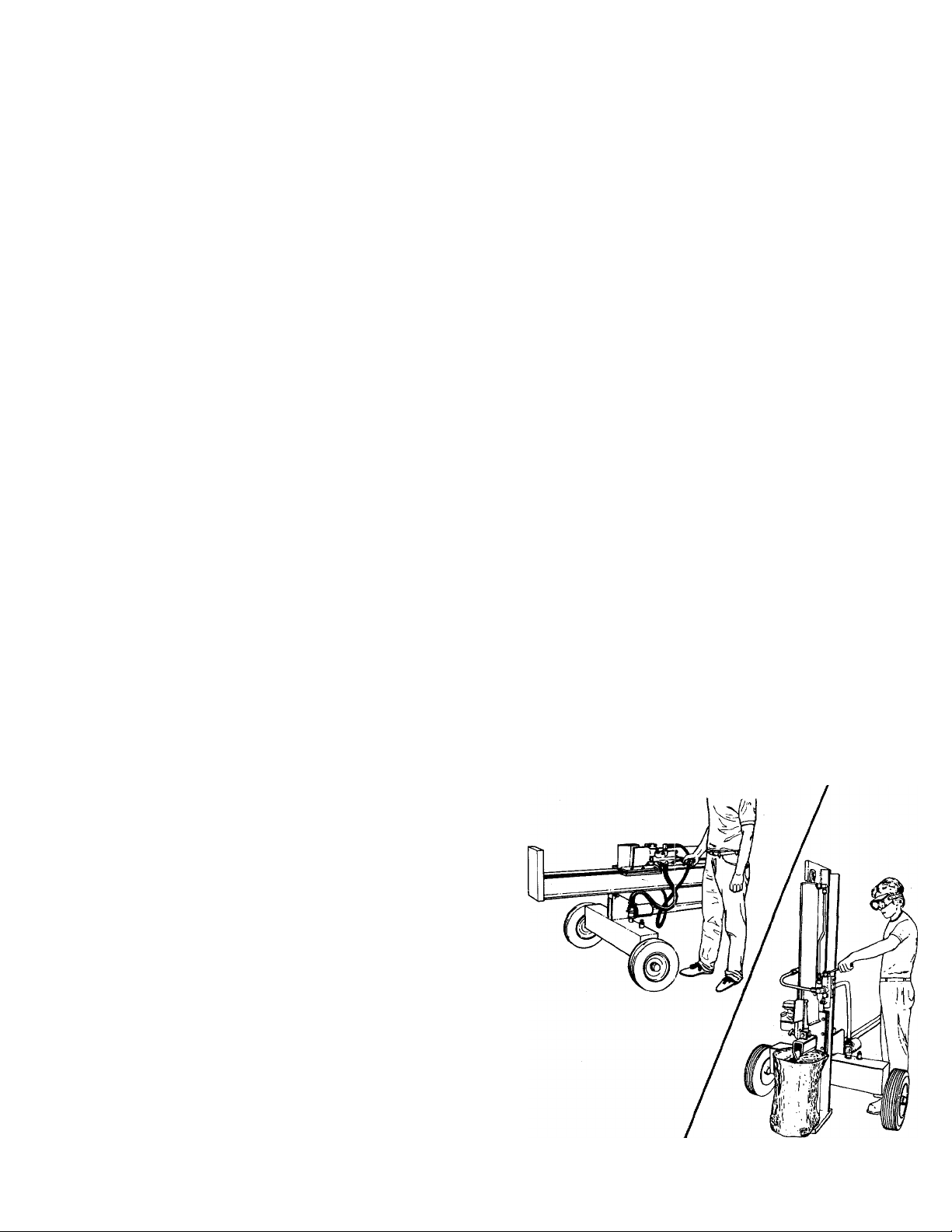
• Stand behind the reservoir tank when operating. See illustration.
PREPARATION
ik
Never wear loose clothing or jewelry that can be caught by moving
parts of your log splitter and pull you into it. Keep clothing away
from all moving parts of your log splitter.
Wear proper head gear to keep hair away from moving parts. Always
wear protective hearing devices as needed.
Always wear safety shoes. A dropped log can seriously injure your
foot.
Always wear safety glasses or goggles while operating your split
ter. A piece of splitting log could fly off and hit your eyes.
If you wear gloves, be sure they are tight fitting without loose cuffs
or draw strings.
Use your log splitter in daylight, or under good artificial light.
Never operate your splitter on slippery, wet, muddy or icy surfaces.
Safe footing is essential in preventing accidents. Never operate your
splitter while attached to a towing vehicle.
Page 4

• Know how to stop the unit and disengage the controls.
• Never place hands or feet between log and splitting wedge or be
tween log and end plate during forward or reverse stroke. To do
so may result in crushed or amputated fingers or toes, or worse,
you may lose an arm or foot.
• Do not straddle the splitter when using it. A slip in any position could
result in a serious injury.
• Do not step over your log splitter when the engine is running. You
may trip or accidentally activate the splitting wedge if you step over.
If you need to get to the other side, walk around.
• Never try to split two logs on top of each other. One may fly out
and injure you.
• When loading the log splitter, place your hands on the side of the
log, not at the ends. Never attempt to load your splitter while the
splitting wedge is in motion. You may get caught by the wedge and
injured.
• Only use your hand to operate the splitting wedge or control lever.
Never use your foot or a rope or any other extension device. This
could result in your ability to stop your splitter quickly enough and
cause injury.
• Always keep fingers away from any cracks that open in the log dur
ing splitting operation. They can quickly close and pinch or amputate
your fingers.
• Never attempt to split woods across the grain. Some types of wood
may burst or fly out of your splitter and result in injury to you or
a bystander.
• For logs that are not cut square, the longest portion of the log should
be rotated down and the most square end placed against the split
ting wedge.
• Keep your work area clean. Immediately remove split wood around
your splitter so that you do not stumble over it. Clean chips and
dirt off end plate (wood platform) after each log is split, or whenever
necessary to maintain flat contact between wood and end plate
(platform).
• Never move the log splitter while the engine is running.
• Never leave your log splitter unattended with the engine running.
Shut off the engine if you are leaving your splitter, even for a short
period of time. Someone could accidentally activate the splitting
wedge and be injured.
• Do not run engine in an enclosed area. Exhaust gases contain car
bon monoxide. This odorless gas can be deadly when inhaled.
• Be careful not to touch the muffler after the engine has been run
ning as it is HOT.
• If the equipment should start to vibrate abnormally, stop the engine
and check immediately for the cause. Vibration is generally a warn
ing of trouble.
• When cleaning, repairing or inspecting, make certain all moving parts
have stopped. Disconnect the spark plug wire and keep the wire
away from the plug to prevent accidental starting.
A
MAINTENANCE
Do not operate your splitter in poor mechanical condition or when
in need of repair.
Periodically check that all nuts, bolts, screws, hose clamps and
hydraulic fittings are tight to be sure equipment is in safe working
condition. Where appropriate, check all safety guards and shields
to be sure they are in the proper position. Never operate your split
ter with safety guards, shields or other protective features removed.
These safety devices are for your protection.
• Replace all damaged or worn parts such as hydraulic hoses and fit
tings immediately with manufacturer approved replacement parts.
• Do not change the engine governor settings or overspeed the engine.
This increases the hazard of personal injury. The maximum engine
speed is preset by the manufacturer and is within safety limits.
• Do not alter your splitter in any manner such as attaching a rope
or extension to the control lever or adding to the width or height
of the wedge. Such alterations may cause your splitter to be unsafe.
• Perform all recommended maintenance procedures before you use
your splitter.
• Do not service or repair your log splitter without disconnecting the
spark plug wire.
• Never store the equipment with gasoline in the tank inside of a
building where ignition sources are present, such as hot water and
space heaters, clothes dryers and the like. Allow the engine to cool
before storing in any enclosure.
• Always store gasoline in an approved, tightly sealed container. Store
the container in a cool, dry place. Do not store in a building where
ignition sources are present.
• To reduce fire hazard, keep engine free of grass, leaves, wood chips,
and excessive grease and oil.
• The hydraulic system of your log splitter requires careful inspec
tion, along with the mechanical parts. Be sure to replace frayed,
kinked, or otherwise damaged hydraulic components.
• Fluid escaping from a very small hole can be almost invisible. Do
not check for leaks with your hand. Escaping fluid under pressure
can have sufficient force to penetrate skin, causing serious personal
injury. Leaks can be located by passing a piece of cardboard or wood
over the suspected leak and looking for discoloration.
• Should it become necessary to loosen or remove any hydraulic fit
ting or line, be sure to relieve all pressure by shutting off the engine
and moving the control handle back and forth several times.
• Do not remove the cap from the hydraulic tank or reservoir while
your log splitter is running. Hot oil under pressure could cause injury.
• The pressure relief valve on your splitter is preset at the factory.
Do not adjust the valve. Only a qualified service technician should
perform this adjustment.
• Completely drain fuel tank prior to storage. This guards against ac
cumulation of fuel fumes which could result in a fire hazard.
• Never store log splitter outside without a waterproof cover. Rain
will cause rust on the inside of the cylinder.
A
TOWING
• This unit should not be towed on any street, highway or public road
without checking the existing federal, local or state vehicle re
quirements. Any licensing or modifications such as taillights, etc.,
needed to comply with the existing federal, local or state vehicle
requirements is the sole responsibility of the purchaser.
• Before towing, be certain the log splitter is correctly and securely
attached to the towing vehicle, and the safety chains are in place.
Leave slack in chains for turning allowance.
• Do not allow anyone to sit or ride on your splitter. They can easily
fall off and be seriously injured.
NOTE: This unit is equipped with an internal combustion engine and should not be used on or near any unimproved forest-covered, brush-covered
or grass-covered land unless the engine’s exhaust system is equipped with a spark arrester meeting applicable local or state laws (if any). If
a spark arrester is used, it should be maintained in effective working order by the operator.
In the State of California the above is required by law (Section 4442 of the California Public Resources Code). Other states may have similar
laws. Federal laws apply on federal lands. A spark arrester for the muffler is available at your Sears Authorized Service Center.
Page 5
ASSEMBLY
IMPORTANT: This unit has been shipped without
gasoline or oil in the engine. After assembly, refer to
operation section of this manual for proper fuel and
engine oil information.
UNPACKING
Remove the log splitter parts from the carton by cut
ting the corners of the carton. Make certain all parts
and literature have been removed from the carton
before the carton is discarded.
All hardware for assentbly of the log splitter has been
placed in position on the various parts.
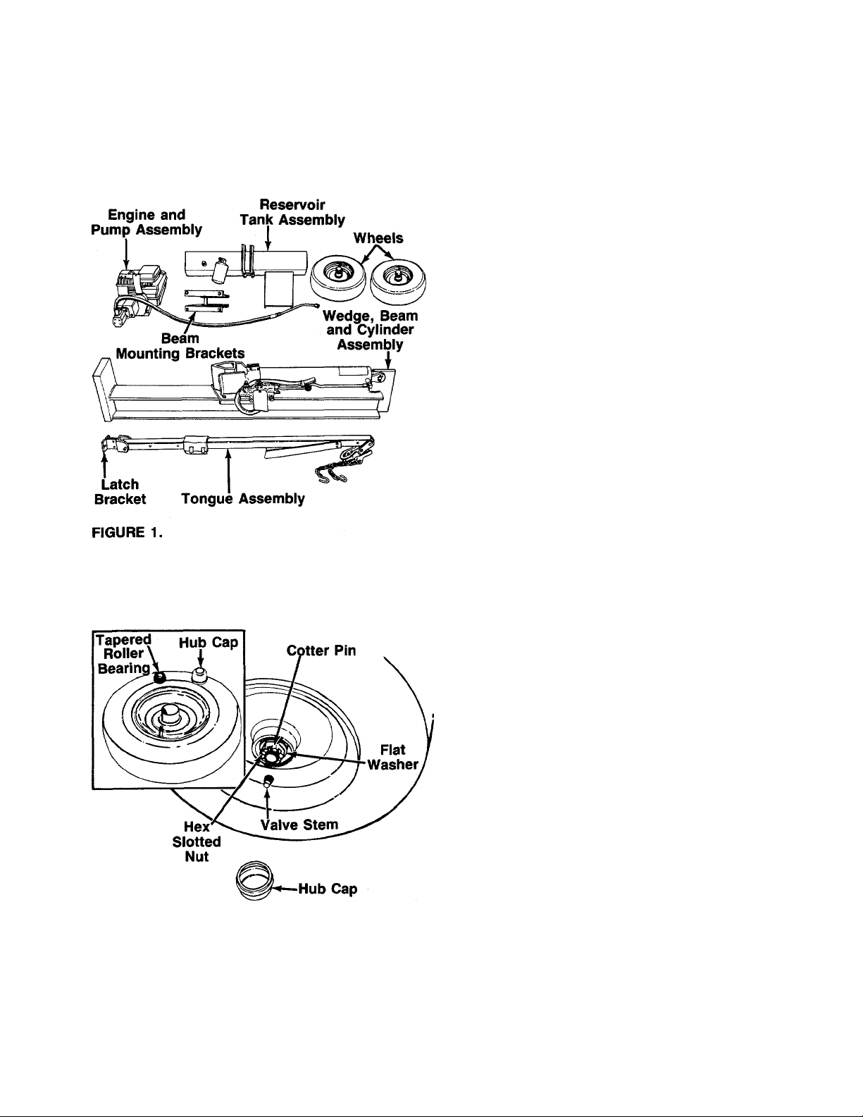
-PARTS IN CARTON (See figure 1)
Reservoir Tank Assembly
Engine and Pump Assembiy (Boited to bottom of
carton)
Tongue Assembiy
Wedge, Beam and Cylinder Assembly
TOOLS REQUIRED FOR ASSEMBLY
(2) 9/16" Wrenches*
(1) 5/8" Wrench*
(1) 11/16" Wrench*
(2) 1/2" Wrenches*
(1) Adjustable Wrench
(1) Knife (to remove cable tie)
(1) Screwdriver
‘Adjustable Wrenches may be used.
OTHER MATERIALS REQUIRED FOR ASSEMBLY:
Engine Oil
Unleaded Gasoline (regular grade gasoline is an
acceptable substitute)
Approximately 7.6 Gallons of Dexron II Automatic
Transmission Fluid
FIGURE 2.
INSTALLATION 01= WHEELS
Attach the wheels to the reservoir tank as follows. See
-figure 2.
• Pry off the hub caps which are attached to the
wheels. Remove one tapered roller bearing from in
side each wheel. See inset.
• Remove the cotter pin, hex slotted nut and flat
washer from each axle.
• Place one wheel on each axle, with the valve stem
facing outward.
• Pack the tapered roller bearings with wheel bearing
grease, and place one on each axle.
• Replace one flat washer on each axle. Secure with
hex slotted nut. Tighten slotted nut until snug, then
back off approximately 1/3 turn or until one of the
slots on the slotted nut lines up with the hole in the
axle.
• Check the assembly of the wheels. There should be
no side to side play, and the wheel should spin freely.
• Place hub caps in position on wheels and tap on with
a rubber maliet or plastic hammer.
Page 6
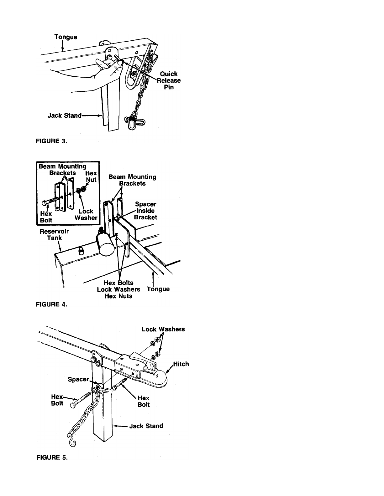
ATTACHING TONGUE TO RESERVOIR TANK
• The tongue is shipped with the jack stand aiready
attached to the tongue. The jack stand is in the
transport position. Remove the quick release pin.
Pivot the jack stand to the operating position (90°),
—and secure with the quick release pin. See figure 3.
NOTE: If necessary, loosen the bolt which holds the
hitch to the tongue, and pivot hitch out of the way.
• Remove the latch bracket which has been assem
bled to the other end of the tongue for shipping pur
poses only by removing another quick release pin.
Refer to figure 1. This bracket will be reassembled
to the beam on page 7. Replace the quick release
pin in the latch bracket.
• Remove the two hex bolts, lock washers and hex
nuts on the front of the reservoir tank. Two 9/16"
wrenches are required. Place the tongue In position,
and secure with hardware just removed. See figure
4.
ATTACHING THE BEAM MOUNTING BRACKETS
• Using two 3/4" or adjustable wrenches, remove the
hex nut, lock washer and hex bolt from the bracket
on the reservoir tank. Make certain the spacer re
mains inside the bracket on the reservoir tank. See
—figure 4.
• Place one beam mounting bracket against each side
of the bracket on the reservoir tank as shown in
figure 4. Secure with hardware just removed.
Hex Nuts
INSTALLING THE HITCH
• Using two 9/16" wrenches, remove the two long hex
bolts, lock washers and hex nuts which are assem
bled through the sides of the hitch and the tongue.
Do not remove the chain and spacer from the one
hex bolt.
• Place the hitch in position on the end of the tongue.
—Secure with hardware just removed. See figure 5.
Page 7
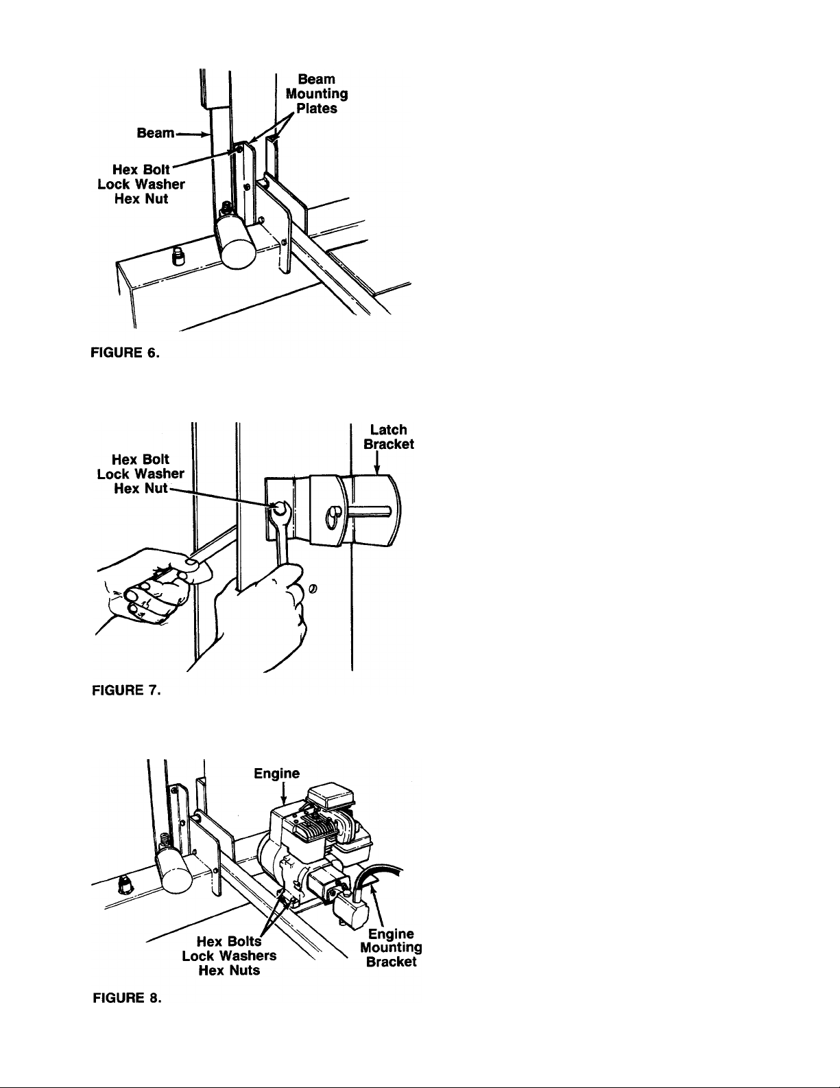
ATTACHING THE WEDGE, BEAM AND
CYLINDER ASSEMBLY
• Stand the wedge, beam and cylinder assembly
upright.
• Remove the four hex bolts, lock washers and hex
nuts from the beam mounting plates. A 5/8" and an
—11/16" wrench are required. See figure 6.
• Roll the reservoir tank assembly in position against
the beam. Secure the beam mounting plates to the
beam with hardware just removed. Tighten securely.
ATTACHING THE LATCH BRACKET
• Remove the two he>x bolts, lock washers and hex
nuts from the beam, using two 1/2" wrenches.
• With the beam still in the upright position, place the
—pivot latch on the beam as shown in figure 7. Secure
with hex bolts, lock washers and hex nuts just re
moved. Tighten securely.
ATTACHING THE ENGINE AND PUMP ASSEMBLY
• Using two 1/2" wrenches, remove the four hex bolts,
lock washers and hex nuts which secure the base
of the engine to the bottom of the shipping carton.
• Place the engine and pump assembly in position on
the engine mounting bracket as shown in figure 8.
—Secure with hardware just removed. Tighten
securely.
Page 8
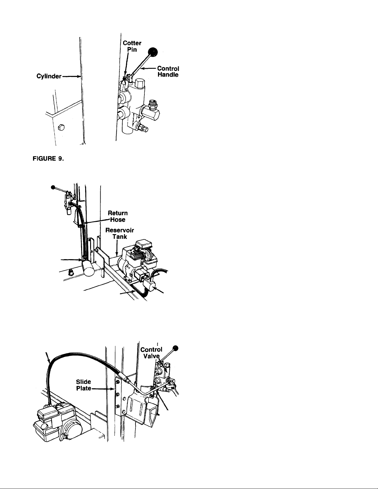
ATTACHING THE CONTROL HANDLE
• The control handle and the return hose are attached
to the metal pressure tube with a cable tie for ship
ping purposes only. Cut and remove the cable tie.
• The bottom of the control handle is already attached
to the valve with a cotter pin and clevis pin. Remove
the second cotter pin and clevis pin which is attach
ed to the valve only. Place the handle in position,
and secure using the second cotter pin and clevis
—pin. See figure 9.
Control
Valve
Filter
Head
FIGURE 10.
Pressure
Hose
Suction-
Hose
Pump
ATTACHING THE HOSES
SUCTION HOSE
• The suction hose is attached to the reservoir tank,
beneath the engine mounting plate. Loosen the hose
clamp on the free end of the hose using a
screwdriver.
• Attach the end of the hose to the fitting on the bot-
—tom of the pump. See figure 10. Place the hose
clamp at the base of the fitting, and tighten securely.
RETURN HOSE
• The return hose is attached to the bottom of the
valve. Loosen the hose clamp on the free end of the
hose using a screwdriver.
• Attach the end of the hose to the fitting on top of the
filter head. See figure 10. Place the hose clamp at
the base of the fitting, and tighten securely.
PRESSURE HOSE
The pressure hose is attached to the top of the pump.
-Route the hose as shown in figure 11. Place the metal
pressure tube in position on the fitting on top of con
trol valve. Secure with the compression nut on the
pressure tube, using an adjustable wrench. Make cer
tain the metal pressure tube is positioned so that the
pressure hose is above the slide plate as shown.
FIGURE 11.
Metal
Pressure
Tube
FINAL ASSEMBLY
• Make certain all nuts, bolts and hose clamps are
tightened securely.
• Before operating the log splitter, make certain to
follow the “Initial Preparation” instructions in the
Operation Section, page 9.
Page 9
OPERATION
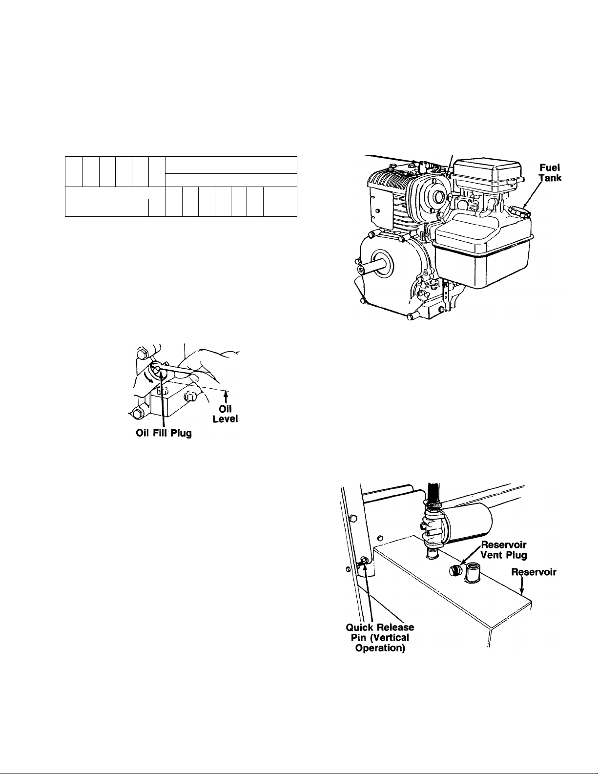
GAS AND OIL FILL-UP
NOTE: Engine is shipped without oil. Fill crankcase with
oil before starting. Be very careful not to allow dirt to
enter the engine when checking or adding oil or fuel.
Recommended SAE Viscosity Grades
nr
30Wor10W30 >
C 5W30
'rnrn
0
-20° 0° 32°
60°
80
Temperature range expected before next oil
change. All oils must be A.P.I. service classification
SD, SE or SF.
• Fill engine with oil by removing oil fill plug. See figure
12. With engine level, fill engine with oil to point of
overflowing. Capacity is 1 Va pints. Replace oil fill
plug.
00°
carburetor are empty. Use fresh fuel next season. See
storage section of this manual for additional infor
mation.
Never use engine or carburetor cleaner products in the
fuel tank or permanent damage may occur.
Spark
____
Muffler
Plug,
Wire
and
Cover
FIGURE 13.
NOTE: Use clean oil and fuel. Store in approved, clean,
covered containers. Use clean fill funnels.
FIGURE 12.
• Fill fuel tank. See figure 13. Use fresh, clean, un
leaded automotive gasoline. Capacity is 3 quarts.
WARNING: FILL TO WITHIN Va INCH OF
TOP OF FUEL TANK TO PREVENT
A
SPILLS AND TO ALLOW FOR FUEL EX
PANSION. IF GASOLINE IS ACCIDENTLY
SPILLED, MOVE LOG SPLITTER AWAY
FROM AREA OF SPILL. AVOID
CREATING ANY SOURCE OF IGNITION
UNTIL GASOLINE VAPORS HAVE DIS
APPEARED.
Caution: Experience indicates that alcohol blended
fuels (called gasohol or using ethanol or methanol) can
attract moisture which leads to separation and forma
tion of acids during storage. Acidic gas can damage
the fuel system of an engine while in storage. To avoid
engine problems, the fuel system should be emptied
before storage for 30 days or longer. Drain the gas tank,
start the engine and let it run until the fuel lines and
INITIAL PREPARATION
• Place log splitter on a firm, level surface. For ver
tical operation, remove the quick release pin from
the latch bracket. Place the beam in the vertical posi
tion. Place the quick release pin through the holes
in the beam mounting plates and the brackets on the
reservoir tank. See figure 14.
FIGURE 14.
• Lubricate the beam area where beam will slide with
engine oil (DO NOT USE GREASE). Make certain
to oil both front and back of the beam face.
Page 10

• Fill the reservoir tank as follows.
a. Remove reservoir vent plug. See figure 14. Using
Dexron II automatic transmission fluid, fill reser
voir to the top. Replace vent plug securely.
b. Disconnect the spark plug wire. Prime the pump
by pulling the recoil starter, to turn the engine
over, approximately 10 times. Reconnect the
spark plug wire.
c. Start engine. Use the control handle to extend the
wedge to the far extended position. Leave the
wedge in this position (do not retract).
d. Refill tank to within 1 ¥2" to 2" from the top of the
tank. Total capacity of system is approximately
7.6 gallons.
e. Now retract the wedge. Extend and retract the
wedge fully 10 to 12 complete cycles to remove
trapped air in the system (system is “self
bleeding”).
f. Refill the reservoir to within 1V
top of the tank. Much of the original fluid has been
drawn into the cylinder and hoses. Make certain
to refill the reservoir, to prevent extreme damage
to the hydraulic pump. Failure to refill the tank will
2
" to 2" from the
void your warranty.
NOTE: Some fluid may overflow from the vent plug as
the system builds heat and the fluid expands and seeks
its own level.
TO START ENGINE
• Place throttle control lever on the engine in FAST
position. See figure 15.
• Place choke lever in CHOKE position.
NOTE: A warm engine may not require choking.
• Grasp starter handle and pull rope out slowly until
engine reaches start of compression cycle (rope will
pull slightly harder at this point). Let the rope rewind
slowly.
• Pull rope with a rapid, continuous, full arm stroke.
Keep a firm grip on the starter handle. Let the rope
rewind slowly. Do not let starter handle snap back
against starter.
• Repeat preceding instructions 3 and 4 until engine
fires. When engine starts, move choke lever halfway
between CHOKE and RUN.
• Move throttle control lever to IDLE position for a few
minutes warm-up. Gradually move choke lever to
RUN position as engine warms up.
NOTE: In order to idle smoothly, a new engine may re
quire 3 to 5 minutes running above slow idle speed.
Idle speed has been adjusted to be correct after this
break-in period.
• If weather is cold, run wedge up and down beam 6
to 8 times to circulate the hydraulic fluid, which will
warm and thin the fluid.
WARNING: DO NOT OPERATE THE LOG
SPLITTER WITHOUT THE PROPER
A
AMOUNT OF TRANSMISSION FLUID IN
THE RESERVOIR TANK.
BEFORE STARTING
Before each use, check the following:
• Place log splitter on a firm, level surface. For ver
tical operation, remove the quick release pin from
the latch bracket. Place the beam in the vertical posi
tion. Place the quick release pin through the holes
in the beam mounting piates and the brackets on the
reservoir tank. See figure 14.
• Remove the vent piug and check the fluid level. Fluid
level should be IVa" to 2" from the top of the tank.
IMPORTANT: Reservoir tank must be full as instructed.
Low fluid level will damage the pump and void your
warranty.
• Lubricate the beam area where beam will slide with
engine oil (DO NOT USE GREASE). Make certain
to oil both front and back of the beam face.
• Fill gasoline tank as instructed on page 9.
• Attach spark plug wire and cover to spark plug. See
figure 13.
•
TO STOP ENGINE
• Move throttle control lever to OFF position.
• Disconnect spark plug wire from spark plug to pre
vent accidental starting while equipment is unat
tended.
USING THE LOG SPLITTER
Use the log splitter only on a level, hard surface.
Never stand next to the splitting wedge when
operating the log splitter. Always stand behind the
reservoir tank. See figures 16 and 17. Never attempt
to cut a log in half sideways. Always split the log
lengthwise. Maximum length of log to be split is 24".
10
Page 11

WARNING: ALWAYS USE THE LOG
SPLITTER IN THE VERTICAL POSITION
A
The control handle has three positions:
FORWARD—Push the control handle down for vertical
operation, push it forward for horizontal operationsplitting wedge moves toward the end plate. Con
trol handle will return to neutral position as soon as
handle is released.
NEUTRAL (Middle position)—Splitting wedge stops
in place.
REVERSE—Push the control handle upward for ver
tical operation, push it toward the rear for horizontal
operation—Splitting wedge returns. The control han
dle will lock in the reverse position, and will return
to neutral automatically when the reverse stroke is
complete.
ONLY WHEN SPLITTING HEAVY LOGS.
• Move the control handle to reverse position to return
the splitting wedge.
WARNING: IIF THE FLUID BECOMES EX
CESSIVELY HOT AT ANY TIME DURING
A
OPERATION, STOP THE UNIT AND
ALLOW THE FLUID TO COOL DOWN.
MAXIMUM PERFORMANCE WILL NOT BE
OBTAINED FROM OUR LOG SPLITTER IF
THE FLUID IS TOO HOT. USE EXTREME
CAUTION AS CONTACTING HOT FLUID
COULD RESULT IN SERIOUS PERSONAL
INJURY.
TO OPERATE LOG SPLITTER:
• Set throttle at maximum speed (3450-3600 RPM).
• Place the log upright, on top of end plate for vertical
operation, and on top of beam for horizontal
operation.
• Push the control handle to forward position until the
splitting wedge just contacts the log. Release the
control handle.
• Step behind the reservoir tank (see figures 16 or
17) and push the control handle in forward position
until the log is split.
TO TRANSPORT LOG SPLIHER
• Lower the beam to its horizontal position. Make cer
tain the latch bracket is latched securely around the
tongue and secured with the quick release pin.
• Remove the quick release pin which secures the jack
stand. Pivot it up against the tongue, and secure with
the quick release pin.
• Attach the hitch to a towing vehicle, making certain
to latch securely. Attach the safety chains to the tow
ing vehicle.
ADJUSTMENT
SPLITTING WEDGE
As normal wear occurs, periodically adjust the bolts on
the slide plate (beneath the splitting wedge) as follows
to eliminate the excess; space between the wedge plate
and the beam. See figure 18.
11
Page 12

Hex Bolts
Bolts
FIGURE 18.
• Loosen the three hex bolts on top of the slide plate
(beneath the splitting wedge).
• Back the two adjustment bolts on the side of the slide
plate out slowly until the wedge assembly will slide
on the beam. Tighten the lock nuts securely against
the base of the slide plate to hold the bolts in this
position.
• Retighten the three hex bolts on top of the slide plate.
Start engine and allow to warm for five minutes.
With throttle in FAST position, close needle valve
clockwise (). until engine Starts to lose speed
(lean mixture). Then slowly open needle valve
counterclockwise () until engine JUST BEGINS
to run unevenly. This mixture should be rich enough
for best performance under load.
Place throttle control in IDLE position:
a.
If engine idles, no further adjustment is
necessary.
b.
If engine idles too fast, turn idle speed adjusting
screw counterclockwise ( ) until slower speed
is obtained.
c. If engine dies, turn idle speed adjusting screw 'A
turn clockwise (/^ ). Place throttle control in
FAST position and restart engine.
d. Move throttle control to IDLE position. If engine
does not idle, repeat step c.
• Test the engine by splitting. If engine tends to stall
or die out, it usually indicates that the mixture is
slightly lean and it may be necessary to open ( f~\ )
the needle valve slightly to provide a richer mixture.
This richer mixture may cause a slight unevenness
in idling.
CARBURETOR ADJUSTMENT
WARNING: IF ANY ADJUSTMENTS ARE
MADE TO THE ENGINE WHILE THE
A
Minor carburetor adjustment may be required to com
pensate for differences in fuel, temperature, altitude or
load.
NOTE: A DIRTY AIR CLEANER WILL CAUSE ENGINE
TO RUN ROUGH. BE CERTAIN AIR CLEANER IS
CLEAN AND ATTACHED TO THE CARBURETOR
BEFORE ADJUSTING CARBURETOR. DO NOT
MAKE UNNECESSARY ADJUSTMENTS. FACTORY
SETTINGS ARE SATISFACTORY FOR MOST AP
PLICATIONS AND CONDITIONS.
Never attempt to change maximum engine speed. It
is pre-set at the factory and shouid be changed only
by a qualified service technician who has the necessary
equipment.
The Carburetor may need re-adjusting if engine lacks
power or does not idle properly. If adjustments are
needed, proceed as follows.
• Close needle valve (see figure 19) clockwise
() finger tight only. Forcing may cause damage.
Then open 1V2 turns counterclockwise ( ).
ENGINE IS RUNNING (e.g. CAR
BURETOR), KEEP CLEAR OF ALL MOV
ING PARTS. BE CAREFUL OF HEATED
SURFACES AND MUFFLER.
MAINTENANCE
WARNING: ALWAYS STOP THE ENGINE
AND DISCONNECT THE SPARK PLUG
A
RESERVOIR FLUID
Check the hydraulic fluid level in the log splitter reser
voir tank before each use. Fluid level should be 1-1/2"
to 2” from the top of the tank.
Change the hydraulic fluid in the reservoir every 100
hours of operation. Disconnect the suction hose from
the bottom of the reservoir tank, and drain the fluid in-
WIRE BEFORE PERFORMING ANY
MAINTENANCE OR ADJUSTMENTS.
12
Page 13

to a suitable container. Refill using only Dexron II
automatic transmission fluid, as instructed in the “In
itial Preparation” section of this manual, page 9. Also,
make certain to change the hydraulic filter.
Capacity is VA pints. Refer to “Gas and Oil Fill-Up”
on page 9.
• Replace oil fill plug.
NOTE: Drain the fluid and flush the reservoir tank and
hoses with kerosene whenever any repair work is per
formed on the tank, hydraulic pump or valve. Con
taminants in the fluid will damage the hydraulic
components. (Should be performed by your SEARS
Service Center.
WARNING: USE EXTREME CAUTION
WHEN WORKING WITH KEROSENE, AS
A
IT IS AN EXTREMELY FLAMMABLE
FLUID.
HYDRAULIC FILTER
Change the hydraulic filter every 50 hours of operation.
Use only a 10 micron hydraulic filter. Order part number
723-0405.
BEAM AND SPLiniNG WEDGE
Lubricate both sides of the beam where it contacts the
splitting wedge with engine oil before each use to ob
tain years of service. However, normal wear will occur.
The wedge plate on the log splitter is designed so the
gibs on the side of the wedge plate can be easily re
moved and rotated and/or turned over for even wear.
Make certain to readjust the adjustment bolts so wedge
moves freely, but no excess space exists between the
wedge plate and beam.
HOSE CLAMPS
Check the hose clamps on the suction hose (attached
to bottom of the pump) for proper tightness before each
use. Check the hose clamps on the return hose at least
once a season.
AIR CLEANER
The air cleaner prevents damaging dirt, dust, etc., from
entering the carburetor and being forced into the engine
and is important to engine life and performance.
Never run your engine without air cleaner complete
ly assembled.
TO SERVICE AIR CLEANER:
Clean cartridge at three month intervals or every 25
hours, whichever occurs first. See figure 20. Service
more often under dusty conditions.
• Loosen screws and tilt cover as illustrated.
• Carfeully remove pre-cleaner and cartridge.
• Clean cartridge by tapping gently on a flat surface.
If very dirty, replace cartridge and pre-cleaner or
clean as follows;
a. Wash in a low or non-sudsing detergent and
warm water solution. CAUTION: Do not use
petroleum solvents such as kerosene to clean
cartridge.
b. Rinse thoroughly with flowing water from inside
out until water is clear.
c. Allow cartridge to stand and air dry thoroughly
before using. DO NOT OIL CARTRIDGE OR
PRE-CLEANER. DO NOT USE PRESSURIZED
AIR TO CLEAN OR DRY CARTRIDGE.
• Install cartridge and pre-cleaner. Then close cover
and fasten screws securely.
Screw
Spacer
ENGINE LUBRICATION
Your four-cycle engine will normally consume some oil;
therefore, check engine oil level regularly—approxi
mately every five hours of operation and before each
usage. Stop engine and wait several minutes before
checking oil level. With engine level, the oil must be
even with the oil fill (refer to figure 12). Change engine
oil after the first five hours of operation, and every
twenty-five hours thereafter.
• Drain oil while engine is warm.
a. Remove oil drain plug. Refer to figure 12. Catch
oil in a suitable container.
b. When engine is drained of all oil, replace drain
plug securely.
• Refill with fresh oil. Above 32°, use oil labeled SAE
30W or 10W30. Below 32°, use oil labeled 5W20.
Pre-Cleaner
Cartridge
Base
FIGURE 20.
CLEAN ENGINE
Clean engine periodically. Remove dirt and debris with
a cloth or brush. Cleaning with a forceful spray of water
is not recommended as water could contaminate the
fuel system.
13
Page 14

Yearly or every 25 hours, whichever occurs first,
remove the blower housing and clean the areas shown
in figure 21 to avoid overspeeding, overheating and
engine damage. Clean more often if necessary.
A
WARNING: NEVER HIT THE PUMP
SHAFT IN ANY MANNER, AS ANY BLOW
WILL CAUSE PERMANENT DAMAGE TO
THE PUMP.
WARNING: PERIODICALLY CLEAN MUF
FLER AREA TO REMOVE ALL GRASS,
A
DIRT AND COMBUSTIBLE DEBRIS.
Clean Out
> Chaff and Dirt
FIGURE 21.
SPARK PLUG
The spark plug should be cleaned and the gap reset
to .030" at least once a season or every 50 hours of
operation. See figure 22. Spark plug replacement is
recommended at the start of each season. Refer to
engine parts list for correct spark plug type.
NOTE: Do not blast clean spark plug. Spark plug
should be cleaned by scraping or wire brushing and
washing with a commercial solvent.
When replacing the flexible pump coupling, proceed
as follows.
• Place the coupling half onto the engine shaft. Make
certain there is clearance between the coupling half
and the engine. Tighten the set screw.
• Mount the pump onto the coupling support bracket.
Tighten securely.
• Carefully slide coupling half onto pump shaft (make
certain set screw is loose). Slide the key into place
on the shaft.
• Install the nylon “spider” insert into coupling half on
the engine shaft.
• Place the coupling shield in position on the hex bolts.
Rotate the keyway on the pump shaft so it is toward
the bottom.
• Attach the coupling support bracket to the hex bolts,
carefully sliding the coupling half over the “spider”
insert. Secure coupling shield and coupling support
bracket with lock washers and hex nuts. Tighten
securely.
• Adjust the two coupling halves (steel) so there is be
tween .010" and .060" clearance between the two
halves (at least the thickness of a matchbook cover,
up to 1/16" maximum). See figure 23. Tighten the
set screw in the coupling half on the pump shaft.
MUFFLER
Do not operate the log splitter without a muffler or
tamper with the exhaust system. Damaged mufflers or
spark arresters could create a fire hazard. Inspect
periodically, and replace if necessary. If your engine
is equipped with a spark arrester screen assembly,
remove every 50 hours for cleaning and inspection.
Replace if damaged.
FLEXIBLE PUMP COUPLER
The flexible pump coupler is a nylon “spider” insert,
located between the pump and engine shaft. The align
ment is very critical. Over a period of time, the coupler
will harden and deteriorate. For a replacement flexible
pump coupler, order part number 717-0891.
NOTE: Make certain proper clearance is obtained
before tightening set screw.
PUMP
TIRE PRESSURE
Check sidewall of tire for manufacturer’s recommended
maximum tire pressure. If this information does not ap
pear on your tire, maximum tire pressure under any cir
cumstances is 30 p.s.i. Equal pressure should be
maintained on both tires.
14
Page 15

INSTALLATION OF TIRE TO RIM
WARNING: THE FOLLOWING PRO
CEDURE MUST BE FOLLOWED WHEN
A
Be certain rim is clean and free of rust.
Lubricate both the tire and rim generously.
Never inflate to over 30 p.s.i. to seat beads. Ex
cessive pressure when seating beads may cause
tire/rim assembly to burst with force sufficient to
cause serious injury.
It is important to prevent gum deposits from forming
in essential fuel system parts such as the carburetor,
fuel hose or fuel tank during storage. Also, experience
indicates that alcohol blended fuels (called gasohol or
using ethanol or methanol) can attract moisture which
leads to separation and formation of acids during
storage. Acidic gas can damage the fuel system of an
engine while in storage.
To avoid engine problems, the fuel system should be
emptied before storage of 30 days or longer. Follow
these instructions.
• Drain the fuel tank. Start the engine, and let it run
until the fuel lines and carburetor are empty.
REMOVING OR INSTALLING A TIRE TO
THE RIM.
OFF-SEASON STORAGE
* •
Remove spark plug, pour approximately ¥2 ounce
(approximately one tablespoon) of engine oil into
cylinder and crank slowly to distribute oii. Replace
spark plug.
• Clean the engine and the entire log splitter
thoroughiy.
• Wipe unit with an oiled rag to prevent rust, especial
ly wedge and beam.
NOTE: When storing any type of power equipment in
an unventilated or metal storage shed, care should be
taken to rustproof the equipment by coating with a light
oil or silicone.
• The tongue can be removed and reattached in an
upright position as shown in figure 24 to take less
space when storing.
• Store unit in a ciean, dry area.
WARNING: DO NOT DRAIN FUEL WHILE
A
Drain all the oil from the crankcase (this should be
done after the engine has been operated and is stiil
warm) and refill the crankcase with fresh oil.
Protect the inside of the engine for storage as
follows.
SMOKING, OR IF NEAR AN OPEN FIRE.
FIGURE 24.
15
Page 16

TROUBLE SHOOTING GUIDE
Trouble
Engine fails to start
Engine runs erratic
Possible Cause(s)
1. Fuel tank empty, or stale fuel.
2. Blocked fuel line.
3. Spark plug wire disconnected.
4. Faulty spark plug.
1. Unit running on CHOKE.
2. Spark plug wire loose.
3. Blocked fuel line or stale fuel.
4. Water or dirt in fuel system.
5. Dirty air cleaner.
6. Carburetor out of adjustment.
Engine overheats 1. Engine oil level low.
2. Air flow restricted.
3. Carburetor not adjusted properly.
Corrective Action
‘1. Fill tank with clean, fresh gasoline.
2. Clean fuel line.
3. Connect wire to spark plug.
4. Clean, adjust gap or replace.
1. Move choke lever to OFF position.
2. Connect and tighten spark plug
wire.
3. Clean fuel line; fill tank with clean
fresh gasoline.
4. Drain fuel tank. Refill with fresh
fuel.
5. Clean air cleaner as instructed in
Maintenance section.
6. Adjust carburetor (see Carburetor
Adjustment in Adjustment section
of this manual).
1. Fill crankcase with proper oil.
2. Remove blower housing and
clean as instructed in
Maintenance section.
3. Adjust carburetor (see Carburetor
Adjustment in Adjustment section
of this manual).
Will not split logs Reservoir fluid level low. Check and fill reservoir tank as
instructed in Operation section
of this manual.
Leaking cylinder 1. Broken seals.
2. Scored cylinder.
1. Replace seals.*
2. Replace cylinder.*
NOTE: For repairs beyond the minor adjustments iisted above, piease contact your nearest SEARS Service
Center.
*Shouid be performed by your SEARS Service Center only.
16
Page 17

IMPORTANT INFORMATION FOR LOG SPLITTER USERS
ALWAYS:
Use clean fluid and check fluid level regularly
Use Dexron II Automatic Transmission Fluid
Use a filter (clean or replace regularly)
Use a breather cap on fluid reservoir
Keep end of reservoir return tube below fluid level
Make certain pump is mounted and aligned properly
Use a flexible “spider” type coupling between engine
and pump driveshafts
Keep hoses clear and unblocked
Bleed air out of hoses before operating
Flush and clean hydraulic system before startup after
any malfunction or servicing
Use “pipe dope” on all hydraulic fittings
Allow time for warmup before splitting wood
Prime the pump before initial startup by turning over
the engine with spark plug disconnected
Split wood with the grain (lengthwise) only
NEVER:
Use fluid below 0° F., or above 150° F.
Use a solid engine/pump coupling
Force pump when mounting
Operate through relief valve for more than several
seconds
Attempt to adjust unloading or relief valve settings
without pressure gauges
Operate with air in hydraulic system
Use Teflon tape on hydraulic fittings
Warm up engine apart from pump in cold weather
Attempt to cut wood across the grain
CONDITIONS WHICH WILL VOID YOUR WARRANTY
1. Failure to maintain proper fluid level in reservoir will void your warranty, causing permanent damage to
pump by allowing air to be drawn into pump. Fluid will become foamy. Refer to “Initial Preparation” in the
Operation Section of this manual.
2. Changing the relief valve setting or pressure adjustment of control valve without proper knowledge and
instruction from the factory will void your warranty. A very minor adjustment could destroy the structural and
safety limits for which the unit was designed. The system will produce more power than the structure will
withstand. Higher pressure could cause the hoses to burst, cylinder to rupture and intense fluid releases,
which could result in serious personal injury.
3. Disassembling the pump will void your warranty. If replacment is necessary, merely disconnect and replace.
Do not attempt to adjust pump settings, as they are adjusted by the manufacturer at the factory.
4. Use of incorrect hydraulic fluid will void your warranty. Use only Dexron II automatic transmission fluid.
Any other type of fluid must be approved by a direct factory representative.
5. The flexible pump coupler must be inspected regularly. Allowing the coupler to deteriorate will void your
warranty. Deterioration of spider insert and prolonged use after deterioration will destroy pump bearings and
engine bearings, along with total destruction of coupler hubs.
6. Improper beam lubrication will cause premature wear and looseness. Lubricate the beam regularly. Lack
of lubrication will void your warranty.
7. Improper adjustment of splitting wedge will void your warranty. Become familiar with the proper tolerance
required for adjustment of the splitting wedge as instructed in the adjustment section of this manual.
a. If wedge is too loose, cylinder beam and wedge wear will result. Allowing the wedge to loosen and be
used under operating stress will cause damage which will not be covered under warranty.
b. If wedge is too tight, severe beam damage will result which will not be covered under warranty.
8. Do not overheat the hydraulic system. Excessive heat will destroy the hydraulic system with hardened 0-rings
and excessive friction.
9. Do not attempt to start in temperatures under 20° F. without pre-heating fluid in reservoir. Excessively
cold fluid cannot circulate and draw into pump. Warranty will be void.
10. Repair any leaks in hydaulic system immediately. Unattended leaks will cause air to enter system and/or
decrease fluid level in reservoir, causing damage to the hydraulic system which will not be covered by warranty.
17
Page 18

HOW YOUR LOG SPLITTER OPERATES
Cylinder Rod
r"
Reservoir
THE PUMP
A two-stage log splitter pump has one large and one
small gear section, using common inlet and outlet ports.
Below a preset pressure (called unloading pressure)
a check valve between the two gear sections allows
both flows to combine. Together, the two gear sections
create a large volume flow which produces rapid
cylinder movement under low load conditions.
Above unloading pressure, a pilot pressure line(which
simulates actual pressure at the cylinder) activates the
unloading valve, which causes the flow to bypass the
large gear section and return to the pump inlet area.
The small gear section is now operating alone, and will
generate the higher pressure necessary for the actual
log splitting operation.
The original factory setting for the unloading valve is
designed to provide maximum flow while remaining
below engine stalling load. Note: Splitting capability
is not affected by the setting of the unioading valve.
Do not attempt to adjust or reset it without a
pressure gauge (should be performed by an
authorized SEARS Serve Center only).
THE DIRECTIONAL VALVE AND CYLINDER
From the pump, oil flows to a four way, three position
directional valve. At the neutral position this valve
directs the flow back to the oil reservoir, bypassing the
cylinder. When the directional valve is directing the flow
to the back of the cylinder, the cylinder rod extends
quickly until it meets significant resistance. Upon
reaching unloading pressure, movement of the shaft
High Volume
Low Pressure
Gear Section
Cylinder
Piiot
Pressure
Line
Pump
Low Voiume
High Pressure
Gear Section
will slow but will continue forward. If the pressure
reaches a preset maximum (called relief valve pressure)
the relief valve, located within the directional valve, will
allow the flow to bypass the cylinder and return to the
reservoir. This can happen when the cylinder rod meets
excessive resistance, or when it reaches the end of its
stroke and can move no farther.
Note: Never operate at relief valve pressure for more
than a few seconds.
When the directional valve is directing the flow to the
front of the cylinder, the rod will retract quickly since
it is encountering no resistance. The relief valve will
momentarily bypass the flow at the end of the return
stroke but the directional valve should then automatical
ly return to the neutral position, directing the flow direct
ly into the reservoir. This serves to protect the pump
from possible damage due to prolonged operation at
relief valve pressure.
Because of the potential for system damage, the relief
valve is carefully and precisely preset by the
manufacturer.
Note: The user should not attempt to adjust or
change the setting of the relief valve.
OPERATIONAL PROBLEMS
If you have trouble with your log splitter, please refer
to the Hydraulic Trouble Shooting Guide on page 19.
Note: Readjustment of valves or disassembly of
pump should be performed by your SEARS Service
Center only.
18
Page 19

HYDRAULIC TROUBLE SHOOTING GUIDE
Problem Probable Cause(s)
Cylinder rod will not
move
Slow cylinder shaft
speed while
extending and
retracting
Engine runs but
wood will not split,
or wood splits too
slowly
A Broken driveshaft
B Loose shaft coupling
C Gear sections damaged
D Damaged relief valve
E Hydraulic lines blocked
F Too little oil to pump
G Damaged directional valve
H Blocked directional valve
A Gear sections damaged
B Excessive pump inlet vacuum
C Slow engine speed
D Damaged relief valve
E Too little oil to pump
F Air in oil
G Directional valve leaking internally
H Internally damaged cylinder
A Small gear section damaged
B Pump check valve leaking
C Excessive pump inlet vacuum
D Low relief valve setting
E Too little oil to pump
F Air in oil
G Directional valve leaking internally
H Overloaded cylinder
1 Internally damaged cylinder
Corrective Action
A Return unit for authorized repair
B Correct engine/tpump alignment as necessary
C Return unit for authorized repair
D Return directional valve for authorized repair
E Flush and clean hydraulic system
F Add oil to reservoir
G Return unit for authorized repair
H Flush and clean hydraulic system; return
unit for authorized repair
A Return unit for authorized repair
B Make certain pump inlet hoses are clear
and unblocked—use short, large
diameter inlet hoses
C Return unit for authorized repair
D Return unit for authorized repair
E Add oil to reservoir
F Add oil, clean reservoir, make certain oil
return tube is below oil level
G Return unit for authorized repair
H Return unit for authorized repair
A Return unit for authorized repair
B Return unit for authorized repair
C Make certain pump inlet hoses are
clear and unblocked; use short, large
diameter inlet hoses
D Adjust valve while using pressure gauge*
E Add oil to reser/oir
F Add oil, clean reservoir, make certain oil
return tube is below oil level
G Return unit for authorized repair
H Do not attempt to split wood against the grain
1 Return unit for authorized repair
Engine stalls during
splitting
Engine will not turn
or stalls under low
load conditions
Leaking pump shaft
seal
'Should be performed by an authorized SEARS Service Center only.
A Low horsepower/weak engine
B High relief valve setting
C High unloading valve setting
D Overloaded cylinder
A Engine/pump misalignment
B Frozen or seized pump
C Low horsepower/weak engine
D Hydraulic lines blocked
E Blocked directional valve
A Broken driveshaft
B Engine/pump misalignment
C Gear sections damaged
D Poorly positioned shaft seal
E Plugged oil breather
A Return unit for authorized repair
B Adjust valve while using pressure gauge*
C Adjust valve while using pressure gauge*
D Do not attempt to split wood against the grain
A Correct alignment as necessary
B Return unit for authorized repair
C Return unit for authorized repair
D Flush and clean hydraulic system
E Flush and clean hydraulic system; return
unit for authorized repair
A Return unit for authorized repair
B Correct alignment as necessary
C Return unit for authorized repair
D Return unit for eiuthorized repair
E Make certain reservoir is properly vented
19
Page 20

SEARS CRAFTSMAN 5 H.P. LOG SPLITTER MODEL NO. 247.287751
Repair Parts
20
Page 21

SEARS CRAFTSMAN 5 H.P. LOG SPUTTER MODEL NO. 247.287751
Repair Parts
:ey
10.
PART
NO.
1 736-0119
710-0117
2
710-0237 Hex Bolt 5/16-24 x .62" Lg.
3
4 710-0363 Hex Bolt 5/16-24 X 4" Lg.
712-0123 Hex Nut 5/16-24 Thd.
5
714-0122 Sq.-Key 3/16 x .75
6
7 717-0891 Flexible Coupling
L-Wash. 5/16" I.D.*
Hex Bolt 5/16-24 X 1" Lg. 50
DESCRIPTION
8 717-0936 Two Volume Pump
9 719-0278
726-0132
10
Coupling Shield
Hose Clamp 5/8" 63
11 727-0427 Suction Hose 1" I.D.
12 727-0432 High Pressure Hydraulic
Hose 56"
13 721-0168 Bearing Seal
14 781-0097 Rear Coupling Support Brkt.
781-0098 Front Coupling Support Brkt.
15
16 781-0337A
17 710-0409 Hex Bolt 5/16-24 x 1.75" Lg.*
18 710-3160 Hex Bolt 1/2-20 x 4" Lg.—Gr. 5
712-0123 Hex Nut 5/16-24 Thd.*
19
Tank Ass’y. Complete
20 712-0333 Nut 1/2 BL NF-20
21 736-0119 L-Wash. 5/16" I.D.*
22
736-0921
23 737-0236
24 750-0739 Pivot Bushing .75" O.D.
781-0312
25
26 735-0639 Spark Plug Cover
27
723-0405
29
723-0406
30 726-0146
31 727-0309 Return Hose %" |.D. x 30" Lg.
32 737-0235 %" Dia. Hose Barb
33 712-0359 Slotted Nut 3A-16 Thd.
34 714-0162
734-0873
35
734-1016
36
734-0872
734-1017 Rim Only
734-0255
37 741-0107
38
736-0351
40 710-0117
41
710-0514
42
710-3029
43 711-0820
44
712-0123
45 712-3017
712-3067
46
47
736-0119
736-0169
48
L-Wash. 1/2" I.D.*
Pipe Plug
Strainer Ass’yFilter Element
Filter Head
Adjustable Hose Clamp
Cotter Pin 5/32"
Hub Cap
Wheel Ass’y. Comp.
Tire Only
Air Valve
Roller Bearing w/Race
FI-Wash. .760" I.D. X 1.5" O.D.
Hex Bolt 5/16-24 x 1" Lg.*
Hex Bolt 3/8-16 X 1" Lg.-Gr. 5
Hex Bolt 7/16-20 X 1.25" Lg.—
Gr. 5
Quick Release Pin
Hex Nut 5/16-24 Thd.*
Hex Nut 3/8-16 Thd.—Gr. 5
Hex Patch L-Nut 7/16-20 Thd.
L-Wash. 5/16" I.D.*
L-Wash. 3/8" I.D.*
KEY
NO.
PART
NO.
736-0171
49
781-0315 Beam Mtg. Plate
781-0334
51
52
781-0340 Vertical Beam Ass’y.
57
130202-3116-01
60 717-0885B
61 714-0203 External Cotter Pin
62 715-0206 Cylinder Mtg. Pin
717-0942
64
727-0307
727-0440
65
66 737-0171
67 737-0192
L-Wash. 7/16" I.D.*
Beam Latch Bracket
Engine—Briggs & Stratton
5 H.P. No. 130202-3116-01
Hydraulic Cylinder 4" Dia.
Control Valve—3200 PSI
Metal Pressure Tube Vz" O.D.
Pressure Tube Vz" Dia.
90° Solid Male Adapter
90° Solid Male Adapter
DESCRIPTION
68 737-0235 %" Dia. Hose Barb
69 737-0238 Pipe Nipple Vz NPT
73 710-1010
74
710-1018
710-1032
75
76
712-0239 Hex L-Nut 1/2-20 Thd.
77
712-0333 Nut 1/2 BL NF-20 Thd.
712-3001
78
79 736-0921
80 750-0743
81 781-0323B
87 781-0345A
88 781-0350A
89 781-0351
90 781-0352A
91
781-0356
710-0521
95
96 710-3130
97
711-0820
99 712-0375
100 712-0798
101
713-0338 Chain—Tow Hitch
102 727-0311
103 736-0169
104
736-0185
750-0507
105
106 781-0316
107
781-0358
710-3144
113
114
712-0430
116 781-0168A
117
720-0231
118 747-0709
—
770-6741F
Hex Bolt 1/2-20 X 3" Lg. (Gr. 8)
Hex Bolt 1/2-20 X 2.75" Lg.—
Gr. 8
Hex Bolt 3/8-24 X 1.5" Lg.
Hex Jam Nut 3/8-24 Thd.—Gr. 5
L-Wash. 1/2" I.D.
Spacer 3/8" I.D. X 3/4" O.D.
Wedge Mtg. Ass’y.
Pusher Back Plate
Fixed Side Gib
Adj. Gib 2" Lg.
Adj. Gib Shim 10" Lg.
Floating Gib Plate
Hex Bolt 3/8-16 X 3" Lg.-Gr. 8
Hex Bolt 3/8-16 X 3.25" Lg.—
Gr. 8
Quick Release Pin
Hex L-Nut 3/8-16 Thd.
Hex Nut 3/8-16 Thd.*
Hitch Coupler
L-Wash. 3/8
FI-Wash. .406" I.D. X .75
Spacer .38" I.D. X .625" O.D.
Tongue Tube
Jack Stand Ass’y.
Hex Bolt 3/8-16 X 2" Lg.-Gr. 5
Hex Insert L-Nut 3/8-16 Thd.
Stripper Half
Ball Knob
Control Handle
Owner’s Manual
"Common Hardware—May be Purchased Locally.
21
Page 22

BRIGGS AND STRATTON 5 H.P. ENGINE MODEL NO. 130202-3116-01
Repair Parts
SEE REPAIR
INSTRUCTION
MANUAL.
22
Page 23

BRIGGS AND STRATTON 5 H.P. ENGINE MODEL NO. 130202-3116-01
Repair Parts
1
\
30^
32 4
29
28
615
★ SPEQALTDOLS RKHJIREO
TO INSTALL
SEE REBMR INSTBUCTtON
■>5 MANUAL
|358 GASKET SEfI
tlOIODECflKifl
22
23
Page 24

BRIGGS AND STRATTON 5 H.P. ENGINE MODEL NO. 130202-3116-01
Repair Parts
24
Page 25

BRIGGS AND STRATTON 5 H.P. ENGINE MODEL NO. 130202-3116-01
Repair Parts
KEY
NO.
1
2
PART
NO.
395990
297565
Cylinder Assembly
Bushing—Cylinder
Note: Requires special tools
for installation.
3
5
7
8
9
10
11
12
13
14 93369
15
299819 Seal—Oil
211542
*270383
294178
*27549
93394 Screw—Breather Mtg. Sem
66578
*270080
*270125
*270126
93368
91249
Head—Cylinder
Gasket—Cylinder Head
Breather—Valve Chamber
Gasket—Valve Cover
Grommet—Breather Tube
Gasket—Crankcase—.015"
Thick (Standard)
Gasket—Crankcase—.005"
Thick
Gasket—Crankcase—.009"
Thick
Screw—Cylinder Head
(2-3/32" Long)
Screw—Cylinder Head
(2-15/32" Long)
Plug—Pipe, 1/4" Std. Square
Head
To Replace Crankshaft Gear
Pin, Order Part No. 230978
16
18
19
397103
398078
297603
Crankshaft
Cover Ass’y.—Crankcase
Bushing—Crankcase Cover
Note: Requires special tools
for installation.
20
21 66768 Plug—Oil Filler
22
23
24 222698
25
294606 Seal—Oil
93032
297229
298904 Piston Ass’y —Standard
298905
298906
298907
Screw—Crankcase Cover
Mounting Sem
Flywheel—Magneto
Key—Flywheel
Piston Ass’y.—.010" O.S.
Piston Ass’y.—.020" O.S.
Piston Ass’y.—.030" O.S.
PISTON RING SETS:
Note: For Chrome Piston Ring
Set—Standard Size—Order
Part No. 299742.
26
27 26026
28
29 299430
298982
298983 Ring Set—.010" O.S. Piston
298984
298985 Ring Set—.030" O.S. Piston
298909
298908 Pin Ass’y.—Piston—.005" O.S.
Ring Set—Standard Piston
Ring Set—.020" O.S. Piston
Lock—Piston Pin
Pin Ass’y.—Piston—Standard
Rod Ass’y.—Connecting
Note: For Connecting Rod
with .020" undersize Crankpin
30
31 221876
32
33
221890
92296 Screw—Connecting Rod
211119
Bore—Order No. 390459.
Dipper—Connecting Rod
Lock—Conn. Rod Screw
Valve—Exhaust
DESCRIPTION
KEY
NO.
34
35
36
37 222443
40
45
46 212733
52 *271936 Gasket—Carburetor Mounting
55
56
57 490179 Spring-Rewind Starter
58
59 230228
60 66728
65
66
67
68 63770 Ball—Clutch
70 298799 Ratchet—Rewind Starter
71 394506 Washer—Clutch Retainer
73 221923 Screien—Starter Pulley
74
75 224061
81 222263 Lock—Screw (3/8" Dia.
90 490533
95 93499 Screw—Throttle Valve to Shaft
96 223793
97
108
118
124 93357 Screw-Hex. Head
127 220352 Plug—Welch
127A 223789 Plug-Welch (Mixing Chamber)
127B 223472
149 26336
152
153 490589 Screw Ass’y.
154 93527
163 271935
180
181
190
191
200 223886
201
202
203 280720 Crank—Bell
204 222962 Bushing—Governor Lever
PART
NO.
261044
260552 Spring—Intake Valve
26478 Spring—Exhaust Valve
93312
260642 Tappet—Valve
299431 Housing—Rewind Starter
295871 Pulley—Rewind Starter
66884 Rope—Rewind Starter—63"
94128 Scrfiw—Stamped Steel
399671
394897 Housing—Starter Clutch
93490 Scr(}w—Sem
490048 Shaft and Lever—Throttle
491177
231533
260575 Spring—Throttle Adjustment
490554
490075 Cap—Fuel Tank
94094
*271928 Gasket—Fuel Tank Mounting
262280
262270
Valve—Intake
Guard—Flywheel
Retainer—Valve Spring
Gear—Cam
(2)
Long
If longer rope is required,
order rope No. 66894 and cut
to length.
Pin—Starter Grip
Grip—Starter Rope
Housing Mtg. Sem
Clutch Ass’y.—Rewind Starter
Washer—Spring
Bolt Holes)
Carburetor Assembly
Sem
Throttle—Carburetor
Valve Group—Choke
Valve—Needle
Plug—Welch (Well)
Spring—Needle Valve
Screw—Machine, Rd. Hd.—
5-40 X 5/8"
Gasket—Air Cleaner Mounting
Tank Assembly—Fuel
Screw—Fuel Tank Mounting
Sem
Guide—Air
Link—Governor
Link—Throttle
(Flat)
DESCRIPTION
25
Page 26

BRIGGS AND STRATTON 5 H.P. ENGINE MODEL NO. 130202-3116-01
Repair Parts
KEY
NO.
205
208
209
216
219
220
222 490649 Bracket—Control
223
224 93491 Rivet—Governor Control Lever
227
230
256
300 393615
304
305
306
307
308
333 397358 Armature Assembly
335
337 298809 Plug—Spark IV2" High—
346
356
358
373
383
392 262328
394
414
432
433
434
435
467
526
527 223786
528
529
PART
NO.
231520 Screw—Shoulder
262279
262283 Spring—Governor
262359
391737 Gear—Governor
221551
223455 Lever—Governor Control
490374 Lever Ass’y-—Governor
222450
223813
490169 Housing—Blower
93158 Screw—Blower Housing
221511 Shield—Cylinder
93490 Screw—Cylinder Shield
221512 Cover—Cylinder Head
93414 Screw—Armature Mtg. Sem
93705
398808 Wire—Ground
397145 Gasket Set
92987 Nut—Hex
89838
270026 Diaphragm
220982 Washer
221377
93265
210959 Cover—Diaphragm
93141 Screw—Diaphragm Cover
280715 Knob—Control
94409 Screw—Tank Bracket
231526 Tube—Breather
67838
Rod—Control
Link—Choke
Washer—Thrust
Mounting
Washer—Governor Lever
Crank—Bell
Muffler—Exhaust
Mounting
Mounting Sem
Screw—Sem
Wrench—Spark Plug
Spring—Fuel Pump Diaphragm
Cap—Spring
Pin—Diaphragm Cover
Mounting Sem
Clamp—Breather Tube
Grommet—Breather Tube
DESCRIPTION
37-42 M.M.
KEY
NO.
535 491435
542
552 231079
562 92613
592
608
611
613 93935 Screw—Hex. Hd. Shoulder
614 93306 Cotter—Hairpin
615
616
621 396847 Switch—Stop
634 271853
643
643A
655
676
679
680
741 261696
779
851
869
870
871 262001 Guide—Exhaust Valve
916
966
967 491588
968
969 490073
971 94018 Screw—Air Cleaner
987 398970 Seal—Throttle Shaft
995
1012
1016
1019
PART
NO. DESCRIPTION
Element—Air Cleaner
93572
231082 Nut—Hex.—10-24
390463 Starter Ass’y.—Rewind
391813 Fuel Pipe and Clip Assembly
93307
231077 Crank—Governor (V
280737
280726 Retainer—Air Filter
222598 Anchor Spring
393757
270382
221839 Washer Choke Shaft (Brass)
262276 Link—Bell Crank
221798 Cable Terminal—Ignition
211787 Seat—Intake Valve (Standard)
211172
280321 Gear Rack—Governor
490074 Base—Air Cleaner
223765
223887
490507 Link—Retainer
490817 Spacer
491100 Decal (Label) Kit
Screw
Bushing—Governor Crank
(1/4" I.D.)
Boit—Governor Lever
Retainer—E-Ring
4
" Dia.)
Washer—Throttle Shaft (Foam)
Retainer—Foam Element
Deflector—Exhaust
Washer Choke Shaft (Foam)
Gear—Timing
Seat—Exhaust Valve
(Standard)
Note: For Options see Repair
Manual.
Note: 63709 Guide—Intake
Valve. See Repair Instruction
Manual.
Filter—Air
Cover—Air Cleaner
Screw—Cover Mtg.
Link Bracket
"Included in Gasket Set-
Part No. 397145.
26
Page 27

OWNER’S
MANUAL
CRAFTSMAN®
5 HORSEPOWER
20 TON
HYDRAULIC LOG SPLITTER
MODEL NO.
247.287751
HOW TO ORDER
REPAIR PARTS
Each log splitter has its own model number. Each engine
has its own model number.
The model number for your log splitter will be found on
a label attached to the frame.
The model number for the engine will be found on the
blower housing of the engine adjacent to the spark plug.
All parts listed herein may be ordered through Sears,
Roebuck and Co. Service Centers and most Retail Stores.
WHEN ORDERING REPAIR PARTS, ALWAYS GIVE
THE FOLLOWING INFORMATION:
* PRODUCT - “20 Ton Hydraulic Log Splitter”
* MODEL NUMBER - 247.287751
* ENGiNE MODEL NO. - 130202-3116-01
SEARS, ROEBUCK AND CO., Chicago, IL 60684 U.S.A.
770.6741 F 8/90
* PART NUMBER
* PART DESCRiPTiON
“Your Sears merchandise has added value when you
consider that Sears has service units nationwide staffed
with Sears trained technicians... professional technicians
specifically trained on Sears products, having the parts,
tools and equipment to insure that we meet our pledge
to you.. .we service what we sell.”
Printed in U.S.A.
 Loading...