

Page 1
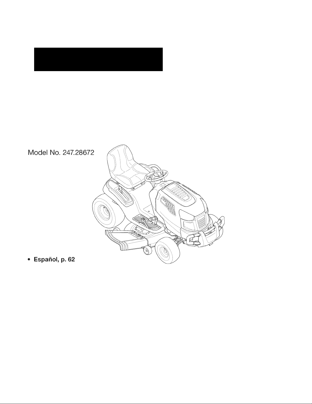
Operator’s Manual
CRRFTSMRN
LAWN TRACTOR
24 HPp 42” Tractor
Electric Start
PYT9000
This product has a low emission engine which operates differently
from previously built engines. Before you start the engine, read and
understand this Operator’s Manual.
IMPORTANT:
Read and follow all Safety
Rules and Instructions before
operating this equipment.
Sears Brands Management Corp., Hoffman Estates, IL 60179 U.S.A.
Visit our website: www.craftsman.com
For answers to your questions about
this product, Call:
1-800-659-5917
Craftsman Tractor Help Line
5am - 5 pm, Mon - Sat
Form No. 769-05910
(February 10,2010)
Page 2

TABLE OF CONTENTS
Warranty Statement
Safety Instructions............................................................3
Safety Labels.........................................................................9
Assembly........................................................................10
Know your Lawn Mower.................................................13
Operation........................................................................16
.........................................................
2
Service and Maintenance ..............................................19
Off-Season Storage
Troubleshooting.............................................................31
Parts List
Español
Service Numbers
........................................................................
..........................................................................
.......................................................
..............................................
30
34
62
Back Oover
WARRANTY STATEMENT
I
CRAFTSMAN PROFESSIONAL FULL WARRANTY
When operated and maintained according to all supplied instructions, if any non-expendable part of this riding equipment fails due to a defect in
material or workmanship within two years from the date or purchase, call 1-800-659-5917 to arrange for free in-home repair.
The frame and front axle will be repaired free of charge for five years from the date of purchase if defective in material or workmanship.
All of the above warranty coverage applies for only one year from the date of purchase if this riding equipment is ever used for commercial or
rental purposes.
In all cases, it repair proves impossible, the riding equipment will be replaced free of charge with the same or an equivalent model.
The battery will be replaced free of charge for 90 days from the date of purchase it defective in material or workmanship (our testing proves that it
will not hold a charge).
This warranty covers ONLY defects in material and workmanship. Sears will NOT pay for:
• Expendable items that become worn during normal use, including but not limited to blades, spark plugs, air cleaners, belts, and oil filters.
• Standard maintenance servicing, oil changes, or tune-ups.
• Tire replacement or repair caused by punctures from outside objects, such as nails, thorns, stumps, or glass.
• Tire or wheel replacement or repair resulting from normal wear, accident, or improper operation or maintenance.
• Repairs necessary because of operator abuse, including but not limited to damage caused by towing objects beyond the capability of the
riding equipment, impacting objects that bend the frame or crankshaft, or over-speeding the engine.
• Repairs necessary because of operator negligence, including but not limited to, electrical and mechanical damage caused by improper
storage, failure to use the proper grade and amount of engine oil, failure to keep the deck clear of flammable debris, or failure to maintain the
riding equipment according to the instructions contained in the operator's manual.
• Engine (fuel system) cleaning or repairs caused by fuel determined to be contaminated or oxidized (stale). In general, fuel should be used
within 30 days of its purchase date.
• Normal deterioration and wear of the exterior finishes, or product label replacement.
This warranty applies only while this product is within the United States.
This warranty gives you specific legal rights, and you may also have other rights which vary from state to state.
Sears, Roebuck and Co., Hoffman Estates, IL 60179
PRODUCT SPECIFICATIONS
Gross HP: 24
Engine Oil: SAE 30
Fuel: Unleaded Gasoline
Spark Plug: Champion® RC12YC
Engine: Briggs & Stratton Professional Series
§ Sears Brands, LLC
Model Number
Serial Number
Date of Purchase.
_
_
Record the model number, serial number,
MODEL NUMBER
and date of purchase above.
Page 3

AWARNING
SAFETY INSTRUCTIONS
A
J
DANGER
This symbol points out important safety instructions which, it not
followed, could endanger the personal safety and/or property of
yourself and others. Read and follow all instructions in this manual
before attempting to operate this machine. Failure to comply with
these instructions may result in personal injury. When you see this
symbol, HEED ITS WARNING!
This machine was built to be operated according to the safe opera
tion practices in this manual. As with any type of power equipment,
carelessness or error on the part of the operator can result in serious
injury. This machine is capable of amputating fingers, hands, toes
and feet and throwing debris. Failure to observe the following safety
instructions could result in serious injury or death.
AWARNING
CALIFORNIA PROPOSITION 65
Engine Exhaust, some of its constituents, and certain vehicle
components contain or emit chemicals known to State of California
to cause cancer and birth defects or other reproductive harm.
Battery posts, terminals, and related accessories contain lead and
lead compounds, chemicals known to the State of California to
cause cancer and reproductive harm. Wash hands after handling.
GENERAL OPERATION
• Read, understand, and follow all instructions on the machine and
in the manual(s) before attempting to assemble and operate.
Keep this manual in a safe place for future and regular reference
and for ordering replacement parts.
• Be familiar with all controls and their proper operation. Know how
to stop the machine and disengage them quickly.
• Never allow children under 14 years old to operate this machine.
Children 14 years old and over should read and understand the
operation instructions and safety rules in this manual and should
be trained and supervised by a parent.
• Never allow adults to operate this machine without proper
instruction.
• To help avoid blade contact or a thrown object injury, keep
bystanders, helpers, children and pets at least 75 feet from the
machine while it is in operation. Stop machine it anyone enters
the area.
• Thoroughly inspect the area where the equipment is to be used.
Remove all stones, sticks, wire, bones, toys, and other foreign
objects which could be picked up and thrown by the blade(s).
Thrown objects can cause serious personal injury.
• Plan your mowing pattern to avoid discharge of material toward
roads, sidewalks, bystanders and the like. Also, avoid discharg
ing material against a wall or obstruction which may cause
discharged material to ricochet back toward the operator.
Your Responsibility—
persons who read, understand and follow the warnings and instruc
tions in this manual and on the machine.
AWARNING
Restrict the use of this power machine to
SAVE THESE INSTRUCTIONS!
Always wear safety glasses or safety goggles during operation
and while performing an adjustment or repair to protect your eyes.
Thrown objects which ricochet can cause serious injury to the
eyes.
Wear sturdy, rough-soled work shoes and close-fitting slacks and
shirts. Loose fitting clothes and jewelry can be caught in movable
parts. Never operate this machine in bare feet or sandals.
Be aware of the mower and attachment discharge direction and
do not point it at anyone. Do not operate the mower without the
discharge cover or entire grass catcher in its proper place.
Do not put hands or feet near rotating parts or under the cutting
deck. Contact with the blade(s) can amputate hands and feet.
A missing or damaged discharge cover can cause blade contact
or thrown object injuries.
Stop the blade(s) when crossing gravel drives, walks, or roads
and while not cutting grass.
Watch tor traffic when operating near or crossing roadways. This
machine is not intended for use on any public roadway.
Do not operate the machine while under the influence of alcohol
or drugs.
Mow only In daylight or good artificial light.
Never carry passengers.
Disengage blade(s) before shifting into reverse. Back up slowly.
Always look down and behind before and while backing to avoid a
back-over accident.
Page 4

SAFETY INSTRUCTION
I
Slow down before
erratic operation and excessive speed.
Disengage blade(s), set parking brake, stop engine and wait until
the blade(s) come to a complete stop before removing grass
catcher, emptying grass, unclogging chute, removing any grass or
debris, or making any adjustments.
Never leave a running machine unattended. Always
blade(s), set parking brake, stop engine and remove key before
dismounting.
Use extra care when loading or unloading the machine into a
trailer or truck. This machine should not be driven up or down
ramp(s), because the machine could tip over, causing serious
personal injury. The machine must be pushed manually on
ramp(s) to load or unload properly.
Muffler and engine become hot and can cause a burn. Do not
touch.
Check overhead clearances carefully before driving under low
hanging tree branches, wires, door openings etc., where the
operator may be struck or pulled from the machine, which could
result in serious injury.
Disengage all attachment clutches and depress the brake pedal
completely before attempting to start engine.
Your machine is designed to cut normal residential grass of a
height no more than 10”. Do not attempt to mow through unusually
tall, dry grass (e.g., pasture) or piles of dry leaves. Dry grass or
leaves may contact the engine exhaust and/or build up on the
mower deck presenting a potential
Use only accessories and attachments approved for this machine
by the machine manufacturer. Read, understand and follow all
instructions provided with the approved accessory or attachment.
Fora list of approved accessories and attachments, call 1-800
659-5917.
Data indicates that operators, age 60 years and above, are
involved in a large percentage of riding mower-related injuries.
These operators should evaluate their ability to operate the riding
mower safely enough to protect themselves and others from
serious injury.
If situations occur which are not covered in this manual, use care
and good judgment. Contact 1-800-659-5917 for information and
assistance.
turning.
Operate the machine smoothly. Avoid
turn
off
fire
hazard.
SLOPE OPERATION
Slopes are a major factor related to loss of control and tip-over
accidents which can result in severe injury or death. All slopes require
extra caution. If you cannot back up the slope or it you feel uneasy on
it, do not mow it.
For your safety, use the Slope Guide included as part of this manual
to measure slopes before operating this machine on a sloped or hilly
area. If the slope is greater than 15 degrees as shown on the Slope
Guide, do not operate this machine on that area or serious injury could
result.
Do:
• Mow up and down slopes, not across. Exercise extreme caution
when changing direction on slopes.
• Watch tor holes, ruts, bumps, rocks, or other hidden objects.
Uneven terrain could overturn the machine. Tall grass can hide
obstacles.
• Use slow speed. Choose a low enough speed setting so that
you will not have to stop or shift while on the slope. Tires may
lose traction on slopes even though the brakes are functioning
properly. Always keep machine in gear when going down slopes
to take advantage of engine braking action.
• Follow the manufacturer’s recommendations for wheel weights
or counterweights to improve stability. For recommendations, call
1-800-659-5917.
• Use extra care with grass catchers or other attachments. These
can change the stability of the machine.
• Keep all movement on the slopes slow and gradual. Do not make
sudden changes in speed or direction. Rapid engagement or
braking could cause the front of the machine to lift and rapidly flip
over backwards which could cause serious injury.
• Avoid starting or stopping on a slope. If tires lose traction, disen
gage the blade(s) and proceed slowly straight down the slope.
Do Not:
• Do not turn on slopes unless necessary; then, turn slowly and
gradually downhill, if possible.
• Do not mow near drop-offs, ditches or embankments. The mower
could suddenly
ditch, or it an edge caves in.
• Do not try to stabilize the machine by putting your foot on the
ground.
• Do not use a grass catcher on steep slopes.
• Do not mow on wet grass. Reduced traction could cause sliding.
• Do not attempt to coast downhill. Over-speeding may cause the
operator to lose control of the machine resulting in serious injury
or death.
• Do not tow heavy pull behind attachments (e.g. loaded dump cart,
lawn roller, etc.) on slopes greater than 5 degrees. When going
down hill, the extra weight tends to push the tractor and may
cause you to loose control (e.g. tractor may speed up, braking and
steering ability are reduced, attachment may jack-knife and cause
tractor to overturn).
turn
over if a wheel is over the edge of a cliff,
Page 5

SAFETY INSTRUCTIONS
J
CHILDREN
Tragic accidents can occur it the operator is not alert to the presence
of children. Children are often attracted to the machine and the mowing
activity. They do not understand the dangers. Never assume that
children will remain where you last saw them.
• Keep children out of the mowing area and In watchful care of a
responsible adult other than the operator.
• Be alert and turn machine off if a child enters the area.
• Before and while backing, look behind and down for small
children.
• Never carry children, even with the blade(s) shut off. They may
fall off and be seriously Injured or Interfere with safe machine
operation.
• Use extreme care when approaching blind corners, doorways,
shrubs, trees or other objects that may block your vision of a child
who may run Into the machine.
• To avoid back-over accidents, always disengage the cutting
blade(s) before shifting Into Reverse. If equipped, the “Reverse
Caution Mode” (blades operate while machine rides in reverse)
should not be used when children or others are around.
• Keep children away from hot or running engines. They can suffer
bums from a hot muffler.
• Remove key when machine Is unattended to prevent unauthorized
operation.
Never allow children under 14 years of age to operate this machine.
Children 14 and over should read and understand the Instructions and
safe operation practices In this manual and on the machine and should
be trained and supervised by an adult.
TOWING
• Tow only with a machine that has a hitch designed for towing. Do
not attach towed equipment except at the hitch point.
• Follow the manufacturers recommendation for weight limits tor
towed equipment and towing on slopes. For recommendations,
call 1-800-659-5917.
• Never allow children or others In or on towed equipment.
• On slopes, the weight of the towed equipment may cause loss of
traction and loss of control.
• Always use extra caution when towing with a machine capable of
making tight turns (e.g. “zero-turn” ride-on mower). Make wide
turns to avoid jack-knifing.
• Travel slowly and allow extra distance to stop.
• Do not coast downhill.
SERVICE
Safe
Handling of Gasoline
To avoid personal injury or property damage use extreme care in
handling gasoline. Gasoline is extremely flammable and the vapors are
explosive. Serious personal injury can occur when gasoline is spilled
on yourself or your clothes which can ignite. Wash your skin and
change clothes immediately.
• Use only an approved gasoline container.
• Never fill containers inside a vehicle or on a truck or trailer bed
with a plastic liner. Always place containers on the ground away
from your vehicle before filling.
• When practical, remove gas-powered equipment from the truck
or trailer and refuel it on the ground. If this is not possible, then
refuel such equipment on a trailer with a portable container, rather
than from a gasoline dispenser nozzle.
• Keep the nozzle in contact with the rim of the fuel tank or
container opening at all times until fueling is complete. Do not use
a nozzle lock-open device.
• Extinguish all cigarettes, cigars, pipes and other sources of
ignition.
• Never fuel machine indoors.
• Never remove gas cap or add fuel while the engine is hot or run
ning. Allow engine to cool at least two minutes before refueling.
• Never over fill fuel tank. Fill tank to no more than
bottom of filler neck to allow space for fuel expansion.
• Replace gasoline cap and tighten securely.
• If gasoline is spilled, wipe it off the engine and equipment. Move
machine to another area. Wait 5 minutes before starting the
engine.
• To reduce fire hazards, keep machine free of grass, leaves, or
other debris build-up. Clean up oil or fuel spillage and remove any
fuel soaked debris.
• Never store the machine or fuel container inside where there is an
open flame, spark or pilot light as on a water heater, space heater,
furnace, clothes dryer or other gas appliances.
• Allow a machine to cool at least five minutes before storing.
Vi
inch below
Page 6

SAFETY INSTRUCTION
I
General Service
• Never
• Before cleaning, repairing, or inspecting, make certain the
• Periodically check to make sure the blades come to complete
• Check brake operation frequently as It Is subjected to wear during
• Check the blade(s) and engine mounting bolts at frequent
• Mower blades are sharp. Wrap the blade or wear gloves, and use
• Keep all nuts, bolts, and screws tight to be sure the equipment Is
• Never tamper with the safety interlock system or other safety
• After striking a foreign object, stop the engine, disconnect the
• Never attempt to make adjustments or repairs to the machine
• Grass catcher components and the discharge cover are subject
run
an engine indoors or in a poorly ventilated area. Engine
exhaust contains carbon monoxide, an odorless, and deadly gas.
blade(s) and all moving parts have stopped. Disconnect the spark
plug wire and ground against the engine to prevent unintended
starting.
stop within approximately (5) five seconds after operating the
blade disengagement control. If the blades do not stop within the
this time frame, your machine should be serviced professionally
by a Sears or other qualified service dealer.
normal operation. Adjust and service as required.
Intervals for proper tightness. Also, visually Inspect blade(s)
for damage (e.g., excessive wear, bent, cracked). Replace the
blade(s) with the original equipment manufacturer’s (O.E.M.)
blade(s) only, listed In this manual. Use of parts which do not
meet the original equipment specifications may lead to Improper
performance and compromise safety!
extra caution when servicing them.
In safe working condition.
devices. Check their proper operation regularly.
spark plug wire(s) and ground against the engine. Thoroughly
Inspect the machine for any damage. Repair the damage before
starting and operating.
while the engine is running.
to wear and damage which could expose moving parts or allow
objects to be thrown. For safety protection, frequently check
components and replace immediately with original equipment
manufacturer's (O.E.M.) parts only, listed In this manual. Use of
parts which do not meet the original equipment specifications may
lead to Improper performance and compromise safety!
• Do not change the engine governor settings or over-speed the
engine. The governor controls the maximum safe operating speed
of the engine.
• Maintain or replace safety and instruction labels, as necessary.
• Observe proper disposal laws and regulations for gas, oil, etc. to
protect the environment.
• According to the Consumer Products Safety Commission (CPSC)
and the U.S. Environmental Protection Agency (EPA), this product
has an Average Useful Life of seven (7) years, or 270 hours
of operation. At the end of the Average Useful Life, buy a new
machine or have the machine inspected annually by a Sears or
other qualified service dealer to ensure that all mechanical and
safety systems are working properly and not worn excessively.
Failure to do so can result In accidents, injuries or death.
DO NOT MODIFY ENGINE
To avoid serious injury or death, do not modify engine in any way.
Tampering with the governor setting can lead to a runaway engine and
cause it to operate at unsafe speeds. Never tamper with factory setting
of engine governor.
NOTICE REGARDING EMISSIONS
Engines which are certified to comply with California and federal
EPA emission regulations for SCRE (Small Cff Road Equipment) are
certified to operate on regular unleaded gasoline, and may include
the following emission control systems: Engine Modification (EM) and
Three Way Catalyst (TWC) If so equipped.
SPARK ARRESTOR
This machine is equipped with an internal combustion engine and
should not be used on or near any unimproved forest-covered,
brushcovered or grass-covered land unless the engine's exhaust
system Is equipped with a spark arrester meeting applicable local or
state laws (If any).
If a spark arrester Is used, it should be maintained in effective working
order by the operator. In the State of California the above is required
by law (Section 4442 of the California Public Resources Code). Cther
states may have similar laws. Federal laws apply on federal lands.
A spark arrester for the muffler is available through your nearest Sears
Parts and Repair Service Center.
AWARNING
Page 7

SAFETY INSTRUCTIONS
SAFETY SYMBOLS
This page depicts
before attempting to assemble and operate.
and
describes safety symbols that may appear
Symbol Description
on
this product. Read, understand, and follow all instructions on the machine
J
r
READ THE OPERATOR’S MANUAL(S)
Read, understand, and followall instructions in the manual(s) before attempting to assemble and
operate
DANGER— ROTATING BLADES
Never carry passengers. Never carry children, even with the blades off.
DANGER— ROTATING BLADES
Always look down and behind before and while backing to avoid a back-over accident.
WARNING— ROTATING BLADES
Do not put hands or feet near rotating parts or under the cutting deck. Contact with the blade(s)
can amputate hands and feet.
WARNING—THROWN OBJECTS
This machine may pick up and throw and objects which can cause serious personal injury.
WARNING—THROWN OBJECTS
This machine may pick up and throw and objects which can cause serious personal injury.
1#
BYSTANDERS
Keep bystanders, helpers, children and pets at least 75 feet from the machine while it is in
operation.
WARNING— SLOPE OPERATION
Do not operate this machine on a slope greater than 15 degrees.
WARNING—HOT SURFACE
Engine parts, especially the muffler, become extremely hot during operation. Allow engine and
muffler to cool before touching.
DANGER — ROTATING BLADES
To reduce the risk of injury, keep hands and feet away. Do not operate unless discharge cover or grass
catcher is in its proper place. If damaged, replace immediately.
Page 8
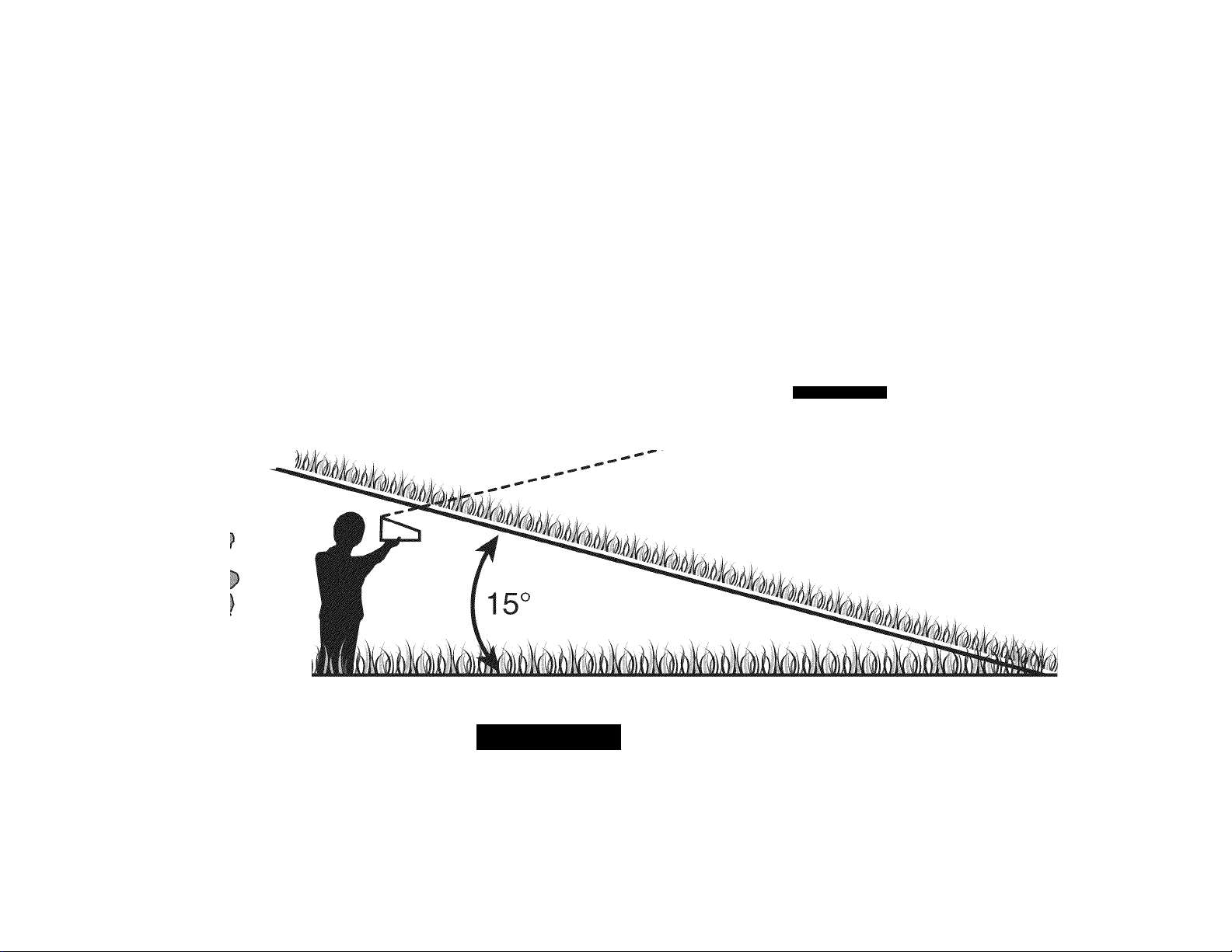
Sight
and hold this level with a vertical tree...
or a corner of a building...
--------or a fence post
m
f-
o
T3
m
O
c
D
m
f-Oslmk
Fole)
aion.
■'.'I.. II. .'r'lfy.
A WARNING
Use this page as a guide to determine slopes where you may not operate safely.
Do not operate your lawn mower on such slopes. Do not mow on inclines with a slope in excess of 15 degrees (a rise of approximately 2-1/2 feet every 10 feet). A riding
mower could overturn and cause serious injury. Operate riding mowers up and down slopes, never across the face of slopes.
Page 9
, A danger
^AVO IO SERIOUS INJURY OR
?5i^<^TS THAT CAN BE THROW«
. nn. " direction, wear SAFETT GUSbW
te^iDiy WHEN CHILDREN OR OTHERS ARE №0"®'
KEEP HANDS AND FEET AWAY.
DO NOT OPERATE MOWER
UNLESS CHUTE DEFLECTOR
OR ENTIRE CRASS CATCHER IS
ASSEMBLE CHUTE DEFLECTOR TO THIS UNIT BEFORE OPERATING.
IN ITS PROPER PLACE.
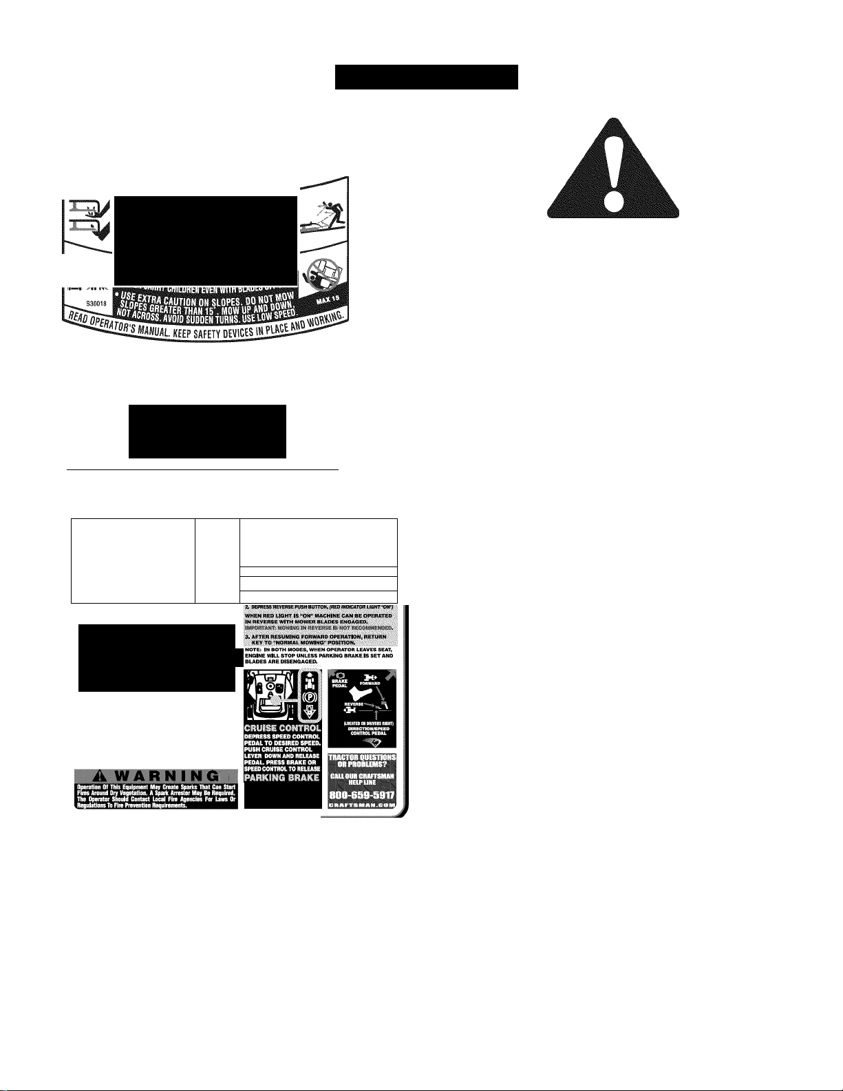
SAFETY LABEL
J
WARNING
This symbol points out important safety instructions
which, if not followed, could endanger the personal
safety and/or property of yourself and others. Read and
follow all instructions in this manual before attempting
to operate this machine. Failure to comply with these
instructions may result in personal injury. When you see
this symbol HEED ITS WARNING!
Your Responsibility
Restrict the use of this power machine to persons who
read, understand, and follow the warnings and instruc
tions in this manual and on the machine.
ROTATING BLADES CAUSE
SERIOUS INJURY OR DEATH
• DO NOT MOW WIHN ONLOREN OTHERS ARE
• Him CA№iY CHADREN EVEN WITK BLADEfS) №F.
4.
■3^
WARN
TO AVOID SERIOUS INJURY OR DEATH
eo UP ANO DOWN SLOPES, NOT AQIOSS.
AVOID SUHIEN TURNS.
DO mr OPBUTTE THE UNIT WHERE IT COULD SLIP OR TIP.
IF MACHINE STOPS IHIIIffi UPHILL, STOP BLADE(S}
AND BACK MWNHIi. SLOWLY.
KSP SAFETY DEVICE (IHJARDS, SHIELDS, AND
SWITCHES, ETC.) IN PUCE AMD WOMOI^.
1. MSENGACE BUKKFTO, fPOWffl TAKE
2. »«GAGE THE TRACTORS MRKWG BRAKE.
3. ACTIVATE THE CH№(E C№rnT0L
4.1WI KEY TO STMT EHGM. AFTER STMT RaEASE KEY & ^ACTIVATE »OKE
BY nJlCWG THROTTU TO FAST -nABBir POSITIOIL
ijy. 'Mi’v;,'.
YOU MUST DISENGAGE DLADES/PTO, (POWEF TAKE OFF!
BEFORE TRAVELING IN REVERSE.
DEPRESS BRAKE PEDAL,
miSH PARKING BRAKE
LEVER DOWN AND
RELEASE PEDAL 10 LOCK
Page 10
ASSEMBLY
TRACTOR SET-UP
Shipping Brace Removal
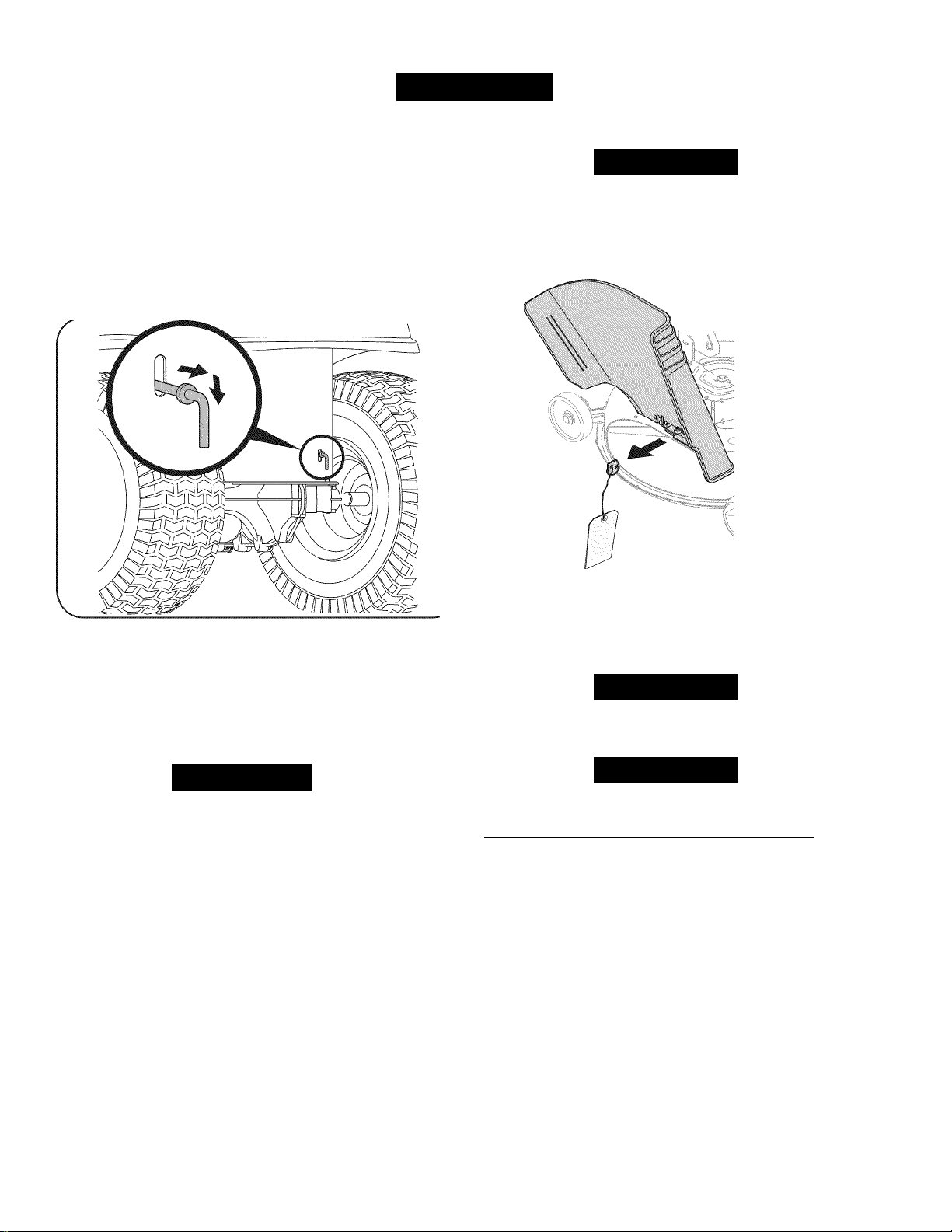
Moving The Tractor Manually
Your tractor’s transmission is equipped with a hydrostatic relief valve
for occasions when it is necessary to move the tractor manually. Open
ing this valve permits the fluid in the transmission to bypass its normal
route, allowing the rear tires to “freewheel.” To open the hydrostatic
relief valve, proceed as follows:
1. Locate the hydrostatic bypass rod in the rear of the tractor. See
Figure 1.
Make sure the lawn tractor’s engine is off, set the parking brake and
remove the ignition key before removing the shipping brace.
1. Locate the shipping brace, it present, and warning tag found on
the right side of the cutting deck. See Figure 2.
AWARNING
Figure 1
2. Pull the hydrostatic bypass rod outward, then down, to lock it in
place.
NOTE:
bypass rod is pulled out. Return the rod to its normal position prior to
operating the tractor.
Never attempt to move the tractor manually without first opening the
hydrostatic relief valve. Doing so will result in serious damage to the
tractor’s transmission.
The transmission will NOT engage when the hydrostatic
A
CAUTION
2. While holding the discharge chute cover with your left hand,
The shipping brace is used for packaging purposes only. Remove
and discard the shipping brace before operating your lawn tractor.
The mowing deck is capable of throwing objects. Operating the riding
mower without the discharge cover in the proper operating position
could result
Figure 2
remove the shipping brace with your right hand by grasping it
between your thumb and index finger and rotating it clockwise.
AWARNING
AWARNING
in
serious personal injury and/or property damage.
10
Page 11
ASSEMBLY
J
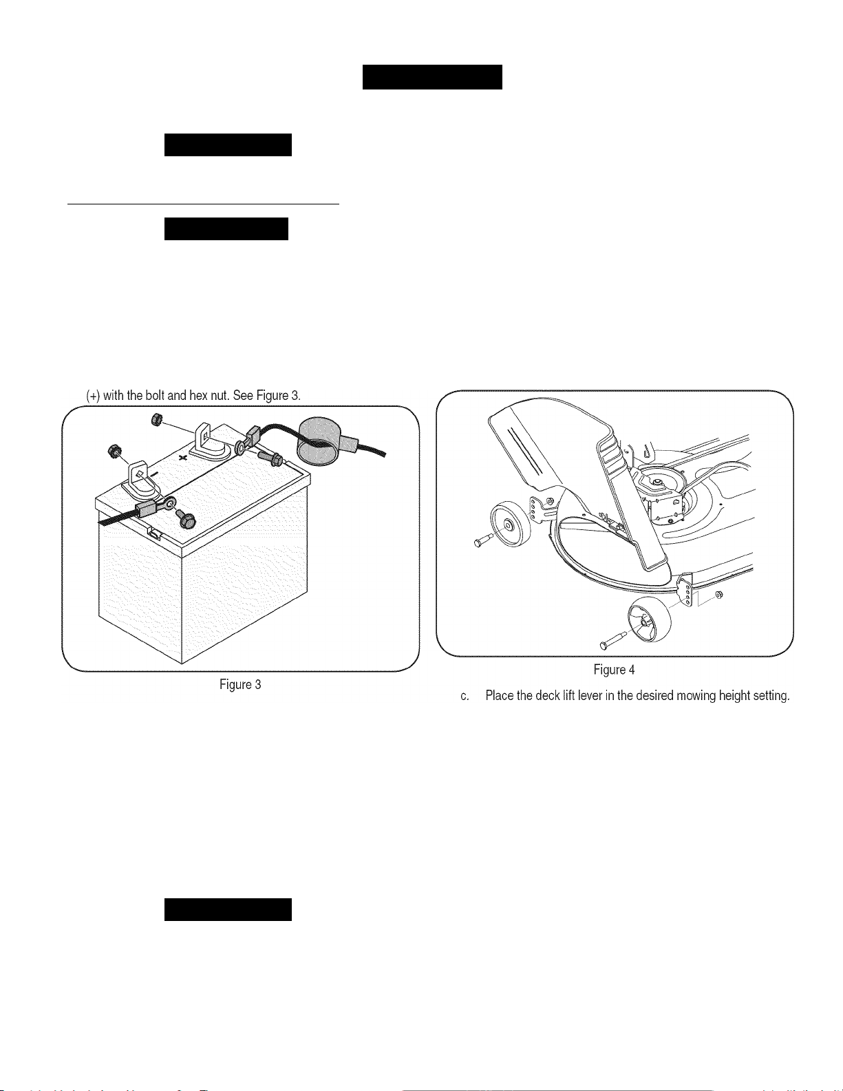
CONNECTING THE BATTERY CABLES
Awarning
Battery posts, terminals, and related accessories contain lead and
lead compounds, chemicals known to the State of California to cause
cancer and reproductive harm. Wash hands after handling.
__________
A CAUTION
When attaching battery cables, always connect the POSITIVE (Red)
wire to its terminal first, followed by the NEGATIVE (Black) wire.
To connect the battery cables, proceed as follows:
NOTE:
battery terminal is marked Neg. (-).
The positive battery terminal is marked Pos. (+). The negative
1. Remove the plastic cover, it present, from the positive (+) battery
terminal and attach the red cable to the positive battery terminal
Setting the Deck Gauge Wheels
Move the tractor on a firm and level surface, preferably pavement, and
proceed as follows:
1. Select the height position of the cutting deck by placing the deck
2. Check the gauge wheels for contact or excessive clearance with
If the gauge wheels have excessive clearance or contact with the
surface, adjust as follows:
lift lever in the normally desired mowing height setting (any of the
six different cutting height notches on the right fender).
the surface below. The deck gauge wheels should have between
Va”
and
y-i
clearance above the ground.
a. Raise the deck lift handle to its highest setting.
b. Remove the front and rear gauge wheels by removing the
lock nuts and shoulder screws which secure them to the
deck. See Figure 4.
2. Remove the plastic cover, if present, from the negative (-) battery
terminal and attach the black cable to the negative battery
terminal (-) with the bolt and hex nut. See Figure 3.
3. Position the red rubber boot over the positive battery terminal to
help protect it from corrosion.
NOTE:
side of battery, charge the battery as instructed in the Service and
Maintenance section of this Operator’s Manual prior to operating the
tractor.
If the battery is put into service after the date shown on top/
Refer to Leveling the Deck in the Service and Maintenance section
of this manual for more detailed instructions regarding various deck
adjustments.
Checking Tire Pressure
Awarning
Do not overinflate tires. Check sidewall of tires for maximum psi.
Equal tire pressure should be maintained at all times.
The tires on your tractor may be over inflated for shipping purposes.
Reduce the tire pressure before operating the tractor. Check sidewall
of tires for maximum psI.
11
d. Reinsert the shoulder screw (with each gauge wheel) into
the index hole that leaves approximately
bottom of the wheel and the pavement.
Vi'
between the
Page 12
ASSEMBL
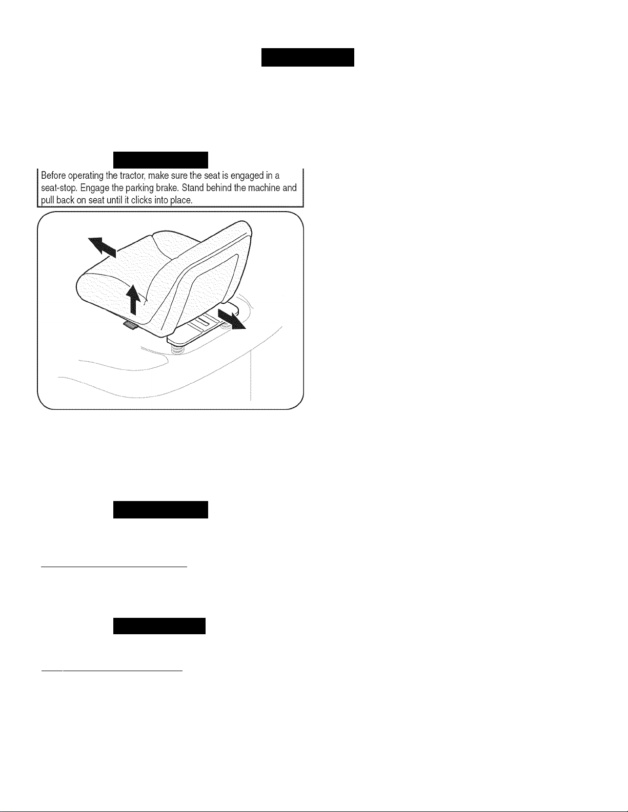
Adjusting the Seat
To adjust the position of the seat, pull up
lever. Slide the seat forward or rearward to the desired position; then
release the adjustment lever Make sure seat is locked into position in
a seat-stop before operating the tractor See Figure 5.
AWARNING
and
hold the seat adjustment
J
Figure 5
Gas and Oil
The fuel tank is located under the hood and has a capacity of two
gallons. Remove the fuel cap by turning it counterclockwise. Use only
clean, fresh (no more than 30 days old), unleaded gasoline. Stop filling
tank once fuel is seen inside the filler neck. Do not overfill the tank.
AWARNING
Use extreme care when handling gasoline. Gasoline is extremely
flammable and the vapors are explosive. Never fuel the machine
indoors or while the engine is hot or running. Extinguish cigarettes,
cigars, pipes and other sources of ignition.
NOTE:
MUST check the oil level before operating. See Checking the Engine
Oil in the Service and Maintenance section of this manual.
Your tractor is shipped with oil in the engine. Flowever, you
___________________
A CAUTION
Always check the engine oil level before each use as instructed in
the Maintenance section. Add oil as necessary. Failure to do so may
result
in
serious damage to your engine.
_____________________
12
Page 13
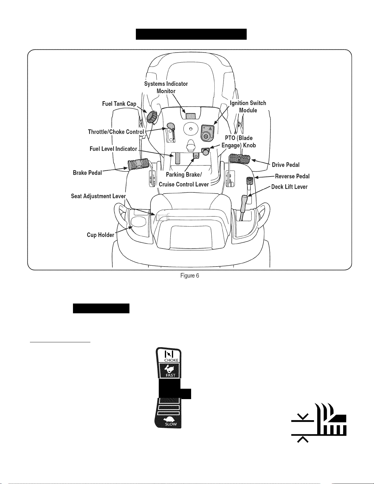
KNOW YOUR MOWER
Lawn Tractor controls and features are illustrated in Figure 6 and
described on the following pages.
AWARNING
Read and follow all safety rules and instructions in this manual,
including the entire Operation section, before attempting to operate
this machine. Failure to comply with all safety rules and instructions
may result
THROTTLE/CHOKE CONTROL
The throttle/choke control is located on the left side of
the tractor’s dash panel. This lever controls the speed
of the engine and, when pushed all the way forward,
closes the choke for cold starting. When set in a given
position, the throttle will maintain a uniform engine
speed.
NOTE:
deck engaged, be certain that the throttle/choke
control is always in the FAST (rabbit) position.
in
personal injury.
When operating the tractor with the cutting
___________________________
□
IZZI
BRAKE PEDAL
The brake pedal is located on the left front
side of the tractor along the running board.
The brake pedal can be used for sudden
stops or setting the parking brake.
NOTE:
depressed to activate the safety interlock
switch when starting the tractor.
SEAT ADJUSTMENT LEVER
The seat adjustment lever is located below the front/left of the seat.
The lever allows for adjustment of the fore to aft position of the
operator's seat. Refer to the Assembly section of this manual for more
detailed instructions.
DECK LIFT LEVER
Found on your tractor’s right fender,
the deck lift lever is used to change the
height of the cutting deck. To use, move
the lever to the left, then place in the
notch best suited for your application.
The brake pedal must be fully
(O)
13
Page 14
KNOW YOUR MOWER
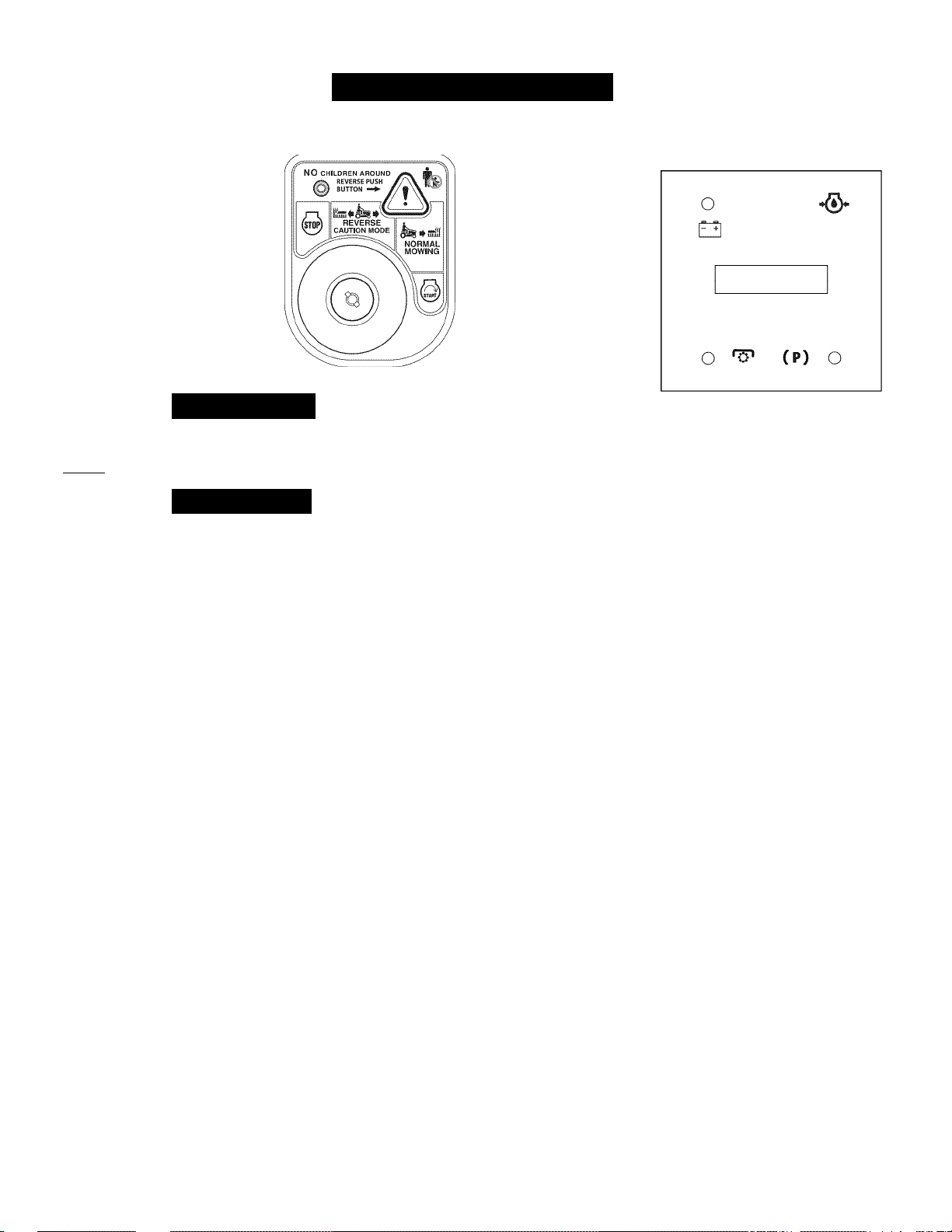
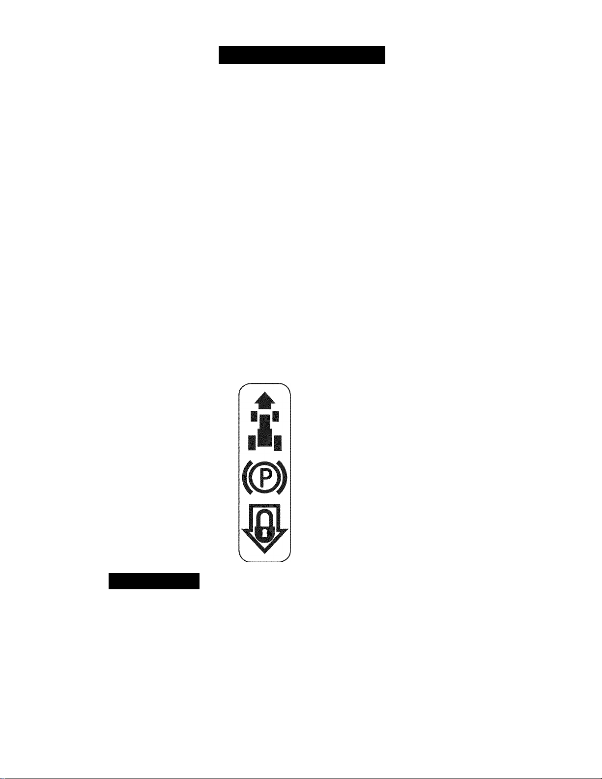
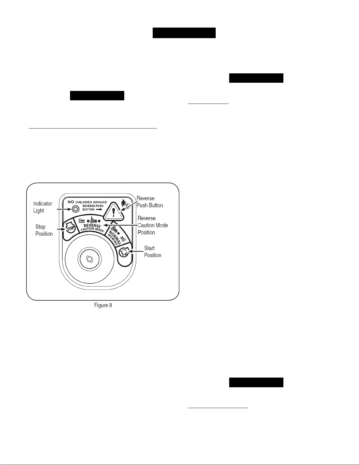
IGNITION SWITCH MODULE
To start the engine, insert the key into
the ignition switch and turn clockwise
to the START position. Release the
key into the NORMAL MOWING MODE
position once the engine has fired.
To stop the engine, turn the ignition key
counterclockwise to the STOP position.
Awarning
Never leave a running machine unattended. Always disengage PTO,
set parking brake, stop engine and remove key to prevent unintended
starting.___________________________________________
A CAUTION
Prior to operating the tractor, refer to both Safety Interlock Switches and
Starting The Engine in the Operation section of this manual for detailed
instructions regarding the Ignition Switch Module and operating the
tractor in REVERSE CAUTION MODE.
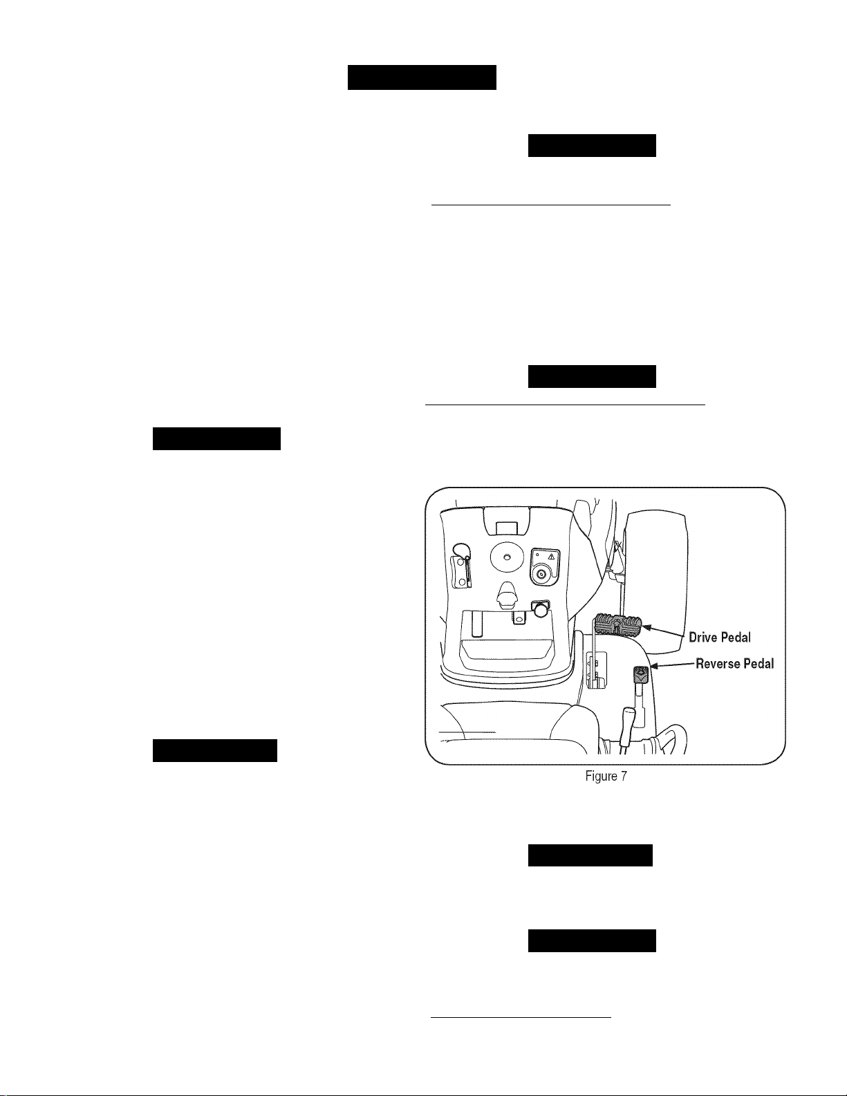
DRIVE PEDAL
The drive pedal is located on the right side of the
tractor, along the running board. Press the drive
pedal forward to cause the tractor to travel forward.
Ground speed is also controlled with the drive pedal.
The further forward that the pedal is pivoted, the
faster the tractor will travel. The pedal will return to
its original position when it's not pressed.
T
lil
REVERSE PEDAL
The reverse pedal is located on the right side of the
tractor along the running board. Ground speed is
also controlled with the reverse pedal. The further
downward the pedal is pivoted, the faster the
tractor will travel. The pedal will return to its original
position when it's not pressed.
Ï"
lll
«
SYSTEMS INDICATOR MONITOR/HOUR METER LCD
When the ignition key is
rotated out of the STOP
position but not into the START
position, the system's indicator
monitor displays the battery's
output, in volts, on its LCD for
approximately five seconds,
after which it displays an hour
glass and the hours of tractor
operation. Once the tractor is
started, the monitor continually
displays an hourglass and the
hours of tractor operation on its LCD.
NOTE:
key is rotated out of the STOP position, regardless of whether the
engine is started.
The Indicator Monitor will also remind the operator of maintenance
intervals for changing the engine oil. The LCD will alternately flash
the recorded hours, “CHG” and “OIL” tor five minutes, after every 50
hours of recorded operation elapse. The maintenance interval lasts
for two hours (from 50-52, 100-102, 150-152, etc.). The LCD will also
flash as described above for five minutes every time the tractor's
engine has been started during this maintenance interval. Before the
interval expires, change the engine oil as instructed in the Service and
Maintenance section of this Operator's Manual.
Brake
If the Brake light illuminates when attempting to start the tractor's
engine, depress the brake pedal.
PTO (Blade Engage)
If the PTO light illuminates when attempting to start the tractor's
engine, move PTO knob into the disengaged (OFF) position.
Oil
It is normal for the Oil light to illuminate while the engine is cranking
during start-up, but if it illuminates during operation, while the engine is
running, stop the tractor immediately and check the engine oil level as
instructed in this Operator's Manual.
Battery
It is normal for the Battery light to illuminate while the engine is
cranking during start-up, but if it illuminates during operation, while the
engine is running, the battery is in need of a charge or the engine's
charging system is not generating sufficient amperage. Charge the
battery as instructed in the Service section of this manual or have the
charging system checked by a Sears or other qualified service dealer.
Hours of tractor operation are recorded any time the ignition
14
Page 15
KNOW YOUR MOWE
FUEL LEVEL INDICATOR
The Fuel Level Indicator Is located
dash and Indicates the amount of fuel In the gas tank.
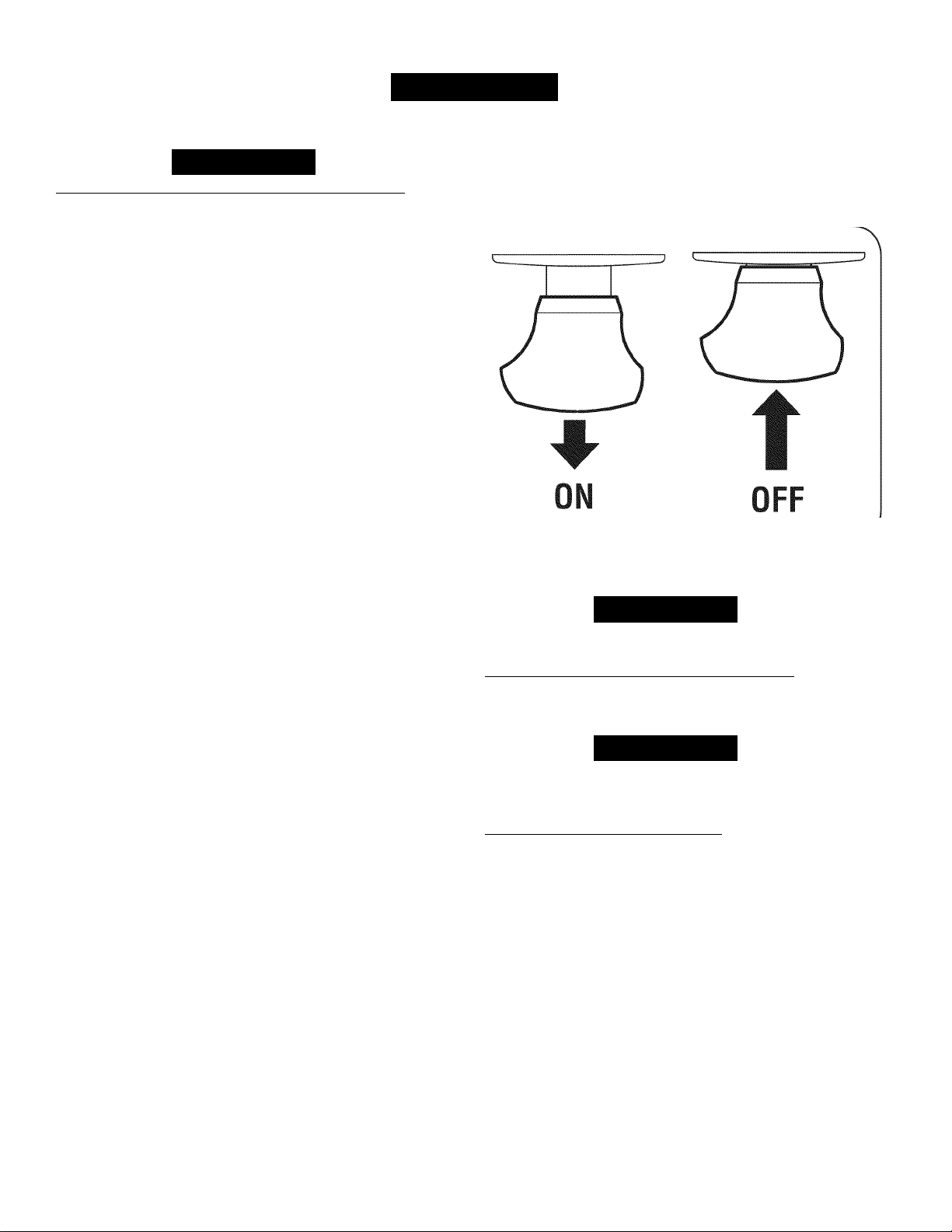
PTO/BLADE ENGAGE KNOB
Activating the PTO engages power to the
cutting deck or other (separately available)
attachments. Pull outward on the PTO/Blade
Engage knob to activate it. Push the PTO/
Blade Engage knob inward to disengage the
power to the cutting deck or other (separately
available) attachments.
NOTE:
be in the disengaged (OFF) position when
starting the engine.
The PTO/Blade Engage knob must
on
the left side of the tractor’s
PTO
S
O I
OFF ON
furi
J
*
o
PARKING BRAKE/CRUISE CON
TROL LEVER
Located in the center of the tractor’s dash panel below
the steering wheel, the Parking Brake/Cruise Control
lever is used to engage the parking brake and the cruise
control Refer to the Operation section of this manual for
detailed instructions regarding the parking brake.
NOTE:
leaves the seat with the engine running or the engine
will automatically shut off.
NOTE:
tractor’s fastest ground speed. If the operator should
attempt to do so, the tractor will automatically decelerate
to the fastest optimal mowing ground speed.
The parking brake must be set it the operator
Cruise control can NOT be engaged at the
AWARNING
Never leave a running machine unattended. Always disengage PTO
(Blade Engage knob), set parking brake, stop engine and remove key
to prevent unintended starting.
15
Page 16
OPERATION
SAFETY INTERLOCK SWITCHES
This tractor is equipped with a safety interlock system for the protection
of the operator. If the interlock system should ever malfunction, do not
operate the tractor. Contact a Sears or other qualified service dealer.
• The safety interlock system prevents the engine from cranking or
starting unless the parking brake is engaged, and the PTO (Blade
Engage) handle is in the disengaged (OFF) position.
• The engine will automatically shut off if the operator leaves the
seat before engaging the parking brake.
• The electric PTO (Blade Engage) clutch will automatically shut
off if the operator leaves the tractor's seat with the PTO (Blade
Engage) knob in the engaged (ON) position, regardless of
whether the parking brake is engaged.
• With the ignition key in the NORMAL MOWING position, the
electric PTO (Blade Engage) clutch will automatically shut off if
the PTO (Blade Engage) knob is moved into the engaged (ON)
position with the drive pedal in position for reverse travel.
Awarning
Do not operate the tractor if the interlock system is malfunctioning.
This system was designed for your safety and protection.
STOPPING THE ENGINE
If you strike a foreign object, stop the engine and disconnect the
spark plug wire(s). Thoroughly inspect the machine for any damage.
Repair the damage before restarting and operating.
If the blades are engaged, place the PTO/Blade Engage knob in
the disengaged (OFF) position.
Place the throttle control near the SLOW position.
Turn the ignition key counterclockwise to the STOP position.
Remove the key from the ignition switch to prevent unintended
starting.
DRIVING THE TRACTOR
I
Avoid sudden starts, excessive speed and sudden stops.
Lightly press the brake pedal to release the parking brake. Move the
throttle lever into the FAST (rabbit) position.
1. To travel FORWARD, slowly press the drive pedal forward until
the desired speed is achieved. See Figure 7.
STARTING THE ENGINE
NOTE:
Gasoline and Oil fill-up instructions.
Refer to the Assembly & Set-Up section of this manual for
Awarning
______________
AWARNING
_________
1. Insert the tractor key into the ignition switch module.
2. Place the PTO (Blade Engage) knob in the disengaged (OFF)
position.
3. Engage the tractor’s parking brake.
4. Activate the choke control by moving the throttle/choke control all
the way forward into the choke position.
5. Turn the ignition key clockwise to the START position. After
the engine starts, release the key. It will return to the NORMAL
MOWING position.
A CAUTION
Do NOT hold the key in the START position for longer than ten
seconds at a time. Doing so may cause damage to your engine’s
electric starter.
6. After the engine starts, deactivate the choke control.
NOTE:
Doing so will result in a “rich” fuel mixture and cause the engine to run
poorly.
Do NOT leave the choke control on while operating the tractor.
Do NOT attempt to change the direction of travel when the tractor is
in motion. Always bring the tractor to a complete stop before moving
from forward to reverse or vice versa.
Do not leave the seat of the tractor without first placing the PTO/
Blade Engage knob in the disengaged (OFF) position and engaging
the parking brake. If leaving the tractor unattended, also turn the
engine off and remove the ignition key.
To travel in REVERSE, check that the area behind is clear then
slowly depress the reverse pedal with the ball of your foot (NOT
your heel) until the desired speed is achieved. See Figure 7.
A CAUTION
AWARNING
16
Page 17
OPERATION
J
REVERSE CAUTION MODE
The REVERSE CAUTION MODE position of the key switch module
allows the tractor to be operated
engaged.
NOTE:
Mowing in reverse is not recommended.
in
reverse with the blades (PTO)
AWARNING
Use extreme caution while operating the tractor in the REVERSE
CAUTION MODE. Always look down and behind before and while
backing. Do not operate the tractor when children or others are
around. Stop the tractor immediately
To use the REVERSE CAUTION MODE:
NOTE:
1. Start the engine as previously instructed on the previous page.
2. Turn the key from the NORMAL MOWING (Green) position to the
The operator MUST be seated in the tractor seat.
REVERSE CAUTION MODE (Yellow) position of the key switch
module. See Figure 8.
if
someone enters the area.
DRIVING ON SLOPES
Refer to the SLOPE GUIDE on page 8 to help determine slopes where
you may operate the tractor safely.
Do not mow on inclines with a slope in excess of 15 degrees (a rise of
approximately 2-1/2 feet every 10 feet). The tractor could overturn anc
cause serious injury.
• Mow up and down slopes, NEVER across.
• Exercise extreme caution when changing direction on slopes.
• Watch for holes, ruts, bumps, rocks, or other hidden objects.
• Avoid turns when driving on a slope. If a turn must be made, turn
• Avoid stopping when driving up a slope. If it is necessary to stop
ENGAGING THE PARKING BRAKE/SETTING THE CRUISE CONTROL
NOTE:
same lever. If using the brake when engaging the parking brake/
cruise control lever, the parking brake will engage. If using the drive
pedal when engaging the parking brake/cruise control lever, the cruise
control will engage.
AWARNING
_________________________________
Uneven terrain could overturn the machine. Tall grass can hide
obstacles.
down the slope. Turning up a slope greatly increases the chance
of a roll over.
while driving up a slope, start up smoothly and carefully to reduce
the possibility of flipping the tractor over backward.
The parking break and cruise control are controlled by the
Parking Brake
NOTE:
with the engine running or the engine will automatically shut off.
To set the parking brake:
1. Press the brake pedal completely down with your left foot and
hold it in that position.
3. Press the REVERSE PUSH BUTTON (Orange, Triangular Button)
at the top, right corner of the key switch module. The red indicator
light at the top, left corner of the key switch module will be ON
while activated. See Figure 8.
4. Once activated (indicator light ON), the tractor can be driven in
reverse with the cutting blades (PTO) engaged.
5. Always look down and behind before and while backing to make
sure no children are around. After resuming forward motion,
return the key to the NORMAL MOWING position.
The REVERSE CAUTION MODE will remain activated until:
a. The key is placed in either the NORMAL MOWING position
or STOP position or
b. The operator leaves the seat.
2. Push the parking brake/cruise control lever downward and hold it
in that position.
3. Remove your foot from the brake pedal.
4. Release pressure from the parking brake/cruise control lever.
After completing step 3, the brake pedal should remain in the down
position. If it doesn’t, the parking brake is not engaged. Repeat steps 1
through 4 to engage the parking brake.
To disengage the parking brake, lightly press the brake pedal.
Never leave a running machine unattended. Always disengage PTO
(Blade Engage knob), set parking brake, stop engine and remove key
to prevent unintended starting.
The parking brake must be set it the operator leaves the seat
AWARNING
____________________________
17
Page 18
OPERATION
Cruise Control
AWARNING
I Never engage the cruise control lever while traveling
To set the cruise control:
1. Slowly press the upper portion
foot until the desired speed is achieved.
2. Lightly press the parking brake/cruise control lever downward and
hold it in that position.
3. Remove your foot from the drive pedal.
4. Release pressure from the parking brake/cruise control lever.
After completing step 3, the drive pedal should remain in the down
position and the tractor will maintain the same forward speed. If it
doesn’t, the cruise control is not engaged. Repeat steps 1 through 4 to
engage the cruise control.
To disengage the cruise control, lightly press the drive pedal or the
brake pedal.
NOTE:
speed. If the operator should attempt to do so, the tractor will automati
cally decelerate to the fastest optimal mowing ground speed.
To change the direction of travel from forward to reverse when cruise
control is engaged, press the brake pedal to disengage the cruise
control and bring the tractor to a complete stop. Then slowly press the
reverse pedal with the ball of your foot to travel in reverse.
Cruise control cannot be set at the tractor's fastest ground
of
the drive pedal with your right
USING THE DECK LIFT LEVER
To raise the cutting deck, move the deck lift lever to the left, then place
it in the notch best suited for your application.
OPERATING THE HEADLIGHTS
The lamps are ON whenever the ignition key is rotated out of the STOP
position. The lamps turn OFF when the ignition key is moved to the
STOP position.
ENGAGING THE PTO
Engaging the PTO transfers power to the cutting deck or other
(separately available) attachments. To engage the PTO:
1. Move the Throttle/Choke control lever to the FAST (rabbit)
position.
in
reverse. [
2. Pull the PTO/Blade Engage knob back into the engaged (ON)
position. See Figure 9.
NOTE:
in the FAST (rabbit) position for the most efficient use of the cutting
deck or other (separately available) attachments.
MOWING
To help avoid blade contact or a thrown object injury, keep bystand
ers, helpers, children and pets at least 75 feet from the machine while
it is in
The following information will be helpful when using the cutting deck
with your tractor.
Plan your mowing pattern to avoid discharge of materials toward
roads, sidewalks, bystanders and the like. Also, avoid discharging
material against a wall or obstruction which may cause discharged
material to ricochet back toward the operator.
Do not mow at high ground speed, especially it a mulch kit or
grass collector is installed.
Do not cut the grass too short. Short grass is prone to weed
growth and yellows quickly in dry weather.
Always operate the tractor with the throttle lever in the FAST
(rabbit) position while mowing.
For best results It is recommended that the first two laps be cut
with the discharge thrown towards the center. After the first two
laps, reverse the direction to throw the discharge to the outside
for the balance of cutting. This will give a better appearance to the
lawn.
Do NOT attempt to mow heavy brush and weeds or extremely tall
grass. Your tractor is designed to mow lawns, NOT clear brush.
Keep the blades sharp and replace the blades when worn.
Always operate the tractor with the Throttle/Choke control lever
Figure 9
AWARNING
operation. Stop machine
if
anyone enters the area.
__________
AWARNING
_________________
18
Page 19

SERVICE AND MAINTENANC
Awarning
Before performing any type of maintenance/service, disengage all
controls and stop the engine. Wait until all moving parts have come to
a complete stop. Disconnect spark plug wire and ground it against the
engine to prevent unintended starting. Always wear safety glasses
operation or while performing any adjustments or repairs.
during
Follow the maintenance schedule given below. This chart describes
service guidelines only. Use the Service Log column to keep track of
completed maintenance tasks.
Center or to schedule service, simply contact Sears at
1-800-4-MY-HOME®.
I
To locate
the
nearest Sears Service
J
Interval
Before Each Use
In the First Five Flours
Every 10 Flours
Every 25 hours
Every 50 hours
Annually
Before Storage
Item
1.
Engine oil level
2.
Muffler area and controls
1.
Engine Oil
1. Hood/
2.
3.
1.
2.
3.
4.
5.
1.
2.
1.
2.
3.
4.
5.
6.
7. Rear Wheels 7. Remove and grease axles
1.
2.
3.
4.
5.
6.
7. Pedal pivot points
Dash air vents
Battery terminals
Deck spindles and idler
bracket
Air filter’s precleaner*
Air filter*
Mid steering arms, pivot
shafts, and axles
Front wheel bearings
Front deck wheels
Engine oil
Muffler
Air filter
Air filter’s pre-cleaner
Spark plug
Air cooling system*
Fuel filter
Steering Gears
Hood/ Dash air vents
Battery terminals
Mid steering arms, pivot
shafts, and axles
Front wheel bearings
Front deck wheels
Deck spindles and idler
bracket
1.
Check
2.
Clean
1.
Change
1.
Clean
2.
Clean
3.
Lubricate
1.
Clean
2.
Clean
3.
Lubricate
4.
Lubricate
5.
Lubricate
1.
Change
2.
Check
1.
Replace
2.
Replace
3.
Replace
4.
Clean
5.
Replace
6.
Clean
1.
Clean
2.
Clean
3.
Lubricate
4.
Lubricate
5.
Lubricate
6.
Lubricate
7. Lubricate
Service Service Log
‘Service more frequently under dusty conditions.
Awarning Awarning
Before performing any maintenance or repairs, disengage the PTC
(Blade Engage knob), engage the parking brake, stop the engine and
remove the key to prevent unintended starting.
If the engine has been recently run, the engine, muffler and sur
rounding metal surfaces will be hot and can cause burns to the skin.
Exercise caution to avoid burns.
19
Page 20
SERVICE AND MAINTENANCE
CUTTING DECK REMOVAL
1. Place the PTO/Blade Engage knob in the disengaged (OFF)
position and engage the parking brake.
2. Lower the deck by moving the deck lift lever into the bottom notch
on the right fender.
3. Locate the PTO clutch under the front of your tractor. See
Figure 10.
V.
Figure 10
Remove the belt guard and belt from the PTO pulley as follows.
Refer to Figure 10:
a. Remove the hex screws.
b. Pull the belt keeper rod to the right and down to remove.
c. Remove the deck belt from around the tractor’s electric PTO
clutch.
NOTE:
removed from the electric PTO clutch, carefully insert a 3/8” drive
ratchet wrench (set to
idler bracket and pivot it toward the tractor’s left side to relieve tension
on the belt. See Figure 11.
Avoid pinching injuries. Never place your fingers on the idler spring or
between the belt and a pulley while removing the belt.
If there is too much tension on the belt for it to be easily
loosen)
into the square hole found in the deck
AWARNING
Figure 11
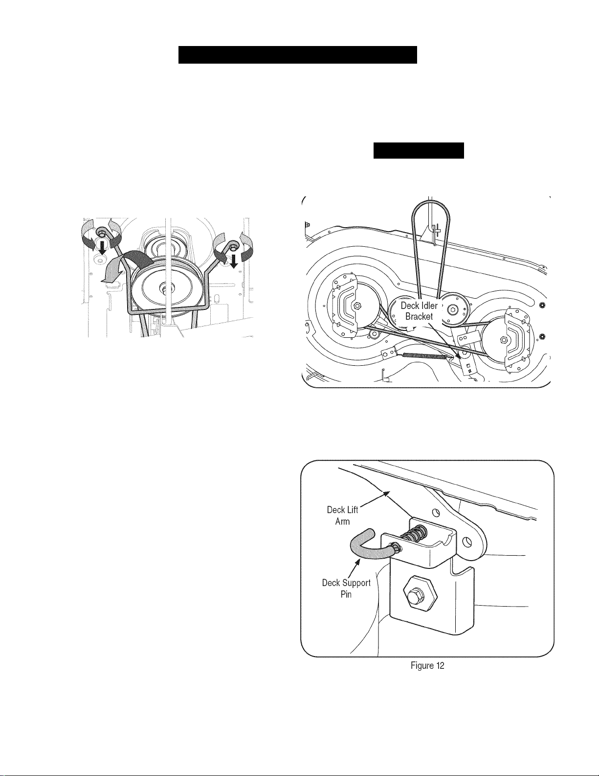
Looking at the cutting deck from the left side of the tractor, locate
the deck support pin on the rear left side of the deck.
Pull the deck support pin outward to release the deck from the
deck lift arm. See Figure 12.
20
Page 21
SERVICE AND MAINTENANCE
J
Repeat the above steps on the tractor's right side.
Move the deck lift lever into the top notch to raise the deck lift
arms up and out of the way.
Remove the cotter pin from the end of the stabilizer rod and slide
the stabilizer out of the hanger bracket on the deck. See
Figure 13.
Figure 13
10. Gently slide the cutting deck (from the right side) out from
underneath the tractor.
CHANGING THE DECK BELT
Awarning
The V-belts found on your tractor are specially designed to engage
and disengage safely. A substitute (non-OEM) V-belt can be danger
ous by not disengaging completely. For a proper working machine,
use factory approved belts as listed in the Parts List manual included
with this product..
All belts on your tractor are subject to wear and should be replaced it
any signs of wear are present. To change or replace the deck belt on
your tractor, proceed as follows:
1. Remove the deck as instructed on page 20.
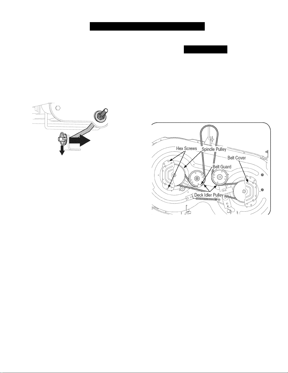
2. Remove the belt covers from the outer spindles by removing the
hex screws that fasten them to the deck. See Figure 14.
Figure 14
It may also be necessary to loosen the hex nut on the left idler
pulley to get the belt off the pulley and around the belt guard.
4.
Carefully remove the deck belt from around the two spindle
pulleys and the two deck idler pulleys. See Figure 14.
21
Page 22
SERVICE AND MAINTENANCE
I
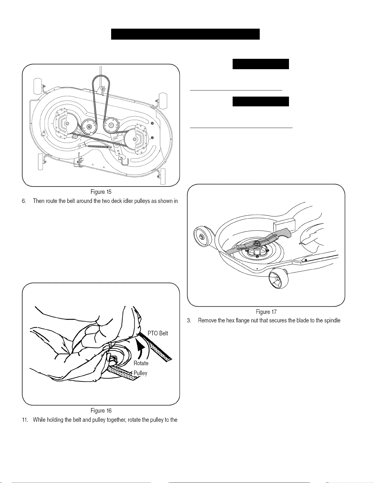
5. To place the new belt, begin by routing the belt around the two
outer spindle pulleys as shown in Figure 15.
Figure 15.
Retighten the belt keeper rod loosened earlier.
Remount the belt guards removed earlier.
Reinstall the deck as follows:
a. With the deck beneath the mower frame, attach the stabilizer
rod. See Figure 13.
b. Reconnect the deck lift arms. See Figure 12.
10.
Pull the right side of the belt and place the narrow V side of the
belt into the PTO pulley. See Figure 16.
CUTTING BLADES
Awarning
Shut the engine off and remove ignition key before removing the
cutting blade(s) for sharpening or replacement. Protect your hands by
using heavy gloves when grasping the blade.
_________________
AWARNING
Periodically inspect the blade and/or spindle for cracks or damage,
especially after you've struck a foreign object. Do not operate the
machine until damaged components are replaced.
To remove the blades, proceed as follows:
1.
Remove the deck from beneath the tractor, (refer to Cutting Deck
Removal earlier in this section) then gently flip the deck over to
expose its underside.
Place a block of wood between the center deck housing baffle
and the cutting blade to act as a stabilizer. See Figure 17.
______________
left (See Figure 16). Continue holding and rotating the pulley and
belt until the belt is fully rolled into the PTO pulley.
12. Replace the PTO pulley belt guard. See Figure 10.
assembly. See Figure 17.
22
Page 23
SERVICE AND MAINTENANC
J
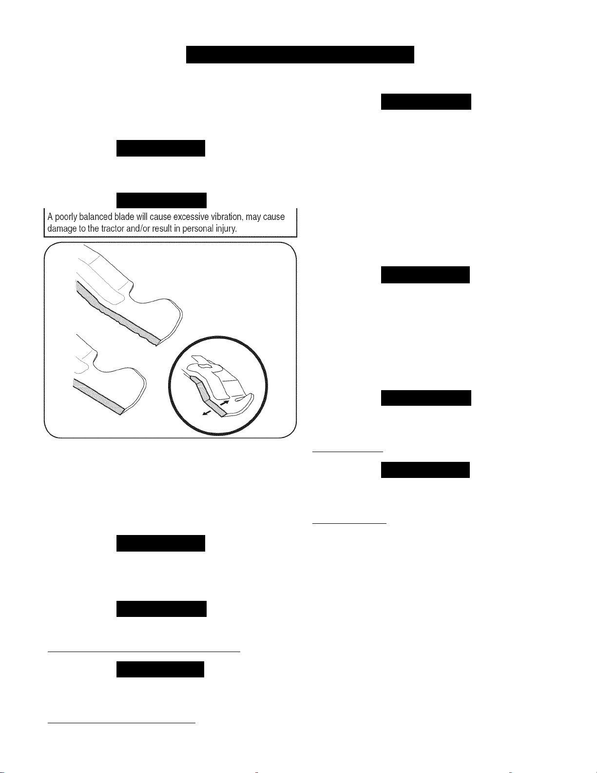
4. To properly sharpen the cutting blades, remove equal amounts
of metal from both ends of the blades along the cutting edges,
parallel to the trailing edge, at a 25“- 30“ angle. Always grind each
cutting blade edge equally to maintain proper blade balance. See
Figure 18.
A
CAUTION
If the cutting edge of the blade has previously been sharpened, or it
any metal separation is present, replace the blades with new ones.
AWARNING
Jump Starting
Never jump start a damaged or frozen battery. Be certain the vehicles
do not touch and ignitions are off. Do not allow cable clamps to touch.
1. Connect the positive (+) cable to positive (+) post of your tractor’s
2. Connect the other end of the cable to the positive
3. Connect the negative (-) cable to the negative (-) post of the
4. Make the final connection on the engine block of the tractor, away
If the jumper battery is installed on a vehicle (i.e. car, truck), do NOT
start the vehicle’s engine when jump starting your tractor.
5. Start the tractor (as instructed in the Operation section of this
6. Set the tractor’s parking brake before removing the jumper cables.
AWARNING
discharged battery.
(+)
post of the
jumper battery.
jumper battery.
from the battery. Attach to an unpainted part to assure a good
connection.
A
CAUTION
manual).
Remove cables in reverse order of connection.
Charging
Batteries give off an explosive gas while charging. Charge the battery
in a well ventilated area and keep away from an open flame or pilot
light as on a water heater, space heater, furnace, clothes dryer or
Figure 18
Test the blade’s balance using a blade balancer. Grind metal from
the heavy side until It balances evenly.
NOTE:
the side of the blade marked “Bottom” (or with a part number
stamped in it) facing the ground when the mower is in the operat
ing position.
Use a torque wrench to tighten the blade spindle hex flange nut to
between 70 ft-lbs and 90 ft-lbs.
When replacing the blade, be sure to install the blade with
A
CAUTION
other gas appliances.
When charging your tractor’s battery, use only a charger designed for
12V lead-acid batteries. Read your battery charger’s Owner’s Manual
prior to charging your tractor’s battery. Always follow its instructions
and heed its warnings.
If your tractor has not been put into use for an extended period of time,
charge the battery as follows:
1. Set your battery charger to deliver a max of 10 amperes.
2. If your battery charger is automatic, charge the battery until the
BATTERY
AWARNING
Battery posts, terminals, and related accessories contain lead and
lead compounds, chemicals known to the State of California to cause
cancer and reproductive harm. Wash hands after handling.
__________
AWARNING
__________________________________
A
CAUTION
_________________________________
charger indicates that charging is complete. If the charger is not
automatic, charge for no fewer than eight hours.
A
CAUTION
If removing the battery, disconnect the NEGATIVE (Black) wire from
its terminal first, followed by the POSITIVE (Red) wire. When reinstall
ing the battery, always connect the POSITIVE (Red) wire its terminal
first, followed by the NEGATIVE (Black) wire.
___________________
23
Page 24

SERVICE AND MAINTENANCE
FUSE
Awarning
Before servicing, repairing, or inspecting, always disengage PTO
(Blade Engage knob), set parking brake, stop engine and remove key
to prevent unintended starting.
A fuse is installed in your tractor's wiring harness to protect the trac
tor's electrical system from damage caused by excessive amperage.
If the electrical system does not function, or your tractor's engine will
not crank, first check to be certain that the fuse has not blown. It is
located under the hood, mounted behind the top of the dash panel on
the support bar.
____________________________
Although multi-viscosity oils (5W20,10W30, etc.) improve starting
in cold weather, they will result in increased oil consumption when
used above 32°F. Check your engine oil level more frequently to avoid
possible engine damage from running low on oil.
To check the engine oil, proceed as follows:
1. Ensure that the tractor is on a level surface.
2. Clean the oil fill area of any debris.
3. Remove the dipstick and wipe with a clean cloth.
4. Insert and tighten dipstick.
5. Remove the dipstick and check the oil level. It should be at the
Full mark on the dipstick. See Figure 19.
A CAUTION
Always use a replacement fuse with the same amperage capacity as
the blown fuse.
TIRES
AWARNING
Never exceed the maximum inflation pressure shown on the sidewall
of the tire.
Refer to the tire sidewall for exact tire manufacturer's recommended or
maximum psi. Do not overinflate.
Uneven tire pressure could cause the cutting deck to mow unevenly.
' ' ■iK’Cî'iStv,
l ^
CHANGING THE TRANSMISSION DRIVE
BELT
Several components must be removed and special tools used in order
to change the tractor's transmission drive belt. See a Sears or other
qualified service dealer to have the transmission drive belt replaced.
6. If low, add oil slowly into the engine oil fill. Do not overfill. After
ENGINE MAINTENANCE
Awarning
Before performing any maintenance or repairs, disengage PTO
(Blade Engage knob), set parking brake, stop engine and remove key
to prevent unintended starting.
Checking the Engine Oil
Only use high quality detergent oil rated with API service classification
SF, SG, SH, or SJ. Select the oil's SAE viscosity grade according to
the expected operating temperature. Follow the chart below.
/bolder -
____________________________
■32T ^Warmer\
5W20
Oil Viscosity Chart
SAE30
Do not overfill. Overfilling with oil may cause the engine to not start,
hard starting, or engine smoking. If over the FULL mark on the
dipstick, drain oil to reduce oil level to FULL mark on dipstick.
7. Replace and tighten dipstick.
_
Figure 19
adding oil, wait one minute and then recheck the oil level.
\
A
A CAUTION
24
Page 25
SERVICE AND MAINTENANCE
J
Changing the Engine Oil
AWARNING
If the engine has been recently run, the engine, muffler and sur
rounding metal surfaces will be hot and can cause bums to the skin.
Exercise caution to avoid bums.
NOTE:
complete an oil change, proceed as follows:
1. With engine OFF but still warm, disconnect spark plug wire and
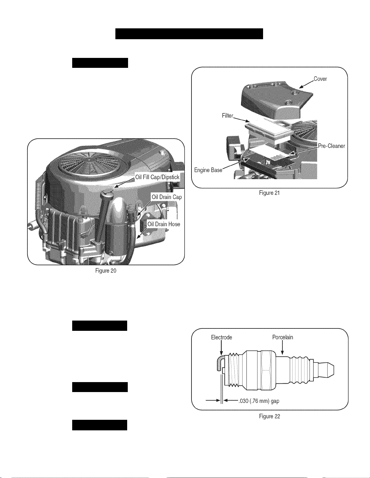
2. Remove the oil fill cap/dipstick from the oil fill tube. See Figure 20.
3. Disconnect the oil drain hose from the side of the engine.
4. Turn and remove the oil drain cap. Carefully lower the quick oil
5. After the oil has drained, install the oil drain cap. Attach the oil
The oil filter should be changed at every oil change interval. To
keep it away from spark plug.
drain into an approved container.
drain hose to the side of the engine.
A
CAUTION
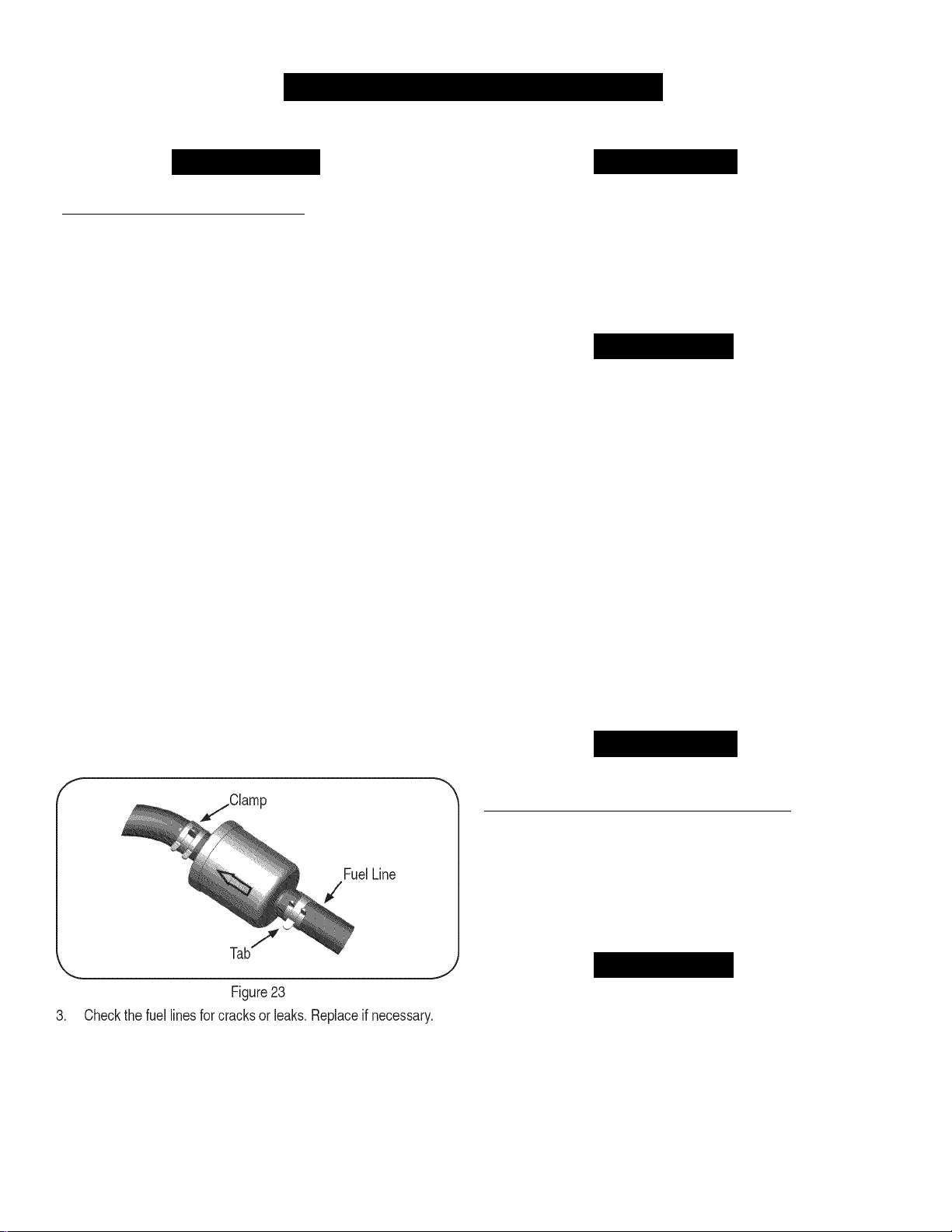
1. Remove the air filter cover.
2. To remove the air filter, lift the end of the filter. See Figure 21.
Spark Plug
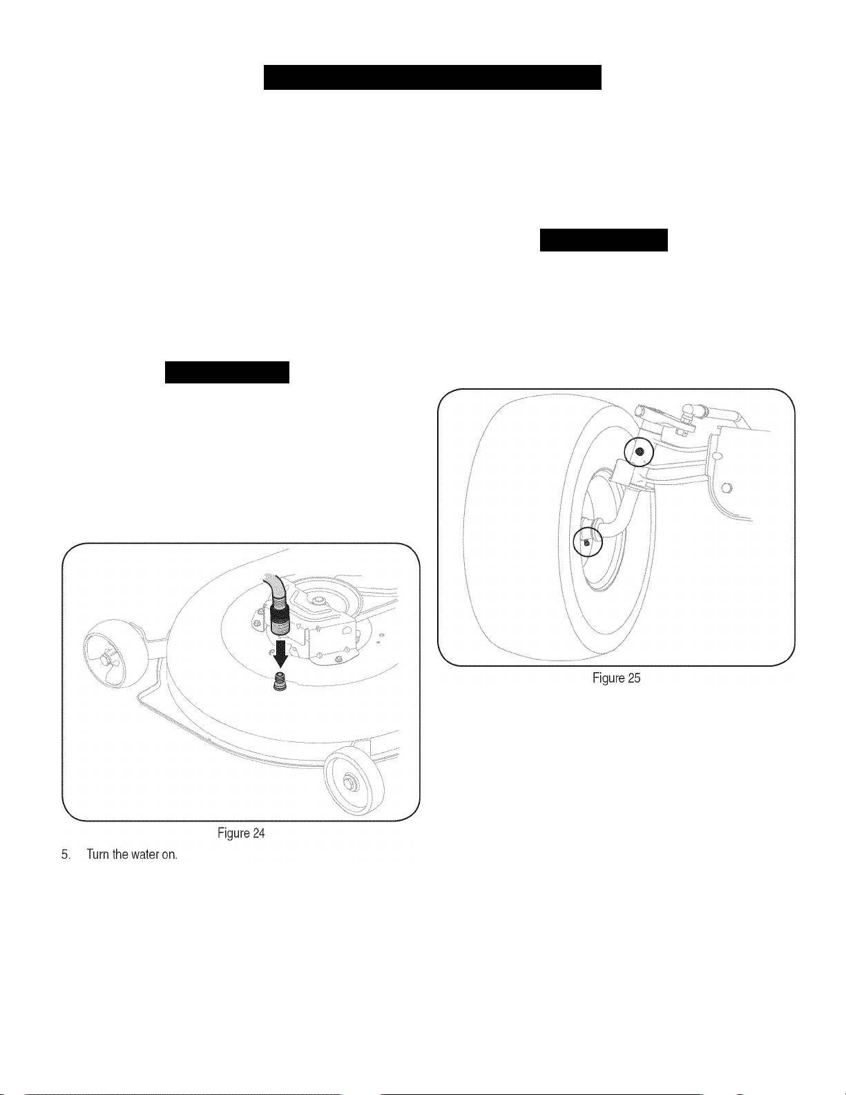
1. Clean area around the spark plug base. Do not sandblast spark
2. Remove and inspect the spark plug. Check gap to make sure it is
Remove the pre-cleaner from the filter.
To loosen debris, gently tap the filter on a hard surface. If the filter
is excessively dirty, replace with a new filter.
Wash the pre-cleaner in liquid detergent and water. Allow it to
thoroughly air dry.
Assemble the dry pre-cleaner to the filter.
Install the filter into the engine base and push down until the filter
snaps in place.
Install the cover.
plug. Spark plug should be cleaned by scraping or wire brushing
and washing with a commercial solvent
set at .030”. See Figure 22.
Do not
oil the pre-cleaner.
Used oil is a hazardous waste product. Dispose of used oil properly.
Do not discard with household waste. Check with your local authori
ties or Sears Service Center for safe disposal/recycling facilities.
6. Reconnect spark plug wire.
Air Cleaner
AWARNING
If filters, or covers are not installed correctly serious injury or death
could result from backfire. Do not attempt to start the engine with
them removed.
A
CAUTION
Do not use pressurized air or solvents to clean the air cleaner
cartridge.
Replace the spark plug (Champion® RC12YC) once a season.
Page 26
SERVICE AND MAINTENANCE
Fuel Filter IVluffler
AWARNING
Gasoline and its vapors are extremely flammable and explosive. Fire
or explosion can cause severe burns or death.
• Keep gasoline away from sparks, open flames, pilot lights, heat,
and other ignition sources.
• Check fuel lines, tank, cap, and fittings frequently tor cracks
or leaks. Replace it necessary. See a Sears or other qualified
service dealer to replace fuel line.
• Before replacing the fuel filter, drain the fuel tank or close the fuel
shut-off valve.
• Replacement parts must be the same and installed in the same
position as the original parts.
• If fuel spills, wait until it evaporates before starting engine.
To Drain the Fuel:
1. Locate the fuel filter, which is routed on the left side of the engine
between the fuel tank and the carburetor, and may be attached to
the engine with a tie strap.
2. Cut the tie strap, if present, then pinch the in-line clamp on the
fuel filter with a pair of pliers.
3. Slide the clamp up the fuel line.
4. Remove the in-line fuel line and drain the fuel into an approved
container.
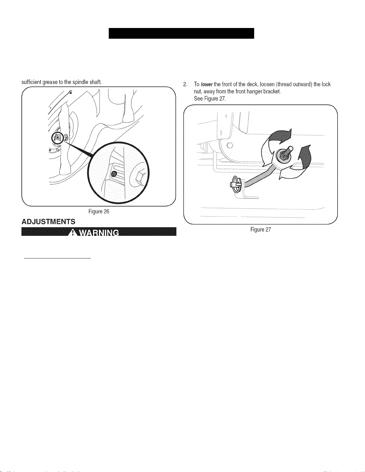
To Replace the Fuel Filter:
1. Before replacing the fuel filter, drain the fuel tank or close the fuel
shut-off valve. Otherwise, fuel can leak out and cause a fire or
explosion.
2. Use pliers to squeeze tabs on the clamps, then slide the clamps
away from the fuel filter. Twist and pull the fuel lines off of the fuel
filter. See Figure 23.
__________________
Temperature of muffler and nearby engine areas may exceed 150° F
(65°C). Avoid contact with these areas.
Inspect muffler periodically, and replace if necessary. Replacement
parts for the muffler must be the same and installed in the same
position as the original parts. See the Parts List manual included with
this tractor.
Clean Engine
Do not use water to clean engine parts. Water could contaminate fuel
system. Use a brush or dry cloth.
• Daily or before every use, clean grass, chaff or accumulated
• Keep area around and behind muffler free of any combustible
• Keeping engine clean allows air movement around engine.
• Engine parts should be kept clean to reduce the risk of overheat
Carburetor Adjustment
The carburetor on this engine is not adjustable.
Hydrostatic Transmission
The hydrostatic transmission is sealed at the factory and is mainte
nance-free. The fluid level cannot be checked and the fluid cannot be
changed.
Battery
Battery posts, terminals, and related accessories contain lead and
lead compounds, chemicals known to the State of California to cause
cancer and reproductive harm. Wash hands after handling.
The battery is sealed and is maintenance-free. Acid levels cannot be
checked and fluid can not be added.
• Always keep the battery cables and terminals clean and free of
• After cleaning the battery and terminals, apply a light coat of
AWARNING
A CAUTION
debris from engine. Keep linkage, spring, and controls clean.
debris.
ing and ignition of accumulated debris.
AWARNING
__________
corrosive build-up.
petroleum jelly or grease to both terminals.
Replace the fuel filter with an original equipment replacement
filter.
Secure the fuel lines with the clamps.
26
A CAUTION
If removing the battery for cleaning, disconnect the NEGATIVE
(Black) wire from its terminal first, followed by the POSITIVE (Red)
wire. When re-installing the battery, always connect the POSITIVE
(Red) wire to its terminal first, followed by the NEGATIVE (Black)
wire. Be certain that the wires are connected to the correct terminals;
reversing them could result in serious damage to your engine’s
alternating system.
Page 27
SERVICE AND MAINTENANCE
11.
CLEANING THE TRACTOR
Any fuel or oil spilled on the machine should be wiped off promptly. Do
NOT allow debris to accumulate around the cooling fins of the engine,
the transmission's cooling fan or on any other part of the machine,
especially the belts and pulleys.
Turn
port on your deck’s surface.
After cleaning your deck, return to the operator's position and engage
the PTO. Keep the cutting deck running for a minimum of two minutes,
allowing the underside of the cutting deck to thoroughly dry.
the water off and detach the hose coupler from the water
Deck Wash System
Your tractor’s deck is equipped with a water port on its surface as part
of its deck wash system.
Use the deck wash to rinse grass clippings from the deck’s underside
and prevent the buildup of corrosive chemicals. Complete the following
steps AFTER EACH MOWING:
1. Drive the tractor to a level, clear spot on your lawn, near enough
for your garden hose to reach.
A CAUTION
Make certain the tractor’s discharge chute is directed AWAY from yout
house, garage, parked cars, etc.
Disengage the PTO (Blade Engage), set the parking brake and
stop the engine.
Thread the hose coupler (packaged with your tractor’s Operator’s
Manual) onto the end of your garden hose.
Attach the hose coupler to the water port on your decks surface.
See Figure 24.
LUBRICATION
Before lubricating, repairing, or inspecting, always disengage PTO,
set parking brake, stop engine and remove key to prevent unintended
starting.
Front Wheels
Each of the front wheel axles and rims is equipped with a grease
fitting. See Figure 25. Lubricate with a No. 2 multi-purpose grease
applied with a grease gun after every 25 hours of tractor operation.
Awarning
Pivot Points & Linkage
Lubricate all the pivot points on the drive system, parking brake and lift
linkage at least once a season with light oil.
Deck Wheels
Each of the tractor deck’s front gauge wheels is equipped with a
grease fitting. Lubricate with a No. 2 multi-purpose grease applied with
a grease gun after every 25 hours of tractor operation.
6. While sitting in the operator’s position on the tractor, start the
engine and place the throttle lever in the FAST (rabbit) position.
7. Move the tractor's PTO (Blade Engage) into the ON position.
8. Remain in the operator's position with the cutting deck engaged
for a minimum of two minutes, allowing the underside of the
cutting deck to thoroughly rinse.
9. Move the tractor’s PTO (Blade Engage) into the OFF position.
10. Turn the ignition key to the STOP position to turn the tractor’s
engine off.
27
Page 28
SERVICE AND MAINTENANCE
Deck Spindle
Grease fittings can be found on each deck spindle. See Figure 26.
Lubricate with 251H EP grease or an equivalent No. 2 multi-purpose
lithium grease. Using a grease gun, apply two strokes (minimum) or
Determine the approximate distance necessary for proper adjustment
and proceed, it necessary.
1. To
raise
the front of the deck, tighten (thread inward) the lock nut
against the front hanger bracket. See Figure 27.
Shut the engine off, remove the ignition key and engage the parking
brake before making adjustments. Protect your hands by using heavy
gloves when handling the blades.
NOTE:
leveling adjustments. Refer to Tires on page 24 for information regard
ing tire pressure.
Check the tractor's tire pressure before performing any deck
__________________________
Leveling the Deck (Front To Rear)
The front of the cutting deck is supported by a stabilizer bar that can
be adjusted to level the deck from front to rear. The front of the deck
should be between 1/4-inch and 3/8-inch lower than the rear of the
deck. Adjust it necessary as follows:
1. Park the tractor parked on a firm, level surface and place the deck
lift lever in the middle position.
2. Rotate the blade nearest the discharge chute cover so that it is
parallel with the tractor.
3. Measure the distance from the front of the blade tip to the ground
and the rear of the blade tip to the ground. The first measurement
taken should be between 1/4” and 3/8” less than the second
measurement.
Leveling the Deck (Side to Side)
If the cutting deck appears to be mowing unevenly, a side to side
adjustment can be performed. Adjust it necessary as follows:
1. With the tractor parked on a firm, level surface, place the deck lift
2. Measure the distance from the outside of the left blade tip to the
lever in the middle position and rotate both blades so that they are
perpendicular with the tractor.
ground and the distance from the outside of the right blade tip to
the ground. Both measurements taken should be equal. If they're
not, proceed to the next step.
28
Page 29
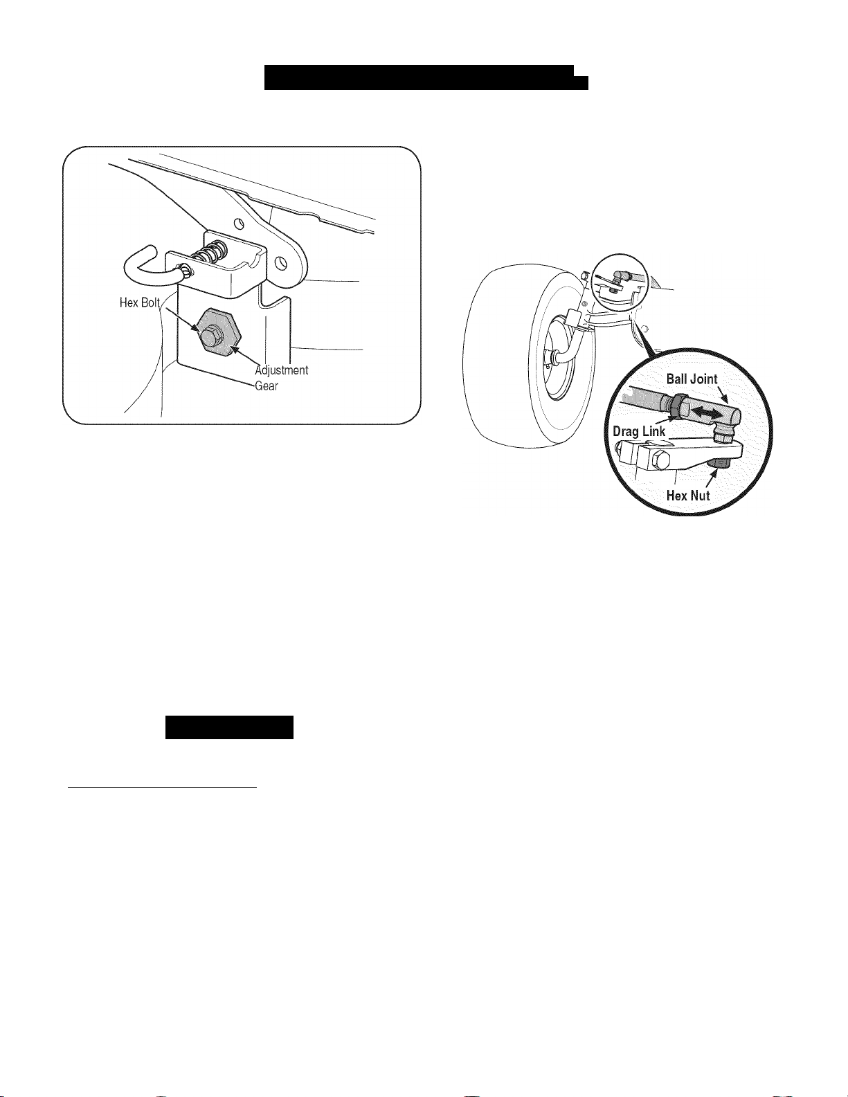
SERVICE AND MAINTENANC
I
J
3. Loosen, but do NOT remove, the hex bolt on the left deck hanger
bracket. See Figure 28.
Figure 28
4. Using a wrench, raise or lower the left side of the deck by turning
the adjustment gear. See Figure 28.
The deck Is properly leveled when both blade tip measurements
taken earlier are equal. RetIghten the hex bolt on the left deck hanger
bracket when proper adjustment Is achieved.
Parking Brake Adjustment
If the tractor does not come to a complete stop when the brake pedal
Is completely depressed, or If the tractor's rear wheels can roll with
the parking brake applied (and the transmission relief valve open), the
brake is in need of adjustment. See a Sears or other qualified service
dealer to have the brake properly adjusted.
Steering Adjustment
If the tractor turns tighter in one direction than the other, or it the ball
joints are being replaced due to damage or wear, the steering drag
links may need to be adjusted.
Adjust the drag links so that equal lengths of each are threaded into
the ball joint on the left side and the ball joint on the right side:
1. Remove the hex nut below the ball joint. See Figure 29.
2. Thread the ball joint inward to shorten the drag link. Thread the
3. Replace the hex nut after proper adjustment is achieved.
NOTE:
the front tires to “toe-in” too tar. Proper toe-in is between 1/16” and
5/16”.
Adjusting the Seat
Refer to the Assembly section of this manual for seat adjustment
instructions.
4. Front tire toe-in can be measured as follows:
Awarning
Before operating the tractor, make sure the seat is engaged in the
seat-stop. Engage the parking brake. Stand behind the machine and
pull back on seat until it clicks into place.
_____________________
Figure 29
ball joint outward to lengthen the drag link.
Threading the ball joints too far onto the drag links will cause
a. Place the steering wheel in position tor straight ahead travel.
b. In front of the axle, measure the distance horizontally from
the inside of the left rim to the inside of the right rim. Note the
distance.
c. Behind the axle, measure the distance horizontally from the
inside of the left rim to the inside of the right rim. Note the
distance.
d. The measurement taken in front of the axle should be
between 1/16” and 5/16” less than the measurement taken
behind the axle.
29
Page 30

OFF-SEASON STORAGE
Awarning
Never store lawn tractor with fuel in tank indoors or in poorly
ventilated areas where fuel fumes may reach an open flame, spark,
or pilot light as on a furnace, water heater, clothes dryer, or gas
appliance.
J
PREPARING THE ENGINE
IMPORTANT:
rates and will cause serious starting problems.
To prevent gum deposits from forming inside the engine’s carburetor
and causing possible malfunction of the engine, the fuel system must
be either completely emptied, or the gasoline must be treated with a
stabilizer to prevent deterioration.
If using a fuel stabilizer:
a. Read the product manufacturer’s instructions and recom
b. Add to clean, fresh gasoline the correct amount of stabilizer
c. Fill the fuel tank with treated fuel and run the engine for 2-3
If emptying the fuel system:
a. Do not drain fuel when the engine is hot. Allow the engine
b. Drain any large volume of fuel from the tank by disconnect
Fuel left in the fuel tank during warm weather deterio
mendations.
for the capacity of the fuel system.
minutes to get stabilized fuel into the carburetor.
adequate time to cool. Drain fuel into an approved container
outdoors, away from open flame.
ing the fuel line from the in-line fuel filter near the engine.
See To Drain the Fuel on page 26.
PREPARING THE LAWN TRACTOR
Awarning
Gasoline is extremely flammable and can be explosive under certain
conditions. Drain gasoline before storing the equipment for extended
periods. Drain fuel only into an approved container outdoors, away
from an open flame. Allow engine to cool. Extinguish cigarettes,
cigars, pipes, and other sources of ignition prior to draining fuel.
Store gasoline in an approved container in safe location.
• Clean and lubricate tractor thoroughly as described in the
lubrication instructions.
• Do not use a pressure washer or garden hose to clean your
unit.
• Store mower in a dry, clean area. Do not store next to
corrosive materials, such as fertilizer.
Reconnect the fuel line and run the engine until it starts to
falter, then use the choke to keep the engine running until all
fuel in the carburetor has been exhausted.
Disconnect the fuel line and drain any remaining gasoline
from the system.
Awarning
Gasoline is a toxic substance. Dispose of gasoline properly. Contact
your local authorities for approved disposal methods.
Remove the spark plug and pour one (1) ounce of engine oil through
the spark plug hole into the cylinder. Crank the engine several times to
distribute the oil. Replace the spark plug.
30
Page 31

I
1
Before performing any type of maintenance/service, disengage all
controls and stop the engine. Wait until all moving parts have come to
a complete stop. Disconnect spark plug wire and ground It against the
engine to prevent unintended starting. Always wear safety glasses during
operation or while performing any adjustments or repairs.
This section addresses minor service issues. To locate the nearest Sears Service Center or to schedule service, simply contact Sears
at 1-800-4-MY-HOME®.
TROUBLESHOOTIN
J
Awarning
Problem
Engine fails to start 1. PTO/Blade Engage knob engaged.
2. Parking brake not engaged. 2. Engage parking brake.
3. Spark plug wire disconnected. 3. Connect wire to spark plug.
4. Throttle/Choke control lever not in correct
starting position.
5. Fuel tank empty, or stale fuel. 5. Fill tank with clean, fresh (less than 30 days old) gas.
6. Blocked fuel line. 6. Replace fuel line. See a Sears or other qualified
7. Faulty spark plug.
8. Engine flooded. 8. Crank engine with throttle in FAST position.
Engine runs erratically 1. Tractor running with Choke activated. 1. Move the Throttle/Choke control lever out of the
2. Spark plug wires loose. 2. Connect and tighten spark plug wires.
3. Blocked fuel line or stale fuel. 3. Replace fuel line. See a Sears or other qualified
4. Vent in gas cap plugged. 4. Clear vent or replace cap it damaged.
5. Water or dirt in fuel system. 5. Drain fuel tank. Refill with clean, fresh gasoline. See
6. Dirty air cleaner. 6. Replace air cleaner paper element or clean foam
Engine overheats 1. Engine oil level low 1. Fill engine with proper amount and type of oil.
2. Air flow restricted 2. Clean grass clippings and debris from around the
Engine hesitates at high RPMs 1. Spark plug gap set too close 1. Remove spark plug and adjust gap.
Engine idles poorly 1. Fouled spark plug 1. Replace spark plug and adjust gap.
2. Dirty air cleaner 2. Replace air cleaner element and/or clean pre
Excessive vibration 1. Cutting blades loose or unbalanced 1. Tighten blade and spindle. Balance blade.
2. Damaged, dull, or bent cutting blade 2. Replace blade.
Cause Remedy
1. Place knob in disengaged (OFF) position.
4. Place Throttle/Choke lever to FAST position.
service dealer. Replace fuel filter. See the Service
and Maintenance section.
7. Clean, adjust gap or replace plug.
choke position.
service dealer. Fill tank with clean, fresh gasoline
and replace fuel filter. See the Service and Mainte
nance section.
the Service and Maintenance section.
precleaner.
engine's cooling fins and blower housing.
cleaner.
31
Page 32

TROUBLESHOOTING
I
Mower will not mulch grass
Uneven cut
NEED MORE lELP?
Find this and all your other product manuals online.
Get answers from our team of home experts.
Get a personalized maintenance plan for your home.
Find information and tools to help with home projects.
II : . ,
1.
2.
3.
4.
1.
2.
3.
d
..............
Engine speed too low.
Wet grass.
Excessively high grass.
Dull blade.
Deck not leveled properly.
Dull blade.
Uneven tire pressure.
^3 /
brought to you by Sears
1.
Place Throttle/Choke control in FAST (rabbit)
position.
2.
Do not
mulch
3.
Mow once at a high cutting height, then mow again
at desired height or make a narrower cutting swath.
4.
Sharpen or replace blade.
1.
Perform side-to-side deck adjustment.
2.
Sharpen or replace blade.
3.
Check tire pressure in all four tires.
:aiia§einfi®iiie.coiE - f®r free!
when grass is wet.
32
Page 33

REPAIR PROTECTION AGREEMENT
Congratulations on making a smart purchase. Your new Craftsman®
product is designed and manufactured for years of dependable opera
tion. But like all products, it may require repair from time to time. That's
when having a Repair Protection Agreement can save you money and
aggravation.
Here’s what the Repair Protection Agreement* includes:
• Expert service
• Unlimited service and no charge
covered repairs
• Product replacement
fixed
• Discount of 10%
parts not covered by the agreement; also, 10% off regular price of
preventive maintenance check
• Fast help by phone
from a Sears representative. Think of us as a “talking owner’s
manual.”
by our 10,000 professional repair specialists
for parts and labor on all
up to $1500 it your covered product can’t be
from regular price of service and related installed
- we call it Rapid Resolution - phone support
Once you purchase the Agreement, a simple phone call is all that it
takes for you to schedule service. You can call anytime day or night, or
schedule a service appointment online.
The Repair Protection Agreement is a risk-free purchase. If you cancel
for any reason during the product warranty period, we will provide a full
refund. Or, a prorated refund anytime after the product warranty period
expires. Purchase your Repair Protection Agreement today!
Some limitations and exclusions apply. For prices and additional
information in the U.S.A. call 1-800-827-6655.
‘Coverage in Canada varies on some items. For full details call
Sears Canada at 1-800-361-6665.
Sears Installation Service
For Sears professional installation of home appliances, garage door
openers, water heaters, and other major home items, in the U.S.A. or
Canada call
1-800-4-MY-HOME®.
33
Page 34

Steering and Axle — Model No. 247.28672
PARTS LIS
J
34
34
Page 35

Steering and Axle — Model No. 247.28672
I
PARTS LIS
J
Ref.
No.
1 710-04095 Hex Head Screw, 3/8-16:1.00
2 710-0514 Hex Head Screw, 3/8-16:1.00
3 710-0643 Hex Head Screw, 5/16-18:1.00
4 711-04998 LH Drag Link
5 711-04999 RH Drag Link
6 912-0240 Jam Nut, 7/16-20
7 712-04065 Flangelock Nut, 3/8-16
8 712-0459 Flangelock Nut, 7/16-20
9 712-3004A Flangelock Nut, 5/16-18
10 717-1550F Steering Gear
11 717-1554 Steering Pinion Gear
12 923-0448A Ball Joint, 7/16-20
13 936-3004 Flat Washer, .406 X .875 X .105
14 736-3084 FlatWasher, .51X1.12X.06:HT
15 634-04405-4042 Rim Assembly
16 738-04263 Steering Shaft, .625 OD X 24.25 LG
17 738-04363 Shoulder Spacer, .385X 1.25 X .3025
18 741-04237B Hex Flange Bearing 5/8 PM
19 783-06043-0637 Steering Support Bracket
20 638-04021-0637 RH Axle Assembly
Part No. Description
Ref.
No.
21 638-04027-0637 LH Axle Assembly
22 710-0395 Hex Head Screw, 5/16-18:2.25
23 710-0859 Hex Head Screw, 3/8-16:2.50
24 710-3180 Hex Head Screw, 5/16-18:1.75
25 912-0214 Hexiock Nut, 3/8-24
26 712-04063 Flangelock Nut, 5/16-18
27 714-0162 Cotter Pin, 5/32:1.25
28 719-04413A Pivot Bar Axle
29 934-0255 Tubeless Air Valve
30 748-04065-0637 Steering Block
31 748-04068 Spacer, .71 ID X .125 OD X .56LG
32 750-05280 Spacer, .385 X 1.00 X 1.5075
33 731-05674 Bumper Cap
34 736-04228A Flat Washer, .781 ID x 1.590OD
35 631-04415 Steering Wheel
36 731-06825 Steering Wheel Cap
37 634-04406-0961 Wheel Assembly
38 734-1731-0901 Tire
39 741-0990B Flange Bearing, .760ID
40 741-0516B Flange Bearing, .760 x I.OOx 1.20LG
Part No. Description
Page 36

Hood and Dash — Model No. 247.28672
PARTS LIST
36
Page 37

Hood and Dash — Model No. 247.28672
I
PARTS LIS
J
Ref.
No.
1 631-04353P Dash Lever
2 710-04484 Taptite Screw, Lock Washer, 5/16-18:.750
3 710-0599 Taptite Screw, Lock Washer, 1/4-20:0.500
4 710-0895 Hi-Lo Screw, Lock Washer, 1/4-15:0.750
5 710-0896 Screw, Lock Washer, 1/4-14:0.625
6 710-1017 Screw, 1/4-14:0.625
7 710-1611B Taptite Screw, 5/16-18:0.750
8 710-3217 Machine Screw, #8-32:0.375
9 712-0142 Hex Nut, #8-32:GRA
10 714-04040 Bow-tie Cotter Pin
11 726-3046 Ratchet Clip:.250 DIA
12 731-07456 Dash
13 731-07550 Control Knob
14 732-04580 Extension Spring, .500 DIA X 2.733 LG
15 735-0271A Bumper
16 735-04076 Accessory Net
17 747-05280 Control Rod Latch
18 747-1196 Lever Rod
19 783-04285F-0637 RH Dash Support Plate
20 783-04323F-0637 LH Dash Support Plate
21 625-04124 Keys (Set of 2)
22 683-04618-0691 Hood Assembly
23 710-04187 Hi-lo Screw, Lock Washer, 1/4-15:0.50
24 710-05108 Screw, Lock Washer, 1/4 DIA:.750
25 931-07457 Grill
26 731-07458 RH Lens
27 731-07459 LH Lens
28 931-07461 Hood Scoop
Part No. Description
Ref.
No.
29 731-07467 Lower Grill
30 731-07469 LH Hood Scoop
31 731-07470 RH Hood Scoop
32 738-04091A Shoulder Screw, .43X.29:TT:5/16-18
33 710-0642 Taptite Screw, 1/4-20:0.750
34 747-05049 RH Tank Support Rod
35 747-05050 LH Tank Support Rod
36 783-06672-0637 Carbon Canister Mounting Bracket
37 751-10749 Fuel Hose
38 946-04556 Throttle/Choke Control
39 751-10750 Fuel Hose
40 731-07495 P-Style Plen
41 925-0963 Miniature Lamp, 12V
42 925-1649 Lamp Socket
43 725-04992 Switch Key Module
44 689-00157 Guard Assembly
45 712-04065 Flangelock Nut, 3/8-16
46 738-0143 Shoulder Bolt, .496 x .336:3/8-16
47 925-04036C Hour Meter
48 725-04258 PTO Switch
49 951-10589 Carbon Canister
50 951-10590 Canister Vent Filter
51 951-10610 Canister Adaptor Bracket
52 735-04081 Rubber Gromet
53 735-04170 Fuel Tank Gasket
54 751-10441 Rollover Valve
55 951-10947 Fuel Cap
—
Part No. Description
651-04269 Fuel Tank Assembly (refs. 52 - 55)
37
Page 38

Seat and Fender — Model No. 247.28672
PARTS LIS
J
38
34
P
Page 39

Seat and Fender — Model No. 247.28672
I
PARTS LIS
J
Ref.
No.
1 683-04223-0637 Lift Shaft Assembly
2 712-04063 Flangelock Nut, 5/16-18
3 712-04065 Flangelock Nut, 3/8-16
4 914-0104 Cotter Pin, .072 DIA. X 1.13LG
5 714-04040 Bow-Tie Cotter Pin
6 716-0106A E-Ring, .625 DIA. SHAFT
7 720-04150 Handle Grip
8 732-0874 Torsion Spring
9 736-0105 Spring Washer, .401 X .870 X .063
10 738-0138A Shoulder Screw, .437 X .470:5/16-18
11 738-04130 Shoulder Bolt, .625X.175:3/8-16
12 941-0225 Hex Flange Bearing
13 746-0968 Lift Cable, 16.16 LG
14 747-04962A Lift Handle
15 756-04331 Pulley Roller Cable
16 783-04494C-0637 RH Lift Arm
—
17 710-04482 Hex Head Flange, 3/8-16:.875
18 710-04484 Taptite Screw, Lock Washer, 5/16-18:.750
19 712-3004A Flangelock Nut, 5/16-18
20 725-0157 Cable Tie, 3/16 X .05X7.4
Part No. Description
783-04711C-0637 LH Lift Arm
Ref.
No.
21 732-04561 Compression Spring, 1.71 X 3.735 X .238
22 732-04563 Compression Spring, .68 X 1.065 X .055
23 938-0296 Shoulder Screw, .437 X .268:5/16-18
24 783-06049-0691 Seat Mounting Bracket
25 783-06050 Seat Adjustment Lever
26 783-06088-0691 Seat Pivot Bracket
27 783-06448 Switch Retainer Clip
28 710-04187 Hi-Lo Screw, Lock Washer, 1/4-15:0.50
29 710-0451 Carriage Bolt, 5/16-18:.750
30 710-0599 Taptite Screw, Lock Washer, 1/4-20:0.500
31 710-0895 Hi-Lo Screw, Lock Washer, 1/4-15:0.750
32 731-05837 LH Fender Cover
33 731-06754 RH Fender Cover
34 736-3078 Flat Washer, .344 X 1.00 X .063 HDN
35 783-06118-0691 Fender
36 726-3046 Ratchet Clip
37 735-04137 LH Foot Pad
—
38 757-04127 Seat
39 783-06181-0637 Lift Bracket
40 925-05013 Seat Switch
Part No. Description
735-04139 RH Foot Pad
39
Page 40

Drive and Rear Wheels — Model No. 247.28672
PARTS LIS
J
40
Page 41

Drive and Rear Wheels — Model No. 247.28672
I
PARTS LIS
J
Ref.
No.
1 918-0319 Hydro Transmission
2 710-0176 Hex Head Screw, 5/16-18:2.75
3 710-0227 Screw, indented Washer, #8-18:0.500
4 710-0351 Screw, #10-16:0.500
5 710-04484 Taptite Screw, indented Washer, 5/16-18:.750
6 710-0653 Taptite Screw, indented Washer, 1/4-20:0.375
7 710-1007 Taptite Sems Screw, :3/8-16:1.500
8 710-1325 Taptite Screw, indented Washer, 1/4-20:1.625
9 710-3011 Hex Head Screw, 3/8-16:2.25
10 912-0240 Jam Nut, 7/16-20
11 912-0346 Jamiock Nut, 1/2-20
12 712-04063 Flangelock Nut, 5/16-18
13 912-0431 Flangeiock Nut, 3/8-16
14 914-0111 Cotter Pin, 3/32:1.0
15 725-0157 Cable Tie. 3/16 X .05 X 7.4
16 725-04791A Jumper Harness
17 725-1644 Short Spring Switch
18 926-0154 Push Mount Cable Tie 7.5 LG
19 926-0320 Insulator Nut Plate
20 731-05299A Sleeve, .765 ID X 1.500 LG
21 731-06098 Hydro Fan
22 932-0209 Extension Spring, .48 OD X 2.03
23 732-04606 Extension Spring, .500 DIA X 12.6 LG
24 732-04624 Extension Spring, 1.00 DIA X 4.75
25 732-0716D Extension Spring, .59 OD X 4.00 LG
26 732-0729 Wire Ring
27 732-3118 Extension Spring, .375 OD X 1.44 LG
28 936-0264 Flat Washer, .330 X .630 X .0635
29 736-04263 Lock Washer
30 936-3008 Flat Washer, .344 X .750 X .120
31 736-3010 FlatWasher, .407X.812X.135
32 934-0255 Tubeless Air Valve
33 734-1730-0901 Tire
34 738-04420 Shoulder Spacer, 1.375 X .380 X .183
35 747-04139 Brake Rod
36 747-04957A Footpedal Bypass Transmission Rod
Part No. Description
Ref.
No.
37 747-04979 Hydro Control Rod
38 747-04991 Hydro Bypass Rod
39 750-04456 Spacer, 260 X.372 XI.420 LG
40 954-04207 V-Belt, 4L X 78.9 POLY
41 756-04224 Flat Idler Pulley, 2.75 OD
42 756-04308 Input Pulley, 4.13 DIA
43 756-04325 V Idler Pulley, X 3.06
44 783-06027A Center Idler Bracket
45 783-06133-0637 Hydro Mounting Bracket
46 783-06260-0637 Belt Disengage Support Bracket
47 783-1019 В Switch Actuator Bracket
48 647-04152A Brake Control Assembly
49 683-04488 Hydro Pedal Bracket Assembly
50 710-0604A Taptite Screw, Indented Washer, 5/16-18:0.625
51 711-05068 Clevis Pin, 5/16 X 3.985
52 712-04065 Flangelock Nut, 3/8-16
53 714-04040 Bow-Tie Cotter Pin
54 726-0214 Push Cap
55 732-04587 Extension Spring, .63 DIA X 4.95 LG
56 735-04118A Forward Pedal Pad
57 735-04135 Reverse Pedal Pad
58 735-04136 Brake Pedal Pad
59 736-0242 Bell Washer, .340 X .872 X .060
60 634-04369-4042 Rim Assembly
61 938-0380 Shoulder Bolt, .500 X .270:3/8-16
62 741-0495 Flange Bearing, .630 IDX .695 OD X .60
63 748-04203 Cruise Latch
64 783-05914 Pedal Support Bracket
65 783-05940 Pedal Support Bracket, 5/8
66 783-06059-0637 Drive Pedal Bracket
67 783-06103A-0637 Brake Pedal Bracket
68 634-0104-0961 Wheel Assembly
69 710-0627 Hex Head Screw, 5/16-24:.750
70 750-0204 Axle Hub
71 731-2290A Hub Cap
72 736-0430 Flat Washer, .350 x 1.59 x .062
Part No. Description
41
Page 42

Engine Accessories — Model No. 247.28672
PARTS LIS
I
42
Page 43

Engine Accessories — Model No. 247.28672
I
PARTS LIS
J
Ref.
No.
1 683-04549-0637 Muiffier Shield Assembly
2 710-0227 Screw, Indented Washer, #8-18:0.500
3 710-04683 Taptite Screw, Indented Washer, 3/8-16:1.000
4 710-0599 Taptite Screw, Indented Washer, 1/4-20:0.500
5 710-1314A Socket Head Screw, 5/16-18:.750
6 712-0271 Sems Nut, 1/4-20
7 783-06378A Heat Shield
8 721-0460 Exhaust Gasket
9 725-0157 Cable Tie, 3/16 X .05 X 7.4
10 726-0205 Hose Clamp, .490 DIA.
11 728-04000 Rivet, .188 DIA X .300 L
12 751-3141-14 Oil Drain Extension Hose
13 751-0564B Muffler Deflector
14 751-10349 Fuel Hose
15 751-10353 Long Muffler Deflector
16 951-10517A Oil Drain
17 751-10542A Muffler Deflector
Part No. Description
43
Page 44

PTO and Battery — Model No. 247.28672
PARTS LIS
J
Page 45

PTO and Battery — Model No. 247.28672
I
PARTS LIS
J
Ref.
No.
1 683-04469A-0691 Frame
2 710-04484 Taptite Screw, indented Washer, 5/16-18:.750
3 710-0599 Taptite Screw, indented Washer, 1/4-20:0.500
4 710-3005 Hex Head Screw, 3/8-16:1.25
5 712-04065 Flangeiock Nut, 3/8-16
6 738-04058 Shouider Spacer, .38 X 1.0 X .70
7 747-04121A Battery Holder Rod
8 783-0349-0637 Battery Tray
9 783-06089-0637 Seat Frame Bracket
10 710-04379A Hex Head Screw, 7/16-20:3.50
11 917-04163A Electric PTO Clutch
12 725-0157 Cable Tie, 3/16 x.05x7.4
13 936-0171 Lock Washer, 7/16
14 736-0277 Flat Washer, 1.031 x 1.620 x.095
15 712-0271 Sems Nut, 1/4-20
16 756-0978B Electric PTO Engine Pulley
17 710-04666 Hex Head Flange, 1/4-20:.75
18 747-05171 Belt Guard
19 725-05088 Battery
20 725-04439 Solenoid, 12 V
21 712-04064 Flangeiock Nut, 1/4-20
22 725-04363 Interlock Switch
23 738-04237A Shoulder Screw, #10-32:.500
Part No. Description
45
Page 46

Deck — Model No. 247.28672
''36
¿'"40
55, (c
^''53
¿'42
4
PARTS LIS
J
46
¿^2?===^
14
”T—j>
.12
'''34
Page 47

Deck — Model No. 247.28672
I
PARTS LIS
J
Ref.
No.
1 618-04950 Spindie Assembiy
2 683-0254B-4028 Deck Hanger Bracket Assembly
3 683-04598-0428 Deck Assembly
4 710-04484 Taptite Screw, Indented Washer, 5/16-18:.750
5 710-0514 Hex Head Screw, 3/8-16:1.00
6 710-0528 Hex Head Screw, 5/16-18:1.25
7 710-0599 Taptite Screw, Indented Washer, 1/4-20:0.500
8 710-3144 Hex Head Screw, 3/8-16:2.00
9 710-3178 Carriage Bolt, 3/8-16:0.75
10 712-0229 Push Nut, 3/8
11 712-04065 Flangelock Nut, 3/8-16
12 712-0417A Flange Nut, 5/8-18
13 712-04243 Lock Nut, 1/2-13
14 912-0641 Hex Nut, M16-1.5 DIN 936
15 753-04070 Lynch Pin, .1875
16 914-0470 Cotter Pin, 1/8 X 1.25
17 917-04074 Deck Gear
18 921-04041 Water Nozzle Adaptor
19 732-0459C Extension Spring, .94 DIA. X 6.74 LG
20 732-04652 Compression Spring, .535 CD X 1.751 LG
21 734-04155 Front Deck Wheel
22 734-0973 Rear Deck Wheel
23 936-0119 Lock Washer, 5/16
24 936-0179 Flat Washer, .531 X 1.25 X.100
25 736-0225 Lock Washer, 5/8
26 736-0258 Flat Washer, .385 X 1.0 X .135
27 736-0262 Flat Washer, .385 X .870 X .092
28 736-0317 BellWasher, .63X 1.25X.18
Part No. Description
Ref.
No.
29 936-0344 Flat Washer, .385 X 1.0 X .030
30 737-04003D Water Nozzle
31 938-0373 Shoulder Bolt, .496 X 1.525:3/8-16
32 738-04162A Shoulder Spacer, .8840 X .190
33 938-3056 Shoulder Bolt, .496X2.50:3/8-16
34 942-04308 2-in-1 Cutting Blade
35 747-04944B Deck Lift Rod
36 956-1227 Deck Pulley, 6.3 DIA
37 747-1116 Deck Release Handle Rod
38 954-04060B V-Belt
39 756-04129B Idler Pulley, 4.25"DIA
40 936-0351 Flat Washer, .760 IDX1.50 CD
41 783-04740-0637 Deck Engage Cable Bracket
42 738-1186A Spindle Shaft, 6.05 LG.
43 783-05946 Idler Bracket
44 783-06243-0637 Deck Engage Cable Bracket
45 783-06368-0637 4.25 Pulley Belt Guard Bracket
46 783-06424A-4028 Belt Cover
47 783-06632-4028 Deck Stop
48 783-06643-4028 Deck Idler Support Bracket
49 711-04847A Hinge Pin
50 732-04372 Torsion Spring
51 783-06074A Chute Bracket
52 631-04460 Chute Deflector
53 941-0919 Ball Bearing, .7871D X 1.85 ODX.551
54 750-04936 Spacer, .792 X 1.060 X 1.860 LG
55 750-0952 Spacer, .792 X 1.060 X 1.800 LG
Part No. Description
47
Page 48

PARTS LIST
Engine — Model No. 247.28672
1329 REPLACMENT ENGINE |1330 REPAIR MANUAL| 48 SHORT BLOCK 1058 OPERATOR’S MANUAL
227 ......................................
562 W
278
505
212
523
842
287
219]
615
220
1027
186A 512
524
46
45,
,m^
850
252
250
10
48
22
9\i
Page 49

Engine — Model No. 247.28672
I
PARTS LIS
J
1251
26^
7^
^ / .
27«
1460
741
29j
24 m
27
125
141 231
108
32
51
51A
50
617
54
929 .fj
51A .
51Ap
418 1 f
672
51A|
. .. . J
X 163
J1169/
C;':
415 i
1131
¡987
212//
1861
142
!1128 I 4
! 150 i
16315
95 s 130
654 ■ s
53
240
iX
118
¥j>
....
703 ' '0-
387
385 X*
187
634
633 217
H
117
947 i
276
45) — OOX
1051
135 ©S'
1124A
11261
1124 C/
J8]..j
i i
I i
133
104 =
W5\
137 /
1127
276 <
49
Page 50

Engine ■ Model No. 247.28672
PARTS LIST
1005
1070f
74f
332 I
75 I
635 #
333
851
209^
729A^
334
‘‘ '^wl
211
' ■>
309
216
I ^ 7 f
l'' ^ ' ri •-
227
278
505 ® ® iJ
729J
188^
265 lU
267 g
562
726
695
165®
' \
1054
697
t
526
501
t
510
513
10510
783 l|
ii' ii
I i ]
579
1090
Ill
'111 (Ji'ii
1119
8021 , f" cl
50
Page 51

Engine — Model No. 247.28672
PARTS LIST
J
34
3^
42
798
1023
1022
914 (f#
918
192
850
13
617^^
5A
33
a.
j
42
617/^
Vi
1100
798
635 ¿..i
337
850
51
Page 52

Engine — Model No. 247.28672
1040
PARTS LIS
J
1036 EMISSIONS LABEL
703
304
I
305A
431
163
p^ji
X"®'
\ ,
...
.....
...
^Mii
......
305
.
.
306A
S' r-
j-'}
447
4455
967
52
573
197^^
\
®;.
/
Page 53

Engine — Model No. 247.28672
I
PARTS LIS
J
163
1095 VALVE GASKET SET
1022
53
Page 54

Engine — Model No. 247.28672
PARTS LIST
Ref. No. Part No. Description
1 793564 Cylinder Assembly
2 499585 Kit-Bushing/Seal (Magneto Side)
3 + 391086s Seal-Oil (Magneto Side)
4 796307 Sump-Engine
5 796231 Head-Cylinder (Cylinder #1)
5A 796232 Head-Cylinder (Cylinder #2)
7+& 693997 Gasket-Cylinder Head
8 792185 Breather Assembly
9 + 690937 Gasket-Breather
10 697551 Screw (Breather Assembly)
11 792184 Tube-Breather
12 + 697227 Gasket-Crankcase
13 793988 Screw (Cylinder Head)
15 690946 Plug-Oil Drain
16 796540 Crankshaft
20 + 795387 Seal-Oil (PTO Side)
22 694966 Screw (Crankcase Cover/Sump)
23 691053 Flywheel
24 222698s Key-Flywheel
25 792023 Piston Assembly (Standard)
25 792072 Piston Assembly (.020” Oversize)
26 793561 Ring Set (Standard)
26 792073 Ring Set (.020” Oversize)
27 690975 Lock-Piston Pin
28 696581 Pin-Piston
29 796209 Rod-Connecting
32 690976 Screw (Connecting Rod)
33 697576 Valve-Exhaust
34 792200 Valve-Intake
35 694865 Spring-Valve (Intake)
36 694865 Spring-Valve (Exhaust)
42 499586 Keeper-Valve
45 690977 Tappet-Valve
46 792242 Gear-Cam
48 797093 Short Block
50 695241 Manifold-Intake
51 + 795123 Gasket-Intake
51A 690950 Gasket-Intake
51B 690949 Gasket-Intake
Ref. No. Part No. Description
53 690951 Stud (Carburetor)
54 699816 Screw (Intake Manifold)
73 494439 Screen-Rotating
74 698425 Screw (Rotating Screen)
75 691056 Washer (Flywheel)
95 690718 Screw (Throttle Valve)
98 699721 Kit-Idle Speed
104 % 694918 Pin-Float Hinge
105 698537 Valve-Float Needle
108 699723 Valve-Choke
117 842630 Jet-Main (Standard)
118 797477 Jet-Main (High Altitude)
121 792455 Kit-Carburetor Overhaul
125 796997 Carburetor
130 690993 Valve-Throttle
131 499805 Kit-Throttle Shaft
133 699724 Float-Carburetor
135 699729 Tube-Fuel Transfer
137 % 690994 Gasket-Float Bowl
141 796228 Kit-Choke Shaft
142 699726 Nozzle-Carburetor
146 690979 Key-Timing
150 690995 Gasket-Nozzle
163+% 691001+ Gasket-Air Cleaner
165 693148 Nut (Ring Gear)
186 795985 Connector-Hose
186A 796532 Connector-Hose (Oil Drain Hose)
187 791766 Line-Fuel (Cut to Required Length)
188 697551 Screw (Control Bracket)
192 690083 Adjuster-Rocker Arm
197 697820 Screw (Back Plate)
209 796658 Spring-Governor (Yellow/Brown)
211 796225 Spring-Governed Idle (Orange)
212 695238 Link-Throttle
216 796229 Link-Choke
217 695409 Spring-Choke Return
+ — Included in Engine Gasket Set, Key. No. 358
& — Included in Valve Gasket Set, Key No. 1095
% — Included in Carburetor Overhaul Kit, Key No. 121
54
Page 55

Engine — Model No. 247.28672
I
PARTS LIS
J
Ref. No. Part No. Description
219 793338 Gear-Governor
220 690412 Washer (Governor Gear)
221 841026 Cup-Governor
222 796226 Bracket-Control
227 796223 Lever-Governor Control
231 690718 Screw (Choke Valve)
240 695666 Filter-Fuel
250 690957 Retainer-Breather
252 794389 Collector-Oil
265 691024 Clamp-Casing
267 695134 Screw (Casing Clamp)
276 % 695410 Washer-Sealing
278 792651 Washer (Governor Control Lever)
287 697551 Screw (Dipstick Tube)
304 797407 Housing-Blower
305 691005 Screw (Blower Housing)
305A 790690
306 796541 Shield-Cylinder (Cylinder #2)
306A 796852 Shield-Cylinder (Cylinder #1)
307 697551 Screw (Cylinder Shield)
309 499521 Motor-Starter
310 691263 Screw (Starter Motor)
332 691059 Nut (Flywheel)
333 691060 Armature-Magneto
334 691061 Screw (Magneto Armature)
337 491055s Plug-Spark
358 694012 Gasket Set-Engine
385 797409 Screw (Fuel Pump)
387 808656 Pump-Fuel
404 690442 Washer (Governor Crank)
415 794903 Plug (Oil Pressure Switch Hole)
418 795912 Plate-Carburetor
431 792297 El bow-Intake
445 792105 Filter-Air Cleaner Cartridge
447 691003 Screw (Air Guide Cover)
467 790697 Knob-Air Cleaner
474 696458 Alternator
501 797375 Regulator
Screw (Blower Housing to Intake
Elbow)
Ref. No. Part No. Description
503 691532 Strap-Starter
505 691029 Nut (Governor Control Lever)
510 696541 Drive-Starter
512 796530 Hose-Oil Drain
513 692024 Clutch-Drive
523 691036 Dipstick
524 + 691032 Seal-Dipstick Tube
525 691037 Tube-Dipstick
526 697551 Screw (Regulator)
544
552 796638 Bushing-Governor Crank
552A 690553 Bushing-Governor Crank
562 690311 Screw (Governor Control Lever)
573 790444 Plate-Back
579 691029 Nut (Starter Cable)
601 691038 Clamp-Hose (Black)
615 698290 Retainer-Governor Shaft
616 691045 Crank-Governor
617 697891 Seal-0 Ring (Intake Manifold) (Red)
633 % 699813 Seal-Choke/Throttle Shaft
634 698779 Spring/Seal Assembly
635 66538s Boot-Spark Plug
654 690958 Nut (Carburetor)
668 + 691215 Spacer (Rotating Screen)
668A 691500 Spacer (Rotating Screen)
672 690234 Gasket-Carburetor Plate
691 + 790574 Seal-Governor Shaft
695 693149 Screw (Ring Gear)
697 690372 Screw (Drive Cap)
703 691010 Clip
718 690959 Pin-Locating
726 499612 Gear-Ring
729 797454 Clip-Wire
741 690980 Gear-Timing
742 690328 Retainer-E Ring (Governor Crank)
+ — Included in Engine Gasket Set, Key. No. 358
& — Included in Valve Gasket Set, Key No. 1095
% — Included in Carburetor Overhaul Kit, Key No. 121
Armature-Starter (Service with Starter
Motor 499521, Reference 309)
55
Page 56

Engine — Model No. 247.28672
PARTS LIST
Ref. No. Part No. Description
750 796208 Screw (Oil Pump Cover)
783 695708 Gear-Pinion
789 797424 Harness-Wiring
798 697890 Screw (Rocker Arm)
801 691283 Cap-Drive
802 691286 Cap-End
803
842 691031 Seal-0 Ring (Dipstick Tube)
847 499602 Dipstick/Tube Assembly
850 100106 Sealant-Liquid
851 493880s Terminal-Spark Plug
865 792286 Cover-Air Guide (Valley)
868 + 690968 Seal-Valve
883 + & 690970 Gasket-Exhaust
914 691127 Screw (Rocker Cover)
918 797408 Hose-Vacuum
929 695239 Screw (Choke Control Bracket)
943 796222 Seal-0 Ring (Oil Pump Cover)
947 841546 Solenoid-Fuel
965 796221 Cover-Oil Pump
967 792303 Filter-Pre Cleaner
968 795120 Cover-Air Cleaner
975 793592 Bowl-Float
987 691000 Seal-Throttle Shaft
1005 791236 Fan-Flywheel
1013 690954 Nipple-Oil Filter
1017 796214 Screen-Oil Pump
1022 690971 Gasket-Rocker Cover
1023 793146 Cover-Rocker (Cylinder #1)
1023A 499600 Cover-Rocker (Cylinder #2)
1024 796220 Pump-Oil
1026 690981 Rod-Push (Exhaust)
1026A 690982 Rod-Push (Intake)
1027 795890 Filter-Oil
1029 690972 Arm-Rocker
1036
1040 791237 Plate-Trim
Housing-Starter (Service with Starter
Motor 499521, Reference 309)
Label-Emissions (Available from a
Briggs & Stratton Authorized Dealer)
Ref. No. Part No. Description
1051 691265 Ring-Retaining (Starter Drive)
1054 280275 Tie-Cable
1058 277103 Operator's Manual
1059 698516 Kit-Screw/Washer (Alternator)
1070 791680 Screw (Flywheel Fan)
1090 691293 Retainer-Brush
1095 694013 Gasket Set-Valve
1100 791959 Pivot-Rocker Arm
1119 691183 Screw (Alternator)
1124 841653 Seal-0 Ring (Fuel Transfer Tube)
1124 A 690988 Seal-0 Ring (Fuel Transfer Tube)
1126 690991 Screw (Fuel Transfer Tube)
1127 695407 Screw (Fuel Bowl)
1128 690990 Screw (Carburetor Nozzle)
1169 690990 Screw (Carburetor Plate)
1330 273521 Repair Manual
1329 BS-44Q777-0137-G1 Replacement Engine
+ — Included in Engine Gasket Set, Key. No. 358
& — Included in Valve Gasket Set, Key No. 1095
% — Included in Carburetor Overhaul Kit, Key No. 121
56
Page 57

LABEL
777123379
J
777D14480
■ff
777I23357
777123132
777S30018
A DANGER
SERIOUS INJURY OR OEftYH
.'iny
13/
ASSEMBL|CIOTlDEFLiCTORTO™^^
KEEP HANDS AND FEET AWAY.
DO NOT OPERATE MOWER
UNLESS CHUTE DEFLECTOR
OR ENTIRE GRASS CATCHER IS
IN ITS PROPER PLACE.
THAT CAN BE THROWN
direction, wear SAEETT GLASSM
777S30503
I devices W fl-MI
777X43688
DO NOT
USE E8S OR FUEL
CONTAINING MORE
THAN 10% ETHANOL
из
P II II h I S S I II N Л
NOT STEP
777X44429
777D14477
777D14492
777I23355
M
CHOKE
ROTATING BLADES CAUSE
SERIOUS INJURY OR DEATH
DO NOT tm m m chudben ok others are
МШУ cm s m ш я with ш ъ щ off.
(DOWN
AND
BEHIND BEFORE AND WHILE
:EiS NOT RECOMMENDED.
ro AVOID SERIOUS INJURY OR DEATH
GO UP AND DOWN SLOPES, NOT ACROSS.
AVOID SUDDEN TURNS.
DO NOT OPERATE HIE UNIT WHERE IT COULD SLIP OR TIP.
IF MACHINE STOPS GOING UPHILL. STOP BLADE|S|
AND BACK DOWNHILL SLOWLY.
KEEP SAFETY DEVICES (GUARDS. SHIELDS. AND
SWITCHES. ETC.) IN PLACE AND WORKING.
REMOVE OBJECTS THAT COULD K THROWN BY THE BLADE(5|.
KNOW LOCATION AND FUNCTION OF ALL CONTROLS.
BE SURE BLADEIS) AND ENGINE ARE STOPPED BEFORE
PLACING HANDS OR FEET NEAR BLADE(S).
BEFORE LEAVING OPERATOR'S POSITION. DISENGAGE
BLADE(S). ENGAGE PARKING BRAKE. SHUT OFF AND
EMOVEXEY.
READ OPERATOR'S MANUAL
▲ WARNING^
57
777S33593
iEBLADES)?TO,/KIKf£R TAKE OFF)
. T UPM KEY TO REVERSE CAUTION MODE POSITION.
OF№cS3 REVERSE PUSH BlIITON. fftEO liVOiCArOA LiCf^r ON";
WHEN RED lBCSMT IS "ON" MACIIBNE CAN TIE OPERATED
5. RS;SUMBNU FORY
KEY TO “NORMAL MOWI
НСТГ.: IN BOTH Monrs, WHFM OPFRATOR LEAVrS SFAT,
. STOP UNLESS PARKING CRAKE IS SET .^ND
Page 58

Look For Relevant Emissions Dorabiiity Period and
Air Index Information On Your Engine Emissions Label
Engines that are certified to meet the California Air Resources Board (GARB) Tier 2 Emission Standards must
display information regarding the Emissions Durability Period and the Air Index. Sears Brands Management
Corporation makes this information available to the consumer on our emission labels.
The Emissions Durability Period describes the number of hours of actual running time for which the engine is
certified to be emissions compliant, assuming proper maintenance in accordance with the Operating & Mainte
nance Instructions. The following categories are used:
Moderate: Engine is certified to be emission compliant for 125 hours of actual engine running time.
Intermediate: Engine is certified to be emission compliant for 250 hours of actual engine running time.
Extended: Engine is certified to be emission compliant for 500 hours of actual engine running time.
For example, a typical walk-behind lawn mower is used 20 to 25 hours per year. Therefore, the Emissions
Durability Period of an engine with an intermediate rating would equate to 10 to 12 years.
The Air Index is a calculated number describing the relative level of emissions for a specific engine family. The
lower the Air Index, the cleaner the engine. This information is displayed in graphical form on the emissions label.
After July 1,2000, Look For Emissions Compliance Period
On Engine Emissions Compliance Label
After July 1, 2000 certain Sears Brands Management Corporation engines will be certified to meet the United
States Environmental Protection Agency (USEPA) Phase 2 emission standards. For Phase 2 certified engines, the
Emissions Compliance Period referred to on the Emissions Compliance label indicates the number of operating
hours for which the engine has been shown to meet Federal emission requirements.
For engines less than 225 cc displacement. Category C = 125 hours, В = 250 hours and A = 500 hours.
For engines of 225 cc or more. Category C = 250 hours, В = 500 hours and A = 1000 hours.
This is a generic representation of the emission label typically found on a certified engine.
58
GDOC-100182 Rev. В
Page 59

(This page applicable in the U.S.A. and Canada only.)
Sears Brands Management Corporation (Sears), the California Air Resources Board (CARB)
and the United States Environmental Protection Agency (U.S. EPA)
Emission Control System Warranty Statement (Owner’s Defect Warranty Rights and Obligations)
EMISSION
PIED ENGINES PURCHASED IN CALIFORNIA IN 1995 AND THEREAF- ELSEWHERE IN THE UNITED STATES (AND AFTER JANUARY 1,2001 IN
TER, WHICH ARE USED IN CALIFORNIA, AND TO CERTIFIED MODEL CANADA).
CONTROL WARRANTY COVERAGE IS APPLICABLE TO CERTI- YEAR 1997 AND LATER ENGINES WHICH ARE PURCHASED AND USED
California and United States Emission Control Defects Warranty Statement
The California Air Resources Board (CARB), U.S. EPA and Sears are pleased engine for the periods of time listed below, provided there has been no abuse,
to explain the Emission Control System Warranty on your model year 2000 and neglect or improper maintenance of your small off-road engine. Your emis-
later small off-road engine (SORE). In California, new small off-road engines
must be designed, built and equipped to meet the State’s stringent anti-smog
standards. Elsewhere in the United States, new non-road, spark-ignition
engines certified for model year 1997 and later must meet similar standards set
forth by the U.S. EPA. Sears must warrant the emission control system on your
sion control system includes parts such as the carburetor, air cleaner, ignition
system, muffler and catalytic converter. Also included may be connectors and
other emission related assemblies. Where a warrantable condition exists. Sears
will repair your small off-road engine at no cost to you including diagnosis, parts
and labor.
Sears Emission Control Defects Warranty Coverage
Small off-road engines are warranted relative to emission control parts defects part on your engine is defective, the part will be repaired or replaced by Sears,
for a period of one year, subject to provisions set forth below. If any covered
Owner’s Warranty Responsibilities
As the small off-road engine owner, you are responsible for the performance of
the required maintenance listed in your Operating and Maintenance Instruc
tions. Sears recommends that you retain all your receipts covering maintenance
on your small off-road engine, but Sears cannot deny warranty solely for the
lack of receipts or for your failure to ensure the performance of all scheduled
maintenance. As the small off-road engine owner, you should however be
aware that Sears may deny you warranty coverage if your small off-road engine
or a part has failed due to abuse, neglect, improper maintenance or unap
proved modifications. You are responsible for presenting your small off-road
engine to an Authorized Sears Service Dealer as soon as a problem exists. The
undisputed warranty repairs should be completed in a reasonable amount of
time, not to exceed 30 days. If you have any questions regarding your warranty
rights and responsibilities, you should contact a Sears Service Representative
at 1 -800-469-4663. The emission warranty is a defects warranty. Defects are
judged on normal engine performance. The warranty is not related to an in-use
emission test.
Sears Emission Control Defects Warranty Provisions
The following are specific provisions relative to your Emission Control Defects Warranty Coverage. It is in addition to the Sears engine warranty for non-regulated
engines found in the Operating and Maintenance Instructions.
1. Warranted Parts
Coverage under this warranty extends only to the parts listed below (the
emission control systems parts) to the extent these parts were present on
the engine purchased.
a. Fuel Metering System
• Cold start enrichment system
• Carburetor and internal parts
• Fuel Pump
b. Air Induction System
• Air cleaner
• Intake manifold
c. Ignition System
• Spark plug(s)
• Magneto ignition system
d. Catalyst System
• Catalytic converter
• Exhaust manifold
• Air injection system or pulse valve
e. Miscellaneous Items Used in Above Systems
• Vacuum, temperature, position, time sensitive valves
and switches
• Connectors and assemblies
2. Length of Coverage
Sears warrants to the initial owner and each subsequent purchaser that
the Warranted Parts shall be free from defects in materials and workman
ship which caused the failure of the Warranted Parts for a period of one
year from the date the engine is delivered to a retail purchaser.
In the USA and Canada, a 24 hour hot line,
1-800-469-4663,
has a menu of pre-recorded messages offering you engine maintenance information.
No Charge
Repair or replacement of any Warranted Part will be performed at no
charge to the owner, including diagnostic labor which leads to the
determination that a Warranted Part is defective, if the diagnostic work is
performed at an Authorized Sears Service Dealer. For emissions warranty
service contact your nearest Authorized Sears Service Dealer as listed in
the “Yellow Pages” under “Engines, Gasoline,” “Gasoline Engines,” “Lawn
Mowers,” or similar category.
Claims and Coverage Exclusions
Warranty claims shall be filed in accordance with the provisions of the
Sears Engine Warranty Policy. Warranty coverage shall be excluded for
failures of Warranted Parts which are not original Sears parts or because
of abuse, neglect or improper maintenance as set forth in the Sears
Engine Warranty Policy. Sears is not liable to cover failures of Warranted
Parts caused by the use of add-on, non-original, or modified parts.
Maintenance
Any Warranted Part which is not scheduled for replacement as required
maintenance or which is scheduled only for regular inspection to the effect
of “repair or replace as necessary” shall be warranted as to defects for the
warranty period. Any Warranted Part which is scheduled for replacement
as required maintenance shall be warranted as to defects only for the
period of time up to the first scheduled replacement for that part. Any
replacement part that is equivalent in performance and durability may
be used in the performance of any maintenance or repairs. The owner is
responsible for the performance of all required maintenance, as defined in
the Sears Operating and Maintenance Instructions.
Consequential Coverage
Coverage hereunder shall extend to the failure of any engine components
caused by the failure of any Warranted Part still under warranty.
GDOC-100188 Rev.B
59
Page 60

FEDERAL and/or CALIFORNIA EMISSION CONTROL WARRANTY STATEMENT
YOUR WARRANTY RIGHTS AND OBLIGATIONS
MTD Consumer Group Inc, the United States Environmental Protection Agency (EPA), and, for those products certified for sale in the state of California, the
California Air Resources Board (CARB) are pleased to explain the emission (evaporative and/or exhaust) control system (ECS) warranty on your outdoor 2006
and later small off-road spark-ignited engine and equipment (outdoor equipment engine) In California, new outdoor equipment engines must be designed, built and
equipped to meet the State’s stringent anti-smog standards (in other states, 1997 and later model year equipment must be designed, built, and equipped to meet
the U.S. EPA small off-road, spark ignition engine regulations. MTD Consumer Group Inc must warrant the ECS on your outdoor equipment engine for the period of
time listed below provided there has been no abuse, neglect or improper maintenance of outdoor equipment engine.
Your ECS may include parts such as the carburetor, fuel-injection system, the ignition system, catalytic converter, fuel tanks, fuel lines, fuel caps, valves, canisters,
filters, vapor hoses, clamps, connectors, and other associated emission-related components.
Where a warrantable condition exists, MTD Consumer Group Inc will repair your outdoor equipment engine at no cost to you including diagnosis, parts and labor.
MANUFACTURER’S WARRANTY COVERAGE:
This emission control system is warranted for two years. If any emission-related part on your outdoor equipment engine is defective, the part will be repaired or
replaced by MTD CONSUMER GROUP INC.
OWNER’S WARRANTY RESPONSIBILITIES:
As the outdoor equipment engine owner, you are responsible for performance of the required maintenance listed in your owner’s manual. MTD Consumer Group
Inc recommends that you retain all receipts covering maintenance on your outdoor equipment engine, but MTD Consumer Group Inc cannot deny warranty solely
for the lack of receipts.
As the outdoor equipment engine owner, you should however be aware that MTD Consumer Group Inc may deny you warranty coverage if your outdoor equipment
engine or a part has failed due to abuse, neglect, or improper maintenance or unapproved modifications.
You are responsible for presenting your outdoor equipment engine to MTD Consumer Group Inc’s distribution center or service center as soon as the problem
exists. The warranty repairs should be completed in a reasonable amount of time, not to exceed 30 days. If you have a question regarding your warranty coverage,
you should contact the MTD Consumer Group Inc Service Department at 1-800-800-7310 or via email at
GENERAL EMISSIONS WARRANTY COVERAGE:
http://support.mtdproducts.com
MTD Consumer Group Inc warrants to the ultimate purchaser and each subsequent purchaser that the outdoor equipment engine is: Designed, built and equipped
so as to conform with all applicable regulations; and free from defects in materials and workmanship that cause the failure of a warranted part to be identical in all
material respects to that part as described in MTD Consumer Group Inc’s application for certification.
The warranty period begins on the date the outdoor equipment engine is delivered to an ultimate purchaser or first placed into service. The warranty period is two
years.
Subject to certain conditions and exclusions as stated below, the warranty on emission-related parts is as follows:
1. Any warranted part that is not scheduled for replacement as required maintenance in the written instructions supplied, is warranted for the warranty period
stated above. If the part fails during the period of warranty coverage, the part will be repaired or replaced by MTD Consumer Group Inc according to subsection
(4) below. Any such part repaired or replaced under warranty will be warranted for the remainder of the period.
2. Any warranted part that is scheduled only for regular inspection in the written instructions supplied is warranted for the warranty period stated above. Any such
part repaired or replaced under warranty will be warranted for the remaining warranty period.
3. Any warranted part that is scheduled for replacement as required maintenance in the written instructions supplied is warranted for the period of time before the
first scheduled replacement date for that part. If the part fails before the first scheduled replacement, the part will be repaired or replaced by MTD Consumer
Group Inc according to subsection (4) below. Any such part repaired or replaced under warranty will be warranted for the remainder of the period prior to the
first scheduled replacement point for the part.
4. Repair or replacement of any warranted part under the warranty provisions herein must be performed at a warranty station at no charge to the owner.
5. Notwithstanding the provisions herein, warranty services or repairs will be provided at all of our distribution centers that are franchised to service the subject
engines or equipment.
6. The outdoor equipment engine owner will not be charged for diagnostic labor that is directly associated with diagnosis of a defective, emission-related war
ranted part, provided that such diagnostic work is performed at a warranty station.
7. MTD Consumer Group Inc is liable for damages to other engine or equipment components proximately caused by a failure under warranty of any warranted
part.
8. Throughout the off-road engine and equipment warranty period stated above, MTD Consumer Group Inc will maintain a supply of warranted parts sufficient to
meet the expected demand for such parts.
9. Any replacement part may be used in the performance of any warranty maintenance or repairs and must be provided without charge to the owner. Such use will
not reduce the warranty obligations of MTD Consumer Group Inc.
10. Add-on or modified parts that are not exempted by the Air Resources Board may not be used. The use of any non-exempted add-on or modified parts by the
ultimate purchaser will be grounds for disallowing a warranty claims. MTD Consumer Group Inc will not be liable to warrant failures of warranted parts caused
by the use of a non-exempted add-on or modified part.
Page 61

WARRANTED PARTS:
The repair or replacement of any warranted part otherwise eligible for warranty coverage may be excluded from such warranty coverage if MTD Consumer Group
Inc demonstrates that the outdoor equipment engine has been abused, neglected, or improperly maintained, and that such abuse, neglect, or improper mainte
nance was the direct cause of the need for repair or replacement of the part. That notwithstanding, any adjustment of a component that has a factory installed,
and properly operating, adjustment limiting device is still eligible for warranty coverage. Further, the coverage under this warranty extends only to parts that were
present on the off-road engine and equipment purchased.
The following emission warranty parts are covered (if applicable):
(1) Fuel Metering System
• Cold start enrichment system (soft choke)
• Carburetor and internal parts (or fuel injection system)
• Fuel pump
• Fuel tank
(2) Air Induction System
• Air cleaner
• Intake manifold
(3) Ignition System
• Spark plug(s)
• Magneto ignition system
(4) Exhaust System
• Catalytic converter
• SAI (Reed valve)
(5) Miscellaneous Items Used in Above System
• Vacuum, temperature, position, time sensitive valves and switches
• Connectors and assemblies
(6) Evaporative Control
• Fuel hose
• Fuel hose clamps
• Tethered fuel cap
• Carbon canister
• Vapor lines
GDOC-100223 Rev. A
Page 62

Declaración de garantía.................................................62
Instrucciones sobre seguridad
Montaje..................................................................................70
Conozca su cortadora de césped
Funcionamiento..............................................................76
.......................................
..................................
Servicio y Mantenimiento
63
Almacenamiento fuera de temporada
Solución de Problemas..................................................91
73
Lista de piezas
Números de servicio
...............................................................
...............................................
............................
........................................
79
90
34
Contratapa
DECLARACION DE GARANTIA
GARANTIA TOTAL PROFESIONAL CRAFTSMAN
En condiciones normales de operación y mantenimiento según las instrucciones suministradas, si alguna pieza no descartable de este equipo montable fallara
debido a defectos de material o de mano de obra dentro de los dos años de la fecha de compra, llame al 1-800-659-5917 para acordar una visita de reparación
a domicilio sin cargo.
El bastidor y el eje delantero serán reparados sin cargo durante cinco años a partir de la fecha de compra si tienen defectos de material o de mano de obra.
Toda la cobertura de garantía anterior sólo será validad durante un año a partir de la fecha de compra si el equipo montable se utiliza en algún momento para
fines comerciales o de alquiler.
En todos los casos, si es imposible repararlo, el equipo será reemplazado sin cargo por otro del mismo modelo o su equivalente.
La batería será reemplazada sin cargo durante 90 días a partir de la fecha de compra si tiene defectos de material o de mano de obra (nuestras pruebas
demuestran que no mantiene la carga).
Estagarantía cubre ÚNICAMENTE los defectos en los materiales y en la mano de obra. Sears NO pagará por:
Elementos consumibles que se desgastan por el uso normal, incluyendo entre otros, las cuchillas, bujías, depuradores de aire, correas, y filtros de aceite.
Servicios de mantenimiento estándar, cambios de aceite o afinación.
Cambio de neumáticos o reparaciones por pinchaduras con objetos externos como clavos, espinas, tocones o vidrios.
Reemplazo o reparación de neumáticos o ruedas como resultado del desgaste normal, un accidente, o funcionamiento o mantenimiento incorrectos.
Reparaciones necesarias debido al abuso del operador, incluyendo entre otros, el daño ocasionado por remolcar objetos más allá de la capacidad del
equipo montable, el impacto contra objetos que tuerzan la estructura o el cigüeñal, o por acelerar demasiado el motor.
Reparaciones necesarias debido a negligencia del operador, incluyendo entre otras, los daños mecánicos y eléctricos causados por el almacenamiento
incorrecto, el uso de aceite de grado incorrecto y/o en cantidades no adecuadas, por no mantener el área de cubierta libre de residuos inflamables, o por
no mantener el equipo de acuerdo con las instrucciones contenidas en el manual del propietario.
Limpieza o reparaciones del motor (sistema de combustible) debidas a combustible que se determina está contaminado u oxidado (viejo). En general,
el combustible debe utilizarse en un período no mayor de 30 días a partir de su adquisición.
El deterioro y desgaste normal de los acabados exteriores, o reemplazo de la etiqueta del producto.
Esta garantía se aplica solamente mientras el producto se encuentre dentro de los Estados Unidos.
Esta garantía le otorga derechos legales específicos, pero usted podría gozar de otros derechos en razón de su lugar de residencia.
Sears,
Roebuck and
especificacione:
PRODUCTO
HP total: 24
Aceite del motor: SAE 30
Combustible: Gasolina sin plomo
Bujías: Champion® RC12YC
Motor: Briggs & Stratton Professional Series
§ Sears Brands, LLC
Co.,
Hoffman
Número de modelo
Número de serie _
Fecha de compra _
62
Estafes,
IL 60179
I
Registre arriba el número de modelo,
el número de serie y la fecha de compra.
Page 63

INSTRUCCIONES DE SEGURIDAD
J
A ADVERTENCIA
La presencia de este símbolo indica que se trata de instrucciones
importantes de seguridad que se deben respetar para evitar
poner en peligro su seguridad personal y/o material y la de otras
personas. Lea y siga todas las instrucciones de este manual antes
de poner en funcionamiento esta máquina. Si no respeta estas
instrucciones podría provocar lesiones personales. Cuando vea este
símbolo, ¡ preste atención a la advertencia!
A
ADVERTENCIA
PROPOSICIÓN 65 DE CALIFORNIA
El escape del motor de este producto, algunos de sus componentes
y algunos componentes del vehículo contienen o liberan sustancias
químicas que el estado de California considera que pueden producir
cáncer, defectos de nacimiento u otros problemas reproductivos.
Los bornes de la batería y los accesorios afines contienen plomo y
compuestos de plomo, sustancias químicas que según lo estableci
do por el Estado de California causan cáncer y daños en el sistema
reproductivo.
con estos componentes.
Lávese las manos después de estar en contacto
FUNCIONAMIENTO GENERAL
• Lea, entienda y cumpla todas las instrucciones incluidas en
la máquina y en los manuales antes de montarla y utilizarla.
Guarde este manual en un lugar seguro para consultas futuras y
periódicas, así como para solicitar repuestos.
• Familiarícese con todos los controles y con el uso adecuado
de los mismos. Sepa cómo detener la máquina y desactivar los
controles rápidamente.
• No permita nunca que los niños menores de 14 años utilicen
esta máquina. Los niños de 14 años en adelante deben leer y
entender las Instrucciones de operación y normas de seguridad
contenidas en este manual, y en la máquina y deben ser
entrenados y supervisados por un adulto.
• Nunca permita que los adultos operen esta máquina sin recibir
antes la instrucción apropiada.
• Para ayudar a evitar el contacto con las cuchillas o una lesión por
algún objeto que sea arrojado, mantenga a los observadores, a
los ayudantes, niños y mascotas alejados al menos 25 metros de
la máquina mientras está en funcionamiento. Detenga la máquina
si alguien entra en la zona.
• Inspeccione minuciosamente el área donde utilizará el equipo.
Retire todas las piedras, palos, cables, huesos, juguetes y otros
objetos extraños que podrían ser recogidos y arrojados por la
acción de las cuchillas. Los objetos arrojados por la máquina
pueden producir lesiones graves.
• Planifique el patrón de corte del césped que ha de seguir para
evitar la descarga de material hacia los caminos, las veredas, los
observadores, etc. Evite además descargar material contra las
paredes y obstrucciones que podrían provocar que el material
descargado rebote contra el operador.
• Para protegerse los ojos utilice siempre anteojos o antiparras
de seguridad mientras opera la máquina o mientras la ajusta
o repara. Los objetos arrojados que rebotan pueden producir
lesiones oculares graves.
Esta máquina fue construida para ser operada de acuerdo con
las reglas de seguridad contenidas en este manual. Al igual que
con cualquier tipo de equipo motorizado, un descuido o error por
parte del operador puede producir lesiones graves. Esta máquina
es capaz de amputar manos y pies y de arrojar objetos con gran
fuerza. De no respetar las instrucciones de seguridad siguientes se
pueden producir lesiones graves o la muerte.
Su responsabilidad—
motorizada a las personas que lean, comprendan y respeten las
advertencias e instrucciones que aparecen en este manual y en la
máquina.
A
PELIGRO
A
ADVERTENCIA
Restrinja el uso de esta máquina
¡GUARDE ESTAS INSTRUCCIONES!
Utilice zapatos de trabajo resistentes, de suela fuerte, así como
pantalones y camisas ajustados. Las prendas sueltas o las
alhajas pueden quedar atrapadas en las piezas movibles. Nunca
opere la máquina descalzo o con sandalias.
Esté atento a la cortadora y a la dirección de la descarga de
los aditamentos y no apunte a nadie. Nunca opere la cortadora
de césped sin que estén en su lugar apropiado la cubierta de
descarga o el colector de recortes de césped.
No ponga las manos o los pies cerca de las piezas rotatorias o
debajo de la plataforma de corte. El contacto con las cuchillas
puede producir la amputación de manos y pies.
Una cubierta de descarga faltante o dañada puede provocar el
contacto con la cuchilla o lesiones por objetos arrojados.
Detenga la(s) cuchilla(s) cuando atraviese senderos, sendas o
caminos de grava y cuando no esté cortando el césped.
Vigile el tránsito vehicular cuando esté operando cerca de o en
cruces de caminos. Esta máquina no debe utilizarse en la vía
pública.
No opere esta máquina bajo los efectos del alcohol o de drogas.
Corte el césped solamente con luz de día o con una buena luz
artificial.
Nunca transporte pasajeros.
Desenganche la(s) cuchilla(s) antes de colocar la marcha atrás.
Retroceda lentamente. Siempre mire hacia abajo y hacia atrás antes
y mientras retrocede, para evitar accidentes.
Reduzca la velocidad antes de dar la vuelta. Opere la máquina
suavemente. Evite la operación errática y la velocidad excesiva.
Desenganche la(s) cuchilla(s), coloque el freno de estaciona
miento, detenga el motor y espere hasta que la(s) cuchilla(s) se
detenga(n) por completo antes de retirar el colector de césped,
vaciar los recortes, destapar el canal, retirar restos de césped o
desechos, o hacer cualquier ajuste.
63
Page 64

INSTRUCCIONES DE SEGURIDA
I
• Nunca deje la máquina en funcionamiento sin vigilancia. Apague
siempre las cuchillas, coloque el freno de mano, detenga el motor y
retire la llave antes de bajarse del vehículo.
• Tenga sumo cuidado al cargar o descargar la máquina en un
remolque o camión. Esta unidad no debe conducirse en ascenso o
descenso de rampas, porque podría ladearse y provocar lesiones
personales graves. En las rampas la máquina se debe empujar
manualmente para cargarla o descargarla correctamente.
• El silenciador y el motor se calientan y pueden causar quemaduras.
No los toque.
• Revise el espacio libre por encima de la cabeza antes de conducir
bajo las ramas bajas de árboles, cables, cerramientos de puertas,
etc. en los cuales el operador podría atorarse o ser empujado fuera
de la máquina, lo que podría resultar en lesiones graves.
• Desenganche todos los embragues de los accesorios y presione
totalmente el pedal del freno antes de intentar arrancar el motor.
• La máquina está diseñada para cortar césped residencial normal,
con una altura no mayor a 10”. No intente cortar césped demasiado
crecido, seco (porej., pastura) ni pilas de hojas secas. El césped
y las hojas secas pueden entrar en contacto con el escape del
motor y/o acumularse en la plataforma de la cortadora de césped,
convirtiéndose en un peligro de incendio
• Utilice solamente accesorios y aditamentos aprobados para esta
máquina por el fabricante de la misma. Lea, comprenda y siga
todas las instrucciones proporcionadas con los accesorios o
aditamentos aprobados. Para obtener una lista de los accesorios
aprobados y los archivos adjuntos, llame 1-800-659-5917.
• Los datos estadísticos muestran que los operadores de 60 años
y mayores se ven involucrados en un alto porcentaje de lesiones
relacionadas con tractores corta césped. Estos operadores deben
evaluar su capacidad para operar el tractor corta césped en forma
suficientemente segura para protegerse a ellos mismos y a los
demás contra lesiones graves.
• Si se presentan situaciones que no están previstas en este
manual sea cuidadoso y use el sentido común. Contacto 1-800
659-5917 para información y asistencia.
FUNCIONAMIENTO EN PENDIENTES
Las pendientes son un factor importante relacionado con accidentes
por derrape y vuelcos que pueden producir lesiones graves e incluso
la muerte. La operación en pendientes requiere mayor precaución.
Si no puede retroceder en la pendiente o si no se siente seguro, no
realice ninguna operación de corte.
Para su seguridad, use el indicador de pendientes que se incluye
como parte de este manual para medir la pendiente antes de operar la
máquina en una zona inclinada. Si la pendiente es mayor de 15 grados
según el medidor, no opere esta máquina en ese sector, pues podría
causar lesiones graves.
Haga lo siguiente;
• Pode hacia arriba y abajo de las pendientes, no de forma trans
versal. Tenga cuidado cuando cambie de dirección al operar en
pendiente.
• Esté atento a los hoyos, surcos, baches, rocas, u otros objetos
ocultos. El terreno desnivelado puede voltear la máquina. El césped
alto puede ocultar obstáculos.
Vaya a baja velocidad. Elija una velocidad lo suficientemente baja,
de modo que no tenga que detenerse o hacer cambios mientras
está sobre la pendiente. Los neumáticos podrían perder tracción
sobre las pendientes aún cuando los frenos funcionaran apro
piadamente. Siempre mantenga la máquina en cambio mientras
desciende las pendientes, para poder frenar con el motor.
Siga las recomendaciones del fabricante para los pesos o contra
pesos de las ruedas, para mejorar la estabilidad de la máquina.
Para recomendaciones, llame al 1-800-659-5917
Tenga especial cuidado con los colectores de césped u otros
aditamentos. Los mismos pueden modificar la estabilidad de la
máquina.
Haga que todos los movimientos en las pendientes sean lentos y
graduales. No cambie repentinamente la velocidad ni la dirección.
Un frenado o cambio de velocidad repentinos pueden causar que
el frente de la máquina se levante y dé una voltereta hacia atrás, lo
que podría producir lesiones graves.
• Evite arrancar o detenerse en una pendiente. Si los neumáticos
pierden la tracción, desenganche las cuchillas y descienda
lentamente la pendiente.
No haga lo siguiente;
• No gire sobre las pendientes a menos que sea necesario. Si es
posible, gire lentamente y gradualmente durante el descenso.
• No corte el césped cerca de pozos, hundimientos o terraplenes. La
cortadora de césped puede volcarse repentinamente si una de las
ruedas está sobre el borde de un acantilado, zanja o si un borde se
desmorona.
• No intente estabilizar la máquina poniendo el pie en el suelo.
• No utilice un colector de césped en pendientes empinadas.
• No pode el césped húmedo. Una menor tracción podría causar
derrapes.
• No para descender. El exceso de velocidad puede hacer que el
operador pierda el control de la máquina, ocasionando lesiones
graves e incluso la muerte.
• No remolque cargas pesadas detrás de los aditamentos (carrito de
basura cargado, podadora de rodillos, etc) en pendientes mayores
de 5 grados. Cuando se desplaza pendiente abajo, el peso adicional
tiende a empujar el tractor y puede hacer que se pierda el control
del mismo (por ejemplo, el tractor se puede acelerar, se reduce la
capacidad para frenar y maniobrar, los accesorios pueden plegarse
como un cortaplumas y hacer que el tractor vuelque).
NIÑOS
Pueden ocurrir accidentes trágicos si el operador no está atento a la
presencia de niños. Por lo general, los niños se sienten atraídos por
este tipo de máquinas y su funcionamiento. No entienden los riesgos
ni los peligros. Nunca asuma que los niños permanecerán en el mismo
lugar donde los vio por última vez.
• Mantenga a los niños fuera del área de trabajo y bajo estricta
vigilancia de un adulto responsable además del propio operador.
• Esté alerta y apague la máquina si un niño ingresa al área.
• Antes y mientras está retrocediendo, mire hacia atrás y cuide que no
haya niños.
• Nunca transporte niños, aún con la cuchilla apagada. Podrían caerse
y resultar severamente heridos o interferir con la operación segura de
la máquina.
• Tenga extrema precaución cuando se aproxime a esquinas ciegas,
portales, arbustos, árboles u otros objetos que puedan impedirle ver
a un niño que se cruce en el recorrido de la máquina.
64
Page 65

INSTRUCCIONES DE SEGURIDAD
J
• Para evitar accidentes al operar en marcha atrás, siempre desengan
che las cuchillas antes de colocar marcha atrás. Si está instalado,
el “Modo Precaución Marcha Atrás” (hojas de operar la máquina,
mientras que los paseos a la inversa) no debe utilizarse cuando hay
niños u otras personas presentes.
• Mantenga a los niños alejados de los motores en marcha o calientes.
Pueden sufrir quemaduras con un silenciador caliente.
• Retire la llave cuando deje la máquina sin vigilancia, evite que una
persona sin autorización la maneje.
No permita nunca que los niños menores de 14 años utilicen esta
máquina. Los niños de 14 años en adelante deben leer y entender las
instrucciones de operación y normas de seguridad contenidas en este
manual, y en la máquina y deben ser entrenados y supervisados por
un adulto.
REMOLQUE
• Remolque únicamente con una máquina que cuente con un
enganche diseñado para remolcar. No acople equipo remolcado
excepto en el punto de enganche.
• Siga las recomendaciones del fabricante en lo que respecta a los
límites de peso de los equipos a remolcar y al remolque en pendien
tes. Para recomendaciones, llame al 1-800-659-5917.
• Nunca permita la presencia de niños u otras personas dentro o sobre
los equipos remolcados.
• En las pendientes, el peso del equipo remolcado puede causar
pérdida de tracción y pérdida de control de la máquina.
• Siempre use extra la precaución remolcando con una máquina
capaz de hacer vueltas apretadas (p.ej paseo “de vuelta cero” - en el
cortacésped). Haga amplias vueltas para evitar al gato-knifing.
• Desplácese lentamente y deje distancia adicional para frenado.
• No para descender.
SERVICIO
Manejo seguro de la gasolina
Para evitar lesiones personales o daños materiales sea sumamente
cuidadoso al manipular la gasolina. La gasolina es sumamente
inflamable y sus vapores pueden causar explosiones. Se puede
lesionar gravemente si derrama gasolina sobre usted o sobre la ropa,
ya que ésta se puede incendiar. Lávese la piel y cámbiese de ropa de
inmediato.
• Utilice sólo los recipientes para gasolina autorizados.
• Nunca llene los recipientes en el interior de un vehículo o camión
o caja de remolque con recubrimiento plástico. Coloque siempre
los recipientes en el piso y lejos del vehículo antes de realizar la
carga.
• Cuando sea factible, retire el equipo a gasolina del camión o
remolque y llénelo en el suelo. Si esto no es posible, llene el
equipo en un remolque con un contenedor portátil, en vez de
hacerlo con una boquilla dispensadora de gasolina.
• Mantenga la boquilla de llenado en contacto con el borde del
depósito de combustible o con la abertura del recipiente en todo
momento, hasta terminar la carga. No utilice un dispositivo de
boquilla de apertura/cierre.
• Apague todos los cigarrillos, cigarros, pipas y otras fuentes de
combustión.
• Nunca cargue combustible en la máquina en un espacio cerrado.
• Nunca saque la tapa del combustible ni agregue combustible
mientras el motor está caliente o en marcha. Deje que el motor
se enfríe por lo menos dos minutos antes de volver a cargar
combustible.
• Nunca llene en exceso el depósito de combustible. Llene el
tanque no más de Vi pulgada por debajo de la base del cuello
del tapón de carga, para dejar espacio para la expansión del
combustible.
• Vuelva a colocar la tapa de la gasolina y ajústela bien.
• Limpie el combustible que se haya derramado sobre el motor y el
equipo. Traslade la máquina a otra zona. Espere 5 minutos antes
de encender el motor.
• Para reducir el riesgo de incendio, mantenga la máquina limpia
de pasto, hojas y de acumulación de otros residuos. Limpie los
derrames de aceite o combustible y saque todos los residuos
embebidos de combustible.
• Nunca guarde la máquina o el recipiente de combustible en un
espacio cerrado donde haya fuego, chispas o luz piloto, como
por ejemplo de calentadores de agua, calefactores de ambientes,
hornos, secadores de ropa u otros aparatos a gas.
• Deje que la máquina se enfríe cinco minutos por lo menos antes
de guardarla.
Servicio general
• Nunca encienda el motor en espacios cerrados o en una zona
con poca ventilación. El escape del motor contiene monóxido de
carbono, un gas inodoro y letal.
• Antes de limpiar, reparar o inspeccionar la máquina, compruebe
que la(s) cuchilla(s) y todas las partes en movimiento se hayan
detenido. Desconecte el cable de la bujía y póngalo haciendo
masa contra el motor para evitar que se encienda accidental
mente.
• Revise periódicamente para asegurarse que las cuchillas se
detengan por completo en aproximadamente cinco (5) segundos
después de accionar el control de desenganche de la(s)
cuchilla(s). Si las cuchillas no se detienen dentro de este lapso
de tiempo, su unidad deberá ser reparada por su distribuidor de
servicio autorizado MTD.
• Revise con frecuencia el funcionamiento del sistema de frenos
ya que está sujeto a desgaste por la operación normal. Ajuste y
efectúe mantenimiento según se requiera.
65
Page 66

INSTRUCCIONES DE SEGURIDA
I
Revise los pernos de montaje de la(s) cuchilla(s) y del motor a
intervalos frecuentes para verificar que estén bien apretados.
Además, inspeccione visualmente la(s) cuchilla(s) en busca de
daños (por ejemplo, desgaste excesivo, abolladuras, rajaduras,
etc.). Reemplace la(s) cuchilla(s) únicamente con las cuchillas
de fabricantes de equipos originales (O.E.M.) listadas en este
manual. El uso de piezas que no cumplen con las especifi
caciones del equipo original podría tener como resultado un
rendimiento incorrecto y además poner en riesgo la seguridad.
Las cuchillas de las podaderas son muy afiladas. Envuelva la
cuchilla o utilice guantes y extreme las precauciones cuando
efectúe mantenimiento.
Mantenga todos los pernos, tuercas y tornillos bien ajustados
para asegurarse de que la máquina se encuentra en condiciones
seguras de operación.
Nunca altere el sistema de enclavamiento de seguridad ni
otros mecanismos de seguridad. Controle periódicamente que
funcionen correctamente.
Después de golpear con algún objeto extraño, detenga el motor,
desconecte el cable de la bujía y conecte el motor a masa.
Inspeccione minuciosamente la máquina para ver si está dañada.
Repare el daño antes de arrancar y utilizar la máquina.
Nunca trate de hacer ajustes o reparaciones a la máquina
mientras el motor está en marcha.
Los componentes del colector de césped y la cubierta de
descarga, están sujetos a desgaste y daños que podrían dejar
expuestas partes en movimiento o permitir que se arrojen objetos.
Para proteger su seguridad, verifique frecuentemente todos los
componentes y reemplácelos inmediatamente sólo con piezas de
los fabricantes del equipo original, listados en este manual. El uso
de piezas que no cumplen con las especificaciones del equipo
original podría tener como resultado un rendimiento incorrecto y
además poner en riesgo la seguridad.
No cambie la configuración del regulador del motor ni lo opere
a sobrevelocidad. El regulador del motor controla la velocidad
máxima segura de funcionamiento del motor.
Mantenga o reemplace las etiquetas de seguridad e instrucciones
según sea necesario.
Respete las normas referentes a la disposición correcta y las
reglamentaciones sobre gasolina, aceite, etc. para proteger el
medio ambiente.
Según la Comisión de Seguridad de Productos para el Consu
midor de los Estados Unidos (CPSC) y la Agencia de Protección
Ambiental de los Estados Unidos (EPA), este producto tiene una
vida útil media de siete (7) años, ó 270 horas de funcionamiento.
Al finalizar la vida útil media, adquiera una máquina nueva o haga
inspeccionar anualmente ésta Sears por uno u otro distribuidor de
servicios para cerciorarse de que todos los sistemas mecánicos
y de seguridad funcionan correctamente y no tienen excesivo
desgaste. Si no lo hace, pueden producirse accidentes, lesiones
o muerte.
NO MODIFIQUE EL MOTOR
Para evitar lesiones graves o la muerte, no modifique el motor bajo
ninguna circunstancia. Si cambia la configuración del regulador del
motor el motor puede descontrolarse y operar a velocidades insegu
ras. Nunca cambie la configuración de fábrica del regulador del motor.
AVISO REFERIDO A EMISIONES
Los motores que están certificados y cumplen con las regulaciones
de emisiones federales EPA y de California para SORE (Equipos
pequeños todo terreno) están certificados para operar con gasolina
común sin plomo y pueden incluir los siguientes sistemas de control
de emisiones: Modificación de motor (EM) y catalizador de tres vías
(TWC) si están equipados de esa manera.
GUARDACHISPAS
Esta máquina está equipada con un motor de combustión interna y
no debe ser utilizada en o cerca de un terreno agreste cubierto por
bosque, malezas o hierba excepto si el sistema de escape del motor
está equipado con un amortiguador de chispas que cumpla con las
leyes locales o estatales correspondientes, en caso de haberlas.
Si se utiliza un amortiguador de chispas el operador lo debe mantener
en condiciones de uso adecuadas. En el Estado de California las
medidas anteriormente mencionadas son exigidas por ley (Artículo
4442 del Código de Recursos Públicos de California). Es posible
que existan leyes similares en otros estados. Las leyes federales se
aplican en territorios federales.
Puede conseguir el amortiguador de chispas para el silenciador a
través de su distribuidor autorizado de motores o poniéndose en
contacto con el centro de servicio Sears.
A ADVERTENCIA
66
Page 67

INSTRUCCIONES DE SEGURIDAD
J
SIMBOLOS DE SEGURIDAD
Esta página representa y describe la seguridad los símbolos que pueden parecer en este producto. Lea, comprenda, y siga todas instrucciones
en la máquina antes procurar para reunir y operar.
Symbol Description
r
lí
LEA EL MANUAL(S) DEL OPERADOR
leído, entienda, y siga todas las instrucciones en el manual(s) antes de procurar montar y funcionar
PELIGRO— DE EL CORTE DE PIE
Nunca transporte pasajeros. Nunca transporte niños, aún con la cuchilla apagada.
PELIGRO— DE EL CORTE DE PIE
Retroceda lentamente. Siempre mire hacia abajo y hacia atrás antes y mientras retrocede, para evitar
accidentes.
PELIGRO— DE EL CORTE DE PIE
Guarde manos y pies lejos de hacer girar partes.
PELIGRO— ESCOMBROS LANZADOS
Quite objetos que pueden ser lanzados por la lámina en cualquier dirección. Lleve gafas de
seguridad..
PELIGRO— ESCOMBROS LANZADOS
Quite objetos que pueden ser lanzados por la lámina en cualquier dirección. Lleve gafas de
seguridad.
A
(^1
ERSONAS PRESENTES
Guarde a las personas presentes, a los ayudantes y a niños por lo menos 75 pies lejos.
PELIGRO—CUESTAS
Use extra la precaución en cuestas. No siegue cuestas mayores que 15°.
ADVERTENCIA — SUPERFICIE CALIENTE
Las partes del motor, especialmente el silenciador, llega a ser muy caliente durante la operación.
Permita motor y silenciador para ponerse frío antes de tocar.
PELIGRO— GIRANDO HOJAS
Para reducirei riesgo de herida, guarde manos y pies lejos. No funcione a menos que la tapa
de descarga o el receptor de hierba estén en su lugarapropiado. De ser dañado, sustituya
inmediatamente.
67
Page 68

Mire y mantenga este nivel con un árbol vertical
j ■■
C
P^ndif
(.iiQií j.Uii l'íii't iiüjj i.iQií
......
15°)
' i '
UJ
i_
z
u
Q
Z
UJ
Q.
Use esta página como guía para determinar en qué pendientes no puede operar el tractor de manera segura.
LU
No opere la cortadora de césped en dichas pendientes. No corte en inclinaciones mayores de 15 grados (elevación aproximada de 2 1/2 pies por cada 10 pies). El tractor
Q
corta césped podría voltearse y causar lesiones graves. En las pendientes opere con los tractores corta-césped hacia arriba y abajo, nunca de forma transversal.
D
O
Aadvertencia
Page 69

Esta página se marchó intencionadamente en blanco.
69
Page 70

PREPARACION DEL TRACTOR
Movimiento manual del tractor
La transmisión de su tractor viene equipada con una válvula de descarga
hidrostática para ocasiones cuando es necesario mover el tractor manual
mente. Al abrir esta válvula el líquido en la transmisión puede evitar su ruta
normal, permitiendo que los neumáticos traseros “rueden libremente”. Para
abrir la válvula de descarga hidrostática, proceda de la siguiente manera:
1. Localice la varilla de derivación hidrostática en la parte trasera del
tractor. Vea la Figura 1.
Extracción de la traba de seguridad utilizada
en el envío
Asegúrese de que el motor del tractor corta césped esté apagado, quite la
llave de encendido y coloque el freno de mano antes de retirar la traba de
seguridad utilizada en el envío.
1. Localice la traba de seguridad, si hubiere, y la etiqueta de advertencia
ene ' ' lia parte derecha de la plataforma de corte. Vea la Figura 2.
A
ADVERTENCIA
Figura 1
2. Tire de la varilla de derivación hidrostática hacia afuera, luego hacia
abajo para trabarla en su lugar.
NOTA:
hidrostática se tire hacia fuera. Regrese la varilla a su posición normal antes
de operar el tractor.
Nunca intente mover el tractor manualmente sin primero abrir la válvula de
descarga hidrostática. De hacerlo, puede dañarse seriamente la transmisión
del tractor.
La transmisión NO se enganchará cuando la varilla de derivación
A
PRECAUCIÓN
2. Mientras sostiene el canal de descarga con la mano izquierda, extraiga
con la derecha la traba de seguridad, sujetándola entre los dedos pulgar
e índice y rotándola en el sentido de las agujas del reloj.
La traba de seguridad se usa únicamente para el embalaje. Retire y deseche
la traba de seguridad utilizada en el envío antes de operar su tractor corta
césped.
La plataforma de la cortadora de césped puede arrojar objetos. En caso
de operar la cortadora de césped sin colocar la cubierta de descarga en la
posición de funcionamiento adecuada, podrían producirse graves lesiones
personales y/o daños materiales.
Figura 2
A
ADVERTENCIA
A
ADVERTENCIA
70
Page 71

MONTAJE
J
CONEXION DE LOS CABLES DE LA BATERIA
A
ADVERTENCIA
Los bornes de la batería y los accesorios afines contienen plomo y compues
tos de plomo, sustancias químicas que según lo establecido por el Estado
de California causan cáncer y daños en el sistema reproductivo. Lávese las
manos después de estar en contacto con estos componentes.
A
PRECAUCIÓN
Cuando coloque los cables de la batería, conecte siempre primero el cable
POSITIVO (rojo) a su borne, y a continuación el cable NEGATIVO (negro).
Para conectar los cables de la batería, proceda de la siguiente manera:
NOTA:
negativo de la batería está marcado como Neg (-).
1. Retire la cubierta plástica, si la hay, del borne positivo (+) de la batería
El borne positivo de la batería está marcado como Pos (+). El borne
y una el cable rojo al borne positivo de la batería (+) con el perno y la
tuerca hexagonal. Vea la Figura 3.
Ajuste de las ruedas de calibración de
la plataforma
Mueva el tractor a una superficie firme y nivelada, preferentemente sobre el
pavimento, y realice lo siguiente.
1. Seleccione la posición de altura de la plataforma de corte colocando
la palanca de elevación de la plataforma en el ajuste de altura de corte
deseado en situación normal (cualquiera de las seis muescas de altura
de corte del lado derecho del guardabarros).
2. Controle si las ruedas de calibración están en contacto con la superficie
de abajo o si hay excesiva separación. Debe haber una separación de
entre Va de pulgada y Vi pulgada entre las ruedas de calibración y
el suelo.
Si las ruedas de calibración tienen excesiva separación respecto del suelo o
están en contacto con el mismo, ajuste del siguiente modo:
a. Levante la manija de elevación de la plataforma hasta el punto más
b. Retire las ruedas de calibración delanteras y traseras retirando
alto.
las contratuercas y los tornillos con reborde que las sujetan a la
plataforma. Vea la Figura 4.
Figura 3
2. Retire la cubierta plástica, si la hay, del borne negativo (-) de la batería
y una el cable negro al borne negativo (-) de la batería con el perno y la
tuerca hexagonal. Vea la Figura 3.
3. Coloque el capuchón de goma rojo por encima del borne positivo de la
batería para protegerlo contra la corrosión.
NOTA:
en su parte superior o al costado de la misma, cárguela siguiendo las instruc
ciones de la sección Servicio y Mantenimiento de este manual del operador
antes de hacer funcionar el tractor.
Si la batería se pone en funcionamiento después de la fecha indicada
V
c. Coloque la palanca de elevación de la plataforma en el punto de
altura de corte deseado.
d. Vuelva a insertar el tornillo con reborde (de cada rueda de
calibración) dentro del orificio de posicionamiento que deja
aproximadamente Vi pulgada entre la parte inferior de la rueda
y el pavimento.
Consulte la sección Nivelación de la plataforma en la sección Servicio y
Mantenimiento de este manual para obtener instrucciones detalladas sobre
diferentes ajustes de la plataforma.
Control de la presión de los neumáticos
A
ADVERTENCIA
No infle los neumáticos en exceso. Consulte en los laterales de los neumáti
cos la presión máxima en psi Se debe mantener una presión uniforme para
todos los neumáticos en todo momento.
Es posible que los neumáticos del tractor hayan sido inflados en exceso para
despacharlo. Reduzca la presión de los neumáticos antes de operar el tractor.
Consulte en los laterales de los neumáticos la presión máxima en psi
71
Figura 4
Page 72

MONTAJ
Ajuste del asiento
Para ajustar la posición del asiento, tírelo hacia arriba y sostenga la palanca
de ajuste del asiento. Deslice el asiento hacia adelante o hacia atrás a la
posición deseada; luego suelte la palanca de ajuste. Asegúrese de que el
asiento esté trabado en un tope de asiento antes de operar el tractor.
Vea la Figura 5.
A
ADVERTENCIA
J
Figura 5
Gasolina y aceite
El tanque de combustible está ubicado debajo del capó y tiene una capacidad
de tres galones y medio. Quite la tapa de combustible girándola en sentido
contrario al de las agujas del reloj. Utilice únicamente gasolina limpia, nueva
(no más de 30 días de uso) y sin plomo. No llene en exceso el tanque
de combustible.
A
ADVERTENCIA
Tenga mucho cuidado al trabajar con gasolina. La gasolina es sumamente
inflamable y sus vapores pueden causar explosiones. Nunca agregue
combustible a la máquina en interiores ni mientras el motor está caliente
o en funcionamiento. Apague cigarrillos, cigarros, pipas y otras fuentes de
combustión.
NOTA:
controlar el nivel de aceite antes de hacerlo funcionar. Vea Control del aceite
del motor en la sección Servicio y Mantenimiento de este manual.
Su tractor se envía con aceite en el motor. Sin embargo, usted DEBE
A
PRECAUCIÓN
Controle siempre el nivel de aceite del motor antes de cada uso como se
indica en la sección Mantenimiento. Agregue aceite según sea necesario.
De no hacerlo se pueden producir daños graves al motor.
72
Page 73

CONOZCA SU CORTADORA DE CESPED
Los controles y funciones del tractor corta césped se ilustran en la Figura 6
y se describen en las páginas siguientes.
A ADVERTENCIA
Lea y respete todas las normas de seguridad y las instrucciones de este
manual, incluida la sección Funcionamiento en su totalidad, antes de intentar
operar esta máquina. Si no respeta todas las normas de seguridad
y las instrucciones puede causar lesiones personales.
CONTROL DEL REGULADOR/CEBADOR
El control del regulador/cebador se encuentra del lado
izquierdo del panel de instrumentos del tractor. Esta palanca
controla la velocidad del motor y cuando se la empuja
totalmente hacia adelante, cierra el cebador para un inicio
en frío. Cuando se lo coloca en una posición determinada,
el regulador mantiene una velocidad de motor uniforme.
NOTA:
de corte colocada, asegúrese de que el control del regu
lador/cebador esté siempre en la posición FAST (rápido;
representado por una liebre).
Cuando haga funcionar el tractor con la plataforma
PEDAL DE FRENO
El pedal de freno está ubicado adelante a la
izquierda del tractor, sobre el estribo. El pedal de
freno se puede usar para detenciones bruscas o
para colocar el freno de mano.
NOTA:
del freno para activar el interruptor del dispositivo
de enclavamiento al encender el tractor.
PALANCA DE AJUSTE DEL ASIENTO
La palanca de ajuste del asiento está ubicada debajo del asiento, adelante
a la izquierda. La palanca permite el ajuste del asiento del operador, hacia
adelante o hacia atrás. Consulte la sección Montaje de este manual para ver
instrucciones más detalladas.
PALANCA DE ELEVACIÓN DE LA PLATAFORMA
Ubicada en el guardabarros derecho
del tractor, la palanca de elevación de la
plataforma se utiliza para cambiar la altura
de la plataforma de corte. Para utilizarla,
mueva la palanca hacia la izquierda, luego
colóquela en la muesca que mejor se adapte
a la aplicación deseada.
Se debe presionar totalmente el pedal
(O)
73
Page 74

CONOZCA SU CORTADORA DE CESPED
MÓDULO DEL INTERRUPTOR DE ENCENDIDO
Para encender el motor, inserte la llave
en el interruptor de encendido y gírela en
el sentido de las agujas del reloj hacia la
posición START (encendido). Suelte
la llave en la posición MODO NORMAL
DE CORTE una vez que haya arrancado
el motor.
Para detener el motor, gire la llave de
encendido en sentido contrario a las agujas
del reloj hasta la posición STOP (parar).
A
ADVERTENCIA
Nunca deje la máquina en funcionamiento sin vigilancia. Siempre
desconecte la potencia de arranque (PTO), coloque el freno de mano,
apague el motor y retire la llave, para evitar que alguien encienda accidental
mente el motor.
A
PRECAUCIÓN
Antes de operar el tractor, consulte Interruptores de Bloqueo de Seguridad
y Arranque del Motor en la sección Funcionamiento de este manual para
ver instrucciones detalladas del Módulo del Interruptor de Encendido y del
funcionamiento del tractor en el MODO PRECAUCIÓN MARCHA ATRÁS.
PEDAL DE LA TRANSMISION
El pedal de la transmisión está ubicado a la derecha del
tractor, sobre el estribo. Presione el pedal de transmisión
hacia adelante para que el tractor se mueva hacia
adelante. La velocidad absoluta también se controla con
el pedal de la transmisión. Cuanto más se presione el
pedal hacia adelante, más rápido se moverá el tractor.
El pedal volverá a su posición original cuando deje
de presionarlo.
PEDAL DE MARCHA ATRÁS
El pedal de marcha atrás está ubicado a la derecha del
tractor, sobre el estribo. La velocidad absoluta también
se controla con el pedal de marcha atrás. Cuanto más
se presione el pedal hacia abajo, más rápido se moverá
el tractor. El pedal volverá a su posición original cuando
deje de presionarlo.
»
LCD MONITOR INDICADOR DE SISTEMAS/
MEDIDOR HORARIO
Cuando la llave de encendido se
rota fuera de la posición STOP
(parar) pero no se coloca en la
posición START (encendido), el
monitor indicador de sistemas
muestra la salida de la batería,
en voltios, en su LCD (pantalla de
cristal líquido) durante aproxi
madamente cinco segundos, y
después muestra un reloj de arena
y las horas de funcionamiento
del tractor. Una vez que haya
arrancado el tractor, el monitor
continuamente muestra un reloj de
arena y las horas de funcionamiento del tractor en su LCD.
NOTA:
llave de encendido se rota fuera de la posición STOP (parar), independiente
mente de que se haya arrancado el motor.
El monitor indicador también le recuerda al operador los intervalos de
mantenimiento para cambiar el aceite del motor. La pantalla de cristal líquido
parpadea alternativamente las horas registradas, “CHG” (CAMBIO) y “OIL”
(ACEITE) durante cinco minutos, después de que hayan pasado 50 horas
de funcionamiento registrado. El intervalo de mantenimiento dura dos horas
(entre 50-52,100-102,150-152, etc.) La pantalla de cristal líquido también
parpadea según se describe más arriba, durante cinco minutos, cada vez que
el motor del tractor se enciende durante el intervalo de mantenimiento. Antes
de que finalice el intervalo, cambie el aceite del motor según se indica en la
sección Servicio y Mantenimiento de este Manual del Operador.
Las horas de funcionamiento del tractor se registran cada vez que la
Freno
Si se ilumina la luz de freno al intentar encender el motor del tractor, presione
el pedal del freno.
Potencia de arranque (PTO) (enganche de cuchilla)
Si la luz de la potencia de arranque (PTO) se ilumina al intentar encender
el motor del tractor, coloque la perilla de potencia de arranque (PTO) en la
posición apagado (OFF).
Aceite
Es normal que la luz de aceite se ilumine cuando el motor está girando
durante el arranque, pero si se ilumina durante la operación, cuando el motor
está funcionando, detenga el tractor de inmediato y controle el nivel de aceite
del motor según las instrucciones de este Manual del operador.
Batería
Es normal que la luz de la batería se ilumine cuando el motor está girando
durante el arranque, pero si se ilumina durante la operación, cuando el motor
está funcionando, la batería necesita carga o el sistema de carga del motor
no está generando amperaje suficiente. Cargue la batería como se indica
en la sección Servicio de este manual o haga que el sistema de carga sea
verificado por su distribuidor Sears u otro distribuidor de servicio calificado.
74
Page 75

CONOZCA SU CORTADORA DE CESPE
INDICADOR DE NIVEL DE COMBUSTIBLE
El indicador de nivel de combustible está ubicado a la derecha del
panel de instrumentos del tractor e indica la cantidad de combustible
en el tanque.
J
POTENCIA DE ARRANQUE (PTO)/ENGANCHE DE CUCHILLA
Al conectar la potencia de arranque (PTO) se
suministra alimentación a la plataforma de corte o
a otros accesorios (disponibles por separado). Tire
hacia afuera de la potencia de arranque/ enganche
de cuchilla para activarla. Presione la perilla poten
cia de arranque (PTO)/enganche de cuchilla para
desconectar la energía de la plataforma de corte u
otros accesorios (disponibles por separado).
NOTA:
de arranque (PTO)/enganche de cuchilla debe
encontrarse en la posición de apagado (OFF).
FRENO DE MANO / PALANCA DE CONTROL DE CRUCERO
Localizada en el centro del panel de instrumentos del tractor
debajo del volante, el freno de mano/palanca de control de
crucero se utiliza para conectar el freno de mano y el control
de crucero. Consulte la sección de Funcionamiento de este
manual para ver instrucciones detalladas con respecto al
freno de mano.
NOTA:
funcionando, deberá colocar el freno de mano, o el motor se
apagará de forma automática.
Al encender el motor, la perilla potencia
Si el operador abandona el asiento y deja el motor
PTO
s
n¡T|
o
OFFiON
NOTA:
velocidad absoluta más rápida del tractor. Si el operador
intenta activarlo en esas condiciones, el tractor se desaceler
ará automáticamente a la velocidad de corte absoluta óptima
y más rápida.
El control de crucero NO podrá activarse a la
A ADVERTENCIA
Nunca deje la máquina en funcionamiento sin vigilancia. Siempre
desconecte la PTO (perilla de enganche de cuchilla, coloque el freno de
mano, apague el motor y retire la llave, para evitar que alguien encienda
accidentalmente el motor.
Page 76

FUNCIONAMIENTO
INTERRUPTORES DE BLOQUEO DE SEGURIDAD DETENCION DEL MOTOR
Este tractor está equipado con un sistema de bloqueo de seguridad para
protección del operador. Si el sistema de bloqueo funciona mal, no se debe
hacer funcionar el tractor. Comuniqúese con Sears u otro distribuidor de
servicio calificado.
El sistema de bloqueo de seguridad impide que el motor arranque o se
encienda a menos que esté colocado el freno de mano, y la palanca
de potencia de arranque (enganche de cuchilla) esté en posición
desconectada (OFF).
Si el operador abandona su asiento antes de colocar el freno de mano,
el motor se apagará automáticamente.
El embrague de la potencia de arranque (PTO) (enganche de cuchilla)
eléctrica se apagará automáticamente si el operador abandona el
asiento del tractor con la perilla de la potencia de arranque (PTO)
(enganche de cuchilla) en la posición de encendido (ON), independi
entemente de que el freno de mano esté colocado o no.
Con la llave de encendido en la posición de CORTE
embrague de la PTO (enganche de cuchilla) eléctrica se desconectará
automáticamente si la perilla de la potencia de arranque (enganche
de cuchilla) se coloca en posición de encendido (ON) con el pedal de
transmisión en marcha atrás.
A
ADVERTENCIA
No opere el tractor si el sistema de bloqueo funciona mal. El sistema fue
diseñado para brindarle seguridad y protección.
NORMAL,
el
Si golpea contra algún objeto extraño, detenga el motor y desconecte el(los)
cable(s) de las bujías. Inspeccione minuciosamente la máquina para ver si
está dañada. Repare el daño antes de volver a encender el motor y operar
la máquina.
1. Si las cuchillas están enganchadas, coloque la palanca de la potencia
de arranque (PTO) (enganche de cuchilla) en la posición OFF
(apagado).
2. Coloque el control del regulador en la posición VELOCIDAD LENTA.
3. Gire la llave de encendido en sentido contrario a las agujas del reloj a la
posición STOP (parar).
4. Retire la llave del interruptor de encendido para evitar que alguien
encienda accidentalmente el motor.
CONDUCCIÓN DEL TRACTOR
Evite arrancar súbitamente, desarrollar excesiva velocidad y detenerse de
repente.
Presione levemente el pedal del freno para liberar el freno de mano. Mueva la
palanca del regulador a la posición FAST (VELOCIDAD RÁPIDA, represen
tada poruña liebre).
A
ADVERTENCIA
A
ADVERTENCIA
I
ENCENDIDO DEL MOTOR
NOTA:
Consulte la sección Preparación y Montaje de este manual para
obtener instrucciones sobre el llenado de aceite y gasolina.
1. Inserte la llave del tractor en el módulo del interruptor de encendido.
2. Coloque la palanca de la potencia de arranque (PTO) (enganche de
cuchilla) en la posición OFF (apagado).
3. Coloque el freno de mano del tractor.
4. Active el control del cebador moviendo el control del regulador/cebador
completamente hacia adelante en la posición de cebador.
5. Gire la llave de encendido en el sentido de las agujas del reloj hasta la
posición START (encendido). Una vez que arranque el motor, suelte la
llave. Volverá a la posición de CORTE NORMAL.
A
PRECAUCIÓN
NO mantenga la llave en la posición START (encendido) durante más de
diez segundos por vez. Si lo hace, puede ocasionar daños al arrancador
eléctrico del motor.
6. Una vez que arranque el motor, desactive el control del cebador.
NOTA:
lo hace, se generará una mezcla “rica” de combustibles, lo cual hará que el
motor pierda intensidad.
NO deje el control del cebador activado mientras opera el tractor. Si
Para conducir hacia ADELANTE, presione suavemente el pedal de
transmisión hacia adelante hasta alcanzar la velocidad deseada. Vea la
Figura 7.
2.
Para conducir
despejada. Luego presione suavemente el pedal de marcha atrás con
la parte anterior del pie (NO con el talón) hasta alcanzar la velocidad
deseada. Vea la Figura 7.
NO intente cambiar la dirección de desplazamiento mientras el tractor esté
en movimiento. Siempre debe detener el tractor totalmente antes de cambiar
de marcha adelante a marcha atrás o viceversa.
MARCHA
A
ATRÁS, verifique que el área de atrás esté
PRECAUCIÓN
76
Page 77

FUNCIONAMIENTO
J
Àk ADVERTENCIA
No abandone el asiento del tractor sin colocar primero la perilla de PTO/
enganche de cuchilla en la posición OFF (apagado) y sin colocar el freno
de mano. Si deja el tractor sin vigilancia, apague el motor y retire la llave de
encendido.
MODO DE PRECAUCION EN MARCHA ATRÁS
La posición MODO DE PRECAUCIÓN EN MARCHA ATRÁS del módulo de la
llave de contacto permite operar el tractor en marcha atrás con las cuchillas
(PTO) enganchadas.
NOTA:
Para utilizar el MODO DE PRECAUCIÓN EN MARCHA ATRÁS:
NOTA:
1. Arranque el motor según las instrucciones de la página anterior.
2. Gire la llave desde la posición de PODA NORMAL (verde) hasta la
No se recomienda cortar el césped en marcha atrás.
A
ADVERTENCIA
Tenga mucho cuidado cuando opere el tractor en MODO DE PRECAUCIÓN
EN MARCHA ATRÁS. Mire siempre hacia abajo y hacia atrás antes y
mientras opera marcha atrás. No opere el tractor cuando haya niños u otras
personas en el lugar. Detenga el tractor inmediatamente si alguien ingresa
en la zona.
El operador DEBE estar sentado en el asiento del tractor.
posición de MODO DE PRECAUCIÓN EN MARCHA ATRÁS (amarillo)
del módulo del interruptor de llave. Vea la Figura 8.
El MODO DE PRECAUCIÓN EN MARCHA ATRÁS permanece activado hasta
que:
a. Se coloca la llave en la posición CORTE NORMAL o en la posición
STOP (parar) o
b. El operador abandona el asiento.
OPERACIÓN EN PENDIENTES
Consulte la sección GUÍA PARA PENDIENTES en la página 68 para
determinar en qué pendientes puede operar el tractor de manera segura.
No corte en pendientes con una inclinación de más de 15 grados (elevación
aproximada de 210 pies por cada 10 pies). El tractor podría voltearse y
causar lesiones severas.
• En las pendientes corte hacia arriba y hacia abajo, NUNCA en
forma transversal.
• Tenga mucho cuidado al cambiar de dirección en una pendiente.
• Esté atento a los hoyos, surcos, baches, rocas u otros objetos ocultos.
El terreno desnivelado puede voltear la máquina. El césped alto puede
ocultar obstáculos.
• Evite realizar giros cuando opere en una pendiente. Si debe realizar
un giro, hágalo debajo de la pendiente. Subir una pendiente aumenta
enormemente las posibilidades de que el vehículo dé una vuelta
de campana.
• Evite detenerse cuando suba una pendiente. Si fuese necesario deten
erse mientras sube una pendiente, arranque suave y cuidadosamente
para reducir la posibilidad de que el tractor dé una voltereta hacia atrás.
A
ADVERTENCIA
COLOCACIÓN DEL FRENO DE MANO/
ACTIVACIÓN DEL CONTROL DE CRUCERO
NOTA:
palanca. Si está usando el freno cuando engancha la palanca del freno de
mano/control de crucero, se activará el freno de mano. Si está usando el
pedal de transmisión cuando engancha la palanca del freno de mano/control
de crucero, se activará el control de crucero.
Freno de mano
NOTA:
deberá colocar el freno de mano, o el motor se apagará de forma automática.
Para colocar el freno de mano:
1. Presione el pedal del freno completamente hacia abajo con el pie
izquierdo y manténgalo en posición.
2. Empuje la palanca del freno de mano/control de crucero hacia abajo y
manténgala en esa posición.
3.5.Presione el BOTÓN DE MARCHA ATRÁS (botón triangular de color
naranja) en la esquina superior derecha del módulo del interruptor de
llave. La luz indicadora roja en la esquina superior izquierda del módulo
del interruptor de llave se mantiene encendida (ON) mientras esté
activado. Vea la Figura 8.
Una vez activado (con la luz indicadora encendida), el tractor podrá
operar en marcha atrás con las cuchillas de corte (PTO - potencia de
arranque) enganchadas.
Siempre mire hacia abajo y hacia atrás antes y mientras opera en
marcha atrás, para asegurarse de que no haya niños en el área. Una
vez retomada la marcha hacia adelante, vuelva a colocar la llave en la
posición CORTE NORMAL.
3. Retire su pie del pedal de freno.
4. Afloje la presión de la palanca del freno de mano/control de crucero.
Después de completar el paso 3, el pedal de freno debe permanecer en
posición abajo. Si no lo hace, el freno de mano no está activado. Repita los
pasos 1 a 4 para enganchar el freno de mano.
Para desenganchar el freno de mano, presione levemente el pedal de freno.
Nunca deje la máquina en funcionamiento sin vigilancia. Siempre
desconecte la PTO (perilla de enganche de cuchilla, coloque el freno de
mano, apague el motor y retire la llave, para evitar que alguien encienda
accidentalmente el motor.
El freno de mano y el control de crucero se controlan con la misma
Si el operador abandona el asiento y deja el motor funcionando,
A
ADVERTENCIA
77
Page 78

FUNCIONAMIENTO
Control de crucero
A
ADVERTENCIA
Nunca enganche la palanca de control de crucero mientras se desplaza en
marcha atrás.
Para colocar el control de crucero:
1. Presione lentamente la porción superior del pedal de transmisión con el
pie derecho hasta que se alcance la velocidad deseada.
2. Presione suavemente la palanca del freno de mano/control de crucero
hacia abajo y manténgala en esa posición.
3. Retire su pie del pedal de transmisión.
4. Afloje la presión de la palanca del freno de mano/control de crucero.
Después de completar el paso 3, el pedal de transmisión debe permanecer
en posición abajo y el tractor debe mantener la misma velocidad hacia
adelante. Si no lo hace, el control de crucero no está activado. Repita los
pasos 1 a 4 para activar el control de crucero.
Para desenganchar el control de crucero, presione levemente el pedal de
transmisión o el pedal de freno.
NOTA:
más rápida del tractor. Si el operador intenta activarlo en esas condiciones,
el tractor se desacelerará automáticamente a la velocidad de corte absoluta
óptima y más rápida.
Para cambiar la dirección de marcha adelante a marcha atrás cuando está
activado el control de crucero, presione el pedal del freno para desactivar
el control de crucero y hacer que el tractor se detenga por completo. Luego
presione suavemente el pedal de marcha atrás con la parte anterior del pie
para desplazarse marcha atrás.
El control de crucero no podrá activarse a la velocidad absoluta
UTILIZACIÓN DE LA PALANCA DE
ELEVACIÓN DE LA PLATAFORMA
Para elevar la plataforma de corte, mueva la palanca de elevación de la
plataforma hacia la izquierda y colóquela en la muesca que mejor se adapte
a la aplicación deseada.
2. Empuje hacia adelante la perilla de PTO (enganche de cuchilla) hasta la
posición ON (encendido). Vea la Figura 9.
NOTA:
cebador en la posición FAST (rápido; representada por una liebre), para un
uso más eficiente de la plataforma de corte o de otros accesorios (disponibles
por separado).
Haga funcionar el tractor siempre con la palanca del regulador/
CORTE DE CESPED
Para tratar de evitar el contacto con las cuchillas o una lesión por algún
objeto que sea arrojado, mantenga a los observadores, a los ayudantes,
niños y mascotas alejados al menos 25 metros de la máquina mientras está
en funcionamiento. Detenga la máquina si alguien se acerca.
La siguiente información será de utilidad cuando use la plataforma de corte
con su tractor.
FUNCIONAMIENTO DE LOS FAROS DELANTEROS
Los faros se encienden (ON) cada vez que se rota la llave de encendido
sacándola de la posición STOP (parar). Los faros se apagan (OFF) cuando
se coloca la llave de encendido en la posición STOP.
CONEXIÓN DE POTENCIA DE ARRANQUE (PTO)
Al conectar la PTO se suministra energía a la plataforma de corte y a otros
accesorios (disponibles por separado). Para conectar la PTO:
1. Mueva la palanca de control del regulador/cebador a la posición FAST
(VELOCIDAD RÁPIDA, representada por una liebre).
Planifique el patrón de corte, para evitar que la descarga de materiales se
realice hacia los caminos, las veredas, los observadores, etc. Evite además
descargar material contra una pared u obstrucción que podría hacer que el
material descargado rebote contra el operador.
No corte a alta velocidad absoluta, especialmente si tiene instalado un
kit de abono o un colector de césped.
No corte el césped demasiado corto. El césped corto fomenta el
crecimiento de maleza y se pone amarillo rápidamente cuando escasea
la lluvia.
Siempre haga funcionar el tractor con la palanca del regulador en la
posición RÁPIDA (liebre) mientras corta el césped
Para obtener los mejores resultados, se recomienda realizar los dos
primeros cortes de césped arrojando la descarga hacia el centro.
Después de las dos primeras vueltas, cambie la dirección para arrojar la
descarga hacia afuera, para equilibrar el corte. Esto otorgará un mejor
aspecto al césped.
NO intente cortar malezas frondosas o césped extremadamente alto.
El tractor fue diseñado para cortar el césped, NO para podar malezas.
Mantenga las cuchillas afiladas y cámbielas cuando se gasten.
Figura 9
A
ADVERTENCIA
A
ADVERTENCIA
78
Page 79

SERVICIO Y MANTENIMIENTO
A
ADVERTENCIA
Antes de realizar cualquier tipo de mantenimiento o servicio, desenganche
todos los controles y detenga el motor. Espere a que se detengan completa
mente todas las piezas móviles. Desconecte el cable de la bujía y póngalo
haciendo masa contra el motor para evitar que se encienda accidental
mente. Utilice siempre anteojos de seguridad durante el funcionamiento o
mientras ajusta o repara este equipo.
Siga el cronograma de mantenimiento que se presenta a continuación. Esta
tabla sólo describe pautas de servicio. Utilice la columna Registro de Servicio
para hacer el seguimiento de las tareas de mantenimiento completadas.
Para ubicar el Centro de Servicio Sears más cercano o para
programar un servicio, simplemente comuniqúese con Sears
al teléfono 1-800-4-MY-HOME®.
Intervalo Artículo Servicio Registro de servicio
Antes de cada uso 1. Nivel de aceite del motor
2. Área del silenciador y controles
Durante las primeras
cinco horas
Cada 10 horas 1. Respiraderos del capó/tablero de instrumentos
Cada 25 horas 1. Prefiltro del filtro de aire*
1. Aceite del motor 1. Cambiar
2. Bornes
3. Husillos y ménsula intermedia de la plataforma
2. Filtro de aire*
3. Brazos de mando intermedios, ejes del pivote y ejes
4. Rodamientos de las ruedas delanteras
5. Ruedas delanteras de la plataforma
1. Verificar
2. Limpiar
1. Limpiar
2. Limpiar
3. Lubricar
1. Limpiar
2. Limpiar
3. Lubricar
4. Lubricar
5. Lubricar
Cada 50 horas 1. Aceite del motor
2. Silenciador
Anualmente 1. Filtro de aire
2. Prefiltro del filtro de aire
3. Bujía de encendido
4. Sistema de enfriamiento*
5. Filtro de combustible
6. Engranajes de la dirección
7. Ruedas traseras
Antes de almacenar 1. Respiraderos del capó/tablero de instrumentos
2. Bornes
3. Brazos de mando intermedios, ejes del pivote y ejes
4. Rodamientos de las ruedas delanteras
5. Ruedas delanteras de la plataforma
6. Husillos y ménsula intermedia de la plataforma
7. Puntos de pivote del pedal
*Hacer el servicio con mayor frecuencia cuando hay mucho polvo.
1. Cambiar
2. Verificar
1. Reemplazar
2. Reemplazar
3. Reemplazar
4. Limpiar
5. Reemplazar
6. Limpiar
7. Sacar los ejes
y engrasarlos
1. Limpiar
2. Limpiar
3. Lubricar
4. Lubricar
5. Lubricar
6. Lubricar
7. Lubricar
A
ADVERTENCIA
Antes de realizar tareas de mantenimiento o reparaciones, desconecte la
PTO (perilla de enganche de cuchillas), coloque el freno de mano, apague
el motor y retire la llave para evitar el encendido accidental del motor.
Si el motor se ha puesto en funcionamiento recientemente, el motor, silen
ciador y las superficies metálicas circundantes estarán calientes y pueden
causar quemaduras en la piel. Tenga precaución para evitar quemaduras.
79
A
ADVERTENCIA
Page 80

SERVICIO Y MANTENIMIENT
NOTA:
EXTRACCION DE LA PLATAFORMA DE CORTE
1. Coloque la perilla de la potencia de arranque (PTO) (enganche de
cuchilla) en la posición OFF (apagado) y active el freno de mano.
2. Baje la plataforma colocando la palanca de elevación de la plataforma
dentro de la muesca inferior en el guardabarros derecho.
3. Ubique el embrague de PTO debajo de la parte delantera del tractor.
Vea la Figura 10.
De haber mucha tensión sobre la correa como para poder sacarla
fácilmente del embrague eléctrico de la PTO, inserte cuidadosamente una
llave de apriete de trinquete de 3/8 de pulgada (en posición de aflojar) en el
orificio cuadrado que se encuentra en la ménsula intermedia de la plataforma
y gírela hacia la izquierda del tractor para liberar la tensión de la correa.
Vea la Figura 11.
Evite las lesiones por compresión. Al extraer la correa, no coloque nunca los
dedos en el resorte intermedio o entre la correa y una polea.
I
A ADVERTENCIA
V.
Figura 10
Saque el protector de la correa y la correa de la polea de la PTO de la
siguiente manera. Consulte la Figura 10:
a. Retire los tornillos hexagonales.
b. Corra la varilla del guardacorrea a la derecha y hacia abajo para
sacarla.
c. Saque la correa de la plataforma de alrededor del embrague de la
potencia de arranque eléctrica del tractor.
Figura 11
Mirando la plataforma de corte desde el lado izquierdo del tractor,
localice el pasador de soporte de la plataforma ubicado en el lateral
posterior izquierdo de la plataforma.
Tire hacia afuera el pasador de soporte de la plataforma para separar la
misma del brazo de elevación de la plataforma. Vea la Figura 12.
80
Page 81

SERVICIO Y MANTENIMIENTO
Repita los pasos anteriores del lado derecho del tractor.
Mueva la palanca de elevación de la plataforma a la muesca superior
para levantar los brazos de elevación de la plataforma y retirarlos
del paso.
Saque el pasador de chaveta del extremo de la varilla estabilizadora
y deslice el estabilizador fuera de la ménsula de suspensión de la
plataforma. Vea la Figura 13.
Figura 13
10. Deslice suavemente la plataforma de corte (desde el lado derecho)
hacia afuera desde la parte inferior del tractor.
CAMBIO DE LA CORREA DE LA PLATAFORMA
Las correas en V del tractor están diseñadas especialmente para que se
engranen y desengranen sin riesgos. El uso de una correa en V sustituta
(que no sea del fabricante del equipo original) puede resultar peligroso si
la misma no se desengancha totalmente. Para que la máquina funcione
correctamente, use las correas aprobadas por el fabricante que se detallan
en el listado de piezas incluido con este producto.
Todas las correas del tractor están sujetas a desgaste, y se las debe cambiar
si presentan signos de desgaste. Para cambiar o reemplazar la correa de la
plataforma de su tractor, proceda de la siguiente manera:
1. Extraiga la plataforma como se indica en la página 80.
2. Extraiga las cubiertas de la correa de los husillos exteriores sacando los
tornillos con hexagonales que las sujetan a la plataforma. Vea la Figura 14.
A
ADVERTENCIA
Tornillos con
' hexagonales Polea del
A
Figura 14
También podría ser necesario aflojar la tuerca hexagonal de la polea
loca izquierda para extraer la correa de la polea y de alrededor del
protector de la correa.
Retire con cuidado la correa de la plataforma de alrededor de las dos
poleas de husillo y de las dos poleas locas de la plataforma. Vea la
Figura 14.
81
Page 82

SERVICIO Y MANTENIMIENTO
I
5. Para colocar la correa nueva, comience pasándola alrededor de las dos
poleas de husillo externas como se ve en la Figura 15.
Pase luego la correa alrededor de las dos poleas locas de la plataforma,
como se ve en la Figura 15.
Vuelva a ajustar la varilla del guardacorrea que aflojó antes.
Vuelva a instalar los protectores de la correa que sacó anteriormente.
Reinstale la plataforma de este modo:
a. Con la plataforma debajo del bastidor de la cortadora, sujete la
varilla estabilizadora. Vea la Figura 13.
b. Vuelva a conectar los brazos de elevación de la plataforma. Vea la
Figura 12.
10.
Tire del lado derecho de la correa y coloque el lado en V angosto de la
misma en la polea de la pofencia de arranque (PTO). Vea la Figura 16.
CUCHILLAS DE CORTE
Apague el motor y extraiga la llave de contacto antes de retirar las cuchil
las de corte para afilarlas o reemplazarlas. Proteja sus manos utilizando
guantes reforzados cuando sujefe las cuchillas.
Inspeccione periódicamente la cuchilla y/o el husillo en busca de rajaduras
o daños, especialmente después de golpear un objefo exfraño. No opere la
máquina hasfa después de haber reemplazado los componentes dañados.
Para refirar las cuchillas, haga lo siguiente:
1. Exfraiga la plafaforma de la parfe inferior del fracfor, (consulte la sección
Extracción de la plataforma en parfes anferiores de esfa sección); luego
volfee con delicadeza la plafaforma para dejar al descubierfo su
parfe inferior.
Coloque un bloque de madera enfre el deflecfor del alojamiento cenfral
2.
de la plafaforma y la cuchilla de corfe, para que acfúe como esfabilizador. Vea la Figura 17.
A
ADVERTENCIA
A
ADVERTENCIA
3. Exfraiga la fuerca de brida hexagonal que asegura la cuchilla al monfaje
del husillo. Vea la Figura 17.
11. Mienfras sosfiene la correa y la polea junfas, rote la polea hacia la
izquierda (Vea la Figura 16). Siga sosteniendo y rotando la polea y
la correa hasta que la correa se enrolle totalmente en la polea de la
potencia de arranque (PTO).
12. Vuelva a colocar el protector de la correa de la polea de la PTO. Vea la
Figura 10.
82
Page 83

SERVICIO Y MANTENIMIENTO
J
Para afilar las cuchillas de corte correctamente, extraiga cantidades
iguales de metal de ambos extremos de las cuchillas a lo largo de los
bordes cortantes, paralelo al borde de caída, a un ángulo de 25° a 30°.
Afile siempre cada borde de las cuchillas de corte de forma pareja para
mantener un equilibrio adecuado entre las mismas. Vea la Figura 18.
A
PRECAUCIÓN
Si el borde de corte de la cuchilla ha sido afilado previamente o si existe una
separación de metal, reemplace las cuchillas por otras nuevas.
A
ADVERTENCIA
Arranque con pinzas para batería
Nunca arranque con pinzas una batería dañada o congelada. Asegúrese de
que los vehículos no se toquen y los motores están apagados. No permita
que las pinzas de los cables se toquen.
1. Conecte el cable positivo (-r) al borne positivo (-r) de la batería
descargada de su tractor.
2. Conecte el otro extremo del cable al borne positivo
con carga.
3. Conecte el cable negativo (-) al borne negativo (-) de la batería
con carga.
4. Realice la conexión final en el bloque del motor del tractor, lejos de la
batería. Acople a una parte sin pintura para asegurarse de que haya una
buena conexión.
Si la batería con carga está instalada en el vehículo (es decir automóvil,
camión) NO ponga en marcha el motor del vehículo cuando arranque su
tractor con pinzas.
5. Arranque el tractor (según las instrucciones de la sección Funciona
miento de este manual).
6. Coloque el freno de mano del tractor antes de sacar los cables de
arranque. Retire los cables de arranque en orden inverso a la conexión.
A
ADVERTENCIA
A
PRECAUCIÓN
(+)
de la batería
Carga de la batería
Al cargarse, las baterías emiten un gas que puede causar explosiones.
Cargue la batería en un área bien ventilada y manténgala alejada de una
llama expuesta o piloto, como los de los calentadores de agua, calefactores
Figura 18
Pruebe el equilibrio de la cuchilla usando un compensador de cuchillas.
Afile el metal del lado pesado hasta que quede bien equilibrada.
NOTA:
lado marcado “Bottom” (inferior) (o con el lado que posee un número de
pieza estampado) mirando al piso cuando la cortadora de césped está
en posición de operación.
Utilice una llave de torsión para ajustar la tuerca de brida hexagonal del
husillo de la cuchilla entre 70 pies-libras y 90 pies-libras.
BATERIA
Los bornes de la batería y los accesorios afines contienen plomo y compues
tos de plomo, sustancias químicas que según lo establecido por el Estado
de California causan cáncer y daños en el sistema reproductivo. Lávese las
manos después de estar en contacto con estos componentes.
Cuando reemplace la cuchilla, asegúrese de instalarla con el
A
PRECAUCIÓN
A
ADVERTENCIA
de ambiente, hornos, secadores de ropa y otros aparatos a gas.
Cuando cargue la batería de su tractor, utilice únicamente un cargador
diseñado para baterías de plomo-ácido de 12V. Lea el Manual del Operador
del cargador de la batería antes de cargar la batería de su tractor. Siempre
siga las instrucciones y tenga en cuenta las advertencias.
If your tractor has not been put into use for an extended period of time, charge
the battery as follows:
1. Ajuste el cargador de batería para que produzca un máximo
de 10 amperios.
2. Si su cargador de batería es automático, cargue la batería hasta que el
cargador indique que se ha completado la carga. Si el cargador no es
automático, cargue por ocho horas como mínimo.
A
ADVERTENCIA
A
PRECAUCIÓN
A
PRECAUCIÓN
Si extrae la batería, desconecte primero el cable NEGATIVO (negro) de su
borne y a continuación el cable POSITIVO (rojo). Cuando vuelva a instalar
la batería, conecte siempre primero el cable POSITIVO (rojo) a su borne, y a
continuación el cable NEGATIVO (negro).
83
Page 84

SERVICIO Y MANTENIMIENTO
FUSIBLE
A
ADVERTENCIA
Antes de realizar tareas de mantenimiento, reparaciones o inspecciones,
desconecte siempre la PTO (perilla de enganche de cuchillas), coloque
el freno de mano, apague el motor y retire la llave, para evitar que alguien
encienda accidentalmente el motor.
En el mazo de cables de su tractor hay un fusible instalado para proteger el
sistema eléctrico del tractor de daños causados por exceso de amperaje.
Si el sistema eléctrico no funciona, o el motor de su tractor no arranca,
verifique primero que el fusible no se haya quemado. Uno de los fusibles se
encuentra debajo del capó, montado detrás de la parte superior del panel de
instrumentos, en la barra de soporte.
A
PRECAUCIÓN
Reemplace siempre por un fusible con el mismo amperaje que
el fusible quemado.
Aunque los aceites de viscosidad múltiple (5W20,10W30, etc.) mejoran el
encendido cuando el clima está frío, los mismos incrementan el consumo
de aceite cuando se usan a más de 32° F. Compruebe el nivel de aceite con
mayor frecuencia para evitar que el motor se dañe funcionando con
poco aceite.
Para controlar el aceite, proceda de la siguiente manera:
1. Verifique que el tractor se encuentre sobre una superficie nivelada.
2. Limpie los residuos del área de llenado de aceite.
3. Saque la varilla del nivel del aceite y limpíela con una tela limpia
4. Coloque la varilla y ajústela.
5. Retire la varilla y controle el nivel de aceite. Debería llegar a la marca de
la varilla que indica que está lleno. Vea la Figura 19.
NEUMÁTICOS
A
ADVERTENCIA
Nunca exceda la presión máxima de inflado que se indica en los laterales de
los neumáticos.
Consulte los laterales de las ruedas para conocer con exactitud la presión
máxima en psi recomendada por el fabricante. No los infle en exceso.
Una presión de neumáticos despareja podría hacer que la plataforma corte el
césped en forma desigual.
CAMBIO DE LA CORREA DE TRANSMISIÓN
Para cambiar la correa de transmisión del tractor, se deben retirar varios
componentes y se requieren herramientas especiales. Solicite a un dis
tribuidor Sears u otro distribuidor de servicio calificado para que le cambie la
correa de transmisión.
MANTENIMIENTO DEL MOTOR
A
ADVERTENCIA
Antes de realizar tareas de mantenimiento o reparaciones, desconecte la PTO
(perilla de enganche de cuchillas, coloque el freno de mano, apague el motor y
retire la llave, para evitar que alguien encienda accidentalmente el motor.
Control del aceite del motor
Use solamente un aceite detergente de alta calidad cuya clasificación de
servicio API sea SF, SG, SH o SJ. Seleccione el grado de viscosidad SAE
del aceite según la temperatura de operación esperada. Cumpla la tabla que
aparece a continuación.
Más
frió '
■ 32°F
Más
"caliente
Si hay poco, agregue aceite lentamente en el recipiente de llenado de
aceite del motor. No lo llene en exceso. Luego de agregar aceite, espere
un minuto antes de volver a controlar el nivel de aceite.
No lo llene en exceso. El exceso de aceite puede hacer que el motor no arranque,
le cueste arrancar o largue humo. Si se supera la marca FULL (lleno) de la varilla
de medición, drene aceite para reducir el nivel hasta que quede en la marca FULL.
7. Vuelva a colocar la varilla y ajústela.
5W20 I SAE30
Tabla de viscosidad del aceite
Figura 19
A
PRECAUCIÓN
84
Page 85

SERVICIO Y MANTENIMIENT
Cambio de aceite del motor
A
ADVERTENCIA
Si el motor se ha puesto en funcionamiento recientemente, el motor, silencia
dor y las superficies metálicas circundantes estarán calientes y pueden
causar quemaduras en la piel. Tenga precaución para evitar quemaduras.
1. Retire la cubierta del filtro de aire.
2. Para extraer el filtro de aire, levante el extremo del filtro. Vea la Figura 21.
l
J
NOTA:
aceite. Para completar el cambio de aceite, proceda de la siguiente manera:
1. Con el motor apagado pero todavía caliente, desconecte el cable de la
2. Retire el tapón de llenado de aceite/la varilla de nivel de aceite del tubo
El filtro del aceite debe reemplazarse en cada intervalo de cambio de
bujía y manténgalo alejado de la bujía.
de llenado. Vea la Figura 20.
3. Extraiga el prefiltro del filtro.
4. Para aflojar los residuos, golpee suavemente el filtro contra una
superficie dura. Si el filtro está muy sucio, reemplácelo por uno nuevo.
5. Lave el prefiltro en detergente líquido y agua. Permita que se seque bien
al aire. No lubrique el prefiltro.
Monte el prefiltro seco en el filtro.
6.
Instale el filtro en la bancada del motor y empuje hacia abajo hasta que
7.
el filtro calce en su lugar.
8. Instale la cubierta.
Bujía de encendido
3. Desconecte la manguera de drenaje de aceite del lado del motor.
4. Gire y retire el tapón de drenaje de aceite. Con cuidado baje el drenado
de aceite rápido en un recipiente aprobado.
5. Luego de drenar el aceite, coloque el tapón de drenaje de aceite.
Conecte la manguera de drenaje de aceite al lado del motor.
A
PRECAUCIÓN
El aceite usado es un residuo peligroso. Elimine el aceite usado adecu
adamente. No lo arroje junto con los residuos domiciliarios. Consulte a las
autoridades locales o al centro de servicio Sears para averiguar dónde hay
instalaciones para la eliminación/reciclaje segura(o) del aceite usado.
6. Vuelva a conectar el cable de la bujía.
Depurador de aire
A
ADVERTENCIA
Si no se instalan correctamente los filtros o las cubiertas, las explosiones del
carburador pueden causar lesiones graves o la muerte. No intente arrancar
el motor cuando no están puestos.
A
PRECAUCIÓN
No use aire presurizado ni solvente para limpiar el cartucho del depurador
de aire.
1. Limpie el área alrededor de la base de la bujía. No lije la bujía. Se deben
limpiar las bujías rasqueteando o limpiando con cepillo de alambre y
lavando con un solvente comercial.
2. Saque e inspeccione la bujía. Verifique la separación para asegurarse
de que está fijada en 0.030”. Vea la Figura 22.
Reemplace la bujía (Champion® RC12YC) todas las temporadas.
85
Page 86

SERVICIO Y MANTENIMIENT
I
Filtro de combustible
A
ADVERTENCIA
La gasolina y el vapor de gasolina son sumamente inflamables y explosivos. El
fuego y las explosiones pueden causar quemaduras graves y también la muerte.
• Mantenga la gasolina alejada de chispas, llamas expuestas, llamas
piloto, calor, y otras fuentes de ignición.
• Verifique frecuentemente las líneas de combustible, el tanque, el tapón,
y los accesorios buscando rajaduras o pérdidas. Reemplace de
ser necesario.
• Antes de cambiar el filtro de combustible, drene el tanque o cierre la
válvula de paso de combustible.
• Los repuestos deben ser los mismos y se deben instalar en la misma
posición que las piezas originales.
• Si se derrama combustible, espere hasta que se evapore antes de
encender el motor.
Para drenar el combustible:
1. Ubique el filtro de combustible, que pasa del lado izquierdo del motor,
entre el tanque de combustible y el carburador, y puede estar sujeto al
motor con una tira de unión.
2. Corte la tira, si la hay, luego sujete la abrazadera en línea del filtro de
combustible con un par de tenazas.
3. Deslice la abrazadera hacia arriba de la línea de combustible.
4. Retire la línea de combustible en línea y drene el combustible en un
recipiente aprobado.
Para reemplazar el filtro de combustible:
1. Antes de cambiar el filtro de combustible, drene el tanque o cierre la
válvula de paso de combustible. De lo contrario, el combustible puede
gotear y causar un incendio o explosión.
2. Use tenazas para apretar las lengüetas de las abrazaderas, luego
deslice las abrazaderas alejándolas del filtro de combustible. Tuerza y
separe las líneas de combustible del filtro. Vea la Figura 23.
Abrazadera
Línea de
combustible
».
Lengüeta
Í
/
Silenciador
La temperatura del silenciador y de las áreas cercanas del motor puede
superar los 150T (65"C). Evite el contacto con estas áreas.
Inspeccione periódicamente el silenciador y reemplácelo de ser necesario.
Los repuestos del silenciador deben ser los mismos y se deben instalar en la
misma posición que las piezas originales. Vea el Listado de piezas incluido
con este tractor..
Limpie el motor
No use agua para limpiar las piezas del motor. El agua puede contaminar el
sistema de combustible. Use un cepillo o un trapo seco.
• Diariamente o antes de cada uso, limpie el césped, la grasa o los
residuos acumulados sobre el motor. Mantenga limpios el varillaje, los
resortes y los controles.
• Mantenga el área que rodea al silenciador y detrás del mismo libre de
cualquier residuo combustible.
• Mantenga el motor limpio para permitir el movimiento de aire alrededor
del mismo.
• Las piezas del motor se deben mantener limpias para reducir el riesgo
de sobrecalentamiento y combustión de los residuos acumulados.
Ajuste del carburador
El carburador de este motor no es regulable.
Transmisión hidrostática
La transmisión hidrostática viene sellada de fábrica y no tiene mantenimiento
alguno. No se puede controlar el nivel de fluido ni se puede cambiar el líquido.
Batería
Los bornes de la batería y los accesorios afines contienen plomo y compues
tos de plomo, sustancias químicas que según lo establecido por el Estado
de California causan cáncer y daños en el sistema reproductivo. Lávese las
manos después de estar en contacto con estos componentes.
La batería está sellada y no necesita mantenimiento. Los niveles de ácido no
se pueden controlar y no se puede agregar líquido..
• Siempre mantenga limpios y libres de acumulación de elementos
corrosivos los cables y los bornes de la batería.
• Después de limpiar la batería y los bornes, aplique una capa delgada de
vaselina o grasa a ambos bornes.
A
ADVERTENCIA
A
PRECAUCIÓN
A
ADVERTENCIA
________
Figura 23
Verifique que las líneas de combustible no tienen rajaduras o pérdidas.
Reemplace de ser necesario.
Reemplace el filtro de combustible por un filtro de recambio de
equipo original.
Sujete las líneas de combustible con abrazaderas.
Si saca la batería para limpiarla, desconecte primero el cable NEGATIVO
(negro) de su borne y a continuación el cable POSITIVO (rojo). Cuando
vuelva a instalar la batería, conecte siempre primero el cable POSITIVO
(rojo) a su borne, y a continuación el cable NEGATIVO (negro). Asegúrese
de que los cables se hayan conectado a los bornes correspondientes, ya
que si los invierte puede causar daños graves al alternador del motor.
86
A
PRECAUCIÓN
Page 87

SERVICIO Y MANTENIMIENTO
10.
LIMPIEZA DEL TRACTOR
Si se derrama combustible o aceite sobre la máquina, debe limpiarse de
inmediato. NO permita que se acumulen desechos alrededor de las aletas de
refrigeración del motor, el ventilador de refrigeración de la fransmisión ni en
ninguna ofra parfe de la máquina, especialmenfe las correas y poleas.
Sistema de lavado de plataforma
La plafaforma de su fracfor está equipada con un puerto de agua sobre su
superficie como parfe del sisfema de lavado de la plafaforma.
Uflllce el sisfema de lavado de plafaforma para lavar la parfe inferior de la
plafaforma e impedir la acumulación de susfancias corrosivas. Realice los
siguienfes pasos DESPUÉS DE CADA CORTE DE CÉSPED:
1. Dirija el fracfor a una zona nivelada y despejada del césped, que se
encuenfre suficienfemenfe cerca de una canilla de agua al alcance de la
manguera del jardín.
A
PRECAUCIÓN
Asegúrese de que el canal de descarga del fracfor NO ESTÉ ORIENTADO
EN LA DIRECCIÓN en que se encuenfran la casa, el garaje, los vehículos
esfacionados, efe.
2. Desconeefe la pofencla de arranque (enganche de cuchilla), coloque el
freno de mano y defenga el motor.
3. Enrosque el acople de manguera (embalado con el Manual del
Operador de su tractor) en el extremo de la manguera de jardín.
4. Una el acople de la manguera al puerto de agua que se encuentra en la
superficie de la plafaforma. Vea la Figura 24.
Gire la llave de encendido a la posición STOP (parar) para apagar el
motor del fracfor.
11.
Desconeefe el agua y refire el acoplador de la manguera desde el
puerfo de agua que se encuenfra en la superficie de la plafaforma.
Después de limpiar la plafaforma, regrese a la posición del operador y
enganche la PTO. Mantenga la plafaforma de corfe en funcionamiento
duranfe dos minutos por lo menos para permifir que se seque fofalmenfe la
parfe inferior de la misma.
LUBRICACIÓN
Anfes de lubricar, reparar o inspeccionar, desconeefe la potencia de
arranque (PTO), coloque el freno de mano, apague el mofor y refire la llave,
para evifar el encendido accidenfal del mofor.
Ruedas delanteras
Cada uno de los ejes y llanfas de la rueda delanfera viene equipado con un
accesorio de engrase. Vea la Figura 25. Lubrique con grasa mulfiuso № 2
aplicada con una pistola de engrase cada 25 horas de funcionamiento
del fracfor.
A
ADVERTENCIA
J
Puntos de pivote y varillaje
Lubrique todos los puntos de pivofe del sisfema de impulsión, el freno de
mano y el varillaje de elevación al menos una vez por temporada con
aceife ligero.
Ruedas de plataforma
Cada una de las ruedas de calibración delanteras de la plafaforma del
Mienfras está sentado en la posición del operador del tractor, vuelva
a arrancar el motor y coloque la palanca del regulador en la posición
VELOCIDAD RÁPIDA (FAST, representado por una liebre).
Mueva la potencia de arranque (enganche de cuchilla) del tractor a la
posición ON (encendido).
Permanezca en la posición del operador con la plataforma de corfe
enganchada duranfe dos minutos como mínimo, permifiendo que la
parfe inferior de la plafaforma de corfe se lave a fondo.
Mueva la potencia de arranque (enganche de cuchilla) del fracfor a la
posición OFF (apagado).
fracfor viene equipada con un accesorio de engrasado. Lubrique con una
grasa mulfiuso № 2 aplicada con una pistola de engrase cada 25 horas de
funcionamiento del fracfor.
87
Page 88

SERVICIO Y MANTENIMIENTO
Husillo de plataforma
Los accesorios de engrase se pueden encontrar en cada husillo de la
plataforma. Vea la Figura 26. Lubrique con grasa 251H EP o con una grasa
de litio multiuso № 2 equivalente. Con una pistola de engrasar, haga dos
aplicaciones (mínimo) o suficiente grasa al eje de husillo.
Determine la distancia aproximada necesaria para un ajuste adecuado y, de
ser necesario, proceda.
1. Para elevar la parte delantera de la plataforma, ajusfe (enrosque hacia
adenfro) la confrafuerca confra la ménsula de suspensión delanfera Vea
la Figura 27.
Apague el motor, retire la llave de encendido y coloque el freno de mano
anfes de realizar ajusfes. Profeja sus manos ufilizando guanfes reforzados
cuando manipule las cuchillas.
NOTA:
cualquier nivelación de la plafaforma. Consulfe la sección Neumáficos en la
página 84 para obfener información sobre la presión de los neumáficos.
Confrole la presión de neumáficos del fracfor anfes de realizar
Nivelación de la plataforma (adelante atrás).
El frenfe de la plafaforma de corfe está sostenido por una barra estabilizadora
que se puede ajustar para nivelar la plataforma desde la parfe delanfera hacia
la parfe trasera. La parte delantera de la plataforma debe esfar enfre
de pulgadas más abajo que la parfe trasera. De ser necesario, realice un
ajuste de la siguiente manera:
1. Estacione el tractor sobre una superficie firme nivelada y coloque la
palanca de elevación de la plafaforma en la posición media.
2. Rote la cuchilla más cercana a la cubierta del canal de descarga para
que quede paralela al tractor.
3. Mida la distancia desde la parte delantera de la punta de la cuchilla
hasta el piso, y desde la parte posterior de la punta de la cuchilla hasta
el piso. La primera medición tomada debe ser entre 1/4 y 3/8 de pulgada
menos que la segunda medición.
Va
Nivelación de la plataforma (lado a lado)
Si la plataforma de corfe esfuviera realizando el corfe de césped de forma
despareja, puede realizarse un ajusfe lado a lado. De ser necesario, realice
un ajusfe de la siguienfe manera:
1. Con el fracfor esfacionado sobre una superficie firme y nivelada,
coloque la palanca de elevación de la plafaforma en la posición media y
rote ambas cuchillas para que queden perpendiculares al tractor.
Mida la distancia desde la parte externa de la punta de la cuchilla
2.
izquierda hasta el piso, y desde la parte externa de la punta de la
y 3/8
cuchilla derecha hasta el piso. Las dos mediciones obtenidas deben ser
iguales. Si no lo son, realice el siguiente paso.
88
Page 89

SERVICIO Y MANTENIMIENT
Afloje, pero N0 extraiga, el perno de cabeza hexagonal ubicado en la
ménsula de suspensión izquierda de la plataforma. Vea la Figura 28.
4. Con una llave, levante o baje el lado izquierdo de la plataforma girando
el engranaje de ajuste. Vea la Figura 28.
La plataforma se encuentra correctamente nivelada cuando las dos
mediciones tomadas antes a las puntas de las cuchillas son iguales. Una vez
alcanzado el ajuste necesario, vuelva a ajustar el perno de cabeza hexagonal
de la ménsula de suspensión izquierda de la plataforma.
I
J
Ajuste del volante
Si le cuesta girar el tractor en una dirección más que en la otra, o si se
reemplazan las juntas de rótula debido a daños o desgaste, puede ser
necesario ajustar las barras de acoplamiento del volante.
Ajuste las barras de acoplamiento para roscar longitudes iguales de cada una
en la junta de la rótula del lado izquierdo y la junta de la rótula del
lado derecho:
1. Extraiga la tuerca hexagonal de abajo de la junta de la rótula.
Vea la Figura 29.
Ajuste del freno de mano
Si el tractor no se detiene totalmente al presionar el pedal de freno a fondo,
o si las ruedas traseras del tractor siguen rodando con el freno de mano
colocado (y la válvula de descarga de la transmisión abierta), hay que ajustar
el freno. Consulte con un distribuidor Sears u otro distribuidor de servicio
calificado para que le ajusten el freno correctamente..
Ajuste del asiento
Consulte en la sección Montaje de este manual las instrucciones para el
ajuste del asiento.
A ADVERTENCIA
Antes de operar el tractor, asegúrese de que el asiento esté enganchado en
el tope del asiento. Coloque el freno de mano. Párese detrás de la máquina
y tire del asiento hacia atrás hasta que encaje en su lugar haciendo clic.
2. Enrosque la junta de la rótula hacia adentro para acortar la barra de
acoplamiento. Enrosque la junta de la rótula hacia afuera para alargar la
barra de acoplamiento.
3. Vuelva a colocar la tuerca hexagonal después de lograr el
ajuste adecuado.
NOTA: Si se roscan las rótulas demasiado lejos sobre las barras de
acoplamiento, las ruedas delanteras convergerán demasiado lejos. La
convergencia adecuada se encuentra entre 1/16” y 5/16”.
4. La convergencia de las ruedas delanteras puede medirse de este modo:
a. Coloque el volante en posición de desplazamiento hacia adelante.
b. Delante del eje, mida la distancia horizontal desde el interior de la
llanta izquierda hasta el interior de la llanta derecha. Anote
la distancia.
c. Detrás del eje, mida la distancia horizontal desde el interior de la
llanta izquierda hasta el interior de la llanta derecha. Anote
la distancia.
d. La medida tomada delante del eje debe ser entre 1/16” y 5/16”
menor que la tomada detrás del eje.
89
Page 90

ALMACENAMIENTO FUERA DETEMPORAD
A
ADVERTENCIA
Nunca almacene la tractor corta césped con combustible en el tanque
en un espacio cerrado o en áreas poco ventiladas donde los gases del
combustible puedan llegar a una llama expuesta, una chispa o un piloto
como el que tienen algunos hornos, calentadores de agua, secadores de
ropa o algún artefacto a gas.
J
PREPARACIÓN DEL MOTOR
IMPORTANTE: I combustible que queda en el tanque cuando hace calor se
deteriora y causa problemas graves de encendido.
Para evitar que se formen depósitos de goma dentro del carburador del motor
y posibles desperfectos en el motor, el sistema de combustible debe ser
vaciado completamente, o se debe tratar la gasolina con un estabilizador para
evitar el deterioro.
Si utiliza un estabilizador de combustible:
a. Lea las instrucciones y recomendaciones del fabricante
del producto.
b. Agregue la cantidad correcta de estabilizador para la capacidad
del sistema de combustible a gasolina limpia y nueva.
c. Llene el tanque con combustible tratado y haga funcionar el motor
2-3 minutos para estabilizar el combustible dentro del carburador.
Cuando vacíe el sistema de combustible:
a. No drene el combustible cuando el motor está caliente. Permita
que el motor se enfríe bien. Drene el combustible dentro de un
recipiente aprobado y al aire libre, lejos de cualquier
llama expuesta.
b. Drene un gran volumen de combustible del tanque, desconectando
la línea de combustible del filtro de combustible en línea que se
encuentra cerca del motor. Vea Para drenar el combustible en la
página 86.
AWARNING
La gasolina es sumamente inflamable y puede ser explosiva en ciertas
condiciones. Vacíe la antes de almacenar el equipo durante períodos
prolongados. Drene el combustible únicamente dentro de un recipiente
aprobado y al aire libre, lejos de cualquier llama expuesta. Deje que el mo
tor se enfríe. Antes de drenar el combustible, apague cigarrillos, cigarros,
pipas y otras fuentes de combustión. Almacene la gasolina en un recipiente
aprobado, en un lugar seguro.
Vuelva a conectar la línea de combustible y haga funcionar el
motor hasta que comience a fallar, use entonces el cebador para
mantener el motor en marcha hasta agotar todo el combustible
del carburador.
Desconecte la línea de combustible y drene la gasolina que queda
en el sistema.
PREPARACION DEL TRACTOR CORTA
CÉSPED
• Limpie y lubrique perfectamente el tractor como se describe en las
instrucciones de lubricación.
• No utilice una lavadora a presión o manguera de jardín para limpiar su
unidad.
• Almacene la unidad en una zona limpia y seca. No la almacene cerca de
productos corrosivos como por ejemplo fertilizantes.
A
ADVERTENCIA
La gasolina es una sustancia tóxica. Elimine la gasolina adecuadamente.
Comuniqúese con las autoridades locales para averiguar cuáles son los
métodos adecuados para eliminar la gasolina.
Extraiga la bujía y vierta una (1) onza de aceite para motor por el orificio de
la bujía hacia el interior del cilindro. Haga girar el motor varias veces para
distribuir el aceite. Vuelva a colocar la bujía.
90
Page 91

SOLUCION DE PROBLEMAS
J
A ADVERTENCIA
Antes de realizar cualquier tipo de mantenimiento o servicio, desenganche
todos los controles y detenga el motor. Espere a que se detengan completa
mente todas las piezas móviles. Desconecte el cable de la bujía y póngalo
haciendo masa contra el motor para evitar que se encienda accidental
mente. Utilice siempre anteojos de seguridad durante el funcionamiento o
mientras ajusta o repara este equipo.
En esta sección se analizan problemas menores de servicio. Para ubicar el Centro de Servicio Sears más cercano o para programar un servicio,
simplemente comuniqúese con Sears al teléfono 1-800-4-MY-HOME®.
___________________________
Problema Causa
El motor no arranca 1. Palanca de enganche de cuchilla conectada. 1. Coloque la palanca en posición de apagado (OFF).
2. No está colocado el freno de mano. 2. Coloque el freno de mano.
3. Se ha desconectado el cable de la bujía. 3. Conecte el cable a la bujía.
El motor funciona de
manera errática
4. La palanca de control del regulador/cebador no
está en la posición de arranque correcta.
5. El tanque de combustible está vacío o el
combustible se ha echado a perder.
6. La línea del combustible está bloqueada. 6. Limpie la línea de combustible y reemplace el
7. La bujía no funciona correctamente. 7. Limpie 0 cambie la bujía o ajuste la separación.
8. Motor ahogado. 8. Arranque el motor con el regulador en posición FAST
1. La unidad está funcionando con el
cebador activado.
2. Los cables de la bujía están flojos. 2. Conecte y ajuste los cables de la bujía.
3. La línea del combustible está tapada o el
combustible se ha echado a perder.
4. La ventilación de la tapa del combustible
está obstruida.
5. Hay agua o suciedad en el sistema
de combustible.
6. El depurador de aire está sucio. 6. Reemplace el elemento de papel del depurador de aire o
4. Coloque la palanca del regulador/cebador en la posición
FAST (rápido).
5. Llene el tanque con gasolina limpia y nueva
(de menos de 30 días).
filtro de combustible.
(velocidad rápida).
1. Mueva la palanca del regulador/cebador para sacarlo de
la posición de cebador.
3. Limpie la línea de combustible; llene el tanque con gaso
lina limpia y nueva y reemplace el filtro de combustible.
4. Destape la ventilación o reemplace la tapa si está dañada.
5. Vacíe el tanque de combustible. Llene el tanque con
gasolina limpia y nueva.
limpie el prefiltro de espuma.
Solución
El motor recalienta 1. El nivel de aceite del motor está bajo 1. Llene el motor con la cantidad y tipo de aceite adecuado.
2. Flujo de aire restringido 2. Elimine los recortes de césped y los desechos de
alrededor de las aletas de enfriamiento del motor y de la
carcasa del soplador.
El motor vacila a altas
revoluciones
1. Spark plug gap set too close 1. Extraiga la bujía y regule la separación.
91
Page 92

SOLUCION DE PROBLEMA
El motor funciona mal en 1. La bujía de encendido está sucia 1. Extraiga la bujía y regule la separación.
marcha lenta
Vibración excesiva 1. Las cuchillas de corte están flojas o
2. El depurador de aire está sucio 2. Reemplace el elemento depurador de aire y/o limpie
el prefiltro.
1. Apriete la cuchilla y el husillo. Estabilice la cuchilla.
desbalanceadas
2. La cuchilla de corte está dañada,
desafilada o doblada
2. Reemplace la cuchilla.
I
La cortadora de césped no
procesa los recortes como abono
Corte desigual 1. La plataforma no está correctamente nivelada. 1. Haga un ajuste de la plataforma de lado a lado.
1. La velocidad del motor es demasiado lenta. 1. Coloque el control del estrangulador/cebador en la
posición FAST (velocidad rápida, representada por
una liebre).
2. Pasto mojado. 2. No procese abono cuando el pasto está mojado.
3. Césped demasiado alto.
4. Cuchilla desafilada. 4. Afile 0 cambie la cuchilla.
2. Cuchilla desafilada. 2. Afile 0 cambie la cuchilla.
3. Presión de neumáticos desigual. 3. Verifique la presión de los cuatro neumáticos.
3. Corte una vez con altura de corte elevada y luego vuelva
a cortar el césped a la altura deseada, o haga una pasada
de corte más angosta.
¿NECESITA MS AYUDA?
És t e y l o s m a n u a l e s d e t o d o s s u s o t r o s p r o d u c t o s l o s e n c o n t r a r á e n l i n e a .
Su s p r e g u n t a s s e r á n r e s p o n d i d a s p o r n u e s t r o e q u ip o d e e s p e c i a l i s t a s .
Ob t e n g a u n p l a n d e m a n t e n i m i e n t o p e r s o n a l i z a d o pa r a s u h o g a r .
En c u e n t r e i n f o r m a c i ó n y h e r r a m i e n t a s q u e l o a y u da r á n c o n l o s p r o y e c t o s d o m é s t i c o s .
92
Page 93

ACUERDO DE PROTECCION PARA REPARACIONES
Felicitaciones por haber realizado una adquisición inteligente. El
producto Craftsman® que ha adquirido está diseñado y fabricado
para brindar muchos años de funcionamiento confiable. Pero como
todos los productos a veces puede requerir de reparaciones. Es en
ese momento cuando el disponer de un Acuerdo de protección para
reparaciones le puede ahorrar dinero y problemas.
A continuación se detallan los puntos incluidos en el Acuerdo:
• Servicio experto
reparaciones profesionales
• Servicio ilimitado sin cargo
todas las reparaciones cubiertas
• Reemplazo del producto
reparar el producto cubierto
• Descuento de 10%
relacionadas con el mismo que no estén cubiertas por el acuerdo;
además, 10% del precio normal de la verificación de mantenimiento
preventivo
• Ayuda rápida por teléfono
apoyo telefónico de un Chamusca al representante. Piense en
nosotros como el manual “de un dueño hablador.”
prestado por nuestros 10,000 especialistas en
para las piezas y la mano de obra en
hasta 1500 dólares si no es posible
del precio normal del servicio y de las piezas
- lo llamamos Resolución Rápida - el
Una vez adquirido el Acuerdo, puede programar el servicio con
tan sólo realizar una llamada telefónica. Puede llamar en cualquier
momento del día o de la noche o programar un servicio en línea.
El Acuerdo de Protección de Reparación es una compra sin riesgo.
Si usted anula por alguna razón durante el período de garantía de
producto, proporcionaremos un reembolso lleno. O, un reembolso
prorrateado en cualquier momento después del período de garantía
de producto expira. ¡Adquiera hoy su acuerdo de protección para
reparaciones!
Se
información adicional y precios en los Estados Unidos llame al
1-800-827-6655.
El ‘Coverage en Canadá varía en algunos artículos. Para detalles
llenos la llamada Chamusca Canadá en 1-800-361-6665.
Servicio de instalación de Sears
Si desea solicitar la instalación profesional de Sears de aparatos
domésticos, dispositivos para abrir portones, calentadores de agua
y otros artículos domésticos importantes, en los Estados Unidos o
Canadá llame al
aplican determinadas limitaciones y exclusiones. Para obtener
1-800-4-MY-HOME®.
93
Page 94

Busque el período de duración de emisiones importantes yla información de clasificación de aire en
la etiqueta de emisiones de su motor
Los motores cuyo cumplimiento con los estándares de emisión Tier 2 de la Comisión de Recursos Ambientales de California (CARB)
esté certificado deben exhibir la información relacionada con el período de duración de las emisiones y la clasificación de aire. Sears
Brands Management Corporation ponen esta información a disposición del consumidor en nuestras etiquetas de emisiones.
El Período de Duración de las Emisiones describe el número de horas de tiempo real de funcionamiento para el cual se certifica que
el motor cumple con las reglas de emisión, descontando el mantenimiento adecuado del mismo según las instrucciones de oper
ación y mantenimiento. Se utilizan las siguientes categorías:
Moderado:Se certifica que el motor cumple con las reglas de emisión durante 125 horas de tiempo real de funcionamiento del motor.
lnmediato:Se certifica que el motor cumple con las reglas de emisión durante 250 horas de tiempo real de funcionamiento del motor.
Extendido:Se certifica que el motor cumple con las reglas de emisión durante 500 horas de tiempo real de funcionamiento del motor.
Por ejemplo, una cortadora de césped típica que se empuja desde atrás se usa entre 20 y 25 horas por año. Por lo tanto, el Período
de Duración de Emisiones de un motor con una ciasificación intermedia sería equivalente a entre lOy 12 años.
Laclasificación de aire es un número calculado para describir el nivel relativo de emisiones para un grupo de motores en particular.
Cuanto menor sea la ciasificación de aire, mayor es la limpieza del motor. La información se presenta de forma gráfica en la etiqueta
de emisiones.
Después del 1 de julio de 2000, busque el período de cumplimiento de las reglas de
emisiones en la etiqueta de cumplimiento de las reglas de emisiones del motor
Después del 1 de julio de 2000 se certificará que determinados motores Sears Brands Management Corporation cumplen
con los estándares de emisiones de la fase 2 de la Agencia de Protección Ambiental de los Estados Unidos (USEPA). Para
los motores certificados para la etapa 2, el período de cumplimiento con las reglas de emisiones al cual se hace referencia
en la etiqueta de cumplimiento con las reglas de emisiones indica el número de horas de funcionamiento para el cual se ha
demostrado que el motor cumple con los requerimientos federales de emisión.
Para los motores con desplazamiento inferior a 225 cc. Categoría C = 125 horas, В = 250 horas y A = 500 horas.
Para los motores con desplazamiento de 225 cc o más. Categoría C = 250 horas, В = 500 horas y A = 1000 horas.
El desplazamiento de los motores de la serie modelo 150112 es 249 cc.
La presente es una representación genérica de la etiqueta de emisión que se encuentra generalmente en un
motor certificado.
94
GDOC-100182 Rev.A
Page 95

(Esta página se aplica sólo en EE.UU. y Canadá).
Sears Brands Management Corporation, el Consejo de Recursos Ambientales de California (CARB)
y la Agencia de Protección Ambiental de los Estados Unidos (EPA)
Declaración de garantía del sistema de control de emisiones (derechos y obligaciones de la garantía de defectos del propi
etario)
LA COBERTURA DE LA GARANTÍA DE CONTROL DE EMISIONES ES Y PARA LOS MODELOS CERTIFICADOS DEL AÑO 1997 Y POSTERIORES,
APLICABLE A LOS MOTORES CERTIFICADOS COMPRADOS EN CALIFOR- OUE SE COMPREN Y UTILICEN EN CUALOUIER PARTE DE LOS ESTADOS
NIA EN 1995 Y POSTERIORMENTE, OUE SE UTILIZAN EN CALIFORNIA, UNIDOS (Y A PARTIR DEL 1 DE ENERO DE 2001 EN CANADÁ).
Declaración de garantía sobre defectos en el control de emisiones para California y los Estados Unidos
El Consejo de Recursos Ambientales de California (CARB), la EPA (Agencia sienes de su motor para los períodos de tiempo enumerados a continuación,
de Protección Ambiental de los EE.UU.) y Sears tienen el gusto de explicar la siempre que no haya abuso, negligencia o mantenimiento indebido de su
garantía del sistema de control de emisiones para motores del año 2000 y para motor todo terreno pequeño. Su sistema de control de emisiones puede incluir
el futuro con relación a motores pequeños todo terreno (SORE). En California,
los nuevos motores pequeños todo terreno deben estar diseñados, construidos
y equipados para cumplir con las rigurosas normas anti-smog del estado. En
el resto de los Estados Unidos, los motores nuevos todo terreno de encendido
por chispa certificados para el año 1997 deben cumplir estándares similares
piezas tales como el carburador, el filtro de aire, el sistema de encendido, el
silenciador y el conversor catalítico. También puede incluir conectores y otras
unidades relacionadas con las emisiones. Donde exista una condición cubierta
por la garantía, Sears reparará su pequeño motor todo terreno sin costo alguno
incluyendo diagnóstico, piezas y mano de obra
establecidos por la EPA. Sears debe garantizar el sistema de control de emiLos motores todo terreno pequeños están garantizados en lo relativo al control a las disposiciones que se indiquen a continuación. Si una parte de su motor
Cobertura de la garantía Sears para defectos en el control de emisiones
de emisiones para defectos en piezas durante un período de dos años, sujeto cubierta por la garantía es defectuosa, Sears reparará o sustituirá dicha parte.
Responsabilidades del propietario en relación con la garantía
Como propietario del motor todo terreno pequeño, Ud.es responsable de la
realización del mantenimiento requerido que se incluye en las instrucciones
de operación y mantenimiento. Sears recomienda que se conserven todos los
recibos relativos al mantenimiento de su motor todo terreno pequeño, pero
no pude denegar la garantía simplemente por la falta de los mismos, o por su
incumplimiento del mantenimiento programado. Como propietario del motor
pequeño todoterreno debe saber que, sin embargo, Sears le puede negar
la cobertura de la garantía si su motor todoterreno pequeño o una pieza del
mismo han fallado debido a abuso, negligencia, mantenimiento indebido o
Disposiciones de la garantía Sears para defectos en el control de emisiones
a modificaciones no aprobadas. Ud. es responsable de presentar su motor
todoterreno pequeño a un distribuidor de servicios Sears autorizado tan pronto
como aparezca un problema. Las reparaciones de la garantía sin conflicto
deben completarse en un plazo de tiempo razonable, no superior a 30 días. Si
tiene alguna pregunta respecto a sus derechos y responsabilidades referentes
a la garantía, debe contactar con un representante de servicios Sears al 1 800--469-4663. La garantía de emisiones es una garantía por defectos. Los
defectos se juzgan de acuerdo con el funcionamiento normal de un motor. La
garantía no está relacionada con una prueba de emisiones en uso.
Las siguientes son disposiciones específicas relacionadas con la cobertura de la garantía para defectos en el control de emisiones. Es un añadido a la garantía de
motor Sears para motores no regulados que se encuentra en las instrucciones de funcionamiento y mantenimiento.
1. Piezas con garantía
La cobertura de esta garantía se extiende únicamente a las piezas
que aparecen a continuación (las partes de los sistemas de control de
emisiones), siempre que dichas piezas estuvieran ya en el motor en el
momento de su compra.
a. Sistema de medición de combustible
• Sistema de enriquecimiento para arranque en frío
• Carburador y partes internas
• Bomba de combustible
b. Sistema de inducción de aire
• Filtro de aire
• Colector de admisión
c. Sistema de encendido
• Bujía(s) de encendido
• Sistema de encendido magneto
d. Sistema del catalizador
• Convertidor catalítico
• Colector de escape
• Sistema de inyección de aire o válvula de impulsos
e. Elementos vanados usados en los sistemas anteriores
• Válvulas de vacío, sensibles a temperatura, posición y tiempo
e interruptores
• Conectores y montajes
2. Alcance de la cobertura
Sears garantiza al poseedor inicial y a los compradores subsiguientes
que las piezas con garantía no tendrán defectos en materiales ni mano
de obra que provoquen la falla de las mismas durante un período de
dos años a partir de la fecha en que el motor se entrega a un comprador
particular.
3. Sin cargo
La reparación o reemplazo de cualquier parte con garantía se realizará
En los Estados Unidos y Canadá hay una línea de atención de 24 horas,
1-800-469-4663,
sin cargo alguno para el poseedor, incluyendo tareas de diagnóstico que
permitan determinar si una parte con garantía es defectuosa, siempre que
dicho diagnóstico se realice en un distribuidor de servicios Sears autoriza
do. Para el servicio de la garantía de emisiones, contacte al distribuidor de
servicios Sears autorizado más cercano incluido en las “Páginas amarillas”
en las categorías “Motores, gasolina”, “Motores de gasolina”, “Podadoras
de césped”, o similares.
Reclamaciones y exclusiones a la cobertura
Las reclamaciones de la garantía deben enviarse de acuerdo con las
disposiciones de la política de garantía para motores Sears. La cobertura
de la garantía excluirá defectos en piezas con garantía que no sean partes
originales Sears, o abuso, negligencia o mantenimiento incorrecto, tal y
como se establece en la política de garantía para motores Sears. Sears no
es responsable de las fallas en piezas con garantía provocadas por el uso
de partes añadidas, que no sean originales o que se hayan modificado.
Mantenimiento
Cualquier parte con garantía que no esté programada para ser reempla
zada como mantenimiento requerido, o que sólo deba inspeccionarse
regularmente al efecto de “inspeccione o reemplace según sea necesario”,
estará garantizada contra defectos durante el período de la garantía. Todas
las piezas garantizadas que estén programadas para su reemplazo para
cumplir con los requisitos de mantenimiento estarán garantizadas sólo
por el período anterior al primer reemplazo programado para dicha pieza.
Cualquier pieza de recambio que sea equivalente en funcionamiento y
durabilidad puede usarse para realizar mantenimiento o reparaciones. El
propietario es responsable de realizar todo el mantenimiento requerido, tal
y como se define en las instrucciones de funcionamiento y mantenimiento
Sears
Cobertura indirecta
Por la presente, la cobertura se extiende a la falla de cualquier componente
de motor provocada por la falla de una pieza con garantía que esté todavía
en período de garantía.
que cuenta con un menú con mensajes pre-grabados que contienen
información para el mantenimiento de motores.
Page 96

DECLARACIÓN FEDERAL y/o DE CALIFORNIA SOBRE GARANTÍAS EN EL CONTROL DE EMISIONES
SUS DERECHOS Y OBLIGACIONES EN CUANTO A LA GARANTÍA
MTD Consumer Group Inc, la Agencia de Protección Medioambiental de los Estados Unidos (EPA), y para aquellos productos certificados para su venta en el es
tado de California, el Departamento de los Recursos del Aire de California (CARB) se complacen en explicar la garantía que cubre al sistema de control (ECS) de
emisiones (evaporativas y/o de escape) de su equipo y motor (motor de equipos de exteriores) de encendido por chispa para todo terreno, pequeño, de exteriores
del año 2006 y años posteriores En California, los nuevos motores de equipos de exteriores deben estar diseñados, construidos y equipados para cumplir con las
estrictas normas antipolución del Estado (en otros estados, los equipos del año 1997 y modelos posteriores deben ser estar diseñados, construidos y equipados
para cumplir con las regulaciones de motores de encendido por chispa para todo terreno pequeños de la Agencia de Protección Medioambiental de los Estados
Unidos, (EPA). MTD Consumer Group Inc. debe garantizar el sistema de control de emisiones (ECS) de su motor de equipos de exteriores por el período de
tiempo indicado más abajo, siempre y cuando no exista uso incorrecto, negligencia o mantenimiento inadecuado de dicho motor.
Su ECS puede incluir piezas tales como el carburador, el sistema de inyección de combustible, el sistema de encendido, el convertidor catalítico, los depósitos
de combustible, las líneas de combustible, los tapones de combustible, las válvulas, contenedores, filtros, mangueras de vapor, abrazaderas, conectores y otros
componentes afines relacionados con las emisiones.
Donde exista una condición cubierta por la garantía, MTD Consumer Group Inc. reparará su motor de equipos de exteriores sin costo alguno incluyendo el
diagnóstico, las piezas y la mano de obra.
COBERTURA DE LA GARANTÍA DEL FABRICANTE:
Este sistema de control de emisiones se garantiza por el término de dos años. Si alguna pieza relacionada con las emisiones de su motor de equipos de
exteriores es defectuosa, MTD CONSUMER GROUP INC. reparará o sustituirá dicha pieza.
RESPONSABILIDADES DEL PROPIETARIO SEGÚN LA GARANTÍA:
En su carácter de propietario del motor de equipos de exteriores, usted es responsable del mantenimiento requerido que se especifica en el manual del propieta
rio. MTD Consumer Group Inc le recomienda que conserve todos los recibos que cubren el mantenimiento de su motor, no obstante lo cual MTD Consumer Group
Inc no podrá denegar el cumplimiento de la garantía únicamente por la falta de los recibos.
Como propietario del motor de equipos de exteriores, usted debe saber que MTD Consumer Group Inc. puede denegar la cobertura de la garantía si su motor o
una pieza del mismo fallan debido a uso incorrecto, negligencia, mantenimiento indebido o a modificaciones no aprobadas.
Usted es responsable de presentar su motor al centro de distribución o servicio técnico de MTD Consumer Group Inc. tan pronto como aparezca el problema. Las
reparaciones cubiertas por la garantía se deben llevar a cabo en un lapso razonable que no exceda de 30 días. Si tiene alguna pregunta respecto de la cobertura
de la garantía, póngase en contacto con el Departamento del Servicio Técnico de MTD Consumer Group Inc. al teléfono 1-800-800-7310 o por correo electrónico
en
http://support.mtdproducts.com
COBERTURA DE LA GARANTÍA DE EMISIONES GENERALES:
MTD Consumer Group Inc garantiza al comprador final y a cada comprador subsiguiente que el motor de equipos de exteriores: está diseñado, construido y
equipado de modo de cumplir con todas las regulaciones aplicables y que se encuentra libre de defectos de materiales y de fabricación que pudieren causar la
falla de una pieza garantizada idéntica, en todos los aspectos materiales a la pieza descripta en la solicitud de certificación de MTD Consumer Group Inc.
El período de garantía comienza en la fecha de entrega del motor al comprador final o en la fecha en que la máquina se pone en funcionamiento por primera vez.
El período de garantía es de dos años.
Sujeto a ciertas condiciones y exclusiones que se indican a continuación, la garantía de las piezas relacionadas con las emisiones es la siguiente:
1. Cualquier pieza garantizada que no esté programada para ser reemplazada como parte del mantenimiento requerido en las instrucciones escritas suminis
tradas se garantiza por el período de garantía arriba mencionado. Si la pieza falla durante el período de cobertura de la garantía, la misma será reparada
o reemplazada por MTD Consumer Group Inc. de acuerdo con el párrafo (4) a continuación. Cualquier pieza reparada o reemplazada según la garantía se
garantizará por el resto del período de garantía.
2. Cualquier pieza garantizada que esté programada solamente para inspección regular en las instrucciones escritas suministradas se garantiza por el período
de garantía arriba mencionado. Cualquier pieza reparada o reemplazada según la garantía se garantizará por el resto del período.
3. Cualquier pieza garantizada que esté programada para reemplazo según el mantenimiento requerido de conformidad con las instrucciones escritas suminis
tradas, se garantiza por el período de tiempo anterior a la primera fecha de reemplazo programada para esa pieza. Si la pieza falla antes del primer reemplazo
programado, la misma será reparada o reemplazada por MTD Consumer Group Inc. de acuerdo con el párrafo (4) a continuación. Cualquier pieza reparada o
reemplazada bajo garantía se garantizará por el resto del período anterior al primer reemplazo programado puntual para esa pieza.
4. La reparación o el reemplazo de cualquier pieza garantizada de conformidad con las disposiciones de la garantía que aquí se estipula se deben realizar en un
centro de garantía sin costo alguno para el propietario.
5. No obstante las disposiciones que aquí se estipulan, los servicios o reparaciones bajo garantía se suministrarán en todos nuestros centros de distribución bajo
franquicia de mantenimiento para los motores o equipos en cuestión.
6. El propietario del motor de equipos de exteriores no deberá pagar el trabajo de diagnóstico directamente asociado con una pieza garantizada defectuosa en
relación con las emisiones, siempre y cuando dicho trabajo de diagnóstico se realice en un centro cubierto por la garantía.
7. MTD Consumer Group Inc es responsable por daños causados a otros componentes de motores o equipos derivados de la falla bajo garantía de cualquier
pieza garantizada.
Page 97

8.
Durante la totalidad del período de garantía del motor y equipo para todo terreno arriba mencionado, MTD Consumar Group Inc mantendrá un suministro
de piezas bajo garantía suficiente para satisfacer la demanda esperada de tales piezas.
9.
Cualquier pieza de reemplazo se podrá usar para el cumplimiento del mantenimiento o las reparaciones bajo garantía y se suministrarán sin cargo para
el propietario. Dicho uso no reducirá las obligaciones de garantía de MTD Consumer Group Inc.
10. No se podrán usar piezas adicionales ni modificadas que no estén exentas de acuerdo con el Departamento de los Recursos del Aire (Air Resources Board).
El uso de cualquier pieza adicional o modificada no exenta por el comprador final será causal de invalidez de los reclamos bajo garantía. MTD Consumer
Group Inc no tendrá responsabilidad por la garantía de fallas de piezas garantizadas que fueren causadas por el uso de una pieza adicional no exenta
o modificada.
PIEZAS GARANTIZADAS:
La reparación o el reemplazo de cualquier pieza garantizada que de otro modo pudiese estar cubierta por la garantía podrá ser excluida de tal cobertura de
garantía si MTD Consumer Group Inc demuestra que el motor es objeto de uso incorrecto, negligencia o mantenimiento inadecuado, y que tal uso incorrecto,
negligencia o mantenimiento inadecuado fue causa directa de la necesidad de reparación o reemplazo de dicha pieza. No obstante lo antedicho, cualquier ajuste
de un componente con un dispositivo de limitación de ajuste instalado en fábrica y que funcione adecuadamente, podrá ser cubierto por la garantía. Además,
la cobertura bajo esta garantía se extiende solo a piezas que estuvieron presentes en el motor y equipo todo terreno adquiridos.
Están cubiertas las siguientes piezas con garantía para emisiones (de corresponder):
(1) Sistema de medición de combustible
• Sistema de mejora para inicio en frío (cebado suave)
• Carburador y piezas internas (o sistema de inyección por combustible)
• Bomba de combustible
• Depósito de combustible
(2) Sistema de inducción de aire
• Purificador de aire
• Colector de admisión
(3) Sistema de encendido
• Bujía(s) de encendido
• Sistema de encendido por magneto
(4) Sistema de encendido
• Convertidor catalítico
• SAI (válvula Reed)
(5) Componentes varios utilizados en el sistema anterior
• Válvulas e interruptores de vacío, temperatura, posición sensibles al tiempo
• Conectares y montajes
(6) Control evaporativo
• Manguera de combustible
• Abrazaderas de la manguera de combustible
• Tapón del combustible atado por correa
• Caja de carbono
• Líneas de vapor
GDOC-100223
Page 98

NOTA
J
98
Page 99

NOTA
I
Page 100

®
CRnFTSMRN
Riding Equipment
questions or problems?
Satisfaction with your purchase
is our number one concern!
To troubieshoot probiems,
get answers to questions, order parts,
or scheduie repair service for your
Riding Equipment, caii the number beiow.
Para respuestas a preguntas o probiemas,
y ordenar piezas o pedir servicio para ia
reparación de su equipo, iiame ei número abajo.
1-800-659-5917
Craftsman Help Line
www.craftsman.com
® Registered Trademark / ™ Trademark of KCD IP, LLC in the United States, or Sears Brands, LLC in other countries
® Marca Registrada / ™ Marca de Fábrica de KCD IP, LLC en Estados Unidos, o Sears Brands, LLC in otros países
 Loading...