

Page 1
Owner’s Manual
CRRFTSMRir
Lawn Utility Vehicle
Model No.
247.270250
CAUTION: Before
using this product,
read this manual and
follow all safety rules
and operating
instructions.
Sears, Roebuck And Co., Hoffman Estates, IL 60179 U.S.A.
Visit our website: www.sears.com/craftsman
Printed in U.S.A.
Safety
Operation
Maintenance
Storage
Espandl
FORM NO. 769-00054
(2/2002)
Page 2

TABLE OF CONTENTS
Content
Warranty Information
Safe Operation Practices
Slope Gauge.............................
Setting Up.................................
Operation..................................
Maintenance
.............................
................
..........
Page
.............2
............
............
............
............
...........14 Customer Support................
3
6
7
9
Content Page
Service & Adjustment
Off-Season Storage
Trouble-Shooting
Parts List
Español
..............................
................................
..............
..................
...........
...............
...............
...............
...............
...............
...............
.
18
23
24
25
42
64
WARRANTY INFORMATION
LIMITED WARRANTY ON LAWN UTILITY VEHICLE: For two (2) years from the date of purchase, if this Craftsman Riding
Equipment is maintained, lubricated and tuned up according to the instructions in the owner's manual, Sears will repair or
replace free of charge any parts that are found to be defective in material or workmanship according to the guidelines of
coverage listed below.
Sears will also provide free labor for these applicable warranted parts for the two full years. During first 30 days of purchase,
there will be no charges to service the product at your home for issues covered by this warranty. (See exclusions below).
For your convenience, IN HOME warranty service will still be available after the first 30 days of purchase, but a trip charge will
apply. This charge will be waived If the product is dropped off at an authorized Sears location. For the nearest authorized Sears
location, please call 1-800-4-MY-HOME®. This warranty applies only while this product is within the United States.
EXCLUSIONS
This Warranty does not cover:
• Expendable items which become worn during normal use, including but not limited to blades, spark plugs, air cleaners,
belts, and oil filters.
• Stands! Maintenance Servicing, oil changes or tune-ups
• Tire replacement or repair caused by punctures from outade objects, such as nails, thorns, stumps, or glass.
• Repairs necessary because of operator abuse, including but not limited to, damage caused by towing objects beyond the
capability of the riding equipment, impacting objects that bend the frame or crankshaft, or over-speeding the engine.
• Repairs necessary because of operator negligence, including but not limited to, electrical and mechanical damage caused
by improper storage, failure to use the proper grade and amount of engine oil, failure to keep the deck clear of flammable
debris, or failure to maintain the equipment according to the instrucftons contained in the owner’s manual.
• Engine (fuel system) cleaning or repairs caused by fuel determined to be contaminated or oxidized (stale). In general, fuel
should be used within 30 days of its purchase date.
• Normal deterioration and wear of the exterior finishes, or product label replacement.
• Riding equipment used for commercial or rental purposes.
LIMITED WARRANTY ON BATTERY
For ninety (90) days from date of purchase, if any battery included with this riding equipment proves defective in material or
workmanship and our testing determines the battery will not hold charge. Sears will replace the battery at no charge. During the
first 30 days of purchase, there will be no charges to replace the battery at your home. After the first 30 days, for your
convenience, IN-HOME warranty service will still be available but a trip charge will apply. This charge will be waived if the
Craftsman product is dropped of at an authorized Sears location. For the nearest authorized Sears location, please cal! 1 -800-4MY-HOME®. This battery warranty applies only while this product is within the United States. This warranty gives you specific
legal rights, and you may also have other rights, which vary, from state to state.
Sears, Roebuck and Co.,Dept.817WA, Hoffman Estates, IL 60179
PRODUCT SPECIFICATIONS
Horsepower:
Engine Oil....................
Fuel
.............................
Spark Plug:
Engine:
Ignition Key
................
..................
........................
.................
...............
...............
...............
...............
6.75
P/N 692051
12607-0324-El
P/N 725-0201
MODEL NUMBER
Model Number
Serial Number
Date of Purchase.......................................................
Record both serial number and date of purchase and keep
in a safe place for future reference.
............................
...........................................................
247.270250
Page 3

A
A
A
IMPORTANT SAFE OPERATION PRACTICES
WARNING: This symbol points out important safety instructions which, if not followed, could endanger
the personal safety and/or property of yourself and others. Read and follow all instructions in this manual
before attempting to operate this machine. Failure to comply with these instructions may result in personal
injury. When you see this symbol—heed its warning.
WARNING: The Battery and Engine Exhaust contains chemicals known to the State of California
to cause cancer, birth defects or other reproductive harm. The battery and posts contain lead;
wash hands after handling.
WARNING: This machine was built to be operated according to the rules for safe operation in this
manual. As with any type of power equipment, carelessness or error on the part of the operator can result in
serious injury. This machine is capable of amputating hands and feet and throwing objects. Failure to
observe the following safety instructions could result in serious injury or death.
General Operation
1. Read, understand, and fol low al I instructions on the
machine and in the manual(s) before attempting to
assemble and operate. Keep this manual in a safe place
for future and regular reference and for ordering
replacement parts.
2. Be familiar with all controls and their proper operation.
Know how to stop machine and disengage them quickly,
3. Never allow children under 14 years old to operate this
machine. Children 14 years old and over should read and
understand operation instructions and safety rules in this
manual and should be trained and supervised by parent.
4. Never allow adu Its to ope rate this machine without
proper instruction.
5. To help avoid blade contact or a thrown object injury,
keep bystanders, helpers, children and pets at least 75
feet from the machine while it is in operation. Stop
machine if anyone enters the area.
6. Thoroughly inspect the area where the equipment is to
be used. Remove all stones, sticks, wire, bones, toys,
and other foreign objects which could be picked up and
thrown by the blade(s). Thrown objects can cause
serious personal injury.
7. Plan your mowing pattern to avoid discharge of material
toward roads, sidewalks, bystanders and the like. Aiso,
avoid discharging material against a wall or obstruction
which may cause discharged material to ricochet back
toward the operator.
8. Always wear safety glasses or safety goggles during
operation and while performing an adjustment or repair to
protect your eyes. Thrown objects which ricochet can
cause serious injury to the eyes.
9. Wear sturdy, rough-soled work shoes and close-fitting
slacks and shirts. Loose fitting ciothes and jewelry can be
caught in movable parts. Never operate this machine in
bare feet or sandals.
10. Be aware of the mower and attachment discharge
direction and do not point it at anyone. Do not operate the
mower without the discharge cover or entire grass
catcher in its proper place.
11. Do not put hands or feet near rotating parts or under the
cutting deck. Contact with the biade(s) can amputate
hands and feet.
12. A missing or damaged discharge cover can cause blade
contact or thrown object injuries.
13. Stop the biade(s) when crossing gravel drives, walks, or
roads and while not cutting grass.
14. Watch for traffic when operating near or crossing
roadways. This machine is not Intended for use on any
public roadway.
15. Do not operate the machine while under №e influence of
alcohol or drugs.
16. Mow only in daylight or good artificial light. Never carry
passengers.
17. Disengage blade(s) before shifting Into reverse. Back up
slowly. Always look down and behind before and while
backing to avoid a back-over accident.
18. Slow down before turning. Operate frie machine
smoothly. Avoid erratic operation and excessive speed.
19. Disengage blade(s), set parking brake, stop engine and
wait until the blade(s) come to a complete stop before
removing grass catcher, emptying grass, unclogging
chute, removing any grass or debris, or making any
adjustments.
20. Never leave a running machine unattended. Always turn
off blade(s), place transmission in neutral, set parking
brake, stop engine and remove key before dismounting.
21. Use extra care when loading or unloading the machine
into a trailer or truck. This unit should not be driven up or
down ramp(s), because the unit could tip over, causing
serious personal injury. The unit must be pushed
manually on ramp(s) to load or unload property.
22. Muffler and engine become hot and can cause a bum. Do
not touch.
23. Check overhead clearances carefully before driving
under low tree branches, wires, door openings etc.,
where the operator may be struck or pulled from the unit,
which could result in serious injury.
24. Disengage all attachment clutches, depress the brake
pedal completely and shift into neutral before attempting
to start engine.
25. Your machine is designed to cut normal residential grass
of a height no more than 10”. Do not attempt to mow
through unusually tall, dry grass (e.g., pasture) or piles of
dry leaves. Dry grass or leaves may contact the engine
exhaust and/or build up on the mower deck presenting a
potential fire hazard.
Page 4

26. Use only accessories and attachments approved for this
machine by the machine manufacturer. Read,
understand and follow all instructions provided with the
accessory or attachment.
27. Data indicates that operators, age 60 years and above,
are involved in a large percentage of tractor-related
injuries. These operators should evaluate their ability to
operate the tractor safely enough to protect themselves
and others from serious injury.
28. If situations occur which are not covered in this manual,
use care and good judgment. Contact Sears service
center for assistance.
i
Slope Operation
Slopes are a major factor related to loss of control and tip
over accidents which can result in severe injury or death. All
slopes require extra caution. If you cannot back up the slope
or if you feel uneasy, do not mow it.
For safety, use the slope gauge Included as part of this
manual to measure slopes before operating this unit on a
sloped orhillyarea. If the slope Is greater than isdegreesas
shown on the slope gauge, do not operate this unit there.
Do:
1. Mow up and down slopes, not across. Exercise extreme
caution when changing direction on sir^es.
2. Watch for holes, ruts, bumps, rocks, or other hidden
objects. Uneven terrain could overturn the machine. Tall
grass can hide obstacles.
3. Use slow speed. Choose a low enough speed setting so
that you will not have to stop or shift while on the slope.
Tires may lose traction on slopes even though the brakes
are functioning properly. Always keep machine In gear
when going down slopes to take advantage of engine
braking action.
4. Follow the manufactu rer's recommendations for wheel
weights or counterweights to improve stability of the
machine. Use extra care with grass catchers or other
attachments. These can change stability of the machine.
5. Keep all movement on the slopes slow and gradual. Do
not make sudden changes in speed or direction. Rapid
engagement or braking could cause the front of the
machine to lift and rapidly flip over backwards which
could cause serious injury.
6. Avoid starting or stopping on a slope. If tires lose traction,
disengage the blade(s) and proceed slowly straight down
the slope.
Do Not:
1. Do not turn on slopes unless necessary; then, turn slowly
and gradually downhill, if possible.
2. Do not mow near drop-off sites, ditches or embankments.
The mower could suddenly turn over if a wheel is over the
edge of a cliff, ditch, or if an edge caves in.
3. Do not try to stabilize the machine by putting your foot on
the ground.
4. Do not use a grass catcher on steep slopes.
5. Do not mow on wet grass. Reduced traction could cause
sliding.
6. Do not shift to neutral and coast downhill. Over-speeding
may cause the operator to lose control of the machine
resulting in serious injury or death.
7. Do not tow heavy pull behind attachments (e.g. loaded
dump cart, lawn roller, etc.) on slopes greater than 5
degrees. When going down hill, the extra weight tends to
push the tractor and may cause you to loose control, (e.g.
tractor may speed up, braking and steering ability are
reduced, attachment may Jack-knife and cause tractor to
overturn).
Children
1. Tragic accidents can occur if the operator is not alert to
the presence of children. Children are often attracted to
the machine and the mowing activity. They do not
understand the dangers. Never assume that children will
remain where you last saw them.
a. Keep children out of the mowing area and in
watchful care of a responsible adult other than the
operator.
b. Be alert and turn machine off if a child enters the
area.
c. Before and while bacldng, look behind and down
for small children.
d. Never carry children, even with the blade(s) shut
off. They may fall off and be seriously injured or
interfere with safe machine operation.
e. Use extreme care when approaching blind
corners, doorways, shrubs, trees or other objects
that may block your vision of a child who may run
into the machine.
f. Disengage the cutting blade(s) before shifting in
reverse. The “No-Cut-In Reverse” feature
emphasizes not to cut in reverse and to avoid
back-over accidents; do not defeat it.
g. Keep children away from hot or mnning engines.
They can suffer burns from a hot muffler.
h. Remove key when machine is unattended to
prevent unauthorized operation.
2. Never allow child ren under 14 years old to operate the
machine. Children 14 years old and over should read and
understand the operation instructions and safety rules in
this manual and should be trained and supervised by a
parent.
Service
Safe Handling Of Gasoline
1. To avoid personal injury or property damage use extreme
care in handling gasoline. Gasoline is extremely
flammable and the vapors are explosive. Serious
personal injury can occur when gasoline is spilled on
yourself or your clothes which can ignite. Wash your skin
and change clothes immediately.
a. Use only an approved gasoline container.
b. Never fill containers inside a vehicle or on a truck
or trailer bed with a plastic liner. Always place
containers on №e ground away from your vehicle
before filling.
c. When practical, remove gas-powered equipment
from the truck or trailer and refuel it on the ground.
If this is not possible, then refuel such equipment
on a trailer with a portable container, rather Bian
from a gasdine dispenser nozzle.
d. Keep the nozzle in contact with the dm of the fuel
tank or container opening at aii times until fueling
is complete. Do not use a nozzle lock-open
device.
Page 5

e. Extinguish all cigarettes, cigars, pipes and other
sources of ignition.
f. Never fuel machine indoors.
g. Never remove gas cap or add fuel while the
engine is hot or running. Allow engine to cool at
least two minutes before refueling.
h. Never over fili fuel tank. Fill tank to no more than
Vi inch below bottom of filler neck to allow space
for fuel expansion.
i. Replace gasoline cap and tighten securely.
j. If gasoline Is spilled, wipe it off the engine and
equipment. Move unit to another area. Wait 5
minutes before starting the engine.
k. To reduce fire hazards, keep machine free of
grass, leaves, or other debris build-up. Clean up
oil or fuel spillage and remove any fuel soaked
debris.
i. Never store the machine or fuei container inside
where there is an open flame, spark or pilot light
as on a water heater, space heater, furnace,
clothes dryer or other gas appliances.
m. Allow a machine to cool at least 5 minutes before
storing.
General Service
1. Never run an engine indoors or in a poorly ventilated
area. Engine exhaust contains carbon monoxide, an
odorless, and deadly gas.
2. Before cleaning, repairing, or inspecting, make certain
the blade(s) and all moving parts have stopped.
Disconnect the spark plug wire and ground against the
engine to prevent unintended starting.
3. Periodically check to make sure the blades come to
complete stop within approximately (5) five seconds after
operating the blade disengagement control. If the blades
do not stop within the this time frame, your unit should be
serviced professionally by an authorized dealer.
4. Check brake operation frequently as it is subjected to
wear during normal operation. Adjust and service as
required.
5. Check the blade(s) and engine mounting bolts at
frequent intervals for proper tightness. Also, visually
inspect blade(s) for damage (e.g., excessive wear, bent,
cracked).
Replace the blade(s) with the original equipment
manufacturer's (O.E.M.) blade(s) only, listed in this
manual. ‘Use of parts which do not meet the original
equipment specifications may lead to improper
performance and compromise safety!"
6.
Mower blades are sharp. Wrap the blade or wear gloves,
and use extra caution when servicing them.
7.
Keep all nuts, bolts, and screws tight to be sure the
equipment is in safe wotking condition.
Never tamper with the safety interlock system or other
8.
safety devices. Check their proper operation regularly.
After striking a foreign object, stop the engine, disconnect
9.
the spark plug wire(s) and ground against the engine.
Thoroughly inspect the machine for any damage. Repair
Hie damage before starting and operating.
10.
Never attempt to make adjustments or repairs to the
machine while the engine is running.
11.
Grass catcher components and the discharge cover are
subject to wear and damage which could expose moving
parts or allow objects to be thrown. For safety protection,
frequently check components and replace immediately
with original equipment manufacturer’s (O.E.M.) parts
only, listed in this manual. “Use of parts which do not
meet the original equipment specifications may lead to
improper performance and compromise safety!"
12.
Do not change the engine governor settings or over
speed the engine. The governor controls the maximum
safe operating speed of the engine.
13.
Maintain or replace safety and instruction labels, as
necessary.
14.
Observe proper disposal laws and regulations for gas,
oil, etc. to protect the environment.
Your Responsibility
Restrict the use of this power machine to persons who
read, understand and follow the warnings and instructions
in this manual and on the machine.
Illustrated below are safety labels on the equipment.
For a full list of part numbers and location of all the
labels, see page 36.
A DANGER
KEEP HANDS AND FEET AWAY.
DO NOT OPERATE MOWER
UNLESS CHUTE DEFLECTOR
OR ENTIRE GRASS CATCHER IS
ASSEMBLE CHUTE DEFLECTOR TO THIS UMiT BEFOBE 0PEBATIN6.
IN ITS PROPER PLACE.
TO REDUCE THE RISK OF INJURY, DO NOT
OPERATE UNLESS DISCHARGE COVER OR
GRASS CATCHER IS ITS PROPER PLACE,
IF OAMAGFD REPLACE II.^MEDIATELY
Page 6
ffl
«
_o
o
®
>
SIGHT AND HOLD THIS LEVEL WITH A VERTICAL TREE
----------A POWER POLE
-------------------
-----------------------------
A CORNER OF A BUILDING
OR A FENCE POST
c
5
a
®
o
a.
o
**
o
c
>»
a
£
3
o
>t
®
t
o
«
®
Q.
O
®
c
E
k
»
4->
V
■o
A
®
O)
a
a
V)
®
(0
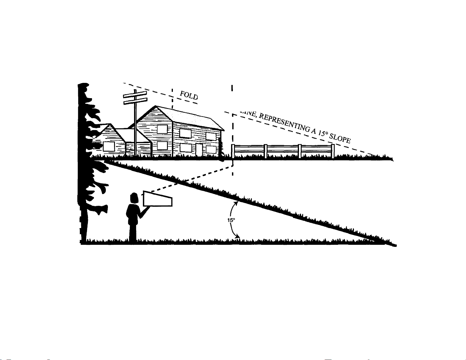
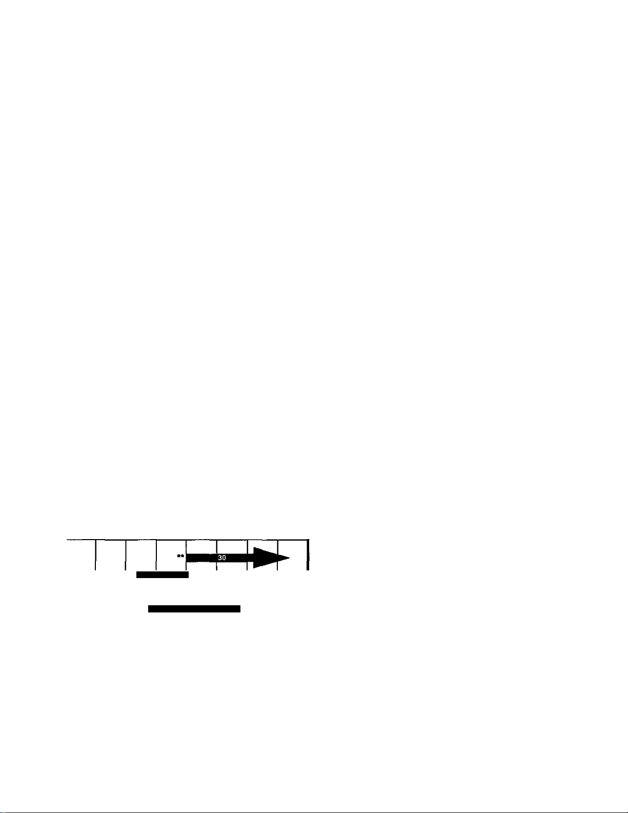
1. Fold this page along dotted line indicated above.
2. Hold page before you so that its left edge is vertically parallel to a tree trunk or other upright structure.
3. Sight across the fold in the direction of hill slope you want to measure.
4. Compare the angle of the fold with the slope of the hill.
WARNING: Do not mow on inclines with a slope in excess of 15 degrees (a rise of approximately 2.5 feet every 10
feet). A lawn utility vehicle could overturn and cause serious injury. Operate these vehicles up and down slopes, never
across the face of slopes.
3
Page 7
SETTING UP
Unpacking Unit
Remove all screws and staples from the crate.
1.
Holding sides of the crate firmly, lift top. of the crate
2.
up and set it aside. Avoid tire punctures.
Remove and discard plastic bag covering the unit.
3.
Lift the rear of the vehicle off the crate. Repeat for
4.
the front. This may require two people.
Remove plastic bag and its contents (owner’s
5.
manual, ignition keys etc.) that are packed on the
steering shaft.
Refer to Figure 7 in Owner's Manual for location of
6.
the parking brake. Check to make sure that the
parking brake is disengaged so that the vehicle can
be rolled fonward.
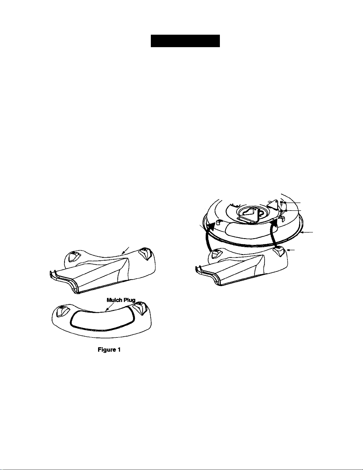
Loose Parts
Remove loose parts from the grass catcher and/or
1.
the crate very carefully. Compare with list below
and part illustrations in Figure 1.
Mulch plug
Side-discharge chute
Plastic bag carrying operator's manual and two
ignition keys(not shown)
1. Lower tile cutti ng deck to the lowest position by
sliding the deck lift lever to the appropriate slot
indicated by the label. Refer to Figure 7 and
description on page 9 for more details.
2. Remove the thumb screw and flat washer attaching
the two ends of the grass catcher chute to the deck.
Slide the grass catcher chute out of the vehicle
housing; remove and save the hardware.
3. Place the side-discharge chute on the deck so tiiat
the two holes on its two ends align with the two
holes on the deck where the grass catcher chute
was attached. See Figure 2.
4. Insert a thumb screw and a flat washer, removed in
step 2, through the left hole on the chute and the
corresponding hole on the deck. See Figure 2.
Thread the screw a few turns to secure, but do not
tighten at this time.
5. Repeat on the right side. Tighten both screws.
Thumb
Screw
Rat Washer
Deck
NOTE: Any reference in this manuai to RiGHT, LEFT,
TOP and BOTTOM of the tractor is observed from the
operators position when sitting on the vehicie seat.
Attaching Side-Discharge Chute
WARNING: Do not mow grass if any one of
A
the grass catcher chute, discharge chute or
mulch plug is not firmly installed on the lawn
utility vehicle.
Side-Discharge
Chute
Figure 2
Attaching Mulch Plug
To mulch grass and recirculate clippings back to the
lawn, attach the mulching plug to the deck.
1. Lower the cutting deck to the lowest position.
2. Remove the thumb screw and flat washer attaching
the two ends of the discharge chute to the deck.
(Refer to Figure 2 for the discharge chute set-up.)
Slide the discharge chute out of the deck housing;
remove and save the hardware.
3. Place the mulch plug on the deck so that the two
holes on its two ends align witii the two holes on the
deck where the discharge chute was attached.
4. Insert thumb screw and flat washer, removed in
step 2, through the left hole on the mulch plug and
corresponding hole on the deck. See Figure 3.
Thread the screw a few turns to secure, but do not
tighten at this time.
5. Repeat on tine right side. Tighten both screws.
Page 8
Thumb Screw
Rat Washer
Deck
Mulch Plug
Figure 3
NOTE: The grass bag must be in positior), on the
vehicle, for any kind of mowing operation, including
mulching and side-discharge of grass clippings.
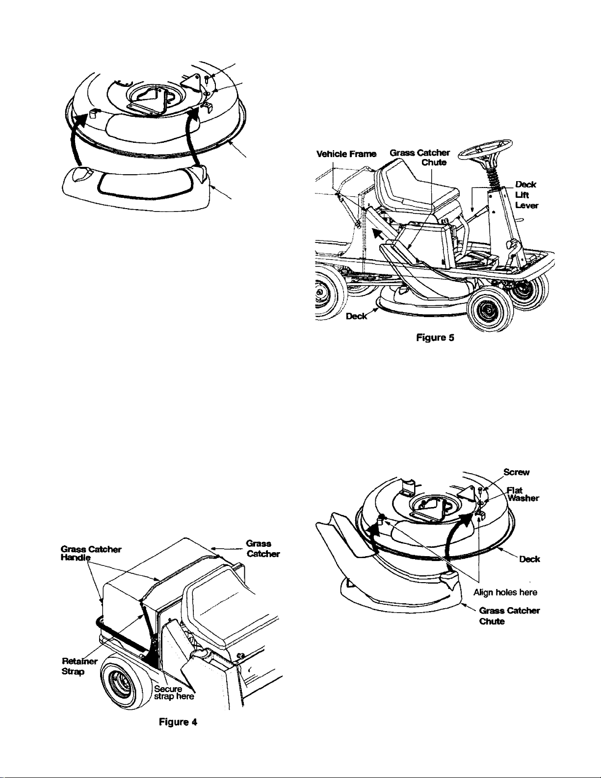
Attaching Grass Catcher
The grass catcher is assembled at the factory and
attached to the vehicle for shipping convenience. The
grass catcher has to be attached to the vehicle only
when cutting grass and/or bagging the grass clippings.
If the grass catcher was removed from the unit for some
reason, re-attach by following instructions below.
1. Hold the grass catcher by the two handles and slide
it on top of the utility bed at the back of the vehicle.
Make sure that the side of the grass catcher with
the opening is aiigned with the vehicle frame
behind the seat.
2. Pull the two retainer straps on two sides of the
grass catcher and attach loose ends of №e strap to
the respective hook on the frame of the vehicle.
See Figure 4.
Grass Catcher Chute
1. Piace the cutting deck in the lowest position by
sliding the deck lift lever to the appropriate slot.
Slide the elbow of the grass catcher chute through
2.
the vehicle frame and align the chute opening with
the corresponding opening on the vehicle frame.
See Figure 5.
Align the two holes on the other end of the chute
3.
with the two comesponding holes on the deck. See
Figure 6.
4.
Insert thumb screw and flat washer, removed
earlier, through the left hole on the grass catcher
chute and corresponding hole on the deck. Thread
the screw a few turns to secure, but do not tighten.
See Figure 6.
5.
Repeat on the right side. Tighten both screws.
Thumb
NOTE: The bag switch will automatically shut off the
engine if the grass catcher is not attached to /he unit
while cutting grass. Do not remove the bag even when
using the mulch plug or the side-discharge chute.
Figure 6
Removing Grass Catcher
1. Unhook frie two retainer straps securing the grass
catcher to the frame of the vehicle.
2. Holding the grass catcher firmly by the handle, slide
it slightly upward and outward to remove.
Page 9
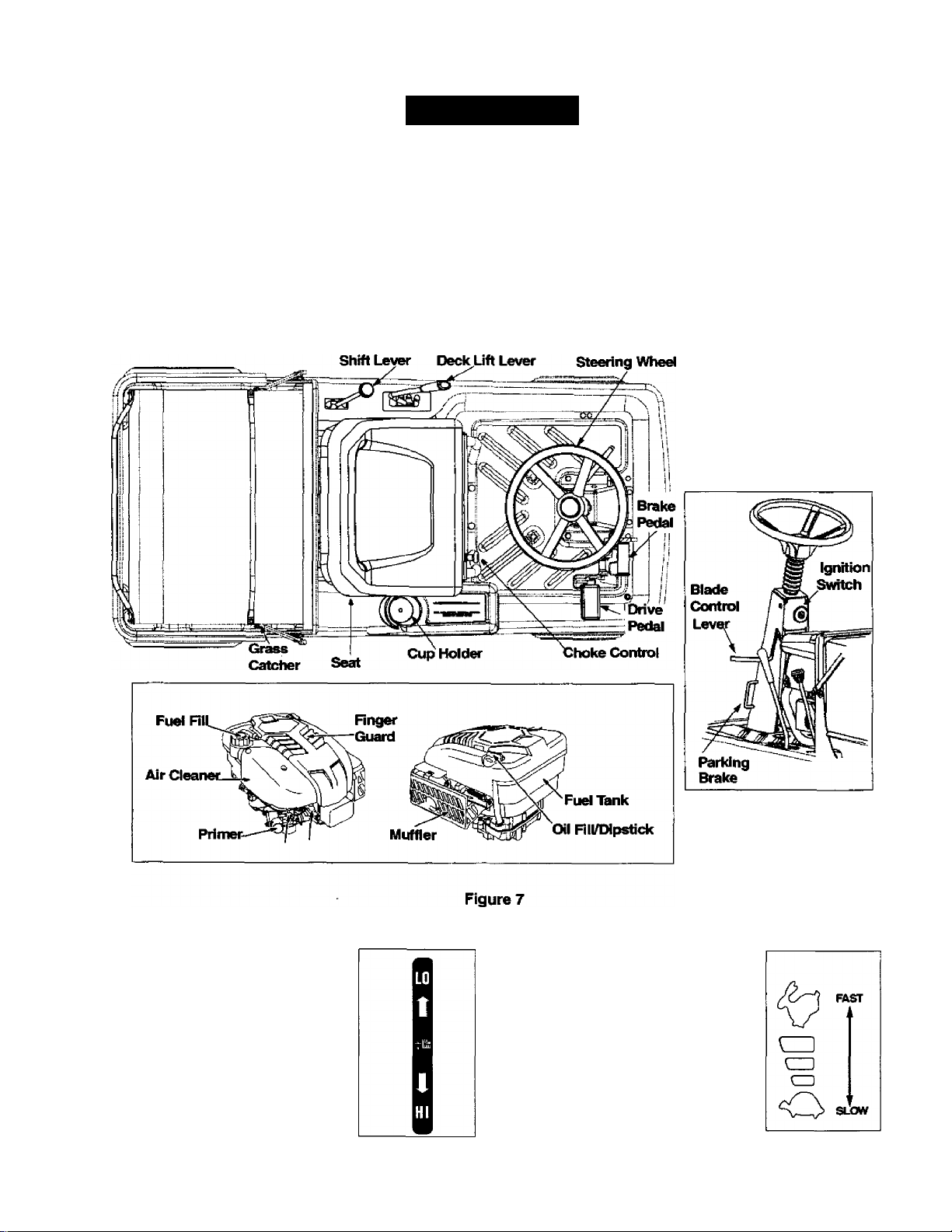
OPERATION
Know Your Lawn Utility Vehicle
The Lawn Utility Vehicle is meant to be used as both a riding lawn mower and a utility cart. Its grass collector can be
easily removed to expose the utility bed. Compare the illustrations in Rgure 7 with your lawn utility vehicle to learn
about the location and features of its various controls.
WARNING: The operation of any riding mower can result in foreign objects being thrown into the
dk
operator’s eyes, causing severe eye damage. Always wear safety glasses while operating the mower, or
performing any adjustments or repairs on it.
Deck Lift Lever
This lever is located on the left
fender of the vehicle and adjacent to
the shift lever. It is used to change
the height of the cutting deck. Move
the lever to the right and slide it to
the position desired. Make sure it is
firmly placed in the notch intended.
Follow the label on the unit
indicating the cutting height
positions.
Drive Pedal
The drive pedal is located on the
right front side of the unit adjacent to
the brake pedal. Ground speed is
controlled by depressing this pedal
— the further down the pedal is
depressed, the faster the vehicle will
move. The pedal returns to its
original position when not
depressed. For further details, see
next section.
Page 10
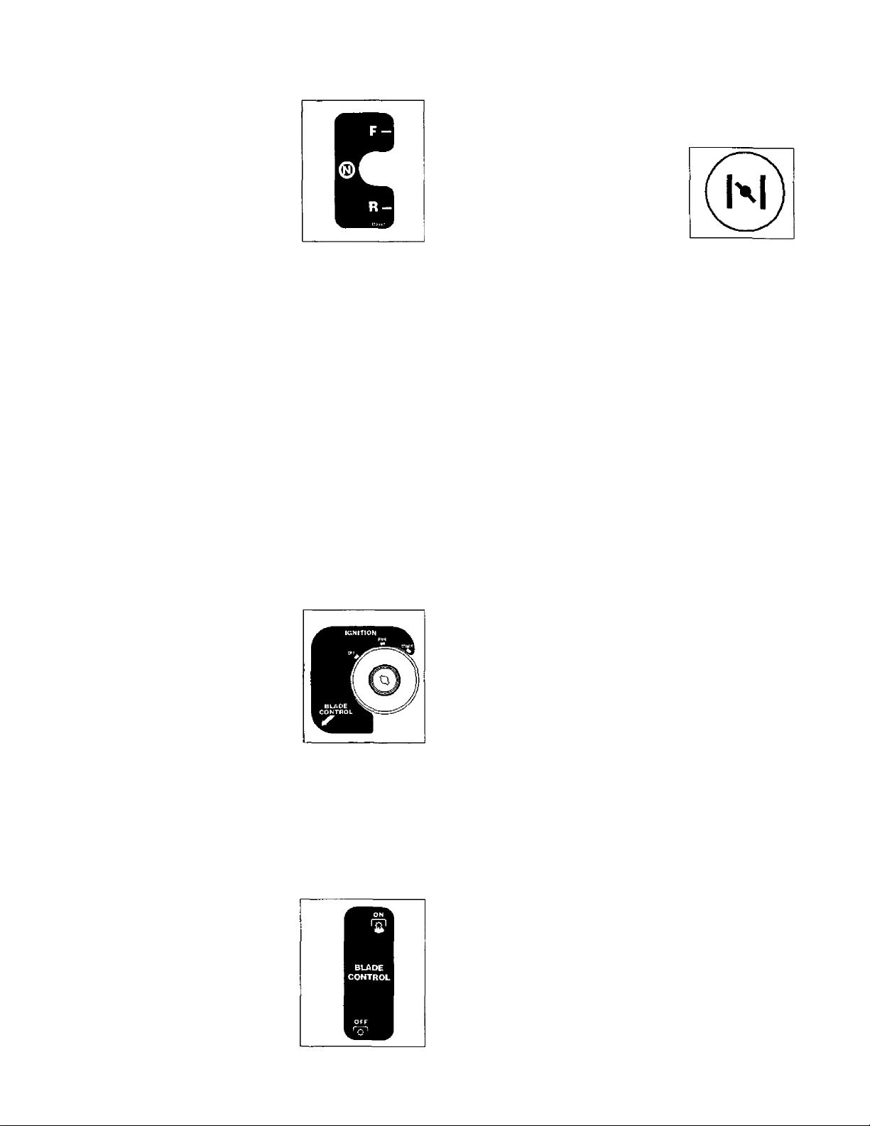
Shift Lever
This lever is located on the left
side of the fender and has three
clearly marked positions:
FORWARD (F), REVERSE (R)
and NEUTRAL (N). Follow the
label on the unit to place the shift
lever in the position desired.
IMPORTANT: The brake pedal
must be depressed completely
and the vehicle not in motion while sliding the shift lever
to another position. Neverforce the shift lever to avoid
damage to the transmission.
Parking Brake
The parking brake has to be set
(1) to park the vehicle, or (2) to
leave the engine running when
the operator leaves the seat.
Depress the brake pedal
completely and push the parking
brake lock to activate it. Once the
parking brake is locked, you can
take your foot off the brake pedal.
To release the parking brake,
depress the brake pedal lightly.
IMPORTANT: Always set the parking brake when leaving
the vehicle unattended.
PARKING
BRAKE
LOCK
Ignition Switch
This switch is located on the
steering column and is used to
start the engine. Insert key into
slot and turn clockwise to START
position indicated by the label on
the switch. Once the engine has
started, release the key and it will
return to RUN position. To shut
engine off, move shift ieverto (N),
set the parking brake and turn key to the OFF position.
Cup Holder
This vehicle offers the convenience of carrying your
beverage while working. The cup holder is located on
the fender to the right of the seat above the battery.
Blade Control Lever
This lever is iocated on the left
side of the vehicie next to the
steering wheel. Move the blade
control lever to ON position to
engage power to the cutting
deck, and move it to OFF to
disengage.
IMPORTANT: The blade control
lever must be in the disengaged
(off) position when (1) starting the engine, (2) travelling
in reverse, and (3) if the operator ieaves the seat.
Choke Control
This is located in front of the seat
frame. Pull the choke control
outward to activate choke for
starting engine; push it inward once
the engine starts.
Brake Pedal
This pedal is located on the right front side of the unit
and to the left of the drive pedal. It is used for sudden
stops and/or for setting the parking brake. The brake
pedal must be fully depressed to activate the safety
interlock switch when starting the vehicie.
Safety Interlock
This unit is equipped with a safety interlock system for
your protection. The safety switches are connected to
the brake pedai, the steering column, the shift iever,
and the seat and will shut off the engine automatically
under certain conditions. These conditions are
described below. Read this section and be aware of ttie
purpose of this safety mechanism at all times; do not
tamper with its working.
WARNING: To avoid serious injury, do not
dk
The purpose of the safety interlock system is four-fold:
Seat Switch: This switch is iocated under the seat and
is a safety mechanism. When the parking brake is
disengaged and blade control lever engaged, the
operator must remain seated at all times for the engine
to run. If he/she leaves the seat without disengaging
blade control lever and turning engine off, this switch
will automatically shut the engine off regardless of
whether the parking brake is engaged.
Reverse Switch: This switch is located near the shift
lever and will automatically shut off the engine if the
blade control lever is moved to (ON) position when the
shift lever is in (R). That is, the vehicle will not move in
reverse direction with the blade control lever engaged.
operate the riding mower if the safety interlock
system is malfunctioning.
a.
to prevent the engine from starting uniess the
brake pedal is depressed;
to shut off the engine if the blade control lever is
b.
not disengaged when the shift lever is put into
reverse;
to shut the engine off when the operator leaves
c.
the seat without engaging the parking brake;
to shut the engine off if an attempt is made to
d.
cut grass without the grass catcher properly
attached to the unit.
10
Page 11
Brake Switch: This switch is located under the brake
pedal assembly. The engine will not start witiiout first
depressing the brake pedal. This switch will also shut
off the engine if the operator attempts to get off the unit
without setting the parking brake.
Blade Control Switch: This switch is located in the
steering column. If the operator attempts to start the
engine, get off the seat or remove grass bag with the
blade control lever still engaged, it will shut engine off.
Grass Bag Switch: This switch is located in the
bulkhead behind the engine. If the operator attempts to
cut grass when the grass catcher is not property
attached to the vehicle, it will shut engine off.
Before Starting
Filling Up Oil
Check oil level in the engine oil sump before starting the
engine. (Oil sump capacity: 22 ozyo.65 liter)
1. Place the vehicle on level ground and flip the seat
up to access the engine.
2. With a dry rag, clean the area around the oil fill on
the engine.
3. Remove dipstick and wipe it clean with cloth.
4. Replace and tighten the dipstick. Remove the
dipstick again and check the oil level mark on it.
The oil level should be at FULL line on the dipstick.
If the level is short of that, add oil to the oil fill slowly.
Recheck the oil level on the dipstick. If needed, add
more oil. Do not overfill.
NOTE: The lawn utility vehicle is shipped with oil in the
engine crankcase.
5. Place the dipstick in position and tighten to secure.
Type of Oil
1. Refer to the chart above for proper grade of oil.
2. Use a high quality detergent oil classified “For
service SF, SG,SH, SJ” or higher.
3. Do not use special additives.
NOTE: SynUietic oil meeting ILSAC GF-2, API
certification and API service symbol with “SJ/CF
Energy Conserving" or higher is an acceptable oil at all
temperatures. Use of syntiietic oil does not alter
required oil change intervals.
Filling Up Gasoline
WARNING: Fill fuel tank outdoors or in well-
A
NOTE: On a vehicle which has already been started
and/or operated once immediately prior to this gasoline
fill-up, turn engine off and let cool at least two minutes
before removing gas cap.
1.
2.
ventilated area, away from sparks, open
flames, pilot lights, heat and other ignition
sources.
Remove gas tank cap and fill tank to approximately
1.5 inches below top of neck to allow for fuel
expansion. Be careful not to overfill.
Replace cap on the gas tank and tighten to secure.
If fuel spills on part of engine or vehicle, wait until it
evaporates before starting engine.
Type of Gasoline
• Use clean, fresh, regular unleaded gasoline with
minimum 85 octane rating.
• Do not use gasoline mixed with methanol, or
gasoline which has been stored for more than 30
days. Always purchase fuel in quantity that can be
used up wi№in 30 days. Fresh fuel prevents gum
from forming in the fuel system or on carburetor.
• Do not mix gasoline with engine oil.
SÄE Viscosity ärades
5W-30, 10W-30I
Synthetic 5W-30.10W-30
"F-20° 20°
Starting temperature range anticipateci before next oil change
* CAUTION: Air cooled engines run hotter than automotive
engines. The use of non-synthetic multi-viscosity oils (5W30,10W-30 etc.) in temperatures above 40“F will result in
higher than normal oil consumption. When using a multi
viscosity oil, check oil level more frequently.
CAUTION: SAE 30 oil, if used below 40°F, will result in
hard starting and possible engine bore damage due to
inadequate lubrication.
-L
,40°
32
60°_L80° 100°
_L
NOTE: Some fuels, called oxygenated or reformulated
gasoline, are blended with alcohols or ethers. Using
these blends frequently can damage the fuel sysfem or
affect performance. If engine performance is affected,
use gasoline with lower percentage of alcohol or ether.
Starting the Engine
1. Looking under the seat and towards the front of the
engine, check tiiat spark plug wire is connected.
2. Occupy the seat and insert key into ignition switch.
3. Place blade control lever in OFF position. (Refer to
Figure 7 for location of controls mentioned here.)
4. Engage parking brake.
5. Puli choke control outward into the Choke position.
6. Turn ignition key clockwise to START position.
After the engine starts, release the key. It will return
to RUN position automatically.
11
Page 12
NOTE: Do not hold the key in the START position for
longer than ten seconds at a time. Doing so may cause
damage to your vehicie engine’s electhc starter.
7. After the engine starts, press choke control inward,
thus closing the choke. See Figure 8.
NOTE: Do not ieave the choke controi on white
operating the unit. Doing so witi resuit in a “rich" fuel
mixture and cause the engine to mn poorly.
Choke Corrtrol
Figure 8
• To move in reverse: Place blade control lever in
OFF position. Place shift lever in the (R) position,
check that the area behind is clear and then siowly
depress the drive pedal.
• To drive on slopes: Refer to Slope Gauge on
page 6 to determine slopes or inclines where you
can operate your unit safely. Do not operate the
vehicle if the gauge indicates a steep incline.
Stopping the Vehicle
1. Release drive pedal and depress brake pedal.
2. When the mower comes to a complete stop, place
the shift lever in neutral.
3. Continue to depress the brake pedai while you
push the parking brake. Take you r foot off the brake
pedal when the parking brake is locked.
4. Tum ignition key to OFF position and remove key.
NOTE: Do not leave key in fhe ON position when you
are not operating the mower. Such action wiii drain the
battery dead.
Emergency Stopping
To stop the vehicle immediately in an emergency, raise
your body up and off the seat.
Operating the Vehicle
1. Follow instructions to start the engine.
2. Put the deck at the highest cutting position by
sliding the deck lift lever to the appropriate position.
3. Move the blade control leverto ON position.
4. If mowing grass, adjust the deck to the cutting
height desired.
5. Depress brake pedal to disengage parking brake.
6. Place shift lever In either (F) or (R) position as you
desire. Look to the rear and check before
reversing the vehicle.
IMPORTANT: Do not move the shift lever when the
vehicle is tn motion. Always use brake pedal to bring
the vehicle to a complete stop before moving shift lever.
7. Release the brake pedal and gradually depress the
drive pedal.
WARNING: Do not leave the seat of the
A
vehicle without first placing ttie blade control
lever in the disengaged (OFF) position,
depressing the brake pedal and engaging the
parking brake. If leaving the unit unattended,
also turn the ignition key off and remove key.
WARNING: Avoid sudden starts, high speed
and sudden stops.
To move forward: Place the shift lever in tfie (F)
position, then slowly depress the drive pedal until
the desired speed is achieved.
Using as Mower
• Do not mow at high ground speed, especially if a
mulch kit cr grass collector is installed.
• For best results, it is recommended that the first two
laps be cut with the discharge thrown towards the
center. Then reverse the direction to throw rest of
the discharge to the outside. This will give a better
appearance to the lawn.
• Do not cut grass too short. Short grass invites weed
growth and yellows quickly in dry weather.
• Do not attempt to mow heavy brush and weeds and
extremely tall grass. Your mower is designed to
mow lawns, not clear brush.
• Keep the blades sharp and replace blades when
worn. Refer to page 14 for blade care instruction.
WARNING: Plan your mowing pattern to
A
To Empty Grass Catcher
1. Stop the mower completely, set parking brake and
2.
3.
avoid discharge of materials toward roads,
sidewalks, by-standers and the like. Also, avoid
discharging material against a wall or
obstruction which may cause discharged
material to ricochet back toward the operator.
take ignition key out. Get off the seat.
Unhook bag straps from the mower frame. Pull up
the grass catcher bag by the two handles and carry
it to the proper disposal site.
Hold bag away from your body while emptying it.
12
Page 13
4. Replace the bag on to the mower. Hook the loose
end of the bag retainer straps to the vehicle frame
to secure the grass bag.
Using as Miilcher
This vehicle is shipped with a mulch plug to recirculate
grass clippings into the lawn. The ultra-fine clippings
are forced back into the lawn where they act as a
natural fertilizer. Observe the following for best results:
• Attach the mulch plug to the cutting deck following
instructions on page 7.
• Never attempt to mulch if the lawn is damp. Wet
grass tends to stick to the underside of the cutting
deck preventing proper mulching of the clippings.
• Do not attempt to mulch more than 1/3 the total
height of the grass or approximately 1 -1/2 inches.
• Maintain a slow ground speed to allow the grass
clippings more time to be effectively mulched.
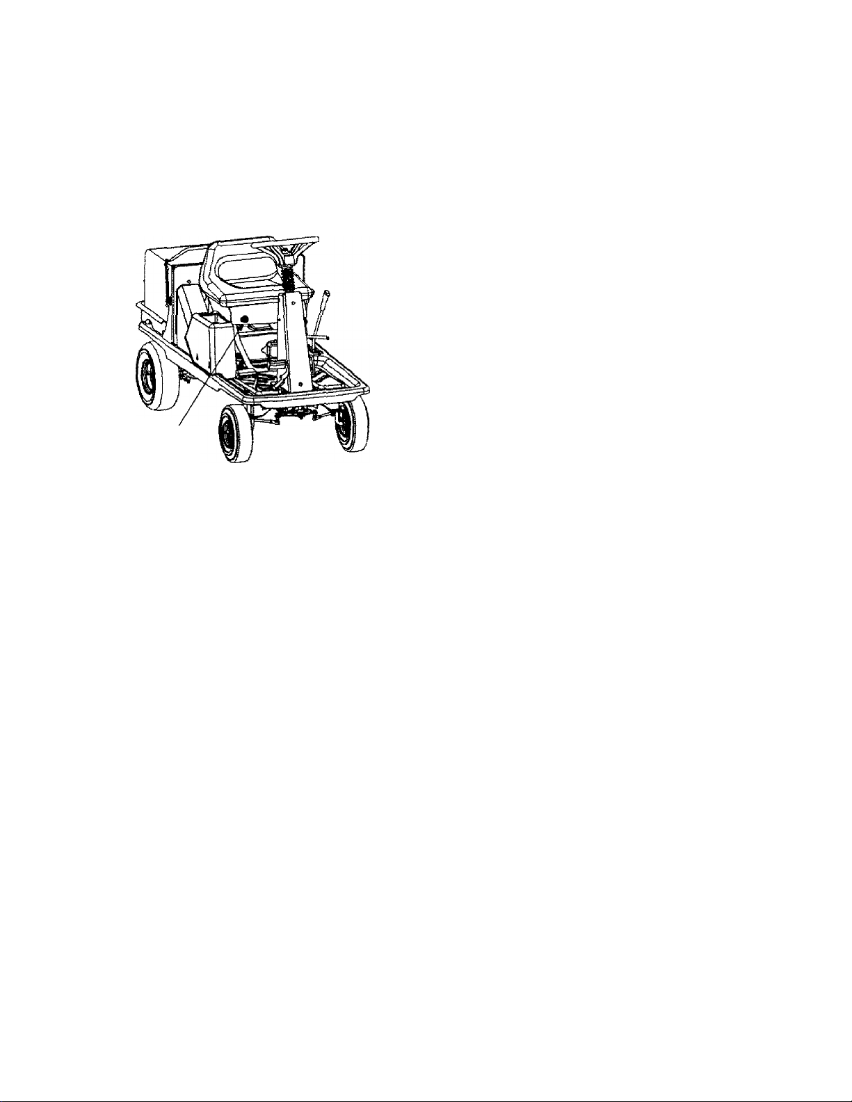
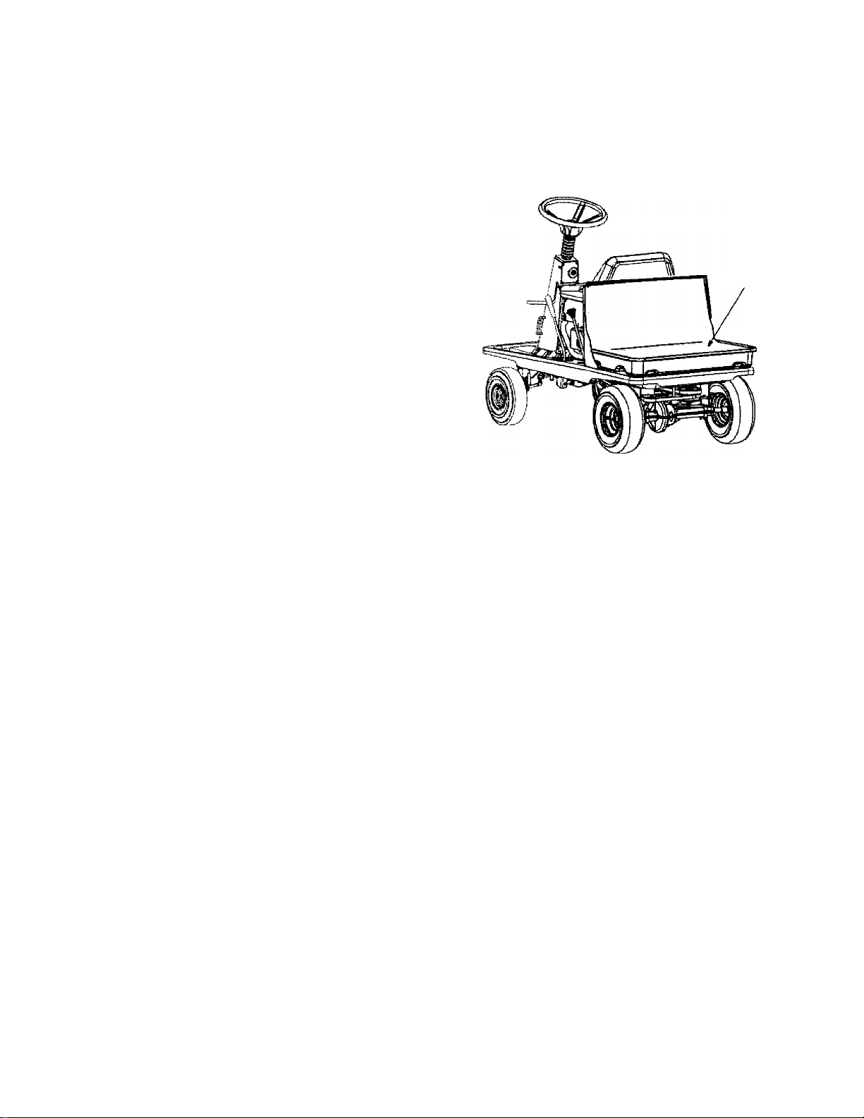
Using as Utility Cart
The lawn utility vehicle, as its name suggests, can be
used as both a riding lawn mower and a utility cart.
• Remove grass catcher to expose the utility bed.
See Figure 9. Follow instructions on page 7 for
grass catcher removal. Exercise caution in driving
the vehicle when hauling things on its utility bed.
NOTE: Total load capacity, including operator, should
not exceed 400 lbs.
Utility
Bed
Figure 9
13
Page 14
MAINTENANCE
General Recommendation
• Always observe safety rules when performing any
maintenance.
• The warranty on this lawn utility vehicle does not
cover items that have been subjected to operator
abuse or negligence. To receive full value from the
warranty, operator must maintain the equipment as
instructed in this manual.
• We do not recommend the use of pressure
washers or garden hose to clean your unit. These
may cause damage to electrical components,
spindles, pulleys, bearings or the engine. The use
of water may shorten life of your lawn utility vehicle
and reduce its serviceability.
• Follow the schedule below to ensure best
performance by your lawn utility vehicle.
Maintenance Schedule
Task to be perfonned
Engine;
Check oil level
Every 8
hours of
operation
Every 2S
hours of
operation
At start of
season
WARNING: Never attempt any maintenance
A
job without first disconnecting the spark plug
wire and grounding against the engine.
Removing Deck
1. Place the blade control lever in the disengaged
(OFF) position and engage the parking brake.
Lower the cutting deck to the iowest position.
2.
Disconnect spark plug wire and ground.
3.
Remove all three hairpin clips and flat washers that
4.
secure the cutting deck to the hanger links. See
Figure 10.
Slide the deck to the left to disengage it from the
hanger pins, and allow it to drop to the ground.
Remove belt from around spindle pulley.
To attach the deck to the mower, align the deck
with the hanger pins and insert the three hairpin
clips removed earlier.
Remove hairpin clip & washer
Change oil
Service air cleaner
Service spark plug
Clean debris
Clean cooling fins
Equipment:
Clean equipment
Check/sharpen blade
Lubricate pivot points
Lubricate front wheels
Lubricate steering shaft
Check brake
Check condition of belts
Check tire pressure
Check battery fluid level
V
✓
Remove hairpin clips & washers
0
Remove deck from the hangers
Figure 10
Cutting Blade
WARNING: Protect your hands by wearing
A
Removal
✓
7
1. Remove deck from beneath the vehicle. Gently flip
2. Place a block of wood between the deck housing
heavy gloves or by using a rag to grasp the
cutting blade. Avoid personal injury.
the deck over to access the blade and the spindle.
baffle and the cutting blade to act as a stabilizer.
14
Page 15
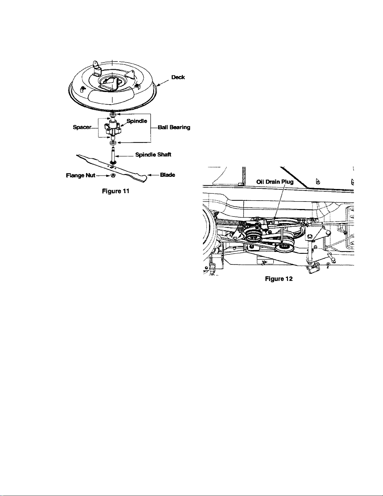
Remove the 5/8" hex flange nut which holds the
3.
blade to the blade spindle and the spindle shaft.
Remove blade from the spindle. See Figure 11.
4.
Sharpening
1. When sharpening the blade, follow the original
angle of grind as a guide. It is extremely important
that each cutting edge receives an equal amount of
grinding to prevent an unbalanced blade. An
unbalanced blade will cause excessive vibration
when rotating at high speeds, may damage the
mower and/or cause personal injury.
2. Test the blade for balance by balancing it on a
round shaft screwdriver. Remove metal from the
heavy side until it balances evenly.
Maintaining Engine
Changing Engine Oil
Disconnect spark plug wire and ground against
1.
engine.
Place the blade control lever in the disengaged
2.
(OFF) position and engage the parking brake.
Remove cutting deck by removing the three hairpin
3.
clips and flat washers that hold the deck to the
hanger links.
Making sure that all three belts are out of the way.
4.
carefully unscrew the oil drain plug and collect
spent oil in a container. Hold the container close to
the drain plug to avoid spillage. See Figure 12.
Reinstall drain plug and reattach the cutting deck.
5.
Refill with fresh engine oil. For instruction, refer to
6.
page 11, Filling Up Oil.
Reassembly
1. Before reassembling the blade to the unit, lubricate
the spindle shaft with light oil (or engine oil).
2. Be sure to properly align "star” fitting on blade with
"star” on spindle shaft.
NOTE: When replacing the blade, be sure to install the
blade with the side marked “Bottom” (or with part
number) facing the ground when the mower is in the
operating position. Also make sure that the entire biade
and spindle assembly is reattached in the right order.
See Figure 11.
3. Place the flange nut, removed earlier, and secure
blade firmly to the spindle. Blade Mounting
Torque: 95-122 N-M or 70-90 ft.-lb. maximum.
4. Flip the deck back to its operating position and
reattach to the mower. Secure the deck to the deck
hanger links by three hairpin clips and flat washers
removed earlier.
NOTE: To ensure safe operation, all nuts and bolts
must be checked periodically for correct tightness.
WARNING: Make sure not to spill oil on the
àk
belts while draining spent oil or removing the oil
container.
Changing Air Cleaner
The engine on your lawn utility vehicle has an oval air
cleaner cartridge and a pre-cleaner. See engine parts
list starting on page 37 of this manual for the part
numbers. Regular maintenance of the air cleaner will
improve your vehicle’s engine performance and extend
life of the engine.
1. Service the air cleaner at the start of the season,
and every 25 hours of operation. You will have to
clean it more frequently if it is operated in extremely
dusty conditions. Replace air cleaner parts if these
are very dirty.
Disconnect spark plug wire and ground against
2.
engine.
Place the blade control lever in the disengaged
3.
(OFF) position and engage the parking brake.
4. Pivot the seat up and access the engine.
IS
Page 16
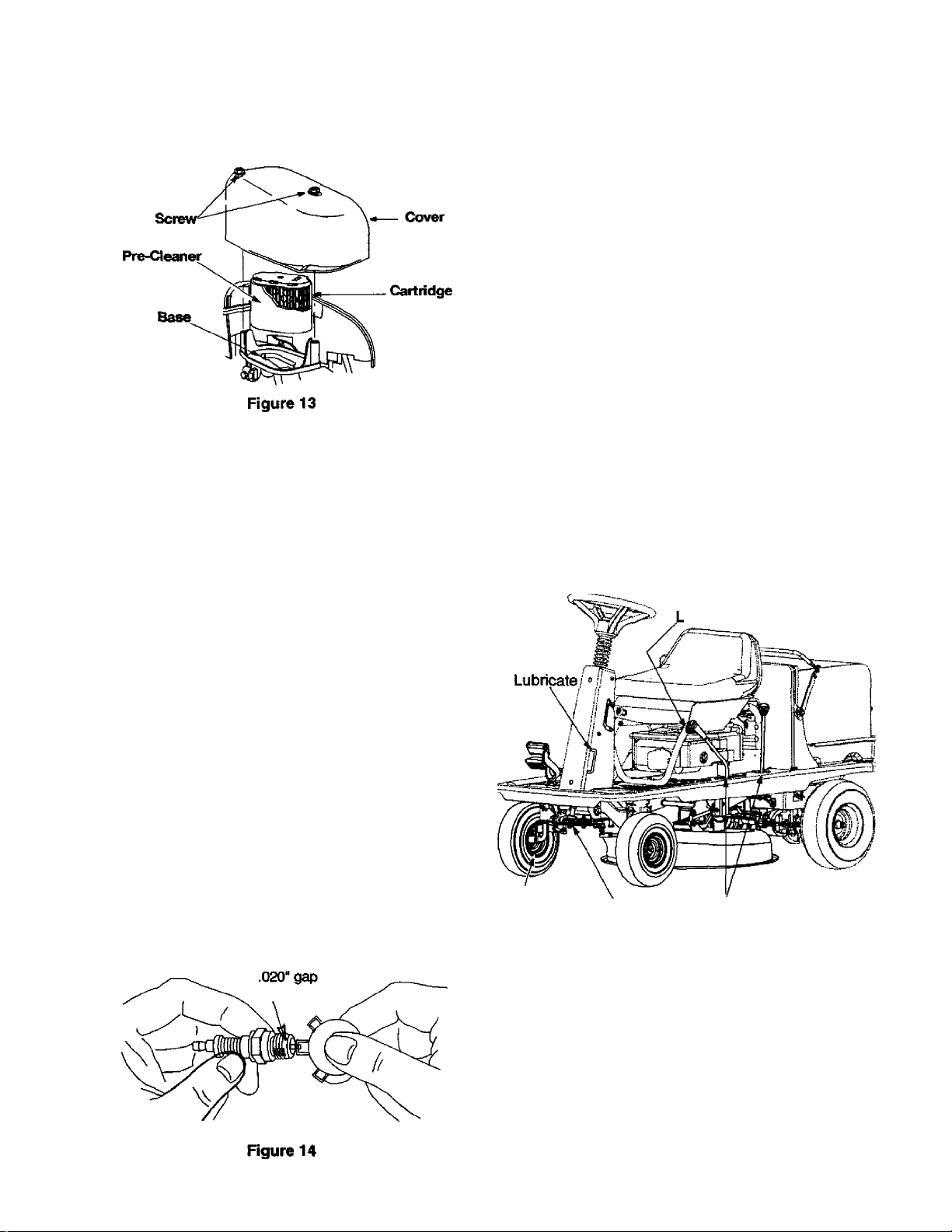
Completely loosen the two screws that hold the
5.
cover of the air cleaner. Remove the entire air
cleaner assembly from the base. Lift the cover off
the air cleaner, ^e Figure 13.
Engine Tune-Up Specifications
• Armature air gap
• Spark plug gap
0.006 - 0.014 inches
0.020 inches
To clean cartridge, gently tap pleated paper side on
6.
a flat surface.
7.
To clean pre-cleaner, separate it from the cartridge
and wash in liquid detergent and water. Air-dry
thoroughly. Re-assemble the dry pre-cleaner on
the cartridge.
WARNING: Do not use pressurized air or
A
8.
9.
solvents to clean carbidge. Pressurized air can
damage cartridge while solvents will dissolve it.
Install clean (or new) air cleaner assembly in base
so that the lip of the cartridge sits inside the base.
See Figure 13.
Place the cover over the air cleaner assembly and
secure with the two screws loosened in step 5.
• Intake
• Exhaust
0.004 - 0.006 inch
0.009-0.011 inch
Lubrication
See Figure 15 for an illustration of the lube points
described below.
• Blade Assembly: Lubricate blade assembly and
deck spindle before reassembling the blade either
after sharpening or replacement.
• Pivot Points; Lubricate all pivot points on the drive
system, parking brake and lift linkage at least once
a season wi№ light oil.
• Steering Shaft: Lubricate steering shaft and gear
spline at least once a season w№ light oil.
• Gear: Lubricate teeth of the external steering gears
with automotive multi-purpose grease every 25
hours of operation or once a season.
• Front Wheels: Lubricate the front wheels wifri
automotive grease once a season.
ubricate
Spark Plug
1. Clean area around the spark plug base.
2. Remove and inspect the spark plug.
3. Replace the spark plug if electrodes are pitted,
burned, or the porcelain is cracked. See Figure 14 .
4. Clean the spark plug and reset the gap to 0.020'' at
least once a season or every 100 hours of
operation. See Figure 14. Replace if necessary.
Refer to parts list section for part number.
NOTE: Do not sandblast spark plug. Spark plug should
be cleaned by scraping or wire brushing and washing
with a commercial solvent.
Lubricate .
Lubricate Lubricate
Figure 15: Lubrication Chart
Brake
During normal operation of any vehicle, the brake is
subject to wear and tear. Check the brake every 25
hours of operation by carrying out the following test:
1. Release the parking brake and place the shift lever
in neutral. Depress the brake pedal and try to roll
the vehicle. It should not move. If the vehicle
moves, adjust the brake following instructions on
page 20.
16
Page 17
2. Set the parking brake and push the vehicle. If the
rear wheels roll, adjust the brake following
instructions on page 20.
Tires
WARNING: Never exceed meiximum limit of
àk
The recommended operating tire pressure is 20-22 psi
for both sets of tires. Refer to the tire sidewaii for exact
tire manufacturer’s recommendation. Do not
overinflate. Uneven tire pressure could cause the
cutting deck to mow unevenly.
air pressure shown on sidewall of the tire.
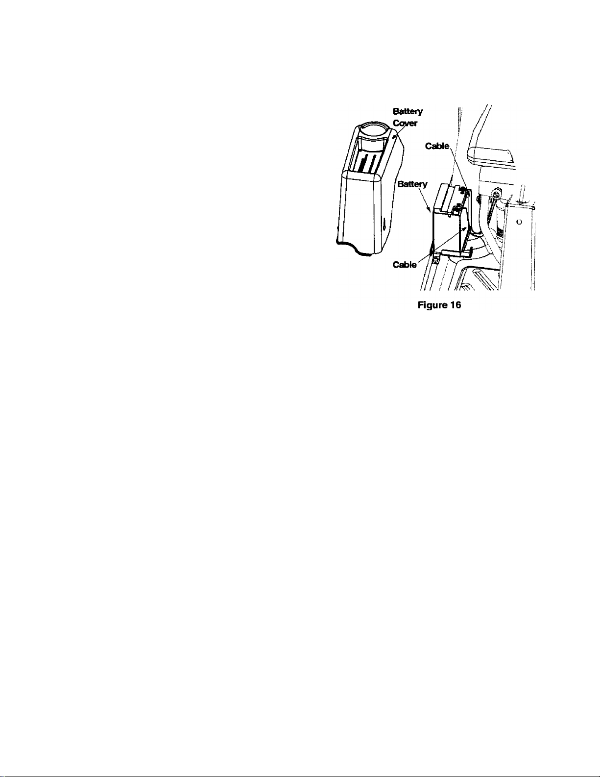
Battery
The battery is located under the cup holder to the right
of the seat. The positive battery terminal is marked Pos.
(+). The negative battery terminal is marked Neg. (-).
WARNING: Battery posts, terminals and
A
• Always keep battery cables and terminals clean
• After cleaning, apply a light coat of petroleum jelly
• Always keep the rubber boot positioned over the
• If removing the battery for any reason, disconnect
iMPOFtTANT: Be certain that wires are connected to the
correct terminals; reversing them could change polarity
and cause damage to the engine’s alternating system.
• Check fluid level inside each cell of the battery
• Add only distilled water. Never add additional add
NOTE: If you have operated the tractor for a long
period, check the fluid level of the battery as it can
overheat and lose fluid.
Connecting Battery Cables
To reconnect battery cables, if the battery was removed
for some reason, follow instructions below.
related accessories contain lead and lead
compounds. Wash hands after handling.
and free of corrosive build-up.
or grease to both terminals.
positive terminal to prevent shorting.
the NEGATIVE (black) wire from its terminal first,
followed by the POSITIVE (red) wire. When re
installing battery, always connect the POSITIVE
(red) wire to its terminal first, followed by the
NEGATIVE (black) wire.
every two weeks and before and after charging.
Always maintain level just below the split rings.
or any other chemicals to the battery after initial
activation.
Remove three screws holding the cup and battery
1.
holder to the frame of the unit.
Remove red and black insulation caps from battery
2.
terminals.
Remove battery terminal screws with a Phillips
3.
screw driver or a 10 mm. socket wrench.
Attach the red battery cable to the positive terminal
4.
(marked +), and the black battery cable to the
negative terminal (marked -) on the battery. See
Rgure 16.
Align the cables with tiie slots in the battery cover
5.
and tighten the screws on the battery terminals.
See Figure 16.
WARNING: Press the battery cables against
A
6. Re-install the battery cover and cup holder.
side of battery so tiiat these do not make
contact with flange of rider frame when it is
opened or closed.
Cleaning the Equipment
1. Promptly wipe off any fuel or oil spilled on the
machine with clean cloth.
2. Clean the underside of the blade housing after
each mowing. Do not let clippings or debris
accumulate around the blade.
3. Using a brush or cloth, remove grass, chaff or
debris from the finger guard on the engine daily to
prevent overheating of the engine. Do not dean
with a forceful spray of water since water
contaminates the fuel system.
4. Keep the governor linkage, springs and controls
free of debris.
17
Page 18
SERVICE & ADJUSTMENT
WARNING: Never attempt any adjustment
ák
Adjusting Seat Position
The seat position on the lawn utility vehicle can be
adjusted to maximize the operator’s convenience.
1. Stop the vehicle completely and engage the
2.
3.
4.
while the engine is running, except where
specified in the operator’s manual.
WARNING: For all other adjustments,
disconnect the sparit plug wire(s) and ground
against the engine first. Then proceed with the
adjustment.
parking brake. Turn ignition off.
Pivot the seat up, as shown in Figure 17, to access
seat hardware.
Using a 9/16” wrench or socket, loosen the four
self-tapping screws on the bottom of the seat. See
Rgure 17.
Slide the seat forward or backward in the slot, and
position it as desired. Retighten the four screws.
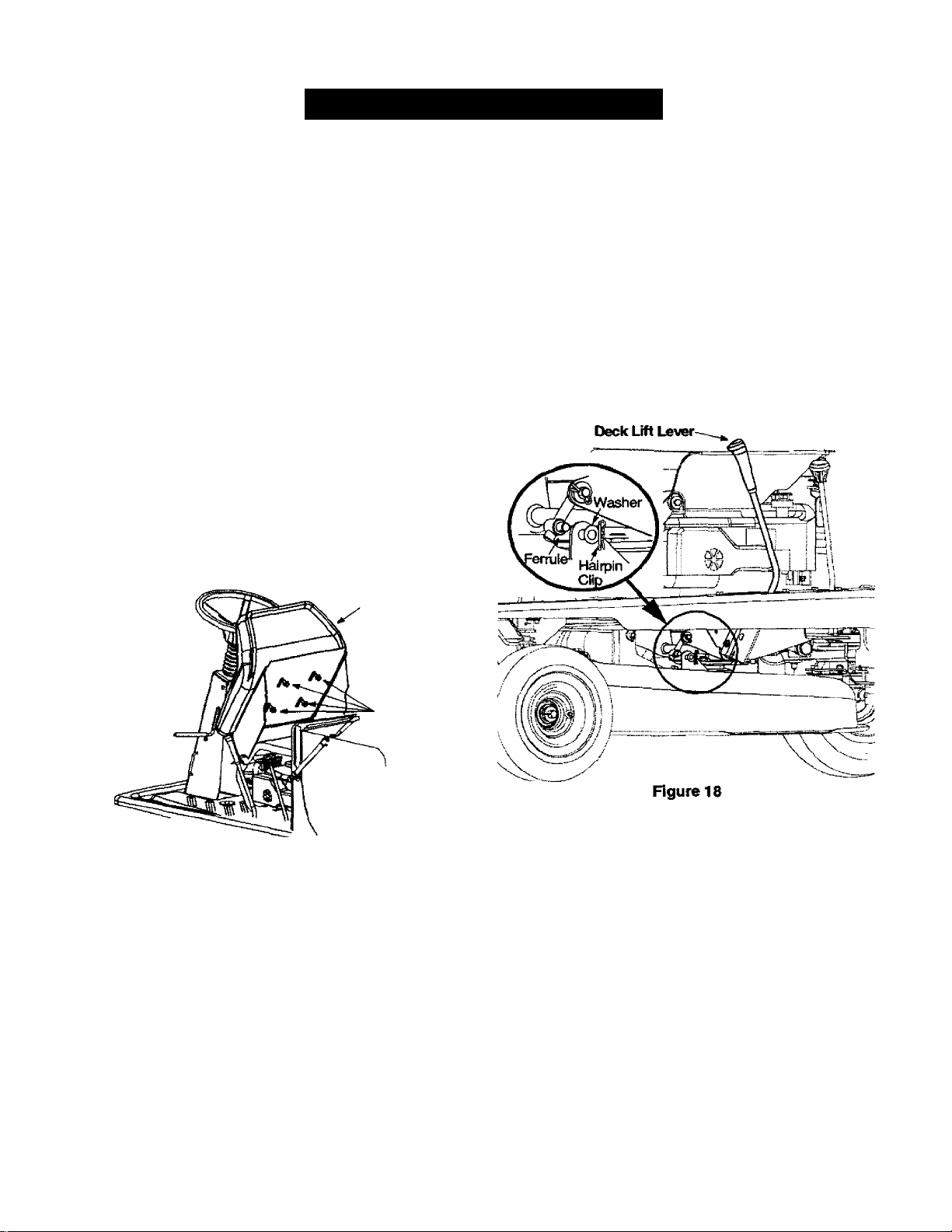
4.
Wearing a pair of heavy work gloves to prevent
injury, rotate the cutting blade so that it is pointed
side to side and perpendicular to the rider.
5.
Measure the distance from each tip of the blade to
the ground. If the distance from both blade tips to
the ground is not the same, perform a side to side
levelling of the deck.
6.
For levelling, remove the hairpin clip and flat
washer shown in Figure 18 . Thread the ferrule in or
out as required.
7.
Check for conect adjustment. Repeat adjustment if
necessary
8.
Reattach the hairpin clip and flat washer to ferrule.
Pivot seat up
Self-Tapping
Screw
Figure 17
Deck Levelling
1. In case of uneven mowng, check air pressure in all
four tires and fill up if needed. Recommended air
pressure is 20-22 psi. If this does not correct the
problem, proceed with deck levelling.
IMPORTANT: Perform adjustments to the deck on a flat,
level surface.
2.
Place the vehicle on a level surface. Depress and
lock the parking brake. Disconnect the spark plug
wire and ground it.
3.
Place the deck in the lowest cutting position by
sliding the deck lever to the appropriate position.
Deck Engagement
NOTE: The deck control cable is threaded at both ends;
adjustment has to be made at the end that attaches to
the control lever on the steering coiumn.
1. Inspect the linkage and cable for damage through
wear and tear.
2. To determine whether adjustment is necessary,
perform the following test. The deck engagement
cable is correctly adjusted when the upper deck
drive belt has a maximum deflection of 0.5" in the
engaged position. When disengaged, the blade
brake should be firmly applied and the belt should
not drag.
3. To adjust, loosen the jam nuts and back the cable
out to tighten or thread inward to loosen. Use a 1/2”
wrench for this purpose.
18
Page 19
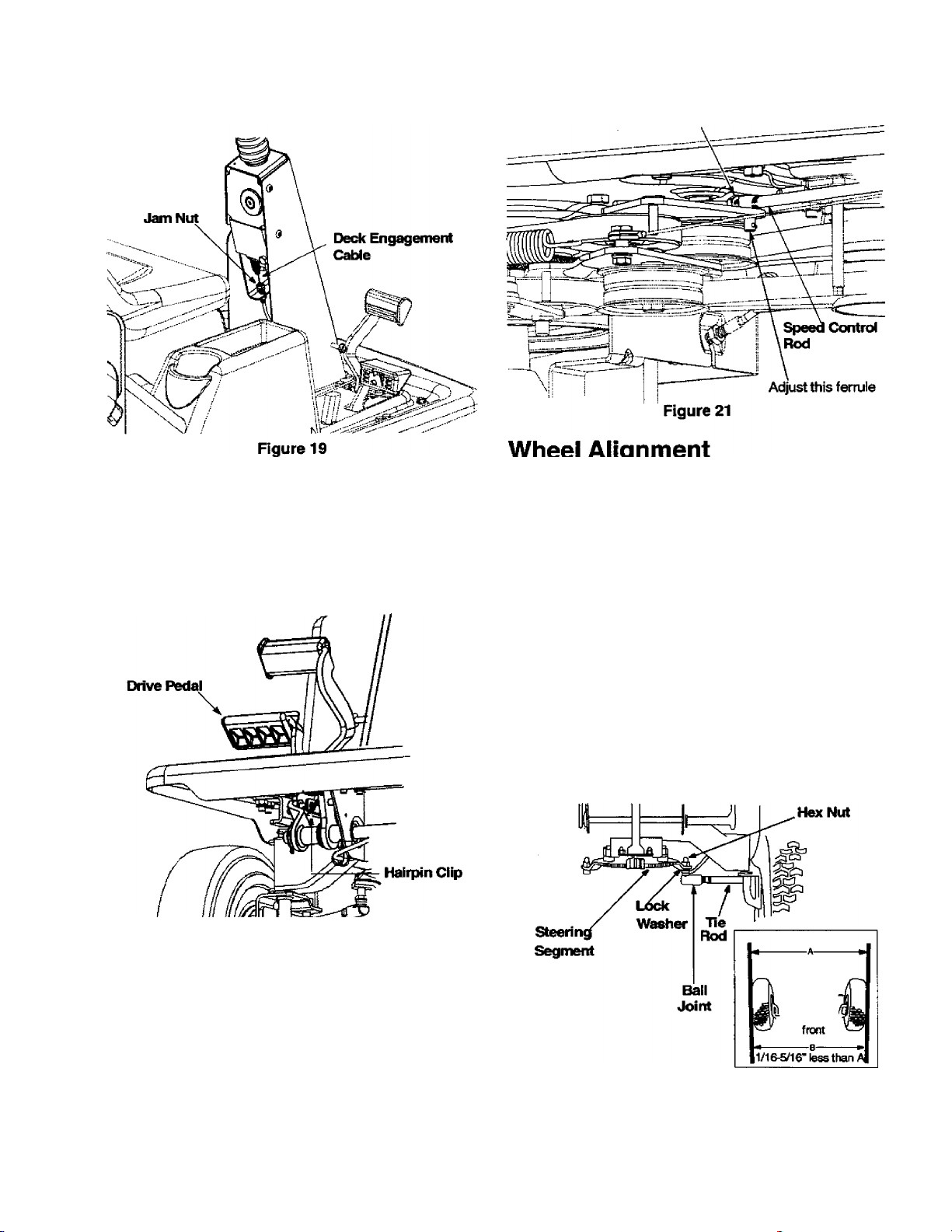
4. Retighten jam nuts when proper tension is reached.
Test the adjustment. Readjust if necessary.
JfHn Nut
Adjusting Speed Control Rod
This adjusbnent is necessary when the vehicle cannot
hold the full range of speeds, or shows belt drag
(“creep”) when the drive pedal is released.
1. Remove hairpin clip securing speed control rod to
the drive pedal assembly. See Rgure 20.
The front wheels should toe-in 1/16-5/16 inch. Toadjust
toe-in, follow these steps:
1. Using 9/16" wrench, remove the hex nut and lock
washer holding ball joint to the steering segment.
See Figure 22 . You may need to hold the jam nut
below the steering segment with a 1/2” wrench.
Loosen the jam nut on the tie rod using a 9/16”
2.
wrench. See Figure 22,
Adjust the ball joint in or out until the wheels toe-in
3.
approximately 1/16"-5/16" (Dimension “B” should
be approximately 1/16”-5/16” less than dimension
“A"). See Rgure 22 .
Replace the ball joint on to the steering segment,
4.
and tighten the jam nut on the tie rod.
Replace the hex nut and lock washer, removed in
5.
step 1, and tighten the screw.
Figure 20
2.
Remove the jam nut that secures ferrule to the
speed control rod. See Figure 21 .
3.
If the vehicle cannot attain ail speeds, thread the
rod through the ferrule towards the front of the
mower, thus shortening the rod. See Figure 21 .
4.
If the vehicle shows belt drag, thread the rod
through the ferrule towards back of the vehicle,
thus lengthening the rod. See Rgure 21 .
5.
Tighten the jam nut.
6.
Run the vehicle to check for speed. Readjust if
necessary.
Figure 22
19
Page 20
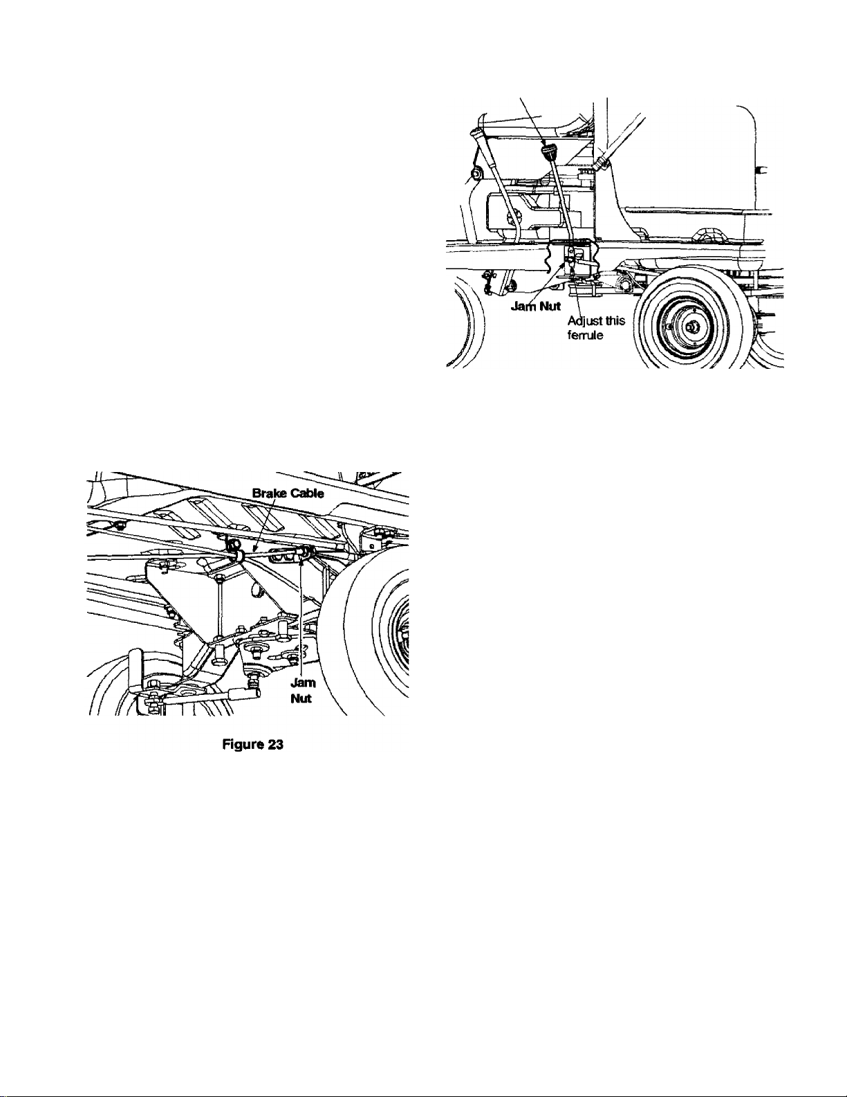
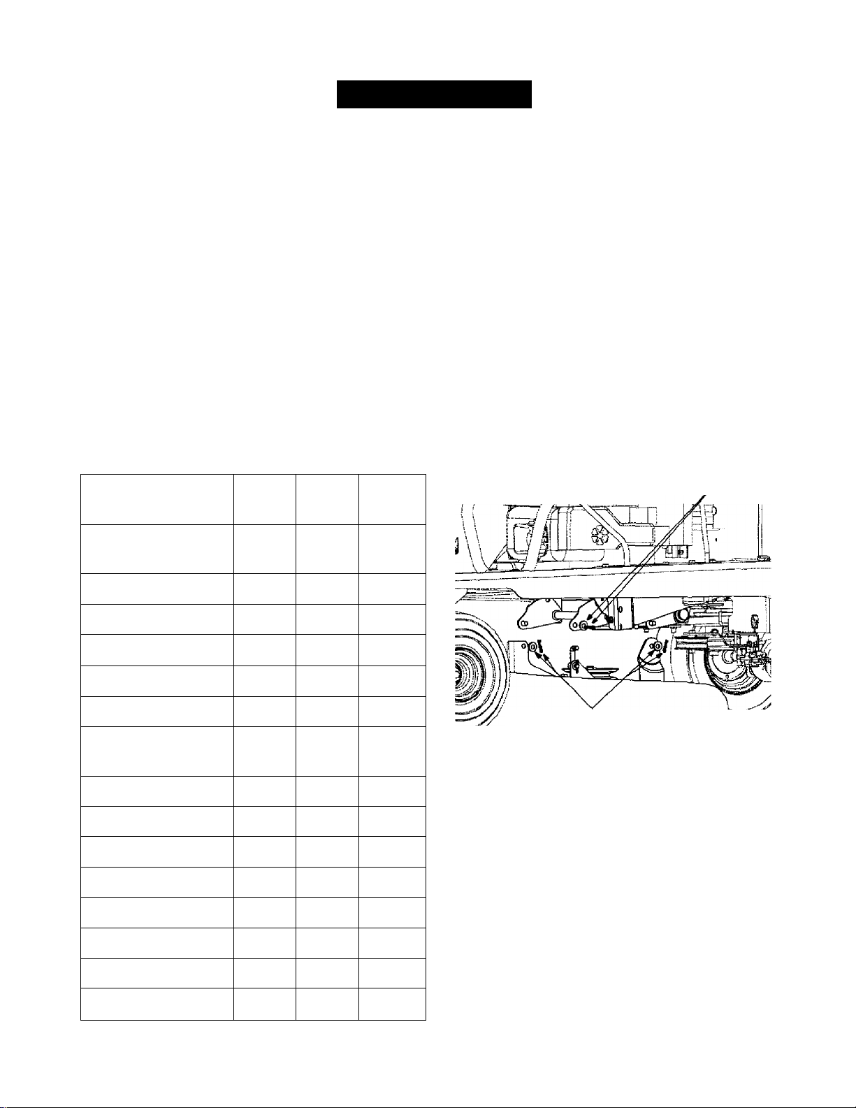
Adjusting Brake
WARNING: Do not adjust the brake while
A
NOTE: Adjustments are done at the cable end; for
adjustment of the calipers, see a Sears service center.
IMPORTANT: The brake cable should be adjusted so
that it has a bit of slack when the brake is released.
The front cable bracket is mounted on the frame behind
the pedal assembly. Both ends of the brake cable are
threaded; the longer threaded area at the pedal end
offers a wider range of adjustments.
1. Using a pair of 1 /2” wrenches, loosen the jam nuts
2. Retighten the jam nuts when proper tension is
3. Unlock the parking brake and check adjustment.
engine is running. Be sure to block the wheels
of the vehicle before attempting any
adjustment on the brake cable.
and back the cable out to tighten or thread inward
to loosen. See Figure 23.
reached. See Figure 23.
Re-adjust if necessary.
Shift Lever
Figure 24 ~ ' ’
Repiacing Fuse
The fuse is located behind the engine on the seat
support bracket. Fuses seldom fail without a reason. If
the fuse blows, the source problem must be corrected
or the new fuse will blow again.
1. Check for loose connections in the fuse holder and
replace holder if necessary. A dead short may be in
the cranking or charging circuit where insulation
may have rubbed through and exposed bare wire.
2. Replace the wire or repair with electricai tape if the
wire strands have not been damaged. Also look for
a wire pinched, burned, or rubbed against any part.
3. Stop the vehicle and engage the parking brake.
Remove ignition key.
4. Pivot the seat up. Disconnect the spark plug wire
and ground it.
5. Pull the fuse out of the fuse holder.
6. Replace with new automotive style 20 amp fuse.
7. Reconnect spark plug wire and pivot seat down.
Adjusting Shift Linkage
1.
Inspect the shift linkage for damage or wear.
2.
Disengage the parking break and push the vehicle
back and forth to verify that it is in neutral.
3.
Remove hairpin clip and washer securing fernjle to
the shift rod. See Figure 24 . Loosen the jam nut.
4.
Rotate ferrule towards the start of the threads to
adjust forward engagement.
5.
Rotate ferrule towards end of the threads to adjust
reverse engagement.
6.
Once the engagement is adjusted, tighten the jam
nut. Insert ferrule into shift rod and secure with
washer and hairpin clip, removed in step 3.
7.
Move shift rod to (N) and check for correct
adjustment.
Changing Belt
WARNING: Be sure to shut the engine off,
A
NOTE: Proper removal of the belt requires the removal
of several other components by means of special tools.
Read through the following procedure and determine if
you can successfully complete it prior to attempting;
otherwise contact a Sears service center.
IMPORTANT: The V-belts, used on this vehicle, are
specially designed to engage and disengage safely. A
substitute (non-OEM) V-belt can be dangerous by not
20
remove ignition key, disconnect the spark plug
wire and ground against the engine to prevent
unintended starting before removing belt(s).
Page 21

disengaging completely. Fora proper working machine,
use belts available from Sears.
1. Follow Rgure 25 for routing of belts and pulleys.
2. Periodically check to see if these belts are too loose
or damaged through wear and tear. If so, replace
with new belt.
NOTE: It is recommended that both drive beits be
replaced at the same time.
Special tools required: Vise grips or impact wrench.
8. Replace with new belt making sure that the
hardware is properly secured and the belts are on
the inside of the belt keepers.
Jack Spindle Replacement
Check jack spindle whenever you replace upper deck
drive belts. If the jack spindle does not spin freely when
the belts are disengaged, it should be replaced.
1. Disconnect and ground the spark plug wire.
Unhook both straps securing grass catcher to tine
2.
vehicle frame. Remove grass catcher from unit and
keep it aside.
Flip the utility bed up to access the jack spindle.
3.
Loosen the jack spindle pulley bolt using a pair of
4.
wrenches. See Figure 26.
Remove the pulley from the jack spindle.
5.
Remove four screws (only two called out in Figure
6.
26) that secure jack spindle to the vehicle frame.
Remove the jack spindle.
Variable Speed Pulley
Rgure 25
Upper Deck Drive Belt
1. Engage the parking brake and turn the ignition off.
2. Remove the cutting deck as instructed in the
previous section.
3. Disconnect spindie brake bar at the idler pulley.
Note the hardware positions for future use.
4. Remove the lower deck belt tension pulley arm. Do
not remove the spring. Note hardware position.
5. Using a 9/16” socket, remove the bolt holding the
engine pulley, and drop the pulley down. To loosen
friis bolt, you will have to hold the engine shaft
firmly with vise grips at a point closest to the bottom
of the vehicle frame. This will stop the shaft from
rotating, and help in removing the engine pulley.
6. Roll the belt off the engine pulley.
7. Slip the belt off from the idler pulley. Remove the
belt from the jack pulley.
Figure 26
8. Replace with a new jack spindle and re-attach to
the frame.
9. Working under the vehicle, re-install the jack
spindle pulley with the bolt removed earlier.
10. Flip the utility bed back to the operating position, re
attach grass catcher as needed, and re-connect the
spark plug wire.
Drive Belt
IMPORTM^: When either or both of the drive belts are
worn off, replace both. Replacing only one will affect the
performance of your lawn utility vehicle.
NOTE: It may be necessary to adjust the speed control
linkage after replacing both drive belts.
1. Remove the cutting deck.
21
Page 22

2. Remove the upper drive belt first by working from
the back of the unit. Roll the belt off the idler pulley
first and then off the transmission pulley. Next roll it
off the variable speed pulley.
3. Working from the side of the unit, pull the lower
drive belt tension pulley to the right and roll the
lower drive belt off this pulley.
4. Using a 9/16 socket, remove the bolt holding the
engine pulley, and drop the pulley down. To loosen
this bolt, you will have to hold the engine shaft
firmly with vise grips at a point closest to the bottom
* of the vehicle frame. This will stop the shaft from
rotating, and will facilitate in removing the engine
pulley.
5. Remove the belt from the two idler pulleys.
6. Remove the belt from the variable speed pulley and
the transmission pulley.
7. Replace upper deck drive belts following earlier
instructions.
8. Replace the drive belt. When re-installing the belt,
make sure belts are on the Inside of the three belt
keepers. See Figure 27.
NOTE: While re-attaching ihe lower deck belt tension
pulley arm, make sure the spring does not fall off. To
check that the spring is attached correctly, pivot the
utility bed up and you should see one end of the spring
hooked to the larger of the two holes on the bed.
Ben Keeper
Belt Keeper
Figure 27
22
Page 23

OFF-SEASON STORAGE
If the lawn utility vehicle is to be inoperative for a period
longer than 30 days, follow the steps below for storage.
Preparing for Storage
Battery
1. Fully charge the battery with a 6 amp battery
charger. NEVER store battery without a full charge.
NOTE: If a charger with 6 amp output is not availabie, a
io wer output charger may be used for a longer period of
time. Do not charge the battery at a rate higher than 6
amps as it can damage the battery and reduce its life.
2. When storing unit for extended periods, disconnect
battery cables and remove the battery from the unit.
3. Keep the terminals and the top of the battery clean
and free from corrosion. Clean the battery with
baking soda or a commercial battery cleaner.
IMPORTANT: Do not allow any cleaning solution to get
inside the battery.
Engine
1. To prevent gum from forming in fuel system or on
carburetor parts during storage, follow the
appropriate step from those listed below:
a. If fuel tank contains oxygenated or
reformulated gasoline (gasoline blended with
alcohol or ether), run engine until the gas
tank is dry.
b. If fuel tank contains gasoline only, run engine
until the gas tank is dry.
c. If a gasoline additive is being added to the
gas, run engine for several minutes, after
adding, to circulate the additive through the
carburetor. Refer to page 11 for details on
additives.
2. While the engine is still warm, change oil. Refer to
instructions on page 15.
3. Remove spark plug and pour about 0.5oz. or 15ml.
of engine oil into cylinder. Replace spark plug and
crank engine slowly to distribute the oil.
4. Remove any debris or grass clippings from the
surface of the engine.
Equipment
1. Clean entire unit thoroughly.
2. Lubricate all pivot points. Wipe the entire machine
with an oiled rag to protect the surfaces.
Storing the Equipment
1. Store unit in a clean, dry area. Do not store next to
corrosive materials, such as fertilizer.
2. When storing any type of power equipment in an
unventilated or metal storage shed, rustproof the
equipment. Using a light oil or silicone, coat the
equipment, especially any chains, springs,
bearings and cables.
After Storage
The battery loses some of its charge each day when the
unit is not used. Recharge battery before returning to
service or every two months, whichever occurs first.
NOTE: If a charger is not available but the battery will
start the lawn utility vehicle, the battery will be charged
by mowing fora minimum of one hour.
23
Page 24

TROUBLESHOOTING
Trouble
Engine fails to start
Engine runs erratic
Engine overheats
Engine hesitates at
high RPM
Idles poorly
Excessive vibration
Possible Cause
Blade control lever engaged.
1.
Parking brake not engaged.
2.
Spark plug wire{s) disconnected.
3.
Choke not activated
4.
Fuel tank empty, or stale fuel.
5.
Blocked fuel line.
6.
Faulty spark plug.
7.
Unit running with CHOKE applied.
1.
Spark plug wire loose.
2.
Blocked fuel line or stale fuel.
3.
Vent in gas cap plugged.
4.
Water or dirt in fuel system.
5.
Engine oil level low.
1.
Airflow restricted.
2.
Spark plug gap too close.
1.
Spark plug fouled, faulty or gap too wide.
1.
Cutting blade loose or unbalanced.
1.
Damaged or bent cutting blade.
2.
Remedial Action
Disengage blade control lever
1.
Engage parking brake.
2.
Connect wire(s) to spark plug.
3.
Pull out the CHOKE control
4.
Fill tank with clean, fresh gasoline.
5.
Clean fuel line or replace fuel fitter
6.
Clean, adjust gap or replace sparkplug.
7.
Push CHOKE control in.
1.
Connect and tighten spark plug wire.
2.
Clean fuel line; fill tank with fresh gasoline.
3.
Clear vent or replace cap if damaged.
4.
Drain fuel tank. Refill with fresh gasoline.
5.
Fill crankcase with correct oil.
1.
Clean grass clippings and debris from
2.
around the engine's cooling fins and
blower housing.
Remove spark plug and reset the gap
1 .
to.030”.
Replace spark plug. Set plug gap to.030”.
1.
Tighten blade and spindle. Balance blade.
1.
Replace blade.
2.
Mower will not mulch
grass
Uneven cut
NOTE: Suggestions listed here are only for minor repairs. If the problem is not resolved, or for any
problems not mentioned here, please contact Sears service by calling 1-800-4-MY-HOME®.
Wet grass.
1 .
Excessively high grass.
2.
Dull blade.
3.
Deck not balanced properly.
1.
Dull blade.
2.
Uneven tire pressure.
3.
Walt until grass is dry to cut.
1.
Mow once at a high cutting height, then
2.
mow again at desired height or make a
narrower cutting swath.
Sharpen or replace blade.
3.
Level the deck side to side.
1.
Sharpen or replace blade.
2.
Check tire pressure in all four tires.
3.
24
Page 25

PARTS LIST
Parts List for Craftsman Lawn Utility Vehicle Model 247.270250
1
For
reference
only
NOTE: For painted
parts, please refer
to the list of color
codes below. Please
add the applicable
color code, wher
ever needed, to the
part number to order
a replacement part.
For instance, if a
part, numbered 700-
xxxx, is painted polo
green, the part num
ber to order would
be 700-XXXX-0689.
Polo Green: 0689
Powder Black: 0637
Oyster Gray: 0662
' For daiity of viewing, these parts have been referred to more than once in this Illustration.
25
Page 26

Parts List for Craftsman Lawn Utility Vehicle Model 247.270250
Key No.
' Not shown in illustration
Part No.
731-1687
1.
731-1459A Steering Wheel Cap
2.
647-0055 Shift Pivot Assembly
3.
683-0432 Drive Pedal Assembly
4.
683-0433
5.
683-0592 Idler Brake Assembly
6.
710-0191 Hex Bolt 3/8-24x1.25”
7.
710-0599 TT Screw 1/4-20x0.5”
8.
710-0604A TT Screw 5/16-18 X 0.625”
9.
710-0859
10.
710-1017
11.
710-1681
12.
710-3013 Hex Bolt 1/4-20x0.50”
13.
711-0242
14.
711-0396
15.
711-1155
16.
711-1531 Shaft
17.
712-0296 Jam Nut 3/8-24
18.
712-0380 Flange Lock Nut 1/4-28
19.
712-0431
20.
712-0692 Nylon Lock Nut
21.
712-0714 Flange Lock Nut 5/16-18
22.
712-3007 Jam Nut 5/16-18
23.
712-3017
24.
714-0104
25.
714-0145 Click Pin
26.
714-0149B Hairpin Clip
27.
714-0470 Cotter Pin
28.
720-0232 Shift Knob
29.
720-0269
30.
726-0272 Clamp
31.
732-0445 Extension Spring
32.
732-0594A Extension Spring
33.
732-1167
34.
732-3091
35.
735-0283 Drive Pad
36.
735-3049 Brake Pad
37.
736-0148
38.
736-0160
39.
736-0169 Lock Washer 3/8
40.
736-0187
41.
736-0267
42.
736-0270
43.
736-0314
44.
736-0701
45.
736-0734
46.
738-0183
47.
738-0347
48.
738-0826
49.
741-0495 Flange Bearing
50.
51.
746-1089
746-1127
52.
Description
Steering Wheel
Brake Pedal Assembly
Hex Bolt 3/8-16x2,5”
AB Screw 1/4-14x0.625"
Hex Bolt
Spacer
Spacer
Ferrule
Flange Lock Nut 3/8-16
Hex Nut 3/8-16
Cotter Pin
Clutch Grip
Compression Spring
Compression Spring
Lock Washer
Flat Washer.53 x .93 x .050
Flat Washer
Flat Washer
Bell Washer
Thrust Washer
Flat Washer
Flat Washer
Shoulder Screw .50 x .21:3/8-16
Shoulder Spacer
Shoulder Screw 1/4-28 x .375
Choke Control
Deck Cable
Key No. Part No.
746-1129 Brake Cable
53.
747-1228A Shift Rod
54.
747-1240 Variable Control Rod
55.
747-1249 Control Rod
56.
747-1254
57.
747-1255
58.
747-04024
59.
747-1262 Belt Keeper Rod
60.
783-1142 Shift Switch Bracket
61.
783-1253 Shift Index Bracket
62.
783-1287 Brake Mounting Bracket
63.
783-1293 Cont. Bracket: PTO
64.
783-1307
65.
650-0007 Steering Tube Assembly
66.
683-0033A
67.
683-0178A Front Axle RH
68.
683-0179A Front A)de LH
69.
710-0459A Hex Bolt 3/8-24 X 1.5”
70.
710-0643
71.
710-0689
72.
710-0837 AB Screw #10-16 x 0.625”
73.
710-0958 Hex Bolt 1/4-20x1.25"
74.
712-0116
76.
712-0206 Hex Nut 1/2-13
77.
712-0241 Hex Nut 3/8-24
78.
712-0324 Hex Lock Nut 1/4-20
79.
712-0411
80.
712-0692 Hex Lock Nut
81.
723-0156 Ball Joint 3/8-24
84.
731-0559B Steering Bellow
85.
736-0105 Bell Washer
86.
736-0196
89.
736-0242
90.
736-0272
91.
736-0320 Flat Washer 3/8 x 1.37
92.
736-3078 Flat Washer .344 x 1.0 x .063
93.
738-0541 Spacer
94.
738-3089A Steering Adapter
95.
741-0225 Hex Flange Bearing
96.
741-0356 Bearing: Steering Column
97.
747-0955 Tie Rod
98.
748-0290
99.
750-0532 Spacer
100.
783-1302
101.
Description
Shift Rod
PTO Lever
Brake Lock -Out Rod
Link Bracket
Steering Support Bracket Assembly
Hex Bolt 5/16-18 X 1.0"
Hex Bolt 1/2-13x0.75”
Jam Lock Nut 3/8-24
Hex Lock Nut 5/16-24
Flat Washer.628 x 1.56 x .036
Bell Washer .340 x .872 x .060
Flat Washer .510 x 1.0 x .060
Pinion Gear
Steering Gear
102. 783-1129 Cover: Steering Column
103.
634-0169A
634-0170A
Complete Wheel /\ssembly; Front
Rim Assembly*
734-0255 Valve*
741-0487A FI. Bearing*
741-0706 FI. Bearing*
104.
714-0115
Cotter Pin
26
Page 27

Parts List for Craftsman Lawn Utility Vehicle Model 247.270250
IMPORTANT: For a proper working
machine, use Factory Approved Parts.
V-BELTS are specially designed to engage
and disengage safely. A substitute (non
OEM) V-Belt can be dangerous by not
disengaging compieteiy.
NOTE: For painted parts, please refer to
the list of color codes below. Please add the
applicable color code, wherever needed, to
the part number to order a replacement
part. For instance, if a part, numbered 700xxxx, is painted polo green, the part number
to order would be 700-xxxx-0689.
Polo Green: 0689
Powder Black: 0637
Oyster Gray: 0662
27
Page 28

Parts List for Craftsman Lawn Utility Vehicle Model 247.270250
Key No.
1.
2.
3.
4.
5.
6.
7.
8.
9.
10.
11.
12.
13.
14.
15.
16.
17.
18.
19.
20.
21.
22.
23.
24.
Part No. Description
618-04007
619-0011
683-0446
683-0447
710-0191
710-0459A
710-0521
710-0539
710-0650
Transmission Assembly*
Spindle Housing
Idler Bracket Assembly
Idler Bracket Assembly
Hex Bolt 3/8-24x1.25”
Hex Bolt 3/8-24 X 1.50”
Hex Bolt 3/8-16x3.0”
Hex Bolt3/8-24x 1.75’
TT Screw 5/16-18 X 0.875"
710-0902 Hex Screw 3/8-24 x 3.75”
710-1039 Hex Screw 3/8-24 x 1.0”
710-1812
Hex Screw M20 x 2.5:180
712-0241 Hex Nut 3/8-24
712-0296
Jam Lock Nut 3/8-24
712-0695 Hex Flange Nut M20 x 2.5
712-3004A
Flange Lock Nut 5/16-18
712-3017 Hex Nut 3/8-16
712-3035 Jam Nut 9/16-18
714-0133 Key
717-0884 Variable Speed Pulley Assembly
732-0308 Extension Spring
732-0418 Extension Spring
732-0814
Extension Spring
736-0101 Flat Washer .406 x 1.0 x .030
Key No. Part No.
736-0169
25.
736-0219
26.
736-0247 FlatWasher3/8x 1.25”
27.
736-0427 Bell Washer .567 x 1.125 x .06
28.
736-3052 Flat Washer .406 x 1.0 x .105
29.
738-0155
30.
738-0347
31.
738-0968
32.
741-0405
33.
741-0919
34.
750-0705
35.
750-0952
36.
754-0453
37.
754-0493 Belt: V Type
38.
754-0494
39.
756-0650 Transmission Pulley
40.
756-0981A Flat Idler Pulley
41.
756-1195
42.
756-1200
43.
756-1207 Idler Pulley
44.
783-0528
45.
783-1292 Cable Bracket
46.
783-1341 Bracket: Lock: Pedal
47.
Description
Lock Washer 3/8
Bell Washer .39 x 1.13 x .062
Shoulder Screw
Shoulder Spacer
Shoulder Spacer
Thrust Bearing
Ball Bearing
Sleeve Spacer
Spacer
Belt: V Type
Belt: V Type
Jack Pulley: Double
Engine Pulley: Double
Idler Bracket: Variable Speed
' For full break-down of the transmission assembly, see page 34.
Key No. Part No.
Description
634-0212 Rear Wheel Assembly Complete: 13x5x6
1.
634-0211 Rim Assembly
734-0255
734-0298
736-0242
2.
710-0627 Hex Bolt 5/16-24 X.750
3.
Valve
Flange Bearing
Bell Washer .340 x .872 x .060
28
Page 29

Parts List for Craftsman Lawn Utility Vehicie Model 247.270250
NOTE: For painted
parts, please refer to
the list of color codes
below. Please add
the applicable color
code, wherever
needed, to the part
number to order a
replacement part. For
instance, if a part,
numbered 700-xxxx,
is painted polo green,
the part number to
order would be 700-
xxxx-0689.
Polo Green; 0689
Powder Black: 0637
Oyster Gray: 0662
For refererx» onl'
i I 32
29
Page 30

Parts List for Craftsman Lawn Utility Vehicle Model 247.270250
Key No.
1.
2.
3.
4.
5.
6.
7.
8.
9.
10.
11.
12.
13.
14.
15.
16.
17.
18.
19.
20.
21.
22.
23.
24.
25.
26.
27.
28.
29.
30.
31.
32.
33.
34.
35.
36.
37.
' If equipped
Part No.
757-04000
683-0575
683-0576
710-0604A
710-1250
710-1681
710-1690
710-1703
712-0431
712-0689
712-0692
712-3004A
726-3046
732-0735
732-0750A
732-0996
732-0997
736-0105
736-0289
736-0648
736-0743
738-1014
Description
Seat
Support Bracket Assembly LH 39.
Support Bracket Assembly RH
TT Screw 5/16-18 X 0.625” 42.
Carriage Bolt 5/16 x 1.5” 43.
HexBoltM8-1.25;20
Special Screw M6-1:16 45.
Hex Bolt M8-1.25:45 46.
Flange Lock Nut 3/8-16
Hex Nut M6-1 48.
Hex Lock Nut M8-1.25 49.
Flange Lock Nut 5/16-18
Ratchet Clip 51.
Compression Spring
Actuator Spring
Compression Spring
Compression Spring
Bell Washer .375 x .870 x .063
Shoulder Bushing 58.
Lock Washer
Flat Washer 8.4 x 35
Shoulder Screw
Key No.
38.
40.
44.
47.
50.
52.
53.
55.
56.
57.
59.
60.
61.
749-1264 Support T ube: Seat 62.
783-04005
783-0733
783-0931
783-1118A
17962
683-0142
683-0581
683-0591
683-0593
710-0224
710-0599
Seat Bracket
Spacer 64.
Bag Switch Bracket
Seat Support Bracket
Switch Plate 67.
Pivot Bar Assembly
Support Bracket Assembly RH
Bracket Assembly: Steering Column
Pivot Support Bracket: Front
Ab Screw #10-16 X 0.5"
TT Screw 1/4-20x0.5”
710-0946 Machine Screw * 74.
710-1681
Hex Screw M8-1.25:20
710-1708 Special Screw
63.
65.
66.
68.
69.
70.
71.
72.
73.
75.
76.
Part No.
710-1752
711-1165
712-0185
712-0640
712-0692
712-0714
714-0470
723-0491
723-0604
728-0285
731-04013
731-2360
736-0187
736-0700
736-0765
750-1293
783-04004
783-1081A
783-1097
783-1101
783-1148
783-1260
783-1292
710-0654A
783-1294
710-1683
711-1065
712-0692
712-3010
722-0153
736-0119
736-0701
747-1292
750-0539
783-1120
725-1698
710-0870
Description
Special Screw
Clevis Pin
Speed Nut 1/4-20 *
Hex Nut
Hex Lock Nut
Flange Lock Nut
Cotter Pin
Tray
Foot Pad
Rivet
Battery Cover*
Bag Tray
Flat Washer .64 x 1.24 x ,06
Flat Washer 8.4x16
Lock Washer M4
Spacer
Bracket: Battery Support
Frame
Rear Bracket: Pivot Support
Support Bracket: Transmission
Chute Bracket
Stop Bracket: Pivot
Cable Bracket
TT Sems Screw 3/8-16 x 1.0
Beit Keeper Bracket
HexBoltM8-1.25:30
Pin: Belt Guard
LockNutM8-1.25
Hex Nut 5/16-18
Engine Mount: Gromm.
Lock Washer 5/16
Flat Washer 8.4 x 24
Belt Keeper Rod
Spacer
Mounting Plate
Battery*
Self-Tapping Screw
30
Page 31

Parts List for Craftsman Lawn Utility Vehicle Model 247.270250
NOTE: For painted parts, please refer to the list of color codes below. Please add the applicable color
code, wherever needed, to the part number to order a replacement part. For instance, if a part, num
bered 700-xxxx, Is painted polo green, the part number to order would be 700-xxxx-0689.
Polo Green: 0689
Powder Black; 0637
Oyster Gray; 0662
31
Page 32

Parts List for Craftsman Lawn Utility Vehicle Model 247.270250
Key No.
Part No.
683-0441 Shift Assembly: Front Lift
1.
683-0442
2,
683-0448
3.
710-0641
4.
710-1681
5.
711-0832 Ferrule
6.
712-0431 Flange Lock Nut 3/8-16
7.
712-0692
8.
712-3027
9.
714-0104 Hairpin Clip
10.
716-0106 E-Ring
11.
731-2509
12.
732-1020
13.
736-0314
14.
736-0336
15.
736-0341B
16.
736-3010
17.
738-0281 Shoulder Screw .625 x. 17:3/8-16
18.
747-1247
19.
750-0566A Spacer
20.
21. 783-1136
22. 783-1138
783-1143
23.
24. 619-0020
Description
Pivot Bracket Assembly
Bracket Assembly: Lift Handle
Hex Bolt 1/4-20x2.25
HexBoltM8-1.25:20
Hex Lock Nut M8-1.25
Lock Nut 1/4-20
Handle Grip
Torsion Spring
Thrust Washer .375 x .70 x .030
Flat Washer 5/8 x 1.0 x .030
Flange Washer .633 x .883
Flat Washer .407 x .812 x .135
Lift Link
Upper Lift Link Bracket
Lift Hanger Bracket
Lift Indx. Bracket
Spindle Housing
Key No. Part No.
783-1082
25.
710-0347 Hex Screw 3/8-16x1.75
26.
710-0514 Hex Bolt 3/8-16 X 1.0
27.
710-0650
28,
712-0417A Flange Nut 5/8-18
30.
712-3017
31.
726-0365 Speed Nut
32.
731-2361A Grass Catcher Chute
33.
731-2477 Side-Discharge Chute
34.
731-2505
35.
732-0814
36.
736-0169
37.
736-0701
38.
738-0933 Spindle Shaft
39.
738-0968
40.
741-0919
41.
742-0667 Blade: Bagging
42.
742-0760 Blade: 3-in-1
43.
750-1000
44.
754-0495
45.
756-0969 Deck Pulley
46.
756-0981A Flat Idler Pulley
47.
783-1122 Idler Bracket: Deck
48.
Description
Deck
TT Screw 5/16-18 x 0.875
Hex Nut 3/8-16
Mulch Plug
Extension Spring
Lock Washer
Flat Washer 8.4 x 24
Shoulder Spacer
Ball Bearing
Spacer
Belt: V Type
32
Page 33

Craftsman Lawn Utility Vehicle Model 247.27Q250
Key No,
NOTE: For painted parts, please refer to the list of color codes below. Please the applicable color code,
wherever needed, to the part number to order a replacement part. For instance, if a part, numbered 700xxxx, is painted polo green, the part number to order would be 700-xxxx-0689.
Part No.
649-0126 Tube Assembly: Front Frame
1.
664-0107
2.
710-1194 Mach. Screw #10-24x1.0
3.
712-0161 Lock Nut #10-24
4.
723-0383 Retainer Strap
5.
736-0400
6.
749-1260
7.
749-1262 Bag Handle
8.
749-1269 Support Tube
9.
Description
Grass Catcher Bag
Flat Washer
Side Tube: Frame
Polo Green: 0689
Powder Black: 0637
Oyster Gray: 0662
33
Page 34

Parts List for Craftsman Lawn Utility Vehicle Model 247.270250
|o
w
li i
1 \
&
1
1 ■
xy
--------N ^
7
Key No.
1.
2.
3.
4.
5.
6.
7.
8.
9.
10.
11.
12.
13.
Part No. Description
611-0011
618-0072B Upper Housing Assembly
618-0135 Drive Shaft Assembly: LH Brake
618-04009 Axle Assembly
661-0043
710-1325 TT Screw 1/4-20x1.625”
717-0678 Break Pad
719-0313B Lower Housing
732-0863 Spring Detent
737-0148 Grease
741-0862 Ball: Detent: .250
761-0202
618-04007 Transmission Assembly Complete:
Shaft Assembly: Detent
Brake Assembly: Yoke LH
Brake Disc
Single Speed
34
Page 35

ENGINE
MODULE
Page 36

-0
Vi
0>
■4i
o
0
1
3
fi)
3
f
3
<
<D
o"
5*
3
o
a
®
ro
il
io
>J
0
ro
01
o
KEY
SWITCH
Page 37

Parts List for Craftsman Lawn Utility Vehicle Model 247.270250
Safety & Decorative Labels
777D06242
ON STEERING CAP
777122019
777I20889
(MODEL PLATE
ON RIGHT SIDE)
777I20890
777D06238
Some of №ese symbols will be found
on the engine or in №e manual or
labels on the lawn utility vehicle. Interpret
them as indicated here, and follow
the message.
M
Fire
Explosion
777I22020 777D06240
777D06241
A
Safety Alert
Moving Parts
Stop
CRRFTSMRN
0
Fuel
Oil
777530018,
I o
On Off
M
Choke
Toxic Fumes
Shock
Hot Surface
36
Kickback
Read Owner's
Manual
H!
Fuel Shutoff
Primer
Page 38

Parts List for Briggs & Stratton Engine 12607-O324 for Lawn Utility Vehicle Model 247.270250
37
Page 39

Parts List for Briggs & Stratton Engine 12607-0324 for Lawn Utility Vehicle Model 247.270250
365 <
38
Page 40

Parts List for Briggs & Stratton Engine 12607-0324 for Lawn Utility Vehicle Model 247.270250
333
334 f
I 1036 LABEL-EMISSION
e
851
1005
363
39
Page 41

Parts List for Briggs & Stratton Engine 12607-0324 for Lawn Utility Vehicle Model 247.270250
Key No.
Part No.
1
697639 Cylinder Assembly
2
399269 Kit: Bushing Seal 121
3
299819 Oil Seal (Magneto Side)
4
499619 Sump; Engine
5
695276
7
697230
8
495786 Breather Assembly
9
272481 Gasket: Breather
Description
Head: Cylinder
Gasket: Cylinder Head
10 691125 Screw (Breather Assembly)
11
691260
12 692232
Tube: Breather
Gasket: Crankcase
13 691137 Screw (Cylinder Head)
15
691680 Plug: Oil Drain
16 691457
Crankshaft
20 399781 Oil Seal (PtoSide)
22 691092 Screw (Engine Sump)
23 697637
24
222698
25 499627
692788
Flywheel
Flywheel Key 227 691467
Piston Assembly (Standard)
Piston Assembly (.010” Oversized)
692789 Piston Assembly (.020” Oversized)
692790
26 499631
692785
692786
692787
27
691866
28
499423 Piston Pin (Standard)
29 499424
32 691664
32A
695759 Screw; Connecting Rod
33 499642
34
499641
35 691304
36 691304
40 692194
43 691997
45 690977
46 694039
51
692668
51A 692799
73 691221
95
691636
97
499681 Shaft: Throttle
104 691242
108 691182
109
499681
117
498978
Piston Assembly (.030” Oversized)
Ring Set (Standard)
Ring Set (.010" Oversized)
Ring Set (.020” Oversized)
Ring Set (.030” Oversized)
Piston Pin Lock
Connecting Rod
Screw: Connecting Rod
Exhaust Valve
Intake Valve
Spring; Intake Valve
Spring: Exhaust Valve
Retainer; Valve
Slinger—Govemor/oil
Tappet: Valve
Camshaft
Gasket: Intake
Gasket: Intake
Screen: Rotating
Screw: Throttle Valve
Pin: Float Hinge
Valve: Choke
Shaft; Choke
Jet-Main (Standard)
Key No.
118
Part No.
498975 Jet-Main (High Altitude)
Description
692703 Kit: Carburetor Overhaul
694203 Carburetor
125
127 694468
130 691203
Plug: Welch
Valve: Throttle
133 398187 Float: Carburetor
134 398188
Kit: Needle/seat
137 693981 Gasket: Float Bowl
146 690979 Key: Timing
163 691894 Gasket: Air Cleaner
187 691050 Fuel Line
691147 Screw (Control Bracket)
188
190 690940 Screw (Fuel Tank)
192 694543 Ball: Rocker Arm
202
691303 Link: Mechanincal Governor
209
691290
222 692723
Spring: Governor
Control Bracket
Lever: Governor Control
238 691300 Cap: Valve
259
691189 Bracket: Casing damp
276 271716
287
690940
Washer: Sealing
Screw (Dipstik Tube)
300 694248 Muffler
304
499676
Blower Housing
305 691108 Screw (Blower Housing)
306 691232
307 690345
Shield: Cylinder
Screw: Cylinder Shield
309 695550 Starter Motor
310 692327
332 690662
333 802574
334
691061
337
692051
Bolt (Starter Motor)
Nut (Flywheel)
Armature: Magneto
Screw: Magneto Armature)
Spark Plug
356 692151 Stop Wire
358 694090
363
19069
365
691136 Screw (Carburetor)
383 19374
404
690272
443 690255
445 697029
455
695161
474
695730 Alternator
505 231082
510 494147
Gasket Set: Engine
Flywheel Puller
Spark Plug Wrench
Washer (Governor Crank)
Screw (Air Cleaner Primer Base)
Filter: Air Cleaner Cartridge
Flywheel Cup
Nut (Governor Control Lever)
Drive; Starter
513 692358 Drive Clutch
523 499621
524
692296
Dipstick
Seal: 0-Ring
40
Page 42

Parts List for Briggs & Stratton Engine 12607-0324 for Lawn Utility Vehicle Model 247.270250
Key No.
525 495265
Part No.
Description Key No.
Dipstick Tube
529 692937 Grommet
690244
534
690786 Armature: Starter
544
492919
545
94852
562
584 692342
691879 Gasket: Breather Passage 883
585
95162 Hose Clamp
601
691140
613
613A 691108
690340
615
691308
616
619 691108
691321
633
633A
693867 Seal: Chokefthrottle Shaft 967
66538 Spark Plug Boot 968
635
Screw {Air Cleaner Cover) 836A
Washer Set
Bolt (Governor Control Lever)
Cover: Breather Passage
Screw (Exhaust Muffler)
Screw (Exhaust Muffler)
Retainer: Governor Shaft
Crank: Governor 937 691325
Screw (Cylinder Head Plate)
Seal: Choke/lhrottle Shaft
651 690345 Screw (Starter Gear Cover) 972
692294
670
684
690345
690572 Spring: Detent
692
697 691127
690959
718
741 691830
93941
742
783 691918
783A
784
691269
692341
785 692352
801 690782
Spacer (Fuel Tank)
Screw (Breather Passage Cover)
Screw (Drive Cap)
Pin: Locating
Gear: Timing
Retainer: E-Ring 1022 691890
Gear: Pinion 19T
Gear: Pinion 12T
Cover: Starter Gear 1029 691230
Gasket: Starter Cover 1034
Cap: Drive
802 695267 End Cap
803 695266
830 694544
Starter Housing
Stud (Rocker Arm)
Part No.
832 691466
836 607551
691147
842 691031
692047 Dipstick Tube Assembly
847
851 493880
Description
Muffler Guard
Screw (Muffler Guard)
Screw (Muffler Guard)
Seal: O-ring
Spark Plug Terminal
868 692044 Valve Seal
691893 Exhaust Gasket
886 696268
914 691108
Gasket Kit: Cylinder Head/Plate
Screw (Rocker Cover)
930 691919 Guard: Rewind
930A
499679
Guard: Rewind
Spline: Starter
957 692046 Fuel Tank Cap
966
690243
Base: Air Cleaner Primer
273356 Filter: Pre-Cleaner
692435
Air Cleaner Cover
499618 Fuel Tank
493640 Float Bowl
975
694395
976
692704
977
993 694088
1005
691346
Primer
Gasket Set: Carburetor
Gasket: Cylinder Head Plate
Fan: Flywheel
1019 499691 Label Kit
Gasket: Rocker Cover
1023
499624
1026 692045
Rocker Cover
Push Rod
Rocker Arm
691343
Guide: Push Rod
1036 696767 Emission Label
1059
1119 691183
692311 Screw/Washer Kit
1095
694091 Set: Valve Gasket
Screw (Alternator)
41
Page 43

INDICE
......
......
......
......
......
Página
54
58
62
63
64
índice de materias
Información sobre la garantía
Prácticas de funcionamiento seguras .
Determinación de la pendiente...............
Montaje
Funcionamiento
.....................................................
.......................................
................
Página índice de materias
.....
.....
.....
.....
.....
42
43
46
47
49
Mantenimiento......................................
Servicio y ajustes.................................
Almacenamiento prolongado..............
Resolución de problemas
Información de la ayuda de cliente...
...................
INFORMACIÓN SOBRE LA GARANTIA
GARANTÍA LIMITADA SOBRE EL VEHÍCULO UTILITARIO CORTACÉSPED
Por dos (2) años a partir de la fecha de compra, si al equipo de montaje Craftsman se le da mantenimiento, lubricación y
afinación de acuerdo con las instrucciones en el manual del propietario, Sears reparará o reemplazará libre de cargo
cualquier pieza que esté defectuosa en material y mano de obra de acuerdo con la guía de cobertura que se describe más
abajo.
Sears proporcionará también sin costo en la mano de obra aquellas piezas en garantía por los dos años completos. Durante
los primeros 30 días a partir de la fecha de compra, no habrá cargos por dar servicio al producto en su domicilio para aquello
que esté cubierto en esta garantía. (Vea las excepciones más abajo).
Para su conveniencia, el servicio de garantía EN SU CASA estará disponible de^ués de los primeros 30 días de la fecha de
compra, pero se le hará un cargo por gastos de transporte. Este cargo no se realizará si el producto Craftsman se lleva hasta
un centro autorizado de Sears. Para conocer el centro autorizado Sears más cercano, por favor llame al 1-800-4-MY-
Home(r). Esta garantía tiene validez únicamente mientras el producto esté en los Estados Unidos.
EXCLUSION
Esta garantía no cubre:
• Artículos de duración limitada que sufren desgaste bajo condiciones normales de uso, incluyendo sin limitaciones las
cuchillas, bujías de encendido, purificadores de aire, correas y filtros de aceite.
• Sen/icio normal de mantenimiento, cambio de aceite o afinaciones.
• Reemplazo o reparación de neumáticos debido a pinchaduras causadas por objetos externos, tales como clavos, espinas,
tocones o vidrio.
■ Reparaciones necesarias debido al abuso del operador, incluyendo pero sin limitarse a daño causado por cargar objetos
más allá de la capacidad de carga del equipo o por objetos que hacen impacto que puedan doblar la estructura o el eje del
cigüeñal o puedan sobreacelerar el motor.
• Reparaciones necesarias debido a negligencia del operador, incluyendo pero sin limitarse a daños eléctricos y mecánicos
causados por almacenamiento incorrecto, falla en la calidad o cantidad del aceite de motor utilizado, falla para mantener la
cubierta libre de desechos inflamables, o falla para mantener el equipo de acuerdo con las instrucciones contenidas en el
manual del propietario.
• Limpieza o reparaciones del (sistema de combustible del) motor causadas por combustible que se encontró que estaba
contaminado и oxidado (vencido). Por lo general, el combustible debe utilizarse dentro de los 30 días posteriores a la fecha
de compra.
• Deterioro y desgaste normal de los acabados exteriores o reemplazo de etiquetas del producto.
• Equipos utilizados para fines comerciales o de alquiler.
GARANTÍA LIMITADA SOBRE EL ACUMULADOR ELÉCTRICO
Por noventa (90) días a partir de la fecha de compra, si cualquier acumulador eléctrico Incluido con este equipo se
demuestra como defectuoso en material o mano de obra y las pruebas que realicemos determinan que el acumulador no
retiene la carga, Sears reemplazará el acumulador sin costo. Durante los primeros 30 días a partir de la fecha de compra, no
habrá cargos por dar servicio al acumulador en su domicilio. Para su conveniencia, el servicio de garantía EN SU CASA
estará disponible después de los primeros 30 días de la fecha de compra, pero se le hará un cargo por gastos de transporte.
Este cargo no se realizará si el producto Craftsman se lleva hasta un centro autorizado de Sears. Para conocer el centro
autorizado Sears más cercano, por favor llame al 1-800-4-MY-Home(r). Esta garantía sobre el acumulador tiene vigencia
únicamente mientras el producto esté en los Estados Unidos. Esta garantía le otorga derechos legales específicos y también
usted puede tener otros derechos, los cuales varían de un estado a otro.
Sears, Roebuck and Co.,Dept.817WA, Hoffman Estafes, iL 60179
ESPECIFICACIONES DEL PRODUCTO
Caballos de fuerza:
Aceite para motor
Combustible
Bujías de encendido:......
Motor
................................
Key
...................................
........
...........
....................
.........
6.75
........
22 oz. 0 0.65 litros
.........
regular sin plomo
........
N/P 692051
........
12607-0324-E1
NUMERO DE MODELO
Número de Modelo 247.270250
Número de Serie
Fecha de compra
Guarde el número de serie y la fecha de compra en un
tugar seguro para referencia futura.
42
...................................................
.................................................
Page 44

PRÁCTICAS IMPORTANTES PARA UN FUNCIONAMIENTO SEGURO
ADVERTENCIA: La presencia de este símbolo indica que se trata de instrucciones importantes de seguridad
ák
ák
ák
que debe respetar para evitar poner en riesgo su seguridad personal y / o material y de otras personas. Lea y
siga todas las instrucciones contenidas en este manual antes de intentar poner esta máquina en funcionamiento.
De no hacerlo puede ocasionar lesiones. Cuando encuentre este símbolo • respete la advertencia que aparece a
continuación del mismo.
ADVERTENCIA: El acumulador y el escape del motor de este producto contienen productos
químicos que el estado de California considera que pueden producir cáncer, defectos de
nacimiento u otros problemas reproductivos. El acumulador y las terminales contienen plomo.
Lávese las manos después de tener contacto con ellas..
ADVERTENCIA: Esta máquina está diseñada para ser utilizada respetando las regias de seguridad contenidas
en este manual. Al igual que con todos los equipos eléctricos si el operador es descuidado o comete errores
puede ocasionar lesiones graves. Esta máquina puede amputar manos y pies y arrojar objetos. De no respetar
las instrucciones de seguridad siguientes se pueden producir lesiones graves o la muerte.
Funcionamiento general
1. Lea, comprenda y siga todas las instrucciones de la
máquina y de el o los manuales antes de intentar
montarla y operarla. Guarde este manual en un lugar
seguro para referencias futuras y periódicas y para
soíicítar repuestos.
Familiarícese con todos los controles y con el uso
2.
adecuado de los mismos. Sepa cómo detener la
máquina y cómo desengranar los controles rápidamente.
Nunca permita que niños menores de 14 años operen
3.
esta máquina. Los niños de 14 años y más deben leer y
comprender las instrucciones de operación y las reglas
de seguridad contenidas en este manual y deben ser
capacitados y supervisados por uno de los padres.
4.
Nunca permita que adultos sin conocimiento acerca de la
máquina operen la misma.
5.
Para evitar una lesión producida por el contacto con las
cuchillas o un objeto que sea arrojado, mantenga a todas
las personas, ayudantes, niños y mascotas alejados ai
menos 75 pies de la máquina mientras se encuentre
funcionando. Detenga la máquina si alguien entra en la
zona.
6.
Re\nse minuciosamente la zona donde se utilizará el
equipo. Retire todas las piedras, varas, cables, huesos,
juguetes y otros objetos extraños que puedan ser
atrapados y arrojados por la(s) cuchilla(s). Los objetos
lanzados pueden causar lesiones personales graves.
7.
Planifique su patrón de poda para evitar la descarga de
material hacia caminos, aceras, transeúntes y otras
personas. También evite la descarga de material contra
una pared u obstáculo que pudiera provocar que el
material descargado regrese hacia ei qserador.
8.
Use siempre protección ocular o gafas de seguridad
durante la operación y mientras realiza algún ajuste o
reparación. Los objetos arrojados que lo golpeen pueden
causar lesiones oculares graves.
9.
Utilice zapatos de trabajo resistentes, de suela fuerte y
pantalones y camisas ajustados. Las prendas sueltas o
las alhajas pueden quedar atrapadas en las piezas
movibles. Nunca opere esta máquina estando descalzo o
con sandalias.
10.
Esté atento a que la dirección de la descarga de la
podadera y sus accesorios no apunten hacia ninguna
persona. No haga funcionar la podadera sin la cubierta
de descarga o el recolector de pasto en su lugar,
11.
No acerque sus manos ni sus pies a las partes móviles ni
bajo la cubierta de la cortadora. El contacto con las
cuchillas puede amputar manos y pies.
12.
Una cubierta de descarga dañada o faltante puede
causar lesiones por contacto con las cuchillas o por
objetos que sean arrojados.
13.
Detenga las cuchillas cuando cruce entradas de gravina,
aceras o caminos y mientras no esté cortando el césped.
Esté atento al tránsito cuando esté operando cerca de un
14.
camino o de un cruce. Esta máquina no está diseñada
para usarse en la vía pública.
15.
No opere la máquina bajo la influencia del alcohol o las
drogas.
16.
Corte el césped solamente durante el día o con una
buena fuente de luz artificial. Nunca lleve pasajeros.
17.
Desenganche las cuchillas antes de cambiar a reversa.
Retroceda lentamente. Siempre mire abajo y atrás antes
y mientras retrocede para evitar un accidente al manejar
en reversa.
18.
Baje la velocidad para dar la vuelta. Haga funcionar la
máquina suavemente. Evite el ñjncionamíento errático y
las altas velocidades.
19.
Desenganche tas cuchillas, coloque el freno de mano,
detenga el motor y espere hasta que las cuchillas se
detengan completamente antes de retirar el colector de
pasto, vaciar el pasto, destapar la cubierta, retirar
cualquier pasto o desecho, o realizar cualquier ajuste.
20.
Nunca deje la máquina funcionando sin atención.
Siempre apague las cuchillas, coloque la transmisión en
neutral, coloque el freno de mano, detenga el motor y
retire la llave antes de bajarse.
21.
Tenga especial cuidado cuando cargue o descargue la
máquina en un camión o camioneta. Esta unidad no
debe ser manejada hacia arriba o hacia abajo de rampas
debido a que podría volcarse, causando lesiones
personales de gravedad. La unidad debe ser empujada
manualmente en tas rampas para carga o descarga
apropiadas.
22.
El silenciador y el motor se calientan y pueden producir
quemaduras. No los toque.
43
Page 45

23. Compruebe los espacios Ubres con cuidado antes de
manejar bajo las ramas de los árboles, cableado, las
aperturas de puertas, etc. cuando el operador pueda ser
golpeado o sacado de la unidad, lo que resultarfa en
lesiones personales de gravedad.
24. Desenganche todos los embragues de ios accesorios,
presione completamente el pedal de freno y cambie a
neutral antes de Intentar arrancar el motor.
25. Su máquina está diseñada para cortar césped
residencial normal de un alto rro mayor a 10". No Intentar
podar césped muy crecido, pasto seco (forraje) o pilas de
hojas secas. Ei pasto seco o las hojas pueden hacer
contacto con ei escape del motor y/o acumularse en la
cubierta de la podadera, representando un riesgo de
incendio.
26. Use solamente accesorios y acopiamientos aprobadas
para esta máquina por el fabricante. Lea, entienda y siga
todas las Instrucciones proporcionadas con el accesorio
o acoplamiento.
27. Las estadísticas indican que los operadores de 60 años
o más, se ven involucrados en un alto porcentaje de
accidentes relacionados con tractores. Estos operadores
deben evaluar su capacidad para operar el tractor en
forma lo suficientemente segura para protegerse a sí
mismos y a los demás de lesiones.
28. Si se presentan situaciones que no están previstas en
este manual sea cuidadoso y use el sentido común.
Contacte al centro de servicio Sears para obtener ayuda.
Operación en pendientes
1. Las pendientes son uno de los principales factores
relacionados con la pérdida de control y los accidentes
por volcaduras que pueden causar lesiones graves o la
muerte. Todas las pendientes requieren cuidado
adicional. Si no puede dar marcha atrás en la pendiente
o no se siente cómodo, no la pode.
2. Por razones de seguridad, utilice el calibrador de
pendiente que se incluye como parte de este manual
para medir ia pendiente antes de operar esta unidad en
un área con pendientes o colinas. Sí la pendiente es
mayor a 15 grados como se muestra en el calibrador de
peridiente, no haga funcionar esta unidad allí.
Haga lo siguiente:
1. Muévase hacia arriba y hacia abajo en ias
pendientes, no ias cruce. Tenga precaución extrema
cuando cambie de dirección en una pendiente.
2. Esté atento a agujeros, surcos, baches, piedras y
otros objetos ocultos. Un terreno irregular puede
volcar la máquina. El césped muy crecido puede
esconder obstáculos.
3. Vaya siempre a baja velocidad. Elija una velocidad lo
suficientemente baja para que no tenga que
detenerse o hacer cambios mientras está en la
pendiente. Los neumáticos pueden perder su tracción
en las pendientes aunque los frenos funcionen
adecuadamente. Siempre mantenga la máquina con
la velocidad seleccionada cuando baje las pendientes
para aprovechar la acción del frenado con motor.
4. Siga las recomendaciones del fabricante sobre los
pesos o contrapesos de las ruedas para mejorar la
estabilidad de la máquina. Tenga especial cuidado
con el recolector de pasto u otros acoplamientos.
Estos pueden hacer variar ia estabilidad de la
máquina.
44
5. Realice todo movimiento en las pendientes en forma
lenta y gradual. No cambie repentinamente la
velocidad o la dirección. Un cambio rápido o frenado
pueden causar que el frente de la máquina se levante
y se vuelque hacia atrás, ocasionando graves
lesiones.
6. Evite arrancar o detenerse en una pendiente. Si los
neumáticos pierden tracción, desenganche las
cuchillas y proceda a bajar lentamente la pendiente.
No:
1. No vire en una pendiente a menos que sea necesario.
En ese caso, vire lenta y gradualmente cuesta abajo,
si es posible.
2. No corte el césped cerca de zanjas, canales o
terraplenes. La podadera podría volcarse si una rueda
está sobre el borde de un risco, zanja o si un borde se
derrumba.
3. No intente mantener la estabilidad de la máquina
poniendo su pie en el suelo.
4. No utilice el recolector de pasto en las pendientes.
5. No corte el pasto que esté mojado. La reducción de la
tracción podría causar un derrape.
6. No cambie a neutral ni descienda cuesta abajo. El
exceso de velocidad podría causar que el operdor
pierda el control de la máquina y provocar lesiones
severas o la muerte.
7. No arrastre cargas pesadas detrás de los
acoplamientos (carro para basura cargado, rodillo
para podar, etc.) en pendientes mayores a 5 grados.
Cuando vaya cuesta abajo, el peso adicional
empujará al tractor y podría causarle que pierda el
control, (por ejemplo, el tractor se puede acelerar, se
reduce la capacidad de frenado y ia maniobrabilidad,
los acoplamientos se encajan y provacan que el
tractor se vuelque).
Niños
1. Pueden ocurrir accidentes trágicos si el operador no
está alerta ante la presencia de ios niños. Los niños
son atraídos frecuentemente por la maquinaria y la
acción de cortar el césped. No comprenden el peligro.
Nunca asuma que los niños permanecerán en el
último lugar en dónde los vió.
a Mantenga a los niños fuera de la zona que está
cortando bajo la supervisión de un adulto responsable
además del operador.
b. Esté alerta y apague la máquina si un niño entra en la
zona.
c. Antesdedarmarchaatrásy mientras k> hace, mire
hacia atrás y hacia ^>aJo para ver si hay niños
pequeños.
d. Nunca lleve niños, aun cuando estén apagadas las
cuchillas. Podrían caerse y tesionívse severamerrte o
interferir con la operación segura de la máquina.
e. Tenga especial cuidado cuando se aproxime a ias
esquinas, puertas, arbustos, árboles u otros objetos que
pueden impedirle ver a un niño que esté corriendo hada
la máquina.
f. Desengíinche ias cuchillas antes de cambiar a reversa.
La característica de “No<k}ttar>En Reversa” enfatiza
que no se debe cortar en reversa y sirve para evitar
accidentes al dar marcha atrás. Haga uso de ella.
g. Mantenga a los niños alejados de los motores en
marcha o calientes. Pueden sufrir quemaduras si hacen
contacto con el escape caliente.
Page 46

Retire la llave сиагкк) deje la máquina sin atención p^u'a
prevenir el uso no autorizado.
2. Nunca permita que niños menores de 14 años operen
esta máquina. Los niños de 14 años y más deben leer
y comprender las instrucciones de operación y las
reglas de seguridad contenidas en este manual y
deben ser capacitados y supervisados por uno de los
padres.
Servicio
Manejo seguro de la gasolina
1. Para evitar lesiones o daños sea sumamente
cuidadoso al manipular la gasolina. La gasolina es
altamente inflamable y los vapores son explosivos..
Se puede lesionar gravemente si derrama gasolina
sobre usted o sobre la ropa ya que se puede
encender. Lave la piel y cámbiese de ropa de
inmediato.
a. utilice sóio recipientes para gasolina autorizados.
b. Nunca llene los reclpteirtes dentro de un vehículo o un
camión o una camioneta con un forro de plástico.
Coloque siempre los recipientes en el piso alejados del
vehículo smtes de llenarlo.
c. Cuando sea práctico, retire el equipo a gas del camión o
camioneta y cargue con combustible en el piso. SI esto
tro es posible, cargue con combustible dicho equipo
sobre una camioneta con contenedor portátil, en vez de
con una boquilla dispensadora de gasolina.
d. Mantenga siempre la boquilla en contacto con el borde
del tanque de combustible o en la boca del contenedor
hasta que termine de llenar. No utilice un dispositivo de
boquUla tipo cierre-apertura.
e. Apague todos los cigarrillos, cigarros, pipas y otras
fuentes de combustión.
f. Nunca cargue combustible en la máquina en un espacio
cerrado.
g. Nunca extraiga ta tapa de gasolina o agregue gasofína
mientras el motor está caliente o en funcionamiento.
Deje que el motor se enfríe por lo menos dos minutos
antes de volver a cargar combustible.
h. Nunca cargue el tanque de combustible en exceso.
Llene el tanque no más de 1 tz pulgada por debajo de la
base del cuello de llenado para dejar espacio para la
expansión del combustáile..
i. Vuelva a colocar la tapa de la gasolina y ajústela bien.
j. Limpie la gasolina derramada sobre el motor y el
equipo. Traslade la máquina a otra zona. Espere 5
minutos antes de encender el motor.
k. Para reducir el riesgo de incendio, mantenga la máquina
libre de pasto, hojas y otros desechos. Limpie cualquier
derrame de combustible y retire cualquier desecho que
se haya mojado con el combustible.
l. Nunca almacene la máquina o el recipiente de
combustible en un espacio cerrado donde haya luego,
chispas o luz piloto (por ejemplo, hornos, calentadcxes
de agua, calefactores, secadores de ropa, etc.)
m. Deje que la máquina se enfrie por lo menos 5 minutos
antes de guardarla.
Servicio General
1. Nunca encienda el motor en espacios cerrados o en una
zona poco ventilada. El escape del motor contiene
monówdo de carbono, un gas inodoro y letal.
2. Antes de limpiar, reparar o revisar, detenga el motor y
asegúrese de que las cuchillas y todas las partes móviles
se hayan detenido. Desconecte el cable de la bujía y
póngalo de manera que haga masa contra el motor para
evitar que se encienda de manera accidental.
3. Revise periódicamente para asegurarse de que las
cuchillas se detengan completamente dentro de los cinco
(5) segundos posteriores a que ha accionado el control
de desenganche de las cuchillas. Si las cuchillas no se
detienen dentro de este tiempo, su unidad deberá ser
revisada y reparada por un servicio profesional en un
concesionario autorizado.
4. Compruebe la operación de frenado frecuentemente ya
que está sujeta a desgaste durante el funcionamiento
normal. Ajuste y repare según se requiera.
5. Revise las cuchillas y los pernos de montaje del motor a
intervalos frecuentes para un ajuste adecuado. De igual
manera, inspeccione visualmente las cuchillas en busca
de daños (desgaste excesivo, abolladuras, roturas).
Reemplace las cuchillas con cuchillas del fabricante
original del equipo (O.E.M.), enumeradas en este
manual. El uso de piezas que no cumplan con las
especiticaciones del equipo original pueden llevar al
funcionamiento inadecuado y comprometer la seguridad.
6. Las cuchillas para cortar césped son muy afiladas.
Envuelva ia cuchilla o use guantes y extreme
precauciones cuando les de mantenimiento.
7. Mantenga todas las tuercas, tomillos y pernos apretados
para asegurarse de que el equipo está en condiciones
seguras para su operación.
8. Nunca intente forzar el sistema de cierre de seguridad ni
otros dispositivos de seguridad. Controle periódicamente
que funcionen de forma adecuada.
9. Después de golpear con algún objeto extraño, detenga el
motor, desconecte cable de la bujía y conecte ei motor a
tierra. Inspeccione minucio. Repare antes de arrancar y
operar.
10. Nunca trate de hacer ajustes o reparaciones a la
máquina mientras el motor está en marcha.
11. Los componentes del recolector de pasto y la cubierta de
descarga están sujetos al desgaste y daño que pueden
dejar expuestas piezas movibles o permitir que los
objetos sean arrojados. Como protección de seguridad,
compruebe frecuentemente los componentes y
reemplácelos inmediatamente con piezas originales del
fabricante (OEM), enumeradas en este manual. “El uso
de piezas que no cumplan con las especificaciones del
equipo original pueden llevar al funcionamiento
inadecuado y comprometer la seguridad. “
12. No cambie la configuración del regulador del motor ni
lo opere a una velocidad demasiado elevada. El
regulador controla la velocidad máxima segura de
operación del motor.
13. Mantenga o reemplace las etiquetas de seguridad e
instrucciones según sea necesario.
14. Respete las leyes y reglamentaciones referentes a la
eliminación correcta de gas, aceite, etc. para proteger
el medio ambiente.
Su responsabilidad
Restrinja el uso de esta máquina eléctrica a personas que
lean, comprendan y respeten las advertencias e
instrucciones que aclarecen en ese manual y en la máquina.
Para una lista completa de los números de piezas y
ubicación de todas las etiquetas, consulte la página 36.
45
Page 47

o
<
z
oc
lU
o
lU
o
co
(O
<
VEA Y SOSTENGA ESTE NIVEL CON UN ÁRBOL VERTICAL
----------UN POSTE DE ELECTRICIDAD
---------------------LA ESQUINA DE UN EDIFICIO
--------------------------------O UNA VALLA
^4úa
tD
't
o
a.
<
(
(O
lU
UJ
(O
3
OC
U
O
<
X
'■<
X
o
o
o.
ADVEFfTENCIA; No pode en inclinaciones con pendientes mayores a 15 grados (una elevación de aproximadamente 2-1/2 pies por cada 10
pies). Un vehículo utilitario cortacésped puede volcarse y causar lesiones graves. SI opera una cortadora que requiere empujarse en dicha
pendiente, será extremadamente difícil que mantenga su equilibrio y podría resbalar, provocándose lesiones severas.
Opere las cortadoras de montar hacia arriba y hacia abajo de las pendientes, nunca atravesando por la cara de las pendientes.
Opere las cortadoras que necesitan EMPUJE moviéndose a través de la cara de las pendientes, nunca hacia arriba y hacia abajo de las
pendientes.
1.
Doble esta página por la línea punteada que se indica más arriba.
2,
Sostenga la página frente a usted de manera que el borde izquierdo esté verticalmente paralelo a un tronco de árbol u otra estructura
vertical.
3.
Vea a través del pliegue en la dirección de la pendiente de la cuesta que desea medir.
4.
Compare el ángulo del pliegue con la pendiente de la cuesta.
Page 48

MONTAJE
Desempaque la Unidad
1. Retire todos los tornillos y grapas de la caja de
madera.
2. Sosteniendo los lados de la caja con firmeza, levante
la tapa de la caja y colóquela a un lado. Evite pinchar
los neumáticos.
3. Retire y deseche la bolsa plástica que cubre la
unidad.
4. Levante la parte posterior del veh ículo y despeje el
fondo de la caja. Repita para el frente. Una ayudante
puede ayudar.
5. Retire la bolsa de plástico y su contenido (manual del
propietario, muelle de dirección, hardware, llaves de
encendido, etc.) que están empacados en el árbol de
dirección.
6. Una vez que tenga acceso al manual del usuario,
refiérase a Figura 7 para ubicar el freno de mano.
Ahora revise la unidad para asegurarse de que el
freno de mano no esté enganchado.
Piezas sueltas
1.
Retire las piezas sueltas del recolector de pasto y/o
de la caja con mucho cuidado. Compare con la lista
más abajo y las ilustraciones de piezas en Figura 1.
Adaptador para forraje
Tolva de descarga lateral para el pasto
Bolsa de plástico que contiene: Manual del operador,
dos llaves de encendido y hardware de la columna de
dirección (no se muestran).
Tolva De Descarga Lateral
Se incluyen como piezas separadas una tolva de
descarga lateral y un adaptador para forraje. Siga tas
instrucciones para ensamblar la tolva de descarga.
1. Baje la cubierta de la cortadora a la posición más
baja.
Retire el tornillo de mano, la arandela plana y la
2.
tuerca que unen ambos extremos de la tolva del
recolector de pasto con la cubierta. Deslice la tolva del
recolector de pasto hacia afuera del alojamiento del
vehículo, retire y guarde los componentes.
Coloque la tolva de descarga lateral de modo que los
3.
dos orificios en sus dos extremos estén alineados con
los dos orificios de la cubierta en donde estaba unida
la tolva del recolector de pasto. Vea Figura 2 .
Inserte el tornillo de mano y la arandela plana a través
4.
de cada orificio y apriete con para asegurar. (Estas
piezas metálicas se retiraron anteriormente de la
cubierta). Vea Figura 2.
Tomillo de
mano
Cubierta
Tolva de descarga lateral
NOTA: Cualquier referencia en este manual a
DERECHA, IZQUIERDA, ARRIBA Y ABAJO del tractor es
observando desde la posición del operador.
ADVERTENCIA: No corte el pasto sí la tolva del
A
recolector de pasto, la tolva de descarga o el
adaptador para forraje no está instalado
firmemente en el vehículo utilitario cortacésped.
Tolva de
(Mscarga
lateral
Figura 2
Adaptador Para Forraje
Para cortar el pasto y volver a pasar los recortes por la
cortadora, una el adaptador para forraje en la cubierta.
1. Baje la cubierta de la cortadora a la posición más
baja.
2. Retire el tomillo de mano, la arandela plana y la
tuerca que unen ambos extremos de la tolva de
descarga con la cubierta. (Refiérase a Figura 2 para
el ensamble de la tolva de descarga.) Deslice la tolva
de descarga hacia afuera del alojamiento de la
cubierta, retire y guarde los componentes.
3. Coloque el adaptador para forraje en la cubierta de
modo que los dos orificios en sus dos extremos estén
alineados con los dos orificios de la cubierta en donde
estaba unida la tolva de descarga. Inserte el tomillo
de mano y la arandela plana a través de cada orificio y
apriete. Vea Figura 3.
47
Page 49

NOTA: La bolsa para pasto debe estar colocada en su
posición en el vehículo utílitarío cortacésped, para
cualquier operación de poda, incluyendo el forraje y la
descarga lateral de recorte de pasto.
Torpillo de mano
randela plana
rea de ajuste
Cubierta
^Adaptador para forraje
Figura 3
Recolector de pasto
El recolector de pasto viene ensamblado de fábrica y
unido al vehículo por conveniencia en el envío. El
recolector de pasto debe estar unido al vehículo
solamente cuando está cortando pasto y/o embolsando
los recortes de pasto. Siga los pasos a continuación para
unir ei recolector de pasto a la unidad.
1. Sostenga el recolector de pasto por las dos asas y
deslícelo hasta la parte superior de la plataforma de
servicio en la parte de atrás dei vehículo. Asegúrese
de que el lado dei recolector de pasto con la abertura
esté alineado con el marco del vehículo detrás del
asiento.
2. Tire de las dos correas de retención a ambos lados
de! recolector de pasto y ate los extremos de las
correas con sus respectivos ganchos en el marco del
vehículo. Vea Figura 4.
NOTA: El interruptor de embolsado apagará
automáticamente el motor $1 el recolector de pasto no está
unido a la unidad mientras está cortando el pasto. No
retire la bolsa aún cuando esté usando la adaptación para
forraje o la tolva de descarga lateral.
Tolva del recolector de pasto
Coloque la cubierta de la cortadora en la posición más
1.
baja deslizando la palanca de la cubierta hasta la
ranura apropiada.
Deslice el codo de la tolva del recolector de pasto a
2.
través del marco del vehículo y alinee la abertura de la
tolva con la abertura correspondiente en el marco dei
vehículo. Vea Figura 5.
Alinee los dos orificios en el otro extremo de la tolva
3.
con los dos orificios correspondientes en la cubierta.
Vea Figura 6.
Inserte un tomillo de mano y una arandela plana a
4.
través de cada juego de orificios. Vea Figura 6.
Coloque en la cubierta como se muestra en Figura 6 y
5.
apriete el tomillo. Repita en el otro lado.
Tornillo de mano
ndela plana
Cubierta
Alinee los orificios
aquí
Recolector de pasto
Tolva
Figura 6
Retiro del recolector de pasto
1. Desenganche las dos correas de retención que
sujetan el recolector de pasto con el marco del
vehículo.
2. Sosteniendo firmemente el recolector de pasto por la
manija, deslícelo ligeramente hacia arriba y hacia
afuera para sacarlo.
48
Page 50

FUNCIONAMIENTO
Características generales del vehículo utilitario cortacésped
El vehículo utilitario cortacésped está diseñado para ser usado como una cortadora en la que puede montarse y un
carro de servicio. Su recolector de pasto puede retirarse fácilmente para revelar la plataforma de servicios.
Compare las ilustraciones en Figura 7 con su vehículo utilitario cortacésped para conocer más acerca de la
ubicación y características de los diversos controles del vehículo.
ADVERTENCIA; La operación de cualquier podadera puede conllevar a que objetos extraños sean arrojados
hacia los ojos del operador, causando severos daños oculares. Utilice en todo momento gafas de seguridad
ák
mientras opera la podadera, o realiza cualquier ajuste o reparación en ella.
Palanca de cambios Palanca para levantar la cubierta
Volante de dirección
Pasto
Recolector
Relleno de
combustible
Filtro de aire
Cebador
Dedo
Guarda
Palanca para levantar la cubierta
Esta palanca se localiza en la defensa
izquierda del vehículo junto a la
palanca de cambios. Se utiliza para
cambiar la altura de la cubierta
cortadora. Mueva la palanca a la
derecha y desticela hasta la posición
deseada. Asegúrese de que está
firmemente colocada en la muesca
correspondiente. Siga las instrucciones
en la etiqueta de la unidad indicando
las posiciones de la altura para corte.
Portavasos
Silenciador
Itrección
Pedal
Control de tolva
Arranque de bobina
y
Tanque de
combustible
astecimiento
de aceite/varilla
del aceite
Figura 7
Pedal de avance
El pedal de avance se localiza al
frente a la derecha de la unidad junto
al pedal de freno. La velocidad se
controla presionando este pedal.
Entre más se oprime el pedal, el
vehículo se moverá más rápido. El
pedal regresa a su posición original
cuando no está presionado. Para
más detalles, consulte la siguiente
sección.
Estacionamiento
Freno
49
Page 51

Palanca de cambios
Esta palanca se localiza al lado
izquierdo de la defensa y tiene
tres posiciones claramente
señaladas: DE FRENTE (F),
REVERSA (R) y NEUTRAL (N).
Siga las instrucciones en la
etiqueta en la unidad para colocar
la palanca de cambios en la
posición deseada.
IMPORTANTE: Debe presionar
completamente el pedal de frenos y el vehículo no debe
estar en movimiento mientras coloca la palanca de
cambios en otra posición. Nunca fuerce la palanca de
cambios con el fin de evitar daños a la transmisión
Freno de mano
El freno de mano debe ser
colocado siempre que (1)
estacione el vehículo, o (2) deje el
motor en marcha cuando el
operador no está en el asiento.
Presione el pedal de frenos
completamente y empuje la manija
del freno de mano para activarlo.
Una vez que ha colocado el freno
de mano, puede retirar su pie del
pedal de freno. Para soltar el freno
de mano, presione ligeramente el
pedal de freno.
IMPORTANTE: Siempre coloque el
freno de mano cuando deje el vehículo sin supervisión.
PARKING
BRAKE
LOCK
Interruptor de encendido
El interruptor está localizado en la
columna de dirección y se utiliza
para arrancar el motor. Inserte la
llave en la ranura y gire en sentido
de las agujas del reloj hasta la
posición ARRANQUE indicada por
la etiqueta en el interruptor. Una
vez que ha arrancado el motor,
suelte la llave y regresará a la
posición de MARCHA. Péira
apagar el motor, mueva la palanca de cambios a (N),
coloque el freno de mano y gire la llave a la posición
APAGADO.
Portavasos
Este vehículo le ofrece la conveniencia de poder llevar su
bebida mientras trabaja. El portavasos se localiza en la
defensa del lado derecho del asiento sobre el
acumulador.
Palanca de control de cuchillas
Esta palanca se localiza en el lado
izquierdo del vehículo junto al
volante de dirección. Mueva la
palanca de control de las cuchillas
a la posición ENCENDIDO para
suministrar corriente a la cubierta
de la cortadora y muévala a
APAGADO para cortar la
corriente.
IMPORTANTE: La palanca de
control de las cuchillas debe estar
en posición desenganchada (APAGADO) mientras (1)se
arranca el motor, (2) está viajando en reversa y (3) el
operador deja su asiento.
Control de tolva
Se localiza en la parte frontal del
marco del asiento y debajo del
asiento. Tire el control de la totva
hacia afuera para activar la tolva para
arrancar el motor.
Pedal de freno
El pedal se localiza al frente a la derecha de la unidad
junto al pedal de avance. Se localiza para paradas
repentinas y/o para colocar el freno de mano. Debe
presionar completamente el pedal de freno para activar
el interruptor de cierre de seguridad mientras arranca el
vehículo.
Cierre de seguridad
Esta unidad está equipada con un sistema de cierre de
seguridad para su protección. Los interruptores de
seguridad están conectados al pedal de freno, a la
columna de dirección, a la palanca de cambios y al
asiento y apagarán automáticamente el motor bajo
ciertas condiciones. Estas condiciones se descnben más
abajo. Lea esta sección para estar enterado sobre el
propósito de este mecanismo de segundad en todo
momento. No interfiera con su funcionamiento.
ADVERTENCIA: Para evitar daños severos, no
ák
El propósito del sistema de cierre de seguridad tiene
cuatro ángulos.
interruptor del asiento: Este interruptor está localizado
bajo el asiento y es un mecanismo de seguridad. Cuando
el freno de mano no está colocado y la palanca de
control de las cuchillas está activada, el operador debe
permanecer sentado en todo momento para que el motor
esté en marcha. Si el operadpr debe abandonar el
asiento sin desenganchar la |3alanca de control de
cuchillas y apagar el motor, este interruptor
automáticamente apagará el motor sin importar si está
colocado el freno de mano.
Interruptor de reversa: Este interruptor se localiza cerca
de la palanca de cambios y apagará automáticamente el
motor si la palanca de control de la cuchilla se mueve a
la posición de encendido cuando la palanca de cambios
está en (R), Esto quiere decir que el vehículo no se
moverá en reversa si la palanca de control de cuchílías
está activa.
Interruptor de freno: Este interruptor está localizado
bajo el conjunto del pedal de freno. El motor no arrancará
sin que se presione pnmero el pedal de freno. Este
interruptor también apagará el motor si el operador trata
de bajar de la unidad sin colocar el freno de mano.
haga funcionar la podadera si el sistema de cierre
de seguridad está fallando.
a. prevenir que el motor arranque a menos que se
presione el pedal de freno,
b apagar el motor si el pedal de freno no está
colocado cuando la palanca de cambios se coloca
en reversa;
c. apagar el motor cuando el operador sale de su
asiento sin haber colocado el freno de mano;
d. apagar el motor si se intenta cortar césped sin el
recolector debidamente instalado en la unidad.
50
Page 52

Interruptor de control de cuchillas: Este interruptor
está localizado en la columna de dirección. Si el
operador intenta arrancar el motor, bajarse del asiento o
retirar la bolsa para pasto con la palanca de control de
cuchillas activa, se apagará el motor.
Interruptor de bolsa para pasto: Este interruptor se
localiza en el cabezal detrás del motor y forma parte del
mecanismo de seguridad. Si el operador intenta cortar el
césped sin el recolector de pasto colocado
adecuadamente en el vehículo, se apagará el motor.
Antes de iniciar
Compruebe el nivel de aceite
Compruebe el nivel de aceite del motor antes de arrancar
el motor. (Capacidad del lubricante: 22 oz./0.65 litros)
1. Coloque el vehículo a nivel del piso y voltee el asiento
hacia arriba para acceder al motor.
2. Con un trapo seco, limpie la zona alrededor del cuello
de llenado de aceite en el motor.
3. Retire la varilla de aceite y limpíela con el trapo.
4. Vuelva a colocar la varilla de aceite y apriétela. Retire
la varilla de aceite nuevamente y revise la marca del
nivel de aceite en ella. El nivel de aceite debe estar en
la línea de LLENO en la varilla de aceite. Si el nivel
está más bajo que eso, agregue aceite lentamente.
Vuelva a comprobar el nivel de aceite con la varilla de
aceite. En caso necesario, agregue más aceite. No
llene en exceso.
NOTA: El vehículo utilitario del césped se envía con
aceite en el cárter del motor del motor.
5. Coloque la varilla de aceite en su posición y apriete
para asegurarla.
Tipo de aceite
"irados visco^dad ¿Aé
3240»
Rango de temperatura de arranque anticipado antes del siguiente
cambio de aceite
PÍRECAUCIÓN: Los motores eñfnádos por aíre alcanzan
mayores temperaturas que los motores de automóviles. El
uso de aceites no sintéticos con viscosidad múltiple (5W-
30,10W-30, etc.) en temperaturas superiores a los 40°F
podría resultar en un consumo mayor que lo normal.
Cuando utilice un aceite de viscosidad múltiple, compruebe
el nivel de aceite con mayor frecuencia.
Precaución: El aceite SAE 30, cuando se usa por
debajo de los 40°F, podría resultar en un arranque
difícil y posible daño al calibre debido a una lubricación
no adecuada.
1. Refiérase a la tabla anterior para conocer el grado de
aceite apropiado.
2. Utilice un aceite detergente de alta calidad clasificado
“Para servicio SF, SG.SH, SJ" o superior.
3. No utilíce aditivos especiales.
NOTA: El aceite sintético que cumple con ILSAC GF-2, la
certifícación API y el símbolo de servicio API con “SJ/CF
Conserva de energía" o superior es un aceite aceptable
para cualquier temperatura. El uso de aceite sintético
no modifica los intervalos de cambio de aceite.
Compruebe el nivel de gasolina
ADVERTENCIA; Llene el tanque de gasolina en
ák
NOTA: En un vehículo que ya ha sido arrancado y/o ha
estado en funcionamiento inmediatamente antes de llenar
con gasolina, apague el motor y deje enfriar al menos dos
minutos antes de retirar el tapón de llenado de gasolina.
1. Retíre el tapón del tanque de gasolina y llénelo hasta
2. Vuelva a colocar el tapón en el tanque de gasolina y
un área abierta bien ventilada, lejos de las
chispas, llamas, pilotos, calor y otras fuentes de
combustión.
aproximadamente 1,5 pulgadas por debajo del borde
del cuello para permitir la expansión del combustible.
Tenga cuidado de no llenar en exceso.
apriete. Si el combustible se derrama en parte del
motor o del vehículo, espere hasta que se evapore
antes de arrancar el motor.
Tipo de gasolina
• Utilice gasolina regular, limpia, sin plomo con un
octanaje mínimo de 85.
• No utilice gasolina mezclada con metanol, o gasolina
que haya estado almacenada durante más de 30
días. Siempre utilice gasolina en la cantidad que vaya
a utilizar durante no más de 30 días. La gasolina
fresca previene que se forme goma en el sistema de
combustible o en el carburador.
• No mezcle la gasolina con aceite para motor.
NOTA: Algunos combustibles, llamados oxigenados o
gasolina reformulada, son mezclas con alcohol o éter. Si
utiliza estas mezclas frecuentemente, podría dañar el
sistema de combustible o afectar el desempeño. Si se
afecta el desempeño del motor, utilice gasolina con un
porcentaje menor de alcohol o éter.
Arranque del motor
1. Mirando bajo asiento y hacia el frente dei motor,
controle que el alambre del enchufe de chispa está
conectado.
2. Ocupe el asiento e inserte la llave en el interruptor de
encendido.
3. Coloque la palanca de control de cuchillas en la
posición de APAGADO. (Refiérase a Figura 7 para
conocer la ubicación de bs controles mencionados
aquí).
4. Coloque e! freno de mano.
5. Coloque el control del estrangulador hacia afuera en
la posición de ahogamiento.
51
Page 53

6. Gire la llave de encendido en sentido de las agujas
del reloj hasta la posición ARRANQUE. Después de
que arranque el motor, suelte la llave. Regresará a la
posición de MARCHA automáticamente.
NOTA; No sostenga la llave en la posición cíe ARRANQUE
por más de diez segundos. Si lo hace puede causar daño al
encendido eléctrico del motor de su vehículo.
7. Después de que el motor arranque, presione el
control del estrangulador a APAGADO. Vea Figura 8.
NOTA; No deje el control del estrangulador encendido
mientras opera la unidad. De hacerlo provocará una
mezcla “rica" de combustible y provocará que el motor
tenga una mala marcha.
Control de tolva
Figura 8
Operación del vehículo
1. Siga las instrucciones para arrancar el motor.
2. Coloque la cubierta de la cortadora en la posición más
alta deslizando la palanca de la cubierta hasta la
ranura apropiada.
3. Mueva la palanca de control de las cuchillas a la
posición ENCENDIDO.
4. Si corta césped, ajuste la cubierta a la altura de corte
deseada.
5. Presione el pedal de freno para desenganchar el
freno de mano.
6. Coloque la palanca de cambios ya sea en (F) ó en ( R)
según lo desee. Mire hacia atrás y controle antes
de dar ntarcha atrás al vehículo.
IMPORTANTE: No mueva la palanca de cambios cuando
el vehículo está en movimiento. Use siempre el pedal de
freno para detener completamente el vehículo antes de
mover la palanca de cambios.
7. Suelte el pedal de frenos y oprima g rad ualmente el
pedal de avance.
• Para avanzar: Coloque la palanca de cambios en la
posición (F), luego oprima lentamente el pedal de
avance hasta que alcance la velocidad deseada.
• Para moverse en reversa: Coloque la palanca de
control de cuchillas en la posición de APAGADO.
Coloque la palanca de cambios en la posición ( R),
ADVERTENCIA: No deje el asiento del vehículo
ák
• Para conducir en pendientes: Refiérase a la
sin colocar primero la palanca de control de
cuchíttas en la posición de desenganche
(APAGADO), presionando el pedal de freno y
colocando el freno de mano. Si deja la unidad sin
atención, apague el interruptor y retire la llave.
ADVERTENCIA: Evite arrancar súbitamente,
(as altas velocidades y las paradas repentinas.
controle que la zona detrás suyo está despejada y
luego presione lentamente el pedal de avance.
medición de la pendiente en la página 46 para
determinar las pendientes o inclinaciones en las que
puede operar su unidad en forma segura. No haga
funcionar el vehículo si el calibrador de pendiente
indica una pendiente pronunciada.
Detener el vehículo
1. Suelte el pedal de avance y oprima el pedal de freno.
2. Cuando el cortacésped se detiene por completo,
coloque la palanca en neutral.
3. Continúe presionando el pedal de freno mientras
empuja el freno de mano. Quite su pie del pedal de
freno cuando se haya trabado el freno de mano.
4. Gire la llave en el interruptor hasta la posición de
APAGADO y retire la llave.
NOTA: No deje la llave en la posición de ENCENDiDO
cuando no esté operando ei cortacésped. Si io hace
drenará la carga de la batería.
El parar de la emergencia
Para parar el vehículo inmediatamente en una
emergencia, levante su cuerpo para arriba y del asiento.
Uso del cortacésped
• No corte el césped a alta velocidad, especialmente si
ha instalado un adaptador para forraje o un recolector
de pasto.
• Para mejores resultados, se recomienda que las
primeras dos vueltas se corten arrojando la descarga
hacia el centro. Luego cambie la dirección para arrojar
ei resto de la descarga hacia afuera. Esto dará un
mejor aspecto al césped.
• No corte el pasto demasiado corto. El pasto corto
favorece el crecimiento de hierbas no deseadas y
amarillas rápidamente en eí clima seco.
• No intente cortar forraje demasiado espeso y hierbas
con tallos extremadamente largos. Su cortadora está
diseñada para podar el césped, no para despejar
maleza.
• Mantenga afiladas las cuchillas y reemplácelas
cuando se desgasten. Refiérase a la página 54 para
obtener instrucciones sobre el cuidado de las
cuchillas.
ADVERTENCIA: Planifique su patrón de poda
Ák
para evitar la descarga de material hacia
caminos, aceras, transeúntes y otras personas.
También evite la descarga de material contra una
pared u obstáculo que pudiera provocar que el
material descargado regrese hacia el operador.
Page 54

Рага vaciar el recolector de pasto
1. Detenga por completo el cortacésped, coloque el
freno de mano y saque la llave del encendido. Salga
del asiento.
2. Desenganche las correas de la bolsa del marco de la
cortadora. Tire la bolsa recolectora de pasto por las
dos manijas y llévela hasta el sitio apropiado de
desecho.
3. Aleje la bolsa de su cuerpo mientras la vacía.
4. Vuelva a colocar la bolsa en la cortadora. Enganche
el extremo suelto de las correas de retención de la
bolsa al marco del vehículo para sujetar la bolsa para
pasto.
Uso del cortacésped para
armado de forraje
Este vehículo está equipado con un adaptador para
forraje para recircular los recortes de pasto en la tierra.
Los recortes ultra finos se envían de regreso ai césped
en donde sirven como un fertilizante natural. Observe los
siguientes puntos para obtener mejores resultados:
• Coloque el adapatador para forraje en la cubierta de
corte siguiendo las instrucciones en la página 47.
• Nunca intente hacer forraje si el cé^ed está húmedo.
El césped húmedo se pegará contra el lado inferior de
la cubierta de la cortadora impidiendo regresar
correctamente los recortes.
• No intente usar como abono más de 1 /3 de la altura
total del césped o aproximadamente 1-1/2 pulgadas.
• Mantenga una velocidad baja para permitir que los
recortes de pasto tengan más tiempo para ser
molidos.
Uso como carro de servicio
El vehículo utilitario cortacésped, puede ser usado como
cortacésped o como carro de servicio.
• Retire el recolector de pasto para dejar al descubierto
la plataforma de servicios. (Siga las instrucciones en
la página 48 para retirar el recolector de pasto). Vea
Figura 9. Tenga cuidado al conducir el vehículo para
transportar cosas en su plataforma de servicios.
NOTA: La capacidad total de carga, incluyendo al
operador, no deberá exceder las 400 libras.
53
Page 55

MANTENIMIENTO
Recomendaciones generales
• Siempre obedezca las reglas de seguridad cuando
esté realizando cualquier trabajo de mantenimiento.
• La garantía en este vehículo utilitario cortacésped no
cubre artículos que hayan estado sujetos al abuso o
negligencia del operador. Para recibir el valor
completo de su garantía, e! operador deberá mantener
el equipo de acuerdo con lo indicado en este manual.
• • No recomendamos el uso de limpiadores a presión o
mangueras de jardín para limpiarse unidad. Estos
podrían causar daños a los componentes eléctricos,
vástagos, poleas, cojinetes o ai motor. La utilización
de agua podría reducir la vida útil de su vehículo
utilitario cortacésped y reducir su capacidad de
servicio.
• Siga el programa de mantenimiento que se indica a
continuación para garantizar el óptimo funcionamiento
de su vehículo utilitario cortacésped.
Programa de mantenimiento
Tarea a llevar a cabo Cadas
horas de
operación
Motor:
Verifique el nivel de aceite
Cambie el aceite
Haga un Service al filtro de
aire
Haga un Service a la bujía
de encendido.
Limpie los desechos
y
Cada 25
horas de
operación
✓
y
Al inicio
de cada
estación
ADVERTENCIA: Para mantenimiento,
ák
desconecte el cable(s) de la bujía de encendido y
conéctelos a tierra con el motor.
Retiro de la cubierta
1. Coloque la palanca de control de las cuchillas en
posición de desenganche (APAGADO) y coloque el
freno de mano.
2. Baje la cubierta de la cortadora a la posición más baja.
3. Desconecte el cable de la bujía de encendido y
conéctelo a tierra.
4. Retire las tres horquillas y arandelas que sujetan la
cubierta de corte a los enlaces colgantes.
5. Deslice la cubierta hacia la derecha para destrabarla
de los pasadores y permita que caiga al piso.
6. Retire la correa alrededor de la polea del vástago.
7. Para unir la cubierta con la cortadora, alinee la
cubierta con los ganchos e inserte las tres horquillas
que quitó anteriormente.
Retire la horquilla y arandela
Limpie las aletas de
enfriamiento
Equipo:
Limpie el equipo
Revise/afiie las cuchillas
Lubrique ios puntos de
pivote
Lubrique las ruedas
delanteras
Lubrique el árbol de
dirección
Revise los frenos
Compruebe la condición
de las correas
Controle la presión de los
neumáticos
✓
✓
y
•f
y
7
✓
✓
Cuchilla
A
Retiro
1.
2.
54
Retire las horquillas y arandelas
Retire la cubierta de los suspensores
Figura 10
ADVERTENCIA: Proteja sus manos usando
unos guantes de trabajo o un trapo para sujetar la
cuchilla. Evite lesiones personales.
Retire la cubierta por debajo del vehículo siguiendo
las instrucciones en la página 60. Luego voltee con
cuidado la cubierta para acceder a la cuchilla y al
vástago
Coloque un pedazo de madera entre el deflectordel
alojamiento de la cubierta y la cuchilla para que sirva
como estabilizador.
Page 56

3. Retire ia tuerca de brida hexagonal de 5/8" que
sostiene la cuchilla al vástago y al eje.
4. Retire la cuchilla del vástago. Vea Figuran.
Afilado
1. Cuando afile la cuchilla, siga el ángulo original del filo
como guía. Es extremadamente importante que
cada torde de corte tenga un filo igual para prevenir
que las cuchillas estén desbalanceadas. Una cuchilla
desbaianceada causarla una vibración excesiva
cuando gire a altas velocidades, puede dañar la
cortadora y/o provocar lesiones personales.
2. Puede comprobar que la cuchilla está balanceada
balanceándola en un destornillador de eje redondo.
Retire el metal del lado pesado hasta que esté
balanceada uniformemente.
Mantenimiento del motor
Cambio de aceite del motor
1.
Desconecte el cable de la bujía y póngalo de manera
que haga masa contra el motor.
2.
Coloque la palanca de control de las cuchillas en
posición de desenganche (APAGADO) y coloque el
freno de mano.
Retire la cubierta de corte quitando las tres horquillas
3.
y arandelas planas que sostienen la cubierta a los
ganchos.
4.
Asegúrese de que las tres correas están fuera del
paso, desatornille cuidadosamente el tapón del
drenaje de aceite y recolecte el aceite en un
recipiente. Mantenga el recipiente cerca al tapón de
drenaje para evitar salpicaduras. Vea Figura 12.
Vuelva a llenar con aceite fresco para motor y vuelva
5.
a colocar el tapón de drenaje. Para detalles sobre la
selección del aceite, refiérase a la página 51.
Vuelva a colocar la cubierta de corte.
6.
Reensamblaje
1. Antes de reensamblar la cuchilla en la unidad,
lubrique el vástago con aceite liviano.
2. Asegúrese de alinear adecuadamente la“estrella” que
se ajusta en la cuchilla con la "estrella” en el vástago.
NOTA; Cuando reemplace la cuchilla, asegúrese de
instalar la cuchilla con el lado de la cuchilla marcado como
“Base” (o número de parte) mirando hacia el suelo cuando
la cortadora está en la posición de funcionamiento.
También asegúrese de que la cuchilla completa y el
vástago hayan sido unidos en el orden correcto. Vea
Figura 11.
3. Coloque la tuerca de brida que quitó anteriormente y
sujete la cuchilla firmemente al vástago.. Torsión de
montaje de la cuchilla: 95-122 N-M ó 70-90 pies.-Ib.
máximo.
4. Regrese el respaldo de la cubierta a su posición de
funcionamiento y vuelva a unir con la cortadora.
Asegure la cubierta con los enlaces de los ganchos de
la cubierta mediante las tres horquillas y arandelas
que quitó anteriormente.
NOTA: Para garantizar una operación segura, debe
controlar periódicamente todas las fuercas y tomillos para
ver que estén bien apretados.
ADVERTENCIA: Asegúrese de no salpicar
ák
aceite en las correas mientras drena el aceite
usado o al retirar el recipiente de aceite.
Cambio del filtro de aire
El motor de su vehículo utilitario cortacésped tiene un
cartucho de filtro de aire ovalado y un pre-filtro. Consulte
el listado de piezas que comienza en la página 37 de
este manual para ver los números de parte. El
mantenimiento regular del filtro de aire mejorará el
rendimiento del motor de su vehículo y prolongará la vida
útil de su motor.
1. Realice un Service al filtro de aire al inicio de cada
estación y cada 25 horas de funcionamiento. Deberá
limpiarlo más frecuentemente si es operado en
condiciones con mucha presencia de polvo.
Reemplace las partes del filtro de aire si se
encuentran muy sucias.
2. Desconecte el cable de la bujía y póngalo de manera
que haga masa contra el motor.
3. Coloque la palanca de control de las cuchillas en
posición de desenganche (APAGADO) y coloque el
freno de mano.
4. Haga girar el asiento para acceder al motor.
55
Page 57

Afloje k>s dos tornillos que sujetan la cubierta del filtro
5.
de aire. Retire el ensamble completo del filtro de aire
desde la base. Levante la cubierta para sacarla del
filtro de aire. Vea Figura 13.
Especificaciones para afinación
• Espacio de aíre del 0.006 - 0.014 pulgadas
inducido
• Espacio de la bujía 0.020 pulgadas
de encendido
6.
Para limpiar el cartucho, golpee ligeramente en el
lado con papel plegado contra una superficie plana.
7.
Para limpiar el pre-filtro, sepárelo del cartucho y lávelo
con detergente líquido y agua. Seque perfectamente
con aire. Vuelva a ensamblar el pre-filtro seco en e(
cartucho.
ADVERTENCIA: No utilice aire a presión o
ák
8.
9.
solventes para limpiar el cartucho. El aire a
presión podría dañar el cartucho y los solventes
podrían disolverlo.
Instale un filtro de aire limpio (o nuevo) en la base de
modo que el borde del cartucho se asiente dentro de
la base. Vea Figura 13.
Coloque la cubierta sobre la unidad de filtro de aire y
sujétela con los dos tomillos que quitó anteriormente.
Toma de entrada
Emisión
0.004 - 0.006 pulgadas
0.009 - 0.011 pulgadas
Lubricación
Consulte Figura 15 para una ilustración de los puntos de
lubricación que se describen a continuación.
• Ensamble de cuchillas: Lubrique el ensamble de la
cuchillas y el vástago de la cubierta antes de volver a
ensamblar la cuchilla ya sea después de afilar o
después de reemplazar algún componente.
• Puntos de pivote: Lubrique todos los puntos de
pivote en el sistema de propulsión, freno de mano y
enlace de carga al menos una vez cada estación con
aceite liviano.
• Arbol de dirección: Lubrique el árbol de dirección y
ranura menos una vez cada estación con aceite
liviano.
• Engranaje: Lubrique la dentadura de ios engranajes
externos de la dirección con grasa multiuso cada 25
horas de funcionamiento o una vez por estación.
• Ruedas delanteras: Lubrique ias ruedas delanteras
con grasa para uso automotor, una vez cada estación.
Lubrique
Ajuste la bujía de encendido
1.
Limpie la zona alrededor de la base de la bujía de
encendido.
2.
Retire e inspeccione la bujía de encendido.
3.
Reemplace la bujía de encendido si las terminales
están picadas, quemadas o la porcelana está
quebrada. Vea Figura 14.
4.
Limpie la bujía de encendido y restablezca el espacio
a 0.020” al menos una vez cada estación o cada 100
horas de funcionamiento. Vea Figura 14. Reemplace
según se requiera. Consulte el número de parte en la
lista en la sección correspondiente.
NOTA: No lije la bujía. La bujía debe limpiarse raspando con
un cepillo de alambre y lavándola con un solvente comercial.
Lubrique
Lubrique ía dirección
el eje y el engranaje
Figura 15: Tabla de lubricación
Lubrique
Freno
Todos los vehículos por su funcionamiento normai están
sujetos al desgaste o rotura de los frenos. Controle los
frenos cada 25 horas de funcionamiento realizando la
siguiente prueba:
1. Libere el freno de mano y coloque la palanca de
cambios en neutral. Presione el pedal de frenos y
trate de hacer rodar el vehículo. No deberá moverse.
Si el vehículo se mueve, ajuste el freno.
56
Page 58

2. Coloque el freno de mano y empuje el veh (culo. Si los
neumáticos traseros ruedan, ajuste los frenos
siguiendo las instrucciones en la página 60.
Neumáticos
ADVERTENCIA; Nunca exceda la presión
ák
La presión de operación recomendada para los
neumáticos es de 20-22 psi para ambos juegos de
neumáticos. Refiérase a la pared lateral del neumático
para ver la recomendación precisa del fabricante del
neumático. No infle en exceso. Una presión no uniforme
de los neumáticos podría causar que la cubierta de corte
no corte parejo.
máxima de inflado de los neumáticos que se
muestra en la pared lateral del neumático.
Acumulador eléctrico
El acumulador eléctrico, o batería, se localiza bajo el
portavasos del lado derecho del asiento. Es sellado y no
requiere mantenimiento. No puede controlar el nivel de
electrolitos. La terminal positiva de la batería está
marcada como Pos.(+). La terminal negativa de la batería
está marcada como Neg.(-).
ADVERTENCIA: Los polos del acumulador,
A
• Mantenga los cables y terminales de la batería
• Después de limpiar, aplique una capa de petrolato
• Mantenga siempre el manguito de goma colocado
• Si retira la batería por cualquier motivo, desconecte
IMPORTANTE: Asegúrese de que los cables están
conectados a las terminales correctas, ya que de
colocarlos al revés podría invertir la polaridad provocando
un daño al sistema alterno del motor.
• Controle el nivel flùido dentro de cada célula de la
• Agregue solamente el agua destilada. Nunca agregue
terminales y acpesoiios relacionados contienen
plomo y compuestos de plomo. Lávese las
manos después de entrar en contacto con ellos.
siempre limpios y libres de residuos corrosivos.
(vaselina) o grasa en ambas terminales.
sobre la terminal positiva de la batería para evitar un
corto,
primero el cable NEGATIVO (negro) de su terminal y
luego el cable POSITIVO (rojo). Cuando vuelva a
instalar la batería, conecte siempre primero el cable
POSITIVO (rojo) a su terminal, seguido por el cable
NEGATIVO (negro).
batería cada dos semanas y antes y después carga.
Mantenga siempre llano apenas debajo de los anillos
partidos.
el ácido adicional o cualquier otro producto químico a
la batería después de la activación inicial.
Acumulador eléctrico
Cidiierta
Figura 16
3. Retire los tomillos de la terminal de la batería con un
destornillador Phillips o una clavija de 10 mm.
4. Una el cable rojo de la batería con la terminal positiva
(marcada con +) y el cable negro de la batería con la
terminal negativa (marcada -). Vea Figura 16.
5. Alinee tos cabíes con las ranuras en la cubierta de la
batería y apriete los tornillos en las terminales de la
batería. Vea Figura 16.
ADVERTENCIA: Presione los cables de la
ák
6. Vuelva a instalar la cubierta de la batería y el soporte.
batería contra el lado de la batería de modo que
no hagan contacto con el borde del marco
cuando se abra o se cierre.
Limpieza del equipo
1. Use un trapo limpio para retirar inmediatamente
cualquier salpicadura de gasolina o aceite en la
máquina.
2. Limpie el lado inferior del alojamiento de la cuchilla
después de cada uso. No deje que ios recortes o los
desechos se acumulen alrededor de las cuchillas.
3. Utilizando un cepillo o trapo, retire el pasto, desecho
de la guarda de dedos en el motor diariamente para
prevenir el sobrecalentamiento del motor. No limpie
con un chorro de agua debido a que el agua
contamina el sistema de combustible.
4. Mantenga el enlace dei regulador, los resortes y
controles libres de desechos.
Conexión de cables de la batería
Para reconectar los cables de la batería, en caso de que
la hubiese quitado por alguna razón, siga las
instrucciones a continuación.
1. Retire los tres tomillos que sujetan el tapón y el
soporte de la batería a la estructura de la unidad.
2. Retire los tapones aislantes rojo y negro de las
terminales de la batería.
57
Page 59

SERVICIO Y AJUSTES
Ajustes
ADVERTENCIA: Nunca intente hacer ajustes
A
Posición del asiento
La posición del asiento en el vehículo utilitario
cortacésped se puede ajustar para mayor conveniencia
del operador.
1. Detenga el vehículo completamente y enganche el
2. Tire el asiento hacia arriba, como se muestra en
3. Usando una llave o clavija de 9/16”, afloje los cuatro
4. Deslice el asiento hacia adelante o hacia atrás en la
mientras la máquina está en funcionamiento,
excepto que esté específicamente recomendado
en el manual del operador.
ADVERTENCIA: Para otros ajustes,
desconecte el cable(s) de la bujía de encendido y
conéctelos a tierra con el motor. Luego proceda a
realizar tos ajustes.
freno de mano. Apague el vehículo.
Figura 17 , para acceder a la estructura del asiento.
tomilbs en la base del asiento. Vea Figura 17.
ranura y colóquelo en la forma deseada. Vuelva a
apretar los cuatro tornillos.
4. Utilice un par de guantes para trabajo pesado para
prevenir lesiones, gire la cuchilla para que apunte
lado a lado y perpendicular a la transmisión.
5. Mida la distancia de cada punta de cada cuchilla al
piso. Si la distancia de ambas puntas de la cuchilla al
piso no es la misma, realice una nivelación de lado a
lado de la cubierta.
6. Para su nivelación, retire la horquilla y la arandela
plana mostradas en Figura 18. Enrosque la férula
hacia adentro o hacia afuera según se requiera.
7. Verifique que el ajuste sea correcto. Repita el ajuste
en caso necesario.
8. Vuelva a colocar la horquilla y la arandela en la férula.
Palanca para levantar
Suba el asiento
Tornillo
del asiento
Figura 17
Nivelación de la cubierta
IMPORTANTE: Realice los ajustes a la cubierta sobre una
superficie plana y nivelada.
1. Antes de continuar con el ajuste de la cubierta,
controle la presión de aire en los cuatro neumáticos.
La presión de aire recomendada es de 20-22 psi.
2. Coloque el vehículo sobre una superficie nivelada.
Presione y asegure el freno de mano. Desconecte el
cable de la bujía de encendido y conéctelo a tierra.
3. Coloque la cubierta de la cortadora en la posición más
baja deslizando la palanca de la cubierta hasta la
ranura apropiada.
Enganche de la cubierta
NOTA: El cable de control de la cubierta está enroscado
en ambos extremos. El ajuste debe hacerlo por el extremo
que une la palanca de controla la columna de dirección.
1. Inspeccione la conexión y el cable en busca de daño
por desgaste o roturas.
2. Para determinar si se requiere algún ajuste, realice la
siguiente prueba. El cable de enganche de la cubierta
está correctamente ajustado cuando la correa
impulsora superior de la cubierta tiene una deflexión
máxima de 0,5 “ en la posición de enganchada.
Cuando se desengancha, debe aplicar el freno de las
cuchillas firmemente y la correa no deberá
arrastrarse.
3. Para ajustar, afloje las contratuercas y haga hacia atrás
el cable para apretar o enrosque en sentido contrario
para aflojar. Utilice para esto una llave de 1/2".
58
Page 60

4. V uelva a apretar las contratuercas cuando tenga la
tensión apropiada. Pruebe el ajuste. Vuelva a ajustar
en caso necesario.
Figura 19
Barra de control de velocidad
Se requiere este ajuste cuando el vehículo no puede
sostener todo el rango de velocidades o la corra se
arrastra ((“rechina") cuando se suelta el pedal de avance.
1. Retire la horquilla que sujeta la barra de control de
velocidad al ensamble del pedal de avance. Vea
Figura 20.
Pedal de avance
\
Horquilla
........
Figura 20
2.
Retire la contratuerca que sujeta la férula a la barra de
control de velocidad. Vea Figura 21 .
3.
Si el vehículo no puede alcanzar ciertas velocidades,
enrosque la barra a través de la férula hacia el frente
de la cortadora, acortando la barra. Vea Figura 21 .
4.
Si el vehículo arrastra la correa, enrosque la barra a
través de la férula hacia la parte posterior del
vehículo, aumentando la longitud de la barra. Vea
Figura 21 .
5.
Apriete la contrahierca.
6.
Ponga en marcha el vehículo para verificar la
velocidad. Vuelva a ajustar en caso necesario.
Alineación de las ruedas
Las ruedas delanteras deben tener una convergencia de
1/16 -5/16 pulgadas. Para ajustar la convergencia, siga
estos pasos;
1. Usando una llave de 9/16", retire la tuerca hexagonal
y la arandela de cierre que sostiene la junta esférica al
segmento de dirección. Vea Figura 22. Podría
necesitar sostener la contratuerca por debajo del
segmento de la dirección usando una llave de 1/2”.
2. Afloje la contratuerca en ta barra de unión usando una
llave de 9/16”. Vea Figura 22.
3. Ajuste la junta esférica hacia afuera o hacia adentro
hasta que la convergencia de las ruedas sea
aproximadamente de 1716"-5/16” (La dimensión “B”
debe ser aproximadamente 1/16”-5/16” menor que la
dimensión “A"). Vea Figura 22.
4. Reemplace la junta esférica en el segmento de
dirección y apriete la contratuerca en la barra de
unión.
5. Vuelva a colocar la tuerca hexagonal y la arandela de
cierre que retiró anteriormente y apriete el tomillo.
59
Page 61

Freno
ADVERTENCIA: No ajuste el freno mientras el
ák
NOTA: Los ajustss se hacen por el extremo del cable.
Para ajustar los calibradores, acuda a un centro de
servicio autorizado.
injl PORTANTE: El cable de freno debe ajustarse de modo
que tenga un poco de holgura cuando se suelta el freno.
La ménsula delantera del cable está montada en el
marco detrás del ensamble del pedal. Ambos extremos
del cable de frenos están enroscados, el área más larga
en el extremo del pedal ofrece un rango más amplio para
ajustes.
1. Usando un par de llaves de 172”, afloje las
2. Vuelva a apretar las contratuercas cuando tenga la
3. Desenganche el freno de mano y repita la prueba
motor está en marcha. Asegúrese de bloquear
las ruedas para que el vehículo no pueda
moverse antes de realizar cualquier ajuste en el
cable de frenos.
contratuercas y retire hacia atrás el cable para
apretado o enrosque hacia adentro para aflojado. Vea
Figura 23.
tensión apropiada. Vea Figura 23.
descrita anteriormente. Vuelva a ajustar en caso
necesario.
Enlace de cambios
1. Inspeccione el enlace de cambios en busca de daño o
desgaste.
2. Desenganche el freno de mano y empuje el vehículo
hacia adelante y hacia atrás para verificar que está en
neutral.
3. Retire la horquilla y la arandela que sujetan la férula a
la barra de cambios. Vea Figura 24. Afloje la
contratuerca.
4. Gire la férula hacia el inicio de las cuerdas para
ajustar el mecanismo de avance.
5. Gire la férula hacia el final de las roscas para ajustar
el mecanismo de reversa.
6. U na vez que se ha ajustado el enganche, apriete la
contratuerca. Inserte la férula en la barra de cambios
y sujétela con la arandela y la horquilla que quitó
anteriormente.
7. Mueva la barra de cambio a (N) y controle que el
ajuste sea correcto.
Palanca de cambios
Figura 24
Reemplazo del fusible
El fusible se localiza detrás del motor en la ménsula de
soporte del asiento. Los fusibles rara vez fallan sin una
razón. Si el fusible se quema, la fuente del problema
debe ser corregida o el nuevo fusible también se
quemará.
1.
Revise que no haya conexiones sueltas en el porta
fusibles y reemplace la placa portadora en caso
necesario. Puede haber un cortocircuito pedecto en el
arranque a o en la carga en donde el aislante se haya
desgastado para dejar expuesto el cable.
Reemplace el cable o repárelo con cinta eléctrica si
2.
no se han dañado los hilos del cable. Busque también
si el cable se ha prensado entre los paneles de la
carrocería, está quemado por el escape o el
silenciador, o se ha friccionado contra una pieza
móvil.
3.
Detenga el vehículo completamente y enganche el
freno de mano. Quite la llave de encendido.
4.
Suba el asiento. Desconecte el cable de la bujía de
encendido y colóquelo a tierra.
Tire para sacar el fusible del porta fusibles.
5.
Reemplace con un nuevo fusible de 20 amperes de
6.
uso automotor.
Cambio de correa
ADVERTENCIA: Asegúrese de apagar el motor,
Ák
NOTA; Para retirar en forma adecuada la correa se
requiere que retire varios otros componentes mediante el
retirar la llave de encendido, desconectar el cable
de bujía y conectarlo a tierra contra el motor para
prevenir un arranque no deseado mientras retira
la correa(s).
60
Page 62

uso de herramientas especiales. Lea todo el siguiente
procedimiento y detemnine si puede realizarlo
completamente antes de intentarlo, en caso contrario
contacte al centro de servicio Sears.
IMPORTANTE: Las carreas V que se encuentran en su
vehículo utilitario cortacésped están especialmente
diseñadas para engancharse y desengancharse con
seguridad. Una correa V sustítuta (no- OEM) puede
resultar peligrosa si no se desengancha completamente.
Para que una máquina funcione apropiadamente, utilice
correas aprobadas por la fábrica.
1. Siga Figura 25 para conocer más acerca de (a
coiocación y descripción de las correas y poleas en
este equipo.
2. Controle periódicamente para ver si estas correas
están demasiado flojas o dañadas por el uso o rotas.
En esos casos, reemplace con una nueva correa.
4. Retire el brazo inferior de la polea de tensión de la
correa de la cubierta. No retire el resorte. Considere la
posición de los componentes.
5. Use una clavija de 9/16” para retirar el perno que
sostiene la polea del motor y baje la polea. Para
aflojar este perno, tendrá que sostener el eje del
motor firmemente con mordazas de prensa en el
punto más cerca a la base del bastidor del vehículo.
Esto impedirá que el eje gire y hará más fácil el retiro
de la polea del motor.
6. Gire la correa hacia afuera de la polea del motor.
7. Deslice la correa para sacarla de las poleas dobles.
Retire la correa de la polea de gato.
8. Reemplace con una nueva correa asegurándose de
que (os componentes queden apropiadamente
sujetos y que las correas están dentro de los retenes
de la correa.
NOTA: Se recomienda que reemplace ambas correas
propulsoras al mismo tiempo.
Herramientas especiales que se requieren; Pinzas de
mordaza o llave de impacto.
Reemplazo del vástago de conexión
Controle el vástago de conexión cuando reemplace las
correas superiores de la cubierta. Si el vástago de
conexión no puede girar libremente cuando las correas
están desenganchadas, deberá reemplazarlo.
1. Desconecte el cable de la bujía de encendido y
colóquelo a tierra.
2. Desenganche ambos tirantes que sujetan el
recolector de pasto al bastidor del vehículo. Retire el
recolector de pasto de la unidad y déjelo aparte.
3. Levante la plataforma de servicios para acceder al
vástago de conexión.
4. Afloje el perno de la polea del vástago de conexión
usando un par de llaves. Vea Figura 26.
5. Extraiga la polea del vástago de conexión.
6. Retire los cuatro tomillos (sólo dos se ilustran en
Figura 26) que sujetan el vástago de conexión al
bastidor del vehículo.
7. Retire el vástago de conexión.
Correa de propulsión superior de la
cubierta
1. Coloque el freno de mano y encienda el motor.
2. Retire la cubierta de corte como se indicó en la
sección anterior.
3. Desconecte la barra de freno en la polea loca, Tenga
en cuenta las posiciones de los componentes para
más adelante.
8. Reemplace con un nuevo vástago de conexión y
vuelva a sujetar al bastidor.
61
Page 63

9. Trabajando рог debajo del vehículo, vuelva a instalar
la polea del vástago de conexión con el perno que
retiró anteriormente,
10. Levante la plataforma de servicios de regreso en su
posición de operación, vuelva a unir el recolector de
pastos si se requiere y vuelva a conectar el cable de la
bujía de encendido.
Correa propulsora
IMPORTANTE: Cuando una o ambas correas propulsoras
están desgastadas, reemplace ambas correas. Si
reemplaza solamente una de ellas afectará el desempeño
de su vehículo utilitario cortacésped.
NOTA: Será necesario ajustar el enlace de control de
velocidad después del reemplazo de ambas correas
propulsoras.
Retire la cubierta de corte.
1.
Retire primero la correa superior trabajando por la
2.
parte de atrás de la unidad.
Gire la correa para sacarla de la polea loca y luego
3.
fuera de ia polea de transmisión y la polea de
velocidad variable.
Trabajando desde un lado de la unidad, tire la polea
4.
de tensión de la correa inferior hacia la derecha y
gírela para sacarla de esta polea.
Use una clavija de 9/16" para retirar el perno que
5.
sostiene la polea del motor y baje la polea. Para
aflojar este perno, tendrá que sostener el eje del
motor firmemente con las mordazas de prensa en el
punto más cerca a la base del bastidor del vehículo.
Esto impedirá que el eje gire y hará más fácil el retiro
de la polea del motor.
Retire la correa de las dos poleas locas. Retire la correa de
6.
la polea de velocidad variable y la polea de transmisión.
7. Reemplace las correas superiores de la cubierta
siguiendo las instrucciones anteriores.
8. Reemplace la correa de propulsión. Cuando vuelva a
instalar la correa, asegúrese de que las correas
quedan en la parte interior de los tres retenes de la
las correas. Vea Figura 27.
NOTA: Mientras vuelve a unir el brazo inferior de la polea
de tensión de la correa de la cubierta, asegúrese de que
no se caiga el resorte. Para comprobar que el resorte está
colocado correctamente, saque hacia arriba la plataforma
de servicios y deberá poder ver un extremo del resorte
enganchado al orificio más grande sobre la plataforma.
Retén de la correa
Retén de la corrí
Correa
Retén
Figura 27
ALMACENAMIENTO PROLONGADO
Si la máquina no va a funcionar durante un período
mayor de 30 días, prepárela para su almacenamiento
como sigue.
Preparándose para el
almacenaje
Acumulador eléctrico
1. Cargue completamente la batería. La batería pierde
algo de su carga cada día aún cuando la unidad no
esté en uso. NUNCA almacene la batería sin antes
haberla cargado completamente. Recargue la batería
antes de regresarla al servicio o cada dos meses, lo
que ocurra primero.
NOTA: Si un cargador con salida de 6 amperios no está
disponible, un cargador más bajo de la salida se puede
utilizar para una duración más larga. No cargue la batería
en una tarifa más arriba de 6 amperios como puede dañar
la batería.
2. Cuando almacene la unidad por períodos
prolongados, desconecte los cables de la batería y
retire la batería de la unidad.
3. Guarde las temninales y la tapa de la batería limpia y
libérelos de la corrosión. Limpie la batería con
bicarbonato de sosa o un producto de limpieza de
discos comercial de la batería.
IMPORTANTE: importante: no permita que ninguna
solución de la limpieza consiga dentro de ia batería.
Motor
1. Para prevenir que se forme goma en el sistema de
combustible o en las partes del carburador, siga el
paso apropiado de entre los que se enumeran a
continuación:
a. Si el tanque de combustible contiene
gasolina oxigenada o reformulada (gasolina
mezclada con alcohol o éter), haga funcionar
el motor hasta que se agote la gasolina.
62
Page 64

b. Si el tanque contiene únicamente gasolina,
haga funcionar el motor hasta que se agote
el combustible.
c. Si agrega un aditivo a la gasolina en el
tanque, haga funcionar el motor durante
varios minutos después de agregarlo para
que el aditivo circule por el carburador.
Refiérase a la página 51 para obtener
detalles sobre aditivos.
Mientras el motor todavía está tibio, cambie el aceite.
2.
Consuite las instrucciones en la página 55.
Retire la bujía y vacíe aproximadamente 0,5 oz o 15
3.
mi. de aceite para motor en el cilindro. Vuelva a
colocar la bujía de encendido y dé marcha al motor
lentamente para distribuir el aceite.
Limpie cualquier desecho o recorte de pasto de la
4.
superficie del motor.
Equipo
1. Limpie perfectamente toda la unidad.
2. Lubrique los puntos de pivote. Pase un trapo aceitado
por toda la máquina para proteger las superficies.
RESOLUCIÓN DE PROBLEMAS
Salvando el equipo
1. Almacene la unidad en una zona limpia y seca. No la
almacene cerca de materiales corrosivos como por
ejemplo fertilizantes.
2. Cuando almacene cualquier tipo de equipo eléctrico
en un lugar sin ventilación o metálico, coloque un
protector contra la oxidación al equipo. Utilice un
aceite liviano o siiicona, cubra el equipo,
especialmente cualquier cadena, resorte, rodamiento
y cables.
Después del almacenaje
1. La batería pierde algo de su carga cada d ía en que la
unidad no se utiliza. Recargue la batería antes de
volver al servicio o a cada dos meses, cualquiera
ocurre primero. '
NOTA: Si un charger no está disponible, pero la batería
enciende el vehículo, la batería puede ser cargada
ejecutando el vehículo para un mínimo de una hora.
El motor no
arranca
El motor
funciona de
manera errática
El motor se
sobrecalienta
Ei motor vacila a
altas BPM.
Funciona mal en
marcha lenta
La cortadora no
hace forraje.
Corte disparejo
NOTA: Las sugerencias que se muestran aquí son solamente para reparaciones menores. Si no soluciona el
problema, o se encuentra ante un problema que no se menciona aquí, por favor contacte a su centro de servicio
Sears (1-888-784-5427).
1. La palanca de control de cuchilla está activa.
2. No está colocado el freno de mano.
3. Se ha desconectado el csfole de la bujfa.
4. No está activo el estrangulador
5. El tanque de combustible está vacío
6. Línea de combustible obstruida.
7. La bujfa no funciona correctamente.
1. La unidad marcha con el estrangulador activo.
2. El cable de la bujía está flojo.
3. La línea del combustible está tapada o el mismo es viejo.
4. La ventilación en la tapa de gasolina está obstruida.
5. Agua o suciedad en el sistema del combustfole.
1. El nivel de aceite del motor es bajo.
2. El flujo de aire está obstruido.
1. La distancia disruptiva de la buj ía es muy poca.
1. Bujía atorada, fallada o separación demasiado ancha.
1. El pasto está húmedo.
2. El pasto está demasiado crecido.
3. La cuchilla no tiene tilo.
1. La cubierta no está balanceada adecuadamente.
2. La cuchilla no tiene filo.
3. La presión de los neumáticos no es unifomie.
1. Desenganche la palanca de control de cuchilla
2. Coloque el freno de mano.
3. Conecte el cable a la bujía
4. Tire hacia fuera el control de estrangulamlento.
5. Llene el tanque con gasolina limpia y fresca.
6. Limpie la línea de combustible.
7. Limpie, ajuste o reemplace la buj la de encendido.
1. Empuje el control de estrangulamlento hacia adentro.
2. Conecte y ajuste ei cable de la bujía.
3. Limpie la línea del combustible
4. Limpie la ventilación o reemplace el tapón
5. Vacíe el tanque del combustible. Vuelva a llenarlo con
combustible fresco.
1. Llene el cárter con aceite adecuado.
2. Limpíe los recortes de pasto y desechos de alrededor de
las aletas de enfriamiento del motor y alojamiento del
ventilador.
1. Retire la bujfa y restablezca el espacio a 0.030".
1. Reemplace la bujfa de encendido. Coloque el espacio
de la bujfa en .030".
1. Espere hasta que el pasto esté seco para cortarlo.
2. Corte a una altura mayor primero, luego vuelva a cortar
a la altura deseada, o haga patrones de corte más
estrechos.
3. Afile 0 reemplace la cuchilla.
1. Nivele la cubierta de lado a lado.
2. Afile 0 reemplace la cuchilla.
3. Controle la presión de los neumáticos en las cuatro
ruedas.
63
Page 65

Get it fixed, at your home or ours!
For repair of major brand appliances in your own home.
no matter who made it, no matter who sold it!
1-800-4-MY-HOME'*
(1-800-469-4663)
www.sears.com
Anytime, day or night
(U.SA and Canada)
www.sears.ca
For repair of cany-in products like vacuums, lawn equipment,
and electronics, call for the location of your nearest
Sears Parts and Repair Center.
1-800-488-1222 Anytime, day or night (U.S.A. only)
www.sears.com
For the replacement parts, accessories and owner's manuals
that you need to do-it-yourself, call Sears PartsDirect®“!
1-800-366-PART 6 a.m. -11 p.m. CST, 7 da^ a week
(1 -800-366-7278) (U.SA only)
www.sears.com/partsdi reel
To purchase or inquire about a Sears Service Agreement
or Sears Maintenance Agreement:
1-800-827-6655 (U SA) 1-800-361-6665 (Canada)
7 a.m. - 5 p.m. CST, Mon. - Sat 9 am. - 8 p.m. EST, M - F, 4 p.m. Sat
Para pedir seivicio de reparación a
domicjlio, y para ordenar piezas:
1-888-SU-HOGAR^^
(1-888-784-6427)
® Registered Tfademaik / ™ Trademark / Service Mark of Sears, Roebuck and Co
® Marca Registrada / ™ Marca de Fábnca / Man» de Servicio de Sears, Roebuck and Co.
Marque de commeice / Marque déposée de Seáis, Roebuck and Co
Au Canada pour service en franç^:
1-800-LE-FOYER^*=
(1-800-533-6937)
^ www.seeu^.ca
O Sears, Roebuck and Co
 Loading...