

Page 1

perator_s nual
I:RRFrSMRN°
ZERO=TURN RIDER
24 Hi:), 42" MOWER DECK
Model No. 247,25001
CAUTION: Before using this product,
read this manual and follow all safety
rules and operating instructions,
Sears Brands Management Corporation, Hoffman Estates, IL 60179, U.S.A.
Visit our website: www.craftsman.com
o SAFETY
ASSEMBLY
OPERATION
MAINTENANCE
PARTS LIST
o ESPANOL
FormNo.769-07701
(November23,2011)
Page 2
Warranty Statement .................................. Page 2
Safe Operation Practices .......................... Pages 3-8
Assembly .................................................. Pages 9-12
Operation .................................................... Pages 13-21
Service and Maintenance ......................... Pages 22-33
Parts List ..................................................... Pages 37-61
Labels ....................................................... Page 62
Repair Protection Agreement ................... Page 68
Espa_ol ..................................................... Page 69
Service Numbers ...................................... Back Cover
Off-Season Storage .................................. Page 34
Troubleshooting ........................................ Page 35-36
CRAFTSMAN FULL WARRANTY
FORTWOYEARSfromthe dateof purchase,all non-expendablepartsofthis ridingequipmentarewarrantedagainstanydefectsin materialor
workmanship.A defectivenon-expendablepartwill receivefreein-homerepairorreplacementif repairisimpossible.
FOR90 DAYSfromthedateofpurchase,thebattery(anexpendablepart)ofthis ridingequipmentis warrantedagainstany defectsinmaterialor
workmanship(ourtestingprovesthat it willnotholda charge).A defectivebatterywillreceivefreein-homereplacement.
WARRANTYSERVICE
Forwarrantycoveragedetailsto obtainfree repairor replacement,call1-800-659-5917or visitthe website: www.craftsman.com
Inallcasesabove,if part repairor replacementis impossible,theridingequipmentwillbe replacedfreeofchargewiththesameor anequivalent
model.
Allofthe abovewarrantycoverageis voidif thisridingequipmentis everusedwhileprovidingcommercialservicesorif rentedtoanotherperson.
ThiswarrantycoversONLYdefectsin materialandworkmanship.Warrantycoveragedoes NOTinclude:
• Expendableparts(exceptbattery)thatcanwear outfromnormalusewithinthewarrantyperiod,includingbutnotlimitedtoblades,spark
plugs,air cleaners,belts,andoilfilters.
• Standardmaintenanceservicing,oilchanges,or tune-ups.
• Tirereplacementor repaircausedby puncturesfromoutsideobjects,suchasnails,thorns,stumps,orglass.
• Tireor wheelreplacementor repairresultingfromnormalwear,accident,or improperoperationormaintenance.
• Repairsnecessarybecauseof operatorabuse,includingbutnotlimitedto damagecausedbytowingobjectsbeyondthecapabilityofthe
ridingequipment,impactingobjectsthatbendthe frame,axleassemblyor crankshaft,orover-speedingtheengine.
• Repairsnecessarybecauseof operatornegligence,includingbutnotlimitedto,electricalandmechanicaldamagecausedbyimproper
storage,failureto usethe propergradeand amountof engineoil,failuretokeepthedeckclearofflammabledebris,orfailuretomaintainthe
ridingequipmentaccordingto theinstructionscontainedintheoperator'smanual.
• Engine(fuelsystem)cleaningor repairscausedbyfueldeterminedto becontaminatedor oxidized(stale). Ingeneral,fuelshouldbeused
within30 daysof itspurchasedate.
o
Normaldeteriorationandwearofthe exteriorfinishes,or productlabelreplacement.
o
Thiswarrantygivesyouspecificlegalrights,andyoumayalsohaveotherrightswhichvaryfromstatetostate.
Sears Brands ManagementCorporation, Hoffman Estates,IL 60179
EngineOil: SAE30
Fuel: UnleadedGasoline
SparkPlug: RC12YC
Engine: Briggs& StrattonTwinPlatinumProfessional
© KCDIRLLC 2
ModelNumber
Serial Number
Dateof Purchase
Recordthe modelnumber,serialnumber,
anddateof purchaseabove.
Page 3
Thissymbolpointsout importantsafetyinstructionswhich,if not
followed,couldendangerthepersonalsafetyand/orpropertyof
yourselfandothers. Readandfollowall instructionsin thismanual
beforeattemptingtooperatethismachine.Failureto complywith
theseinstructionsmayresultin personalinjury.Whenyouseethis
symbol,HEEDITSWARNING!
Thismachinewasbuiltto beoperatedaccordingtothesafeopera-
tionpracticesinthis manual.Aswithanytypeof powerequipment,
carelessnessorerroron thepartofthe operatorcanresultin serious
injury.Thismachineiscapableofamputatingfingers,hands,toes
andfeetandthrowingdebris.Failuretoobservethefollowingsafety
instructionscouldresultin seriousinjuryor death.
CALIFORNIA PROPOSITION 65
EngineExhaust,someof itsconstituents,andcertainvehicle
componentscontainoremitchemicalsknownto StateofCalifornia
tocausecancerandbirthdefectsorotherreproductiveharm.
Batteryposts,terminals,and relatedaccessoriescontainleadand
leadcompounds,chemicalsknowntotheStateof Californiato
causecancerandreproductiveharm.Washhandsafterhandling.
GENERAL OPERATION
• Read,understand,andfollowall instructionson themachineand
in themanual(s)beforeattemptingto assembleandoperate.
Keepthis manualina safeplaceforfutureand regularreference
andfororderingreplacementparts.
• Befamiliarwithall controlsandtheir properoperation.Knowhow
tostopthe machineanddisengagethemquickly.
• Neverallowchildrenunder14yearsofageto operatethis
machine.Children14andover shouldreadandunderstandthe
instructionsandsafeoperationpracticesin thismanualandon
themachineandshouldbetrainedandsupervisedbyan adult.
• Neverallowadultsto operatethismachinewithoutproper
instruction.
• Tohelpavoidbladecontactor a thrownobjectinjury,keep
bystanders,helpers,childrenandpetsatleast75feetfromthe
machinewhile itis in operation.Stopmachineifanyoneenters
thearea.
• Thoroughlyinspecttheareawheretheequipmentistobe used.
Removeallstones,sticks,wire,bones,toys,andotherforeign
objectswhichcouldbe pickedupandthrownbythe blade(s).
Thrownobjectscancauseseriouspersonalinjury.
• Planyourmowingpatterntoavoiddischargeof materialtoward
roads,sidewalks,bystandersandthe like.Also,avoiddischarg-
ingmaterialagainstawallorobstructionwhichmaycause
dischargedmaterialto ricochetbacktowardtheoperator.
• Alwayswearsafetyglassesorsafetygogglesduringoperation
andwhileperforminganadjustmentorrepairto protectyoureyes.
Thrownobjectswhichricochetcancauseseriousinjuryto the
eyes.
• Wearsturdy,rough-soledworkshoesandclose-fittingslacksand
shirts.Loosefittingclothesandjewelrycan becaughtin movable
parts.Neveroperatethis machinein barefeetor sandals.
• Beawareof themowerandattachmentdischargedirectionand
Your Responsibility--Restrictthe useof thispowermachineto
personswhoread,understandandfollowthewarningsand instruc-
tionsin thismanualandon the machine.
SAVE THESE INSTRUCTIONS!
do notpointitat anyone.Donot operatethemowerwithoutthe
dischargecoverorentiregrasscatcherinits properplace.
• Donotputhandsor feetnearrotatingpartsor underthecutting
deck.Contactwiththe blade(s)can amputatehandsandfeet.
A missingordamageddischargecovercan causebladecontact
or thrownobjectinjuries.
• Stoptheblade(s)whencrossinggraveldrives,walks,orroads
andwhilenotcuttinggrass.
• Watchfor trafficwhenoperatingnearorcrossingroadways.This
machineis notintendedforuseonanypublic roadway.
• Donotoperatethemachinewhile undertheinfluenceofalcohol
or drugs.
• Mowonlyindaylightorgoodartificiallight.
Nevercarrypassengers.
• Backup slowly.Alwayslookdownandbehindbeforeandwhile
backingto avoida back-overaccident.Beawareand payatten-
tionto thesafetysystemfunctionthatstopspowertothe blades
whendrivingin reverse.Ifnotfuctioningproperly,contactan
authorizeddealerfor safetysysteminspectionand repair.
• Slowdownbeforeturning.Operatethe machinesmoothly.Avoid
erraticoperationandexcessivespeed.
Disengageblade(s),setparkingbrake,stopengineandwaituntil
theblade(s)cometo acompletestopbeforeremovinggrass
catcher,emptyinggrass,uncloggingchute,removinganygrassor
debris,or makinganyadjustments.
• Neverleavearunningmachineunattended.Alwaysturnoff
blade(s),placedrivecontrollevers inneutral,setparkingbrake,
stopengineand removekeybeforedismounting.
• Useextracarewhenloadingor unloadingthemachineintoa
traileror truck.Thismachineshouldnotbe drivenupor down
ramp(s),becausethemachinecouldtipover,causingserious
personalinjury.Themachinemustbepushedmanuallyon
ramp(s)toloadorunloadproperly.
3
Page 4
• Mufflerandenginebecomehotandcancausea burn.Donot
touch.
• Checkoverheadclearancescarefullybeforedrivingunderlow
hangingtree branches,wires,dooropeningsetc.,wherethe
operatormaybestruckor pulledfromthe machine,whichcould
resultinseriousinjury.
• Disengageallattachmentclutches,setthe parkingbraketothe
'on'positionandmovethe RHand LHdrivecontrolleverstothe
neutralpositionbeforeattemptingto startthe engine.
Yourmachineisdesignedto cutnormalresidentialgrassof a
heightnomorethan10".Donotattemptto mowthroughunusually
tall,drygrass(e.g.,pasture)orpilesof dryleaves.Drygrassor
leavesmaycontacttheengineexhaustand/orbuilduponthe
mowerdeckpresentinga potentialfire hazard.
• Useonlyaccessoriesandattachmentsapprovedfor this machine
bythe machinemanufacturer.Read,understandandfollowall
instructionsprovidedwiththe approvedaccessoryorattachment.
Dataindicatesthatoperators,age60yearsandabove,are
involvedin a largepercentageofridingmower-relatedinjuries.
Theseoperatorsshouldevaluatetheirabilitytooperatetheriding
mowersafelyenoughto protectthemselvesandothersfrom
seriousinjury.
• If situationsoccurwhicharenot coveredinthismanual,usecare
andgoodjudgment.ContacttheCraftsmanHelpLineat1-800-
659-5917for assistance.
SLOPE OPERATION
Slopesarea majorfactorrelatedtolossof controlandtip-over
accidentswhichcanresultinsevereinjuryor death.Allslopesrequire
extracaution.Ifyoucannotbackuptheslopeorifyoufeeluneasyon
it, do notmowit.
Foryoursafety,usetheslopegaugeincludedaspartofthismanual
to measureslopesbeforeoperatingthis machineona slopedor hilly
area.Ifthe slopeis greaterthan15degreesasshownonthe slope
gauge,donot operatethismachineonthatareaor seriousinjurycould
result.
Do:
o
Mowacrossslopes,notupanddown.Exerciseextremecaution
whenchangingdirectionon slopes.
Watchfor holes,ruts,bumps,rocks,orotherhiddenobjects.
Uneventerraincouldoverturnthe machine.Tallgrasscan hide
obstacles.
Useslowspeed.Choosea lowenoughspeedsothatyouwillnot
haveto stopwhileon the slope.Avoidstartingor stoppingon a
slope.Ifthetiresareunableto maintaintraction,disengagethe
bladesandproceedslowlyandcarefullystraightdowntheslope.
Followthe manufacturer'srecommendationsforwheelweightsor
counterweightsto improvestability.
Useextracarewithgrasscatchersorotherattachments.These
canchangethestabilityof the machine.
• Keepallmovementontheslopesslowandgradual.Donot
makesuddenchangesinspeedor direction.Rapidacceleration
or decelerationcouldcausethefrontof themachineto lift and
rapidlyrollover backwards,whichcouldcauseseriousinjury.
DoNot:
• Donotturnonslopesunlessnecessary;thenturn slowlyuphill
and useextracarewhileturning.
• Donotmowneardrop-offs,ditchesorembankments.Themower
couldsuddenlyturnoverif a wheelis overthe edgeofa cliff,
ditch,or if an edgecavesin.
• Donottry tostabilizethemachinebyputtingyourfooton the
ground.
• Donotuseagrasscatcheron steepslopes.
• Donotmowon wetgrass.Reducedtractioncouldcausesliding.
• Donottowheavypull behindattachments(e.g.loadeddumpcart,
lawnroller,etc.)on slopesgreaterthan5 degrees.Whengoing
downhill,theextraweighttendsto pushthe ridingmowerand
maycauseyouto loosecontrol(e.g.ridingmowermayspeed
up,brakingandsteeringabilityare reduced,attachmentmay
jack-knifeandcauseridingmowertooverturn).
4
Page 5
CHILDREN
Tragicaccidentscanoccurifthe operatorisnotalert tothe presence
ofchildren.Childrenareoftenattractedto themachineandthe mowing
activity.Theydo notunderstandthe dangers.Neverassumethat
childrenwillremainwhereyoulastsawthem.
• Keepchildrenoutofthe mowingareaand inwatchfulcare ofa
responsibleadultotherthantheoperator.
• Bealertandturnmachineoff ifa childentersthearea.
• Toavoidback-overaccidents,alwayslookbehindanddownfor
smallchildren.
• Nevercarrychildren,evenwiththeblade(s)shutoff.Theymay
falloffandbe seriouslyinjuredorinterferewithsafemachine
operation.
• Useextremecarewhenapproachingblindcorners,doorways,
shrubs,treesorotherobjectsthatmayblockyourvisionofa child
whomayrunintothe pathof themachine.
• Keepchildrenawayfromhotor runningengines.Theycansuffer
burnsfroma hotmuffler.
• Removekeywhenmachineisunattendedtopreventunauthorized
operation.
Neverallowchildrenunder14yearsofageto operatethismachine.
Children14andovershouldreadandunderstandtheinstructionsand
safeoperationpracticesinthismanualandon themachineandshould
betrainedandsupervisedbyan adult.
TOWING
Towonlywitha machinethathasa hitchdesignedfortowing.Donot
attachtowedequipmentexceptat thehitchpoint.
Followthemanufacturersrecommendationforweightlimitsfortowed
equipmentandtowingonslopes.
Neverallowchildrenor othersinoron towedequipment.
Onslopes,theweightof thetowedequipmentmaycauselossof
tractionandlossof control.
Travelslowlyandallowextradistancetostop.
Donot shiftto neutralandcoastdownhill.
Donottowheavypullbehindattachments(e.g.loadeddumpcart,
lawnroller,etc.)onslopesgreaterthan5 degrees.Whengoingdown
hill,the extraweighttendsto pushtheridingmowerandmaycause
youto loosecontrol(e.g.ridingmowermayspeedup,brakingand
steeringabilityare reduced,attachmentmayjack-knifeandcause
ridingmowerto overturn).
SERVICE
SafeHandlingof Gasoline:
Toavoidpersonalinjuryorpropertydamageuseextremecarein
handlinggasoline.Gasolineisextremelyflammableandthevaporsare
explosive.Seriouspersonalinjurycanoccurwhengasolineisspilled
on yourselforyour clotheswhichcan ignite.Washyourskinand
changeclothesimmediately.
• Useonlyanapprovedgasolinecontainer.
• Neverfillcontainersinsidea vehicleoron a truckortrailerbed
witha plasticliner.Alwaysplacecontainerson thegroundaway
fromyourvehiclebeforefilling.
• Whenpractical,removegas-poweredequipmentfromthe truck
or trailerandrefueliton theground.Ifthis isnotpossible,then
refuelsuchequipmentona trailerwitha portablecontainer,rather
thanfroma gasolinedispensernozzle.
• Keepthenozzleincontactwiththerimof thefueltankor
containeropeningat all timesuntilfuelingiscomplete.Donot use
a nozzlelock-opendevice.
• Extinguishall cigarettes,cigars,pipesandothersourcesof
ignition.
• Neverfuelmachineindoors.
• Neverremovegascap or addfuelwhiletheengineis hotor run-
ning.Allowengineto coolatleasttwominutesbeforerefueling.
• Neveroverfill fueltank. Filltankto no morethan1/2"belowbottom
offiller necktoallowspaceforfuelexpansion.
• Replacegasolinecapandtightensecurely.
• Ifgasolineisspilled,wipeitoff theengineandequipment.Move
machineto anotherarea.Wait5 minutesbeforestartingthe
engine.
• Toreducefirehazards,keepmachinefreeofgrass,leaves,or
otherdebrisbuild-up.Cleanup oilor fuelspillageandremoveany
fuelsoakeddebris.
• Neverstorethemachineor fuelcontainerinsidewherethereisan
openflame,sparkor pilotlightas ona waterheater,spaceheater,
furnace,clothesdryeror othergasappliances.
• Allowa machineto coolat leastfiveminutesbeforestoring.
GeneralService
• Neverrunan engineindoorsorinapoorlyventilatedarea.Engine
exhaustcontainscarbonmonoxide,an odorless,anddeadlygas.
• Beforecleaning,repairing,orinspecting,makecertainthe
blade(s)andall movingpartshavestopped.Disconnectthe spark
plugwireandgroundagainsttheengineto preventunintended
starting.
• Periodicallychecktomakesurethebladescometocompletestop
withinapproximately(5) fivesecondsafteroperatingtheblade
disengagementcontrol,ifthebladesdonotstopwithinthethis
timeframe,aveyourmachineservicedprofessionallyby Searsor
anotherqualifieddealer.
• Regularlycheckthesafetyinterlocksystemforproperfunction,as
describedlaterinthis manual.Ifthe safetyinterlocksystemdoes
notfunctionproperly,haveyourmachineservicedprofessionally
Page 6
bySearsoranotherqualifieddealer.
• Checkthe blade(s)andenginemountingboltsatfrequent
intervalsforpropertightness.Also,visuallyinspectblade(s)for
damage(e.g.,excessivewear,bent,cracked). Replacethe
blade(s)withtheoriginalequipmentmanufacturer's(O.E.M.)
blade(s)only,listedinthismanual.Useof partswhichdo not
meettheoriginalequipmentspecificationsmayleadtoimproper
performanceandcompromisesafety!
• Mowerbladesaresharp.Wrapthebladeorweargloves,anduse
extracautionwhenservicingthem.
• Keepall nuts,bolts,andscrewstighttobesuretheequipmentis
in safeworkingcondition.
• Nevertamperwiththesafetyinterlocksystemorothersafety
devices.Checktheirproperoperationregularly.
• Afterstrikingaforeignobject,stopthe engine,disconnectthe
sparkplugwire(s)andgroundagainsttheengine.Thoroughly
inspectthemachineforanydamage.Repairthedamagebefore
startingandoperating.
• Neverattempttomakeadjustmentsor repairstothe machine
whilethe engineis running.
• Grasscatchercomponentsandthedischargecoveraresubject
towearanddamagewhichcouldexposemovingpartsor allow
objectsto bethrown.Forsafetyprotection,frequentlycheck
componentsand replaceimmediatelywithoriginalequipment
manufacturer's(O.E.M.)partsonly,listedinthis manual.Useof
partswhichdo notmeetthe originalequipmentspecificationsmay
leadtoimproperperformanceandcompromisesafety!
• Donotchangethe enginegovernorsettingsor over-speedthe
engine.Thegovernorcontrolsthe maximumsafeoperatingspeed
ofthe engine.
• Maintainor replacesafetyandinstructionlabels,as necessary.
• Observeproperdisposallawsandregulationsfor gas,oil,etc. to
protecttheenvironment.
• Accordingto theConsumerProductsSafetyCommission(CPSC)
andtheU.S.EnvironmentalProtectionAgency(EPA),thisproduct
hasan AverageUsefulLifeof seven(7)years,or270hoursof
operation.At theendof theAverageUsefulLifehavethe machine
inspectedannuallyby Searsoranotherqualifieddealerto ensure
thatall mechanicalandsafetysystemsareworkingproperlyand
notworn excessively.Failuretodo socan resultinaccidents,
injuriesordeath.
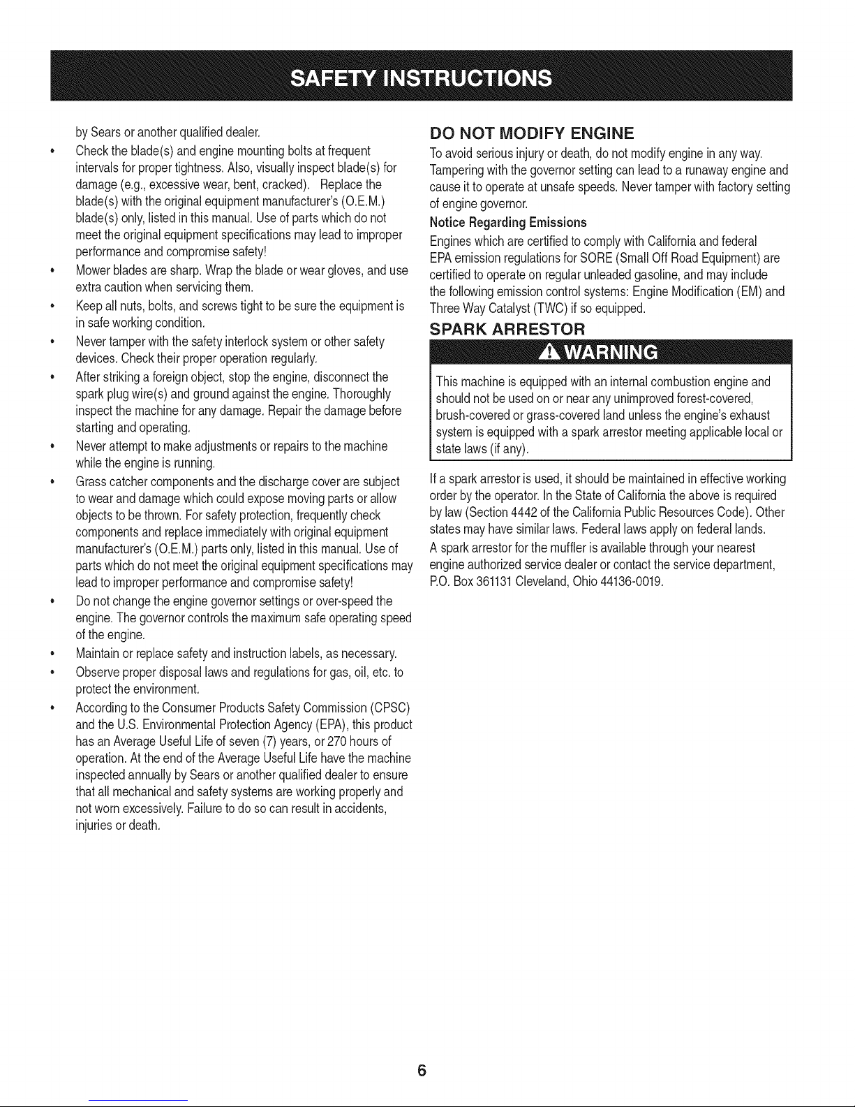
DO NOT MODIFY ENGINE
Toavoid seriousinjuryor death,do notmodifyengineinanyway.
Tamperingwiththe governorsettingcanleadto a runawayengineand
causeitto operateat unsafespeeds.Nevertamperwithfactorysetting
ofenginegovernor.
Notice RegardingEmissions
Engineswhicharecertifiedto complywithCaliforniaandfederal
EPAemissionregulationsfor SORE(SmallOffRoadEquipment)are
certifiedto operateonregularunleadedgasoline,andmayinclude
thefollowingemissioncontrolsystems:EngineModification(EM)and
ThreeWayCatalyst(TWO)if soequipped.
SPARK ARRESTOR
Thismachineisequippedwithan internalcombustionengineand
shouldnot beusedonor nearanyunimprovedforest-covered,
brush-coveredor grass-coveredlandunlesstheengine'sexhaust
systemisequippedwitha sparkarrestormeetingapplicablelocalor
statelaws(if any).
Ifa sparkarrestoris used,it shouldbe maintainedin effectiveworking
orderbythe operator.IntheStateof Californiatheaboveis required
bylaw (Section4442of the CaliforniaPublicResourcesCode).Other
statesmayhavesimilarlaws.Federallawsapplyonfederallands.
A sparkarrestorforthe muffleris availablethroughyournearest
engineauthorizedservicedealeror contacttheservicedepartment,
RO.Box361131Cleveland,Ohio44136-0019.
6
Page 7
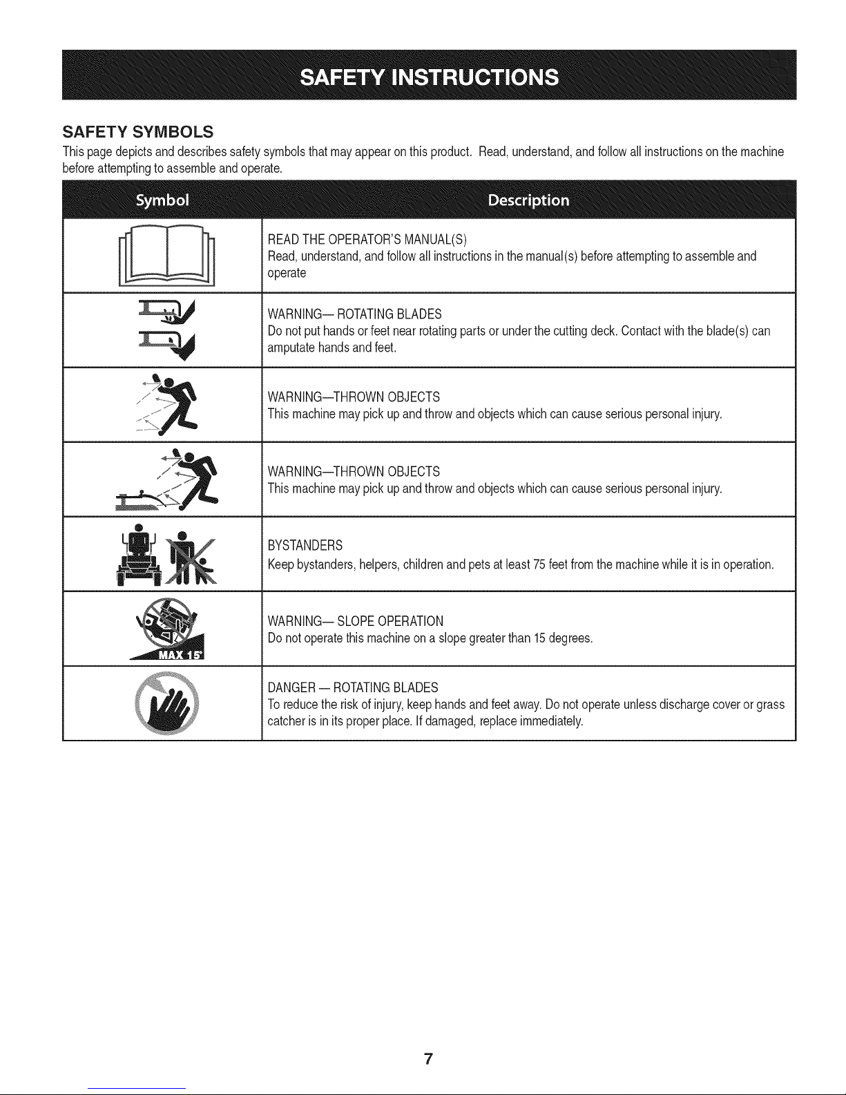
SAFETY SYMBOLS
Thispagedepictsanddescribessafetysymbolsthatmayappearonthis product.Read,understand,andfollowallinstructionson themachine
beforeattemptingtoassembleandoperate.
READTHEOPERATOR'SMANUAL(S)
Read,understand,andfollowall instructionsinthemanual(s)beforeattemptingto assembleand
operate
WARNING--ROTATINGBLADES
Donot puthandsor feetnearrotatingpartsor underthecuttingdeck.Contactwiththeblade(s)can
amputatehandsandfeet.
sJ / _
®
WARNING--THROWNOBJECTS
Thismachinemaypickupandthrowandobjectswhichcancauseseriouspersonalinjury.
WARNING--THROWNOBJECTS
Thismachinemaypickupandthrowandobjectswhichcancauseseriouspersonalinjury.
BYSTANDERS
Keepbystanders,helpers,childrenandpetsatleast75feetfromthemachinewhileitis inoperation.
WARNING--SLOPEOPERATION
Donot operatethismachineona slopegreaterthan15degrees.
DANGER-- ROTATINGBLADES
Toreducetheriskof injury,keephandsandfeetaway.Donotoperateunlessdischargecoveror grass
catcheris in itsproperplace.Ifdamaged,replaceimmediately.
7
Page 8
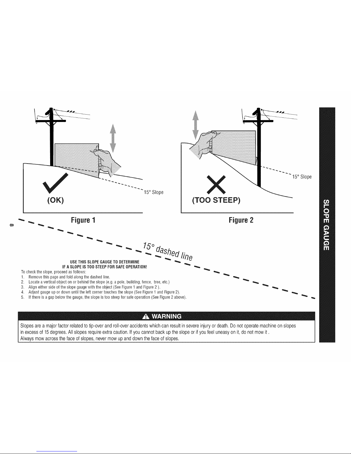
(OK)
15° Slope
X
(TOO STEEP)
15° Slope
'_. _ Figure1
USETHISSLOPEGAUGETODETERMINE
IFASLOPEISTOOSTEEPFORSAFEOPERATION!
Tocheckthe slope,proceedasfollows:
1. Removethis pageandfold alongthe dashedline.
2. Locatea verticalobject onor behindthe slope(e.g.a pole,building,fence, tree,etc.)
3. Align eitherside of theslopegaugewith the object(SeeFigure1and Figure2).
4. Adjust gaugeupor downuntilthe left cornertouchesthe slope(SeeFigure1and Figure2).
5.
15°
dashedline
If there isagap belowthe gauge,theslope is too steepfor safeoperation(SeeFigure2 above).
Figure2
Slopesare a majorfactor relatedtotip-over and roll-over accidents whichcan resultin severeinjury or death.Do not operatemachine on slopes
in excessof 15 degrees.All slopesrequire extracaution. If you cannotback up the slope or ifyou feeluneasyon it,do not mow it.
Always mowacross the faceof slopes, never mowup and downthe faceof slopes.
Page 9
SET-UP
Moving The Riding mower Manually
Yourridingmower'stransmissionisequippedwithahydrostaticrelief
valveforoccasionswhenitisnecessaryto movethe ridingmower
manually.Openingthisvalvepermitsthefluidinthe transmissionto
bypassitsnormalroute,allowingthereartiresto "freewheel."Toopen
thehydrostaticreliefvalve,proceedasfollows:
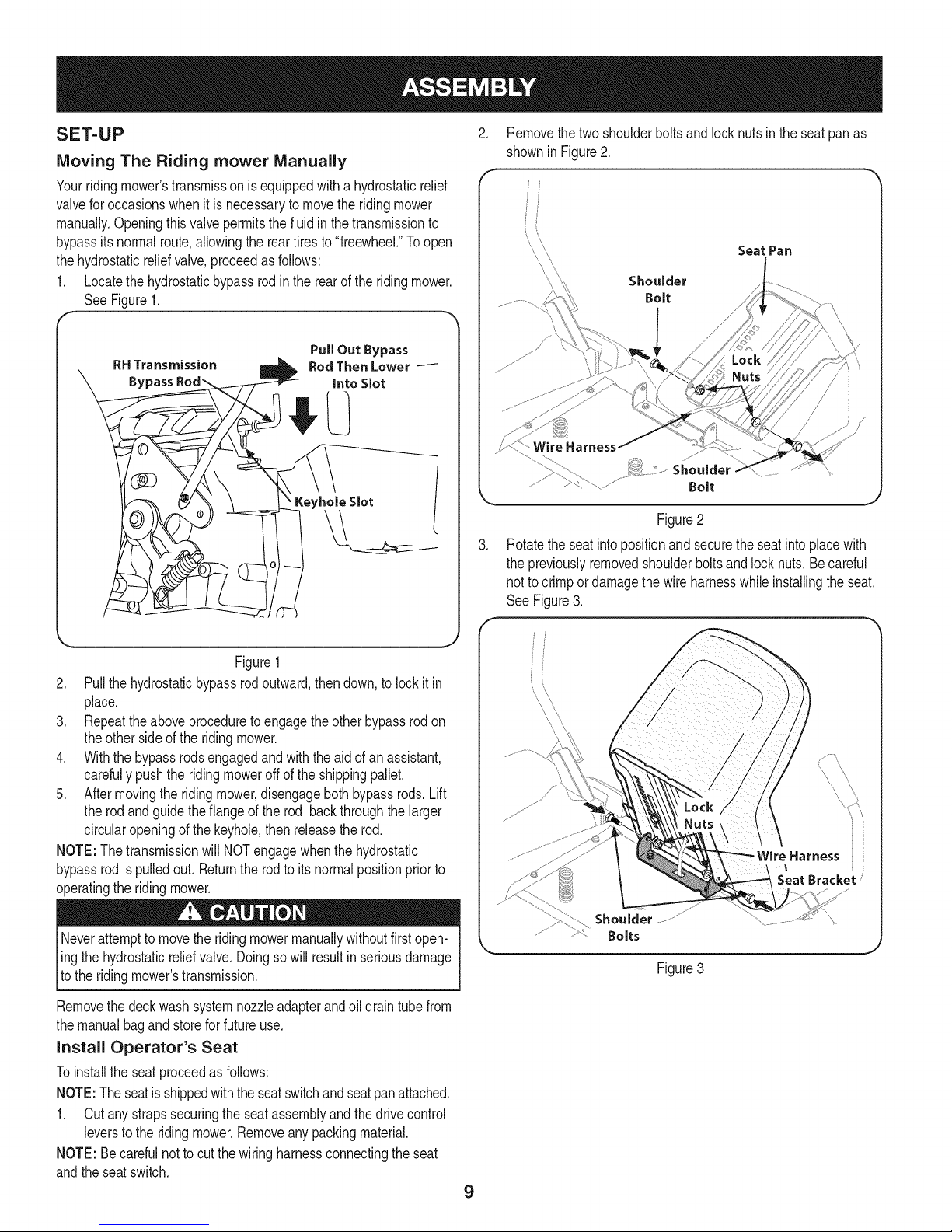
1. Locatethehydrostaticbypassrodintherearoftheridingmower.
SeeFigure1.
Removethetwoshoulderboltsandlocknutsin theseatpanas
showninFigure2.
Seat Pan
Shoulder
Bolt
RH Transmission
Bypass
RodThenLower
IntoSlot
Keyhole Slot
Figure1
2. Pullthehydrostaticbypassrodoutward,thendown,tolockit in
place.
3. Repeattheaboveproceduretoengagetheotherbypassrodon
theother sideof the ridingmower.
4. Withthe bypassrodsengagedandwiththeaidofanassistant,
carefullypushtheridingmoweroffof theshippingpallet.
5. Aftermovingthe ridingmower,disengagebothbypassrods.Lift
therodandguidethe flangeof therod backthroughthe larger
circularopeningof thekeyhole,then releasetherod.
NOTE:The transmissionwillNOTengagewhenthehydrostatic
bypassrodis pulledout. Returnthe rodto itsnormalpositionpriorto
operatingthe ridingmower.
PullOut Bypass
Shoulder
Bolt
Figure2
.
Rotatetheseatintopositionandsecuretheseatintoplacewith
thepreviouslyremovedshoulderboltsand locknuts.Becareful
notto crimpordamagethewireharnesswhileinstallingtheseat.
See Figure3.
iHarness ii
Seat Bracket /
Neverattemptto movetheridingmowermanuallywithoutfirstopen-
ling thehydrostaticr,elief valve.Doingsowill resultinseriousdamage
[to theridingmowers transmission.
Removethedeckwashsystemnozzleadapterandoildraintubefrom
themanualbagandstoreforfutureuse.
Install Operator's Seat
Toinstallthe seatproceedasfollows:
NOTE:Theseatisshippedwiththe seatswitchandseatpanattached.
1. Cutanystrapssecuringtheseatassemblyandthedrivecontrol
leverstothe ridingmower.Removeanypackingmaterial.
NOTE:Becarefulnottocut thewiringharnessconnectingtheseat
andtheseatswitch.
Shoulder
Bolts
Figure 3
9
Page 10
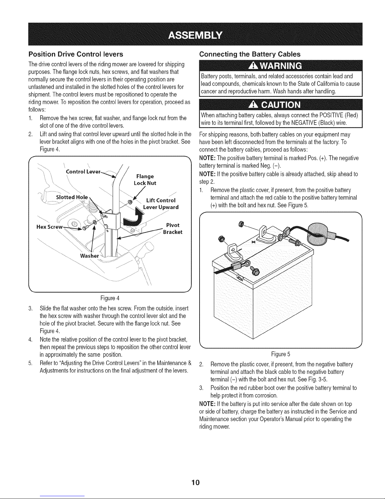
Position Drive Control levers
Thedrivecontrolleversof theridingmowerareloweredforshipping
purposes.Theflangelocknuts,hex screws,andflatwashersthat
normallysecurethe controlleversintheiroperatingpositionare
unfastenedandinstalledintheslottedholesofthecontrolleversfor
shipment.Thecontrolleversmustbe repositionedtooperatethe
ridingmower.Torepositionthecontrolleversforoperation,proceedas
follows:
1. Removethehexscrew,flat washer,andflangelocknutfromthe
slotofoneof thedrivecontrollevers.
2. Liftand swingthatcontrolleverupwarduntiltheslottedholeinthe
leverbracketalignswithoneof theholesinthepivotbracket.See
Figure4.
\
SlottedHole
Pivot
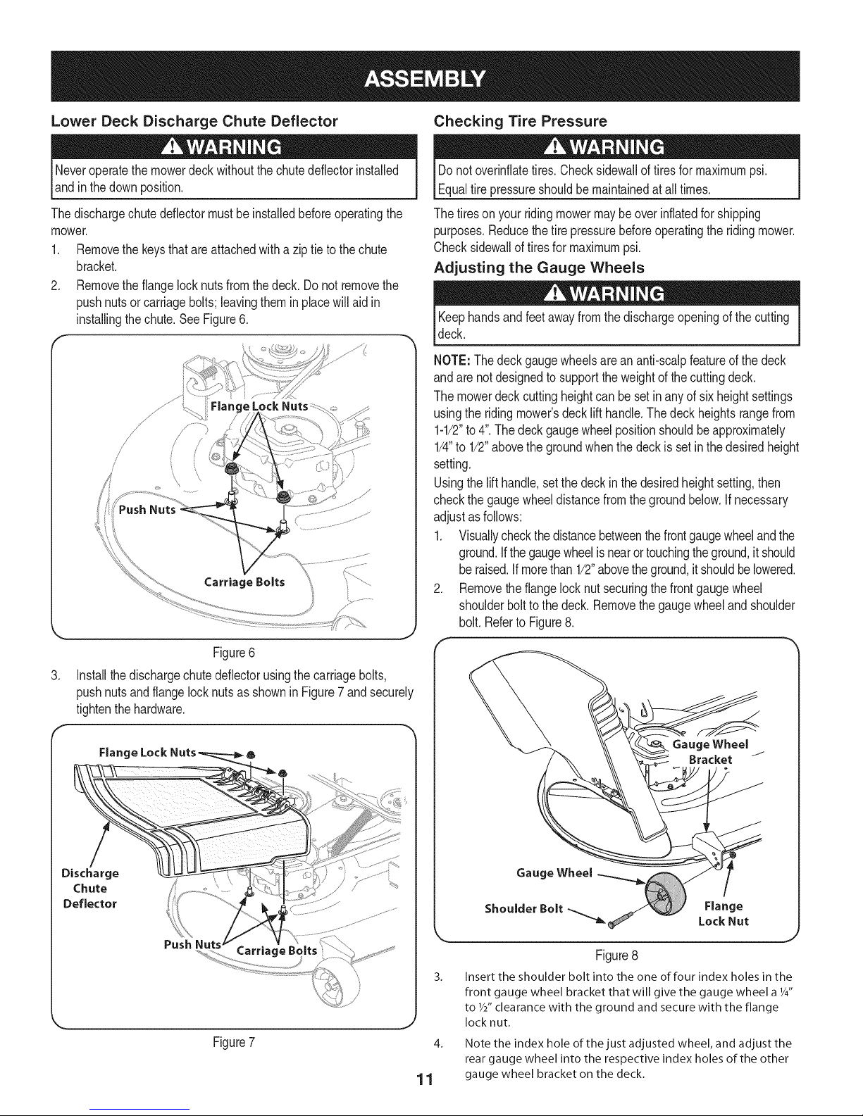
Connecting the Battery Cables
Batteryposts,terminals,and relatedaccessoriescontainleadand
leadcompounds,chemicalsknownto theStateof Californiato cause
cancerand reproductiveharm.Washhandsafterhandling.
Whenattachingbatterycables,alwaysconnectthePOSITIVE(Red)
wireto itsterminalfirst,followedby theNEGATIVE(Black)wire.
Forshippingreasons,bothbatterycableson yourequipmentmay
havebeenleftdisconnectedfromtheterminalsatthe factory.To
connectthe batterycables,proceedasfollows:
NOTE:ThepositivebatteryterminalismarkedPos.(+).Thenegative
batteryterminalismarkedNeg.(-).
NOTE:If the positivebatterycable isalreadyattached,skipaheadto
step2.
1. Removetheplasticcover,ifpresent,fromthe positivebattery
terminalandattachthe redcableto thepositivebatteryterminal
(+)withtheboltandhexnut.SeeFigure5.
/
\
\\
\\
Figure4
3. Slidetheflatwasherontothe hexscrew.Fromtheoutside,insert
thehexscrewwithwasherthroughthecontrolleverslotandthe
holeofthe pivotbracket.Securewiththe flangelocknut.See
Figure4.
4. Notethe relativepositionofthecontrollevertothepivotbracket,
thenrepeatthepreviousstepsto repositiontheothercontrollever
inapproximatelythe same position.
5. Referto"AdjustingtheDriveControlLevers"intheMaintenance&
Adjustmentsforinstructionsonthefinaladjustmentofthelevers.
Figure5
2. Removetheplasticcover,ifpresent,fromthe negativebattery
terminalandattachthe blackcableto thenegativebattery
terminal(-) withtheboltand hexnut.SeeFig.3-5.
3. Positiontheredrubberbootoverthe positivebatteryterminalto
helpprotectitfromcorrosion.
NOTE:If the batteryisputintoserviceafterthe dateshownon top
or sideof battery,chargethebatteryasinstructedinthe Serviceand
MaintenancesectionyourOperator'sManualpriortooperatingthe
ridingmower.
10
Page 11
Lower Deck Discharge Chute Deflector Checking Tire Pressure
Neveroperatethemowerdeckwithoutthechutedeflectorinstalled
andinthedownposition.
Thedischargechutedeflectormustbe installedbeforeoperatingthe
mower.
1. Removethe keysthatareattachedwitha zip tieto thechute
bracket.
2. Removetheflangelocknutsfromthedeck.Donotremovethe
pushnutsor carriagebolts;leavingthemin placewill aidin
installingthe chute.SeeFigure6.
,//
/
/
/
/
/
Carriage Bolts
Donot overinflatetires.Checksidewallof tiresformaximumpsi.
Equaltire pressureshouldbemaintainedatall times.
Thetiresonyour ridingmowermaybe overinflatedfor shipping
purposes.Reducethetirepressurebeforeoperatingtheridingmower.
Checksidewallof tiresfor maximumpsi.
Adjusting the Gauge Wheels
Keephandsandfeetawayfromthe dischargeopeningof thecutting
deck.
NOTE:Thedeckgaugewheelsarean anti-scalpfeatureof the deck
andare notdesignedtosupportthe weightofthe cuttingdeck.
Themowerdeckcuttingheightcanbe setinanyof sixheightsettings
usingthe ridingmower'sdecklift handle.Thedeckheightsrangefrom
1-1/2"to4".The deckgaugewheelpositionshouldbeapproximately
1/4"to 1/2"abovethegroundwhenthedeckissetin thedesiredheight
setting.
Usingthelifthandle,setthedeckinthedesiredheightsetting,then
checkthe gaugewheeldistancefromthegroundbelow.If necessary
adjustasfollows:
1. Visuallycheckthedistancebetweenthefrontgaugewheelandthe
ground.Ifthe gaugewheelisnearortouchingtheground,itshould
be raised.If morethan1/2"abovetheground,itshouldbelowered.
2. Removetheflangelocknutsecuringthefrontgaugewheel
shoulderbolttothe deck.Removethegaugewheelandshoulder
bolt. RefertoFigure8.
Figure6
3. Installthedischargechutedeflectorusingthecarriagebolts,
pushnutsandflangelocknutsasshownin Figure7 andsecurely
tightenthehardware.
Flange Lock 6
Discharge
Chute
Deflector
Push
Carriage Bc
Figure7
Gauge Wheel
Gauge Wheel
ShoulderBolt_ LockNut
Flange
Figure8
3_
Insert the shoulder bolt into the one of four index holes in the
front gauge wheel bracket that will give the gauge wheel a Y4"
to W' clearance with the ground and secure with the flange
J
1 1 gauge wheel bracket on the deck.
locknut.
4. Note the index hole of the just adjusted wheel, and adjust the
rear gauge wheel into the respective index holes of the other
Page 12
Adjusting the Seat
Toadjustthe positionofthe seat,pullupand holdthe seatadjustment
lever.Slidetheseatforwardor rearwardto thedesiredposition;then
releasetheadjustmentlever.Makesureseatislockedintoposition
beforeoperatingthe ridingmower.See Figure9.
5. Replacethefuelcapandtightensecurely.Wipeupspilledfuel
beforestartingengine.IffuelisspilledDONOTstartengine.Move
ridingmowerawayfromareaof spillage.Avoidcreatinganysource
ofignitionuntilfuelvaporsaregone.
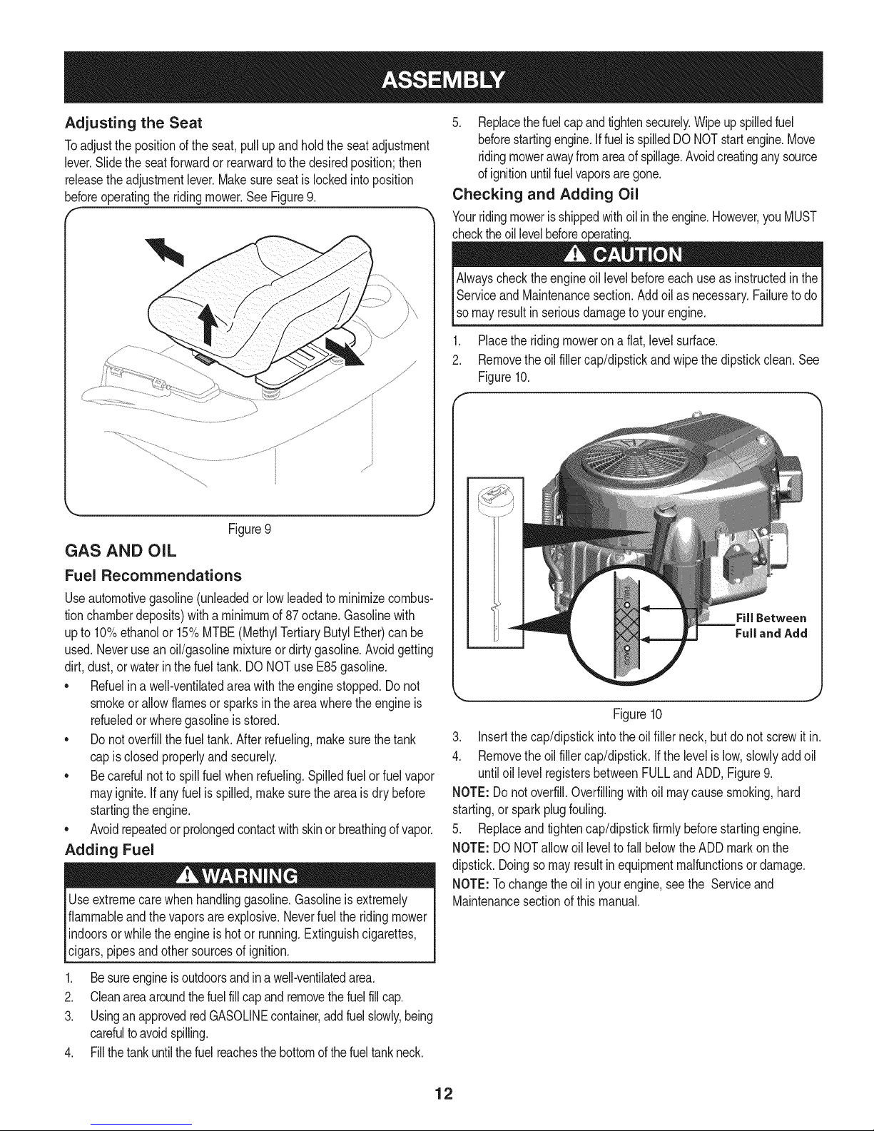
Checking and Adding Oil
Yourridingmoweris shippedwithoilintheengine.However,youMUST
m J
Figure9
GAS AND OIL
Fuel Recommendations
Useautomotivegasoline(unleadedor low leadedtominimizecombus-
tionchamberdeposits)witha minimumof87octane.Gasolinewith
upto 10%ethanolor 15%MTBE(MethylTertiaryButylEther)canbe
used.Neveruse anoil/gasolinemixtureordirtygasoline.Avoidgetting
dirt,dust,or waterin the fueltank. DONOTuse E85gasoline.
• Refuelina well-ventilatedareawiththe enginestopped.Donot
smokeorallowflamesorsparksintheareawheretheengineis
refueledorwheregasolineis stored.
Donotoverfillthefuel tank.Afterrefueling,makesurethetank
capis closedproperlyandsecurely.
Becarefulnotto spillfuelwhenrefueling.Spilledfuelor fuelvapor
mayignite.Ifanyfuel isspilled,makesuretheareais drybefore
startingtheengine.
Avoidrepeatedorprolongedcontactwithskinor breathingof vapor.
Adding Fuel
Useextremecarewhenhandlinggasoline.Gasolineisextremely
flammableandthevaporsareexplosive.Neverfuelthe ridingmower
indoorsorwhiletheengineis hotor running.Extinguishcigarettes,
cigars,pipesand othersourcesofignition.
checkthe engineoil levelbeforeeachuseasinstructedinthe IAlways
Serviceand Maintenancesection.Addoilas necessary.Failuretodo I
[so mayresut nser ousdamagetoyourengne. J
1. Placetheridingmoweron a flat,levelsurface.
2. Removetheoilfillercap/dipstickandwipethedipstickclean.See
Figure10.
Figure10
3. Insertthecap/dipstickintothe oilfillerneck,butdonot screwit in.
4. Removetheoilfillercap/dipstick.Ifthe levelislow,slowlyaddoil
untiloillevel registersbetweenFULLandADD,Figure9.
NOTE:Do notoverfill.Overfillingwithoil maycausesmoking,hard
starting,or sparkplugfouling.
5. Replaceandtightencap/dipstickfirmly beforestartingengine.
NOTE:DO NOTallowoil leveltofall belowthe ADDmarkonthe
dipstick.Doingsomayresultinequipmentmalfunctionsor damage.
NOTE:Tochangetheoil inyourengine,seethe Serviceand
Maintenancesectionof thismanual.
I
1. Besureengineisoutdoorsandin awell-ventilatedarea.
2. Cleanareaaroundthefuelfillcapandremovethefuelfillcap.
3. Usingan approvedredGASOLINEcontainer,addfuelslowly,being
carefulto avoidspilling.
4. Fillthetankuntilthefuelreachesthebottomofthefueltankneck.
12
Page 13
Deck Lift
Deck Height Handle
Throttle/Choke Control
Hour Meter/
indicator Panel
SeatAdjustmentLever
FuelTankCap
Parking
O
H
// _ / -PTOSwitch
LH Drive RH Drive nition Switch
Control Lever Control Lever
Cup Holder
Storage Tray
Figure11
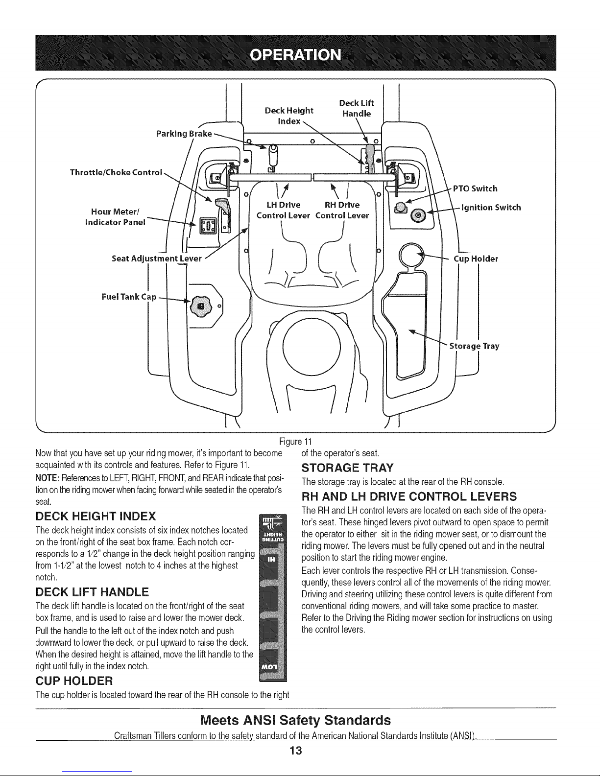
Nowthat youhavesetup yourridingmower,it'simportanttobecome ofthe operator'sseat.
acquaintedwith itscontrolsandfeatures.Referto Figure11.
NOTE:ReferencestoLEFT,RIGHT,FRONT,andREARindicatethatposi-
tionontheridingmowerwhenfacingforwardwhileseatedintheoperator's
seat.
DECK HEIGHT iNDEX
Thedeckheightindexconsistsof sixindexnotcheslocated
onthefront/rightof theseatboxframe.Eachnotchcor-
respondsto a 1/2"changeinthedeck heightpositionranging
from1-1/2"atthe lowestnotchto 4inchesatthehighest
notch.
DECK LiFT HANDLE
Thedecklift handleis locatedon the front!rightof the seat
boxframe,andisusedto raiseand lowerthemowerdeck.
Pullthehandletotheleftoutoftheindexnotchandpush
STORAGE TRAY
Thestoragetrayislocatedatthe rearofthe RHconsole.
RH AND LH DRIVE CONTROL LEVERS
TheRHandLH controlleversarelocatedon eachsideofthe opera-
tor'sseat.Thesehingedleverspivotoutwardtoopenspacetopermit
theoperatortoeither sitin theridingmowerseat,orto dismountthe
ridingmower.Theleversmustbefullyopenedoutand intheneutral
positionto starttheridingmowerengine.
Eachlevercontrolsthe respectiveRHorLH transmission.Conse-
quently,theseleverscontrolallof themovementsof theridingmower.
Drivingand steeringutilizingthesecontrolleversis quitedifferentfrom
conventionalridingmowers,andwill takesomepracticetomaster.
Refertothe Drivingthe Ridingmowersectionfor instructionsonusing
thecontrollevers.
downwardto lowerthedeck,orpullupwardto raisethedeck.
Whenthedesiredheightisattained,movethelifthandleto the
rightuntilfullyintheindexnotch.
CUP HOLDER
Thecup holderislocatedtowardtherearofthe RHconsoletotheright
Meets ANSi Safety Standards
CraftsmanTillersconformto thesafetystandardoftheAmericanNationalStandardsInstitute(ANSI)
13
Page 14
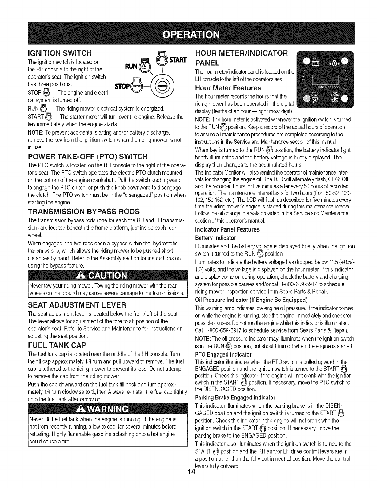
iGNiTiON SWITCH
Theignitionswitchis locatedon
theRHconsoleto therightofthe
operator'sseat.Theignitionswitch
hasthree positions.
STOP_ -- Theengineandelectri-
calsystemisturnedoff.
RUN_ -- Theridingmowerelectricalsystemisenergized.
START_ -- Thestartermotorwillturnovertheengine.Releasethe
keyimmediatelywhentheenginestarts
NOTE:Topreventaccidentalstartingand/or batterydischarge,
removethe keyfromtheignitionswitchwhenthe ridingmowerisnot
inuse.
RUN_ I
POWER TAKE-OFF (PTO) SWITCH
ThePTOswitchislocatedonthe RHconsoletothe rightof theopera-
tor'sseat.ThePTOswitchoperatestheelectricPTOclutchmounted
onthebottomoftheenginecrankshaft.Pullthe switchknobupward
toengagethe PTOclutch,or pushtheknob downwardto disengage
theclutch.The PTOswitchmustbeinthe"disengaged"positionwhen
startingtheengine.
TRANSMiSSiON BYPASS RODS
Thetransmissionbypassrods(onefor eachthe RHandLHtransmis-
sion)arelocatedbeneaththeframeplatform,justinsideeach rear
wheel.
Whenengaged,the two rodsopena bypasswithinthe hydrostatic
transmissions,whichallowstheridingmowerto be pushedshort
distancesby hand.Referto theAssemblysectionforinstructionson
usingthe bypassfeature.
Nevertowyourridingmower.Towingthe ridingmowerwiththe rear
wheelsonthe groundmaycauseseveredamageto thetransmissions.
SEAT ADJUSTMENT LEVER
Theseatadjustmentleverislocatedbelowthefront!leftoftheseat.
Theleverallowsforadjustmentoftheforetoaft positionofthe
operator'sseat.Referto Serviceand Maintenanceforinstructionson
adjustingthe seatposition.
FUEL TANK CAP
Thefuel tankcapislocatednearthemiddleoftheLHconsole.Turn
thefill capapproximately1/4turnandpull upwardtoremove.Thefuel
capistetheredto the ridingmowerto preventitsloss.Do notattempt
toremovethecapfromthe ridingmower.
Pushthecapdownwardonthe fueltankfill neckand turnapproxi-
mately1/4turnclockwisetotightenAlwaysre-installthe fuelcap tightly
ontothe fueltankafter removing.
Neverfillthe fueltankwhentheengineis running.Ifthe engineis
hotfrom recentlyrunning,allowtocoolforseveralminutesbefore
refueling.Highlyflammablegasolinesplashingontoa hot engine
couldcausea fire.
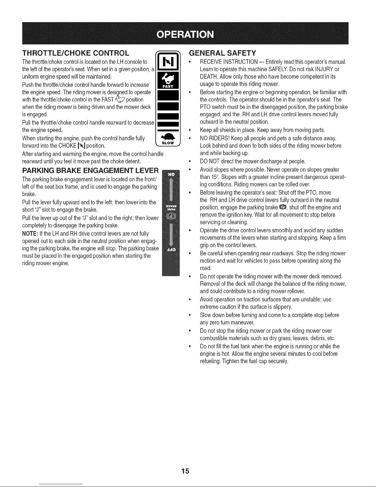
HOUR METER/INDICATOR
PANEL
Thehourmeter/indicatorpanelislocatedonthe
LHconsoletotheIdtd theoperator'sseat.
Hour Meter Features
Thehourmeterrecordsthehoursthatthe
ridingmowerhasbeenoperatedinthedigital
display(tenthsofanhour-- rightmostdigit).
NOTE:Thehourmeterisactivatedwhenevertheignitionswitchisturned
totheRUN_ position.Keepa recordof theactualhoursof operation
toassureallmaintenanceproceduresarecompletedaccordingtothe
instructionsintheServiceandMaintenancesectionof thismanual.
Whenkeyis turnedto theRUN_ position,thebatteryindicatorlight
brieflyilluminatesandthebatteryvoltageis brieflydisplayed.The
displaythenchangestotheaccumulatedhours.
TheIndicatorMonitorwillalsoremindtheoperatorofmaintenanceinter-
valsforchangingtheengineoil.TheLCDwillalternatelyflash,CHG;OIL
andtherecordedhoursforfiveminutesafterevery50hoursof recorded
operation.Themaintenanceintervallastsfortwohours(from50-52,100-
102,150-152,etc.).TheLCDwillflashasdescribedforfiveminutesevery
timetheridingmower'sengineisstartedduringthismaintenanceinterval.
FollowtheoilchangeintervalsprovidedintheServiceandMaintenance
sectionofthisoperator'smanual.
indicator Panel Features
Battery Indicator
Illuminatesandthe batteryvoltageisdisplayedbrieflywhenthe ignition
switchitturnedtothe RUN_ position.
Illuminatesto indicatethe batteryvoltagehasdroppedbelow11.5(+0.5/-
1.0)volts,andthevoltageis displayedonthe hourmeter.Ifthisindicator
anddisplaycomeonduringoperation,checkthebatteryandcharging
systemforpossiblecausesand/orcall1-800-659-5917to schedule
ridingmowerinspectionservicefromSearsParts& Repair.
Oil PressureIndicator (if EngineSo Equipped)
Thiswarninglampindicateslowengineoilpressure.Iftheindicatorcomes
onwhiletheengineis running,stoptheengineimmediatelyandcheckfor
possiblecauses.Donotruntheenginewhilethisindicatorisilluminated.
Call1-800-659-5917toscheduleservicefromSearsParts& Repair.
NOTE:Theoil_ressureindicatormayilluminatewhentheignitionswitch
isin the RUN0 position,butshouldturnoffwhentheengineisstarted.
PTOEngagedIndicator
ThisindicatorilluminateswhenthePTOswitchis pulledupwardinthe
ENGAGEDpositionandtheignitionswitchisturnedtothe START
position.Checkthisindicatoriftheenginewillnotcrankwiththeignition
switchinthe START_ position.Ifnecessary,movethePTOswitchto
theDISENGAGEDposition.
ParkingBrake Engaged Indicator
Thisindicatorilluminateswhenthe parkingbrakeisin the DISEN-
GAGEDpositionandtheignitionswitchisturnedtothe START
position.Checkthis indicatoriftheenginewill notcrankwiththe
ignitionswitchinthe START_ position.Ifnecessary,movethe
parkingbraketo theENGAGEDposition.
Thisindicatoralsoilluminateswhentheignitionswitchisturnedtothe
START_ positionandtheRHand/orLHdrivecontrolleversare in
a positionotherthanthefullyout in neutralposition.Movethe control
leversfullyoutward.
14
Page 15
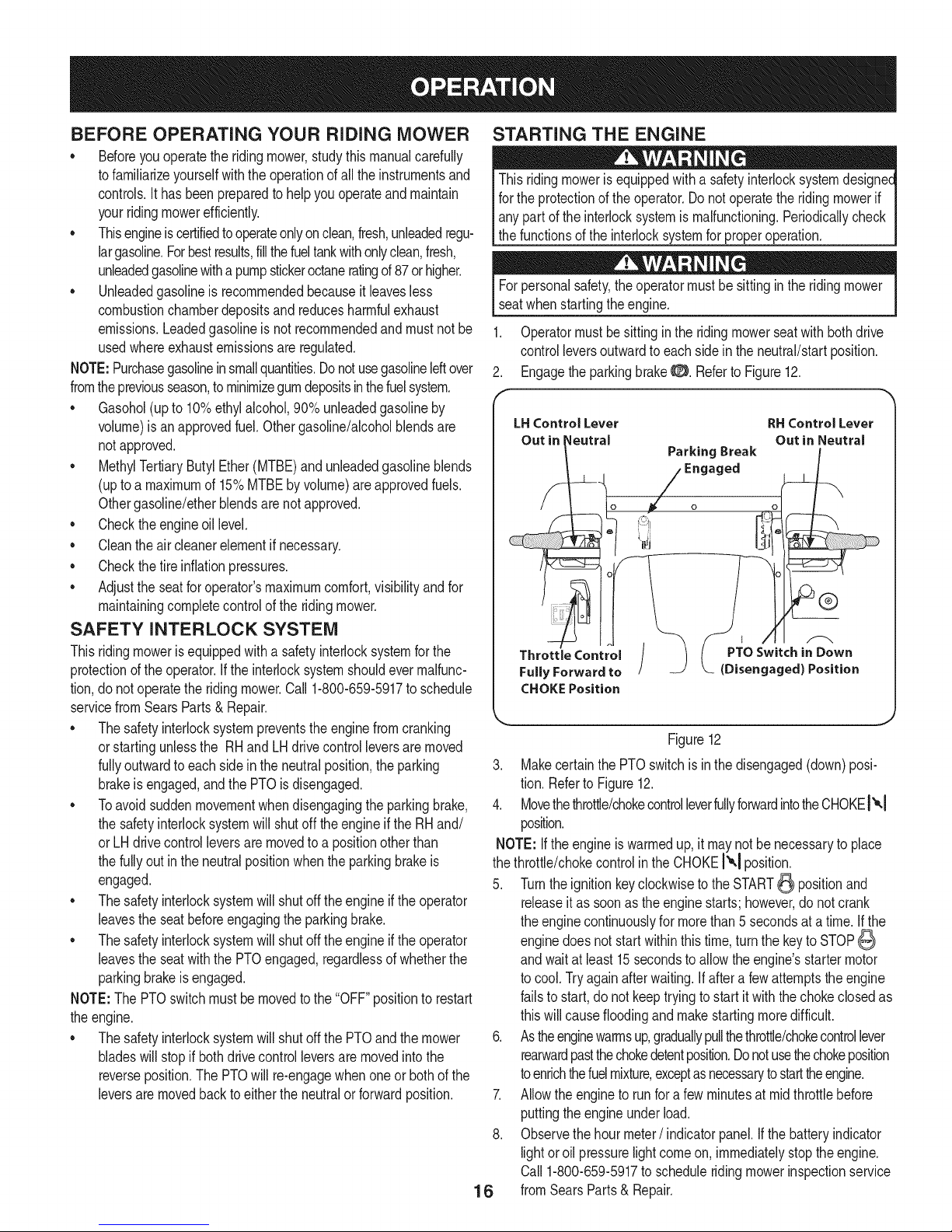
THROTTLE/CHOKE CONTROL
Thethrottle/chokecontrolislocatedonthe LHconsoleto
theleftof theoperator'sseat.Whensetina givenposition,a
uniformenginespeedwill bemaintained.
Pushthethrottle/chokecontrolhandleforwardtoincrease
theenginespeed.Theridingmowerisdesignedtooperate
withthethrottle/chokecontrolintheFAST_ position
whentheridingmoweris beingdrivenandthemowerdeck
isengaged.
Pullthethrottle/chokecontrolhandlerearwardtodecrease
theenginespeed.
Whenstartingtheengine,pushthecontrolhandlefully
forwardintothe CHOKEI'_,1position.
Afterstartingandwarmingtheengine,movethe controlhandle
rearwarduntilyoufeel it movepastthechokedetent.
PARKING BRAKE ENGAGEMENT LEVER
Theparkingbrakeengagementleveris locatedonthefront/
leftofthe seatboxframe,andis usedtoengagethe parking
brake.
Pulltheleverfullyupwardandtothe left;thenlowerintothe
short"J"slottoengagethe brake.
Pulltheleverupoutof the"J"slotandto theright;then lower
completelyto disengagetheparkingbrake.
NOTE:Ifthe LHandRHdrivecontrolleversarenotfully
openedoutto eachsidein theneutralpositionwhenengag-
ingtheparkingbrake,theenginewill stop.The parkingbrake
mustbe placedin theengagedpositionwhenstartingthe
ridingmowerengine.
GENERAL SAFETY
• RECEIVEINSTRUCTION-- Entirelyreadthisoperator'smanual.
Learnto operatethismachineSAFELY.Donot riskINJURYor
DEATH.Allowonlythosewho havebecomecompetentin its
usageto operatethisridingmower.
• Beforestartingtheengineor beginningoperation,be familiarwith
thecontrols.Theoperatorshouldbein theoperator'sseat.The
PTOswitchmustbein thedisengagedposition,theparkingbrake
engaged,andthe RHand LHdrivecontrolleversmovedfully
outwardin theneutralposition.
• Keepallshieldsin place.Keepawayfrommovingparts.
• NORIDERS!Keepall peopleandpetsa safedistanceaway.
Lookbehindanddowntobothsidesoftheridingmowerbefore
andwhilebackingup.
• DONOTdirectthemowerdischargeatpeople.
• Avoidslopeswherepossible.Neveroperateon slopesgreater
than15°.Slopeswitha greaterinclinepresentdangerousoperat-
ing conditions.Ridingmowerscanbe rolledover.
• Beforeleavingtheoperator'sseat:ShutoffthePTO,move
the RHand LHdrivecontrolleversfullyoutwardin the neutral
position,engagetheparkingbrake_:_, shutoff theengineand
removethe ignitionkey.Waitforall movementto stopbefore
servicingorcleaning.
• Operatethedrivecontrolleverssmoothlyandavoidanysudden
movementsofthe leverswhenstartingandstopping.Keepafirm
gripon thecontrollevers.
• Becarefulwhenoperatingnearroadways.Stoptheridingmower
motionandwaitforvehiclestopassbeforeoperatingalongthe
road.
• Donotoperatetheridingmowerwiththe mowerdeckremoved.
Removalofthe deckwillchangethebalanceofthe ridingmower,
andcouldcontributetoa ridingmowerrollover.
• Avoidoperationontractionsurfacesthatare unstable;use
extremecautionif thesurfaceis slippery.
• Slowdown beforeturningandcometo a completestopbefore
anyzeroturnmaneuver.
• Donotstoptheridingmoweror parktheridingmowerover
combustiblematerialssuchasdry grass,leaves,debris,etc.
• Donotfillthefueltankwhentheengineis runningor whilethe
engineishot.Allowtheengineseveralminutesto coolbefore
refueling.Tightenthe fuelcap securely.
15
Page 16
BEFORE OPERATING YOUR RiDiNG MOWER
• Beforeyouoperatetheridingmower,studythismanualcarefully
tofamiliarizeyourselfwiththeoperationofallthe instrumentsand
controls.Ithasbeenpreparedtohelpyouoperateandmaintain
yourridingmowerefficiently.
• Thisengineiscertifiedtooperateonlyonclean,fresh,unleadedregu-
largasoline.Forbestresults,fill thefueltankwithonlyclean,fresh,
unleadedgasolinewithapumpstickeroctaneratingof87orhigher.
• Unleadedgasolineis recommendedbecauseitleavesless
combustionchamberdepositsand reducesharmfulexhaust
emissions.Leadedgasolineis notrecommendedand mustnotbe
usedwhereexhaustemissionsareregulated.
NOTE:Purchasegasolineinsmallquantities.Donotusegasolineleftover
fromthe previousseason,tominimizegumdepositsinthefuelsystem.
• Gasohol(upto 10%ethylalcohol,90% unleadedgasolineby
volume)isanapprovedfuel.Othergasoline/alcoholblendsare
notapproved.
• MethylTertiaryButylEther(MTBE)andunleadedgasolineblends
(uptoa maximumof 15%MTBEbyvolume)areapprovedfuels.
Othergasoline/etherblendsarenotapproved.
• Checktheengineoil level.
• Cleantheair cleanerelementif necessary.
• Checkthetireinflationpressures.
• Adjusttheseatforoperator'smaximumcomfort,visibilityandfor
maintainingcompletecontrolofthe ridingmower.
SAFETY iNTERLOCK SYSTEM
Thisridingmowerisequippedwitha safetyinterlocksystemforthe
protectionoftheoperator.Ifthe interlocksystemshouldevermalfunc-
tion,donotoperatetheridingmower.Call 1-800-659-5917to schedule
servicefromSearsParts& Repair.
• Thesafetyinterlocksystempreventstheenginefromcranking
orstartingunlessthe RHand LHdrivecontrolleversaremoved
fullyoutwardto eachsidein theneutralposition,theparking
brakeisengaged,andthe PTOis disengaged.
• Toavoidsuddenmovementwhendisengagingthe parkingbrake,
thesafetyinterlocksystemwillshutoffthe engineifthe RHand/
or LHdrivecontrolleversare movedto a positionotherthan
thefullyout intheneutralpositionwhenthe parkingbrakeis
engaged.
• Thesafetyinterlocksystemwillshutofftheengineiftheoperator
leavestheseatbeforeengagingthe parkingbrake.
• Thesafetyinterlocksystemwillshutofftheengineiftheoperator
leavestheseatwiththe PTOengaged,regardlessof whetherthe
parkingbrakeisengaged.
NOTE:The PTOswitchmustbe movedto the"OFF"positionto restart
theengine.
• Thesafetyinterlocksystemwillshutoffthe PTOandthe mower
bladeswillstopif bothdrivecontrolleversare movedintothe
reverseposition.ThePTOwillre-engagewhenoneor bothof the
leversaremovedbacktoeither theneutralorforwardposition.
STARTING THE ENGINE
Thisridingmowerisequippedwitha safetyinterlocksystemdesignee
forthe protectionofthe operator.Donotoperatethe ridingmowerif
anypartofthe interlocksystemis malfunctioning.Periodicallycheck
thefunctionsofthe interlocksystemforproperoperation.
Forpersonalsafety,theoperatormustbesittingintheridingmower
seatwhenstartingtheengine.
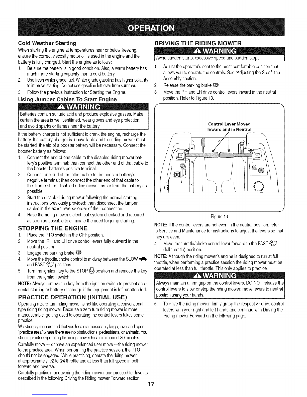
1. Operatormustbesittinginthe ridingmowerseatwithbothdrive
controlleversoutwardto eachsidein theneutral/startposition.
2. EngagetheparkingbrakeO. Referto Figure12.
LHControlLever RHControlLever
Outin I_eutral Out in Neutral
ParkingBreak
-- Engaged
ThrottleControl / ( PTOSwitchinDown
FullyForwardto / __ (Disengaged)Position
CHOKEPosition
Figure12
3. MakecertainthePTOswitchisin the disengaged(down)posi-
tion. Referto Figure12.
4. Movethethrottle/chokecontrolleverfullyforwardintotheCHOKEt"°,1
position.
NOTE:Iftheengineiswarmedup,it maynotbe necessarytoplace
thethrottle/chokecontrolinthe CHOKE!'_1position.
5. Turnthe ignitionkeyclockwisetotheSTART_ positionand
releaseitassoonasthe enginestarts;however,do not crank
theenginecontinuouslyfor morethan5 secondsata time.If the
enginedoesnot startwithinthis time,turnthe keytoSTOP
andwaitat least15secondstoallowtheengine'sstartermotor
tocool.Tryagainafterwaiting.Ifaftera fewattemptstheengine
failstostart,do not keeptryingto startit withthechokeclosedas
thiswillcausefloodingandmakestartingmoredifficult.
6. Astheenginewarmsup,graduallypullthethrottle/chokecontrollever
rearwardpastthechokedetentposition.Donotusethechokeposition
toenrichthefuelmixture,exceptasnecessarytostarttheengine.
7. Allowtheengineto runfora fewminutesatmidthrottlebefore
puttingtheengineunderload.
8. Observethehourmeter/ indicatorpanel.Ifthe batteryindicator
lightoroil pressurelightcomeon,immediatelystoptheengine.
Call1-800-659-5917toscheduleridingmowerinspectionservice
16
fromSearsParts& Repair.
Page 17
ColdWeatherStarting
Whenstartingtheengineattemperaturesnearorbelowfreezing,
ensurethecorrectviscositymotoroilisusedintheengineandthe
batteryisfullycharged.Starttheengineasfollows:
1. Besurethebatteryisingoodcondition.Also,awarmbatteryhas
muchmorestartingcapacitythanacoldbattery.
2. Usefreshwintergradefuel.Wintergradegasolinehashighervolatility
toimprovestarting.Donotusegasolineleftoverfromsummer.
3. FollowthepreviousinstructionforStartingtheEngine.
UsingJumper CablesTo Start Engine
Batteriescontainsulfuricacidandproduceexplosivegasses.Make
certaintheareaiswellventilated,wearglovesandeyeprotection,
land avod sparksor famesnearthe battery.
Ifthe batterychargeis notsufficienttocranktheengine,rechargethe
battery.Ifa batterychargeris unavailableandtheridingmowermust
be started,the aidof aboosterbatterywillbenecessary.Connectthe
boosterbatteryasfollows:
1. Connecttheendofonecabletothedisabledridingmowerbat-
tery'spositiveterminal;thenconnecttheotherendof thatcableto
theboosterbattery'spositiveterminal.
2. Connectoneendof theothercabletotheboosterbattery's
negativeterminal;thenconnecttheotherendofthatcableto
the frameof thedisabledridingmower,asfarfromthe batteryas
possible.
3. Startthedisabledridingmowerfollowingthe normalstarting
instructionspreviouslyprovided;thendisconnectthejumper
cablesin theexact reverseorderof theirconnection.
4. Havetheridingmower'selectricalsystemcheckedand repaired
assoonaspossibleto eliminatethe needforjump starting.
STOPPING THE ENGINE
1. Placethe PTOswitchinthe OFFposition.
2. Movethe RHand LHdrivecontrolleversfullyoutwardin the
neutralposition.
3. EngagetheparkingbrakeO.
4. Movethethrottle/chokecontroltomidwaybetweentheSLOW"_
andFAST_ positions.
5. Turntheignitionkeytothe STOP_ positionand removethekey
fromtheignitionswitch.
NOTE:Alwaysremovethe keyfromtheignitionswitchtopreventacci-
dentalstartingor batterydischargeiftheequipmentisleft unattended.
PRACTICE OPERATION (INITIAL USE)
Operatinga zero-turnridingmowerisnotlikeoperatingaconventional
typeridingridingmower.Becausea zeroturnridingmoweris more
maneuverable,gettingusedtooperatingthecontrolleverstakessome
practice.
Westronglyrecommendthatyoulocatea reasonablylarge,levelandopen
"practicearea"wheretherearenoobstructions,pedestrians,oranimals.You
shouldpracticeoperatingthendingmowerforaminimumof30minutes.
Carefullymove-- orhaveanexperiencedusermove--the ridingmower
tothepracticearea.Whenperformingthe practicesession,the PTO
shouldnotbeengaged.Whilepracticing,operatetheridingmower
atapproximately1/2to 3/4throttleandat lessthanfull speedinboth
forwardandreverse.
Carefullypracticemaneuveringtheridingmowerandproceedto driveas
describedin thefollowingDrivingtheRidingmowerForwardsection.
17
DRIVING THE RIDING MOWER
Avoidsuddenstarts,excessivespeedandsuddenstops. ]
1. Adjusttheoperator'sseattothe mostcomfortablepositionthat
allowsyouto operatethecontrols.See"AdjustingtheSeat" the
Assemblysection.
2. Releasetheparkingbrake_:_.
3. MovetheRHand LHdrivecontrolleversinwardin theneutral
position.Referto Figure13.
Control Lever Moved
inward and in Neutral
/
Figure13
NOTE:Ifthe controlleversarenoteven intheneutralposition,refer
to ServiceandMaintenancefor instructionstoadjustthe leverssothat
theyareeven.
4. Movethethrottle/chokecontrolleverforwardtothe FAST
(fullthrottle)position.
NOTE:Althoughtheridingmower'sengineisdesignedto runat full
throttle,whenperforminga practicesessiontheridingmowermustbe
operatedatlessthanfullthrottle.Thisonlyappliesto practice.
Alwaysmaintainafirm griponthe controllevers.DONOTreleasethe
controlleversto slowor stopthe ridingmower;moveleversto neutral
positionusingyour hands.
5. Todrive theridingmower,firmlygrasptherespectivedrivecontrol
leverswithyourrightandleft handsandcontinuewithDrivingthe
RidingmowerForwardon thefollowingpage.
Q
Page 18
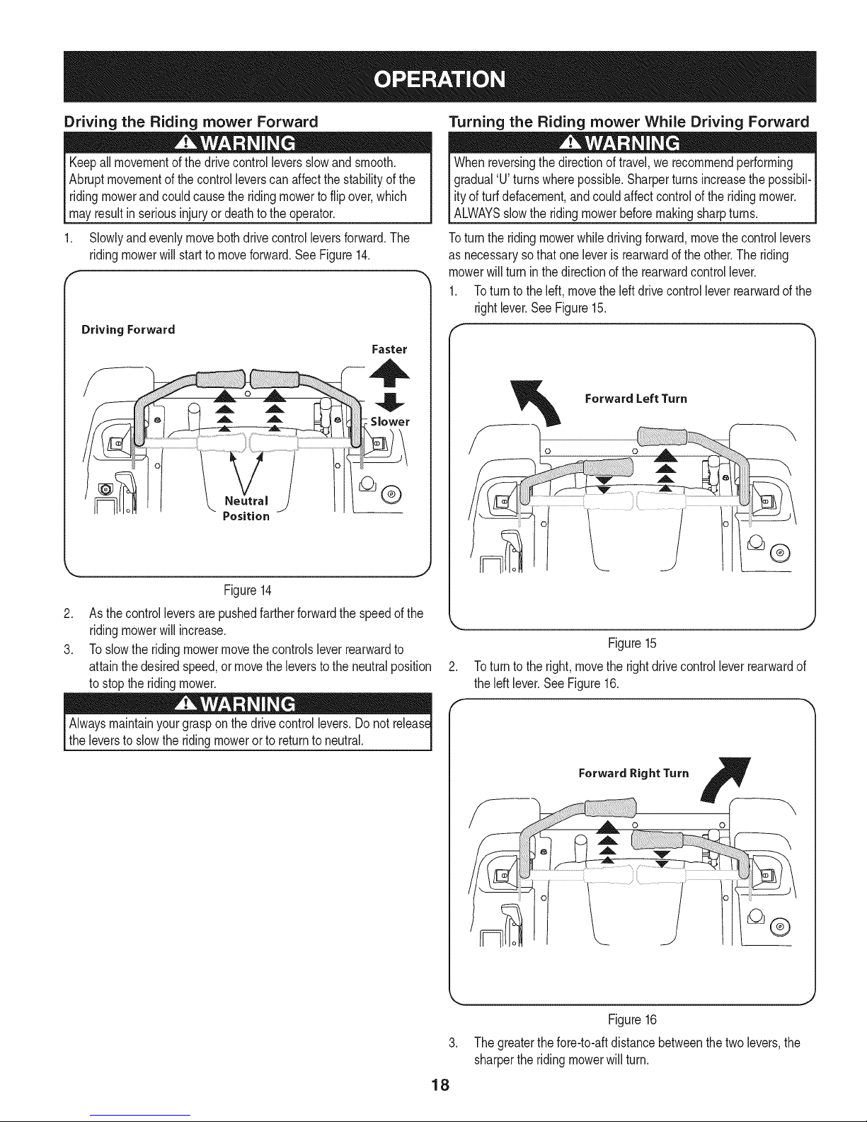
Driving the Riding mowerForward
Turning the Riding mower While Driving Forward
Keepall movementof thedrivecontrolleversslowandsmooth.
Abruptmovementofthe controlleverscanaffectthe stabilityofthe
ridingmowerandcouldcausetheridingmowerto flipover,which
mayresultin seriousinjury ordeathto theoperator.
Slowlyandevenlymovebothdrive controlleversforward.The
ridingmowerwill startto moveforward.SeeFigure14.
r
Driving Forward
Faster
Whenreversingthedirectionof travel,werecommendperforming
gradual'U' turnswherepossible.Sharperturnsincreasethepossibil-
ity ofturfdefacement,andcouldaffectcontrolofthe ridingmower.
ALWAYSslowtheridingmowerbeforemakingsharpturns.
Toturn theridingmowerwhiledrivingforward,movethecontrollevers
as necessarysothat oneleveris rearwardd the other.The riding
mowerwill turninthe directionof the rearwardcontrollever.
1. Toturntotheleft,movetheleftdrivecontrolleverrearwardofthe
rightlever.SeeFigure15.
Figure14
2. Asthecontrolleversarepushedfartherforwardthespeedofthe
ridingmowerwill increase.
3. Toslowthe ridingmowermovethecontrolsleverrearwardto
attainthedesiredspeed,ormovetheleverstotheneutralposition
tostopthe ridingmower.
Alwaysmaintainyourgraspon the drivecontrollevers.Donot release
the leversto slowthe ridingmowerorto returntoneutral.
Figure15
2. Toturn tothe right,movetherightdrivecontrollever rearwardof
theleft lever.SeeFigure16.
W
ForwardRightTurn F
-oZ-
Figure16
3. Thegreaterthefore-to-aftdistancebetweenthetwolevers,the
sharpertheridingmowerwillturn.
18
Page 19
4. Toexecutea"zeroturn"movetheturnsidedrivecontrolleverto
theinwardneutralposition,whilemovingtheothercontrollever
forward.
NOTE:Makingazeroturnongrasswillgreatlyincreasethepotential
fordefacementoftheturf.
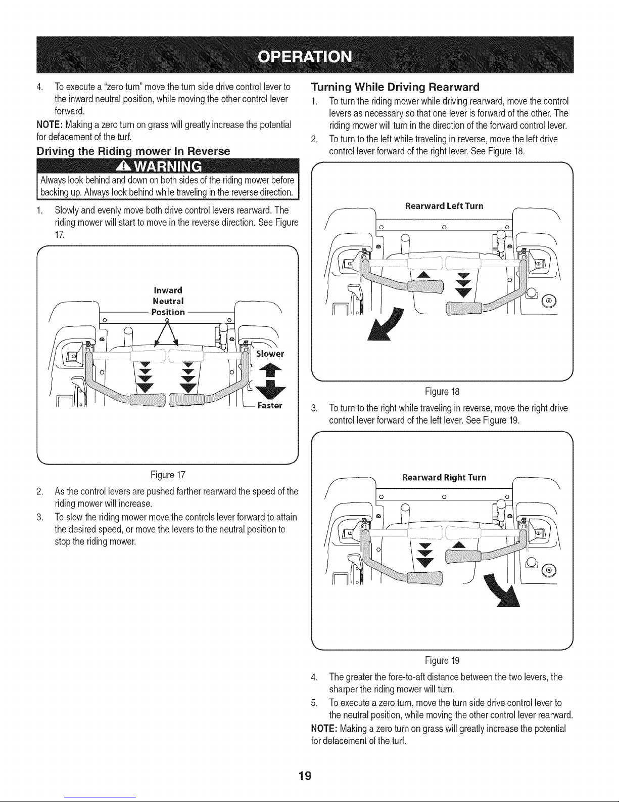
Driving the Riding mower in Reverse
Turning While Driving Rearward
1. Toturntheridingmowerwhiledrivingrearward,movethecontrol
leversasnecessaryso thatoneleverisforwardofthe other.The
ridingmowerwillturninthedirectionof theforwardcontrollever.
.
Toturn tothe leftwhiletravelinginreverse,movethe left drive
controlleverforwardofthe rightlever.See Figure18.
F
1. Slowlyandevenlymovebothdrivecontrolleversrearward.The
ridingmowerwill startto moveinthe reversedirection.SeeFigure
17.
Figure17
.
Asthecontrolleversarepushedfartherrearwardthe speedof the
ridingmowerwill increase.
3.
Toslowthe ridingmowermovethecontrolsleverforwardto attain
thedesiredspeed,or movetheleversto theneutralpositionto
stoptheridingmower.
Rearward Left Turn
0
Figure18
.
Toturn tothe rightwhiletravelinginreverse,movetherightdrive
controlleverforwardoftheleft lever.SeeFigure19.
f
Rearward Right Turn
0
®
Figure19
4. Thegreaterthefore-to-aftdistancebetweenthetwolevers,the
sharperthe ridingmowerwillturn.
5. Toexecutea zeroturn,movethe turnsidedrivecontrolleverto
theneutralposition,whilemovingtheother controlleverrearward.
NOTE:Makinga zeroturnon grasswill greatlyincreasethepotential
fordefacementoftheturf.
19
Page 20
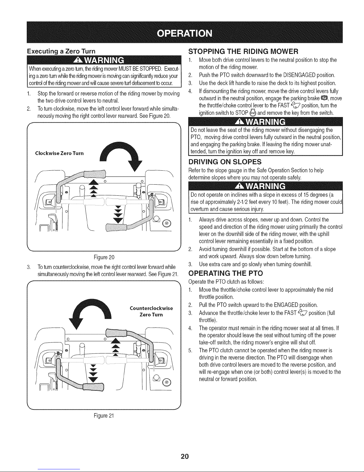
Executing a Zero Turn
ingazeroturnwhiletheridingmoweris movingcansignificantlyreduceyour
Whenexecutingazeroturn,theridingmowerMUSTBESTOPPED.Execut-
controloftheridingmowerandwillcausesevereturfdefacementtooccur.
1. Stoptheforwardor reversemotionoftheridingmowerbymoving
thetwodrivecontrolleverstoneutral.
2. Toturnclockwise,movetheleftcontrolleverforwardwhilesimulta-
neouslymovingtherightcontrolleverrearward.SeeFigure20.
Clockwise Zero Turn
Figure20
.
Toturncounterclockwise,movetherightcontrolleverforwardwhile
simultaneouslymovingtheleftcontrolleverrearward.SeeFigure21.
r
Counterclockwise
Zero Turn
STOPPING THE RIDING MOWER
1. Movebothdrivecontrolleverstothe neutralpositiontostopthe
motionof theridingmower.
2. Pushthe PTOswitchdownwardtothe DISENGAGEDposition.
3. Usethedecklift handleto raisethe decktoitshighestposition.
4. Ifdismountingtheridingmower,movethe drivecontrolleversfully
outwardintheneutralposition,engagethe parkingbrakeO, move
thethrottle/chokecontrollevertothe FAST_ position,turnthe
ignitionswitchto STOP_ andremovethekeyfromtheswitch.
Donot leavetheseatofthe ridingmowerwithoutdisengagingthe
PTO, movingdrivecontrolleversfullyoutwardin the neutralposition,
andengagingthe parkingbrake,if leavingtheridingmowerunat-
tended,turnthe ignitionkeyoffand removekey.
DRIVING ON SLOPES
Referto theslopegaugeinthe SafeOperationSectiontohelp
determineslopeswhereyoumaynot operatesafely.
Donot operateoninclineswitha slopein excessof15degrees(a
riseof approximately2-1/2feetevery10feet).The ridingmowercould
overturnandcauseseriousinjury.
1. Alwaysdriveacrossslopes,neverupanddown.Controlthe
speedanddirectionof theridingmowerusingprimarilythe control
leveronthedownhillsideofthe ridingmower,withtheuphill
controlleverremainingessentiallyina fixedposition.
2. Avoidturningdownhillif possible.Startat thebottomof a slope
andworkupward.Alwaysslowdownbeforeturning.
3. Useextracareandgo slowlywhenturningdownhill.
OPERATING THE PTO
Operatethe PTOclutchas follows:
1. Movethe throttle/chokecontrollevertoapproximatelythemid
throttleposition.
2. Pullthe PTOswitchupwardtothe ENGAGEDposition.
3. Advancethethrottle/chokelevertotheFAST_? position(full
throttle).
4. Theoperatormustremainintheridingmowerseatatalltimes.If
theoperatorshouldleavetheseatwithoutturningoffthe power
take-offswitch,theridingmower'senginewillshutoff.
5. ThePTOclutchcannotbeoperatedwhenthe ridingmoweris
drivingin the reversedirection.ThePTOwilldisengagewhen
bothdrivecontrolleversaremovedtothe reverseposition,and
willre-engagewhenone(or both)controllever(s)is movedto the
neutralorforwardposition.
Figure21
2O
Page 21
USING THE MOWER DECK
l Makecertaintheareato be mowedisfreeof debris,sticks,stones,
wireorother objectsthatcan bethrownbythe rotatingblades. ]
NOTE:Donotengagethe mowerdeckwhenloweredingrass.
Prematurewearand possiblefailureofthe 'V" beltand PTOclutch
willresult.Fullyraisethe deckormovetoa non-grassyareabefore
engagingthe mowerdeck.
1. Mowacrossslopes,notupanddown.Ifmowinga slope,startat
bottomandworkupwardtoensureturnsaremadeuphill.
2. Onthefirst passpicka pointon the oppositesideof theareato
be mowed.
3. Engagethe PTOclutchusingthe PTOswitchandmovethe
throttle/chokecontrolto theFAST_ position.
4. Lowerthemowerdecktothe desiredheightsettingusingthelift
handle.
5. Slowlyandevenlypushthe RHandLHdrivecontrollevers
forwardtomovethe ridingmowerforward,andkeepthe riding
mowerheadeddirectlytowardthealignmentpoint.
NOTE:The speedof theridingmowerwill affectthequalityof the
mowercut.Mowingatfullspeedwilladverselyaffectthecut quality.
Controlthegroundspeedwiththecontrollevers.
6. Whenapproachingtheotherendof thestrip, slowdownor stop
beforeturning.AU-turnis recommendedunlessa zeroturn is
required.
7. Alignthe mowerwithan edgeof themowedstripandoverlap
approximately3".
8. Directthe ridingmoweroneachsubsequentstripto alignwitha
previouslycut strip.
9. Topreventruttingor groovingof theturf, ifpossible,changethe
directionthatthe stripsare mowedbyapproximately450for the
nextandeachsubsequentmowing.
CHECKING SAFETY iNTERLOCK CiRCUiTS
Periodicallycheckthesafetyinterlockcircuitstoensuretheyare
workingproperly.If a safetycircuitis notworkingasdesigned,call
I
1-800-659-5917to scheduleridingmowerinspectionservicefrom
SearsParts& Repair.DONOToperatethe ridingmowerifany safety
circuitis notfunctioningproperly.Tocheckthe safetycircuits,proceed
asfollows:
1. Sittingin theridingmowerseatwithbothdrivecontrollevers
openedfullyoutward,DISENGAGEthe parkingbrake0 and
momentarilyturn theignitionswitchtothe START_ position.
Theengineshouldnotcrank.
2. Engagetheparkingbrake0 andpullthePTOswitchupwardto
the ENGAGEDposition.Momentarilyturnthe ignitionswitchto
theSTART_ position;theengineshouldnotcrank.
3. PushthePTOswitchdownwardtotheDISENGAGEDposition
and ENGAGEtheparkingbrake0. Starttheengineandmove
oneofthe drivecontrolleversfromthe fullyoutwardneutral
position.Theengineshouldstoprunning.Repeattheprocedure
withtheoppositecontrollever.
4. Movebothcontrolleversfullyoutwardinthe neutralpositionand
DISENGAGEtheparkingbrake0; then liftupwardfromthe
operator'sseat.The engineshouldstop.
5. Withbothcontrolleversfullyoutwardintheneutralpositionand
theparkingbrakeENGAGED0, ENGAGEthe PTO.Liftupward
fromtheoperator'sseat;theengineshouldstop.
6. Startthe ridingmower,DISENGAGEtheparkingbrake0, and
movethecontrolleversinwardtothe neutraloperatingposition.
ENGAGEthe PTOand movebothcontrolleverslowlyintothe
slowreverseposition;thePTOshoulddisengageandthemower
deckshouldstopuntiloneor bothof thecontrolleversis moved
tothe neutralorforwardposition.
Becarefulwhencrossinggravelpathsor driveways.Disengagethe
PTOandraisethedeckto thehighestpositionbeforecrossing.
NOTE:Whenstoppingtheridingmowerfor anyreasonwhileona
grasssurface,always:
• Placethecontrolleversinneutral,
• Engagethe parkingbrake8,
• Shutengineoff andremovethekey.
• Doingso willminimizethe possibilityof havingyourlawn
"browned"byhotexhaustfromyourridingmower'srunning
engine.
l
21
Page 22
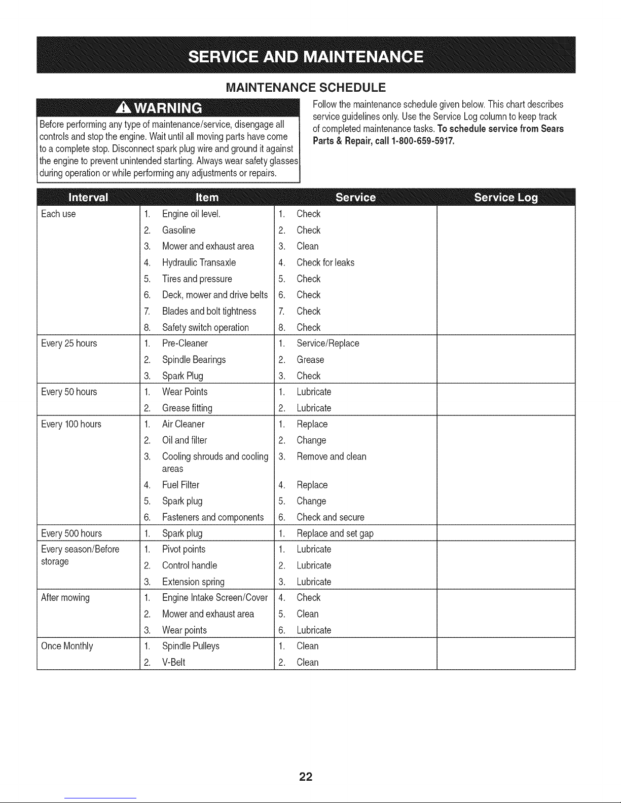
MAINTENANCE SCHEDULE
Beforeperforminganytypeof maintenance/service,disengageall
controlsandstopthe engine.Waituntilall movingpartshavecome
toacompletestop.Disconnectsparkplugwireand grounditagainst
theengineto preventunintendedstarting.Alwayswearsafetyglasses
duringoperationorwhile performingany adjustmentsor repairs.
Followthemaintenanceschedulegivenbelow.Thischartdescribes
serviceguidelinesonly.UsetheServiceLogcolumnto keeptrack
ofcompletedmaintenancetasks.To schedule service from Sears
Parts& Repair,call 1-800-659-5917.
Eachuse
Every25 hours
Every50 hours
Every100hours
Every500 hours
Everyseason/Before
storage
Aftermowing
OnceMonthly
1. Engineoillevel.
2. Gasoline
3. Mowerand exhaustarea
4. HydraulicTransaxle
5. Tiresand pressure
6. Deck,moweranddrivebelts
7. Bladesandbolttightness
8. Safetyswitchoperation
1. Pre-Cleaner
2. SpindleBearings
3. SparkPlug
1. WearPoints
2. Greasefitting
1. AirCleaner
2. Oilandfilter
3. Coolingshroudsandcooling
areas
4. FuelFilter
5. Sparkplug
6. Fastenersand components
1. Sparkplug
1. Pivotpoints
2. Controlhandle
3. Extensionspring
1. EngineIntakeScreen/Cover
2. Mowerand exhaustarea
3. Wearpoints
1. SpindlePulleys
2. V-Belt
1. Check
2. Check
3. Clean
4. Checkfor leaks
5. Check
6. Check
7. Check
8. Check
1. Service/Replace
2. Grease
3. Check
1. Lubricate
2. Lubricate
1. Replace
2. Change
3. Removeandclean
4. Replace
5. Change
6. Checkandsecure
1. Replaceandsetgap
1. Lubricate
2. Lubricate
3. Lubricate
4. Check
5. Clean
6. Lubricate
1. Clean
2. Clean
22
Page 23

Beforeperforminganymaintenanceor repairs,disengagethe PTO,
movethedrivecontrolleversfullyoutwardintheneutralposition,
engagetheparkingbrake,stoptheengineand removethekeyto
preventunintendedstarting.
ENGINE MAINTENANCE
Thoroughlywashyourhandswithsoapandwaterassoonas
possibleafterhandlingusedoil.
Check Engine Oil
1. Checkoilbeforeeachuse.Stopengineandwaitseveralminutes
beforecheckingoil level.Withengineon levelground,theoil must
beto FULLmarkon dipstick.
2. Refertothe Assemblysectionofthismanualforinstructionson
checkingtheoil.
Change Engine Oil and Filter
• Refertothe viscositychart(Figure22)foroil recommenda-
tions.Do notoverfill.SAE30 isrecommendedfor general,all
temperatureuse.Usea 4-stroke,or anequivalenthighdetergent,
premiumqualitymotoroilcertifiedtomeetor exceedU.S.
automobilemanufacturer'srequirementsfor serviceclassification
SF,SG,SH,SJ or higher.MotoroilsclassifiedSF,SG,SH,SJ will
showthisdesignationon thecontainer.
4O
a6 .
50
_4
°22
iU L:F ¸3o
i...................................................................20
C
C
>
10
_20
0
-30
Draining the Oil
1. Runthe enginefor a shorttimetowarmthe engineoil.The oil
willflowmorefreelyandcarryawaymoreimpurities.Usecareto
avoidburnsfromhotoil.
2. Locatetheoildrainvalveontheleftsideoftheengine.SeeFigure23.
Figure23
3. Popopentheprotectivecapon theendof theoildrainvalveto
exposethedrainport.Referto Figure23.Removetheoilfill cap/
dipstickfromtheoil fill tube.
4. Pushtheoildrainhose(packedwiththismanual)ontotheoildrain
port.Routetheoppositeendd thehoseintoanappropriateoilcollec-
tioncontainerwithatleasta2.5quartcapacity,to collecttheusedoil.
5. Turntheoildrainvalve1/4-turn,thenpulloutwardtobegindraining
oil.Aftertheoil hasfinisheddraining,pushtheendoftheoildrain
valvebackin andturn1/4-turntosecureitbackinplace.Re-capthe
endoftheoildrainvalvetokeepdebrisfromenteringthedrainport.
6. Cleantheareaaroundtheoil filter.Placeacontainerunderthe
filtertocatchanyoiland removethefilter.See Figure24.
-- Below 40 ° F (4 ° C) the use of SAE 30W will result in hard starting.
** -- Above 80 ° F (27 ° C) the use of 10W-30 may cause increased oil consumption,
Check the oil level more frequently,
Figure22
NOTE:DOnotusenon-detergentoil or2-strokeengineoil. it could
shortentheenginesservicelife.
o Changeengineoilafterthefirstfivetoeighthoursofoperation,
andeveryfifty hoursoreveryseasonthereafter.Changeoilevery
twentyfivehourswhenoperatingengineunderheavyloadorin
hightemperatures.
23 Figure24
Page 24
7. Placethe newfilterinan openpanwiththe opensidefacingup.
Fillwith newoil untilthe oil reachedthebottomofthe threads.
Waittwo minutesfortheoil to beabsorbedbythefiltermaterial.
8. Applya thinfilmof cleanoiltothe rubbergasketonthefilter.
9. Carefullyinstallthenewfilter.
10. Refilltheenginewiththerecommendedoil andchecktheoil
level;referto CheckingandAddingOilin theAssemblySection.
11.
Reinstalltheoilfillercap/dipsticksecurely.
12.
Reconnectsparkplugwire.
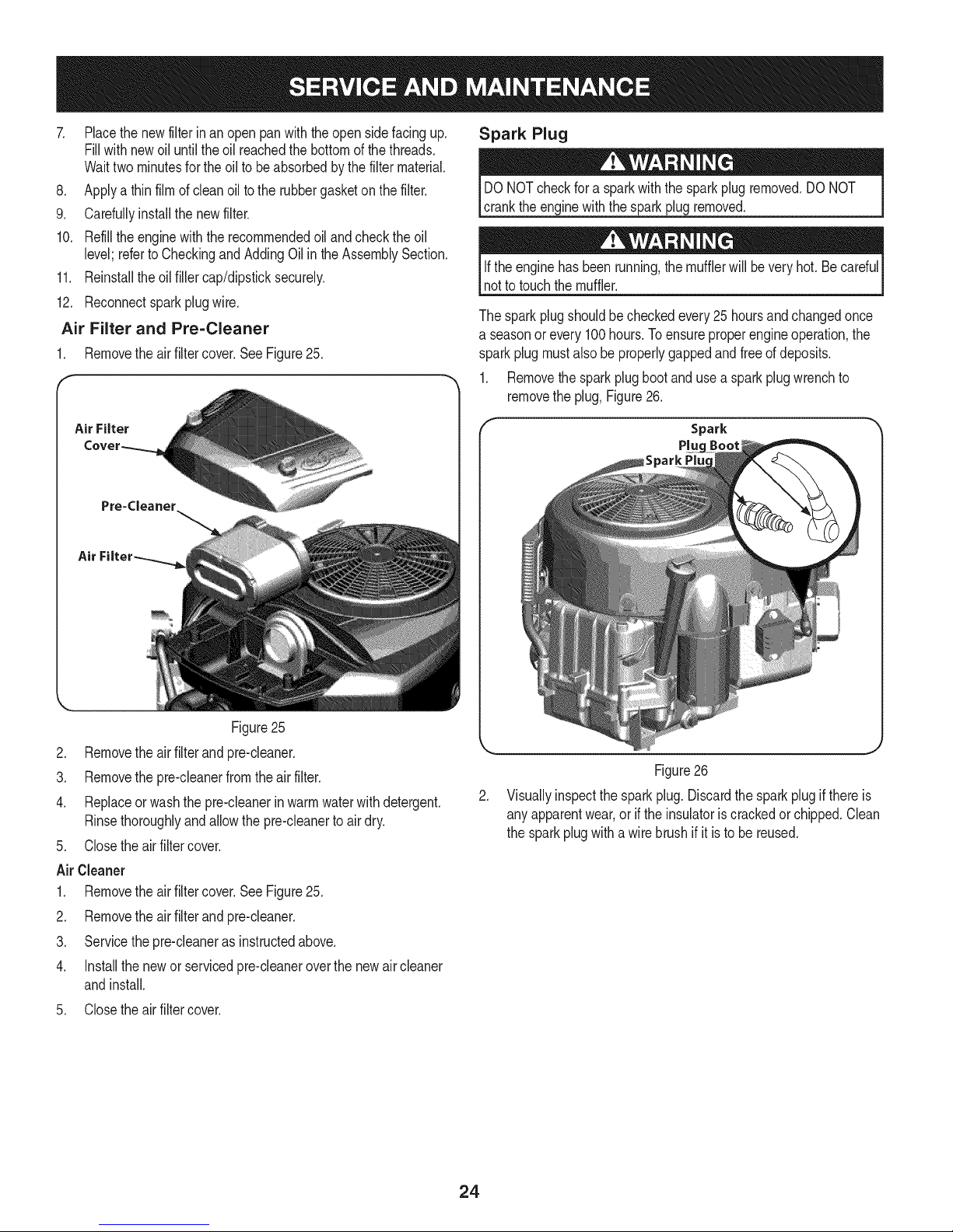
Air Filter and Pre=Cleaner
1. Removetheair filtercover.SeeFigure25.
Spark Plug
DONOTcheckfora sparkwiththe sparkplugremoved.DONOT
cranktheenginewiththe sparkplugremoved.
Iftheenginehas beenrunning,themufflerwillbeveryhot. Becardul
notto touchthemuffler.
Thesparkplugshouldbecheckedevery25hoursandchangedonce
a seasonor every100hours.Toensureproperengineoperation,the
sparkplugmustalsobe properlygappedandfreeofdeposits.
1. Removethesparkplugboot andusea sparkplugwrenchto
removethe plug,Figure26.
Air Filter
Pre=Cleaner
Air
Figure25
2. Removetheair filterand pre-cleaner.
3. Removethe pre-cleanerfromthe air filter.
4. Replaceor washthe pre-cleanerinwarmwaterwithdetergent.
Rinsethoroughlyandallowthepre-cleanerto air dry.
5. Closetheairfiltercover.
AirCleaner
1. Removetheair filtercover.SeeFigure25.
2. Removetheair filterand pre-cleaner.
3. Servicethepre-cleaneras instructedabove.
4. Installthe newor servicedpre-cleaneroverthe newair cleaner
andinstall.
5. Closetheairfiltercover.
Spark
Pluc
Figure26
2. Visuallyinspectthe sparkplug.Discardthesparkplugifthereis
anyapparentwear,or if theinsulatoris crackedorchipped.Clean
thesparkplugwitha wire brushif it is tobe reused.
24
Page 25
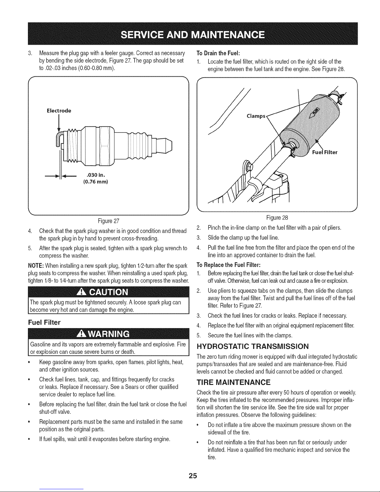
3. Measurethe pluggapwitha feelergauge.Correctas necessary To Drain the Fuel:
bybendingthesideelectrode,Figure27.Thegapshouldbeset 1. Locatethe fuelfilter,whichis routedontheright sideof the
to.02-.03inches(0.60-0.80ram). enginebetweenthe fueltankandthe engine.SeeFigure28.
Electrode
Clamps_
.030 in.
(0.76ram)
Figure27
4. Checkthatthe sparkplugwasherisingoodconditionandthread
thesparkplugin by handtopreventcross-threading.
5. Afterthesparkplugis seated,tightenwitha sparkplugwrenchto
compressthe washer.
NOTE:Wheninstallinga newsparkplug,tighten1/2-turnafterthespark
plugseatstocompressthewasher.Whenreinstallinga usedsparkplug,
tighten1/8-to1/4-turnafterthe sparkplugseatstocompressthewasher.
Thesparkplugmustbetightenedsecurely.A loosesparkplugcan
becomevery hotandcandamagetheengine.
Fuel Filter
Gasolineanditsvaporsareextremelyflammableandexplosive.Fire
or explosioncan causesevereburnsor death.
• Keepgasolineawayfromsparks,openflames,pilotlights,heat,
andotherignitionsources.
• Checkfuellines,tank,cap,andfittingsfrequentlyforcracks
orleaks.Replaceif necessary.SeeaSearsorotherqualified
servicedealerto replacefuelline.
• Beforereplacingthe fuelfilter,drainthefueltankor closethefuel
shut-offvalve.
• Replacementpartsmustbethesameandinstalledinthesame
positionasthe originalparts.
• If fuelspills,waituntilit evaporatesbeforestartingengine.
Figure28
2. Pinchthein-lineclamponthefuel filterwitha pairof pliers.
3. Slidetheclampup thefuelline.
4. Pullthefuel linefreefromthe filterandplacetheopenendofthe
lineintoanapprovedcontainerto drainthefuel.
To Replacethe FuelFilter:
1. Beforereplacingthefuelfilter,drainthefueltankorclosethefuelshut-
offvalve.Otherwise,fuelcanleakoutandcauseafireorexplosion.
2. Usepliersto squeezetabson theclamps,thenslidethe clamps
awayfromthefuelfilter.Twistandpullthe fuellinesoffof thefuel
filter.Referto Figure27.
3. Checkthefuellinesforcracksorleaks.Replaceifnecessary.
4. Replacethefuelfilterwithanoriginalequipmentreplacementfilter.
5. Securethefuellineswiththeclamps.
HYDROSTATIC TRANSMISSION
Thezeroturnridingmoweris equippedwithdualintegratedhydrostatic
pumps/transaxlesthatare sealedandare maintenance-free.Fluid
levelscannotbecheckedandfluidcannotbeaddedorchanged.
TIRE MAINTENANCE
Checkthetireairpressureafterevery50 hoursofoperationorweekly.
Keepthetires inflatedtotherecommendedpressures.Improperinfla-
tionwill shortenthetireservicelife.Seethe tiresidewallfor proper
inflationpressures.Observethefollowingguidelines:
• Donotinflatea tireabovethemaximumpressureshownon the
sidewallof thetire.
• Donotreinflatea tirethathas beenrunflator seriouslyunder
inflated.Haveaqualifiedtiremechanicinspectandservicethe
tire.
25
Page 26

LUBRiCATiON
Usinga pressurelubricatinggun, lubricatethefrontcastorwheel
axlesandthefrontpivotaxlewith No.2 multipurposelithium
greaseafterevery10hoursof service.
Periodicallylubricateallotherpivotpointswitha qualitylubricat-
ingoil.
GENERAL BATTERY iNFORMATiON
Shouldbatteryacidaccidentallysplatterintotheeyesor ontothe
skin,rinsetheaffectedareaimmediatelywithcleancold water.If
thereis anyfurtherdiscomfort,seekpromptmedicalattention.Ifacid
spillsonclothing,firstdiluteit withcleanwater,thenneutralizewitha
solutionofammonia/wateror bakingsoda/water.
NEVERconnect(ordisconnect)batterychargerclipstothebatterywhile
thechargeris turnedon,asitcancausesparks.Keepallsourcesofignition
(cigarettes,matches,lighters)awayfromthebattery.Thegasgenerated
duringchargingcanbecombustible.Asafurtherprecaution,onlycharge
thebatteryina wellventilatedarea.Alwaysshieldeyesandprotectskin
_andcothngwhenworkngnearbatteres.
BATTERY REMOVAL
leadcompounds.Washhandsafterhandling.
Thebatteryislocatedonthe right/rearofthe ridingmowerbeneaththe
seatboxframe.Toremovethebattery:
1. Removethetwohextappingscrewsfromthebatteryhold-down
bracketandremovethebracket.Usecareto avoidlosingthetrim
stripfromthebottomof thebracket.SeeFigure29.
f
Battery Hold Down Bracket
Hex Tap Screw
Batteriescontainsulfuricacidandmayemitexplosivegases.Useextreme
cautionwhenhandlingbatteries.Keepbatteriesoutofthereachofchildren.
Battery Maintenance
Thebatteryisfilled withbatteryacidandthensealedatthefactory.
However,evena "maintenancefree"batteryrequiressomemainte-
nanceto ensureitsproperlife cycle.
Spraytheterminalsandexposedwirewitha batteryterminalsealer,
orcoattheterminalswitha thincoatof greaseorpetroleumjelly,to
protectagainstcorrosion.
Alwayskeepthebatterycablesandterminalscleanandfreeof
corrosion.
Avoidtipping.Evena sealedbatterywillleak electrolytewhentipped.
Hex Cap Screw"
Figure29
2. Removethehexcapscrewandseresnutsecuringtheblack
negativebatteryleadto thenegativebatterypost(markedMEG).
Movethecable awayfromthenegativebatterypost.
3. Removethehexcapscrewandseresnutsecuringtheredposi-
tive batteryleadto thepositivebatterypost(markedPOS).
4. Carefullyliftthe batteryoutofthe ridingmower.
5. Installthebatteryby repeatingtheabovestepsinthe reverse
order.
Alwaysconnectthepositiveleadtothe batterybeforeconnectingthe
negativelead.Thiswillpreventsparkingor possibleinjuryfroman
electricalshortcausedbycontactingthe ridingmowerbodywithtoolsI
Ibengusedtoconnectthecabes. j
26
Page 27

Charging the Battery
1. Testand,ifnecessary,rechargethebatteryaftertheriding
mowerhasbeenstoredfor a periodoftime.
2. A voltmeterorloadtestershouldread12.6volts(DC)or higher
acrossthebatteryterminals.SeeFigure30.
Voltmeter Stateof Charging
Reading Charge Time
12.7 100% FullCharge
12.4 75% 90 Min.
12.2 50% 180 Min.
12.0 25% 280 Min.
Figure30
3. Chargethebatterywitha 12-voltbatterychargerataMAXIMUM
rateof 10amps.
SERViCiNG ELECTRICAL SYSTEM
A fuseisinstalledto protecttheridingmower'selectricalsystemfrom
damagecausedbyexcessiveamperage.Alwaysusethe samecapac-
ityfusefor replacement.Ifthe electricalsystemdoes notfunction,
checkfor a blownfuse.
If youhavea recurringproblemwithblownfuses,call1-800-659-5917
toschedule electricalsystemservicefromSearsParts& Repair.
RELAYS AND SWITCHES
Thereareseveralsafetyswitchesintheelectricalsystem.Ifa function
ofthe safetyinterlocksystemdescribedearlieris notfunctioning
properly,call 1-800-659-5917to havetheelectricalsystemcheckedby
SearsParts& Repair.
USING THE DECK WASH SYSTEM
Whenusingthedeckwashsystem,neverengagethedeckfromany
positionotherthantheoperator'sseatof theridingmower.Donot
usean assistantorengagedeckin thepresenceofanybystanders.
Pullbackthelockcollarofthe nozzleadapterandpushthe
adapterontothedeckwashnozzleat theleftendofthemower
deck.Releasethelockcollarto locktheadapteron thenozzle.
Referto Figure31.
Deck Wash
Nozzle
Figure31
4. Turnonthe watersupply.
5. Fromthe ridingmoweroperator'sseat,starttheengineand
engagethePTO.Allowto runas needed.Disengagethe PTO
and stoptheengine.
6. Turnoffthe watersupply.
7. Pullbackthelockcollarofthenozzleadaptertodisconnectthe
adapterfromthe nozzle.
CLEANING THE SPINDLE PULLEYS
Oncea monthremovethebeltcoverstoremoveanyaccumulationof
grassclippingsfromaroundthe spindlepulleysandV-belt.Cleanmore
oftenwhenmowingtall,dry grass.
Attachthe nozzleadaptertoa standardgardenhoseconnected
toa watersupply.
,
Movetheridingmowertoan areawithinreachof thehosewhere
thedispersalofwetgrassclippingsisnotobjectionableto you.
Disengagethe PTO,engagethe parkingbrake,andstopthe
engine.
27
Page 28
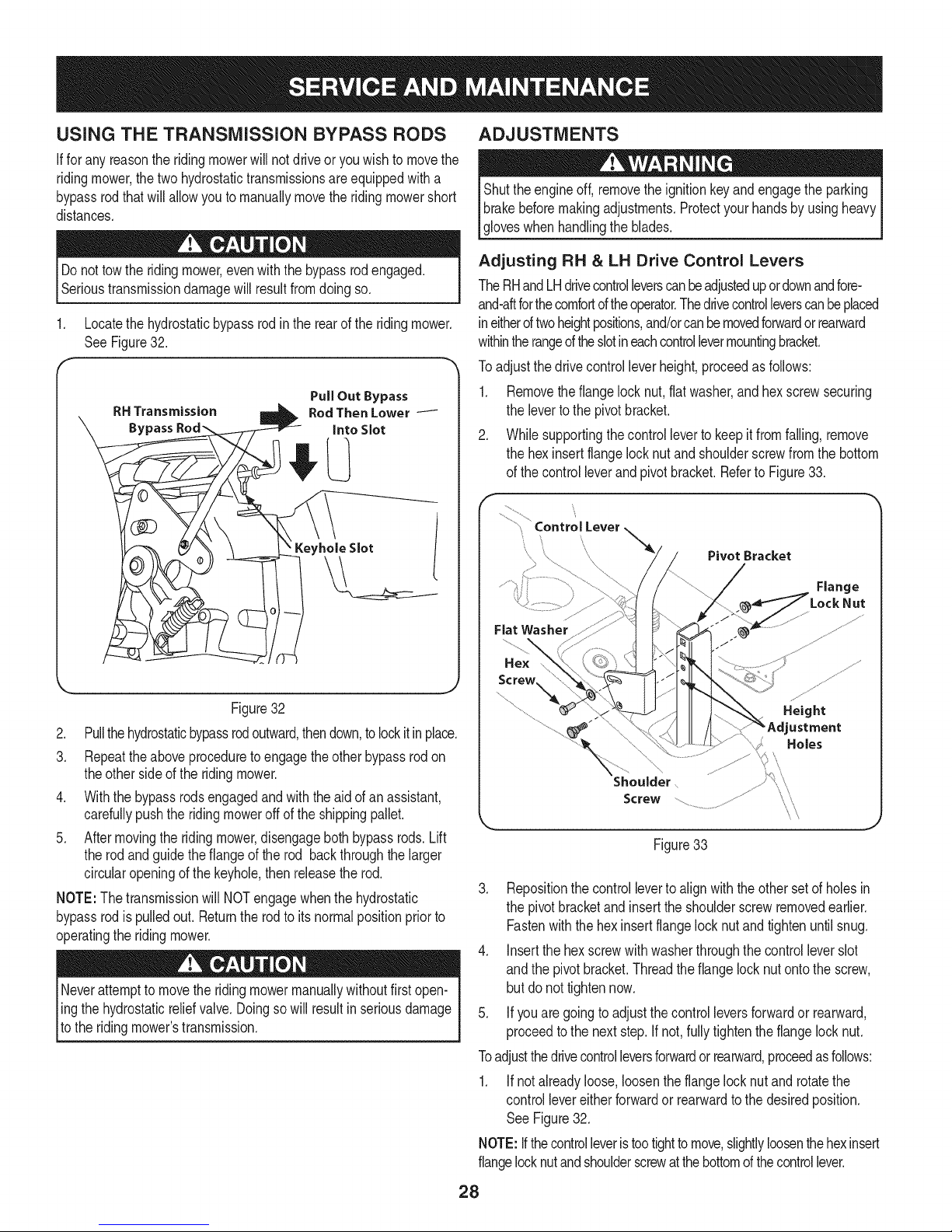
USING THE TRANSMiSSiON BYPASS RODS
Ifforany reasonthe ridingmowerwillnot driveor youwishtomovethe
ridingmower,thetwohydrostatictransmissionsareequippedwitha
bypassrodthatwill allowyou tomanuallymovetheridingmowershort
distances.
ADJUSTMENTS
Shuttheengineoff,removethe ignitionkeyandengagetheparking
brakebeforemakingadjustments.ProtectyourhandsbyusingheavyI
lg oveswhenhand ngthe bades. j
Donottowthe ridingmower,evenwiththebypassrodengaged.
Serioustransmissiondamagewillresultfromdoingso.
1. Locatethehydrostaticbypassrodintherearoftheridingmower.
SeeFigure32.
RH Transmission
Bypass
Figure32
2. Pullthehydrostaticbypassrodoutward,thendown,to lockitinplace.
3. Repeattheaboveproceduretoengagetheotherbypassrodon
theother sideof the ridingmower.
4. Withthe bypassrodsengagedandwiththeaidofanassistant,
carefullypushtheridingmoweroffof theshippingpallet.
5. Aftermovingthe ridingmower,disengagebothbypassrods.Lift
therodandguidethe flangeof therod backthroughthe larger
circularopeningof thekeyhole,then releasetherod.
NOTE:The transmissionwillNOTengagewhenthehydrostatic
bypassrodispulledout. Returnthe rodto itsnormalpositionpriorto
operatingthe ridingmower.
Neverattemptto movetheridingmowermanuallywithoutfirstopen-
ling thehydrostaticr,elief valve.Doingsowill resultinseriousdamage
[to theridingmowers transmission.
PullOut Bypass
RodThenLower
intoSlot
Keyhole Slot
Adjusting RH & LH Drive Control Levers
TheRHandLHdrivecontrolleverscanbeadjustedupordownandfore-
and-aftforthecomfortoftheoperator.Thedrivecontrolleverscanbeplaced
ineitheroftwoheightpositions,and/orcanbemovedforwardorrearward
withintherangeoftheslotineachcontrollevermountingbracket.
Toadjustthedrivecontrolleverheight,proceedasfollows:
1. Removetheflangelocknut,flatwasher,andhexscrewsecuring
thelevertothe pivotbracket.
2. Whilesupportingthecontrolleverto keepitfromfalling,remove
thehex insertflangelocknut andshoulderscrewfromthe bottom
ofthe controlleverandpivotbracket.Referto Figure33.
f
\
Fiat Washer
Hex
Shoulder
Screw
Figure33
3. Repositionthecontrolleverto alignwith theothersetofholesin
thepivotbracketandinserttheshoulderscrewremovedearlier.
Fastenwiththe hexinsertflangelock nutandtightenuntilsnug.
4. Insertthehexscrewwithwasherthroughthecontrolleverslot
andthepivotbracket.Threadtheflangelocknutontothescrew,
butdo nottightennow.
5. Ifyouaregoingto adjustthecontrolleversforwardorrearward,
proceedtothe nextstep.Ifnot,fullytightentheflangelocknut.
Toadjustthedrivecontrolleversforwardor rearward,proceedasfollows:
1. Ifnotalreadyloose,loosentheflangelocknutandrotatethe
controllevereitherforwardor rearwardtothedesiredposition.
See Figure32.
NOTE:Ifthecontrolleveristootightto move,slightlyloosenthehexinsert
flangelocknutandshoulderscrewatthebottomofthecontrollever.
PivotBracket 1
%2:°' J
28
Page 29
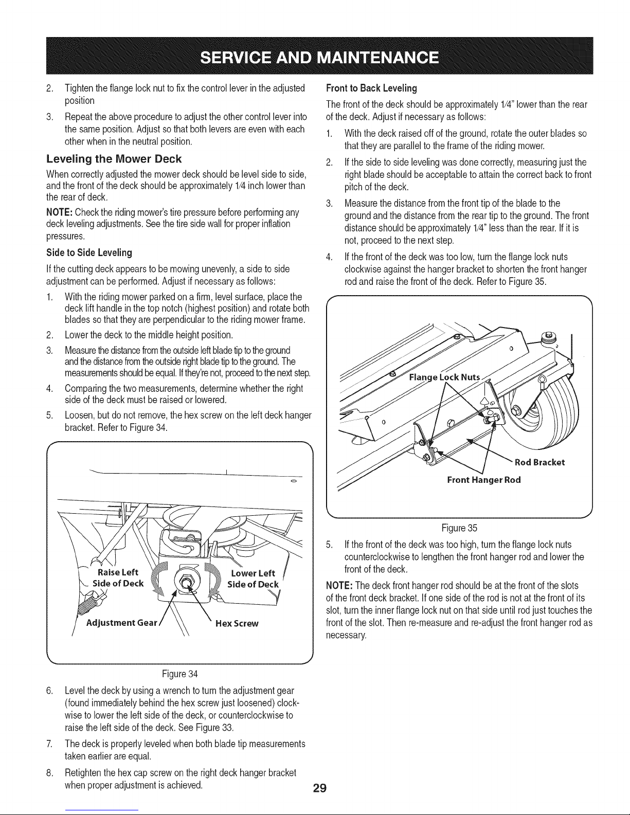
2. Tightentheflange locknutto fix thecontrolleverintheadjusted
position
3. Repeattheaboveprocedureto adjustthe othercontrolleverinto
thesameposition.Adjustsothat bothleversareevenwitheach
otherwheninthe neutralposition.
Leveling the Mower Deck
Whencorrectlyadjustedthemowerdeck shouldbelevelsidetoside,
andthefrontof thedeckshouldbeapproximately1/4inchlowerthan
therearof deck.
NOTE:Checktheridingmower'stirepressurebeforeperformingany
decklevelingadjustments.Seethetiresidewallfor properinflation
pressures.
Side to Side Leveling
If thecuttingdeckappearsto bemowingunevenly,a sideto side
adjustmentcan be performed.Adjustif necessaryasfollows:
.
Withtheridingmowerparkedon a firm,levelsurface,placethe
decklift handleinthetop notch(highestposition)androtateboth
bladessothattheyare perpendiculartothe ridingmowerframe.
.
Lowerthedecktothe middleheightposition.
3.
MeasurethedistancefromtheoutsideIdtbladetiptotheground
andthedistancefromtheoutsiderightbladetipto theground.The
measurementsshouldbeequal.Ifthey'renot,proceedtothenextstep.
.
Comparingthetwo measurements,determinewhethertheright
sideof thedeckmust beraisedorlowered.
5. Loosen,butdo not remove,thehexscrewonthe leftdeckhanger
bracket.RefertoFigure34.
Front to Back Leveling
Thefrontof thedeck shouldbeapproximately1/4"lowerthanthe rear
ofthe deck.Adjustifnecessaryas follows:
1. Withthedeckraisedoffoftheground,rotatetheouterbladesso
thattheyareparalleltothe frameofthe ridingmower.
2. Ifthesideto sidelevelingwasdonecorrectly,measuringjust the
rightbladeshouldbeacceptabletoattainthecorrectbacktofront
pitchofthe deck.
3. Measurethedistancefromthefronttip ofthe bladeto the
groundandthedistancefromthereartip tothe ground.Thefront
distanceshouldbe approximately1/4"lessthantherear.If itis
not,proceedtothenextstep.
4. Ifthefrontof thedeckwastoo low,turnthe flangelocknuts
clockwiseagainstthehangerbracketto shortenthe fronthanger
rodand raisethefrontofthe deck.Referto Figure35.
f
J
<=,
J
Figure34
6. Levelthedeckbyusingawrenchtoturntheadjustmentgear
(foundimmediatelybehindthehex screwjustloosened)clock-
wisetolowertheleft sideofthe deck,or counterclockwiseto
raisethe leftsideof thedeck.SeeFigure33.
7. Thedeckis properlyleveledwhenbothbladetip measurements
takenearlierareequal.
8. Retightenthehex capscrewonthe rightdeckhangerbracket
whenproperadjustmentisachieved.
Bracket
Front Hanger Rod
Figure35
Ifthefrontof thedeckwastoo high,turn theflangelock nuts
counterclockwisetolengthenthefronthangerrodandlowerthe
frontofthe deck.
NOTE:Thedeckfronthangerrodshouldbeatthefrontoftheslots
ofthe frontdeckbracket.Ifonesideof therodis notat thefrontof its
slot,turntheinnerflange locknuton thatside untilrodjust touchesthe
frontofthe slot.Then re-measureand re-adjustthefronthangerrodas
necessary.
29
Page 30
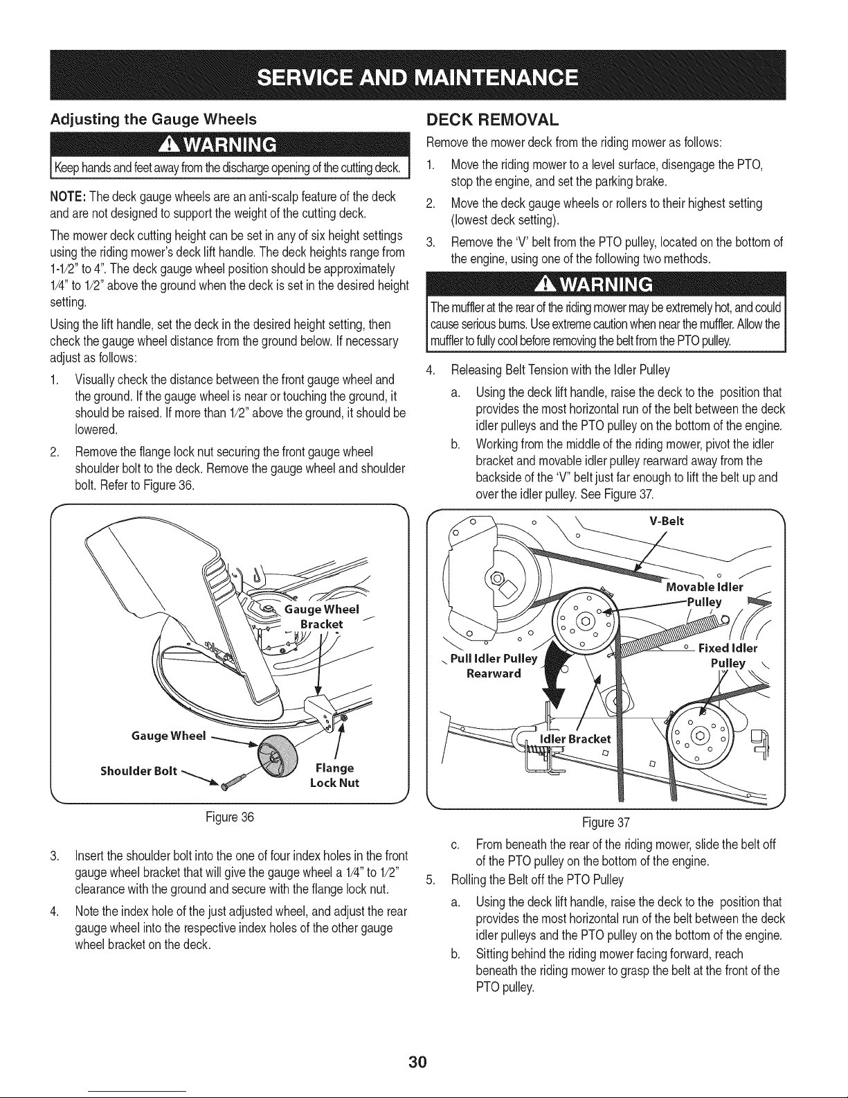
Adjusting the Gauge Wheels
Keephandsandfeetawayfromthedischargeopeningd thecuttingdeck.
NOTE:The deckgaugewheelsareananti-scalpfeatureofthedeck
andarenotdesignedtosupporttheweightofthecuttingdeck.
Themowerdeckcuttingheightcan besetinanyof six heightsettings
usingthe ridingmower'sdecklifthandle.Thedeckheightsrangefrom
1-1/2"to4".Thedeckgaugewheelpositionshouldbe approximately
1/4"to 1/2"abovethegroundwhenthedeckisset inthedesiredheight
setting.
Usingthelift handle,setthedeckinthe desiredheightsetting,then
checkthegaugewheeldistancefromthegroundbelow.Ifnecessary
adjustasfollows:
1. Visuallycheckthedistancebetweenthe frontgaugewheeland
theground.Ifthegaugewheelisnearortouchingtheground,it
shouldberaised.Ifmorethan1/2"abovetheground,itshouldbe
lowered.
.
Removetheflangelocknutsecuringthefrontgaugewheel
shoulderboltto thedeck.Removethe gaugewheelandshoulder
bolt.Referto Figure36.
DECK REMOVAL
Removethemowerdeckfromthe ridingmoweras follows:
1. Movetheridingmowerto a levelsurface,disengagethe PTO,
stoptheengine,andsetthe parkingbrake.
2. Movethedeckgaugewheelsor rollerstotheir highestsetting
(lowestdecksetting).
3. Removethe'V' beltfromthePTOpulley,locatedonthe bottomof
theengine,usingoneof thefollowingtwomethods.
Themufflerattherearoftheridingmowermaybeextremelyhot,andcould
causeseriousbums.Useextremecautionwhennearthemuffler.AllowtheI
Imuffertofuy coobeforeremovngthebetfromthePTOpu ey. j
.
ReleasingBeltTensionwiththe IdlerPulley
a. Usingthedeck lifthandle,raisethedecktothe positionthat
providesthemosthorizontalrunof thebelt betweenthe deck
idlerpulleysandthe PTOpulleyonthebottomoftheengine.
b. Workingfromthemiddleofthe ridingmower,pivottheidler
bracketandmovableidlerpulleyrearwardawayfromthe
backsideofthe'V" beltjustfar enoughto liftthe beltupand
overthe idlerpulley.SeeFigure37.
V=Belt
Gauge Wheel
Bracket
Gauge Wheel
Shoulder Bolt
Flange
Lock Nut
Figure36
3. Insertthe shoulderboltintothe oneoffourindexholesin the front
gaugewheelbracketthatwillgivethegaugewheela 1/4"to 1/2"
clearancewiththe groundandsecurewiththeflangelocknut.
4. Notetheindexholeofthejustadjustedwheel,andadjusttherear
gaugewheelintothe respectiveindexholesofthe othergauge
wheelbracketonthedeck.
Figure37
c. Frombeneaththe rearofthe ridingmower,slidethebeltoff
ofthe PTOpulleyonthebottomofthe engine.
.
RollingtheBeltoff the PTOPulley
a. Usingthedeck lifthandle,raisethedecktothe positionthat
providesthemosthorizontalrunof thebelt betweenthe deck
idlerpulleysandthe PTOpulleyonthebottomoftheengine.
b. Sittingbehindtheridingmowerfacingforward,reach
beneaththe ridingmowerto graspthe beltat thefrontof the
PTOpulley.
30
Page 31

Usecautiontoavoidpinchingyourfingerswhenrollingthebeltoffthe
PTOpulley.
c. Pullthe leftsideof the beltrearwardanddownwardwhile
manuallyturningthePTOpulleytotheright untilthe belt
ridesout ontothe edgeofthe lowersheaveofthepulley.
NOTE:Ifpullingthe rightsideofthe belt,turnthe pulleyto theleft.
d. Whilestillholdingthe beltdownward,continueturningthe
PTOpulleyuntilthe beltis rolledoff thepulley.Referto
Figure38.
f
PTO Belt
Transmission
Tube
\
Figure38
.
Lowerthedecktothe groundusingthe decklift handle.
6.
LocatetheLHand RHdeck supportpinsoneach sideof the
deck.Pullthe decksupportpinsoutwardandlockin the disen-
gagedpositionto releasethe deckfromtheridingmower'sLH
andRHdecklift arms.Referto Figure39.
f
7. Raisethedecklift armsoutofthe rearhangerbracketslotsby
raisingthedecklift handleon the ridingmowertoits highest
position.RefertoFigure37.
8. Slidethedeckforwardsothatthedeckfronthangerrodcan be
liftedoutof thetwoslotsofthe frontdeckbracket.Afterliftingthe
fronthangerrodoutof theslots,slidethedeck rearwardsothat
therodcan no longerengagethe slots.
9. Usingcareto preventthefronthangerrodfromfallingbackinto
thedeckbracketslots,carefullyslidethecuttingdeck(fromthe
rightside)outfromunderneaththe ridingmower.
DECK INSTALLATION
Toinstallthe mowerdeck, proceedasfollows:
1. Whileholdingthedeckfronthangerrodupward,carefullyslide
thedeckunderneaththe rightside ofthe ridingmower.
2. Whilestill holdingthefronthangerrod,slidethedeckforwarduntil
thefronthangerrodcan beloweredintotheslotsofthefrontdeck
bracket.
3. Lowerthefronthangerrodintothe slotsof thefrontdeckbracket,
thenslidethedeckrearward.
4. Maneuverthe decksothatthe slotsinthe two reardeckhanger
bracketsapproximatelyalignwiththedeckliftarmsof theriding
mower.Referto Figure39.
5. Usethe ridingmowerdecklift handletolowerthedeckliftarms
intothe slotsof thereardeckhangerbrackets.
6. Pullthedecksupportpins outwardand maneuverthedeckas
necessaryto aligntheholesin thedeckliftarmswiththe pins.
,,J
Referto Figure39.
7. Whenaligned,pusheachpinfullyinwardthroughtheliftarmsto
securethe armsinthe rearhangerbracketslots.
8. Makecertainthe'V' beltis inthespindlepulleysonthe deck;then
routethebeltrearwardbeneaththeridingmowerframe,abovethe
transmissiontube(s),tothePTOpulleyonthe bottomoftheengine.
9. Installthe'V' beltontothePTOpulleyusingoneofthefollowing
two methods.
-- Rear Deck Deck Lift Arm
Hanger Bracket
i
Deck
Support _\ Rear Hanger
Pin Bracket Slot
Figure39
Themuffleratthe rearofthe ridingmowermaybe extremelyhot,
andcouldcauseseriousburns.Useextremecautionwhennearthe
[muffer.A ow themuffertofu ycoo beforensta ngthebet.
10.
UsingtheIdlerPulleytoTensionthe Belt.
a. Usingthedecklifthandle,raisethedecktothe positionthat
providesthelongesthorizontalrund thebeltbetweenthedeck
idlerpulleysandthePTOpulleyonthebottomof theengine.
b. Installthebeltinthe PTOpulleyonthebottomoftheengine.
c. Routethebacksideofthebelt aroundthefixedidlerpulleyof
thedeck. Referto Figure37.
d. Workingfromthemiddleofthe ridingmower,pivottheidler
bracket/movablepulleyrearwardagainstthespringtension
and slidethe backsideofthe beltontothe movableidler
pulley.Referto Figure37.
31
Page 32

11.
Rollingthe BeltintothePTOPulley.
a. Usingthedecklifthandle,raisethedecktothe positionthat
providesthe longesthorizontalrunofthebeltbetweenthedeck
idlerpulleysandthe PTOpulleyonthe bottomoftheengine.
b. Makecertainthe beltisin the spindlepulleysofthedeck,
andthatthebacksideofthe beltis againstboththefixedand
movableidlerpulleys.Referto Figure35.
c. Sittingbehindthe ridingmower,facingforward,makecertain
thebelt isnottwisted;then reachbeneaththe ridingmower
tograspthebeltand pullittowardthe PTOpulley.
Usecautiontoavoidpinchingyourfingerswhenrollingthebeltoff the
PTOpulley.
d. Pulltherightsideofthe beltrearwardandplacethenarrow
V sideof thebelt intothe PTOpulley.SeeFigure37.
e. Whileholdingthe beltandpulleytogether,rotatethepulley
tothe left(SeeFigure36). Continueholdingand rotatingthe
pulleyandbeltuntilthe beltis fully rolledintothe PTOpulley.
REPLACING THE DECK DRIVE BELT
1. Removethedeckfrombeneaththeridingmower,(referto Deck
Removalon page30).
2. Removethehexwasherscrewssecuringthebeltcoverstothedeck
andremovethebeltfromthespindlepulleys.Referto Figure40.
Mower Blade Care
Beforeperforminganymaintenance,placethePTOswitchinthe"OFF"
position,engagetheparkingbrakelever,turntheignitionkeytothe
"OFF"positionandremovethe keyfromtheswitch.Protectyourhands
byusingheavygloveswhenhandlingthe blades.Whenservicingthe
mowerdeck,becarefulnotto cutyourselfonthesharpenedblades.
Thecuttingbladesmustbekeptsharpat alltimes.Sharpenthecutting
edgesof thebladesevenlysothatthe bladesremainbalancedandthe
sameangleof sharpnessis maintained.
Ifthecuttingedgeofa bladehas alreadybeensharpenedmanytimes,
or ifany metalseparationis present,it isrecommendedthatnew
bladesbe installed.NewbladesmaybeobtainedthroughSearsParts
& Repairorby calling1-800-659-5917.
Thebladesmaybe removedas follows.
1. Removethedeckfrombeneaththe ridingmower,(referto Deck
Removalon page30) thengentlyflip thedeckovertoexposeits
underside.
.
Usea 15/16"wrenchtoholdthehexnutontopofthespindle
assemblywhenlooseningthe hexnutsecuringtheblade.A block
ofwood maybe placedbetweenthedeckhousingandthecutting
edgeofthe bladeto helpinbreakingloosethe hexnutsecuring
theblade.SeeFigure41.
Hex
Washer_
Screw
Hex
Washer
Screw
Figure40
3. Installthe newbeltaroundthespindlepulleysas shownin Figure
40and reinstallthe beltcovers.
.
Routethebelt rearwardbetweenthetwoidlerpulleysandreinstall
thedeckfollowingthe instructionsin DeckInstallation.
WoodBlock/
//
He× Flang,
Spindle Assembly
Figure41
3. Whenreinstallingtheblades,besuretheyareinstalledso thatthe
windwingsarepointingupwardtowardthetop ofdeck.
4. Tightenthebladenutsto 70-90ft. Ibs.
5. Reinstallthedeck(refertoDeckInstallationonpage31).
32
Page 33

TRANSMiSSiON DRIVE BELT
Severalcomponentsmustberemovedandspecialtoolsusedin
ordertochangetheridingmower'stransmissiondrivebelt.Seeyour
SearsServiceCenterorto scheduleservice,simplycontactSearsat
1-800-4-MY-HOME®.
RIDING MOWER CREEPING
Creepingistheslightforwardor backwardmovementof theriding
mowerwhentheengineisrunningat highidleandthedrivecontrol
leversareopenedoutinthe neutralposition.
If afteroperatingtheridingmowerfor sometime,it beginsto creep
whilein the neutralposition,adjustthe transmissioncontrolrodsas
follows.
1. Placethefrontofthe ridingmoweragainstanimmovableobject
(e.g.wall,post,etc.).
2. Jackup the rearofthe ridingmowersothat bothrearwheelsare
approximatelyoneinch ofthe ground.
3. Withtheenginerunningat highidleandthedrivecontrol
leversopenedoutinthe neutralposition,andtheparkingbrake
disengaged,checkthe rearwheelsfor rotation.
4. If onlyonewheelis rotating,locatethetransmissioncontrolrod
beneaththeframeatthe frontofthe reartire. Ifbothwheels
rotate,locatebothcontrolrods.SeeFigure42.
RIDING MOWER HIGH SPEED TRACKING
1. Iftheridingmowertracksto onesidewith bothdrivecontrollevers
fullyforward,adjustthecontrolleversasfollows:
2. Checkforproperandbalancedairpressureinbothfrontand rear
tires.Refilltiresif necessary.
3. Performthefirstthreestepsin theprevioussub-section,Riding
mowerCreeping,toverifythatthe ridingmowerisnot creeping.If
creeping,adjustfollowingthe instructionsinthatsub-section.
4. Recheckthetrackingaftermakinganyadjustmentsto the
transmissioncontrolrods.
5. Ifuneventrackingpersists,notewhichdirectiontheridingmower
istracking.
6. Iftheridingmowertracksto theright,adjustthecontrolleverstop
boltonthe left side.
7. Ifthe ridingmowertracksto theleft,adjustthecontrolleverstop
boltonthe rightside.
8. Locatetheapplicablestopbolton the leftor rightconsole.See
Figure43.
RH Transmission
Flange
Lock Nut
Transmission
J
Arm
Figure42
5. Removetheflangelocknut andhexscrewsecuringthetransmis-
sioncontrolrodto thetransmissioncontrolarm.Wheelrotation
shouldstop.Ifit doesnot,callthe CraftsmanHelpLineat
1-800-659-5917.
.
If therotationstops,adjustthe controlrodupor downas
necessaryto alignwiththeholeinthe transmissioncontrolarm.
Re-insertthehexnut intothe holein thecontrolarmandsecure
withthehexlocknut.
7.
Ifnecessary,repeattheprevioustwostepstoadjusttheother
transmissioncontrolrod.
Console
Jam Nut
Bolt
Figure43
9. Loosenthejamnut onthestopbolt,thenturnthe stopbolt
counterclockwisetomakeit longer.Recheckthetrackingandfine
tunetheadjustmentas necessary.
NOTE:Ifthestopboltisadjustedtoofar,thetrackingproblemwillchange
sides.Makefinetuningadjustmentsbyshorteningthesamebolt.
10. Tightenthejam nutagainstthe consoleandrepositionthe control
leverasnecessaryto makethetwo controlhandlesevenwith
eachother.
8. Lowerthe ridingmowerand removethejack. 33
Page 34

Neverstoregardentractorwithfuel intankindoorsorin poorly
ventilatedareaswherefuelfumesmayreachan openflame,spark,
or pilotlightasona furnace,waterheater,clothesdryer,or gas
appliance.
TRACTOR STORAGE
If yourtractorisnotgoingtobe operatedfor an extendedperiodof
time(thirtydaysto approximatelysix months),thetractorshouldbe
preparedfor storage.Storethetractorin a dryandprotectedlocation.
If storedoutside,coverthetractor(includingthetires)to protectitfrom
theelements.Theproceduresoutlinedbelowshouldbeperformed
wheneverthetractoris placedinstorage.
1. Changetheengineoilandfilterfollowingtheinstructionsprovided
in theServiceand Maintenancesectionofthismanual..
Neverstorethetractorwithfuelinthe tankindoorsorin poorly
ventilatedenclosures,wherefuelfumesmayreachanopenflame,
sparkor pilotlight asona furnace,waterheater,clothesdryer,etc.
.
If storingthetractorfor30daysor more:
a. Topreventgumdepositsfromforminginsidetheengine's
carburetorandcausingpossiblemalfunctionof theengine,the
fuelsystemmustbeeithercompletelyemptied,orthe gasoline
mustbetreatedwitha stabilizertopreventdeterioration.
9roblems.
b. Usingafuel stabilizer:
• Readthe productmanufacturer'sinstructionsand recom-
mendations.
• Addtoclean,freshgasolinethecorrectamountof
stabilizerforthecapacity(approximately3 gallons)of the
fuelsystem.
• Fillthe fueltankwithtreatedfueland runtheenginefor
2-3minutestogetstabilizedfuel intothe carburetor.
c. Emptyingthefuel system:
• Priorto puttingthe tractorinstorage,monitorfuel
consumptionwiththe goalofrunningthefueltankempty.
• Starttheengineandallowitto runoutof fuel.Thiswill
preventgum andvarnishdepositsfromforming.
3. Removethesparkplugsandpourapproximatelyoneounceofoil
intoeachcylinder.Cranktheengineoneor twoturnstospread
theoilevenlyonthe cylinderwalls.Replacethe sparkplugs.
4. Cleantheengineand theentiretractorthoroughly.
NOTE:Useof a pressurewasheror gardenhoseisnot recommended
tocleanyourtractor.Theymaycausedamagetoelectricalcompo-
nents,spindles,pulleys,bearingsorthe engine.Theuseof waterwill
resultin shortenedlife andreduceserviceability.
5. Sharpenthebladessothatthe mowerwillbe readytouse when
needed.
6. Protectthemetalsurfaces.Repairscratcheswiththeappropriate
touch-upspraypaint.Brusha rustpreventiveoilonany unpainted
surfacesincludingthepulleysandblades.(Becarefulnot toget
anyoilon thedrivebelts.)
7. Cleanandfullychargethebattery,thendisconnectthe negative
cableat thebatterytopreventpossibledischarge.Rechargethe
batteryperiodicallywhenin storage.
NOTE:Removethebatteryifexposedto prolongedperiodsofsub-
freezingtemperatures.Storeina cool,dry locationwheretemperatures
areabovefreezing.
8. Lubricatealllubricationpoints.
9. Jackthe mowerup andstoreit onblocksto taketheweightoffof
thetires.
REMOVING THE TRACTOR FROM STORAGE
1. Checktheengineoil.
2. Fullychargethebattery,lowertractoroff blocks,andinflatethe
tirestothe recommendedpressure.
3. Removethesparkplugsandwipethemoff. Usingthestarter,
cranktheengineto pumpthe excessoil out ofthe sparkplug
holes.Replacethe sparkplugsandthe ignitionleads.
4. Ifdrainedbeforestoring,fillthe fueltankwithclean,fresh
gasoline.
5. Checkthelevelof theengineoil inthe crankcaseandthe
hydraulicreservoirtank.
6. Starttheengineandallowto idlefor a fewminutestoensure
engineisoperatingproperly.
7. Drivethetractorwithouta loadto makecertainall thetractor
systemsarefunctioningproperly.
34
Page 35

Beforeperforminganytypeofmaintenance/service,disengageall
controlsandstoptheengine.Waituntilallmovingpartshavecometo
acompletestop.Disconnectsparkplugwireandgrounditagainstthe
Ienginetopreventunintendedstarting.Alwayswearsafetyglassesduring
l operationorwhileperforminganyadjustmentsor repairs.
Thissectionaddressesminor serviceissues.Toscheduleserviceat a SearsParts& RepairCenter,callthe CraftsmanHelp Lineat
1-800-858-5817.
Enginefailstostart
Enginerunserratically
1. PTO/BladeEngageknobengaged.
2. Parkingbrakenotengaged.
3. Sparkplugwire disconnected.
4. Throttlecontrollevernotincorrect starting
position.
5. Fueltankempty,orstalefuel.
6. Blockedfuel lineorfuel filter.
7. Faultysparkplug.
8. Engineflooded.
9. Fuse(s)blown.
1. TractorrunningwithChokeactivated.
2. Sparkplugwire loose.
3. Blockedfuel lineor stalefuel.
4. Ventingas capplugged.
5. Wateror dirt in fuelsystem.
6. Dirtyair cleaner.
1. Placeknobindisengaged(OFF)position.
2. Engageparkingbrake.
3. Connectwireto sparkplug.
4. PlaceThrottleleverto FASTposition.
5. Filltankwithclean,fresh(lessthan 30daysold)gas.
6. Replacefuel line.Seea Searsorotherqualified
servicedealer.Replacefuelfilter.Seethe Service
andMaintenancesection.
7. Clean,adjustgapor replaceplug.
8. Crankenginewiththrottlein FASTposition.
9. Replacefuse.
1. Checkthatthe electricchokeis working.Seea
Searsorotherqualifiedservicedealer.
2. Connectandtightensparkplugwire.
3. Replacefuel line.Seea Searsorotherqualified
servicedealer.Filltankwithclean,freshgasoline
andreplacefuelfilter.Seethe Serviceand Mainte-
nancesection.
4. Clearventorreplacecapif damaged.
5. Drainfueltank.Refillwithclean,freshgasoline.See
the ServiceandMaintenancesection.
6. Cleanorreplaceair cleanerpaperelementorclean
foampre-cleaner.
NEED MORE HELP?
Find this and a[[ your other product manuals online.
Get answers from our team of home experts.
Get a personalized maintenance plan for your home.
Find information and toots to hetp with home projects.
• lili
b es_t _eyon by Sea_s
35
Page 36

Engineoverheats 1. Engineoillevellow
2. Air flowrestricted
2.
Enginehesitatesat highRPMs 1. Sparkpluggapsettooclose 1.
Engineidles poorly 1. Fouledsparkplug 1.
2. Dirtyair cleaner 2.
Excessivevibration 1. Cuttingbladeslooseor unbalanced 1.
2. Damaged,dull,or bentcuttingblade 2.
Unevencut 1. Decknot leveledproperly. 1.
2. Dullblade. 2.
3. Uneventire pressure. 3.
.
Fillenginewith properamountandtype of oil.
Cleangrassclippingsanddebrisfromaroundthe
engine'scoolingfinsandblowerhousing.
Removesparkplugandadjustgap.
Replacesparkplugandadjustgap.
Cleanor replaceair cleanerelementand/orclean
pre-cbaner.
Tightenbladeandspindle.Balanceblade.
Replaceblade.
Performside-to-sidedeckadjustment.
Sharpenor replaceblade.
Checktire pressureinallfourtires.
....... L
NEED MORE HELP?
Find this and a[[ your other product manuals online,
Get answers from our team of home experts.
Get a persona[ized maintenance plan for your home.
Find information and tools to help with home projects,
@ managemylife
_ (((((((((((((((((((((((((((S ((((((((((((((((((((((((
bI'_u_htte yes b_4Sea_
36
Page 37

Craftsman Zero=Turn Rider B IViodel No. 247.25001
11
5/
I = _ O
1 SeatBracket
703-08734-
0637
2 710-04482 HexFlangeBolt,3/8-16x,875
3 710-04484 HexWasherScrew,5/16-18x ,750
4 712-04063 FlangeLockNut,5/16-18
5 732-04849 CompressionSpring,1,50x3,90 x ,200
6 732-04563 CompressionSpring,,68x 1,065x .055
7 736-0258 FlatWasher,,385x 1,0x ,135
8 938-0296 ShoulderScrew,,437x .268x5/16-18
9 SeatMountBracket
783-06049-
0637
10 783-06050 SeatAdjustmentLever
11 783-06448 Clip
12 925-04040 SeatSwitch
13 757-04145 HighBackSeat
37
Page 38

Craftsman Zero=Turn Rider B Model No. 247.25001
2
3
4
5
6
7
935-0149
735-04081
951-04209B
751-10442
951-12428
751-12118
751-12089
FuelTankBushing
iRubberGrommet
FuelTank
FuelPick-UpFitting
iFuelCap
FuelRolloverValve
VentHose
38
Page 39

Craftsman Zero=Turn Rider- IViodel No. 247.25001
15..
20\
,\\\
18\
12
1 /
39
Page 40

Craftsman Zero=Turn Rider B Model No. 247.25001
1
2
3
4
5
6
7
8
9
10
11
12
13
14
15
16
17
18
19
20
21
22
23
603-04680A-
0637
703-05829
710-05097
710-3005
712-04065
732-0626
710-0520
738-04058
738-04162A
756-04129B
925-04847C
710-0653
712-0271
925-04022B
925-04165
925-04174
925-04228
725-04363
725-04439
925-2054A
925-1707D
738-04237A
726-0470
Frame Assembly
Drive Idler Arm
Hex Screw, 3/8-16x 1.5
Hex Screw, 3/8-16x 1.25
Flange Nut, 3/8-16
Extension Spring, .75 x 5.06
Hex Screw, 3/8-16x 1.5
Shoulder Spacer, .39 x 1.0 x .7
Shoulder Spacer, .884 x .19
Idler Pulley, 4.25 Dia.
Wire Harness
Hex Screw, 1/4-20x .375
Hex Nut, 1/4-20
Hour Meter
Neutral Switch
PTO Switch
Ignition Switch
Interlock Switch
Solenoid
Key
Battery
Shoulder Screw, #10-32 x .500
Cable Tie
4O
Page 41

Craftsman Zero=Turn Rider B Model No. 247.25001
18_<_
/
22
/
21
41
Page 42

Craftsman Zero=Turn Rider B Model No. 247.25001
603-04162 RHExhaustAssembly
2 603-04163 LH ExhaustAssembly
603-04691-
3 0637 FrameAssembly
4 703-05441A MufflerMountBracket
5 710-0227 HexWasherScrew,#8-18x 0.500
6 710-04683 HexWasherScrew,3/8-16x 1.000
7 710-0599 HexWasherScrew,1/4-20x0.500
8 710-1017 iABScrew,1/4-14x0.625
9 710-3008 HexScrew,5/16-18x .75
10 710-3217 MachineScrew,#8-32x 0.375
11 712-0142 iHexNut,#8-32
12 712-0271 iSemsNut,1/4-20
13 712-04063 iFlangeLockNut,5/16-18
14 721-0460 ExhaustGasket
15 726-0197 CableTie
16 726-0205 HoseClamp,.490
17 731-04914 ThrottleControlKnob
18 731-1999 ChokePlug
19 736-0148 LockWasher,3/8
20 746-04539 Throttle/ChokeControlCable
21 751-0616B DualNet Muffler
22 751-10349 iFuelHose,1/4
23 951-10517A iOil Drain
24 751-11053 iMufflerDeflector
25 751-3141-14 iOilDrainExtensionHose
26 756-04376 iPTOPulley
445677-0954-
27 G5 iReplacementEngine
42
Page 43

Craftsman Zero=Turn Rider B Model No. 247.25001
19
ii
//
\\
°\15
43
Page 44

Craftsman Zero=Turn Rider B Model No. 247.25001
603-04564 ConsoleMountBracket
2 SeatFrame
603-04946-
0637
3 735-04082C FootPad
4 703-05373B FootRest
5 736-0148 LockWasher,3/8
6 703-06451 ConsoleMountBracket
703-06623-
7 0637 FuelTankSupportBracket
8 710-04484 HexWasherScrew,5/16-18x .750
9 726-0201 SpeedNut,.3125
10 710-0604A iHexWasherScrew,5/16-18x .825
11 710-0778 HexWasherScrew,1/4-20x 1.500
12 710-0895 HexWasherScrew,1/4-15x .750
13 710-3008 HexScrew,5/16-18x .75
14 912-0298 iJamNut,1/4-20
15 712-04063 iFlangeLockNut,5/16-18
16 712-04092 iU-TypeNut,1/4-20
17 726-3046 RatchetClip,.250
18 731-06233 RHConsole
19 731-06263B LHConsole
20 710-0599 HexScrew,1/4-20x .5
703-05894-
21 0637 iBatteryHold-Down
22 731-0511 iTrimStrip
D = 0 0
44
Page 45

Craftsman Zero=Turn Rider B Model No. 247.25001
/
/
/ /
/ /
/
/
20/_"
17
2O
48
42
34
45
Page 46

Craftsman Zero=Turn Rider B IViodel No. 247.25001
D = 0 0
603-04160B-
1 0637 DeckLift ShaftAssembly
603-04322-
2 0637 LapbarLeverRH
603-04324-
3 0637 LapbarLeverLH
4 947-04065 BrakeRod(42"& 50" Decks)
5 647-04099A ControlShaft
6 703-05387B LapbarPivotBracket
7 BrakeHandle
703-05396A-
0637
703-05414A-
8 4044 FrontDeckHangerBracket
9 DeckLift Arm
703-05793A-
4044
10 703-06096A SwitchActuatorBracket
11 Lift LinkPlate
703-06169-
0637
12 710-0347 HexScrew,3/8-16x 1.75
13 710-0433 HexLockScrew,1/4-20x .62
14 710-3005 HexCapScrew,3/8-16x 1.25
15 710-3008 HexCapScrew,5/16-18x .75
16 710-3180 HexCapScrew,5/16-18x 1.75
17 911-0332 ClevisPin,.50x .78
18 712-04243 HexNut, 1/2-13
19 712-04063 HexFlangeinsertLockNut,5/16-18
20 712-04064 HexFlangeInsertLockNut,1/4-20
21 712-04065 HexFlangeinsertLockNut,3/8-16
22 712-0375 HexLockNut,3/8-16
23 912-3001 JamNut,3/8-24
24 714-04040 Bow-TieCotterPin
914-04023
26 716-0106
27 720-0311
28 723-04035
29 727-04141
30 731-04735
31 731-05732
32 720-0274
33 932-0334
34 732-0874
35 736-0270
36 936-0272
37 936-0275
38 732-04420
39 738-0143
40 938-0296
41 938-0507B
42 938-0572
43 938-0974
44 941-0225
45 741-3074
46 747-04401A
47 747-04637
48 747-05057
49 948-0227A
50 748-04169A
51 750-04676
52 750-04776
D = O O
CotterPin
E-Ring,.625 Dia.
HandleGrip
RodEnd
DamperCylinder
HandleGrip
Spacer,.62x 1.0
HandGrip
CompressionSpring
TorsionSpring
BellWasher,.265x .75x .062
FlatWasher,.51x 1.0x .06
FiatWasher,.344x .688x .065
TorsionSprg.,LH(50"&54" Decks)
ShoulderScrew,.498x .340x3/8-16
ShoulderScrew,.437x .268x5/16-18
ShoulderScrew,.5x .434x3/8-16
ShoulderScrew,.374x 1.16x 1/4-20
ShoulderScrew,.375x .38x 1/4-20
HexFlangeBearing
FlangeBearing,.626x .938x .344
DeckFrontHangerRod
DeckLiftHandleRod
LapbarControlRod
HexFlangeBearing
ControlHub
Spacer,.385x .630x .75
Spacer,.380x .625x .265
46
Page 47

Craftsman Zero=Turn Rider B IViodel No. 247.25001
47
Page 48

Craftsman Zero=TurnRiderB ModelNo.247.25001
918-04317
2 918-04431B
3 918-04432B
4
5 710-0176
6 710-0395
7 710-3119
8 712-04063
9 712-0459
10 712-3050
11 714-04040
12 936-0227
13 738-04192
14
15 750-04561
634-04293-
0961
747-04217C-
0637
16 954-04043A V-Belt
WheelHub,7/16-14x 1.6
TransmissionAssembly,LH
TransmissionAssembly,RH
WheelAssembly,18x 8.5-8
iHexCapScrew,5/16-18x2.75
iHexCapScrew,5/16-18x2.25
iHexCapScrew,3/8-16x .75
iHexFlangeNut,5/16-18
iHexFlangeNut,7/16-20
iLugNut,7/16-14
Bow-TieCotterPin
FlatWasher,.39x 1.5
iRod,.405x 14
BypassRod
iTube,.45x .69x 10.2
D = O O
48
Page 49

Craftsman Zero=Turn Rider B IViodel No. 247.25001
[]
31
49
``14
26
f
17
Page 50

Craftsman Zero=Turn Rider B Model No. 247.25001
903-04860-
1 4044 DeckHousing
2 918-04822A SpindleAssembly
3 631-04288 DischargeChuteAssembly
4 DeckLift Bracket
683-0254B-
4044
5 703-08336A PivotldlerBracket
6 710-04484 HexWasherHeadScrew,5/16-18x .750
7 710-0528 HexCapScrew,5/16-18x 1.25
8 710-0599 HexWasherHeadScrew,1/4-20x .5
9 710-3005 HexCapScrew,3/8-16x 1.25
10 710-3144 HexCapScrew,3/8-16x 2.00
11 710-3178 CarriageScrew,3/8-16x .75
12 710-3180 HexCapScrew,5/16-18x 1.75
13 712-0229 PushNut,3/8
14 712-04063 FlangeLockNut,5/16-18
15 712-04065 FlangeLockNut,3/8-16
16 712-0417A HexFlangeNut,5/8-18
17 912-0641 HexNut,M16-1.5
18 912-3010 HexNut,5/8-18
19 914-0470 CotterPin,1/8x 1.25
20 917-04074 DeckAdjustmentGear
21 732-0459C ExtensionSpring,.94Dia.x 6.74
22 732-04652 CompressionSpring,.535x 1.751
23 734-04155 DeckBallWheel,5.0
24 936-0119 LockWasher,5/16
25 936-0171 LockWasher,7/16
D = O
736-0225 internalToothLockWasher,5/8
i27 736-0262 FlatWasher,.385x .870x.092
i28 936-0344 FlatWasher,.385x 1.00x .030
i29 736-0277 FiatWasher,1.031x 1.620x .095
i30 738-04162A ShoulderSpacer,.884x.190
i31 938-3056 ShoulderScrew,.5x2.5x3/8-16
i32 942-04308 Blade,2in 1,21.23
i33 747-1116 DeckHangerRod
i34 954-04137A V-Belt
i35 756-04129B IdlerPulley,4.25 Dia.
783-06368A-
i36 4044 Bracket,Belt Guard
i37 783-06424A- BeltCover
4044
i38 936-0351 Washer,.760x 1.50x.030
i39 738-1186A SpindleShaft
i40 941-0919A BallBearing
i41 750-04936 Spacer,.792x 1.060x 1.860
i42 956-1227 DeckPulley
i43 737-04003D DeckWaterNozzle
i44 921-04041 WaterNozzleAdapter
i45 710-3157A Screw,7/16-20x 3.25
i46 917-04376A PTOElectricClutch
i47 711-04847B HingePin
i48 732-04372 TorsionSpring
i49 783-06074A ChuteBracket
5O
Page 51

Craftsman Zero=Turn Rider B IViodel No. 247.25001
f
603-04148C-
1 4044 FrontPivotAxle
2 i603-04308- CastorWheelBracket
4044
3 634-04746 WheelAssembly,11x4 x 5
4 710-04186 HexLockScrew,1/2-13x 1.25
5 710-0514 HexCapScrew,3/8-16x 1.0
6 911-04228 Axle Shaft
7 712-3022 HexLockNut, 1/2-13
9
10
11
12
13
14
15
731-05500
936-0169
936-0227
736-0250
937-3000
738-04182A
741-0516B
741-0990B
13
14/
D = _
FlangeBearing,1.0x 1.246
LockWasher,3/8
FlatWasher,.39x 1.5x .134
FlatWasher,1.0x 1.75x .107
LubeFitting,3/16
ShoulderScrew,7/16-14x .75x 4.75
iFlangeBearing,.76x 1.0x 1.2
iFlangeBearing,.76ID w/LubeFtg.
51
Page 52

Briggs & Stratton Engine IViodel 445677=0954=G5 For Zero=Turn Rider IViodel No. 247.25001
10 _ 850
250 _,
252
404 @ _\_
552A5_--i
742 d_ 616_
742 d_;_ i i
552A ¢_
552
691
750 f::_
d_-_
1027
1013
_ 524
_..........................................................J
239
4y
45
22
22o_._
52
Page 53

Briggs & Stratton Engine Model 445677-0954-G5 For Zero=Turn Rider Model No. 247.25001
' r
i25
26
332 ':-_-:_
75 %_::_
27 <>
27 _,_
24
146(_
" 50 [ 1777¸¸¸17777777777777771
_51
L
//
163 ::@/'- _4;
ff
51A 929 _
_J
JJ
53
741
< /
54_
186
1_::,t:
Page 54

Briggs & Stratton Engine IViodel 445677=0954-G5 For Zero=Turn Rider IViodel No. 247.25001
%
i
635
883
i
918 i
J1
1O22
1022 i
914 _
850
1o22
883
qt_
1026_._.
"_._
1026A "'_.
36
1lOO
337
635
13
85o
914 _®'
54
Page 55

Briggs & Stratton Engine Model 445677=0954=G5 For Zero=Turn Rider Model No. 247.25001
163 _. ...... ic_
\ J
4]_ _-......... , .......
k.,,\-/( ] "7
:: o'_c--j /
130
\ ) \
/ ,y?_/ ........\ '..
987 ;;;;;;_
k id'
118
9 231 9
108
105 ;I' "
118A [
387
633 @
217 _l!I
_::_ 117A
UY
276 Y_<_2
1126
1124A (.__
r-< _ _ _S '_
1127_......_li'-i.il,, ) °_:":i
z_
276 _Jx
385
918
601
24O
55
Page 56

Briggs & Stratton Engine Model 445677=0954-G5 For Zero=Turn Rider Model No. 247.25001
467
186A_ 186B _
304
4
163
573
// i
/
/
/
445
967
9_8A........... ///
__-:::...........-. _/
964 (,_
306
306A
3O7
56
Page 57

Briggs & Stratton Engine IViodel 445677-0954-G5 For Zero=Turn Rider IViodel No. 247.25001
563
334
949
74_ 501
526 @_
1070
1005
1119
789
332 f_
75 (_ >_
2
23
i
216
209_,#<_ 21_ _
,.. _ 697%
877 /_: ........._'_
c. _- .
729 :::::
1054 _'_
57
Page 58

Briggs & Stratton Engine Model 445677-0954-G5 For Zero=Turn Rider Model No. 247.25001
121 CARBURETOR OVERHAUL KIT
_i_=_ _ _7:_ P_=_
51
104
_ 137f .............._,
1o5
w
15o i_$i 633 ','_; 1124A c{7
163 i>f <:_ ,,_ "_>i
i i i i
k_\..........................................._i
r...........7................q
276 d*_' 672 k,,<,./_ ::;/ '
276A _::<'#
987 4;,_
,,:_jj
1124 f,,,,,J_:--_
%,,,/" /
12
", t
2O
163[ .... j_i
,_ //'
883
1095V ALVE GASKET SET
524 #:::_
691 _p::::::_
842 K;:::_
1o22
868 __i
883,!_
1o22
58
Page 59

Briggs & Stratton Engine IViodel 445677=0954=G5 For Zero=Turn Rider IViodel No. 247.25001
793564 CylinderAssembly 699721 Kit-IdleSpeed
2 797673 Bushing/SealKit(MagnetoSide) i104 694918 Pin-FloatHinge
3 391086s Seal-Oil(MagnetoSide) 105 797410 Valve-FloatNeedle
4 796307 Sump-Engine 108 699723 Valve-Choke
5 796231 Head-Cylinder(Cylinder1) 117 792296 Jet-Main(Standard)(LeftJet)
5A 796232 Head-Cylinder(Cylinder2) 117A1842627 Jet-Main(Standard)(RightJet)
7 693997 Gasket-CylinderHead 118 699457 Jet-Main(HighAltitude)(LeftJet)
8 792185 BreatherAssembly i118A 699733 Jet-Main(HighAltitude)(RightJet)
9 690937 Gasket-Breather 121 797890 Kit-CarburetorOverhaul
10 691108 Screw(BreatherAssembly) i125 796227 Carburetor
11 792184 Tube-Breather 130 690993 Valve-Throttle
12 697227 Gasket-Crankcase i131 499805 Kit-ThrottleShaft
13 793988 Screw(CylinderHead) 133 699724 Float-Carburetor
15 794903 Plug-OilDrain 135 699729 Tube-FueITransfer
16 796237 Crankshaft 137 690994 Gasket-FloatBowl
20 795387 Seal-Oil(PTOSide) 141 i796228 Kit-ChokeShaft
22 694966 Screw(CrankcaseOover/Sump) 142 699726 Nozzle-Carburetor
23 799090 Flywheel i146 690979 Key-Timing
24 222698s Key-Flywheel(Aluminum) 150 690995 Gasket-Nozzle
25 792023 PistonAssembly(Standard) 163 691001 Gasket-AirCleaner
792072 PistonAssembly(020"Oversize) 186 795985 Hose-Connector(IntakeManifold)
26 792026 RingSet(Standard) 186A 799158 Hose-Connector(EVAPSystem)
792073 RingSet (.020"Oversize) 186B1845141 Hose-Connector
27 690975 Lock-PistonPin 187 791766 Line-Fuel(Cutto RequiredLength)
28 696581 Pin-Piston 188 691108 Screw(ControlBracket)
29 796209 Rod-Connecting 192 690083 Adjuster-RockerArm
32 690976 Screw(ConnectingRod) 197 697820 Screw(BackPlate)
33 697576 Valve-Exhaust 209 1799171 Spring-Governor(LightBlue)
34 792200 Valve-Intake 211 691019 Spring-GovernedIdle(l/0 Color)
35 694865 Spring-Valve(Intake) 212 695238 Link-Throttle
36 694865 Spring-Valve(Exhaust) 216 796229 Link-Choke
42 499586 Keeper-Valve 217 799112 Spring-ChokeReturn
45 690977 Tappet-Valve 219 793338 Gear-Governor
46 792555 Camshaft 220 799772 Washer(GovernorGear)
48 N/A ShortBlock(NotAvailableAtThis Printing) 221 i841026 Cup-Governor
50 695241 Manifold-Intake 222 798915 Bracket-Control
51 795123 Gasket-Intake 227 798856 Lever-GovernorControl
51A 690950 Gasket-Intake 231 690718 Screw(ChokeValve)
53 690951 Stud(Carburetor) 239 792028 Switch-OilPressure
54 699816 Screw(IntakeManifold) 240 695666 Filter-Fuel
73 494439 Screen-Rotating 250 690957 Retainer-Breather
74 698425 Screw(RotatingScreen) 252 794389 Collector-Oil
75 691056 Washer(Flywheel) 265 691024 Clamp-Casing
95 690718 Screw(ThrottleValve) 267 792629 Screw(CasingClamp)
59
Page 60

Briggs & Stratton Engine IViodel 445677=0954=G5 For Zero=Turn Rider IViodel No. 247.25001
695410 Washer-Sealing 697891 SeaI-ORing(IntakeManifold)(Red)
i278 792651 Washer(GovernorControlLever) 633 699813 Seal-Choke/ThrottleShaft(ChokeShaft)
i287 691108 Screw(DipstickTube) 635 66538s Boot-SparkPlug
i304 799955 Housing-Blower 654 690958 Nut(Carburetor)
i305 691005 Screw(BIowerHousing)(1/4-20x.68) 668 691215 Spacer(RotatingScreen)
i305A 698336 Screw(BlowerHousing) 668A 691500 Spacer(RotatingScreen)
i305B 790690 Screw(BlowerHousing)(BlowerHousingto 672 690234 Gasket-CarburetorPlate
IntakeElbow) 691 790574 Seal-GovernorShaft
306 798855 Shield-Cylinder(Cylinder2) 697 791680 Screw(DriveCap)
306A 796852 Shield-Cylinder(Cylinder1) 703 691010 Clip
307 691003 Screw(CylinderShield)(10-24x.43) 718 690959 Pin-Locating
307A 691108 Screw(CylinderShield)(1/4-20x.66) 729 797454 Clip-Wire
309 590476 Motor-Starter 741 690980 Gear-Timing
332 691059 Nut(Flywheel) 742 690328 Retainer-ERing
333 799651 Armature-Magneto 750 796208 Screw(Oil PumpCover)
334 691061 Screw(MagnetoArmature) 789 698330 Harness-Wiring
337 793541 Plug-Spark 798 697890 Screw(RockerArm)
358 694012 GasketSet-Engine 842 691031 SeaI-ORing(Dipstick)
385 797409 Screw(FuelPump) 847 499602 Dipstick/TubeAssembly
387 808656 Pump-Fuel 850 100106 Sealant-Liquid
404 690442 Washer(GovernorCrank) 851 493880s Terminal-SparkPlug
415 794903 Plug 865A 792286 Cover-AirGuide(Valley)
415A 794903 Plug(IntakeManifold) 868 690968 Seal-Valve
418 795912 Plate-Carburetor 877 790544 Wire/Connector-Alternator
431 798860 Elbow-Intake 883 690970 Gasket-Exhaust
445 792105 Filter-AirCleanerCartridge 914 691127 Screw(RockerCover)
447 691003 Screw(AirGuideCover) 918 797408 Hose-Vacuum(RockerCover)
462 691261 Washer(StarterCable) 918A 799160 Hose-Vacuum(EVAPSystem)
467 790697 Knob-AirCleaner 929 695239 Screw(ChokeControlBracket)
474 696457 Alternator 943 796222 SeaI-ORing(Oil PumpCover)
501 794360 Regulator 947 798779 Solenoid-Fuel
505 691029 Nut(GovernorControlLever) 949 798767 Guard-DebrisScreen
523 691036 Dipstick 964 799159 Cap-Connector
524 691032 SeaI-DipstickTube 965 796221 Cover-OilPump
525 691037 Tube-Dipstick 967 792303 Filter-PreCleaner
526 691129 Screw(Regulator) 968 795120 Cover-AirCleaner
552 796638 Bushing-GovernorCrank 975 798778 Bowl-Fuel
552A 690553 Bushing-GovernorCrank 987 691000 SeaI-ThrottleShaft
562 690311 Screw(GovernorControlLever) 1005 791236 Fan-Flywheel
563 799359 Screw(DebrisScreenGuard)(#8-18x.875) 1012 797926 Retainer-Link
573 790444 Plate-Back 1013 690954 Nipple-OilFilter
601 691038 Hose-Clamp(Black) 1017 796214 Screen-OilPump
615 698290 Retainer-GovernorShaft 1022 690971 Gasket-RockerCover
616 691045 Crank-Governor 1023 793146 Cover-Rocker(Cylinder#1)
6O
Page 61

Briggs & Stratton Engine IViodel 445677=0954=G5 For Zero=Turn Rider IViodel No. 247.25001
499600 Cover-Rocker(Cylinder#2)
1024 796220 Pump-Oil
1026 690981 Rod-Push(Steel)(Exhaust)
1026A690982 Rod-Push(Aluminum)(Intake)
1027 795890 Filter-Oil
1029 690972 Arm-Rocker
1036
1054 280275 Tie-Cable
1058 278776TRI
1059 698516 Kit-Screw/Washer(Alternator)
1070 791680 Screw(FlywheelFan)
1095 694013 GasketSet-Valve
1000 791959 Pivot-RockerArm
1119 691183 Screw(Alternator)
1124 690988 SeaI-ORing(FuelTransferTube)
1124A841653 SeaI-ORing(FuelTransferTube)
1126 690991 Screw(FuelTransferTube)
1127 695407 Screw(FloatBowl)
1128 690990 Screw(CarburetorNozzle)
1169 690990 Screw(CarburetorCoverPlate)
1330 273521 RepairManual
Label-Emissions(Availablefroma Briggs&
StrattonAuthorizedDealer)
61
Page 62

Craftsman Zero=Turn Rider IViodel 247.25001
777D16806 777333896
777D16807
777S34190
777D16808
777S33084
777122885
777122281
777122489
777332599
777123134
777D15546
777122973
777D16809
777X44930(On units produced
on or beforeDec. 31,2011)
f 11 11 I _ I f i:iilf,"_1[ ]_l_ ]_1i;{ ]IId_[ ]:tuPli[ i
MTDCONSUMERGROUPINC.
Thisequipment meets U.S. EPAEVP
regulations for 2011 model year.
EVPFamily:BMTDPNHEQNC1
X44930
777X45529(On unitsproduced
on or afterJan. 1,2011)
T I 1 I 1 I _ I v I:uI_,$1[]_I_]_ii1{]II_II[]:IuEti[I
MTDCONSUMERGROUPINC.
Thisequipment meets U.S. EPAEVP
regulations for 2012 model year.
EVPFamily:CMTDPNHEQNC1
X45529
62
Page 63

This page intentionally left blank. Use this page to make any notes regarding your tractor.
63
Page 64

(Thispageapplicableinthe U.S.A.and Canadaonly.)
Sears Brands Management Corporation (Sears), the California Air Resources Board (CARD)
and the United States Environmental Protection Agency (U.S. EPA)
Emission Control System Warranty Statement (Owner's Defect Warranty Rights and Obligations)
EMISSIONCONTROLWARRANTYCOVERAGEISAPPLICABLETOCERTI-
FIEDENGINESPURCHASEDINCALIFORNIAIN1995ANDTHEREAF-
TER,WHICHAREUSEDINCALIFORNIA,ANDTOCERTIFIEDMODEL
California and United States Emission
TheCaliforniaAirResourcesBoard(CARD),U.S.EPAand Searsarepleased
toexplainthe EmissionControlSystemWarrantyonyour modelyear2000and
latersmalloff-roadengine(SORE).InCalifornia,newsmalloff-roadengines
mustbe designed,builtandequippedto meettheState'sstringentanti-smog
standards.Elsewherein theUnitedStates,newnon-road,spark-ignition
enginescertifiedformodelyear1997and latermustmeetsimilarstandardsset
forthbythe U.S.EPA.Searsmustwarranttheemissioncontrolsystemonyour
YEAR1997ANDLATERENGINESWHICHAREPURCHASEDANDUSED
ELSEWHEREINTHEUNITEDSTATES(ANDAFTERJANUARY1,2001 IN
CANADA).
Control Defects Warranty Statement
enginefortheperiodsoftime listedbelow,providedtherehasbeennoabuse,
neglector impropermaintenanceofyour smalloff-roadengine.Youremis-
sioncontrolsystemincludespartssuchasthecarburetor,aircleaner,ignition
system,mufflerandcatalyticconverter.Alsoincludedmaybeconnectorsand
otheremissionrelatedassemblies.Wherea warrantableconditionexists,Sears
will repairyoursmalloff-roadengineatnocostto youincludingdiagnosis,parts
andlabor.
Sears Emission Control Defects Warranty Coverage
Smalloff-roadenginesarewarrantedrelativeto emissioncontrolpartsdefects
fora periodofone year,subjecttoprovisionsset forthbelow.Ifanycovered
Owner's Warranty
Asthe smalloff-roadengineowner,you areresponsiblefortheperformanceof
therequiredmaintenancelistedin yourOperatingand MaintenanceInstruc-
tions.Searsrecommendsthatyouretainallyourreceiptscoveringmaintenance
onyoursmalloff-roadengine,butSearscannotdenywarrantysolelyfor the
lackofreceiptsorforyourfailuretoensuretheperformanceof allscheduled
maintenance.As the smalloff-roadengineowner,youshouldhoweverbe
awarethatSearsmaydenyyouwarrantycoverageifyour smalloff-roadengine
ora parthasfaileddueto abuse,neglect,impropermaintenanceor unap-
parton yourengineis defective,the partwillbe repairedorreplacedbySears.
Responsibilities
provedmodifications.Youareresponsibleforpresentingyoursmalloff-road
engineto anAuthorizedSearsServiceDealerassoonasa problemexists.The
undisputedwarrantyrepairsshouldbecompletedina reasonableamountof
time,notto exceed30 days.Ifyouhaveanyquestionsregardingyourwarranty
rightsandresponsibilities,youshouldcontacta SearsServiceRepresentative
at 1-800-469-4663.Theemissionwarrantyisa defectswarranty.Defectsare
judgedonnormalengineperformance.Thewarrantyis notrelatedtoan in-use
emissiontest.
Sears Emission Control Defects Warranty Provisions
ThefollowingarespecificprovisionsrelativetoyourEmissionControlDefectsWarrantyCoverage.ItisinadditiontotheSearsenginewarrantyfornon-regulated
enginesfoundin theOperatingand MaintenanceInstructions.
1. WarrantedParts
Coverageunderthiswarrantyextendsonly tothe partslistedbelow (the
emissioncontrolsystemsparts)to the extentthesepartswerepresenton
theenginepurchased.
a. FuelMeteringSystem
• Cold startenrichmentsystem
• Carburetorandinternalparts
• FuelPump
b. AirlnductionSystem
• Aircleaner
• Intakemanifold
c. IgnitionSystem
• Sparkplug(s)
• Magnetoignitionsystem
d. CatalystSystem
• Catalyticconverter
• Exhaustmanifold
• Air injectionsystemorpulsevalve
e. MiscellaneousItemsUsedinAboveSystems
• Vacuum,temperature,position,timesensitivevalves
andswitches
• Connectorsandassemblies
2. Lengthof Coverage
Searswarrantsto theinitialownerand eachsubsequentpurchaserthat
theWarrantedPartsshallbefree fromdefectsin materialsandworkman-
shipwhich causedthefailureofthe WarrantedPartsfor aperiodof one
yearfromthe datetheengineis deliveredtoa retailpurchaser.
Inthe USAandCanada,a 24hourhotline,1-800-469-4663,hasamenuof pre-recordedmessagesofferingyouenginemaintenanceinformation.
3. NoCharge
Repairorreplacementof anyWarrantedPartwill beperformedat no
chargeto the owner,includingdiagnosticlaborwhichleadstothe
determinationthata WarrantedPartisdefective,ifthediagnosticworkis
performedatanAuthorizedSearsServiceDealer.Foremissionswarranty
servicecontact yournearestAuthorizedSearsServiceDealeras listedin
the "YellowPages"under"Engines,Gasoline,""GasolineEngines,""Lawn
Mowers,"orsimilarcategory.
4. Claimsand CoverageExclusions
Warrantyclaimsshallbefiled inaccordancewiththe provisionsof the
SearsEngineWarrantyPolicy.Warrantycoverageshallbeexcludedfor
failuresof WarrantedPartswhicharenotoriginalSears partsor because
ofabuse,neglector impropermaintenanceas setforth inthe Sears
EngineWarrantyPolicy.Searsisnotliableto coverfailuresof Warranted
Partscausedby theuseof add-on,non-original,or modifiedparts.
5. Maintenance
AnyWarrantedPartwhichis notscheduledforreplacementas required
maintenanceorwhichis scheduledonlyfor regularinspectiontothe effect
of"repairor replaceasnecessary"shallbe warrantedasto defectsfor the
warrantyperiod.AnyWarrantedPartwhichis scheduledfor replacement
asrequiredmaintenanceshallbewarrantedas todefectsonly forthe
periodoftime uptothe firstscheduledreplacementfor that part.Any
replacementpart thatisequivalentin performanceand durabilitymay
beusedinthe performanceofanymaintenanceor repairs.Theowneris
responsibleforthe performanceof all requiredmaintenance,as definedin
the SearsOperatingandMaintenanceInstructions.
6. ConsequentialCoverage
Coveragehereundershallextendto thefailure ofanyenginecomponents
causedbythefailureofanyWarrantedPartstillunderwarranty.
GDOC-100188Rev.B
64
Page 65

Look For Relevant Emissions Durability Period and
Air index information On Your Engine Emissions Label
Engines that are certified to meet the California Air Resources Board (CARB) Tier 2 Emission Standards must
display information regarding the Emissions Durability Period and the Air Index. Sears Brands Management
Corporation makes this information available to the consumer on our emission labels.
The Emissions Durability Period describes the number of hours of actual running time for which the engine is
certified to be emissions compliant, assuming proper maintenance in accordance with the Operating & Mainte-
nance Instructions. The following categories are used:
Moderate: Engine is certified to be emission compliant for 125 hours of actual engine running time.
Intermediate: Engine is certified to be emission compliant for 250 hours of actual engine running time.
Extended: Engine is certified to be emission compliant for 500 hours of actual engine running time.
For example, a typical walk-behind lawn mower is used 20 to 25 hours per year. Therefore, the Emissions
Durability Period of an engine with an intermediate rating would equate to 10 to 12 years.
The Air index is a calculated number describing the relative level of emissions for a specific engine family. The
lower the Air Index, the cleaner the engine. This information is displayed in graphical form on the emissions label.
After July 1,2000, Look For Emissions Compliance Period
On Engine Emissions Compliance Label
After July 1, 2000 certain Sears Brands Management Corporation engines will be certified to meet the United
States Environmental Protection Agency (USEPA) Phase 2 emission standards. For Phase 2 certified engines, the
Emissions Compliance Period referred to on the Emissions Compliance label indicates the number of operating
hours for which the engine has been shown to meet Federal emission requirements.
For engines less than 225 cc displacement, Category C = 125 hours, B = 250 hours and A = 500 hours.
For engines of 225 cc or more, Category C = 250 hours, B = 500 hours and A = 1000 hours.
This is a generic representation of the emission label typically found on a certified engine.
FAMILYYBSXS.3192VA 274812
GDOC-100182Rev.B
65
Page 66

FEDERAL and/or CALIFORNIA EMISSION CONTROL WARRANTY STATEMENT
YOUR WARRANTY RIGHTS AND OBLIGATIONS
MTDConsumerGroupInc,the UnitedStatesEnvironmentalProtectionAgency (EPA),and,forthose productscertifiedfor salein the stateof California,the
CaliforniaAirResourcesBoard(CARB)are pleasedto explaintheemission(evaporativeand/or exhaust)controlsystem(ECS)warrantyonyouroutdoor2006
andlater smalloff-roadspark-ignitedengineandequipment(outdoorequipmentengine)InCalifornia,new outdoorequipmentenginesmustbedesigned,builtand
equippedtomeetthe State'sstringentanti-smogstandards(inotherstates,1997andlater modelyearequipmentmustbedesigned,built,and equippedto meet
theU.S.EPAsmalloff-road, sparkignitionengineregulations.MTDConsumerGroupIncmustwarrantthe ECSonyouroutdoorequipmentengineforthe periodof
timelistedbelowprovidedtherehasbeen noabuse,neglector impropermaintenanceofoutdoorequipmentengine.
YourECSmayincludepartssuchas thecarburetor,fuel-injectionsystem,theignitionsystem,catalyticconverter,fuel tanks,fuel lines,fuelcaps,valves,canisters,
filters,vaporhoses,clamps,connectors,andotherassociatedemission-relatedcomponents.
Wherea warrantableconditionexists,MTDConsumerGroupIncwill repairyouroutdoorequipmentengineat nocostto youincludingdiagnosis,partsand labor.
MANUFACTURER'S WARRANTY COVERAGE:
Thisemissioncontrolsystemiswarrantedfortwo years.Ifany emission-relatedpart onyouroutdoorequipmentengineisdefective,the partwill berepairedor
replacedby MTDCONSUMERGROUPINC.
OWNER'S WARRANTY RESPONSIBILITIES:
Asthe outdoorequipmentengineowner,youareresponsiblefor performanceoftherequiredmaintenancelistedinyourowner'smanual.MTDConsumerGroup
Increcommendsthat youretainallreceiptscoveringmaintenanceonyouroutdoorequipmentengine,butMTDConsumerGroupInc cannotdenywarrantysolely
forthe lackof receipts.
Asthe outdoorequipmentengineowner,youshouldhoweverbe awarethat MTDConsumerGroupIncmaydenyyouwarrantycoverageifyour outdoorequipment
engineor aparthas faileddue toabuse,neglect,or impropermaintenanceorunapprovedmodifications.
Youare responsiblefor presentingyouroutdoorequipmentengineto MTDConsumerGroupInc'sdistributioncenterorservicecenteras soon asthe problem
exists.Thewarrantyrepairsshouldbecompletedin areasonableamountoftime, nottoexceed30 days.If youhaveaquestionregardingyourwarrantycoverage,
youshouldcontacttheMTDConsumerGroupIncService Departmentat 1-800-800-7310orvia emailathttp://support.mtdproducts.com
GENERAL EMISSIONS WARRANTY COVERAGE:
MTDConsumerGroupIncwarrantstothe ultimatepurchaserandeachsubsequentpurchaserthattheoutdoorequipmentengineis: Designed,built andequipped
soasto conformwithall applicableregulations;andfreefromdefectsin materialsandworkmanshipthatcausethefailureofa warrantedparttobe identicalin all
materialrespectstothat partas describedin MTDConsumerGroup Inc'sapplicationforcertification.
Thewarrantyperiodbeginsonthedatetheoutdoorequipmentengineis deliveredto anultimatepurchaserorfirst placedintoservice.Thewarrantyperiodistwo
years.
Subjecttocertainconditionsand exclusionsasstated below,thewarrantyonemission-relatedpartsis asfollows:
1. Anywarrantedpartthatis notscheduledfor replacementas requiredmaintenancein thewritteninstructionssupplied,iswarrantedforthe warrantyperiod
statedabove.Ifthepart failsduringthe periodofwarrantycoverage,thepartwill berepairedor replacedbyMTDConsumerGroupIncaccordingto subsection
(4)below.Anysuchpart repairedor replacedunderwarrantywillbewarrantedforthe remainderof theperiod.
2. Anywarrantedpartthatis scheduledonlyforregularinspectionin the writteninstructionssuppliediswarrantedforthe warrantyperiodstatedabove.Anysuch
partrepairedor replacedunderwarrantywill bewarrantedforthe remainingwarrantyperiod.
3. Anywarrantedpartthatis scheduledforreplacementas requiredmaintenancein thewritteninstructionssuppliediswarrantedforthe periodoftimebeforethe
firstscheduledreplacementdatefor thatpart.If the partfails beforethefirst scheduledreplacement,the partwill berepairedorreplacedbyMTDConsumer
GroupIncaccordingto subsection(4)below.Anysuchpartrepairedorreplacedunderwarrantywill bewarrantedforthe remainderof theperiodpriorto the
firstscheduledreplacementpointfor the part.
4. Repairor replacementofanywarrantedpart underthe warrantyprovisionshereinmustbeperformedata warrantystationatno chargetothe owner.
5. Notwithstandingthe provisionsherein,warrantyservicesor repairswill beprovidedatallof our distributioncentersthatare franchisedtoservicethe subject
enginesor equipment.
6. Theoutdoorequipmentengineownerwill notbe chargedfor diagnosticlaborthat isdirectlyassociatedwithdiagnosisof adefective,emission-relatedwar-
rantedpart, providedthatsuchdiagnosticworkis performedata warrantystation.
7. MTDConsumerGroupInc isliablefor damagestootherengineor equipmentcomponentsproximatelycausedby afailureunderwarrantyof anywarranted
part.
8. Throughoutthe off-roadengineand equipmentwarrantyperiodstatedabove,MTDConsumerGroupInc willmaintainasupplyofwarrantedpartssufficientto
meetthe expecteddemandforsuchparts.
9. Anyreplacementpartmaybe usedintheperformanceof anywarrantymaintenanceor repairsand mustbeprovidedwithoutchargeto the owner.Suchuse will
notreducethe warrantyobligationsof MTDConsumerGroupInc.
10.Add-onor modifiedpartsthatare notexemptedbythe AirResourcesBoardmaynotbeused.Theuseof any non-exemptedadd-onor modifiedpartsby the
ultimatepurchaserwillbegroundsfor disallowingawarrantyclaims.MTDConsumerGroup Incwill notbeliabletowarrantfailuresof warrantedpartscaused
bythe useof a non-exemptedadd-onormodifiedpart.
Page 67

WARRANTED PARTS:
Therepairorreplacementofanywarrantedpart otherwiseeligibleforwarrantycoveragemaybeexcludedfromsuch warrantycoverageif MTDConsumerGroup
Incdemonstratesthatthe outdoorequipmentenginehasbeenabused,neglected,orimproperlymaintained,and thatsuchabuse,neglect,or impropermainte-
nancewasthe directcauseof the needfor repairor replacementofthe part.Thatnotwithstanding,anyadjustmentof a componentthat hasafactoryinstalled,
andproperlyoperating,adjustmentlimitingdeviceisstill eligibleforwarrantycoverage.Further,the coverageunderthis warrantyextendsonly to partsthat were
presentonthe off-roadengineandequipmentpurchased.
Thefollowingemissionwarrantypartsarecovered(ifapplicable):
(1)FuelMeteringSystem
• Coldstart enrichmentsystem(softchoke)
• Carburetorandinternalparts(orfuel injectionsystem)
• Fuelpump
• Fueltank
(2)Air InductionSystem
• Aircleaner
• Intakemanifold
(3) IgnitionSystem
• Sparkplug(s)
• Magnetoignitionsystem
(4) ExhaustSystem
• Catalyticconverter
• SAI(Reedvalve)
(5) MiscellaneousItemsUsedin AboveSystem
• Vacuum,temperature,position,timesensitivevalvesandswitches
• Connectorsandassemblies
(6) EvaporativeControl
• Fuelhose
• Fuelhoseclamps
• Tetheredfuel cap
• Carboncanister
• Vapor lines
GDOC-100223Rev.A
Page 68

Congratulations on making a smart purchase. Your new Craftsman® product is designed and
manufactured for years of dependable operation. But like all products, it may require repair
from time to time. That's when having a Repair Protection Agreement can save you money and
aggravation.
Here's what the Repair Protection Agreement* includes:
[] Expert service by our 10,000 professional repair specialists
[] Unlimited service and no charge for parts and labor on all covered repairs
[] Product replacement up to $1500 if your covered product can't be fixed
[] Discount of 25% from regular price of service and related installed parts not covered by the
agreement; also, 25% off regular price of preventive maintenance check
[] Fast help by phone - we call it Rapid Resolution - phone support from a Sears representative.
Think of us as a "talking owner's manual."
Once you purchase the Repair Protection Agreement, a simple phone call is all that it takes for you
to schedule service. You can call anytime day or night, or schedule a service appointment online.
The Repair Protection Agreement is a risk-free purchase. If you cancel for any reason during the
product warranty period, we will provide a full refund. Or, a prorated refund anytime after the
product warranty period expires. Purchase your Repair Protection Agreement today!
Some limitations and exclusions apply. For prices and additional information in the U.S.A.
call 1=800=827=6655.
*Coverage in Canada varies on some items. For full details call Sears Canada at 1=800=361=
6665.
Sears Installation Service
For Sears professional installation of home appliances, garage door openers, water heaters, and
other major home items, inthe U.S.A. or Canada call 1=800=4=MY=HOME®.
68
Page 69

Declaraci6n de garantia ............... Pagina 69
Medidas importantes de seguridad.. Paginas 70-75
Armado ........................ Paginas 76-79
Funcionamiento ................. Paginas 80-88
Almacenamiento fuera de temporada ... Pagina 102
Solucion de problemas ........... Pagina 103-104
Acuerdo de protecci6n para reparaciones. Pagina 111
NOmero de servicio ............ Cubierta posterior
Servicio y Mantenimiento ......... Paginas 89-101
CRAFTSMAN GARANTiA TOTAL
DurantedosaSosdesdelafechadecornpra,todaslaspartesnofungibledeesteequipodeequitaci6nest_.ngarantizadoscontracualquierdefectode
rnaterialeso rnanodeobra.Undefectonofungibleparticipantesrecibir_.ngratisenlacasala reparaci6no sustituci6nsilareparaci6nes irnposible.
De90dias desdela fechadecornpra,la bateria(unaparteprescindible)deesteequipode rnontaracaballoest,.garantizadocontracualquier
defectodernaterialeso rnanodeobra(nuestraspruebasdernuestranquenovaa rnantenerunacarga).Unabateriadefectuosarecibir_,gratis
en laviviendade reernplazo.
GARANT{ADESERVIClO
Paradetallessobrela coberturade garantiaparaobtenerreparaci6ngratuitao reernplazo,Ilarneal 1-800-659-5917o visiteel sitioweb:www.
craftsman.corn
Entodosloscasosanteriores,si lareparaci6no reernplazodeunapartees irnposible,el equipodeequitaci6nser_susfituidodeforrnagratuita
conelmisrnornodeloounoequivalente.
Todoslosde la coberturade lagarantiaanterioresnulasi elequipodeconducci6nesutilizadoalgunavez, rnientrasque laprestaci6nde
servicioscornercialo si sealquilaa otrapersona.
Estagarantias61ocubredefectosen rnaterialesy rnanodeobra.Coberturadelagarantianoincluye:
• Piezasdedesgaste(exceptola bateria)quepuedeIlevara caboconel usonormaldentrodelperiododegaranfia,induyendoperono
lirnitadoa lashojas,bujias,filtrosde aire,cinturones,y filtrosdeaceite.
Serviciode rnantenirnientoest_ndar,carnbiosdeaceite,o puestasapunto.
Delosneurn_ticosde reernplazoo lareparaci6nde pinchazoscausadosporobjetosexternos,talescornoclavos,espinas,troncos,o vidrio.
0 reernplazode Ilantasdelaruedao la reparaci6nresultantesdel desgastenormal,accidenteornalfuncionarnientoornantenirniento.
Reparacionesnecesariasdebidoal abusodeloperador,incluyendoperonolirnitadoa daSoscausadosporobjetosde arrastrern_sall_de
lacapacidaddelequipode rnontara caballo,afectandolosobjetosque se doblanel marco,elrnontajedeleje delcig(JeSalo,o el excesode
velocidaddel motor.
Lasreparacionesnecesariasdebidoa lanegligenciadeloperador,incluyendoperonolirnitadoa, el_ctricosy rnec_nicoslosdaSoscausados
porunalrnacenarnientoinadecuado,lafaltadeusodelgradoy lacantidadapropiadadeaceitedelmotor,nomantenerlacubiertalibredere-
siduosinflarnables,ofaltadernantenirnientodelaconducci6nequipodeacuerdoconlasinstruccionescontenidasenel manualdeloperador.
Motor(sistemadecombustible)delirnpiezao reparacionescausadasporelcombustibledecididoa ser contarninadoso oxidado(rancio).
Engeneral,elcombustibledebeserutilizadodentrodelos30diassiguientesalafechade cornpra.
Deterioronormalyel desgastede losacabadosexteriores,o lasustituci6nefiquetadelproducto.
Estagarantialeotorgaderechoslegalesespecificos,y ustedtarnbi_npuedetenerotrosderechosquevariandeestadoaestado.
Sears Brands ManagementCorporation, HoffmanEstates,IL 60179
Tipode aceitedel motor: SAE30
Combustible: UnleadedGasoline
Bujia: RC12YC
Motor: Briggs&StrattonTwinPlatinum
Professional
© KCDIRLLC 69
N_rnerode modelo ..........................................................
N_rnerode serie ..............................................................
Fechade compra .............................................................
RegistreelnQrnerodernodelo,nQrnerode serie
y fechade cornprarn_sarriba
Page 70

Estesirnboloindicainstruccionesdeseguridadirnportantesque,de
noobservarse,podriaponerenpeligrolaseguridadpersonaly / o la
propiedaddel rnisrnoya losdern_.s.Leay sigatodaslasinstrucciones
de estemanualantesdeoperarestarn_.quina.Elincurnplirnientode
estasinstruccionespuederesultarenlesionespersonales.Cuando
veaestesirnbolo,PRESTEATENCIONA SUADVERTENCIA!
Estarn_.quinafuedise_adaparaserutilizadadeacuerdoconlaspr_.cticas
deoperaci6nseguradeestemanual.AIigualqueconcualquiertipode
equipornotorizado,oerrorpotpartedeloperariopuedecausarlesiones
graves.Estarn_.quinaescapazdearnputardedos,rnanos,dedosde
lospiesy lospiesy losrestosdelanzarniento.Elincurnplirnientodelas
instruccionesdeseguridadpuederesultarenlesionesgravesolarnuerte.
PROPOSICION 65 DE CALIFORNIA
Elescapedelmotor,algunosdesuscornponentes,yciertoscornponen-
tesdelvehiculocontienenoernitensustanciasquirnicasconocidasal
EstadodeCaliforniapotcausarc_.ncerydefectosdenacirnientouotros
daSosreproductivos.
Bornesdelabateria,y accesoriosrelacionadoscontienenplornoy
cornpuestosdeplorno,sustanciasquirnicasqueelEstadodeCalifornia
quecausancancerydaSosalsisternareproductivo.L_.veselasrnanos
despu_sdernanipular.
FUNCIONAIVIIENTO GENERAL
• Lea,entiendaysiga todaslasinstruccionesde larn_.quinayen
el manual(s)antesde intentarrnontaryoperar.Guardeeste
manualenun lugarseguroparafuturasreferenciasy regulary
ordenarlaspiezasde recarnbio.
• Estarfarniliarizadocontodosloscontrolesy sucorrectofuncio-
narniento.Sepac6rnodetenerlarn_.quinay desactivardeforrna
r_.pida.
• Nuncaperrnitaque ni_osrnenoresde14a_osde edadpara
operaresta rn_.quina.Ni_osde 14a_osdebeleery cornprender
lasinstruccionesy de seguridadcontenidasenestemanualyen
larn_.quinaydebenserentrenadosy supervisadosporunadulto.
• Nuncaperrnitaque losadultosautilizarlarn_.quinasinlainstruc-
ci6napropiada.
• Paraayudaraevitarelcontactoconlascuchillaso unalesi6npor
algQnobjetoarrojado,rnantengaa losobservadores,ayudantes,
ni_osy anirnalesdorn_sticospot Iornenos75piesde distancia
de la rn_.quinarnientrasest,.en funcionarniento.Detengala
rn_.quinasi alguienentraen la zona.
• Inspeccionecuidadosarnenteel_.readondeelequipose vaa
utilizar.Retiretodaslaspiedras,palos,cables,huesos,juguetes
y otrosobjetosextra_osquepodrianserrecogidosy arrojados
porlacuchilla(s).Losobjetoslanzadospuedencausarlesiones
personalesgraves.
• Elplandesupatr6ndecorteparaevitarladescargade material
hacialoscarninos,veredas,losobservadores,etc.Adern_.s,evite
descargarmaterialcontraunapareduobjetoquepuedacausar
descargade materialde rebotecontrael operador.
• Siernpreutilicegalasde seguridado galas deseguridaddurante
laoperaci6nyel desernpe_ode la rn_.quinaoparaprotegersus
ojos.Losobjetosarrojadosque rebotanpuedencausarda_o
gravea los ojos.
Suresponsabilidad -- Restrinjaelusodeestarn_.quinarnotor-
izadaalas personasque lea,entienday sigalas advertenciase
instruccionesde estemanualyen larn_.quina.
GUARDE ESTAS INSTRUCCIONES!
• Usezapatosfuertes,desuelayzapatosde trabajoajustadacorno
pantalonesy carnisas.Ropasueltay joyaspuedenengancharse
en laspiezasrn6viles.Nuncaoperela rn_.quinacon lospies
descalzoso sandalias.
Estaraltantode larn_.quinay ladirecci6ndedescargaapegoy
no el puntoquea nadie.Noopereel cortacespedsinlacubierta
de descargao dec_spedtodo en sulugar.
• Nointroducirlasrnanoso lospiescercade laspiezasgiratorias
o bajola plataforrnadecorte. Contactocon lahoja(s)puede
arnputarrnanosy pies.
• Unacubiertadedescargafaltanteo da_adapuedecausar
contactoconlascuchillaso lesionesporobjetosarrojados.
• Detenerla hoja(s)cuandoatraviesesenderos,sendaso carninos
y aunquenoes el cortedel cesped.
• Cuidadoconel tr_.ficocuandosetrabajacercade ocarreteras.
Estarn_.quinanoest,.dise_adaparasu usoen cualquiervia
pQblica.
• Nohagafuncionarla rn_.quinabajolainfiuenciadelalcoholo las
drogas.
• Corteel cespeds61oconluz naturaloluz artificialbuena.
• NuncaIlevepasajeros.
• Retrocedalentarnente.Siernpremirehaciaabajoyhaciaatr_.s
antesyrnientrasretrocede,paraevitarunaccidentede regreso
otravez.Tengaencuentay prestaratenci6na la funci6ndel
sisternadeseguridadquedetieneel poderde laspalascuando
seconduceen sentidoinverso.Si nofuctioningcorrectarnente,
p6ngaseencontactoconun distribuidorautorizadoparala
inspecci6ndeseguridady reparaci6ndelsisterna.
• Reduzcala velocidadantesde girar.Operarla rn_.quinasin
problernas.Eviteel funcionarnientoerr_.ticoy el excesode
velocidad.
7O
Page 71

• Desconectarlahoja(s), frenode estacionarnientoestablecidos,
apagueel motoryesperarhastaquela hoja(s)Ilegara una
paradacornpletaantesde retirarde c_sped,vaciarlos recortes,
destaparel canal,retirarrestosdecespedo desechos,ohacer
cualquierajuste.
• Nuncadejela rn_.quinaenfuncionarnientosinvigilancia.Siernpre
apaguela hoja(s),lugarde laspalancasdecontrolenla unidad
defrenoneutral,estacionarnientoconjunto,apagueelmotory
quitela Naveantesde bajarse.
• Tengacuidadoal cargarodescargarla rn_.quinaen unrernolque
o carni6n.Estarn_.quinanodebeser irnpulsadahaciaarribao
abajode la rarnpa(s), ya queelequipopodrfacaersey causar
lesionespersonalesgraves.Larn_.quinasedebeernpujarrnanu-
alrnenteen la rarnpa(s) paracargaro descargarcorrectarnente.
• Silenciadory elmotorsecalientany puedencausarunaque-
rnadura.Nosetocan.
• Cornpruebeel espaciolibreencirnadelacabezaantesde
conduciren condicionesde pocararnasdelos _.rbolescolgantes,
cables,etcpuertaaperturas,en lasqueel operadorgolpeadoo
sacadodela rn_.quina,Io quepodrfaresultarenlesionesgraves.
• Desenganchetodoslosernbraguesarchivoadjunto,elfrenode
rnanoa la posici6n"ON"y moverel RHy LHpalancasde control
hastala posici6ndepuntornuertoantesdeintentararrancarel
motor.
• La rn_.quinaest,.dise_adaparacortarel c_spedresidencialnor-
malde unaalturadeno rn_.sde 10".Notratede cortaratrav_s
inusualrnentealto,hierbaseca(pot ejernplo,pastos)o pilasde
hojassecas.Hierbaylas hojassecaspuedencornunicarsecon
el escapedelmotory/ o seacurnulanen laplataforrnade corte
presentanun riesgopotencialdeincendio.
• Utilicesolarnenteaccesoriosy aditarnentosaprobadosparaesta
rn_.quinaporel fabricantede la rn_.quina.Lea,entienday siga
todaslasinstruccionesquevienenconel accesorioaprobadoo
unarchivoadjunto.
• Losdatosindicanque losoperadoresde 60a_os yrn_.s,est_.n
involucradosen ungranporcentajedecortacespedlesiones
relacionadas.Estosoperadoresdebenevaluarsucapacidadpara
operarel ridingmowercortacespedenforrnasuficienternente
seguraparaprotegerseasf rnisrnosyalos dern_.sdeuna lesi6n
grave.
• Si sepresentansituacionesquenoest_.ncubiertoseneste
manual,tengacuidadoy buenjuicio.P6ngaseencontactoconla
LfneadeAyuda1-800-659-5917Craftsmanen laasistencia.
PENDIENTE DE LA OPERACI6N
Laspendientessonunfactorirnportanterelacionadocon lap_rdidade
controlyunaccidentedevuelco,quepuederesultarenlesionesgraves
o larnuerte.Todaslaspistasrequierenrnuchaprecauci6n.Si nose
puederetrocederenla pendienteo si sesienteseguro,noIocorte.
Parasuseguridad,useel indicadordependientesqueseincluye
cornopartede estemanualpararnedirlapendienteantesdeoperar
estarn_.quinaen unazonainclinada.Sila pendientees mayorde 15
gradoscornosernuestraen el rnedidor,noopereesta rn_.quinaen que
lalesi6no la zona,podrfaproducirse.
Hacer:
• Corteel c_spedenpendientes,node arribaaabajo.Tenga
rnuchocuidadoal carnbiarde direcci6nenlas pendientes.
• Atentoa loshoyos,surcos,baches,piedrasu otrosobjetos
ocultos.Elterrenodesniveladopuedevoltearlarn_.quina.La
hierbaaltapuedeocultarobst_.culos.
• A bajavelocidad.ElijaunavelocidadIosuficienternentebajapara
que ustednotendr_,quepararen la pendiente.Evitearrancaro
detenerseen unapendiente.Silos neurn_.ticossonincapacesde
rnantenerlatracci6n,desenganchelas cuchillasyprocederlenta
y cuidadosarnentehaciaabajode la pendiente.
• Sigalasrecornendacionesdelfabricanteparalospesoso
contrapesosde ruedaspararnejorarla estabiNdad.
• Tengacuidadoconloscolectoresde hierbau otrosaccesorios.
EstospuedencarnbiarlaestabiNdadde la rn_.quina.
• Quetodoslosrnovirnientosenlasladeraslentoygradual.
Norealicecarnbiosbruscosde velocidado direcci6n.R_.pida
aceleraci6no desaceleraci6npodrfahacerqueel frontalde la
rn_.quinaselevantey darsela vueltahaciaatr_.s,Io quepodrfa
causarlesionesgraves.
Nosedebe:
• Noenciendalasladerasrnenosque seanecesario,y luegogirar
lentarnentehaciaarribaytengasurnocuidadoenlascurvas.
• Nocorteelc_spedcercadedesniveles,zanjasoterraplenes.El
cortac_spedpodrfagirarsobresi unaruedaest,.sobreel horde
de unacantilado,zanja,o siunhordecuevaspulg
• NointenteestabiNzarlarn_.quinaponiendoel pie enel suelo.
• Noutiliceuncolectordec_speden pendientespronunciadas.
• Nocorteelcespedrnojado.Unarnenortracci6npodrfacausar
deslizarniento.
• Notiredel rernolquepesadodetr_.sdeaccesorios(porejernplo,
carrocargadodedescarga,rodiNosdecesped,etc)en pendien-
tes dern_.sde5 grados.Cuandoseva cuestaabajo,el excesode
pesotiendea ernpujarel ridingmowery puedehacerqueusted
pierdaelcontrol(porejernplo,ridingmowersepuedeacelerar,
frenary dirigirla capacidadse reduce,elapegopuedenavajay
unridingmowercausaparaanular).
71
Page 72

N QOS
Puedenocurriraccidentestr_.gicossieloperadornoest,.atentoa
la presenciadelos niSos.LosniSossona rnenudoatraidosporla
rn_.quinayla actividadde siega.EIIosnoentiendenlospeligros.
Nuncaasurnaquelos niSosperrnanecer_.nenla Qltirnavezquelosvi.
• Mantengaa los niSosfueradel_.readetrabajoyen elcuidado
vigilantede unadultoresponsableque noseael operador.
• Est_alertay apaguela rn_.quinasiunniSoentraen el_.rea.
• Paraevitarretrasosenlos accidentes,siernprernirarhaciaatr_.s
yhaciaabajoparalosniSospequeSos.
• NuncaIleveniSos,inclusocon la hoja(s)se apagar&Podrian
caersey lastirnarseseriarnenteo interferirconlaoperaci6n
seguradela rn_.quina.
• Tengarnuchocuidadoal acercarseaesquinasciegas,portales,
arbustos,_.rbolesuotrosobjetosquepuedanbloquearsu visi6n
de unniSoquepuedefuncionaren elcarninode la rn_.quina.
• Mantengaa los niSosalejadosdelos rnotoresenfuncionarniento
ocaliente.Sepuedensufrirquernadurascon unsilenciador
caliente.
• Retirela Ilavecuandolarn_.quinaest,.sin vigilanciaparaevitarel
usonoautorizado
NuncaperrnitaqueniSosrnenoresde 14aSosdeedadparaoperar
estarn_.quina.NiSosde 14aSosdebeleerycornprenderlas instruc-
cionesyde seguridadcontenidasenestemanualyen larn_.quinay
debenserentrenadosy supervisadospor unadulto.
REIVlOLQUE
Rernolque_nicarnentecon unarn&quinaquetenga unenganche
diseSadopararernolcar.No rernolcadoexceptoenel puntode
enganche.
Sigalasrecornendacionesdel fabricanteen los lirnitesde pesoparael
equipodearrastrey rernolqueen pendientes.
NuncaperrnitaqueniSosu otraspersonaso sobrelosequipos
rernolcados.
Enlaspendientes,el pesodelequiporernolcadopuedecausar
perdidadetracci6ny la perdidadecontrol.
Viajelentarnentey dejedistanciaadicionalparadetenerse.
Nocarnbiea neutraly lacostaabajo.
Notire del rernolquepesadodetr_.sde accesorios(porejernplo,carro
cargadodedescarga,rodillosdec_sped,etc)enpendientesde rn_.s
de5 grados.Cuandosevacuestaabajo,elexcesodepesotiendea
ernpujarel ridingmowery puedehacerqueustedpierdael control(por
ejernplo,ridingmowersepuedeacelerar,frenarydirigirlacapacidad
sereduce,elapegopuedenavajay unridingmowercausapara
anular).
SERVIClO
El manejosegurode lagasolina:
Paraevitarlesionespersonaleso daSosrnaterialesdeuso extrerno
cuidadoal rnanipularla gasolina.Lagasolinaesaltarnenteinflarnable
y susvaporessonexplosivos.Lesionespersonalesgravespueden
ocurrircuandolagasolinase haderrarnadosobreti rnisrnoo sobre
la ropaquesepuedeincendiar.L_.veselapiel y c_.rnbiesede ropa
inrnediatarnente.
• Utilices61orecipientesparagasolinaautorizados.
• NuncaIlenelosrecipientesdentrode unvehiculoo enun carni6n
o rernolquecon unrevestirnientode pl_.stico.Coloquesiernprelos
recipientesenel suelolejosde suvehiculoantesdeIlenaflos.
• Cuandoseafactible,retireelequipoa gasolinadelcarni6no
rernolquey II_neloenel suelo.Si estonoes posible,Ileneel
equipoen un rernolquecon uncontenedorport_.til,en lugardeun
surtidorde gasolina.
• Mantengalaboquillaencontactoconel bordedeltanquede
combustibleo laaberturadelrecipienteen todornornentohasta
que seterrninede Ilenar.No utiliceunaboquillaabiertadisposi-
tivo.
• Apaguetodosloscigarrillos,cigarros,pipasy otrasfuentesde
ignici6n.
• Nuncacarguecombustibleenla rn_.quina.
• Nuncaquitelatapadelgaso aSadircombustiblernientrasel
motorest,.calienteo en rnarcha.Dejequeel motorseenfriepor
Iornenosdosrninutosantesderepostar.
• NuncaIleneexcesivarnenteeldep6sitodecombustible.Lleneel
tanquea norn_.sde 1/2"debajodel rondodelcuellodeIlenado
paradejarespacioparala expansi6ndelcombustible.
• Reernplacelatapade la gasolinayaprietebien.
• Si sederrarnagasolina,lirnpieel motory elequipo.Muevala
rn_.quinaa otrazona.Espere5 rninutosantesdearrancarel
motor.
• Parareducirlosfiesgosdeincendio,rnantengala rn_.quinalirnpia
de hierba,hojasuotrosdesechosacurnulaci6n.Lirnpielosder-
rarnesde aceiteo combustibley elirninarlosresiduosernpapado
de combustible.
• Nuncaguardela rn_.quinao el recipientedelcombustibleenel
interiordondehay unaluzde llamaabierta,chispasopilotode un
calentadorde agua,calentador,homo,secadorde ropau otros
aparatosdegas.
• Dejequelarn_.quinaseenfrieporIornenoscincorninutosantes
de guardarla.
Servicios Generales
• Nuncaenciendaelmotoreninterioresoen un&teaconpoca
ventilaci6n.Elescapedel motorcontienernon6xidodecarbono,
un inodoro,y el gasmortal.
• Antesde lirnpiar,repararo inspeccionar,asegQresedeque la
hoja(s)y todaslaspartesrn6vilessehandetenido.Desconecte
el cablede la bujiay conecteelmotorparaevitarunarranque
accidental.
72
Page 73

• Reviseperi6dicarnenteparaasegurarsede quelas cuchillas
sedetenganporcornpletoa unplazoaproxirnadode cinco
(5) segundosdespu_sdequerealiceelcontrolde la retirada
dela hoja.Si las cuchillasnosedetienenenel marcodeeste
tiernpo,avede surn_.quinaservicioprofesionalpor Searsu otro
proveedorcalificado.
• Cornprueberegularrnenteel sisternadeenclavarnientode
seguridadparaunfuncionarnientocorrecto,cornosedescribe
rn_.sadelanteen estemanual.Siel sisternade enclavarnientode
seguridadnofuncionacorrectarnente,quesu rn_.quinaatendidos
profesionalrnentepor Searsuotto proveedorcalificado.
• Reviselahoja(s) y lospernosdernontajedel motora intervalos
frecuentesparaunajusteadecuado.Adern_.s,unainspecci6n
visualde la hoja(s)delos da_os(pot ejernplo,desgaste
excesivo,abolladuras,rajaduras).Vuelvaacolocarla hoja(s)
conladel fabricantedeequiposoriginales(OEM)hoja(s)s61o
aparecenenestemanual.Elusode piezasquenocurnplencon
lasespecificacionesdelequipooriginalpuedeconduciralarnala
ejecuci6ny laseguridaddecornprorniso!
• Lascuchillasdecorteest_.nafiladas.Envuelvalacuchillao utilice
guantes,ytengarnuchocuidadocuandoefectOemantenirniento.
• Mantengatodaslastuercas,pernosy tornillosapretadospara
asegurarqueelequipoest,.encondicionesde trabajoseguras.
• Nuncaaltereel sisternade enclavarnientode seguridadu otros
dispositivosde seguridad.Cornpruebeperi6dicarnenteque
funcionencorrectarnente.
• Despu_sdegolpearunobjetoextra_o,pararel motor,desco-
necteel cablede la bujia(s) y conecteel motor.Inspeccione
rninuciosarnentelarn_.quinadecualquierda_o.Repararel da_o
antesde cornenzary operar.
• Nuncatratedehacerajusteso reparacionesa la rn_.quina
rnientrasel motorest,.funcionando.
• Cornponentesde cespedy lacubiertade descargaest_.nsujetos
a desgastey da_osquepodriaexponeralas partesrn6viles
o perrnitirque searrojenobjetos.Paraprotegersuseguridad,
verifiquefrecuenternentetodosloscornponentesy de inrnediato
con(OEM)del fabricantedel equipooriginals61oaparecenen
estemanual.Elusode piezasquenocurnplenconlasespecifi-
cacionesdelequipooriginalpuedeconducira larnalaejecuci6ny
cornprorneterla seguridad!
• Nocarnbielaconfiguraci6ndel reguladordelmotoro el exceso
develocidadelmotor.Elreguladorcontrolalavelocidadrn_.xirna
defuncionarnientosegurodelmotor.
• Mantenero reernplazarlasetiquetasdeseguridade instruc-
clones,seg[3nseanecesario.
• Observarlasleyesy los reglarnentosadecuadosdeelirninaci6n
de gas,petr61eo,etc, paraprotegerelmedicarnbiente.
• Deacuerdoconla ConsumerProductsSafetyCommission
(CPSC)y losEE.UU.Agenciade Protecci6nArnbiental(EPA),
esteproductotieneunavida Qtilmediade siete(7)a_os,o 270
horasdefuncionarniento.AIfinalde lavidaOtilmediaquela
rn_.quinainspeccionadaanualrnenteporSearsu otroproveedor
calificadoparaasegurarquetodoslossisternasrnec_.nicosyde
seguridadfuncionancorrectarnentey nousar enexceso.Elno
hacerlopuededarlugara accidentes,lesioneso larnuerte.
NO MODIFIQUE EL MOTOR
Paraevitarlesionesgraveso larnuerte,nornodifiqueel motorde
ningunarnanera.Laalteraci6nde laconfiguraci6ndel regulador
puededarlugara unmotorfueradecontroly hacerquefuncionea
velocidadespeligrosas.Nuncacarnbiela configuraci6nde f_.bricadel
reguladordelmotor.
Avisoreferidoa ernisiones
Motoresqueest&ncertificadosy curnplenconlasregulaciones
federalesdela EPAydeernisi6nparaSORE(Equipospeque_ostodo
terreno)est_.ncertificadosparafuncionarcongasolinaregularsin
plorno,y puedeincluirlossiguientessisternasdeernisi6nde control:La
rnodificaci6ndelmotor(EM)ycatalizadorde tresvias(TWO)si Iotiene.
GUARDACHISPAS
Estarn&quinaest,.equipadaconunmotordecornbusti6ninternay
nodebe serutilizadaeno cercade unterrenoagrestecubiertopor
bosque,rnalezaso hierbaexceptosiel sisternade escapedel motor
est,.equipadocon un arnortiguadordechispasquecurnplaconlas
leyeslocalesoestatalescorrespondientes,encasode haberlas.
Siun supresordechispasqueseutilice,debernantenerseen buenas
condicionesdetrabajoporpartedeloperador.EnelEstadode
CaliforniaIoanteriorse requiereporley (Arficulo4442delC6digode
RecursosPQblicosde California).Otrosestadospuedentenerleyes
sirnilares.Lasleyesfederalesse aplicanentierrasfederales.
Unsupresordechispasparael silenciadorest,.disponiblea travesde
sudistribuidorrn_.scercanode servicioautorizadodemotoro contacto
conel servicio,POBox361131Cleveland,Ohio44136-0019.
73
Page 74

SilVIBOLOSDE SEGURIDAD
Estap&ginarepresentay describelaseguridadlossimbolosquepuedenparecerenesteproducto.Lea,comprenda,ysigatodasinstrucciones
en lam_quinaantesprocurarparareuniry operar.
i
i
0
LEA ELMANUAL(S) DEL OPERADOR
leido, entienda, y siga todas las instrucciones en el manual(s) antes de procurar montar y funcionar
PELIGRO-- DE EL CORTE DE PIE
Guarde manos y pies lejos de hacer girar partes.
PELIGRO-- ESCOMBROS LANZADOS
Quite objetos que pueden ser lanzados pot la I_imina en cualquier direcci6n. Lleve galas de
seguridad..
PELIGRO-- ESCOMBROS LANZADOS
Quite objetos que pueden ser lanzados pot la I_imina en cualquier direcci6n. Lleve galas de
seguridad..
ERSONAS PRESENTES
Guarde alas personas presentes, a los ayudantes y a nihos pot Io menos 75 pies lejos.
PELIGRO-- CUESTAS
Use extra la precauci6n en cuestas. No siegue cuestas mayores que 15°.
PELIGRO-- GIRANDO HOJAS
Para reducir el riesgo de herida, guarde manos y pies lejos. No funcione a menos que la tapa
de descarga o el receptor de hierba est6n en su lugar apropiado. De ser dahado, sustituya
inmediatamente.
74
Page 75

(ACEPTAR)
15° Pendiente
X
(DEMASlADO ESCARPADO)
Figura1 Figura2
.. 15°1fn
USODEESTEPENDIENTEDECALIBREPARADETERIVIINAR
SI UNAPENDiENTEESDEMASiAD0ESCARPAD0PARAUNA0PERACIONSEGURN
Paracomprobarlapendiente,hagaIo siguiente:
1. Borraresta p_.ginaydoble a Io largo de la lineadiscontinua.
2. Localizarun objeto vertical sobreo detr_sde la pendiente(unposte, unedificio, unavalla, un_.rbol,etc.)
3. Alineecadaladode pendientedecalibre conel objetovertical (consultarFigura1 and Figura2).
4. Ajuste elpendientede calibrearribao haciaabajohastalostoques esquinaizquierdaelpendiente
(consultar Figura1andFigura2).
5. Si hayunespaciopot debajo de la pendientedecalibre,el pendientees demasiadoescarpapotoperaci6n
segura(consultar Figura2 above).
15° Pendiente
Las pendientesson un factorimportante relacionadocon unvuelco y renovaci6ndelos accidentesque puedenprovocarlesionesgraves o lamuerte.
No utilicela ma.quinaenpendientes de masde 15grados.Todos pendientesrequieremayorprecauci6n.Si nopuede retrocederen la pendiente o si se
siente inseguroenella, no larecorte. Siemprecorte el cesped en toda la superficiede lacuesta. Nuncaarriba y abajo laspendientes.
Page 76

CONFIGURACION
Mover el tractor rnanualmente
Latransmisi6nde sutractorestAequipadoconunavAIvuladealivio
hidrost_ticaparalas ocasionescuandoes necesarioparamover
eltractorde formamanual.".Ruedalibre',laaperturadeesta
v&Jvulapermiteelfluidode Jatransmisi6nparaeludirsu rutanormal,
permifiendoque las ruedastraserasa Paraabrir lav&lvuladealivio
hidrost&tica,hagaIosiguiente:
1. LocaJicela barradebypasshidrost&ficaen la partetraseradel
tractor.V_aselafigura1.
Varilla de
derivaci6n de la
transmisi6n LADO
DERECHO
Tire de la varilla de
derivaci6n hacia
afuera, luege b&jela -
dentro de la ranura
Instalar el asiento del operador
Parainstalarelasientode precederdela siguiente:
NOTA:Elasientovieneconel interrupterdel asientoyel asiento
adjunto.
1. Cortartodaslascorreasquesujetanelconjuntodelasientoy la
palancadecontrolhastaeltractor.Retireel materialdeembalaje.
NOTA:Tengacuidadode nocortarel cableadoqueconectaelasiento
y el interrupterde seguridad.
2. Retirelosdostornillosylas tuercasdelos hombresen elasiento,
comesemuestraenla Figura2.
f
Asiente
la
cacerola
Figura1
2. Tirede lavarillade derivaci6nhidrostAticaexterior,luegohacia
abajo,paraqueencajeensulugar.
3. Repitael procedimientoanteriorpararealizarla barrade bypass
otrasen el ottoladede lacortadorade cesped.
4. Conlasbarrasdederivaci6ncomprometidoyconla ayudadeun
asistente,empujecuidadosamentelacortadoradec_spedfuera
de laplataformade carga.
5. Despu_sdemoverel tractorcortacesped,desconectarambas
barrasdederivaci6n.Levantelavaray laguia dela bridade la
espaldabarraa travesde laaberturacircularm_.sgrandede la
cerradura,a continuaci6n,sueltela barra.
NOTA:Latransmisi6nno seinvolucrar_,en labarrade bypass
hidrost_.ticasesaca.Devolverla barraa suposici6nnormalantesde
operarel tractor.
Nuncaintentemovereltractordeformamanualsinabrirprimerola
v_.lvulade aliviohidrost_.tica.SiIohace,dar_.lugaragravesdafiosa
latransmisi6ndeltractor.
Retireelsistemadelavadodecubiertadeladaptadordelaboquillayel
tubededrenajedeaceitedelabolsamanualyalmacenarparausefuture.
Pernesde-
hombre
Figura2
.
Girarelasientoen suposici6ny asegurarelasientoensu lugar
conlos tornillosde ajustepreviamenteeliminadoy tuercasde
seguridad.Tengacuidadodenodafiar el rizadooel mazede
cablesdurantelainstalaci6ndelasiento.Wase la Figura3.
cables
M_nsula del
asiento
Pernes de
hombre
Figura3
76
Page 77

Coloque las palancas de control de la transmis=
i6n en posici6n.
Laspalancasdecontroldela transmisi6ndel tractorse bajanparael
embarque.Lastuercasdeseguridadconbrida,lostornilloshexago-
nalesy lasarandeJasplanasquenormalmentefijanlaspalancasde
controlen suposici6noperativaseaflojane instalanenlos orificios
ranuradosde laspahncasde controlparael envio.Laspalancasde
controlsedebenvoJvera colocaren su posici6nparahacerfuncionar
el tractor.Paravolveracolocarlas palancasdecontrolen posici6nde
operaci6nhagaIosiguiente:
1. Quiteeltornillohexagonal,laarandelaplanay latuercade
seguridadconbridade laranurade unadelas pahncasde
controldetransmisi6n.
2. Levantey gireesapalancade controlhaciaarribahastaqueel
orificioranuradodelsoportede lapalancasealineecon unode
losorificiosdel soportedepivote.Veala Figura4.
\\
\
Tornillo
hexagonal
Paianca de
controJ Tuerca de seguridad
....,............ .... con brida
ranurado ......
Levante la
palanca de
control hacia
arriba
Soporte
...........depivote
Instalaci6n del cable de la baterias
Lospostesde la bateria,terminalesyaccesoriosrelacionados
contienenplomoy compuestosquimicos,conocidosporel Estadode
Californiaquecausanc_.ncery da_osenla reproducci6n.L_.veselas
_manosdespu_sde a manpuac6n.
AIconectarsecablesdebateria,siempreconectarlos terminales
positivo(rojo)de alambrea suterminalenprimerlugar,seguidopor
el negativo(Negro)alambre.
Porrazonesdeenvio,tantoloscablesde la bateriadetu equipo
puedehabersidodesconectadodela izquierdade lasterminalesen la
f_.brica.Paraconectarloscablesdela bateria,hagaIosiguiente:
NOTA:Elbornepositivode labateriaest,.marcadocomoPos(+).El
bornenegativode la bateriaest,.marcadocomoNeg (-).
NOTA:Siel cablede bateriapositivoya est,.conectado,vaya
directamenteal paso2
1. Retirelacubiertade pi_.stico,siest,.presente,desdelaterminal
de la bateriapositivoy adjuntarelcablerojoa laterminalde
labateriapositivo(+)conel tornilloy latuercahexagonal.Ver
Figura.
...............................Arandela
Figura4
3. Deslicelaarandelaplanahaciael tornillohexagonal.Desde
afuera,inserteel tornillohexagonalcon arandelaa travesdela
ranurade lapalancadecontroly elorificiodelsoportede pivote.
Fijecon la tuercade seguridadconbrida.Veala Fig.3-4.
4. Observelaposici6nrelativade lapalancadecontrolrespecto
delsoportede pivote,luegorepitalospasospreviosparavolver
a coJocarenposici6nla otrapalancade controlen aproximada-
mentela mismaposicbn.
5. Consultelasinstruccionesparael ajustefinalde las palancasen
la Secci6nde Mantenimientoy Ajustesbajoel titulo"Ajustedelas
palancasde controldetransmisbn".
Figura5
2. Retirelacubiertade pl_.stico,siest,.presente,a partirde la
negativaterminaldela bateriayconectarelcablenegroa la
terminalde labaterianegativo(-)con eltornilloy latuerca
hexagonal.VerFigura5.
3. Coloqueel cauchorojode arranqueen laterminalde labateria
positivoparaayudara protegerde la corrosi6n.
NOTA:Sila bateriaseponeenfuncionamientodespu_sdela fecha
indicadaen supartesuperioroal costadode la misma,c_.rguela
siguiendolasinstruccionesdela secci6nMantenimientoy Ajustesde
estemanualantesdeoperarel tractor.
77
Page 78

Bajo la cubierta del canal de descarga del deflector Verificaci6n de Presi6n de los Neumaticos
Noutilicenuncalacubiertadela cortadorasinel deflectordelcanal
instaladoyen posici6nbaja.
Eldeflectordelatolvade descargadebeestarinstaladoantesde
operarla.
4. Quitarlasdaves queseadjuntanconunabridade pl_.sticoenel
soportedecanal.
5. Retirelastuercasde seguridadconbridadela cubierta.Noretire
lastuercasde empujeopernos,dejandoensu lugarseayudaen
la instalacbndelvertedero.Wa laFigura6.
/
/
/'
Nueces
Pernos de
Carruaje
Figura6
.
Instaleeldeflectordel canaldedescargaconlospernosdel
carro,empujelastuercasy la bridadetuercascornosernuestra
en laFigura7y aprietebienel hardware.
Brida tuercas de
fijaci6n
Noinfiardemasiadolos neum_.ticos.Revisarel lateraldelos
neum_.ticosdepsim_.xima.Presi6nde losneum_.ticosdebedarla
mismaentodo momento.
Losneum_.ticosde su tractorpuedeser infladaenexcesoparasu
transporte.Reducirla presi6nde losneum_.ticosantesdeoperarel
tractor.Revisarellateralde losneum_.ticosde psi m_.xima.
Ajuste de las ruedas de calibraci6n
Mantengalas manosy piesdedistanciadela aberturadedescarga
de laplataformadecorte.
NOTA:Las ruedasdecalibraci6nlacubiertason unafunci6nanti-
cuerode lacubiertay noest_.ndise_adosparasoportarelpesode la
plataformade corte.
Laplataforrnade cortede alturadecortesepuedeajustaren cual-
quierade lasseisposicionesde alturaconmanejareltractorcubierta
ascensor.Laalturade la cubiertavandesde 1-1/2"a4".Elindicador
de posici6ndela ruedade cubiertadebeserde aproxirnadamente
1/4"a 1/2"porencimadel suelocuandola cubiertase encuentraenel
ajustede la alturadeseada.
Usandola manijade elevaci6n,ajustede lacubiertaenel ajustede la
alturadeseada,acontinuaci6n,comprobarladistanciadela ruedade
calibredesdeel suelo.Sies necesarioajustardela siguientemanera:
1. Cornprobarvisualmenteladistanciaentrela ruedadelanterade
calibreyel suelo.Sila ruedaindicadorest,.cercao tocandoel
suelo,debeserlevantado.Si haym_.sde 1/2"potencimadel
suelo,debereducirse.
2. Retirelatuercadefijaci6nbridade sujeci6nde la ruedadelantera
pernoindicadorde hombroa lacubierta.Retirela rueday el perno
indicadorde hombro.Refierasea laFigura8.
J
Medidor de
larueda
Aprobaci6n
de la gesti6n .........
Tolva
Deflector
Presione
Pernos de
Carrua"
Figura7
Medidor de la rueda
Pernodel Hombro _ tuerca de
bloqueo
Figura8
3. Inserte el perno en el hombro uno de los cuatro agujeros de
indice en el grupo de calibre de la rueda delantera que le dar_
la rueda de calibre de 1/4" a 1/2" con la puesta a tierra y con la
tuerca de la brida.
4.
Tenga en cuenta el agujero indice de la rueda acaba de ajustar,
y ajustar la rueda trasera de calibre en los agujeros indice
78
respectivo de la escuadra calibre otra rueda en la cubierta.
:le la
Page 79

Ajuste del asiento del operador
Paraajustarlaposici6ndelasiento,firelohaciaarribay sostengala
palancadeajustedelasiento.Desliceelasientohaciaadelanteo
haciaatr&sa laposici6ndeseada;luegosueltela palancade ajuste.
Aseg_resede queel asientoest_fijo en suposici6nantesdeoperarel
tractor.Veala Figura9.
/\
3. Elusodeunrecipienteparagasolinaautorizadosrojos,aSadir
pocoapocodecombustible,teniendocuidadodeevitarquese
derrarne.
4. LlenareltanquehastaqueelcombustibleIleguea laparteinferior
delcuellodeldep6sitodecombustible.
5. Vuelvaacolocarlatapadecombustibleyaprietebien.Lirnpielos
derrarnesdecombustibleantesdearrancarel motor.Si sederrarna
combustibleNOarranqueel motor.Muevatractorfueradel_.reade
derrarne.Evitarla creaci6nde cualquierfuentedeignici6nhasta
quelosvaporesdecombustiblesebanido.
El control y la adici6n de aceite
Sutractorseenviaconaceiteenel motor.Sinembargo,debecornpro-
Cornpruebesiernpreel nivelde aceiteantesde cadausocornose
indicaen la secci6nServicioy Mantenirniento.ASadiraceitesi es
_necesaro. E no haceropuederesutaren serosdaSosa sumotor.
1. Coloqueel tractorcortac_spedenunasuperficieplanay
nivelada.
2. Retireeltap6nde Ilenado/ varilladernedici6ny Lirnpiela varilla.
Wase la Figura10.
Figura9
GASOLINA Y ACEITE
Recomendaciones de combustible
Usodela gasolinadeautornoci6n(gasolinasin plornoo de bajoplorno
pararninirnizarlosdep6sitosdela c_.rnaradecornbusti6n)con un
rninirnode87 octanos.Gasolinacon hastaun 10%deetanolo 15%de
MTBE(rnetilter-butil_ter)sepuedeutilizar.Nuncauseuna rnezclade
aceite/gasolinao sucio.Evitarqueentresuciedad,polvooaguaen el
tanquedecombustible.NO usegasolinaE85.
• Abastecersede combustibleen un_.reabienventiladay conel
motorparado.Nofumeniperrnitallamasochispasenel_.rea
dondeseIlenaeldep6sitodel motoro dondela gasolinaes
alrnacenada.
• NoIlenedernasiadoel tanquedecombustible.Despuesde
repostar,asegQresede queeltap6ndel dep6sitoest,. bien
cerradayconseguridad.
• Tengacuidadode noderrarnarcombustibleal repostar.Vapor
derrarnadocombustibleopuedeinfiarnarse.Sise derrarna
combustible,asegQresede quela zonaest_secaantesde
arrancarelmotor.
• Eviteel contactorepetidooprolongadoconla pielo la inhalaci6n
delvapor.
ASadiendo combustible
Tengarnuchocuidadoal rnanipularlagasolina.Lagasolinaes
altarnenteinflarnabley susvaporesson explosivos.NuncaIlenar
el interiordeltractoro cuandoelmotorest,.calienteoen rnarcha.
Apagarloscigarrillos,cigarros,pipasy otrasfuentesde ignici6n.
1. AsegQresedemotoral airelibreyen un_.reabienventilada.
2. Lirnpieel_.reaalrededordelatapadeIlenadodecombustibley
retirareltap6ndeIlenadodecombustible.
Figura10
3. Insertelatapa/ varillade rnedici6nen el cuellodeIlenadode
aceite,peronometerla patapulg
4. Retireeltap6nde Ilenado/ varilladernedici6n.Siel nivelest,.
bajo,agreguelentarnenteelaceitehastaelnivelde aceite
registraentre FULLyADD,la Figura9.
NOTA:No Ileneenexceso.Sobrellenadodeaceitepuedecausar
el tabaquisrno,problernasde arranque,o unachispaincrustaciones
enchufe.
5. Vuelvaacolocary aprietelatapa/ varillaconfirrnezaantesde
arrancarelmotor.
NOTA:NOperrnitaqueel niveldeaceitecaigapordebajode la rnarca
de TDAen lavarilla.SiIohace,puederesultarenrnalfuncionarniento
del equipoo daSos.
NOTA:Paracarnbiarelaceiteensumotor,consultelasecci6nde
Servicioy Mantenirnientodeeste manual.
79
Page 80

Del acelerador
Qstran(
Medidor horario/
Panel indicador
Palanca de ajuste del asiento
Tap6ndel tanque
decombustible
Posicionamiento Manija de I I
m I
de la altura de la elevaci6n de
plataforma laplataforma
O
Hm
Palancade Palancade
controlde controlde
transmisi6n transmisi6n
izquierda derecha
Interrupter de
.potencia de arranque
Interrupter de
encendido
Bandeja de
almacenamiento
Figura11
Ahoraqueha configuradosu tractor,esirnportantefarniliarizarsecon MANIJA DE ELEVACION DE LA PLATAFORMA
loscontrolesy caracteristicas.Refi_rasea la Figura11.
NOTE:Lasreferenciasa la izquierda,derecha,y laparteposterior
indicanquelaposici6nenel tractorhaciaadelanternientrasse est,.
sentadoen el asientodeloperador.
POSICIONAMIENTO DE LA ALTURA DE LA
PLATAFORNIA
El posicionarnientodela alturadela plataforrnaconsisteen
seisrnuescasde posici6nubicadasen lapartedelantera
delmarcodel asiento,delladoderecho.Cadarnuesca
correspondea 1/2"devariaci6nen la posici6nde la altura
de laplataforrnadesde 1-1/2"enlarnuescarn_.sbajahasta4
pulgadasenla rnuescarn_.salta.
Larnanijade elevaci6ndela plataforrnaseencuentraadelantedel
marcodelasiento,delladoderecho,y seutilizaparalevantarybajarla
plataforrnade lacortadora.
Tirede larnanijahaciala izquierdaparasacarladela rnuescayernpuje
haciaabajoparabajarlaplataforrnao haciaarribaparalevantarla.Cu-
andoalcancelaalturadeseada,rnuevala rnanijadeelevaci6nhaciala
derechaparaqueencajetotalrnenteen larnuescade posicionarniento.
PORTACUBETA
Laportacubetaest,.ubicadahacialapartetraserade la consoladel
ladoderecho,a laderechadelasientodeloperador.
BANDEJA DE ALIVlACENAMIENTO
Labandejade alrnacenarnientoest,.ubicadaenla parteposteriorde
la consoladelladoderecho.
Meets ANSI Safety Standards
CraftsmanTillersconformto thesafetystandardoftheAmericanNationalStandardsinstitute(ANSi)
80
Page 81

PALANCAS DE CONTROL DE TRANSMISI6N
LADO DERECHO Y LADO IZQUIERDO
LaspalancasdecontroldelLADODERECHOy del LADOIZQUI-
ERDOseencuentrana cadaladodel asientodeloperador.Estas
palancasabisagradasgiranhaciaafuera,haciael espacioabierto,
paraperrnitiral operadorsentarseen el asientodel tractoro de-
scenderdelrnisrno.Las palancasdebenestartotalrnenteabiertasy en
posici6nneutralparaarrancarel motordeltractor.
Cadapalancacontrolalatransrnisi6nrespectivadel ladoderechoo
delladoizquierdo.Enconsecuencia,estas palancascontrolantodos
losrnovirnientosdel tractor.Laconducci6ndeltractory la realizaci6n
dernaniobrasconestaspalancasde controldifierenrnuchode las
funcionesrespectivasdelos tractoresconvencionales,yes necesario
practicarparapoderdorninarlasrnisrnas.ConsultelaSecci6n
Funcionarnientoparaobtenerinstruccionessobreel usodelas
palancasde control.
INTERRUPTOR DE 6 $.I.ART
ENCENDIDO RUN
Elinterruptorde encendidoest& I
ubicadoenlaconsoladel lado
derecho,a la derechadelasientodel $110P
operador.Elinterruptorde encendido
tienetresposiciones.
STOP_ -- Seapaganel motory elsisternael_ctrico
RUN_ = Seactivael sisternael_ctricodeltractor.
START_ = El motordearranqueenciendeelmotor.Sueltela Nave
apenasarrancael motor.
NOTA:Paraevitarel arranqueaccidentaly/o ladescargadela
baterfa,quitela Navedel interruptordeencendidocuandoel tractorno
seencuentraenuso.
INTERRUPTOR DE LA POTENCIA
DE ARRANQUE (PTO) PT0
Elinterruptordelapotenciadearranque(PTO) _, T
est_ubicadoenlaconsoladelladoderecho,ala _
derechade[asientodeloperador.
Elinterruptorde lapotenciadearranque(PTO)
hacefuncionarelernbragueel_ctricode potencia
dearranque(PTO)rnontadoen labasedel cigQe_al 0 ='1
delmotor.Tiredela perilladel interruptorhacia
arribaparaengancharel ernbraguedela potencia _
dearranque(PTO),o ernpujelaperiNahaciaabajo
paradesengancharel ernbrague.
AIarrancarel motor,elinterruptordela potenciadearranque(PTO)
debeestaren posici6n"desenganchada".
M
LAS BARRAS DE DERIVACION DE
TRANSMISI6N
Lasbarrasde derivaci6ndetransrnisi6n(unaparacada transrnisi6n
dela RHy LH) seencuentranpordebajode la plataforrnamarco,justo
dentrodecada ruedatrasera.
Cuandoseactiva,lasdos barrasdeabrirunby-passen latransrnisi6n
hidrost_.tica,queperrnitequeeltractorparaser ernpujadodistancias
cortascon la rnano.Consultela secci6nde la Asarnbleaparaobtener
instruccionessobreeluso de lafunci6nde bypass.
L.J
Nuncaremolquedesutractor.Remolquedeltractorconlasruedas
traserasenel suelopuedecausargravesdaSosalas transrnisiones.
PALANCA DE AJUSTE DEL ASIENTO
Lapalancadeajustedelasientoest&ubicadadebajodelasiento,
adelanteala izquierda.Lapalancaperrniteel ajustedel asientodel
operador,haciaadelanteo haciaatr_.s.Consultela Secci6nServicio
y Mantenirnientoparaobtenerinstruccionessobreelajustede la
posici6ndelasiento.
TAPON DEL TANQUE DE COMBUSTIBLE
Eltap6ndeldep6sitodecombustibleest&ubicadocercade laparte
mediadelaconsoladel ladoizquierdo.Gireeltap6naproxirnada-
mente1/4devueltay tirehaciaarribaparaextraerlo.Eltap6ndel
combustibleest,.arnarradoal tractorparairnpedirquese pierda.No
intenteretirareltap6ndeltractor.
Empujeeltap6nhaciaabajosobreelcuellode Ilenadodeldep6sitode
combustibley gfreloaproximadamente1/4de vueltaen el sentidode
lasagujasdel relojparaajustarlo.Siernprevuelvaa colocarel tap6n
de maneraseguraen el dep6sitodecombustibleluegodequitarlo.
NNuncarealicela recargade combustibleen eldep6sitosi el
motorest,.en funcionarniento.Si el motorest,.calienteporhaber
funcionadohastahacepoco,d_jeloenfriarvariosrninutosantesde
cargarcombustible.Lagasolinaes muyinflamabley podrfasalpicar
el motorycausarunincendio.
MEDIDOR HORARIO/PANEL
INDICADOR
Thehourmeter/indicatorpanelislocatedonthe
LHconsoletotheleftoftheoperator'sseat.
Caracterfsticas del medidor
horatio
Elmedidorhorarioregistralashorasqueel
tractorhafuncionadoenel visordigital(dfgito
rn_.scercanoalasd_cirnasde hora)..
NOTA:Elcontadordehorasseactivacuandoelinterruptorde
encendidoenlaposici6nRUN_. Mantengaunregistrodelashoras
realesdeoperaci6nparaasegurarquetodoslosprocedirnientos
de mantenirnientose reaNzande acuerdoalas instruccionesen la
secci6ndeServiciosyMantenimientode estemanual.
Cuandosegira la Navea la posici6nRUN_, la luzindicadoradela
bateriabrevementeseenciendey elvoltajedela baterfaseilumina
brevernente.La pantallacarnbiaalas horasacurnuladas.
Elmonitordelindicadortambi_nle recuerdaal operadorlosintervalosde
rnantenirnientoparaelcarnbiodeaceitedelmotor.Lapantalladecristal
Ifquidoparpadeaalternativamente,"CHG"(cambio),"011"(aceite)y las
horasregistradasdurantecincominutos,cada50horasdeoperaci6n
registradas.Elintervalodernantenimientoduradoshoras(entre50-52,
100-102,150-152,etc.)LapantalladecristalIfquidotambi_nparpadea
segOnsedescribem_.sarriba,durantecincominutos,cadavezqueel
motordeltractorseenciendeduranteelintervalodemantenirniento.
RespetelosintervalosentrecadacarnbiodeaceitesegOnseindicaenel
manualdelmotor.
81
Page 82

Caracteristicas del panel indicador
Indicadordebateria
Seenciendeyel voltajede la bateriasernuestrabrevernentecuando
el interruptorde encendidosegiraa la posici6nRUN_.
Enciendeparaindicarel voltajede labateriahacaido pordebajo
de 11.5(0.5/-1.0)voltios,y latensi6nsernuestraenelcontadorde
horas.Si esteindicadory la pantallavienenenplenofuncionarniento,
cornprobarla bateriaysisternadecarga delasposiblescausasy/o
Ilarneal1-800-659-5917paraprograrnarel serviciode inspecci6nde
piezasdetractory Reparaci6nde Sears.
Indicador de presi6n de aceite (Si el motor estuviera equipado con}
EstaI&rnparadeadvertenciaindicabajapresi6ndeaceitedel motor.
Siel indicadorseenciendecuandoelmotorest,.en rnarcha,detener
el motorinrnediatarnentey reviselasposiblescausas.No haga
funcionarel motorrnientrasesteindicadorest_ilurninado.Llarneal
1-800-659-5917paraprograrnarel serviciodeSearsParts& Repair.
NOTA:Elindicadordepresi6ndeaceitese ilurninencuandoel
interruptordeencendidoest,.enla posici6nRUN_), perose debe
apagarcuandosearrancael motor.
Indicador de potencia de arranque (PTO) enganchada
Esteindicadorseilurninacuandoel interruptorde laTDFsetira hacia
arribaen la posici6nENGANCHADOyel interruptorde encendido
a la posici6nSTART_. Cornprobaresteindicadorsiel motorno
arrancaconel interruptorde encendidoen la posici6nSTART
. Sies necesario,moverel interruptordela PTOa la posici6nde
DESENGANCHE.
Inclicador de freno de mane enganchado
Esteindicadorseilurninacuandoel frenode estacionarnientose
encuentraen laposici6nde DESENGANCHEy el interruptorde
encendidoa laposici6nSTART_. Cornprobaresteindicadorsi
el motornoarrancaconel interruptordeencendidoen laposici6n
START_. Sies necesario,moverelfrenode estacionarnientoala
posici6nde ENGANCHADO.
Esteindicadortarnbi_nseilurninacuandoelinterruptordeencendido
a la posici6nSTART_ y la hurnedadrelativay/ o LHpalancasde
accionarnientode controlseencuentranenunaposici6ndistintade
latotalidaden laposici6nneutral.Muevalaspalancasdecontrol
totalrnentehaciaelexterior.
CONTROL DEL REGULADOR/CEBADI
Elacelerador/estranguladorseencuentraen laconsola
de LHa la izquierdadel asientodeloperador.Cuandose
estableceenunaposici6ndeterrninada,unavelocidadde
motoruniforrnesernantendr_..
Ernpujeel acelerador/estranguladorpalancahaciaariel-
anteparaaurnentarla velocidaddelmotor.Eltractorest,.
dise_adoparafuncionarconel acelerador/estrangulador
en laposici6nFAST_ cuandoeltractorseconducey la
plataforrnade corteenganchado.
Tirede la rnariposa/atr_.sestranguladorrnanejarpara
disrninuirla velocidaddel motor.
AIarrancarel motor,ernpujelapalancadecontrol
cornpletarnentehaciadelanteen laposici6nde CHOKE!'°.1.
Despu_sdeiniciarel calentarnientoy el motor,rnuevalapalancade
controlhaciaatr_.shastaquesientaque pasarel retchde ahogarse.
PALANCA DE ENGANCHE DEL FRENO DE
MANO
Lapalancadeenganchedel frenodernanoest,.ubicada
haciaadelante/ala izquierdadel marcodelasiento,y se la
usaparacolocarelfreno dernano.
Tirede lapalancatotalrnentehaciaarribay a la izquierda;
luegob_.jeladentrodela ranuracorta"J"paracolocarel
freno.
Tirede lapalancahaciaarribaparasacarladela ranura
"J",y haciala derecha;luegob_.jelacornpletarnentepara
desengancharel frenodernano.
NOTA:Si laspalancasdecontroldetransrnisi6ndellado
izquierdoydel ladoderechonoest_.ntotalrnenteabiertas
en posici6nneutralalengancharel frenode rnano,el motor
sedetiene.Elfrenode rnanosedebecolocaren posici6n
enganchadoal arrancarelmotordeltractor.
SEGURIDAD GENERAL
• RECIBALASINSTRUCCIONES- Leaestemanualdeloperador
en sutotalidad.Aprendaa operarestarn_.quinaCONSEGURI-
DAD.Nosearriesguea quedarexpuestoa LESIONESoa la
MUERTE.Solarnentesedebeperrnitiroperarestetractora
quienesse hayanfarniliarizadoa rondoconel usodel rnisrno.
• Antesde arrancarelmotoro de ernpezara operar,farniliaricese
conlos controles.El operadordebeestaren elasientodel
operador.Elinterruptordela potenciadearranque(PTO)debe
estaren posici6ndesenganchada,elfreno dernanoenganchado
y las palancasdecontroldetransrnisi6ndelladoderechoy del
ladoizquierdototalrnentehaciaafuera,enposici6nneutral.
• Mantengatodoslosprotectoresen sulugar.Guardedistanciade
laspartesrn6viles.
• iNOSEPERMITETRASLADARPERSONASENELTRACTOR!
Mantengaa todaslas personasy lasrnascotasaunadistancia
segurade larn_.quina.Siernpremirehaciaatr_.sy haciaabajoa
arnbosladosdel tractorantesdedesplazarsernarchaatr_.s.
• NOorienteladescargadela cortadorahaciala gente.
• EnIoposibleevitelaspendientes.Nuncaopereen pendientes
rnayoresde 15°. Laspendientesconmayorinclinaci6npresentan
condicionesdeoperaci6npeligrosas.Lostractorespueden
voltearse.
• Antesde dejarelasientodel operador:Desconectelapotenciade
arranque(PTO),rnuevalaspalancasde controldetransrnisi6n
del ladoderechoydel ladoizquierdototalrnentehaciaafueraen
posici6nneutral,engancheelfrenode rnano,apagueelmotory
quitelaIlavedeencendido.Antesde realizarel rnantenirnientoo
la lirnpiezade la rn_.quina,esperehastaquecesetotalrnenteel
rnovirniento.
• Operelaspalancasdecontroldetransrnisi6ndeforrnaparejay
eviterealizarrnovirnientosbruscosconlas rnisrnasal arrancary
detenerse.Sujetebienlas palancasde control.
• Seacuidadosoal operarcercade rutas.Detengaelmovirniento
del tractory espereaquepasenlosvehiculosantesdeoperara
Iolargodela ruta.
• Nohagafuncionarel tractorsinlaplataforrnade lacortadora.Si
sequita la plataforrnavaria elequilibriodeltractory _stepodria
voltearse.
82
Page 83

• Eviteoperaren superficiesdetracci6ninestables;tengaextrema
precauci6nsi la superflcieesresbaladiza.
• Reduzcalavelocidadantesdegirary det_ngasecompletamente
encualquiermaniobradegirocero.
• Nodetenganiestacioneeltractorsobrematerialescombustibles
talescomepasteu hojassecas,desechos,etc.
• NoIleneel tanquedecombustibleconel motoren funciona-
mientoo siel mismoest,.caliente.Dejeenfriarel motorvaries
minutesantesdela recargadecombustible.Aprieteeltap6nde
combustiblecon firmeza
ANTES DE HACER FUNClONAR EL TRACTOR
Beforeyouoperatethetractor,studythis manualcarefullyto
familiarizeyourselfwiththe operationofalltheinstrumentsand
controls.Ithasbeenpreparedtohelpyouoperateandmaintain
yourtractorefficiently.
• Thisengineiscertifiedtooperateonlyon clean,fresh,unleaded
regulargasoline.For bestresults,fill thefuel tankwithonlyclean,
fresh,unleadedgasolinewitha pumpstickeroctaneratingof87
orhigher.
• Unleadedgasolineis recommendedbecauseitleavesless
combustionchamberdepositsand reducesharmfulexhaust
emissions.Leadedgasolineis notrecommendedand mustnotbe
usedwhereexhaustemissionsareregulated.
NOTA:Compregasolinaen pequeSascantidades.No utilicegasolina
sobrantede latemporadaanterior,paraminimizarlosdep6sitosde
gomaenel sistemadecombustible.
• Elgasohol(hasta10%dealcoholetilico,90%de gasolinasin
plomopervolumen)esun combustibleaprobado.
• El_termetilicoterciario-butilico(MTBE)y Insmezclasde
gasolinasinplomo(hastaun m_.ximode 15%de MTBEper
volumen)son combustiblesaprobados.Nose apruebael use de
otrasmezclasdegasolina/eter.
• Reviseelniveldeaceitedelmotor.
• Limpieelfiltrodeaire si esnecesario.
• Controlela presi6nde infladodelos neum_.ticos.
• Ajusteel asientoparala mayorcornodidaddeloperador,para
unaadecuadavisibilidadyparamantenerelcontrolcompletedel
tractor.
SISTEIVlA DE BLOQUEO DE SEGURIDAD
EstetractorestAequipadoconun sistemade bloqueodeseguridad
paralaproteccidndeloperador.Siel sistemade bloqueofunciona
rnal,nohacerfuncionarel tractor.Llameal 1-800-659-5917para
programarel serviciodeSearsParts& Repair.
• Elsistemade bloqueode seguridadevitaqueel motorintente
arrancaroarranqueamenosquese rnuevanInspalancasde
controldetransmisidndel ladederechoydelladeizquierdo
totalmentehaciaafueraenposici6nneutral,seengancheelfreno
maney sedesenganchela potenciadearranque(PTO).
• Paraevitarunmovimientobruscoaldesengancharel frenode
mane,el sistemade bloqueodeseguridadapagael motorsilas
palancasde controldetransmisi6ndelladederechoy/odel lade
izquierdosemuevena unaposici6ndistintade latotalmente
neutralconel frenodemaneenganchado.
• Siel operadorabandonasu asientoantesdecolocarel frenode
mane,el sistemadebloqueode seguridadapagael motor.
• Siel operadorabandonasu asientoconla potenciadearranque
(PTO)enganchada,seencuentreo nocolocadoelfrenode
mane,el sistemadebloqueode seguridadapagael motor.
NOTA:Elinterrupterdela potenciadearranque(PTO)sedebemover
a la posici6n"OFF"(apagado)paravelveta arrancarelmotor.
• Elsistemade bloqueodeseguridadapagalapotenciade
arranque(PTO)y Inscuchillasdelacortadorase detienensiIns
dospalancasdecontrolde transmisidnsemuevenala posici6n
de marchaatr_.s.Lapotenciadearranque(PTO)sevuelvea
engancharcuandounao Insdos palancasse rnuevennueva-
montea la posici6nneutralo de marchadirecta.
ENCENDIDO DEL MOTOR
Estaunidadest_equipadacon un sistemade bloqueodeseguridad
paraprotecci6ndel operador.Noopereel tractorsialgunaparte
del sistemade bloqueofuncionareal.Controleperi6dicamenteIns
funcionesdelsistemadebloqueoparaverificarque funcionen
adecuadamente.
Perrazonesdeseguridadpersonal,el operadordebeestarsentado
enel asientodeltractoral arrancarel motor.
1. Eloperadordebeestarsentadoenelasientodel tractorconIns
dospalancasdecontrolde launidadhaciael exteriora cadalade
de la posicidnde puntomuerto/arranque.
2. Coloqueel frenodemane0. ConsultelaFigura12.
Paianca de control
del lade izquierdo
hacia afuera en Freno de mane
posici6nneutral enganchado
0 0 €'_1
Palancade control
del ladederecho
haciaafuera en
posici6n neutral
Controldel regulador-",
totaJmente hacia Interrupter d .=la potencia de
adelante a la posici6n- arranque (PTO) en posici6n
de "cebador". baja (desenganchada)
Figura12
3. Verifiquequeel interrupterde la potenciadearranque(PTO)
seencuentreenposici6ndesenganchada(abajo).Consultela
Figura12.
4. Coloquelapalancadecontroldel regulador/cebadortotalmente
haciaadelante,en la posici6nCHOKE!'_,1(cebador).
NOTA:Siel motorest,.caliente,talveznosea necesariocolocarel
controldel regulador/cebadorenla posicidndelCHOKEI_.[
83
Page 84

5. Girela Ilavedeencendidoenelsentidodelasagujasdelreloja la
posici6nSTART_ y su_ltelacuandoarranqueelmotor;sinem-
bargo,nod_arranquecontinuarnentedurantern_.sde5 segundos
porvez.Siel motornoarrancaenesteper[odo,girelaIlavea la
posici6nSTOP6 YespereporIornenos15segundosparadejar
queseenfr[eelmotordearranquedelmotor.Int_ntelode nuevo
despu_sdeesperar.Sidespu_sde unoscuantosintentoselmotor
noarranca,nosigaintentandoyaqueconel cebadorcerradose
ahogar_,elmotoryelarranqueser_.rn_.sdificilaOn.
6. A rnedidaquese calientael motor,gradualrnentetire de la
palancadecontroldel regulador/cebadorhaciaatr_.shastapasar
la posici6nde bloqueodelcebador.Nouseel cebadorpara
enriquecerlarnezcladecombustible,a rnenosque seanecesario
paraarrancarelmotor.
7. Dejequeel motorfuncioneunoscuantosrninutosa unaaceler-
aci6ninterrnediaantesde sorneterloa lacarga.
8. Observeelcontadordehoras/indicadordelpanel.Silaluzindica-
doradelabateriaolaluzdepresi6ndeaceiteseenciende,pare
inrnediatarnenteelmotor.Llarneal 1-800-659-5917paraprograrnar
elserviciodeinspecci6ndepiezasdetractory Reparaci6ndeSears.
ARRANQUE DEL MOTOR EN CLIMA FR{O
AIarrancarel motora ternperaturascercanasoinferioresalpunto
decongelarniento,asegQresede quese useaceitedemotorde
viscosidadcorrectayque la bateriatengacargacornpleta.Arranqueel
motorde lasiguienteforrna:
1. AsegQresedequela bateriaseencuentreenbuenestado.Una
bateriacalientetieneunacapacidadde arranquernuchomayor
queunabateriafria.
2. Usecombustiblefrescoparausoinvernal.Lagasolinapara
usoinvernaltiene mayorvolatilidada losefectosde rnejorarel
arranque.Nousegasolinaquele hayaquedadodelverano.
3. SigalasinstruccionespreviasparaARRANCARELMOTOR.
Uso de cables de uente ara arrancar el motor
Lasbater[ascontienen&cidosulf_ricoy producengasesexplosivos.
AsegQresede queel _.reaest_bienventilada,useguantesy
protectoresde ojosyevitechispaso llamascercade labater[a.
Si lacargade labater[anoes suficienteparadararranqueal motor,
vuelvaa cargarlabater[a.Si nodisponedeuncargadorde bater[a
ydebearrancarel tractor,puedesernecesariousarunabater[ade
urgencia.Conectelabater[adeurgenciadela siguienteforrna:
1. Conecteelextrernodeun cableal bornepositivodela bateria
deltractorquenofunciona;luegoconecteelotroextrernodeese
cableal bornepositivode la bateriadeurgencia.
2. Conecteunextrernodelottocablealbornenegativode labater[a
de urgencia;luegoconecteelotto extrernode esecableal
bastidordel tractorquenofunciona,ala mayordistanciaposible
de labater[a.
3. ArranqueeltractorquenofuncionasegQnlasinstruccionesde
arranquenorrnalesindicadasrn_.sarriba;luegodesconectelos
cablesde puenteenordenexactarnenteinversoal delaconexi6n.
4. Hagacontrolary repararel sisternael_ctricodeltractorIorn_.s
prontoquefuere posible,paraelirninarlanecesidaddeusar
cablesde puenteparaarrancarlo.
DETENCION DEL MOTOR
5. Coloqueelinterruptordela PTOen la posici6nOFR
6. Muevael RHy LHpalancasdecontrolde accionarniento
totalrnentehaciaafueraenla posici6nneutral.
7. Elfrenodeestacionarniento0.
8. Muevael acelerador/estranguladorarnitaddecarninoentrelas
posicionesSLOW_ y FAST_i:_7.
9. Gireel interruptorde encendidoenla posici6nSTOP6 y retire
la Ilavedelinterruptorde encendido.
NOTA: ASiernprequitela Ilavedel interruptorde encendidopara
evitarelarranqueaccidentalola descargadela bater[asi elequipo
quedasinsupervisi6n.
PRACTICE OPERATION (INITIAL USE)
Seoperauntractordegiroceronoescornoelfuncionarnientode
untipoconvencionalrnontartractor.Debidoaqueuntractorcerode
la vueltaes rn_.sf_.cildernanejar,paraacosturnbrarsea operarlas
palancasdecontrolrequierealgode pr_.ctica.
Lerecornendarnosquebusqueunabastantegrande,el nivelyabierto
"prActica",dondenohayobst_.culos,peatoneso anirnales.Usteddebe
practicarlaoperaci6ndeltractorporun rninirnode30rninutos.
Muevacon cuidado- o tenerunmovirnientodelusuarioconexperiencia
tractorparael_.readepr_.ctica.Cuandoserealizala sesi6ndepr_.ctica,
la tornadefuerzanodebesetcornprornetida.Sibienlapr_.ctica,el
tractoraaproximadarnente1/2a 3/4delaceleradoryen rnenosdela
velocidadrn_.xirnadeavancey retroceso.
Concuidado,lapr_cticadernaniobrasdeltractoryprocederalaunidadcorno
sedescribeenlossiguientesconducireltractorhaciaadelantesecci6n.
CONDUCCION DEL TRACTOR
Evitearrancars_bitarnente,desarrollarexcesivavelocidady
detenersede repente. J
1. Ajusteel asientodeloperadora laposici6nrn_.sc6rnodaque
le perrniteoperarloscontroles.Consulte"Ajustedel asiento"la
partedela Asarnblea.
2. Suelteel frenodeestacionarniento0.
3. Muevael RHy LHpalancasdecontrolde la unidadhaciael
interiorenla posici6nneutral.Consultela Figura13.
La palanca de control se
mueve hacia adentro y
en posici6n neutral
/ ©
4 _ -J
Figura13
Page 85

NOTA:Silaspalancasdecontrolnisiquieraest_.nenlaposM6n
neutral,serefierenalservMoymantenimientoparaobtenerinstruc-
cionesparaajustarlaspalancasparaqueseanaQn,
4, Muevaelacelerador/ cebadorde controlhada adelanteconel
FAST_ (aceleradora fondo)posM6n.
NOTA:Aunqueel motordeltractorest&disefiadoparafuncionara
plenorendimiento,cuandose realizaunasesi6nde pr_.cficael tractor
deber_,estaroperandopordebajode lam_.ximaaceleracbn,Esto
s6lose aplicaa la pr_.cfica,
Siempre sujetelas palancasde controlconfirmeza.NOsueltelas
palancasde controlparadesplazarsem_.sdespacioo paradetenereli
tractor;Ilevelaspalancasala posici6nneutralconlas manos. J
5. Paraconducireltractor,sujeteconfirmeza[aspalancasdelaunidad
decontrolrespectivasconlasmanosderechae izquierday continuar
conlaconducci6ndeltractorhaciaadelanteen[asiguientep_.gina.
Conducci6n del tractor hacia adelante
Todoslosmovimientosde laspalancasdecontroldebenserlentos
y suaves.Elmovimientoabruptode laspalancasde controlpuede
afectar[aestabilidaddeltractory podriahacerqueel tractorsevoltee,
conel resultadodelesionesgraveso inclusolamuertedeloperador.
Giro con el tractor en marcha directa
AIinvertirla direcci6ndelrecorrido,lerecomendamosqueen Io
posiblerealicegirosgradualesen "U".Losgirosm_.sagudosaumen-
tanla posibilidadde quese deterioreel cespedy podrianafectarel
controldeltractor.ConduzcaSIEMPREe[tractor[entamenteantesd_
girarencurvascerradas.
Paraqueeltractorgiremientrassedesplazahaciaadelante,mueva
[aspalancasdecontrolsegQnseanecesarioparaqueunapalanca
quedem_.satr_.squela otra.Eltractorgirard,en ladirecci6nde la
palancaquequedam_.satr_.s.
1. Paragirara laizquierda,muevala palancadecontrolde[lado
izquierdohaciaatrasrespectodela palancaderecha.Veala
Figura15.
GIROHACIA
LAIZQUIERDA
DESPLAZANDOSE
HACIAADELANTE
1. Muevalaspalancasdecontrollentay suavementehaciaadelante.El
tractorcomenzar_,adesplazarsehaciaadelante.Vea[aFigura14.
f
CONDUCC[ON HACiA M_s
ADELANTE r_pido
neutral
Figura14
2. A medidaquelas palancasde controlse empujanm_.shacia
adelante,aumenta[avelocidaddeltractor.
3. Paraqueel tractorsedesplacem_.slentamente,muevalapalanca
decontrolhaciaatr_.shastaalcanzar[avelocidaddeseada,o
coloque[aspalancasen [aposici6nneutralparadetenerel tractor.
Figura15
Paragiraraladerecha,muevalapalancadecontroldelladoderecho
haciaatr_.srespectode[apalancaizquierda.Vea[aFigura16.
GIROHACIA
LADERECHA
DESPLAZANDOSEHACIA B
ADELANTE fY__
Siempretomey mantenga[aspalancasdecontrolcon firmeza.No
sueltelaspalancasparaqueel tractorsedespiacecon mayor[entitud
ni paravolvera posici6nneutral.
85
Figura16
Page 86

3, Cuantomayorseala distanciadeadelantehaciaatr_.sentrelas
dospalancas,m_.scerradoser_.elgiroquedar_.el tractor.
4, Pararealizarun"girodepivote',muevala palancadecontroldel
ladodegiroa la posici6nneutral,mientrasmuevela otrapalanca
decontrolhaciaadelante,
NOTA:Los"girosde pivote"sobreel pastoaumentansignificativa-
menteel potencialdeque se deterioreel cesped.
Conducci6n del tractor en marcha arras
Siempremirehadaatr_.sy haciaabajoa ambosladosdeltractorantes
dedesplazarsemarchaatr&s,Siempremirehaciaatr&scuandose
Realizar un giro mientras se conduce marcha arras
Toturn thetractorwhiledrivingrearward,movethecontrolleversas
necessarysothatoneleverisforwardof theother.Thetractorwillturn
in thedirectionoftheforwardcontrollever.
1. Paragirara laizquierdamientrasse desplazamarchaatr_.s,
muevala palancadecontroldelladoizquierdohaciaadelante
respectode la palancaderecha.Veala Figura18.
GIRO HACIA
LA IZQUIERDA
DESPLAZANDOSE
HACIA ATRAS
1, Muevalasdospalancasdecontrollentay suavementehaciaatr_.s,
Eltractorcomenzar_,a moversehaciaatr_.s,Veala Figura1Z
/ o neutral o t \
r_pido
Figura17
.
A medidaquelas palancasde controlse empujanm_.shacia
atr_.s,aumentalavelocidaddeltractor.
3.
Paraqueel tractorse desplacem_.slentamente,muevala
palancadecontrolhaciaadelantehastaalcanzarlavelocidad
deseada,o coloquelaspalancasenla posici6nneutralpara
detenereltractor.
o o
Figura18
.
Paragirara laderechamientrasse desplazamarchaatr_.s,
muevala palancadecontroldelladoderechohaciaadelante
respectode la palancaizquierda.VealaFigura19.
f
GIRO HACIA LA DERECHA
DESPLAZANDOSE HACIA
ATRAS
o o
®
Figura19
3. Cuantomayorsealadistanciade adelantehaciaatr_.sentrelas
dospalancas,m_.scerradoser_.el giroquedar_.eltractor.
4. Pararealizarun"girode pivote",muevala palancadecontroldel
ladode giroa laposici6nneutral,mientrasmuevelaotra palanca
de controlhaciaatr_.s.
NOTA:Los"girosdepivote"sobreel pastoaumentansignificativamenteel
potencialdequesedeterioreelcesped.
86
Page 87

Giro de radio cero
Pararealizarungiroderadiocero,eltractorSEDEBEDETENER.La
realizaci6nde ungirode radioceroconeltractorenmovirnientopuede
reducirsignificativarnenteel gradodecontrolquese tengasobreel
rnisrno,y dar_.lugara ungravedeteriorodelcesped.
.
Detengael rnovirnientodeltractorhaciaadelanteohaciaatr_.s
colocandolas dospalancasdecontrolenneutral.
6.
Paragiraren elsentidode lasagujasdel reloj,rnuevalapalanca
decontroldel ladoizquierdohaciaadelanternientrasrnueve
sirnult_.nearnentela palancade controlderechahaciaatr_.s.Vea
la Figura20.
GIRO CEROEN EL
SENTIDO DE LAS
AGUJAS DEL RELOJ
DETENCION DEL TRACTOR
1. Muevalas dospalancasdecontrolhastala posici6nde punto
rnuertoparadetenerel rnovirnientodel tractor.
2. Presioneel interruptordela tornadefuerzaa la bajaa la posici6n
de desenganche.
3. Utilicelarnanijadeelevaci6nde lacubiertaparalevantarla
plataforrnaa su posici6nrn_.salta.
4. Siel desrnontajedeltractor,laspalancasdecontrolde acciona-
rnientototalrnentehaciaafueraenla posici6nneutral,el frenode
estacionarniento0, rnuevaelacelerador/cebadordecontrola la
posici6nde FAST_?, a suvezel interruptordeencendidopara
STOP_ yelirninarla Ilavedelinterruptor.
Noabandoneelasientodeltractorsindesengancharlapotencia
de arranque(PTO);coloquelaspalancasdecontroldetransrnisi6n
totalrnentehaciaafueraen posici6nneutral,y engancheelfrenode
rnano.Sidejaeltractorsinvigilancia,apagueel motorgirandola
Ilavede encendidoy retirela.
OPERACION EN PENDIENTES
Consulteindicadordependienteen la Secci6nFuncionarniento
Seguroparadeterrninarenqu_pendientesnopuedeoperareltractor
de rnanerasegura.
J
Figura20
Paragirarensentidocontrarioalas agujasdelreloj,rnuevala
palancadecontroldelladoderechohaciaadelanternientrasrnueve
sirnult_.nearnentelapalancade controlizquierdahaciaatr_.s.Veala
Figura21.
GIRO CERO
EN SENTIDO
CONTRARIO A LAS
AGUJAS DELRELOJ
Figura21
Nocorteelc_speden inclinacionesrnayoresa 15grados(elevaci6n
aproxirnadade 2-1/2piescada10pies).Eltractorpodriavoltearsey
causarlesionesseveras.
1. Siernpreconduzcael tractordeforrnatransversala la pendiente,
nuncahaciaarribayhaciaabajo.Controlelavelocidadyladirec-
ci6ndeltractorusandoprincipalrnentelapalancadecontroldel
ladodel tractorquequeda'cuestaabajo',rnientrasque la palanca
de controldellado'cuestaarriba'perrnaneceesencialrnentefija.
2. EnIoposibleevitegirarcuestaabajo.Cornienceen la basede la
pendienteyoperecuestaarriba.Siernprereduzcalavelocidad
antesdedar lavuelta.
3. Pongaespecialcuidadoyconduzcalentarnentealgirarcuestaabajo.
FUNCIONAMIENTO DE PTO
Opere el embrague de la potencia de arranque (PTO) de la siguiente
forma:
1. Muevael acelerador/ cebadordecontrolaproxirnadarnentea
rnediadosde la posici6ndelacelerador.
2. Tireel interruptorde PTOhaciaarribaa la posici6ndebloqueo.
3. Avanzaren el acelerador/ cebadora laposici6nFAST
(aceleradora fondo).
4. Eloperadordebeperrnanecerenelasientodeltractorentodo
rnornento.Siel operadordebedejarelasientosin tenerqueapagar
latornadefuerzadelinterruptor,elmotordeltractorseapagar__
5. Elernbraguede latornade fuerzano sepuedeutilizarcuando
el tractorest,.conduciendoen ladirecci6ncontraria.Latorna
de fuerzasedesactivar_,cuandolasdos palancasde control
de la unidadsetraslad6ala posici6ndernarchaatr_.s,y volver
a participarcuandouno(oarnbos)la palancadecontrol(s) se
rnuevea la posici6nneutralohaciaadelante.
87
Page 88

USODELA PLATAFORiVlA DE LA CORTADORA
Aseg_resequeel _.readondese vaa cortarest_librede desechos,
rarnitas,piedras,cablesuotrosobjetosquepuedanserarrojadosporI
lascuchillasrotativas, j
NOTA:Noenganchelaplataforrnade la cortadoracuandoest_baja
sobreel pasto.Se produceeldesgasteprernaturoy laposiblefallade
lacorreaen "V"y delernbraguedela potenciadearranque(PTO).
Antesde engancharla plataforrnade lacortadora,levantetotalrnente
la plataforrnao Ilevelarn_.quinaa un_.readondenohayacesped.
1. Cortede forrnatransversala la pendiente,no haciaarribani
haciaabajo.Sicortael cespedenpendiente,cornienceporla
basey despl_.cesehaciaarribaparaasegurarquesiernprese
girecuestaarriba.
2. AIrealizarla prirnerapasadaelijaun puntodelladoopuestodel
_.reaa cortar.
3. Engancheel ernbraguede la potenciadearranque(PTO)usando
el interruptorde la potenciadearranque(PTO)yrnuevael control
del regulador/cebadora la posici6nFAST_7.
4. Bajela plataforrnade la cortadoraalajustede alturadeseado
usandolarnanijadeelevaci6n.
5. Ernpujelas palancasde controldel ladoderechoy dellado
izquierdolentarnentey deforrnaparejaparaqueeltractoravance
haciaadelante,y rnantengala orientaci6ndeltractorenlinea
rectahaciael puntode alineaci6n.
NOTA:Lavelocidaddeltractorafectalacalidaddelcortequerealiza
la cortadora.Sirealizael cortea granvelocidadlacalidadse ve
afectadanegativarnente.Controlelavelocidadabsolutacon las
palancasde control.
6. Cuandoseacerquealotroextrernode lafranja,reduzcala
velocidado det_ngaseantesdegirar.Se recorniendarealizarun
giroen Uarnenosque seanecesariorealizarungirode radio
cero.
7. Alineela cortadorade cespedcon unbordede la franjacortaday
superpongala pasadaaproxirnadarnente3".
8. Orienteeltractorencadafranjasubsiguientedernodoquese
alineeconlafranjayacortada.
9. Paraevitarlaforrnaci6nde surcoso ranurasenelc_sped,en
Ioposiblevarieladirecci6ndelas franjasdecorteaproxirnada-
rnente450en cadacortesubsiguiente.
CONTROL DE LOS CIRCUITOS DE BLOQUEO
DE SEGURIDAD
Reviseperi6dicarnenteloscircuitosdeenclavarnientode seguridad
paraasegurarsedequefuncionancorrectarnente.Si uncircuitode
seguridadnoest,.funcionandocornoest,.dise_ado,Ilarneal 1-800-
659-5917paraprograrnarel serviciodeinspecci6ndepiezasde
tractory Reparaci6nde Sears.NOopereeltractorsi cualquiercircuito
de seguridadnoest,.funcionandocorrectarnente.Paracornprobarlos
circuitosde seguridad,hagaIo siguiente:
1. Sentadoenelasientodeltractorconlasdospalancasdecontrol
de accionarnientototalrnenteabiertahaciael exterior,soltar
el frenodeestacionarnientoO y potunrnornentoa su vezel
interruptorde encendidoa la posici6nSTART_. Elmotorno
arranque.
2. Elfrenodernanoy tireel interruptordela tornade fuerzahacia
arribaa la posici6nde bloqueoO. Mornent_.nearnentea suvez
el interruptordeencendidoa la posici6nSTART_, el motorno
arranque.
3. Presioneel interruptordelatornade fuerzaa la bajaa laposici6n
de desenganchey el frenode estacionarnientoO. Arranque
el motory moverunadelas palancasde rnandodecontrolde
la posici6nneutralcornpletarnentehaciael exterior.Elmotorse
debedejardecorrer.Repitael procedirnientocon la palancade
controlopuesto.
4. Muevalasdos palancasdecontroltotalrnentehaciaafueraen
la posici6nneutraly soltarel frenodeestacionarniento_:_:_,a
continuaci6n,levantehaciaarribadesdeel asientodeloperador.
Elmotordebeparar.
5. Conlas dospalancasdecontroltotalrnentehaciaafueraenla
posici6nneutraly el frenodeestacionarnientoO, enganchar
el PTO.Levantehaciaarribadesdeelasientodel conductor,el
motordebe parar.
6. Inicieel tractor,desengancharel frenode rnanoO, y moverlas
palancasdecontrolinternoala posici6nneutraldefuncionarnien-
to. REALIZARla tornade fuerzay se rnueventantolapalanca
de controlpocoa pocoen la posici6ninversalenta,latornade
fuerzadeberetirarlastropasy la plataforrnade cortedebeparar
hastaqueunoo arnbosdelaspalancasdecontrolsernueveala
posici6nneutralo haciaadelante.
Tengasurnocuidadoal atravesarsenderosdegravao carninosde
acceso.Desenganchela potenciade arranque(PTO)y levantela
ataforrnahasta a osc 6n rn_.sataantesdecruzar.
NOTA:Siernprequedetengael tractorporcualquierraz6nenun _.rea
decesped,hagaIo siguiente:
• Coloquelapalancadecarnbiosenneutral,
• ColoqueelfrenodernanoO,
• Apagueel motory retirela Ilave.
• Esoperrnitir_,reduciralrninirnolaposibilidadde quesu c_sped
resultequernadoporelescapecalientedel motorenfunciona-
rniento.
88
Page 89

MAINTENANCE SCHEDULE
Antesderealizarcualquiertipode mantenimientoo servicio,desenganche
todoslos controlesy detengaelmotor.Esperea quesedetengancompleta-
mentetodaslaspiezasm6viles.Desconecteel cablede labujia y p6ngalo
haciendomasacontrael motorparaevitarquese enciendaaccidental-
mente.Utilicesiempreanteojosdeseguridadduranteelfuncionamientoo
mientrasajustao reparaesteequipo.
Sigael cronogramade mantenimientoquese presentaacontinuaci6n.Esta
tablas61odescribepautasde servicio.UtilicelacolumnaRegistrode Servicio
parahacerel seguimientode lastareasde mantenimientocompletadas.Para
programarel servicio de Sears Parts& Repair,Ilameal 1-800-659-5917.
Cadauso
Cada25horas
Cada50horas
Cada100horas
Cada500horas
Cadatemporada/antesde
almacenar
Despuesdecortar el
cesped
Unavezalmes 1. 1. Limpiar
1. Nivelde aceitedelmotor.
2. Gasolina
3. CortadorayAreadeescape
4. TransejehidrAulico
5. NeumAticosypresi6n
6. Plataforma,cortadoray correas
detransmisi6n
7. Ajustedecuchillasy depernos
8. Funcionamientodelinterruptor
deseguridad
1. Prefiltro
2. Cojinetesdelhusillo
1. Puntosdedesgaste
2. Accesoriodeengrase
3. Bujiadeencendido
1. Depuradordeaire
2. Aceiteyfiltro
3. Cubiertasderefrigeraci6ny
Areasde refrigeraci6n
4. Filtrode combustible
5. Sujetadoresycomponentes
6. Bujiadeencendido
1. Bujiadeencendido
1. Puntosdepivote
2. Manijadecontrol
3. Resortedeextensi6n
1. Pantalla/cubiertadeentrada
delmotor
2.
CortadorayAreadeescape
3.
Puntosdedesgaste
Las poleas del husillo
2. 2. Limpiar
V-cintur6n
1. Verificar
2. Verificar
3. Limpiar
4. Comprobarsihayfugas
5. Verificar
6. Verificar
7. Verificar
8. Verificar
1. Realizarelservicio/reemplazar
2. Engrasar
1. Lubricar
2. Lubricar
3. Verificar
1. Reemplazar
2. Cambiar
3. Retirarylimpiar
4. Reemplazar
5. Verificaryajustar
6. Cambiar
1. Reemplazaryajustarseparaci6n
1. Lubricar
2. Lubricar
3. Lubricar
4. Verificar
5. Limpiar
6. Lubricar
89
Page 90

Antesde realizartareas demantenimientooreparaciones,desconectela
tomadefuerza (PTO),muevalas palancasdecontroltotalmentehacia
Iafuerahastalaposici6nneutral,coloqueel freno demano,apagueel motor
E retirelaIlave,paraevitarelencendidoaccidentaldelmotor.
MANTENIMIENTO DEL MOTOR
Lavesebienlas manosconaguay jab6ninmediatamentedespuesdetocar
aceiteusado.
Revise el aceite del motor
1. Reviseelaceiteantesdecadauso.Pareelmotory espereunos
rninutosantesde cornprobarelnivelde aceite.Conel motora
niveldelsuelo,el aceitedebeset de rnarcaFULLen lavarilla.
2. Consultelasecci6nde laAsarnbleade estemanualparaobtener
instruccionessobreelcontrolde la petrolera.
Cambio de Aceite y Filtro
• Consultelatabladeviscosidad(Figura22)paralas recornendacio-
nesdelpetr61eo.NoIleneenexceso.SAE30est,.recornendado
parageneral,todoel usodelaternperatura.Useun4tiernpos,o
undetergenteelevadoequivalente,deprirneracalidadel aceitede
motorcertificadoparacurnpliro excederlosrequisitosde EE.UU.
fabricantedeautorn6vilesparaelserviciodeclasificaci6nSF,SG,
SH,SJo superior.Losaceitesde motorclasificadoSF,SG,SH,SJ
sernostrar_,estadenorninaci6nen elenvase.
Vaciado del aceite
1. Hagafuncionarel motorporuncortotiernpoparacalentarelaceite
delmotor.Elaceitefiuyern_.slibrernentey arrastrar_,rn_.simpure-
zas.Tengacuidadoparaevitarquernadurasporelaceitecaliente.
2. Localicela v_.lvuladedrenajeenel ladoizquierdodelmotor.
ConsultelaFigura23.
Manguera de
drenaje de
aceite
Figura23
.
Popabrirla tapaprotectoraen el extrernodela v_.lvuladedrenaje
de aceiteparaexponerelorificiodedrenaje.Refi@asealaFigura
23.Retireel tap6nde Ilenado/ varilladernedici6ndeltubode
Ilenadodeaceite.
Figura22
NOTA:Noutiliceaceitesindetergenteo aceitede 2tiernposmotor.Se
podriaacortarlavida_til dernotores.
• Carnbiarel aceitedel motordespu_sde los prirneroscincoa
ochohorasdeoperaci6n,ycadacincuentahorasocadatern-
poradaa partirdeentonces.Carnbiode aceitecadaveinticinco
horasalfuncionarnientodelmotorbajocarga pesadaoenaltas
ternperaturas.
4. Introduzcala rnanguerade drenajedeaceite(seentregaconeste
manual)enel puertode drenajedeaceite.Paseelotroextrerno
de la rnangueraen unrecipientederecolecci6ndeaceite
adecuadoconal rnenosunacapacidadde2.5 cuartos,para
recogerelaceiteusado.
5. Girelav_.lvuladedrenajedeaceite1/4-giro,a continuaci6n,tire
haciafueraparaernpezara drenarelaceite.Despu_sdeque
el petr61eosehaterrninadoeldrenaje,ernpujeelextrernodela
v_.lvulade drenajedeaceiteyencienda1/4-giroparaasegurarlo
en sulugar.Vuelvaa taparelextrernode lav_.lvuladedrenajede
aceitepararnantenerlosdesechosentrenenelpuertodedesag(Je.
9O
Page 91

6. Lirnpieel_.reaalrededordelfiltrodeaceite.Colocarunrecipiente
debajodelfiltropararecogerelaceitey quitarelfiltro.VerlaFigura24.
\
Filtro de aceite
Figura24
,
Coloqueelnuevofiltroen unrecipienteabiertoconelladoabierto
haciaarriba.Llenarconaceitenuevohastaqueelpetr61eoIleg6
a laparte inferiordelas roscas.Esperedosrninutosparaqueel
aceiteseaabsorbidoporelmaterialdefiltro.
,
Aplicarunafinacapadeaceitelirnpiodelajuntadegornaenelfiltro.
9.
Instaleconcuidadoelfiltronuevo.
10. VuelvaaIlenarel motorconelaceiterecornendadoy cornpruebe
el niveldeaceite,serefierena lacornprobaci6ny la adici6nde
aceiteen la secci6ndelaAsarnblea.
11. Vuelvaacolocareltap6ndeIlenadodeaceite/varillade
rnedici6nde forrnasegura.
12. Vuelvaaconectarcablede la bujia.
2. Quiteelfiltrodeairey prefiltro.
3. Quiteelprefiltrodelfiltrode aire.
4. Reernplaceolaveel filtrode pre-enaguatibiacon detergente.
Enjuaguebieny dejequeelpre-filtrodeaireseco.
5. Cierrelatapadelfiltrode aire.
FiltrodeAire
1. Retirelatapadel filtrodeaire.Veala Figura25.
2. Quiteelfiltrodeairey prefiltro.
3. Serviciode la pre-filtrocornoseindicaarriba.
4. Parainstalarel nuevoservicioo pre-filtrosobreel nuevofiltrode
airey deinstalar.
5. Cierrelatapadelfiltrode aire.
Bujia de encendido
NO pruebela chispasiseha retiradolabujiadeencendido.NOde arranque
al motorsi se haretiradolabujia.
Si elmotorhaestadofuncionando,elsilenciadorestar_muycaliente.Tenga
cuidadoparanotocarel silenciador.
Labujiadebesercontroladocada25 horasy carnbianunavez
porternporadao cada100horas.Paraasegurarelfuncionarniento
adecuadodelmotor,labujiadebeserdebidarnenteconhuecosy libre
de dep6sitos.
1. Retirelafundade la bujfay el usode unaIlavede bujiapara
quitarel tap6n,la Figura26.
Chispa de bujia
de enceniclo
Filtro de aire y prefiltro
1. Retirela tapadelfiltrode aire.Veala Figura25.
Filtro
de Aire
dela
cubierta
Limpiador
de
Filtro de
Figura25 91
Figura26
Inspeccionevisualrnentela bujfa.DescartarlabujfasihayalgQn
desgasteaparente,o siel aislanteesquebradooastillado.Lirnpie
labujiaconuncepillodealarnbresise vaa reutilizar.
Page 92

3. Midaladistanciaconuncalibrador.CorregirsegQnseanecesa-
rio,doNandoeleJectrodolateral,Figura27.Ladiferenciasedebe
estableceren0.02-.03pulgadas(.60a.80ram).
Electrodo
_ 0,030"
(0,76ram)
Figura27
4. Corapruebeque laarandeladeJabujiaest,.enbuenestadoyla
roscade la bujiaen la raanoparaevitarla rosca.
5. Despu_sdela bujiaest,.sentado,apretarconunallavedela bujia
paracoraprirairlaarandela.
NOTA:AJinstaJarunabujfanueva,apriete1/2-turndespu_sdelos
asientosdelasbujfasparacoraprirairJaarandela.Cuandovuelva
a instalarunabujiautilizada,apriete1/8-a 1/4-girodespu_sdelos
asientosdelasbujiasparacoraprirairlaarandela.
rdanar el motor.
Filtro de combustible
Lagasolinay elvapordegasolinasonsumamenteinflamablesy explosivos.El
fuegoy lasexplosionespuedencausarquemadurasgravesytambi6nla muerte.
• Mantengalagasolinaalejadade chispas,llamasexpuestas,llamas
piloto,calor,y otrasfuentesdeignici6n.
,, Verifiquefrecuentementelaslineas decombustible,el tanque,el tap6n,
y losaccesoriosbuscandorajaduraso perdidas.Reemplacede ser
necesario.Consultecon unrepresentantedeserviciocalificadode
Searsuotto parareemplazarla lineadecombustible.
,, Antesdecambiarel filtrode combustible,dreneel tanqueo cierrela
v_lvulade pasodecombustible.
,, Losrepuestosdebenserlos mismosyse debeninstalaren la misma
posici6nquelas piezasoriginales.
,, Sise derramacombustible,esperehastaqueseevaporeantes de
encenderelmotor.
Paradrenar el combustible:
1. Ubiqueel filtrode combustible,el cual est&instaladodelladoderecho
del motor,entreel dep6sitodecombustibleyel motor.Veala Figura28.
Filtro de
combustible
J
Figura28
2. Sujetelaabrazaderaenlineadelfiltrodecombustibleconunpardetenazas.
3. Deslicelaabrazaderahaciaarribade la lineadecombustible.
4. Saquelalinea decombustiblesin elfiltroy coloqueelextremoabierto
de la lineaenun recipienteaprobadoparadrenarelcombustible.
Paravolver a colocar el filtro de combustible:
1. Antesdevolvera colocarelfiltrodecombustible,dreneeltanqueocierrela
v_lvulade pasodecombustible.DeIocontrario,elcombustiblepuedegoteary
causarunincendioo unaexplosi6n.
2. Usetenazasparaapretarlas leng(Jetasdelasabrazaderas,luego
deslicelasabrazaderasalej_ndolasdel filtro decombustible.Tuerzay
separelas lineasdecombustibledelfiltro. Consultela Figura28.
3. Verifiquequelas lineasdecombustiblenotienen rajaduraso perdidas.
Reemplacede sernecesario.
4. Reemplaceel filtrodecombustibleporun filtrode recambiodeequipooriginal.
5. Sujetelaslineasdecombustiblecon lasabrazaderas.
TRANSMISI()N HIDROSTATICA
Sutractorconradio degiroceroest&equipadocon bombashidrost_ticas
integradasdobles/transejesqueest&nselladosy no necesitanmantenimien-
to. Sinembargo,estemodeloest_equipadoconundep6sitodeexpansi6nde
aceitede transmisi6n.Encondicionesoperativasnormales,noesnecesario
controlarelniveldeaceitedeldep6sitodeexpansi6nyno hacefaltaaceite
adicional.Si controlael niveldeaceitede esedep6sito,realiceIosiguiente:
Controleelniveldeaceite ONICAMENTEantesdearrancareltractor
cuandoelaceitedetransmisi6nest_totalmenterefrigerado.
92
Page 93

iVlANTENllVllENTO DE LOS NEUiVIATICOS Extracci6n de la bateria
Cornpruebela presi6ndelos neurn_.ticosdespu6sde50 horas
deoperaci6nosernanal.Mantengalosneurn_.ticosinfladosa la
presi6nrecornendada.Lainflaci6ninadecuadaacortar_,lavidaOtil
delneurn_.tico.Verlaparedlateraldel neurn_.ticoparapresionesde
infladoadecuada.Observelassiguientespautas:
• Noinflarunneurn_.ticoporencirnadelapresidnrn_.xirnaindicada
enla paredlateraldelneurn_.tico.
• Noinflarunneurn_.ticoquesehaejecutadoplanao seriarnente
inflado.Hagaqueunrnec_.nicocualificadode los neurn_.ticosde
inspeccidny rnantenirnientode losneurn_.ticos.
LUBRICACION
Bornesdelabateria,terrninalesyaccesoriosrelacionadoscontienen
plornoy cornpuestosdeplorno.L_.veselasrnanosdespu_sdernanipular.
Labateriaseencuentraen la partetraseraderecha/ deltractorbajoel
marcodela cajade seguridad.Paraextraerlabateria:
Retirelosdos tornillosdecabezahexagonalde repiqueteode la
bateriadesoportedesujeci6ny retireelsoporte.Tengacuidado
paraevitarlap_rdidade larnolduradela parteinferiordel
soporte.Consultela Figura29.
M_nsula de sujeci6n de bateria
Conunapistolade hbricacidnde la presidn,hbricar losejes de
ricinode la ruedadelanteray eleje depivotefrontalconel N o2
grasadelitio de usosrnOItiplescada10horasde servicio.
Lubriqueperi6dicarnentetodoslospuntosdepivoteotrosconun
aceitehbricantede calidad.
INFORiMIACION GENERAL DE LA BATERiA
Shouldbatteryacidaccidentallysplatterintothe eyesorontothe
skin,rinsetheaffectedareaimmediatelywithcleancoldwater.If
thereis anyfurtherdiscomfort,seekpromptmedicalattention,if acid
spillson clothing,firstdiluteit withcleanwater,thenneutralizewith a
solutionofammonia/wateror bakingsoda/water.
Tornillo
de cabeza
onal
NEVERconnect(ordisconnect)batterychargerclipsto thebatterywhile
thechargeristurnedon,asitcancausesparks.Keepallsourcesofignition
(cigarettes,matches,lighters)awayfromthebattery.Thegasgenerated
duringchargingcanbecombustible.Asafurtherprecaution,onlycharge
thebatteryinawellventilatedarea.Alwaysshieldeyesandprotectskin
andclothingwhenworkingnearbatteries.
Batteriescontainsulfuricacidandmayemitexplosivegases.Useextreme
cautionwhenhandlingbatteries.Keepbatteriesoutd thereachofchildren.
Mantenimiento de la bateria
La bateriaest,.Ilenade _.cidode bateriay hego se sellaen la f_.brica.
Sinembargo,inchso un "mantenirniento"dela bateriarequiereun
pocode rnantenirnientoparagarantizarsu ciclodevidaadecuado.
Rocielosterrninalesyel cableexpuestoconun selladorterminalde
la baterb, ouna batalos terrninalescon unafinacapade grasao
vaselina,paraprotegercontralacorrosi6n.
Siernprernantengalos cablesde labateriay losterrninaleslirnpiosy
libresdecorrosi6n.
Evitarquesebvanten. Inchsounabateriaselladasefugade
ebctrolitoscuandoseinclin6.
Figura29
2. Retireeltornillohexagonaly latuercaSernsquefijanel conduc-
tornegativonegrode labateriaal bornenegativode la bateria
(rnarcado'NEG').Alejeel cabledel bornenegativode la bateria.
3. Retireeltornibhexagonaly latuercaSernsquefijanelconductor
positivorojodelabateriaalbornepositivodelabateria(rnarcado'POS').
4. Levanteconcuidadolabateriaparasacarladeltractor.
5. Instabla bateriarepitiendolospasosanterioresenordeninverso.
Siernpreconecteelconductorpositivoala bateriaantesdeconectar
el conductornegativo.Estoevitalageneraci6ndechispaso posibles
bsiones producidasporuncortocircuitoel@tricocausadoporel
contactodelcuerpodeltractorconlas herrarnientasquese usan
3araconectarloscables.
93
Page 94

Carga de la bateria
Siel tractorhaestadoguardadoduranteuntiernpo,pruebelabateria
y,sies necesario,rec_.rguela.
• Unvoltirnetroornedidordecargadeberiadarunalecturade12.6
voltios(CO)orn_.sentodosloshomesdelabateria.VealaFigura30.
ledura del Peso Estadode Tiempo
voltimetro espedfico la carga decarga
12.7 1265 100% Carga corn pleta
12.4 1.225 75% 90 minutos.
12.2 1.190 50% 180 minutos.
12.0 1,155 25% 280 minutos.
Figura 30
• Carguelabateriaconuncargadorde bateriade 12voltiosa un
M_,XIMOde 10arnperios.
SISTEIVlA ELI_CTRICO DE SERVIClO
Unfusiblese hainstaladoparaprotegerel sisternael_ctricodeltractor
de losdaSoscausadosporelexcesodearnperaje.Utilicesiernpre
elfusibledela misrnacapacidadparael reernplazo.Si el sisterna
el_ctriconofunciona,cornpruebesihayunfusiblequernado.
Si ustedtieneun problernarecurrenteconlos fusibles,Ilarneal
1-800-659-5917paraprograrnarel serviciodelsisternael_ctricode
SearsParts& Repair.
RELES E INTERRUPTORES
Hayvariasopcionesde seguridaden el sisternael_ctrico.Si una
funci6ndelsisternadeenclavarnientodeseguridaddescritoanterior-
rnentenoest,.funcionandocorrectarnente,Ilarneal 1-800-659-5917
paraque elsisternael_ctricocontroladasporSearsParts& Repair.
USO DEL SISTEIVlADE LAVADO DE LA PLATAFORIVlA
Cuandouseelsistemadelavadodelaplataforma,nuncaenganchelaplata-
formadesdeotraposici6nquenosealadelasientodeloperadordeltractor.No
useunasistentenienganchelaplataformaenpresenciadeningOnobservador.
.
Tirehaciaatr_.selcuellodebloqueodeladaptadordelaboquillay
ernpujeeladaptadorenlaboquilladelavadodecubiertaenelextrerno
izquierdodelaplataforrnadecorte.Suelteelcollardebloqueopara
bloqueareladaptadordelaboquilla.Refi_rasealaFigura31.
Boquilla de
lavado de la
plataforma
Figure31
4. Enciendael surninistrodeagua.
5. Desdeel asientodeloperadordeltractor,enrnarchaelmotory
engancharelPTO.Dejequeseejecutecuandoseanecesario.
Desengancheeltornafuerzay pararel motor.
6. Apagueel surninistrodeagua.
7. Tirehaciaatr_.sel cuellode bloqueodeladaptadorde la boquilla
paradesconectareladaptadordela boquilla..
LllVIPIEZA DE LAS POLEAS DEL HUSILLO
Unavezpot mesretirelascubiertasdelacorreaparaquitarcualquieracumu-
laci6nderecortesdecespedque hayaalrededorde laspoleasdelhusilloy de
la correaen 'V'.Limpiecon mayorfrecuenciasi cortacespedaltoy seco.
Conecteeladaptadorde la boquilladeunarnangueradejardin
est_.ndarconectadaaunsurninistrodeagua.
.
Muevaeltractora unazonaal alcancedela rnangueraen la
dispersi6nde los recortesdela hierbahOrnedano esdesagrad-
ableparausted.Desengancharel PTO,pongaelfrenode
estacionarnientoy paradadelmotor.
94
Page 95

USO DE LAS VARILLAS DE DERIVACION DE
LA TRANSiVlISION
Si poralgunaraz6neltractornofuncionaousted deseamoverlo,lasdos
transmisioneshidrost_ticasest_nequipadasconunavarillade derivaci6nque
permitemovermanualmenteeltractora Iolargodedistanciascortas.
No remolqueeltractor,nisiquieraconla varillade derivaci6nenganchada.
Latransmisi6ndeltractorsufrir_gravesda_os.
1,
Ubiquelasdosvarillasdederivaci6ndetransmisi6n,justodelantedelos
dosneum#,ticostraseros.Consultela Figura32.
F
derivaci6n de la
transmisi6n LADO
Varilla de
DERECHO
]'ire deiavariiia
de derivaci6n
hacia afuera, luego
ela dentrodela
ranura
i
!Ranura posicionadora
sepuedenmoverhaciadelanteo haciaatrasdentrodelrangodela
ranuraen cadasoportede la palancadecontrolde rnontaje.
Paraajustarelcontroldelaunidaddealturapalanca,hagaIosiguiente:
1. Retirelatuercade fijaci6nbridas,la arandelaplanayel tornillo
hexagonalde fijaci6nde la palancaparaelsoportede pivote.
2. Mientrasqueel apoyoalapalancade controlparaevitarquese
caiga,retirela bridahexagonalinsertarlatuercayeltornillode
hornbrodela parteinferiordela palancadecontrolysoportede
pivote.Refi_rasea la Figura33.
Figura32
2. Tiredeunavarillahaciaadelantedeltractorhastaquelabridadelavarilla
quedeadelantedelaranuraposicionadoraenelconjuntodelmarco.
3. Bajelavarilladederivaci6ndentrodelaranuraposicionadoraysu61tela,de
modoquelabridadelavarillaquedecontraelfrentedelsoportedelbastidor.
4. Repitaelprocedimientoindicadom_sarribaparaengancharlaotra
varilladederivaci6ndelotroladodeltractor.
5. Despuesdemovereltractor,desenganchelasdosvarillasdederiva-
ci6n.Levantelavarillayguielabridadelavarillahaciaarrasatravesde
laaberturacircularm_sgrandedelaranuraposicionadora,luegosuelte
lavarilla.
NOTA:Eltractornofuncionasi lasvarillasdederivaci6nseencuentranen
posici6nenganchada.
AJUSTES
Apagueel motor,retirelaIlavede encendidoy coloqueelfrenode
rnanoantesde realizarajustes.Protejasusrnanosutilizandoguantes
pesadoscuandornanejelas cuchillas.
Ajuste de RH y LH palancas de control de la unidad
La hurnedadrelativay laspalancasdecontrolde launidadLH se
puedeajustarhaciaarribao haciaabajoyadelantey haciaatr&spara
la cornodidaddel operador.Laspalancasdecontroldela unidadse
puedecolocaren cualquierade lasdos posicionesdealtura,y /o
Figure33
3. Vuelvaacolocarlapalancadernandoparaalinearseconelotro
conjuntodeagujerosenelsoportede pivotee inserteel tornillo
quequit6antes. Fijeconla tuercade inserci6nhexagonalde
cierrede la briday aprietehastaquequedeapretado.
4. Introduzcael tornillohexagonalconarandelaa trav_sde la
ranurade la palancadecontroly el soportedepivote.Enrosque
latuercade bloqueodebridaenel tornillo,peronoaprieteahora.
5. Siustedvaa ajustarlaspalancasdecontrolhaciaadelanteo hacia
atr_.s,pasara laetapasiguiente.Sino,aprietelatuercadelabrida.
Paraajustarlaspalancasdecontrolde launidadhaciaadelanteo
haciaatr_.s,hagaIosiguiente:
1. Sitodavianoest,.suelta,afiojelatuercadelabridaygirarla
palancadecontrolhaciaadelanteohaciaatr_.sa laposici6n
deseada.ConsultelaFigura33.
NOTA:Sila palancade controlesdernasiadoestrechopararnoverse,
aflojeun pocoel insertohexagonalde bridade la tuercayel tornillode
hornbroenla parteinferiordela palancadecontrol.
2. Apretarlatuercadelabridaparafijarlapalancadecontrolenla
posici6najustada
3. Repitaelprocedirnientoanteriorparaajustarlapalancadecontrolde
otrosenlarnisrnaposici6n.Ajustarde rnaneraquelasdospalancas
sonaQnunoconelotroenlaposici6nneutral.
95
Page 96

NIVELACI( N DE LA PLATAFORIVIA DE LA
CORTADORA DE ClaSPED
Cuandoseencuentracorrectarnenteajustada,laplataforrnade la
cortadorade c_speddebeestarniveladade ladoa lado,yla parte
delanterade la plataforrnadebeestaraproxirnadarnente1/4de
pulgadapordebajodela partetraserade la plataforrna,
NOTA:Controlela presi6ndeneurn&ticosdeltractorantesde realizar
cualquiernivelaci6ndela plataforrna.Consultelasparedeslaterales
de losneurn&ficosparaaveriguarlaspresionesdeinfiadoadecuadas,
Nivelaci6n lado a lado
Si laplataforrnade corteestuvierarealizandoel cortedec_sped
deforrnadespareja,puederealizarseunajusteladoa lado.Deser
necesario,realiceunajustede la siguienternanera:
1. Conel tractorestacionadosobreunasuperficiefirrney nivelada,
coloquelarnanijadeelevaci6ndelaplataforrnaen la rnuesca
superior(posici6nrn_.salta)y rotearnbascuchillasparaquese
sitQende forrnaperpendicularalmarcodel tractor.
2. Bajela plataforrnaa laposici6ndealturamedia.
3. Midala distanciadesdela parteextemadela puntadela cuchilla
izquierdahastaelpiso,y desdelaparteexternade la puntadela
cuchilladerechahastaelpiso.Las rnedidasdebenseriguales.Si
no Ioson,realiceelsiguientepaso.
4. Cornparandolasdos rnedicionesdeterminesiel ladoderechode
la plataforrnase debelevantaro bajar.
5. Afloje,peronoquite,el tornillohexagonalenel soportede la
plataforrnasuspensi6nizquierda.Consultela Figura34.
7. Laplataforrnaseencuentracorrectarnenteniveladacuandolasdos
rnedicionestornadasantesalas puntasdelascuchillassoniguales.
8. Unavezalcanzadoel ajustenecesario,vuelvaa ajustarel tornillo
de cabezahexagonalde larn_nsuladesuspensi6nderechade la
plataforrna.
Nivelaci6n de adelante hacia atras
Lapartefrontalde la plataforrnadebeserde aproxirnadarnente1/4
de pulgadarn_.sbajoquela partetraserade lacubierta.Ajustarsi es
necesarioIosiguiente:
1. Conlacubiertalevantadadel suelo,girelascuchillasexteriores
paraqueseanparalelosa la estructuradeltractor.
2. Si la nivelaci6nladoa ladose harealizadocorrectarnente,
que rnidetan s61ola hojade derechodebeser aceptablepara
alcanzareltonocorrectoal frentede laplataforrna.
3. Midaladistanciadesdela puntadelanteradela hojaal suelo
y ladistanciadesdelapuntatraseraenel suelo.Ladistancia
delanteradebeseraproxirnadarnente1/4 pulgadasrnenosque la
parteposterior.Si noes asi,vayaal pasosiguiente.
4. Si la partedelanteradela cubiertaeradernasiadobajo,girelas
tuercasdeseguridadconbridahacia laderechacontrael soporte
de suspensi6nparaacortarla varilladesuspensi6ndelanteray
levantela partedelanterade la cubierta.Refi_raseala Figura35.
J
Levante la
izquietda derecho
de la plataforma
/_ Engrana
ajuste
Tornillo de
he×agonal
Figure34
.
Nivelde la cubiertarnedianteel usode unaIlaveparaactivarel
engranajedeajuste(queseencuentrainrnediatarnentedetr_.sde
la hexagonaldetornillosflojoss61o)haciala derechaparabajar
la parteizquierdade la cubierta,o la izquierdaparasubirel lado
izquierdodela plataforrna.Veala Figura34.
De suspensi6n
Varilla de
suspensi6n
delantera
delantera
j
Figure35
.
Si la partedelanteradela cubiertaeradernasiadoalta,girelas
tuercasdeseguridadconbridahacia laizquierdaparaalargarla
varillade suspensi6ndelanteray bajarla partedelanterade la
cubierta.
NOTA:Labarradesuspensi6ndelanterade lacubiertadebeestaral
frentede lasranurasdel soportedela cubiertafrontal.Siunladode
la barranoest,.enla partedelanterade la ranura,girelatuercadela
bridade bloqueointernodeese ladohastaque lavarillaapenastoque
la partedelanterade la ranura.Luegosevuelvea rnediry reajustarla
varillade suspensi6ndelanteraseg_nseanecesario.
96
Page 97

Ajuste de las ruedas de calibraci6n
Mantengalas rnanosypiesalejadosdela aberturadedescargade
la plataforrnadecorte.
NOTA:Las ruedascalibradorasdela phtaforrnaconstituyenun
rnecanisrnoparael cuidadodel cespedynofuerondiseSadaspara
soportarel pesodela plataforrnade corte.
La partetraseradeltractorlaalturade cortese puedeajustaren
cualquierade lasseisposicionesde alturadeutilizarel elevadordel
tractorcubiertadela rnanija.Lasalturasde la plataforrnavandesde
1-1/2"a4".
Laposici6ndel retenedorde la ruedade cubiertadebeserde aproxi-
rnadarnente1/4"a 1/2"porencirnadel suelocuandolaplataforrnase
encuentraenel ajustede laalturadeseada.
1. Usandolarnanijadeelevaci6n,fijelaplataforrnaenelvalor
dealturadeseado,acontinuaci6n,cornprobarla distanciade
la ruedade calibraci6ny el suelo.Sies necesario,ajustarla
siguienternanera:
2. Controlevisualrnenteladistanciaentrela ruedadelanterade
calibrey el suelo.Sila ruedadecalibraci6nest,.cercao tocando
el suelo,debeserlevantado.Si hayrn_.sde 1/2"porencirnadel
suelo,debeserreducido.
3. Quitelatuercadesujeci6ndeseguridadconbridadelarueda
delanteradecalibrebul6ndelaespaldaalacubierta.Retirela rueda
decalibraci6ny el pernodelhornbro.Refi_rasea la Figura36.
f
Retiro de la plataforrna
Retirelaplataforrnade cortedeltractorde lasiguienternanera:
1. Muevael tractorauna superficieplana,desengancharel PTO,
apagueel motoryel frenode rnano.
2. Moverlasruedasdecalibraci6ncubiertao rodillosparasuajuste
rn_.salto (rn_.sbajocubierta).
3. Quitarla'V' correadelapoleaPTO,situadoenlaparteinferior
del motor,utilizandounode losdos rn_todossiguientes.
Elsilenciadoren lapartetraseradeltractorpuedeestarrnuycalientey
podriacausarquernadurasgraves.Tengarnuchocuidadocuandoest_
Icercadelsilenciador.Dejequeel silenciadorse enfriepotcornpleto
[antesde retirarla correade lapoleaPTO.
Laliberaci6nde
a.
Usandola rnanijadeelevaci6ndelacubierta,levantarla
tensi6nde lacorreacon lapoleaIoca
plataforrnaa laposici6nqueproporcionala ejecuci6nrn_.s
horizontalde lacorreaentrelas poleasy la cubiertade la
poleaPTOen laparteinferiordelmotor.
b.
Trabajandoa partirde larnitaddeltractor,el pivotedel
soportede la poleay lapoleaIocahaciaatr_.srnuebles
lejosdela partetraserade la"V"cintur6nIo suficientepara
levantarlacintahaciaarribaysobrela poleaIoca.Figura37.
Medidor de
J
larueda
Medidor de la rueda
PernodelHombro _ tuercade
bloquee
Figure36
4. Inserteelpernodelhornbroenlade cuatroagujerosindiceen el
soportedecalibrede la ruedadelanteraque ledar_.la ruedade
calibraci6nde 1/4"a1/2"conelsueloy seguroconla tuercade
seguridadconbrida.
5. Notadelorificiode posicionarnientode laruedaacabadeajustar
yajustarla ruedatraserade calibreenlosagujerosindice
respectivodela escuadracalibreotraruedaen lacubierta.
.. Tire hacia atr,_s
la pelea Iota
c. Pordebajode lapartetraseradeltractor,deslicelacorreade
AIgirarlacorreade la poleaPTO
a. Usandola rnanijade elevaci6ndelacubierta,levantarla
97
Poleafija
Figure37
lapoleadelatornadefuerzaenla parteinferiordelmotor.
plataforrnaa laposici6nqueproporcionala ejecuci6nrn_.s
horizontalde lacorreaentrelas poleasy la cubiertade la
poleaPTOen laparteinferiordelmotor.
Page 98

b. Sentadodetr_.sdeltractorhaciaadelante,Ilegarpordebajo
deltractorparacaptarelcintur6nen la partedelanterade la
poleade latomade fuerza.
.
Localicela LHy RHpinessoportede la plataformaacada lado
de lacubierta.Tirede lospasadoresdesoportede laplataforma
haciael exteriory de bloqueoenla posici6ndedesenganche
paraliberarlacubiertade la LHdeltractory losbrazosRH
cubiertaascensor.Refi@asea laFigura39.
PTO.
c. Tirede la parteizquierdade la cintahaciaatr_.sy hacia
abajomientrasmanualrnentegirandola poleaPTOa la
derechahastaquelacorreacabalgasobreel hordedela
poleainferiordela polea.
NOTA:Sitiradelladoderechodelacinta,a suvezlapoleaalaizquierda.
d. Mientrasmantieneel cintur6nhaciaabajo,seguirgirandola
poleade latomade fuerzahastaque lacorrease sali6de la
polea.Refi@asea la Figura38.
Polea de la
potencia de
arranque (PTO)
de
_otencia
de arranque
(PTO)
Tubo de la
transmisi6n
Figura38
5. Bajela plataformahastael suelocon lamanijadeelevaci6ndela
cubierta.
Brazo de elevaci6n
M_ns_ade susp_i6n
de la plataforma trasera
\\
Pasador de
soporte de la _,\ Ranura de la
\\
de laplataforma
plataforma m_nsula de
suspensi6n trasera
Figure39
7. Levantelosbrazosdeelevaci6ndecubiertade las ranurasdel
soportede suspensi6ntrasera,elevandola palancaelevaci6nde
la plataformaen eltractora su posici6nm_.salta.Refi@aseala
Figura37.
8. Deslicelacubiertahaciaadelanteparaquelapartedelanteracubierta
delabarradesuspensi6npuedeserlevantadadelasdosranuras
delsoportedelacubiertafrontal.Despuesdelevantarlabarrade
suspensi6ndelanteradelasranuras,deslicelacubiertahaciaatr_.sde
modoquelavarillayanopuedeparticiparenlasranuras.
9. Concuidadoparaevitarquelabarradesuspensi6ndelanteradevolver
acaerenlasranurasdelsoportedelacubierta,@sliceconcuidadola
unidaddecorte(desdeelladoderecho)dedebajodeltractor.
CUBIERTA DE LA INSTALACION
Parainstalarla plataformadecorte,hagaIo siguiente:
1. Mientrassostienelacubiertade la barradesuspensi6ndelantera
haciaarriba,desliceconcuidadolacubiertadebajodellado
derechodeltractor.
.
AItiempoquemantienelabarradesuspensi6ndelantera,desNce
la cubiertahaciaadelantehastaque labarrade suspensi6n
delanterasepuedebajaren lasranurasdel soportedela cubierta
frontal.
.
Bajela barrade suspensi6ndelanteraenlas ranurasdel soporte
de lacubiertafrontalydesNcelacubiertahaciaatr_.s.
.
Maniobrade lacubiertade modoquelas ranurasdelosdos
soportesdesuspensi6ntraseracubiertade aproximadamente
alinearseconlosbrazoselevaci6ndela plataformadeltractor.
Refi@asealaFigura39.
98
Page 99

5. Utilicela rnanijadeelevaci6ncubiertadetractorparabajarlos
brazosdeelevaci6nde cubiertaen las ranurasde lossoportesde
suspensi6ntraserade lacubierta.
6. Tirede los pasadoresde soportede laplataforrnahaciael
exterioryla rnaniobrade la cubiertacornoseanecesariopara
alinearlosorificiosde lacubiertade losbrazosdeelevaci6ncon
lospines.Refi6raseala Figura39.
7. Cuandoest,.alineado,ernpujecadapintotalrnentehaciaadentro
a travesdelos brazosde elevaci6nparaasegurarlasarrnasen
lasranurasdel soportetraserode suspensi6n.
8. Aseg[3resede queel cintur6ndel 'V' seencuentraenel ejede
laspoleasde lacubiertayluegola rutahaciaatr_.sdel cintur6n
pordebajode laestructuradel tractor,porencirnadeltubode
transrnisi6n(s),a la poleade latornadefuerzaenla parteinferior
delmotor.
9. Instalaci6ndela "V"correaen la poleaPTOutilizandounode los
dosrn6todossiguientes
Elsilenciadorenla partetraseradeltractorpuedeestarrnuycalientey
podriacausarquernadurasgraves.Tengarnuchocuidadocuandoest6
cercadelsilenciador.Dejequeelsilenciadorseenfrieporcornpleto
antesdeinstalarelcintur6n.
10. Utilizandolapoleaparatensarlacorrea.
a. Usandolarnanijadeelevaci6nde la cubierta,levantarla
plataforrnaa la posici6nqueproporcionalaejecuci6nrn_.s
horizontalde lacorreaentrelas poleasy lacubiertade la
poleaPTOenla parteinferiordelmotor.
b. Instalarlacorreaen la poleade latornade fuerzaenla parte
inferiordelmotor.
c. Rutadela parteposteriorde la correaalrededorde la polea
fijadela cubierta.Refi6rasea la Figura37.
d. Trabajandoa partirde la rnitaddeltractor,el pivotedel
soportede pi_6n/ haciaatr_.s,lapolearn6vilcontrala
tensi6ndelrnuelleydeslicela partetraserade lacorreaen
la polearn6vil.Refi6rasea la Figura37.
11. AIgirarla correaenla poleaPTO.
a. Usandolarnanijadeelevaci6nde la cubierta,levantarla
plataforrnaa la posici6nqueproporcionalaejecuci6nrn_.s
horizontalde lacorreaentrelas poleasy lacubiertade la
poleaPTOenla parteinferiordelmotor.
b. AsegOresede queel cintur6nest,.en eleje delas poleas
dela cubierta,y quela posteriorde lacorreaest,.encontra
tantode la poleasfijasy rn6viles.Refi6raseala Figura35.
c. Sentadodetr_.sdeltractor,rnirandohaciaadelante,
asegOresedequeel cintur6nnoest6torcido,y luegoIlegar
pordebajodeltractorparacaptarel cintur6ny tiredeella
haciala poleade latornadefuerza.
d. Tiredela partederechadelacinta haciaatr_.sycoloque
el ladoestrechoVdela correaenla poleade latornade
fuerza.Figura37.
e. Mientrassostienelacorreayunapoleajuntos,girarla polea
a la izquierda(verfigura36). Sigapuisandoygirandola
poleayla correahastaquela correaest,.cornpletarnente
enrolladaenla poleade latornadefuerza.
SUSTITUCION DE LA CORREA DE TRANS-
MISION DE CUBIERTA
1. Quitelacubiertade la parteinferiordeltractor,(consultela
elirninaci6nde lacubiertaen la p_.gina30).
2. Quitelostornilloshexagonaleslavadoralacintacubrea la
cubiertay quitarlacorreade las poleasdelhusillo.Refi6rasea la
Figura40.
la ¢orrea
f
Tornillo
decabeza,
hexagonal
Figure40
3. Instalelanuevacorreaalrededordelas poleasdelcabezal,corno
sernuestraenla Figura40 yvolvera instalarel cintur6ndelas
cubiertas.
Coloquelacorreahaciaatr_.sentre lasdos poleasy volvera
instalarla cubiertasiguiendolasinstruccionesde instalaci6nde
lacubierta.
Tornillo
de cabeza
J
ml
Tengacuidadoy evitepellizcarlosdedosal rodarlacorreade la
poleaPTO.
99
Page 100

Cuidado de la cuchilla del cortac_s
LA TRANSlVilSION DE LA CORREA DE
TRANSMISI6N
Antesde realizarcualquiertareade rnantenirniento,coloqueelinterrup-
totde lapotenciade arranque(PTO)enlaposici6n"OFF"(apagado),
enganchelapalancadelfrenodernano,girela Ilavedeencendidoa
la posici6n"OFF"(apagado)y retirelaIlavedelinterruptor.Cuando
realiceelmantenirnientodela plataforrnadelacortadoradecesped,
tengacuidadoparanocortarseconlascuchillasfilosas.
Lascuchillasdecortedebernantenersefuerteentodornornento.
Afilarlos bordesdecortedelas cuchillasenforrnaparejaparaquelas
hojasse rnantienenequilibradosy con elrnisrno_ngulodenitidezse
rnantiene.
Siel filode unanavajayase haagudizadoen rnuchasocasiones,o
sila separaci6ndemetalesta presente,se recorniendaque lashojas
nuevasseinstalarAn.Las hojasnuevassepuedenobteneratravesde
SearsParts& Repairo Ilarnandoal 1-800-659-5917
Laspalaspuedenserrernovidosde la siguienternanera.
1. Quitelacubiertadela parteinferiordeltractor,(consultelaelirni-
naci6ndela cubiertaenla p_gina30)y luegosetira suavernente
de lacubiertaparadejaral descubiertosuparteinferior.
2. Useun 15/16'1lavepararnantenerlatuercahexagonalenla
partesuperiordelv_stagoalaflojarla tuercahexagonalesde la
hoja.Un bloquede rnaderase puedecolocarentrela carcasay
lacubiertadela puntadela palaparaayudara rompersueltala
tuercahexagonalesde la hoja.ConsultelaFigura41.
Varioscornponentesdebe ser rernovidoy usadoherrarnientasespe-
cialesconelfin de carnbiarlacorreadetransrnisi6ndeltractorunidad.
Consulteasu Centrode ServicioSearso paraprograrnarel servicio,
sirnplernentep6ngaseen contactoconSearsal 1-800-4-MY-HOME®.
DESPLAZAMIENTO LENTO DEL TRACTOR
Desplazarnientolentoesel rnovirnientodeltractorhaciaadelanteo
haciaarrascuandoelmotorfuncionaen ralenfialtay laspalancasde
controlde transrnisi6nest_nabiertashaciaafueraenposici6nneutral.
Si despu_sde funcionaruntiernpoel tractorcornienzaa desplazarse
lentarnenternientrasseencuentraenposici6nneutral,ajustelas
varillasde controldela transrnisi6ndela siguienteforrna.
1. Coloqueelfrentedeltractorcontraunobjetoinarnovible(por
ejernplo,unapared,unposte,etc.).
2. Levanteconelgatola partetraseradeltractorde rnodoquelasdos
ruedastraserasquedenaproxirnadarnentea unapulgadadel suelo.
3. Conelmotorfuncionandoaralentialtaylaspalancasdecontrolde
transrnisi6nabiertashaciaafueraenposici6nneutralyelfrenode
rnanodesenganchado,inspeccionelarotaci6ndelasruedastraseras.
4. Si solarnentegiraunarueda,ubiquelavarilladecontroldetrans-
rnisi6ndebajodelbastidor,delantedelneurn_ticotrasero.Silasdos
ruedasrotan,ubiquelasdosvarillasdecontrol.VealaFigura42.
f
Bloque de madera
Tuerca de brida
hexagonal
Montaje del
husillo
Figure41
.
Whenreinstallingtheblades,be suretheyareinstalledsothatthe
windwingsare pointingupwardtowardthetopof deck.
.
Tightenthebladenutsto 70-90ft.Ibs.
5.
Reinstallthedeck(referto DeckInstallationon page31).
Varilla de control de
transmisi6n derecha
Tuerca de
fijaci6n
reborde
Tornillo
e×agonal
J
Brazede control
de latransmisi6n
Figure42
.
Quiteel tornillodela tuercadefijaci6nydel rnaleficiodel reborde
queaseguralabarradecontrolde latransrnisi6nal brazode
controlde la transrnisi6n.La rotaci6ndela ruedadebe parar.Si
no esasi,cornuniqueseconsu Centrode ServicioSearso para
prograrnarel servicio,simplernentep6ngaseen contactocon
Searsal 1-800-4-MY-HOME®
100
 Loading...