

Page 1
perator's
£RnFrSMRN°
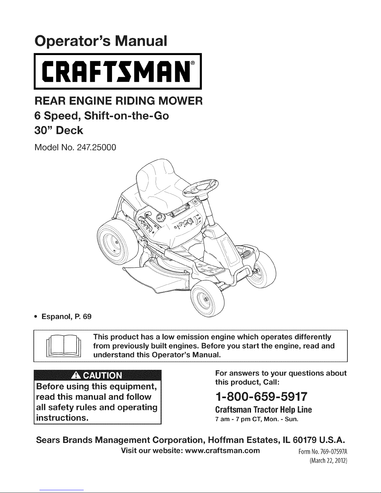
REAR ENGINE RiDiNG MOWER
6 Speed, Shift-on=the=Go
30" Deck
Model No. 247.25000
• Espanol, P. 69
This product has a low emission engine which operates differently
from previously built engines. Before you start the engine, read and
understand this Operator's Manual.
Before using this equipment,
read this manual and follow
all safety rules and operating
instructions.
Sears Brands Management Corporation, Hoffman Estates, IL 60179 U.S.A.
Visit our website: www.craftsman.com FormNo.769-07597A
For answers to your questions about
this product, Call:
1-800=659=5917
CraftsmanTractorHelpLine
7 am =7 pm CT, Mort. =Sun.
(March22,2012)
Page 2

Warranty Statement .......................................................... 2
Safety Instructions ............................................................ 3
Slope Gauge ..................................................................... 9
Assembly ......................................................................... 10
Operation ........................................................................ 15
Service and Maintenance .............................................. 21
Off-Season Storage ........................................................ 32
Trou bleshooting .............................................................. 33
Labels ............................................................................. 34
Parts List ......................................................................... 35
Espa_ol ............................................................................ 69
Service Numbers ............................................. Back Cover
CRAFTSMAN FULL WARRANTY
FORTWOYEARSfromthedateofpurchase,all non-expendablepartsof thisridingequipmentarewarrantedagainstanydefectsinmaterial
or workmanship.A defectivenon-expendablepartwill receivefreein-homerepairor replacementif repairisimpossible.
FORFIVEYEARSfromthedateof purchase,the frameandfrontaxleof thisridingequipmentarewarrantedagainstanydefectsinmaterialor
workmanship.A defectiveframeorfrontaxle willreceivefreein-homerepairor replacementif repairisimpossible.
FOR90 DAYSfromthedateofpurchase,thebattery(anexpendablepart)of this ridingequipmentiswarrantedagainstanydefectsin material
or workmanship(ourtestingprovesthatit willnotholda charge).A defectivebatterywillreceivefreein-homereplacement.
ADDITIONALLIFETIMELIMITEDWARRANTYon CASTIRON FRONTAXLE(if equipped)
FORAS LONGASITISUSEDby theoriginalownerafterthefifthyearfromthedateof purchase,the castironfrontaxle (ffequipped)of
this ridingequipmentiswarrantedagainstanydefectsinmaterialorworkmanship.With proofof purchase,a defectivecastironfrontaxle will
receivefree in-homereplacement.
WARRANTYSERVICE
Forwarrantycoveragedetailsto obtainfreerepairor replacement,call 1-800-659-5917or visitthewebsite:www.craftsman.corn
Inallcasesabove,ifpartrepairor replacementisimpossible,theridingequipmentwillbereplacedfreeofchargewiththesameoranequivalentmodel.
All oftheabovewarrantycoverageis voidifthis ridingequipmentisever usedwhileprovidingcommercialservicesorifrentedtoanother
person.
This warrantycovers ONLYdefects inmaterial andworkmanship. Warrantycoverage does NOTinclude:
• Expendableparts(exceptbattery)thatcan wearoutfromnormalusewithinthe warrantyperiod,includingbutnotlimitedtoblades,
sparkplugs,air cleaners,belts,andoilfilters.
• Standardmaintenanceservicing,oilchanges,ortune-ups.
• Tirereplacementor repaircausedbypuncturesfromoutsideobjects,suchasnails,thorns,stumps,orglass.
• Tireorwheel replacementor repairresultingfromnormalwear,accident,or improperoperationormaintenance.
• Repairsnecessarybecauseofoperatorabuse,includingbutnotlimitedto damagecausedbytowingobjectsbeyondthecapabilityof
the ridingequipment,impactingobjectsthatbendtheframe,axleassemblyorcrankshaft,orover-speedingtheengine.
• Repairsnecessarybecauseofoperatornegligence,includingbutnotlimitedto,electricalandmechanicaldamagecausedby
improperstorage,failuretousethepropergradeandamountofengineoil, failureto keepthedeckclearof flammabledebris,or
failureto maintainthe ridingequipmentaccordingto the instructionscontainedintheoperator'smanual.
• Engine(fuelsystem)cleaningorrepairscausedbyfueldeterminedto becontaminatedoroxidized(stale).Ingeneral,fuelshouldbe
usedwithin30 daysofits purchasedate.
• Normaldeteriorationand wearofthe exteriorfinishes,or productlabelreplacement.
Thiswarrantygivesyou specificlegalrights,andyoumayalsohaveotherrightswhichvaryfromstatetostate.
Sears BrandsManagementCorporation, Hoffman Estates, IL60179
EngineOil: SAE30
Fuel: UnleadedGasoline
SparkPlug: F6RTC(951-10292)
© KCDIRLLC
Model Number:
Serial Number:
Dateof Purchase:
Recordthe modelnumber,serialnumber,
anddateof purchaseabove.
2
Page 3
Thissymbolpointsout importantsafetyinstructionswhich,if not
followed,couldendangerthepersonalsafetyand/orpropertyof
yourselfandothers. Readandfollowallinstructionsin thismanual
beforeattemptingtooperatethismachine.Failureto complywith
theseinstructionsmayresultin personalinjury.Whenyouseethis
symbol,HEEDITSWARNING!
Thismachinewasbuiltto beoperatedaccordingtothesafeopera-
tionpracticesinthis manual.Aswithanytypeof powerequipment,
carelessnessorerroron the partoftheoperatorcanresultin serious
injury.Thismachineiscapableofamputatingfingers,hands,toes
andfeetandthrowingdebris.Failuretoobservethefollowingsafety
instructionscouldresultin seriousinjuryordeath.
CALIFORNIA PROPOSITION 65
EngineExhaust,someof itsconstituents,andcertainvehicle
componentscontainoremitchemicalsknownto StateofCalifornia
tocausecancerandbirthdefectsorotherreproductiveharm.
Batteryposts,terminals,and relatedaccessoriescontainleadand
leadcompounds,chemicalsknowntotheStateof Californiato
causecancerandreproductiveharm.Washhandsafterhandling.
GENERAL OPERATION
• Read,understand,andfollowall instructionsonthemachineand
in themanual(s)beforeattemptingto assembleandoperate.
Keepthis manualinasafeplaceforfutureand regularreference
andfororderingreplacementparts.
• Befamiliarwithall controlsandtheirproperoperation.Knowhow
tostopthe machineanddisengagethemquickly.
• Neverallowchildrenunder14yearsoldtooperatethis machine.
Children14yearsoldandover shouldreadandunderstandthe
operationinstructionsandsafetyrulesinthismanualandshould
betrainedandsupervisedbya parent.
• Neverallowadultstooperatethismachinewithoutproper
instruction.
• Tohelpavoidbladecontactor a thrownobjectinjury,keep
bystanders,helpers,childrenandpetsatleast75feetfromthe
machinewhile itisin operation.Stopmachineifanyoneenters
thearea.
• Thoroughlyinspecttheareawheretheequipmentis to be used.
Removeallstones,sticks,wire,bones,toys,andotherforeign
objectswhichcouldbe pickedupandthrownbytheblade(s).
Thrownobjectscancauseseriouspersonalinjury.
• Planyourmowingpatternto avoiddischargeofmaterialtoward
roads,sidewalks,bystandersandthe like.Also,avoiddischarg-
ingmaterialagainstawallorobstructionwhichmaycause
dischargedmaterialto ricochetbacktowardthe operator.
Your Responsibility--Restrict theuseof thispowermachineto
personswhoread,understandandfollowthewarningsand instruc-
tionsin thismanualandonthemachine.
SAVE THESE INSTRUCTIONS!
• Alwayswearsafetyglassesorsafetygogglesduringoperation
andwhileperformingan adjustmentorrepairto protectyoureyes.
Thrownobjectswhichricochetcancauseseriousinjurytothe
eyes.
• Wearsturdy,rough-soledworkshoesandclose-fittingslacksand
shirts.Loosefittingclothesandjewelrycanbe caughtin movable
parts.Neveroperatethismachineinbarefeetorsandals.
• Beawareofthemowerandattachmentdischargedirectionand
do notpointit at anyone.Donotoperatethemowerwithoutthe
dischargecoverorentiregrasscatcherinits properplace.
Donot puthandsorfeetnearrotatingpartsor underthecutting
deck.Contactwiththe blade(s)canamputatehandsandfeet.
A missingordamageddischargecovercancausebladecontact
or thrownobjectinjuries.
• Stoptheblade(s)whencrossinggraveldrives,walks,orroads
andwhilenotcuttinggrass.
• Watchfortrafficwhenoperatingnearorcrossingroadways.This
machineis notintendedforuseonanypublicroadway.
• Donotoperatethemachinewhileunderthe influenceofalcohol
or drugs.
• Mowonlyindaylightorgoodartificiallight.
Nevercarrypassengers.
• Disengageblade(s)beforeshiftingintoreverse.Backup slowly.
Alwayslookdownandbehindbeforeandwhilebackingto avoida
back-overaccident.
3
Page 4
• Slowdownbeforeturning.Operatethemachinesmoothly.Avoid
erraticoperationandexcessivespeed.
Disengageblade(s),setparkingbrake,stopengineandwaituntil
theblade(s)cometoa completestopbeforeremovinggrass
catcher,emptyinggrass,uncloggingchute,removinganygrassor
debris,or makinganyadjustments.
Neverleavea runningmachineunattended.Alwaysturnoff
blade(s),setparkingbrake,stopengineandremovekeybefore
dismounting.
Useextracarewhenloadingorunloadingthe machineintoa
trailerortruck.Thismachineshouldnotbedrivenupor down
ramp(s),becausethemachinecouldtip over,causingserious
personalinjury.Themachinemustbe pushedmanuallyon
ramp(s)to loadorunloadproperly.
Mufflerandenginebecomehotandcancausea burn.Donot
touch.
Checkoverheadclearancescarefullybeforedrivingunderlow
hangingtree branches,wires,dooropeningsetc.,wherethe
operatormaybestruckor pulledfromthe machine,whichcould
resultinseriousinjury.
Disengageallattachmentclutchesanddepressthe brakepedal
completelybeforeattemptingto startengine.
Yourmachineisdesignedto cutnormalresidentialgrassofa
heightnomorethan10".Donotattemptto mowthroughunusually
tall,drygrass(e.g.,pasture)orpilesof dry leaves.Drygrassor
leavesmaycontacttheengineexhaustand/orbuilduponthe
mowerdeckpresentinga potentialfire hazard.
Useonlyaccessoriesandattachmentsapprovedforthis machine
bythe machinemanufacturer.Read,understandandfollowall
instructionsprovidedwiththe approvedaccessoryorattachment.
Fora listof approvedaccessoriesandattachments,call 1-800-
659-5917.
Dataindicatesthatoperators,age60yearsandabove,are
involvedin alargepercentageofridingmower-relatedinjuries.
Theseoperatorsshouldevaluatetheirabilitytooperatetheriding
mowersafelyenoughto protectthemselvesandothersfrom
seriousinjury.
If situationsoccurwhicharenotcoveredinthismanual,usecare
andgoodjudgment.
SLOPE OPERATION
Slopesarea majorfactorrelatedtolossof controlandtip-over
accidentswhichcanresultinsevereinjuryor death.Allslopesrequire
extracaution.Ifyoucannotbackuptheslopeor if youfeeluneasyon
it, do notmowit.
Foryoursafety,usetheSlopeGuideincludedaspartofthis manual
to measureslopesbeforeoperatingthis machineona slopedor hilly
area.Ifthe slopeisgreaterthan12degreesasshownonthe Slope
Guide,do notoperatethismachineonthatareaor seriousinjurycould
result.
Do:
o
Mowupanddownslopes,notacross.Exerciseextremecaution
whenchangingdirectionon slopes.
• Watchforholes,ruts,bumps,rocks,orotherhiddenobjects.
Uneventerraincouldoverturnthe machine.Tallgrasscanhide
obstacles.
Useslowspeed.Choosea lowenoughspeedsettingsothat
youwill nothavetostopor shiftwhileon theslope.Tiresmay
losetractionon slopeseventhoughthe brakesarefunctioning
properly.Alwayskeepmachineingearwhen goingdownslopes
totakeadvantageofenginebrakingaction.
• Followthemanufacturer'srecommendationsforwheelweightsor
counterweightsto improvestability.
Useextracarewithgrasscatchersorotherattachments.These
canchangethestabilityof the machine.
Keepallmovementonthe slopesslowandgradual.Donot make
suddenchangesinspeedor direction.Rapidengagementor
brakingcouldcausethefrontof themachinetolift andrapidlyflip
overbackwardswhichcouldcauseseriousinjury.
• Avoidstartingorstoppingona slope.Iftireslosetraction,disen-
gagetheblade(s)andproceedslowlystraightdowntheslope.
DoNot:
• Donotturnonslopesunlessnecessary;then,turnslowlyand
graduallydownhill,ifpossible.
• Donotmowneardrop-offs,ditchesorembankments.Themower
couldsuddenlyturnoverif a wheelisovertheedgeofa cliff,
ditch,or ifan edgecavesin.
• Donottry to stabilizethemachinebyputtingyourfooton the
ground.
• Donotuseagrasscatcheronsteepslopes.
• Donotmowon wetgrass.Reducedtractioncouldcausesliding.
• Donotattempttocoastdownhill.Over-speedingmaycausethe
operatortolosecontrolof themachineresultingin seriousinjury
or death.
• Donottowheavypull behindattachments(e.g.loadeddumpcart,
lawnroller,etc.)on slopesgreaterthan5 degrees.Whengoing
downhill,theextraweighttendsto pushthetractorandmay
causeyouto loosecontrol(e.g.tractormayspeedup,brakingand
steeringabilityarereduced,attachmentmayjack-knifeandcause
tractorto overturn).
4
Page 5
CHILDREN
Tragicaccidentscanoccurifthe operatorisnotalertto thepresence
ofchildren.Childrenareoftenattractedto themachineandthemowing
activity.Theydo notunderstandthe dangers.Neverassumethat
childrenwillremainwhereyoulastsawthem.
• Keepchildrenoutofthemowingareaand inwatchfulcareof a
responsibleadultotherthantheoperator.
• Bealertandturnmachineoff ifa childentersthearea.
• Beforeandwhilebacking,lookbehindanddownforsmall
children.
Nevercarrychildren,evenwiththeblade(s)shutoff.Theymay
falloffandbe seriouslyinjuredorinterferewithsafemachine
operation.
• Useextremecarewhenapproachingblindcorners,doorways,
shrubs,treesorotherobjectsthatmayblockyourvisionofa child
whomayrunintothe machine.
Toavoidback-overaccidents,alwaysdisengagethe cutting
blade(s)beforeshiftingintoReverse.Ifequipped,the"Reverse
CautionMode"(bladesoperatewhilemachineridesinreverse)
shouldnotbe usedwhenchildrenorothersarearound.
Keepchildrenawayfromhotor runningengines.Theycansuffer
burnsfroma hotmuffler.
• Removekeywhenmachineisunattendedtopreventunauthorized
operation.
Neverallowchildrenunder14yearsofageto operatethismachine.
Children14andovershouldreadandunderstandtheinstructionsand
safeoperationpracticesinthismanualandon themachineandshould
betrainedandsupervisedbyan adult.
TOWING
Towonlywitha machinethathasa hitchdesignedfortowing.Do
notattachtowedequipmentexceptatthehitchpoint.
Followthemanufacturersrecommendationforweightlimitsfor
towedequipmentandtowingonslopes.
Neverallowchildrenor othersinoron towedequipment.
Onslopes,theweightof thetowedequipmentmaycauselossof
tractionandlossof control.
Alwaysuseextracautionwhentowingwitha machinecapableof
makingtightturns(e.g."zero-turn"ride-onmower). Makewide
turnstoavoidjack-knifing.
Travelslowlyandallowextradistancetostop.
Donotcoastdownhill.
SERVICE
SafeHandlingof Gasoline
Toavoidpersonalinjuryorpropertydamageuseextremecarein
handlinggasoline.Gasolineisextremelyflammableandthevaporsare
explosive.Seriouspersonalinjurycanoccurwhengasolineisspilled
on yourselforyourclotheswhichcanignite.Washyourskinand
changeclothesimmediately.
• Useonlyanapprovedgasolinecontainer.
Neverfill containersinsidea vehicleoron atruckortrailerbed
witha plasticliner.Alwaysplacecontainerson thegroundaway
fromyourvehiclebeforefilling.
Whenpractical,removegas-poweredequipmentfromthe truck
or trailerandrefuelitontheground.Ifthis isnotpossible,then
refuelsuchequipmentona trailerwitha portablecontainer,rather
thanfroma gasolinedispensernozzle.
Keepthenozzleincontactwiththe rimofthefueltankor
containeropeningat all timesuntilfuelingiscomplete.Donotuse
a nozzlelock-opendevice.
Extinguishall cigarettes,cigars,pipesandothersourcesof
ignition.
• Neverfuelmachineindoors.
Neverremovegascapor addfuelwhilethe engineis hotorrun-
ning.Allowengineto coolatleasttwominutesbeforerefueling.
Neveroverfillfuel tank. Filltanktono morethan1/2inchbelow
bottomoffillerneckto allowspaceforfuelexpansion.
• Replacegasolinecapandtightensecurely.
• Ifgasolineisspilled,wipeitoff the engineandequipment.Move
machineto anotherarea.Wait5 minutesbeforestartingthe
engine.
• Toreducefirehazards,keepmachinefree of grass,leaves,or
otherdebrisbuild-up.Cleanup oilor fuelspillageandremoveany
fuelsoakeddebris.
• Neverstorethemachineor fuelcontainerinsidewherethereisan
openflame,sparkor pilotlight as ona waterheater,spaceheater,
furnace,clothesdryeror othergasappliances.
Allowa machineto coolat leastfiveminutesbeforestoring.
Page 6
GeneralService
• Neverrunanengineindoorsor ina poorlyventilatedarea.Engine
exhaustcontainscarbonmonoxide,anodorless,anddeadlygas.
• Beforecleaning,repairing,orinspecting,makecertaintheblade(s)
andall movingpartshavestopped.Disconnectthesparkplugwire
andgroundagainsttheenginetopreventunintendedstarting.
• Periodicallycheckto makesurethebladescometocomplete
stopwithinapproximately(5)five secondsafteroperatingthe
bladedisengagementcontrol.Ifthebladesdonotstopwithinthe
thistimeframe,yourmachineshouldbeservicedprofessionally
bya Searsorotherqualifiedservicedealer.
• Checkbrakeoperationfrequentlyas it is subjectedto wearduring
normaloperation.Adjustand serviceas required.
• Checkthe blade(s)andenginemountingboltsat frequent
intervalsforpropertightness.Also,visuallyinspectblade(s)
fordamage(e.g.,excessivewear,bent,cracked).Replacethe
blade(s)withtheoriginalequipmentmanufacturer's(O.E.M.)
blade(s)only,listedinthismanual.Useof partswhichdo not
meettheoriginalequipmentspecificationsmayleadto improper
performanceandcompromisesafety!
• Mowerbladesaresharp.Wrapthebladeorweargloves,anduse
extracautionwhenservicingthem.
• Keepall nuts,bolts,andscrewstightto besuretheequipmentis
insafeworkingcondition.
• Nevertamperwiththesafetyinterlocksystemor othersafety
devices.Checktheirproperoperationregularly.
• Afterstrikingaforeignobject,stoptheengine,disconnectthe
sparkplugwire(s)andgroundagainsttheengine.Thoroughly
inspectthemachineforanydamage.Repairthedamagebefore
startingandoperating.
• Neverattempttomakeadjustmentsor repairstothe machine
whilethe engineis running.
• Grasscatchercomponentsandthedischargecoveraresubject
towearanddamagewhichcouldexposemovingpartsor allow
objectsto bethrown.Forsafetyprotection,frequentlycheck
componentsand replaceimmediatelywithoriginalequipment
manufacturer's(O.E.M.)partsonly,listedinthis manual.Useof
partswhichdo notmeettheoriginalequipmentspecificationsmay
leadtoimproperperformanceandcompromisesafety!
• Donotchangetheenginegovernorsettingsor over-speedthe
engine.Thegovernorcontrolsthe maximumsafeoperatingspeed
ofthe engine.
• Maintainor replacesafetyandinstructionlabels,as necessary.
• Observeproperdisposallawsandregulationsforgas,oil, etc.to
protecttheenvironment.
• Accordingtothe ConsumerProductsSafetyCommission(CPSC)
andtheU.S.EnvironmentalProtectionAgency(EPA),thisproduct
hasan AverageUsefulLifeof seven(7)years,or270hours
ofoperation.Attheendof theAverageUsefulLife,buya new
machineor havethemachineinspectedannuallybya Searsor
otherqualifiedservicedealerto ensurethatallmechanicaland
safetysystemsare workingproperlyand notwornexcessively.
Failuretodo socanresultinaccidents,injuriesordeath.
DO NOT MODIFY ENGINE
Toavoid seriousinjuryor death,do notmodifyengineinanyway.
Tamperingwiththegovernorsettingcanleadto a runawayengineand
causeitto operateat unsafespeeds.Nevertamperwithfactorysetting
ofenginegovernor.
NOTICE REGARDING EMISSIONS
Engineswhicharecertifiedto complywithCaliforniaandfederal
EPAemissionregulationsforSORE(SmallOffRoadEquipment)are
certifiedto operateonregularunleadedgasoline,andmayinclude
thefollowingemissioncontrolsystems:EngineModification(EM)and
ThreeWayCatalyst(TWO)if soequipped.
SPARK ARRESTOR
Ifa sparkarrestoris used,it shouldbemaintainedin effectiveworking
orderbythe operator.IntheStateof Californiatheaboveis required
bylaw (Section4442of the CaliforniaPublicResourcesCode).Other
statesmayhavesimilarlaws.Federallawsapplyonfederallands.
A sparkarrestorforthemufflerisavailablethroughyournearestSears
PartsandRepairServiceCenter.
SAFETY SYMBOLS
Thispagedepictsanddescribessafetysymbolsthat mayappear
on thisproduct. Read,understand,andfollowall instructionson the
machinebeforeattemptingtoassembleandoperate.
Thismachineisequippedwithan internalcombustionengineand
shouldnot beusedonornearanyunimprovedforest-covered,
brushcoveredor grass-coveredlandunlesstheengine'sexhaust
systemisequippedwitha sparkarrestormeetingapplicablelocalor
statelaws(if any).
6
Page 7
...._ •
s j/
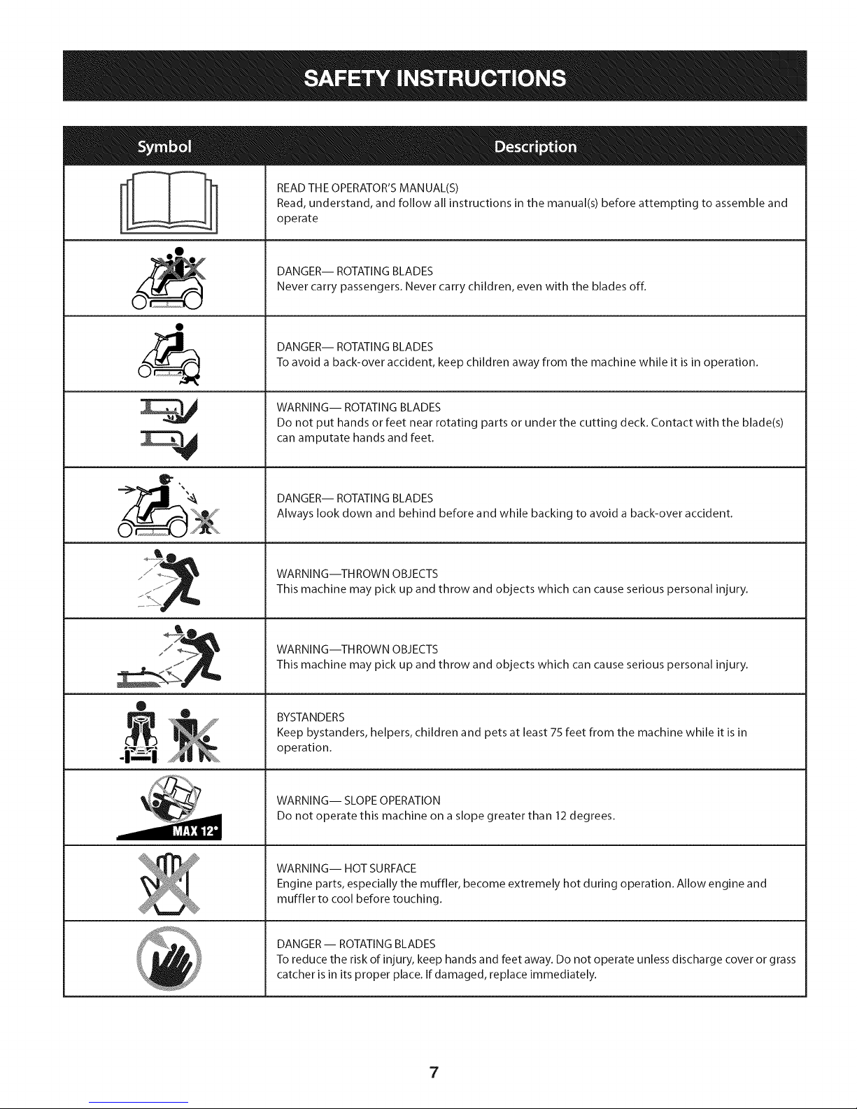
READ THE OPERATOR'S MANUAL(S)
Read, understand, and follow all instructions in the manual(s) before attempting to assemble and
operate
DANGER-- ROTATING BLADES
Never carry passengers. Never carry children, even with the blades off.
DANGER-- ROTATING BLADES
To avoid a back-over accident, keep children away from the machine while it is in operation.
WARNING-- ROTATING BLADES
Do not put hands or feet near rotating parts or under the cutting deck. Contact with the blade(s)
can amputate hands and feet.
DANGER-- ROTATING BLADES
Always look down and behind before and while backing to avoid a back-over accident.
WARNING--THROWN OBJECTS
jZ
This machine may pick up and throw and objects which can cause serious personal injury.
WARNING--THROWN OBJECTS
This machine may pick up and throw and objects which can cause serious personal injury.
®
BYSTANDERS
Keep bystanders, helpers, children and pets at least 75 feet from the machine while it is in
operation.
WARNING-- SLOPE OPERATION
Do not operate this machine on a slope greater than 12 degrees.
WARNING-- HOT SURFACE
Engine parts, especially the muffler, become extremely hot during operation. Allow engine and
muffler to cool before touching.
DANGER-- ROTATING BLADES
To reduce the risk of injury, keep hands and feet away. Do not operate unless discharge cover or grass
catcher is in its proper place. If damaged, replace immediately.
7
Page 8
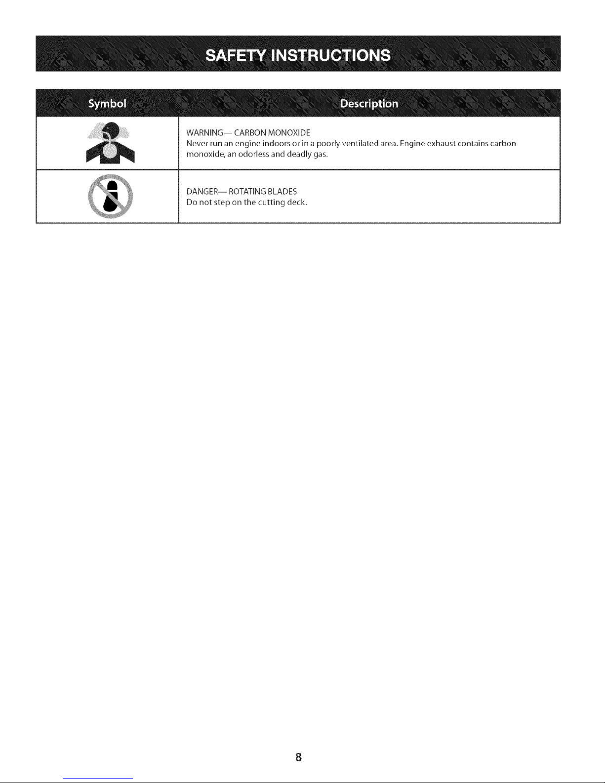
WARNING-- CARBON MONOXIDE
Never run an engine indoors or in a poorly ventilated area. Engine exhaust contains carbon
monoxide, an odorless and deadly gas.
DANGER-- ROTATING BLADES
Do not step on the cutting deck.
8
Page 9
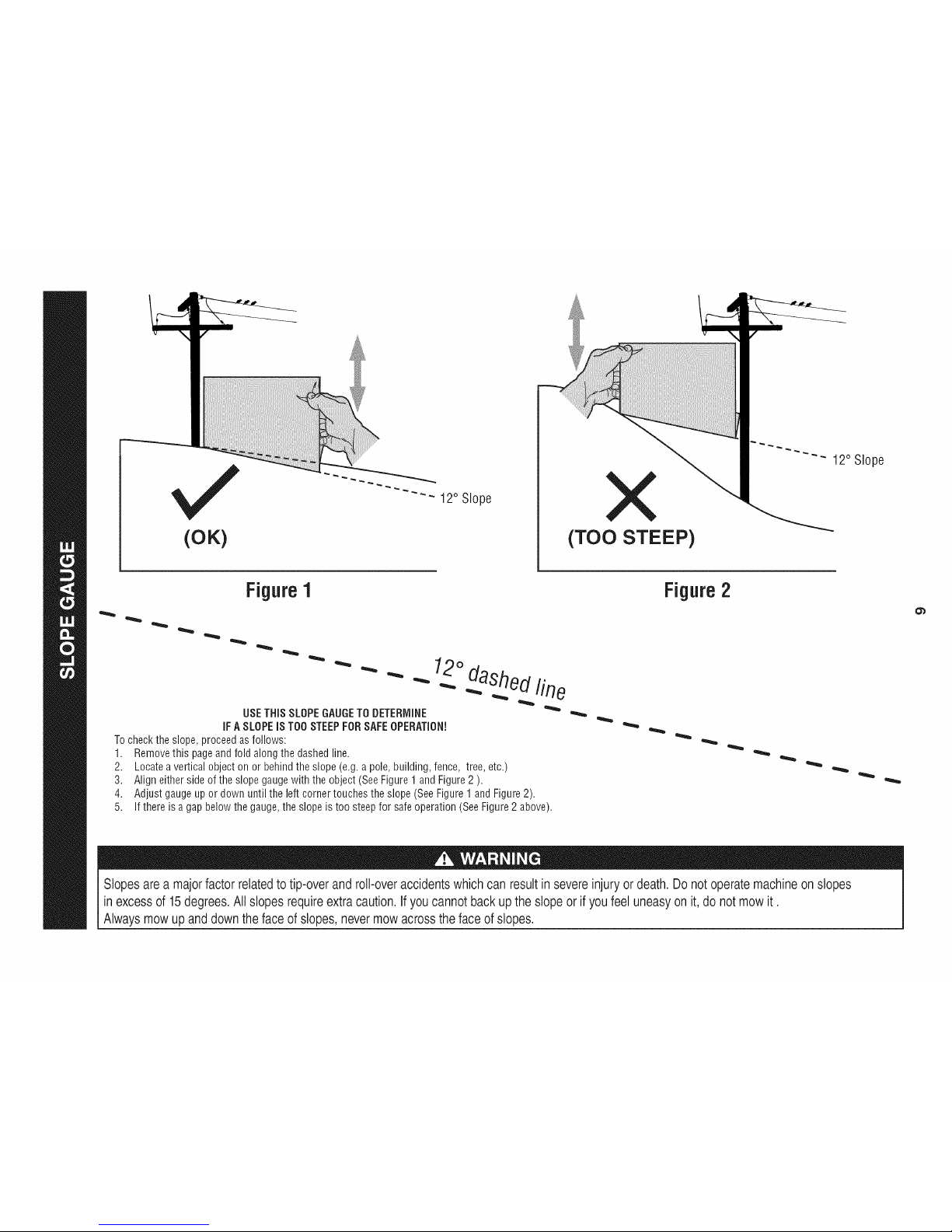
(OK)
iiiii!i!i!i!i!i!i!i! ! ! ! !iiiiii!ii!!i
X
(TO0 STEEP)
12° Slope
Figure1
USETHiSSLOPEGAUGETODETERMINE
iFASLOPEiSTOOSTEEPFORSAFEOPERATION!
Tochecktheslope,proceedasfollows:
1. Removethis pageandfold alongthedashedline.
2. Locateaverticalobjectonor behindtheslope(e.g.apole,building,fence,tree,etc.)
3. Aligneithersideof theslopegaugewiththeobject(SeeFigure1andFigure2 ).
4. Adjustgaugeupor down untilthe leftcornertouchestheslope(SeeFigure1 andFigure2).
5.
If thereisa gapbelowthegauge,theslopeis toosteepfor safeoperation(SeeFigure2 above).
Figure2
Slopes area majorfactor related totip-over and roll-overaccidents which can result in severeinjury or death. Do not operate machineon slopes
in excessof 15degrees. Allslopes requireextra caution.If you cannotback up the slope or if you feel uneasy on it,do not mowit.
Always mowup and down the face of slopes, nevermow acrossthe face of slopes.
Page 10
Contentsof Crate
• OneRidingMower
OneSteeringWheel/ShaftAssembly
OneRearHitchPlate
OneRidingMowerOperator'sManual
OneSeatAssembly
OneRearEngineCover
OneOilDrainSleeve
OneEngineOperator'sManual
CONTENTS OF HARDWARE PACK
Beforebeginninginstallation,removeallthe contentsfromthecrate
andallthehardwarefromthepackfromto makesureeverything
ispresent.Hardwareis listedbelow.Partnumbersare shownin
parentheses.
• Two5/16-18x 3/4"Screws-- HitchPlate(710-3008)
• Two5/16-18LockNuts-- HitchPlate(712-04063)
• Two1/4-15x 1"Screws-- EngineRearCover(710-1241)
• TwoShoulderBolts-- SeatPivotBracket(738-0140)
• Two5/16-18LockNuts-- SeatPivotBracket(712-04063)
• One1/4-20x 3/4" Screw-- SteeringPedestal(710-0924)
• One3/16HexKey-- SteeringShaft(710-05046)
RECOMMENDED TOOLS FOR ASSEMBLY
• 3/16"HexKey(includedinhardwarepack)
• 1/4"DriveRatchet
• 3/16"Wrench(oradjustablewrench)
• 3/8"Wrench(oradjustablewrench)
• 1/2"Wrench(oradjustablewrench)
• 5/8"Wrench(oradjustablewrench)
• 3/8"Socketwrench
• 1/2" Socketwrench
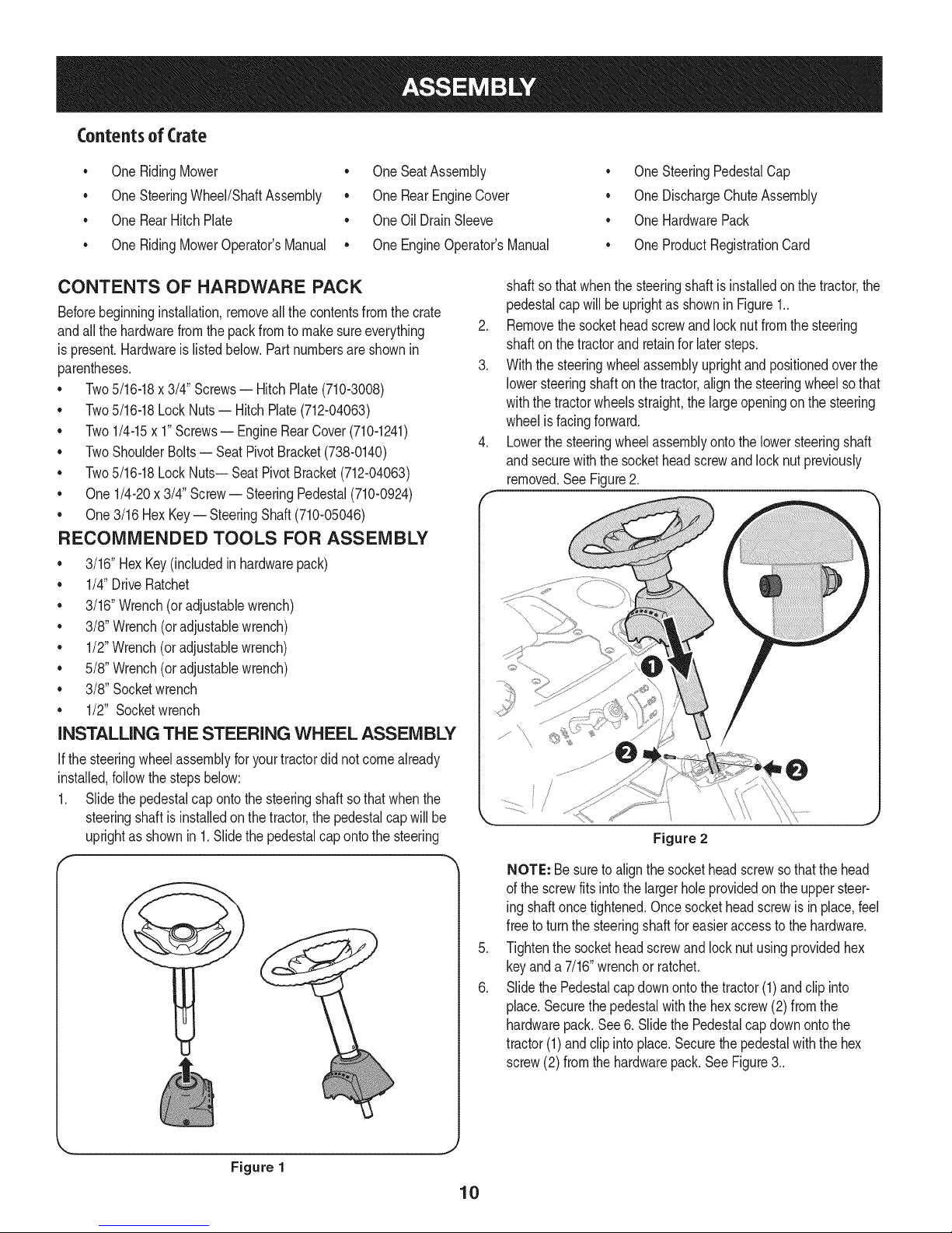
INSTALLING THE STEERING WHEEL ASSEMBLY
If thesteeringwheelassemblyforyourtractordidnotcomealready
installed,followthestepsbelow:
1. Slidethepedestalcapontothe steeringshaftsothatwhenthe
steeringshaftis installedonthetractor,the pedestalcap willbe
uprightas shownin 1.Slidethe pedestalcapontothesteering
OneSteeringPedestalCap
OneDischargeChuteAssembly
• OneHardwarePack
• OneProductRegistrationCard
shaftso thatwhenthesteeringshaft isinstalledon thetractor,the
pedestalcapwill beuprightas shownin Figure1..
2. Removethesocketheadscrewandlocknut fromthe steering
shaftonthe tractorandretainfor latersteps.
3. Withthesteeringwheelassemblyuprightandpositionedoverthe
lowersteeringshaftonthetractor,alignthe steeringwheelsothat
withthetractorwheelsstraight,thelargeopeningonthe steering
wheelis facingforward.
4. Lowerthesteeringwheelassemblyontothe lowersteeringshaft
and securewiththesocketheadscrewandlocknut previously
removed.SeeFigure2.
Figure 2
Figure 1
NOTE: Besureto alignthe socketheadscrewsothatthehead
ofthe screwfitsintothelargerholeprovidedon theuppersteer-
ing shaftoncetightened.Oncesocketheadscrewis in place,feel
freeto turnthesteeringshaftforeasieraccesstothe hardware.
.
Tightenthesocketheadscrewand locknutusingprovidedhex
keyanda 7/16"wrenchor ratchet.
6.
SlidethePedestalcapdownontothetractor(1)andclip into
place.Securethepedestalwiththehex screw(2)fromthe
hardwarepack.See6.Slidethe Pedestalcapdownontothe
tractor(1)andclip intoplace.Securethepedestalwiththe hex
screw(2) fromthehardwarepack.SeeFigure3..
Page 11
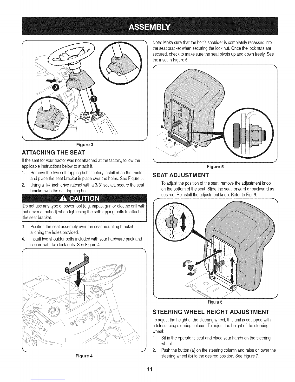
Figure 3
ATTACHING THE SEAT
If theseatforyourtractorwasnotattachedatthefactory,followthe
applicableinstructionsbelowtoattachit.
1. Removethetwo self-tappingboltsfactoryinstalledon the tractor
andplacethe seatbracketinplaceovertheholes.SeeFigure5.
2. Usinga 1/4-inchdrive ratchetwitha 3/8"socket,securetheseat
bracketwiththe self-tappingbolts.
Note:Makesurethatthebolt'sshoulderiscompletelyrecessedinto
theseatbracketwhensecuringthe locknut.Oncethelocknutsare
secured,checkto makesurethe seatpivotsupanddownfreely.See
theinsetin Figure5.
Figure 5
SEAT ADJUSTMENT
1. Toadjustthepositionof theseat,removetheadjustmentknob
on thebottomoftheseat.Slidethe seatforwardor backwardas
desired.Reinstalltheadjustmentknob.Referto Fig.6.
Donotuseanytypeof powertool(e.g.impactgunorelectricdrillwith
nutdriverattached)whentighteningthe self-tappingboltsto attach
theseatbracket.
3. Positionthe seatassemblyovertheseatmountingbracket,
aligningtheholesprovided.
4. Installtwoshoulderboltsincludedwithyourhardwarepackand
securewithtwolocknuts.SeeFigure4.
\\
Figure 4
\
Figura6
STEERING WHEEL HEIGHT ADJUSTMENT
Toadjustthe heightofthe steeringwheel,thisunit isequippedwith
a telescopingsteeringcolumn.Toadjusttheheightofthesteering
wheel:
1. Sitinthe operator'sseatandplaceyourhandsonthe steering
wheel.
2. Pushthebutton(a)on thesteeringcolumnandraiseor lowerthe
steeringwheel(b)to thedesiredposition.SeeFigure7.
11
Page 12
NOTE: Oncethe desiredpositionisachieved,lift upanddownonthe
steeringwheelto makesureit locksintoplaceandthebutton(a)on
thesteeringcolumnreleasesintoa lockedposition.Donotoperatethis
unitunlessthe steeringcolumnis ina lockedposition.
Figure 7
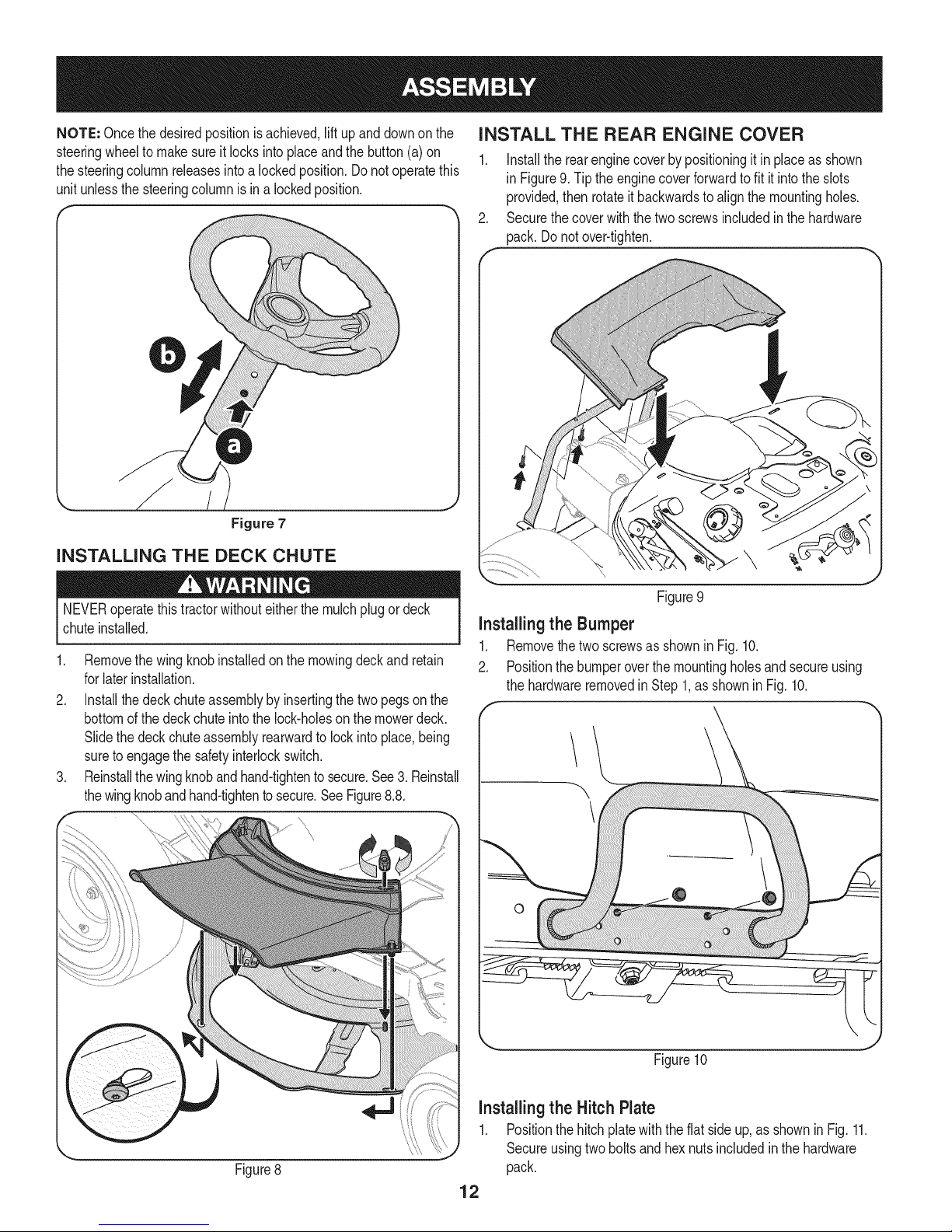
INSTALLING THE DECK CHUTE
INSTALL THE REAR ENGINE COVER
1. Installtherearenginecoverbypositioningit inplaceasshown
in Figure9.Tiptheenginecoverforwardtofit it intothe slots
provided,then rotateit backwardsto alignthemountingholes.
2. Securethecoverwiththetwo screwsincludedinthe hardware
pack.Donotover-tighten.
NEVERoperatethistractorwithouteitherthe mulchplugor deck
chuteinstalled.
1. Removethewing knobinstalledonthemowingdeckand retain
forlaterinstallation.
2. Installthedeckchuteassemblybyinsertingthetwo pegsonthe
bottomofthedeckchuteintothelock-holeson themowerdeck.
Slidethedeckchuteassemblyrearwardto lockinto place,being
sureto engagethesafetyinterlockswitch.
3. Reinstallthewingknobandhand-tightentosecure.See3.Reinstall
thewingknobandhand-tightento secure.SeeFigure8.8.
\
Figure9
Installingthe Bumper
1. Removethetwoscrewsasshownin Fig.10.
2. Positionthebumperoverthe mountingholesandsecureusing
thehardwareremovedin Step1,asshowninFig. 10.
Figure8
Figure10
installingthe Hitch Plate
1. Positionthe hitchplatewiththeflat sideup,asshownin Fig.11.
Secureusingtwoboltsandhexnutsincludedinthehardware
pack.
12
Page 13
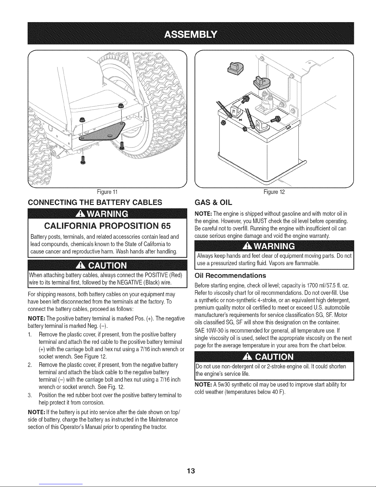
Figure11
CONNECTING THE BATTERY CABLES
CALiFORNiA PROPOSITION 65
Batteryposts,terminals,and relatedaccessoriescontainleadand
leadcompounds,chemicalsknowntotheStateof Californiato
causecancerandreproductiveharm.Washhandsafterhandling.
Figure12
GAS & OIL
NOTE: Theengineis shippedwithoutgasolineandwithmotoroil in
theengine.However,youMUSTchecktheoil levelbeforeoperating.
Becarefulnotto overfill.Runningtheenginewithinsufficientoilcan
causeseriousenginedamageandvoidthe enginewarranty.
Alwayskeephandsandfeetclearofequipmentmovingparts.Donot
usea pressurizedstartingfluid.Vaporsare flammable.
Whenattachingbatterycables,alwaysconnectthePOSITIVE(Red)
wireto its terminalfirst,followedby theNEGATIVE(Black)wire.
Forshippingreasons,bothbatterycablesonyourequipmentmay
havebeenleft disconnectedfromtheterminalsatthefactory.To
connectthebatterycables,proceedasfollows:
NOTE: ThepositivebatteryterminalismarkedPos.(+).Thenegative
batteryterminalis markedNeg.(-).
1. Removetheplasticcover,if present,fromthepositivebattery
terminalandattachthe redcabletothe positivebatteryterminal
(+)withthecarriageboltandhexnutusinga 7/16inchwrenchor
socketwrench.SeeFigure12.
2. Removetheplasticcover,if present,fromthenegativebattery
terminalandattachtheblackcabletothe negativebattery
terminal(-) withthecarriageboltandhex nutusinga7/16inch
wrenchor socketwrench.SeeFig.12.
3. Positionthe redrubberbootoverthepositivebatteryterminalto
helpprotectit fromcorrosion.
NOTE: Ifthe batteryisputintoserviceafterthedateshownontop/
sideof battery,chargethebatteryasinstructedinthe Maintenance
sectionof thisOperator'sManualpriorto operatingthetractor.
Oil Recommendations
Beforestartingengine,checkoil level;capacityis 1700ml/57.5ft.oz.
Referto viscositychartfor oil recommendations.Donotover-fill.Use
a syntheticornon-synthetic4-stroke,or anequivalenthighdetergent,
premiumqualitymotoroil certifiedto meetor exceedU.S.automobile
manufacturer'srequirementsforserviceclassificationSG,SEMotor
oilsclassifiedSG,SFwill showthisdesignationonthecontainer.
SAE10W-30isrecommendedforgeneral,alltemperatureuse.If
singleviscosityoilis used,selecttheappropriateviscosityon thenext
pagefortheaveragetemperaturein yourareafromthechartbelow.
Donot usenon-detergentoil or2-strokeengineoil. Itcouldshorten
theengine'sservicelife.
NOTE: A5w30syntheticoil maybeusedtoimprovestartabilityfor
coldweather(temperaturesbelow40 F).
13
Page 14
mE/ml,
Useautomotivegasoline(unleadedor lowleadedto minimizecombus-
tionchamberdeposits)witha minimumof 87 octane.Gasolinewith
up to 10%ethanolor 15%MTBE(MethylTertiaryButylEther)canbe
V
used.Neverusean oil/gasolinemixtureordirty gasoline.Avoidgetting
dirt, dust,orwaterinthefueltank.DONOTuse E85gasoline.
mmmmm_
m mlb
(°C)-30o -20o -I0o 0o 100 200 300 400
(oF)-20o 0o 15o 300 500 700 850 1050
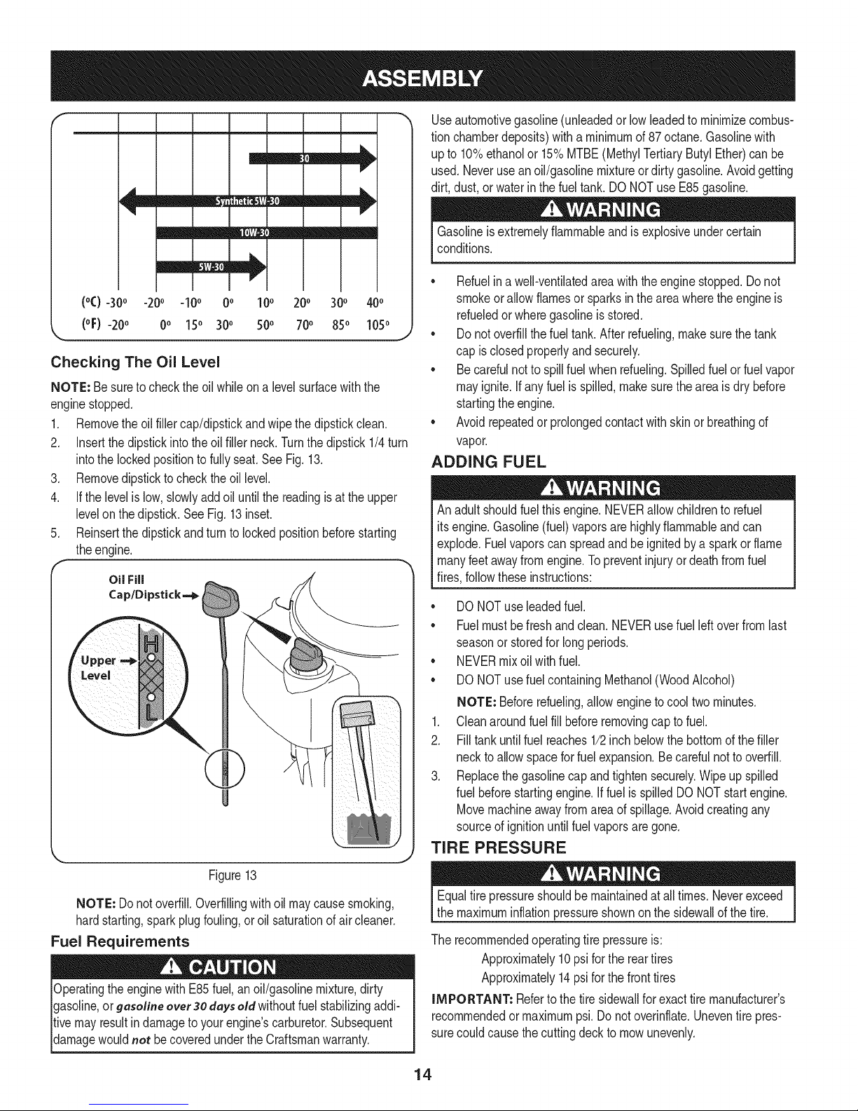
Checking The Oil Level
NOTE: Besuretochecktheoilwhileon a levelsurfacewiththe
enginestopped.
1. Removetheoil fillercap/dipstickandwipethedipstickclean.
2. Insertthe dipstickintothe oil fillerneck.Turnthedipstick1/4turn
intothelockedpositionto fullyseat.See Fig.13.
3. Removedipsticktochecktheoil level.
4. Ifthe levelislow,slowlyaddoiluntilthereadingisattheupper
levelonthe dipstick.SeeFig.13inset.
5. Reinsertthedipstickandturnto lockedpositionbeforestarting
theengine.
Oil Fill
Cap/Dipstick--_
Level
Figure13
NOTE: Donotoverfill.Overfillingwithoil maycausesmoking,
hardstarting,sparkplugfouling,oroil saturationofair cleaner.
Fuel Requirements
Operatingtheenginewith E85fuel,anoil/gasolinemixture,dirty
gasoline,or gasolineover 30daysold withoutfuelstabilizingaddi-
tivemayresultin damagetoyourengine'scarburetor.Subsequent
damagewouldnot becoveredundertheCraftsmanwarranty.
Gasolineisextremelyflammableand isexplosiveundercertain
conditions.
,, Refuelina well-ventilatedareawiththeenginestopped.Donot
smokeorallowflamesor sparksintheareawheretheengineis
refueledor wheregasolineisstored.
* Donot overfillthefueltank.After refueling,makesurethetank
J
capis closedproperlyandsecurely.
* Becarefulnotto spillfuelwhenrefueling.Spilledfuelorfuel vapor
mayignite.Ifanyfuelis spilled,makesuretheareaisdrybefore
startingthe engine.
* Avoidrepeatedorprolongedcontactwithskinor breathingof
vapor.
ADDING FUEL
Anadultshouldfuelthis engine.NEVERallowchildrentorefuel
itsengine.Gasoline(fuel)vaporsarehighlyflammableandcan
explode.Fuelvaporscanspreadandbeignitedbya sparkorflame
manyfeetawayfromengine.Topreventinjuryordeathfromfuel
fires,followtheseinstructions:
* DONOTuseleadedfuel.
* Fuelmustbefreshandclean.NEVERusefuel leftoverfromlast
seasonor storedforlongperiods.
* NEVERmixoilwithfuel.
* DONOTusefuelcontainingMethanol(WoodAlcohol)
NOTE: Beforerefueling,allowenginetocooltwo minutes.
1. Cleanaroundfuelfillbeforeremovingcap tofuel.
2. Filltankuntilfuel reaches1/2inchbelowthe bottomofthefiller
necktoallowspaceforfuel expansion.Becarefulnottooverfill.
3. Replacethegasolinecapand tightensecurely.Wipe upspilled
fuelbeforestartingengine.Iffuelis spilledDONOTstartengine.
Movemachineawayfromareaof spillage.Avoidcreatingany
sourceof ignitionuntilfuelvaporsaregone.
TIRE PRESSURE
,J
Equaltirepressureshouldbemaintainedat alltimes.Neverexceed
themaximuminflationpressureshownonthesidewallof thetire.
Therecommendedoperatingtirepressureis:
Approximately10psiforthe reartires
Approximately14psiforthefronttires
IMPORTANT: Refertothetiresidewallfor exacttiremanufacturer's
recommendedormaximumpsi.Donotoverinflate.Uneventire pres-
surecould causethecuttingdeckto mowunevenly.
14
Page 15
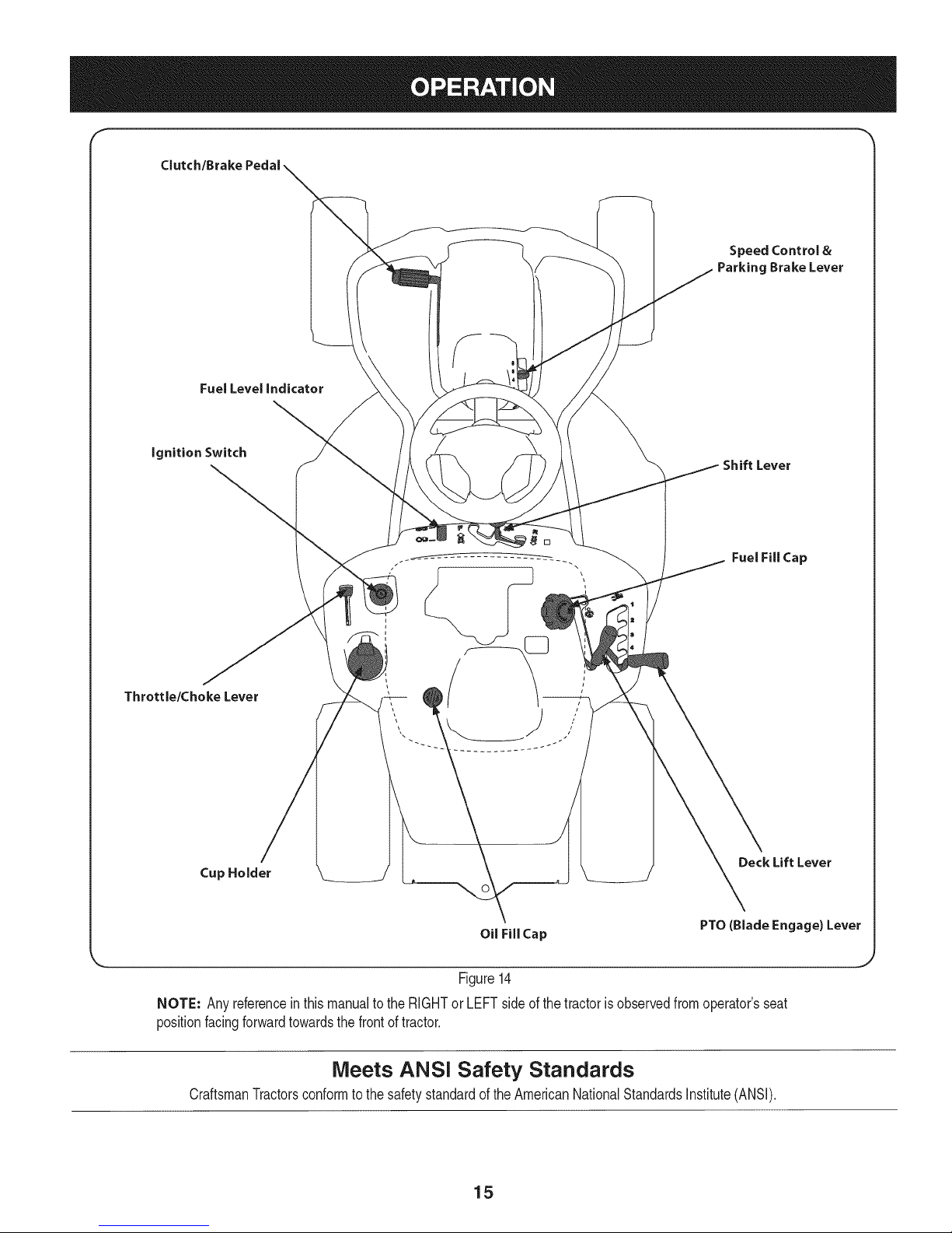
Clutch/Brake
Fuel Level indicator
Speed Control &
Parking Brake Lever
ignition Switch
Throttle/Choke Lever
Cup Holder
Shift Lever
[]
Fuel Fill Cap
Deck Lift Lever
NOTE: Anyreferenceinthismanualtothe RIGHTorLEFTside ofthetractorisobservedfromoperator'sseat
positionfacingforwardtowardsthe frontof tractor.
CraftsmanTractorsconformtothe safetystandardof theAmericanNationalStandardsInstitute(ANSI).
Oil Fill Cap
Figure14
Meets ANSi Safety Standards
15
PTO(Blade Engage) Lever
Page 16
Throttle / Choke Control
Thethrottlecontrolleveris locatedon the leftfenderof the tractoras
seenfromthe operator'sposition,seeFig. 14.Thislevercontrolsthe
speedof theengine,aswellas the chokewhenitispushedallthe
wayforward.Whensetina givenposition,thethrottlewillmaintaina
uniformenginespeed.
iMPORTANT: Whenoperatingthetractorwiththe cuttingdeck
engaged,becertainthatthe throttleleverisalwaysintheFAST
(rabbit)position.
Movingthethrottleleverall thewayforwardactivatestheengine's
chokecontrol. Activatingthechokecontrolclosesthechokeplateon
thecarburetorandaids instartingtheengine.
RefertoStartingThe EngineintheOperationsectionofthis manual
fordetailedstartinginstructions.
ignition Switch
Theignitionswitchislocatedon theleftfenderofthetractorasseen
fromtheoperator'sposition,adjacenttothe Throttle/ChokeControl.
Activatethe ignitionSwitchtostarttheengineby insertingthekeyinto
theignitionswitchand turnclockwisetothe STARTposition.Release
thekeyintothe ONpositiononceenginehasfired.SeeFig.15.
On
Start
off
Figure 15
Clutch=Brake Pedal
Theclutch-brakepedalis locatedontheleftsideofthelawntractor,
alongtherunningboard.Depresstheclutch-brakepedalpartway
downwhenslowingthetractorbychangingspeeds(Refer to Speed
Control Lever). Depressthepedalallthewaydowntoengagethe
discbrakeandbringthetractortoa completestop.
NOTE: Theclutch-brakepedalmustbecompletelydepressedtostart
theengine.RefertoSafetyInterlockSwitchesinthe Operationsection
ofthismanual.
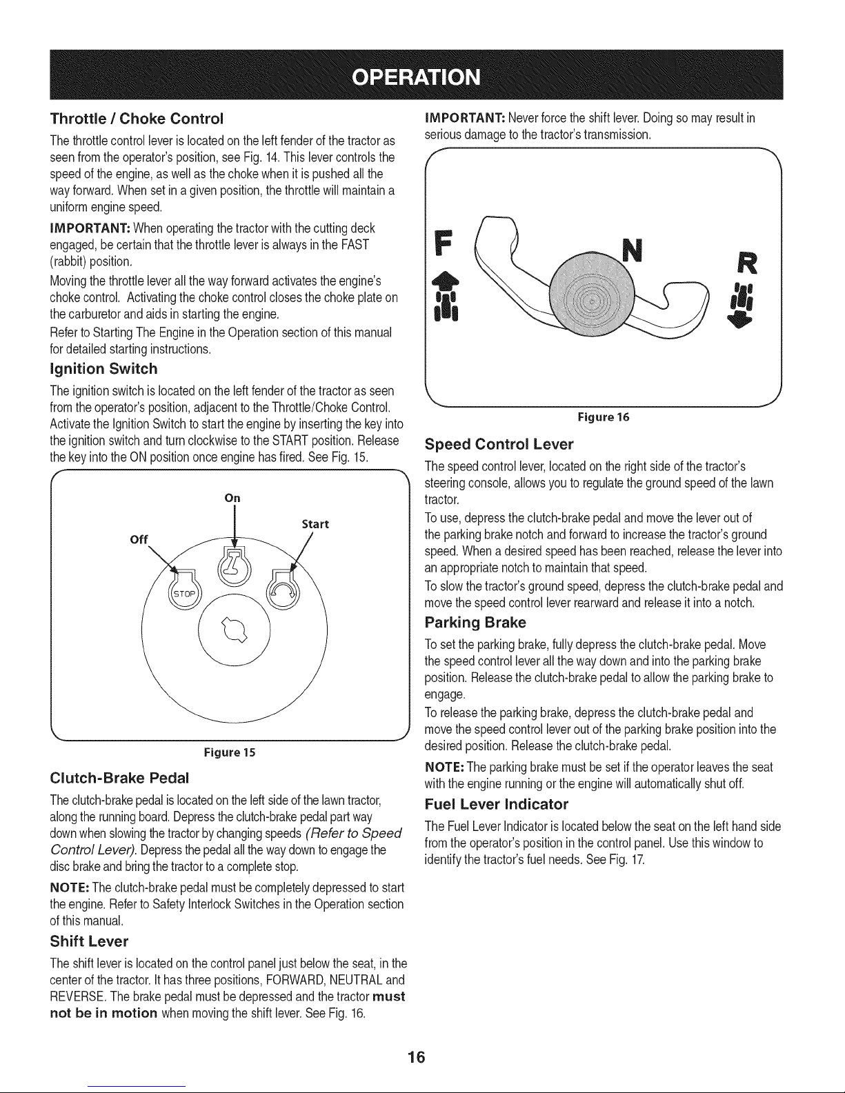
Shift Lever
iMPORTANT: Neverforcethe shiftlever.Doingsomayresultin
seriousdamagetothetractor'stransmission.
f
N
Figure 16
Speed Control Lever
Thespeedcontrollever,locatedon therightside ofthetractor's
steeringconsole,allowsyoutoregulatethegroundspeedofthe lawn
tractor.
Touse,depressthe clutch-brakepedalandmovetheleveroutof
theparkingbrakenotchandforwardto increasethetractor'sground
speed.Whena desiredspeedhasbeenreached,releasetheleverinto
an appropriatenotchto maintainthatspeed.
Toslowthe tractor'sgroundspeed,depresstheclutch-brakepedaland
movethespeedcontrolleverrearwardand releaseitintoanotch.
Parking Brake
Tosetthe parkingbrake,fullydepresstheclutch-brakepedal.Move
thespeedcontrolleverallthe waydownandintotheparkingbrake
position.Releasetheclutch-brakepedaltoallowthe parkingbraketo
engage.
Toreleasetheparkingbrake,depresstheclutch-brakepedaland
movethespeedcontrolleveroutofthe parkingbrakepositionintothe
desiredposition.Releasethe clutch-brakepedal.
NOTE:The parkingbrakemustbesetif theoperatorleavestheseat
withtheenginerunningortheenginewillautomaticallyshutoff.
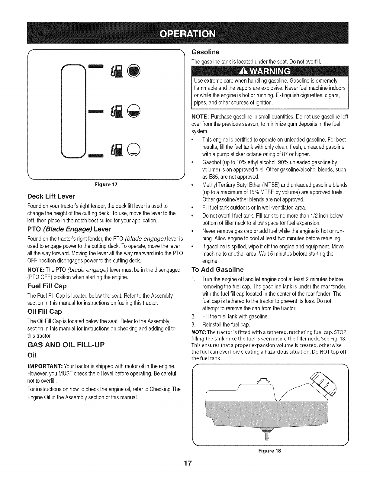
Fuel Lever Indicator
TheFuelLeverIndicatorislocatedbelowtheseatonthe left handside
fromtheoperator'spositioninthecontrolpanel.Usethiswindowto
identifythe tractor'sfuelneeds.SeeFig. 17.
Theshiftleveris locatedonthecontrolpaneljust belowtheseat,inthe
centerofthe tractor.Ithasthreepositions,FORWARD,NEUTRALand
REVERSE.The brakepedalmustbedepressedandthetractormust
not be in motion whenmovingtheshiftlever.SeeFig.16.
16
Page 17
©
Figure 17
Deck Lift Lever
Foundonyourtractor'srightfender,thedecklift leverisusedto
changetheheightof thecuttingdeck.Touse,movethe levertothe
left,then placeinthenotchbestsuitedforyourapplication.
PTO (Blade Engage) Lever
Foundonthe tractor'srightfender,thePTO (blade engage) leveris
usedto engagepowerto thecuttingdeck.Tooperate,movethelever
allthewayforward.Movingtheleverall thewayrearwardintothe PTO
OFFpositiondisengagespowertothecuttingdeck.
NOTE: ThePTO(blade engage) levermust beinthedisengaged
(PTOOFF)positionwhenstartingtheengine.
Fuel Fill Cap
TheFuelFillCap islocatedbelowtheseat.RefertotheAssembly
sectioninthismanualforinstructionsonfuelingthistractor.
Oil Fill Cap
TheOil FillCapislocatedbelowthe seat.RefertotheAssembly
sectioninthismanualforinstructionsoncheckingandaddingoilto
thistractor.
GAS AND OIL FILL-UP
Oil
IMPORTANT: Yourtractorisshippedwith motoroilinthe engine.
However,youMUSTchecktheoil levelbeforeoperating.Becareful
nottooverfill.
Forinstructionsonhowtochecktheengineoil, refertoCheckingThe
EngineOilintheAssemblysectionof thismanual.
Gasoline
Thegasolinetankislocatedunderthe seat.Donot overfill.
Useextremecarewhenhandlinggasoline.Gasolineisextremely
flammableandthevaporsareexplosive.Neverfuelmachineindoors
orwhilethe engineis hotor running.Extinguishcigarettes,cigars,
pipes,andothersourcesof ignition.
NOTE : Purchasegasolineinsmallquantities.Donotusegasolineleft
overfromthe previousseason,to minimizegumdepositsinthe fuel
system.
• Thisengineiscertifiedtooperateonunleadedgasoline.Forbest
results,fill thefueltankwith onlyclean,fresh,unleadedgasoline
witha pumpstickeroctaneratingof87or higher.
• Gasohol(upto10%ethylalcohol,90%unleadedgasolineby
volume)isan approvedfuel.Othergasoline/alcoholblends,such
as E85,arenotapproved.
MethylTertiaryButylEther(MTBE)and unleadedgasolineblends
(uptoa maximumof 15%MTBEbyvolume)areapprovedfuels.
Othergasoline/etherblendsarenotapproved.
• Fillfueltankoutdoorsor inwell-ventilatedarea.
• Donotoverfillfueltank.Filltankto nomorethan1/2inchbelow
bottomoffillerneckto allowspaceforfuelexpansion.
• Neverremovegascap or addfuelwhiletheengineis hotor run-
ning.Allowengineto coolat leasttwominutesbeforerefueling.
• Ifgasolineisspilled,wipeitoff the engineandequipment.Move
machineto anotherarea.Wait5 minutesbeforestartingthe
engine.
Add GasolineTo
1.
Turntheengineoffand letenginecoolatleast2 minutesbefore
removingthefuelcap.Thegasolinetankis undertherearfender,
withthefuel fillcaplocatedinthecenterof therearfender The
fuelcap istetheredtothe tractortopreventitsloss.Donot
attemptto removethecap fromthetractor.
2. Fillthefueltankwithgasoline.
3. Reinstallthefuelcap.
NOTE: The tractor is fitted with a tethered, ratcheting fuel cap. STOP
filling the tank once the fuel is seen inside the filler neck. See Fig. 18.
This ensures that a proper expansion volume is created, otherwise
the fuel can overflow creating a hazardous situation. Do NOTtop off
the fuel tank.
Figure 18
17
Page 18
Safety interlockSwitches
Thesafetyinterlocksystemisdesignedforsafeoperationof thetrac-
tor.Ifthis systemshouldevermalfunction,donotoperatethetractor.
Immediatelycontact1-800i4iMY-HOMEto havethesystemserviced.
• Thesafetyinterlocksystempreventstheenginefromstarting
unlesstheparkingbrakeis engagedandthePTO(BladeEngage)
leveris inthedisengaged(OFF)position.
• Thesafetyinterlocksystemwillautomaticallyshutoff theengineif
theoperatorleavesthe seatbeforeengagingtheparkingbrake.
• Thesafetyinterlocksystemwill automaticallyshutoff theengine
ifthe operatorleavesthetractor'sseatwiththe PTO(Blade
Engage)leverengaged,regardlessofwhethertheparkingbrake
isengaged.
• Theenginewillautomaticallyshutoffif the PTO(BladeEngage)
leveris movedintotheengaged(ON)positionwiththeshiftlever
in Reverse.
Donot operatethetractoriftheinterlocksystemismalfunctioning.
Thissystemwasdesignedforyoursafetyand protection.
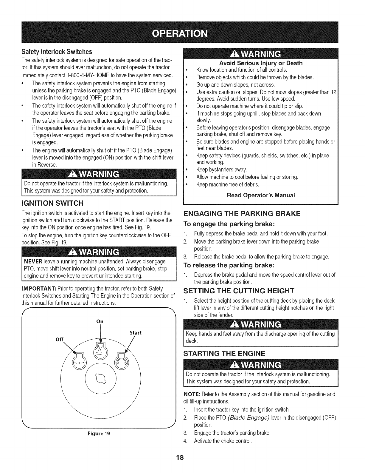
iGNiTiON SWITCH
Theignitionswitchisactivatedto starttheengine.Insertkeyintothe
ignitionswitchandturnclockwisetothe STARTposition.Releasethe
keyintothe ONpositiononceenginehasfired.SeeFig. 19.
Tostoptheengine,turntheignitionkeycounterclockwisetotheOFF
position.SeeFig. 19.
NEVER leavearunningmachineunattended.Alwaysdisengage
PTO,moveshiftleverintoneutralposition,setparkingbrake,stop
leng ne andremovekeyto preventunntendedstartng.
IMPORTANT: Priortooperatingthetractor,refertobothSafety
InterlockSwitchesandStartingThe EngineintheOperationsectionof
thismanualforfurtherdetailedinstructions.
On
Avoid Serious Injury or Death
• Knowlocationandfunctionofall controls.
• Removeobjectswhichcouldbe thrownbythe blades.
• Goup anddownslopes,notacross.
• Useextracautiononslopes.Donotmowslopesgreaterthan12
degrees.Avoidsuddenturns.Uselowspeed.
• Donotoperatemachinewhereitcouldtiporslip.
• Ifmachinestopsgoinguphill,stopbladesandbackdown
slowly.
• Beforeleavingoperator'sposition,disengageblades,engage
parkingbrake,shutoff andremovekey.
• Besurebladesandenginearestoppedbeforeplacinghandsor
feetnearblades.
• Keepsafetydevices(guards,shields,switches,etc.) in place
andworking.
• Keepbystandersaway.
• Allowmachineto coolbeforefuelingor storing.
• Keepmachinefreeof debris.
Read Operator's Manual
ENGAGING THE PARKING BRAKE
To engage the parking brake:
1. Fullydepressthebrakepedalandholditdownwithyourfoot.
2. Movetheparkingbrakeleverdownintothe parkingbrake
position.
3. Releasethebrakepedaltoallowtheparkingbraketoengage.
To release the parking brake:
1. Depressthebrakepedaland movethe speedcontrolleveroutof
theparkingbrakeposition.
SETTING THE CUTTING HEIGHT
1. Selecttheheightpositionofthecuttingdeckby placingthedeck
lift leverinanyofthedifferentcuttingheightnotchesonthe right
sideof thefender.
off
Figure 19
Start
Keephandsandfeetawayfromthedischargeopeningof thecutting
deck.
STARTING THE ENGINE
Donotoperatethetractorif theinterlocksystemismalfunctioning.
Thissystemwasdesignedfor yoursafetyandprotection.
NOTE: Refertothe Assemblysectionofthismanualforgasolineand
oil fill-upinstructions.
1. Insertthetractorkeyintotheignitionswitch.
2. PlacethePTO(Blade Engage) leverinthedisengaged(OFF)
J
position.
3. Engagethetractor'sparkingbrake.
4. Activatethechokecontrol.
18
Page 19
5. Turntheignitionkeyclockwisetothe STARTposition.Afterthe
enginestarts,releasethekey.Itwill returntotheONposition.
IMPORTANT:DoNOTholdthekeyin theSTARTpositionforlonger
thanten secondsata time. Doingso maycausedamagetoyour
engine'selectricstarter.
6. Aftertheenginestarts,deactivatethe chokecontrolbyplacingthe
throttlecontrolintotheFASTposition.
NOTE: Do NOTleavethechokecontrolon whileoperatingthetractor.
Doingso willresultin a"rich"fuelmixtureandcausetheengineto run
poorly.
STOPPING THE ENGINE
Ifyoustrikea foreignobject,stoptheengine,disconnectthespark
plugwire(s)andgroundagainsttheengine.Thoroughlyinspectthe
machineforany damage.Repairthedamagebeforerestartingand
operating.
If thebladesareengaged,placethe PTO (Blade Engage)
leverinthe disengaged(OFF)position.
2. TurntheignitionkeycounterclockwisetotheSTOPposition.
3. Removethekeyfromtheignitionswitchto preventunintended
starting.
DRIVING THE TRACTOR
Avoidsuddenstarts,excessivespeedandsuddenstops.
Donotleavethe seatof thetractorwithoutfirstplacingthePTO
(BladeEngage)leverinthedisengaged(OFF)position,depressing
thebrakepedalandengagingthe parkingbrake.Ifleavingthetractor
unattended,alsoturn theignitionkeyoff andremovethekey.
Alwayslookdownandbehindbeforeandwhilebackingupto avoida
back-overaccident.
1. Depressthebrakepedalandmovethespeedcontrolleverout of
theparkingbrakeposition,thenletthe pedalrelease.
2. MovethethrottleleverintotheFAST(rabbit)position.
3. Placethe shiftleverin eitherthe FORWARDor REVERSE
position.
IMPORTANT: DoNOTusetheshiftlevertochangethedirection
oftravelwhenthetractorisinmotion.Alwaysusethebrakepedalto
bringthetractortoa completestopbeforeshifting.
4. Releasethe parkingbrakebydepressingthe clutch-brakepedal
andpositioningthe speedcontrolleverindesiredposition.
IMPORTANT= First-timeoperatorsshouldusespeedpositions1or
2.Becomecompletelyfamiliarwiththetractor'soperationandcontrols
beforeoperatingthe tractorinhigherspeedpositions.
5. Releaseclutch-brakepedalslowlytoput unit intomotion.
6. Thelawntractorisbroughttoa stopby depressingtheclutch-
brakepedal.
NOTE=Whenoperatingtheunitinitially,therewillbelittledifference
betweenthe highesttwospeedsuntilafterthebeltshaveseated
themselvesintothepulleysduringthe break-inperiod.
Beforeleavingthe operator'spositionforanyreason,disengagethe
blades,placethe shiftleverinneutral,engagetheparkingbrake,
shutengineoff andremovethekey.
IMPORTANT: Whenstoppingthe tractorforany reasonwhileon a
grasssurface,always:
1. Placetheshiftleverinneutral,
2. Engagetheparkingbrake,
3. Shutengineoffandremovethe key.Doingsowillminimizethe
possibilityof havingyourlawn"browned"byhot exhaustfrom
yourtractor'srunningengine.
Ifunitstallswithspeedcontrolinhighspeed,orif unitwill not operate
with speedcontrolleverina lowspeedposition,proceedasfollows:
1. PlaceshiftleverinNEUTRAL.
2. Restartengine.
3. Placespeedcontrolleverinhighestspeedposition.
4. Releaseclutch-brakepedalfully.
5. Depressclutch-brakepedal.
6. Placespeedcontrolleverindesiredposition.
7. Placeshiftleverineither FORWARDor REVERSE,andfollow
normaloperatingprocedures.
DRIVING ON SLOPES
Referto theSLOPEGAUGEinthe SafetyInstructionssectionofthe
manualtohelpdetermineslopeswhereyoumayoperatethistractor
safely.
Donot mowon inclineswitha slopeinexcessof 12degrees(arise
ofapproximately2 feetevery 10feet).The tractorcouldoverturnand
causeseriousinjury.
• Mowupanddownslopes,NEVERacross.
• Exerciseextremecautionwhenchangingdirectiononslopes.
• Watchforholes,ruts,bumps,rocks,or otherhiddenobjects.
Uneventerraincouldoverturnthe machine.Tallgrasscanhide
obstacles.
• Avoidturnswhendrivingona slope.If a turnmustbe made,turn
downthe slope.Turningupaslopegreatlyincreasesthe chance
ofa rollover.
• Avoidstoppingwhendrivingupa slope.If itisnecessaryto stop
whiledrivingup a slope,startupsmoothlyandcarefullyto reduce
thepossibilityof flippingthetractoroverbackward.
19
Page 20
ENGAGING THE BLADES
Engagingthe PTO(BladeEngage)transferspowertothecuttingdeck.
Toengagethe blades,proceedasfollows:
1. Movethethrottle/chokecontrollevertothe FAST(rabbit)position.
2. Graspthe PTO(BladeEngage)leverandpivotit all the way
forwardintothe engaged(ON)position.
3. Keepthethrottleleverinthe FAST(rabbit)positionforthemost
efficientuseof thecuttingdeck.
NOTE: Theenginewillautomaticallyshutoff ifthe PTO(Blade
Engage)leveris movedintotheengaged(ON)positionwiththe shift
leverin Reverse.
MULCHING
A mulchkit isavailableas an attachment.Mulchingisa processof
recirculatinggrassclippingsrepeatedlybeneaththecuttingdeck.The
ultra-fineclippingsarethenforcedbackintothe lawnwheretheyact
asa naturalfertilizer.Contactthe nearest Parts & RepairService
Centerto purchasea mulchkit forthis unit.
TolocatethenearestParts& RepairServiceCenter,contact
1-800-4-MY-HOME®.
USING THE DECK LIFT LEVER
Toraisethecuttingdeck,movethe decklift leverto theleft,thenplace
itin thenotchbestsuitedforyourapplication.RefertoSettingThe
CuttingHeightearlierinthis section.
MOWING
Tohelpavoidbladecontactora thrownobjectinjury,keepbystand-
ers,helpers,childrenandpetsat least75feetfromthemachine
whileit isin operation.Stopmachineif anyoneentersthearea.
Thefollowinginformationwillbehelpfulwhenusingthecuttingdeck
withyourtractor:
Planyourmowingpatternto avoiddischargeofmaterialstoward
roads,sidewalks,bystandersandthelike.Also,avoiddischarging
materialagainstawallorobstructionwhichmaycausedischarged
materialtoricochetbacktowardtheoperator.
• Donotmowat highgroundspeed,especiallyif a mulchkitor
grasscollectoris installed.
• Forbestresultsit isrecommendedthatthefirst twolapsbecut
withthedischargethrowntowardsthe center.Afterthefirsttwo
laps, reversethedirectionto throwthe dischargeto theoutside
forthe balanceofcutting.Thiswillgiveabetterappearancetothe
lawn.
• Donotcutthegrasstooshort.Shortgrassinvitesweedgrowth
andyellowsquicklyin dryweather.
• Mowingshouldalwaysbedonewiththeengineat full throttle.
• Underheavierconditionsit maybe necessaryto go backoverthe
cut areaa secondtimetoget a cleancut.
• DoNOTattemptto mowheavybrushandweedsandextremely
tallgrass.Yourtractoris designedtomowlawns,NOTclear
brush.
• Keepthebladesharpandreplacethebladewhenworn.Refer
to CuttingBladeinthe Maintenancesectionofthis manualfor
properbladesharpeninginstructions.
• ThelampsturnOFFwhentheignitionkeyismovedtothe STOP
position.
2O
Page 21
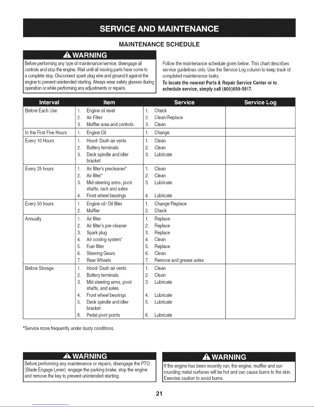
MAINTENANCE SCHEDULE
Beforeperforminganytypeofmaintenance/service,disengageall
controlsandstoptheengine.Waituntilallmovingpartshavecometo
acompletestop.Disconnectsparkplugwireandgrounditagainstthe
enginetopreventunintendedstarting.Alwayswearsafetyglassesduring
operationorwhileperforminganyadjustmentsor repairs.
BeforeEachUse
Inthe FirstFiveHours
Every10Hours
Every25 hours
Every50 hours
Annually
BeforeStorage
1. Engineoil level
2. Air Filter
3. Mufflerareaandcontrols
1. EngineOil
1. Hood/Dashairvents
2. Batteryterminals
3. Deckspindleandidler
bracket
1. Airfilter'sprecleaner*
2. Air filter*
3. Mid-steeringarms,pivot
shafts,rackandaxles
4. Frontwheelbearings
1. Engineoil/Oil filter
2. Muffler
1. Airfilter
2. Air filter'spre-cleaner
3. Sparkplug
4. Air coolingsystem*
5. Fuelfilter
6. SteeringGears
7. RearWheels
1. Hood/Dashairvents
2. Batteryterminals
3. Midsteeringarms,pivot
shafts,andaxles
4. Frontwheelbearings
5. Deckspindleandidler
bracket
6. Pedalpivotpoints
1. Check
2. Clean/Replace
3. Clean
1. Change
1. Clean
2. Clean
3. Lubricate
1. Clean
2. Clean
3. Lubricate
4. Lubricate
1. Change/Replace
2. Check
1. Replace
2. Replace
3. Replace
4. Clean
5. Replace
6. Clean
7. Removeandgreaseaxles
1. Clean
2. Clean
3. Lubricate
4. Lubricate
5. Lubricate
6. Lubricate
Followthe maintenanceschedulegivenbelow.Thischartdescribes
serviceguidelinesonly.Usethe ServiceLogcolumntokeeptrackof
completedmaintenancetasks.
Tolocate the nearest Parts& Repair Service Centeror to
scheduleservice,simplycall(800)659-5917.
*Servicemorefrequentlyunderdustyconditions.
Beforeperforminganymaintenanceor repairs,disengagethePTO
(BladeEngageLever),engagethe parkingbrake,stoptheengine
andremovethe keyto preventunintendedstarting.
If theenginehasbeenrecentlyrun,the engine,mufflerandsur-
roundingmetalsurfaceswillbehot andcancauseburnstotheskin.
Exercisecautiontoavoidburns.
21
Page 22
ENGINE MAINTENANCE
Shutoffthe enginebeforeperforminganymaintenance.Toprevent
accidentalstart-up,disconnectthe sparkplugboot.
iMPORTANT: if enginemustbetippedtotransportequipmentorto
inspector removegrass,keepsparkplugsideof engineup.Transport-
ingortippingenginesparkplugdownmaycausesmoking,hard
starting,sparkplugfouling,oroil saturationofaircleaner.
Periodicinspectionandadjustmentoftheengineisessentialifhigh
levelperformanceistobe maintained.Regularmaintenancewillalso
ensurealongservicelife.Therequiredserviceintervalsandthe kind
ofmaintenanceto beperformedaredescribedinthe tableonthe
previouspage.Followthehourlyor calendarintervals,whicheveroccur
first.Morefrequentserviceisrequiredwhenoperatinginadverse
conditions.
Ifthe enginehasbeenrunning,themufflerwillbeveryhot. Becareful
notto touchthemuffler.
Servicing the Engine Oil
• Checktheoil levelregularly.
• Besurecorrectoil levelismaintained.Checktheoil everyfiveto
tenhoursof operation,beforestartingtheengine.SeeChecking
Oil LevelintheAssemblysection.
Onlyuse highqualitydetergentoil ratedwithAPIserviceclassification
SF,SG,SH,or SJ.Selecttheoil'sSAEviscositygradeaccordingto
theexpectedoperatingtemperature.Referto Gas& Oilinthe As-
semblysectionofthismanual.
Oil Drain
8. Removetheoildrainsleevefromtheoilsump.Returnthedipstick
tothe oilfilltubeandscrewtheoilfill capbackintoplace.
9. Refilltheenginewiththenewmotoroil.Referto Gas& Oilinthe
Assemblysectionof thismanualforinformationregardingthe
approvedoiltype.
iMPORTANT: Usedmotoroil maycauseskincancerif repeatedly
left incontactwiththeskinforprolongedperiods.Althoughthis is
unlikelyunlessyouhandleusedoil ona dailybasis,it isstilladvis-
abletothoroughlywashyourhandswithsoapandwaterassoonas
possibleafterhandlingusedoil.
NOTE: Pleasedisposeofusedmotoroilina mannerthatiscompat-
iblewiththeenvironment.Wesuggestyoutakeitina sealedcontainer
toyour localservicestationfor reclamation.Donotthrowitinthe
trash,pourit downadrainoron the ground.
iMPORTANT: Besuretocheckengineonalevelsurfacewiththe
enginestopped.Draintheoilwhiletheengineis stillwarmtoassure
rapidandcompletedraining.
Fordrainingoilfromthe engine'scrankcaseofselectmodeltractors,a
plasticoildrainsleeveispackedwiththisOperator'sManual.Todrain
theoil, proceedasfollows:
1. Unscrewthe oilfill capand removethedipstickfromtheoil fill
tube.
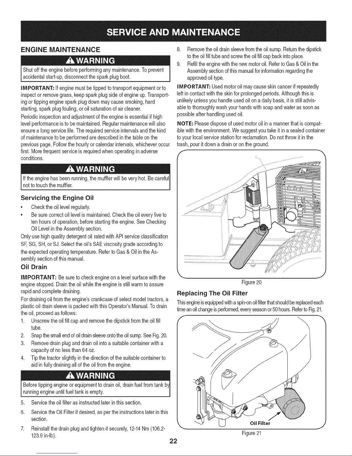
2. Snapthe smallendofoildrainsleeveontotheoilsump.SeeFig.20.
3. Removedrainpluganddrainoil intoa suitablecontainerwitha
capacityofno lessthan64oz.
4. Tipthe tractorslightlyinthe directionofthesuitablecontainerto
aidinfullydrainingall oftheoilfromtheengine.
Beforetippingengineor equipmentto drainoil,drainfuelfromtank
runningengineuntilfueltankisempty.
5. Servicetheoilfilteras instructedlater inthissection.
6. ServicetheOil Filterifdesired,aspertheinstructionslaterinthis
section.
7. Reinstallthedrainplugandtightenitsecurely,12-14Nm(106.2-
123.9in-lb).
Figure20
Replacing The Oil Filter
Thisengineisequippedwithaspin-onoilfilterthatshouldbereplacedeach
timeanoilchangeisperformed,everyseasonor50hours.RefertoFig.21.
_ 1/
OilFilter
Figure21
22
Page 23
ToreplacetheOilFilter:
1. Draintheoilasinstructionpreviouslyinthis section.
2. Removetheoil filter. Disposeofthe oldoil filterproperly.
3. Lubegasketofnewoil filterwithcleanoil.
4. Installandturnoilfilterbyhanduntilthegasketcomesincontactwith
thesealingsurfaceof thecrankcasecover,thentightentheoil
filter,10-12Nm(88.5-106.2in-lb),1/2-3/4turn.
5. Addoilas previouslyinstructed.
6. Makesuredipstickisinstalled.
7. Startandrunengine. Checkforleaks.
8. Stopengine. Waita fewminutesandcheckthe oil level. See
CheckingTheOil LevelintheAssemblysectionofthismanual.
Adding Oil
iMPORTANT: Besuretocheckengineon alevelsurfacewiththe
enginestopped.
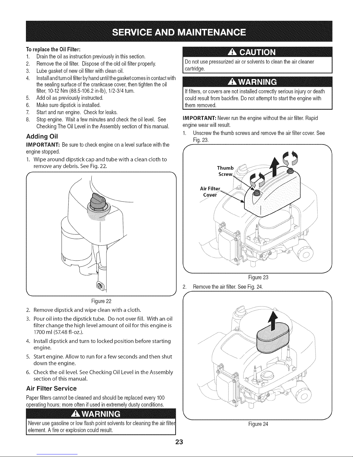
1. Wipe around dipstick cap and tube with a cleancloth to
remove any debris. SeeFig. 22.
Donot use _ressurizedairor solventstocleantheair cleaner
cartridge.
Iffilters,or coversarenotinstalledcorrectlyseriousinjuryordeath
couldresultfrombackfire.Donotattemptto starttheenginewith
themremoved.
IMPORTANT: Neverruntheenginewithouttheair filter.Rapid
enginewearwill result.
1. Unscrewthethumbscrewsand removetheairfiltercover.See
Fig.23.
Thumb
Screw
Air Filter
, '///
/
Figure 22
2. Remove dipstick and wipe clean with a cloth.
3. Pour oil into the dipstick tube. Do not over fill. With an oil
filter change the high level amount of oil for this engine is
1700 ml (57.48 fl-oz.).
4. Install dipstick and turn to locked position before starting
engine.
5. Start engine. Allow to run for afew seconds and then shut
down the engine.
6. Check the oil level. See Checking Oil Level in the Assembly
section of this manual.
Air Filter Service
Paperfilterscannotbecleanedandshouldbe replacedevery100
operatinghours;moreoftenif usedinextremelydustyconditions.
Neverusegasolineor lowflashpointsolventsforcleaningtheairfilter
element.Afire or explosioncould result.
23
Figure23
Removetheairfilter.SeeFig.24.
/
{ '_, ..................................../
Figure24
/ i
/
Page 24
.
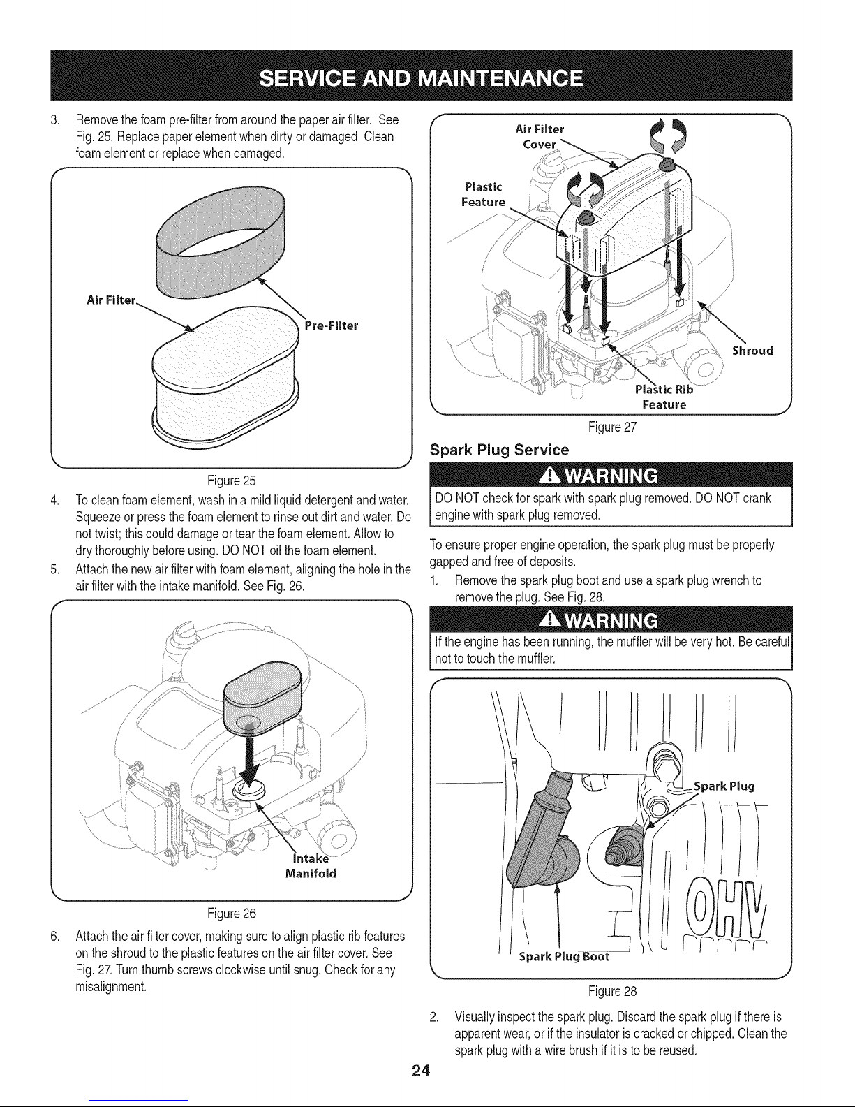
Removethefoampre-filterfromaroundthe paperair filter. See
Fig.25.Replacepaperelementwhendirtyor damaged.Clean
foamelementor replacewhendamaged.
Air Filter.
Figure25
4. Tocleanfoamelement,washina mildliquiddetergentandwater.
Squeezeor pressthefoamelementto rinseoutdirtandwater.Do
nottwist; thiscoulddamageortearthefoamelement.Allowto
drythoroughlybeforeusing.DO NOToilthe foamelement.
5. Attachthe newairfilterwithfoamelement,aligningtheholeinthe
airfilterwiththeintakemanifold.SeeFig.26.
Air Filter
Plastic
Feature
Shroud
)
Feature
Figure27
Spark Plug Service
DONOTcheckforsparkwith sparkplugremoved.DONOTcrank
enginewithsparkplugremoved.
Toensureproperengineoperation,the sparkplugmustbeproperly
gappedandfreeof deposits.
1. Removethesparkplugbootandusea sparkplugwrenchto
removethe plug.SeeFig.28.
Figure26
.
Attachtheair filtercover,makingsuretoalignplasticribfeatures
ontheshroudtothe plasticfeaturesontheair filtercover.See
Fig.27.Turnthumbscrewsclockwiseuntilsnug.Checkfor any
misalignment.
Iftheenginehas beenrunning,themufflerwillbeveryhot.Becareful
notto touchthemuffler.
SparkPlug
R.
Figure28
.
Visuallyinspectthe sparkplug.Discardthesparkplugifthereis
apparentwear,orif theinsulatoriscrackedorchipped.Cleanthe
sparkplugwitha wirebrushif it is tobe reused.
24
Page 25
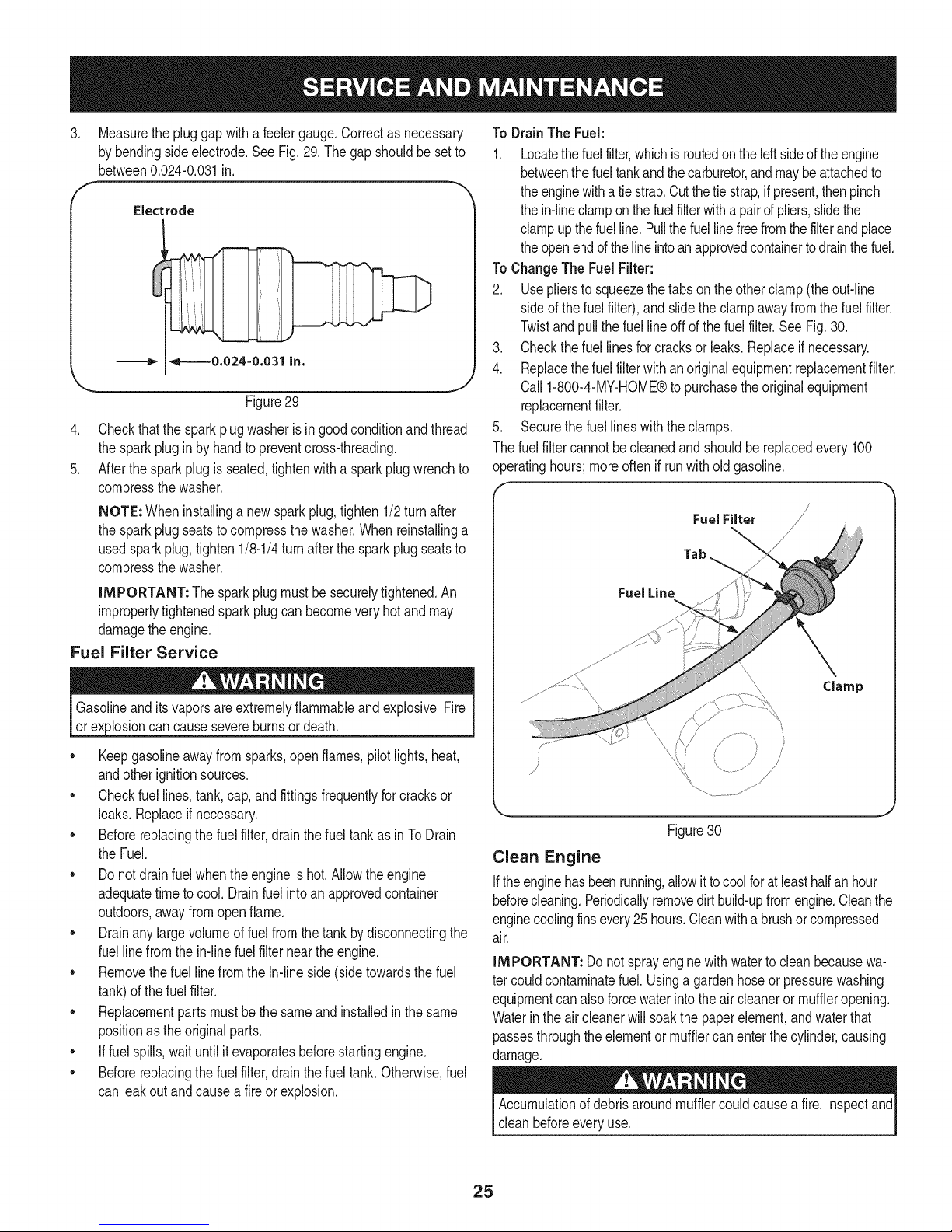
.
Measurethe pluggapwitha feelergauge.Correctas necessary
bybendingsideelectrode.SeeFig.29.Thegapshouldbesetto
between0.024-0.031in.
f
Electrode
Figure29
4.
Checkthatthe sparkplugwasheris ingoodconditionandthread
thesparkplugin byhandtopreventcross-threading.
5.
Afterthesparkplugis seated,tightenwithasparkplugwrenchto
compressthe washer.
NOTE: Wheninstallinga newsparkplug,tighten1/2turnafter
thesparkplugseatstocompressthewasher.Whenreinstallinga
usedsparkplug,tighten1/8-1/4turnafterthe sparkplugseatsto
compressthe washer.
IMPORTANT: The sparkplugmustbesecurelytightened.An
improperlytightenedsparkplugcan becomeveryhotandmay
damagetheengine.
Fuel Filter Service
To DrainThe Fuel:
1. Locatethefuelfilter,whichisroutedontheleftsideof theengine
betweenthefueltankandthecarburetor,andmaybeattachedto
theenginewithatie strap.Cutthetiestrap,ifpresent,thenpinch
thein-lineclamponthe fuelfilterwithapairofpliers,slidethe
clampupthefuelline.Pullthefuellinefreefromthefilterandplace
theopenendofthelineintoanapprovedcontainertodrainthefuel.
ToChangeThe FuelFilter:
2. Usepliersto squeezethetabson the otherclamp(theout-line
sideof thefuelfilter),and slidetheclampawayfromthefuelfilter.
Twistandpullthefuel lineoffof thefuelfilter.SeeFig.30.
3. Checkthefuellinesforcracksorleaks.Replaceifnecessary.
4. Replacethefuel filterwithanoriginalequipmentreplacementfilter.
Call1-800-4-MY-HOME®topurchasetheoriginalequipment
replacementfilter.
.
Securethefuellineswiththeclamps.
Thefuelfiltercannotbecleanedandshouldbe replacedevery100
operatinghours;moreoftenif runwitholdgasoline.
FuelFilter /
Tab
Fuel Line
Gasolineanditsvaporsareextremelyflammableandexplosive.Fire
or explosioncancausesevereburnsor death.
• Keepgasolineawayfromsparks,openflames,pilotlights,heat,
andotherignitionsources.
• Checkfuellines,tank,cap,andfittingsfrequentlyforcracksor
leaks.Replaceif necessary.
• Beforereplacingthe fuelfilter,drainthefueltankasinToDrain
theFuel.
• Donotdrainfuel whentheengineishot.Allowtheengine
adequatetimetocool. Drainfuelintoanapprovedcontainer
outdoors,awayfromopenflame.
• Drainanylargevolumeoffuelfromthe tankby disconnectingthe
fuellinefromthe in-linefuelfilterneartheengine.
• RemovethefuellinefromtheIn-lineside(sidetowardsthefuel
tank)ofthefuelfilter.
• Replacementpartsmustbethesameandinstalledinthesame
positionasthe originalparts.
• If fuelspills,waituntil itevaporatesbeforestartingengine.
• Beforereplacingthe fuelfilter,drainthefueltank.Otherwise,fuel
canleakoutand causea fireor explosion.
\
\
Figure30
Clean Engine
Iftheenginehasbeenrunning,allowit tocoolforatleasthalfanhour
beforecleaning.Periodicallyremovedirtbuild-upfromengine.Cleanthe
enginecoolingfinsevery25hours.Cleanwitha brushorcompressed
air.
IMPORTANT: Donotsprayenginewithwatertocleanbecausewa-
tercouldcontaminatefuel. Usinga gardenhoseorpressurewashing
equipmentcan alsoforcewaterintotheair cleanerormuffleropening.
Waterin theaircleanerwillsoakthepaperelement,andwaterthat
passesthroughthe elementormufflercanenterthecylinder,causing
damage.
Accumulationofdebrisaroundmufflercouldcausea fire.Inspectand
cleanbeforeeveryuse.
25
Page 26
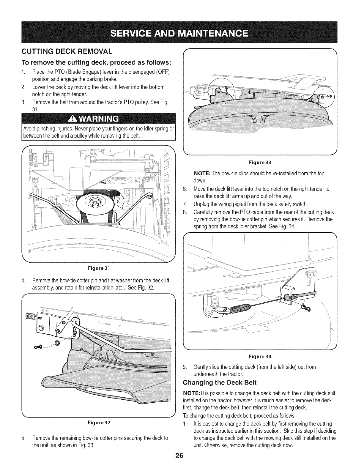
CUTTING DECK REMOVAL
To remove the cutting deck, proceed as follows:
1. Placethe PTO(BladeEngage)leverin the disengaged(OFF)
positionandengagetheparkingbrake.
2. Lowerthe deck bymovingthe deck lift lever intothe bottom
notchon therightfender.
3. Removethe beltfromaroundthetractor'sPTOpulley.SeeFig.
31.
Avoidpinchinginjuries.Neverplaceyourfingersontheidlerspringor
betweenthe beltanda pulleywhileremovingthebelt.
k,__ j
Figure 33
NOTE: Thebow-tieclipsshouldbe re-installedfromthetop
down.
.
Movethedecklift leverintothetopnotchon therightfenderto
raisethedecklift armsupandout oftheway.
7.
Unplugthewiringpigtailfromthedecksafetyswitch.
8.
CarefullyremovethePTOcablefromtherearof thecuttingdeck
by removingthe bow-tiecotterpinwhichsecuresit.Removethe
springfromthe deckidlerbracket.SeeFig.34.
F
Figure 31
4. Removethe bow-tiecotterpin andflat washerfromthe decklift
assembly,andretainfor reinstallationlater. SeeFig.32.
,._ j
Figure 32
5. Removethe remainingbow-tiecotterpinssecuringthedeckto
theunit,as shownin Fig.33.
Figure 34
9. Gentlyslidethecuttingdeck (fromtheleftside)outfrom
underneaththetractor.
Changing the Deck Belt
NOTE: Itispossibleto changethedeckbeltwiththecuttingdeckstill
installedonthetractor,howeveritis mucheasiertoremovethedeck
first,changethedeck belt,thenreinstallthecuttingdeck.
Tochangethecuttingdeckbelt,proceedasfollows:
1. Itiseasiesttochangethedeckbeltby firstremovingthe cutting
deckasinstructedearlierinthis section. Skipthisstepifdeciding
tochangethedeckbeltwiththemowingdeckstillinstalledonthe
unit.Otherwise,removethe cuttingdecknow.
26
Page 27
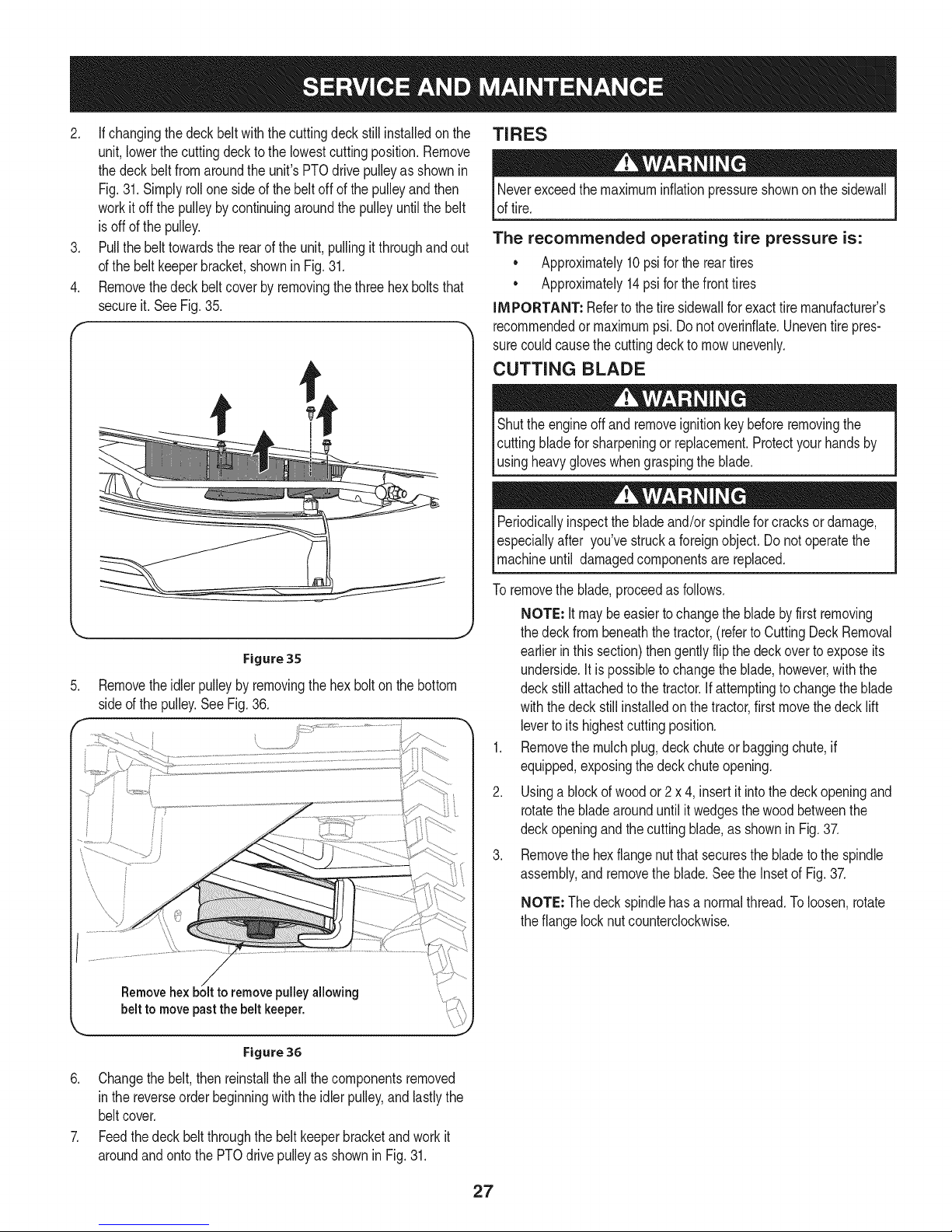
2. If changingthedeckbelt withthecuttingdeckstillinstalledonthe
unit,lowerthecuttingdeckto thelowestcuttingposition.Remove
thedeckbeltfromaroundtheunit'sPTOdrivepulleyasshownin
Fig.31.Simplyrollone sideofthebeltoff ofthepulleyandthen
workitoffthe pulleybycontinuingaroundthepulleyuntilthebelt
isoff ofthepulley.
3. Pullthebelttowardstherearoftheunit,pullingit throughandout
ofthe beltkeeperbracket,shownin Fig.31.
4. Removethedeckbeltcoverby removingthethreehexboltsthat
secureit. SeeFig.35.
f
TIRES
Neverexceedthe maximuminflationpressureshownonthesidewall
oftire.
The recommended operating tire pressure is:
• Approximately10psiforthe reartires
• Approximately14psi forthefronttires
IMPORTANT: Refertothetiresidewallfor exacttiremanufacturer's
recommendedormaximumpsi.Donotoverinfiate.Uneventirepres-
surecouldcausethecuttingdeckto mowunevenly.
CUTTING BLADE
Shutthe engineoff and removeignitionkeybeforeremovingthe
cuttingbladefor sharpeningor replacement.Protectyourhandsby
_usngheavygoveswhengraspngthe bade.
Periodicallyinspectthebladeand/orspindleforcracksor damage,
especiallyafter you'vestrucka foreignobject.Donotoperatethe
machineuntil damagedcomponentsarereplaced.
Figure 35
.
Removetheidlerpulleyby removingthehex boltonthebottom
sideof thepulley.SeeFig.36.
/
pulleyallowing
belt to move pastthe belt keeper.
Toremovetheblade,proceedasfollows.
NOTE: It maybeeasiertochangethebladebyfirstremoving
thedeckfrombeneaththetractor,(refertoCuttingDeckRemoval
earlierinthis section)thengentlyflipthedeckovertoexposeits
underside.Itispossibleto changetheblade,however,withthe
deckstillattachedto thetractor.Ifattemptingtochangetheblade
withthedeckstillinstalledonthetractor,firstmovethe decklift
levertoitshighestcuttingposition.
1. Removethemulchplug,deckchuteorbaggingchute,if
equipped,exposingthedeckchuteopening.
2. Usinga blockof woodor 2 x 4, insertit intothedeckopeningand
rotatethebladearounduntilit wedgesthewoodbetweenthe
deckopeningandthecuttingblade,as showninFig.37.
3. Removethehexflangenutthatsecuresthebladetothe spindle
assembly,and removetheblade.Seethe Insetof Fig.37.
NOTE: Thedeckspindlehasa normalthread.Toloosen,rotate
theflangelocknutcounterclockwise.
Figure 36
6. Changethebelt,thenreinstallthe allthe componentsremoved
in thereverseorderbeginningwith theidlerpulley,andlastlythe
beltcover.
7. Feedthedeck beltthroughthebeltkeeperbracketandworkit
aroundandontothe PTOdrivepulleyasshownin Fig.31.
27
Page 28
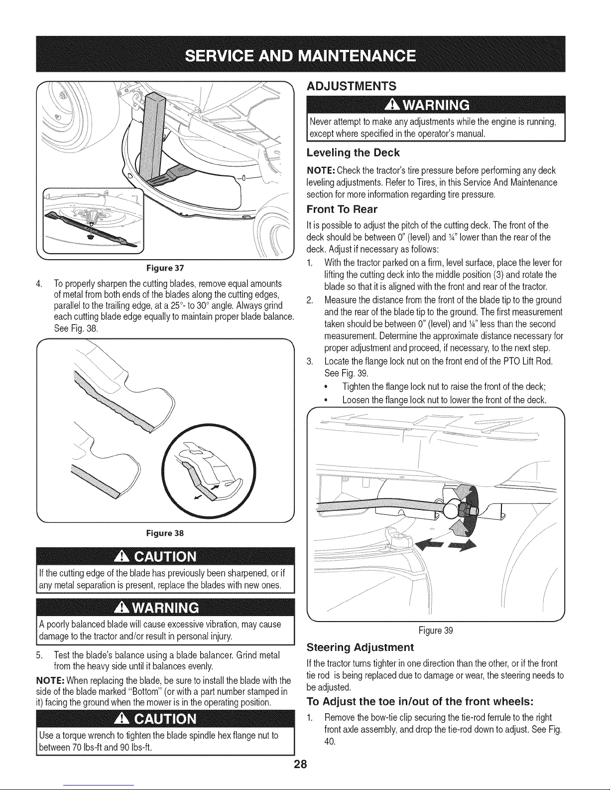
Figure 37
.
Toproperlysharpenthecuttingblades,removeequalamounts
ofmetalfrombothendsof thebladesalongthecuttingedges,
paralleltothe trailingedge,ata 250.to300angle.Alwaysgrind
eachcuttingbladeedgeequallyto maintainproperbladebalance.
SeeFig.38.
\
ADJUSTMENTS
Neverattemptto makeanyadjustmentswhilethe engineisrunning,
exceptwherespecifiedinthe operator'smanual.
Leveling the Deck
NOTE: Checkthetractor'stire pressurebeforeperforminganydeck
levelingadjustments.RefertoTires,inthis ServiceAndMaintenance
sectionfor moreinformationregardingtirepressure.
Front To Rear
Itis possibletoadjustthepitchofthe cuttingdeck.Thefrontof the
deckshouldbe between0"(level)andK" lowerthantherearof the
deck.Adjustif necessaryasfollows:
1. Withthetractorparkedona firm,levelsurface,placetheleverfor
liftingthecuttingdeckintothe middleposition(3)and rotatethe
bladesothatit is alignedwiththe frontand rearofthe tractor.
2. Measurethedistancefromthefrontof thebladetiptothe ground
andthe rearofthebladetip to theground.Thefirstmeasurement
takenshouldbebetween0"(level)andK" lessthanthesecond
measurement.Determinethe approximatedistancenecessaryfor
properadjustmentandproceed,if necessary,tothenextstep.
3. Locatetheflangelocknutonthe frontendof thePTOLift Rod.
See Fig.39.
• Tightentheflangelocknut toraisethefrontofthedeck;
• Loosentheflangelocknutto lowerthefrontof thedeck.
Figure 38
If thecuttingedgeofthebladehaspreviouslybeensharpened,or if
anymetalseparationispresent,replacethe bladeswithnewones.
A poorlybalancedbladewillcauseexcessivevibration,maycause
damagetothetractorand/orresultinpersonalinjury.
5. Testthe blade'sbalanceusinga bladebalancer.Grindmetal
fromtheheavysideuntilit balancesevenly.
NOTE: Whenreplacingtheblade,besureto installthe bladewiththe
sideof theblademarked"Bottom"(orwitha partnumberstampedin
it)facingthe groundwhenthemowerisin theoperatingposition.
Useatorquewrenchto tightenthebladespindlehexflangenutto
between70 Ibsiftand90 Ibsift.
J
/< j
//
Figure39
Steering Adjustment
Ifthetractorturnstighterinonedirectionthanthe other,or ifthe front
tie rod isbeingreplaceddueto damageorwear,thesteeringneedsto
be adjusted.
To Adjust the toe in/out of the front wheels:
1. Removethebow-tieclip securingthetie-rodferruletothe right
frontaxleassembly,anddropthetie-roddowntoadjust.See Fig.
40.
28
/ J
s//
i
Page 29
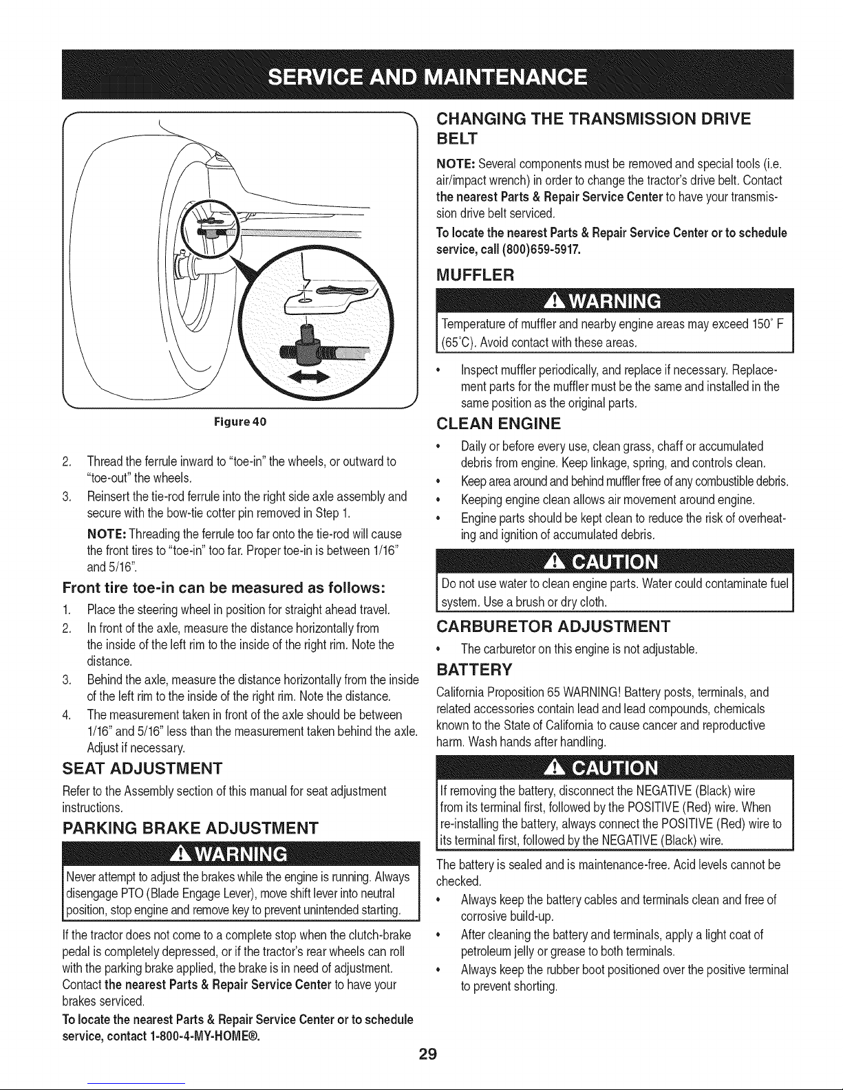
Figure 40
2. Threadtheferruleinwardto"toe-in"thewheels,oroutwardto
"toe-out"thewheels.
3. Reinsertthetie-rodferruleintothe rightsideaxleassemblyand
securewiththebow-tiecotterpinremovedin Step1.
NOTE: Threadingtheferruletoo farontothetie-rodwillcause
thefronttiresto "toe-in"too far.Propertoe-inis between1/16"
and5/16".
Front tire toe-in can be measured as follows:
1. Placethesteeringwheelin positionfor straightaheadtravel.
2. Infrontof the axle,measurethedistancehorizontallyfrom
theinsideofthe leftrim totheinsideofthe rightrim.Notethe
distance.
3. Behindtheaxle,measurethedistancehorizontallyfromthe inside
ofthe left rimto theinsideoftherightrim.Notethe distance.
4. Themeasurementtakeninfrontoftheaxle shouldbebetween
1/16"and5/16"lessthanthemeasurementtakenbehindthe axle.
Adjustif necessary.
SEAT ADJUSTMENT
Refertothe Assemblysectionofthismanualforseatadjustment
instructions.
PARKING BRAKE ADJUSTMENT
Neverattempttoadjustthe brakeswhiletheengineisrunning.Always
disengagePTO(BladeEngageLever),moveshiftleverintoneutral
position,stopengineandremovekeytopreventunintendedstarting.
If thetractordoesnotcometoacompletestopwhenthe clutch-brake
pedaliscompletelydepressed,orif thetractor'srearwheelscanroll
withtheparkingbrakeapplied,thebrakeisin needofadjustment.
Contactthe nearest Parts & Repair Service Center tohaveyour
brakesserviced.
Tolocate thenearest Parts&RepairServiceCenterortoschedule
service,contact1-800-4-MY-HOME®.
CHANGING THE TRANSMISSION DRIVE
BELT
NOTE: Severalcomponentsmustbe removedandspecialtools(i.e.
air/impactwrench)in ordertochangethetractor'sdrivebelt.Contact
the nearest Parts& RepairService Centertohaveyourtransmis-
siondrivebeltserviced.
Tolocatethe nearestParts& RepairServiceCenterorto schedule
service, call(800)659-5917.
MUFFLER
Temperatureof mufflerandnearbyengineareasmayexceed150°F
(65°0).Avoidcontactwiththeseareas.
• Inspectmufflerperiodically,andreplaceif necessary.Replace-
mentpartsforthe mufflermustbe thesameandinstalledinthe
samepositionastheoriginalparts.
CLEAN ENGINE
• Dailyor beforeeveryuse,cleangrass,chafforaccumulated
debrisfromengine.Keeplinkage,spring,andcontrolsclean.
• Keepareaaroundandbehindmufflerfreeofanycombustibledebris.
• Keepingenginecleanallowsair movementaroundengine.
• Enginepartsshouldbekeptcleanto reducetheriskofoverheat-
ingandignitionofaccumulateddebris.
Donot usewatertocleanengineparts.Watercouldcontaminatefuel
system.Usea brushordrycloth.
CARBURETOR ADJUSTMENT
• Thecarburetoron thisengineis notadjustable.
BATTERY
CaliforniaProposition65WARNING!Batteryposts,terminals,and
relatedaccessoriescontainleadandleadcompounds,chemicals
knownto the Stateof Californiatocausecancerandreproductive
harm.Washhandsafterhandling.
If removingthe battery,disconnecttheNEGATIVE(Black)wire
fromitsterminalfirst,followedbythe POSITIVE(Red)wire.When
re-installingthebattery,alwaysconnectthePOSITIVE(Red)wireto
[ts termna f rst,fo owedbytheNEGATVE (Back) wre.
Thebatteryissealedandismaintenance-free.Acidlevelscannotbe
checked.
• Alwayskeepthebatterycablesandterminalscleanandfreeof
corrosivebuild-up.
• Aftercleaningthebatteryandterminals,applyalightcoatof
petroleumjellyorgreasetobothterminals.
• Alwayskeepthe rubberbootpositionedoverthepositiveterminal
to preventshorting.
29
Page 30
iMPORTANT: if removingthe batteryforanyreason,disconnectthe
NEGATIVE(Black)wirefromitsterminalfirst,followedbythe POSI-
TIVE(Red)wire.When re-installingthebattery,alwaysconnectthe
POSITIVE(Red) wiretoitsterminalfirst,followedbythe NEGATIVE
(Black)wire.Becertainthatthewiresareconnectedtothe correct
terminals;reversingthemcouldchangethe polarityandresultin
damageto yourengine'salternatingsystem.
Cleaning Battery
Cleanthebatteryby removingitfromthetractorandwashingwith
a bakingsodaandwatersolution,ifnecessary,scrapethe battery
terminalswitha wirebrushto removedeposits.Coatterminalsand
exposedwiringwithgreaseor petroleumjelly to preventcorrosion.
Battery Failures
Somecommoncausesforbatteryfailureare:
• incorrectinitialactivation
• Overcharging
• Freezing
• Undercharging
• Corrodedconnections
Thesefailuresare NOTcoveredbyyourtractor'swarranty.
JUMP STARTING
Neverjump starta damagedorfrozenbattery.Becertainthevehicles
do nottouch,and ignitionsareoff. Do notallowcableclampsto
touch.
1. Connectpositive(+)cableto positivepost(+)ofyourtractor's
dischargedbattery.
2. Connecttheotherendof the cableto thepositive(+)postof the
jumperbattery.
3. Connectthe secondcablenegative(-) tothenegativepost(-) of
thejumper battery.
4. Connecttheotherendof the negativecabletothe engineblockof
thetractor,awayfromthe battery.Attachtoanunpaintedpartto
assurea goodconnection.
Ifthejumperbatteryis installedon avehicle(i.e.car,truck),do NOT
startthe vehicle'senginewhenjumpstartingyourtractor.
5. Startthetractor(as instructedintheOperationsectionofthis
manual).
6. Setthetractor'sparkingbrakebeforeremovingthejumpercables,
inreverseorderof connection.
CHARGING
Whenchargingyourtractor'sbattery,useonlyachargerdesignedfor I
12Vlead-acidbatteries.ReadyourbatterychargersOwners Manual
priortochargingyourtractorsbattery.Alwaysfollowits instructions I
land heed ts warnngs. j
Ifyourtractorhasnotbeenputintouseforan extendedperiodof time,
chargethe batteryasfollows:
1. Setyourbatterychargertodeliveramaxof10amperes.
Ifyourbatterychargeris automatic,chargethebatteryuntilthe
chargerindicatesthat chargingiscomplete.If thechargerisnot
automatic,chargefor nofewerthaneighthours.
FUSE
One15AMPfuseisinstalledinyourtractor'swiringharnesstoprotectthe
tractor'selectricalsystemfromdamagecausedbyexcessiveamperage.
Iftheelectricalsystemdoesnotfunction,oryour tractor'senginewill
notcrank;firstchecktobecertainthat thefusehasnotblown.Itcan
be foundunderthefenderontheleftsideof theunit,onthewiring
harnessjust abovethebattery.
Alwaysusea fusewith thesameamperagecapacityfor replacement.
LUBRICATION
Beforelubricating,repairing,or inspecting,alwaysdisengagePTO
(BladeEngageLever),moveshiftleverinto neutralposition,set
parkingbrake,stopengineandremovekeyto preventunintended
starting.
Pivot Points & Linkage
Lubricateall the pivotpointsonthe drivesystem,parkingbrakeandlift
linkageatleastoncea seasonwithlightoil.
Rear Wheels
Therearwheelsshouldberemovedfromthe axlesonce aseason.
Lubricatetheaxlesandtherimswellwithan all-purposegreasebefore
re-installingthem.
Front Axles
Eachendofthetractor'sfrontpivotbarmaybeequippedwitha grease
fitting.Lubricatewitha greasegunafterevery25hoursoftractoroperation.
Steering Rack & Pinion
Onceperseason,orevery25hoursof operation,itwillbenecessary
to lubricatethesteeringrackand piniongearlocatedunderthefrontof
theunit. Usingstandardautomotivegrease,applygreasetothefront
sideandrearsideofthe steeringrack,asindicatedin Fig.41.
off while the
in a wellventilatedareaand keepawayfromanopenflameor pilot I
lightas ona waterheater,spaceheater,furnace,clothesdryeror
lBatteriesgive an explosivegas charging.Charge batteryI
othergas app ances. 1
30
Page 31

© ©
Figure41
CLEANING THE ENGINE AND DECK
Anyfuel oroil spilledonthe machineshouldbewipedoffpromptly.Do
NOTallowdebristoaccumulatearoundtheenginecoolingfinsof the
engineoron anyotherpartofthemachine.
IMPORTANT: Theuseofa pressurewasherto cleanyourtractoris
NOTrecommended.It maycausedamagetoelectricalcomponents,
spindles,pulleys,bearingsor theengine.
Deck Wash System
Yourtractor'sdeckisequippedwitha waterportonits surfaceaspart
ofits deckwashsystem.
Usethedeckwashto rinsegrassclippingsfromthedeck'sunderside
andpreventthe buildupofcorrosivechemicals.Completethefollowing
stepsAFTEREACHMOWING:
1. Drivethetractortoa level,clearspotonyour lawn,nearenough
foryourgardenhoseto reach.
Makecertainthetractor'sdischargechuteis directedAWAYfromyour
house,garage,parkedcars,etc.
2. Disengagethe PTO(BladeEngage),setthe parkingbrakeand
stoptheengine.
3. Threadthehosecoupler(packagedwithyourtractor'sOperator's
Manual)ontotheendof yourgardenhose.
4. Attachthe hosecouplertothewaterport onyourdeck'ssurface.
SeeFig.42.
Figure42
5. Turnthewateron.
6. Whilesitting inthe operator'spositiononthe tractor,startthe
engineand placethethrottleleverin the FAST(rabbit)position.
7. Movethe tractor'sPTO(BladeEngage)intothe ONposition.
8. Remainin theoperator'spositionwiththecuttingdeckengaged
fora minimumoftwominutes,allowingtheundersideofthe
cuttingdeckto thoroughlyrinse.
9. Movethetractor'sPTO(BladeEngage)intotheOFFposition.
10. Turntheignitionkeyto the STOPpositiontoturnthetractor's
engineoff.
11. Turnthewateroffanddetachthehosecouplerfromthewater
portonyour deck'ssurface.
Aftercleaningyourdeck,returntothe operator'spositionandengage
thePTO.Keepthecuttingdeckrunningfor a minimumoftwo minutes,
allowingtheundersideofthecuttingdecktothoroughlydry.
31
Page 32

PREPARING THE ENGINE
Neverstorelawntractorwithfuel in tankindoorsorin poorly
ventilatedareaswherefuelfumesmayreachanopenflame,spark,
or pilotlightasona furnace,waterheater,clothesdryer,orgas
appliance.
iMPORTANT:Fuelleftinthefuel tankduringwarmweatherdeterio-
ratesandwillcauseseriousstartingproblems.
Failureto useafuelstabilizingadditiveorcompletelyrunthe engine
untilit'soutof fuel beforeoff-seasonstoragemayresultindamageto
yourengine'scarburetor.Subsequentdamagewouldnot becovered
underthe manufacturer'swarranty.
Enginesstoredbetween30 and90 daysneedtobetreatedwitha
gasolinestabilizerandenginesstoredover90 daysneedtobedrained
offuelto preventdeteriorationandgumfromformingin fuel systemor
onessentialcarburetorparts.Ifthe gasolineinyourenginedeterio-
ratesduringstorage,youmayneedto havethecarburetor,andother
fuelsystemcomponents,servicedorreplaced.
Topreventgumdepositsfromforminginsidetheengine'scarburetor
andcausingpossiblemalfunctionoftheengine,thefuel systemmust
beeithercompletelyemptied,or thegasolinemustbetreatedwitha
stabilizertopreventdeterioration.
1. If usingafuelstabilizer:
a. Readthe productmanufacturer'sinstructionsandrecom-
mendations.
b. Addtoclean,freshgasolinethecorrectamountof stabilizer
forthe capacityofthefuel system.
c. Fillthefuel tankwithtreatedfueland runtheenginefor2-3
minutestogetstabilizedfuel intothecarburetor.
2. If emptyingthefuelsystem:
a. Donotdrainfuelwhentheengineishot.Allowtheengine
adequatetimetocool. Drainfuelintoanapprovedcontainer
outdoors,awayfromopenflame.
b. Drainanylargevolumeoffuelfromthetankbydisconnect-
ingthefuel linefromthein-linefuelfilterneartheengine.
SeethecompleteinstructionsforDrainingThe Fuellaterin
thissection.
Gasolineisextremelyflammableandcanbeexplosiveundercertain
conditions.Draingasolinebeforestoringtheequipmentforextended
periods.Drainfuelonlyintoan approvedcontaineroutdoors,away
fromanopenflame.Allowenginetocool.Extinguishcigarettes,
cigars,pipes,andothersourcesof ignitionpriortodrainingfuel.
Storegasolinein anapprovedcontainerin safelocation.
Gasolineisa toxicsubstance.Disposeofgasolineproperly.Contact
yourlocal authoritiesforapproveddisposalmethods.
3. Removethesparkplugandpourone(1)ounceof engineoil
throughthesparkplugholeintothecylinder.Cranktheengine
severaltimes todistributetheoil. Replacethe sparkplug.
4. Cleandebrisfromaroundengine,underfingerguard,andunder,
aroundandbehindmuffler.Touchupany damagedpaint,and
coatotherareasthatmayrustwitha light filmofoil.
5. Storeina clean,dryandwellventilatedareaawayfromanyap-
pliancethatoperateswitha flameor pilotlight,suchasafurnace,
waterheater,or clothesdryer.Alsoavoidanyareawitha spark
producingelectricmotor,or wherepowertoolsareoperated.
6. If possible,alsoavoidstorageareaswithhighhumidity,because
thatpromotesrustandcorrosion.
7. Keeptheenginelevelin storage.Tiltingcancausefuel oroil
leakage.
DRAINING THE FUEL
1. Locatethefuelfilter,whichislocatedon theleftsideof the
engine,andmaybeattachedto theenginewitha tie strap.
2. Cutthetie strap,ifpresent,thenpinch thein-lineclampon the
fuelfilterwitha pairofpliers,slidethe clampup thefuel line.
3. Pullthefuel linefree fromthefilterandplacethe openendof the
lineintoan approvedcontainerto drainthefuel.
PREPARING THE LAWN TRACTOR
1. Cleanandlubricatetheunit thoroughlyasdescribedinthe
LubricationinstructionsintheServiceandMaintenancesection.
2. Donot usea pressurewasherorgardenhoseto cleanyourunit.
3. Storemowerina dry,cleanarea.Donotstorenexttocorrosive
materials,suchas fertilizer.
Removing From Storage
1. ChecktheoillevelasdescribedintheAssemblysectionofthis
manual.
2. If thefuelwasdrainedduringstoragepreparation,fillthe tankwith
freshgasoline.If youkeepa containerofgasolinefor refueling,
makecertainitcontainsonlyfreshfuel.Gasolineoxidizesand
deterioratesovertime,causinghardstarting.
3. If thecylinderwascoatedwithoil duringstoragepreparation,the
enginewillsmokebrieflyat startup.Thisisnormal.
c. Reconnectthefuellineand runtheengineuntilit startsto
falter,thenusethe choketokeepthe enginerunninguntilall
fuelinthe carburetorhasbeenexhausted.
d. Disconnectthefuel lineanddrainanyremaininggasoline
fromthe system.
32
Page 33

Enginefailstostart
1. PTO/BladeEngageleverengaged.
2. Parkingbrakenotengaged.
3. Sparkplugwire(s)disconnected.
4. Throttle/ChokecontroJlevernotincorrect
1. Placeleverindisengaged(OFF)position.
2. Engageparkingbrake.
3. Connectwire(s)tosparkplug(s).
4. PlaceThrottle/ChokeleverintotheFASTposition.
startingposition.
Enginerunserratically
5. Chokenotactivated
6. Fueltankempty,orstalefuel.
7. Blockedfuelline.
8. Faultysparkplug(s).
9. Engineflooded.
10.BlownFuse(s).
11.Safetyswitch(s)notproperlyengaged.
1. UnitrunningwithCHOKEactivated.
2. Sparkplugwire(s)loose.
3. Blockedfuellineorstalefuel.
4. Ventingascapplugged.
5. Waterordirtinfuelsystem.
6. Dirtyaircleaner.
5. MovetheThrottle/ChokeleverintotheChoke
6. Filltankwithclean,fresh(lessthan30daysold)gas.
7. Replacethefuellineandreplacefuelfilter.
8. Clean,adjustgaporreplaceplug(s).
9. CrankenginewiththrottleinFASTposition.
10.ReplaceFuse(s)
11.Ensureseatisintheproperoperatingposition,and/
1. DeactivatetheCHOKE.
2. Connectsparkplugwire(s).
3. Replacethefuelline;filltankwithclean,fresh
4. Clearventorreplacecapifdamaged.
5. Drainfueltank.Refillwithclean,freshgasoline.
6. Replaceaircleanerpaperelementorcleanfoam
Engineoverheats 1. Engineoillevellow. 1.
2. Airflowrestricted. 2.
EnginehesitatesathighRPM 1. Sparkpluggaptooclose. 1.
Engineidlesrough 1. Sparkplugfouled,faultyorgaptoowide. 1.
2. Dirtyaircleaner. 2.
Excessivevibration
Mowerwillnotmulchgrass
Unevencut
1. Cuttingbladelooseorunbalanced.
2. Damagedorbentcuttingblade.
1. Enginespeedtoolow.
2. Wetgrass.
3. Excessivelyhighgrass.
4. Dullblade.
1. Decknotleveledproperly.
2. Dullblade.
3. Uneventirepressure.
1. Tightenbladeandspindle.
2. Replaceblade.
1. PlacethrottleinFAST(rabbit)position.
2. Donotmulchwhengrassiswet.
3. Mowonceatahighcuttingheight,thenmowagain
4. Sharpenorreplaceblade.
1. Performside-to-sidedeckadjustment.
2. Sharpenorreplaceblade.
3. Checktirepressureinallfourtires.
position.
ordeckchute,tubeormulchplugproperlyinstalled.
gasolineandreplacefuelfilter.
pre-cleaner,ifequipped.
Fillcrankcasewithproperamountandweightofoil.
Cleangrassclippingsanddebrisfromaroundthe
engine'scoolingfinsandhousing.
Removesparkplugandresetthegap.
Replacesparkplug.Setpluggap.
Replaceaircleanerelementand/orcleanpre-
cleaner.
atdesiredheightormakeanarrowercuttingswath.
Find this and a{[ your other product manuals online.
6et answers from our team of home experts,
Get a personalized maintenance ptan for your home,
Find information and tools to help with home projects.
bzo_#_tteye_ #y S_s_
33
Page 34

777123510 777D17063
TOP VIEW
777S34102
777D16808
Centered On Steering Column
777D17041
Operators Left Side
AJign To Top Edge
777D17040
Operators Right Side
Align To "lop Edge
777S34202
Place On Top Of Deck
On The Lower Ridge
Keep Off Curves
777S34201
Place On Top Of Deck
Keep Off Curves
777D17060
Center On Rear
Engine Cover
REF: Chute Labe!
Applied By Manufacturer
777D17037
Place On Front Of Deck
34
Page 35

Craftsman Model 247.25000
24
\
\12
35
Page 36

Craftsman Model 247.25000
Ref, [
No,
1 710-0924
2 710-1241
3 710-3008
4 710-3015
5 712-04063
6 712-04064
7 712-04092
8 731-08813
9 731-08814
10 731-08815
11 731-08816
12 738-04184A
13 749-04932-0637
14 783-07208-0637
15 710-1652
16 731-08528
17 731-08753
18 936-0463
19 683-04751-0637
20 783-07125
21 783-07162-0637
22 783-07168-0637
23 783-07215-0637
24 783-07302
25 683-04767-0637
Part No. Description
Machine Screw, 1/4-20, 0.750
Hex Screw, 1/4-15, 1.000
Hex Head Screw, 5/16-18, .75
Hex Head Screw, 1/4-20, .75
Flange Locknut, 5/16-18
Flange Locknut, 1/4-20
U-type Speed Nut, 1/4-20
Column Cover
Steering Column Cap
Fender
Rear Cover
Shoulder Screw, .368 X.113:1/4-20
Rear Cover Support Tube
Hitch Plate
Tap Screw, 1/4-20, .625
Running Board
Running Board Plug
Flat Washer, .250 x .630 x .052
Frame Assembly
Deck Lift Index Bracket
Seat Pan
Seat Pivot Bracket
Battery Tray
Top Rear Drive Cover
Bumper
36
Page 37

Craftsman IViodel 247.25000
37
Page 38

Craftsman Model 247.25000
Ref, [
No,
1 918-05056
2 647-04262
3 683-04768-0637
4 683-04779
5 710-04484
6 710-05378
7 710-05415A
8 710-0599
9 710-0623
I0 710-0757
II 710-0809
12 710-1007
13 710-1325
14 710-1652
15 711-0736
16 712-04065
17 712-0700
18 914-0209
19 714-04040
20 718-04407
21 720-04028
22 732-0459C
23 732-04934
24 936-0171
25 736-0322
26 736-3010
27 738-0372B
Part No, Description
Transmission Assembly
Shift Handle Assembly
Drive Assembly Idler
Variable Bracket Assembly
Tap Screw, 5/16-18, .750
Tap Screw, 5/16-18, 2.50
Hex Head Scew, 3/8-16, 1.62
Tap Scew, 1/4-20, 0.500
Tap Screw, 3/8-16, 0.750
Hex Head Screw, 7/16-20, 1.50
Tap Screw, 1/4-20, 1.250
SEMS Tap Screw, 3/8-16, 1.500
Tap Screw, 1/4-20, 1.625
Tap Screw, 1/4-20 x .625
Adjustable Ferrule, 1/4-20 X 1.00
Flange Lock Nut, 3/8-16
Flange Nut, 9/16-18
Internal Cotter Pin, .125 Dia.
Bow-Tie Cotter Pin
Pulley Hub, 5/8 Spline
Shift Knob
Extension Spring, .94 Dia. X 6.74 Lg.
Extension Spring, .97 OD X 6.18
Split Lock Washer, 7/16
Flat Washer, .450X1.250X.164
Flat Washer, .407X.812X.135
Shoulder Spacer, 1.00 X .38 X .38
Ref, I
NO,
28 738-0930
29 747-05593
30 747-05617A
31 950-04099
32 750-04456
33 750-3119
34 954-0241A
35 954-04331
36 756-04224
37 756-04325
38 756-04464
39 756-04479
40 783-07207
41 783-07248
42 956-04015A
43 N/A
44 710-0627
45 710-0778
46 718-04261
47 736-0362
48 941-0600
49 934-0139-0911
50 734-04641
51 634-04319-4042
52 934-0255
53 710-0627
54
Part No, Description
Shoulder Spacer, .560x.165, 5/16-18
Shift Rod
Deck Belt Keeper, 30"
Stepped Spacer, .265 ID X .750
Spacer, .260 X .372 X 1.420
Spacer, .406 ID X 1.00 OD X .38
V-Belt, 5L:35.25
V-Belt, 5L:35.28
Flat Idler Pulley, 2.75 OD
V-Type Idler Pulley, 3.06
V-Type Pulley, 6.56
Engine Pulley, 4.46 / 3.39
Front Support Shift Bracket
Rear Idler Arm Bracket
Variable Speed Pulley Assembly
Variable Bracket (order 683-04779)
Hex Head Lock Screw, 5/16-24:.750
Tap Screw, 1/4-20:1.500
Bearing Cup
Flat Washer, .330x1.250x.060
Ball Bearing, 17 X40X 12
Complete Wheel Assembly
Tire, 16 x 6.5 x 8 Sq. Shldr.
Rim Assembly, 8.0 x 5.38
Air Valve
Hex Head Screw, 5/16-24, 7.50
38
Page 39

Craftsman IViodel 247.25000
11
®
22
34
34
2O
39
Page 40

Craftsman IViodel 247.25000
Ref, I
No,
1 710-0607
2 712-04063
3 720-04009A
4 732-04905
5 735-0271A
6 938-0140
7 757-04158
8 783-07213-0637
9 683-04754-0637
10 712-04065
11 720-04049A
12 725-0157
13 732-04956
14 738-04554
15 946-04802
16 735-04081
17 751-12118
18 951-04366
19 951-12179A
20 925-1707D
21 710-0227
22 710-1652
23 712-04064
24 725-04363
25 725-04439
26 925-04659
27 925-05013
28 725-1643
29 925-1745A
30 926-0320
31 738-04237A
32 783-07384-0637
33 738-1132
34 712-0271
-- 925-05359
Part No. Description
TapScrew,5/16-18,0.500
FlangeLockNut,5/16-18
Knob,3/8-16,.875
SeatSpring
Bumper,.62DIAX .3
ShoulderSpacer,.435X .178-5/16X .56
Seat
SeatPivotBracket
PTOHandleAssembly
FlangeLockNut,3/8-16
HandleGrip,3/8
CableTie,3/16X .05X 7.4
ExtensionSpring,.50OD X4.646LG
ShoulderBolt,.500X .270:3/8-16
PTOCable
RubberGrommet
RolloverValve
FuelTank,1-3Gal.
FuelCap
Battery,155CCA
Screw,#8
TapScrew,1/4-20,.625
FlangeLockNut,1/4-20
InterlockSwitch
Solienoid,12v
Three-WayKeySwitch
SeatSwitch
SwitchSpring
Key
InsulatorPlate
ShoulderScrew,#10-32,.500
BatteryHold-DownBracket
Screw,Shoulder,.250x .150
Nut,Sems,1/4-20
WiringHarness(NotShown)
4O
Page 41

Craftsman IViodel 247.25000
15\
12
41
Page 42

Craftsman Model 247.25000
Ref, [
No,
1 683-04699-0637
2 910-0224
3 710-0376
4 710-04484
5 710-3008
6 911-04075A
7 711-0736
8 712-04063
9 914-0111
10 714-04040
11 726-0214
12 731-08656
13 731-08743
14 732-04937
15 732-0716D
16 735-04279
17 936-0264
18 736-3072
19 738-04184A
20 741-0356A
21 747-05506
22 747-05508
23 747-05616
24 748-0234
25 783-05940
26 783-07050-0637
27 783-07287
28 717-0772B
Part No, Description
Brake Pedal Assembly
Screw, #10-16:0.500
Hex Head Scerw, 5/16-18:1.00
Tap Screw, 5/16-18:.750
Hex Head Screw, 5/16-18:.75
Ferrule 3/8-24 X .375 Dia.
Adjustable Ferrule, 1/4-20 X 1.00
Flange Lock Nut, 5/16-18
Cotter Pin, 3/32Xl .0
Bow-Tie Cotter Pin, 72
Push Cap, 5/8
Speed Control Cover
Speed Lever, 6-SPEED
Shift Spring
Extension Spring, .59 OD X 4.00 LG
Foot Pad, 2.5" LG.
Flat Washer, .330x.630x.064
Flat Washer, .380X.930X.110
Shoulder Screw, .368 X.113, 1/4-20
Steering Col. Bearing, .880 ID X 1.36
Variable Speed Control Rod
Brake Rod
Speed Selector Control Rod
Shoulder Spacer
Pedal Strap Support Bracket, 5/8
Speed Latch Bracket
Brake Cam Bracket
Brake lever Bracket
42
Page 43

Craftsman Model 247.25000
_32 \31
12
\29
31
14
21 ©
21\_
29
9
43
Page 44

Craftsman Model 247.25000
I
Ref.
I Part No.
1 683-04726-0637
2 683-04727-0637
3 683-04761
4 683-04762
5 710-05046
6 710-05386
7 710-0643
8 710-0703
9 711-04448
10 712-04064
II 712-04065
12 714-04040
13 717-1554
14 726-0341
15 726-04127
16 731-08690
17 731-08691
18 736-0242
19 738-04537
20 741-04542
21 741-0660A
22 747-05514
23 747-05585
24 747-05686
25 783-06988
26 783-07239
27 631-04008A
28 731-06825
29 634-04726
30 736-04228A
31 714-0162
32 931-0484A
Description
Front Axle Assembly, RH
Front Axle Assembly, LH
Upper Tube Assembly
Lower Tube Assembly
Allen Wrench, 3/16
Screw, 1/4-20 X 1.25
Hex Head Screw, 5/16-18:1.00
Carriage Screw, 1/4-20, .75
Ferrule, 5/16-24 X .312 Dia.
Flange Lock Nut, 1/4-20
Flange Lock Nut, 3/8-16
Bow-Tie Cotter Pin, 72
Steering Pinion Gear
Push Cap, 3/4
Snap Butt
Lower Steering Collar
Upper Steering Collar
Bevel Washer, .340X.872X.060
Steering Shaft, .625 OD X 18.03
Hex Flange Bearing, 5/8
Flange Bearing, .760 X .941 X 1.0
Steering Rod, LH
Steering Rod, RH
Front Tie Rod
Steering Rack Plate
Lower Steering Bearing
Steering Wheel
Steering Cap
Complete Wheel Assembly
Washer, .781 x 1.59
Cotter Pin, 5/32 x 1.25
Hub Cap
44
Page 45

Craftsman IViodel 247.25000
11
45
Page 46

Craftsman Model 247.25000
|
Ref.
I Part No.
1 683-04706-0637
2 683-04757-0637
3 710-04484
4 710-0514
5 710-0642
6 710-0809
7 710-1652
8 711-05690
9 712-04065
10 712-04243
II 714-04040
12 714-04043
13 720-0311
14 732-04692
15 936-0300
16 938-0347
17 747-05511
18 747-05576-0637
19 750-0566A
20 783-07129-0637
Description
Lift Assembly Shaft
Front Hanger Bracket Assembly
Tap Screw, 5/16-18, .750
Hex Head Screw, 3/8-16, 1.00
Tap Screw, 1/4-20, 0.750
Tap Screw, 1/4-20, 1.250
Tap Screw, 1/4-20 X .625
Ferrule, .50 X .50
Flange Lock Nut, 3/8-16
Flex Lock Nut, 1/2-13
Bow-Tie Cotter Pin, 72
Bow-Tie Cotter Pin, 91
Grip Handle, 1/2
Extension Spring, .85 OD X 5.915 LG
Flat Washer, .406 X .875 X .059
Shoulder Spacer, .625 ID X .169
Lift Link Rod
Deck Lift Rod
Spacer, .260 x .375 x 1.030 LG
Front Deck Mounting Bracket
46
Page 47

Craftsman Model 247.25000
iT-1
9
\6
2
47
Page 48

Craftsman Model 247.25000
I
Ref.
I Part No.
1 710-04483
2 710-04683
3 71O-O5446
4 726-0205
5 731-1682A
6 946-04829
7 751-10349
8 aBS-298090S
9 952Z4P90JUA
Description
Tap Screw, 1/4-20, 0.500
Tap Screw, 3/8-16, 1.000
Tap Screw, 3/8-16, 2.250
Hose Clamp, .490 DIA.
Oil Drain Sleeve
Throttle/Choke Cable 31 Lg.
Low Permeation Fuel Line, 1/4
Fuel Filter, 1/4", 298090
Replacement Engine (4P90JUA)
48
Page 49

Craftsman Model 247.25000
[]
22
&\38
12
49
Page 50

Craftsman IViodel 247.25000
Ref, I
No,
1 918-04822A
2 683-04734
3 683-04782-0637
4 710-04484
5 710-04998
6 710-0514
7 710-0778
8 710-I026
9 710-1315
10 710-1652
II 712-04065
12 712-0417A
13 714-04040
14 720-04122
15 726-0201
16 731-07487
17 732-04948A
18 732-0814
19 936-0289
20 736-0362
21 736-0518
22 783-07342-0637
23 938-0347
Part No, Description
Spindle Pulley Assembly, 6.3 DIA
PTO Brake Assembly Bracket
Rear Deck Assembly Bracket
Tap Screw, 5/16-18, .750
Carriage Screw, 5/16-18, 1.00
Hex Head Screw, 3/8-16, 1.00
Tap Screw, 1/4-20, 1.500
Tap Screw, 1/4-20, 1.750
Tap Screw, 3/8-16, 1.250
Tap Screw, 1/4-20 X .625
Flange Lock Nut, 3/8-16
Flange Nut, 5/8-18
Bow-Tie Cotter Pin, 72
Wing Knob, 5/16-18
Speed Nut, .3125 ID
Deck Wash Nozzle
Ext. Spring, .708 X 7.357 X .094
Ext. Spring, .56 OD X 5.52 LG
Shoulder Bushing, .320 ID X .135
Flat Washer, .330x1.250x.060
Thrust Washer, .445X.1.920X.060
Deck Belt Cover
Shoulder Spacer, .625 ID X .169
Ref, I
No,
24 738-04162A
25 738-04278
26 942-04385
27 750-04456
28 750-0566A
29 954-04318
30 756-04224
31 783-07004
32 783-07146-0637
33 783-07184-0637
34 783-07204-0637
35 783-07304
36 783-07306
37 631-04633
38 738-04519
39 712-0417A
40 936-0351
41 738-I186A
42 941-0919A
43 750-04936
44 956-1227
45 946-04802
Part No, Description
Shoulder Spacer, .8840 X .190
Shoulder Spacer, 1/4-20, 0.50
Cutting Blade, 30.00" 3-1N-1
Spacer, .260 X .372 X 1.420 LG
Spacer, .260 x .375 x 1.030 LG
V-Type Belt, 5L,45.15 LG
Flat Idler Pulley, 2.75 OD
Front Deck Bracket
Deck, 30" w/Nozzle
RR Deck Bracket, LH
Release Brake Bracket
Lower Floating Idler Bracket
Upper Floating Idler Bracket
Chute Deflector
Shoulder Screw, 1/4-15 x .750
Flange Nut, 5/8-18
Shim Washer, .760X1.500X.030
Spindle Shaft, 6.11 LG.
Ball Bearing, .7871D X 1.85 ODX.551
Spacer, .792 X 1.060 X 1.860 LG
Deck Pulley, 6.3 DIA
PTO Cable
5O
Page 51

Craftsman Engine Model 4P90JUA For Model 247.25000
120
127-_o_ 01128
]
0
1 126
m
120
121
122
124
126
127
128
129
130
130 _1 127
129
951-12255
712-04291
951-12255
951-12256
951-12260
712-04212
951-12328
951-12257
951-12258
D = " O
Air FilterCoverAssembly
Air FilterLockNut
Air FilterCover
SpongeFilter
Air FilterAssembly
NutM6
RubberCap
Manifold
ManifoldGasket
51
Page 52

Craftsman Engine IViodel 4P90JUA For IViodel 247.25000
_2
m
2
3
4
5
6
7
1
192
751-12205
712-04290
750-05320
710-05304
951-11622
710-05305
951-12206
710-05303
7
D = O O
DebrisShield
Nut
EngineShroudSpacer
Starter/ShroudStud M6xlO0
FlexibleClamp
HookBolt
Air Shield
Self-TappingBolt5.5x25
52
Page 53

Craftsman Engine IViodel 4P90JUA For IViodel 247.25000
1_5-U
_183
197-GasketI{it-Complete
198-GasketI{it-External
199-CompleteEagiae
51--_
°__53
_47
189
I
7O
55
I
178
67
53
Page 54

Craftsman Engine IViodel 4P90JUA For IViodel 247.25000
m
47
48
49
5O
51
52
53
54
55
56
57
58
59
6O
62
63
64
65
66
67
68
951-11499
710-04916
751-12770
951-12226
951-12685
951-12227
951-12686
951-12228
951-12229
736-04558
714-04074
951-11574
951-12230
951-12231
951-12232
710-04908
712-04212
951-12233
710-04979
710-05310
951-12234
D = 0
UpperCrankshaftSeal
BoltM6x14
BreatherCoverPlate
BreatherGasket
UmbrellaValve
MeshScreen
UmbrellaValveSeat
ChokeLinkage
GovernorArmShaft
GovernorWasher
GovernorCotterPin
GovernorSeal
ThrottleLinkage
ThrottleLinkageSpring
GovernorArm
GovernorArmBolt
GovernorArmNutM6
GovernorSpring
BoltM6x18
BoltM6x38
ThrottleControlBracket
m
69
7O
72
73
m
74
178
183
184
185
186
189
197
198
199
750-05530
951-12235
951-12236
751-12200A
951-12237
951-12275
951-11953
951-12276
951-11954
951-12277
710-05319
951-12204
951-12201
952Z4P90JUA
m = 0
ComponentBracketSpacer
BreatherHoseAssembly
BreatherHoseClamp
ShortBlockAssembly
(Incl.37,47-53,55-58,73-77,84,
86-89,91-93,98-104,112,113,
115-119,137,138,144,160,172,
173,175-178,183-186)
CrankcaseCoverGasket
PistonRingSet
PistonPinSnapRing
Piston
PistonPin
ConnectingRodAssembly
ConnectingRodBolt
GasketKit- Complete
(Incl.47,50,58,74,113,118,
130,136-138,144,160,166)
GasketKit- External
(Inc1.113,130,136-138,144,160)
CompleteEngine(4PgOJUA)
54
Page 55

Craftsman Engine Model 4P90JUA For Model 247.25000
197-GasketKit- Complete
198-GasketKit- External
153 155 _
152
151-_O
151-_O
1A_ 147 148 149
147 148 149
142
154 157
155 16_i_
145
199-CompleteEngine
163
150
163
173
175
174
175
174
162 (_
173
193--_)
I
194
I
OPTIONAL
142
@--142
55
140
141
I,--14o
_140
Page 56

Craftsman Engine IViodel 4P90JUA For IViodel 247.25000
m
140
141
142
143
144
145
146
147
148
149
150
151
152
153
154
155
157
162
163
164
165
710-05315
951-12265
710-05316
951-12266
951-12267
951-11981
751-11124
751-11123
951-11966
710-04962
951-12268
951-12081
951-12080
951-12078
951-11964
951-12077
951-11337
951-10292
710-05317
710-05318
751-12778
D = O 0
BoltM5xlO
Cowl
ValveCoverBolt
ValveCover
ValveCoverRingGasket
RockerArmAssembly
Jam Nut
FulcrumNut
RockerArm
RockerArmStud
PushRodGuide
ExhaustValveAdjuster
ExhaustValveSpringRetainer
ValveSpring
intakeValveSeal
ValveSpringRetainer
ValveKit
SparkPlug/F6Rtc
BoltM10x1.25x85
Bolt/M10x1.25x65
CylinderHeadAsm
(Incl.137-139,144,146-157,
160,161,163-172)
m
165
166
167
168
169
170
171
172
173
174
175
176
177
193
194
196
197
198
199
951-12202
751-12774
751-12775
751-12776
751-12777
736-04629
710-05450
951-12273
715-04122
951-11335
951-11962
736-04561
951-12274
951-12329
710-05344
951-12197
951-12204
951-12201
952Z4P90JU
D = W O
CylinderHead Kit
(Inc1.144,156,163,164,166)
Air ValveCore
StrainerClip
Strainer
TheAirValveBonnet
Washer
ScrewM5x12
CylinderHeadGasket
CylinderHead Dowel12x16
PushRodKit
Tappet
CamshaftThrustWasher
CamshaftAssembly
SparkArrestor
SparkArrestorScrew
ValveCoverKit
GasketKit- Complete
(Incl.47,50,58,74,113,118,
130,136-138,144,160,166)
GasketKit- External
(Inc1.113,130,136-138,144,160)
CompleteEngine
56
Page 57

Craftsman Engine Model 4P90JUA For Model 247.25000
76--_
--75
79_ -8{
82_ 3
_----91
_---93
84--_
104
116
114
117
57
Page 58

Craftsman Engine IViodel 4P90JUA For IViodel 247.25000
m
5
75
76
77
79
8O
81
82
83
84
85
86
87
88
89
9O
91
92
93
951-11622
951-12238
951-11969
951-10307
951-12239
951-12241
951-12363
951-12240
710-04980
710-05311
951-12242
715-04121
951-12243
951-12244
710-05312
736-04557
951-12245
751-12246
736-04559
D = O O
FlexibleClamp
CrankshaftAssembly
MainBearing
WoodruffKey
DipstickAssembly
UpperO-Ring
LowerO-Ring
Oil FillTubeAssembly
BoltM6x35
Oil DrainPlug
Regulator
DowelPin8x14
Ball6.35
Spring
Bolt
CrankshaftThrustWasher
BalanceableShaftBearing
BalanceableShaftAssembly
BalanceableThrustWasher
m
98
99
1CO
101
102
103
104
112
113
114
115
116
117
118
119
195
951-12248
951-12247
951-12249
951-12250
951-12251
951-12252
951-11956
710-05313
736-04560
951-12690
951-12253
951-12254
951-12318
710-04982
951-11375
710-05314
951-12194
D = O O
OilPumpAssembly
O-Ring10x2.65
Filter
FilterSpring
O-Ring35.5x2.65
FilterCover
GovernorGear/ShaftAssembly
BoltM8x15
OilDrainPlugWasher
Oil Filter
ScrewJoint
CrankcaseCover
CrankcaseCoverAsm
(Incl.87-89,100-104,112,113,115,116)
BoltM8x54
LowerCrankshaftSeal
BoltM8x43
OilDrainPlugAssembly
58
Page 59

Craftsman Engine Model 4P90JUA For Model 247.25000
134
134
137
--133
139139 138
200-CarburetorI(it- Major
F A
o _ __
BB
CC
59
Page 60

Craftsman Engine Model 4P90JUA For Model 247.25000
m
131
132
133
134
136
137
138
139
200
A
B
C
D
E
F
G
H
I
J
K
951-12823
951-11731
951-11336
723-04071
951-12261
951-12262
951-12263
951-12264
751-12779
n/a
n/a
n/a
n/a
n/a
n/a
n/a
n/a
n/a
n/a
n/a
m = I! O
CarburetorAssembly
FuelHoseClamp
FuelLineKit
PlasticSupportClamp
CarburetorGasket
CarburetorInsulator
CarburetorInsulatorGasket
CarbStud
CarburetorKit- Major
(Inck130,136,B,BB,CC,DD,G,
M,N,U,W,Y,Z)
ChokeShaft
FiberO-Ring
ChokeReturnSpring
FlatSteelWasher
ChokePlate
Idle,JetAssembly
IdleJet O-Ring
SheetmetalHousing
ThrottleShaft
ThrottlePlate
ScrewM3x5
L
M
N
0
P
Q
R
S
T
U
V
W
X
Y
Z
AA
BB
CC
DD
EE
GG
HH
n/a
n/a
n/a
n/a
n/a
n/a
n/a
n/a
n/a
n/a
n/a
n/a
n/a
951-12304
751-12772
751-12773
n/a
951-11349
710-04938
710-05449
736-04554
710-05337
D = I! O
LockWasher
Nylon/PlasticO-Ring
FiberO-Ring
IdleSpeedAdjustingScrew
IdleMixtureScrew
CarburetorBody
FuelInlet
FloatPin
EmulsionTube
NeedleValve
MainJet
NeedleValveSpring
Float
FuelBowlO-Ring
Seat/FuelBowlBoltO-Ring
SolenoidValveAssembly
FuelBowl
FuelDrainPlugGasket
FuelDrainPlug
Seat!FuelBowlBolt
Washer
ScrewM5x12
6O
Page 61

Craftsman Engine Model 4P90JUA For Model 247.25000
m
48
158
159
160
161
161
190
191
190--
710-04916
712-04219
951-12270
951-12271
951-12272
951-12196
951-12278
710-05051
48
161
161
D = O O
BoltM6x14
NutM8
MufflerAssembly
ExhaustPipeGasket
MuffStud M8x47
MufflerStudAssembly
WireMeshShield
BoltM6x12
61
Page 62

Craftsman Engine Model 4P90JUA For Model 247.25000
8
I
10
11--o | o--ll
23
25---o
24--W \_
24
I
25
_-14
37
37
_--17
m
8
9
10
11
12
13
14
15
16
17
18
19
21
710-05306
951-12207
710-05307
736-04554
736-04556
951-12208
951-12211
951-12210
951-12312
951-12209
951-12212
951-12214
951-12216
I = O
BoltM8x40
StarterAssembly
ScrewM5x25
LockWasher5
PlainWasher6
ElectricalStarterFrontCover
Bearing
Pinion/ClutchAssembly
Gear
Bearing
PinionCover
Bearing6001Zz
Bearing
m
23
24
25
28
29
30
31
33
34
35
36
37
951-12528
951-12217
736-04554
951-12529
951-12219
710-05308
951-12324
736-04555
736-04556
736-04477
712-04212
715-04120
m = O O
StarterHousingAssembly
Screw
LockWasher
Brush Assembly
ElectricalStarterBackCover
BoltM6xl00
BoltM6x30Assembly
InsulationWasher
PlainWasher6
LockWasher6
NutM6
DowelPin 10x14
62
Page 63

Craftsman Engine IViodel 4P90JUA For IViodel 247.25000
m
38
39
4O
41
42
43
44
45
46
38
710-04920
951-12220
712-04220
951-12221
751-12222A
951-12223
951-12224
710-04940
951-12279
m43
38-
45
D = O O
BoltM6x28
IgnitionCoil Assembly
FlywheelNutM16x1.5
FanMountingPlate
CoolingFan
Flywheel
CoilAssy.Charge
BoltM6xlO
Cowl
63
Page 64

Look For Relevant Emissions Durability Period and
Air index information On Your Engine Emissions Label
Engines that are certified to meet the California Air Resources Board (CARB) Tier 2 Emission Standards must
display information regarding the Emissions Durability Period and the Air Index. Sears Brands Management
Corporation makes this information available to the consumer on our emission labels.
The Emissions Durability Period describes the number of hours of actual running time for which the engine is
certified to be emissions compliant, assuming proper maintenance in accordance with the Operating & Mainte-
nance Instructions. The following categories are used:
Moderate: Engine is certified to be emission compliant for 125 hours of actual engine running time.
Intermediate: Engine is certified to be emission compliant for 250 hours of actual engine running time.
Extended: Engine is certified to be emission compliant for 500 hours of actual engine running time.
For example, a typical walk-behind lawn mower is used 20 to 25 hours per year. Therefore, the Emissions
Durability Period of an engine with an intermediate rating would equate to 10 to 12 years.
The Air index is a calculated number describing the relative level of emissions for a specific engine family. The
lower the Air Index, the cleaner the engine. This information is displayed in graphical form on the emissions label.
After July 1,2000, Look For Emissions Compliance Period
On Engine Emissions Compliance Label
After July 1, 2000 certain Sears Brands Management Corporation engines will be certified to meet the United
States Environmental Protection Agency (USEPA) Phase 2 emission standards. For Phase 2 certified engines, the
Emissions Compliance Period referred to on the Emissions Compliance label indicates the number of operating
hours for which the engine has been shown to meet Federal emission requirements.
For engines less than 225 cc displacement, Category C = 125 hours, B = 250 hours and A = 500 hours.
For engines of 225 cc or more, Category C = 250 hours, B = 500 hours and A = 1000 hours.
This isa generic representation of the emission label typically found on a certified engine.
FAMILYYBSXS.3192VA 274812
GDOC-100182Rev.B
64
Page 65

(Thispageapplicableinthe U.S.A.andCanadaonly.)
Sears Brands Management Corporation (Sears), the California Air Resources Board (CARD)
and the United States Environmental Protection Agency (U.S. EPA)
Emission Control System Warranty Statement (Owner's Defect Warranty Rights and Obligations)
EMISSIONCONTROLWARRANTYCOVERAGEISAPPLICABLETOCERTI-
FIEDENGINESPURCHASEDINCALIFORNIAIN1995ANDTHEREAF-
TER,WHICHAREUSEDINCALIFORNIA,ANDTOCERTIFIEDMODEL
California and United States Emission
TheCaliforniaAirResourcesBoard(CARD),U.S.EPAandSearsare pleased
toexplainthe EmissionControlSystemWarrantyonyour modelyear2000and
latersmalloff-roadengine(SORE).InCalifornia,newsmalloff-roadengines
mustbe designed,builtandequippedto meettheState'sstringentanti-smog
standards.Elsewherein theUnitedStates,newnon-road,spark-ignition
enginescertifiedformodelyear1997and latermustmeetsimilarstandardsset
forthbythe U.S.EPA.Sears mustwarranttheemissioncontrolsystemonyour
YEAR1997ANDLATERENGINESWHICHAREPURCHASEDANDUSED
ELSEWHEREINTHEUNITEDSTATES(ANDAFTERJANUARY1,2001 IN
CANADA).
Control Defects Warranty Statement
enginefortheperiodsoftime listedbelow,providedtherehasbeennoabuse,
neglector impropermaintenanceofyour smalloff-roadengine.Youremis-
sioncontrolsystemincludespartssuchasthecarburetor,aircleaner,ignition
system,mufflerandcatalyticconverter.Also includedmaybeconnectorsand
otheremissionrelatedassemblies.Wherea warrantableconditionexists,Sears
will repairyoursmalloff-roadengineatnocostto youincludingdiagnosis,parts
andlabor.
Sears Emission Control Defects Warranty Coverage
Smalloff-roadenginesarewarrantedrelativeto emissioncontrolpartsdefects
fora periodofoneyear,subjecttoprovisionsset forthbelow.Ifanycovered
Owner's Warranty
Asthe smalloff-roadengineowner,youareresponsiblefor theperformanceof
therequiredmaintenancelistedin yourOperatingandMaintenanceInstruc-
tions.Searsrecommendsthatyouretainallyourreceiptscoveringmaintenance
onyoursmalloff-roadengine,butSearscannotdenywarrantysolelyforthe
lackofreceiptsorfor yourfailuretoensuretheperformanceof allscheduled
maintenance.As the smalloff-roadengineowner,youshouldhoweverbe
awarethatSearsmaydenyyouwarrantycoverageifyour smalloff-roadengine
ora parthasfaileddueto abuse,neglect,impropermaintenanceor unap-
parton yourengineis defective,the partwillbe repairedorreplacedbySears.
Responsibilities
provedmodifications.Youareresponsibleforpresentingyoursmalloff-road
engineto an AuthorizedSearsServiceDealeras soonasa problemexists.The
undisputedwarrantyrepairsshouldbecompletedina reasonableamountof
time,notto exceed30days.Ifyouhaveanyquestionsregardingyourwarranty
rightsandresponsibilities,youshouldcontacta SearsServiceRepresentative
at 1-800-469-4663.Theemissionwarrantyisa defectswarranty.Defectsare
judgedonnormalengineperformance.Thewarrantyis notrelatedtoan in-use
emissiontest.
Sears Emission Control Defects Warranty Provisions
ThefollowingarespecificprovisionsrelativetoyourEmissionControlDefectsWarrantyCoverage.ItisinadditiontotheSearsenginewarrantyfornon-regulated
enginesfoundin theOperatingand MaintenanceInstructions.
1. WarrantedParts
Coverageunderthis warrantyextendsonlytothe partslistedbelow(the
emissioncontrolsystemsparts)tothe extentthese partswere presenton
theenginepurchased.
a. FuelMeteringSystem
• Cold start enrichmentsystem
• Carburetorand internalparts
• FuelPump
b. AirlnductionSystem
• Air cleaner
• Intakemanifold
c. IgnitionSystem
• Sparkplug(s)
• Magnetoignitionsystem
d. CatalystSystem
• Catalyticconverter
• Exhaustmanifold
• Air injectionsystemorpulsevalve
e. MiscellaneousItemsUsedin AboveSystems
• Vacuum,temperature,position,timesensitivevalves
andswitches
• Connectorsandassemblies
2. LengthofCoverage
Searswarrantsto the initialownerand eachsubsequentpurchaserthat
theWarrantedPartsshallbefree fromdefectsin materialsandworkman-
shipwhich causedthefailureof the WarrantedPartsfor a periodofone
yearfromthe datethe engineis deliveredtoa retailpurchaser.
Inthe USAandCanada,a 24hourhotline, 1-800-469-4663,has amenuofpre-recordedmessagesofferingyouenginemaintenanceinformation.
3. NoCharge
RepairorreplacementofanyWarrantedPartwill beperformedat no
chargeto the owner,includingdiagnosticlaborwhichleadsto the
determinationthata WarrantedPartisdefective,ifthe diagnosticworkis
performedatanAuthorizedSearsServiceDealer.Foremissionswarranty
servicecontact yournearestAuthorizedSearsServiceDealeras listed in
the "YellowPages"under"Engines,Gasoline,""GasolineEngines,""Lawn
Mowers,"orsimilarcategory.
4. Claimsand CoverageExclusions
Warrantyclaimsshallbefiled in accordancewiththe provisionsof the
SearsEngineWarrantyPolicy.Warrantycoverageshallbeexcludedfor
failuresof WarrantedPartswhicharenotoriginalSearspartsorbecause
ofabuse,neglector impropermaintenanceassetforthinthe Sears
EngineWarrantyPolicy.Searsisnotliableto coverfailuresof Warranted
Partscausedby theuseof add-on,non-original,ormodifiedparts.
5. Maintenance
AnyWarrantedPartwhichis notscheduledforreplacementasrequired
maintenanceor whichis scheduledonlyfor regularinspectionto the effect
of"repairor replaceasnecessary"shallbe warrantedastodefectsfor the
warrantyperiod.AnyWarrantedPartwhichisscheduledfor replacement
asrequiredmaintenanceshallbewarrantedas to defectsonlyforthe
periodoftime upto the firstscheduledreplacementfor that part.Any
replacementpart that isequivalentinperformanceand durabilitymay
beusedinthe performanceofanymaintenanceorrepairs.Theowneris
responsibleforthe performanceof all requiredmaintenance,as definedin
the SearsOperatingand MaintenanceInstructions.
6. ConsequentialCoverage
Coveragehereundershallextendto thefailureofanyenginecomponents
causedbythefailureofany WarrantedPartstillunderwarranty.
GDOC-100188Rev.B
65
Page 66

FEDERAL and/or CALIFORNIA EMISSION CONTROL WARRANTY STATEMENT
YOUR WARRANTY RIGHTS AND OBLIGATIONS
MTDConsumerGroupInc,theUnitedStatesEnvironmentalProtectionAgency(EPA),and,forthoseproductscertifiedforsale in the stateofCalifornia,the
CaliforniaAirResourcesBoard(CARB)are pleasedtoexplainthe emission(evaporativeand/orexhaust)controlsystem(ECS)warrantyon youroutdoor2006
andlater smalloff-roadspark-ignitedengineandequipment(outdoorequipmentengine)InCalifornia,newoutdoorequipmentenginesmustbedesigned,builtand
equippedtomeetthe State'sstringentanti-smogstandards(inotherstates,1997andlater modelyear equipmentmustbedesigned,built,and equippedto meet
theU.S.EPAsmalloff-road,sparkignitionengineregulations.MTDConsumerGroupIncmustwarrantthe ECSonyouroutdoorequipmentengineforthe periodof
timelistedbelowprovidedtherehasbeen noabuse,neglector impropermaintenanceofoutdoorequipmentengine.
YourECSmayincludepartssuchas thecarburetor,fuel-injectionsystem,the ignitionsystem,catalyticconverter,fueltanks,fuel lines,fuelcaps,valves,canisters,
filters,vaporhoses,clamps,connectors,andotherassociatedemission-relatedcomponents.
Wherea warrantableconditionexists,MTDConsumerGroupIncwill repairyouroutdoorequipmentengineat nocost toyouincludingdiagnosis,partsand labor.
MANUFACTURER'S WARRANTY COVERAGE:
Thisemissioncontrolsystemiswarrantedfortwo years.If anyemission-relatedpartonyouroutdoorequipmentengineisdefective,the partwill berepairedor
replacedby MTDCONSUMERGROUPINC.
OWNER'S WARRANTY RESPONSIBILITIES:
Asthe outdoorequipmentengineowner,youareresponsiblefor performanceofthe requiredmaintenancelisted inyourowner'smanual.MTDConsumerGroup
Increcommendsthatyou retainallreceiptscoveringmaintenanceon youroutdoorequipmentengine,butMTDConsumerGroupInccannotdenywarrantysolely
forthe lackof receipts.
Asthe outdoorequipmentengineowner,youshouldhoweverbe awarethat MTDConsumerGroupInc maydenyyouwarrantycoverageifyour outdoorequipment
engineor a parthasfaileddue to abuse,neglect,or impropermaintenanceor unapprovedmodifications.
Youare responsibleforpresentingyouroutdoorequipmentengineto MTDConsumerGroupInc'sdistributioncenterorservicecenteras soon asthe problem
exists.Thewarrantyrepairsshouldbecompletedin a reasonableamountoftime, nottoexceed30 days.Ifyouhaveaquestionregardingyourwarrantycoverage,
youshouldcontacttheMTDConsumerGroupIncServiceDepartmentat 1-800-800-7310orvia emailat http://support.mtdproducts.com
GENERAL EMISSIONS WARRANTY COVERAGE:
MTDConsumerGroupIncwarrantstothe ultimatepurchaserandeachsubsequentpurchaserthat theoutdoorequipmentengineis: Designed,builtandequipped
soasto conformwithall applicableregulations;andfreefromdefectsin materialsand workmanshipthatcausethe failureof a warrantedparttobe identicalinall
materialrespectstothatpartas describedin MTDConsumerGroupInc'sapplicationforcertification.
Thewarrantyperiodbeginsonthedatetheoutdoorequipmentengineisdeliveredto anultimatepurchaserorfirst placedinto service.The warrantyperiodistwo
years.
Subjecttocertainconditionsandexclusionsasstatedbelow,the warrantyonemission-relatedparts is asfollows:
1. Any warrantedpartthatis notscheduledfor replacementasrequiredmaintenancein thewritteninstructionssupplied,iswarrantedforthe warrantyperiod
statedabove.Ifthepartfails duringthe periodofwarrantycoverage,thepart will berepairedor replacedbyMTDConsumerGroupIncaccordingto subsection
(4)below.Anysuchpart repairedor replacedunderwarrantywillbewarrantedforthe remainderof the period.
2. Any warrantedpartthatis scheduledonlyforregularinspectionin the writteninstructionssuppliediswarrantedforthe warrantyperiodstatedabove.Any such
partrepairedor replacedunderwarrantywill bewarrantedforthe remainingwarrantyperiod.
3. Any warrantedpartthatis scheduledforreplacementasrequiredmaintenanceinthewritten instructionssuppliediswarrantedforthe periodof timebeforethe
firstscheduledreplacementdateforthat part.If the partfailsbeforethefirst scheduledreplacement,the partwill berepairedorreplacedby MTDConsumer
GroupIncaccordingto subsection(4)below.Anysuchpartrepairedor replacedunderwarrantywillbewarrantedforthe remainderofthe periodpriortothe
firstscheduledreplacementpointforthe part.
4. Repairor replacementofany warrantedpart underthewarrantyprovisionshereinmustbeperformedata warrantystationatno chargetothe owner.
5. Notwithstandingthe provisionsherein,warrantyservicesor repairswill beprovidedat allof our distributioncentersthatarefranchisedto servicethesubject
enginesor equipment.
6. The outdoorequipmentengineownerwill notbe chargedfordiagnosticlaborthat is directlyassociatedwithdiagnosisof a defective,emission-relatedwar-
rantedpart, providedthatsuchdiagnosticworkis performedata warrantystation.
7. MTDConsumerGroupIncis liablefor damagesto otherengineor equipmentcomponentsproximatelycausedby afailureunderwarrantyof any warranted
part.
8. Throughouttheoff-roadengineand equipmentwarrantyperiodstatedabove,MTDConsumerGroupIncwill maintainasupplyof warrantedpartssufficientto
meetthe expecteddemandfor suchparts.
9. Any replacementpartmaybe usedinthe performanceof anywarrantymaintenanceor repairsand mustbeprovidedwithoutchargeto the owner.Suchusewill
notreducethe warrantyobligationsofMTDConsumerGroupInc.
10.Add-onor modifiedpartsthat are notexemptedbythe AirResourcesBoardmaynot beused.Theuseofany non-exemptedadd-onor modifiedpartsbythe
ultimatepurchaserwillbegroundsfor disallowinga warrantyclaims.MTDConsumerGroupIncwillnotbeliableto warrantfailuresof warrantedpartscaused
bythe useofa non-exemptedadd-onor modifiedpart.
Page 67

WARRANTED PARTS:
Therepairor replacementof anywarrantedpart otherwiseeligiblefor warrantycoveragemaybe excludedfromsuchwarrantycoverageifMTDConsumerGroup
Incdemonstratesthatthe outdoorequipmentenginehasbeenabused,neglected,orimproperlymaintained,andthat suchabuse,neglect,orimpropermainte-
nancewasthe directcauseof the needforrepairor replacementofthe part.Thatnotwithstanding,anyadjustmentof a componentthat hasa factoryinstalled,
andproperlyoperating,adjustmentlimitingdeviceisstill eligiblefor warrantycoverage.Further,thecoverageunderthiswarrantyextendsonlyto partsthat were
presentonthe off-roadengineand equipmentpurchased.
Thefollowingemissionwarrantypartsarecovered(ifapplicable):
(1)FuelMeteringSystem
• Cold startenrichmentsystem(softchoke)
• Carburetorand internalparts(orfuel injectionsystem)
• Fuelpump
• Fueltank
(2)Air InductionSystem
• Aircleaner
• Intakemanifold
(3) IgnitionSystem
• Sparkplug(s)
• Magnetoignitionsystem
(4) ExhaustSystem
• Catalyticconverter
• SAI(Reedvalve)
(5) MiscellaneousItemsUsedin AboveSystem
• Vacuum,temperature,position,timesensitivevalvesandswitches
• Connectorsandassemblies
(6) EvaporativeControl
• Fuelhose
• Fuelhoseclamps
• Tetheredfuel cap
• Carboncanister
• Vapor lines
GDOC-100223Rev.A
Page 68

Congratulations on making a smart purchase. Your new Craftsman® product is designed and
manufactured for years of dependable operation. But like all products, it may require repair
from time to time. That's when having a Repair Protection Agreement can save you money and
aggravation.
Here's what the Repair Protection Agreement* includes:
[] Expert service by our 10,000 professional repair specialists
[] Unlimited service and no charge for parts and labor on all covered repairs
[] Product replacement up to $1500 if your covered product can't be fixed
[] Discount of 25% from regular price of service and related installed parts not covered by the
agreement; also, 25% off regular price of preventive maintenance check
[] Fast help by phone - we call it Rapid Resolution - phone support from a Sears representative.
Think of us as a "talking owner's manual."
Once you purchase the Repair Protection Agreement, a simple phone call is all that it takes for you
to schedule service. You can call anytime day or night, or schedule a service appointment online.
The Repair Protection Agreement is a risk-free purchase. If you cancel for any reason during the
product warranty period, we will provide a full refund. Or, a prorated refund anytime after the
product warranty period expires. Purchase your Repair Protection Agreement today!
Some limitations and exclusions apply. For prices and additional information in the U.S.A.
call 1=800=827=6655.
*Coverage in Canada varies on some items. For full details call Sears Canada at 1=800=361=
6665.
Sears Installation Service
For Sears professional installation of home appliances, garage door openers, water heaters, and
other major home items, in the U.S.A. or Canada call 1=800=4=MY=HOME®.
68
Page 69

Operaci6n segura Pr,_cticas .......... Paginas 70 Soluci6n de problemas ............... Page 100
Asamblea ........................... Page 77 Lista de piezas ..................... Paginas 35
Operaci6n de ...................... Paginas 82 Reparaci6n de Acuerdo de Protecci6n ... Page 107
De Servicio y Mantenimiento de ....... Paginas 88 Servicio de nOmeros ............ atrasados Page
Fuera de temporada de almacenamiento .. Page 99
CRAFTSMAN GARANTiA TOTAL
PORDOSANOSa partirdelafechadecornpra,todaslaspartesnofungiblesdeesteequipodeequitaci6nest_ngarantizadoscontracualquierdefectode
materialo rnanodeobra.Unapiezadefectuosanofungiblesrecibir_.nreparaci6ngratuitaenelhogaro lasustituci6nsilareparaci6nesirnposible.
DURANTECINCOANOSdesdelafechadecornpra,elejedelmarcoy elfrentedeesteequipodeequitacbnest_ngarantizadoscontracualquierdefectode
materialo rnanodeobra.Uncuadrodefectuosooejedelanterorecibir_reparacbngratuitaenelhogarolasustitucbnsilareparacbnesirnposible.
POR90 DIASapartrdelafechadecornpra,labateria(unapartefungibles)deesteequipodeequitaci6nest_garantizadacontracualquierdefectode
materialo rnanodeobra(nuestraspruebasdernuestraquenornantienelacarga).Unabateriadefectuosarecibir_,reernplazogratuitoenelhogar.
ADICIONALDEGARANTiALIMITADADEPORVIDAenFUNDICIONejedelantero(si est;_instalado)
PARASIEMPREYCOMOSEUTILIZAporelpropietariooriginaldespu_sdelquintoa_odesdelafechadecornpra,elhierrofundidoejedelantero(siexiste)
deesteequipodeequitacbnest_garantizadacontracualquierdefectodematerialornanodeobra.Conelcornprobantedecornpra,unejedelanterofundido
defectuosorecibir_reernplazogratuitoenelhogar.
GARANTiADESERVICIO
Paraobtenerinforrnaci6ndetaladacoberturadelagarantaparaobtenerlareparaci6no sustituci6ngratuita,Ilarneal1-800-659-5917ovisiteel sitioweb:
www.craftsrnan.corn
Entodosloscasosanteriores,si lareparaci6no reernplazodeunaparteesirnposible,elequipodeequitacbnser_.reernplazadodeformagratuitaconel
rnisrnoo equivalente.
Todoslosdelacoberturadelagarantaanterioresinv&lidasiesteequipodernontaracabaloesutlizadoalgunavez,rnientrasquelaprestacbndeservicios
cornercialeso sisealqulaaotrapersona.
Estagarantacubrelos defectosSOLOdernaterialesyfabricacibn.Lagarantanoincluye:
• Laspartesconsurnibles(exceptolabateria)quepuedegastarseporelusonormaldentrodelperiododegaranta,incluyendoperonolrnitadoa,cuchllas,
bujias,fltrosdeaire,correasyfltrosdeaceite.
• Losserviciosdemantenimiento,cambiosdeaceite,o puestasa punto.
•Tireelreernplazooreparacbndepinchazoscausadospotobjetosexternos,talescornoclavos,espinas,toconesovidrio.
•Tiredelaruedao elreernplazoo lareparaci6nresutantesdeldesgastenormal,accidenteornalfuncionarnientoo rnantenirniento.
• Lasreparacionesnecesariasdebidoalabusodeloperador,incluyendoperonolrnitadoalosdaSoscausadosporelrernolquedelosobjetosrn&sall&dela
capacidaddelequipodeequitaci6n,elirnpactodeobjetosquedoblenlaestructura,elrnontajedelejeodelcigieSal,odeexcesodevelocidaddelmotor.
• Lasreparacionesnecesariasdebidoa lanegligenciadeloperador,incluyendoperonolrnitadoa,daios electricosyrnecanicoscausadosporunalrnace-
narnientoinadecuado,noutlizaci6ndelacalidadocantidaddeaceitedemotor,nornantenerelpisolbrederesiduosinlarnables,ofaltadernantenirniento
delEquipoecuestredeacuerdoalasinstruccionescontenidasenelmanualdeloperador.
• Elmotor(sisternadecombustible)delrnpiezaoreparacionesprovocadasporuncombustiblequesecontarninadouoxidado(viejo).Engeneral,el
combustibledebeserutilizadodentrodelos30diassiguientesalafechadecornpra.
•deterioroy desgastenormaldelosacabadosexteriores,oreernplazodelaetiquetadelproducto.
Estagarantialeotorgaderechoslegalesespecilcos,yustedtarnbi_npuedetenerotrosderechosquevariandeestadoa estado.
SearsBrandsManagementCorporation,HoffmanEstates,IL60179
Aceitedel motor: SAE30
Combustible: Gasolinasinplorno
Bujia: F6RTC(951-10292)
©SearsBrands,LLC
N_mero de rnodelo ..........................................................
N_mero de serie..............................................................
Fechade compra .............................................................
RegistrearribaelnQmerodelmodelo,elnQmerodeserieylafechadecompra
69
Page 70

Lapresenciade estesirnboloindicaque setratadeinstrucciones
irnportantesde seguridadquesedebenrespetarparaevitar
ponerenpeligrosu seguridadpersonaly/omaterialy lade otras
personas.Leay sigatodaslasinstruccionesdeestemanualantes
de poneren funcionarnientoestarn_.quina.Si no respetaestas
instruccionespodriaprovocarlesionespersonales.Cuandoveaeste
sirnbolo,ipresteatenci6nala advertencia!
Estarn_.quinarueconstruidaparaseroperadadeacuerdocon
lasreglasde seguridadcontenidasenestemanual.AIigualque
concualquiertipodeequipornotorizado,undescuidoo errorpor
partedeloperadorpuedeproducirlesionesgraves.Estarn_.quina
escapazde arnputarrnanosy piesy dearrojarobjetoscongran
fuerza.De norespetarlasinstruccionesde seguridadsiguientesse
puedenproducirlesionesgraveso la rnuerte.
PROPOSICION 65 DE CALIFORNIA
Elescapedel motordeesteproducto,algunosdesuscornponentes
y algunoscornponentesdelvehiculocontieneno liberansustancias
quirnicasqueelestadode Californiaconsideraque puedenproducir
c_.ncer,defectosde nacirnientouotrosproblernasreproductivos.
Losbornesdela bateriay losaccesoriosdines contienenplornoy
cornpuestosde plorno,sustanciasquirnicasquesegQnIoestableci-
do porel EstadodeCaliforniacausanc_.ncery da_osenel sisterna
reproductivo.Ldveselasmanos despu_sdeestaren contacto
con estoscomponentes.
FUNCIONAMIENTO GENERAL
• Lea,entienday curnplatodaslasinstruccionesincluidasen
la rn_.quinayen losrnanualesantesde rnontarlayutilizarla.
Guardeestemanualenun lugarseguroparaconsultasfuturasy
peri6dicas,asicornoparasolicitarrepuestos.
• Farniliaricesecontodoslos controlesycon el usoadecuado
de losrnisrnos.Sepac6rnodetenerlarn_.quinaydesactivarlos
controlesr_.pidarnente.
• Noperrnitanuncaque losni_osrnenoresde 14a_osutilicen
estarn_.quina.Los ni_osde 14a_osenadelantedebenleery
entenderlasinstruccionesde operaci6nynorrnasdeseguridad
contenidasen estemanual,yen la rn_.quinay debenser
entrenadosy supervisadosporun adulto.
• Nuncaperrnitaquelosadultosoperenestarn_.quinasin recibir
antesla instrucci6napropiada.
• Paraayudaraevitarelcontactoconlas cuchillaso unalesi6npor
algQnobjetoqueseaarrojado,rnantengaa losobservadores,a
losayudantes,ni_osy rnascotasalejadosalrnenos25metrosde
la rn_.quinarnientrasest,.en funcionarniento.Detengalarn_.quina
sialguienentraen lazona.
• Inspeccionerninuciosarnenteel Areadondeutilizar_,el equipo.
Retiretodaslaspiedras,palos,cables,huesos,juguetesyotros
objetosextra_osquepodrianser recogidosyarrojadosporla
acci6nde lascuchillas.Losobjetosarrojadosporlarn_.quina
puedenproducirlesionesgraves.
• Planifiqueel patr6nde cortedelc_spedque hadeseguirpara
evitarla descargade materialhacialoscarninos,lasveredas,los
observadores,etc. Eviteadern_.sdescargarmaterialcontralas
paredesyobstruccionesquepodrianprovocarqueel material
descargadorebotecontrael operador.
• Paraprotegerselosojosutilicesiernpreanteojoso antiparras
de seguridadrnientrasoperalarn_.quinao rnientraslaajusta
o repara.Losobjetosarrojadosquerebotanpuedenproducir
lesionesocularesgraves.
Su responsabilidad--Restrinja el usode estarn_.quina
rnotorizadaalas personasquelean,cornprendany respetenlas
advertenciase instruccionesqueaparecenenestemanualyen la
rn_.quina.
iGUARI)E ESTASINSTRUCCIONES!
• Utilicezapatosde trabajoresistentes,desuelafuerte,asicorno
pantalonesy carnisasajustados.Lasprendassueltaso las
alhajaspuedenquedaratrapadasen laspiezasrnovibles.Nunca
operela rn_.quinadescalzooconsandalias.
• Est_atentoa lacortadoray a la direcci6ndela descargade
losaditarnentosy noapuntea nadie.Nuncaoperela cortadora
de cespedsinqueest_nen su lugarapropiadola cubiertade
descargao elcolectorderecortesdec_sped.
• Nopongalasrnanoso lospiescercade las piezasrotatoriaso
debajode la plataforrnadecorte.Elcontactocon las cuchillas
puedeproducirlaarnputaci6ndernanosy pies.
• Unacubiertadedescargafaltanteoda_adapuedeprovocarel
contactoconla cuchillaolesionesporobjetosarrojados.
• Detengala(s)cuchilla(s)cuandoatraviesesenderos,sendaso
carninosdegravaycuandonoest_cortandoel c_sped.
• Vigileeltr_.nsitovehicularcuandoest_operandocercadeoen
crucesdecarninos.Estarn_.quinanodebeutilizarseenlavia
pQblica.
• Noopereestarn_.quinabajolosefectosdelalcoholode drogas.
• Corteel cespedsolarnenteconluzdediao conunabuenaluz
artificial.
• Nuncatransportepasajeros.
• Desenganchela(s)cuchilla(s)antesdecolocarlarnarchaatr_.s.
Retrocedalentarnente.Siernpremirehaciaabajoy haciaatr_.santes
yrnientrasretrocede,paraevitaraccidentes.
• Reduzcalavelocidadantesdedarlavuelta.Operelarn_.quina
suavernente.Evitelaoperaci6nerr_.ticayla velocidadexcesiva.
• Desenganchela(s)cuchilla(s),coloqueelfrenodeestaciona-
rniento,detengael motoryesperehastaquela(s)cuchilla(s)se
detenga(n)porcornpletoantesderetirarelcolectordec_sped,
vaciarlosrecortes,destaparel canal,retirarrestosde cespedo
desechos,o hacercualquierajuste.
7O
Page 71

• Nuncadejelarn_.quinaenfuncionarnientosinvigilancia.Apague
siernprelascuchillas,coloqueelfrenodernano,detengaelmotory
retirelaIlaveantesdebajarsedelvehiculo.
• Tengasurnocuidadoalcargarodescargarla rn_.quinaen un
rernolqueocarni6n.Estaunidadnodebeconducirseenascensoo
descensoderarnpas,porquepodrialadearseyprovocarlesiones
personalesgraves.Enlas rarnpasla rn_.quinasedebeernpujar
rnanualrnenteparacargarlao descargarlacorrectarnente.
• Elsilenciadory elmotorse calientany puedencausarquernaduras.
Nolostoque.
• Reviseelespaciolibreporencirnade lacabezaantesdeconducir
bajolasrarnasbajasde _.rboles,cables,cerrarnientosde puertas,
etc.enloscualeseloperadorpodriaatorarseo seternpujadofuera
dela rn_.quina,Ioquepodriaresultarenlesionesgraves.
• Desenganchetodoslosernbraguesde losaccesoriosypresione
totalrnenteel pedaldelfrenoantesdeintentararrancarelmotor.
• Larn_.quinaest,.dise_adaparacortarc_spedresidencialnormal,
conunaalturanomayora 10".Nointentecortarcespeddernasiado
crecido,seco(porej.,pastura)nipilasde hojassecas.Elc_sped
ylas hojassecaspuedenentrarencontactocon elescapedel
motory/o acurnularseenlaplataforrnade lacortadorade cesped,
convirti_ndoseen unpeligrodeincendio
• Utilicesolarnenteaccesoriosyaditarnentosaprobadosparaesta
rn_.quinaporelfabricantedelarnisrna.Lea,cornprendaysiga
todaslasinstruccionesproporcionadasconlosaccesorioso
aditarnentosaprobados.Paraobtenerunalistadelos accesorios
aprobadosy losarchivosadjuntos,Ilarne1-800-659-5917.
• Losdatosestadfsticosrnuestranquelosoperadoresde60 a_os
yrnayoresseven involucradosenunaltoporcentajedelesiones
relacionadascontractorescortacesped.Estosoperadoresdeben
evaluarsucapacidadparaoperareltractorcortac_spedenforrna
suficienternenteseguraparaprotegersea ellosrnisrnosy a los
dern_.scontralesionesgraves.
Si sepresentansituacionesquenoest_.nprevistasen este
manualseacuidadosoy useel sentidocornQn.
FUNCIONAMIENTO EN PENDIENTES
Laspendientessonunfactorirnportanterelacionadoconaccidentes
porderrapeyvuelcosquepuedenproducirlesionesgravese incluso
la rnuerte.Laoperaci6nenpendientesrequiemmayorprecauci6n.
Si nopuederetrocederenlapendienteosino sesienteseguro,no
realiceningunaoperaci6ndecorte.
Parasuseguridad,useel indicadorde pendientesquese incluye
cornopartedeestemanualpararnedirla pendienteantesde operarla
rn_.quinaenunazonainclinada.Silapendienteesmayorde 12grados
segQnelrnedidor,noopereestarn_.quinaenesesector,puespodria
causarlesionesgraves.
HagaIosiguiente:
• Podehaciaarribayabajode laspendientes,node forrnatrans-
versal.Tengacuidadocuandocarnbiededirecci6nal operaren
pendiente.
• Est_atentoa loshoyos,surcos,baches,rocas,uotrosobjetos
ocultos.Elterrenodesniveladopuedevoltearla rn_.quina.Elcesped
altopuedeocultarobst_.culos.
• Vayaabajavelocidad.ElijaunavelocidadIosuficienternentebaja,
dernodoquenotengaquedetenerseo hacercarnbiosrnientras
est,.sobrelapendiente.Losneurn_.ticospodrianperdertracci6n
sobrelaspendientesaQncuandolosfrenosfuncionaranapro-
piadarnente.Siernprernantengalarn_.quinaencarnbiornientras
desciendelaspendientes,parapoderfrenarcon elmotor.
• Sigalasrecornendacionesdelfabricanteparalospesosocontra-
pesosde lasruedas,pararnejorarlaestabilidaddelarn_.quina.
Tengaespecialcuidadoconloscolectoresdec_speduotros
aditarnentos.Losrnisrnospuedenrnodificarlaestabilidaddela
rn_.quina.
Hagaquetodoslosrnovirnientosenlaspendientesseanlentosy
graduales.Nocarnbierepentinarnentelavelocidadniladirecci6n.
Unfrenadoo carnbiodevelocidadrepentinospuedencausarque
el frentede larn_.quinaselevanteyd_ unavolteretahaciaatr_.s,Io
quepodriaproducirlesionesgraves.
Evitearrancaro detenerseenunapendiente.Silosneurn_.ticos
pierdenlatracci6n,desenganchelascuchillasydescienda
lentarnentelapendiente.
NohagaIo siguiente:
• Nogiresobrelaspendientesa rnenosqueseanecesario.Sies
posible,girelentarnentey gradualrnenteduranteeldescenso.
• Nocorteelcespedcercadepozos,hundirnientosoterraplenes.La
cortadoradec_spedpuedevolcarserepentinarnentesiunadelas
ruedasest,.sobreel hordedeunacantilado,zanjaosiunhordese
desrnorona.
• Nointenteestabilizarlarn_.quinaponiendoelpieenel suelo.
• Noutiliceuncolectordec_spedenpendientesernpinadas.
• NopodeelcespedhOrnedo.Unarnenortracci6npodriacausar
derrapes.
• Noparadescender.Elexcesodevelocidadpuedehacerqueel
operadorpierdaelcontroldelarn_.quina,ocasionandolesiones
graveseinclusolarnuerte.
• Norernolquecargaspesadasdetr_.sdelosaditarnentos(carritode
basuracargado,podadorade rodillos,etc)enpendientesrnayores
de5 grados.Cuandosedesplazapendienteabajo,elpesoadicional
tiendeaernpujareltractorypuedehacerquesepierdaelcontrol
delrnisrno(potejernplo,eltractorsepuedeacelerar,sereducela
capacidadparafrenaryrnaniobrar,losaccesoriospuedenplegarse
cornouncortaplurnasy hacerqueeltractorvuelque).
NINOS
Puedenocurriraccidentestr_.gicossi el operadorno est,.atentoa la
presenciade ni_os.PorIo general,losni_ossesientenatraidospor
estetipodern_.quinasy su funcionarniento.Noentiendenlosriesgos
nilospeligros.Nuncaasurnaquelosni_osperrnanecer_.nen el rnisrno
lugardondelosvio porQltirnavez.
Mantengaalosni_osfueradel_readetrabajoy bajoestricta
vigilanciadeunadultoresponsableadern_.sdelpropiooperador.
Est_alertayapaguelarn_.quinasiunni_oingresaal_.rea.
Antesy rnientrasest,.retrocediendo,mirehaciaatr_.sycuidequeno
hayani_os.
Nuncatransporteni_os,aQnconlacuchillaapagada.Podriancaerse
y resultarseverarnenteheridoso interferirconlaoperaci6nsegurade
larn_.quina.
Tengaextrernaprecauci6ncuandoseaproxirnea esquinasciegas,
portales,arbustos,_.rbolesuotrosobjetosquepuedanirnpedirlever
a unni_oquesecruceenel recorridodelarn_.quina.
Paraevitaraccidentesaloperarenrnarchaatr_.s,siernpredesengan-
chelascuchillasantesdecolocarrnarchaatr_.s.Siest,.instalado,
el"ModoPrecauci6nMarchaAtr_.s"(hojasdeoperarla rn_.quina,
rnientrasquelospaseosa lainversa)nodebeutilizarsecuandohay
ni_osuotraspersonaspresentes.
Mantengaalosni_osalejadosdelosrnotoresenrnarchaocalientes.
Puedensufrirquernadurasconunsilenciadorcaliente.
RetirelaIlavecuandodejelarn_.quinasinvigilancia,evitequeuna
personasinautorizaci6nlarnaneje.
71
Page 72

NoperrnitanuncaquelosniSosrnenoresde 14aSosutilicenesta
rn_.quina.Los niSosde14aSosenadelantedebenleeryentenderlas
instruccionesdeoperaci6nynorrnasdeseguridadcontenidasen este
manual,yen la rn_.quinaydebenserentrenadosysupervisadospor
unadulto.
REIVIOLQUE
• Rernolque_nicarnenteconunarn_.quinaquecuenteconun
enganchediseSadopararernolcar.Noacopleequiporernolcado
exceptoenelpuntodeenganche.
• SigalasrecornendacionesdelfabricanteenIoquerespectaalos
lirnitesdepesodelosequiposa rernolcaryal rernolqueenpendien-
tes.
• NuncaperrnitalapresenciadeniSosu otraspersonasdentroo sobre
losequiposrernolcados.
• Enlaspendientes,elpesodelequiporernolcadopuedecausar
p_rdidadetracci6nyp_rdidadecontroldela rn_.quina.
• Siernpreuseextralaprecauci6nrernolcandoconunarn_.quina
capazdehacervueltasapretadas(p.ejpaseo"devueltacero"-enel
cortac_sped).Hagaarnpliasvueltasparaevitaralgato-knifing.
• Despl_.ceselentarnenteydejedistanciaadicionalparafrenado.
• Noparadescender.
SERVIClO
Manejoseguro de la gasolina
Paraevitarlesionespersonaleso daSosrnaterialessea surnarnente
cuidadosoal rnanipularla gasolina.Lagasolinaessurnarnente
inflarnableysusvaporespuedencausarexplosiones.Sepuede
lesionargravernentesi derrarnagasolinasobreustedo sobrela ropa,
yaque_stase puedeincendiar.L_.vesela piely c_.rnbiesede ropade
inrnediato.
• Utilices61olosrecipientesparagasolinaautorizados.
• NuncaIlenelosrecipientesenel interiordeunvehiculoo carni6n
ocajade rernolquecon recubrirnientopl_.stico.Coloquesiernpre
losrecipientesenel pisoylejosdel vehiculoantesde realizarla
carga.
• Cuandoseafactible,retireelequipoa gasolinadelcarni6no
rernolquey II_neloenel suelo.Siestonoesposible,Ileneel
equipoen unrernolqueconun contenedorport_.til,envezde
hacerloconunaboquilladispensadoradegasolina.
• Mantengala boquilladeIlenadoencontactoconelhordedel
dep6sitode combustibleo conla aberturadelrecipienteentodo
rnornento,hastaterrninarlacarga.Noutiliceundispositivode
boquilladeapertura/cierre.
• Apaguetodosloscigarrillos,cigarros,pipasyotrasfuentesde
cornbusti6n.
• Nuncacarguecombustibleen larn_.quinaen unespaciocerrado.
• Nuncasaquelatapadelcombustibleniagreguecombustible
rnientrasel motorest,.calienteo en rnarcha.Dejequeel motor
seenfrieporIornenosdosrninutosantesdevolvera cargar
combustible.
• NuncaIleneenexcesoel dep6sitodecombustible.Lleneel
tanquenorn_.sde1/2pulgadapordebajode la basedelcuello
deltap6nde carga,paradejarespacioparala expansi6ndel
combustible.
• Vuelvaacolocarlatapade la gasolinayajQstelabien.
• Lirnpieel combustibleque sehayaderrarnadosobreelmotory el
equipo.Trasladelarn_.quinaa otrazona.Espere5rninutosantes
de encenderelmotor.
• Parareducirel riesgode incendio,rnantengala rn_.quinalirnpia
de pasto,hojasy deacurnulaci6nde otrosresiduos.Lirnpielos
derrarnesde aceiteo combustibley saquetodoslosresiduos
ernbebidosde combustible.
• Nuncaguardelarn_.quinao el recipientedecombustibleenun
espaciocerradodondehayafuego,chispasoluz piloto,corno
por ejernplodecalentadoresdeagua,calefactoresde arnbientes,
hornos,secadoresderopau otrosaparatosagas.
• Dejequela rn_.quinase enfriecincorninutosporIornenosantes
de guardarla.
Servicio general
• Nuncaenciendaelmotorenespacioscerradoso en unazona
conpocaventilaci6n.Elescapedel motorcontienernon6xidode
carbono,ungasinodoroy letal.
• Antesde lirnpiar,repararo inspeccionarlarn_.quina,cornpruebe
que la(s)cuchilla(s)ytodaslaspartesen rnovirnientose hayan
detenido.Desconecteelcablede la bujfayp6ngalohaciendo
rnasacontrael motorparaevitarqueseenciendaaccidental-
rnente.
• Reviseperi6dicarnenteparaasegurarsequelascuchillasse
detenganporcornpletoenaproxirnadarnentecinco(5)segundos
despu_sdeaccionarel controldedesenganchedela(s)
cuchilla(s).Si lascuchillasnosedetienendentrodeestelapso
de tiernpo,suunidaddeber_,ser reparadapor sudistribuidorde
servicioautorizadoMTD.
• Reviseconfrecuenciaelfuncionarnientodel sisternade frenos
yaqueest,.sujetoa desgasteporlaoperaci6nnormal.Ajustey
efectQernantenirnientosegQnse requiera.
• Reviselospernosdernontajede la(s) cuchilla(s)ydel motora
intervalosfrecuentesparaverificarqueest_nbienapretados.
Adern_.s,inspeccionevisualrnentela(s)cuchilla(s)enbuscade
daSos(porejernplo,desgasteexcesivo,abolladuras,rajaduras,
etc.). Reernplacela(s)cuchilla(s)Qnicarnenteconlas cuchillas
de fabricantesde equiposoriginales(O.E.M.)listadaseneste
manual.Elusode piezasquenocurnplencon lasespecifi-
cacionesdelequipooriginalpodriatenercornoresultadoun
rendirnientoincorrectoy adern_.sponeren riesgola seguridad.
• Lascuchillasde las podadorassonrnuyafiladas.Envuelvala
cuchillao utiliceguantesy extremelasprecaucionescuando
efectQernantenirniento.
• Mantengatodoslos pernos,tuercasytornillosbienajustados
paraasegurarsedequela rn_.quinase encuentraencondiciones
segurasdeoperaci6n.
• Nuncaaltereelsisternadeenclavarnientode seguridadni
otrosmecanisrnosdeseguridad.Controleperi6dicarnenteque
funcionencorrectarnente.
72
Page 73

• Despu_sdegolpearconalgOnobjetoextrafio,detengaelmotor,
desconecteelcablede la bujfay conecteelmotora rnasa.
Inspeccionerninuciosarnentela rn_.quinaparaver siest,.daSada.
RepareeldaSoantesdearrancary utilizarlarn_.quina.
• Nuncatratedehacerajusteso reparacionesa la rn_.quina
rnientrasel motorest,.enrnarcha.
• Loscornponentesdel colectordec_spedyla cubiertade
descarga,est_.nsujetosadesgasteydaSosque podriandejar
expuestaspartesen rnovirnientoo perrnitirquesearrojenobjetos.
Paraprotegersuseguridad,verifiquefrecuenternentetodoslos
cornponentesy reernpl_.celosinrnediatarnentes61oconpiezasde
losfabricantesdel equipooriginal,listadosenestemanual.Eluso
depiezasque nocurnplenconlasespecificacionesdel equipo
originalpodriatenercornoresultadounrendirnientoincorrectoy
adern_.sponeren riesgolaseguridad.
• Nocarnbielaconfiguraci6ndel reguladordelmotorni Ioopere
a sobrevelocidad.El reguladordel motorcontrolalavelocidad
maximaseguradefuncionarnientodelmotor.
Mantengao reernplacelasetiquetasde seguridade instrucciones
segOnseanecesario.
Respetelasnorrnasreferentesa ladisposici6ncorrectay las
reglarnentacionessobregasolina,aceite,etc.paraprotegerel
medicarnbiente.
• SegOnla Cornisi6nde Seguridadde Productosparael Consurni-
dorde losEstadosUnidos(CPSC)y la AgenciadeProtecci6n
Arnbientalde losEstadosUnidos(EPA),esteproductotiene una
vidaQtilmediade siete(7) aSos,6 270horasdefuncionarniento.
AIfinalizarla vida[3tilmedia,adquieraunarn_.quinanuevao haga
inspeccionaranualrnente_staSearsporunou otrodistribuidorde
serviciosparacerciorarsedequetodoslos sisternasrnec_.nicos
yde seguridadfuncionancorrectarnenteynotienenexcesivo
desgaste.Si noIohace,puedenproducirseaccidentes,lesiones
o rnuerte.
NO MODIFIQUE EL MOTOR
Paraevitarlesionesgraveso larnuerte,nornodifiqueel motorbajo
ningunacircunstancia.Si carnbialaconfiguraci6ndel reguladordel
motorelmotorpuededescontrolarsey operara velocidadesinsegu-
ras.Nuncacarnbielaconfiguraci6ndef_.bricadelreguladordelmotor.
AVISO REFERIDO A EMISIONES
Losrnotoresqueest&ncertificadosy curnplenconlasregulaciones
de ernisionesfederalesEPAy de CaliforniaparaSORE(Equipos
pequeSostodoterreno)est_.ncertificadosparaoperarcongasolina
cornOnsinplornoy puedenincluirlossiguientessisternasde control
de ernisiones:Modificaci6ndemotor(EM)ycatalizadorde tresvias
(TWO)si est_.nequipadosde esarnanera.
GUARDACHISPAS
Siseutilizaun arnortiguadordechispasel operadorIodebernantener
en condicionesde usoadecuadas.Enel EstadodeCalifornialas
rnedidasanteriorrnenternencionadassonexigidasporley(Arficulo
4442del C6digodeRecursosPOblicosde California).Esposible
queexistanleyessirnilaresenotrosestados.Lasleyesfederalesse
aplicanenterritoriosfederales.
Puedeconseguirelarnortiguadorde chispasparael silenciadora
travesde sudistribuidorautorizadode rnotoreso poni_ndoseen
contactoconelcentrode servicioSears.
Estarn_.quinaest,.equipadaconunmotorde cornbusti6ninternay
nodebe serutilizadaenocercade unterrenoagrestecubiertopor
bosque,rnalezaso hierbaexceptosiel sisternade escapedel motor
est,.equipadocon un arnortiguadordechispasquecurnplaconlas
leyeslocalesoestatalescorrespondientes,encasode haberlas.
73
Page 74

SJlVIBOLOSDE SEGURIDAD
Estap&ginarepresentay describelaseguridadlossimbolosquepuedenpareceren esteproducto.Lea,comprenda,y sigatodasinstrucciones
en lam_quinaantesprocurarparareuniry operar.
i
i
J
0-,
LEA EL MANUAL(S) DEL OPERADOR
leido, entienda, y siga todas las instrucciones en el manual(s) antes de procurar montar y funcionar
PELIGRO-- DIe EL CORTE DE PIE
Nunca transporte pasajeros. Nunca transporte niffos, aun con la cuchilla apagada.
PELIGRO-- DIeELCORTEDEPIE
Paraevitar accidentes, mantener a los niffos lejos de la m_iquina mientras est,1enfuncionamiento..
PELIGRO-- DIeEL CORTE DE PIE
Guarde manos y pies lejos de hacer girar partes.
PELIGRO-- DIeEL CORTE DE PIE
Retroceda lentamente. Siempre mire hacia abajo y hacia atr_is antes y mientras retrocede, para evitar
accidentes.
PELIGRO-- ESCOMBROS LANZADOS
Quite objetos que pueden set lanzados por la I_imina en cualquier direcci6n. Lleve gafas de
seguridad..
"/5
_J
0
®
PELIGRO-- ESCOMBROS LANZADOS
Quite objetos que pueden set lanzados pot la I_imina en cualquier direcci6n. Lleve gafas de
seguridad.
ERSONAS PRESENTES
Guarde a las personas presentes, a los ayudantes y a niffos pot Io menos 75 pies lejos.
PELIGRO-- CUESTAS
Use extra la precauci6n en cuestas. No siegue cuestas mayores que 12.
ADVERTENCIA -- SUPERFICIE CALIENTE
Las partes del motor, especialmente el silenciador, Ilega a set muy caliente durante la operaci6n.
Permita motor y silenciador para ponerse frio antes de tocar.
74
Page 75

PELIGRO-- GIRANDO HOJAS
Para reducir el riesgo de herida, guarde manos y pies lejos. No funcione a menos que la tapa
de descarga o el receptor de hierba est6n en su lugar apropiado. De ser dahado, sustituya
inmediatamente.
GASOLINADEADVERTENCIAESINFLAMABLE
Permita que el motor seenfrfe al menos dos minutos antes del reabastecimiento de combustible.
ADVERTENCIA -- MONOXIDO DE CARBONO
Nunca dirijas un motor dentro o en un _rea mal ventilada. Los gases de combusti6n de motor
contienen el mon6xido de carbono, un gas inodoro y mortal.
PELIGRO-- Die EL CORTE DE PIE
No se pare sobre la plataforma de corte.
75
Page 76

(ACEPTAR)
- 12° Pendiente
-- 12° Pendiente
(DEMASIADO ESCARPADO)
Figura1 Figura2
" " "- 12°/fne,
USODE ESTEPENDIENTEDE CALIBRE PARA DETERMINAR
SIUNA PENDIENTEESDEiVIASIADOESCARPADOPARAUNA OPERACIONSEGURA!
Paracomprobar la pendiente, haga Io siguiente:
1. Borrar esta p_gina y doble a Io largo de la lineadiscontinua.
2.
3.
4.
5,
Localizar un objeto vertical sobre o detr_.sde la pendiente (un poste, un edificio, una valla, un _.rbol,etc.)
Alinee cada lado de pendiente de calibre con el objeto vertical (consultar Figura 1 and Figura 2 ).
Ajuste el pendiente de calibre arriba o hacia abajo hasta los toques esquina izquierda el pendiente
(consultar Figura1 and Figura 2).
Si hay un espacio pot debajo de la pendiente de calibre, el pendiente es demasiado escarpa pot operaci6n
segura (consultar Figura 2 above).
Laspendientesson un factor importanterelacionadocon un vuelco y renovaci6nde los accidentes que puedenprovocar lesionesgraves o la muerte.
No utilice la ma.quinaen pendientesde ma.sde 15 grados.Todospendientes requieremayor precauci6n.Si no puede retroceder en la pendienteo si se
sienteinseguroen ella, no la recorte. Siemprecorte el cesped arribay abajo las pendientes,nunca en toda la superficie de la cuesta.
Page 77

(ontenidodeicaj6n
• UnTractorCortac6sped •
• Unconjuntoderueda/ejededirecci6n
Unaplacade enganchetrasera
• UnManualdeloperadordel Tractor •
Unconjuntodeasiento
Unatapatraseradelmotor
Unamangaparadrenadodeaceite
UnManualdeoperaci6ndelmotor
Cortac6sped
OONTENIDO DEL PAQUETE DE ELEMENTOS
DE FERRETERiA
Antesde comenzarlainstalaci6n,extraigatodoel contenidode la
cajay todosloselementosdeferreteriadel paqueteparacomprobar
quenofalte nada.Loselementosdeferreteriase detallana
continuaci6n.Los n0merosdepiezase indicanentrepar6ntesis.
• Dostomillosde5/16-18x3/4" -- Placadeenganche (710-3008)
Dostuercasdeseguridadde5/16-18-- Placadeenganche
(712-04063)
• Dostomillosde1/4-15x 1"-- Tapatraseradelmotor (710-1241)
Dospemosconreborde- Soportedepivotedelasiento (738-0140)
Dostuercasdeseguridadde5/16-18-- Soportedepivotedelasiento
(712-04063)
Unaperilladealetas-Canaldedescarga(720-04122)
UnTornillode1/4-20x3/4"-- Pedestaldeladirecci6n (710-0924)
UnaNavehexagonalde3/16-- Ejededirecci6n(710-05046)
HERRAMIENTAS RECOMENDADAS PARA EL
MONTAJE
Llavehexagonalde3/16"(incluidaenelpaquetedeelementosde
ferreteria)
Llavedetrinquetede1/4"
Llavede3/16"(oNaveajustable)
Llavede3/8" (oNaveajustable)
Llavede1/2"(oNaveajustable)
Llavede5/8" (oNaveajustable)
Llavede3/8"
Llavede1/2"
INSTALACI6N DEL CONJUNTO DEL VOLANTE
• Unatapade pedestaldedirecci6n
Unconjuntodecanal dedescarga
Unpaquetedeelementosdeferreteria
Unatarjetapararegistrarel producto
pasosa continuaci6n:
1. Deslicelatapa del pedestalsobreel ejedela direcci6nde
maneraquedichoejese instaleen eltractor, latapadel pedestal
quedaraverticalcomose indicaenla Figura1.
2. Extraigaeltornillodecabezahuecay latuerca deseguridaddel
eje inferiordela direcci6ndeltractory gu_rdelosparalospasos
posteriores.
3. Conel conjuntodelvolanteverticaly ubicadodemaneraque
quedesobreel ejeinferiordeladirecci6ndeltractor, sedebe
alinearelvolantedemaneraquecon lasruedasdeltractor
derechas,laaberturagrandedelvolanteest6orientadahacia
adelante.
4. Bajeel conjuntodelvolantesobre el ejeinferiorde ladirecci6ny
suj6teloconel tornillodecabezahuecay latuercade seguridad
queextrajopreviamente.VealaFigura2.
Si elconjuntodelvolantedeltractor novino yainstalado,sigalos
Figura 1
Figura 2
NOTA:Aseg0resedealineareltornillo de cabezahuecade
maneraquela cabezadeltornilloquepaenel orificiomas
grandesuministradoenel ejesuperiordeladirecci6ndespu6s
de ajustarlo.Unavezqueeltornillode cabezahuecaestaen su
lugar,nodudeenhacergirar eleje dedirecci6nparafacilitarel
accesoal hardware.
.
Ajusteeltornillode cabezahuecay latuercadeseguridad
usandolaIlavehexagonalsuministraday la Ilavede 7/16" o de
trinquete.
.
Deslicelatapa del Pedestalsobreeltractor (1)y suj6telaensu
,J
lugar.Sujeteel pedestalconeltornillodecabezahexagonal(2)
del paquetedeelementosdeferreteria.VealaFigura3.
77
Page 78

Figura 3
AJUSTE DE LA ALTURA DEL VOLANTE
Paraajustarla alturadelvolante,estaunidadestaequipadacon una
columnadevolantetelesc6pica.Paraajustarla alturadelvolante:
1. Si6nteseenelasientodeloperadorycoloquelasmanosenelvolante.
2. Pulseel bot6ndelacolumnadela direcci6ny eleveobajeel
volante(b) hastala posici6ndeseada.VealaFigura4.
NOTA: DespuesdeIograrla posici6ndeseada,levantey bajeel
volanteparacomprobarquesetrabe ensu lugary queel bot6n(a)
dela columnade la direcci6nsesuelteparaquedartrabado.No
o)ereesta unidada menosquela columnadela direcci6nest6en la
)osici6nen quequedatrabada.
J
Figura 5
2. ConunaNavedetrinquetede 1/4 depulgada,sujeteel soporte
Nouseningunaherramientael6ctrica(porejemplo,pistoladeimpactootaladro
el6ctricoconelextractordetuercascolocado)paraapretarlospernos
autorroscantesparasujetare soportedeasento.
3. Ubiqueel conjuntodel asientosobreel soportede montajedel
asiento,alineandolosorificiossuministrados.
4. Coloquelosdospernosconrebordequese incluyenenel
paquetedeelementosdeferreteriay sujetecondostuercas
deseguridad.Veala Figura6.
Nota:Compruebequeel rebordedel pernosquedecompletamente
embutidoenelsoportedel asientocuandosujetelatuercade
seguridad.Veael recuadrodela Figura6.
/
Figura 4
INSTALACI6N DEL ASIENTO
Sisutractornotraiaelasientoinstaladodefabrica,sigalasinstrucciones
correspondientesqueseincluyena continuaci6nparainstaiarlo.
1. Extraigalosdos pernosautorroscantesqueseinstalanenel
tractoren lafabricay coloqueelsoportedel asientoensu lugar
sobrelos orificios.Veala Figura5.
Figura 6
78
Page 79

AJUSTE DEL ASIENTO
1. Paraajustarla posici6ndelasiento,aflojelas dosperillasde
ajustequeestanubicadasen la parteinferiordelasiento.Deslice
el asientohaciaadelanteo haciaatras,segOnIodesee.Vuelvaa
apretarla perilladeajuste.Consultela Fig.7.
Figura7
INSTALACION DEL CANAL DE LA PLATAFORMA
COLOQUE LA TAPA TRASERA DEL MOTOR
1. Coloqueiatapatraseradel motorubicandolaensu lugarcomo
se indicaenla Figura9.Inclinelatapadel motorhaciaadelante
paraquecalce dentrodelasranurasprovistas,luegor6tela
haciaatrasparaalinearlos orificiosdemontaje.
2. Sujetela tapaconlos dostornillosquese incluyenenel paquete
de elementosde ferreteria.Noajustedemasiado.
NUNCAopereestetractorsi notienecolocadoseltap6ndeabonoo
el canaldela plataforma.
1. Extraigala perilladealetasqueinstal6enla plataformadecorte
yconservelaparacolocarlaposteriormente.
2. Coloqueel conjuntodel canaldela plataformainsertandolos
dospasadoresde la basedelcanal dela plataformadentrode
losorificiosdetraba dela plataformade la cortadoradec6sped.
Deslicelaclavijadeabonohaciaatrasparatrabarlaensu lugar,
Asegurandosede activarelinterruptorde seguridad.
3. Vuelvaacolocarla perillade aletasy aprietemanualmentepara
sujetarla.VealaFigura8.
Figura9
Instalaci6n de la placa de enganche
1. Ubiquela placade enganchecon el ladopianohaciaarriba,
comoseindica enla Fig.10.Suj6telaconlos dospernosy las
tuercashexagonalesqueseincluyenenel paquetede elementos
deferreted&
Figura8 79
Figura10
Page 80

CONEXI6N DE LOS CABLES DE LA BATER|A
CALIFORNIA PROPOSiTiON 65
Los bornes de la bateria y los accesorios afines contienen plomo y
compuestos de plomo, sustancias qufmicas que seg_n Io establecido por el
Estadode California causan cancer y dafios en el sistema reproductivo.
avese las manos despu_s de estar en contacto con estos componentes.
Cuandocoloqueloscablesde la bateria,conectesiempreprimero elcable
Posmvo (rojo) asuborne, ya continuaci6nelcable NEGATIVO(negro).
Porrazonesrelacionadasconel envio,losdoscablesde la bateriade
suequipopuedenhabersidodesconectadosde losbornesenfabric&
Paraconectarlos cablesde la bateria,procedadelasiguiente
manera:
NOTA: Elbornepositivodela bateriaestamarcadocomoPos(+). El
bornenegativode la bateriaestamarcadocomoNeg(-).
1. Retirela cubiertaplastica,si es queestapresente,del borne
positivodela bateriay unael cablerojoal bornepositivodela
bateria(+) con el pernoy latuerca hexagonalutilizandounaIlave
de7/16 pulgadasounaIlavedecubo.VealaFigura11.
2. Retirela cubiertaplastica,si es queestapresente,del borne
negativodela bateriay unaelcablenegroal bornenegativode
la bateria(-) conel pernoy latuerca hexagonalutilizandola
Ilavede 7/16pulgadasounaIlavedecubo.Veala Fig.11.
3. Coloquelafunda degomarojo porencimadel bornepositivode
la bateriaparaprotegerlocontrala corrosi6n.
GASOUNA Y ACEITE
NOTA: Elmotorseenviasin gasolinay conaceiteparamotorensu
interior.Sinembargo,ustedDEBEcontrolarel niveldeaceiteantesde
hacerlofuncionar.TengacuidadodenoIlenarenexceso.Si sehace
funcionarel motorsinsuficienteaceitepuededa_arsegravementey
seanulala garantia.
Siempremantengalasmanosy lospiesalejadosdelaspiezasm6vilesdelequipo.
Noutilicefluidoscomprimidosparaarrancar.Losvaporessoninflamables.
Recomendaciones sobre ei aceite
Antesde ponerenmarchael motor,controleel niveldeaceite,la
capacidades de1700 ml/57.5onzasliquidas.Consulteel cuadrode
viscosidadparalasrecomendacionesrelacionadasconel aceite.No
Ileneexcesivamente.Useun aceitepara motordecuatrotiempos
sint6ticoo nosint6tico,oun aceitedetergentedecalidadpremium
equivalenteconcertificadoquecubrao excedalasexigenciasdelos
fabricantesde autom6vilesamericanosrespectodela clasificaci6nde
servicioSGy SE Losaceitesparamotorconlaclasificaci6nSG,SF
tienenestadesignaci6nen el envase.
SerecomiendaSAE10W-30parausogeneral,atodaslas
temperaturas.Siutilizaaceiteconviscosidadmonogrado,seleccione
enlatablaqueaparecea continuaci6nlaviscosidadadecuadaparala
temperaturamediade suzona.
\ J
Figura11
NOTA: Si la bateriaseponeenfuncionamientodespu6sde lafecha
indicadaensu partesuperioroal costadodelamisma,carguela
siguiendolasinstruccionesdela secci6nMantenimientodesu
ManualdelOperadorantesdehacerfuncionarel tractor.
--ram
m
remit,
(°C) -30o 200 300 400
(oF) -200 700 850 1050
Noutiliceaceitessindetergenteni aceiteparamotorde dos
tiempos.Podriareducirsela vida0til delmotor.
NOTA:Sepuedeusarunaceitesint6tico5w30paramejorarelencendido
cuandoelclimaestafrio(temperaturasinferioresalos40F).
Control del nivei de aceite
NOTA:Aseg0resedecomprobarelaceitesobre unasuperficie
niveladay conel motorapagado.
1. RetireeltapOndeIlenado/varillade mediciOnde aceitey limpie
bienlavarilla.
-20o -10o 0o 100
0o 150 30o 50o
8O
Page 81

_'ap6n de Ilnado de
aceite/varilla de medici6n
del nivel de aceite .=_
J
Figura12
2. Insertelavarilla de medici6nde niveldentrodelcuellodeIlenado
de aceite.Girelavarillademedici6n1/4 degiro hastala posici6n
en laquequedatrabadaparaqueseasienteporcompleto.Vea
la Fig.12.
3. Retirela varillade medici6ndenivelparacontrolarel nivelde
aceite.
4. Siel nivel estabajo,agregueaceitelentamentehastaei limite
superiordelavarilla de medici6n.Veael recuadrodela Fig.12.
5. Vuelvaacolocarlavarilla de medici6ny girelahastala posici6n
en quequedatrabadaantesde arrancarelmotor.
NOTA: NoIoIleneenexceso.Elexcesodeaceitepuedecausar
ahumado,problemasdearranque,suciedaden la bujiay
saturaci6ndeaceiteen el purificadordeaire.
Requisitos de combustible
siseoperaelmotorconcombustibleE85,unamezcladeaceite/gasolina,gasolina
suciaogasolinaconmasde30dfasdeusoquenosehayaestabilizadocon
unaditivodecombustible,sepuededafiarelcarburadordelmotor.Alosdafios
subsiguientesnoloscubrelagarantfadelfabricante.
NoIleneenexcesoeldep6sitodecombustible.Despu6sde
cargarcombustible,aseg0resede queeltap6ndeldep6sitoest6
biencerradoy asegurado.
Tengacuidadode noderramarcombustibleal realizarlarecarga.
Elcombustiblederramadoosusvaporessepuedenincendiar.
Si sederramacombustible,aseg0resedequeel areaest6seca
antesde arrancarelmotor.
• Eviteelcontactorepetidooprolongadocon la piely la inhalaci6n
de losvapores.
Carga de combustible
Elcombustibledebecargarlounadulto.NUNCApermitaqueunniSorecargue
combustibleenelmotor.Losvaporesdelagasolina(elcombustible)son
sumamenteinflamablesypuedenexplotar.Losvaporesdelcombustiblesepueden
esparciryencenderseporunachispaollamaqueest6amuchadistanciadel
motor.Paraevitarlesionesomuertespotincendiosdecombustible,sigaestas
instrucciones:
• NOusecombustibleconplomo.
• Elcombustibledebeser nuevoy estar limpio.NUNCAuse el
combustiblequequedadesdela 01timatemporadao quequed6
almacenadoduranteperiodosprolongados.
NUNCAmezcleaceitecon combustible.
• NOusecombustiblequecontengametanol(alcoholdemadera).
NOTA:Antesde recargarcombustible,dejequeel motorse
enfriedos minutos.
1. Antesdesacareltap6n paracargarcombustible,limpie
alrededor.
2. Cargueeldep6sitohastaqueel combustibleIleguea 1/2
pulgadapor debajodela basedel cuellodeIlenadoparadejar
espacioparala expansi6ndelcombustible.Tengacuidadode no
Ilenarenexceso.
3. Vuelvaacolocarlatapa dela gasolinay aj0stelabien.Antes
de poneren marchael motor,debelimpiarel combustibleque
sehayaderramado.Sise derramacombustibleNOpongaen
marchael motor.Muevalamaquinaparaalejarladela zonadel
derrame.Evitegenerarunafuente deencendidohastaquelos
vaporesdel combustiblehayandesaparecido.
PRESION DE LOS NEUMATICOS
Utilicegasolinaparaautom6viles(sin plomoobajocontenidode
plomoparaminimizarlosdep6sitosenla camarade combusti6n)con
un minimode 87 octanos.Sepuedeusargasolinaconhastaun10%
de etanoloun15%de MTBE(6termetilicoterciario-butilico).Nunca
useunamezclade aceitey gasolinani gasolinasucia.Evitequese
introduzcasuciedad,polvoo aguaen eltanquede combustible.NO
utilicegasolinaE85.
Lagasolinaessumamenteinflamabley bajodeterminadascondicioneses
explosiva.
• Carguecombustibleen unareabienventiladay conel motor
apagado.Nofume ni permitallamasochispasenel lugardonde
secargacombustibleosealmacenalagasolina.
Lapresi6nmaximadelos neum_.ticosencualquiercircunstanciaesde 30
psi.Sedebemantenerunapresi6nuniformeparatodos los neumaticosen
todo momento.Nuncaexcedala presi6nmaximadeinfladoquese indica
enlos lateralesdelos neumaticos.
Lapresi6noperativarecomendadaparalos neumaticoses:
Aproximadamente10 psiparalosneumaticostraseros
Aproximadamente14 psiparalosneumaticosdelanteros
IMPORTANTE:Consultelos lateralesdelasruedasparaconocercon
exactitudla presi6nmaximaenpsirecomendadaporelfabricante.No
losinfie enexceso.Unapresi6ndeneumaticosdesparejapodriahacer
que laplataformacorte elc6spedenformadesigual.
81
Page 82

f
Pedal de freno/
embrague
Indicador de nivel de
combustible
Interruptor de
encendido Palanca de
cambios
Palanca r/
estrangulador
Portacubeta
Tap6n de llenado
de aceite
Palanca de la toma de fuerza (PTO)
(enganche de cuchilla)
de la plataforma
Figura13
NOTA: Cualquierreferenciahechaenestemanualal lado DERECHOoIZQUIERDOdel tractor debeentendersetal comose observadesdela
posici6ndel operadorcuandoestasentadohaciaadelanteorientadoalfrente deltractor.
Cumple con las normas de seguridad de ANSI
LostractoresCrattsmancumplencon las normasdeseguridaddel InstitutoNacionalAmericanode Normaiizaci6n(ANSi).
J
82
Page 83

Control del acelerador/estrangulador
Lapalancadecontroldel acderadorestaubicadaenel guardabarros
izquierdodeltractorsisesientaen laposici6ndeloperador,vealaFig.13.Esta
palancacontrolala velocidaddelmotor,asicomoel estranguladorcuandose
Ioempujacompletamentehaciaadelante.CuandoseIocolocaenunaposici6n
determinada,el aceleradormantieneunavelocidaddemotoruniforme.
IMPORTANTE: Cuandoopereel tractorconla plataformadecortecolocada,
aseguresede que lapalancadel aceleradorestesiempre enla posici6n FAST
(rapido;representadopor una liebre).
Si se muevela palancadel aceleradortotalmentehaciaadelante,se activael
controldelestranguladordelmotor.AIactivarelcontroldelestranguladorsecierra
laplacadelestranguladordelcarburadoryestoayudaa ponerenmarchael motor.
ConsulteArranquedelmotoren lasecci6nFuncionamientodeestemanualpara
verinstruccionesdearranquedetalladas.
Interruptor de encendido
Elinterruptorde encendidoestaubicadoenel guardabarrosizquierdodel
tractorsise sienta enla posici6ndeloperador,adyacenteal controldel
acelerador/estrangulador.Paraencenderel motor,activela Naveenel
interruptordeencendidoinsertandolaNaveenel interruptorde encendido
y girela enel sentidodelas agujasdel reloj hastala posicionSTART
(encendido).Suelte la Naveen la posici6nON(encendido)una vezquehaya
arrancadoel motor.Veala Fig.14.
f
Encendido
Arranque
Apagado
Figura 14
Pedal de freno=embrague
Elpedaldelembrague-frenoestaubicadodel ladoizquierdodeltractorcorta
cesped,a Io largodelestribo.Presioneel pedaldelembrague-treno
parcialmentehaciaabajocuandodisminuyalavelocidaddeltractorcambiando
demarchas(Consultelasecci6nPalancade controldeveloddad).Presione
el pedaltotalmentehaciaabajoparacolocarel frenode discoy hacerqueel
tractorse detengaporcompleto.
NOTA: Se debe oprimir completamente el pedal del embrague-frenopara
poneren marchael motor.ConsulteInterruptoresde BIoqueodeSeguridaden
la secci6nFuncionamientode estemanual.
Palanca de cambios
La palancade cambiosesta ubicadaen el panelde controljusto debajodel
asiento,enelcentrodeltractor.Tienetresposiciones,ADELANTE,PUNTOMUERTO
y ATRAS.Cuandomuevala palancade cambios,el pedaldel freno debeestar
presionadoy eltractorno debe estar en rnovirniento. Veala Fig.15.
IMPORTANTE: Nuncafuerce la palanca de cambios. De hacerlo, puede
daSarseseriamentelatransmisi6ndeltractor.
/f
N
J
Figura 15
Palanca de control de velocidad
Lapalancadecontroldevelocidad,ubicadadel ladoderechodela consolade
direcci6ndel tractor,le permite regularla velocidadde piso deltractor corta
cesped.
Parautilizarla,presioneel pedaldel embrague-freno,saquela palancade la
muescadelfreno de estadonamientoy llevelahacia adelanteparaaumentar
lavelocidadde piso deltractor.Cuandohayaalcanzadolavelocidaddeseada,
sueltela palancaenla muescaadecuadaparamanteneresavdocidad.
Pararedudr la velocidadde pisodel tractor,presioneel pedaldel
embrague-freno,Ilevela palancade controlde veloddadhaciaatrasy
suelteladentro deuna muesca.
Freno de mano
Paracolocar el freno demano,presionearondoelpedal del embrague-freno.
Muevalapalancadecontroldevelocidadtotalmentehaciaabajoenla posid6n
de freno de mano.Suelteel pedaldel embrague-frenopara permitir que el
freno demanoengrane.
Parasoltarel freno de mano,presioneelpedaldel embrague-freno,saquela
palancadecontrolde vdocidadde la posici6ndefreno demanoy ll6velaa la
posici6ndeseada.Sudte el pedalde embrague-freno.
NOTA; Siel operadorabandonaelasientoy dejael motor enfuncionamiento,
deberaponerelfreno demano,oel motor seapagarade formaautomatica.
Indicador de nivel de combustible
Elindicadordenivd de combustibleesta.ubicadodebajodel asientoa laizqui-
erdade la posici6ndel operadorenel panelde control.Useestaventanapara
identificarlosrequerimientosde combustibledeltractor.Veala Fig.16.
83
Page 84

©
Figura 16
Palanca de elevaci6n de la plataforma
Ubicadaen el guardabarrosderecho del tractor,la palancade elevaci6nde
la plataformase utiliza paracambiar la alturade la plataformadecorte. Para
utilizarla,mueva la palancahaciala izquierda,luegocol6quelaen la muesca
quemejor seadaptea laaplicaci6ndeseada.
Palanca de la toma de fuerza (PTO)
(enganche de cuchiiia)
1. Ubicada en el guardabarros derecho del tractor, la palanca de
toma de fuerza (PT0) (enganchede cuchilla) se utiliza para dar
alimentaci6n a la plataforma de corte. Para hacerla funcionar,
mueva la palanca totalmente hacia adelante. Moviendo la
palanca totalmente hacia atras, en la posici6n PT0 OFF(toma de
fuerza desconectada), se corta la energia a la plataforma
de corte.
NOTA: AI encender el motor,la palanca PT0 (enganchede cuchilla)debe
encontrarseenposici6ndesconectada(OFF).
Tapon de llenado de combustible
Eltap6ndeIlenadodecombustibleestaubicadodebajodelasiento.Consulte
la secci6nConfiguraci6nde estemanulaparaobtenerinstruccionessobrela
cargadecombustibledeltractor.
Tap6n de llenado de aceite
Eltap6ndellenadode aceiteestaubicadodebajodelasiento.Consulte
la secci6nConfiguraci6nde estemanulaparaobtenerinstruccionespara
controlary agregarcombustiblealtractor.
LLENADO DE GASOLINA Y ACEITE
Aceite
IMPORTANTE: Su tractor se envfacon aceitepara motor en el motor.Sin
embargo,ustedDEBEcontrolarelniveldeaceiteantesdehacerlofuncionar.Tenga
cuidadodenoIlenaren exceso.
Paraobtener instruccionessobre la manera en la que se debe controlar el
aceitedel motor,consulteControldel
aceitedel motor enla secci6nServicioy Mantenimientodeeste manual.
Gasolina
Eldep6sitodegasolinaesta ubicadodebajodelasiento.NoIoIleneenexceso.
Tengamuchocuidadoal trabajarcon gasoNna.Lagasolinaes sumamente
inflamableysus vaporespuedencausarexplosiones.Nuncacargue
combustibleenla maquinaenun espaciocerradoocuando el motorest,,
calienteo en marcha.Apaguecigarrillos,cigarros, pipasyotrasfuentes de
combusti6n.
NOTA: Compregasolinaen peque_ascantidades.No usegasoNnaquehaya
quedadode la temporadaanterior,para minimizar la formaci6nde dep6sitos
de gomaenel sistemadecombustible.
• Estemotor esta habilitadoparafuncionar con gasolinasin plomo.Para
obtenerelmejor resultado,Ileneeldep6sitode combustibleOnicamente
con gasolinasin plomo limpia y fresca, en un surtidor que indique un
octanajeiguala 87 o mas.
El gasohol(hasta10%de alcoholetilico,90%de gasoNnasin plomopor
volumen)es un combustibleaprobado.No se aprueba el uso de otras
mezdasde gasoNna/alcohol,como laE85.
El etermetilicoterciario-butilico(MTBE)y las mezclasdegasolinasin
plomo(hastaunmaximodel 15%de MTBEporvolumen)son
combustiblesaprobados.Noseapruebael usodeotras mezclasde
gasolina/eter.
Lleneeldep6sitodecombustiblealaire libreo enunareabienventilada.
No lleneenexcesoel dep6sitode combustible.Lleneeldep6sitonomas
de 1/2 pulgadapordebajode labasedelcuellode llenadoparadejar
espacioparala expansi6ndelcombustible.
Nuncasaquelatapa delcombustibleniagreguecombustiblemientras
el motorestacalienteo enmarcha.Dejequeel motorseenfrieporIo
menosdosminutosantesde volveracargarcombustible.
Limpieel combustibleque sehayaderramadosobreel motory el equipo.
Trasladelamaquinaaotrazona.Espere5minutosantesdeencenderelmotor.
Procedimiento para agregar gasolina
2. Apagueel motor y dejelo enfriar al menosdosminutos antes de quitar
el tap6n de Ilenadode combustible.Eldep6sitode gasolinaesta debajo
delguardabarrostrasero,conel tap6nde Ilenadodecombustibleubicado
en elcentro.Eltap6ndecombustibleestaamarradoaltractor paraevitar
quesepierda.Nointenteretirarel tap6ndeltractor.
3. Cargueeldep6sitode combustiblecongasolina.
4. Vuelvaacolocarlatapadelcombustible.
NOTA: El tractor se sujeta con una tapa de combustible que est_
amarrada y tiene una Navede trinquete. PAREde cargar despu_s de
que se vea combustible dentro del cuello de Ilenado. Esto asegura
que se prevea un volumen de expansi6n adecuado, de Io contrario el
combustible puede derramarse pot la carga excesiva generando una
situaci6n de peligro. NO Ilene al m_ximo el dep6sito de combustible.
Vea la Fig. 17.
Figura 17
84
Page 85

Interruptoresdebioqueo de seguridad
Elsistemade bloqueodeseguridadestadiseSadoparaque el tractor
funcionecon seguridad.Si dichosistemafuncionamal,nosedebehacer
funcionarel tractor.
Comunfquesedeinmediato al 1-800-4-MY-HOMEparasolicitar el serviciode
mantenimientoyreparaci6ndelsistema.
• El sistema de bloqueo de seguridadimpide que el motor arranquea
menosque este colocado el freno de mane,y la palancade toma de
fuerza(PTO)(enganchedecuchilla)esteenposici6ndesconectada(OFF).
Si el operadorabandonasu asiento antesdecolocar el freno de mane,
el sistemadebloqueodeseguridadapagaautomaticamenteel motor.
Si el operadorabandonasuasientoconla palancade la PTO(enganche
de cuchiNa)conectada,el sistema de bloqueo de seguridad apaga
automaticamenteel motor,independientementede queel frenode mane
estepuestoo no.
Elmotorseapagaraautomaticamentesi la palancade la PTO(enganche
de cuchilla) se coloca en posici6n enganchada(ON)con la palancade
cambiosenposici6nmarchaatras.
Noopereel tractor si el sistemade bloqueofuncionamal.Elsistemarue
diseSadoparabrindarleseguridady protecci6n.
Evite lesiones graves o la muerte
• Recorralaspendienteshaciaarribay haciaabajo,node maneratransversal.
• Eviterealizargirosabruptos.
• Noutilicelaunidadenlugaresdondepodrfaresbalarovolcar.
• Silamaquinaseparamientrassubelapendiente,parelascuchillasyretroceda
lentamenteparabajarlapendiente.
• Nocorteelc6spedcuandohayaniSosuotraspersonascerca.
• NuncatransporteniSos,nisiquieradespuesdehaberdesconectadolascuchillas.
• Mirehaciaabajoy detrassuyoantesy durantelamarchaatras.
• Mantengatodoslosdispositivosdeseguridad
(guardas,protectorese interruptores)ensulugary enfuncionamiento.
• Extraigalosobjetosquepodrfanserarrojadosporlascuchillas.
• Conozcalaubicaci6nyfunci6ndetodosloscontroles.
• AsegOresequelascuchillasyelmotorsedetenganantesdecolocarlasmanos
olospiescercadelascuchillas.
• Antesdeabandonarla posici6ndeloperador,pareel tractor,desconectelas
cuchillas,pongael frenodemano,apagueelmotorysaquelaNave.
Lea el Manual del operador
INTERRUPTOR DE ENCENDIDO
El interrupter de encendidose activa paraarrancar el motor. Insertela Nave
en el interrupterde encendidoy gire en el sentidode lasagujasdel reloja la
posici6nSTART(arranque).SueltelaNaveen la posici6nON(encendido)una
vezque hayaarrancadoel motor.Veala Fig.18.
Paradetenerel motor,gire la Navede encendidoen sentidocontrario alas
agujasdel reloj hastalaposici6nOFF(apagado).Veala Fig.18.
NUNCA deje la maquinaen funcionamientosin vigilancia.Corte siempre
la PTO,muevala palancade cambiosa la posici6nNeutral(puntomuerto),
ponga el freno de mane, pare el motor y retire la Nave,para evitar que
alguienenciendaaccidentalmenteel motor.
IMPORTANTE: PAntesdeutilizareltractor,consulteInterruptoresde bloqueo
deseguridadyArranquedel motoren lasecci6nFuncionamientodel presente
manualparaobtenermasinstruccionesdetalladas.
Encendido
START
(arranque)
Apagade
J
Figura 18
COLOCACION DEL FRENO DE MANO
Para colocar el freno de mano:
1. Presionetotalmenteelpedaldelfrenoy mantengalohaciaabajoconelpie.
2. Muevala palancadel frenodemanohaciaabajohastala posici6ndefreno
demano.
3. Suelteel pedaldelfrenoparapermitirqueelfrenodemanoquedepuesto.
Para sacar el freno de mano:
1. Oprimael pedal del freno y mueva la palancade control de velocidad
hastaquequedefuerade la posici6ndefreno demano.
FIJACION DE LA ALTURA DE CORTET
1. Seleccionelaposici6ndealturadelaplatatormadecortecolocandolapalancade
elevaci6ndelaplataformaencualquieradelasmuescasdediferentealturadecorte,
delladederechodel guardabarros.
Mantengalasmanosy pies alejadosdela aberturadedescargadela
plataformadecorte.
ARRANQUE DEL MOTOR
No opereel tractor si el sistemade bloqueofunciona real.El sistemarue
dise_adoparabrindarleseguridady protecci6n.
NOTA: Consulte la secci6n Montaje y Configuraci6nde este manual para
obtenerinstruccionessobreel Ilenadodeaceitey gasolina.
1. Insertelallave deltractor en el interruptorde encendido.
1. Coloquela palancade la PTO(enganche decuchilla) enla posici6n
OFF(desconectada).
2. Coloqueelfrenode manodel tractor.
3. Active el controldelestrangulador.
4. GirelaNavede encendidoen el sentidode las agujasdel reloj hastala
posici6nSTART(arranque).Unavezquearranqueelmotor,sueltela Ilave.
Volveraa la posici6nON.
85
Page 86

IMPORTANTE:NOmantengala Ilaveenlaposici6nSTART(arranque)
durantemasde diezsegundosporvez. SiIohace,puedeocasionarda_os
al arrancadorelectricodelmotor.
5. Despuesde quearranqueel motor,desactiveelcontroldelobturadory
coloqueel controldelaceleradorenlaposici6nFAST(velocidadrapida).
NOTA: Si Io hace,segenerarAunamezcla"rica" decombustibles,Iocual
haraqueelmotor pierdapotencia.
DETENOI6N DEL MOTOR
Si golpeacontra algunobjetoextra,o, detengael motor,desconecteel(los)
cable(s)de la bujfay conecteel motora masa.Inspeccione
minuciosamentelamaquinaparaversi estAdaSada.Repareelda_oantes
devolvera encenderelmotor y operarla maquina.
1. Silas cuchillasestan enganchadas,coloquela palancade la PTO
(engancfle de cucflilla)enlaflosici#n OFF(desconectada).
2. Girela Navedeencendidoensentidocontrarioalas agujasdel reloja la
posici6nSTOP(parar).
3. RetirelaIlavedelinterruptorde encendidoparaevitar quealguien
enciendaaccidentalmenteelmotor.
CONDUCClON DEL TRACTOR
Evitearrancars0bitamente,desarrollarexcesivavelocidady
detenersederepente.
Noabandoneel asientodeltractorsin colocarprimerola PTO(enganchedeI
cuchilla)en la posici6n OFF(desconectada),presionarel pedaldel freno y
colocarel freno deestacionamiento.Si dejael tractorsin vigilancia,apague
e motory ret re a avede encenddo. I
NOTA: AIoperarla unidadinicialmente,habrapocadiferenciaentre lasdos
velocidadesmasaltas hastaque lascorreasse hayanasentadoenlas poleas
duranteelperiododeablande.
Antesde abandonarla posici6ndeloperador,desenganchelascuchillas,
coloquela palancaen neutral,coloqueelfrenode estacionamiento,
apagueel motor y retire la Ilavedeencendido.
IMPORTANTE: Siemprequedetengael tractor por cualquierraz6nen un
areadecesped,hagaIosiguiente:
1. Coloquelapalancade cambiosen puntomuerto,
2. Coloqueelfreno de mano,
3. Apagueel motory retire la llave.Esopermitirareducir al minimo la
posibilidaddeque su cespedresulte"quemado"por el escapecaliente
del motorenfuncionamiento.
Si la unidadse detieneconel controldevelocidaden la posici6ndealta
velocidad,osi la unidadnofuncionaconla palancadecontroldevelocidad
en la posici6nde bajavelocidad,realiceIosiguiente:
1. Coloquelapalancade cambiosen posici6nNEUTRAL(puntomuerto).
2. Vuelvaaencenderelmotor.
3. Coloquela palancade controlde velocidadenla posici6ndevelocidad
mas alta.
4. Sueltecompletamenteelpedaldel embrague-freno.
5. Presioneelpedaldel embrague-freno.
6. Coloquela palancade controlde velocidadenla posici6ndeseada.
7. Coloquela palancade cambiosenla posici6nFORWARD(marcha
adelante)o REVERSE(marchaatras),y sigael procedimientonormalde
operaci6n.
OPERAOI()N EN PENDIENTES
Consulteel INDICADORDEPENDIENTESenla secci6nInstruccionesde
seguridaddel manualparacontribuira determinarenque pendientespuede
operareltractorconseguridad.
No corteen pendientescon unainclinaci6ndemas de15grados
1
(elevaci6naproximadade2 1/2 piesporcada 10pies). Eltractor podria
voltearsey causarlesionesseveras.
y mueva
hastaque quedefuera de la posici6nde freno de mano,luegodejeque
sesuelteel freno.
2. Mueva la palanca del aceleradzor a la posici6n FAST(VELOCIDAD
RAPIDA,representadapor unaIiebre).
3. Coloquela palancadecambiosenposici6nFORWARD(marchaadelante)
oREVERSE(marchaatras).
IMPORTANTE: NOuse la palancadecambiosparacambiarla direcci6nde
desplazamientomientrasel tractor esteen movimiento.Siempreuseel pedal
defreno paradetenerel tractorpor completoantesdehacerel cambio.
4. Suelteelfreno de manopresionandoel pedaldel embrague-frenoy
colocandolapalancadecontrolde velocidadenla posici6ndeseada.
IMPORTANTE: QuienesutiNcenla mAquinaporprimeravezdebenusar las
posicionesdevelocidad1 6 2.Familiarfcesepor completoconel
funcionamientoy los controlesdeltractorantes deoperarla maquinaen
posicionesde mayorvelocidad.
5. Suelteel pedaldelembrague-frenolentamenteparaponerla unidaden
movimiento.
6. Eltractorcortacespedsedetienepresionandoel pedaldel
embrague-freno.
• En las pendientescorte haciaarribay haciaabajo, NUNCAenforma
transversal.
• Tengamuchocuidadoalcambiardedirecci6nen unapendiente.
• Esteatentoa los hoyos,surcos,baches,rocasu otrosobjetosocultos.
Elterrenodesniveladopuedevoltearlamaquina.Elcespedalto puede
ocultarobstaculos.
• Evite realizargiroscuandoopereen unapendiente.Sidebe realizarun
giro,hagalohaciaabajode la pendiente.Subirunapendienteaumenta
enormementelasposibilidadesdeque el vehiculode unavueltade
campana.
• Evitedetenersecuandosubauna pendiente.Si fuesenecesario
detenersemientrassubeuna pendiente,arranquesuavey cuidadosa-
mente parareducirlaposibilidaddequeeltractorsede vueltahacia
atras.
86
Page 87

ENGANCHE DE LAS CUCHILLAS
AIconectarlaPTO(enganchedecuchiNa)se suministraalimentaci6na la
plataformadecorte. Paraconectarlascuchillas,hagaIosiguiente:
1. Muevala palancadecontrol del acelerador/estranguladora la posici6n
FAST(VELOCIDADRD,PIDA,representadapor una liebre).
2. Tomelapalancade la PTO(enganchedecuchilla)y gfrelatotalmente
haciaadelantea la posici6nON(enganchada).
3. Mantengalapalancadelaceleradorenla posicionFAST(rApido;
representadapor una liebre),paraun usomaseficazde la plataforma
decorte.
NOTA_ Elmotorseapagaraautomaticamentesi la palancade la PTO
(enganchedecuchilla)secolocaenposici6nenganchada(ON)con la palanca
decambiosen posici6nmarchaatras.
ABONO
Seencuentradisponiblecomoaccesoriounkit deabono.Elabonoesun
procesoporel cualse recirculan losrecortesdecespeddemanerarepetida
debajode la plataformadecorte.Losrecortesmuyfinosluegoson
despedidoshaciaatras paraquesedepositenenelcespedy actuencomo
fertilizantenatural.
Sepuedeadquirirunkit de abono.Consulteal distribuidora quienle compr6
estacortadoradecespedparaobtenermasinformacion.
UTILIZACiON DE LA PALANOA DE
ELEVAOION DE LA PLATAFORMA
Paraelevarla plataformade corte, muevala palancadeelevaci6ndela
plataformahaciala izquierday col6quelaen la muescaque mejorse adapte
ala aplicaci6ndeseada.ConsulteAjustede laalturade corteunaspaginas
atrasenestamisma secci6n.
CORTE DE Ci=SPED
Paratratar de evitar el contactocon lascuchillaso unalesi6nporalgun
objetoqueseaarrojado,mantengaalos observadores,alos ayudantes,
niSosy mascotasalejadosal menos75 pies(25 metros)dela maquina
mientrasesta enfuncionamiento.Detengala maquinasialguiense acerca.
Lasiguienteinformaci6nseradeutilidad cuandousela plataformadecorte
consutractor:
Planifiqueel patr6nde corte, para evitarque la descargadematerialesse
realicehacialos caminos,las veredas,losobservadores,etc. Eviteademas
descargarmaterialcontra una paredu obstrucci6n,ya que estopodrfa
hacerqueel materialdescargadorebotecontra el operador.
Nocortea altavelocidadabsoluta,especialmentesi tiene instaladoun
kit deabonoo uncolectorde cesped.
• Paraobtenerlos mejoresresultados,serecomiendarealizarlosdos
primeroscortesdecespedarrojandoladescargahaciael centro.
Despuesde lasdosprimerasvueltas,cambiela direcci6nparaarrojar la
descargahaciaafuera,paraequilibrarelcorte. Estootorgaraunmejor
aspectoal cesped.
Nocorte elcespeddemasiadocorto.Elcespedcortoes propicioparael
crecimientode malezasy seponeamarillorapidamentecuandoescasea
laIluvia.
Elcortedel cespedsiempredeberealizarseconel reguladordel motor
al maximo.
• Enterrenosdificiles, puederesultarnecesariopasarporsegundavezel
tractorcortacespedsobreelareayacortada,paraobteneruncorte mas
prolijo.
• NOintentecortarmalezasfrondosaso cespedextremadamentealto.El
tractorfue disefiadoparacortar el cesped,NOparapodarmalezas.
• Mantengala cuchillaafilada ycambielacuandosegasten.Consulte
Cuchilladecorte en lasecciOnMantenimientode estemanualpara
obtenerinstruccionessobrecomoafilar correctamentelascuchillas.
Losfarosse apagan(OFF)cuandosecolocalaNavedeencendidoenla
posici6nSTOP.
87
Page 88

PROGRAIVlADEiVlANTENliVllENTO
Antesderealizarcualquiertipodemantenimientoo servicio,desenganchetodos
loscontrolesydetengaelmotor.Espereaquesedetengancompletamentetodas
laspiezasm6viles.Desconecteelcabledelabuj[ayp6ngalohaciendomasacontra
elmotorparaevitarqueseenciendaaccidentalmente.Utilicesiempreanteojosde
seguridadduranteelfuncionamientoomientrasajustaoreparaesteequipo.
Antesdecadauso
1. Niveldeaceitedelmotor
2. Filtrodeaire
3. Areadelsilenciadorycontroles
4. ProtecciOnderetenciOn
Durantelasprimerascinco
1. Aceitedelmotor
horas
Cada10horas
Cada25horas
Cada50horas
Anualmente
Antesdealmacenar
1. Respiraderosdel cap6/tablero de
instrumentos
2. Bornesde lasbater[as
3. Husillos y m6nsula intermedia dela
plataforma
1. Prefiltro del filtro de aire*
2. Filtro deaire*
3. Brazosde mandointermedios, ejes de
pivote,cremalleray ejes
4. Cojinetesde lasruedas delanteras
5. Ruedasdelanteras dela plataforma
1. Aceitedel motor/filtro deaceite
2. Silenciador
1. Filtro deaire
2. Prefiltro del filtro de aire
3. Bujia de encendido
4. Sistemade enfriamiento*
5. Filtro decombustible
6. Engranajesdela direcci6n
7. Ruedastraseras
1. Respiraderosdel cap6/tablero de
instrumentos
2. Bornesde lasbater[as
3. Brazosde mandointermedios, ejes del
pivotey ejes
4. Cojinetesde lasruedas delanteras
5. Ruedasdelanteras dela plataforma
6. Husillos y m6nsula intermedia dela
plataforma
7. Puntosdepivote del pedal
*Realiceel servicio m_s frecuentementecuando hayam_s polvo.
SigaelcronogramademantenimientoquesepresentaacontinuaciOn.
Estatablasolodescribepautasdeservicio.UtilicelacolumnaRegistro
deServicioparahacerelseguimientodelastareasdemantenimiento
completadas.ParaubicarelCentrodeserviciodereparacionesy
piezasm_scercanoo paraprogramarelserviciornantenimiento
y reparaci6n,sirnplementecomuniqueseal telbfono l=800-4-1VlY=
HOME®.
1. Verificar
2. Limpieza/Reemplazo
3. Limpiar
4. Limpiar
1. Cambiar
1.
Limpiar
2.
Limpiar
3.
Lubricar
1.
Limpiar
2.
Limpiar
3.
4. Lubricar
Lubricar
5. Lubricar
1. Cambiar/Reemplazar
2. Verificar
1. Reemplazar
2. Reemplazar
3. Reemplazar
4. Limpiar
5. Reemplazar
6. Limpiar
7. Sacarlosejesyengrasarlos
1. Limpiar
2. Limpiar
3.
4. Lubricar
Lubricar
Lubricar
5.
6.
7. Lubricar
Lubricar
Antesderealizartareasdemantenimientoo reparaciones,desconectela PTO
(palancadeenganchedecuchillas),pongaelfrenodemano,apagueelmotor
retirelaIlaveparaevitarel encendidoaccidentaldel motor.
Sielmotorhaestadoenfuncionamientorecientemente,el motor,elsilenciador
y lassuperficiesmetalicascircundantesestarancalientesy puedencausar
quemadurasen ape. Tengaprecauc6nparaevtar quemaduras.
I}8
Page 89

iVlANTENliVllENTODELMOTOR
Apagueelmotorantesderealizarelmantenimiento.Paraevitarunapuestaen
marchaaccidental,desconectelafundadelabuj[a.
IMPORTANTE:Sielmotordebeinclinarseparatransportarequipoopara
inspeccionaro extraerpasto,mantengael ladodelabujiadelmotorhacia
arriba.Silabujiadelmotorsetransportaoseinclinahaciaabajopuede
causarhumo,problemasdearranque,suciedadenla bujiaosaturaciOncon
aceitedeldepuradordeaire.
LainspecciOnylosajustesperiOdicosdelmotorsonesencialessisedesea
mantenerunaltoniveldedesempeno.Elmantenimientoregulartambi@
garantizaraunaprolongadavidatitildelmotor.Losintervalosdemantenimiento
requeridosyeltipodemantenimientoaserrealizadosedescribenenlatablade
lapaginaprecedente.Sigalosintervalosporhoraocalendarios,Ioqueocurra
primero.CuandoseoperaencondicionesadversasesnecesarioIlevaracaboun
mantenimientomasfrecuente.
Sielmotorhaestadofuncionando,el silenciadorestaramuycaliente.Tenga
cuidadoparanotocarelsilenciador.
Servicio del aceite del motor
* Inspeccioneelniveldeaceiteregularmente.
* Aseguresedequesemantengael niveldeaceitecorrecto.Controleel
aceitecadacincoadiezhorasdefuncionamiento,antesdeponeren
marchaelmotor.ConsulteControldelniveldeaceiteenlasecciOn
Montaje.
UsesolamenteunaceitedetergentedealtacalidadconclasificaciOndeservicioAPI
SF,SG,SHoSJ.SeleccionelaviscosidaddeaceitedegradoSAEdeacuerdoconla
temperaturadefuncionamientoadecuada.ConsulteGasolinayaceiteenlasecciOn
Ensambladodeestemanual.
Drenaje del aceite
ilVIPORTANTE:Aseg0resedeinspeccionarelmotorsobreunasuperficie
niveladayconelmotorapagado.Ureneelaceitemientraselmotorest6
calienteparaasegurarundrenajerapidoycompleto.
Paradrenarelaceitedelcarterdemotordeciertosmodelosdetractores,se
adjuntaunamangadeplasticoparadrenadodeaceitejuntoconesteManualdel
Operador.Paradrenarelaceite,procedadelasiguientemanera:
1. Desenrosqueeltap@deIlenadodeaceiteyextraigalavarilladenivel
deaceitedeltubodeIlenado.
2. Coloqueelextremopeque_odelamangadedrenadoenelcarterdeaceite.
VealaFig.19.
3. Extraigaeltap@dedrenadoyvacieelaceiteenuncontenedor
apropiado,conunacapacidadnomenora64oz.
4. InclineligeramentelaunidadendirecciOndeunrecipienteadecuadopara
ayudaradrenarporcompletotodoelaceitedelmotor.
relacionadaconeltipodeaceiteaprobado.
IIVIPORTANTE:Elaceiteusadodelmotorpuedecausarcancerdepielsi
entraencontactoconlapieldemanerareiteraday porperiodosprolongados.
Sibienestoesimprobableamenosquemanipuleaceiteusadotodoslos
dias,sinembargoesrecomendablelavarsebienlasmanosconaguayjab@
inmediatamentedespu6sdehabermanipuladoaceiteusado.
NOTA:Elimineelaceitedelmotorusadodelamaneraqueseacompatibleconel
medicambiente.SugerimosqueIocoloqueenunrecipienteselladoyIoIleveala
estaci0ndeserviciolocalparasurecuperaci0n.NoIotirealabasurani Iovierta
eneldrenajeoenelsuelo.
\
Figura19
Reemplazo del filtro de aceite
Fstemotorestaequipadoconunfiltrodeaceitearoscaquedebereemplazarsecadavez
queserealizauncambiodeaceite,encadaestaci6nocada50horas.ConsultelaFig.20.
Antesdeinclinarelmotoroequipoparadrenarelaceite,dreneelcombustibledddep6sito
haciendofuncionarelmotorhastaqueeldepOsitodecombustibleest6vacfo.
5. Realiceelserviciodelfiltrodeaceitecomoseindicaposteriormenteenesta
secci6n.
Realicelospasosmencionadosantesenordeninversodespu6sdeterminar
eldrenajedeaceite.
6. Vuelvaainstalareltap@dedrenadoyajustelofirmemente,12-14Nm
(106.2-123.9pulgada-libra).
1. VuelvaaIlenarelmotorconaceiteparamotornuevo.ConsulteGasolina
yaceiteenlasecciOnMontajedeestemanualparaobtenerinformaciOn
FiJtro de aceite
Figura20
Parareemplazarelfiltrodeaceite:
1. Dreneelaceitecomoseindic0precedentementeenestasecci0n.
8g
Page 90

2. Extraigaelfiltrodeaire.Desecheelfiltroviejodemaneraadecuada.
3. Lubriquelajuntadelfiltronuevoconaceitelimpio.
4. Coloqueygireelfiltrodeaceitemanualmentehastaquelajuntaentreencontacto
conlasuperficiedeselladodelacubiertadelc_rter,luegoajusteelfiltrodeaceite,
10-12Nm(88.5-106.2pulgada-libra),1/2-3/4degiro.
5. Agregueaceitecomoseindic6precedentemente.
6. AsegLiresedequelavarillademedici6nest6instalada.
7. Enciendayhagafuncionarelmotor.Compruebesihayfugas.
8. Detengaelmotor.Espereunosminutosycontroleelniveldeaceite.ConsulteControldel
niveldeaceiteenlasecci6nMontajedelpresentemanual.
Procedimiento para agregar aceite
IMPORTANTE:AsegLiresedeinspeccionarelmotorsobreunasuperficie
niveladayconelmotorapagado.
1. Limpie alrededor de la tapayeltubo delavarilla demedici6n
con una tela limpia para eliminar los residuos.Veala Fig.21.
Nouseairepresurizadonidisolventeparalimpiarelcartuchodelfiltro deaire.
Sinoseinstalancorrectamentelosfiltroso lascubiertas,lasexplosionesdel
carburadorpuedencausarlesionesgraveso lamuerte.Nointentearrancarelmotor
cuandonoest_npuestos.
IMPORTANTE,"Nuncaopereelmotorsinelfiltrodeaire.Resultaraen
desgasterapidodelmotor.
1. Desenrosquelostornillosdeorejetasyquitelacubiertadelfiltrodeaire.
VealaFig.22.
f
Tornillo de
orejetas
Tapa del fUtro
de air_
Figura21
2. Saquelavarillade medici6ndelniveldelaceitey limpielaconunatela.
3. Viertaaceitedentro del tubo de la varilla de medici6n. No Ilene
excesivamente.Conuncambio de filtro de aceite la cantidad de aceite
de alto nivel para estemotoresde 1700 ml (57.48onzas liquidas).
4. Coloque la varilla de medici6n y girela hasta la posici6n en
que queda trabada antes de arrancar el motor.
5. Arranque el motor. D_jeloen marcha durante unos segundosy
luego apague el motor.
6, Controle el nivel de aceite. Consulte Control del nivel de aceite
en la secci6n Montaje del presente manual.
Nlantenimiento del filtro de aire
Lostiltrosdepapelnosepuedenlimpiarysedebenreemplazarcada100horas
defuncionamiento;conmayorfrecuenciasiseutilizanenlugaresdondeabundael
polvo.
Nuncausegasolinaosolventesdepuntodeencendidobajoparalimpiarelelemento
delfiltrodeaire.Podriaproducirseunincendiooexplosi6n.
Figura22
2. Extraigaelfiltrodeaire.VealaFig.23.
,f
Figura23
90
Page 91

,
Retireelprefiltrodeespumadealrededordelfiltrodeairedepapel.Consulte
laFig.24.Reemplaceelelementodepapelsiestasucioodanado.Limpieel
elementodeespumaoreemplacelosiestadanado.
F
Air Filter
Figura24
4. Afindelimpiarelelementodeespuma,I_velocondetergenteliquido
suavey agua.Aprieteuoptimaelelementodeespumaparaenjuagar
lasuciedady elagua.NoIoretuerza;siIohace,podriada_arorasgar
elelementodeespuma.Permitaquesesequebienantesdeusarlo.NO
hbriqueelelementodeespuma.
5. Sujeteelfiltrodeairenuevoconelelementodeespuma,paraIocual
debealinearelorificiodelfiltrodeaireconelcolectordeadmisi6n.Vea
laFig.25.
F
Tapadel fUtro
L
deaire
Cubierta
Mantenirnient0 de bujia
NOpruebelachispasi noest_labujiadeencendido.NOd6arranquealmotorsino
est_labujiadeencendido.
Paraasegurarsedequeelmotorfuncionebien,labujiadebeteneruna
separaci6ncorrectaydebeestarlibrededep6sitos.
1. Retirelafundadebujiay utiliceunaIlaveparabujiasparaextraerlabujia.
VealaFig.27.
Sielmotorhaestadofuncionando,elsilenciadorestar_muycaliente.Tenga
cuidadoparanotocarelsilenciador.
/,
/
?
Figura25
.
Sujetelacubiertadelfiltrodeairecomprobandoquequedenalineadas
lasnervadurasplasticasdelacubiertaconlosdispositivosplasticos
delacubiertadelfiltrodeaire.ConsultelaFig.26.Girelostornillos
deorejetasmanualmenteenelsentidodelasagujasdelrelojhastaque
quedenajustados.Controlesi hayproblemasdealineaci6n.
Colector de
admisi6n
Funda de bujia
Figura27
Inspeccionevisualmentelabujia.Eliminelabujiasipresentamucho
desgaste,osi elaislanteestaagrietadooastillado.Limpielabujiaconun
cepillodealambresisevaareutilizar.
89
Page 92

.
Midalaseparaci6ndebujiaconuncalibrador.Corrijadesernecesario
torciendoelelectrodolateral.Vealatigura28.Laseparaci6ndebeestablecerse
demaneraquequedeentre0.024-0.031pulg,
Electrodo
Figura28
4. Verifiquequelaarandeladelabujiaest_enbuenascondicionesy
enrosquelabujiahaciaadentromanualmenteparaevitarelenrosque
cruzado.
5. Unavezquelabujiaestaasentadaensulugar,ajusteconunaIlave
parabujiaparacomprimirlaarandela.
NOTA:Cuandoinstaleunabujianueva,apriete1/2devueltauna
vezquelabujiaseencuentracolocadaensulugarparacomprimirla
arandela.Cuandovuelvaa colocarunabujiausada,apriete1/8- 1/4
degirodespu6sdequelabujiaseasientaparacomprimirlaarandela.
IIVlPORTANTE:Labujiadebeestarfirmementeasegurada.Silabujianoesta
bienaseguradapuedecalentarsemuchoydanarelmotor.
IVlantenimientodel filtro de combustible
combustibleconunpardepinzas,deslicelaabrazaderahaciaarribapotlalinea
decombustible,Saquelalineadecombustiblesineltiltroycoloqueelextremo
abiertodelalineaenunrecipienteaprobadoparadrenarelcombustible.
Paracambiarel filtro de combustible:
2. UtilicepinzasparaapretarlaslengOetasdelaotraabrazadera(ellado
fueradelineadelfiltrodecombustible),luegodeslicelaabrazadera
alejandoladelfiltrodecombustible.Tuerzayseparelalineade
combustibledelfiltro.VealaFig.29.
3. Verifiquequelaslineasdecombustiblenotienenrajadurasop6rdidas.
Reemplacedesetnecesario.
4. Reemplaceelfiltrodecombustiblepotunfiltroderecambiodeequipo
original.Llamea1-800-4-MY-HOME®elfiltrodereemplazodel
equipooriginal.
5. Sujetelaslineasdecombustibleconlasabrazaderas.
Elfiltrodecombustiblenosepuedelimpiarysedebereemplazarcada100
horasdefuncionamiento;conmayorfrecuenciasi seutilizacongasolina
vieja,
Filtrode combustible
/
/
\
Lenc
Linea de combustible
Abrazadera
Lagasolinayelvapordegasolinasonsumamenteinflamablesy explosivos.Elfuegoylas
explosionespuedencausarquemadurasgravesy tambi6nlamuerte.
• Mantengalagasolinaalejadadechispas,llamasexpuestas,llamaspiloto,
calor,y otrastuentesdeignici6n.
• Veritiquetrecuentementelaslineasdecombustible,eltanque,eltap6n,ylos
accesoriosbuscandorajadurasop6rdidas.Reemplacedesetnecesario.
• Antesdereemplazareltiltrodecombustible,dreneeldep6sitodecombustible
deacuerdoconlasinstruccionesqueseincluyenacontinuaci6n.
• Nodreneelcombustiblecuandoelmotorestacaliente,Permitaqueelmotor
seenfriebien,Dreneelcombustibledentrodeunrecipienteaprobadoyalaire
libre,lejosdecualquierllamaexpuesta.
• Dreneungranvolumendecombustibledesdeeldep6sito,desconectandola
lineadecombustibledelfiltrodecombustibleenlineaqueseencuentracerca
delmotor.
• Retirelalineadecombustibledelladoenlinea(ladoorientadoaldep6sitode
combustible)delfiltrodecombustible.
• Losrepuestosdebensetlosmismosy sedebeninstalarenlamismaposici6n
quelaspiezasoriginales.
• Sisederramacombustible,esperehastaqueseevaporeantesdeencenderel
motor.
• Antesdereemplazareltiltrodecombustible,dreneeldep6sitodecombustible.
DeIocontrario,elcombustiblepuedegotearycausarunincendioounaexplosion.
Paradrenar el combustible:
1. Ubiqueelfiltrodecombustible,quepasadelladoizquierdodelmotor,entreel
tanquedecombustibleyelcarburador,ypuedeestarsujetoalmotorconunatira
deunion.Cortelatira,si lahay,luegosujetelaabrazaderaenlineadeltiltrode
92
/
/ /
/
Figura29
Limpie el motor
Sielmotorhaestadofuncionando,d6jeloenfriarduranteporIomenosmedia
horaantesdelimpiarlo.Retireperi6dicamentelasuciedadacumuladaenel
motor.Limpielasaletasderefrigeraci6ncada25horas.Limpieconuncepillo
oairecomprimido.
IMPORTANTE:Norocieelmotorconaguaparalimpiarloporqueelagua
podriacontaminarelcombustible.Conunamangueradejardinoequipode
lavadoapresi6ntambidnpuedeforzaraguadentrodelfiltrodeaireolaabertura
delsilenciador.Elaguaenelfiltrodeaireembeberaelelementodepapel,yel
aguaquepasaatravdsdelelementoosilenciadorpuedeingresarenelcilindro,
causandoda_o.
Laacumulaci6nderesiduosalrededordelsilenciadorpodriaproducirunincendio.
Inspecci6neloy limpieloantesdecadauso.
E×TRACCIONDELAPLATAFORIVlADECORTE
Paraextraerla plataforrnadecorte,procedade la siguienternanera:
1. Coloquelapalancadelatomadefuerza(PTO)(enganchede
cuchilla)enlaposici6nOFF(desconectada)y pongaelfrenode
Page 93

estacionamiento.
.
BajelaplataformacolocandolapalancadeelevaciOndelaplataforma
dentrodelamuescainferiordelguardabarrosderecho.
3.
Extraigaelpasadordechavetaconunioncurvaylaarandelaplana
delconjuntodeelevaciOndelaplataformay guardeloparavolvera
colocarloposteriormente.VealaFig.30.
©©
Figura 30
4. ExtraigalacorreadealrededordelapoleadelaPTOdeltractor.Veala
Fig.31enlapaginasiguiente.
EvitelaslesionesporcompresiOn.AIextraerlacorrea,nocoloquenuncalos@dosen
elresorteintermediooentrelacorreayunapolea.
tf
Figura 32
NOTA:Lospasadoresdechavetaconunioncurvasedebenvolvera
colocardearribahaciaabajo.
6. MuevalapalancadeelevaciOndelaplataformadentrodelamuesca
superiordelguardabarrosderechoparalevantarlosbrazosde
elevaciOndelaplataformay retirarlosdelpaso.
7. ExtraigaconcuidadoelcabledelaPTOdelaparteposteriorde
laplataformadecorteretirandoelpasadordechavetaconunion
curvaqueIosujeta.Retireel resortedelsoportedepoleaIocadela
plataforma.VealaFig.33.
8. Deslicesuavementelaplataformadecorte(desdeelladoizquierdo)
haciaafueradesdelaparteinferiordeltractor.
Figura 31
.
Extraigalospasadoresdechavetaconunioncurvaqueaunestan
sujetandolaunidad,comoseindicaenlaFig.32.
Figura 33
Cambio de la correa de la plataforma
NOTA:Sepuedecambiarlacorreadelaplataformasindesinstalarla
plataformadecortedeltractor;sinembargo,resultamuchomasfacil
extraerprimerolaplataforma,cambiarlelacorreay luegovolverainstalarla
plataformadecorte.
Paracambiarlacorreadelaplataformadecorte,procedadelasiguiente
manera:
89
Page 94

1. Lomasfacilescambiarlacorreadelaplataformaextrayendoprimerola
plataformadecortecomoseindic0previamenteenestasecci0n.Omita
estepasosi decidecambiarlacorreadelaplataformasinextraerla
plataformadecortedelaunidad.DeIocontrario,extraigalaplataforma
decorteahora.
2. Sidecidecambiarlacorreadelaplataformaconlaplataformadecorte
instaladaenlaunidad,extraigadichacorreadealrededordelapoleade
transmisi0ndelaPTOdelaunidadcomoseindicaenlaFig.31.S01o
debehacerrodarunladodelacorreademaneraquesalgadelapolea
yluegodebeseguirsacandolatodoalrededordelapoleahastaquede
fueradelamisma.
3. Llevelacorreahacialaparteposteriordelaunidad,jalandolaatravOsy
haciaafueradelsoportedelguardacorrea,comoseindicaenlaFig.31.
4. Extraigalacubiertadelacorreadelaplataforma,paraIocualdeberaretirarlos
trespernoshexagonalesquelasujetan.VealaFig.34.
6. Cambielacorrea,luegovuelvaainstalartodosloscomponentesque
extrajosiguiendoel ordeninverso,comenzandoporlapoleaIocay
continuandoconlacubiertadelacorrea.
7. PaselacorreadelaplataformaatravOsdelsoportedelguardacorreay
colOquelaalrededorysobrelapoleadetransmisiOndelaPTO,comeseindica
enlaFig.31.
NEUM_,TICOS
NuncaexcedalapresiOnmaximadeinfladoquese indicaenlos lateralesde
losneumaticos.
La presi6n operativa recomendada para los neum_ticos es:
,, Aproximadamente10psiparalosneumaticostraseros
,, Aproximadamente14psiparalosneumaticosdelanteros
IMPORTANTE:Consulteloslateralesdelasruedasparaconocercon
exactitudlapresi0nmaximaenpsirecomendadaporelfabricante.Nolos
infleenexceso.Unapresi0ndeneumaticosdesparejapodriahacerquela
plataformacorteelcOspedenformadesigual.
BATERiA
iADVERTENCIAProposici0n65deCalifornia!Losbornesdelabateriay
losaccesoriosalinescontienenplomoycompuestosdeplomo,sustancias
quimicasquesegunIoestablecidoporelEstadodeCaliforniacausancancer
yda_osenelsistemareproductivo.LaveselasmanosdespuOsdeestaren
contactoconestoscomponentes.
Figura34
.
RetirelapoleaIocaextrayendoelpernohexagonaldelabasedela
polea.VealaFig.35.
Retireel pernohexagonalparaextraerlapolea,permi-
Uendoquelacorreasernuevapasandoelgnardaeorrea.
Figura 35
\I _" 7
Siextraelabateria,deeconecteprimeroelcableNEGATIVO(negro)desuborneya
continuaciOnelcablePOSITIVO(rojo).Cuandovuelvaainstalarlabateria,conecte
siempreprimeroelcablePOSITIVO(rojo)asuborne,yacontinuaciOnelcable
NEGATIVO(negro).
ARRANQUECONCABLESDEPUENTE
Nuncaarranqueunabater[ada_adaocongeladaconconexionesenpuente.Aseg0resede
quelosvehiculosnosetoquenylosmotoresest_napagados.Nopermitaquelaspinzasde
loscablessetoq.uen.
1. Conecteelcablepositive(+)albornepositive(+)delabateriadescargadade
sutractor.
2. Conecteelotroextremedelcablealbornepositive(+)delabateriaconcarga.
3. Conecteelsegundocablenegativo(-) alborne(-) delabateriacargada.
4. Conecteelotroextremedelcablenegativealbloquedelmotordeltractor,
alejadodelabateria.Acopleaunapartesinpinturaparaasegurarsedeque
hayaunabuenaconexiOn.
Silabateriaconel puenteconectorestainstaladaenel vehiculo(esdecir
automOvil,camion)NOpongaenmarchael motordelvehiculocuando
arranquesutractorconel conectorpuente.
5. Arranqueeltractor(segunlasinstruccionesdelasecci0n
Funcionamientodeestemanual).
6. Coloqueelfrenodemanodeltractorantesdesacarloscablesde
conexi0nenpuente,enordeninversodeconexi0n.
94
Page 95

CARGADELABATERJA
AIcargarse,lasbateriasemitenungasquepuedecausarexplosiones.Carguela
bateriaenun_reabienventiladaymant@galaalejadadeunallamaexpuestaopiloto,
comolosdeloscalentadoresdeagua,
calefactoresdeambiente,hornos,secadoresderopayotrosaparatosagas.
Cuandocarguelabateriadesutractor,utilice@icamenteuncargadordise_adopara
bateriasdeplomo@idode12V.Leael Manualdel
0peradordelcargadordelabateriaantesdecargarlabateriadesu
tractor.Siempresigalasinstruccionesytengaencuentalasadvertencias.
Si su tractorno se hautilizado duranteun periodo detiempoprolongado,
carguela bateriade lasiguientemanera:
1. Ajusteelcargadorde bateriaparaqueproduzcaun maximode10
amperios.
Si su cargadorde bateriaesautomatico,carguelabateriahastaque el
cargadorindiqueque se hacompletadola carga.Si el cargadorno es
automatico,cargueporochohorascomominimo.
FUSIBLE
Enel mazodecablesdesutractorest_instaladounfusiblede15amperes,para
protegerelsistemaeldctricodeltractordelosda_oscausadospotexcesode
amperaje.
Sielsistemael@triconofunciona,oelmotordesutractornoarranca,verifique
primeroqueelfusiblenosehayaquemado.Sepuedeencontrardebajodel
guardabarrosenel ladoizquierdodelaunidad,enel mazodecablesjustoencima
delabateria.
delaplataforma.
Useunbloquedemaderao2x 4,ins_rtelodentrodelaaberturadela
plataformay girelacuchillaalrededorhastaquelamaderahagacu_aentre
laaberturadelaplataformaylacuchilladecorte,comoseindicaenlaFig.
36.
Extraigalatuercadebridahexagonalqueaseguralacuchillaal montaje
delhusillo.Veael recuadrodelaFig.36.
NOTA: Elhusillodela plataformatieneunaroscanormal.Paraaflojarlo,
rotelatuercadeseguridadconbridaensentidocontrarioalasagujasdel
reloj.
i /
Figura 36
Paraafilar lascuchillasdecortedeformaadecuada,extraigacantidades
igualesdemetaldeambosextremosdelascuchillasaIolargodelos
bordescortantes,paraleloal bordedeca[dayaunangulode25°a30°.
Afilesiemprecadabordedelascuchillasdecortedeformaparejapara
mantenerunequilibrioadecuadoentrelasmismas.Veala Fig.37.
I ParaelreemplazoLltilicesiempreLlnfusibleqLleposealamismacapacidaddeamperaje. I
CUCHILLA DE CORTE
Apagueel motoryextraigalaIlavedecontactoantesderetirarlascuchillas
decorteparaafilarlasoreemplazarlas.Protejasus manosutilizandoguantes
reforzadoscuandosujetelascuchillas.
Inspeccioneperi6dicamentelacuchillay/oelhusilloenbuscaderajadurasoda_os,
especialmentedespu6sdegolpearunobjetoextra_o.Nooperelam_quinahasta
despu6sdehaberreemplazadoloscomponentesda_ados.
Pararetirarla cuchilla, hagaIosiguiente.
NOTA: Puederesultarmasfacil cambiarlacuchillaempezandoprimero
potextraerla plataformade laparteinferiordeltractor,(consultela
secci6nExtracci6ndelaplataformadecorteenpartesanterioresde
estasecciOn);luegovolteecondelicadezalaplataformaparadejaral
descubiertosu parteinferior.Sinembargo,es posiblecambiarlacuchilla
sinsacarla plataformadeltractor. Siseintentacambiarlacuchillasin
sacarlaplataformadeltractor,primerosedebemoverlapalancade
elevaciOndela plataformahastasuposiciOndecortemaselevada.
1. Extraigalaclavijadeabono,sivieneequipada,dejandoala vista la
aberturadelcanaldela plataforma.Si la plataformaestaequipadaconun
canaldelaplataforma,noes necesariohacernadaenestepaso,s61odebe
girarel canalaccionadopor resortehastaabrirloparaaccederalaabertura
I
\\
Figura 37
Sielbordedecortedelacuchillahasideafiladopreviamenteosiexisteuna
separaci6ndemetal,reemplacelascuchillasperotrasnuevas.
89
Page 96

Unacuchillamalequilibradacausaraexcesodevibraci6nypuededa_arel
tractory/ocausarlesionespersonales.
5. Pruebeelequilibriodelacuchillausandouncompensadorde
cuchillas.Afileelmetaldelladopesadohastaquequedebien
equilibrada.
NOTA"Cuandoreemplacelacuchilla,asegLiresedeinstalarlaconellado
marcado"Bottom"(inferior)(oconelladoqueposeeunmimerodepieza
estampado)mirandoalpisocuandolacortadoradec6spedestaenposici6n
deoperaci6n.
UtiliceunaIlavedetorsi6nparaajustarlatuercadebrida
hexagonaldelhusillodelacuchillaentre70pies-librasy90pies-libras.
AJUSTES
S .............................................
Nuncaintentehacerajustesmientrasel motorestaenmarcha,exceptocuando
as[Ioespecificael manualdeloperador.
Nivelaci6n de la plataforrna
NOTA: Controlelapresi0ndeneumaticosdeltractorantesderealizar
cualquiernivelaci6ndelaplataforma.ConsulteNeumaticosmasadelante
enestasecci6ndelmanualparaobtenerinformaci6nsobrelapresi6ndelos
neumaticos.
Nivelaci6n frontal-posterior
EsposibleajustarlainclinaciOndelaplataformadecorte.Lapartefrontalde
laplataformadebeestarentre1/4depulgaday3/sdepulgadamasbajaque
laparteposterior.Desernecesario,realiceunajustedelasiguientemanera:
1. Coneltractorestacionadosobreunasuperficiefirmeynivelada,
ubiquelapalancadeelevaciOndelaplataformaenlasegundamuesca
antesdelasuperior(segundaposiciOnmaselevada)yrotelacuchilla
demaneraquequedealineadaconelfrenteylaparteposteriordel
tractor.
2. Midaladistanciadesdelapartedelanteradelapuntadelacuchillahastael
piso,ydesdelaparteposteriordelapuntadelacuchillahastaelpiso.La
primeramediciOntomadadebeestarentre1/4"y3/8"menosquelasegunda
mediciOn.Determineladistanciaaproximadanecesariaparaunajuste
adecuadoy,desernecesario,sigaconelpasosiguiente.
3. Ubiquelatuercadeseguridadconbridaenelextremofrontaldela
varilladeelevaciOndelaPTO.VealaFig.30.
o Aprietelatuercadeseguridadconbridaparalevantarlaparte
frontaldelaplataforma;
o Aflojelatuercadeseguridadconbridaparabajarlapartefrontal
delaplataforma.
Figura38
Ajuste del asiento
Consulteenlasecci6nMontajedeestemanuallasinstruccionesparaelajuste
delasiento.
AJUSTE DEL FRENO DE MANO
Nuncaintenteajustarlosfrenosconelmotorenmarcha.Desenganchesiemprela
PTO(palancadeenganchedecuchilla),muevalapalancadecambiosa laposici6n
neutral,pareel motoryretirelaIlave,paraevitarquealguienenciendaaccidental-
menteelmotor.
Sieltractornosedetienepercompletecuandosepresionatotalmenteelpedalde
embrague-treno,osilasruedastraserasdeltractorpuedenrodarconelirenede
manecolocado,elfrenonecesitaajustes.Comuniqueseconel Centrodeservicio
dereparacionesy piezasm_scercanoparaquelehaganunserviciode
mantenimientoyreparaci6nalosfrenos.
PBrBubicarelCentrodeserviciodereparacionesy piezasm_scercanoo
paraprogramarelserviciodemantenimientooreparaci6n,comuniqueseal
tel6fonoI=800=4-MY=tl0ME®.
CAMBiO DELA CORREADETRANSMISION
NOTA:Paracambiarlacorreadetransmisi6ndeltractor,sedebenretirar
varioscomponentesyserequierenherramientasespeciales(esdeck,
Ilavedeimpacto/aire).Comuniqueseconel Centrodeserviciode
reparacionesy piezasrn&scercanoparaquelehaganunserviciode
mantenimientoyreparaci6na lacorreadetransmisi6n.
ParaubicarelCentrodeserviciodereparacionesy piezasm_scercanoo
paraprogramarelserviciodemantenimientoyreparaci6n,comuniqueseal
tel6fono1-800-4-MY-HOME®.
Sileneiador
Latemperaturadelsilenciadorydelas_reascercanasdelmotorpuedesuperarlos
150°F(65°0).Eviteel contactoconestas_reas.
,, InspeccioneperiOdicamenteelsilenciadory reemplacelodeser
necesario.Losrepuestosdelsilenciadordebenserlosmismosyse
96
Page 97

@beninstalarenlamismaposiciOnquelaspiezasoriginales.
Lirnpie el motor
= Diariamenteoantesdecadauso,limpieel@sped,lagrasaolos
residuosacumuladosenelmotor.Mantengalimpioselvarillaje,los
resortesyloscontroles.
,, Mantengaelareaquerodeaalsilenciadoryqueestadetrasdelmismolibre
decualquierresiduocombustible.
,, Mantengaelmotorlimpioparapermitirelmovimientodeairealrededor
delmismo.
,, Laspiezasdelmotorsedebenmantenerlimpiasparareducirelriesgode
sobrecalentamientoycombustiondelosresiduesacumulados.
Nouseaguaparalimpiarlaspiezasdelmotor.Elaguapuede
contaminarel sistemadecombustible.Useuncepilloountraposeco.
Ajuste del carburador
,, Elcarburadordeestemotornoesregulable.
LUBRICACION
AntesderealizartareasdelubricaciOn,reparaciOnoinspecciOn,siempredesco-
nectelaPTO(palancadeenganchedecuchilla),muevalapalancadecambiosala
posiciOnneutral,pongaelfrenodemane,pareelmotoryretirelaIlave,paraevitar
queaguenencendaaccdentamentee motor.
Puntos de pivote y varillaje
Lubriquetodoslospuntosdepivotedelsistemadeimpulsion,elfrenode
manoyelvarillajedeelevaci0nalmenosunavezportemporadaconaceite
ligero.
Ruedas traseras
Lasruedastraserassedebensacardelosejesunavezportemporada.
Lubriquebienlosejesy lasIlantasconunagrasamultiusosantesde
reinstalarlos.
Ejes delanteros
Cadaextremodelabarradepivotedelanteradeltractorpuedeestarequipado
conunaccesoriodeengrasado.Lubriqueconpistoladegrasacada25horasde
funcionamientodeltractor.
Crernallera y pifi6n de direcci6n
Unavezportemporada,ocada25horasdefuncionamiento,seranecesario
lubricarelmecanismodecremalleray pi_OndedirecciOnqueestaubicado
debajodelfrentedelaunidad.MedianteelusodegrasaparaautomOviles
estandar,engraseelfrentey laparteposteriordelacremalleradedirecciOn,
comoesindicaenlaFig.39.
\
Figura 39
Bateria
Labateriaestaselladay nonecesitamantenimiento.Losnivelesdeacidono
sepuedencontrolar.
,, SiempremantengalimpiosylibresdeacumulaciOndeelementos
corrosivosloscablesylosbornesdelabateria.
,, Despu_sdelimpiarlabateriaylosbornes,apliqueunacapadelgadade
vaselinaograsaaambosbornes.
,, Siempremantengaloscapuchonesdegomacolocadossobreelborne
positivoparapreveniruncortocircuito.
IMPORTANTE:Siquitalabateriaporcualquierraz0n,desconecteprimero
elcableNEGATIVO(negro)desuterminaly acontinuaci0nelcablePOSITIVO
(rojo).Cuandovuelvaainstalarlabateria,conectesiempreprimeroelcable
POSITIVO(rojo)asuborne,yacontinuaci0nelcableNEGATIVO(negro).
Aseguresequeloscablesest@conectadosalosterminalescorrectos,yaque
siloscambiasepodriainvertirlapolaridady provocarunda_oalsistema
alternadordelmotor.
Lirnpieza de la bateria
Limpielabateriaretirandoladeltractory lavandolaconbicarbonatodesodio
ysoluciOndeagua.Siesnecesario,raspelosbornesdelabateriaconun
cepillodealambreparaquitarlosdepOsitos.Cubralosbornesyloscables
expuestoscongrasaovaselinaparaprevenirlacorrosion.
Desperfectosde la bateria
Algunascausascomunesdefalladelabateriason:
,, Activaci0ninicialincorrecta
,, Sobrecarga
,, Congelamiento
,, Cargainsuficiente
,, CorrosiOnenlasconexiones
EstasfallasNOestancubiertasporlagarantiadesutractor.
89
Page 98

LliVIPIEZADELMOTORY DELAPLATAFORiVlA
Sisederramacombustibleoaceitesobrelam_quina,debelimpiarse
deinmediato.NOpermitaqueseacumulendesechosalrededordelas
aletasderefrigeraciOndelmotorni enningunaotrapartedela m_quina.
INIPORTANTE:NOserecomiendael usodeunalavadoradepresiOn
paralimpiareltractor.Puededa_arlos componentesel6ctricos,los
husillos,laspoleas,los rodamientoso elmotor.
Sistema de lavado de plataforma
Laplataformadesu tractorest_equipadaconunpuertodeaguasobre
susuperficiecomopartedelsistemade lavadodelaplataforma.
Utiliceelsistemadelavadodeplataformaparalavarlaparteinferiorde
la plataformae impedirlaacumulaci0ndesustanciascorrosivas.Realice
lossiguientespasosDESPUESDECADACORTEDECESPED:
1. Dirijaeltractora unazonaniveladay despejadadelc6sped,quese
encuentresuficientementecercadeunacanilladeaguaal alcance
delamangueradeljardn.
Aseg0resedequeel canaldedescargadel tractorno est_orientadoen la
direcci6nenqueseencuentranlacasa,elgaraje,losveh[culosestacionados,
etc.
2. Desconectelatomadefuerza(enganchedecuchilla),pongael
frenodemanoy pareel motor.
3. Enrosqueelacopledemanguera(embaladoconel Manualdel
Operadordesutractor)enel extremodelamangueradejardh.
4. Unaelacopledela mangueraalpuertodeaguaqueseencuentraen
lasuperficiedelaplataforma.VealaFig.40.
8. Permanezcaenlaposici6ndeloperadorconlaplataformadecorte
enganchadadurantedosminutoscomominimo,permitiendoquela
parteinferiordela plataformadecortese laveafondo.
9. Muevalapotenciadearranque(enganchedecuchilla)deltractora
laposici0nOFF(apagado).
10. GirelaIlavedeencendidoa laposiciOnSTOP(parar)paraapagarel
motordeltractor.
11. Desconecteelaguay retireelacopladordelamangueradesdeel
puertodeaguaqueseencuentraenlasuperficiedela plataforma.
Despu6sdelimpiarlaplataforma,regresea laposici0ndeloperadory
enganchela PTO.Mantengalaplataformadecorteenfuncionamiento
durantedosminutosporIomenosparapermitirquesesequetotalmente
laparteinferiordelamisma.
Figura40
5. Abraelsuministrodeagua.
6. Mientrasest_sentadoenlaposiciOndeloperadordeltractor,
vuelvaaarrancarel motorycoloquelapalancadelreguladorenla
posici0nVELOCIDADRAPIDA(FAST,representadoporunaliebre).
7. Muevalapotenciadearranque(enganchedecuchilla)deltractora
la posici0nON(encendido).
98
Page 99

Nuncaalrnacenetractordec_spedcon combustibleeneltanqueenunespaciocerradooen_.reasconpocaventilad6n,dondelosgasesdel
combustiblepuedanalcanzarel fuego,chispasounaluzpilotocornola quefienenalgunoshornos,calentadoresde agua,secadoresde ropa
oalgOnotrodispositivoa gas.
PREPARACION DEL MOTOR
IMPORTANTE:Elcombustiblequequedaen el tanquecuandohace
calorse deteriorayocasionagravesproblernasde encendido.
La noutilizaci6ndeunaditivodecombustibledeestabilizaci6no
totalrnenteenrnarchaelmotorhastaque sequedansincombustible
antesde sualrnacenarnientofueradeternporadapuederesultar
enda_osal carburadordel motor.Da_osposterioresnoestarian
cubiertosporlagaranfiadel fabricante.
Motoressealrnacenaentre30y 90diasdebensertratadosconun
estabilizadorde gasolinay los rnotoresalrnacenadosrn_.sde90 dias
esnecesariodrenarelcombustibleparaevitareldeterioroy lagorna
de laforrnaci6nenel sisternade combustibleoen laspartesesen-
cialesdel carburador.Si lagasolinaenel motorse deterioradurante
elalrnacenarniento,puedesernecesariotenetelcarburador,yotros
cornponentesdelsisternadecombustible,la reparaci6no sustituci6n.
Paraevitarqueseforrnendep6sitosde gornaenel interiordel
carburadordel motorycausarun posiblernalfuncionarnientodel mo-
tor,el sisternadecombustibledebeservaciadocornpletarnente,o la
gasolinadebesertratadoconunestabilizadorparaevitarsu deterioro.
1. Si utilizaunestabilizadordecombustible:
a. Lealasinstruccionesy recornendacionesdelfabricantedel
producto.
b. Agreguela cantidadcorrectadeestabilizadorparala
capacidaddel sisternade combustiblea gasolinalirnpiay
nueva.
c. Lleneel dep6sitodecombustibleconcombustibletratado
yhagafuncionarelmotor2-3rninutosparaestabilizarel
combustibledentrodelcarburador.
2. Cuandovacieel sisternadecombustible:
a. Nodreneel combustiblecuandoel motorest,.caliente.
Perrnitaqueel motorseenfriebien.Dreneel combustible
dentrodeun recipienteaprobadoy al airelibre,lejosde
cualquierllamaexpuesta.
b. Dreneungranvolurnendecombustibledesdeel dep6sito,
desconectandolaIfneade combustibledel filtrode combus-
tibleen lineaqueseencuentracercadel motor.
Lagasolinaessumamenteinflamabley puedesetexplosivaenciertas
condiciones.Vacielaantesdeaimacenarei equipoduranteperiodos
prolongados.DreneelcombustibleOnicarnentedentrodeun
recipienteaprobadoy al airelibre,lejosdecualquierllamaexpuesta.
Dejequeel motorseenfrie.Antesdedrenarelcombustible,apague
cigarrillos,cigarros,pipasyotrasfuentesde cornbusti6n.Vaciela
gasolinaenuna.reabienventilada,lejosdecualquierfuentedellama
o chispas,incluidocuaiquierartefactoconluzpiloto.AImacenela
gasolinaenunrecipienteaprobado,en unlugarseguro.
VuelvaacontectarlaIfneadecombustibleyhagafuncionar
el motorhastaquecorniencea fallar,useentoncesel
cebadorpararnantenerel motorenrnarchahastaagotar
todoel combustibledel carburador.
99
d. Vuelvaa desconectarla lineadecombustibleydrenela
gasolinarestanteenel sisterna.
La gasolinaes una sustancia t6xica. Elimine ia gasolina
adecuadamente.Comuniquese con las autoridadeslocales para
averiguarcua.iesson los metodos adecuados para eliminar la gasolina.
3. Extraigalabujiay viertauna(1)onzade aceiteparamotorpotel
orificiode labujiaenel cilindro.Hagagirarelmotorvariasveces
paradistribuirel aceite.Vuelvaa colocarla bujia.
4. Lirnpielos residuosdetodomotor,conprotecci6nparalosdedos,
y debajo,alrededory detr_.sdel silenciador.Retocarlapintura
da_ada,y las_.reasotropelajequepuedenoxidarsecon una
peliculadelgadadeaceite.
5. Conservaren unlugarlirnpio,secoy bienventiladolejosde
cualquieraparatoque funcionaconunallamao luzpiloto,corno
unhomo,calentadorde aguao secadoraderopa.Tarnbi_nevitar
cualquier_.reaconun motorel_ctricoqueproduzcachispas,o
dondelasherrarnientasel_ctricassonoperados.
6. Siesposible,evitarlaszonasde almacenarnientoconalta
hurnedad,yaque prornuevela oxidaci6ny lacorrosi6n.
7. Mantenerel niveldemotorde alrnacenarniento.Inclinaci6npuede
provocarfugasde aceiteo combustible.
EL DRENAJE DE LOS COMBUSTIBLES
1. Localiceel filtrodecombustible,que seencuentraenel lado
izquierdodel motor,ypuedeserconectadoalmotorcon una
correade ernpate.
2. Cortarla correade la corbata,siest,.presente,entonceserner-
genteen la abrazaderaenlineaen elfiltrode combustibleconun
pardealicates,deslicelaabrazaderadela lineadecombustible.
3. QuitelaIfneadecombustibleen la lineay lafuga decombustible
en un recipienteaprobado.
PREPARACION DE LA TRACTOR DE CI=SPED
1. Lirnpiey lubriquela tractorcornosedescribeenlasinstrucciones
de lubricaci6n.
2. Noutiliceunalavadoraapresi6nni unarnangueradejardinpara
lirnpiarsu unidad.
3. Alrnacenelatractoren unazonalirnpiay seca.Nola alrnacene
cercade rnaterialescorrosivoscornopor ejernplofertilizantes.
ELIMINACION DE ALMACENAMIENTO
1. Revisesumotorcornose describeenla secci6ndelaAsarnblea
de estemanual.
2. Siel combustibleruedrenadodurantelapreparaci6ndealrnace-
narniento,Ileneeltanquecongasolinafresca.Siustedrnantiene
uncontenedordegasolinapararepostar,asegQresede que
contienes61ocombustiblefresco.Lagasolinaseoxidaydeteriora
conel tiernpo,causandoproblernasde arranque.
3. Siel cilindrorue recubiertaconaceitedurantelapreparaci6nde
alrnacenarniento,el motorde hurnoal arrancar.Estoesnormal.
Page 100

Elmotornoarranca
1. Perilladepotenciade arranque(PTO)conectada.
2. Noest&colocadoelfrenodemano.
3. Sehadesconectadoelcablede lasbujias.
4. Lapalancade controldel reguladornoest_en
la posici6nde arranquecorrecta.
5. Nosehaactivadoelcebador
6. Eldep6sitodecombustibleest_vacioo el
combustiblesehaechadoaperder.
7. Lalineadelcombustibleest&bloqueada.
8. Lasbujiasnofuncionan correctamente.
9. Motorahogado.
10. Fusiblefundido(s)
11. Interruptor de seguridad (s) no est,.
debidarnente enganchado.
Elmotorfuncionade manera
err_tica
1. Launidadest_funcionandoconel CEBADOR
activado.
2. Sehanaflojadoloscablesde la bujia.
3. Lalineadelcombustibleest_tapada oel
combustiblesehaechadoaperder.
4. Laventilaci6nenla tapadel combustibleest_
obstruida.
5. Aguao suciedaden el sistemadelcombustible.
6. EIfiltrode aireest_ sucio.
Elmotorrecalienta 1. Elniveldeaceitedelmotorest_ bajo. 1.
2. Flujodeairerestringido.
Elmotorvacilaaaltas 1. Laseparaci6nde lasbujiases muypequeSa. 1.
revoluciones
Elmotorfuncionacondificultad 1. Bujiaatorada,averiadao excesode separaci6n. 1.
en ralenti 2. Elfiltrode aireest_ sucio. 2.
Demasiadavibraci6n 1. Cuchillade cortefloja o descentrada. 1.
2. CuchilladaSadaocurvada 2.
Lacortadorade cespedno
1. Lavelocidaddel motores demasiadolenta. 1.
regresael recortedecesped
comoabono
2. CespedhQmedo.
3. Cespeddemasiadoalto.
Lacuchillade lacortadoranoest_afilada.
4,
Cortedesigual
1.
Laplataformanoest&correctamentenivelada.
Lacuchillade lacortadoranoest_afilada.
2.
3.
Presi6nde neum_ticosdesigual.
1. Coloque la perillaenla posici6ndedesconexi6n(OFF).
2. Coloqueelfreno demano.
3. Conecteelcable a las bujias.
4. Muevalapalancadel reguladora la posici6nFAST
(r@ido).
5. Tire elcontroldel CEBADORhaciaafuera.
6. Lleneel dep6sitocongasolinalimpiay nueva(de menos
de 30dias).
7. Limpielalineadecombustibley reemplaceelfiltrodecombustible.
8. Limpieo cambielasbujiaso ajustelaseparaci6n.
9. Arranqueelmotorconelreguladorenposici6nFAST(r&pido).
10. Reemplaceelfusible(s)
11. Asegurarse de asiento est,. en la posici6n de func-
ionarniento adecuada, y / o de la cubierta canaleta,
tubo o clavija de abono instalado correctamente.
1. PresioneelcontroldelCEBADOR.
2,
Conecteloscablesde la bujia.
3.
Limpiela lineadecombustible;Ileneeltanquecon gaso-
linalimpiay nuevay reemplaceelfiltro decombustible.
4,
Destapelaventilaci6no reemplacelatapa siest_da_ada.
5.
Vacieel tanquede combustible.Lleneel tanquecon
gasolinalimpiay nueva.
6,
Reemplaceelelementode papeldel filtrode aireo limpie
el depuradorde espuma.
Lleneel c&rtercon laadecuadacantidady pesodeaceite.
2.
Limpielos recortesde pastoy la suciedadacumulados
alrededorde lasaletasde refrigeraci6ndelmotory del
alojamientodelsoplador.
Retirelasbujiasy reajustelaseparaci6n
Reemplacelasbujias.Configurela separaci6ndela bujia.
Reemplaceelelementodel filtro deairey/o limpieel
depurador.
Aprietelacuchillay el husillo.
Reemplacelacuchilla.
Coloqueel controldel reguladorenla posici6nFAST
(velocidadr@ida,representadapotuna liebre).
2. Norealiceabonocuandoel cespedest&hQmedo.
3. Corteunavez aunaalturade corteelevaday luego
vuelvaacortar el cespedala alturadeseada,o hagauna
pasadade cortem_sangosta.
4. Afileocambie la cuchilla.
1. Realiceunajustede laplataformaladoalado.
2. Afileocambie la cuchilla.
3. Verifiquela presi6nde los cuatroneum_ticos.
1OO
 Loading...