

Page 1
Operator’s Manual
THREE BIN BAGGER
Model No. 247.240800
®
• ESPANOL P. 16
CAUTION: BEFORE USING THIS
PRODUCT, READ THIS MANUAL
AND FOLLOW ALL SAFETY RULES
AND OPERATING INSTRUCTIONS.
Sears, Roebuck and Co., Hoffman Estates, IL 60179, U.S.A.
Visit our website: www.sears.com/craftsman
• SAFETY
• CARTON CONTENTS
• ASSEMBLY
• OPERATION
• ESPANOL
Form No. 769-10286B
(May 5, 2017)
Page 2

TABLE OF CONTENTS
Safe Operation Practices ..............................................................3
Slope Guide ...................................................................................... 5
Contents of Carton & Hardware Packs .................................... 6
Assembly and Installation ...........................................................8
Operation ........................................................................................ 15
Español .............................................................................................16
Contact Information ...................................................Back Cover
CRAFTSMAN LIMITED WARRANTY
FOR TWO YEARS from the date of sale this product is warranted against defects in material or workmanship.
WITH PROOF OF SALE a defective product will be replaced free of charge.
For warranty coverage details to obtain free replacement, visit the web page: www.craftsman.com/warranty
This warranty does not cover the cloth grass collection bags, which are expendable par ts that can wear out from normal use within the
warranty period.
This warranty does not apply to a product that is damaged or altered through transportation, misuse, abuse, corrosion, accident, neglect
modification or mishandling.
This warranty is void if this product is ever used while providing commercial services or if rented to another person.
This warranty gives you specific legal rights, and you may also have other rights which vary from state to state.
Sears Brands Management Corporation, Hoffman Estates, IL 60179
© Sears Brands, LLC
2
Page 3

SAFETY INSTRUCTIONS
WARNING
This symbol points out important safety instructions which, if not
followed, could endanger the personal safety and/or property of
yourself and others. Read and follow all instructions in this manual
before attempting to operate this machine. Failure to comply with these
instructions may result in personal injury. When you see this symbol, HEED
ITS WARNING!
WARNING
CALIFORNIA PROPOSITION 65
Engine Exhaust, some of its constituents, and certain vehicle components
contain or emit chemicals known to State of California to cause cancer and
birth defects or other reproductive harm.
Battery posts, terminals, and related accessories contain lead and lead
compounds, chemicals known to the State of California to cause cancer and
reproductive harm. Wash hands after handling.
GENERAL OPERATION
• Read, understand, and follow all instructions on your equipment and in their
manuals before attempting to assemble and operate. Keep this manual in
a safe place for future and regular reference and for ordering replacement
parts.
• To help avoid blade contact or a thrown objec t injury, keep bystanders,
helpers, children and pets at least 75 feet from the mower while it is in
operation. Stop machine if anyone enters the area.
• Thoroughly inspect the area where the equipment is to be used. Remove
all stones, sticks, wire, bones, toys, and other foreign objects which could
be picked up and thrown by the blade(s). Thrown objects can cause serious
personal injury.
• Always wear safety glasses or safety goggles during operation and while
performing an adjustment or repair to protect your eyes. Thrown objects
which ricochet can cause serious injur y to the eyes.
• Do not operate the mower without the discharge cover or entire grass
catcher in its proper place. A missing or damaged discharge cover or grass
bag attachment component may result in thrown objects or blade contact
injuries.
• Do not put hands or feet near rotating parts or under the cutting deck.
Contact with the blade(s) can amputate hands and feet.
• Shut off mower’s engine and wait for blades to come to a complete stop
before unclogging mower’s discharge opening or bagger parts.
• Slow down before turning. Operate the machine smoothly. Avoid erratic
operation and excessive speed. Be aware that a grass catcher attachment can
affect the handling characteristics of your mower.
• Disengage blade(s), set parking brake, stop engine and wait until the
blade(s) come to a complete stop before opening bagger attachment’s top
cover, removing grass catcher, emptying grass, unclogging chute, removing
any grass or debris, or making any adjustments.
DANGER
This machine was built to be operated according to the safe operation
practices in this manual. As with any type of power equipment,
carelessness or error on the part of the operator can result in serious injury.
This machine is capable of amputating fingers, hands, toes and feet and
throwing debris. Failure to observe the following safety instructions could
result in serious injury or death.
WARNING
Your Responsibility—Restrict the use of this power machine to
persons who read, understand and follow the warnings and instructions in
this manual and on the machine.
SAVE THESE INSTRUCTIONS!
• Never leave a running machine unattended. Always turn off blade(s), place
transmission in neutral, set parking brake, stop engine and remove key
before dismounting.
• Your machine is designed to cut normal residential grass of a height no more
than 10”. Do not attempt to mow through unusually tall, dry grass (e.g.,
pasture) or piles of dry leaves. Dry grass or leaves may contact the engine
exhaust and/or build up on the mower deck presenting a potential fire
hazard.
• If situations occur which are not covered in this manual, use care and good
judgment.
SLOPE OPERATION
Slopes are a major factor related to loss of control and tip-over accidents which can
result in severe injury or death. All slopes require extra caution. If you cannot back
up the slope or if you feel uneasy on it, do not mow it.
For your safety, use the Slope Guide included as part of this manual to measure
slopes before operating this machine on a sloped or hilly area. If the slope is greater
than 10 degrees as shown on the Slope Guide, do not operate this machine on that
area or serious injury could result.
Do:
• Mow up and down slopes, not across. Exercise extreme caution when
changing direction on slopes.
• Watch for holes, ruts, bumps, rocks, or other hidden objects. Uneven terrain
could overturn the machine. Tall grass can hide obstacles.
• Use slow speed. Choose a low enough speed setting so that you will not have
to stop or shift while on the slope. Tires may lose traction on slopes even
though the brakes are functioning properly. Always keep machine in gear
when going down slopes to take advantage of engine braking action.
• Follow the manufacturer’s recommendations for wheel weights or
counterweights to improve stability.
3
Page 4
SAFETY INSTRUCTIONS
• Keep all movement on the slopes slow and gradual. Do not make sudden
changes in speed or direction. Rapid engagement or braking could cause
the front of the machine to lift and rapidly flip over backwards which could
cause serious injur y.
• Avoid starting or stopping on a slope. If tires lose traction, disengage the
blade(s) and proceed slowly straight down the slope.
Do Not:
• Do not turn on slopes unless necessary; then, turn slowly and gradually
downhill, if possible.
• Do not mow near drop-offs, ditches or embankments. The mower could
suddenly turn over if a wheel is over the edge of a cliff, ditch, or if an edge
caves in.
• Do not try to stabilize the machine by putting your foot on the ground.
• Do not use a grass catcher on steep slopes.
• Do not mow on wet grass. Reduced traction could cause sliding.
GENERAL SERVICE
• Before cleaning, repairing, or inspecting, make certain the blade(s) and all
moving parts have stopped. Disconnec t the spark plug wire and ground
against the engine to prevent unintended starting.
• Keep all nuts, bolt s, and screws tight to be sure the equipment is in safe work ing
condition.
• Never tamper with your mower’s safety interlock system or other safety devices.
Check their proper operation regularly.
• Never attempt to make adjustments or repairs while the mower’s engine is running.
• Grass catcher components and the discharge cover are subjec t to wear and damage
which could expose moving parts or allow objec ts to be thrown. For safe ty
protection, frequently check components and replace immediately with original
equipment manufacturer’s (O.E.M.) part s only, listed in this manual. Use of par ts
which do not meet the original equipment specif ications may lead to improper
performance and compromise safety!
• Maintain or replace safety and instruc tion labels, as necessary.
SAFETY SYMBOLS
This page depic ts and describes safety symbols that may appear on this produc t. Read, understand, and follow all instruc tions on the machine before
attempting to assemble and operate.
Symbol Description
READ THE OPERATOR’S MANUAL(S)
Read, understand, and follow all instructions in the manual(s) before attempting to assemble and
operate
STOP
Turn off the engine before opening the bagger cover.
WARNING: Your Responsibility—Restrict the use of this power machine to persons who read, understand and follow
the warnings and instructions in this manual and on the machine.
SAVE THESE INSTRUCTIONS!
4
Page 5
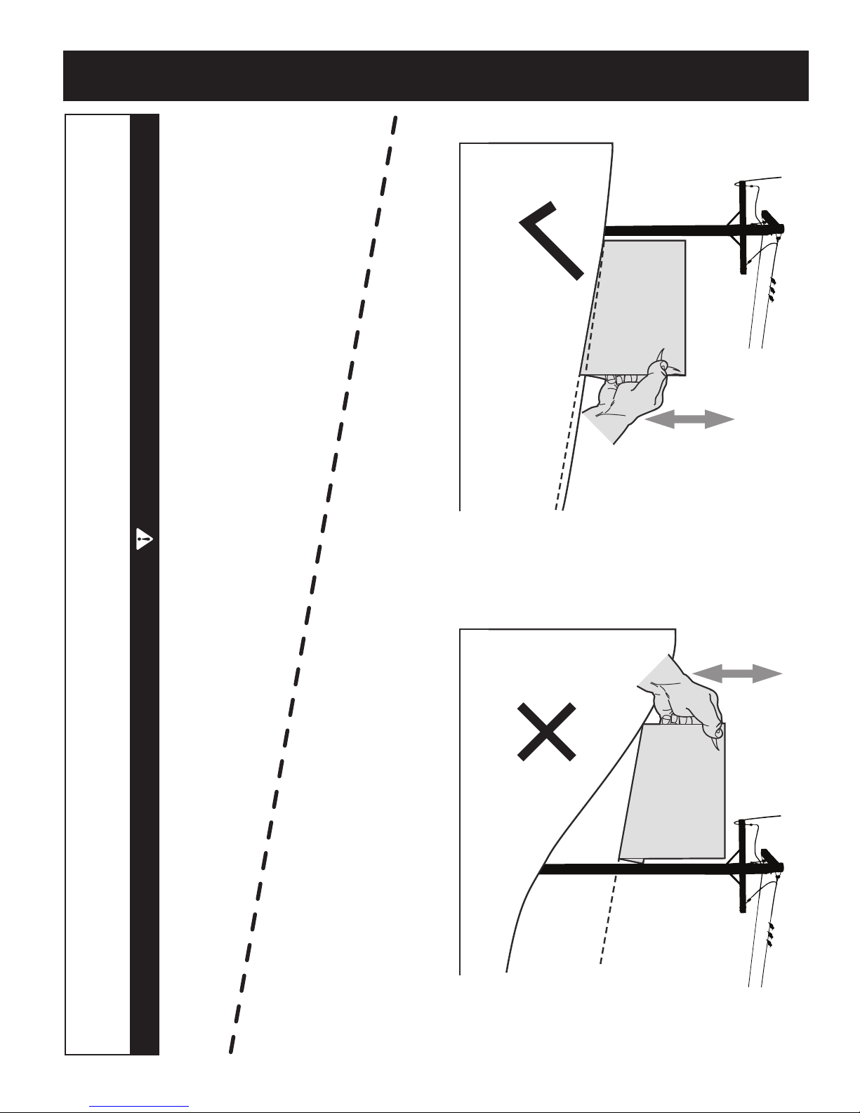
SLOPE GAUGE
Slopes are a major factor related to tip-over and roll-over accidents which can result in severe injury or death. Do not operate machine
on slopes in excess of 10 degrees. All slopes require extra caution. If you cannot back up the slope or if you feel uneasy on it, do not
mow it. Always mow up and down the face of slopes, never mow across the face of slopes.
To check the slope, proceed as follows:
1. Remove this page and fold along the dashed line.
2. Locate a vertical object on or behind the slope (e.g. a pole, building, fence, tree, etc.)
3. Align either side of the slope gauge with the object (See Figure 1 and Figure 2 ).
4. Adjust gauge up or down until the left corner touches the slope (See Figure 1 and Figure 2).
5. If there is a gap below the gauge, the slope is too steep for safe operation (See Figure 2 above).
(OK) (TOO STEEP)
IF A SLOPE IS TOO STEEP FOR SAFE OPERATION!
USE THIS SLOPE GAUGE TO DETERMINE
WARNING
10° dashed line
Figure 2Figure 1
10° Slope
Slope Gauge
10° Slope
5
Page 6
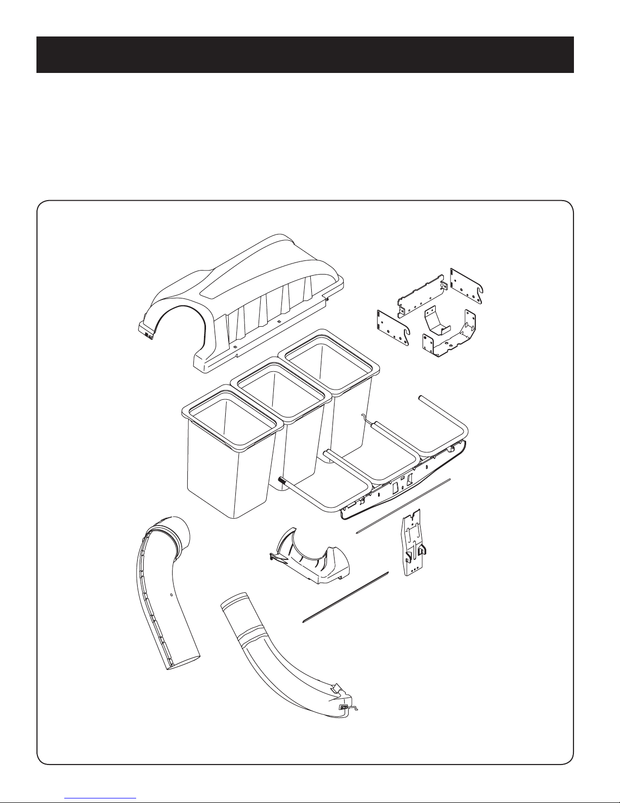
CONTENTS OF CARTON
Before beginning installation, remove all parts from the carton to make sure everything is present. Carton contents are listed and shown below. Two hardware packs are
included in this kit and are detailed on the following page.
• Grass Catcher Cover
• Hitch Bracket Kit (3 Pcs.)
• Bagger Support Bracket
• Hitch Support
• Three Grass Bag Assemblies
• Upper Chute Support
• Bag Support Assembly
• Upper Chute Tube
• Discharge Chute Elbow
• Hinge Cover Pin
• Foam Self-adhesive strip
• Upright Support
• Two Hardware Packs (Detailed & illustrated on next page)
6
Page 7
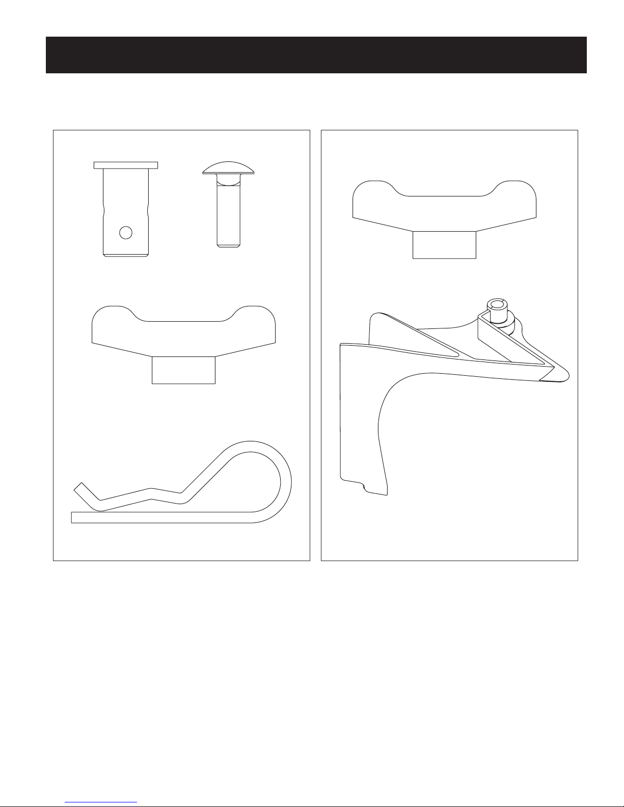
CONTENTS OF HARDWARE PACKS
689-00328A
This grass collector kit is shipped with two loose hardware packs enclosed. Please check your hardware packs against the illustrations below. The quantities for each item is
listed in parenthesis.
Hardware Pack
711-0309A
(1)
720-04122
Hardware Pack 689-00341
(6)
(1)
710-0276
720-04122
(1)
(6)
714-0117
(1)
731-10133
7
Page 8
Use this mounting
hole
ASSEMBLY AND INSTALLATION
NOTE: References to left, right, front and rear of the trac tor are from the operator’s
position, unless otherwise stated.
• Before assembly, place the tractor on a firm, level surface, disengage the
PTO, stop the tractor engine and set the parking brake.
• For convenience, pivot the seat forward and leave it in that position until the
grass collector is fully mounted and assembled.
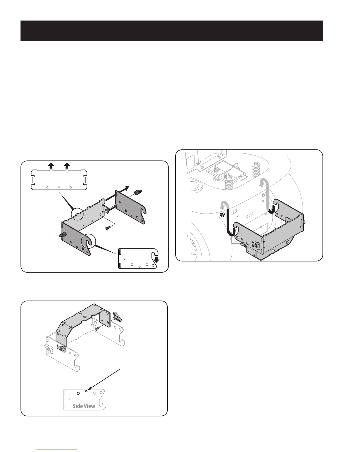
Assemble Mounting Brackets
To assemble the bagger mounting assembly, locate the mounting assembly pack
and follow these steps:
1. Attac h the two hitch side brackets to the univers al rear attachment bracket using
two carriage b olts (710-0276) and wing knobs (720-04122) from hardware pack
689 -0032 8A.
Note: The hooks on the side brackets should point downwards and the tabs
on the rear plate point upwards as shown in Figure 1.
NOTE: It may be easier during the mounting stage to leave this hardware only finger
tight to facilitate lining up the hitch hole for the clevis pin. You will be instructed to
tighten this hardware later in this manual.
NOTE: This universal mounting bracket assembly is designed to work with other
available attachments, such as a weight kit used in conjunction with the snow blade
or snow thrower attachment. Utilize the contact information on the back cover of
this manual, or refer to the Owner’s Manual that came with the trac tor, to find out
more about available attachments for your specific model.
Mount Assembly on Tractor
Install mounting assembly onto the tractor as follows:
1. Place the hooked ends of the mounting assembly over the shoulder bolts, as
in Figure 3, on the tractor and line up the hitch support bracket center hole
with the hole on the trac tor’s hitch.
Figure 1
2. Flip over assembly and mount the hitch support bracket to the mounting
assembly as shown in Figure 2.
Figure 2
Figure 3
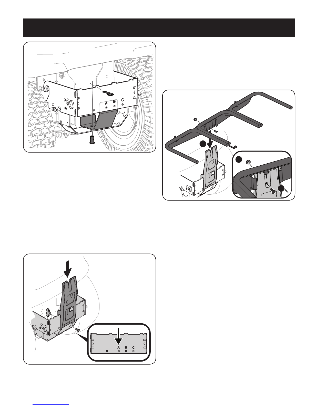
2. Install the bagger support bracket, included with the loose par ts, into the
mounting assembly as shown in Figure 4. Line the holes up as shown.
Note: The bagger suppport bracket is not intended for units with the diff lock
transmission.
3. Install the clevis pin (711-0309A) from hardware pack 689-00328A into the
tractor’s hitch, the bagger support bracket, and the mounting assembly and
secure with a hairpin clip (714-0117). See Figure 4.
Note: The clevis pin can be fed down through the hitch plate and secured
underneath with the hairpin clip, or it may be easier to feed the clevis pin up
through the hitch plate hole and secure with the hairpin clip on the topside.
The latter method may be preferred since it can be easier to insert the
hairpin clip. Either way will work, the decision should be based on operator
preference.
8
Page 9
ASSEMBLY AND INSTALLATION
1
2
2
Figure 4
Note: If you decided to leave the hitch support only finger tight during the
assembly process, tighten all of the hardware securely at this time.
4. Install the bagger upright mounting bracket onto the mounting assembly of
the tractor by hooking it over the hitch plate, aligning the center hole on the
upright bracket with the hole on the cross mount bracket which corresponds
with the deck size of your tractor. See Figure 5.
• Hole A recommended for 50” & 54” decks
5. Secure the upright mounting bracket to the mounting assembly using a
(710-0276) carriage bolt and a (720-04122) wing knob from hardware pack
689-00328A. Refer to Figure 5.
NOTE: Some kits may contain cross-mount brackets with numerical
identification over the holes instead of letters as shown. If this is the case,
use the hole corresponding to the deck size the bagger is being installed on.
6. Using a 1/2” wrench or socket, secure the hanger assembly to the upright
mounting assembly using another (710-0276) carriage bolt from hardware
pack 689-00328A and flange lock nut packed in with the upright mounting
bracket. See Figure 6.
Note: Upon completion of this bagging unit, there will be one(1) extra wing
knob from Hardware pack 689-00328A and two(2) carriage bolts and one(1)
flange lock nut, that was packed in with the upright mounting bracket.
Figure 6
Figure 5
9
Page 10
1
2
ASSEMBLY AND INSTALLATION
Cover mounts in
between these
two tabs
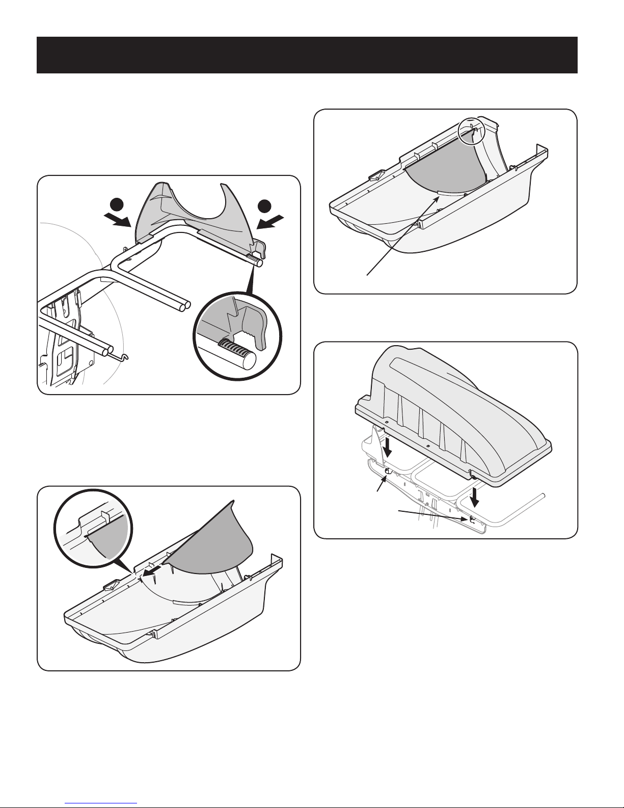
Assembling Remaining Bagger Components
Now that the mounting brackets are assembled and are in place on the tractor,
follow these steps to assemble the remaining bagger components.
1. Snap the plastic upper chute support in place by first clipping the side
portion onto the bagger support rail (1) with the edge of the snap feature
aligned with the red line, as shown in the inset of Figure 7.
4. Clip in the other side by flexing the screen and pushing it down into the
provided cutout hole. See Figure 9.
Make sure screen sits under the cover’s lip
Figure 9
5. Install the bagger cover onto the bag support assembly, as shown in Figure
10. The plastic cover goes inside of the two mounting tabs.
Figure 7
2. Snap the front side of the chute support to the rail (2), as shown in Figure 7.
3. If not previously installed by the factory, install the bagger screen into the
bagger cover by first inserting the end closest to the center into the cutout
mounting hole, as in Figure 8. Make sure to feed the screen under the lip, as
in Figure 9.
Figure 8
Figure 10
10
Page 11

1
2
1
2
ASSEMBLY AND INSTALLATION
6. Slide the hinge pin into the hole located on the mounting tab, as in Figure
11. Use the cut-out window (See inset in Figure 11) to line up the hinge pin
on the other side and push pin all the way in until it reaches the end-stop. At
this point the pin clips into place and is secured by a tab in the bagger cover.
See Figure 12.
Figure 11
7. Open Hood by pushing in on the rear, right-side tab with your right hand, as
shown in 1 of Figure 13, and lifting the cover with your left hand in the center
rear of the bagger cover, 2.
Figure 13
8. Install the bag assemblies onto the bag support brackets by inserting the
front edge in first, as shown in Figure 14, and setting the back edge down
until it fits into the assembly.
Figure 12
Figure 14
11
Page 12

2
4
1
3
Do Not Use This Hole!
Flange
ASSEMBLY AND INSTALLATION
Assembling the Discharge Chute
Before installing the discharge chute onto your tractor, a component must first be
assembled onto the upper chute tube. The following instructions are for assembling
the discharge chute:
NOTE: Check the upper chute for a cardboard insert installed for shipping purposes.
If the insert is present, remove it before continuing with Step 1.
1. Peel the backing off of the self-adhesive foam strip (721-04388) that has
been included with your grass collector. Apply it to the upper chute, flush
against the flange as shown in Figure 15.
Figure 16
4. Insert the end of the discharge chute elbow(3) into the hole provided in the
deck wheel mount as shown in the inset of Figure 16.
5. Pivot the discharge chute rearward until the hole in the discharge chute
elbow aligns with the pin on the deck. Move the discharge elbow down onto
that pin as shown in 4 of Figure 16.
6. Secure the discharge chute elbow to the cut ting deck using a (720-04122)
wing knob included in Hardware Pack 689-00341. Refer to Figure 17.
Figure 15
Installing the Discharge Chute
When installing the discharge chute, two different installation instructions exist.
For the 54” Fabricated deck units, the discharge chute elbow mounts directly onto
the cutting deck. For the 50” and 54” stamped decks, an adapter must first be
installed. Be sure to follow the instructions that pertain to the unit you are installing
this bagger on.
54” Fabricated Deck Units:
1. Raise the deck to its highest position.
2. Remove the deck pin rubber protective cap, 1 in Figure 16.
3. Raise the chute deflec tor (2 in Figure 16) on the deck and hold it while you
position the discharge chute over the chute opening.
Figure 17
12
Page 13

1
3
2
Do Not Use This Hole!
1
2
ASSEMBLY AND INSTALLATION
On 50” and 54” Stamped Decks:
1. Raise the deck to its highest position.
2. Remove the deck pin rubber protective cap, 1 in Figure 18.
3. Raise the chute deflec tor (2 in Figure 18) on the deck and hold it while you
install the (731-10133) chute adapter(3), included in hardware pack 68900341, onto the deck as shown in Figure 18.
6. Secure the discharge chute elbow to the cut ting deck using a (720-04122)
wing knob included in hardware pack 689-00341. Refer to Figure 20.
Figure 20
IMPORTANT: Be certain that the bottom of the discharge chute is located
inside of the lip of the deck opening, as shown in Figure 21.
Figure 18
4. Insert the end of the discharge chute elbow (1) into the hole provided in the
deck wheel mount as shown in the inset of Figure 19.
5. Pivot the discharge chute rearward until the hole in the discharge chute
elbow aligns with the pin on the deck adapter. Move the discharge elbow
down onto that pin as shown in 2 of Figure 19.
Figure 19
Figure 21
13
Page 14

ASSEMBLY AND INSTALLATION
7. With the bagger cover open, insert the upper chute tube into the discharge
chute then pivot the upper chute tube into position so that the chute rests in
the upper chute support. See Figure 22.
Note: Make sure to align the upper chute with the ridges on the upper chute
support.
Figure 22
14
Page 15

OPERATION
1
2
2
1
Bagger Operation
NOTE: When all of the grass bags are full, place the tractor on a firm, level
surface, disengage the PTO, turn the tractor engine off and set the parking
brake.
1. Pivot the seat forward and up.
2. Lift up grass bag cover by pushing in on the rear, right-side tab with your
right hand, as seen in 1 of Figure 23, and lifting the cover with your left
hand in the center rear of the bagger cover, 2. Do not remove the chute tube
assembly from the tractor.
Figure 24
4. Empty the grass clippings at a proper disposal sight, use the handle at the
bottom of each grass bag. Holding the bag firmly, empty the contents
5. Replace the grass bags in the reverse order and in the same orientation in
which they were removed, close lid, pivot down the seat, restart your tractor
and resume cutting your grass.
Figure 23
3. Remove the grass bags, as shown in Figure 24, by lifting each bag up (1) and
moving the bags away from the bag support assembly (2).
15
Page 16

TABLE OF CONTENTS
Sinstrucciones De Seguridad .............................................................................17
Contenido de la Caja .............................................................................................20
Montaje e Instalación............................................................................................22
Operación .................................................................................................................29
Números de servicio .................................................................... Volver Portada
CRAFTSMAN GARANTÍA LIMITADA
Por dos años desde la fecha de venta de este producto está garantizado contra defectos en materiales o mano de obra.
CON PRUEBA DE VENTA un producto defectuoso será reemplazado de forma gratuita.
Para detalles de la cobertura de la garantía para obtener la sustitución gratuita, visite la página web: www.craftsman.com/warranty
Esta garantía no cubre las bolsas de recogida de hierba paño, que son piezas fungibles que se desgasten por uso normal dentro del periodo de
garantía.
Esta garantía no se aplica a un producto que esté dañado o alterado a través del transporte, mal uso, abuso, corrosión, accidente, modificación
negligencia o mal manejo.
Esta garantía es nula si el producto se utiliza alguna vez mientras que proporciona servicios comerciales o si alquila a otra persona.
Esta garantía le otorga derechos legales específicos, y usted también puede tener otros derechos que varían de estado a estado.
Sears Brands Management Corporation, Hoffman Estates, IL 60179
© Sears Brands, LLC
16
Page 17

INSTRUCCIONES DE SEGURIDAD
ADVERTENCIA
La presencia de este símbolo indica que se trata de instrucciones
importantes de seguridad que se deben respetar para evitar poner
en peligro su seguridad personal y/o material y la de otras personas.
Lea y siga todas las instrucciones de este manual antes de poner
en funcionamiento esta máquina. Si no respeta estas instrucciones
podría provocar lesiones personales. Cuando vea este símbolo, ¡preste
atención a la advertencia!
ADVERTENCIA
PROPOSICIÓN 65 DE CALIFORNIA
El escape del motor de este producto, algunos de sus componentes y
algunos componentes del vehículo contienen o liberan sustancias químicas
que el estado de California considera que pueden producir cáncer, defectos
de nacimiento u otros problemas reproductivos. Los bornes de la batería y
los accesorios afines contienen plomo y compuestos de plomo, sustancias
químicas que según lo establecido por el Estado de California causan cáncer
y daños en el sistema reproductivo. Lávese las manos después de estar en
contacto con estos componentes.
Funcionamiento general
1. Lea, comprenda y respete todas las instrucciones que figuran
en el equipo y en los manuales antes de intentar armarlo y
hacerlo funcionar. Guarde este manual en un lugar seguro
para consultas futuras y periódicas, así como para solicitar
repuestos.
2. Para ayudar a evitar una lesión por contacto con las cuchillas
o con un objeto que sea arrojado, mantenga a las personas
que observan, a los ayudantes, niños y mascotas alejados a no
menos de 25 metros de la máquina mientras está funcionando.
Detenga la máquina si alguien entra en la zona.
3. Revise minuciosamente el área donde se va a usar el equipo.
Retire todas las piedras, palos, cables, huesos, juguetes y otros
objetos extraños que podrían ser recogidos y arrojados por la
acción de las cuchillas. Los objetos arrojados por la máquina
pueden causar lesiones graves.
4. Para protegerse los ojos, utilice siempre gafas o lentes de
seguridad mientras opera la máquina o mientras la ajusta
o repara. Los objetos arrojados que rebotan pueden causar
lesiones oculares graves.
5. Nunca opere la cortadora de césped sin tener bien colocada
la cubierta de descarga o el colector de césped. Si falta o
está dañada la cubierta de descarga o un componente del
accesorio embolsador puede resultar en lesiones por contacto
con la cuchilla o con objetos arrojados.
6. No ponga las manos ni los pies cerca de las piezas rotatorias ni
debajo de la plataforma de corte. El contacto con las cuchillas
puede resultar en la amputación de una mano o pie.
7. Apague el motor de la cortadora de césped y espere que
las cuchillas se detengan totalmente antes de desbloquear
la abertura de descarga de la cortadora o las piezas de la
embolsadora.
PELIGRO
Esta máquina fue construida para ser operada de acuerdo con las reglas
de seguridad contenidas en este manual. Al igual que con cualquier
tipo de equipo motorizado, un descuido o error por parte del operador
puede producir lesiones graves. Esta máquina es capaz de amputar
manos y pies y de arrojar objetos con gran fuerza. De no respetar las
instrucciones de seguridad siguientes se pueden producir lesiones
graves o la muerte.
ADVERTENCIA
Su responsabilidad—Restrinja el uso de esta máquina motorizada a
las personas que lean, comprendan y respeten las advertencias e instrucciones que aparecen en este manual y en la máquina.
¡GUARDE ESTAS INSTRUCCIONES!
8. Reduzca la velocidad antes de girar. Opere la máquina de
forma pareja. Evite el funcionamiento errático y la velocidad
excesiva. Tenga en cuenta que el accesorio colector de césped
puede afectar las características de manejo de su cortadora.
Funcionamiento en pendientes
Las pendientes son un factor importante en los accidentes
ocasionados por pérdida de control y vuelcos que pueden causar
lesiones graves e incluso la muerte. Los accesorios tambíen pueden
afectar la estabilidad de la máquina. La operación en pendiente
requiere mayor precaución.
Para seguridad, use el medidor de pendientes que se incluye como
parte de este manual para estimar el ángulo de la pendiente antes
de hacer funcionar la máquina en una zona inclinada. Si la pendiente
es mayor a 10 grados en el medidor, no opere la cortadora con el
accesorio embolsador en ese sector, pues podría causar lesiones
graves.
Haga lo siguiente:
1. Corte hacia arriba y abajo de las pendientes, no en forma
transversal. Tenga sumo cuidado al cambiar de dirección en
una pendiente.
2. Esté atento a los hoyos, surcos, baches, rocas, u otros objetos
ocultos. El terreno desnivelado puede voltear la máquina. El
pasto alto puede ocultar obstáculos.
3. Conduzca a baja velocidad. Elija una velocidad lo
suficientemente baja como para no tener que detenerse
o cambiar de marcha mientras está en la pendiente. Los
neumáticos pueden perder tracción en las pendientes aún
cuando los frenos funcionen correctamente. Mantenga
la máquina siempre en velocidad cuando desciende una
pendiente, para poder frenar con el motor.
22
Page 18

INSTRUCCIONES DE SEGURIDAD
4. Siga las recomendaciones del fabricante sobre pesos y
contrapesos de las ruedas, para mejorar la estabilidad.
5. Haga que todos los movimientos en las pendientes sean
lentos y graduales. No cambie repentinamente la velocidad
ni la dirección. Un frenado o cambio de velocidad repentinos
pueden causar que el frente de la máquina se levante y dé una
voltereta hacia atrás, lo que podría causar lesiones graves.
6. Evite arrancar o detenerse en una pendiente. Si los neumáticos
pierden tracción, desenganche las cuchillas y descienda
lentamente la pendiente.
No haga lo siguiente:
1. No gire en una pendiente a menos que sea imprescindible. De
ser posible, gire lenta y gradualmente cuesta abajo.
2. No corte el césped cerca de barrancos, zanjas o terraplenes. La
cortadora de césped podría volcarse repentinamente si una de
las ruedas estuviera sobre el borde de un acantilado o zanja, o
si un borde se desmoronara.
3. No intente estabilizar la máquina poniendo el pie en el suelo.
4. No utilice un colector de césped en pendientes empinadas.
5. No corte el césped húmedo. Una reducción en tracción puede
causar derrapes.
Servicio general
1. Antes de limpiar, reparar o inspeccionar la máquina,
compruebe que las cuchillas y todas las piezas móviles se
hayan detenido. Desconecte el cable de la bujía y póngalo
haciendo masa contra el motor para evitar que arranque
accidentalmente.
2. Mantenga todas las tuercas, pernos y tornillos bien ajustados
para asegurarse de que el equipo está en condiciones seguras
de operación.
3. Nunca intente violar el sistema de bloqueo de seguridad u
otros mecanismos de seguridad de la cortadora. Controle
periódicamente que funcionan correctamente.
4. No intente nunca hacer ajustes o reparaciones a la cortadora
mientras el motor está en marcha.
5. Los componentes del colector de césped y la cubierta de
descarga están sujetos a desgaste y daños que podrían dejar
expuestas piezas que se mueven o permitir que se arrojen
objetos. Para proteger su seguridad, verifique frecuentemente
todos los componentes y reemplácelos inmediatamente
únicamente con piezas de los fabricantes del equipo original
(O.E.M.) indicados en este manual. El uso de piezas que no
cumplen con las especificaciones del equipo original puede
resultar en rendimiento inadecuado y puede poner en peligro
la seguridad.
6. Mantenga o reemplace las etiquetas de seguridad y de
instrucciones según sea necesario.
Símbolos de seguridad
En esta página se presentan y describen los símbolos de seguridad que pueden aparecer en este producto. Lea, entienda y cumpla todas las
instrucciones incluidas en la máquina antes de intentar armarla y utilizarla.
Símbolo Descripción
LEA LOS MANUALES DEL OPERADOR
Lea, entienda y cumpla todas las instrucciones incluidas en los manuales antes de intentar armar la
unidad y utilizarla.
DETENCIÓN
Apague el motor antes de abrir la cubierta de la embolsadora.
¡ADVERTENCIA! Su responsabilidad—Limite el uso de esta máquina motorizada a las personas que lean,
comprendan y cumplan las advertencias e instrucciones que aparecen en este manual y en la máquina.
¡GUARDE ESTAS INSTRUCCIONES!
23
Page 19

PENDIENTE DE CALIBRE
ADVERTENCIA
Las pendientes son un factor importante relacionado con un vuelco y renovación de los accidentes que pueden provocar lesiones
graves o la muerte. No utilice la máquina en pendientes de más de 10 grados. Todos pendientes requiere mayor precaución. Si no
puede retroceder en la pendiente o si se siente inseguro en ella, no la recorte. Siempre corte el césped arriba y abajo las pendientes,
nunca en toda la superficie de la cuesta.
24
Page 20

CONTENIDO DE LA CAJA
Antes de comenzar la instalación, quite todas las piezas de la caja para asegurarse de que todo está presente. Contenido de la caja se enumeran y se muestran a
continuación. Dos paquetes de hardware se incluyen en este kit y se detallan en la página siguiente.
• Hierba cubier ta Catcher
• Juego de sopor te de enganche (3 Pcs.)
• Bagger Soporte Soporte
• Apoyo Hitch
• Tres conjuntos de la bolsa de recolección
• Soporte superior Chute
• Conjunto de sopor te Bolsa
• Alta Chute Tubo
• Conducto de descarga Codo
• Bisagra Cubierta Pin
• Espuma autoadhesiva tira
• Soporte ver tical
• Dos paquetes de Hardware (detallada y se ilustra en la página siguiente)
20
Page 21

CONTENIDO DEL PAQUETE DE HERRAJES
689-00328A
Este kit colector de hierba se envía con dos paquetes de hardware sueltos cerrados. Se recomienda consultar los paquetes de hardware contra las siguientes ilustraciones.
Las cantidades de cada elemento aparece en paréntesis.
Hardware Pack
711-0309A
(1)
720-04122
Hardware Pack 689-00341
(6)
(1)
710-0276
720-04122
(1)
(6)
714-0117
(1)
731-10133
21
Page 22

Utilice este orificio
de montaje
MONTAJE E INSTALACIÓN
NOTA : Las referencias a izquierda, derecha, parte delantera y trasera del tractor son
desde la posición del operador, salvo indicación en contrario.
• Antes de armar, coloque el tractor sobre una superf icie firme y nivelada,
desenganche la toma de fuerza (PTO), detenga el motor del tractor y coloque
el freno de mano.
• Para mayor comodidad, gire el asiento hacia adelante y déjelo en esa
posición hasta que el colector de pasto esté totalmente armado y montado.
Armado de las ménsulas de montaje
Para armar la unidad de montaje de la embolsadora, localice el paquete de la
unidad de montaje y siga estos pasos:
1. Fije los dos soportes laterales del enganche en el soporte de f ijación posterior
universal, utilizando dos tornillos de carruaje (710-0276) y las perillas de
mariposa (720-04122) del paquete de tornillería 689-00328.
Nota: Los ganchos de los soportes laterales deben apuntar hacia abajo y
las fichas en el punto de la placa trasera hacia arriba como se muestra en la
Figure 25.
Figure 26
Monte la unidad en el tractor
Instale la unidad de montaje sobre el tractor de esta manera:
1. Coloque los extremos con gancho de la unidad de montaje sobre los pernos
con reborde, como en la Figure 27, en el tractor y alinee el orificio central de
la ménsula de soporte de enganche con el orificio del enganche del tractor.
Figure 25
2. Flip over assembly and mount the hitch support bracket to the mounting
assembly as shown in Figure 26.
NOTA : Al acoplar el soporte de enganche, conviene no ajustar totalmente la
ménsula todavía. Esto facilitará el proceso de montaje más adelante, cuando
se deberá ajustar a fondo la ménsula del soporte de enganche.
NOTA : Esta unidad de la ménsula de montaje universal está diseñada
para funcionar con otros accesorios, como el juego de contrapesos que
se usa junto con la cuchilla para nieve o el accesorio quitanieve. Utilice la
información de contacto que aparece en la contratapa, o comuníquese con
la tienda donde adquirió el equipo, para obtener más información sobre los
accesorios disponibles para su tractor en particular.
Figure 27
2. Instale el soporte del contenedor, incluido con las piezas sueltas, en el conjunto
de montaje como se muestra en. Línea de los agujeros como se muestra.
Nota: El soporte de soporte de la bolsa no está diseñado para unidades con
la transmisión de bloqueo de dif.
3. Instale el pasador de horquilla (711-0309A) del paquete de tornillería 68900328A en el enganche del tractor, el soporte del contenedor, y el conjunto de
montaje y asegure con un pasador de horquilla (714-0117). See Figure 28.
Nota: El pasador de horquilla se puede pasar hacia abajo por la placa de
enganche y asegurarlo por bajo con el broche de horquilla; o puede resultar
más fácil pasarlo hacia arriba y asegurarlo en la parte superior. Este último
método suele ser el preferido ya que puede ser más fácil insertar el broche de
horquilla. Cualquiera de los dos es correcto, la decisión depende de la
22
Page 23

1
2
2
1
2
MONTAJE E INSTALACIÓN
preferencia del operador.
Figure 28
Nota: Si decidió dejar el soporte de enganche ajustado sólo a mano durante
el armado, en este momento debe ajustar bien todos los elementos de
ferretería.
4. Instale el soporte de montaje en posición vertical embolsadora en el
conjunto de montaje del tractor enganchándolo sobre la placa de enganche,
alineando el orificio central en el sopor te en posición vertical con el agujero
en la cruz soporte de montaje en la que se corresponde con el tamaño de la
cubierta de su tractor. See Figure 29.
• Agujero A recomienda para 50 “y 54” cubiertas
5. Fije el soporte de montaje en posición vertical para el conjunto de montaje
utilizando un (710-0276) perno y una perilla (720-04122) ala del paquete de
tornillería 689-00328A. Consulte Figure 29.
NOTA : Algunos equipos pueden contener soportes de montaje en cruz
con identificación numérica sobre los agujeros en lugar de letras, como se
muestra. Si este es el caso, utilice el agujero correspondiente al tamaño de la
cubierta de la embolsadora está siendo instalado.
Figure 29
6. Usando una “llave de media o socket, asegurar el conjunto de suspensión a la
posición vertical de montaje del conjunto utilizando otro perno (710-0276)
el transporte del paquete de tornillería 689-00328A y la brida de la tuerca de
seguridad empaquetada con el soporte de montaje vertical. See Figure 30.
Nota: Al finalizar esta unidad de ensacado, habrá un (1) Mando ala extra del
paquete Hardware 689-00328A y dos (2) pernos de carro y un (1) tuerca de
seguridad con brida, que estaba lleno con el soporte de montaje vertical .
Figure 30
Armado del resto de los componentes del recolector
Una vez que las ménsulas de montaje están armadas y colocadas en el tractor, siga
estos pasos para armar el resto de los componentes de la embolsadora.
1. Calce a presión el sopor te del canal superior colocando primero el lateral
sobre el riel de soporte del cubo con el borde que calza a presión alineado
con la línea roja (1), como se ve en el recuadro de la Figure 31.
Figure 31
2. Calce a presión la parte delantera del soporte del canal superior en el sopor te
23
del cubo, como se ve en 2 de la Figure 31.
Page 24

Cover mounts in
between these
two tabs
MONTAJE E INSTALACIÓN
3. Si no se instala previamente por la fábrica, instale la pantalla del colector
de césped en la cubierta de la embolsadora, insertando primero el extremo
más cercano al lado que tiene el recorte en el orif icio de montaje, como en la
Figure 32. Asegúrese de pasar la pantalla por debajo del reborde, como en la
Figure 33.
Figure 32
4. Calce el otro lado flexionando la pantalla y empujándola dentro del recorte
provisto. Vea la Figure 33.
Figure 34
6. Deslice el pasador de horquilla en el orificio ubicado en la lengüeta de
montaje, como se ve en la Figure 35. Use la ventana recortada (Vea el
recuadro de la Figure 35) para alinear el pasador de horquilla del otro
lado y empújelo hasta que llegue al tope. En este punto el pasador calza
en su posición y queda asegurado por una lengüeta de la cubierta de la
embolsadora. Vea la Figure 36.
Asegúrese que la pantalla descansa bajo el reborde de la cubierta
Figure 33
5. Instale la cubierta del colector de césped en la unidad de soporte del cubo,
como se ve en la Figure 34. La cubierta del colector de césped va dentro de
las dos lengüetas de montaje sobre la unidad de sopor te de los cubos.
Figure 35
24
Page 25

1
2
1
2
AMONTAJE E INSTALACIÓN
Figure 36
Abra la cubierta del colector empujando hacia adentro en la lengüeta posterior
derecha con la mano derecha, como se ve en 1 de la Figure 37, y levantando con la
mano izquierda en el centro de la par te posterior, 2.
7. Instale los cubos en su unidad de sopor te insertando primero el borde
delantero (1), como se ve en la Figure 38, y bajando el borde posterior hasta
que calce en la unidad.
Figure 38
Figure 37
25
Page 26

2
4
1
3
No utilice este agujero!
brida
MONTAJE E INSTALACIÓN
Montaje y configuración del Canal de Descarga
Antes de instalar el conducto de descarga en su tractor, un primer componente debe
ser montado en el tubo superior de la tolva. Las siguientes instrucciones para el
montaje y la configuración del canal de descarga:
NOTA : Verifique el canal superior de un inserto de cartón instalado para propósitos
de envío. Si el inserto está presente, quite antes de continuar con el Paso 1.
1. Pelar el respaldo fuera de la franja de espuma auto-adhesivo (721-04388)
que ha sido incluida con el colector de césped. Aplique a la tolva superior, a
ras con la brida como se muestra en la Figure 39.
Figure 39
Figure 40
4. Inserte el extremo del codo canal de descarga (3) en el orificio
correspondiente en la rueda de la cubierta de montaje como se muestra en la
inserción de la Figure 40.
5. Gire la tolva de descarga hacia atrás hasta que el agujero en el codo canal de
descarga se alinea con el pasador en la cubierta. Mueva el codo de descarga
hacia abajo en ese pin como se muestra en la Figure 40.
6. Asegure el codo canal de descarga de la plataforma de corte usando una
perilla (720-04122) ala incluida en Paquete Hardware 689-00341. Consulte
la Figure 41.
Instalación del conducto de descarga
Al instalar el canal de descarga, existen dos instrucciones de instalación diferentes.
Para las unidades de cubierta Fabricados de 54 “, el canal de codo de descarga
se monta directamente sobre la plataforma de corte. Para el 50 “y 54” cubiertas
estampadas, un adaptador se debe instalar primero. Asegúrese de seguir las
instrucciones que se refieren a la unidad que está instalando esta embolsadora en.
54 “unidades de cubierta fabricados:
1. Levante la plataforma a su posición más alta.
2. Retire la tapa protectora de goma pin deck, 1 en la Figure 40.
3. Levante el deflector del canal (2 en la Figure 40) en la cubierta y sostenerlo
mientras se coloca el tubo de descarga en la abertura del canal.
Figure 41
26
Page 27

1
3
2
No utilice este agujero!
1
2
MONTAJE E INSTALACIÓN
El 50 “y 54” Enteros Decks
1. Levante la plataforma a su posición más alta.
2. Retire la tapa protectora de goma pin deck, 1 en la Figure 42.
3. Levante el deflec tor del canal (2 en la Figure 42) en la cubierta y mantenerla
mientras se instala el adaptador (731-10133) tolva (3), incluido en el paquete de
hardware de 689- 00341, sobre la cubierta como se muestra en la Figure 42.
Figure 42
4. Inserte el extremo del codo canal de descarga (1) en el orificio
correspondiente en la rueda cubierta montaje según se indica en el recuadro
de Figure 43.
6. Asegure el codo canal de descarga de la plataforma de corte usando una
perilla (720 a 04.122) ala incluido en paquete de hardware 689-00341.
Consulte la Figure 44.
Figure 44
IMPORTANTE: Asegúrese de que la parte inferior de la tolva de descarga se
encuentra en el interior del labio de la abertura de la cubierta, como se muestra en
Figure 45.
Figure 43
5. Pivotar el canal de descarga hacia atrás hasta que el agujero en el codo
de conducto de descarga se alinea con el pasador en el adaptador de la
plataforma. Mueva el codo de descarga hacia abajo en ese pin como se
muestra en 2 de Figure 43.
Figure 45
27
Page 28

MONTAJE E INSTALACIÓN
7. With the bagger cover open, insert the upper chute tube into the discharge
chute then pivot the upper chute tube into position so that the chute rests in
the upper chute suppor t. See Figure 46.
Note: Make sure to align the upper chute with the ridges on the upper chute
support.
Figure 46
28
Page 29

Operación
1
2
2
1
Bagger Operación
NOTA : Cuando ambas bolsas están llenas de hierba, colocar el tractor en una
superficie firme y nivelada, desenganche la PTO (enganche de cuchilla), gire
el motor del tractor y ponga el freno de estacionamiento.
1. Voltear el asiento hacia adelante.
2. Abra la cubierta de hierba receptor empujando en la, pestaña del lado
derecho trasero con la mano derecha, como se muestra en (1) de la Figure 47,
y levantando con su mano izquierda en la parte central trasera, (2).
Figure 47
3. Sacar las bolsas de hierba levantándolos (1 en la Figure 48) y lejos del
conjunto de soporte de la bolsa (2).
Figure 48
4. Vacíe los recortes de la hierba en un vertedero adecuado. Sujete el asa en la
parte inferior de la bolsa con una mano y con la otra mano sujetar la bolsa, y
vaciar el contenido.
5. Vuelva a colocar las bolsas de hierba, cierre la tapa, voltee hacia abajo
asiento, reinicie el tractor y siga cortando el césped.
6. Vuelva a apretar todas las perillas de mariposa periódicamente durante toda
la temporada.
29
Page 30

Notes Page
This page intentionally left blank. Use this page to make any notes regarding your bagger.
19
Page 31

Notes Page
This page intentionally left blank. Use this page to make any notes regarding your bagger.
20
Page 32

Product questions or problems?
1-888-331-4569
Customer Care Hot Line
Get answers to questions, troubleshoot problems,
order parts, or schedule repair service.
Para respuestas a preguntas o problemas, y ordenar
piezas o pedir servicio para la reparación de su equipo.
To help us help you, register your product at www.craftsman.com/registration
Para poderte ayudar mejor, registra tu producto en www.craftsman.com/registration
Join the Craftsman Club today!
Receive exclusive member benefits including special pricing and offers,
project sharing, expert advice, and SHOP YOUR WAY REWARDS!
Como miembro exclusivo, recibe diversos beneficios como ofertas, precios especiales, proyectos
nuevos, consejos de expertos y nuestro programa de puntos SHOP YOUR WAY REWARDS!
® Registered Trademark / TM Trademark of KCD IP, LLC in the United States, or Sears Brands, LLC in other countries
® Marca Registrada /
TM
Marca de Fábrica de KCD IP, LLC en Estados Unidos, o Sears Brands, LLC in otros países
 Loading...