

Page 1

perator's
I:RnFrSMRN°
30 in. Two Bin Rear Bagger
for the Craftsman Rear Engine Rider 1000
Model No. 247.240690
• Espanol, P. 14
Before using this equipment,
read this manual and follow
all safety rules and operating
instructions.
\ \
/
For answers to your questions about
this product, call:
1-800-659-5917
CraftsmanTractorHelpLine
7 am = 7 pm CT, Mort. =Sun.
Sears Brands Management Corporation, Hoffman Estates, IL 60179, U.S.A.
Visit our website: www.craftsman.com
FormNo.769-08596
(December17,2012)
Page 2

Craftsman One Year Full Warranty
FORONEYEARfromthedateofpurchase,this productiswarrantedagainstanydefectsin materialorworkmanship.A defectiveproductwillbe
replacedfreeofcharge.
Forwarrantycoveragedetailsto obtainfreereplacement,visitthewebsite:www.craftsman.com
Thiswarrantydoesnotcovergrassbagassemblies,whichareexpendablepartsthatcanwearoutfromnormalusewithinthewarrantyperiod.
Thiswarrantyisvoidif thisproductiseverusedwhileprovidingcommercialservicesorif rentedtoanotherperson.
Thiswarrantygivesyouspecificlegalrights,andyou mayalsohaveotherrightswhichvaryfromstateto state.
Sears Brands Management Corporation, Idoffman Estates, IL 60179
© SearsBrands,LLC 2
Page 3
Thissymbolpointsoutimportantsafetyinstructionswhich,if not
followed,couldendangerthe personalsafetyand/orpropertyof
yourselfandothers.Readandfollow all instructionsinthismanual
beforeattempting tooperatethis machine.Failuretocomplywith these
instructionsmayresultinpersonalinjury.Whenyouseethissymbol,HEED
ITSWARNING!
Thismachinewasbuilt tobeoperatedaccordingtothesafeoperation
practicesinthis manual.Aswith anytype of powerequipment,
carelessnessorerroron the partoftheoperatorcanresultinseriousinjury.
Thismachineiscapableof amputating fingers, hands,toesandfeet and
throwingdebris.Failuretoobservethefollowingsafety instructionscould
resultinseriousinjuryordeath.
CALiFORNiA PROPOSITION 65
EngineExhaust,someof itsconstituents,andcertainvehiclecomponents
containoremit chemicalsknownto Stateof Californiatocausecancerand
birth defectsorother reproductiveharm.
Batteryposts,terminals,and relatedaccessoriescontain leadand lead
compounds,chemicalsknownto the StateofCaliforniatocausecancerand
reproductiveharm.Washhandsafter handling.
GENERAL OPERATION
Read,understand,andfollowall instructionsonyourequipmentandintheir
manualsbeforeattemptingtoassembleandoperate.Keepthismanualin
asafeplaceforfutureandregularreferenceandfororderingreplacement
parts.
Tohelpavoidbladecontactorathrownobjectinjury,keepbystanders,
helpers,childrenandpetsatleast75feetfromthemowerwhileitisin
operation.Stopmachineifanyoneentersthearea.
Thoroughlyinspecttheareawheretheequipmentistobeused.Remove
allstones,sticks,wire,bones,toys,andotherforeignobjectswhichcould
bepickedupandthrownbytheblade(s).Thrownobjectscancauseserious
personalinjury.
Alwayswearsafetyglassesorsafetygogglesduringoperationandwhile
performinganadjustmentor repairtoprotectyoureyes.Thrownobjects
whichricochetcancauseseriousinjurytotheeyes.
Donotoperatethemowerwithoutthedischargecoverorentiregrass
catcherinitsproperplace.A missingordamageddischargecoverorgrass
bagattachmentcomponentmayresultinthrownobjectsorbladecontact
injuries.
Donotputhandsorfeetnearrotatingpartsorunderthecuttingdeck.
Contactwith theblade(s)canamputatehandsandfeet.
Shutoffmower'sengineandwaitforbladesto cometoacompletestop
beforeuncloggingmower'sdischargeopeningorbaggerparts.
Slowdownbeforeturning.Operatethemachinesmoothly.Avoiderratic
operationandexcessivespeed.Beawarethatagrasscatcherattachmentcan
affectthehandlingcharacteristicsofyourmower.
Disengageblade(s),setparkingbrake,stopengineandwaituntil the
blade(s)cometoa completestopbeforeopeningbaggerattachment'stop
cover,removinggrasscatcher,emptyinggrass,uncloggingchute,removing
anygrassordebris,or makinganyadjustments.
Your Responsibility--Restrict theuseofthis powermachineto
personswho read,understandandfollow thewarningsand instructionsin
thismanualandonthemachine.
SAVETHESEINSTRUCTIONS!
Neverleavea runningmachineunattended.Alwaysturnoffblade(s),place
transmissioninneutral,setparkingbrake,stopengineandremovekey
beforedismounting.
Yourmachineisdesignedtocut normalresidentialgrassofaheightnomore
than10".Donotattemptto mowthroughunusuallytall,drygrass(e.g.,
pasture)orpilesofdryleaves.Drygrassorleavesmaycontacttheengine
exhaustand/orbuilduponthemowerdeckpresentingapotentialfire
hazard.
Ifsituationsoccurwhicharenotcoveredinthismanual,usecareandgood
judgment.
SLOPE OPERATION
Slopesareamajorfactorrelatedtolossofcontrolandtip-overaccidentswhichcan
resultinsevereinjuryordeath.Allslopesrequireextracaution.Ifyoucannotback
uptheslopeorifyoufeeluneasyonit,donotmowit.
Foryoursafety,usetheSlopeGuideincludedaspartofthismanualtomeasure
slopesbeforeoperatingthismachineon aslopedorhillyarea.Iftheslopeisgreater
than10degreesasshownontheSlopeGuide,donotoperatethismachineonthat
areaorseriousinjurycouldresult.
Do;
Mowupanddownslopes,notacross.Exerciseextremecautionwhen
changingdirectiononslopes.
Watchforholes,ruts,bumps,rocks,orotherhiddenobjects.Uneventerrain
couldoverturnthemachine.Tallgrasscanhideobstacles.
Useslowspeed.Choosealowenoughspeedsettingsothatyouwill nothave
tostoporshiftwhileontheslope.Tiresmaylosetractiononslopeseven
thoughthebrakesarefunctioningproperly.Alwayskeepmachineingear
whengoingdownslopestotakeadvantageofenginebrakingaction.
Followthemanufacturer'srecommendationsforwheelweightsor
counterweightsto improvestability.
Page 4
Keepallmovementontheslopesslowandgradual.Donotmakesudden
changesinspeedordirection.Rapidengagementorbrakingcouldcause
thefrontofthemachinetoliftandrapidlyflipoverbackwardswhichcould
causeseriousinjury.
Avoidstartingorstoppingonaslope.Iftireslosetraction,disengagethe
blade(s)andproceedslowlystraightdowntheslope.
Do Not:
Donotturn onslopesunlessnecessary;then,turn slowlyandgradually
downhill,ifpossible.
Donotmowneardrop-offs,ditchesorembankments.Themowercould
suddenlyturn overifawheelisovertheedgeofacliff,ditch,orif anedge
cavesin.
Donottry tostabilizethemachinebyputtingyourfootontheground.
Donotuseagrasscatcheronsteepslopes.
Donotmowonwetgrass.Reducedtractioncouldcausesliding.
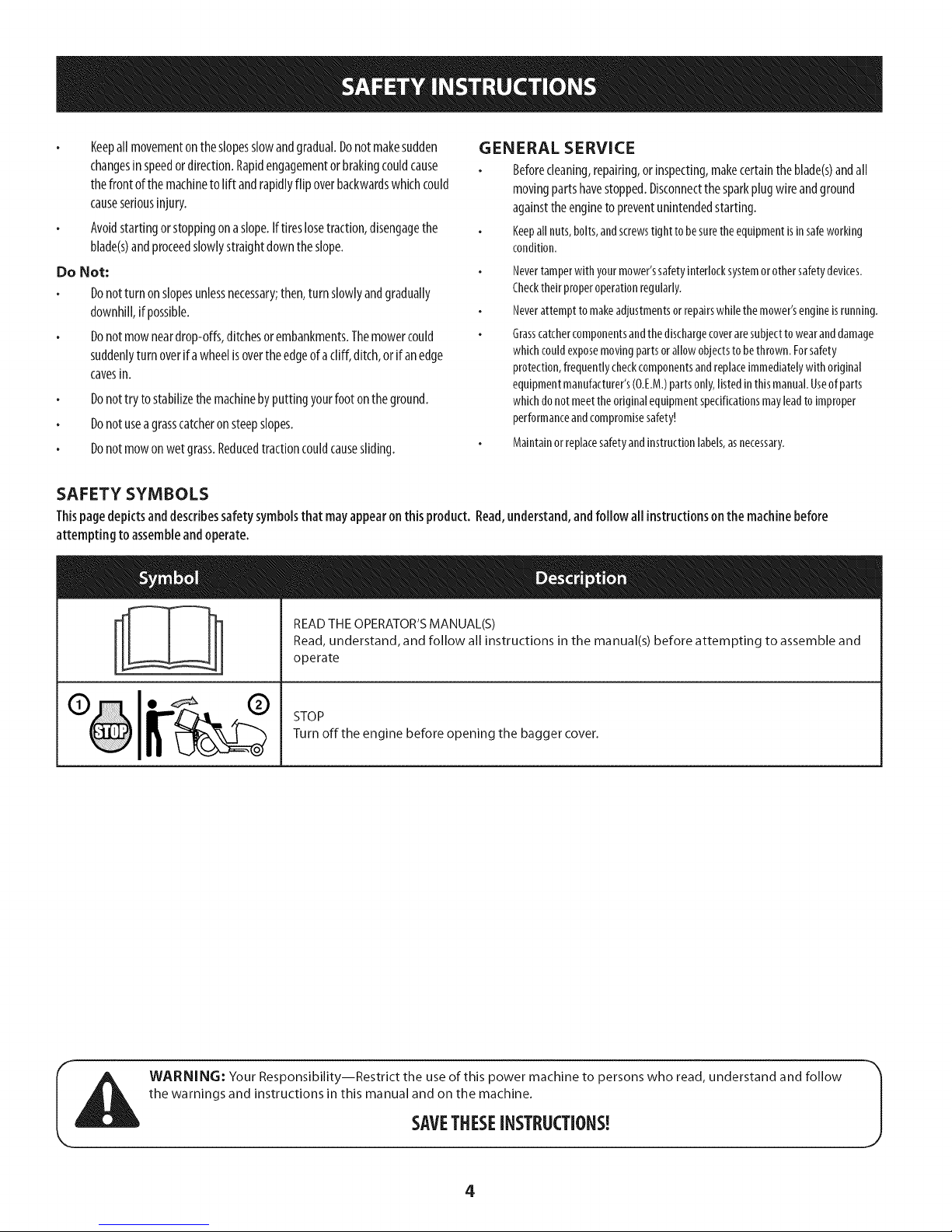
SAFETY SYMBOLS
Thispagedepictsanddescribessafetysymbolsthat mayappearonthis product. Read,understand,andfollow all instructionsonthe machinebefore
attempting toassembleandoperate.
GENERAL SERVICE
Beforecleaning,repairing,orinspecting,makecertaintheblade(s)andall
movingpartshavestopped.Disconnectthesparkplugwireandground
againsttheenginetopreventunintendedstarting.
Keepallnuts,bolts,andscrewstighttobesuretheequipmentisinsafeworking
condition.
Nevertamperwith your mower'ssafetyinterlocksystemorothersafetydevices.
Checktheirproperoperationregularly.
Neverattempt tomakeadjustmentsor repairswhilethe mower'sengineisrunning.
Grasscatchercomponentsandthe dischargecoveraresubjecttowearanddamage
whichcouldexposemovingpartsorallow objectsto bethrown.Forsafety
protection,frequentlycheckcomponentsandreplaceimmediatelywith original
equipmentmanufacturer's(O.E.M.)partsonly,listedinthis manual.Useof parts
whichdonot meettheoriginalequipmentspecificationsmayleadto improper
performanceandcompromisesafety!
Maintainorreplacesafetyandinstructionlabels,asnecessary.
%
READ THE OPERATOR'S MANUAL(S)
Read, understand, and follow all instructions in the manual(s) before attempting to assemble and
operate
STOP
Turn off the engine before opening the bagger cover.
WARNING: Your Responsibility--Restrict the useof this power machine to persons who read, understand and follow
the warnings and instructions in this manual and on the machine.
SAVETHESEINSTRUCTIONS!
4
Page 5
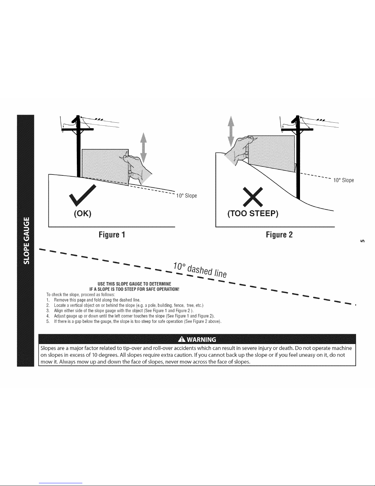
(OK)
10° Slope
(TOO STEEP)
10° Slope
Figure1
USETHiSSLOPEGAUGETODETERMINE
iFASLOPEiSTOOSTEEPFORSAFEOPERATION!
Tochecktheslope,proceedasfollows:
1. Removethispageandfold alongthe dashedline.
2. Locateaverticalobjectonor behindthe slope(e.g.apole,building,fence, tree,etc.)
3. Aligneithersideof theslopegaugewiththe object(SeeFigure1andFigure2).
4. Adjustgaugeup or down until theleft cornertouchestheslope(SeeFigure1andFigure2).
5.
10odashedline
If there isa gapbelowthegauge,theslopeis too steepfor safeoperation(SeeFigure2 above).
Figure2
Slopes are a major factor related to tip-over and roll-over accidents which can result in severe injury or death. Do not operate machine
on slopes in excess of 10 degrees. All slopes require extra caution. If you cannot back up the slope or if you feel uneasy on it, do not
mow it. Always mow up and down the face of slopes, never mow across the face of slopes.
Page 6
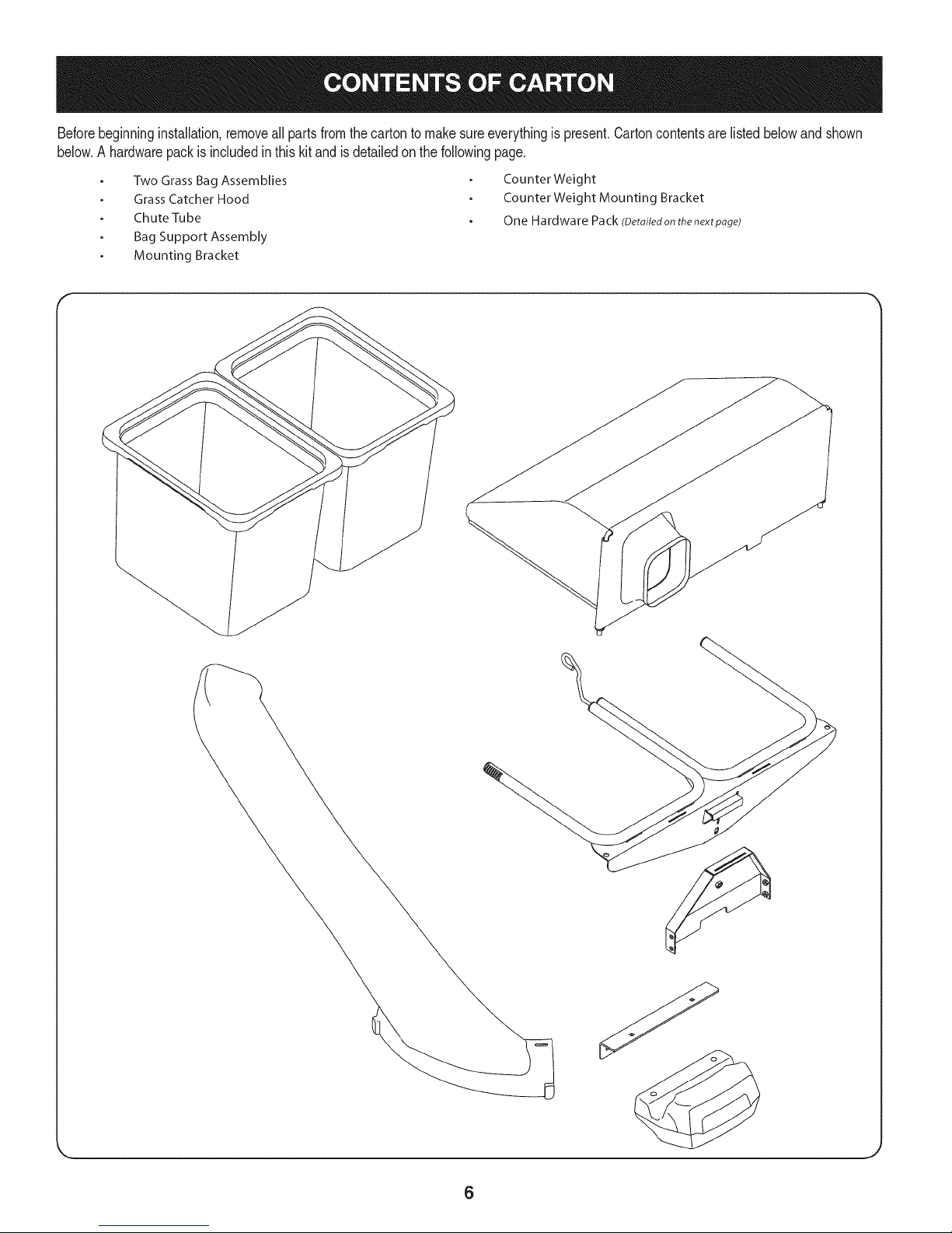
Beforebeginninginstallation,removeall partsfromthe cartonto makesureeverythingispresent.Cartoncontentsarelistedbelowand shown
below.A hardwarepackis includedinthis kitand isdetailedonthe followingpage.
Two Grass Bag Assemblies
Grass Catcher Hood
Chute Tube
Bag Support Assembly
Mounting Bracket
CounterWeight
Counter Weight Mounting Bracket
One Hardware Pack (Detailedonthe nextpage)
6
Page 7
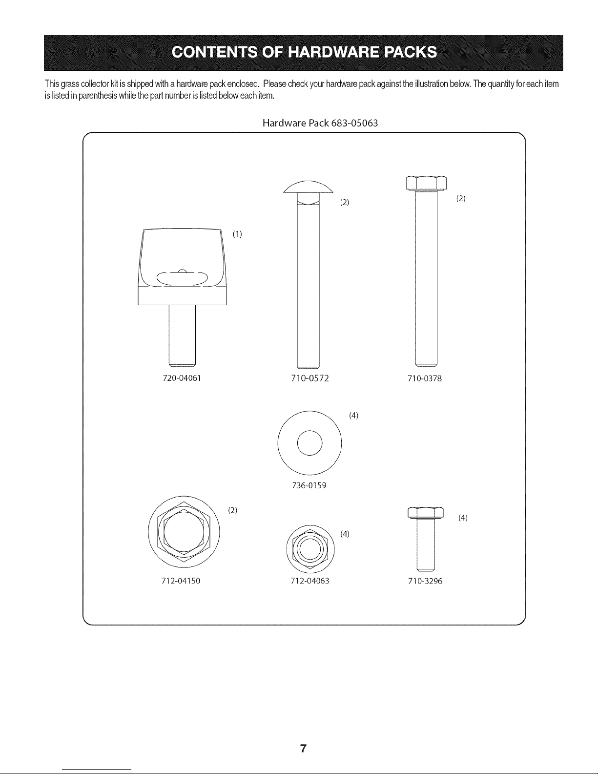
Thisgrasscollectorkitisshippedwithahardwarepackenclosed.Pleasecheckyourhardwarepackagainsttheillustrationbelow.Thequantityforeachitem
islistedinparenthesiswhilethepartnumberislistedbeloweachitem.
Hardware Pack 683-05063
L
720-04061
(1)
710-0572
(2)
(2)
710-0378
(4)
_/ (2)
712-04150
736-0159
712-04063
7
(4)
(4)
710-3296
Page 8
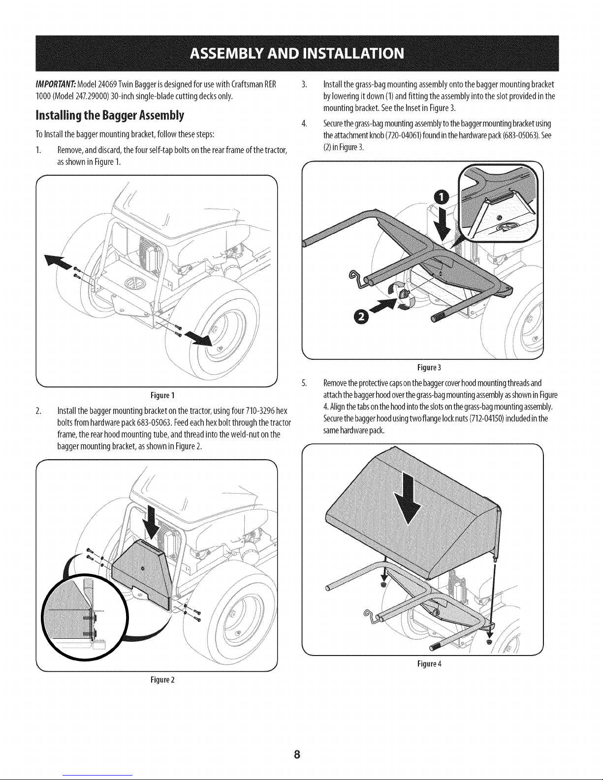
IMPORTAN_Model24069TwinBaggerisdesignedfor usewith CraftsmanRER
1000(Model247.29000)30-inchsingle-bladecuttingdecksonly.
Installing the BaggerAssembly
ToInstallthebaggermountingbracket,followthesesteps:
1. Remove,anddiscard,thefourself-tapboltsontherearframeofthetractor,
asshowninFigureI.
/
Figure1
Installthe baggermountingbracketonthetractor,usingfour710-3296hex
boltsfromhardwarepack683-05063.Feedeachhexboltthroughthetractor
frame,therearhoodmountingtube,andthreadintotheweld-nutonthe
baggermountingbracket,asshowninFigure2.
Installthegrass-bagmountingassemblyontothebaggermountingbracket
byloweringit down(1)andfitting theassemblyintotheslotprovidedinthe
mountingbracket.Seethe Insetin Figure3.
Securethegrass-bagmountingassemblytothebaggermountingbracketusing
theattachmentknob(720-04061)foundinthehardwarepack(683-05063).See
(2)inFigure3.
Figure3
Removetheprotectivecapsonthebaggercoverhoodmountingthreadsand
attachthebaggerhoodoverthegrass-bagmountingassemblyasshownin Figure
4.Alignthetabsonthehoodintotheslotsonthegrass-bagmountingassembly.
Securethebaggerhoodusingtwoflangelocknuts(712-04150)includedinthe
samehardwarepack.
Figure2
Figure4
8
Page 9

6.
Installthebagsontothemountingframeasshownin Figure5.Simplyplace
theleadingedgeofthebagontothefrontframerail,thenrockthebag
backwardsanddownintoplace.Repeatforthesecondbag.
FigureS
Removethedischargechute,ormulchplug.Retainthewingknobsfor
installationofdeckchutein step10.
8.
Insertthechutetubethroughthegrass-catcherhood,in theopening
provided.Itiseasiesttofeedtheendofthetubeintotheopeningwith the
chutetubeflippedupsidedown,thenrotatingright-sideonceinsertedinto
thehood.SeeFigure6.
9. Mountthebaggerchutetubetothedeckofthetractorbyloweringthechute
tubeoverthemountingboltsinthemowingdeck,asshownin Figure7.
10. Securetherearmountingbolt with awingknob(1),thenthefrontmounting
boltwith anotherwingknob(2)asshowninFigure7.
\
Figure7
Figure6
9
Page 10

Assembliagand Installiagthe Counter-Weight
Assemble,thenattachthecounter-weighttothefrontsteeringassemblyusingthe
hardwarein pack683-05063,asshownin Figure8andFigure10.
1. Installthecounter-weightmountingbracketto thecounter-weightusing
two710-0572carriagebolts,two 736-0159flat washersandtwo712-04063
flangelocknutsfrom hardwarepack683-05063.SeeFigure8.
@
Securetheweightbarassemblytothetractorusingtwo710-0378hex
bolts,two736-0159flat washersandtwo712-04063flangelocknutsfrom
hardwarepack683-05063.
Note:Usethetopholesonthetractorframe.
Figure8
Removethebumperfromthetractorbyremovingthetwotapscrewsthat
secureit, asshownin Figure9.
Note:Thebumpermayberetainedfor laterusein thecaseinwhichthe
baggerisremoved.
o
Figure9
10
Page 11

BaggerUsage
NOTE:Whenbothgrassbagsarefull,placethetractoronafirm,levelsurface,
disengagethe PTO,turnthetractorengineoffandsettheparkingbrake.
1. Openthegrassbagcoverbylifting thelowerrearofthecoverandpivotingit
upwards.It isnotnecessaryto removethedischargechuteinordertoempty
thegrassbags.SeeFigure11.
Toreinstallthegrassbags,inserttheleadingedgeontothebaggermount
assembly(1inFigure12),andpivotthegrassbagrearwardanddownas
shownin2ofFigure12.
Figure12
5. Closethegrassbagcover,restartyourtractorandresumecuttingyourgrass.
Figure11
Removethegrassbagsbylifting uptherearsideofthe bagandmovingthe
bagsawayfromthebagsupportassembly.
Emptythegrassclippingsataproperdisposalsite.Holdingthebagfirmly,
turnupsidedown,andemptythecontents.
11
Page 12

12
@
13
Page 13

!
Ref, I Part Number
1. 964-04167
2. 683-04771-0637
3. 683-04772-0637
4. 683-04775-0637
S. 683-04781A-0637
6. 710-0378
7. 710-0572
8. 710-3296
9. 712-04063
10. 712-04150
11. 720-04061
12. 926-0100
13. 731-09227
14. 731-09351
15. 735-0246A
16. 936-0159
17. 764-04148A
18. 783-08135-0637
Description
Grass Bag
Front Hood Assembly Frame
Rear Hood Assembly Frame
Bagger Support Assembly
Mounting Bracket
Hex Lock Screw, 5/16-18, 2.50
Carriage Bolt, 5/16-18, 2.50
Hex Head Screw, 1/4-20, .750
Flange Lock Nut, 5/16-18
Flange Lock Nut, 1/2-13
Knob, 3/8-16, .875
Push Cap, 3/8 Rod
Weight
Chute Tube
Plug End
Flat Washer, .349 x .879 x .063
Grass Catcher Hood
Weight Mounting Bracket
13
Page 14

Garantia ........................................................................ 14
Medidas importantes de seguridad ............................. 15
Gu_a pendiente de ........................................................ 17
Contenido de la caja y paquetes de hardware ..............18
Montaje e Instalaci6n ................................................... 20
operaci6n de ............................................................... 23
Lista de piezas ............................................................ 12
Craftsman Un ASo De Garantia
Duranteun aSodesdelafechadecompra,esteproductoest&garantizadocontracualquierdefectode materialeso manodeobra.Unproducto
defectuososer&reemplazadodeformagratuita.
Paralosdetallesde lacoberturadegarantiaparaobtenerunreemplazogratis,visiteel sitioweb:www.craftsman.com
Estagarantianocubre lasasambleasdel recogedorde cesped,quesonpiezasfungiblesquese desgastendebidoal usonormal
dentrodelperiododegarantia.
Estagarantiaes inv&lidasiesteproductoseutilizamientrasquela prestaci6nde servicioscomercialeso si se alquilaa otra persona.
Estagarantiale otorgaderechoslegalesespecificos,y ustedtambi_npuedetenerotrosderechosquevariandeestadoaestado.
Sears Brands Management Corporation, Hoffman Estates, IL 60179
© SearsBrands,LLC 14
Page 15

Lapresenciadeeste sirnboloindicaque setratade instrucciones
irnportantesde seguridadquese debenrespetarparaevitar
ponerenpeligrosuseguridadpersonaly/omaterialy lade otras
personas.Leay sigatodaslasinstruccionesdeestemanualantes
de poneren funcionarnientoestarn_quina.Si no respetaestas
instruccionespodriaprovocarlesionespersonales.Cuandoveaeste
sirnbolo,ipresteatenci6na la advertencia!
Estarn&quinarueconstruidaparaseroperadadeacuerdocon
lasreglasde seguridadcontenidasenestemanual.AIigualque
concualquiertipodeequipornotorizado,undescuidooerrorpor
partedeloperadorpuedeproducirlesionesgraves.Estarn&quina
escapazde arnputarrnanosy piesy dearrojarobjetoscongran
fuerza.Deno respetarlasinstruccionesde seguridadsiguientesse
puedenproducirlesionesgraveso larnuerte.
PROPOSICION 65 DE CALIFORNIA
Elescapedel motordeesteproducto,algunosde suscornponentes
y algunoscornponentesdelvehiculocontieneno liberansustancias
quirnicasqueelestadodeCaliforniaconsideraque puedenproducir
c_ncer,defectosdenacirnientouotrosproblernasreproductivos.
Losbornesdela bateriay los accesoriosalinescontienenplornoy
cornpuestosdeplorno,sustanciasquirnicasque segOnIoestableci-
do potel Estadode Californiacausanc_ncery da_osenel sisterna
reproductivo.Ldveselasmanos despu_sdeestaren contacto
con estoscomponentes.
Fundonamiento general
1. Lea, comprenda y respete todas las instrucciones que figuran
en el equipo yen los manuales antes de intentar armarlo y
hacerlo funcionar. Guarde este manual en un lugar seguro
para consultas futuras y peri6dicas, asi como para solicitar
repuestos.
2. Para ayudar a evitar una lesi6n pot contacto con las cuchillas
o con un objeto que sea arrojado, mantenga a las personas
que observan, a los ayudantes, ni_os y mascotas alejados a no
menos de 25 metros de la m_quina mientras est& funcionando.
Detenga la m&quina si alguien entra en la zona.
3. Revise minuciosamente el _irea donde se va a usar el equipo.
Retire todas las piedras, palos, cables, huesos, juguetes y otros
objetos extra_os que podrian set recogidos y arrojados por la
acci6n de las cuchillas. Los objetos arrojados por la m&quina
pueden causar lesiones graves.
4. Para protegerse los ojos, utilice siempre galas o lentes de
seguridad mientras opera la m&quina o mientras la ajusta
o repara. Los objetos arrojados que rebotan pueden causar
lesiones oculares graves.
5. Nunca opere la cortadora de c_sped sin tenet bien colocada
la cubierta de descarga o el colector de c6sped. Si falta o
est_ da_ada la cubierta de descarga oun componente del
accesorio embolsador puede resultar en lesiones por contacto
con la cuchilla o con objetos arrojados.
6. No ponga las manos ni los pies cerca de las piezas rotatorias ni
debajo de la plataforma de corte. El contacto con las cuchillas
puede resultar en la amputaci6n de una mano o pie.
7. Apague el motor de la cortadora de c_sped y espere que
las cuchillas se detengan totalmente antes de desbloquear
la abertura de descarga de la cortadora o las piezas de la
embolsadora.
Su responsabilidad--Restrinja elusode estarn_quina
rnotorizadaalas personasquelean,cornprendany respetenlas
advertenciase instruccionesqueaparecenen estemanualyen la
rn_quina.
iGUARDEESTASINSTRUCCIONES!
8. Reduzca la velocidad antes de girar. Opere la m&quina de
forma pareja. Evite el funcionamiento err_itico y la velocidad
excesiva. Tenga en cuenta que el accesorio colector de c6sped
puede afectar las caracteristicas de manejo de su cortadora.
Fundonamiento en pendientes
Las pendientes son un factor importante en los accidentes
ocasionados pot p_rdida de control y vuelcos que pueden causar
lesiones graves e incluso la muerte. Los accesorios tambien pueden
afectar la estabilidad de la m&quina. La operaci6n en pendiente
requiere mayor precauci6n.
Para seguridad, use el medidor de pendientes que se incluye como
parte de este manual para estimar el _ingulo de la pendiente antes
de hacer funcionar la m_iquina en una zona inclinada. Si la pendiente
es mayor a 10 grados en el medidor, no opere la cortadora con el
accesorio embolsador en ese sector, pues podria causar lesiones
graves.
I-lagaIosiguiente:
1. Corte hacia arriba y abajo de las pendientes, no en forma
transversal. Tenga sumo cuidado al cambiar de direcci6n en
una pendiente.
2. Est_ atento a los hoyos, surcos, baches, rocas, u otros objetos
ocultos. El terreno desnivelado puede voltear la m&quina. El
pasto alto puede ocultar obst_iculos.
3. Conduzca a baja velocidad. Elija una velocidad Io
suficientemente baja como para no tener que detenerse
o cambiar de marcha mientras est,1 en la pendiente. Los
neum_ticos pueden perder tracci6n en las pendientes aun
cuando los frenos funcionen correctamente. Mantenga
la m&quina siempre en velocidad cuando desciende una
pendiente, para poder frenar con el motor.
15
Page 16

4. Sigalas recomendaciones del fabricante sobre pesos y
contrapesos de las ruedas,para mejorar laestabilidad.
5. Haga que todos losmovimientos en las pendientes sean
lentos y graduales. No cambie repentinamente lavelocidad
ni ladirecci6n. Un frenado ocambio de velocidad repentinos
pueden causar que el frente de la m_quina selevante y d6 una
voltereta hacia atr_s, Io que podria causar lesiones graves.
6. Evite arrancar o detenerse en una pendiente. Silos neum_ticos
pierden tracci6n, desenganche las cuchillas y descienda
lentamente la pendiente.
Nohaga I0siguiente:
I. No gire en una pendiente a menos que sea imprescindible. De
ser posible, gire lenta y gradualmente cuesta abajo.
2. No corte el c_sped cerca de barrancos, zanjas o terraplenes. La
cortadora de c_sped podria volcarse repentinamente si una de
las ruedas estuviera sobre el borde de un acantilado o zanja, o
si un borde se desmoronara.
3. No intente estabilizar la m_quina poniendo el pie en el suelo.
4. No utilice un colector de c_sped en pendientes empinadas.
5. No corte el c_sped humedo. Una reducci6n en tracci6n puede
causar derrapes.
Servki0 general
I. Antes de limpiar, reparar o inspeccionar la m_quina,
compruebe que las cuchillas y todas las piezas m6viles se
hayan detenido. Desconecte el cable de la bujia y p6ngalo
haciendo masa contra el motor para evitar que arranque
accidentalmente.
2. Mantenga todas las tuercas, pernos y tornillos bien ajustados
para asegurarse de que el equipo est_ en condiciones seguras
de operaci6n.
3. Nunca intente violar el sistema de bloqueo de seguridad u
otros mecanismos de seguridad de la cortadora. Controle
peri6dicamente que funcionan correctamente.
4. No intente nunca hacer ajustes o reparaciones a la cortadora
mientras el motor est_ en marcha.
5. Los componentes del colector de c6sped y la cubierta de
descarga est_n sujetos a desgaste y daffos que podrian dejar
expuestas piezas que se mueven o permitir que se arrojen
objetos. Para proteger su seguridad, verifique frecuentemente
todos los componentes y reempl_celos inmediatamente
0nicamente con piezas de los fabricantes del equipo original
(O.E.M.) indicados en este manual. El uso de piezas que no
cumplen con las especificaciones del equipo original puede
resultar en rendimiento inadecuado y puede poner en peligro
la seguridad.
6. Mantenga o reemplace las etiquetas de seguridad y de
instrucciones segun sea necesario.
Simbolosde seguridad
En esta p_gina se presentan y describen los simbolos de seguridad que pueden aparecer en este producto. Lea, entienda y cumpla todas las
instrucciones incluidas en la m_quina antes de intentar armarla y utilizarla.
LEA LOS MANUALES DEL OPERADOR
Lea, entienda y cumpla todas las instrucciones incluidas en los manuales antes de intentar armar la
unidad y utilizarla.
DETENCION
Apague el motor antes de abrir la cubierta de la embolsadora.
IADVERTENCIA! Su responsabilidad--Limiteel usodeestam_.quinamotorizadaalas personasquelean,comprendany
cumplanlasadvertenciaseinstruccionesqueapareceneneste manualyen lam_.quina.
iGLIARDEESTASINSTRL!CCIONES!
16
Page 17

(ACEPTAR)
Figura1
"" 10° Pendiente
10° Pendiente
(DEiVIASlADO ESCARPADO)
Figura2
0oI[nea
- - " "" - _ .-...diSC°ntinua
US0DEESTEPENDIENTEDECALIBREPARADETERiVIINAR
SIUNAPENDiENTEESDEIV1ASiADOESCARPADOPARAUNAOPERACi(_NSEGURA!
Paracomprobarlapendiente,hagaIosiguiente:
1. Borrarestap_.ginay dobleaIo largodelalineadiscontinua.
2.
3.
4.
Localizarun objetoverticalsobreodetrJ.sdelapendiente(unposte,unedificio,unavalla, un _.rbol,etc.)
Alineecadaladodependientedecalibreconelobjetovertical(consultarFigura1andFigura2).
Ajusteel pendientedecalibrearribao haciaabajohastalostoquesesquinaizquierdael pendiente
(consultarFigura1andFigura2).
Sihayun espaciopordebajodela pendientedecalibre,elpendienteesdemasiadoescarpaporoperaciOn
segura(consultarFigura2 above).
Las pendientesson unfactor importante relacionadocon un vuelco y renovaci6nde los accidentesque pueden provocar lesionesgraves o lamuerte.
No utilicela m_.quinaen pendientesde m_.sde 10grados.Todos pendientesrequiere mayorprecauci6n.Si nopuede retrocederen lapendiente o si se
siente inseguroen ella, no larecorte. Siempre corteel cespedarriba y abajo laspendientes, nunca entoda la superficiede lacuesta.
Page 18

Antesdecomenzarlainstalaci6n,quitetodaslaspiezasde lacajaparaasegurarsedeque todoest,.presente.Contenidosdecart6nse
enumeranacontinuaci6nyse muestraacontinuaci6n.Unpaquetedehardwareseincluyeenestekity sedetallaenla p_.ginasiguiente.
o
Dos conjuntos de bolsa de hierba
o
Campana de recogedor de hierba
o
Tubo de conducto
o
Saco de soporte
o
Soporte de montaje
f
o
Peso del contador
o
Soporte de montaje de peso de contador
o
U.np.aquete de Hardware (detallados en la pdgina
slgulente)
18
Page 19

Estekit decespedsesuministraconunpaquetede hardwareincluido.Porfavorrevisesupaquetedehardwareen contradelailustraci6nde
abajo.Lacantidaddecadaarticuloseindicaentrepar_ntesis,mientrasqueelnQmeroaparecedebajodecadaarticulo.
Hardware Pack 683-05063
L
720-04061
(1)
710-0572
(2)
(2)
710-0378
(4)
_/ (2)
712-04150
736-0159
712-04063
19
(4)
(4)
710-3296
Page 20

Instalaci6ndeiconjunto deiaembolsadora 3.
Afin deinstalarlam_nsuladesoportedelaembolsadora,sigaestospasos:
1. Extraigaydesecheloscuatropernosautorroscantesdelbastidortraserodel 4.
tractor,comoseindicaenlaFigura1.
/
Coloqueelconjuntodemontajedelabolsarecolectoradec_spedsobrela
m_nsuladesoportedelaembolsadorabaj_ndola(1)ycolocandoelconjunto
enlaranuraprovistaenlam_nsulasoporte.Veael recuadrodelaFigura3.
Sujeteelconjuntodemontajedelaboisarecolectoradec_spedalam_nsulade
soportedelaembolsadoraconlaperilladesujed6n(720-04061)queseencuentra
enelpaquetedeelementosdeferreter[a(683-05063).Consuite(2)enlaFigura3.
Figure1
Instalela m_nsuladesoportedelaembolsadoraenel tractorconloscuatro
pernoshexagonales710-3015delpaquetedeelementosdeferreteria683-
05063.Pasecadaunodelospernoshexagonalesporelbastidordeltractor,
eltubodemontajedelatapatraserayenr6squelosenlatuercadesoldadura
delam_nsuladesoportedelaembolsadora,comoseindicaenla Figura2.
i
Figure3
Extraigalastapasdeprotecci6ndelasroscasdemontajedelatapadelacubierta
delaembolsadoraycoloquelacubiertadelaembolsadorasobreelconjunto
demontajedelaboisaderecolecd6ndec_spedcomoseindicaenlaFigura4.
Sedebenalinearlasleng_etasdelatapadentrodelasranurasdelconjuntode
montajedelabolsarecolectoradec_sped.Sujetelacubiertadelaembolsadora
condostuercasdeseguridadconbrida(712-04150)queseincluyenenelmismo
paquetedeelementosdeferreter[a.
Figure2
Figure4
2O
Page 21

6,
Coloquelasbolsassobreelbastidordemontajecomoseindicaenla Figura
5.%1odebecolocarel bordeentrantedelabolsasobrelaguiadelbastidor
frontal,luegobalanceelabolsahadaatr,_syhadaabajoparaquequedeen
posid6n.RepitaIomlsmoparalasegundabolsa.
Figure5
7.
Retireeltubodedescarga,oclavijadeabono.Conservelospomosde
mariposaparalainstalad6ndelconductodecublertaenel paso10.
8.
Inserteeltubodelcanalatrav_sdelatapadelcolectordec_sped,enla
aberturaprovlsta.Resultam_sfl_cilsiseintroduceelextremodeltubodentro
delaaberturaconeltubodel canalgiradodemaneraquequededadovuelta,
girandoluegoaladerechadespu_sdeinsertarloenlatapa.VealaFigura6.
9. Monteel tubodelcanaldelaembolsadoraenlaplataformadeltractor
bajandoeltubodelcanalsobrelospemosdemontajedelaplataformade
corte,comoseindicaenla Figura7.
10. Sujeteelpemodemontajetraseroconunaperllladealeta(1),luegoel
pemodemontajedelanteroconotraperilladealeta(2),comose[ndlca
enla Figura7.
Figure7
Figure6
21
Page 22

Montaje e instalaci6n dei contrapeso
Elcontrapesosedebemontarenelconjuntodeladirecddndelanterosujet_ndolo
conloselementosdeferreteriadel paquete683-05063,comoseindicaenla Figura
8y laFiguraI0.
I. Instalela m_nsuladesoportedelcontrapesoenelcontrapesocondospernos
decarro710-0572,dosplanas736-0159ydostuercasdeseguridadconbrida
712-04063delpaquetedeelementosdeferreteria683-05063.Consultela
Figura8.
I
Sujeteelconjuntodelabarradepesoaltractorcondospernoshexagonales
710-0378,dosarandelasplanas736-0159ydostuercasdeseguridadcon
brida712-04063del paquetedeelementosdeferreteria683-05063.
Nora:Uselosorificiossuperioresenel marcodeltractor.
0
Figure 10
Figure8
Extraigaelparagolpesdeltractor.
Not:a:Sepuedeconservarel paragolpesparausosposterioresencasoquese
extraigalaembolsadora
o
Figure9
22
Page 23

Usode ia embolsadora
NOTA:Unavezqueest_nllenasambasbolsarecolectorasdec_sped,coloqueel
tractorensuelofirmeynivelado,desactivelaPTO,apagueelmotordeltractory
pongaelfrenodemano.
I. Abralacubiertadelabolsarecolectoradec_spedlevantandolapartetrasera
inferiordelacubiertaygir_ndolahaciaarriba.Noesnecesarioquitarelcanal
dedescargaa fin devadarlasbolsasrecolectorasdec_sped.VealaFigura11.
Paravolvera [nstalarlasbolsasrecolectorasdec_sped,[nserteel borde
entranteenelconjuntodemontajedelaembolsadora(I delaFlgura12)y
girelabolsarecolectoradec_spedhadaatr_syabajocomoselndlcaen2 de
laFigura12.
Figure12
5. Cierrelacubiertadelabolsarecolectoradec_sped,reinideeltractory
retomeelcortedelc_sped.
Figure11
Extralgalasbolsasrecolectorasdec_spedlevantandolapartetraseradela
bolsayalejandolasbolsasdelconjuntodesoportedelasbolsas.
Vacielosrecortesdec_spedenunlugaradecuadoparadesecharlos.
Sosteniendolabolsaconfirmeza,d_lavueltayvacieelcontenido.
23
Page 24

Thispageintentionallyleftblank.
24
 Loading...