

Page 1

perator's
I:RnFrSMRN°
THREE BiN BAGGER
Model No. 247.24020
• Espanol, p. 18
iMPORTANT:
Read and follow all Safety
Rules and instructions before
operating this equipment.
Sears Brands Management Corporation, Hoffman Estates, IL 60179 U.S.A.
Visit our website: www.sears.com/craftsman FormNo.769-0%34A
For answers to your questions about
this product, Call:
1-800=659=5917
CraftsmanTractorHelpLine
7 am = 7 pm CT, Mort. =Sun.
(January28,2010)
Page 2

Safe Operation Practices .............................................. 3-4
Slope Guide ....................................................................... 5
Contents of Carton & Hardware Packs .......................... 6-7
Assembly and Installation ............................................ 8-14
Operation ........................................................................ 14
Parts List .................................................................... 16-17
Espa_ol ............................................................................ 18
Service Numbers ............................................. Back Cover
Craftsman Full Warranty
IfthisCraftsmanproductfailsdueto a defectinmaterialor workmanshipwithinoneyearfromthedateof purchase,returnittoany Searsstoreor
otherCraftsmanoutletinthe UnitedStatesforfreereplacement.
ThiswarrantycoversONLYdefectsinmaterialandworkmanship.SearswillNOTpayfor:
• Replacementofbags,whichareexpendableitemsthatcan wearoutfromnormalusewithinthewarrantyperiod.
• Repairsnecessarybecauseof accidentorfailuretooperateor maintaintheproductaccordingtoall suppliedinstructions.
Thiswarrantyappliesforonly 90daysifthis productis everusedforcommercialor rentalpurposes.
Thiswarrantyappliesonlywhilethisproductis usedinthe UnitedStates.
Thiswarrantygivesyouspecificlegalrights,andyou mayalsohaveotherrightswhichvaryfromstateto state.
Sears, Roebuckand Co., Hoffman Estates, IL 60179
© SearsBrands,LLC 2
Page 3

Thissymbolpointsout importantsafetyinstructionswhich,if not
followed,couldendangerthepersonalsafetyand/orpropertyof
yourselfandothers. Readandfollowallinstructionsin thismanual
beforeattemptingto operatethismachine.Failuretocomplywith
theseinstructionsmayresultin personalinjury.Whenyou seethis
symbol,HEEDITSWARNING!
Thisattachmentwas builttobe usedaccordingtothe safeopera-
tionpracticesinthis manual.Carelessnessor erroronthepartof
theoperatorcanresultin seriousinjury.Mowersarecapableof
amputatinghandsandfeetandthrowingobjects.Failuretoobserve
thefollowingsafetyinstructionsaswellastheinstructionsprovided
withyourmower,couldresultin seriousinjuryordeath.
CALIFORNIA PROPOSITION 65
EngineExhaust,someof itsconstituents,andcertainvehicle
componentscontainoremitchemicalsknowntoStateof California
tocausecancerandbirthdefectsorotherreproductiveharm.
Batteryposts,terminals,and relatedaccessoriescontainleadand
leadcompounds,chemicalsknowntotheStateof Californiato
causecancerandreproductiveharm.Washhandsafterhandling.
GENERAL OPERATION
• Read,understand,and followall instructionsonyourequipmentand
intheir manualsbeforeattemptingtoassembleand operate.Keepthis
manualina safe placeforfutureand regularreferenceandfor ordering
replacementparts.
,, Tohelpavoidbladecontactora thrownobjectinjury,keepbystanders,
helpers,childrenand petsat least75feetfromthe mowerwhile itis in
operation.Stopmachineif anyoneentersthe area.
,, Thoroughlyinspectthe areawherethe equipmentisto beused.Remove
allstones,sticks,wire,bones,toys,and otherforeignobjectswhich
couldbepickedupandthrownbythe blade(s).Thrownobjectscan
causeseriouspersonalinjury.
,, Alwayswearsafetyglassesor safetygogglesduringoperationand while
performinganadjustmentorrepairtoprotectyoureyes.Thrownobjects
whichricochetcancauseseriousinjurytothe eyes.
,, Donotoperatethe mowerwithoutthe dischargecoveror entiregrass
catcherinits properplace.Amissingor damageddischargecoveror
grassbagattachmentcomponentmayresultinthrownobjectsor blade
contactinjuries.
,, Donotputhandsorfeet nearrotatingpartsor underthecuttingdeck.
Contactwiththe blade(s)canamputatehandsandfeet.
Your Responsibility--Restrict theuseof this powermachineto
personswhoread,understandandfollowthewarningsandinstruc-
tionsin thismanualandonthemachine.
SAVE THESE INSTRUCTIONS!
,, Shutoffmower'sengineand waitfor bladestocometo a completestop
beforeuncloggingmower'sdischargeopeningor baggerparts.
,, Slowdownbeforeturning.Operatethe machinesmoothly.Avoiderratic
operationandexcessivespeed.Beawarethata grasscatcherattach-
mentcanaffectthehandlingcharacteristicsof your mower.
,, Disengageblade(s),set parkingbrake,stopengineandwaituntilthe
blade(s)cometo a completestop beforeopeningbaggerattachment's
top cover,removinggrasscatcher,emptyinggrass,uncloggingchute,
removinganygrass ordebris,or makinganyadjustments.
,, Neverleavearunningmachineunattended.Alwaysturn offblade(s),
placetransmissionin neutral,set parkingbrake,stopengineandremove
keybeforedismounting.
,, Yourmachineisdesignedtocut normalresidentialgrassofa heightno
morethan10".Do notattemptto mowthroughunusuallytall,dry grass
(e.g.,pasture)or pilesofdry leaves.Drygrass orleavesmaycontact
the engineexhaustand/or builduponthe mowerdeckpresentinga
potentialfirehazard.
,, If situationsoccurwhichare notcoveredinthis manual,usecareand
goodjudgment.Contact1-800-659-5917forassistance.
3
Page 4
SLOPE OPERATION
Slopesare a majorfactorrelatedto lossofcontrolandtip-overaccidents
whichcan resultinsevereinjuryordeath.Attachmentscanalsoaffectthe
stabilityofthe machine.All slopesrequireextracaution.
Foryoursafety,usethe slopeguideincludedas partofthis manualto
estimatetheangle of slopesbeforeoperatingthismachineona slopedorhilly
area.Iftheslope isgreaterthan 10degreesas shownonthe slopeguide,do
notoperatethemowerwiththe grass bagattachmentinstalledonthat areaor
seriousinjurycouldresult.
DO:
1. Mowupanddownslopes,not across.Exerciseextremecautionwhen
changingdirectiononslopes.
2. Watchforholes,ruts,bumps,rocks,or otherhiddenobjects.Uneven
terraincouldoverturnthe machine.Tallgrasscan hideobstacles.
3. Useslowspeed.Choosea lowenoughspeedsetting sothatyou will not
haveto stopor shift whileonthe slope.Tiresmaylosetractiononslopes
eventhoughthe brakesarefunctioningproperly.Alwayskeepmachine
in gearwhengoingdownslopesto takeadvantageofenginebraking
action.
4. Followthemanufacturer'srecommendationsfor wheelweightsor
counterweightsto improvestability.Forrecommendations,contact
1-800-659-5917.
5. Keepall movementontheslopesslowandgradual.Do notmakesud-
denchangesin speedordirection.Rapidengagementor brakingcould
causethefrontof the machineto liftand rapidlyflip overbackwards
whichcouldcauseseriousinjury.
6. Avoidstartingor stoppingon a slope.Iftires losetraction,disengagethe
blade(s)andproceedslowlystraightdowntheslope.
DO NOT:
1. Do notturnon slopesunlessnecessary;then,turnslowlyandgradually
downhill,ifpossible.
2. Donotmowneardrop-offs,ditchesor embankments.Themowercould
suddenlyturnoverif a wheelisoverthe edgeof a cliff,ditch,or if an
edgecavesin.
3. Donottry tostabilizethe machinebyputtingyourfooton theground.
4. Donotusea grasscatcheronsteepslopes.
5. Donotmowonwet grass. Reducedtractioncouldcausesliding.
GENERAL SERVICE
1. Beforecleaning,repairing,or inspecting,makecertainthe blade(s)
andall movingparts havestopped.Disconnectthe sparkplugwireand
groundagainsttheenginetopreventunintendedstarting.
2. Keepallnuts,bolts,andscrewstightto besurethe equipmentis in safe
workingcondition.
3. Nevertamperwith yourmower'ssafetyinterlocksystemor othersafety
devices.Checktheirproperoperationregularly.
4. Neverattemptto makeadjustmentsor repairswhilethemower'sengine
is running.
5. Grasscatchercomponentsandthe dischargecoveraresubjectto wear
anddamagewhichcouldexpose movingpartsor allowobjectsto be
thrown.Forsafetyprotection,frequentlycheckcomponentsandreplace
immediatelywith originalequipmentmanufacturer's(O.E.M.)partsonly,
listedinthis manual.Useof partswhichdonot meettheoriginalequip-
mentspecificationsmayleadto improperperformanceandcompromise
safety!
6. Maintainor replacesafetyand instructionlabels,asnecessary.
SAFETY SYMBOLS
This section depicts and describes safety symbols that may appear on this product. Read, understand, and follow allinstructions on the machine
before attempting to assemble and operate.
READTHEOPERATOR'SMANUAL(S)
I
I
Read,understand,andfollowall instructionsinthe manual(s)beforeattemptingtoassembleand
operate
STOP
Turnoffthe enginebeforeopeningthe baggercover.
4
Page 5
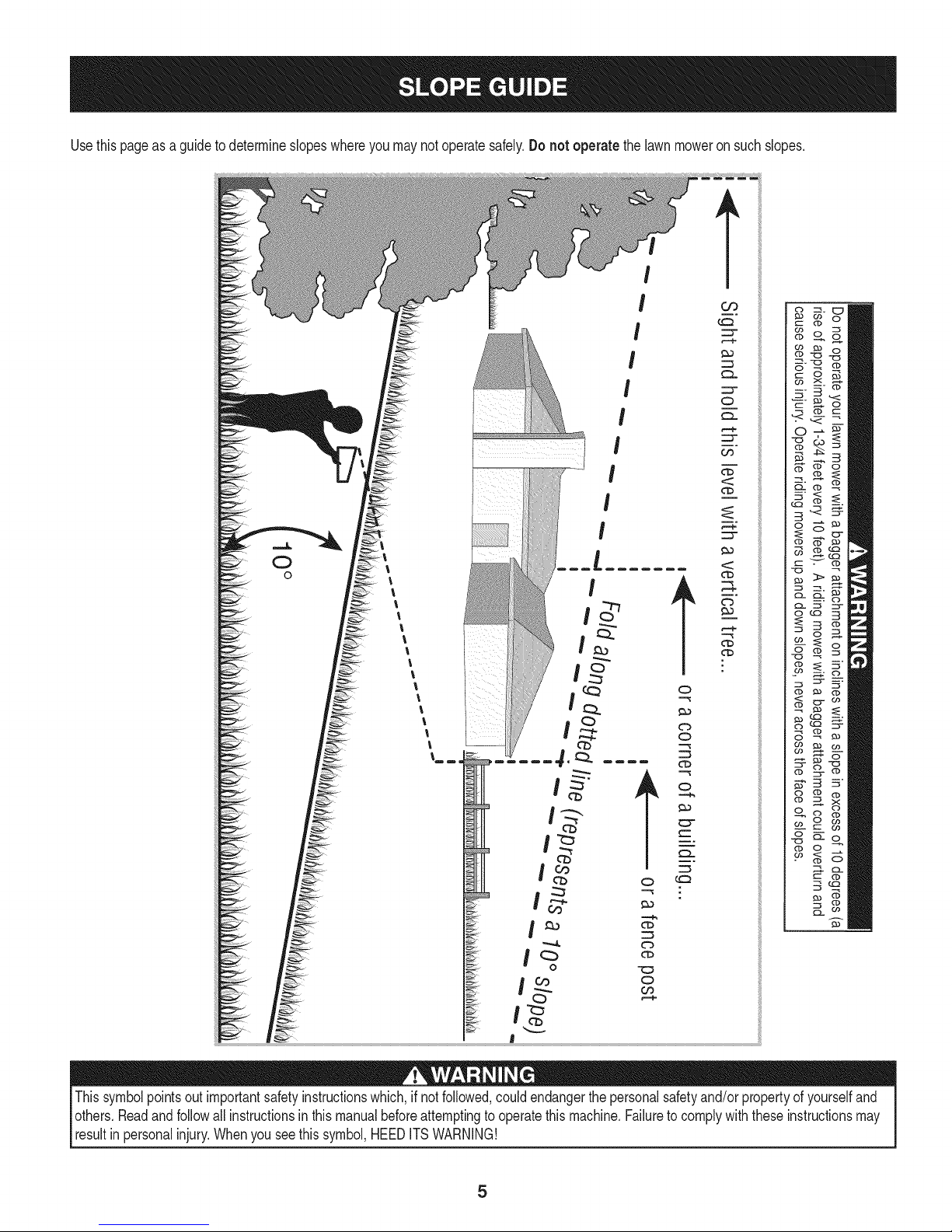
Usethispageasa guidetodetermineslopeswhereyoumaynotoperatesafely.Donot operatethe lawnmoweron suchslopes.
0
o
Thissymbolpointsoutimportantsafetyinstructionswhich,if not followed,couldendangerthepersonalsafetyand/orpropertyofyourselfand
others.Readandfollowallinstructionsinthis manualbeforeattemptingto operatethismachine.Failureto complywiththeseinstructionsmay
resultinpersonalinjury.Whenyouseethissymbol,HEEDITSWARNING!
Page 6
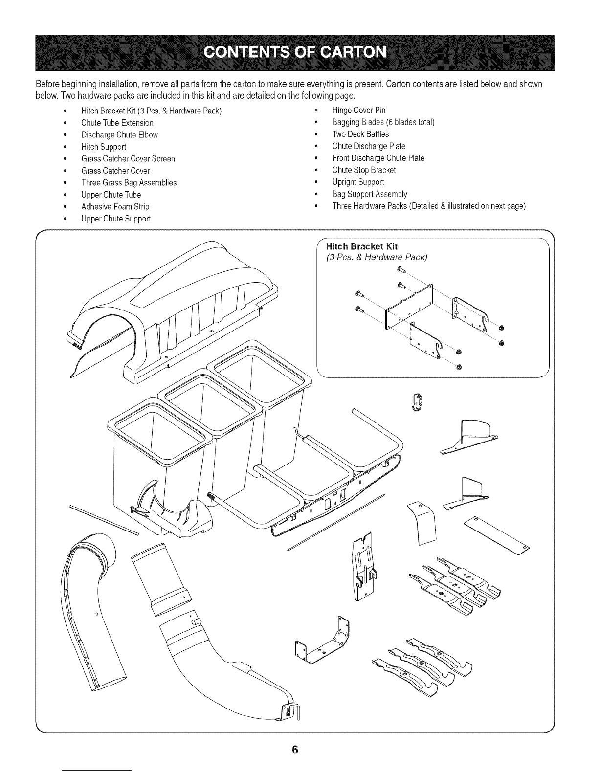
Beforebeginninginstallation,removeallpartsfromthecartontomakesureeverythingispresent,Cartoncontentsarelistedbelowandshown
below.Twohardwarepacksareincludedinthiskitandaredetailedonthefollowingpage.
• HitchBracketKit(3 Pcs.& HardwarePack) • HingeCoverPin
• ChuteTubeExtension • BaggingBlades(6 bladestotal)
• DischargeChuteElbow • TwoDeckBaffles
• HitchSupport • ChuteDischargePlate
• GrassCatcherCoverScreen • FrontDischargeChutePlate
• GrassCatcherCover • ChuteStop Bracket
• ThreeGrassBagAssemblies • UprightSupport
• UpperChuteTube • BagSupportAssembly
• AdhesiveFoamStrip • ThreeHardwarePacks(Detailed& illustratedon nextpage)
• UpperChuteSupport
_Hitch Bracket Kit
(3 Pcs. & Hardware Pack)
\
J
6
Page 7

Thisgrasscollectorkitis shippedwith threehardwarepacksenclosed, Pleasecheckyourhardwarepacksagainsttheillustrationsbelow,The
quantitiesforeachitemis listedin parenthesiswhilethe partnumberislistedneareachitem.
Hardware included with 689-00084 Hardware Pack689-00163
71o-3oo8
710-3008
1) )
710-0276
712-04063
Hardware Pack 689-00087
I
©
(1)
(3)
712-04065
(3)
712-04064
(2)
(2)
I
726-3046
712-04063
(4)
711-0309A
714-0117
1)
710-3015
C
'_' (2)
71o-o4484
723-0476
(1)
' _=_(3')
710-3168
7
Page 8
NOTE:Referencesto left, right,frontandrearofthetractorarefrom
theoperator'sposition,unlessotherwisestated.
• Beforeassembly,placethetractoronafirm,levelsurface,
disengagethe PTO,stopthetractorengineandsetthe parking
brake.
Forconvenience,pivotthe seatforwardandleaveit inthatposi-
tionuntilthegrasscollectorisfullymountedandassembled.
AssembleMounting Brackets
Toassemblethebaggermountingassembly,locatethemounting
assemblypackandfollowthesesteps:
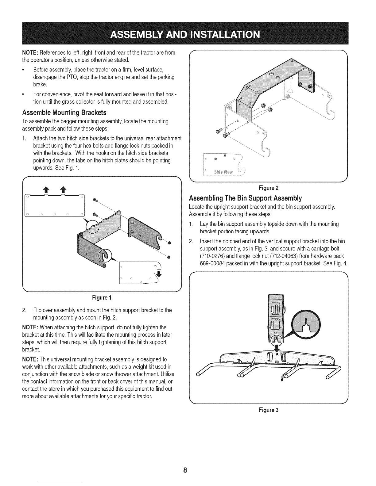
1. Attachthetwo hitchsidebracketstotheuniversalrearattachment
bracketusingthefourhexboltsandflange locknutspackedin
withthebrackets.Withthehookson thehitchsidebrackets
pointingdown,thetabsonthe hitchplatesshouldbe pointing
upwards.SeeFig.1.
0 /
/
Figure2
Assembling The Bin Support Assembly
Locatetheuprightsupportbracketandthebinsupportassembly.
Assembleit byfollowingthesesteps:
1. Laythebinsupportassemblytopsidedownwiththemounting
bracketportionfacingupwards.
2. Insertthe notchedendoftheverticalsupportbracketintothebin
supportassembly,asin Fig.3,and securewitha carriagebolt
(710-0276)andflangelocknut (712-04063)fromhardwarepack
689-00084packedin withtheuprightsupportbracket.SeeFig.4.
Figure1
2. Flipoverassemblyandmountthehitchsupportbrackettothe
mountingassemblyasseenin Fig.2.
NOTE:Whenattachingthehitchsupport,donotfullytightenthe
bracketatthistime.Thiswill facilitatethemountingprocessin later
steps,whichwillthen requirefullytighteningof thishitchsupport
bracket.
NOTE:Thisuniversalmountingbracketassemblyisdesignedto
workwithotheravailableattachments,suchas a weightkitused in
conjunctionwiththe snowbladeor snowthrowerattachment.Utilize
thecontactinformationonthefrontorbackcoverofthis manual,or
contactthestorein whichyoupurchasedthisequipmenttofindout
moreaboutavailableattachmentsforyourspecifictractor.
Figure3
8
Page 9
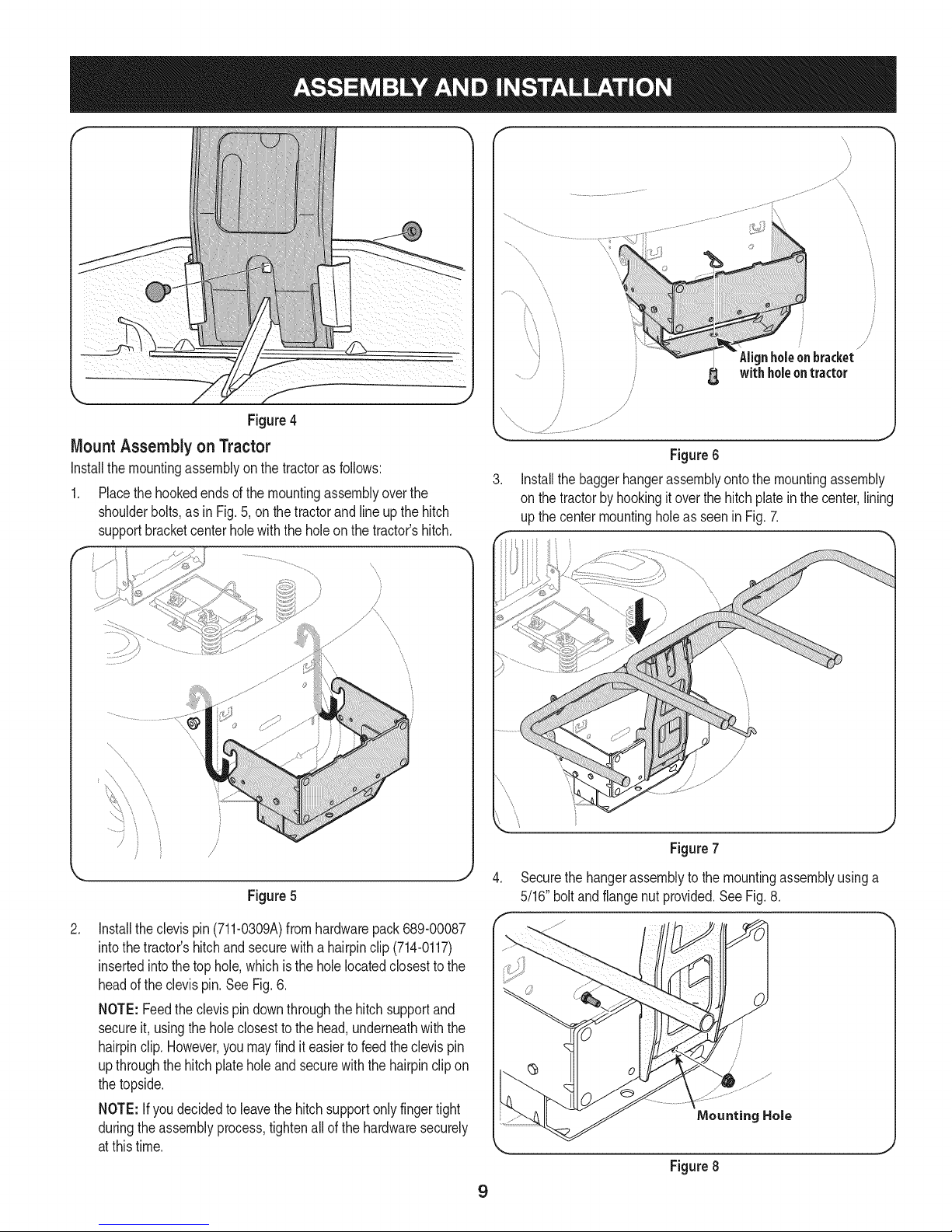
Figure4
Mount Assemblyon Tractor
Installthemountingassemblyonthe tractorasfollows:
1. Placethe hookedendsofthemountingassemblyoverthe
shoulderbolts,asin Fig.5,onthetractorandlineupthehitch
supportbracketcenterholewiththe holeonthetractor'shitch.
f
...........,,
//
_%'_lignholeonbracket_
, /
/
/
/
J
withholeontractor
.,J
Figure6
Installthebaggerhangerassemblyontothe mountingassembly
on thetractorbyhookingitoverthe hitchplateinthecenter,lining
upthecentermountingholeas seeninFig.7.
/
Figure5
.
Installtheclevispin(711-0309A)fromhardwarepack689-00087
intothe tractor'shitchand securewith ahairpinclip(714-0117)
insertedintothetophole,whichisthe holelocatedclosesttothe
headofthe clevispin.SeeFig.6.
NOTE:Feedtheclevispindownthroughthehitchsupportand
secureit, usingtheholeclosestto the head,underneathwiththe
hairpinclip.However,youmayfind iteasiertofeedthe clevispin
upthroughthe hitchplateholeandsecurewiththehairpinclipon
thetopside.
NOTE:Ifyou decidedtoleavethehitchsupportonlyfingertight
duringtheassemblyprocess,tightenallof the hardwaresecurely
atthistime.
Figure7
j
.
Securethehangerassemblytothe mountingassemblyusinga
5/16"boltandflangenutprovided.SeeFig.8.
Figure8
9
Page 10
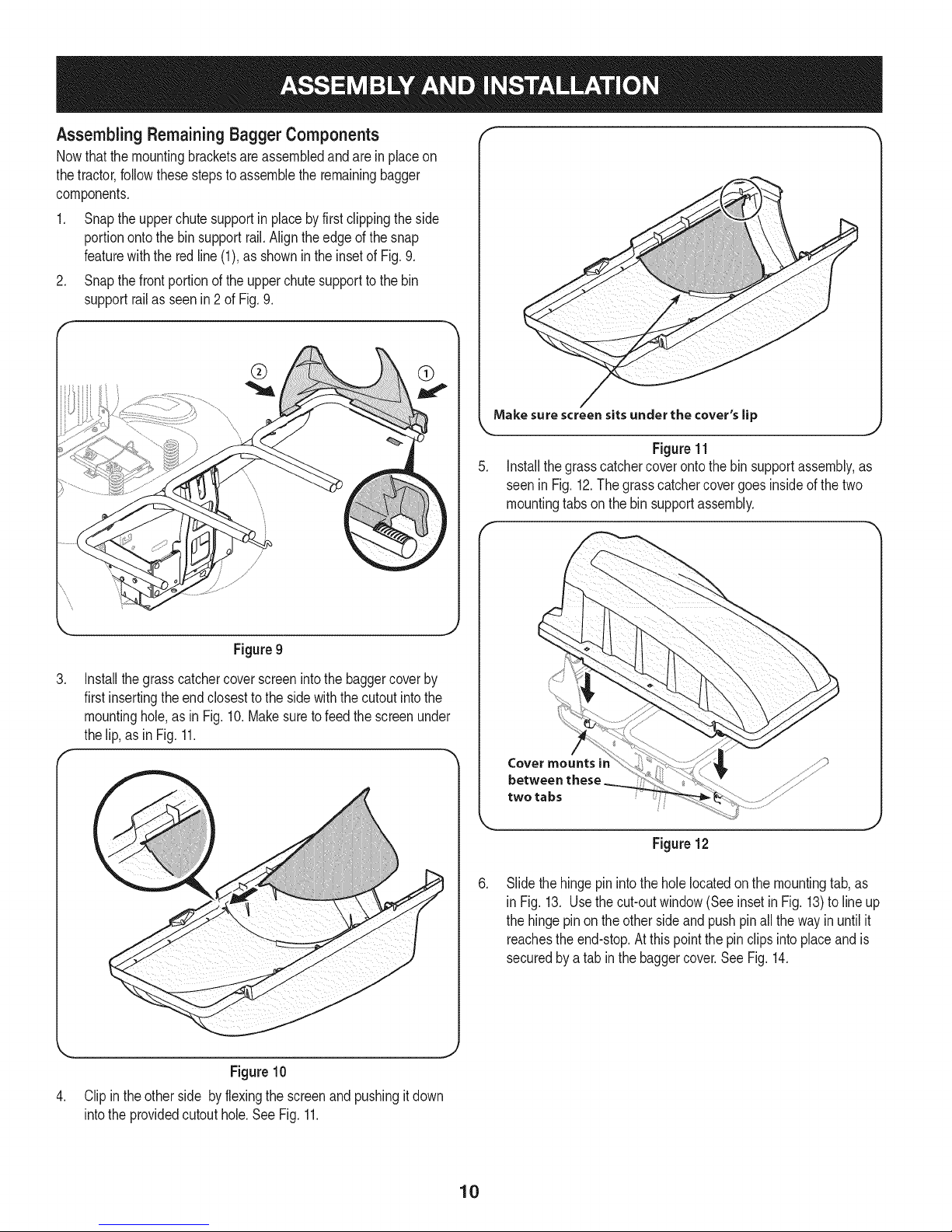
Assembling Remaining Bagger Components
Nowthat themountingbracketsareassembledandare inplaceon
thetractor,followthesestepstoassembletheremainingbagger
components.
1. Snaptheupperchutesupportinplaceby firstclippingtheside
portionontothebinsupportrail.Aligntheedgeof thesnap
featurewiththe redline(1),asshownintheinsetof Fig.9.
2. Snapthefrontportionof theupperchutesupporttothebin
supportrailasseen in2 of Fig.9.
Makesurescreensitsunderthe cover'slip
.J
Figure11
5. Installthe grasscatchercoverontothebin supportassembly,as
seeninFig.12.Thegrasscatchercovergoesinsideof thetwo
mountingtabson the binsupportassembly.
Figure9
,
Installthegrasscatchercoverscreenintothebaggercoverby
firstinsertingtheendclosestto the sidewiththecutoutintothe
mountinghole,as inFig.10. Makesuretofeedthescreenunder
thelip,asinFig. 11.
Figure10
,
Clipinthe otherside byflexingthe screenand pushingitdown
intothe providedcutouthole.SeeFig.11.
Cover mounts ir
between these
two tabs
Figure12
,
Slidethehingepinintotheholelocatedonthemountingtab,as
inFig. 13. Usethe cut-outwindow(SeeinsetinFig.13)tolineup
thehingepinonthe othersideandpushpinallthewayinuntilit
reachestheend-stop.Atthis pointthepinclipsintoplaceand is
securedbya tabinthe baggercover.SeeFig. 14.
J
10
Page 11

Hinge Pin
Figure13
8. Installthe grassbinsontothebinsupportassemblybyinserting
thefrontedgeinfirst (1),as seenin Fig.16,andsettingtheback
edgedown(2) untilit fits intotheassembly.
Figure16
Attaching Blades
Alwaysprotectyourhandswhileservicingbladesbywearingheavy
workglovesor usingheavyrags.
!
Figure14
7.
Opengrasscatchercoverby pushinginontherear,right-sidetab
withyourright-hand,asseenin 1of Fig.15,andliftingwithyour
left-handintherearcenter,2.
f
NOTE:Threehigh-liftbaggingbladesareincludedinthegrass-catcher
kit.Replacethebladeswiththesenewbladesandsavethe existing
bladesasreplacementsorto reinstallon thebladespindleswhennot
usingthebaggerkit.
1. Removecuttingdeckfrombeneaththetractorfollowinginstruc-
tionsforDeck Removalinoperator'smanualof thetractor.Gently
flipthe deckovertoexposeitsunderside.
2. Placea blockofwoodbetweenthecenterdeckhousingbaffle
andthecuttingbladetoactas a stabilizer.SeeFig.17.
3. Usea 15/16"wrenchto removethehexflangenutthatsecures
thebladestothe bladespindleassemblies.SeeFig.17.
WoodBlock
HexFlangeNut
\
Figure15
,%
Spindle Assembly
..J
Figure17
11
Page 12

Thehex flangenuthasa right-handedthreadpattern.Donot attempt
[to forcethe nutin wrongdirection;itmaydamagethenutandcreate
[a safetyhazard.
4. Placeanewbladeon eachspindlesothatsideof thebladewith
partnumberfacesthe groundwhenthe moweris inthe operating
position.
NOTE:Thisbaggerkit includestwo setsof blades,oneset is for
the50" deckandthe otherisfor the54"deck.Basedonthe deck
thatyouhave,installoneof thefollowingbladesets.Theblades
canbeidentifiedbythepart numberstampedon eachblade:
• 50" MowingDeck,installPartNo. 742-04056C
54"MowingDeck,installPartNo. 742-0679
5. Securewiththehexflangenutremovedearlier.Usea torque
wrenchtotightenthe hexflangenutbetween70to90 foot-
pounds.
6. Movethewoodblockto eitherthe leftor rightbladefor stabiliza-
tionand removeand replacethecenterbladeso thatsideof the
bladewith partnumberfacesthegroundwhenthemoweris in the
operatingposition.
NOTE:Savethethreebladesyoujust removedto useasreplacements
ortoreinstallonthebladespindleswhennotusingthebaggerkit.
installingthe Deck Baffle
NOTE:Ifthe deckisstillflippedupsidedownwiththebladesexposed,
itmaybeeasiesttoflip thedeckbackovertocompletethefollowing
installationofthedeckbaffleandchutestopbracket.
1. Removetwo oftheself-tappingdeckscrewson thefrontrightside
ofyourdeck.
2. Installthefrontdeckbaffleusingtwo710-3015hex boltsand 712-
04064flangelocknutsfromhardwarepack689-00163included
withthisbaggerkit.SeeFig. 18.
NOTE:Thisbaggerkit includestwo deckbaffles,onebaffleisforthe
50"deckandtheotherisfora 54"deck.Basedonthedeckthatyou
have,installoneofthe followingbafflesusingthedirectedhardware.
Thebafflesmaybeidentifiedbylookingatthe partslist Page.
• 50"MowingDeck,installdeckbafflePartNo.703-05783usingtwo
710-3015hexboltsand712-04064flangelocknutsfromhardware
pack689-00163.
• 54"MowingDeck,installdeckbafflePartNo.703-06018Ausing
two710-04484self-taphexboltsfromhardwarepack689-00163.
Hex Nut
/
50" Deck
Figure 18
Installing the Chute & Front Discharge Plates
1. Removethedischargechuteby removingthetwo flangelocknuts
securingit.
2. Witha hammer,lightlytaptheboltsout. Discardtheboltsand
flangelocknuts.
3. Installthe chutedischargeplate,andthefrontchutedischarge
plate,tothe bottomsideof thedeckopening,as seeninFig.19,
usingtwocarriagebolts(710-3168)suppliedinhardwarepack
689-00163.
6
Figure 19
4. Replacethedischargechuteandsecurewithtwo flangelocknuts
includedinthe samehardwarepack.
5. Securelytightenthehardwareat thistime.
12
Page 13

AttachingChuteStop Bracket
1. Removethecarriageboltand locknutholdingthechutestopto
thedeck.Seetheleft Insetof Fig.20. Savethe hardware.
2. Installthenewchutestopbracket,fromthelooseparts,atthe
samepositionon thedeck.Seethe rightInsetof Fig.20.Secure
withthehardwareremovedearlier.
NOTE:An extracarriageboltandlock nuthavebeensuppliedin
yourbaggerkit inhardwarepack689-00163.Youmayreplacetheold
hardwarefor thechutestopbracketwiththis newhardware,orsavefor
lateruse.
NOTE:Thischutestopbracketmaystayonthe unitevenwhenthe
baggerisnot beingused.
f
Note: For all lawn tractors equipped with a 50-inch deck,
secure the strap in the upper hole as shown in Fig. 21.
Note: For all tractors equipped with a 54-inch deck, secure the
strap in the lower hole, as show in Fig. 21.
Installing the DischargeChute
1. Reinstallthecuttingdecktothe tractorreversingtheinstructions
for DeckRemovalin operator'smanualof thetractor.
2. Raisethedeckto itshighestposition.
3. Raisethechutedeflector(Ain Fig.22) onthedeckand holdit
whileyou positionthedischargechuteoverthechuteopening.
4. Insertthe hingepinofthe dischargechuteintothetubeon the
chutestopbracket.See Bin Fig.22.
5. Rotatethechutearoundthedecksothat itsfrontedgefits snugly
intothe deckopening.Lowerthe chutedeflectorslowly(Cin Fig.
22).
Figure20
Installingthe Chute Strap on the DischargeChute
1. Secure the strap to the chute with the hex screw (710-3015)
and flange nut (712-04064) provided In Hardware pack 689-
00163. See Fig. 21.
f *-
Deck
................................................................................_ ............
, I /
< ,_ 54-inch GTDeck
k
Figure21
Figure22
Attachthe retainerstraponthedischargechuteto theretainer
cliponthe deck.RefertoFig.23.
_J
Figure 23
13
Page 14

NOTE:Forthechuteelbowtobe properlyinstalled,thebottomedge
mustfall belowthe bottomofthe deckopeningandthe tabon topof
theelbow shouldrestabovethedeckopening.
7. Installthechuteadapterontothechuteelbowbyliningupthe
tabsandslidingtheadapteroverthechuteelbow,asin Fig.24.
Securethechuteadapterby installingtworatchetclips(726-3046),
9. Withthebaggercoveropen,installtheupperchuteoverthe chute
adapter,asseenin Fig.26,andrestthetop sothatthechute
supportsitsin theupperchutegroove.See Fig.27.
Figure24
includedin hardwarepack689-00163,intotheholesprovided.
.
Peelthebackingoff ofthe self-adhesivefoamstrip(721-04388)
thathasbeenincludedwithyourgrasscollector.Applyit tothe
Figure25
Figure26
NOTE:Makesuretoalignthe upperchutewiththeridgesonthe
baggersupportbracket.
\
\
\
J
Figure27
upperchute,flushagainsttheflangeas shownin Fig.25.
14
Page 15

Bagger Operation
NOTE:Whenall threeofthegrassbinsare full,placethetractorona
firm,levelsurface,disengagethe PTO(BladeEngage),turnthetractor
engineoffand settheparkingbrake.
1. Fliptheseatup.
2. Opengrasscatchercoverbypushinginontherear,right-sidetab
withyourright-hand,asseenin1of Fig.28,and liftingwithyour
left-handintherearcenter,2.
3. Removethegrassbinsbyliftingthemup (1in Fig.29)andaway
fromthebinsupportassembly(2).
Figure28
®
. J
Figure29
J
4. Emptythe grassclippingsata properdisposalsite.Graspthe
handleatthe bottomofthe binwithonehand,andwiththeother
handsteadythebin,andemptythecontents.
5. Replacegrassbins,closelid,flip downseat,restartyourtractor
and resumecuttingyourgrass.
15
Page 16

4
11
3
\1
34
1G
Page 17

m
1.
2.
3.
4.
5.
6.
7.
8.
9.
10.
11.
12.
13.
14.
15.
16.
17.
18.
19.
20.
21.
22.
23.
24.
25.
26.
27.
28.
29.
30.
31.
32.
33.
34.
35.
36.
931-04291
931-04298
731-06497
731-06504
710-0276
710-3008
711-0309A
964-04096A
683-04498A
683-04519
711-05079
712-04063
735-0246A
631-04300B
683-0617A-0637
N/A*
N/A*
N/A*
703-05783-0637
703-06018A-0637
710-3015
712-04064
710-3168
712-04065
714-0117
726-3046
731-06611
742-04056C-0637
942-0679
783-05887-0637
723-0476
710-04484
689-00101
783-06418
783-06579
721-04388
UpperChuteAssembly
TripleBaggerCoverAssembly
UpperChuteSupport
BaggerCoverScreen
CarriageScrew,5/16-18x1.00"
HexHeadScrew,5/16-18x .75"
ClevisPin, .62"Dia.
Grass-bagAssembly
TripleBagSupportAssembly
VerticalSupportBracket
CoverHingePin
FlangeLockNut,5/16-18
EndPlug
DischargeChuteElbow,50/54"Deck
ChuteStop-Bracket
HitchBracket,RH
UniversalRearAttachmentBracket
HitchBracket,LH
DeckBaffle,50"
DeckBaffle,54"
TapScrew,1/4- 20x .750(50"Deck)
FlangeLockNut,1/4- 20(50" Deck)
CarriageScrew,3/8- 16x 1.00"
FlangeLockNut,3/8- 16
InternalCotterPin,.148x3.00
RatchetClip,.250
BaggerChuteAdapter,7 In.
Blade,17.90Lg.,StarBagging
Blade,18.50Lg.,HighLift
UniversalBracketSupport,RT-99/LT-5
ChuteStrap
TapScrew,5/16-18x .750(54"Deck)
MountingBracketKit(Incl.Ref.16-18)
DischargeChutePlate
FrontChuteDischargePlate
AdhesiveFoamStrip
*OrderReferenceNo.33
17
Page 18

Craftsman Total Garantia
CraftsmanSiesteproductofalladebidoa undefectodematerialo manode obradentrodeunaSoa partirde la fechadecompra,el retornoa
cualquierfiendaSearsocualquierotraCraftsmande salidaenlosEstadosUnidosparala sustituci6ngratuita.
EstagaranfiacubreQnicamentedefectosde materialy manodeobra.Searsnopagar&por:
• Sustituci6ndelasbolsas,quesonfungiblesquepuedenIlevara cabo apartirdela utilizaci6nnormalenelperiodode
garanfia.
• Lasreparacionesnecesariasa causade accidenteo el fracasoparaoperaro mantenerelproductodeacuerdocontodaslas
instruccionessuministradas.
Estagarantiaseaplicaa s61o90dias si esteproductoes utilizadocadavezconfinescomercialeso alquiler.
Estagaranfias61oseaplicamientrasesteproductose utilizaen los EstadosUnidos.
Estagaranfialeotorgaderechoslegalesespecificos,y ustedtambi_npuedetenerotrosderechosquevariande unestadoa otro.
Sears, Roebuckand Co., Hoffman Estates, IL 60179
© SearsBrands,LLC 18
Page 19

Lapresenciadeeste sirnboloindicaquesetratade instrucciones
irnportantesde seguridadquese debenrespetarparaevitar
ponerenpeligrosuseguridadpersonaly/omaterialy lade otras
personas.Leay sigatodaslasinstruccionesdeestemanualantes
de poneren funcionarnientoestarn_.quina.Si no respetaestas
instruccionespodriaprovocarlesionespersonales.Cuandoveaeste
sirnbolo,ipresteatenci6na la advertencia!
Estarn_.quinarueconstruidaparaseroperadadeacuerdocon
lasreglasde seguridadcontenidasenesternanuakAIigualque
concualquiertipodeequipornotorizado,undescuidoo errorpor
partedeloperadorpuedeproducirlesionesgraves.Estarn_.quina
escapazde arnputarrnanosy piesy dearrojarobjetoscon gran
fuerza.Deno respetarlas instruccionesde seguridadsiguientesse
puedenproducirlesionesgraveso larnuerte.
PROPOSICION 65 DE CALIFORNIA
Elescapedel motordeesteproducto,algunosde suscornponentes
y algunoscornponentesdelvehiculocontieneno liberansustancias
quirnicasqueelestadodeCaliforniaconsideraque puedenproducir
c_.ncer,defectosdenacirnientouotrosproblernasreproductivos.
Losbornesdela bateriay los accesoriosdines contienenplornoy
cornpuestosde plorno,sustanciasquirnicasque segOnIo estableci-
do potel Estadode Californiacausancancery daSosenelsisterna
reproductivo.Ldveselasmanos despu_sde estaren contacto
con estoscomponentes.
Fun¢ionamiento general
1. Lea, comprenda y respete todas las instrucciones que figuran
en el equipo yen los manuales antes de intentar armarlo y
hacerlo funcionar. Guarde este manual en un lugar seguro
para consultas futuras y peri6dicas, asi como para solicitar
repuestos.
2. Para ayudar a evitar una lesi6n por contacto con las cuchillas
o con un objeto que sea arrojado, mantenga alas personas
que observan, a los ayudantes, niSos y mascotas alejados a no
menos de 25 metros de la m_quina mientras est_ funcionando.
Detenga la m_quina si alguien entra en la zona.
3. Revise minuciosamente el _rea donde se va a usar el equipo.
Retire todas las piedras, palos, cables, huesos, juguetes y otros
objetos extraSos que podrhn ser recogidos y arrojados por la
acci6n de las cuchillas. Los objetos arrojados por la m_quina
pueden causar lesiones graves.
4. Para protegerse los ojos, utilice siempre galas o lentes de
seguridad mientras opera la m_quina o mientras la ajusta
o repara. Los objetos arrojados que rebotan pueden causar
lesiones oculares graves.
5. Nunca opere la cortadora de c_sped sin tenet bien colocada
la cubierta de descarga o el colector de c_sped. Si falta o
est_ daSada la cubierta de descarga o un componente del
accesorio embolsador puede resultar en lesiones por contacto
con la cuchilla o con objetos arrojados.
6. No ponga las manos ni los pies cerca de las piezas rotatorias ni
debajo de la plataforma de corte. El contacto con las cuchillas
puede resultar en la amputaci6n de una mano o pie.
7. Apague el motor de la cortadora de c_sped y espere que
las cuchillas se detengan totalmente antes de desbloquear
la abertura de descarga de la cortadora o las piezas de la
embolsadora.
Su responsabilidad--Restrinja el usode estarn_.quina
rnotorizadaa laspersonasque lean,cornprendany respetenlas
advertenciase instruccionesqueaparecenenestemanualyen la
rn_.quina.
iGUARDEESTASINSTRUCCIONES!
8. Reduzca la velocidad antes de girar. Opere la m_iquina de
forma pareja. Evite el funcionamiento err_itico y la velocidad
excesiva. Tenga en cuenta que el accesorio colector de c6sped
puede afectar las caracteristicas de manejo de su cortadora.
Fund0namient0 en pendientes
Las pendientes son un factor importante en los accidentes
ocasionados por p_rdida de control y vuelcos que pueden causar
lesiones graves e incluso la muerte. Los accesorios tambien pueden
afectar la estabilidad de la m_quina. La operacidn en pendiente
requiere mayor precaucidn.
Para seguridad, use el medidor de pendientes que se incluye como
parte de este manual para estimar el &ngulo de la pendiente antes
de hacer funcionar la m_iquina en una zona inclinada. Si la pendiente
es mayor a 10 grados en el medidor, no opere la cortadora con el
accesorio embolsador en ese sector, pues podria causar lesiones
graves.
Haga10siguiente:
1. Corte hacia arriba y abajo de las pendientes, no en forma
transversal. Tenga sumo cuidado al cambiar de direcci6n en
una pendiente.
2. Est_ atento a los hoyos, surcos, baches, rocas, u otros objetos
ocultos. El terreno desnivelado puede voltear la m_iquina. El
pasto alto puede ocultar obst_iculos.
3. Conduzca a baja velocidad. Elija una velocidad Io
suficientemente baja como para no tener que detenerse
o cambiar de marcha mientras est,1 en la pendiente. Los
neum_iticos pueden perder tracci6n en las pendientes aun
cuando los frenos funcionen correctamente. Mantenga
la m_iquina siempre en velocidad cuando desciende una
pendiente, para poder frenar con el motor.
19
Page 20

4. Siga las recomendaciones del fabricante sobre pesos y
contrapesos de las ruedas, para mejorar la estabilidad.
5. Haga que todos los movimientos en las pendientes sean
lentos y graduales. No cambie repentinamente la velocidad
ni la direcci6n. Un frenado o cambio de velocidad repentinos
pueden causar que el frente de la m_quina se levante y d_ una
voltereta hacia atr_s, Io que podria causar lesiones graves.
6. Evite arrancar o detenerse en una pendiente. Si los neum_ticos
pierden tracci6n, desenganche las cuchillas y descienda
lentamente la pendiente.
N0haga I0siguiente:
I. No gire en una pendiente a menos que sea imprescindible. De
ser posible, gire lenta y gradualmente cuesta abajo.
2. No corte el c_sped cerca de barrancos, zanjas o terraplenes. La
cortadora de c_sped podria volcarse repentinamente si una de
las ruedas estuviera sobre el borde de un acantilado o zanja, o
si un borde se desmoronara.
3. No intente estabilizar la m_quina poniendo el pie en el suelo.
4. No utilice un colector de c_sped en pendientes empinadas.
5. No corte el c_sped hOmedo. Una reducci6n en tracci6n puede
causar derrapes.
Servid0 general
I. Antes de limpiar, reparar o inspeccionar la m_quina,
compruebe que las cuchillas y todas las piezas m6viles se
hayan detenido. Desconecte el cable de la bujia y p6ngalo
haciendo masa contra el motor para evitar que arranque
accidentalmente.
2. Mantenga todas las tuercas, pernos y tornillos bien ajustados
para asegurarse de que el equipo est_ en condiciones seguras
de operaci6n.
3. Nunca intente violar el sistema de bloqueo de seguridad u
otros mecanismos de seguridad de la cortadora. Controle
peri6dicamente que funcionan correctamente.
4. No intente nunca hacer ajustes o reparaciones a la cortadora
mientras el motor est_ en marcha.
5. Los componentes del colector de c_sped y la cubierta de
descarga est_n sujetos a desgaste y dahos que podrian dejar
expuestas piezas que se mueven o permitir que se arrojen
objetos. Para proteger su seguridad, verifique frecuentemente
todos los componentes y reempl_celos inmediatamente
0nicamente con piezas de los fabricantes del equipo original
(O.E.M.) indicados en este manual. El uso de piezas que no
cumplen con las especificaciones del equipo original puede
resultar en rendimiento inadecuado y puede poner en peligro
la seguridad.
6. Mantenga o reemplace las etiquetas de seguridad y de
instrucciones segun sea necesario.
Simbolosde seguridad
En esta p_gina se presentan y describen los simbolos de seguridad que pueden aparecer en este producto. Lea, entienda y cumpla todas las
instrucciones incluidas en la m_quina antes de intentar armarla y utilizarla.
LEA LOS MANUALES DEL OPERADOR
Lea, entienda y cumpla todas las instrucciones incluidas en los manuales antes de intentar armar la
unidad y utilizarla.
DETENCION
Apague el motor antes de abrir la cubierta de la embolsadora.
IADVERTENCIA!Su responsabilidad--Limiteel usode estam_.quinamotorizadaalas personasquelean,comprendany
cumplanlasadvertenciaseinstruccionesqueapareceneneste manualyen lam_.quina.
iGLIARDEESTASINSTRLICCIONES!
2O
Page 21

Utiliceestap_.ginacornounaguia paradeterrninarzonasde laderadondeno puedeoperardeforrnasegura.Nooperarlacortadoradecesped
enpendientestales.
t
Estesirnbolose_alaa cabo lasinstruccionesde seguridadirnportantesque,si no sesiguen,podriaponerenpeligrola seguridadpersonaly /
o la propiedadde si rnisrnoy losdern_.s.Leaysigalas instruccionesen estemanualantesdeintentaroperarestarn_.quina.Elincurnplirniento
deestasinstruccionespuederesultaren lesionespersonales.Cuandoveaestesirnbolo,prestaratenci6na susiADVERTENCIA!
21
Page 22

Antesdecomenzarlainstalaci6n,retiretodaslaspiezasdela cajaparaasegurarsedequetienetodo.Elcontenidodela cajase indicaa
continuaci6ny se ilustraenla Fig.3-1.Estekitincluyedospaquetesdeherrajesquesedetallanen la p_.ginasiguiente.
,, HitchBracketKit(3pcs.Hardware& Pack)
,, Chutetubode extensi6n
,, Tolvade descargadel codo
,, ApoyoaHitch
,, Decespedcubiertade lapantalla
,, Portadadecesped
,, Bolsaderecolecci6ndetres Asambleas
,, SuperiorChuteTube
,, SoportesuperiorChute
,, Cubiertade lasbisagrasPin
• EmbolsadoBlades(6hojasentotal)
,, DosDeckPantallas
,, Tolvadedescargadel mural
,, Frentetolvadedescargadelmural
,, ChuteStopBracket
,, Soportevertical
,, LaBolsadeApoyoa laAsamblea
,, Trespaquetesdehardware(completoy se ilustraen lapagina
siguiente)
22
Page 23

Estejuegocolectordec_spedse enviaconunpaquetesde herrajessueltosincluidos, Porfavorcontroleelcontenidodelos paquetescon las
ilustradonessiguientes,Lacanfidadde cadaelementoapareceentrepar_ntesisy el nQmerodepiezacercadecadaelemento,
Hardware included with 689-00084
1) )
710-3008
710-0276
712-04063
Hardware Pack 689-00087
I
I
(1)
Hardware Pack 689-00163
(3)
712-04065
(3)
712-04064
(2)
(2)
726-3046
710-3008
712-04063
(4)
©
711-0309A
714-0117
1)
710-3015
C
'_' (2)
71o-o4484
723-0476
(1)
' _=_(3')
710-3168
23
Page 24

NOTA:Lasreferenciasa izquierda,derecha,partedelanteraytrasera
deltractorsondesdela posici6ndeloperador,salvoindicaci6nen
contrario.
• Antesdearmar,coloqueel tractorsobreunasuperficiefirme
ynivelada,desenganchelatomadefuerza(PTO),detengael
motordeltractory coloqueelfrenodemano.
• Paramayorcomodidad,gireel asientohaciaadelantey d_jelo
enesaposici6nhastaqueel colectordepastoest_totalmente
armadoy montado.
Armado de las m_nsulas de montaje
Paraarmarla unidadde montajedelaembolsadora,Iocaliceel
paquetedela unidadde montajey sigaestospasos:
1. Unalasdosrn_nsulaslateralesdeenganchea la rn_nsulade
uni6ntraserauniversalconcuatropernoshexagonalesytuercas
de seguridadconbrida. Conlosganchosde lasrn_nsulas
apuntandohaciaabajo,las leng(Jetasdelasplacasde enganche
debenapuntarhaciaarriba.Veala Fig.1.
0 /
Figura2
Arrnadode la unidad de soporte de los cubos
Ubiquelarn_nsulade soporteverticaly la unidaddesoportede los
cubos.Sigaestospasosparaelarmado:
1. Apoyela partesuperiorde launidadde soportede loscubos
paraabajoconla porci6ndelam_nsulademontajehaciaarriba.
2. Inserteel extremoranuradode la m_nsuladesoporteverticalen
launidadde soportedeloscubos,comoen laFig.3, yfijecon un
pernodelcarro(710-0276)yunatuercadeseguridadcon brida
(712-04063)que vienenconla m_nsuladesoportevertical.Vea
la Fig.4
Figura1
2. Volteelaunidadyuna lam_nsuladesoportede enganchea la
unidadde montajecomose ilustraenla Fig.2.
NOTA:AI acoplarelsoportedeenganche,convienenoajustar
totalmentelam_nsulatodavia.Estofacilitar_,el procesode montaje
m_.sadelante,cuandosedeber_,ajustara rondola m_nsuladel
soportedeenganche.
NOTA:Estaunidadde lam_nsulademontajeuniversalest,.dise_ada
parafuncionarconotrosaccesorios,comoeljuegode contrapesos
queseusajuntocon la cuchillaparanieveoel accesorioquitanieve.
Utilicela informaci6nde contactoqueapareceenlacontratapa,o
comunfqueseconla tiendadondeadquiri6el equipo,paraobtener
m_.sinformaci6nsobrelosaccesoriosdisponiblesparasutractoren
particular.
Figura3
24
Page 25

Figura4
Monte la unidad en el tractor
Instalelaunidadde montajesobreeltractordeestamanera:
Coloquelosextremosconganchodela unidaddemontajesobre
lospernosconreborde,cornoenla Fig.5, enel tractory alinee
el orificiocentralde lam_nsuladesoportede engancheconel
orificiodelenganchedeltractor.
/
//
/
/
/
J
Alinee el orificio de
la m_nsula con el del
tractor
/ /
/
/
J
Figura6
Instalelaunidaddesuspensi6ndel recolectoren la unidadde
montajedeltractorenganch_.ndolosobrela placadeenganche
del centro,alineandoel orificiode montajecentralcomose ve en
laFig.7.
\
............}
J
Figura5
.
Instaleelpasadorde horquilladel paquetedeelementos689-
00087dentrodelenganchedeltractory ajusteconunbroche
dehorquillainsertadoen elorificiosuperior,quees el quese
encuentram_.scercanoa lacabezadel pasador.Veala Fig.6.
NOTA:El pasadorde horquillasepuedepasarhaciaabajo
porla placadeenganchey asegurarloporbajoconel broche
dehorquilla;opuederesultarm_.sf_.cilpasarlohaciaarribay
asegurarloen la partesuperior.EsteOltimom_todosueleser
el preferidoyaquepuedeserm_.sf_.cilinsertarel brochede
horquilla.Cualquierade losdosescorrecto,la decisi6ndepende
dela preferenciadel operador.
NOTA:Si decidi6dejarel soportedeengancheajustados61o
a manoduranteelarmado,enestemomentodebeajustarbien
todosloselementosde ferreteria.
Figura7
J
.
Asegurelaunidadde suspensi6na launidadde montajeconun
pernode5/16"y unatuercade bridaprovistos.Veala Fig.8.
Orifido de montaje
Figura8
25
Page 26

Armado del resto de los componentes dei recolector
Unavezquelas rn_nsulasdernontajeest_narmadasycolocadasen
eltractor,sigaestospasosparaarrnarel restodelos cornponentesde
laernbolsadora.
1. Calcea presi6nelsoportedel canalsuperiorcolocandoprirnero
el lateralsobreel rielde soportedelcuboconel hordequecalza
a presi6nalineadoconla linearoja(1),cornose ve enel recuadro
de laFig.9.
2. Calcea presi6nlapartedelanteradel soportedelcanalsuperior
enel soportedelcubo,cornoseveen 2de la Fig.9.
®
Aseg_reseque lapantalla descansabajoel reborde de
lacubierta
_J
Figura11
5. Instalela cubiertadelcolectordec_speden launidadde soporte
del cubo,cornoseveenla Fig.12.Lacubiertadel colectorde
c_spedvadentrodelasdos lengOetasde rnontajesobrela
unidadde soportede loscubos.
Figura9
,
Instalelapantalladel colectordec_spedenla cubiertade la
ernbolsadora,insertandoprirneroelextrernorn_scercanoallado
quetieneel recorteenel orificiodernontaje,cornoen la Fig.10.
AsegOresedepasarla pantallapordebajodel reborde,cornoen
la Fig.11.
Figura10
,
Calceel otroladofiexionandola pantallayernpuj_ndoladentro
del recorteprovisto.Veala Fig.11.
Figura 12
,
Desliceelpasadordehorquillaenel orificioubicadoenla
lengiJetade rnontaje,cornoseve en la Fig.13.Uselaventana
recortada(Veael recuadrode laFig. 13)paraalinearel pasador
de horquilladel otroladoyernpOjelohastaqueIleguealtope.En
estepuntoel pasadorcalzaensu posici6ny quedaasegurado
por unalengOetadelacubiertade laernbolsadora.Veala Fig. 14.
26
Page 27

8. Instalelos cubosen suunidaddesoporteinsertandoprirneroel
hordedelantero(1),cornoseveen la Fig.16,ybajandoel horde
posteriorhastaquecalceen launidad.
bisagra
Figura 13
f
Figura 15
Colocaci6n de cuchillas
uantesindustrialeso traposgruesos..
Figura14
7.
Abralacubiertadel colectorernpujandohaciaadentroenla
lengQetaposteriorderechaconla rnanoderecha,cornoseveen
1dela Fig. 15,y levantandoconlarnanoizquierdaenelcentro
dela parteposterior,2.
f
NOTA:Se incluyentrescuchillasernbolsadorashigh-liftconelkit de
recolecci6ndec_sped.Reernplacelascuchillasconestascuchillas
nuevasyguardelasotrascornorepuestoo parareinstalarenlos
husillosde las cuchillascuandono seusael kit derecolecci6n.
Retirelaplataforrnade cortedeabajodeltractorsiguiendolas
instruccionesdelmanualdeloperadordel tractorparala extrac-
ci6nde laplataforrna.Volteela plataforrnacondelicadezapara
dejaral descubiertola parteinferior.
Coloqueunbloquede rnaderaentreeldeflectordel alojarniento
centralde la plataforrnay la cuchilladecorte,paraqueactQe
cornoestabilizador.Veala Fig.16.
UtiliceunaIlavede 15/16"paraextraerlatuercadebrida
hexagonalque sujetalascuchillasalas unidadesde los husillos.
Veala Fig.16.
Bloque de madera
Tuereade bridahexagonal
\
Figura15
,%
Montaje del
Figura 16
Page 28

La roscade latuercahexagonalconbridagirahacialaderecha.No
intenteforzarla tuercaen ladirecci6nopuesta;puededaSarlay crear
un riesgodeseguridad.
.
Coloqueunacuchillanuevaen cadahusillodeforrnaqueellado
conel nQrnerode piezamiraal suelocuandolacortadoraest,.en
posicidndefuncionarniento.
NOTA:]Estekit deernbolsadoraincluyedosjuegosdecuchillas,
unoparalaplataforrnade 50"y elotto paralaplataforrnade 54".
SegQnla plataforrnaquetenga,instaleunode los siguientes
juegosde cuchillas.Lascuchillassepuedenidentificarporel
nQrnerodepiezaestarnpadoencadauna:
• Plataforrnade cortede 50",instalelapiezaNo742-04056C
Plataforrnadecortede 54",instalelapiezaNO742-0679
5. Aj[Jstelaconla tuercade bridahexagonalqueextrajoanterior-
rnente.UtiliceunaIlavedetorsi6nparaajustarlatuercade brida
hexagonalhastaentre 70y90 pies-libras.
6. Corraelbloquedernaderaa lacuchillade laizquierdao la
derechaparaestabilizary extraigay reernplacela cuchillacentral
deforrnaqueel ladoconel n[Jrnerodepiezamireal suelocuando
lacortadoraest,.en posici6nde funcionarniento.
NOTA:Guardelastrescuchillasqueacabade quitarparausarcorno
repuestoso parareinstalaren loshusilloscuandonose utilizala
ernbolsadora.
Instalaci6n del deflector de la plataforma
NOTA:Si la plataforrnasiguevolteadadel revesconlascuchillas
expuestas,podriaserrn_.sf_.cilvolvera voltearlaparacornpletarla
siguienteinstalacidndeldeflectorde laplataforrnay el soportedel
topede canal.
1. Saquedosdelostornillosautorroscantesdel ladodelantero
derechodelaplataforrna
2. Instaleeldeflectordelanterousandodospernoshexagonales
710-30151/20y tuercasde seguridadconbrida712-04064
1/20del paquetedeherrajes689-00163incluidoconestekit de
ernbolsadora.VealaFig.17.
NOTA:Estekitde ernbolsadoraincluyedosdeflectoresde la plata-
forrna,unoparala plataforrnade 50"y el otro parala plataforrnade
54".SegQnla plataforrnaquetenga,instaleunode estosdefiectores
conlos herrajesindicados.Losdeflectoressepuedenidentificaren la
p_.ginade lalistade piezas.
• Plataforrnadecortede50",instaleel deflectordela plataforrna
piezaNO703-05783condospernoshexagonales710-30151/4-20
ylastuercasdeseguridadconbrida712-040641/4-20.
• Plataforrnadecortede50",instaleel deflectordela plataforrna
piezaNO703-06018Acondospernoshexagonalesautorroscantes
710-04484.
Tuercahexagonal //;
De
cubierta
Cubierta 50"
Figura 17
Instalaci6ndel canal y placas de descarga delanteras
1. Retireel canalde descargaextrayendolasdos tuercasde
seguridadconbridaque Iosujetan.
2. Conunrnartillo,golpeesuavernentelospernosparaquesalgan.
Descartelospernosy lastuercasde seguridad.
3. Instalela placadedescargadelcanaly laplacadedescarga
delanteradelcanal,haciala parteinferiorde laaberturadela
plataforrna,cornoseve en la Fig.18,condospernosdecarrodel
paquetedeherrajes689-00163.
Figura 18
4. Vuelvaacolocarel canalde descargay aseg[Jrelocondos
tuercasdeseguridadconbridadel paquete689-00163.
5. Ajustebienlosherrajesen esternornento.
28
Page 29

JnstaJaci6n deJ soporte del tope de canaJ
1. Retireel pernode carroytuercade seguridadquesujetanel tope
decanala la plataforma.Veaelrecuadroizquierdodela Fig.lg.
Guardelosherrajes.
2. Delaspiezassueltas,instaleelnuevosoportedeltopede canal
enla mismaposicbnenla plataforma.Veael recuadroderecho
dela Fig.19.Fijeconlosherrajesqueretir6anteriormente.
NOTA:Enel paquetedeherrajes689-00163del kitde embolsadora
encontrar_,unpernode carroy unatuercade seguridadadicionales.
Puedereemplazarlosherrajesantiguosdel soportedeltopede canal,
o guardarlosparausarlosm_.sadelante.
NOTA:El soportedeltopede canalpuedequedarenla unidad
aunquenoseutilicelaembolsadora.
NOATA:Paratodoslos tractoresdejardinequipadoconun
paquetede 50-pulgadas,segurode lacorreaenelorificiode la
partesuperiorcomosemuestraen la figura.20.
NOTA:Paratodoslostractoresequipadoscon unabarajade
54 pulgadas,segurode la correaen la parteinferiordel agujero,
comosemuestraen lafigura.20.
Instalaci6ndel canaJde descarga
1. Reinstalela pJataformadecorteen el tractorinvirtiendolas
instruccionesde laextracci6nde la plataformaqueaparecenen
el manualdeloperadordeltractor.
2, Elevela plataformaalaposicbn m_.salta,
3, Levanteeldeflectordelcanal(Aen la Fig.21)de la plataformay
sost6ngalomientrasubicaelcanalde descargasobrelaabertura
del canal,
4, Jnserteel pasadordehorquillardel canalde descargaenel tubo
del soportedeltopedecanal.VeaBen la Fig.21,
5, Gireelcanalalrededordela plataformaparaqueel borde
delanterocalceenla aberturadela plataforma,Bajelentamente
el deflectordelcanal(Cenla Fig,21),
Figura19
Instalaci6n de la correa de la Chute en la tolva de
descarga
1. Asegurelacorreaa la tolvacon el tornilJohexagonalytuerca
bridasiempreen packde hardware68g-00163.V6asela figura.
20.
f --
50-inch Deck
/,
,J
Figura21
Fijela tiraderetenci6nsobreelcanaldedescargayen elbroche
de retenci6nde laplataforrna.Consultela Fig.22.
Figura22
29
Page 30

NOTA:Parainstalarcorrectamenteelcododelcanal,el bordeinferior
debecaerdebajode laparteinferiordela aberturade la plataforma
yla leng(Jetadela partesuperiordelcododebedescansarsobrela
aberturadela plataforma.
Instaleeladaptadordelcanalsobreel codoalineandolas
leng0etasydeslizandoeladaptadorsobreelcodo,comoenla Fig.
22.Asegureel adaptadorinstalandolasdospinzasde trinquete
(726-3046),incluidasenel paquetedeelementos689-00163,en
losorificiosprovistos.
,
Conlacubiertadela embolsadoraabierta,instaleel canal
superiorsobreel adaptador,comose veenla Fig.25, yapoye
la partesuperiorparaqueel soportedelcanaldescanseenla
ranurasuperiordelcanal.Veala Fig.26.
Figura 23
,
Pelarel respaldofuerade lafranjade espurnaauto-adhesivo
(721-04388)que hasidoincluidaconelcolectordec_sped.
Apliquea latolvasuperior,a rasconla bridacomosemuestraen
lafigura.24.
Brida
Figure 24
Figura25
NOTA:Aseg_resede alinearelcanalsuperiorconlassalientesdela
m_nsulade soportede laembolsadora.
J
Figura26
30
Page 31

Funcionamientode la embolsadora
NOTA:Cuandolosdos cubosparacespedest_nlenos, coloqueel
tractorsobreunasuperficiefirrney nivelada,desenganchela torna
defuerza(PTO),apagueel motordeltractorycoloqueelfrenode
estacionarniento.
1. Volt,eel asientohaciaarriba.
2. Abralacubiertade cespedernpujandoen lapartetrasera,lado
derechodelafichacon surnanoderecha,cornoseveenla figura
1.29, yde levantarconla rnanoizquierdaen elcentrode la parte
trasera,2.
3. Elirninarloscubosdela hierbaporlevantaflashasta(1en la
figura.30)y fueradelaasarnbleadeapoyobin (2).
f
Figura30
4. Vacielosrecortesdepastoen unprediode elirninaci6n
adecuado,uselarnanijadelrondode cadacubode c_sped.Para
vaciarel contenidosostengafirrnernenteelcubo.
5. Vuelvaacolocarloscubos,cierrela tapa,volt_eel asientohacia
abajo,arranqueeltractorycontinOecortandoelc_sped.
Figura 29
31
Page 32

Your Home
For troubleshooting, product manuals and home solutions advice:
÷anag÷
www.managemyhome.com
For repair - in your home - of all major brand appliances,
lawn and garden equipment, or heating and cooling systems,
no matter who made it, no matter who sold it!
For the replacement parts, accessories and
owner's manuals that you need to do-it-yourself.
For Sears professional installation of home appliances
and items like garage door openers and water heaters.
1-800-4-MY-HOME ® (1-800-469-4663)
Call anytime, day or night (U.S.A. and Canada)
www.sears.com www.sears.ca
Our Home
For repair of carry-in items like vacuums, lawn equipment,
and electronics, call anytime for the location of your nearest
Sears Parts & Repair Service Center
1-800-488-1222 (U.S.A.) 1-800-469-4663 (Canada)
www.sears.com www.sears.ca
To purchase a protection agreement on a product serviced by Sears:
1-800-827-6655 (U.S.A.) 1-800-361-6665 (Canada)
Para pedir servicio de reparaci6n Au Canada pour service en fran£ais:
a domicilio, y para ordenar piezas: 1-800-LE-FOYER Mc
1-888-SU-HOGAR ® (1-800-533-6937)
(1-888-784-6427) www.sears.ca
® Registered Trademark / TMTrademark of KCD IP, LLC in the United States, or Sears Brands, LLC in other countries
® Marca Registrada / TMMarca de Fabrica de KCD IP, LLC en Estados Unidos, o Sears Brands, LLC in otros paises
MCMarque de commerce / MDMarque deposee de Sears Brands, LLC
;ii
 Loading...