

Page 1

perator's
I:RnFrSMRN°
TWO BiN BAGGER
Model No. 247.240192
• Espanol, p. 18
iMPORTANT:
Read and follow all Safety
Rules and instructions before
operating this equipment.
Sears Brands Management Corporation, Hoffman Estates, IL 60179 U.S.A.
Visit our website: www.craftsman.com FormNo.769-05633G
For answers to your questions about
this product, Call:
1-800=659=5917
CraftsmanTractorHelpLine
7 am = 7 pm CT, Mort. =Sun.
(November27,2012)
Page 2

Safe Operation Practices ..........................................................3-4
Slope Guide ......................................................................................5
Contents of Carton & Hardware Packs ................................6-7
Assembly and Installation .....................................................8-14
Operation ........................................................................................15
Parts List.....................................................................................16-17
Espa_ol .............................................................................................18
CRAFTSMAN ONE YEAR FULL WARRANTY
FORONEYEARfromthedateof purchase,thisproductiswarrantedagainstanydefectsinmaterialorworkmanship.Adefectiveproductwillbereplacedfreeof
charge.
Forwarrantycoveragedetailstoobtainfreereplacement,visitthewebsite:www.craftsman.com
Thiswarrantyisvoidifthisproductiseverusedwhileprovidingcommercialservicesorifrentedtoanotherperson.
Thiswarrantygivesyouspecificlegalrights,andyoumayalsohaveotherrightswhichvaryfromstatetostate.
SearsBrandsManagement, H0ffman Estates,IL60179
© SearsBrands,LLO 2
Page 3
Thissymbolpointsout importantsafetyinstructionswhich,if not
followed,couldendangerthepersonalsafetyand/orpropertyof
yourselfandothers. Readandfollowallinstructionsin thismanual
beforeattemptingtooperatethismachine.Failureto complywith
theseinstructionsmayresultin personalinjury.Whenyou seethis
symbol,HEEDITSWARNING!
Thisattachmentwas builttobe usedaccordingto thesafeopera-
tionpracticesinthis manual.Carelessnessor erroronthepartof
theoperatorcanresultin seriousinjury.Mowersarecapableof
amputatinghandsandfeetandthrowingobjects.Failuretoobserve
thefollowingsafetyinstructionsas wellasthe instructionsprovided
withyourmower,could resultin seriousinjuryordeath.
CALIFORNIA PROPOSITION 65
EngineExhaust,someof itsconstituents,andcertainvehicle
componentscontainoremitchemicalsknownto Stateof California
tocausecancerandbirthdefectsorotherreproductiveharm.
Batteryposts,terminals,and relatedaccessoriescontainleadand
leadcompounds,chemicalsknowntotheStateof Californiato
causecancerandreproductiveharm.Washhandsafterhandling.
GENERAL OPERATION
,, Read,understand,and followall instructionsonyourequipmentand
intheir manualsbeforeattemptingtoassembleandoperate.Keepthis
manualina safe placefor futureand regularreferenceandfor ordering
replacementparts.
,, Tohelpavoidbladecontactorathrownobjectinjury,keepbystanders,
helpers,childrenand petsat least75feetfromthe mowerwhile itis in
operation.Stopmachineif anyoneentersthe area.
,, Thoroughlyinspectthe areawheretheequipmentisto be used.Remove
allstones,sticks,wire,bones,toys,and otherforeignobjectswhich
couldbepickedupand thrownby the blade(s).Thrownobjectscan
causeseriouspersonalinjury.
,, Alwayswearsafetyglassesor safetygogglesduringoperationandwhile
performinganadjustmentorrepairto protectyoureyes.Thrownobjects
whichricochetcan causeseriousinjurytothe eyes.
,, Donotoperatethe mowerwithoutthe dischargecoveror entiregrass
catcherinits properplace.A missingor damageddischargecoveror
grassbagattachmentcomponentmayresult inthrownobjectsor blade
contactinjuries.
,, Donotputhandsorfeet nearrotatingpartsor underthecuttingdeck.
Contactwiththe blade(s)can amputatehandsandfeet.
Your Responsibility--Restrict theuseof thispowermachineto
personswhoread,understandandfollowthewarningsand instruc-
tionsin thismanualandon themachine.
SAVE THESE INSTRUCTIONS!
,, Shutoffmower'sengineandwaitfor bladestocometo a completestop
beforeuncloggingmower'sdischargeopeningor baggerparts.
,, Slowdownbeforeturning.Operatethe machinesmoothly.Avoiderratic
operationandexcessivespeed.Beawarethata grasscatcherattach-
mentcanaffectthe handlingcharacteristicsofyourmower.
,, Disengageblade(s),set parkingbrake,stopengineand waituntilthe
blade(s)cometo acompletestop beforeopeningbaggerattachment's
top cover,removinggrasscatcher,emptyinggrass,uncloggingchute,
removingany grassordebris,or makinganyadjustments.
,, Neverleavearunningmachineunattended.Alwaysturn offblade(s),
placetransmissionin neutral,set parkingbrake,stopengineandremove
keybeforedismounting.
,, Yourmachineisdesignedtocut normalresidentialgrassof a heightno
morethan10".Do notattemptto mowthroughunusuallytall,dry grass
(e.g.,pasture)or pilesofdry leaves.Drygrassorleavesmaycontact
the engineexhaustand/or buildup onthe mowerdeckpresentinga
potentialfirehazard.
,, If situationsoccurwhichare notcoveredinthis manual,usecare and
goodjudgment.
3
Page 4
SLOPE OPERATION
Slopesare a majorfactorrelatedto lossofcontrolandtip-overaccidents
whichcan resultinsevereinjuryordeath.Attachmentscanalsoaffect the
stabilityofthe machine.All slopesrequireextracaution.
Foryoursafety,usethe slopegaugeincludedas partof thismanualto
estimatetheangle of slopesbeforeoperatingthismachineona slopedor hilly
area.Iftheslope is greaterthan 10degreesasshownonthe slopeguide,do
notoperatethemowerwiththe grassbagattachmentinstalledonthat areaor
seriousinjurycouldresult.
DO:
1. Mow upanddownslopes,not across.Exerciseextremecautionwhen
changingdirectiononslopes.
2. Watchfor holes,ruts,bumps,rocks,or otherhiddenobjects. Uneven
terraincouldoverturnthe machine.Tallgrasscan hideobstacles.
3. Useslowspeed.Choosea lowenoughspeedsettingsothat youwill not
haveto stopor shift whileonthe slope.Tiresmaylosetractiononslopes
eventhoughthe brakesarefunctioningproperly.Alwayskeepmachine
in gearwhengoingdownslopesto takeadvantageofenginebraking
action.
4. Followthe manufacturer'srecommendationsfor wheelweightsor
counterweightsto improvestability.
5. Keepall movementontheslopesslowand gradual.Do notmakesud-
denchangesin speedor direction.Rapidengagementor brakingcould
causethefrontof the machineto liftand rapidlyflip overbackwards
whichcouldcauseseriousinjury.
6. Avoidstartingor stoppingon a slope.Iftires losetraction,disengagethe
blade(s)andproceedslowlystraightdownthe slope.
DO NOT:
1. Donotturnon slopesunlessnecessary;then, turnslowlyand gradually
downhill,ifpossible.
2. Do notmowneardrop-offs,ditchesor embankments.Themowercould
suddenlyturnoverif a wheelisoverthe edgeof a cliff,ditch,or if an
edgecavesin.
3. Do nottry tostabilizethe machinebyputtingyourfooton theground.
4. Do notusea grasscatcheronsteepslopes.
5. Do notmowonwet grass. Reducedtractioncouldcausesliding.
GENERAL SERVICE
1. Beforecleaning,repairing,orinspecting,makecertainthe blade(s)
andall movingparts havestopped.Disconnectthe spark plugwireand
groundagainsttheenginetopreventunintendedstarting.
2. Keep allnuts, bolts,and screwstightto besurethe equipmentisin safe
workingcondition.
3. Nevertamperwith yourmower'ssafetyinterlocksystemor othersafety
devices.Checktheirproperoperationregularly.
4. Neverattemptto makeadjustmentsorrepairswhilethemower'sengine
is running.
5. Grasscatchercomponentsandthe dischargecoverare subjectto wear
anddamagewhichcouldexpose movingpartsor allowobjectsto be
thrown.Forsafetyprotection,frequentlycheckcomponentsandreplace
immediatelywith originalequipmentmanufacturer's(O.E.M.)partsonly,
listedinthis manual.Useof parts whichdonot meetthe originalequip-
mentspecificationsmayleadto improperperformanceandcompromise
safety!
6. Maintainor replacesafetyand instructionlabels,asnecessary.
SAFETY SYMBOLS
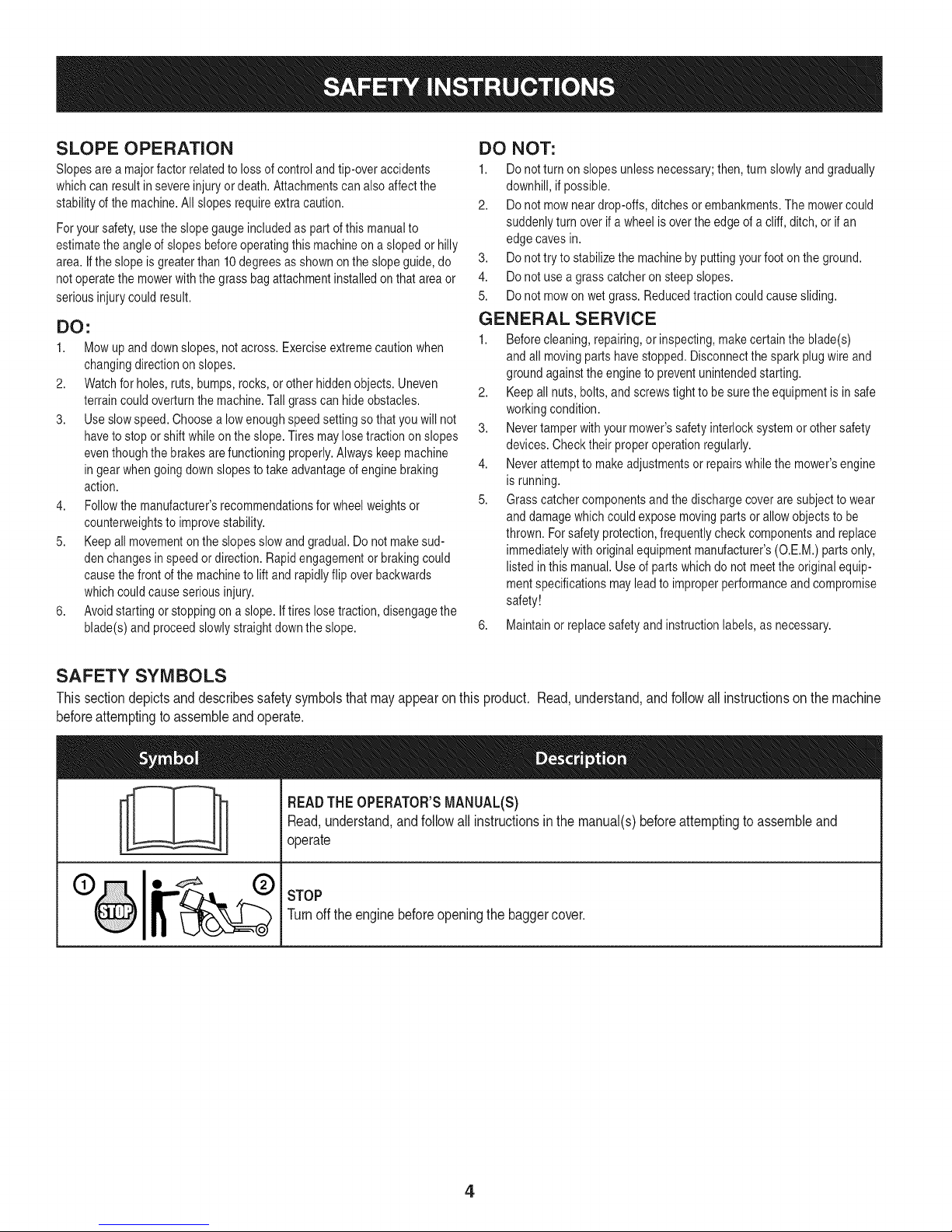
This section depicts and describes safety symbols that may appear on this product. Read, understand, and follow allinstructions on the machine
before attempting to assemble and operate.
READTHEOPERATOR'SMANUAL(S)
I
I
Read,understand,andfollowall instructionsinthe manual(s)beforeattemptingto assembleand
operate
STOP
Turnoffthe enginebeforeopeningthe baggercover.
4
Page 5
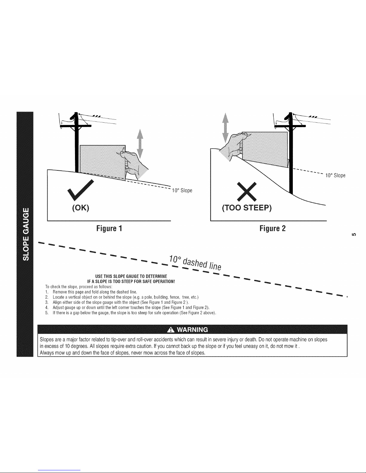
(OK)
10° Slope
(TOO STEEP)
10° Slope
Figure1
USETHiSSLOPEGAUGETODETERMINE
iFASLOPEiS TOOSTEEPFORSAFEOPERATION!
Tochecktheslope,proceedasfollows:
1. Removethis pageandfold alongthedashedline.
2. Locateavertical objectonor behindtheslope(e.g.apole,building,fence, tree,etc.)
3. Aligneither sideof theslopegaugewiththe object(SeeFigure1andFigure2).
4. Adjustgaugeup or downuntil the left cornertouchesthe slope(SeeFigure1andFigure2).
5.
10odashedline
If there isa gapbelowthe gauge,theslope is too steepfor safeoperation(SeeFigure2above).
Figure2
Slopes area majorfactor related totip-over androll-over accidentswhich canresult in severe injury or death. Donot operate machineon slopes
in excessof 10degrees. Allslopes requireextra caution,if youcannot back up the slopeor if youfeel uneasyon it, do notmow it.
Always mowup and down the face of slopes, nevermow acrosstheface of slopes.
Page 6
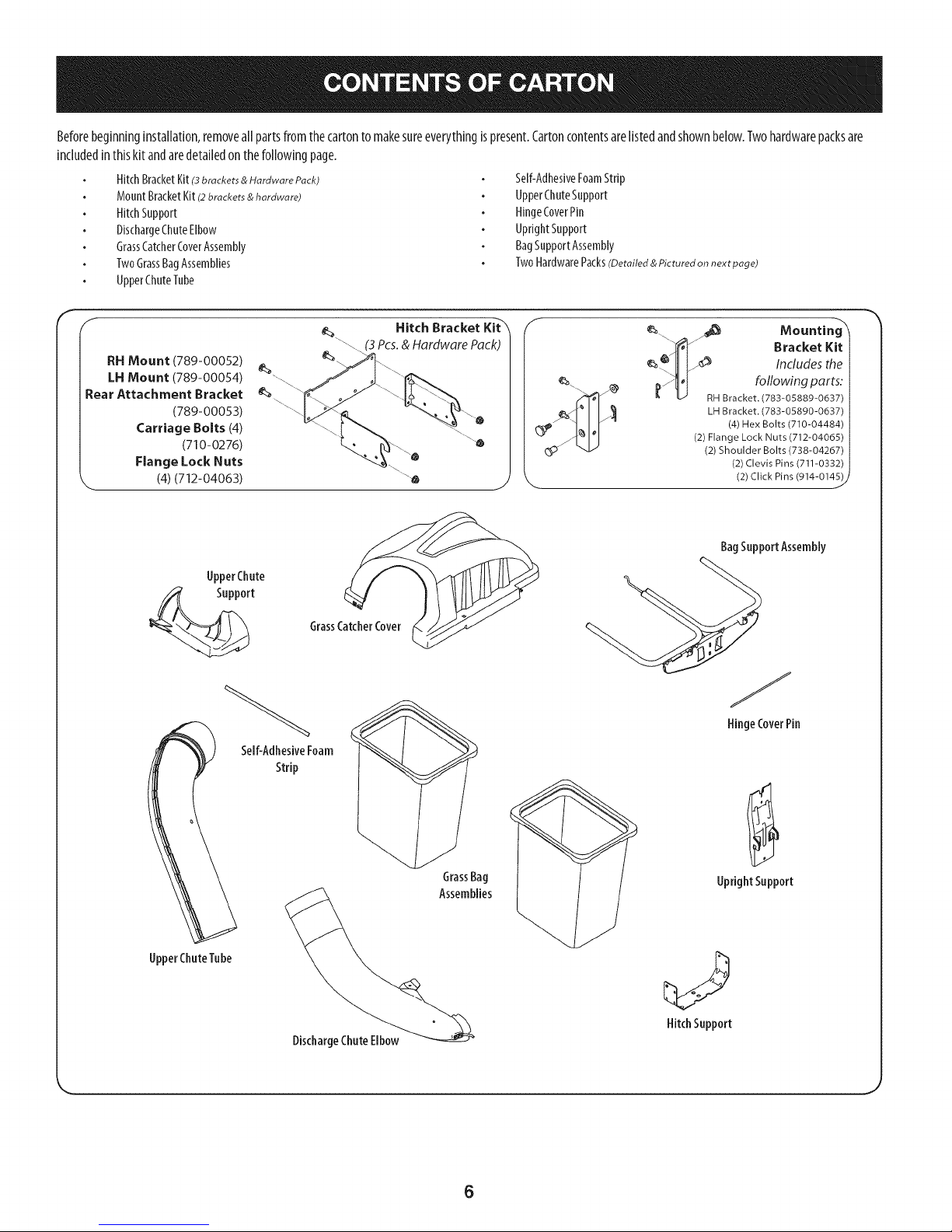
Beforebeginninginstallation,removeallpartsfromthecartontomakesureeverythingispresent.Cartoncontentsarelistedandshownbelow.Twohardwarepacksare
includedinthiskit andaredetailedonthefollowingpage.
HitchBracketKit(3brackets & Hardware Pack)
MountBracketKit(2brackets & hardware)
HitchSupport
DischargeChuteElbow
GrassCatcherCoverAssembly
TwoGrassBagAssemblies
UpperChuteTube
Self-AdhesiveFoamStrip
UpperChuteSupport
HingeCoverPin
UprightSupport
BagSupportAssembly
TwoHardwarePacks(Detailed & Pictured on next page)
F
RH Mount (789-00052)
LH Mount (789-00054)
Rear Attachment Bracket
(789-00053)
Carriage Bolts (4)
(710-0276)
Flange Lock Nuts
'-- (4) (712-04063)
UpperChute
Support
Self-AdhesiveFoam
Strip
(3 Pcs. & Hardware Pack)
GrassCatcherCover
Hitch Bracket Kit-'_'
Mountin
Bracket Kit
e_.ljl _ Includes the
LH Bracket. (783-05890-0637)
(4) Hex Bolts (710-04484)
(2) Flange Lock Nuts (712-04065)
(2) Shoulder Bolts (738-04267)
(2) Clevis Pins (711-0332)
(2) Click Pins (914-0145) j
BagSupportAssembly
@
HingeCoverPin
UpperChuteTube
DischargeChuteElbow
UprightSupport
HitchSupport
6
Page 7
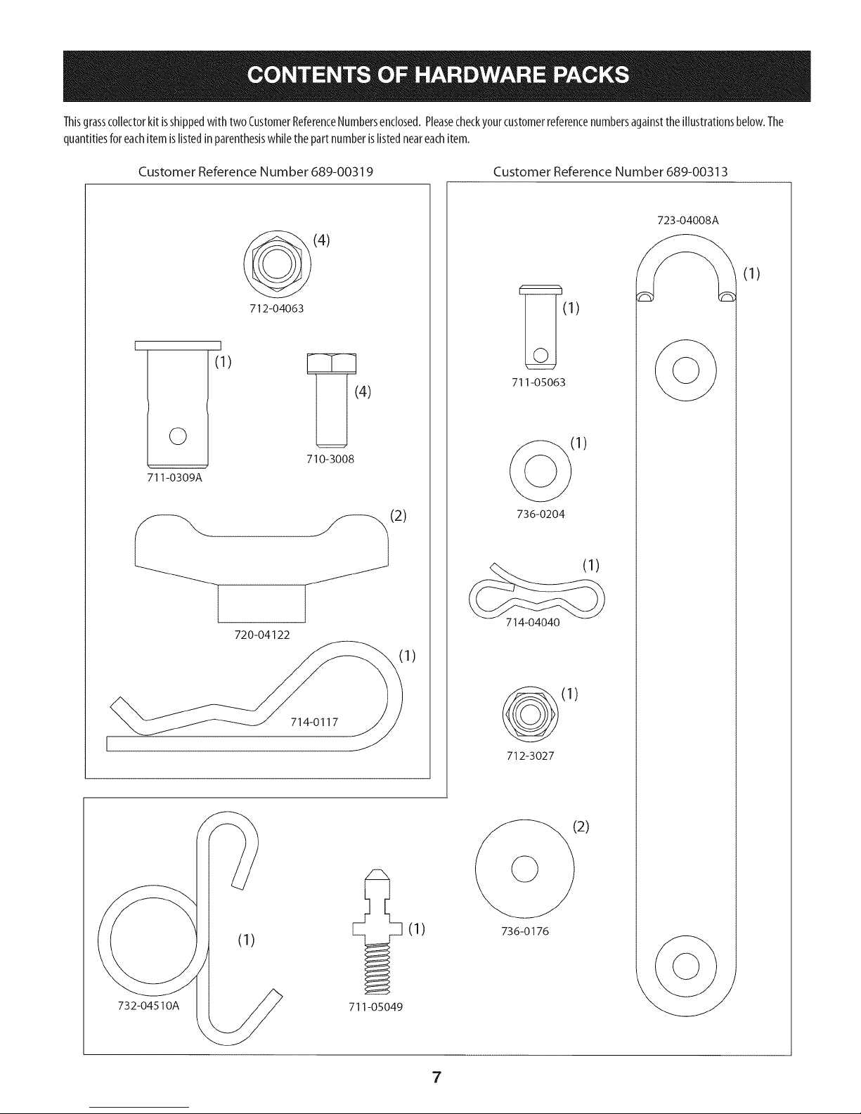
Thisgrasscollectorkitisshippedwithtwo CustomerReferenceNumbersenclosed.Pleasecheckyourcustomerreferencenumbersagainsttheillustrationsbelow.The
quantitiesforeachitemislistedinparenthesiswhilethepartnumberislistedneareachitem.
Customer Reference Number 689-00319 Customer Reference Number 689-00313
723-04008A
©
711-0309A
t
(1)
720-04122
712-04063
(4)
710-3008
4)
(2)
(1)
(1)
711-05063
(1)
736-0204
(1)
714-04040
1)
732-04510A
714-0117
711-05049
(1)
(1)
712-3027
2)
736-0176
7
Page 8

Assemblingthe MountingHardware
1. Ifnotalreadyinstalledbythefactory,installashoulderboltfromyour
hardwarepackontoeachbracket,securingthemwith flangelocknutsalso
includedinthehardwarepackincludedwiththesebrackets.RefertoFigure1.
2. Ifalreadyinstalledinthebrackets,removetheclevispinsandclips,retainfor
laterinstuctions.Referto Figure1.
AssembleMounting 8rackets
Toassemblethebaggermountingassembly,locatethehitchbracketkitandfollow
thesesteps:
I. Attachtheright-handandlefthandriderhitchbracketto theuniversalrear
attachmentbracketusingthefourcarriagebolts(710-0276)andflangelock
nuts(712-04063)packedwith themountingbrackets.Positionthebrackets
with thehooksontheright-handandleft handriderhitchbracketpointing
downward,andthetabsontheuniversalrearattachmentbracketpointing
upwards.SeeFigure3.
UniversalRear
Bracket
Hitch Side
Bracket
Figure1
3. Mountthebracketsto yourtractorusingfourself-tappinghexscrews
includedwith yourkit. SeeFigure2.
f
Figure2
Figure3
8
Page 9
Note:Thisuniversalmountingbracketassemblyisdesignedtoworkwith
otheravailableattachments,suchasaweightkit usedinconjunctionwith
thesnowbladeorsnowthrowerattachment.Utilizethecontactinformation
onthefrontorbackcoverofthismanual,orcontactthestoreinwhichyou
purchasedthisequipmenttofindoutmoreaboutavailableattachmentsfor
yourspecifictractor.
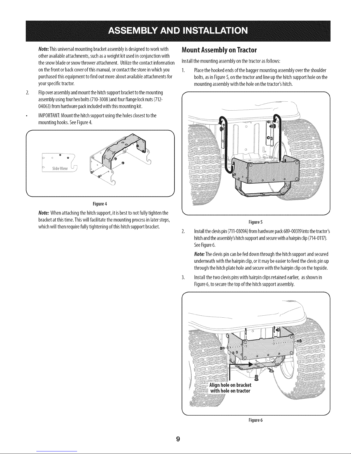
2.
Flipoverassemblyandmountthehitchsupportbrackettothemounting
assemblyusingfourhexbolts(710-3008)andfourflangelocknuts(712-
04063)fromhardwarepackincludedwiththismountingkit.
IMPORTANT:Mountthehitchsupportusingthe holesclosesttothe
mountinghooks.SeeFigure4.
f
MountAssemblyonTractor
Installthemountingassemblyonthetractorasfollows:
1. Placethehookedendsofthe baggermountingassemblyovertheshoulder
bolts,asinFigure5,onthetractorandlineupthehitchsupportholeonthe
mountingassemblywith theholeonthetractor'shitch.
o o /
............... #
....}
Figure4
Note: Whenattachingthehitchsupport,itisbesttonotfullytightenthe
bracketatthistime.Thiswill fadlitatethemountingprocessinlatersteps,
whichwillthenrequirefullytighteningofthishitchsupportbracket.
Figure5
Installtheclevispin(711-0309A)fromhardwarepack689-00319intothetractor's
hitchandtheassembly'shitchsupportandsecurewithahairpinclip(714-0117).
SeeFigure6.
Note:Theclevispincanbefeddownthroughthehitchsupportandsecured
underneathwith thehairpinclip,orit maybeeasiertofeedtheclevispinup
throughthehitchplateholeandsecurewith thehairpincliponthetopside.
Installthetwo clevispinswith hairpinclipsretainedearlier,asshownin
Figure6, tosecurethetopof thehitchsupportassembly.
J
Figure6
9
Page 10
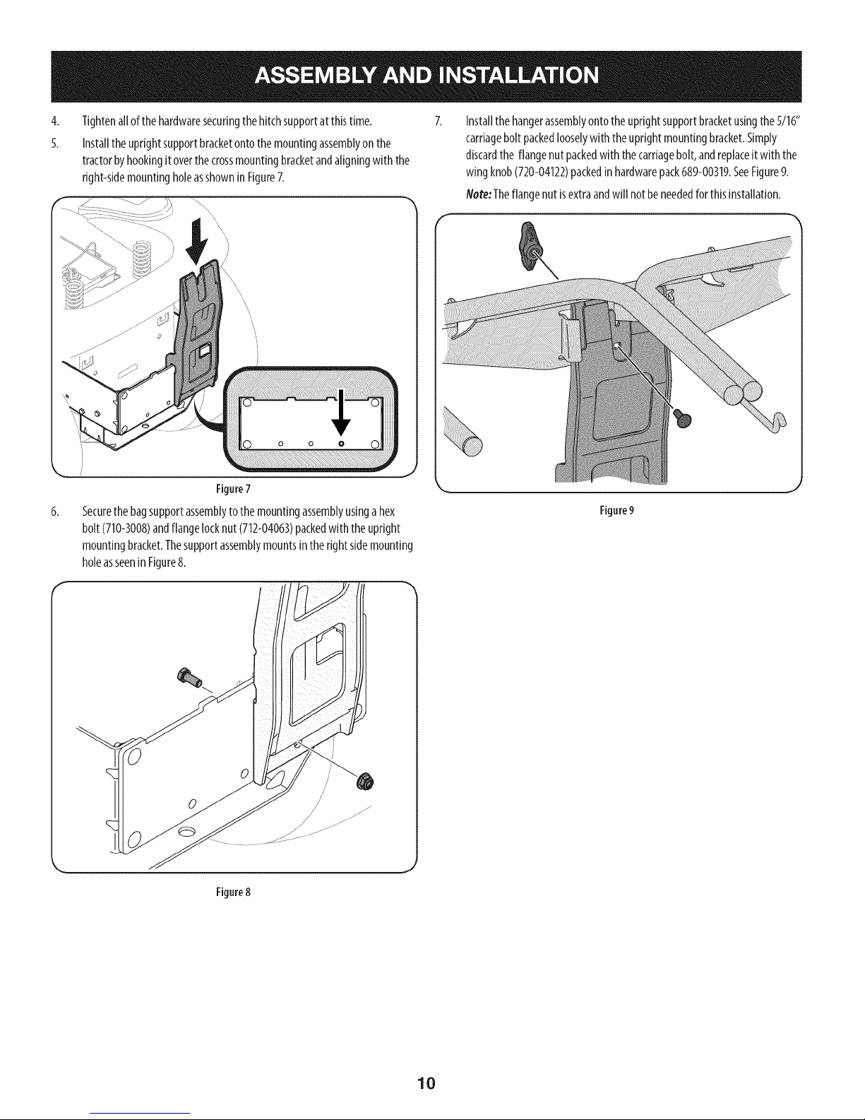
4,
Tightenallofthehardwaresecuringthehitchsupportatthistime.
5.
Installthe uprightsupportbracketontothemountingassemblyonthe
tractorbyhookingitoverthecrossmountingbracketandaligningwiththe
right-sidemountingholeasshowninFigure7.
Figure7
6,
Securethebagsupportassemblytothe mountingassemblyusingahex
bolt(710-3008)andflangelocknut(712-04063)packedwith theupright
mountingbracket.Thesupportassemblymountsintherightsidemounting
holeasseenin Figure8.
Installthehangerassemblyontotheuprightsupportbracketusingthe5/16"
carriageboltpackedlooselywith theuprightmountingbracket.Simply
discardthe flangenutpackedwith thecarriagebolt,andreplaceitwiththe
wingknob(720-04122)packedinhardwarepack689-00319.SeeFigure9.
Note:Theflangenut isextraandwillnotbeneededforthisinstallation.
Figure9
Figure8
10
Page 11

AssemblingRemainingBaggerComponents
Nowthat themountingbracketsareassembledandareinplaceonthetractor,
followthesestepstoassembletheremainingbaggercomponents.
1. Snaptheplasticupperchutesupportin placebyfirstclippingtheside
portionontothe bagsupportrailwith theedgeofthesnapfeaturealigned
with theredline(1),asshowninthe insetofFigure10.
2. Snapthefrontportionoftheupperchutesupporttothebagsupportrailas
seenin2of Figure10.
Slidethehingepinintothe holelocatedonthe mountingtab,asinFigure
12.Usethecut-outwindow(SeeinsetinFigure12)tolineupthehingepin
ontheothersideandpushpinallthewayinuntilit reachestheend-stop.At
thispointthepinclipsintoplaceandissecuredbyatabinthe baggercover.
SeeFigure13.
Figure12
Figure10
3.
Installthegrasscatchercoverontothebagsupportassembly,asseenin
Figure11.Thegrasscatchercovergoesinsideof thetwo mountingtabson
the bagsupportassembly.
f
Figure11
Figure13
11
Page 12

5.
OpenHoodbypushinginontherear,right-sidetabwith yourrighthand,as
seenin1of Figure14,andliftingthecoverwith yourlefthandinthecenterrear
ofthebaggercover,2.
Figure14
6.
Installbothgrassbagsontothebagsupportassemblybyinsertingthefront
edgeinfirst (1),asseeninFigure15,andsettingthebackedgedown(2)
untilit fitsintotheassembly.
Installingthe DeckChute
Note:Determineif yourdeckisanewermodel,oranoldermodel.Referto
the upperinsetof Figure17.Ifyourdeckhasamountingstudpresent,then
youhavea newerdeckmodelandyouwouldfollowtheinstructionsbelow.
Ifnostudispresent,referto theinstructionstitledOnTractorsWith Older
DeckConfigurations laterinthissection.
Withthetractor'sdischargechuteraisedupandheldopen(1),installthe
chuteelbowbyplatingthechuteelbowmountingrodintotheholeprovided
ineitheryourdeckwheelbracketorchutemountingtab (2),asseenin
Figure16.
Figure15
Figure16
Securethechuteelbowtothedeckusingthewing knob720-04122from
hardwarepack689-00319.SeeFigure17.
Note:Ifpresent,removetheprotectivecapoffof themountingstudonthe
mowingdeckasseenintheupperinsetofFigure17.
Figure17
12
Page 13

OnTractorswith OlderOeckConfigurations:
1. Installtherubberchutestrap,fromhardwarepack689-00313,ontothe
chuteelbowusingtheclevispin(711-05063),washer(736-0204)andBow-tie
cotterpin(714-04040)fromhardwarepack689-00313.SeeFigure18.Securethe
endofthestraputilizingtheholefurthestfromtheend,insertthetorsionspring
hook(732-04510A)intotheotherend.
Note:Ondeckswithfrontdeckwheels,thebootmountrodmustberemovedin
ordertoinstallthisdischargechuteelbowontothetractor.SeeFigure18.
I
Figure20
Note: Ondeckswithout deckwheels,hooktheretainerstrapintothehole
providedintheflangeonthefront-sideofthecuttingdeck.SeeFigure21.
\
_ Remove the Boot Mounting Rod
Figure18
2.
Installthedeckmountingpin(711-05049)upintothechuteelbowusingtwo
flatwashers(736-0176)fromhardwarepack689-00313andsecurewithaflange
locknut(712-3027),asseeninFigure18.
3.
Withthetractor'sdischargechuteraisedupandheldopen,installthechute
elbowoverthechuteopeningbyplacingthedeckmountingpininthehole
provided,asseeninFigure19,thensecuretheelbowtothedeckbyhooking
theretainerstraptorsionspringhookoverthedeckwheelmountingbracket
aseenin Figure20.
\
Figure21
Note:Whenassemblingthisbaggingunitonanolderdeck,anextrawing
knob,whichisonlyneededoninstallationsonnewdecks,will be leftover.
Figure19
13
Page 14

Installingthe UpperChuteTube
Peelthe backingoff oftheself-adhesivefoamstrip(721-04388)thathas
beenincludedwithin yourCartonofContents.Applyit totheupperchute,
flushagainsttheflangeasshownin Figure22.
Figure22
Withthegrasscatchercoveropen,installtheupperdischargechutethrough
thedischargechuteopening,asseeninFigure23.
Withtheabilitynowtowigglethedischargechutetubebackandforth,slide
itoverthechuteelbowmountedonthecuttingdeck,asshowninFigure24.
Figure24
Continuetoworkthedischargechutedownoverthechuteelbowuntilthe
grooveonthedischargechutealignswith theupperchutesupport,asseen
intheinsetof Figure25.
Figure23
Figure25
14
Page 15

BaggerOperation
NOTE:Whenbothgrassbagsarefull, placethetractoronafirm,levelsurface,
disengagethe PTO(BladeEngage),turnthetractorengineoffandsetthe parking
brake.
1,
Fliptheseatup.
2.
Opengrasscatchercoverbypushingin ontherear,right-sidetabwith your
right-hand,asseenin 1ofFigure27,andlifting withyourleft-handinthe
rearcenter,2.
Removethegrassbagsbyliftingthemup(1inFigure28)andawayfromthe
bagsupportassembly(2).
Figure28
4. Emptythegrassclippingsataproperdisposalsite.Graspthehandleatthe
bottomofthebagwithonehand,andwiththeotherhandsteadythebag,
andemptythecontents.
5. Replacegrassbags,closelid,flip downseat,restartyourtractorandresume
cuttingyourgrass.
Figure27
15
Page 16

LT_eriesMountKit i
34\ _1 I_
2O
_27
23
29
J
12
10
16
Page 17

CRAFTSMANTWOBINBAGGERModelNo.247.240192
Topurchasereplacementparts, call 1-800-469-4663
I
Ref, I Part Number
1. 689-00101
2. 710-3008
3. 711-0309A
4. 711-05049
5. 711-05063
6. 712-04063
7. 712-3027
8. 714-0117
9. 714-04040
I0. 723-04008A
II. 631-05029
12. 720-04122
13. 732-04510A
14. 736-0176
15. 736-0204
16. N/A*
17. N/A*
18. 783-05887-0637
19. 931-04295A
20. 931-04292
21. 731-06497
22. 731-06504
23. 710-0276
24. 964-04090A
25. 683-04461-0637
26. 683-04519-0637
27. 711-04988
28. 735-0246A
29. 721-04388
30. 710-04484
31. 711-0332
32. 712-04065
33. 914-0145
34. 738-04267
35 783-05889A-0637
36. 783-05890A-0637
Description
Mounting Bracket Kit (Incl. ref. 16, 17,18)
Hex HeadScrew,5/16-18 x .75"
Clevis Pin, .62" Dia.
Attachment Pin, 1/4x 0.66 Lg.
Clevis Pin, 5/16 x.75 Lg.
Flange Lock Nut, 5/16-18
Flange Lock Nut, 1/4-20
Internal Cotter Pin,.148x 3.00
Bow-Tie Cotter Pin,72
Chute Strap,6.00 Lg.
Bagger Discharge Chute, Elbow
Wing Knob, 5/16-18
Torsion Spring Hook
FlatWasher, .265 x .938 x .120
FlatWasher, .344 x .62 x .033
Mounting Bracket, LH
Mounting Bracket, RH
Universal Bracket Support
Upper Discharge Chute
Double Bagger Cover Assembly
Upper Chute Support
Bagger Cover Screen
Carriage Screw,5/16-18 x 1.00"
Grass-bagAssembly
Double Bag Support Assembly
Vertical Support Bracket
Cover Hinge Pin
End Plug
Self-Adhesive Foam Strip
Tap Screw, 5/16-18 x .750
Clevis Pin
Flange Lock Nut, 3/8-16
Click Pin,.092 x 1.64 Lg.
Shoulder Screw, .625x .412
Mounting Bracket, RH
Mounting Bracket, LH
*Order Reference 1
17
Page 18

Sinstrucciones De Seguridad ............................................... 19-21
Contenido de la Caja ............................................................. 22-23
Montaje e Instalaci6n ........................................................... 24-30
Operaci6n ................................................................................... 31
Lista de piezas ...................................................................... 16-17
GARANTiACOMPLETADE UNANODEARTESANO
DURANTEunaSodesdelafechadecompra,esteproductoestAgarantizadocontracualquierdefectode materialo manode obra.Unproducto
defectuososer_reemplazadosincargo.
Paraquedetallesde lacoberturadegarantiaobtenerunreemplazolibre,visiteel sitioweb:www.craftsman.com
EstagarantiaserAnulasiesteproductose utilizamientrasqueproporcionaservicioscomercialeso Sialquilaa otra persona.
Estagarantiale otorgaderechoslegalesespecificos,y ustedtambi_npuedetenerotrosderechosquevariandeestadoa estado.
Sears BrandsManagementCorporation., Hoffman Estates, IL 60179
© SEARSBRANDS,LLC 18
Page 19

Lapresenciadeeste sirnboloindicaque setratade instrucciones
irnportantesde seguridadquese debenrespetarparaevitar
ponerenpeligrosuseguridadpersonaly/omaterialy lade otras
personas.Leay sigatodaslasinstruccionesdeestemanualantes
de poneren funcionarnientoestarnAquina.Si no respetaestas
instruccionespodriaprovocarlesionespersonales.Cuandoveaeste
sirnbolo,ipresteatenci6na la advertencia!
EstarnAquinarueconstruidaparaseroperadadeacuerdocon
lasreglasde seguridadcontenidasenestemanual.AIigualque
concualquiertipodeequipornotorizado,undescuidoo errorpor
partedeloperadorpuedeproducirlesionesgraves.EstarnAquina
escapazde arnputarrnanosy piesy dearrojarobjetoscongran
fuerza.Deno respetarlasinstruccionesde seguridadsiguientesse
puedenproducirlesionesgraveso larnuerte.
PROPOSICION 65 DE CALIFORNIA
Elescapedel motordeesteproducto,algunosdesuscornponentes
y algunoscornponentesdelvehiculocontieneno liberansustancias
quirnicasqueelestadodeCaliforniaconsideraque puedenproducir
cancer,defectosdenacirnientouotrosproblernasreproductivos.
Losbornesdela bateriay losaccesoriosalinescontienenplornoy
cornpuestosde plorno,sustanciasquirnicasque seg_nIoestableci-
do porel Estadode Californiacausancancery daSosenel sisterna
reproductivo.Ldveselasmanos despu_sde estaren contacto
con estoscomponentes.
Fundonamiento general
1. Lea, comprenda y respete todas las instrucciones que figuran
en el equipo yen los manuales antes de intentar armarlo y
hacerlo funcionar. Guarde este manual en un lugar seguro
para consultas futuras y peri6dicas, asi como para solicitar
repuestos.
2. Para ayudar a evitar una lesi6n pot contacto con las cuchillas
o con un objeto que sea arrojado, mantenga a las personas
que observan, a los ayudantes, ni_os y mascotas alejados a no
menos de 25 metros de la m_quina mientras est& funcionando.
Detenga la m&quina si alguien entra en la zona.
3. Revise minuciosamente el _irea donde se va a usar el equipo.
Retire todas las piedras, palos, cables, huesos, juguetes y otros
objetos extra_os que podrian set recogidos y arrojados por la
acci6n de las cuchillas. Los objetos arrojados por la m&quina
pueden causar lesiones graves.
4. Para protegerse los ojos, utilice siempre galas o lentes de
seguridad mientras opera la m&quina o mientras la ajusta
o repara. Los objetos arrojados que rebotan pueden causar
lesiones oculares graves.
5. Nunca opere la cortadora de c_sped sin tenet bien colocada
la cubierta de descarga o el colector de c6sped. Si falta o
est_ da_ada la cubierta de descarga oun componente del
accesorio embolsador puede resultar en lesiones por contacto
con la cuchilla o con objetos arrojados.
6. No ponga las manos ni los pies cerca de las piezas rotatorias ni
debajo de la plataforma de corte. El contacto con las cuchillas
puede resultar en la amputaci6n de una mano o pie.
7. Apague el motor de la cortadora de c_sped y espere que
las cuchillas se detengan totalmente antes de desbloquear
la abertura de descarga de la cortadora o las piezas de la
embolsadora.
Su responsabilidad--Restrinja el usode estarnAquina
rnotorizadaalas personasquelean,cornprendany respetenlas
advertenciase instruccionesqueaparecenenestemanualyen la
rnAquina.
iGUARDEESTASINSTRUCCIONES!
8. Reduzca la velocidad antes de girar. Opere la m&quina de
forma pareja. Evite el funcionamiento err_itico y la velocidad
excesiva. Tenga en cuenta que el accesorio colector de c6sped
puede afectar las caracteristicas de manejo de su cortadora.
Fundonamiente en pendientes
Las pendientes son un factor importante en los accidentes
ocasionados pot p_rdida de control y vuelcos que pueden causar
lesiones graves e incluso la muerte. Los accesorios tambien pueden
afectar la estabilidad de la m&quina. La operaci6n en pendiente
requiere mayor precauci6n.
Para seguridad, use el medidor de pendientes que se incluye como
parte de este manual para estimar el _ingulo de la pendiente antes
de hacer funcionar la m_iquina en una zona inclinada. Si la pendiente
es mayor a 10 grados en el medidor, no opere la cortadora con el
accesorio embolsador en ese sector, pues podria causar lesiones
graves.
HagaIo siguiente:
1. Corte hacia arriba y abajo de las pendientes, no en forma
transversal. Tenga sumo cuidado al cambiar de direcci6n en
una pendiente.
2. Est_ atento a los hoyos, surcos, baches, rocas, u otros objetos
ocultos. El terreno desnivelado puede voltear la m&quina. El
pasto alto puede ocultar obst_iculos.
3. Conduzca a baja velocidad. Elija una velocidad Io
suficientemente baja como para no tener que detenerse
o cambiar de marcha mientras est,1 en la pendiente. Los
neum_ticos pueden perder tracci6n en las pendientes aun
cuando los frenos funcionen correctamente. Mantenga
la m&quina siempre en velocidad cuando desciende una
pendiente, para poder frenar con el motor.
19
Page 20

4. Siga las recomendaciones del fabricante sobre pesos y
contrapesos de las ruedas, para mejorar la estabilidad.
5. Haga que todos los movimientos en las pendientes sean
lentos y graduales. No cambie repentinamente lavelocidad
ni la direcci6n. Un frenado o cambio de velocidad repentinos
pueden causar que el frente de la m_quina se levante y d6 una
voltereta hacia atr_s, Io que podria causar lesiones graves.
6. Evite arrancar o detenerse en una pendiente. Silos neum_ticos
pierden tracci6n, desenganche las cuchillas y descienda
lentamente la pendiente.
Nohaga I0siguiente:
I. No gire en una pendiente a menos que sea imprescindible. De
ser posible, gire lenta y gradualmente cuesta abajo.
2. No corte el c_sped cerca de barrancos, zanjas o terraplenes. La
cortadora de c_sped podria volcarse repentinamente si una de
las ruedas estuviera sobre el borde de un acantilado o zanja, o
si un borde se desmoronara.
3. No intente estabilizar la m_quina poniendo el pie en el suelo.
4. No utilice un colector de c_sped en pendientes empinadas.
5. No corte el c_sped humedo. Una reducci6n en tracci6n puede
causar derrapes.
Servid0 general
I. Antes de limpiar, reparar o inspeccionar la m_quina,
compruebe que las cuchillas y todas las piezas m6viles se
hayan detenido. Desconecte el cable de la bujia y p6ngalo
haciendo masa contra el motor para evitar que arranque
accidentalmente.
2. Mantenga todas las tuercas, pernos y tornillos bien ajustados
para asegurarse de que el equipo est_ en condiciones seguras
de operaci6n.
3. Nunca intente violar el sistema de bloqueo de seguridad u
otros mecanismos de seguridad de la cortadora. Controle
peri6dicamente que funcionan correctamente.
4. No intente nunca hacer ajustes o reparaciones a la cortadora
mientras el motor est_ en marcha.
5. Los componentes del colector de c6sped y la cubierta de
descarga est_n sujetos a desgaste y daffos que podrian dejar
expuestas piezas que se mueven o permitir que se arrojen
objetos. Para proteger su seguridad, verifique frecuentemente
todos los componentes y reempl_celos inmediatamente
0nicamente con piezas de los fabricantes del equipo original
(O.E.M.) indicados en este manual. El uso de piezas que no
cumplen con las especificaciones del equipo original puede
resultar en rendimiento inadecuado y puede poner en peligro
la seguridad.
6. Mantenga o reemplace las etiquetas de seguridad y de
instrucciones seg0n sea necesario.
Simbolosde seguridad
En esta p_gina se presentan y describen los simbolos de seguridad que pueden aparecer en este producto. Lea, entienda y cumpla todas las
instrucciones incluidas en la m_quina antes de intentar armarla y utilizarla.
LEA LOS MANUALES DEL OPERADOR
Lea, entienda y cumpla todas las instrucciones incluidas en los manuales antes de intentar armar la
unidad y utilizarla.
DETENCION
Apague el motor antes de abrir la cubierta de la embolsadora.
iADVERTENCIA! Su responsabilidad--Limiteel usodeesta m_.quinamotorizadaalas personasque lean,comprendany
cumplanlasadvertenciaseinstruccionesqueaparecenenestemanualyen lam_.quina.
iGLIARDEESTASINSTRL!CCIONES!
2O
Page 21

(ACEPTAR)
Figura1
"" 10° Pendiente
10° Pendiente
(DEiVIASlADO ESCARPADO)
Figura2
0oI[nea
- - " "" - _ .-...diSC°ntinua
US0DEESTEPENDIENTEDECALIBREPARADETERiVIINAR
SIUNAPENDiENTEESDEIV1ASiADOESCARPADOPARAUNAOPERACi(_NSEGURA!
Paracomprobarlapendiente,hagaIosiguiente:
1. Borrarestap_.ginay dobleaIo largodelalineadiscontinua.
2.
3.
4.
Localizarun objetoverticalsobreo detrJ.sdelapendiente(unposte,unedificio,unavalla,un _.rbol,etc.)
Alineecadaladodependientedecalibreconelobjetovertical(consultarFigura1 andFigura2 ).
Ajusteel pendientedecalibrearribao haciaabajohastalostoquesesquinaizquierdael pendiente
(consultarFigura1andFigura2).
Sihayun espaciopordebajodelapendientedecalibre,el pendienteesdemasiadoescarpaporoperaciOn
segura(consultarFigura2 above).
Las pendientesson un factor importante relacionadocon un vuelco y renovaci6ndelos accidentesque puedenprovocar lesionesgraves o la muerte.
No utilicela m_.quinaenpendientes de m_.sde 10grados.Todos pendientesrequiere mayorprecauci6n.Si no puede retrocederen la pendiente o si se
siente inseguroen ella, no la recorte. Siempre corteel cespedarriba y abajo laspendientes, nunca en toda la superficiede la cuesta.
Page 22

Antesdecomenzarlainstalad6n,retiretodaslaspiezasdelacajaparaasegurarsedequetienetodo.Elcontenidodelacajasemuestraacontinuad6n.Estekit incluyedos
paquetesdeherrajesquesedetallanenlap_iginasiguiente.
EnganchesoporteKit(3soportesypaquetedeHardware)
Kitdesoportedemontaje(2soportesyhardware)
Soportedeenganche
Cododeconductodedescarga
MontajedelacubiertadehierbaCatcher
Soportesuperiordelatolva
Sujetadordelatapadebisagra
Soportevertical
Sacodesoporte
Dospaquetes de Hardware(detalladay representadoen lap@inasiguiente)
Dosconjuntosdebolsadehierba
Tubosuperiordelatolva
Cintadeespumaautoadhesiva
f Kit de [a m_nsuia de enganche
¢_.... _4_ Conjunto de montaje_
(3 piezas y paquete de herrajes)
Montajederecho(789-00052)
Montajeizquierdo(789-00054)
Mensuladeuni6nposterior
(789-00053)
Pernosdelcaro(4)
(710-0276)
Tuercasde seguridadconbrida
X (4)(712-04063) \
A
_ *ParaModelosLT*
_,/I_ Soportederecho (783-05889-0637)
Soporte izquierdo(783-05889-0637)
(4) Pernoshexagonales(710-04484)
(2) pernos de reborde (738-04267)
(2)Tuercasde seguridad con reborde (712-04065)
(2) Pasadores de horquilla (711-0332)
(2) Trinquetes(914-014_
%
J
22
Page 23

Estekitdecolectordehierbavienecondosnt_merosdereferendadediente adjunto.Porfavorrevisesusnt_merosdereferendadeclientecontralassiguientes
Hustradones.Lascantidadesparacadaartkuloapareceentrepar_ntesismientrasqueelnumerodepiezacotizacercadecadaelemento.
Customer Reference Number 689-00319 Customer Reference Number 689-00313
723-04008A
I
711-0309A
©
I
(1)
l
712-04063
720-04122
(4)
710-3008
(1)
(1)
711-05063
4)
736-0204
(1)
714-04040
1)
(1)
732-04510A
714-0117
711-05049
(1)
(1)
712-3027
2)
736-0176
23
Page 24

EnsamblarelHardwaredemontaje
Armadodeiasm nsuias dernontaje
1. Instaleunpernoconrebordedelpaquetedeelementosenc_dam(_nsula,
ajust_ndolosconlastuercasdeseguridadconbridaquetambi(_nse
encuentranenelpaquete.ConsultelaFigure1.
2. Instaleunpasadoresdehorquilladelpaquetedeelementosenc_da
m_nsula,seguroconlastrinquetesconbridaquetambi_nseencuentranen
elpaquete.ConsultelaFigure1.
Paraarmarlaunidaddemontajedelaembolsadora,Iocaliceelkitdelam_nsulade
engancheysigaestospasos:
1. Unalasm_nsulasdeenganchedeambosladosa lam(_nsuladeuni6ntrasera
universalconlosdospernosdelcarro(710-0276)ylastuercasdeseguridad
conbrida(712-04063)empacadasconlasm_nsulasde montaje.Coloquelas
m(_nsuiasconlosganchosdelasm_nsulasdelladoderechoyladoizquierdo
delapodadoramirandohaciaabajo,ylaslengiJetasdelam_nsuladeuni6n
traserauniversalmirandohaciaarriba.VealaFigure3.
Figure1
3. Saqueydescartelosdostorniiiosdelchasisinferiorcomosemuestraenla
Figure2.
Figure2
Figure3
Nora:Estaunidaddelam_nsulade montajeuniversalest_diseffadao
parafuncionarconotrosaccesorios,comoeseljuegodecontrapesosque
seusajunto conlacuchillaparanieveoel accesorioquitanieve.Utilicela
informaci6ndecontactodelatapadeestemanual,ocomun[queseconla
tiendadondeadquiri6elequipo,paraobtenerm_sinformaci6nsobrelos
accesoriosdisponiblesparasutractorenparticular.
VolteelaAsambleaymontarelsoportedeenganchealaAsambleade
montajeusandocuatropernoshexagonales(710-3008)ycuatrotuercasde
brida(712-04063)delpaquetedehardwareinduidoenestekitdemontaje.
IMPOR@NTE:Montarelsoportedeengancheconlosagujerosm_scercanos
alosganchosdemontaje.VealaFigure4.
Nora: AIacoplarelsoportedeenganche,convienenoajustartotalmentela
m_nsuiatodav[a.Estofacilitar_elprocesodemontajem_sadelante,cuando
sedeber_ajustarafondolam_nsuladelsoportedeenganche.
o .............'
o /
/
Figure4
24
Page 25

MontajeenelTractor
Instaleel montajeeneltractorcomosigue:
I. Coloquelosextremosenganchadosdelmontajedelrecogedorsobrelos
pernosdehombro,comoenlaFigure5,eneltractoryalineeelorificiode
soportedeengancheenel montajeconelagujerodeenganchedeltractor.
F
.........................................................................................../-.......
3. Instalelosdospernosdehorquillaconclipsdehorquillaconservadosantes,
comosemuestraenlafigura6,paraasegurarlapartesuperiordelaunidad
deapoyodelenganche.
4. Aprietetodaslaspiezasquesujetanelsoportedeengancheeneste
momento.
Instaleelsoporteverticalenelensambledemontajeeneltractor
enganch_ndolasobreelsoportedemontajetransversalyalineandoconel
orificiodeladerechacomosemuestraenlaFigure7.
f s" .............................::'_ ..............
\
}
Figure5
2.
Instaleel pasadordehorquilla(711-0309A)delpaquetedetornilleria689-
00319enelenganchedeltractorydelaAsambleael apoyoyasegurandocon
unaabrazaderadehorquilla(714-0117).VealaFigure6.
Nora:Elpasadorpuedealimentadohaciaabajoatrav(gdelsoportede
engancheyfijarsepordebajoconelbrochedehorquilla,opuedeserm_s
f_cilintrodudrel pasadordehorquillaenelorifidodela placadeenganchey
asegureconel brochedehorquillaenlapartesuperior.
Figure7
Fijeelmontajede soportedebolsaa launidaddemontajeusandounperno
hexagonal(710-3008)ytuerca(712-04063)incluidaconelsoportede
montajeverticaldel reborde.Elconjuntodelsoportesemontaenelorificio
demontajelateralderechocomoseveenlaFigure8.
Figure6
Figure8
25
Page 26

Instalealensambledelasuspensibnenelsoporteverticalutilizandoel
pernodecarruajede5/16"embaladosinapretarconelsoportedemontaje
enposici6nvertical.SimplementeDesechelatuercadebridaembaladacon
elpernodecarruajeyreemplazarloconlaperilla(720-04122)induidaenel
paquetedehardware689-00319.VealaFigure9.
Nora:Latuercadebridaesadicionaly noser_necesarioparaesta
instalacibn.
Figure9
Montaje de los ¢omponentes restantes del recogedor
Instalelacubiertaderecogedordehierbaenelconjuntodesoportedela
bolsa,comoseveenlaFigure11.Lacubiertadel colectorde hierbavadentro
delasdosleng_Jetasdemontajeenelconjuntodesoportedelabolsa.
Figure11
Desliceelpasadordelabisagraenelorifido situadoenlafichademontaje,
comoenlaFigure12.Utilicelaventanadecut-out(verrecuadrodelaFigure
12)paraalinearlabisagrapasadorenlaotraclavijalateralyempujartodos
hastaquealcanceeltope.Enestepuntolosclipsenlugaryest_asegurado
porunafichaenlatapadelcontenedor.VealaFigure13.
Ahoraquelossoportesdemontajeest_nmontadosyensulugareneltractor,siga
estospasosparamontarloscomponentesrestantesdelrecogedor.
1. Ajustarel soportepl_sticocanalsuperiorensulugarenganchandolaparte
lateralenelrieldesoportedelabolsaconelbordedelacaracteristicade
ajustealineadaconlalinearoja(1),tal comosemuestraenelrecuadrodela
Figure10.
2. Coloquelapartedelanteradelsoportesuperiordelconductoalabarrade
soportede labolsacomoseveenla2delaFigure10.
Figure12
Figure10
26
Page 27

f "_ 6. Instaleambasbolsasdehierbaenelconjuntodesoportedebolsalnsertando
elbordedelanteroenprimera(1),comoseveenlaFigure15,ybajarelborde
posterior(2)hastaqueencajeenlaAsamblea.
k,, _,
Figure13
5. Abraelcap6empujandolapestaffatrasera,ladoderechoconlamanoderecha,
comoseveenla1delaFigure14,ylevantarlatapaconlamano[zqulerdaenla
parteposteriordecentrodelatapadelcontenedor,2.
Figure15
Figure14
27
Page 28

Instalaci6ndeiconductodecubierta
Conconductodedescargadeltractorlevantadoyabierta(I),instaleel
cododeconductocolocandolabarrademontajedelcododeconductoenel
orifidocorrespondienteenelsoportedelaruedadecubiertao lengiJetade
montajedelconducto(2),comoseveenlaFigure16.
Nora:Determinesisucubiertaesunmodelonuevo,ounmodeloantiguo.
ConsulteelrecuadrosuperiordelaFigure17.Sisucubiertatieneunpernode
montajepresente,tendr_unnuevomodelode cubiertayquedeberiaseguir
lassiguientesinstrucdones.Sinoposte,consultelasinstrucdonestituladas
entractoresconmayorescubiertaconfiguradonesm_sadelanteenesta
secd6n.
Enlostractoresconmayoresconfiguradonesdecubierta:
1. Instalelacorreadeconductodegoma,delpaquetedetornilleria689-00313,
enelcododeconductoutilizandoel pasadordehorquilla(711-05063),
laarandela(736-0204)ypajaritapasador(714-04040)del paquetede
tornilleria689-00313.Vealafigura18.Sujeteelextremodelacorrea
utilizandoelagujerom_salejadodelfinal,inserteelganchoderesortede
torsi6n(732-04510A)enelotroextremo.
Nora:Encubiertasconruedasfrontaldelaplataforma,lavarilladesoporte
dearranquedebeserremovidaparainstalarestecododeconductode
descargaeneltractor.Veala Figure18.
U
//
/
Figure16
Fijeelcododelconductoa lacubiertausandolaperilla720-04122del
paquetedetornilleria689-00319.VealaFigure17.
Nota:Siest_presente,retirelatapaprotectoraenelpernode fijad6nenla
plataformadecortecomoseveenel recuadrosuperiordelaFigure17.
I
Rt I II d t d
e areevaraa era?, aJe earra,que
Figure18
2. Instaleelpasadordemontajedelacubierta(711-05049)hastaenelcodo
deconductocondosarandelasplanas(736-0176)delpaquetedetornilleria
689-00313yasegtirelaconunatuercaconbrida(712-3027),comoseveen
laFigure18.
3. Conladescargadeltractorconductolevantadoyabierta,[nstaleel codo
deconductosobreel conductodeaperturamediantelacolocad6ndela
cubiertademontajepernoenel orifidocorrespondiente,comoseveenla
Figure19,entoncesseguroengancheelcodoalacubierta,enganchandoel
resortedetorsi6ndelacorreadesujed6nsobreel soportedemontajedela
ruedadecubiertaunvistoenFigure20.
Figure17 Figure19
28
Page 29

0 Instalad6ndel tubode conductosuperior
Figure20
Nora:Encubiertassinruedasdecubierta,engancharlacorreaderetenci6n
enelorificiocorrespondienteenlapestaffaenla partefrontaldela
plataformadecorte.Veala Figure21.
Desprendaelrespaidodelatiradeespumaautoadhesiva(721-04388)que
hasidoincluidadentrodesucart6ndecontenido.Aplicaa latolvasuperior,
al rascontraelrebordecomosemuestraenlaFigure22.
Figure22
Conlatapadelcolectordehierbaabierto,instaleel conductodedescarga
superiora tray,sdelconductodedescarga,abertura,comoseveenlaFigure
23.
Figure21
Nora:AImontarestaunidaddeembolsadoenunacubiertam_santigua,
sedejar_unaperillaextra,ques61oesnecesarioenlasinstalacionesen
cubiertasde nuevos.
Figure23
29
Page 30

3. Withtheabilitynowtowigglethedischargechutetubebackandforth,slide
itoverthechuteelbowmountedonthecuttingdeck,asshowninFigure24.
Figure24
4.
Continuetoworkthedischargechutedownoverthechuteelbowuntil the
grooveonthedischargechutealignswith theupperchutesupport,asseen
intheinsetofFigure25.
Figure25
30
Page 31

Fundonamiento de ia embolsadora
NOTA:Cuandolosdoscubosparac#spedest#nIlenos,coloqueeltractor
sobreunasuperfidefirmeynivelada,desenganchelatomadefuerza(PTO),
apagueel motordeltractorycoloqueelfrenodeestadonamiento.
1. Volt_eelasientohadaarriba.
Abralacubiertade c#spedempujandoenlapartetrasera,ladoderechodela
fichaconsumanoderecha,comoseveenlaFigure1.29,ydelevantarconla
manoizquierdaenelcentrodelapartetrasera,2.
Eliminarloscubosdelahierbaporlevantarlashasta(1enlaFigure2)yfuera
delaasambleadeapoyobin(2).
Figure2
Vacielosrecortesdepastoenunprediodeeliminad6nadecuado,usela
manijadelfondodecadacubodec#sped.Paravadarelcontenidosostenga
firmementeelcubo.
Vuelvaacolocarloscubos,derrelatapa,volt#eel asientohadaabajo,
arranqueeltractorycontint_ecortandoelc#sped.
Figure1
31
Page 32

This page intentionally left blank. Use this page to make any notes regarding your bagger.
32
 Loading...