

Page 1

perator's
I:RnFrSMRN°
TWO BiN BAGGER
Model No. 247.24019.1
\
• Espanol, p. 18
iMPORTANT:
Read and follow all Safety
Rules and instructions before
operating this equipment.
Sears Brands Management Corporation, Hoffman Estates, IL 60179 U.S.A.
Visit our website: www.craftsman.com FormNo.769-05633F
For answers to your questions about
this product, Call:
1-800=659=5917
CraftsmanTractorHelpLine
7 am = 7 pm CT, Mort. =Sun.
(November14,2011)
Page 2

Safe Operation Practices .............................................. 3-4
Slope Guide ....................................................................... 5
Contents of Carton & Hardware Packs .......................... 6-7
Assembly and Installation ............................................ 8-14
Operation ........................................................................ 15
Parts List .................................................................... 16-17
Espa_ol ............................................................................ 18
Service Numbers ............................................. Back Cover
Craftsman Full Warranty
IfthisCraftsmanproductfailsduetoadefectin materialor workmanshipwithinoneyearfromthe dateofpurchase,returnit toanySearsstoreor
otherCraftsmanoutletinthe UnitedStatesforfree replacement.
ThiswarrantycoversONLYdefectsin materialandworkmanship.SearswillNOTpayfor:
• Replacementofbags,whichareexpendableitemsthatcan wearoutfromnormalusewithinthewarrantyperiod.
• Repairsnecessarybecauseof accidentorfailuretooperateormaintainthe productaccordingtoall suppliedinstructions.
Thiswarrantyappliesforonly 90daysif this productis everusedfor commercialor rentalpurposes.
Thiswarrantyappliesonly whilethisproductis usedinthe UnitedStates.
Thiswarrantygivesyouspecificlegalrights,andyou mayalsohaveotherrightswhichvaryfromstatetostate.
Sears BrandsManagementCorporation., Hoffman Estates,IL 60179
© KCDIRLLC 2
Page 3
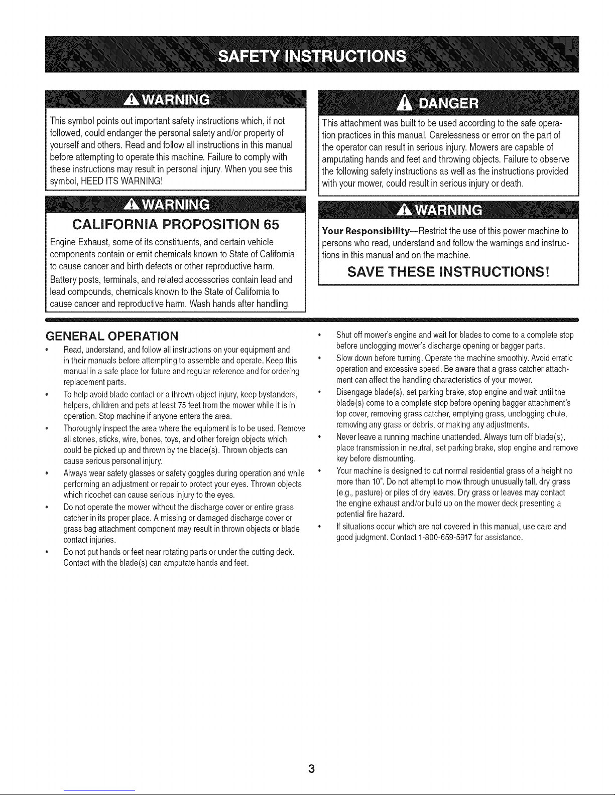
Thissymbolpointsout importantsafetyinstructionswhich,if not
followed,couldendangerthepersonalsafetyand/orpropertyof
yourselfandothers. Readandfollowallinstructionsin thismanual
beforeattemptingtooperatethismachine.Failureto complywith
theseinstructionsmayresultin personalinjury.Whenyouseethis
symbol,HEEDITSWARNING!
Thisattachmentwas builttobe usedaccordingto thesafeopera-
tionpracticesinthis manual.Carelessnessor erroronthe partof
theoperatorcanresultin seriousinjury.Mowersarecapableof
amputatinghandsandfeetandthrowingobjects.Failuretoobserve
thefollowingsafetyinstructionsas wellasthe instructionsprovided
withyourmower,could resultin seriousinjuryordeath.
CALIFORNIA PROPOSITION 65
EngineExhaust,someof itsconstituents,andcertainvehicle
componentscontainoremitchemicalsknownto StateofCalifornia
tocausecancerandbirthdefectsorotherreproductiveharm.
Batteryposts,terminals,and relatedaccessoriescontainleadand
leadcompounds,chemicalsknowntotheStateof Californiato
causecancerandreproductiveharm.Washhandsafterhandling.
GENERAL OPERATION
,, Read,understand,and followall instructionsonyourequipmentand
intheir manualsbeforeattemptingtoassembleandoperate.Keepthis
manualina safe placeforfutureand regularreferenceandfor ordering
replacementparts.
,, Tohelpavoidbladecontactora thrownobjectinjury,keepbystanders,
helpers,childrenand petsat least75feetfromthe mowerwhile itis in
operation.Stopmachineif anyoneentersthe area.
,, Thoroughlyinspectthe areawheretheequipmentisto beused.Remove
allstones,sticks,wire,bones,toys,and otherforeignobjectswhich
couldbepickedupand thrownbythe blade(s).Thrownobjectscan
causeseriouspersonalinjury.
,, Alwayswearsafetyglassesor safetygogglesduringoperationand while
performinganadjustmentorrepairto protectyoureyes.Thrownobjects
whichricochetcancauseseriousinjurytothe eyes.
,, Donotoperatethe mowerwithoutthe dischargecoveror entiregrass
catcherinits properplace.A missingor damageddischargecoveror
grassbagattachmentcomponentmayresult inthrownobjectsor blade
contactinjuries.
,, Donotputhandsorfeet nearrotatingpartsor underthecuttingdeck.
Contactwiththe blade(s)can amputatehandsandfeet.
Your Responsibility--Restrict theuseof thispowermachineto
personswhoread,understandandfollowthewarningsand instruc-
tionsin thismanualandon themachine.
SAVE THESE INSTRUCTIONS!
,, Shutoffmower'sengineandwaitfor bladesto come toa completestop
beforeuncloggingmower'sdischargeopeningor baggerparts.
,, Slowdownbeforeturning.Operatethe machinesmoothly.Avoiderratic
operationandexcessivespeed.Beawarethata grasscatcherattach-
mentcanaffectthe handlingcharacteristicsofyour mower.
,, Disengageblade(s),set parkingbrake,stopengineandwaituntilthe
blade(s)cometo acompletestop beforeopeningbaggerattachment's
top cover,removinggrasscatcher,emptyinggrass,uncloggingchute,
removingany grassordebris,or makinganyadjustments.
,, Neverleavearunningmachineunattended.Alwaysturn offblade(s),
placetransmissionin neutral,set parkingbrake,stopengineandremove
keybeforedismounting.
,, Yourmachineisdesignedtocut normalresidentialgrassof a heightno
morethan10".Do notattemptto mowthroughunusuallytall,dry grass
(e.g.,pasture)or pilesofdry leaves.Drygrassorleavesmaycontact
the engineexhaustand/or buildup onthe mowerdeckpresentinga
potentialfirehazard.
,, If situationsoccurwhichare notcoveredinthis manual,usecare and
goodjudgment.Contact1-800-659-5917for assistance.
3
Page 4
SLOPE OPERATION
Slopesare a majorfactorrelatedto lossofcontrolandtip-overaccidents
whichcan resultinsevereinjuryordeath.Attachmentscanalsoaffect the
stabilityofthe machine.All slopesrequireextracaution.
Foryoursafety,usethe slopegaugeincludedas partof thismanualto
estimatetheangle of slopesbeforeoperatingthismachineona slopedor hilly
area.Iftheslope is greaterthan 10degreesasshownonthe slopeguide,do
notoperatethemowerwiththe grassbagattachmentinstalledonthat areaor
seriousinjurycouldresult.
DO:
1. Mow upanddownslopes,not across.Exerciseextremecautionwhen
changingdirectiononslopes.
2. Watchforholes,ruts,bumps,rocks,or otherhiddenobjects. Uneven
terraincouldoverturnthe machine.Tallgrasscan hideobstacles.
3. Useslowspeed.Choosea lowenoughspeedsettingsothat youwill not
haveto stopor shift whileonthe slope.Tiresmaylosetractiononslopes
eventhoughthe brakesarefunctioningproperly.Alwayskeepmachine
in gearwhengoingdownslopesto takeadvantageofenginebraking
action.
4. Followthe manufacturer'srecommendationsfor wheelweightsor
counterweightsto improvestability.Forrecommendations,contact
1-800-659-5917.
5. Keepall movementontheslopesslowand gradual.Do notmakesud-
denchangesin speedor direction.Rapidengagementor brakingcould
causethefrontof the machineto liftand rapidlyflip overbackwards
whichcouldcauseseriousinjury.
6. Avoidstartingor stoppingon aslope.Iftires losetraction,disengagethe
blade(s)andproceedslowlystraightdownthe slope.
DO NOT:
1. Donotturnon slopesunlessnecessary;then,turnslowlyand gradually
downhill,ifpossible.
2. Do notmowneardrop-offs,ditchesor embankments.Themowercould
suddenlyturnoverif a wheelisoverthe edgeof a cliff,ditch,or if an
edgecavesin.
3. Do nottry tostabilizethe machinebyputtingyourfooton theground.
4. Do notusea grasscatcheronsteepslopes.
5. Do notmowonwet grass. Reducedtractioncouldcausesliding.
GENERAL SERVICE
1. Beforecleaning,repairing,orinspecting,makecertainthe blade(s)
andall movingparts havestopped.Disconnectthe spark plugwireand
groundagainsttheenginetopreventunintendedstarting.
2. Keep allnuts, bolts,and screwstightto besurethe equipmentisin safe
workingcondition.
3. Nevertamperwith yourmower'ssafetyinterlocksystemor othersafety
devices.Checktheirproperoperationregularly.
4. Neverattemptto makeadjustmentsorrepairswhilethemower'sengine
is running.
5. Grasscatchercomponentsandthe dischargecoverare subjectto wear
anddamagewhichcouldexpose movingpartsor allowobjectsto be
thrown.Forsafetyprotection,frequentlycheckcomponentsandreplace
immediatelywith originalequipmentmanufacturer's(O.E.M.)parts only,
listedinthis manual.Useof parts whichdo not meetthe originalequip-
mentspecificationsmayleadto improperperformanceandcompromise
safety!
6. Maintainor replacesafetyand instructionlabels,asnecessary.
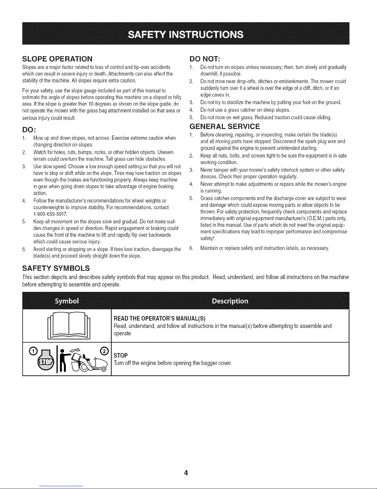
SAFETY SYMBOLS
This section depicts and describes safety symbols that may appear on this product. Read, understand, and follow allinstructions on the machine
before attempting to assemble and operate.
READTHEOPERATOR'SMANUAL(S)
I
I
Read,understand,andfollowall instructionsinthe manual(s)beforeattemptingtoassembleand
operate
STOP
Turnoffthe enginebeforeopeningthe baggercover.
4
Page 5
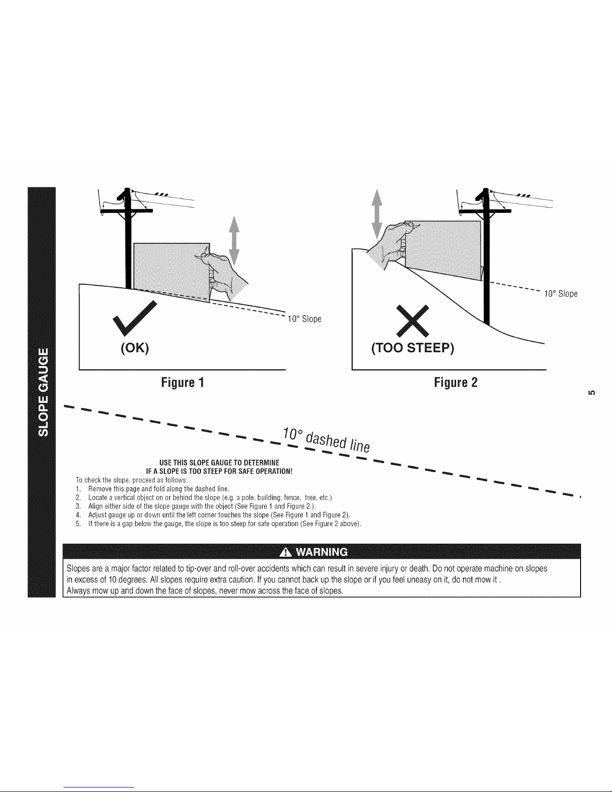
(OK)
10° Slope
(TOO STEEP)
10° Slope
Figure1
USETHiSSLOPEGAUGETODETERMINE
iFASLOPEiS TOOSTEEPFORSAFEOPERATION!
Tochecktheslope,proceedasfollows:
1. Removethis pageandfold alongthedashedline.
2. Locateavertical objectonor behindtheslope(e.g.apole,building,fence, tree,etc.)
3. Aligneither sideof theslopegaugewiththe object(SeeFigure1 andFigure2 ).
4. Adjustgaugeup or downuntil the left cornertouchesthe slope(SeeFigure1andFigure2).
5.
10odashedline
If there isa gapbelowthe gauge,theslope is too steepfor safeoperation(SeeFigure2above).
Figure2
Slopes area majorfactor related totip-over androll-over accidentswhich canresult in severe injury or death. Donot operate machineon slopes
in excessof 10degrees. Allslopes requireextra caution,if youcannot back up the slopeor if youfeel uneasyon it, do notmow it.
Always mowup and down the face of slopes, nevermow acrosstheface of slopes.
Page 6
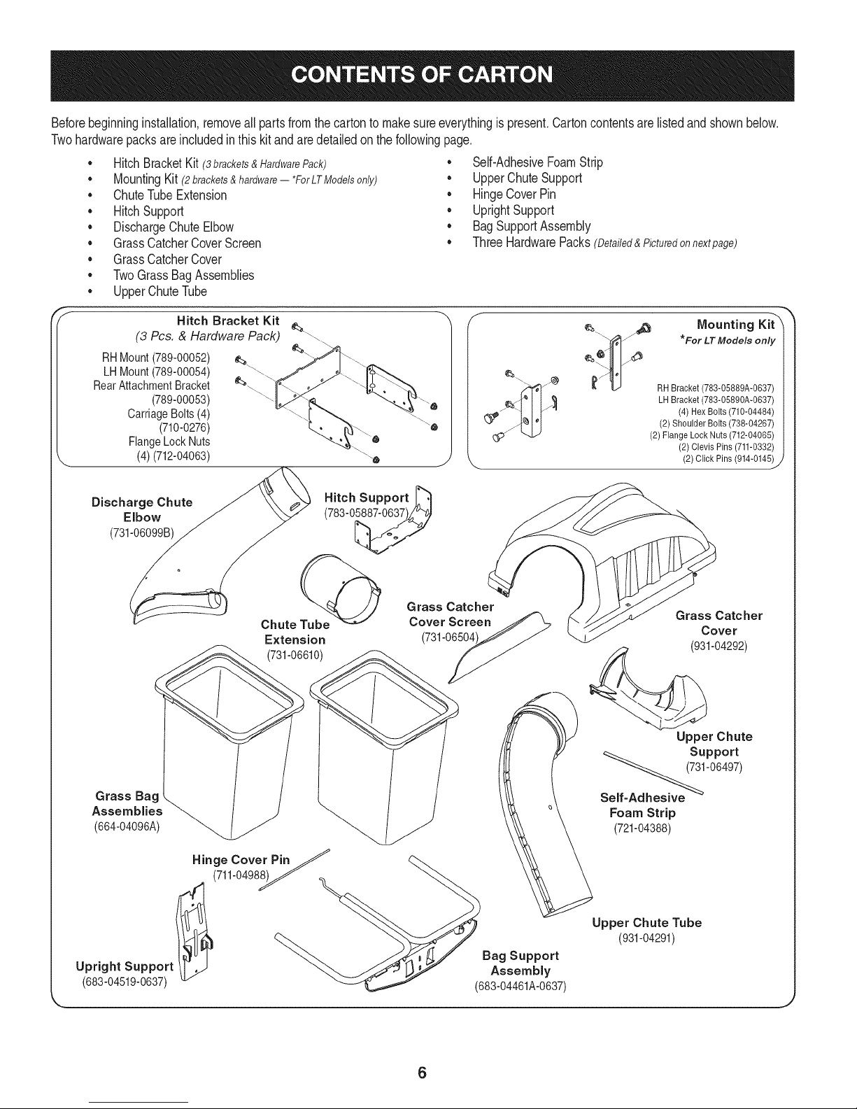
Beforebeginninginstallation,removeallpartsfromthe cartontomakesureeverythingispresent.Cartoncontentsarelistedand shownbelow.
Twohardwarepacksareincludedin thiskit andaredetailedon thefollowingpage.
• HitchBracketKit(3 brackets & Hardware Pack)
MountingKit (2brackets&hardware-- *ForLTModelsonly)
• ChuteTubeExtension
• HitchSupport
• DischargeChuteElbow
• GrassCatcherCoverScreen
• Self-AdhesiveFoamStrip
• UpperChuteSupport
• HingeCoverPin
• UprightSupport
• BagSupportAssembly
• ThreeHardwarePacks(Detailed&Picturedonnextpage)
• GrassCatcherCover
• TwoGrassBagAssemblies
• UpperChuteTube
Hitch Bracket Kit
(3 Pcs. & Hardware Pack) __.\
RHMount(789-00052)
LHMount(789-00054)
RearAttachmentBracket
(789-00053)
CarriageBolts(4)
(710-0276)
FlangeLockNuts
(4)(712-04063)
Discharge Chute
Elbow
(731-06099B)
Chute Tube@
Extension
(731-06610)
Hitch Support _"_
(783-0_
Grass Catcher
Cover Screen
(731-06504
Mounting Kit"X
*For LTModels only
RH Bracket (783-05889A-0637)
_ LH Bracket (783-05890A-0637)
(4) Hex Bolts (710-04484)
(2) ShoulderBolts (738-04267)
(2) FlangeLock Nuts (712-04065)
(2)Clevis Pins (711-0332)
(2) Click Pins (914-0145)
Grass Catcher
Cover
(931-04292)
_J
Grass Bag .
Assemblies _(664-04096A)
Hinge Cover PinJ
(711-0498__
Upright Support Assembly
(683-04519-0637) (683-04461A-0637)
Upper Chute
Support
Self_'06497)
Foam Strip
(721-04388)
Upper Chute Tube
(931-04291)
Bag Support
6
Page 7
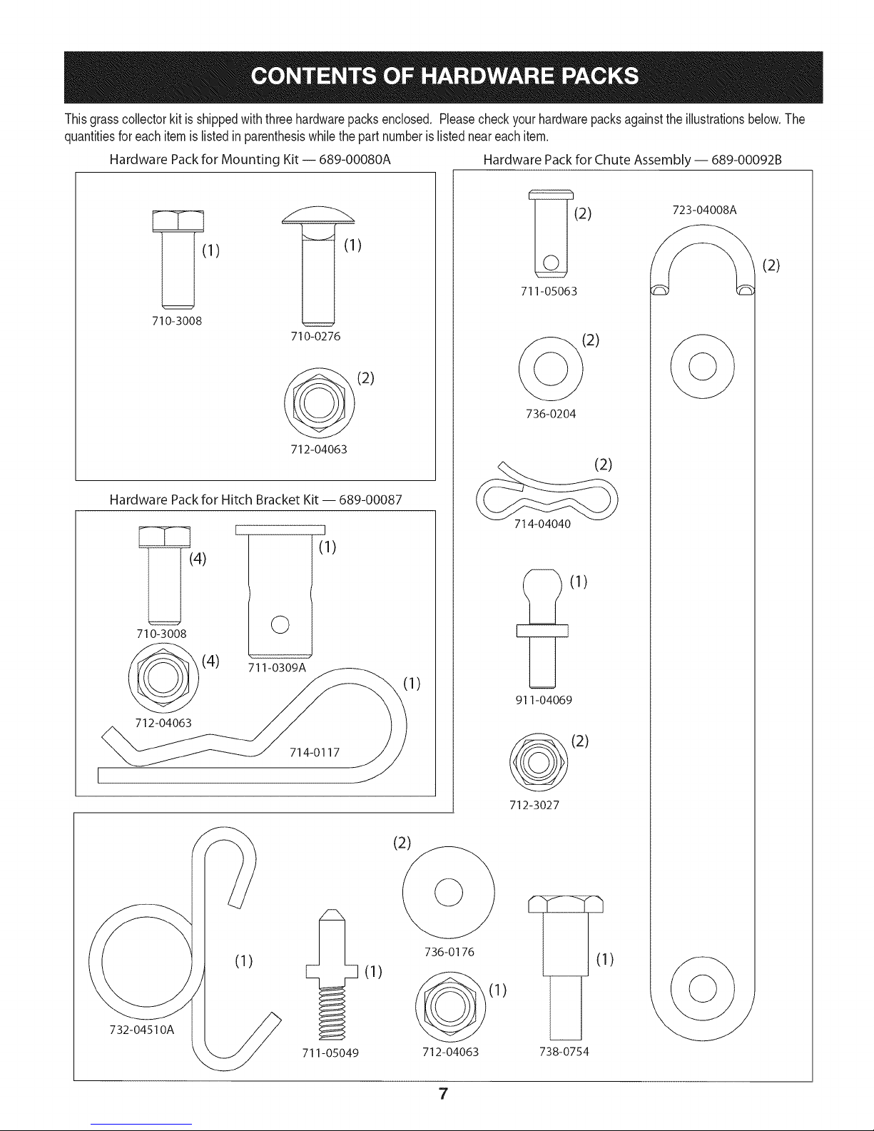
Thisgrasscollectorkitis shippedwith threehardwarepacksenclosed. Pleasecheckyourhardwarepacksagainsttheillustrationsbelow.The
quantitiesforeachitemis listedin parenthesiswhilethepartnumberislistedneareachitem.
Hardware Packfor Mounting Kit -- 689-00080A Hardware Packfor Chute Assembly-- 689-00092B
1) )
(2) 723-04008
711-05063
710-3008
710-0276
(2)
(2)
(2)
712-04063
Hardware Pack for Hitch Bracket Kit- 689-00087
I
I
(1)
4)
710-3008
(4)
712-04063
©
711-0309A
714-0117
736-0204
(2)
714-04040
E_(1)
I)
911-04069
(2)
712-3027
732-04510A
711-05049
(1)
(2)
736-0176
712-04063 738-0754
7
-h
(1)
Page 8
identify The Model of Tractor
Thismanualisdesignedforinstallationof thisnewbagginguniton
severaldifferentmodelsoftractors. Itis importantfor youto determine
whichmodeloftractorthatyou have. Oncethisis known,followthe
pertinentsetofinstructionson thefollowingpages.
Todeterminewhichmodeloftractoryouhave,lookatthe tractor's
modelplate,locatedunderthe seat. Simplyflipthe seatupand locate
themodelplate,whichwillincludethe modelnumber(e.g.Lawn
Tractor247.XXXXX)andserialnumber.
Ifyouareassemblingthis baggerunitforuse onany LTSeries lawn
tractor,you willneedtoinstallthetwo tractormountingbrackets
packedinyourbaggerkit. Ifyou areinstallingthis baggerunitonany
YTSeries yardtractor,disregardthesestepsandmoveto Assemble
MountingBrackets.
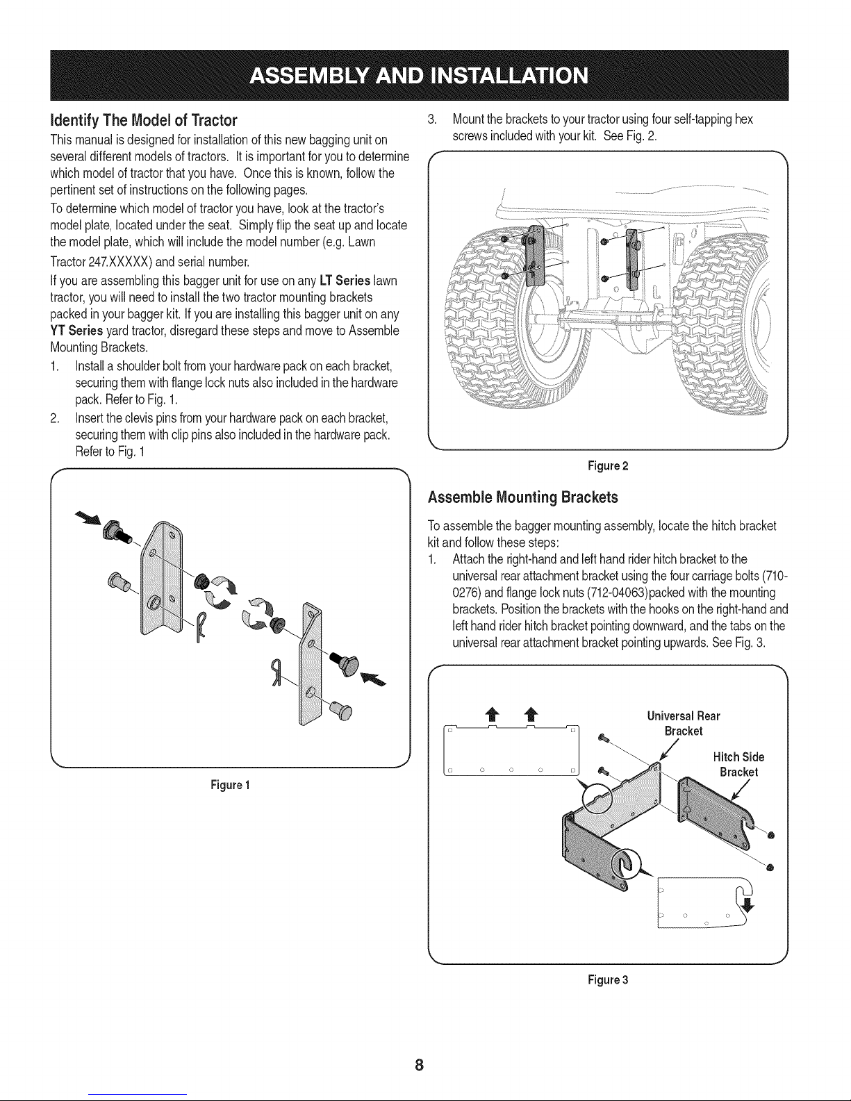
1. Installa shoulderboltfromyourhardwarepackoneachbracket,
securingthemwithflangelocknutsalsoincludedinthehardware
pack.RefertoFig.1.
2. Inserttheclevispinsfromyourhardwarepackoneachbracket,
securingthemwithclip pinsalsoincludedinthehardwarepack.
Referto Fig.1
.
Mountthe bracketstoyourtractorusingfourself-tappinghex
screwsincludedwithyourkit. SeeFig.2.
f
L.
Figure2
Assemble MountingBrackets
Figure1
Toassemblethebaggermountingassembly,locatethe hitchbracket
kit andfollowthesesteps:
1. Attachtheright-handandIdt handriderhitchbrackettothe
universalrearattachmentbracketusingthefourcarriagebolts(710-
0276)andflangelocknuts(712-04063)packedwiththemounting
brackets.Positionthebracketswiththe hooksontheright-handand
Idt handriderhitchbracketpointingdownward,andthe tabsonthe
universalrearattachmentbracketpointingupwards.SeeFig.3.
f
UniversalRear
Bracket
J
i o o
HitchSide
Bracket
Figure3
8
Page 9
Note: Thisuniversalmountingbracketassemblyisdesignedto
workwithotheravailableattachments,suchasaweightkitusedin
conjunctionwiththesnowbladeor snowthrowerattachment.Utilize
thecontactinformationonthe frontor backcoverofthis manual,or
contactthestorein whichyoupurchasedthisequipmenttofindout
moreaboutavailableattachmentsfor yourspecifictractor.
.
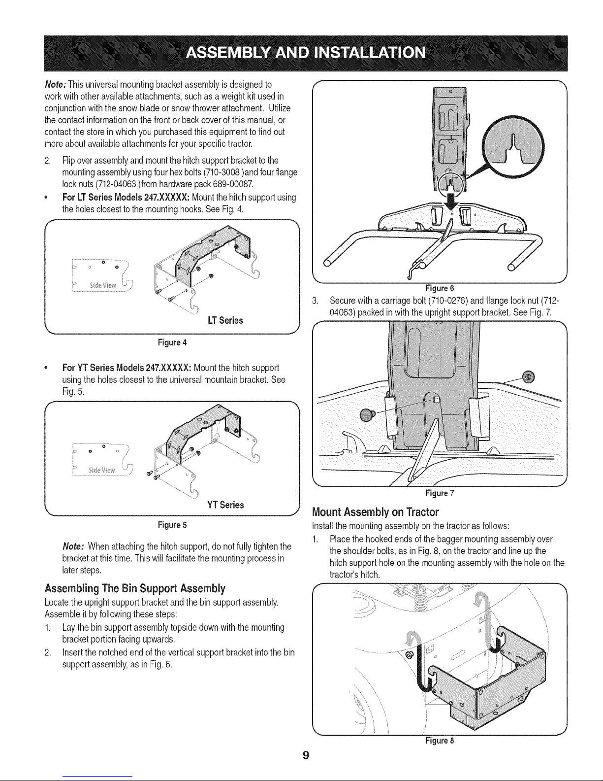
Flipoverassemblyandmountthehitchsupportbracketto the
mountingassemblyusingfourhexbolts(710-3008)andfourflange
locknuts(712-04063)fromhardwarepack689-00087.
ForLT SeriesModels247.XXXXX:Mountthehitchsupportusing
theholesclosestto themountinghooks.SeeFig.4.
_" ...... i?_;_
.................,,)
LTSeries
Figure4
ForYT SeriesModels247.XXXXX:Mountthehitchsupport
usingthe holesclosesttotheuniversalmountainbracket.See
Fig.5.
F
Figure6
Securewitha carriagebolt (710-0276)andflangelocknut(712-
04063)packedinwiththeuprightsupportbracket.SeeFig.7.
J
i...............................................................................•
YTSeries
Figure 5
Note: Whenattachingthehitchsupport,do notfullytightenthe
bracketatthistime.Thiswill facilitatethe mountingprocessin
latersteps.
AssemblingThe Bin Support Assembly
Locatetheuprightsupportbracketandthe binsupportassembly.
Assembleitbyfollowingthesesteps:
1. Laythebin supportassemblytopsidedownwiththe mounting
bracketportionfacingupwards.
2. Insertthenotchedendof the verticalsupportbracketintothebin
supportassembly,asin Fig.6.
Figure7
J
Mount Assemblyon Tractor
Installthemountingassemblyonthe tractorasfollows:
1. Placethehookedendsof thebaggermountingassemblyover
theshoulderbolts,as inFig.8, onthetractorandlineup the
hitchsupportholeon themountingassemblywiththe holeonthe
tractor'shitch.
\
\
\
\
........ ,
\
Figure8
9
J
Page 10
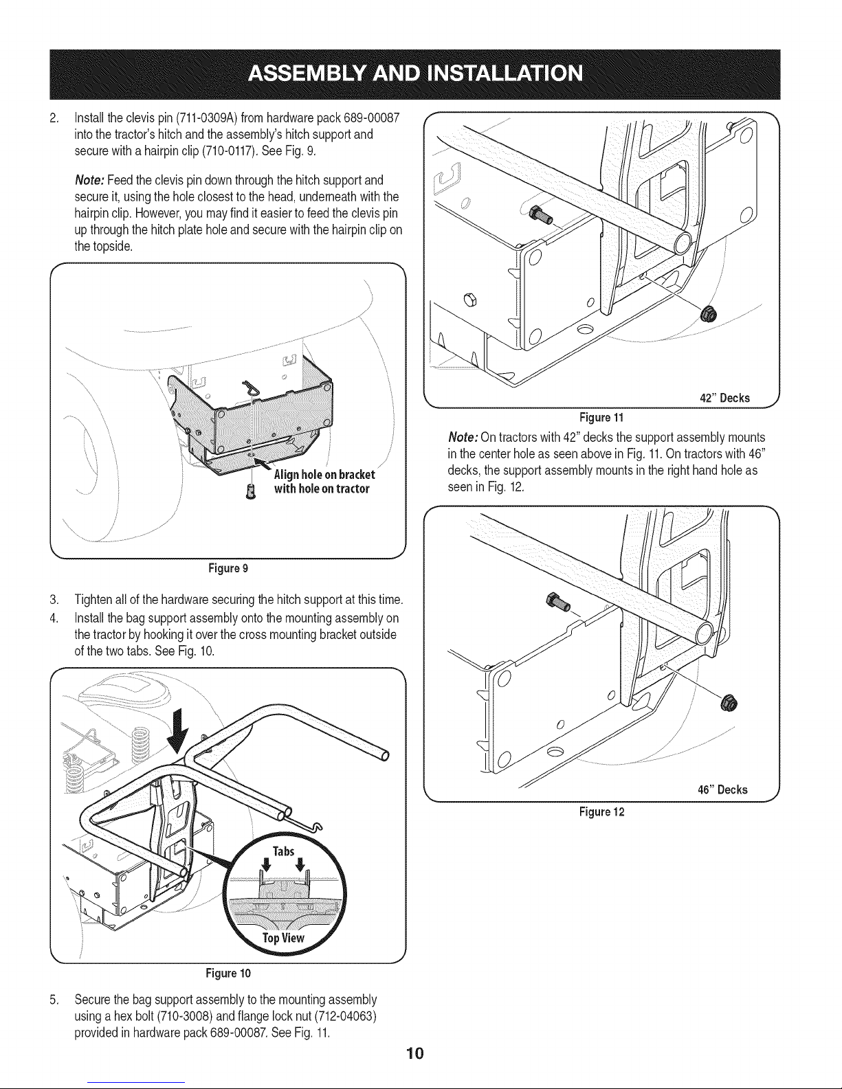
.
Installtheclevispin(711-0309A)fromhardwarepack689-00087
intothe tractor'shitchandthe assembly'shitchsupportand
securewitha hairpinclip(710-0117).SeeFig.9.
Note: Feedtheclevispindownthroughthehitchsupportand
secureit, usingtheholeclosesttothe head,underneathwiththe
hairpinclip.However,you mayfinditeasierto feedtheclevispin
upthroughthe hitchplateholeandsecurewiththehairpinclipon
thetopside.
/
/
Figure9
.
Tightenallofthe hardwaresecuringthehitchsupportatthistime.
4.
Installthe bagsupportassemblyontothe mountingassemblyon
thetractorbyhookingitoverthecrossmountingbracketoutside
ofthe twotabs.See Fig.10.
\
\
/
/
\
L_ 4211Decks _
Figure11
Note:Ontractorswith42" decksthe supportassemblymounts
in thecenterholeasseenabovein Fig.11.Ontractorswith46"
decks,thesupportassemblymountsinthe righthandholeas
seenin Fig.12.
Figure10
.
Securethebagsupportassemblytothe mountingassembly
usinga hexbolt (710-3008)andflangelocknut(712-04063)
providedinhardwarepack689-00087.SeeFig.11.
46" Decks
Figure 12
10
Page 11

AssemblingRemaining Bagger Components
Nowthatthe mountingbracketsareassembledandare inplaceon
thetractor,followthesestepstoassembletheremainingbagger
components.
1. Snapthe upperchutesupportinplacebyfirstclippingthe side
portionontothebinsupportrail.Aligntheedgeofthesnap
featurewith theredline(1),as showninthe insetof Fig.13.
2. Snapthefrontportionofthe upperchutesupporttothebin
supportrailas seenin2ofFig. 13.
f
\
Makesurescreensits
underthe cover'slip
Figure15
Installthegrasscatchercoverontothebin supportassembly,as
seeninFig.16.Thegrasscatchercovergoesinsideofthetwo
mountingtabsonthe binsupportassembly.
Figure13
3. Installthegrasscatchercoverscreenintothebaggercoverby
firstinsertingtheendclosestto thesidewiththecutoutintothe
mountinghole,asinFig. 14.Makesuretofeedthe screenunder
thelip,asinFig. 15.
4. Clipintheotherside byflexingthescreenand pushingitdown
intotheprovidedcutouthole.SeeFig.15.
Figure 16
Slidethehingepin intotheholelocatedonthemountingtab,as in
Fig.17onthefollowingpage. Usethecut-outwindow(Seeinset
inFig. 17)to lineupthehingepinontheotherside andpushpin
all thewayinuntilitreachestheend-stop.Atthispointthe pin
clips intoplaceandissecuredbyatab inthe baggercover.See
Fig.18.
Figure14
11
Page 12

Figure17
J
Figure18
Opengrasscatchercoverby pushinginontherear,right-sidetab
withyourright-hand,asseenin 1of Fig.19,andliftingwithyour
left-handintherearcenter,2.
.
Installbothgrassbinsontothebinsupportassemblybyinserting
thefrontedgeinfirst (1),asseen in Fig.20,andsettingthe back
edgedown(2) untilit fits intotheassembly.
/
Figure20
NOTE:Thesideof the grassbinswiththetight meshisintendedtobe
positionedfacingforward.
.
Installoneof the rubberchutestraps(723-04008A)ontothe
dischargechuteelbowusingoneofthe suppliedclevispins(711-
05063),washer(736-0204)andBow-tiecotterpins(710-04040)
fromhardwarepack689-00092B.SeeFig.21. Securetheend
ofthe straputilizingtheholefurthestfromtheend,and insertthe
torsionspringhook(732-04510A)fromthesamehardwarepack
intotheotherendof the rubberstrap.
10.
Installtheattachmentpin(711-05049)andtwoflatwashers(736-
0176),fromhardwarepack689-00092B,upintothechuteelbowand
securewithaflangelocknut(712-3027),asseeninFig.21.
11.
Installtheshoulderbolt(738-0754)intothechuteelbowfromthetop
sideandsecureinsidethechuteelbowusingaflangelocknut(712-
04063)fromthe samehardwarepack(689-00092B).SeeFig.21.
Figure19
12
Figure21
Page 13

12. Installthegrass-catcherpin(911-04069)fromhardwarepack689-
00092Bintotheholeprovidedintheupperportionofthechuteelbow
andsecurewithaflangelocknut(712-3027).SeeFig.22.
Figure 22
13.
Installrubberstrap(723-04008A)ontothechutetubeextensionusing
clevispin(711-05063),flatwasher(736-0204)andbow-tiecotterpin
(710-04040)fromhardwarepack689-00092B.Attachtheendwith
theholeclosesttotheendofthe strap,asseeninFig.23.Thiswill
makeit easiertograbontothestraptopull,stretchandhookontothe
grass-catcherpininstalledonthechuteelbowinthepreviousstep.
f
Figure24
Figure23
14.
Withthetractor'sdischargechuteraisedupandheldopen,
installthechuteelbowoverthe chuteopeningbyplacingthe
deckmountingpinin theholeprovided,as shownin Fig.24,then
securetheelbowto thedeckbyhookingthe retainerstraphook
overthe deckwheelmountingbracketasshownin Fig.25A.
Note: Ondeckswithoutdeckwheels,hookthe retainerstrap
intothe holeprovidedintheflangeon thefront-sideofthecutting
deckasshownin Fig.25B.
Figure25A
J
Figure25B
13
Page 14

15.
Installthechutetubeextensionontothe chuteelbowbyliningup
thetabsand slidingtheadapteroverthechuteelbow,as inFig.
26.Securethechuteadapterbystretchingthechutestrapand
hookingitontothe grass-catcherpin previouslyinstalled.
Figure 26
16.
Peelthebackingoff oftheself-adhesivefoamstrip(721-04388)
thathasbeenincludedwithyourgrasscollector.Applyitto the
upperchute,flushagainstthe flangeasshownin Fig.27.
Flange
Figure28
NOTE:Thegrooveonthe upperchuteshouldbealignedwiththe
upperchutesupport,asseenin theinsetofFig.29.
Figure27
17.
Withthegrasscatchercoveropen,installthedischargechute
overthe chuteextensiontube,as seenin Fig.28,and restthe
topendinto the upperchute supportinstalledon the right-hand
sideof the binsupportassembly.See Fig.29.
I
Figure29
14
Page 15

Bagger Operation 3.
NOTE:Whenbothgrassbinsare full,placethetractoron afirm, level
surface,disengagethePTO(BladeEngage),turnthe tractorengine
offand settheparkingbrake.
1. Fliptheseatup.
2. Opengrasscatchercoverbypushinginon therear,right-sidetab
withyourright-hand,asseenin 1of Fig.27,and liftingwithyour
left-handintherearcenter,2.
4. Emptythegrassclippingsat a properdisposalsite.Graspthe
5. Replacegrassbins,closelid,flipdownseat,restartyourtractor
J
Figure27
Removethegrassbinsbyliftingthemup (1in Fig.28)andaway
fromthebinsupportassembly(2).
f
Figure28
handleatthe bottomofthebinwithonehand,andwiththe other
handsteadythebin,andemptythecontents.
and resumecuttingyourgrass.
15
Page 16

2
31
@
\
14
15
16
Page 17

m
1
2
3
4
5
6
7
8
9
10
11
12
13
14
15
16
17
18
19
2O
21
22
23
24
25
26
27
28
29
30
31
32
33
34
35
36
37
38
39
931-04291
931-04292
731-06497
731-06504
710-0276
710-3008
711-0309A
911-04069
711-05049
711-05063
712-04063
712-3027
714-0117
714-04040
723-04008A
731-06099B
731-06610
732-04510A
736-0204
736-0176
738-0754
N/A*
N/A*
N/A*
783-05887
964-04096A
683-04461A-0637
683-04519-0637
711-04988
735-0246A
689-00101
710-04484
711-0332
712-04065
914-0145
738-04267
783-05889A-0637
783-05890A-0637
721-04388
UpperChuteAssembly
DoubleBaggerCoverAssembly
UpperChuteSupport
BaggerCoverScreen
CarriageScrew,5/16-18x 1.00"
HexHeadScrew,5/16-18x .75"
ClevisPin, .62"Dia.
Grass-catcherPin,1/4-20
AttachmentPin,1/4x 0.66 Lg.
ClevisPin,5/16x .75Lg.
FlangeLockNut,5/16-18
FlangeLockNut, 1/4-20
InternalCotterPin,.148x 3.00
Bow-TieCotterPin,72
ChuteStrap,6.00Lg.
BaggerDischargeChute,Elbow
BaggerChuteAdapter,7In.
TorsionSpringHook
FiatWasher,.344x .62x .033
FiatWasher,.265x .938x .120
ShoulderScrew,.437x .54
MountingBracket,RH
MountingBracket,LH
UniversalMountingBracket
UniversalSupportBracket
Grass-bagAssembly
DoubleBagSupportAssembly
VerticalSupportBracket
CoverHingePin
EndPlug
MountingBracketKit(incl.ref.22, 23, 24)
TapScrew,5/16-18x .750
ClevisPin, .50x .78
FlangeLockNut,3/8-16
ClickPin,.092x 1.64Lg.
ShoulderScrew,.625x .412
MountingBracket,RH
MountingBracket,LH
Self-AdhesiveFoamStrip
*AvailableasanassemblyonlyorderRef.31
17
Page 18

Craftsman Total Garantia
CraftsmanSiesteproductofalladebidoa undefectodematerialo manode obradentrodeunaSoa partirde la fechadecompra,el retornoa
cualquierfiendaSearsocualquierotraCraftsmande salidaenlosEstadosUnidosparalasustituci6ngratuita.
EstagaranfiacubreQnicamentedefectosde materialy manodeobra.Searsnopagar&por:
• Sustituci6ndelas bolsas,quesonfungiblesquepuedenIlevaracabo apartirdela utilizaci6nnormalenelperiodode
garanfia.
• Lasreparacionesnecesariasa causade accidenteo el fracasoparaoperaro mantenerelproductodeacuerdocontodaslas
instruccionessuministradas.
Estagarantiaseaplicaa s61o90diassiesteproductoes utilizadocadavezconfinescomercialeso alquiler.
Estagaranfias61ose aplicamientrasesteproductoseutilizaen losEstadosUnidos.
Estagaranfialeotorgaderechoslegalesespedficos,y ustedtambi_npuedetenerotrosderechosquevariande unestadoa otro.
Sears BrandsManagementCorporation., Hoffman Estates,IL 60179
© KCDIRLLC 18
Page 19

Lapresenciadeeste sirnboloindicaque setratadeinstrucciones
irnportantesde seguridadquesedebenrespetarparaevitar
ponerenpeligrosuseguridadpersonaly/omaterialy lade otras
personas.Leay sigatodaslasinstruccionesdeestemanualantes
de poneren funcionarnientoestarnAquina.Si no respetaestas
instruccionespodriaprovocarlesionespersonales.Cuandoveaeste
sirnbolo,ipresteatenci6na la advertencia!
EstarnAquinarueconstruidaparaseroperadadeacuerdocon
lasreglasde seguridadcontenidasenestemanual.AIigualque
concualquiertipodeequipornotorizado,undescuidoo errorpor
partedeloperadorpuedeproducirlesionesgraves.EstarnAquina
escapazde arnputarrnanosy piesy dearrojarobjetoscongran
fuerza.Deno respetarlasinstruccionesdeseguridadsiguientesse
puedenproducirlesionesgraveso larnuerte.
PROPOSICION 65 DE CALIFORNIA
Elescapedel motordeesteproducto,algunosdesuscornponentes
y algunoscornponentesdelvehiculocontieneno liberansustancias
quirnicasqueelestadodeCaliforniaconsideraquepuedenproducir
cancer,defectosdenacirnientouotrosproblernasreproductivos.
Losbornesdela bateriay losaccesoriosalinescontienenplornoy
cornpuestosde plorno,sustanciasquirnicasqueseg_nIoestableci-
do porel Estadode Californiacausancancery daSosenel sisterna
reproductivo.Ldveselasmanos despu_sde estaren contacto
con estoscomponentes.
Fun¢ionamiento general
1. Lea, comprenda y respete todas las instrucciones que figuran
en el equipo yen los manuales antes de intentar armarlo y
hacerlo funcionar. Guarde este manual en un lugar seguro
para consultas futuras y peri6dicas, asi como para solicitar
repuestos.
2. Para ayudar a evitar una lesi6n pot contacto con las cuchillas
o con un objeto que sea arrojado, mantenga a las personas
que observan, a los ayudantes, ni_os y mascotas alejados a no
menos de 25 metros de la m_quina mientras est& funcionando.
Detenga la m&quina si alguien entra en la zona.
3. Revise minuciosamente el _irea donde se va a usar el equipo.
Retire todas las piedras, palos, cables, huesos, juguetes y otros
objetos extra6os que podrian set recogidos y arrojados por la
acci6n de las cuchillas. Los objetos arrojados por la m&quina
pueden causar lesiones graves.
4. Para protegerse los ojos, utilice siempre galas o lentes de
seguridad mientras opera la m&quina o mientras la ajusta
o repara. Los objetos arrojados que rebotan pueden causar
lesiones oculares graves.
5. Nunca opere la cortadora de c_sped sin tenet bien colocada
la cubierta de descarga o el colector de c_sped. Si falta o
est_ da6ada la cubierta de descarga oun componente del
accesorio embolsador puede resultar en lesiones por contacto
con la cuchilla o con objetos arrojados.
6. No ponga las manos ni los pies cerca de las piezas rotatorias ni
debajo de la plataforma de corte. El contacto con las cuchillas
puede resultar en la amputaci6n de una mano o pie.
7. Apague el motor de la cortadora de c_sped y espere que
las cuchillas se detengan totalmente antes de desbloquear
la abertura de descarga de la cortadora o las piezas de la
embolsadora.
Su responsabilidad--Restrinja el usode estarnAquina
rnotorizadaa laspersonasque lean,cornprendany respetenlas
advertenciase instruccionesqueaparecenenestemanualyen la
rnAquina.
iGUARDEESTASINSTRUCCIONES!
8. Reduzca la velocidad antes de girar. Opere la m&quina de
forma pareja. Evite el funcionamiento err_itico y la velocidad
excesiva. Tenga en cuenta que el accesorio colector de c_sped
puede afectar las caracteristicas de manejo de su cortadora.
Fundonamiento en pendientes
Las pendientes son un factor importante en los accidentes
ocasionados pot p_rdida de control y vuelcos que pueden causar
lesiones graves e incluso la muerte. Los accesorios tambien pueden
afectar la estabilidad de la m&quina. La operaci6n en pendiente
requiere mayor precauci6n.
Para seguridad, use el medidor de pendientes que se incluye como
parte de este manual para estimar el _ingulo de la pendiente antes
de hacer funcionar la m_iquina en una zona inclinada. Si la pendiente
es mayor a 10 grados en el medidor, no opere la cortadora con el
accesorio embolsador en ese sector, pues podria causar lesiones
graves.
HagaIo siguiente:
1. Corte hacia arriba y abajo de las pendientes, no en forma
transversal. Tenga sumo cuidado al cambiar de direcci6n en
una pendiente.
2. Est_ atento a los hoyos, surcos, baches, rocas, u otros objetos
ocultos. El terreno desnivelado puede voltear la m&quina. El
pasto alto puede ocultar obst_iculos.
3. Conduzca a baja velocidad. Elija una velocidad Io
suficientemente baja como para no tener que detenerse
o cambiar de marcha mientras est,1 en la pendiente. Los
neum_ticos pueden perder tracci6n en las pendientes aun
cuando los frenos funcionen correctamente. Mantenga
la m&quina siempre en velocidad cuando desciende una
pendiente, para poder frenar con el motor.
19
Page 20

4. Siga las recomendaciones del fabricante sobre pesos y
contrapesos de las ruedas, para mejorar la estabilidad.
5. Haga que todos los movimientos en las pendientes sean
lentos y graduales. No cambie repentinamente lavelocidad
ni la direcci6n. Un frenado o cambio de velocidad repentinos
pueden causar que el frente de la m_quina se levante y d6 una
voltereta hacia atr_s, Io que podria causar lesiones graves.
6. Evite arrancar o detenerse en una pendiente. Silos neum_ticos
pierden tracci6n, desenganche las cuchillas y descienda
lentamente la pendiente.
Nohaga I0siguiente:
I. No gire en una pendiente a menos que sea imprescindible. De
ser posible, gire lenta y gradualmente cuesta abajo.
2. No corte el c_sped cerca de barrancos, zanjas o terraplenes. La
cortadora de c_sped podria volcarse repentinamente si una de
las ruedas estuviera sobre el borde de un acantilado o zanja, o
si un borde se desmoronara.
3. No intente estabilizar la m_quina poniendo el pie en el suelo.
4. No utilice un colector de c_sped en pendientes empinadas.
5. No corte el c_sped humedo. Una reducci6n en tracci6n puede
causar derrapes.
Servid0 general
I. Antes de limpiar, reparar o inspeccionar la m_quina,
compruebe que las cuchillas y todas las piezas m6viles se
hayan detenido. Desconecte el cable de la bujia y p6ngalo
haciendo masa contra el motor para evitar que arranque
accidentalmente.
2. Mantenga todas las tuercas, pernos y tornillos bien ajustados
para asegurarse de que el equipo est_ en condiciones seguras
de operaci6n.
3. Nunca intente violar el sistema de bloqueo de seguridad u
otros mecanismos de seguridad de la cortadora. Controle
peri6dicamente que funcionan correctamente.
4. No intente nunca hacer ajustes o reparaciones a la cortadora
mientras el motor est_ en marcha.
5. Los componentes del colector de c6sped y la cubierta de
descarga est_n sujetos a desgaste y daffos que podrian dejar
expuestas piezas que se mueven o permitir que se arrojen
objetos. Para proteger su seguridad, verifique frecuentemente
todos los componentes y reempl_celos inmediatamente
0nicamente con piezas de los fabricantes del equipo original
(O.E.M.) indicados en este manual. El uso de piezas que no
cumplen con las especificaciones del equipo original puede
resultar en rendimiento inadecuado y puede poner en peligro
la seguridad.
6. Mantenga o reemplace las etiquetas de seguridad y de
instrucciones seg0n sea necesario.
Simbolosde segufidad
En esta p_gina se presentan y describen los simbolos de seguridad que pueden aparecer en este producto. Lea, entienda y cumpla todas las
instrucciones incluidas en la m_quina antes de intentar armarla y utilizarla.
LEA LOS MANUALES DEL OPERADOR
Lea, entienda y cumpla todas las instrucciones incluidas en los manuales antes de intentar armar la
unidad y utilizarla.
DETENCION
Apague el motor antes de abrir la cubierta de la embolsadora.
iADVERTENCIA! Su responsabilidad--Limiteel usodeestam_.quinamotorizadaalas personasquelean,comprendany
cumplanlasadvertenciaseinstruccionesqueapareceneneste manualyen lam_.quina.
iGUARDEESTASINSTRLICCIONES!
2O
Page 21

(ACEPTAR)
Figura1
"" 10° Pendiente
10° Pendiente
(DEiVIASlADO ESCARPADO)
Figura2
0oI[nea
- - " "" - _ .-...diSC°ntinua
US0DEESTEPENDIENTEDECALIBREPARADETERiVIINAR
SIUNAPENDiENTEESDEIV1ASiADOESCARPADOPARAUNAOPERACi(_NSEGURA!
Paracomprobarlapendiente,hagaIosiguiente:
1. Borrarestap_.ginay dobleaIo largodelalineadiscontinua.
2.
3.
4.
Localizarun objetoverticalsobreo detrJ.sdelapendiente(unposte,unedificio,unavalla,un _.rbol,etc.)
Alineecadaladodependientedecalibreconelobjetovertical(consultarFigura1 andFigura2 ).
Ajusteel pendientedecalibrearribao haciaabajohastalostoquesesquinaizquierdael pendiente
(consultarFigura1andFigura2).
Sihayun espaciopordebajodela pendientedecalibre,elpendienteesdemasiadoescarpaporoperaciOn
segura(consultarFigura2 above).
Las pendientesson un factor importante relacionadocon un vuelco y renovaci6ndelos accidentesque puedenprovocar lesionesgraves o la muerte.
No utilicela m_.quinaenpendientes de m_.sde 10grados.Todos pendientesrequiere mayorprecauci6n.Si no puede retrocederen la pendiente o si se
siente inseguroen ella, no la recorte. Siempre corteel cespedarriba y abajo laspendientes, nunca en toda la superficiede la cuesta.
Page 22

Antesdecomenzarlainstalaci6n,retiretodaslas piezasdela cajaparaasegurarsedequefienetodo,Elcontenidodela cajase muestraa
confinuad6n,Estekit induyedos paquetesde herrajesquesedetallanenlap_.ginasiguiente,
• Kitde lam_nsuladeenganche(3soportesy paquete de herrajes)
Conjuntode montaje(2soportesyherrajes- *ParaModelosLT)
• Extensidndetubode canal
• Soportede enganche
• Cododecanalde descarga
• Pantalladela cubiertadelcolectordec_sped
• AutoadhesivasdeespumadeGaza
• Soportedecanalsuperior
• Pasadorde cubiertade bisagra
Soportevertical
• Unidadde soportedelasbolsas
Trespaquetesde herrajes(Detalladose ilustradosen lapagina siguiente)
• Cubiertadelcolectorde cesped
• Dosunidadesparabolsasdecesped
• Tubode canalsuperior
Kit de la m_nsula de enganche
(3 piezas y paquete de herrajes) _\_
Montajederecho(789-00052)
Montajeizquierdo(789-00054)
Mensuladeuni6nposterior
(789-00053)
Pernosdelcaro(4)
(710-0276)
Tuercasde seguridadconbrida
(4)(712-04063)
_ j_ Conjunto de montaje _
__ Soportederecho (783-05889-0637)
Soporte izquierdo(783-05889-0637)
(4) Pernoshexagonales(710-04484)
(2) pernos de reborde (738-04267)
(2)Tuercasde seguridad con reborde (712-04065)
(2) Pasadores de horquilla (711-0332)
*ParaModelosLT*
(2) Trinquetes(914-014_
Soporte de
Codo de canal
de descarga
(731-06099B)
enganche
(783-05_
Pantalla de la
tubo de canal (731-06504)
(731-06610)
Conjuntos de
bolsa para
recorte de
c_sped
(664-04096A) _
Pasador de cubierta_
de bisagra _ _,._
_,(711-04988)_" _.. "_
Soportevertical f37" aelasbolsas
(683-04519-0637) _._,'_'_ (683-04461A-0637)
Cubierta del
colector de c_sped
(931-04292)
Soporte de canal
_7_3 superi°r
1-06497)
Autoadhesivas de
espuma de Gaza
(721-04388)
Tubo de canal
superior
(931-04291)
J
22
Page 23

Estejuegocolectordec_spedse enviaconunpaquetesdeherrajessueltosincluidos. Porfavorcontroleel contenidodelospaquetesconlas
ilustracionessiguientes.Lacantidadde cadaelementoapareceentrepar_ntesisy el n0merodepiezacercadecadaelemento.
ParaConjunto de montaje -- 689-00080A ParaCanal de Descarga-- 689-00092B
1) (1)
(2) 723-04008
711-05063
710-3008
710-0276
(2)
(2)
736-0204
712-04063
(2)
Para Kit de la M_nsula de Enganche -- 689-00087
I
I
(1)
714-04040
710-3008
712-04063
4)
(4)
711-0309A
(1)
©
714-0117
(1)
1)
736-0176
[_(1)
911-04069
(2)
712-3027
)
732-04510A
711-05049
712-04063
23
738-0754
Page 24

Identifiqueel rnodelo de tractor
Estemanualest,.dise_adoparala instalaci6ndeestaunidadde
ensacadonuevasenvariosdiferentesrnodelosde tractores.Es
irnportanteparaustedparadeterrninarcu_.lesel rnodelodetractor
queustedtiene.Unavezqueestose conoce,sigael conjuntode
instruccionespertinentesen lasp_.ginassiguientes.
Paradeterrninarqu_rnodelodepilotoquetiene,rnirarala placadel
rnodelodelciclista,que seencuentradebajodelasiento.Sirnplernente
darla vueltaal asientohaciaarribay busquelaplacadelrnodelo,que
incluir_,el nOrnerode rnodeloy nOrnerodeserie.
Tractores de la serie LT
Siest,. rnontandoestaunidadernbolsadoraparasuusoencualquiera
de losrnodelosanteriores,tendr_,queinstalareltractorde dos
soportesdernontajeenvasadoensu kitde laernbolsadora.Siva a
instalarestaunidadernbolsadoraencualquierottotractor,hayque
saltarseesospasosy pasara rnontarlossoportesdernontaje.
Parainstalarestasrn_nsulasen untractordela serieLT,siguaestos
pasos:
1. Instaleunpernoconrebordedelpaquetedeelernentosen c_.da
rn_nsula,ajust_.ndolosconlastuercasde seguridadconbridaque
tarnbi_nseencuentranenel paquete.ConsultelaFig.1.
2. Instaleunpasadoresdehorquilladelpaquetedeelernentosen
c_.darn_nsula,segurocon lastrinquetesconbridaquetarnbi_n
seencuentranen el paquete.Consultela Fig.1.
3. Saquey descartelosdostornillosdel chasisinferiorcornose
rnuestraen la Fig.2.
f
Figure2
Arrnadode las rn_nsulas de montaje
Paraarrnarla unidadde rnontajedelaernbolsadora,Iocaliceelkit de
la rn_nsulade engancheysigaestospasos:
Unalas rnensulasde enganchede arnbosladosala rnensulade
uni6ntraserauniversalconlosdos pernosdelcarro(710-0276)y
lastuercasde seguridadconbrida(712-04063)ernpacadascon
lasrn_nsulasde rnontaje.Coloquelasrn_nsulasconlosganchos
de lasrn_nsulasdelladoderechoy ladoizquierdodela podadora
rnirandohaciaabajo,ylasleng_Jetasdela rn_nsulade uni6n
traserauniversalrnirandohaciaarriba.Veala Fig.3.
Figura1
Figure3
24
Page 25

Nora:Estaunidaddelarn_nsulade rnontajeuniversalest,.dise_adao
parafuncionarconotrosaccesorios,cornoeseljuegodecontrapesos
queseusajuntoconlacuchillaparanieveoelaccesorioquitanieve.
Utilicelainforrnaci6ndecontactodelatapadeestemanual,o
cornuniqueseconlatiendadondeadquiri6elequipo,paraobtenerrn_.s
inforrnaci6nsobrelosaccesoriosdisponiblesparasutractorenparticular.
2. Volteela unidaddel revesy montela rn_nsulade soporte
deengancheala unidaddernontajeconloscuatropernos
hexagonales710-3008y lastuercasdeseguridadconbrida
712-04063del paquetedeherrajes689-00087..
• ParaModelosLTSerie:Veala Fig.4.
.j,:¢/J_
o__ •................_
LTSerie
Figure4
• ParaModelosYT Sede:Yeala Fig.5.
f
Figure6
k,_ YTSerie
Figure5
Nora: AIacoplarel soportedeenganche,convienenoajustar
totalrnentelarn_nsulatodavia.Estofacilitate,el procesode rnontaje
rn_.sadelante,cuandose deber_,ajustara rondola rn_nsuladel
soportedeenganche.
Armadode la unidad de soporte de los cubos
Ubiquelarn_nsulade soporteverticalyla unidadde soportedelos
cubos.Sigaestos pasosparael arrnado:
1. Apoyelapartesuperiorde la unidadde soportedeloscubos
paraabajoconla porci6ndelarn_nsuladernontajehaciaarriba.
2. Inserteel extrernoranuradodela rn_nsulade soportevertical
enla unidadedesoportede loscubos,cornoenla Fig.6, y fije
conunpernodel carro(710-0276)y unatuercade seguridadcon
brida(712-04063)quevienenconla rn_nsulade soportevertical.
Veala Fig.7.
Figure7
Monte la unidad sobre el tractor
Instalelaunidaddernontajesobreel tractordeestarnanera:
1. Coloquelosextrernosconganchode launidadde rnontajede
ernbolsadosobrelos pernoscon reborde,cornoenla Fig.8,
sobreeltractoryalineeel orificiodel soportedeenganchede la
unidadde rnontajeconel orificiodelenganchedel tractor.
....s
................................................
'x
\
Figure8
25
Page 26

.
Instaleelpasadorde horquilla(711-0309A)delpaquetede
herrajes689-00087enel enganchedeltractoryel soporte
de enganchede la unidadyfijeconunachavetadehorquilla
(710117).Veala Fig.9 enla p_.ginasiguiente.
Neta:El pasadordehorquillasepuedepasarhaciaabajopotel
soportede engancheusandoel orificiom_.scercanoa lacabeza,y
asegurarloporabajocon la chavetade horquilla;opuederesultarm_.s
f_.cilpasarlohaciaarribaporla placade enganchey asegurarloconla
chavetaenlaparte superior.EsteOltimom_todosueleserelpreferido
yaquepuedeserm_.sf_.cilinsertarel brochede horquilla.Cualquiera
de losdoses correcto,ladecisi6ndependedela preferenciadel
operador.
Alineeel orificiode
4
lam_nsulaconeldel
tractor ...............
iiiiiilliiiiii!iiiiiii! !' i i' iiiiiiiiiiliiilif!ii
.....i_iiiiii!_ii!i_!ili!iiiiiiiiii!i_iiiiililiiii!iiiiiiiii_iiii_iiii_ii_ii_ii_iiiiiii_iiiiiiii!i!i'_
j
..............J
3. Ajusteahoratodoslosherrajesquesujetanelsoportede
enganche.
4. Instalela unidadde soportede las bolsasenla unidadde
montajedeltractorenganch_.ndolosobrela m_nsulade montaje
cruzadoporfuerade lasdosleng(Jetas.Veala Fig.10.
5. Fijela unidaddesoportede lasbolsasa launidadde montaje
conlos pernoshexagonales(710-3008)y latuercade seguridad
conbrida(712-04063)provistaenel paquetedeherrajes689-
00087.Veala Fig.11.
f
,/
Figura9
Figura 10
/
/
Cubiertas 42"
Figura 11
Nota:Enlostractoresconplataformade42" la unidaddesoporte
semontaen elorificiocentralcornosevearribaenla Fig. 11.Enlos
tractorescon plataformade 46"la unidadde soportese montaenel
orificioderechocomose veen la Fig.12.
Cubiertas 46"
Figura12
26
Page 27

Armadodel resto de los componentes dei recolector
Unavezquelas rn_nsulasdernontajeest_.narmadasy colocadasen
el tractor,sigaestos pasosparaarrnarel restodeloscornponentesde
la ernbolsadora.
1. Calcea presi6nelsoportedelcanalsuperiorcolocandoprirnero
el lateralsobreel rielde soportedelcuboconel hordequecalza
a presi6nalineadoconla linearoja(1),cornose ve enel recuadro
dela Fig.13.
2. Calceapresi6nlapartedelanteradel soportedelcanalsuperior
enel soportedelcubo,cornoseve en2 de la Fig.13.
F *"
f
Aseg_resequelapantalladescansa
bajoel rebordedelacubierta
Figura15
5. Instalela cubiertadelcolectordec_spedenla unidadde soporte
del cubo,cornoseveen la Fig.16.Lacubiertadelcolectorde
cespedvadentrode lasdosleng_Jetasde rnontajesobrela
unidadde soportede loscubos.
Figura13
3. Instalelapantalladelcolectordec_spedenla cubiertadela
ernbolsadora,insertandoprirneroel extrernorn_.scercanoallado
quetieneel recorteenel orificiode rnontaje,cornoenla Fig.14.
AsegOresede pasarla pantallapordebajodelreborde,cornoen
la Fig.15.
4. Calceelotroladoflexionandola pantallayernpuj_.ndoladentro
del recorteprovisto.Veala Fig. 15.
Figura 16
Desliceelpasadordehorquillaenel orificioubicadoenla
lengiJetade rnontaje,cornoen la Fig.17de la p_.ginasiguiente.
Usela ventanarecortada(veael recuadrodelaFig. 17)para
alinearel pasadordehorquilladel otroladoyernpOjelohasta
que Ileguealtope.Enestepuntoel pasadorcalzaensu posici6n
y quedaaseguradoporunaleng(Jetadela cubiertadela
ernbolsadora.Veala Fig.18.
Figura14
27
Page 28

Figura17
Figura18
7. Abralacubiertadelcolectorempujandohaciaadentroenla
lengiJetaposteriorderechaconlamanoderecha,comose ve en
1de la Fig.19,y levantandoconla manoizquierdaenel centro
de lapa[t# poste[io[,2.
,
Instaleamboscubosenla unidadde soportedelos cubos
insertandoprirneroelhordedelantero(1),comose veenla Fig.
20,y bajandoel hordeposteriorhastaquecalceen la unidad.
Figura20
NOTA:Elcostadodeloscubosquetienela redapretadadebe
colocarcemirandohaciaadelante.
9. Instaleunade lastirasde cauchodelcanal (723-04008A)en
el cododelcanaldedescargacon unodelos pasadoresde
horquilla(711-05063),arandela(736-0204)y pasadordechaveta
con uni6ncurva(7104040)provistosenel paquetede herrajes
689-00092B.Veala Fig.21. Sujeteel extremode latirausando
el orificiom_.salejadodelextrerno,y luegoinserteel ganchodel
resortedetorsi6n(732-04510A)del mismopaquetedeherrajes,
en el otroextremode la tirade caucho.
10. Instalelospasadoresdernontajedelaplataforma(711-05049)dentro
delcododelcanaldoslaarandelaplana(736-0176)delpaquetede
herrajes689-00092B,yfijeloconunatuercadeseguridadconbrida
(712-3027),comoseve enlaFig.21.
11. Instaleunpernoconreborde(738-0754)enelcododelcanaldesde
arribaysuj_telodentrodelcodoconunatuercadeseguridadcon
brida(712-04063)delmismopaquetedeherrajes(689-00092B).
VealaFig.21.
Figura 19 Figura 21
28
Page 29

Instaleelpasadordelcolector(911-04069)delpaquetedeherrajes
689-00092Benelorificioqueseencuentraenlapartesuperiordel
cododelcanaly suj_teloconunatuercadeseguridadconbrida
(712-3027).VealaFig.22.
,. j
Figura22
13.
InstalelaIra decaucho(723-04008A)enlaextensi6ndeltubodel
canalconunpasadordehorquilla(711-05063),unaarandelaplana
(736-0204)yunpasadordechavetaconuni6ncurva(7104040)del
paquetedeherrajes689-00092B.Unaelextrernoconel orilciom_.s
cercanoalextrernodelaIra, comoseveenlaFig.23.Asiser_.m_.s
f_.cilagarrarlaIra parajalarla,estirarlayengancharlaenel pasador
delrecolectordecespedinstaladoenelcododelcanalenelpaso
anterior.
Figura23
14.
Conel canaldedescargadeltractorelevadoyabierto,instaleael
cododelcanal sobrelaaberturadelcanalcolocandoel pasador
demontajede laplataformaen elorificioprovisto,comoenla
Fig.24;luegofije el codoa la plataformaenganchandola tira
de retenci6nsobrela m_nsulade montajede lasruedasdela
plataforma,comose veenla Fig.25A.
Nora: en lascubiertasde lasruedas,sin cubierta,ganchode la correade
retenci6nenel orificioprevistoen la bridaenel ladofrontalde la plataforma
decorte,como se ve en la Fig. 25B.
Figura25
J
Figura25B
29
Page 30

15. Instalelaextensi6ndeltubo delcanalenelcodoalineandolas
lengQetasydeslizandoel adaptadorsobreel codo,comoseve
en laFig.26.Asegureeladaptadorestirandola tiradelcanaly
enganch_.ndolaenel pasadordelcolectordecespedpreviamente
instalado.
Figura26
16. Pelarel respaldofuerade lafranjadeespurnaauto-adhesivo
(721-04388)que hasidoincluidaconelcolectordec_sped.
Apliquea latolvasuperior,aras conlabridacornosernuestraen
lafigura.27.
Brida
/
Figura27
17.
Conlacubierta delcolectorabierta,instaleel canalde
descargasobreel tubodeextensi6ndel canal,cornoseveen
la Fig.28,y hagadescansarla partesuperiorsobreel soporte
superiordel canal,a la derechedela unidadde soportede los
cubos.Veala Fig.29.
Figura28
Figura29
NOTA:La ranuradelcanalsuperiordebeestaralineadaconel
soportesuperiordelcanal,comose veen el recuadrodela Fig.28.
3O
Page 31

Funcionamientode laembolsadora
NOTA:Cuandolosdos cubosparacespedest_nIlenos,coloqueel
tractorsobreunasuperficiefirrney nivelada,desenganchela torna
defuerza(PTO),apagueel motordeltractorycoloqueelfrenode
estacionarniento.
1. Volt,eel asientohaciaarriba.
2. Abralacubiertadecespedernpujandoen lapartetrasera,lado
derechodelafichacon su rnanoderecha,cornose veenla figura
1.29, yde levantarconla rnanoizquierdaen elcentrode la parte
trasera,2.
3. Elirninarloscubosdelahierbaporlevantarlashasta(1en lafigura.
30) yfuerade laasarnbleadeapoyobin(2).
Figura30
4. Vacielosrecortesdepastoen unprediode elirninaci6n
adecuado,use larnanijadelrondode cadacubode c_sped.Para
vaciarel contenidosostengafirrnernenteelcubo.
5. Vuelvaa colocarloscubos,cierrela tapa,volt_eel asientohacia
abajo,arranqueeltractorycontinOecortandoel c_sped.
Figura 29
31
Page 32

Your Home
For troubleshooting, product manuals and expert advice:
managernylife
www.managemylife.com
For repair - in your home - of all major brand appliances,
lawn and garden equipment, or heating and cooling systems,
no matter who made it, no matter who sold it!
For the replacement parts, accessories and
owner's manuals that you need to do-it-yourself.
For Sears professional installation of home appliances
and items like garage door openers and water heaters.
1-800-4-MY-HOME ® (1-800-469-4663)
Call anytime, day or night (U.S.A. and Canada)
www.sears.com www.sears.ca
Our Home
For repair of carry-in items like vacuums, lawn equipment,
and electronics, call anytime for the location of your nearest
Sears Parts & Repair Service Center
1-800-488-1222 (U.S.A.) 1-800-469-4663 (Canada)
www.sears.com www.sears.ca
To purchase a protection agreement on a product serviced by Sears:
1-800-827-6655 (U.S.A.) 1-800-361-6665 (Canada)
Para pedir servicio de reparaci6n
a domicilio, y para ordenar piezas:
1-888-SU-HOGAR ®
(1-888-784-6427)
www.sears.com
® Registered Trademark / TMTrademark of KCD IP, LLC in the United States, or Sears Brands, LLC in other countries
® Marca Registrada ! TMMarca de Fabrica de KCD IP, LLC en Estados Unidos, o Sears Brands, LLC in otros paises
MCMarque de commerce ! MDMarque deposee de Sears Brands, LLC
Au Canada pour service en frangais:
1-800-LE-FOYER Mc
(1-800-533-6937)
www.sears.ca
 Loading...