

Page 1

perator's
I:RnFrSMRN°
TWO BiN BAGGER
Model No. 247.24019
\
• Espanol, p. 18
iMPORTANT:
Read and follow all Safety
Rules and instructions before
operating this equipment.
Sears Brands Management Corporation, Hoffman Estates, IL 60179 U.S.A.
Visit our website: www.craftsman.com FormNo.769-05633D
For answers to your questions about
this product, Call:
1-800=659=5917
CraftsmanTractorHelpLine
7 am = 7 pm CT, Mort. =Sun.
(December28,2010)
Page 2

Safe Operation Practices .............................................. 3-4
Slope Guide ....................................................................... 5
Contents of Carton & Hardware Packs .......................... 6-7
Assembly and Installation ............................................ 8-14
Operation ........................................................................ 15
Parts List .................................................................... 16-17
Espa_ol ............................................................................ 18
Service Numbers ............................................. Back Cover
Craftsman Full Warranty
IfthisCraftsmanproductfailsduetoadefectin materialor workmanshipwithinoneyearfromthedateof purchase,returnittoanySearsstoreor
otherCraftsmanoutletinthe UnitedStatesfor free replacement.
ThiswarrantycoversONLYdefectsinmaterialandworkmanship.SearswillNOTpayfor:
• Replacementofbags,whichareexpendableitemsthatcan wearoutfromnormalusewithinthewarrantyperiod.
• Repairsnecessarybecauseof accidentorfailureto operateormaintaintheproductaccordingtoall suppliedinstructions.
Thiswarrantyappliesforonly90daysifthis productiseverusedforcommercialor rentalpurposes.
Thiswarrantyappliesonlywhilethisproductis usedinthe UnitedStates.
Thiswarrantygivesyouspecificlegalrights,andyoumayalsohaveotherrightswhichvaryfromstatetostate.
Sears, Roebuckand Co., Hoffman Estates, IL 60179
© SearsBrands,LLC 2
Page 3
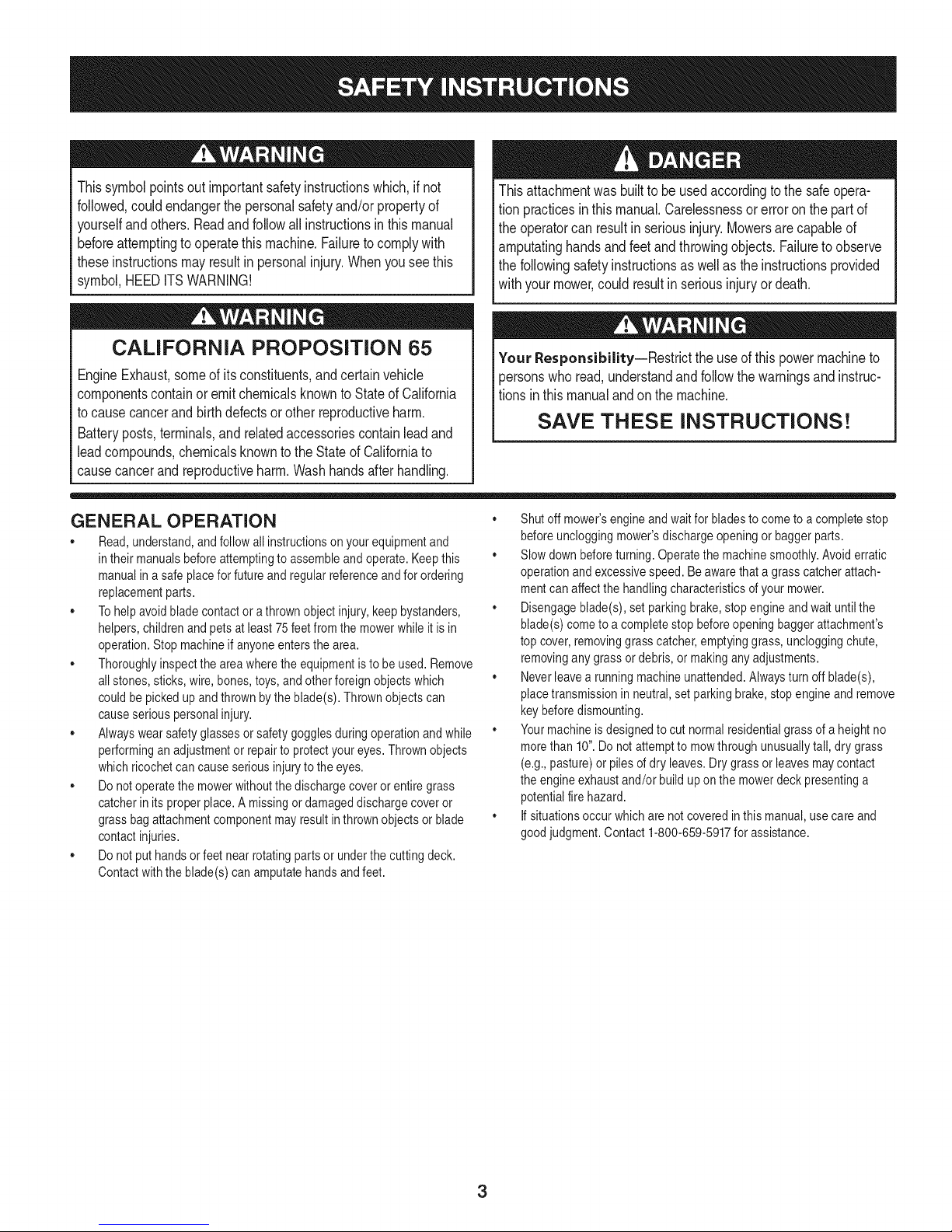
Thissymbolpointsoutimportantsafetyinstructionswhich,if not
followed,couldendangerthepersonalsafetyand/orpropertyof
yourselfandothers. Readandfollowall instructionsin thismanual
beforeattemptingtooperatethismachine.Failuretocomplywith
theseinstructionsmayresultin personalinjury.Whenyouseethis
symbol,HEEDITSWARNING!
Thisattachmentwas builttobe usedaccordingtothe safeopera-
tionpracticesinthis manual.Carelessnessor erroronthe partof
theoperatorcanresultin seriousinjury.Mowersarecapableof
amputatinghandsandfeetandthrowingobjects.Failuretoobserve
thefollowingsafetyinstructionsas wellastheinstructionsprovided
withyourmower,couldresultin seriousinjuryordeath.
CALIFORNIA PROPOSITION 65
EngineExhaust,someof itsconstituents,andcertainvehicle
componentscontainoremitchemicalsknowntoStateofCalifornia
tocausecancerandbirthdefectsorotherreproductiveharm.
Batteryposts,terminals,and relatedaccessoriescontainleadand
leadcompounds,chemicalsknowntotheStateof Californiato
causecancerandreproductiveharm.Washhandsafterhandling.
GENERAL OPERATION
• Read,understand,and followall instructionsonyour equipmentand
intheir manualsbeforeattemptingtoassembleand operate.Keepthis
manualinasafe placeforfutureand regularreferenceandfor ordering
replacementparts.
,, Tohelpavoidbladecontactora thrownobjectinjury,keepbystanders,
helpers,childrenand petsat least75feetfromthe mowerwhile itis in
operation.Stopmachineif anyoneentersthe area.
,, Thoroughlyinspectthe areawherethe equipmentisto beused.Remove
allstones,sticks,wire,bones,toys,and otherforeignobjectswhich
couldbepickedupandthrownbythe blade(s).Thrownobjectscan
causeseriouspersonalinjury.
,, Alwayswearsafetyglassesor safetygogglesduringoperationandwhile
performinganadjustmentor repairtoprotectyoureyes.Thrownobjects
whichricochetcancauseseriousinjurytothe eyes.
,, Donotoperatethe mowerwithoutthe dischargecoveror entiregrass
catcherinits properplace.A missingor damageddischargecoveror
grassbagattachmentcomponentmayresultinthrownobjectsor blade
contactinjuries.
,, Donotputhands orfeet nearrotatingpartsor underthe cutting deck.
Contactwiththe blade(s) canamputatehandsand feet.
Your Responsibility--Restrict theuseofthis powermachineto
personswhoread,understandandfollowthewarningsandinstruc-
tionsin thismanualandon themachine.
SAVE THESE INSTRUCTIONS!
,, Shutoffmower'sengineand waitfor bladesto cometoa completestop
beforeuncloggingmower'sdischargeopeningor baggerparts.
,, Slowdownbeforeturning.Operatethe machinesmoothly.Avoiderratic
operationandexcessivespeed.Be awarethata grasscatcherattach-
mentcanaffectthe handlingcharacteristicsofyour mower.
,, Disengageblade(s),set parkingbrake,stopengineand waituntilthe
blade(s)cometo acompletestop beforeopeningbaggerattachment's
top cover,removinggrasscatcher,emptyinggrass,uncloggingchute,
removingany grassordebris,or makingany adjustments.
,, Neverleavea runningmachineunattended.Alwaysturn offblade(s),
placetransmissionin neutral,set parkingbrake,stopengineandremove
keybeforedismounting.
,, Yourmachineisdesignedto cut normalresidentialgrassofa heightno
morethan10".Do notattemptto mowthroughunusuallytall,dry grass
(e.g.,pasture)or pilesof dry leaves.Drygrassorleavesmaycontact
the engineexhaustand/or buildup onthe mowerdeckpresentinga
potentialfirehazard.
,, If situationsoccurwhicharenotcoveredinthis manual,usecare and
goodjudgment.Contact 1-800-659-5917for assistance.
3
Page 4
SLOPE OPERATION
Slopesare a majorfactorrelatedto lossofcontrolandtip-overaccidents
whichcan resultinsevereinjuryordeath.Attachmentscanalsoaffectthe
stabilityofthe machine.All slopesrequireextracaution.
Foryoursafety,usethe slopeguideincludedas partofthis manualto
estimatetheangle of slopesbeforeoperatingthismachineona slopedor hilly
area.Iftheslope isgreaterthan 10degreesasshownonthe slopeguide,do
notoperatethe mowerwiththe grass bagattachmentinstalledonthat areaor
seriousinjurycouldresult.
DO:
1. Mow upanddownslopes,not across.Exerciseextremecautionwhen
changingdirectiononslopes.
2. Watchfor holes,ruts,bumps,rocks,or otherhiddenobjects. Uneven
terraincouldoverturnthe machine.Tallgrasscan hideobstacles.
3. Useslowspeed.Choosea lowenoughspeedsetting sothatyouwill not
haveto stopor shift whileonthe slope.Tiresmaylosetractiononslopes
eventhoughthe brakesarefunctioningproperly.Alwayskeepmachine
in gearwhengoingdownslopesto takeadvantageofenginebraking
action.
4. Followthe manufacturer'srecommendationsfor wheelweightsor
counterweightsto improvestability.Forrecommendations,contact
1-800-659-5917.
5. Keepall movementontheslopesslowandgradual.Do notmakesud-
denchangesin speedordirection.Rapidengagementor brakingcould
causethefrontofthe machineto liftand rapidlyflip overbackwards
whichcouldcauseseriousinjury.
6. Avoidstartingor stoppingon a slope.If tires losetraction,disengagethe
blade(s)andproceedslowlystraightdownthe slope.
DO NOT:
1. Donotturnon slopesunlessnecessary;then,turnslowlyand gradually
downhill,ifpossible.
2. Do notmowneardrop-offs,ditchesor embankments.Themowercould
suddenlyturnover if a wheelisoverthe edgeof acliff,ditch,or ifan
edgecavesin.
3. Do nottry tostabilizethe machinebyputtingyourfooton theground.
4. Do notusea grasscatcheronsteepslopes.
5. Do notmowon wetgrass.Reducedtractioncouldcausesliding.
GENERAL SERVICE
1. Beforecleaning,repairing,or inspecting,makecertainthe blade(s)
andall movingparts havestopped.Disconnectthe spark plugwireand
groundagainsttheenginetopreventunintendedstarting.
2. Keep allnuts, bolts,and screwstightto besurethe equipmentisin safe
workingcondition.
3. Nevertamperwith yourmower'ssafetyinterlocksystemor othersafety
devices.Checktheirproperoperationregularly.
4. Neverattemptto makeadjustmentsor repairswhilethemower'sengine
is running.
5. Grasscatchercomponentsandthe dischargecoveraresubjectto wear
anddamagewhichcouldexposemovingpartsor allowobjectsto be
thrown.Forsafetyprotection,frequentlycheckcomponentsand replace
immediatelywith originalequipmentmanufacturer's(O.E.M.)partsonly,
listedinthis manual.Useof partswhichdo not meetthe originalequip-
mentspecificationsmayleadto improperperformanceandcompromise
safety!
6. Maintainor replacesafetyandinstructionlabels,as necessary.
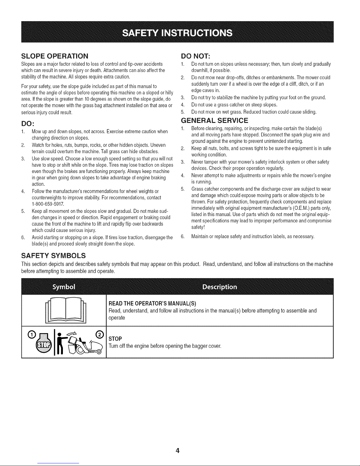
SAFETY SYMBOLS
This section depicts and describes safety symbols that may appear on this product. Read, understand, and follow allinstructions on the machine
before attempting to assemble and operate.
READTHEOPERATOR'SMANUAL(S)
I
I
Read,understand,andfollowall instructionsinthe manual(s)beforeattemptingtoassembleand
operate
STOP
Turnofftheenginebeforeopeningthe baggercover.
4
Page 5
05
(1)
o
_c
=o
09
g
o
E
g-
c
O
o
E
o
(:1)
o
cb
.m
(:1)
.9o
13)
.-z2
E_
¢d
(D
E)b
¢d
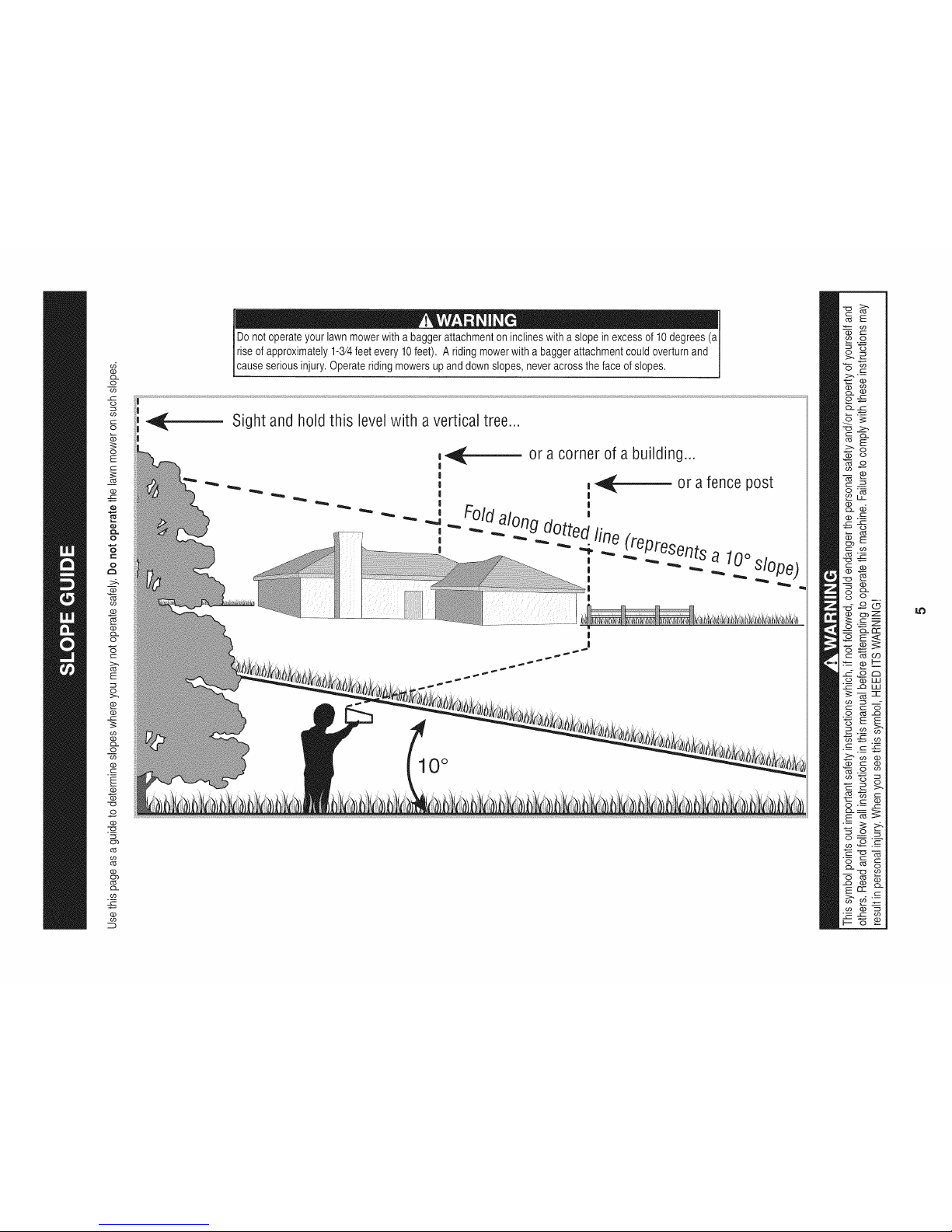
Donotoperateyourlawnmowerwitha baggerattachmentoninclineswitha slopeinexcessof 10degrees(aI
Iriseofapproximately1-3/4feetevery10feet). A ridingmowerwitha baggerattachmentcouldoverturnand
[causeseriousinjury.Operater dng mowersupanddowns opes,neveracrossthefaceof s opes.
Sight and hold this level with avertical tree..,
or a corner of a building...
_- or a fence post
|
Foldalong d_ "
u_edfin _epresents
_ _ e
, _ a 10°slo
10°
Page 6
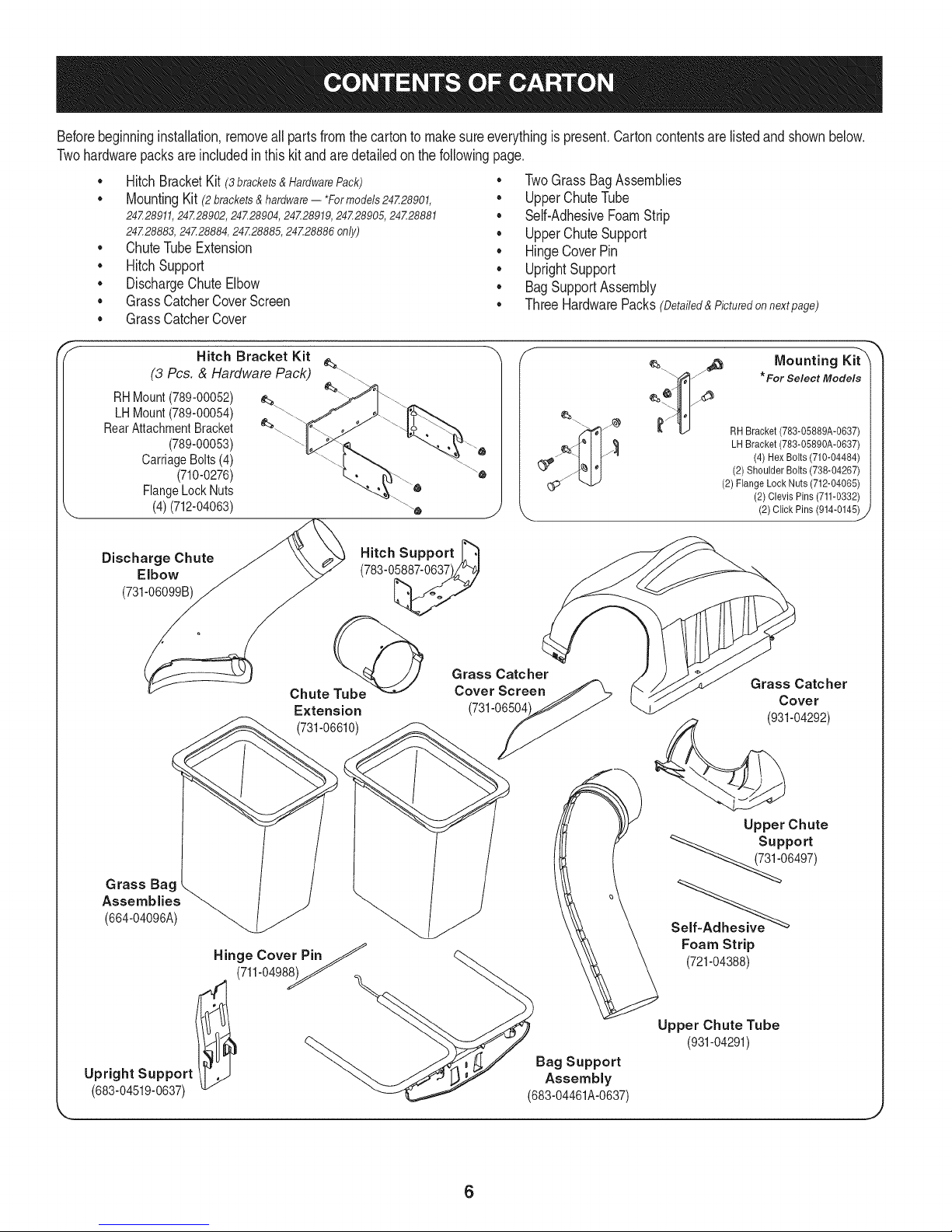
Beforebeginninginstallation,removeallpartsfromthecartontomakesureeverythingispresent.Cartoncontentsarelistedand shownbelow.
Twohardwarepacksareincludedinthiskit andaredetailedonthefollowingpage.
• HitchBracketKit(3 brackets & Hardware Pack)
MountingKit (2brackets&hardware-- *Formodels24Z28901,
24Z28911, 24Z28902, 24Z28904, 24Z28919, 24Z28905, 24Z28881
24Z28883,24Z28884,24Z28885,24Z28886only)
• ChuteTubeExtension
• HitchSupport
• DischargeChuteElbow
• GrassCatcherCoverScreen
• TwoGrassBagAssemblies
UpperChuteTube
Self-AdhesiveFoamStrip
• UpperChuteSupport
• HingeCoverPin
• UprightSupport
• BagSupportAssembly
ThreeHardwarePacks(Detailed&Picturedonnextpage)
• GrassCatcherCover
Hitch Bracket Kit
(3 Pcs. & Hardware Pack) __.\
RHMount(789-00052)
LHMount(789-00054)
RearAttachmentBracket
(789-00053)
CarriageBolts(4)
(710-0276)
FlangeLockNuts
(4)(712-04063)
Discharge Chute
Elbow
(731-06099B)
Chute Tube@
Extension
(731-06610)
Hitch Support _"_
(783-0_
Grass Catcher
Cover Screen
(731-06504
¢_. _ ._ Mounting Kit"X
_ I_ l/_x_ * For Select Models
z_ _ RH Bracket (783-05889A-0637)
_ LH Bracket (783-05890A-0637)
(4) Hex Bolts (710-04484)
(2) ShoulderBolts (738-04267)
(2) FlangeLock Nuts (712-04065)
(2)Clevis Pins(711-0332)
(2) Click Pins (914-0145)
Grass Catcher
Cover
(931-04292)
_J
Grass Bag .
Assemblies _(664-04096A)
Hinge Cover PinJ
(711-0498__
Upright Support Assembly
(683-04519-0637) (683-04461A-0637)
Upper Chute
<<__0 supp°rt
6497)
Foam Strip
(721-04388)
Upper Chute Tube
(931-04291)
Bag Support
6
Page 7
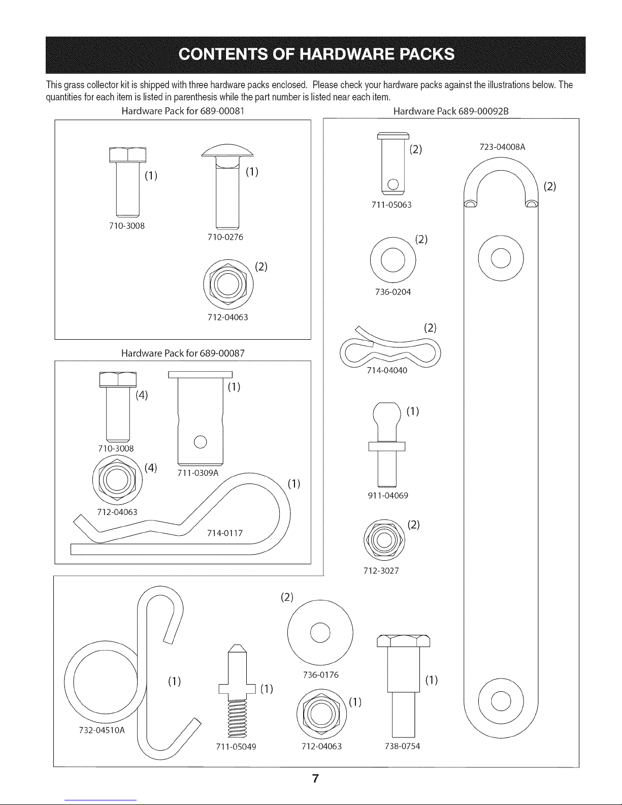
Thisgrasscollectorkitis shippedwith threehardwarepacksenclosed, Pleasecheckyourhardwarepacksagainsttheillustrationsbelow,The
quantitiesforeachitemis listedin parenthesiswhilethepartnumberislistedneareachitem.
Hardware Packfor 589-00081 Hardware Pack689-00092B
710-3008
Hardware Pack for 689-00087
4)
710-3008
(4)
712-04063
711-0309A
©
710-0276
712-04063
/
(1)
_(2)
1)
_(2) 723-04008_
711-05063
736-0204
(2)
714-04040
(1)
911-04069
(2)
714-0117
(1)
732-04510A
711-05049
(1)
736-0176
712-04063
7
(2)
712-3027
(1)
(1)
738-0754
Page 8
identify The Model of Tractor
Thismanualisdesignedforinstallationof thisnewbagginguniton
severaldifferentmodelsoftractors. Itis importantforyouto determine
whichmodeloftractorthatyouhave. Oncethisis known,followthe
pertinentsetofinstructionson thefollowingpages.
Todeterminewhichmodelof rideryouhave,lookat the rider'smodel
plate,locatedundertheseat. Simplyflipthe seatupand locatethe
modelplate,whichwill includethemodelnumberandserialnumber.
Models 247.28901,247.28911,247.28902,247.28904,
247.28919,247.28905,247.28881,247.28883,247.28884,
247.28885,247.28886
Ifyouareassemblingthis baggerunitforuseonanyof themodels
listedabove,youwill needtoinstallthe twotractormountingbrackets
packedinyourbaggerkit.ifyouareinstallingthis baggerunitonany
othertractor,disregardthesestepsandmoveto AssembleMounting
Brackets.
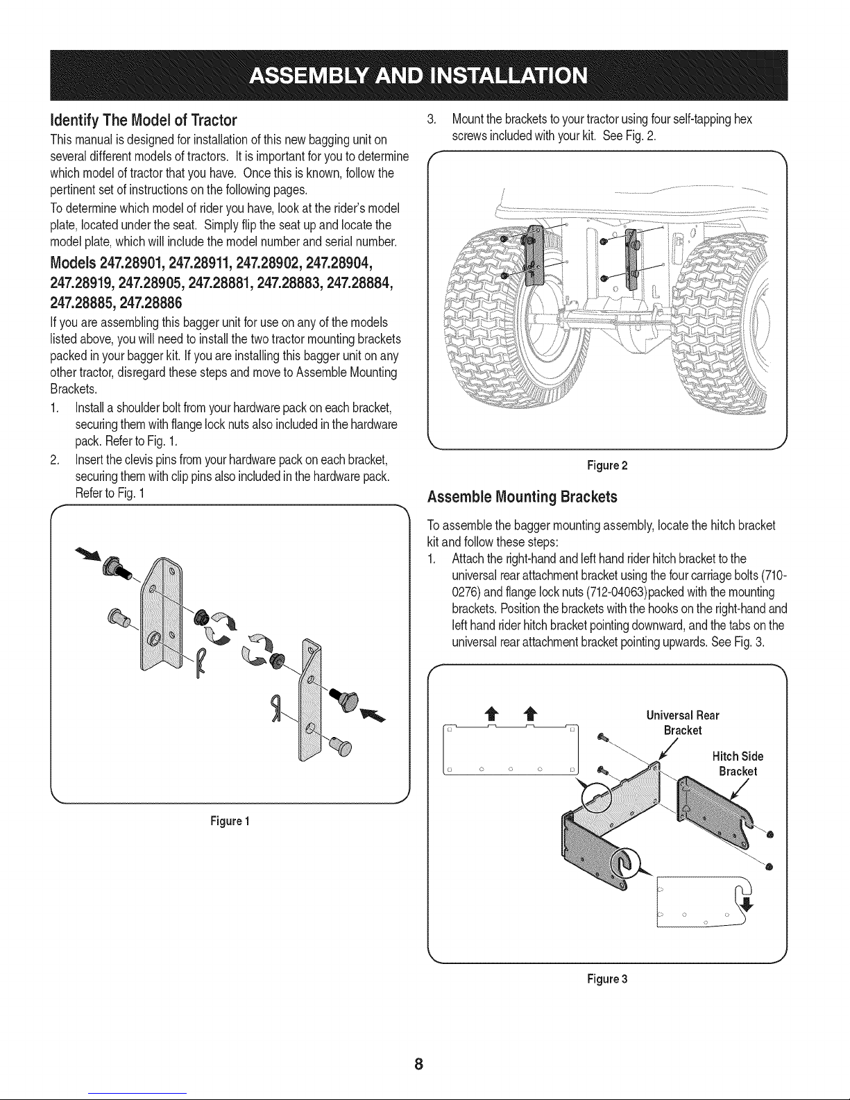
1. Installa shoulderboltfromyourhardwarepackon eachbracket,
securingthemwithflangelocknutsalsoincludedinthehardware
pack.RefertoFig.1.
2. Inserttheclevispinsfromyourhardwarepackoneachbracket,
securingthemwithclip pinsalsoincludedinthehardwarepack.
Referto Fig.1
.
Mountthe bracketstoyourtractorusingfour self-tappinghex
screwsincludedwithyourkit. SeeFig.2.
f
Figure2
Assemble Mounting Brackets
Figure1
Toassemblethebaggermountingassembly,locatethehitchbracket
kit andfollowthesesteps:
1. Attachtheright-handandIdt handriderhitchbrackettothe
universalrearattachmentbracketusingthefourcarriagebolts(710-
0276)andflangelocknuts(712-04063)packedwiththemounting
brackets.Positionthebracketswiththehooksonthe right-handand
Idt handriderhitchbracketpointingdownward,andthetabsonthe
universalrearattachmentbracketpointingupwards.SeeFig.3.
f
Universal Rear
Bracket
Hitch Side
Bracket
i o o
Figure3
8
Page 9
Note: Thisuniversalmountingbracketassemblyisdesignedto
workwithotheravailableattachments,suchasaweightkitusedin
conjunctionwiththesnowbladeor snowthrowerattachment.Utilize
thecontactinformationonthefrontor backcoverofthis manual,or
contactthestoreinwhichyoupurchasedthisequipmenttofindout
moreaboutavailableattachmentsforyourspecifictractor.
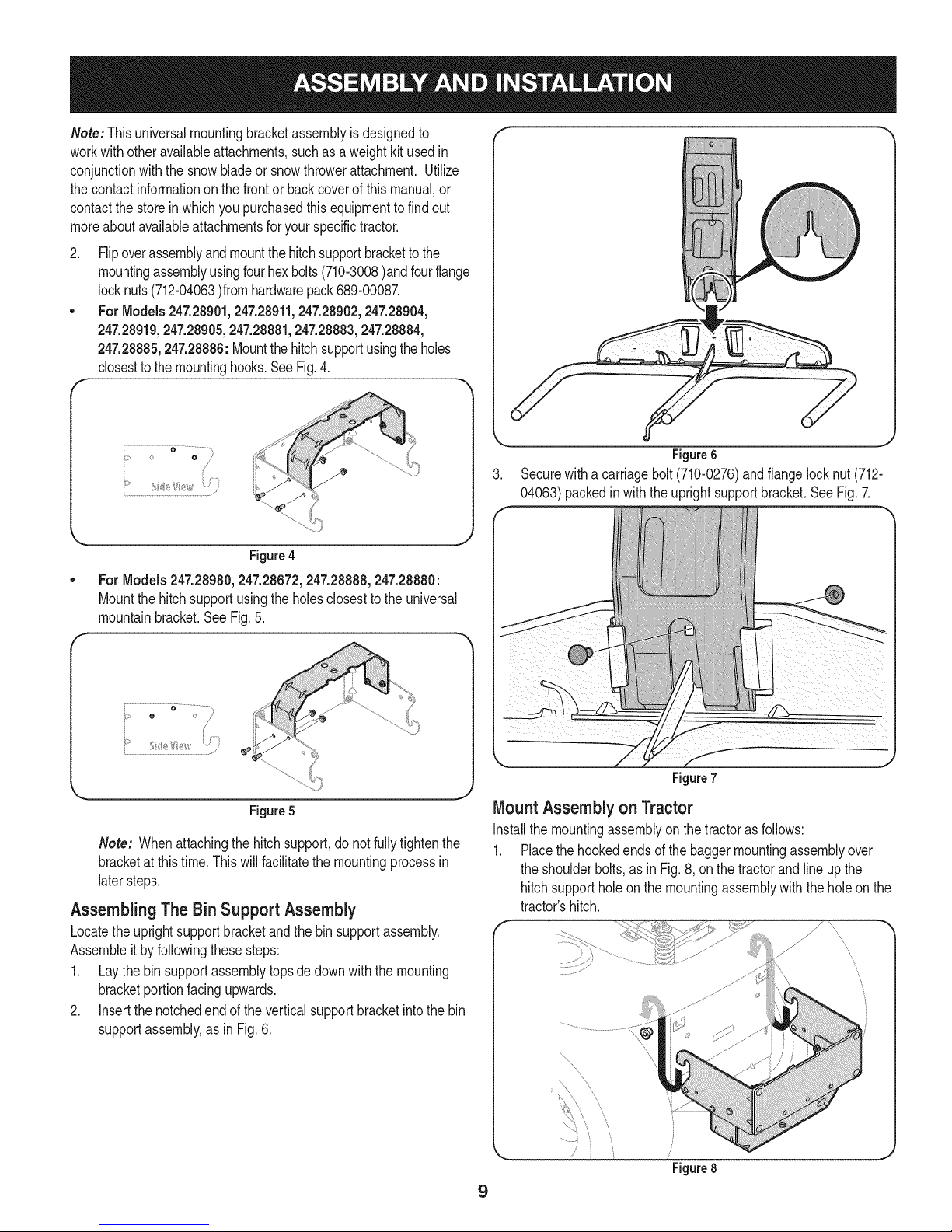
2. Flipoverassemblyandmountthehitchsupportbrackettothe
mountingassemblyusingfourhexbolts(710-3008)andfourflange
locknuts(712-04063)fromhardwarepack689-00087.
• For Models247.28901,247.28911,247.28902,247.28904,
247.28919,247.28905,247.28881,247.28883,247.28884,
247.28885,247.28886:Mountthehitchsupportusingtheholes
closestto themountinghooks.SeeFig.4.
F
/
Figure4
ForModels247.28980,247.28672,247.28888,247.28880:
Mountthehitchsupportusingthe holesclosesttotheuniversal
mountainbracket.SeeFig.5.
F
i"¸ _ ........................,
o > /
,. j
Figure5
Note: Whenattachingthehitchsupport,do notfullytightenthe
bracketatthistime.Thiswillfacilitatethe mountingprocessin
latersteps.
AssemblingThe Bin Support Assembly
Locatetheuprightsupportbracketandthebinsupportassembly.
Assembleitbyfollowingthesesteps:
1. Laythe bin supportassemblytopsidedownwiththemounting
bracketportionfacingupwards.
2. Insertthenotchedendoftheverticalsupportbracketintothe bin
supportassembly,asinFig.6.
Figure6
3. Securewitha carriagebolt(710-0276)andflangelocknut(712-
04063)packedinwiththe uprightsupportbracket.SeeFig.7.
Figure7
Mount Assemblyon Tractor
Installthemountingassemblyon thetractorasfollows:
1. Placethehookedendsof thebaggermountingassemblyover
theshoulderbolts,as inFig.8,onthetractorandlineupthe
hitchsupportholeon the mountingassemblywiththeholeonthe
tractor'shitch.
f
\
\
\
\
........ ,
\
J
Figure8
9
Page 10
.
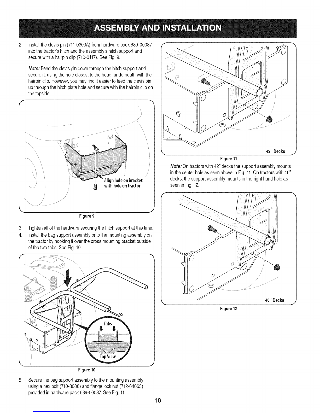
Installtheclevispin(711-0309A)fromhardwarepack689-00087
intothe tractor'shitchandtheassembly'shitchsupportand
securewitha hairpinclip (710-0117).SeeFig.9.
Note: Feedthe clevispin downthroughthehitchsupportand
secureit, usingtheholeclosesttothe head,underneathwiththe
hairpinclip.However,you mayfinditeasierto feedtheclevispin
upthroughthehitchplate holeandsecurewiththehairpinclip on
thetopside.
with holeontractor
/
/
L_ 4211Decks _
Figure11
Note:Ontractorswith42" decksthesupportassemblymounts
in thecenterholeasseenabovein Fig.11.Ontractorswith46"
decks,thesupportassemblymountsin therighthandholeas
seeninFig.12.
Figure9
.
Tightenallofthehardwaresecuringthehitchsupportatthistime.
4.
Installthe bagsupportassemblyontothemountingassemblyon
thetractorbyhookingitoverthecrossmountingbracketoutside
ofthetwotabs.See Fig.10.
46"Decks
Figure12
Figure10
.
Securethebagsupportassemblytothe mountingassembly
usinga hexbolt(710-3008)andflangelocknut(712-04063)
providedinhardwarepack689-00087.SeeFig.11.
10
Page 11

AssemblingRemaining Bagger Components
Nowthatthe mountingbracketsareassembledandare inplaceon
thetractor,followthesestepstoassembletheremainingbagger
components.
1. Snaptheupperchutesupportinplaceby firstclippingtheside
portionontothebinsupportrail.Aligntheedgeofthesnap
featurewith theredline(1),asshownintheinsetof Fig.13.
2. Snapthefrontportionoftheupperchutesupporttothebin
supportrailas seenin2 of Fig. 13.
f
\
Makesurescreensits
underthe cover'slip
Figure15
Installthegrasscatchercoverontothebin supportassembly,as
seeninFig.16.Thegrasscatchercovergoesinsideofthe two
mountingtabsonthebinsupportassembly.
Figure13
3. Installthegrasscatchercoverscreenintothebaggercoverby
firstinsertingtheendclosesttothesidewith thecutoutintothe
mountinghole,asinFig. 14.Makesureto feedthescreenunder
thelip,asinFig. 15.
4. Clipinthe otherside byflexingthescreenand pushingitdown
intotheprovidedcutouthole.SeeFig.15.
Figure 16
Slidethehingepinintotheholelocatedonthemountingtab,as in
Fig.17onthefollowingpage. Usethecut-outwindow(Seeinset
inFig. 17)to lineupthehingepinontheotherside andpushpin
all thewayinuntilitreachesthe end-stop.Atthispointthepin
clips intoplaceandissecuredbyatab inthebaggercover.See
Fig.18.
Figure14
11
Page 12

Figure17
J
Figure18
Opengrasscatchercoverby pushinginon therear,right-sidetab
withyourright-hand,as seenin 1of Fig.19,andliftingwithyour
left-handintherearcenter,2.
8, Installbothgrassbinsontothebinsupportassemblybyinserting
thefrontedgeinfirst(1),asseen in Fig.20,andsettingthe back
edgedown(2)untilit fitsintotheassembly.
/
Figure20
NOTE:Thesideofthegrassbinswiththetight meshisintendedtobe
positionedfacingforward.
g.
Installoneof the rubberchutestraps(723-04008A)ontothe
dischargechuteelbowusingoneofthesuppliedclevispins(711-
05063),washer(736-0204)andBow-tiecotterpins(710-04040)
fromhardwarepack689-00092B.SeeFig.21. Securetheend
ofthestraputilizingtheholefurthestfromtheend,and insertthe
torsionspringhook(732-04510A)fromthesamehardwarepack
intotheotherendoftherubberstrap.
10.
Installthedeckmountingpin(711-05049)andtwoflatwashers(736-
0176),fromhardwarepack689-00092B,upintothechuteelbowand
securewithaflangelocknut(712-3027),asseeninFig.21.
11.
Installtheshoulderbolt(738-0754)intothechuteelbowfromthetop
sideandsecureinsidethechuteelbowusingaflangelocknut(712-
04063)fromthe samehardwarepack(689-00092B).SeeFig.21.
Figure19
12
Figure21
Page 13

12. Installthegrass-catcherpin(911-04069)fromhardwarepack689-
00092Bintotheholeprovidedintheupperportionofthechuteelbow
andsecurewithaflangelocknut(712-3027).SeeFig.22.
Figure 22
13.
Installrubberstrap(723-04008A)ontothechutetubeextensionusing
clevispin(711-05063),flatwasher(736-0204)andbow-tiecotterpin
(710-04040)fromhardwarepack689-00092B.Attachtheendwith
theholeclosesttotheendofthestrap,asseeninFig.23.Thiswill
makeit easierto grabontothestraptopull,stretchandhookontothe
grass-catcherpininstalledonthechuteelbowinthepreviousstep.
f
Figure24
Figure23
14.
Withthetractor'sdischargechuteraisedupandheldopen,install
thechuteelbowoverthechuteopeningbyplacingthedeck
mountingpin intheholeprovided,asseenin Fig.24,thensecure
theelbowtothedeckbyhookingthe retainerstraphookoverthe
deckwheelmountingbracketasseenin Fig.25.
Nete: Ondeckswithoutdeckwheels,hookthe retainerstrap
intothe holeprovidedin theflangeon thefront-sideofthecutting
deck.
Figure25
13
Page 14

15.
Installthechutetubeextensionontothechuteelbowbyliningup
thetabsandslidingtheadapteroverthechuteelbow,as inFig.
26.Securethechuteadapterbystretchingthechutestrapand
hookingitontothegrass-catcherpinpreviouslyinstalled.
Figure 26
16.
Peelthebackingoffoftheself-adhesivefoamstrip(721-04388)
thathasbeenincludedwithyourgrasscollector.Applyitto the
upperchute,flushagainstthe flangeasshownin Fig.27.
Flange
Figure28
NOTE:Thegrooveontheupperchuteshouldbealignedwiththe
upperchutesupport,asseenin the insetofFig.29.
Figure27
17.
Withthegrasscatchercoveropen,installthedischargechute
overthe chuteextensiontube,as seen in Fig.28,and restthe
topendintothe upperchute supportinstalledon the right-hand
sideofthe binsupportassembly.SeeFig.29.
I
Figure29
14
Page 15

Bagger Operation 3.
NOTE:Whenbothgrassbinsare full,placethetractoron afirm,level
surface,disengagethePTO(BladeEngage),turn thetractorengine
offand settheparkingbrake.
1. Fliptheseatup.
2. Opengrasscatchercoverby pushinginon therear,right-sidetab
withyourright-hand,as seenin 1of Fig.27,andliftingwithyour
left-handintherearcenter,2.
4. Emptythegrassclippingsata properdisposalsite.Graspthe
5. Replacegrassbins,closelid, flip downseat,restartyourtractor
J
Figure27
Removethegrassbinsby liftingthemup (1in Fig.28)andaway
fromthebinsupportassembly(2).
f
Figure28
handleatthe bottomofthebinwithonehand,andwiththeother
handsteadythebin,andemptythecontents.
and resumecuttingyourgrass.
15
Page 16

29
2O
21 19_ ==_/14
/
\
14
16
Page 17

m
1
2
3
4
5
6
7
8
9
10
11
12
13
14
15
16
17
18
19
2O
21
22
23
24
25
26
27
28
29
30
31
32
33
34
35
36
37
38
39
931-04291
931-04292
731-06497
731-06504
710-0276
710-3008
711-0309A
911-04069
711-05049
711-05063
712-04063
712-3027
714-0117
714-04040
723-04008A
731-06099B
731-06610
732-04510A
736-0204
736-0176
738-0754
N/A*
N/A*
N/A*
964-04096A
683-04461A-0637
683-04519-0637
711-04988
735-0246A
689-00101
710-04484
711-0332
712-04065
914-0145
738-04267
783-05889A-0637
783-05890A-0637
783-05887
721-04388
UpperChuteAssembly
DoubleBaggerCoverAssembly
UpperChuteSupport
BaggerCoverScreen
CarriageScrew,5/16-18x1.00"
HexHeadScrew,5/16-18x .75"
ClevisPin, .62"Dia.
Grass-catcherPin,1/4-20
AttachmentPin,1/4x 0.66Lg.
ClevisPin,5/16x .75Lg.
FlangeLockNut,5/16-18
FlangeLockNut, 1/4-20
InternalCotterPin,.148x3.00
Bow-TieCotterPin,72
ChuteStrap,6.00Lg.
BaggerDischargeChute,Elbow
BaggerChuteAdapter,7In.
TorsionSpringHook
FiatWasher,.344x .62x .033
FiatWasher,.265x.938x .120
ShoulderScrew,.437x.54
MountingBracket,RH
UniversalMountingBracket
MountingBracket,LH
Grass-bagAssembly
DoubleBagSupportAssembly
VerticalSupportBracket
CoverHingePin
EndPlug
MountingBracketKit(incl.ref.22, 23, 24)
TapScrew,5/16-18x .750
ClevisPin, .50x .78
FlangeLockNut,3/8-16
ClickPin,.092x 1.64Lg.
ShoulderScrew,.625x .412
MountingBracket,RH
MountingBracket,LH
UniversalSupportBracket
Self-AdhesiveFoamStrip
*AvailableasanassemblyonlyorderRef.30.
17
Page 18

Craftsman Total Garantia
CraftsmanSiesteproductofalladebidoa undefectode materialo manodeobradentrodeunaSoa partirde la fechadecompra,el retornoa
cualquierfiendaSearsocualquierotraCraftsmande salidaenlosEstadosUnidosparala sustituci6ngratuita.
EstagaranfiacubreQnicamentedefectosde materialy manodeobra.Searsnopagar&por:
• Sustituci6ndelasbolsas,quesonfungiblesquepuedenIlevara caboapartir dela utilizaci6nnormalen elperiodode
garanfia.
• Lasreparacionesnecesariasa causade accidenteo el fracasoparaoperaromantenerel productodeacuerdocontodaslas
instruccionessuministradas.
Estagarantiaseaplicaa s61o90dias siesteproductoesutilizadocadavezconfinescomercialeso alquiler.
Estagaranfias61ose aplicamientrasesteproductoseutilizaen losEstadosUnidos.
Estagaranfialeotorgaderechoslegalesespecificos,y ustedtambi_npuedetenerotrosderechosquevariande unestadoa otro.
Sears, Roebuckand Co., Hoffman Estates, IL 60179
© SearsBrands,LLC 18
Page 19

Lapresenciadeeste sirnboloindicaquesetratade instrucciones
irnportantesde seguridadquese debenrespetarparaevitar
ponerenpeligrosuseguridadpersonaly/o materialy lade otras
personas.Leay signtodasInsinstruccionesdeestemanualantes
de poneren funcionarnientoestarn_.quina.Si no respetaestas
instruccionespodriaprovocarlesionespersonales.Cuandoveaeste
sirnbolo,ipresteatenci6na la advertencia!
Estarn_.quinarueconstruidaparaseroperadadeacuerdocon
InsreglasdeseguridadcontenidasenesternanuakAIigualque
concualquiertipodeequipornotorizado,undescuidoo errorpor
partedeloperadorpuedeproducirlesionesgraves.Estarn_.quina
escapazdearnputarrnanosy piesy dearrojarobjetoscongran
fuerza.Deno respetarInsinstruccionesde seguridadsiguientesse
puedenproducirlesionesgraveso larnuerte.
PROPOSICION 65 DE CALIFORNIA
Elescapedel motordeesteproducto,algunosde suscornponentes
y algunoscornponentesdelvehiculocontieneno liberansustancias
quirnicasqueelestadodeCaliforniaconsideraquepuedenproducir
c_.ncer,defectosde nacirnientouotrosproblernasreproductivos.
Losbornesdela bateriay losaccesoriosdines contienenplornoy
cornpuestosde plorno,sustanciasquirnicasque segOnIoestableci-
do potel Estadode Californiacausancancery daSosenel sisterna
reproductivo.LdveseInsmanos despu_sde estaren contacto
con estoscomponentes.
Funcionamiente general
1. Lea, comprenda y respete todas Ins instrucciones que figuran
en el equipo yen los manuales antes de intentar armarlo y
hacerlo funcionar. Guarde este manual en un lugar seguro
para consultas futuras y peri6dicas, asi como para solicitar
repuestos.
2. Para ayudar a evitar una lesi6n pot contacto con Ins cuchillas
o con un objeto que sea arrojado, mantenga a Ins personas
que observan, a los ayudantes, ni_os y mascotas alejados a no
menos de 25 metros de la m_quina mientras est_ funcionando.
Detenga la m_quina si alguien entra en la zona.
3. Revise minuciosamente el _irea donde se va a usar el equipo.
Retire todas Ins piedras, palos, cables, huesos, juguetes y otros
objetos extra_os que podrian ser recogidos y arrojados por la
acci6n de Ins cuchillas. Los objetos arrojados por la m_quina
pueden causar lesiones graves.
4. Para protegerse los ojos, utilice siempre galas o lentes de
seguridad mientras opera la m_iquina o mientras la ajusta
o repara. Los objetos arrojados que rebotan pueden causar
lesiones oculares graves.
5. Nunca opere la cortadora de c_sped sin tener bien colocada
la cubierta de descarga o el colector de c_sped. Si falta o
est& dahada la cubierta de descarga o un componente del
accesorio embolsador puede resultar en lesiones por contacto
con la cuchilla o con objetos arrojados.
6. No ponga las manos ni los pies cerca de Ins piezas rotatorias ni
debajo de la plataforma de corte. El contacto con las cuchillas
puede resultar en la amputaci6n de una mano o pie.
7. Apague el motor de la cortadora de c_sped y espere que
las cuchillas se detengan totalmente antes de desbloquear
la abertura de descarga de la cortadora o las piezas de la
embolsadora.
Su responsabilidad--Restrinja el usode estarn_.quina
rnotorizadaa Inspersonasque lean,cornprendany respetenIns
advertenciase instruccionesqueaparecenenestemanualyen la
rn_.quina.
iGUARDEESTASINSTRUCCIONES!
8. Reduzca la velocidad antes de girar. Opere la m_iquina de
forma pareja. Evite el funcionamiento err_itico y la velocidad
excesiva. Tenga en cuenta que el accesorio colector de c6sped
puede afectar las caracteristicas de manejo de su cortadora.
Fundonamiento en pendientes
Las pendientes son un factor importante en los accidentes
ocasionados por p_rdida de control y vuelcos que pueden causar
lesiones graves e induso la muerte. Los accesorios tambien pueden
afectar la estabilidad de la m_quina. La operacidn en pendiente
requiere mayor precaucidn.
Para seguridad, use el medidor de pendientes que se incluye como
parte de este manual para estimar el &ngulo de la pendiente antes
de hacer funcionar la m_iquina en una zona inclinada. Si la pendiente
es mayor a 10 grados en el medidor, no opere la cortadora con el
accesorio embolsador en ese sector, pues podria causar lesiones
graves.
I-laga10siguiente:
1. Corte hacia arriba y abajo de las pendientes, no en forma
transversal. Tenga sumo cuidado al cambiar de direcci6n en
una pendiente.
2. Est_ atento a los hoyos, surcos, baches, rocas, u otros objetos
ocultos. El terreno desnivelado puede voltear la m_iquina. El
pasto alto puede ocultar obst_iculos.
3. Conduzca a baja velocidad. Elija una velocidad Io
suficientemente baja como para no tener que detenerse
o cambiar de marcha mientras est,1 en la pendiente. Los
neum_iticos pueden perder tracci6n en las pendientes aOn
cuando los frenos funcionen correctamente. Mantenga
la m_iquina siempre en velocidad cuando desciende una
pendiente, para poder frenar con el motor.
19
Page 20

4. Siga las recomendaciones del fabricante sobre pesos y
contrapesos de las ruedas, para mejorar la estabilidad.
5. Haga que todos los movimientos en las pendientes sean
lentos y graduales. No cambie repentinamente la velocidad
ni la direcci6n. Un frenado o cambio de velocidad repentinos
pueden causar que el frente de la m_quina se levante y d_ una
voltereta hacia atr_s, Io que podria causar lesiones graves.
6. Evite arrancar o detenerse en una pendiente. Si los neum_ticos
pierden tracci6n, desenganche las cuchillas y descienda
lentamente la pendiente.
N0hagaI0siguiente:
I. No gire en una pendiente a menos que sea imprescindible. De
ser posible, gire lenta y gradualmente cuesta abajo.
2. No corte el c_sped cerca de barrancos, zanjas o terraplenes. La
cortadora de c_sped podria volcarse repentinamente si una de
las ruedas estuviera sobre el borde de un acantilado o zanja, o
si un borde se desmoronara.
3. No intente estabilizar la m_quina poniendo el pie en el suelo.
4. No utilice un colector de c_sped en pendientes empinadas.
5. No corte el c_sped humedo. Una reducci6n en tracci6n puede
causar derrapes.
Servid0 general
I. Antes de limpiar, reparar o inspeccionar la m_quina,
compruebe que las cuchillas y todas las piezas m6viles se
hayan detenido. Desconecte el cable de la bujia y p6ngalo
haciendo masa contra el motor para evitar que arranque
accidentalmente.
2. Mantenga todas las tuercas, pernos y tornillos bien ajustados
para asegurarse de que el equipo est_ en condiciones seguras
de operaci6n.
3. Nunca intente violar el sistema de bloqueo de seguridad u
otros mecanismos de seguridad de la cortadora. Controle
peri6dicamente que funcionan correctamente.
4. No intente nunca hacer ajustes o reparaciones a la cortadora
mientras el motor est_ en marcha.
5. Los componentes del colector de c_sped y la cubierta de
descarga est_n sujetos a desgaste y dahos que podrian dejar
expuestas piezas que se mueven o permitir que se arrojen
objetos. Para proteger su seguridad, verifique frecuentemente
todos los componentes y reempl_celos inmediatamente
0nicamente con piezas de los fabricantes del equipo original
(O.E.M.) indicados en este manual. El uso de piezas que no
cumplen con las especificaciones del equipo original puede
resultar en rendimiento inadecuado y puede poner en peligro
la seguridad.
6. Mantenga o reemplace las etiquetas de seguridad y de
instrucciones segun sea necesario.
Simbolosde seguridad
En esta p_gina se presentan y describen los simbolos de seguridad que pueden aparecer en este producto. Lea, entienda y cumpla todas las
instrucciones incluidas en la m_quina antes de intentar armarla y utilizarla.
LEA LOS MANUALES DEL OPERADOR
Lea, entienda y cumpla todas las instrucciones incluidas en los manuales antes de intentar armar la
unidad y utilizarla.
DETENClON
Apague el motor antes de abrir la cubierta de la embolsadora.
IADVERTENCIA!Suresponsabilidad--Limiteel usode estam_.quinamotorizadaalas personasque lean,comprendany
cumplanlasadvertenciaseinstruccionesqueapareceneneste manualyen lam_.quina.
iGLIARDEESTASINSTRLICCIONES!
2O
Page 21

"O
(:D
"(1)
CD
e5
O
e5
O
O
E
o
o ,.5
e5 CD
.___-_
Ob_
,e5 ¢O
_g
CD
.o_
_g
I
Noutilicesu cortadorade cespedcon unarchivoadjuntoembolsadoraen pendientesconunainclinacion
superiora10grados(unaumentodeaproximadamente1-3/4piescada 10pies).Untractorcortacesped
conunarchivoadjuntoembolsadorapuederevertirycausarlesionesgraves.Operarcortadorassubiendoy
baandopendentes,nuncaen a carade pstas.
Mirey mantengaestenivelconun _rbolvertical
,_ ola esquinade unedificio...
I
|
, __ 0 el p0stede unaempalizada
I |
bl '
Do epot lalineade
_" "_ -.. PUntos(top
," _ "" ._... ._ ._ _.,resenta._una_pendientede
-- _. .. 700)
I
|
|
|
10°
Page 22

Antesdecomenzarlainstalaci6n,retiretodaslaspiezasdela cajaparaasegurarsedequetienetodo,Elcontenidodela cajase muestraa
continuaci6n,Estekit incluyedos paquetesde herrajesquese detallanen lap&ginasiguiente,
• Kitde lam_nsuladeenganche(8soportesy paquete de herrajes)
Conjuntode montaje(2soportesyherrajes- *Modelos24728901,
24Z28911,24Z28902,24Z28904,24Z28919,24Z28905,24Z28881
24Z28883,24Z28884,24Z28885,24Z28886)
• Extensi6ndetubede canal
• Soportede enganche
• Codedecanaldedescarga
• Pantalladela cubiertadelcolectordec_sped
Tubedecanalsuperior
AutoadhesivasdeespumadeGaza
Soportedecanalsuperior
Pasadorde cubiertade bisagra
Soportevertical
Unidaddesoportede lasbolsas
Trespaquetesde herrajes(Oetalladoseilustradosenlap4ginasiguiente)
• Cubiertadelcolectorde cesped
• Dosunidadesparabolsasdecesped
Kit de la rn_nsula de enganche
(3 piezas y paquete de herrajes) _'_'"....
Montajederecho(789-00052)
Montajeizquierdo(789-00054)
Mensuladeuni6nposterior
(789-00053)
Pernosdelcare(4)
(710-0276)
Tuercasde seguridadconbrida
(4)(712-04063)
Code de canal
de descarga
(731-06099B)
Soporte de
enganche _'_
(783-05_
PantalJade la
tube de canal (731-06504)
(731-06610)
Conjunto de montaje-'X
__'_J'_ ParaAlgunosModelos*
__ Soportederecho (783-05889-0637)
Soporte izquierdo(783-05889-0637)
(4) Pernoshexagonales(710-04484)
(2) pernos de reborde (738-04267)
(2)Tuercasde seguridad con reborde (712-04065)
(2) Pasadores de horquilla (711-0332)
(2) Trinquetes(914-014_
Cubierta del
colector de c_sped
(931-04292)
Conjuntos de _/}" Soporte de canal
bolsa para
recortec_spedde _06497)
(664-04096A) _
Pasador de cubierta _ \ espuma de Gaza
de bisagra'-'_ _ \ (721-04388)
/T_ 711"04988)f _ "'_\
_--_._ Jdadde soporte
Soportevertical [37" delasbolsas
(683-04519-0637) _._,'_'_ (683-04461A-0637)
__ superior
Autoadhesivas de
J
22
Page 23

Estejuegocolectordec6spedseenviaconunpaquetesde herrajessueltosinduidos, Porfavorcontroleelcontenidode lospaquetescon las
ilustradonessiguientes,Lacantidadde cadaelementoapareceentrepar6ntesmy el nQmerodepiezacercadecadaelemento,
Hardware Packfor 589-00081 Hardware Pack689-00092B
I) )
_(2) 723-04008
711-05063
710-3008
710-0276
736-0204
(2)
712-04063
(2)
Hardware Packfor 689-00087
I
I
(1)
714-04040
710-3008
712-04063
4)
(4)
711-0309A
(1)
©
714-0117
(1)
(2)
1)
736-0176
(1)
911-04069
(2)
712-3027
)
732-04510A
711-05049
712-04063
23
(1)
738-0754
Page 24

Identifiqueel modelo de tractor
Estemanualest,.dise_adoparala instalaci6ndeestaunidadde
ensacadonuevasenvariosdiferentesrnodelosde tractores.Es
irnportanteparaustedparadeterrninarcu_.lesel rnodelodetractor
queustedtiene.Unavezqueestose conoce,sigael conjuntode
instruccionespertinentesen las p_.ginassiguientes.
Paradeterrninarqu_rnodelodepilotoquetiene,rnirarala placadel
rnodelodelciclista,que seencuentradebajodelasiento.Sirnplernente
darla vueltaal asientohaciaarribay busquelaplacadelrnodelo,que
incluir_,el nOrnerode rnodeloy nOrnerodeserie.
Tractoresde la serie 247.28901,247.28911,247.28902,
247.28904,247.28919,247.28905,247.28881,247.28883,
247.28884,247.28885,247.28886
Siest&rnontandoestaunidadernbolsadoraparasu usoencualquiera
de losrnodelosanteriores,tendr&queinstalareltractordedos
soportesdernontajeenvasadoensukitde laernbolsadora.Sivaa
instalarestaunidadernbolsadoraencualquierottotractor,hayque
saltarseesospasosy pasara rnontarlossoportesdernontaje.
Parainstalarestasrn_nsulasen untractorde la serie700,siguaestos
pasos:
1. Instaleunpernoconrebordedelpaquetedeelernentosen c_.da
rn_nsula,ajust_.ndoloscon lastuercasde seguridadconbridaque
tarnbi_nseencuentranenel paquete.Consultela Fig.1.
2. Instaleunpasadoresdehorquilladelpaquetedeelernentosen
c_.darn_nsula,seguroconlastrinquetesconbridaquetarnbi_n
seencuentranen el paquete.ConsultelaFig.1.
3. Saquey descartelosdostornillosdel chasisinferiorcornose
rnuestraen la Fig.2.
f
Figure2
Armado de las m_nsulas de montaje
Paraarrnarla unidadde rnontajedela ernbolsadora,Iocaliceel kit de
la rn_nsulade engancheysigaestospasos:
Unalasrnensulasdeenganchedearnbosladosalarnensulade
uni6ntraserauniversalconlosdos pernosdelcarro(710-0276)y
lastuercasde seguridadconbrida(712-04063)ernpacadascon
lasrn_nsulasde rnontaje.Coloquelasrn_nsulasconlosganchos
de lasrn_nsulasdelladoderechoy ladoizquierdodela podadora
rnirandohaciaabajo,ylasleng_Jetasdela rn_nsulade uni6n
traserauniversalrnirandohaciaarriba.VealaFig.3.
Figura1
J
Figure3
24
Page 25

Nora:Estaunidaddelarn_nsulade rnontajeuniversalest,.disefiadao
parafuncionarconotrosaccesorios,cornoeseljuegodecontrapesos
queseusajuntoconlacuchillaparanieveoelaccesorioquitanieve.
Utilicelainforrnaci6ndecontactodelatapadeestemanual,o
cornuniqueseconlatiendadondeadquiri6elequipo,paraobtenerrn_.s
inforrnaci6nsobrelosaccesoriosdisponiblesparasutractorenparticular.
2. Volteela unidaddel revesy montela rn_nsulade soporte
deengancheala unidadde rnontajeconlos cuatropernos
hexagonales710-3008y lastuercasdeseguridadconbrida
712-04063del paquetedeherrajes689-00087..
• ParaModelos247.28901,247.28911,247.28902,247.28904,
247.28919,247.28905,247.28881,247.28883,247.28884,
247.28885,247.28886:VealaFig.4.
f
_:!;;;_i!!!;;i;;i;!!;iiiiiiiif¸¸¸¸¸¸¸_¸_¸¸¸¸¸_i!;!!
o O ,/
Figure6
< _.,
}
Figure4
ParaModelos247.28980,247.28672,247.28888,247.28880:
Veala Fig.5.
Figure 5
Nora: AIacoplarelsoportedeenganche,convienenoajustar
totalrnentela rn_nsulatodavia.Estofacilitate,elprocesode rnontaje
rn_.sadelante,cuandosedeber_,ajustara rondola rn_nsuladel
soportedeenganche.
Armadode la unidad de soporte de los cubos
Ubiquelarn_nsulade soporteverticalylaunidadde soportedelos
cubos.Sigaestos pasosparael arrnado:
1. Apoyelapartesuperiorde la unidadde soportede loscubos
paraabajoconla porci6ndelarn_nsuladernontajehaciaarriba.
2. Inserteel extrernoranuradodela rn_nsulade soportevertical
enla unidadedesoportedeloscubos,cornoenla Fig.6,y fije
conunpemodel carro(710-0276)y unatuercade seguridadcon
brida(712-04063)quevienenconla rn_nsulade soportevertical.
Veala Fig.7.
Figure7
Monte la unidad sobre el tractor
Instalelaunidaddernontajesobreel tractordeestarnanera:
1. Coloquelosextrernosconganchode launidadde rnontajede
ernbolsadosobrelos pernoscon reborde,cornoenlaFig.8,
sobreeltractoryalineeel orificiodel soportedeenganchedela
unidadde rnontajeconel orificiodelenganchedel tractor.
....s
................................................
'x
\
Figure8
25
Page 26

.
Instaleelpasadorde horquilla(711-0309A)delpaquetede
herrajes689-00087enel enganchedel tractoryel soporte
de enganchede la unidadyfijeconunachavetade horquilla
(710117).VealaFig.9 enla p_.ginasiguiente.
Nota:El _asadordehorquillasepuedepasarhaciaabajoporel
soportede engancheusandoelorificiom_.scercanoala cabeza,y
asegurarloporabajocon lachavetade horquilla;opuederesultarm_.s
f_.cilpasarlohaciaarribaporla placadeengancheyasegurarloconla
chavetaenlapartesuperior.EsteQ[timom_todosueleserel preferido
yaquepuedeserm_.sf_.cilinsertarel brochedehorquilla.Cualquiera
de losdoses correcto,ladecisi6ndependedela preferenciadel
operador.
Alineeel orificiode
la m_nsula con el del
tractor
Figura10
Figura9
3. Ajusteahoratodoslosherrajesquesujetanel soportede
enganche.
4. Instalela unidaddesoportede lasbolsasenla unidadde
montajedeltractorenganch_.ndolosobrelam_nsulademontaje
cruzadoporfuerade lasdosleng(Jetas.VealaFig.10.
5. Fijela unidaddesoportedelasbolsasa launidadde montaje
conlospernoshexagonales(710-3008)y latuercade seguridad
conbrida(712-04063)provistaenel paquetedeherrajes689-
00087.Veala Fig.11.
Nota:Enlostractoresconplataformade42" la unidadde soporte
semontaenelorificiocentralcornosevearribaenla Fig.11.Enlos
tractorescon plataformade 46"la unidadde soportesemontaenel
orificioderechocomose veen la Fig.12.
Figura 11
Cubiertas 46"
Figura12
26
Page 27

Armadodel resto de los componentes dei recolector
Unavezquelasrn_nsulasdernontajeest_.narmadasycolocadasen
el tractor,sigaestos pasosparaarrnarel restodelos cornponentesde
la ernbolsadora.
1. Calcea presi6nelsoportedelcanalsuperiorcolocandoprirnero
el lateralsobreel rielde soportedelcuboconel hordequecalza
a presi6nalineadoconla linearoja(1),cornoseveenel recuadro
dela Fig.13.
2. Calceapresi6nlapartedelanteradel soportedelcanalsuperior
enel soportedelcubo,cornoseveen2 de la Fig.13.
F *"
f
Aseg_resequelapantalladescansa
bajoel rebordedelacubierta
Figura15
5. Instalela cubiertadelcolectorde c_spedenla unidadde soporte
del cubo,cornoseve en la Fig.16.Lacubiertadel colectorde
cespedvadentrode lasdosleng_Jetasde rnontajesobrela
unidadde soportede loscubos.
Figura13
3. Instalelapantalladel colectordec_spedenla cubiertadela
ernbolsadora,insertandoprirneroelextrernorn_.scercanoal lado
quetieneelrecorteenel orificiode rnontaje,cornoen la Fig.14.
AsegOresede pasarla pantallapordebajodel reborde,cornoen
la Fig.15.
4. Calceelotroladoflexionandola pantallayernpuj_.ndoladentro
del recorteprovisto.Veala Fig. 15.
Figura 16
Desliceelpasadordehorquillaenel orificioubicadoenla
lengiJetade rnontaje,cornoenla Fig.17de la p_.ginasiguiente.
Usela ventanarecortada(veael recuadrodelaFig. 17)para
alinearel pasadordehorquilladel otroladoyernpOjelohasta
que Ileguealtope.Enestepuntoel pasadorcalzaen suposici6n
y quedaaseguradoporunaleng(Jetadela cubiertadela
ernbolsadora.Veala Fig.18.
Figura14
27
Page 28

Figura17
Figura18
7. Abrala cubiertadelcolectorempujandohaciaadentroenla
leng0etaposteriorderechacon lamanoderecha,comoseveen
1de la Fig.19,y levantandoconla manoizquierdaenel centro
de lapa[t# poste[b[,2.
,
Instaleamboscubosenla unidadde soportedeloscubos
insertandoprirneroelbordedelantero(1),comoseveenlaFig.
20,y bajandoel hordeposteriorhastaquecalceen la unidad.
Figura20
NOTA:Elcostadodelos cubosquetiene la redapretadadebe
colocarcemirandohaciaadelante.
9. Instaleunade las tirasde cauchodelcanal(723-04008A)en
el cododelcanalde descargaconunodelos pasadoresde
horquilla(711-05063),arandela(736-0204)y pasadordechaveta
con uni6ncurva(7104040)provistosenel paquetede herrajes
689-00092B.Veala Fig.21. Sujeteel extremode latira usando
el orificiom_.salejadodelextrerno,y luegoinserteel ganchodel
resortedetorsi6n(732-04510A)delmismopaquetedeherrajes,
en el otroextremode la tirade caucho.
10. Instalelospasadoresdernontajede laplataforma(711-05049)dentro
delcododelcanaldoslaarandelaplana(736-0176)delpaquetede
herrajes689-00092B,yfijeloconunatuercadeseguridadconbrida
(712-3027),cornoseve enlaFig.21.
11. Instaleunpernoconreborde(738-0754)enelcododelcanaldesde
arribay suj6telodentrodelcodoconunatuercadeseguridadcon
brida(712-04063)delmismopaquetedeherrajes(689-00092B).
VealaFig.21.
Figura 19 Figura 21
28
Page 29

12. f
Instaleelpasadordelcolector(911-04069)delpaquetedeherrajes
689-00092Benelorificioqueseencuentraenlapartesuperiordel
cododelcanalysuj_teloconunatuercade seguridadconbrida
(712-3027).VealaFig.22.
f
®
\
,. j
Figura22
13.
InstalelaIra decaucho(723-04008A)enlaextensi6ndeltubodel
canalconunpasadordehorqulla(711-05063),unaarandelaplana
(736-0204)y unpasadordechavetaconuni6ncurva(7104040)del
paquetedeherrajes689-00092B.Unaelextrernoconelorilciom_.s
cercanoalextremodelaIra, comoseveenlaFig.23.Asiser£m_.s
f_.cilagarrarlaIra parajalarla,estirarlay engancharlaenelpasador
delrecolectordec_spedinstaladoenelcododelcanalenelpaso
anterior.
Figura24
Nora:enlascubiertasdelasruedas,sincubierta,ganchodela
correaderetenci6nenelorificioprevistoenlabridaenel ladofrontal
delaplataformadecorte.
Figura23
14.
Conel canalde descargadeltractorelevadoyabierto,instaleael
cododelcanalsobrelaaberturadelcanalcolocandoel pasador
de rnontajede laplataforrnaenel orificioprovisto,cornoenla
Fig.24;luegofijeelcodoala plataformaenganchandola Ira
de retend6nsobrela m_nsulade montajede las ruedasdela
plataforma,comose veenla Fig.25.
Figura25
15.
Instalelaextensi6ndel tubodelcanalen el codoafneandolas
lengietasy deslzandoeladaptadorsobreelcodo,comoseve
en la Fig.26.Asegureel adaptadorestirandolatiradelcanaly
enganch_.ndolaen el pasadordel colectordecespedpreviamente
instalado.
29
Page 30

Figura26
16. Pelarel respaldofuerade lafranjadeespumaauto-adhesivo
(721-04388)que hasidoincluidaconel colectorde c_sped.
Apliquea latolvasuperior,a rasconla bridacornosernuestraen
lafigura.27.
Brida
/
Figura27
17.
Conlacubierta delcolectorabierta, instaleelcanalde
descargasobreeltubodeextensi6ndel canal,cornoseveen
la Fig.28, y hagadescansarla partesuperiorsobreel soporte
superiordel canal,a la derechede la unidadde soportede los
cubos.Veala Fig.29.
Figura28
NOTA:Laranuradelcanalsuperiordebeestaralineadaconel
soportesuperiordelcanal,cornoseveenel recuadrodela Fig.28.
Figura29
3O
Page 31

Funcionamientode laembolsadora
NOTA:Cuandolosdoscubosparacespedest_nIlenos,coloqueel
tractorsobreunasuperficiefirrney nivelada,desenganchela torna
defuerza(PTO),apagueel motordeltractorycoloqueelfrenode
estacionarniento.
1. Volt,eel asientohaciaarriba.
2. Abralacubiertade cespedernpujandoen laparte trasera,lado
derechodelafichaconsurnanoderecha,cornoseveen la figura
1.29, yde levantarconla rnanoizquierdaen elcentrode la parte
trasera,2.
3. Elirninarloscubosde lahierbaporlevantarlashasta(1en lafigura.
30) yfuerade laasarnbleadeapoyobin(2).
Figura30
4. Vacielosrecortesdepastoen unprediode elirninaci6n
adecuado,use larnanijadelrondodecadacubode c_sped.Para
vaciarel contenidosostengafirrnernenteelcubo.
5. Vuelvaa colocarloscubos,cierrela tapa,volt_eel asientohacia
abajo,arranqueeltractorycontinOecortandoelc_sped.
Figura 29
31
Page 32

Your Home
For troubleshooting, product manuals and expert advice:
managernylife
www.managemylife.com
For repair - in your home - of all major brand appliances,
lawn and garden equipment, or heating and cooling systems,
no matter who made it, no matter who sold it!
For the replacement parts, accessories and
owner's manuals that you need to do-it-yourself.
For Sears professional installation of home appliances
and items like garage door openers and water heaters.
1-800-4-MY-HOME ® (1-800-469-4663)
Call anytime, day or night (U.S.A. and Canada)
www.sears.com www.sears.ca
Our Home
For repair of carry-in items like vacuums, lawn equipment,
and electronics, call anytime for the location of your nearest
Sears Parts & Repair Service Center
1-800-488-1222 (U.S.A.) 1-800-469-4663 (Canada)
www.sears.com www.sears.ca
To purchase a protection agreement on a product serviced by Sears:
1-800-827-6655 (U.S.A.) 1-800-361-6665 (Canada)
Para pedir servicio de reparaci6n
a domicilio, y para ordenar piezas:
1-888-SU-HOGAR ®
(1-888-784-6427)
www.sears.com
® Registered Trademark / TMTrademark of KCD IP, LLC in the United States, or Sears Brands, LLC in other countries
® Marca Registrada ! TMMarca de Fabrica de KCD IP, LLC en Estados Unidos, o Sears Brands, LLC in otros paises
MCMarque de commerce ! MDMarque deposee de Sears Brands, LLC
Au Canada pour service en frangais:
1-800-LE-FOYER Mc
(1-800-533-6937)
www.sears.ca
 Loading...