

Page 1

Operator's Manual
CRRF
flll l * 'r
12 Amp
Electric
Lawn
Model No.
!72.79183
,.°!
[ |11_1]_
CAUTION:
Read,,P_terstandandfotlowall S_fety
RulesandOperatingInsOtlctionsinthis
Manualbeforeusingthispmduct_
Sears Bra_ds Management COrpomtlon,
Hoffman Estates, IL 60179 U.S.A.
www.oraftsman.c()m
• WARRANTY
_,_F_
A_;_r_MBLY
• MAINTENANGE
• PARRS LIST
Page 2

I
Warranty ............................................................................................ Page
Safety Symbols....................... ;.......................................................... _Page
Safety Instructions ................................. _......................... _..... _.............. Pages
Unpacking ............................................................ _.... _.................. .,._Page 10
Descriptim3.......................................................................................... Pages 11
Assembly and Adjustments.................................................................. Pages 13
Operation:......................................................................... ................. ...Pages 17
Mamtenance....................................... : .................................................. Pages 23
Parts List .............................................................................................. Pages 25
CRAFTSMAN TWO YEAR FULL WARRANTY
FORTWOYEARS from the date of purchase, this product is Warrantedagainst any
defects in material oTworkmanship.Defectiveproductwillbe replaced free of charge.
For w_Prantycoveragedetails Orto obtaFnfree replacement,
visit theweb'site; www.craftsman.com
This warranty does notcover the blade, whichis an expendable part that can wear
out from normal .usewithinthe warrantyperiod.
This war_'antyis void if thisproductis ever used while providing(/ommercialservices
or ifrented to another person.
This warranty givesyou specificlegal rights,and youmay also haveother rightS
whichvary from state to state.
Sears Brands ManagementCotporation, Hoffman Estates, fL 60179
2
3
4-9
-12
.22
- 24
- 27
/ contains chemicals known to. the State of California to cause cancer and birth '
Ii .__ WARNING: Some dust created by using lawn and garden power tools {
| def_N or ether reproductive harm. .........
SAVE THESE INSTRUCTIONS!
READ ALL INSTRUCTIONS i
Page 3

The purpose of safety symbolsis to attract your attentionto possible dangers.The
safety symbols,,andthe explanationswith them, dese_e your careful attention and
understanding. The symbolwarnings DO NOT by themse|ves eliminateany danger.
The ins_uctionsand warningsthey give are no substitutesfor proper accident
preventionmeasures.
manual, inoluding all safety alert symbols such aSr"DANGER", "WARNING" ' i
and "CAUTION", BEFORE using this toeL Failure to follow all Instructions listed !
I Z_ WARNING: BE SURE to read and understand all safety lns_ucU0nsln this I
below may result in electric shock, fire and/or serious persona! Injury. " t
SYMBOL MEANING
I /_. SAFETY:ALERT SYMBOL; IndicatesDANGER,WARNING, OR
t Z._ CAUTION. May be used in sonju,st[onwith0ther symbols or pictograpbs.
• I _ serious injuw to yourself or to others. Always follow _e .
t • safety precautions to reduce the risk of fire, electric shocK.
I .... and pers°nal ._jury" = .... •
obeythissaf, wami"0 suit,- d.tho;
I _: seriousinjury to yoUrselfor to ottiers. Always fallow the !
/ " safety precau.ti_ns to.reduce the risk of fire,'electri¢ Shock _ /
..... ..... !
I I, ..;'...". .I n_,y .u_.elt_.o_sori_eg._.:dam._, ._ays I
I ........ fo,ow.me s.a.fe.W-.pLr._.au._u=_s.-to_Iu_e the_k offire, I
I .• .. ,. .ele_Id_shock_._d,per_on'_!;inlu_, . I
DAMAGE.PREVENTION.ANDINFORMA'FION MESSAGES " "
.TheSe i_fermuser of important-informatiol_:a_.d/orl_stru_3ons that c_uidlead tO.
equipmer_torotherproperlydamage if rmtfollowed:E_ message is precededby the word-
" "NOTE:* as ie the examplebelow:
i.NOTE: Equipmentand/or propertydamage may result !_ffiese lnatruetlens .......I
I airsnot foUowed "
_-WARNtNG: Theoperatioa of any edgelr_ result In
foreign objects being t_rewn htte your eye=.,wl_hean
result in severe e_e dan_. e, Be:,_ beginning pewer te_l.
W. side s elds ar_!a full_a_e'sJdeidwhen needed; We
re.mineral a Wide Vlsl_ Safety Mask for.ule over
eyeglassas or standard safe_ glasses with-side shields,
available at Sears Sfo_,esOr_er craftsman Outlets,
. : : :: : : . : ....
Page 4

• . ,, ,, . . . ,
WARNING: if cOrrectly used, this electric Edger is an easy to handle and
efficient tool; if used improperlyor without the dueprecautions it could become a
dangerous toot. For pleasant and safe work, ALWAYSstrictly comply with the safety
rulesthat are contained in this manual. •
,,ILII =
Z_ WAR NING: BE SURE to read and understandall instructions in this manual, i
before using.this electric Edger. Failure-to follow all Instructions listed below may |
result _ electric shock, fire andlor seriouspersonal injury. 1
/IX WARNING: To avoid mistakes thatcould cause serious injury, DO NOT plug 1
in;this tool untilthe following instructionshave been mad and u_derst0od, I
WORK AREA SAFETY
1, ALWAYS avoid dangerous conditions. =DO NOT use in wet or damp: areas or
expose to. rain.
2. DO NOT operate in the presence of flammable liquids, gases, or dust. EleCtiiC"
toolscreate sparkswhich may ignitedustor fumes.
3. ALWAYS keep bystanders and visitors at a safe distance whileop_ratihg
an Edger. NEVER allow children near the tool.Flying objects can injure anyotie
inthe area,
4. CHILDPROOF your tools with padlocksand masterswitches. Lock toolsaway when
not in use. This Edger isn_ta toy.
5. DO NOT use the Edger withoutadequate lighting.=ALWAYS makesure thatyou can
see what you are edging.
6. BEFORE using the Edger, rembve anysto_es, sticks, debris or 0bjectSthat could
be entangted in orthrown by the Edger.
PERSONAL SAFETY
, " "" • " ,-i,, ,; .... ,:, -
i A_ WARNING: The operatibn of any Edger can result in FOREIGN OBJECTS 1
I BEING THROWN, which can result in personai injury or proPerty damage.
I ALWAYS use proper safety equipment,
1. KNOW your tool. Read the operator'smanual_arefully: Learnthe electricEdger's
applicationsand limitations,as Wellas the specificpotentialhazardsrelated tothistool.
2. STAYALERT, watchwhatyou are=doingand usecommonsense when operatingthistool.
3. DO NOT use tool while tired or undertheinfluenceof drugs,alcoholor medication.
A momentof inattentionwhileoperatingthistoolmayresult in serious personatinju_J.
4. DRESS properly. Wear rubberglovesandsubstantialrubbersoledfootwear when
workingoutdoors.DO NOT operate lawnand gardentobls when barefootor wearing
opensandals.Wear longpantsahd longsleevestoprotectyour legs and arms.
• Edgerscan pickup objectssuchas rocksand send them flyingat fast speeds.
DO NOT wear looseclothingorjewelry.Keep yourhair,Clothing,andglovesaway
form moving parts.[3ose clothingor tonghair can be caughtinmovingparts.
i
Page 5

PERSONALSAFETYconL
5. USESAFETYEQU!PMENT.Alwayswear safety gogglesor safetyglasses with side
shieldsor full face shield,proper work shoeswith rubbernon-slipsoles, heaYy-duty
non-sliprubber glovesand dust mask or respiratorand hearing protection.Hard
hat shouldbe used for appropriate conditions.
6; DO NOT overreach. Keep proper footing and balance at all times. Properfooting and
balance enables better controlof the tootinunexpectedsituations:
TOOL USE AND CARE SAFETY
I Z_ wARNING: BE SURE to mad and understand all: instructions before I
I operating this tool. Failure to follow all ins_uctions listed below may resuR in
I electric shock, fire and/or serious personal injury.
i. DO NOT usethe tool if switch does not turn it "On" or "Off _. A_y tootthatcannot be
controlledw_ththe switchisdangerousand mustbe repaired.
2. DISCONNECT the plug from the power soume before making any adjustments,
changing a_ssories, er storing the to01. Suchpreventivesafetymeasures reduce the
ofst ng toola= en l .
3. STORE idle tools out of the reach of children and other untmlned persons; Children
• MUST NOT operate thetool; Toolsare dangemusiothe handsof u_tralnedusem.=
4. MAINTAINtoolswtth cam. ALWAYS keep cuttingtoe!scleanaridIn goodw_<i_l order.
5. CHECK for misatignment or binding of moving parts, breakage of paris, ar_ any_ther
conditk_ that may attectule tooi_ Qpem_n_ If damaged, havet_ tootserviced
hef0re using.Many ac_den_sare ¢,_usedby p(_edym;aJntainedtoolS.
6. USE ONLY cuftk_l bibles that are rec0mmended for thts Edge. B'J_lesthat maybe
• suitablef_ one Edger may become hazardouswhen•used o._anetl_ _Edger.
ELECTRICAL SAFETY
i
,_ WARNING: Do notp_mit fir_gerst_ tough !
=1_ terminals of plug when msta!ltng orremovlng J
/the extension e0rd from the plug. . . ,
• 1::Doubleinsulated tools-are equipped with a p_dzed plug
(one blade is wider than the other andwg[ reciuirethe use
of a polarized extension cord. The Edger'splugwjtl_t._to a
polarizedextensiQncordonlyoneway. If the plugdess ,at.Fd
fully into theextensioncord, reversethe plug. If thel_Jg still
does notfit, obtaina correctpolarizedextension¢_d.
A polarizedextensioncordwillrequire the use uf apelal_ed
walloutlet.Thisplugwiltf'rtintothe polarizedwaltou_only
Oneway. If the plugdoesnotfit ifitfullyintothewa_ outlet,
reversethe plug.ff the.plugstilldoesnotfit, €_r_t a qualified
electriciante installtheproperoutlet.Do n_t change or alter
the equipmentplug,exteRs_nCordreceptacle,Orextensioncordpkig in anywa_y.
2. Double insulatio__ eliminates the need for the three-wiregrounded powercord and
groundedpower Supplysystem. Applica_e ordyto Class tf (double-insulated)tools.
This Edgeris a doubleinsulatedtool.
5
Page 6

ELECTR!CAL SAFETY cont.
L_ WAR NING: GFCI (Ground Fault Circuit Interrupter) protection should be
• provided on all circuits or outlets to be used for electric lawn and garden power=
tools, Receptacles are available having built-in GFCI protection and should be
used for this measure of protection,
Z_ WAR NING: Double insulation DOES NOT take the place of normal safety
/ ' - *H,U.... I _lJ I, I_!
precautions when operating this tool. • ] "
3. BEFORE pluggingin the tool, BE SORE thattheoutlet voltage supplied is within
the voltage markedon the tool'sdata plate.DO NOT use"AC only"rated toolswith"a DC
power supply.
4. DO NOT expose tools to rain or wet conditions or use electric tools in wet or damp
locations. Water enteringan electrictootwillincreasethe riskof electricshock.
5, If operating an electric tool in damp locations is unavoidable, ALWAYS USEa
Ground Fault Circuit Interrupter to supply power to your tool, ALWAYS WEAR
electrician's rubber gloves and footwear in damp conditions,
6, When operating a powertooloutside,ALWAYSusean outdoorextension cord marked
=W-A"or"W", these cordsare ratedfor outdooruse and reducethe riskof electric Shock,
7. |NSPECT tool cords for damage. Have damaged toolcords repaired at a Sears Service
Center. BE SURE to stay constantly-awareof the cord location and keepit wel!away
from the cuttingblade.
8. DO NOT abuse the extension cord_NEVER use the coi'd to carry the tool by or to
pull the plug from the Outlet.Keep cordaway from heat, oil,sharp edges or movingparts,
Replacedamaged cordsimmediately. Damagedcordsincreasethe riskof electricshock,
EXTENSION CORDS
:Usea proper extension cord. ONLY use coldslistedby Underwriter'sLaboratories(UL).
Otherextensioncordscan causea dropin linevoltage, resultingin a loss of power
and overheatingof tool.
For thistoolan AWG (AmericanWire Gauge) sizeof a least 14-gaugeis recommet_ded
for an extensioncordof 25-ft. orless inlength. Use 12-gaugefor an extension cord
of 50,ft. Extension cords 100;ft. or longerare not recommended.
Remember,a smaller wire gauge size has greater capacity than a larger dumber
(14-gaugewire has more capacitythan16-gaugewire; 12-gauge wire has more capacity
than 14-gauge). When Jndoubtusethe smallernumber.
When operatinga powertooloutdoors,use an outdoorextensioncordmarked "W-A_or =W".
Thesecordsare rated foroutdooruse and reducetherisk of electricshock.
cord so that it will not get caught on bushes, hedges, tree trunks, lawnmowers
I Ll_k CAUT|ON _ Keep the extension cord ct_r of the work area. Posit{o'n the I
or other obstructions while you are working with the Edger.
6
Page 7

EXTENSION CORDS cont.
/_ WARNING: Check extension cords before each use. If damaged replace
,:immediately. Never use tool with a damaged cord since touching the damaged
area could cause electrical shock, resulting in serious injury.
SAFETY SYMBOLS FOR YOUR TOOL
The !abel on your tool may include the following symbols;
V.;.................................................................... :Volts
A...................................................................... Araps
Hz.................................................................... HertZ
W........................................:............................ Watts
min......_..............._........................................... Minutes
--,., ....................................................................Aftemating current
................. :................................................Directcurrent
no .................................................................... No-load sp_ed
[] ..........................;.........................................Class iiconstruction
..Jmin.............................................................. Revolutionsor Strokesper minute
irk ................................................................... Indicatesdanger,warn{rigor caution.
SERVICE SAFETY
1. If any part of this Edger is missing or should break, bertd, o,rfall tn arty way;
or should any electrical component fail to perform properly. SHUT OFF the
power switchand remove thepower cord from the Edger and have the missing,
damaged orfailed parts replacedBEFORE resuming_peratien. .i "
2. Tool,se_iceshould be performed at a Sears P.a_s andRepair €.ent_r orother
quaJmeaservice.dealer.Service or maintenancepedormed by Ur_lUalified p_=rc,onnet
could result in a risk Ofinjury. . .
3. When servicing a tool, use only identical repla.cement par_., Follow h_tructiQns
in.the maintenance section of this manual. Use of urra_dzed parts er failure to.
toltowmainzenance instructionsmay createa riskof eiectda.sho_kor _jury. ' .
It meansattention! You[ safety is involved.
SAFETY RULES FOR ELECTRIC EDGERS
1. KNOW .your ele?tric Edger.:Read operator's ma, uai carefully. Learn the
appticationsand I_mitations, as well as the spcci6¢poterdiai!'_zards related to thistool,
Foltowingthtsrulewil!reduce the riskof ele_ shock, fire or seriousinjury.
2. DO NOT use the Edgerwithoutadequate lighting.ALWAYS make sure that you can
see what youare edging.
3. Use.Edger ONLY when grassand weeds are dry;
4. ALWAYS standto the left of the Hand_. Any debris thrownby theEdg_r wouldbe
coming_rom the Blade _uaro area on me right _t_ Edger. "
5. ALWAYS remove objectssuchas stones, sticks,and debrisfrom the edgir_!
path that coukl become erdangtedin, or mmwn by the Edge.
6. To _zuce t_,dsk of rebound(ricochet),work gol.g away _m any nea_y =,_dldol_
SU_. _ a w_l, szeps,_argestone, _ee, etc, Use cam WrB_e_wQ_ .nearsolid:ebje_ls
or into me wind.If necessary,co eegmg in these areas byhand.
Page 8

SAFETYRULESFORELECTRICEDGERScont.
7. ALWAYSholdtheEdgerwithbothhandsontheHandleandNEVERreachnearor
underthe Blade Guard.
8. AVOID accldentalstarting. DO NOT carry a pluggedin Edger with your finger
on the Power Switch Lever.
9, DO NOTcarrythe Edgerby the extensioncordor pullthe cordto disconnectit fromthe
receptacle,Keepcordawayfromheat, oil andsharpedges,
t0. DO NOT FORCE the Edger.Do nottry to cutmore thanwhatthe Edgeris designed
for,tt willdoa betterjob withtesschance of injurywhen usedatthe rateforwhichit is
designed.
1t. MAINTAINthe Edgerwithcare.ALWAYSinspectthe extensioncordandrePlaceifdamaged.
12. KEEPthe Handle dry,cleanand freeof'oil and grease.Use a cleanclothwhen cleaning.
.DONOTuse solvents,brake fluids, gasoline,or otherpetr0ieumproductsto cleanthe
Edger.Theycan damageplasticparts.
13. NEVER,for any reason,touchthecuttingbladeorother moving partsduringuse.
i4. KEEP BladeGuard in place and in goodworkingorder. Keep Guardpositionedoverblade.
Keep handsandfeet awayfromcuttingblade; "
15. ALWAYSstorethe Edgerindoorswhen notin use.It shouldbestoredin a dry.place,
high upor lockedina place thatis outof thereachof children.
16. ALWAYS use oniythebladeprovidedwiththisEdgeror.Soldspecificallyforthis
•Edger.Use ofany otherbladesmay createa hazardoussituation.
t7. ALWAYSkeepventilatiQnopeningsclearofdebris:
18. KEEP ALL •BYSTANDERSAWAYat a safe distancefromthe workarea; especiallychildren.
Make surethat personsandpetsare at least100 feet away.
Z_ WARNING: Some dust particles created by lawn and garden tools
contain chemicals known to cause cancer, birth defects or etherreproductive
harm. Some examples of these chemicals are:
• Compounds in fertilizers, herbicides, pesticides, and insectici_les.
Arsenic and chromium from chemically ti'eated lumber.
Your risk from these exposures .=varies, depending upon how often you do this
type of work. To reduce your exposure to these chemicals:
- Work in a well.ventilated area
• Work with approved safety equipment, such as those dust masks
that are specially designed to filterout microscopic particles.
Page 9

unpluggedEdgerandtheEdgerhascometoacomplete stop.
The Edger's blade will continue to rotate for a few seconds arzer it is switched ozx.
ADDITIONAL RuLEs FOR SAFE OPERATION
t
1. ALWAYS wear safety glasses or eye shleJdswhen using this Edger.
Everydayeyeglasseshave ontyimpact-feslstardlenses; they are NOT safety glasses.
2. PROTECT your lungs. Wear a face mask, dustmask or respirator if theoperation is dusty.
3. PROTECT your hearing. Wear appropriatepersonalhearingprotection duringuse.
Under somecond{tionsnoise fromthis productmay contributeto headng loss.
4. ALL VJSITORSAND BYSTANDERS MUSTwear the same safety equipmentthat the
operatorof thetootweam.
5. ALWAYSoheck the tool for domag_d parts. Check for misatignmentor bindingof moving
parts, breakage of parts,and any ot[ierconditior_that may affectthe tooJ'soperation.Before
furtheruse of theto_[,a guard or ether pa_ that is damagedsheu_ be camfLdtyoheokedto
determineifit wiltoperate propedyandperfQrmitsintePaledfunction.A guard or Otherpart
that_sdamagedshouldbe propedyrepairedor replacedat a Sears or other qualified
servicedealer,
6.
SAVE THESE INSTRUCTIONS. Refer to them frequently and use them
to lnstru=t others who may use this tool lfaomeone borrows thts tool, make sure
they have these instructions also;
Page 10

1, The Edger comesfully assembled except for the Handle, which is in pieces and connected
by tntemal widng; and must be assembled (Fig 1).
2. Included is a bag with the two Knobs and Curved Head Bolts for assembling the Handle.
3. Remove the Edger with Handle, along with bag oi Knobs and Bolts, from the carton,
Inspect your Edger.
4. Do not discard box or packing material until all parts are examined.
/'_ WARNING: If any part of the Edger is missing ordamaged, do not plug
I..............................,..... .i.ii
I in the Edger until the damaged part is repaired or replaced,
,,,,,,, ,,, ,, , ,, ,, , , ..... ",, ,, ,,', ,,, , ,i , ,"
F'ig. 1 - ' "
_'_\ . Remove Black PlaStic Tube
t_ _- . Coating from the piece of wire
--. . " Handle - !
. . " -_ ' --_. wire
L_
T,oKnobsa.d/ X,,\.•, _
Curved Head Bolts I '_,_ Upper
(in, plastic bag provided) l, ' _'._X : Tulle
I
,o i
Page 11

KNOW YOUR EDGER
J ttOTE: Before attempting to use this product, familiarize yourself withalloperatirtgfeatures and safety rules. I
YourEdger has a precisionbuiftelectric motor and it should onty be connected
to a 120-volt, 60 Hz AC QNLYpower supply(normal householdcurrent).The Edger
shouldalways be used with a GFCI (GroundFault Cimuit!ntermpter) outlet.
DO NOT operate thisEdger on directcurrent(DC). The largevoltagedropwould cause
a loss of power and the motorwould overheat.
tf the Edger does not operate when plugged into correct120-volt, 60 Hz AC ONLY outtet,
check the power supply.The Edger comes with an electdc plugand should be plugged,into
a proper extensioncord.
This Edger has the following features:
1. 2-in-1 function converts Edger to Trencher,
2. 3,postUOnBlade DepthAdjustment with indicator (1", 1 13"& 1 D").
3. Powerful i2.0 Amp, 470glmin (no,load speed) motor for heavy-duty edging
and trenching.
4. ErgonomicaUy designed Handle with comfort grip reduces fatigue and
Improves control.
5. Easy access to 7D" blade for cleaning debris.
6 2*Position Adjustable _Length Handle Shaft,
7. Edge GuldeAd|ustment Lever mlses or lowers EdgeGuideo
8. 6-tn, Rear Whee!s,and Front Wheel with Wheel Height Adjustment,
9. Cut line indicator helps maintain straight, even cuts.
11
Page 12

KNOWYOUREDGERcont.Fig.2
PowerSwitchLever
Power /
SafetyLock-OffSwitch
ExtensionCord
Retainerwith Hook
'Front View
Cut Line
Indicator
_ ' //SEdge GUide
tlfi
,-.._
UpperTube
. Motor Air "
Vents
Adjustment
Lever
Handle
Rear
Wheels
Blade •
2-ProngPowerPlug
for extension cord
Knobs with
Curved He_d Bolts
Lower Tube.
Front
Wheel
!;
Blade _
Cutting Depth Knob
with Retease Lever
Blade Guard
Release
Blade
12
Screw to loosen
Blade Guard
Page 13

ATTACHING THE HANDLE
The _handlecomes packaged in sections,whichare connectedtogether by internalcoated
wiring ru_ning throughthe middleof all the handle pieces.
• 1, Carefuily remove packing materialand plasticwPappingaroundtool and handle pieces,
being carefulto keep pieces connected.
2. Remove the Knobsand Curved Head Boltsfrom the plastic bag.
3, Remove the black plastic tube coating from the piece of wire betweenthe Handle and
the Upper Tube (Fig.l). This willenable the bolttofit throughthe smaller diameterHandle.
4. Slide the Handle downinto the end of the Upper Tube so the holes lineup (Fig. 3a).
Carefully insertbolt,beingca'refulto avoid coveredwire _nsidehandle shaft (Fig. 3b).
Fasten together by tighteningKnobonto Curved Head B01t.
5. Slide UpperTube down into LowerTube so that holes line up.De n_t removethe black
plastt_tube coatingfrom the wire at this ¢onnecti(_n;Themare two positloP_savailable for
adjustment-t0your pmlerred height(FigAa).=NOTE: When you fkst ir_sertthe bolt,
it may be necessaryto wiggleit _amfully to get _ pastthe coated wire inside the
Tube. Fasten togetherwith second,Knob and Cu_ed Head Bolt(Ftg.4b).
Fig.3b
Fig. 4a Fig. 4b
I
NOTE= Be surethe wire cane movessmoothl, down into the Lower Handle.Tube
While assembling. :_
• % H,¢l i ,,., r i ....... " . .
t...._:CAUTION= NEVER .so aslta:rp objeot to move ¢oated wires oUt of the wayo I
13
Page 14

ATTACHINGEXTENSIONCORD
1.Insert extensioncord SocketintoEdger's POwerPlug (Fig. 5)+
2. An Extension Cord Retainer is attachedto the Handle to reduce strain on the cord;
To us_ this feature, simplydouble the extens!oncord as shown, abouta footfrom
the end, and insertit intothe end of the Retainer. Place the loop formed by
doublingthe cordover the Hook (Rg. 6a). Gentlytug on the cordto ensure that it
is firm_ situatedinthe Retainer (Fig. 6b).
3. Keep extensioncord clearof operator, unit and any obstaclesat alltimes.
Do not exposethe cord toheat, oil, water, or sharp edges.
Fig. 6a
t4
Page 15

CUTTING DEPTH ADJUSTMENT
.The front wheel can be adjusted to allow a deeper or shallower cut,
we recommend the shallower setting to increase the life of the blade.
To adjust the cutting depth to your desired depth:
from the power outlet BEFORE Installing parts or cleaning the Edger or
I "_ WAR N tNG _ To avoid _n_ury# ALWAYS tUrr_ off a_ld disconnect _he _dg_ i
making any adjustments.
11wo,tCAUTION:for blade to comeBLADEto aROTATEScompletemOmentarilY afterstop. power switch Is releasedl i
. " . " : • .
1. To loosen Front Wheel, putt out or] Release Lever of CuttingDepth Knob located at the
front of Edger acrossfrom theFront Wheel (Fig, 7a).
2, Adjust thewheel depth usingthe Depth Indicatoron the Whee! Bracketand the markings
en the from Housing(Fig. 7b).
LNOTE: The rec°mmended depth for edging is I Inch" I
3, Tighten the CuttingDepth Release Lever by pushingin firmly,
Fig. 7a Fig. Zb
'_ NOTE: ThlGk, overgrown grass may drag on the Guard. "|
i Reduce the cuffing depth t_ the minimum to help reduce this effecL
15
I
Page 16

EDGE GUIDE
The Edge Guide is usefulfor cU_ing a straight path along sidewalks, driveways;
or other straightexistingedges.
To place theEdge Guide in the down position:
1. Locate Edge GuideAdjui_tment Lever, press in, and _turnclockwiseto set Edge Guide
in the downposition(Figs. 8a, 8b). See position illustrations on lever.
!
Fig, 8a
:..Tum.ck_ckwiseto lower:Edge Guide
t
l NOTE: You may need to tilt the Edger back to allow Edge Guide to be moved
'i into the "-,_,wnpu._h.!u,.--";-- _ ....... "" . ...... . ..
Fig. 8b
t
16
Page 17

POWERSWITCHLEVER
ToturnEdgerON,pressinthePoWerSafetyLock-OffSwitchand squeeze the Power
Switch Lever (Fig. 9a). As soon as Edger startsup you can release the Power Safety
Lock-Off Switch (Fig. 9b). The Power Switch Lever has been designedso that it is very
easy to hold in the ON position.To turn to01OFF, simplyrelease Power Switch Lever.
Fig. 9a
I NOTE: The Edger is a majorappllance arid should not be opemte¢l
J simultaneously with other major appliances on the same Imuseh01d ¢ircu|L •
Fig; 10
CUT LINE INDICATOR
Your Edger has a Cut Line Indicator
located on top of the door of the
Blade Guard. This shows the location
of the Cutting Blade and enables you
to position the Edger properly (Fig, 10).
Cut.Line
lrtdtcatQr
• 31
r
17
f
Page 18

EDGINGOPERATION
' AkWARNING: Make sure that other peOple and pets are.at least 100 feet
away from Edger.
NOTE: When there is heavy overgrowth of grass over the paved sin:face, the grass
may drag onthe Guard. An initial cut may be required-with the Edger on the grass
side. "l_is will require lifting up the Edge Guide and may require reducing'the dep_
of cut (See EDGE GUIDE and CUTTING DEPTH ADJUSTMENT instructions),
Because of the direction of the Blade rotation, the E_lgetcan kicltback towards the
operator tf tt hits an obstruction such as thick; matted grass. Keep a firmgrasp on
the Handle, especially when edging in thick, matted material When using the Edger
along a paved Surface, keep both rear wheels on the pavement.
1. Set Cutdepth at 1"(see pg. 15). Locate Edge Guide Adjustment Lever,press in, and turn
clockwiseto set Edge Guide inthe down position.See EDGE GUIDE section-(pg. 16),
2. Before startingthe Edger, !ine up the tool so theEdge Guide restsagainst the edge
of the paved surface(Fig.t1). The Cut Line Indicatoris helpful in liningupthe Edger
blade to the cut path. Both Rear Wheels.shouldbe on the paved surfacewhen edging.
Rg. 11
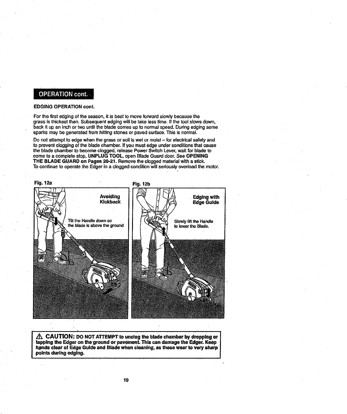
3. TOavoid I_ickbackof Edger. tiltthe Handle down so the blade is abovethe ground (Fig. 12a).
4. Turn Edger On and allow blade to spin without moving tool.
5. Slowly lift the Handle to lower the Blade, finding the edge of the paved sur(ace (Fig, 12b).
Use the Cut Line Indicator to help position the Edger. Start edging, moving the too! forward
slowlyalong edge of paved surface, keeping the Edge Guide pressed lightly against the
pavement edge.
: NOTE: ALWAYS stand to the left of the Handle. Any'debris thrown by the Ed'ger "
f . j
would be coming from the Blade Guard area on the right of the Edger
18
Page 19
EDGING OPERATION cont.
For the first edging of the season, itis best to move forward slowlybecause the
grass is thickest then. Subsequent edging wi!l be take less time. If the tool slews down,
back it up an inch or two until the blade comes up tQ normal speed. During edging some
sparks may be generated from hitting stones or paved surface. This is normal.
Do not attempt te edge when the grass or sell is wet er moist- for electrical safety and
tOprevent clogging of the blade chamber. If you mustedge under conditions that cause
the blade chamber to become clogged, release Power Switch Lever, wait for blade to
come to a complete stoP,UNPLUG TOOL, open Blade Gua_ door. See OPENING
THE BLADE GUARD on Pages 20-21. Remove the cloggedmaterial with a stick.
To continueto operate the Edgerin a clogged conditionwillseriouslyovertoadthe mQtor.
Fig. 12a Fig. 12b
/
/t_ CAUTION: DO NOT ATTEMPT to unclog the blade chamber by dmppi!_! er i
tapping the Edger on theground er paveme.L This can damage the F._r. Keep I
h_nds clear of Edge Guide and Blade when cleaning, as these wear to very sharp I
points during edging. , l
19
Page 20

TRENCHINGANDLANDSCAPINGOPERATION
TheEdgercanalsobeused'forTrenching.Thebladewillleaveasmalltrenchfor placing
wiringunderground.
Because of the directionof the Bladerotation the Edger can+kickbacktowardsthe operatot
if it hitsan obstructionsuchas thick_matted grass. Keep a firm grasp onthe Handle,
especiallywhen trenchingin thick,matted m,_terlaL
The Edger can be used in Landscapingapplicatio'ns, includingcuttingalor_gthe edges
of flower and shrubberybeds,aroundtrees, and cuttingin preparation for sod removal.
While trenchingand landscaping,the EdgeGuidecan interferewith movingthe Edger
throughhard soilor sod. For thisreason trenching and landscapingare donewith the
Blade onlyand withoutuse of the Edge Guide. Locate the Edge GuideAdjustmentLaver
andput Edge Guide inthe up position. Refer toillustrationsOn Lever.
Beforetrenching,inspect and ensure there are no exposed or busedcables, pipes
or other objectsthat may create a hazard or interfere with operatingtheEdger.
Set depthto only that required for the job.
NOTE: ALWAYS stand to the left of the Handle. Any debris thrown by the Edger
would be coming from the Blade Guard area on.the right of the Edge_'.
Do not overload.If tootslowsdown, pull back slightlyand wait untilblade comes uptO
normal speed,
: /_ WARNING: DO NOT use Edger with any type of accessory or attachmenL
Such usage might be hazardous.
OPENING THE BLADE GUARD
The Blade Guard swings open for cleanihg inside the btade chambei" or for changing blades.
To open the Blade Guard:
t. Unplug t0ol.
2. Wait.for blade to come to a COMPLETE STOP.
Z_ WARNING: To avoid injury, ALWAYS turn off and discor_nect the Edger
from the power outlet BEFORE installing parts or cleaning the Edger or making
any adjustments. " .
- ,J 1,_,,- ,., , _ .... _r_ , i_J
CAUTION: BLADE ROTATES momentarily after power Switch iS released'o I
Wait for blade to Come to a complete stop. " •
3. To open Blade Guard, loosenthe Screw under the Blade Guard Release Lever counter-
clockwise(as you face Blade Guard side of tool),see Fig. 13a. Pullout on the Guard
Release Lever and openBlade Guard (Fig, 13b).
4. To closeBlade Guard, push in unti! you hear Guard Release Lever clickinto place.
Tightenthe Screw under the Blade Guard Release Lever.Make sure BladeGuard is
securely in place.
2O
Page 21

OPENING THE BLADE GUARD conL
Fig. 13a
Loosen Screw
WARNING: BE SURE GUARD IS PROPERLY CLOSED AND SC EwED
SHUT BEFORE OPERATING EDGER.
REMOVING AND ATTACHING THE BLADE
The blade, two spacers and hex headnut with conicalwasher shouldbe attached to your
Edger in the order shown (Fig. 14). Check that the blade has been properlymounted before
usingyour Edger.
The Edger Bladehas twowear indicatorsthatshowwhen the odgina!bladeneedsto be
replaced. When the blade wears to the small holes, it should be replaced.
I NOTE: To increase blade life, keep Initial cuffing depl_ at minimum and
increase depth setting as blade wears.
21
Page 22

REMOVINGTHE BLADE FOR REPLACEMENT
/k CAUTtON:B_DE ROTATESmome.tatlly after powerswitch is released.Wait
for blade to come to a complete stop. Blade is sharp, wear work gloves when replacing.
t. Loosen Screw underBlade Guard Release Lever, pull Blade Guard Release Lever
and open Blade Guard Door.See OPENING THEBLADE GUARD on Pages 20-21,
2. Use a t" crescentwrenchto holdthe outerspacerin place,which will keep the blade
from turning,Witha 9/16" crescentwrench,toosen the hex head nut,withconical
washer (Fig. t5a).
3. Remove hex head nut with cohicalwasher, spacer and blade.
Hex Head Nut
with_ontca!washer
ATTACHING THE NEW BLADE
I
I NOTE: Clean off debris from blade and all mounting hardware.
1. Be sure {nnerspacer s on shaft - =flats" in spacer hole mustengage with;'liars"
on shaft(Rg 15b).
2. Place the bladeonthe shaftover the innerspacer.
=3. Hod the bade againstthe inner spacerand installthe outer spacer.
=againaligningtheflats in the spacer with the fiats on the shall
4. Installthe hex headnut with conicalwasher. Use a 1"crescentwrench tb holdthe
outer spacer in place, which wil!keep the blade from turning.With a 9116"Crescent
wrench,firmly tightenthe hex head nutwith conicalwasher (Fig 15a).
t OTE: Replace the hex head nut with conical washer ONLY with idenUcal
replacement part; see Parts List.
5. Close Blade Guard door.Blade Guai'd Release Lever mustsnap into locked position.
Tightenscrew under Blade Guard Release Lever.
22
Page 23
GENERAL MAINTENANCE
Keep your Edger clean and in good repairfor maximumlong-lastingpe_orrnance.
Before each use, inspectthe switchand cordfor damage. Check for damaged, missing,
or worn parts.Check for loose screws,misalignment, moving partsthat are jammed,
or any other conditionsthat may affectthe operation. Ifabnormal v_brationor noise occurs,
turn off the tool immediatelyand have the problemcorrectedbeforefurther use.
• DO NOT use the Edger if it has any broken parts.Have damaged, missing, worn or broken
parts replaced befOreusing Edger.
When servicing a tool, use only identicalreplacementpads. Use of unauthorized pads
or failure to follow maintenanceinstructions may create a risk of electricshockor injury.
BLADE CARE
The cuttingblades are made from high quality, hardened steel and wifh normaluse,
they will•not require resharpaning.However,if youaccidentally hit a wire fence, stones,
glass or other hard objects,you may put a nick in the blade. There is no need to*rem0ve
this pick as longas it does not interferewith the movementof the blade. If it does interfere,
,unplug the Edger, see OPENING THE BLADE GUARD on Pages 2g-21, and use a
fine-toothedfile or sharpeningstone to remove the nick.
= • ,
I Z_ WARNING: To avoid Injury, ALWAYS mr" effanddlsconn_t =e Edg.er !
I from theePOWer=outletBEFORE installing parts or-cleaning the Edger or making I
!, any adjuszments, , , . . !
|f Y0U.droptile .Edger,carefully inspectit for damage. If the bladeis bent, hauslngGrecked,
or handles brOken,or if yousee any other condition that may affect the Edger's Operation,
•have Edger repaired by a Sears or other qualified service dealer before putting it baGkinto
use.
CLEANING
Fertilizersand othergardenchemicals containagents that greatlyac_lemte the corrosion
of metals, tf you use the Edger inareas where ferttliz_'s or chemi_.,_lshave beenused, it
-should be cleaned immediatelyafterwards.DoNot store the toolon er sdja_ent k) fed.itizers
or chemicals.
When cleaning, DO NOT immersetool in wateror squid witha hose_.
Never let any liquidget insidethe tool.
Wipe all exposed parts with a damp cloth. You may lubricateonlymetalpads witha light
_etmleum based oil.
=
/k WARNING: Te avoid injury, ALWAYS turf=eft and dis¢onneGt the _ Jl
from the power cutlet BEFORE Installing parts or cleaning theEdger or nicking !
aP,y adjustments.
• Z_ CAUTION= BLADE ROTATES momenbdly after Pewer 'sw_l_ is re!ea=ed. ]
Wait for blade to come to a complete step.
,
...............................
_
.........
23
Page 24

STORAGE -
Store the Edger indoors when not in use. It shoutd be stored in a dryplace, high up or
locked in a place that is out of the reach of children.
Edger may be Stored by hanging by handle. DO NOT hang Edger with the Power Switch
Lever depressed! Be sure Power Switch Lever is free ot contact when hanging.
Z_ WARNING: Be sure the Edger is unplugged before storing_
DO NOT hang Edger by Power Switch Lever.
Remove and clean off any debris from the outsideof the Edger and inside of Biade Guard
before storage. To clean inside of Blade Guard see OPENING THE BLADE GUARD
on Pages 21_21,
! ,_ WARN|N --_ _The use of att_ohme_t_ or ;acc_so_|es tha_a_ not J
recommended for this tool might be dangerous and could result in serious injury.
.,_.
REPLACEMENT. BLADES
Replacement blades are available at Sears stores or Sears.com.
The replacement blade fop your Edger is Seat's item number #11000.
Visit your local Sears store or Other Craftsman outlets or shop sears.comlcraftsman.
Page 25

12 Amp
Electric
Lawn Edger
Mod4iNa t72,_t83
Page 26

12 Amp
Electric Lawn Edger
Model.No. 17"2.7g'183
The.modelnumberwiltt}efoundon thenameplateofthe:Edger.
Always mentionthe modelnumberwhenreque_ng parts andservce for yourtool.
_tem No, Parts NO. Part Descriptioll Oty,
I Self Tapptnq Screw 4
2 GLE150U-2 SwitchCover Right 1
3 GLE150U-3 Torsional Spr ng 1
4 ..............GLE1.50U-4 Two Pronq Power P[uq _ =' " 1
5 . .GLEO 50U:5 , _Powe,r,Swffc,h Lever 1
6 GLE150U_6 Rubber Tube For Handle I
7 GLEt 50U-7 Switch I
8 . GLE150U-8 Hand!,e 1
9 GLEt 50U-9 Tube Plu_l l
.. 101 . GLE$5OLI-101 ..............Switch
10 GLE150U-10, Self Tapp n,q Screw ...... 1' 45
GLEtSOU'l_
11 •
I GLE150U'12
__ 13
..... 20.
• 27 GLE150U-27.
• GLE150U-13
' GLE150U't4
15
GLE150U'15
GLE150U-16
16
.....GLE150U_17
17
GLEISOU-1B
.18
19
GLE150U*19
GLE150U-20
,, GLE,150U-21 ,_
, 22
....2,3,
.... 31 ..... GEEi_LI-31
GLE 150U-22
GLE150U:83,
24
• GLE150U-24
25.
• GLE150U-25
26'
28 GLEtSOU-2B
29 : GLEISOU-29
30 GLE1501_30,,
10 GLE150U-i0
32 GLE150U-32
33 . IGLE150U_33
34 GLE150U-34
C0V_r
Switch ,Leve_ 1
............Switch Cover Left ................. 1 .
Comp,_eseion Sprino _1
Power Safety Loek-O_,,,,Switch 1
......Insulation Sheath ..... t
.Upoer Tube . 1
Cord Retainer With Hook ' 1
.....Curved Head Botts ............. 2
Inner Line
B|aek Pla_tioTube C,oatin.q
,,,Lower Tube
Washer
Nut
Lockin_q Kno_ .......
Bolt
Hex, Nut wLCqnicaf. Washer
Spacer
'Blade
.,,Screw Washer Assembly
Edae Guide
Self Talopin_ SoreW F-.I
Guard Retease Lever,
Blade Guard,Cove.r
Torsenia[ Spr n_q
! It
L,I"
1"
1
2,
3,
2
1'
I.
I
!,
2.
1
1
6'
1/
Item No.
......42
_ ,44
" 52
" Parts NO, ] part Description
35,
GLEt50U-35 Cy!indriCa_lPin
GLE!50U-36
GLEi50U-37
37
38
GLE150U-38 ] Revolve P.!n
59
GLE150U-39 i Li[nit PJate
4O
GLE150U-40 . . Cord Clamp
41
GLE150U-41 Setf Tapping Screw
'"GLE150U-42 ,Rear Ro]l_r S_ft
43
GLE150U'43
GLEtSOU-44.
GLE150U-45
46.
GLIE1 _0Ur46 ........
47
GLE150U-47
48
G LEt 50U-48 .........
4g.
GLE150U-49o
GLE150U-50
50
51
GLEt 50U:-51,,,,, , Sprin_l: Pin
"53' '
..... 54 _ I""'"GLE15,0U-54
55 GLE15QU_55,
.56 ..........GLE150U_56
57 GLE_ 50U-57'
.....58 GLE150U-58
59 GLE150U-59
104 GLE150U-t04
60 GL,EI,I,5OU-6p '
61 .........GLE,150U:61
. 62 , GLE150U_B2
63 GLEl'50U-63
64 . GLEtSOU-64 _ E;a_Bear!ng
•65 GLE150U-65 Wash_'r
66: GLEt_50U_66 SDrinQ Washer .
67 .... GLEl50U-67 ' Screw ,.
.......BB .....GLE_,_OU.6B"', .....................
.... 69,,, GLE150.U-,69:,
Retatabl,e B!ock
......
Compm@_ion Spring ..... 1 ,,,i......
FRButt0n '., . ................. 1 .......
Washer 1
Sleeve _ . 2.......
Rear Wheel 2 ,
' Self TaloD_n_ClScrew . 4
Washer
Rf_ar Coye_
Rear Whee! Guard:
Ad_rustment Knob '
,,Strp
Sorew" _ '"
Decorative Cover ............
Setf,Tappinq Screw i ..................
R .qht Blade Guard Housin_
Motor Set
Nut
_ear Bra<;ket '..... ,,,,
Starer
Front Bracket .....
Qty.
2
•i
!: ..........
1
...................... i ........
2
1
2
1
2"
t
1
!
1 ........
.........13.,,
1
1
1
1
1
1
6
6
1
Page 27

12Amp
Electric Lawn Edger
M_de! No. 17279183
Item No.
Themodelnumberwillbefound,onthenameplateoftheEdger.
Alwaysmentionthemodelnumberwhenrequesting,partsandserviceforyourtoo,
1'
1
1
76
4
3
1
1
Page 28

.For repair - in your home- Ofall major brand appliances,
lawnand garden equipment, or heating and coolingsystems,
no matter who made it, no matter who sold itl
For the replacement parts,accessoriesand
owner's manualsthatyou needto.do-it-yourself."
For Sears professionalinstallationof home appliances
and itemslikegarage door openerSand water heaters.
1-800-4-MY-HOME® Ca,anytime,dayor,ight
(1-800-469-4663) (U.S,A. and Canada)
www,sears,com www.sears.ca
Our Home . .
For repairof carry-in items like vacuums,lawnequipment; .
and electronics,callanytime for the locationof.the nearest .
Sears Parts & Repair Service Center
1-800..488-1222 (U.S.A.) 1-;800-469_663 (Canada)
www.sears.com www.sears.ca
To purchasea protectionagreementon a product serviced bySears:
1-800_827-6655 (u.s.A.)
!',800-361-6665 (Canada)
Parapedirserviciode reparaci6n
a domicllio,y paraordenarpiezas:
1-888-SU-HOGAR®
(1-888-764_427)
www.seats.com
® Registered Trademark t _t Trademark of KCD IP, LLC in the United States, or Seats Brands, LLC in other Countries
® Ma, r_a Registzada / Matca de F_btica de KCD |P, LLC en Es_ados Unides, o Seam Brands, LLC fn otres paises
ac Marque de commerce / _ Marque d_pos_e de Sea{s Brands, LLC =,
IM
Au Canadapourserviceen fran_ais:.
1-800_LE-FOYER_
www.sears.ca
 Loading...