

Page 1
Operator’s Manual
®
P R O F E S S I O N A L
7 Amp
31/4-in. Planer
Model No.
172.26729
3/64
0
CAUTION: Read, understand and follow
all Safety Rules and Operating Instructions
in this manual before using this product.
Sears, Roebuck and Co., Hoffman Estates, IL 60179 U.S.A.
Visit our Craftsman® website: www.sears.com/craftsman
1/32
1/64
Double Insulated
• WARRANTY
• SAFETY
• UNPACKING
• DESCRIPTION
• OPERATION
• MAINTENANCE
Page 2
TABLE OF CONTENTS
SAFETY SYMBOLS
Warranty……………………………...................................……………...Page 2
Safety Symbols……………………………...................................……... Page 3
Safety Instructions…………………………...................................……..Pages 4-9
Unpacking ………………………………..................................……........Page 9
Description............................................................................................Pages 10-11
Operation..............................................................................................Pages 12-17
Maintenance.........................................................................................Pages 18 -19
Accessories...........................................................................................Page 19
Parts List...............................................................................................Pages 20 -21
Sears Repair Parts Phone Numbers.....................................................Back Cover
ONE YEAR FULL WARRANTY ON CRAFTSMAN PROFESSIONAL TOOL
If this Craftsman Professional Tool fails due to a defect in material or workmanship
within one year from the date of purchase, RETURN IT TO ANY SEARS STORE OR
PARTS AND REPAIR CENTER OR OTHER CRAFTSMAN OUTLET IN THE UNITED
STATES FOR FREE REPAIR (OR REPLACEMENT IF REPAIR PROVES
IMPOSSIBLE).
This warranty does not include expendable parts such as lamps, batteries, bits or
blades.
This warranty gives you specific legal rights, and you may have other rights, which
vary from state to state.
Sears, Roebuck and Co., Hoffman Estates, IL 60179
SAVE THESE INSTRUCTIONS!
READ ALL INSTRUCTIONS!
The purpose of safety symbols is to attract your attention to possible dangers.
The safety symbols, and the explanations with them, deserve your careful
attention and understanding. The symbol warnings DO NOT by themselves
eliminate any danger. The instructions and warnings they give are no substitutes
for proper accident prevention measures.
!
WARNING:
this manual, including all safety alert symbols such as “DANGER”, “WARNING”
and “CAUTION”, BEFORE using this planer. Failure to follow all instructions
listed below may result in electric shock, fire and/or serious personal injury.
SYMBOL MEANING
CAUTION. May be used in conjunction with other symbols or pictographs.
DANGER
WARNING
CAUTION
DAMAGE PREVENTION AND INFORMATION MESSAGES
These inform user of important information and/or instructions that could lead to
equipment or other property damage if not followed. Each message is preceded
by the word “NOTE:” as in the example below:
SAFETY ALERT SYMBOL: Indicates DANGER, WARNING, OR
!
!
!
!
BE SURE to read and understand all safety instructions in
Failure to obey this safety warning WILL result in death or
serious injury to yourself or to others. Always follow the
safety precautions to reduce the risk of fire, electric shock
and personal injury.
Failure to obey this safety warning CAN result in death or
serious injury to yourself or to others. Always follow the
safety precautions to reduce the risk of fire, electric shock
and personal injury.
Failure to obey this safety warning MAY result in personal
injury to yourself or others or property damage. Always
follow the safety precautions to reduce the risk of fire,
electric shock and personal injury.
!
WARNING:
known to the State of California to cause cancer and birth defects or other
reproductive harm.
Some dust created by using power tools contains chemicals
2
NOTE: Equipment and/or property damage may result if these instructions are
not followed.
!
WARNING:
The operation of any tool with a cutting
blade can result in foreign objects being thrown into your
eyes, which can result in severe eye damage. Before
beginning power tool operation, ALWAYS wear safety
goggles or safety glasses with side shield and a full-face
shield when needed. We recommend a Wide Vision Safety
Mask for use over eyeglasses or standard safety glasses
with side shield, available at Sears Stores or other
Craftsman Outlets.
3
Page 3
SAFETY INSTRUCTIONS
SAFETY INSTRUCTIONS cont.
!
WARNING:
before using this planer. Failure to follow all instructions may result in electric shock,
fire and / or serious personal injury.
BE SURE to read and understand all instructions in this manual
WORK AREA SAFETY
1. Keep your work area clean and well lit. Cluttered workbenches and dark areas
invite accidents.
2. DO NOT operate power tools in explosive atmospheres, such as in the presence
of flammable liquids, gases, or dust. Power tools create sparks which may ignite the
dust or fumes.
3. Keep bystanders, children and visitors away while operating a power tool.
Distractions can cause you to lose control.
4. Make your workshop childproof with padlocks and master switches. Lock
tools away when not in use.
5. MAKE SURE the work area has ample lighting so you can see the work and that
there are no obstructions that will interfere with safe operation BEFORE using
your planer.
PERSONAL SAFETY
1. KNOW your power tool. Read the operator’s manual carefully. Learn the planer’s
applications and limitations, as well as the specific potential hazards related to this tool.
2. STAY ALERT, watch what you are doing and use common sense when operating a
power tool.
3. DO NOT use tool while tired or under the influence of drugs, alcohol or medication.
A moment of inattention while operating power tools may result in serious personal
injury.
4. DRESS properly. DO NOT wear loose clothing or jewelry. Pull back long hair. Keep your
hair, clothing, and gloves away from moving parts. Loose clothing, or long hair can be
caught in moving parts. Air vents often cover moving parts and should also be avoided.
5. AVOID accidental starting. Be sure switch is in “OFF” position before plugging in.
DO NOT carry tools with your finger on the switch. Carrying tools with your finger on the
switch or plugging in tools that have the switch in the “ON” position invites accidents.
6. REMOVE adjusting keys or blade wrenches before turning the tool “ON”. A wrench that
is left attached to a rotating part of the tool may result in personal injury.
7. Do not overreach. Keep proper footing and balance at all times. Proper footing and
balance enables better control of the tool in unexpected situations.
8. ALWAYS SECURE YOUR WORK. Use clamps or a vise to hold work when practical.
It is safer than using your hand and frees both hands to operate tool.
9. USE SAFETY EQUIPMENT. Always wear eye protection. Dust mask, non-skid safety
shoes, hard hat, or hearing protection must be used for appropriate conditions.
TOOL USE AND CARE SAFETY
!
WARNING:
operating this planer. Failure to follow all instructions listed below may result in
electric shock, fire and/or serious personal injury.
1. ALWAYS use clamps or other practical ways to secure and support the
workpiece to a stable platform. Holding the work by hand or against your body
is unstable and may lead to loss of control.
2. DO NOT force the tool. Use the correct tool and blade for your application. The
correct tool and blade will do the job better and safer at the rate for which it is designed.
3. DO NOT use the tool if switch does not turn it “On” or “Off”. Any tool that
cannot be controlled with the switch is dangerous and must be repaired.
4. DISCONNECT the plug from the power source before making any
adjustments, changing accessories or storing the tool. Such preventive
safety measures reduce the risk of starting the tool accidentally.
5. STORE idle tools out of the reach of children and other untrained persons.
Tools are dangerous in the hands of untrained users.
6. MAINTAIN tools with care. Keep cutting tools sharp and clean. Properly maintained
tools with sharp cutting edges are less likely to bind and are easier to control.
7. CHECK for misalignment or binding of moving parts, breakage of parts, and
any other condition that may affect the tool’s operation. If damaged, have the
tool serviced before using. Many accidents are caused by poorly maintained tools.
8. USE ONLY accessories that are recommended for this tool. Accessories that
may be suitable for one tool may become hazardous when used on another tool.
BE SURE to read and understand all instructions before
ELECTRICAL SAFETY
!
WARNING:
installing or removing the plug from the outlet.
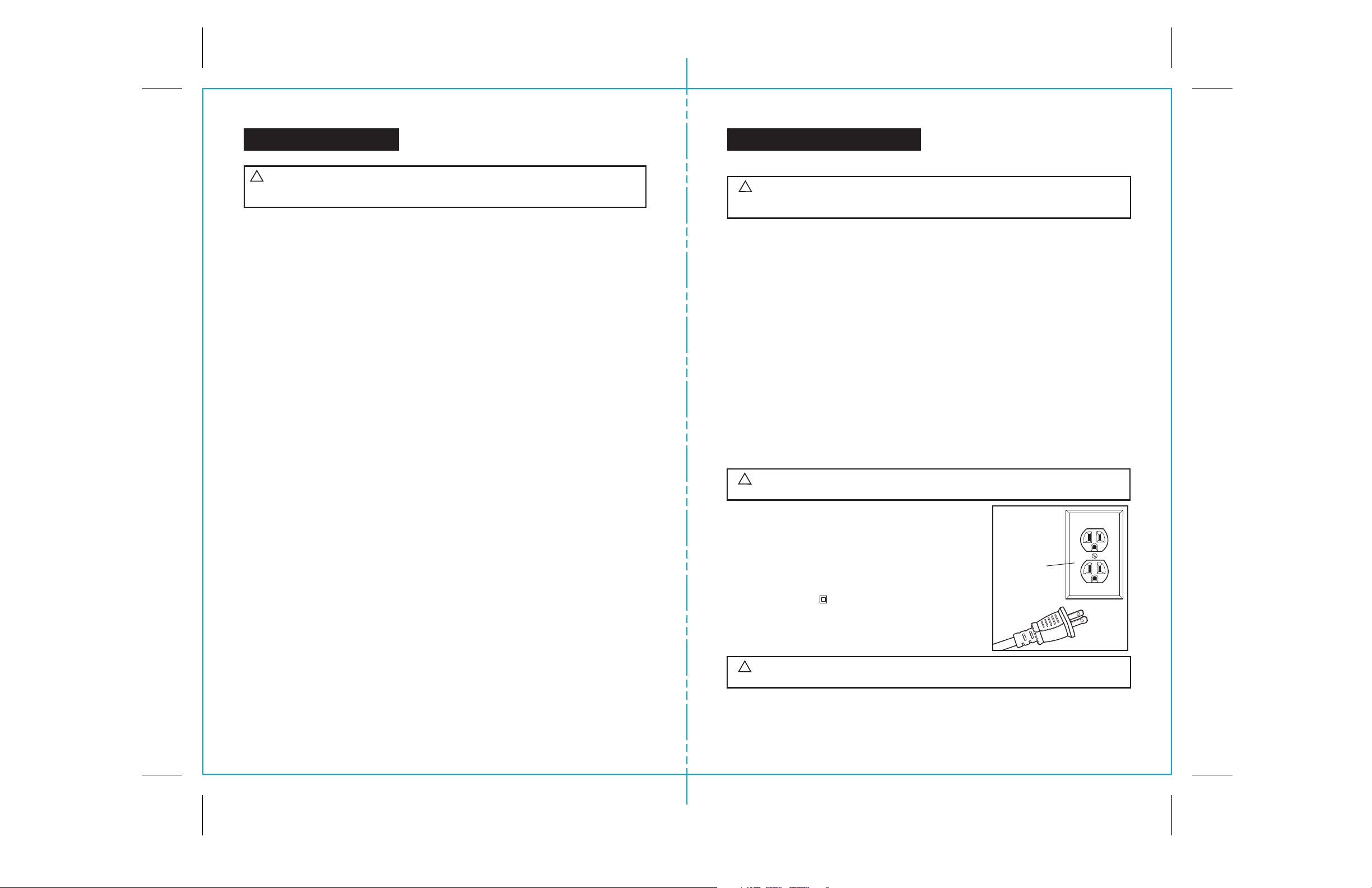
1. Double insulated tools are equipped
with a polarized plug (one blade is wider
than the other). This plug will fit in a
polarized outlet only one way. If the plug
does not fit fully in the outlet, reverse the plug.
If it still does not fit, contact a qualified
electrician to install a polarized outlet. Do
not change the plug in any way.
2. Double insulation eliminates the need
for the three-wire grounded power cord and
grounded power supply system. Applicable
only to Class II (double-insulated) tools.
This planer is a double insulated tool.
!
WARNING:
precautions when operating this tool.
Do not permit fingers to touch the terminals of plug when
Cover of
Grounded
Outlet Box
Double insulation DOES NOT take the place of normal safety
3. BEFORE plugging in the tool, BE SURE that the outlet voltage supplied is within the
voltage marked on the tool’s data plate. DO NOT use “AC only” rated tools with
a DC power supply.
4
5
Page 4
SAFETY INSTRUCTIONS cont.
SAFETY INSTRUCTIONS cont.
ELECTRICAL SAFETY cont.
4. AVOID body contact with grounded surfaces, such as pipes, radiators, ranges and
refrigerators. There is an increased risk of electric shock if your body is grounded.
5. DO NOT expose power tools to rain or wet conditions or use power tools in wet
or damp locations. Water entering a power tool will increase the risk of electric shock.
6. INSPECT tool cords for damage. Have damaged tool cords repaired at a Sears
Service Center. BE SURE to stay constantly aware of the cord location and keep it well
away from the moving blade.
7. DO NOT abuse the cord. NEVER use the cord to carry the tool by or to pull the
plug from the outlet. Keep cord away from heat, oil, sharp edges or moving parts.
Replace damaged cords immediately. Damaged cords increase the risk of electric shock.
EXTENSION CORDS
Use a proper extension cord. ONLY use cords listed by Underwriters Laboratories (UL).
Other extension cords can cause a drop in line voltage, resulting in a loss of power and
overheating of tool. For this tool an AWG (American Wire Gauge) size of a least 14-gauge
is recommended for an extension cord of 25- ft. or less in length. Use 12- gauge for an
extension cord of 50-ft. Extension cords 100-ft. or longer are not recommended.
Remember, a smaller wire gauge size has greater capacity than a larger number
(14-gauge wire has more capacity than 16-gauge wire; 12-gauge wire has more capacity
than 14-gauge). When in doubt use the smaller number. When operating a power tool
outdoors, use an outdoor extension cord marked “W-A” or “W”. These cords are rated for
outdoor use and reduce the risk of electric shock.
SAFETY SYMBOLS FOR YOUR TOOL
The label on your tool may include the following symbols.
V.......................................................................Volts
A......................................................................Amps
Hz....................................................................Hertz
W.....................................................................Watts
min..................................................................Minutes
....................................................................Alternating current
.................................................................Direct current
no ....................................................................No-load speed
....................................................................Class II construction, Double Insulated
.../min..............................................................Revolutions or Strokes per minute
.....................................................................Indicates danger, warning or caution.
!
It means attention! Your safety is involved.
SERVICE SAFETY
1. If any part of this planer is missing or should break, bend, or fail in any way;
or should any electrical component fail to perform properly: SHUT OFF the
power switch and remove the planer’s plug from the power source and have the
missing, damaged or failed parts replaced BEFORE resuming operation.
2. Tool service must be performed only at a Sears Service Center. Service or
maintenance performed by unqualified personnel could result in a risk of injury.
3. When servicing a tool, use only identical replacement parts. Follow
instructions in the maintenance section of this manual. Use of unauthorized
parts or failure to follow maintenance instructions may create a risk of
electric shock or injury.
SAFETY RULES FOR PLANERS
!
CAUTION:
cord so that it will not get caught on lumber, tools or other obstructions while
you are working with a power tool.
!
WARNING:
immediately. Never use tool with a damaged cord since touching the damaged
area could cause electrical shock, resulting in serious injury.
Keep the extension cord clear of the working area. Position the
Check extension cords before each use. If damaged replace
6
!
DANGER
Keep hands away from cutting area and blade. Keep both
hands on the planer (rear handle and front handle). If both hands are holding
the planer, the blade cannot cut them.
1. ALWAYS use both hands when using the planer. Hold the front handle with your
left hand and the rear handle with your right hand.
2. Operate the planer with the chip chute exhaust turned so it points away from your
face and eyes.
3. To insure control, ALWAYS support your workpiece so the cut will be on your
right.
4. ALWAYS clamp the workpiece securely so it will not move when making the cut.
5. DO NOT use dull or damaged blades. Bent blades can break easily, or cause
kickback resulting in loss of control and serious injury.
6. ALWAYS hold the planer so the blades DO NOT come in contact with the
workpiece until you have squeezed the trigger switch and the planer has started.
7
Page 5

SAFETY INSTRUCTIONS cont.
SAFETY INSTRUCTIONS cont.
!
WARNING:
Some dust created by using power tools contains chemicals
known to the State of California to cause cancer and birth defects or other
reproductive harm. Some examples of these chemicals are:
• Lead from lead-based paints.
• Crystalline silica from bricks and cement and other masonry products.
• Arsenic and chromium, from chemically treated lumber.
Your risk from these exposures varies, depending upon how often you do
this type of work. To reduce your exposure to these chemicals:
• Work in a well-ventilated area.
• Work with approved safety equipment, such as those dust masks that
are specially designed to filter out microscopic particles.
Avoid prolonged contact with dust from power sanding, sawing, grinding,
drilling and other construction activities. Wear protective clothing and wash
exposed areas with soap and water. Allowing dust to get into your mouth,
eyes, or lay on the skin may promote absorption of harmful chemicals.
!
WARNING:
Use of this tool can generate and/or disburse dust, which may
cause serious and permanent respiratory or other injury. Always use
NIOSH/OSHA approved respiratory protection appropriate for the dust exposure.
Direct particles away from face and body.
ADDITIONAL RULES FOR SAFE OPERATION
!
WARNING:
Failure to follow all instructions listed below may result in electric shock, fire
and/or serious personal injury.
BE SURE to read and understand all instructions.
ADDITIONAL RULES FOR SAFE OPERATION cont.
8. SAVE THESE INSTRUCTIONS. Refer to them frequently and use them to
instruct others who may use this tool. If someone borrows this tool, make
sure they have these instructions also.
UNPACKING
1. Remove the Planer from the Storage / Carrying Case and inspect it carefully to make
sure that no breakage or damage has occurred during shipping.
2. Do not discard any of the packing materials until all parts are accounted for.
3. The planer has a Crescent Wrench force-fitted into the Storage / Carrying Case.
4. The Edge Guide is force-fitted into the top of the lid of the Storage / Carrying Case.
5. Also included with your planer and force fitted into the Storage / Carrying Case is a
Rabbet Guide.
6. Two blades are included with your planer.
7. If any of the parts are damaged or missing (refer to PARTS LIST below), return the
planer to your nearest Sears store or Craftsman outlet to have the planer replaced.
!
WARNING:
missing parts are replaced. Failure to do so could result in possible serious
personal injury.
PARTS LIST
If any parts are missing, DO NOT operate this planer until the
1. Planer
1. Know your power tool. Read operator’s manual carefully. Learn the applications and
limitations, as well as the specific potential hazards related to this tool. Following this rule
will reduce the risk of electric shock, fire or serious injury.
2. ALWAYS wear safety glasses or eye shields when using this planer. Everyday
eyeglasses have only impact-resistant lenses; they are NOT safety glasses.
3. PROTECT your lungs. Wear a face mask or dust mask if the operation is dusty.
4. PROTECT your hearing. Wear appropriate personal hearing protection during use.
Under some conditions noise from this product may contribute to hearing loss
5. ALL VISTORS AND BYSTANDERS MUST wear the same safety equipment that the
operator of the planer wears.
6. INSPECT the tool cords periodically and if damaged have them repaired
at your nearest Sears Service Center. ALWAYS BE AWARE of the cord location
when operating your planer.
7. ALWAYS check the tool for damaged parts. Before further use of the tool,
a guard or other part that is damaged should be carefully checked to
determine if it will operate properly and perform its intended function. Check
for misalignment or binding of moving parts, breakage of parts, and any other
condition that may affect the tool’s operation. A guard or other part that is
damaged should be properly repaired or replaced at a Sears Service center.
8
mm
0
Inches
0
10
20
112
1
3. Rabbet Guide
8. Operator’s Manual
2. Edge Guide
5. Two Blades
4. Wrench
0
1/64
6. Two Screws
9
3/64
1/32
7. Storage / Carrying Case
Page 6

DESCRIPTION
DESCRIPTION cont.
KNOW YOUR PLANER
NOTE: Before attempting to use your planer, familiarize yourself with all of the
operating features and safety requirements.
Your planer has a precision-built electric motor and it should be connected to a 120-volt,
60-Hz AC ONLY power supply (normal household current). DO NOT operate on direct
current (DC). The large voltage drop will cause a loss of power and the motor will overheat.
If the planer does not operate when plugged into correct 120-volt, 60-Hz AC ONLY outlet,
check the power supply. This planer has a 10-ft., 2-wire power cord (no adapter needed).
This Professional Planer has the following features:
1. Powerful, heavy-duty 7-Amp motor provides high speed needed for fast, clean cuts
in most any type of wood. Precision balanced for smooth, quiet operation.
2. Low profile depth-of-cut control knob allows easy depth-of-cut adjustments from
0 to 1/8-in.
3. Grooved front shoe design for 45° bevel or chamfer cuts.
4. Ergonomically designed contoured top-mount handle and front assist handle
with soft grips for positive gripping, balance, control and comfort.
5. Heavy-duty extended length trigger switch conveniently located for comfort and
control. Lock-off button helps prevent accidental starts.
6. 31/4-inch cutting width for fast planing. Planes wide side of 2 X 4 board in one pass.
7. Uses reversible, double-edged hardened steel carbide-tipped blades that can be
used on both sides for longer blade life.
8. Includes edge guide for accurate, precise cuts on long or uneven workpieces.
9. Includes rabbet guide for making 15/16-in. deep rabbet cuts.
10. Chip chute keeps work surface clean and directs wood chips away from operator.
11. Permanently lubricated bearings for smooth, efficient operation and long life.
12. Cogged timing belt drive provides positive, precise power transmission.
13. High-impact plastic motor housing and handles help protect tool from damage and
reduce weight.
14. Includes high-impact resistant storage / carrying case.
This Professional Planer has the following features:
Fig. 1
Front
Handle
Left or Right
Dust/ Chip
Extraction
0
1/64
Depth Adjustment
Trigger Switch
3/64
1/32
Base plate stand
Knob
PRODUCT SPECIFICATIONS
Input
Cutting Width
Cutting Depth
Max. Rabbet Cut
Rating
No-Load Speed
7 Amps
3 1/4 in.
0 to 1/8-in.
15/16-in.
120 volts, 60 Hz AC
12,000 RPM
Rear Handle
On/Off
Button
10
11
Page 7

OPERATION
OPERATION cont.
!
WARNING: Your planer should NEVER be connected to power supply when you
are assembling parts, making adjustments, changing belts or blades, cleaning planer,
or when not in use. Disconnecting planer will prevent accidental starting that could cause
serious injury.
PREPARING FOR OPERATION
Your planer has a rear handle and front assist handle for ease of operation. They provide
the two-hand operation which is necessary to maintain proper control of the planer.
ALWAYS keep both hands clear of the blades and the cutting area.
ALWAYS use both hands when using the planer. Hold the front handle with your left hand
and the rear handle with your right hand (as shown in Fig, 2). This position makes your
planer easier to handle and keeps you clear of the chip exhaust.
!
CAUTION:
exhaust. Chip build-up restricts air flow and can cause the motor to over heat.
DO NOT plane too fast because this causes build up in the chip
Keep the cord away from the cutting area. ALWAYS place the cord so it does not hang up
on the work when you are making a cut.
!
DANGER: If the cord hangs up on the work during the cut, release the trigger
switch immediately. Unplug the planer and check the cord for damage. If there is no
damage, reposition the cord to prevent it from hanging up again. If the cord has been
damaged, have it replaced before using your planer.
!
WARNING: Using your planer with a damaged cord could cause electrical
shock resulting in serious injury.
THE CORRECT WAY TO USE YOUR PLANER (See Fig. 2)
ALWAYS hold your planer as shown in Figure 2.
1. ALWAYS keep control of your planer. It makes cutting easier and safer, as shown in
Figure 2.
2. To help keep control, ALWAYS support your work so the cut will be on your right.
3. ALWAYS clamp your work so it does not move during the cut (see Figure 2).
The workpiece moving during a cut could result in the loss of control of the planer,
possibly causing serious injury.
The work moving during a cut could result in the loss of control of the planer, possibly
causing serious injury.
THE CORRECT WAY TO USE YOUR PLANER
(See Fig. 2) cont.
Fig. 2
4. ALWAYS operate the planer with the chip chute
exhaust turned so it points away from your face
and eyes.
All visitors should wear safety glasses and be kept
a safe distance from the work area.
5. ALWAYS hold your planer so the blades DO NOT
3/64
1/32
0
1/64
come in contact with the work piece BEFORE
you squeeze the trigger switch and start the
planer.
!
WARNING: Keep a firm grip on the
tool with both hands at all times. Failure to do so
could result in loss of control leading to possible
serious injury.
TO ADJUST PLANING DEPTH (See Fig. 3)
The planing depth on your planer can be adjusted from 0 to 1/8 inch by rotating the depth
adjustment knob located on the front of your planer.
1. Unplug your planer.
!
WARNING: Failure to unplug your planer could result in accidental starting,
causing serious injury.
2. To increase cutting depth, rotate knob in a
clockwise direction.
Fig. 3
3. To decrease cutting depth, rotate knob in a
counterclockwise direction.
4. We recommend that you make test cuts in scrap
wood after each adjustment to make sure the
planer is removing the desired amount of wood.
NOTE: To protect the blades during storage,
transporting and when not in use, ALWAYS set
the blade depth adjustment to 0.
7
/
6
4
i
n
c
h
1/64
0
Depth
Adjustment
Knob
To Increase
Cutting Depth
Turn Clockwise
To Decrease
Cutting Depth Turn
Counterlockwise
12
13
Page 8

OPERATION cont.
OPERATION cont.
GENERAL CUTTING
1. Adjust planer to desired depth.
2. ALWAYS grip the planer with your left-hand holding the front handle and your right
hand holding the rear handle.
3. Place front shoe flat on the work piece. ALWAYS make sure that the blades are not
touching the work piece.
4. Apply pressure to the front handle until the front shoe is flat on the work piece.
5. Push the On/Off button and Squeeze the trigger switch to start the planer and allow the
motor to reach maximum speed.
6. Hold the planer firmly and push it steadily in a forward direction onto the work piece.
NOTE: If you desire a smooth cut, push the planer slowly in a forward direction.
7. As you reach the end of your desired cut, ALWAYS apply downward pressure toward
the rear handle. This will help keep the rear section of the base in contact with the work
piece and help prevent the front of the planer from dipping and gouging your cut.
8. ALWAYS be careful to avoid hitting nails during the planing operation because this
could nick, crack or otherwise damage the blades.
NOTE: The blades in your planer are reversible, so they can be rotated until both
sides are dull.
NOTE: We suggest that you keep an extra set of blades on hand, so you can replace the
blades in your planer when they show signs of becoming dull. Always reverse or replace
blades in pairs.
EDGE PLANING / CHAMFERING (See Figure 4)
Your planer is designed with a groove in the front shoe. This groove is for chamfering the
edges of boards (see Fig. 4).
NOTE: ALWAYS make a practice cut on scrap wood to determine how much wood needs
to be removed from the board BEFORE making your actual cut.
1. Firmly hold the rear handle of the planer with
your right hand and the front handle with your
Fig. 4
left hand.
2. Place the groove of the planer on to the surface
to be cut.
3. Turn on planer and let it reach full speed.
4. Slowly move planer onto work.
0
1/64
1/32
3/64
5. ALWAYS maintain downward pressure on the
planer to keep it flat at the beginning and the
end of the work piece.
NOTE: Making several passes of more shallow
cuts will provide a smoother cut and makes it
easier to control planer.
ACCESSORIES INCLUDED WITH YOUR PLANER
To make your planer even more versatile we have included 2 special accessories.
They are an Edge Guide and a Rabbeting Plate.
ATTACHING THE EDGE GUIDE (See Figure 5)
1. Unplug your planer.
!
WARNING: Failure to unplug your
Fig. 5
planer could result in accidental starting,
causing serious injury.
2. Insert the screw provided through the hole in
7
/
6
4
i
n
c
h
0
1/64
Screw
the edge guide.
3. Tighten screw securely into screw hole on
either side of the main shoe (see Fig. 5).
USING THE EDGE GUIDE
Edge
Guide
The Edge Guide easily attaches to either side of
the planer. It is ideal for planing long and uneven boards.
1. When making cuts with the Edge Guide ALWAYS hold it firmly against the edge of the
board you are planing.
ATTACHING THE RABBET GUIDE (See Fig. 6)
1. Unplug your planer.
!
WARNING: Failure to unplug your planer could result in accidental starting,
causing serious injury.
2. Insert the screw provided through the flat washer, then through the slot in the rabbeting
plate.
3. Insert screw into screw hole on the right side
of the main shoe and tighten securely
Fig. 6
(see Fig. 6).
USING THE RABBET GUIDE
The Rabbet Guide attaches to the right side of
the planer. It is ideal for making rabbeting cuts
up to 15/16 inches thick.
The maximum width of cut is 15/16-inch
per cut.
7
/
6
4
i
n
c
h
1/64
0
1. When making a rabbet cut, ALWAYS place
the notch on the inside of the main shoe firmly
against the side of the board (see Fig. 6).
2. ALWAYS press the Rabbet Guide firmly
against the top surface of the board.
Screw
Rabbet
Guide
Main
Shoe
Notch
14
15
Page 9

OPERATION cont.
OPERATION cont.
TO ADJUST THE DEPTH OF RABBET CUT
1. Unplug your planer.
!
WARNING: Failure to unplug your planer could result in accidental starting,
causing serious injury.
2. Place planer on a flat board or work piece.
3. Loosen the screw and position the bottom surface of the Rabbet Guide above the
board the same distance as the desired depth of cut.
4. Tighten screw securely.
REPLACING THE BLADES (See Figures 7 to 9)
The blades in this planer are reversible, so when the blades become dull, they can be
reversed.
ALWAYS REPLACE OR REVERSE THE BLADES IN PAIRS.
DO NOT ATTEMPT TO SHARPEN THE BLADES.
NEVER OPERATE YOUR PLANER WITH ONLY ONE BLADE INSTALLED.
1. Unplug your planer.
!
WARNING: Failure to unplug your planer could result in accidental starting,
causing serious injury.
2. Place the planer upside down on the work bench. (See Fig. 7).
3. Use the wrench (included) to loosen the 3 bolts that hold the blade to the blade clamp.
To loosen bolts, turn them approximately 1/2 turn in a clockwise direction. (See Fig. 7).
4. Hold the blade clamp in position and use a piece of wood to slide the blade out of blade
clamp. (See Fig. 8).
5. Push down on blade guard when removing the blade from the blade clamp. (See Fig. 8).
Fig. 7
Wrench
Bolts
Planer
Blade
Clamp
Fig. 8
Piece
of
Wood
Blade
Blade
Clamp
REPLACING THE BLADES (See Figures 7 to 9) cont.
!
CAUTION: Blades are very sharp. ALWAYS handle blades very carefully.
Failure to do so could result in possible serious injury.
NOTE: DO NOT remove the blade clamp. This could alter the factory setting for cutting
height and blade height.
NOTE: DO NOT adjust the height adjusting screws.
Fig. 9
Blade
Clamp
6. Place new blade or reverse existing blade into
blade clamp. (See Fig. 9).
7. Check to be sure blade is properly positioned in
blade clamp and the blade edge is level with the
base. (See Fig. 9).
8. Securely re-tighten the 3 bolts.
Wrench
Blade
Bolts
9. Repeat the steps 3 through 8 above to change
or reverse the other blade.
10. Remove piece of wood from planer.
!
Warning: ALWAYS remove the piece of wood before starting your planer.
Failure to do so could result in the piece of wood being thrown from your planer, causing
possible serious injury.
USING THE LEFT OR RIGHT DUST / CHIP
EXTRACTION (See Figure 10)
Fig. 10
The dust / chip chute can be adjusted for left or right
extraction. Turn chute clockwise for extraction on the
left side, or turn it counterclockwise for extraction on
the right side. The arrow on the top of the chute
indicates the direction the chips will be extracted.
bi-directional dust extraction system
Work
Bench
16
Blade Guard
17
Page 10

Page 11

PARTS LIST
PARTS LIST cont.
42221112111111112111111111111211211
L
N
U
L
N
E
C
Q
S
X
P
R
POWER PLANER – MODEL NUMBER 172.26729
Screw
Description QuantityPart No.
SW57.24.0-00
3637383940414243444546474849505152535455565758596061626364656667757677
No.
Washer
Upper blade nip
Lower blade nip
SB19.1.04-00
SB19.1.08-00
SB19.1.05-00
SB19.1.03-00
SW58.15.0-00
Bolt
Blade
Nut
Plate
Knob screw
Blade drive shaft
SB19.F.02-00
SB19.F.04-00
SB19.1.01-00
SW59.07.0-00
Stand
Washer
Parallel guide
SB19.F.01-00
SB19.0.14-00
SW60.82.0-00
Nut
Spring
Back base
Front base
Depth gauge
SB19.0.18-00
SB19.F.03-00
SB19.0.17-00
SB19.0.25-00
SW59.61.0-00
Spring
Front cover
Calibration divider
SB19.0.03-00
SB19.0.23-00
Knob stand
Rubber ring
Calibration plate
SB19.0.11-00
SB19.0.24-00
SB19.0.28-00
SB19.0.09-00
Nut
Knob
Cable clamp
Dust collector
Cable and plug
SB19.0.08-00
SB19.0.10-00
SB19.4.00-00
ST08.01.03-00
SW21.32.21-00
Switch
Inter wire
Inter wire
Cable protector
Self-tapping screw
SW55.56.0-00
ST05.01.01-00
SW02.32.03-00
ST25.33.02.2-00
ST25.23.02.0-00
122114111111111111212211111544111116
Handle
Rated lable
Description QuantityPart No.
Self-tapping screw
Ring
Screw
Right cover
Rubber ring
Ring
Spring
Safety cover
Bearing holder
Ring
Stator
Housing
Fixing ring
Chip ejector
Protection plate
Rotor
Bearing
Carbon brush
Belt
Wind shield
Middle cover
Brush holder
Nut
Washer
Belt wheel
Self-tapping screw
Nut
Bearing
Brand
Left cover
Belt wheel
Self-tapping screw
POWER PLANER – MODEL NUMBER 172.26729
Inter wire
ST25.23.02.2-00
Screw
SEE BACK PAGE FOR PARTS ORDERING INSTRUCTIONS
20
U
Q
E
C
M
X
R
S
P
SB19.0.02-00
SB19.0.15-00
SB19.0.05-00
SB19.0.21-00
SB19.0.07-00
SB19.0.22-00
SB19.2.01-00
SB19.0.30-00
SB19.0.29-00
SB19.0.13-00
SB19.0.01-00
SW55.58.0-00
123456789
No.
SW56.12.0-00
ST05.07.21-00
SB19.0.12-00
SW50.11.3-00
ST01.02.04-00
STB50.15.00-00
10111213141516171819202122232425262728293031323334
SB19.0.06-00
SB19.3.01-00
ST03.17.00-00
STB51.15.00-00
SB19.0.26-00
ST02.18.10-00
SB19.0.19-00
SW55.11.0-00
SW59.44.0-00
SW55.57.0-00
SW60.75.0-00
SB19.0.20-00
SB19.0.04-00
SW50.12.0-00
SB19.0.16-00
SW59.47.0-00
SB19.1.06-00
35
The Model Number will be found on the Nameplate. Always mention the Model Number in all correspondence regarding your tool.
21
Page 12

NOTES
22
Page 13

Get it fixed, at your home or ours!
Your Home
For expert troubleshooting and home solutions advice:
www.managemyhome.com
For repair – in your home – of all major brand appliances,
lawn and garden equipment, or heating and cooling systems,
no matter who made it, no matter who sold it!
For the replacement parts, accessories and
owner’s manuals that you need to do-it-yourself.
For Sears professional installation of home appliances
and items like garage door openers and water heaters.
1-800-4-MY-HOME
Call anytime, day or night (U.S.A. and Canada)
www.sears.com www.sears.ca
Our Home
For repair of carry-in items like vacuums, lawn equipment,
and electronics, call anytime for the location of your nearest
Sears Parts & Repair Service Center
1-800-488-1222 (U.S.A.) 1-800-469-4663 (Canada)
www.sears.com www.sears.ca
®
(1-800-469-4663)
To purchase a protection agreement on a product serviced by Sears:
1-800-827-6655 (U.S.A.) 1-800-361-6665 (Canada)
Para pedir servicio de reparación
a domicilio, y para ordenar piezas:
1-888-SU-HOGAR
(1-888-784-6427)
® Registered Trademark / TM Trademark /SM Service Mark of Sears Brands, LLC
® Marca Registrada / TM Marca de Fábrica / SM Marca de Servicio de Sears Brands, LLC
MC
Marque de commerce / MD Marque déposée de Sears Brands, LLC © Sears Brands, LLC
®
Au Canada pour service en français:
1-800-LE-FOYER
(1-800-533-6937)
www.sears.ca
MC
 Loading...