

Craftsman 171.917508 Owner's Manual
Owner's Manual
Manuel du propri_taire
Manual del Propietario
I CRRFTSMRN°[
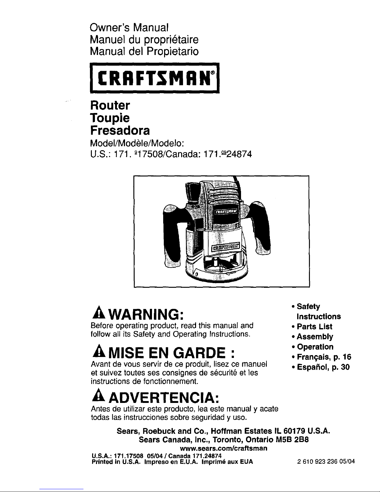
Router
Toupie
Fresadora
Model/Modele/Modelo:
U.S.: 171. _17508/Canada: 171._a24874
_kWARNING:
Before operating product, read this manual and
follow all its Safety and Operating Instructions.
-AMISE EN GARDE :
Avant de vous servir de ce produit, lisez ce manuel
et suivez toutes ses consignes de s_curit_ et les
instructions de fonctionnement.
-AADVERTENCIA:
Antes de utilizar este producto, lea este manual y acate
todas las instrucciones sobre seguridad y uso.
• Safety
Instructions
• Parts List
• Assembly
• Operation
• Frangais, p. 16
• Espafiol, p. 30
Sears, Roebuck and Co., Hoffman Estates IL 60179 U.S.A.
Sears Canada, Inc., Toronto, Ontario M5B 2B8
www.sears.com/craftsman
U.S.A.: 171.17508 05/04 / Canada 171.24874
Printed in U.S.A. Impreso en E.U.A. Imprimd aux EUA 2 610 923 236 05/04
/ONE YEAR FULL WARRANTY
If any part of this Craftsman Router is defective in material or workmanship within one year
from the date of purchase, return it to your nearest Sears Parts & Repair Center, and it will
be repaired or replaced free of charge.
WARRANTY SERVICE IS AVAILABLE BY CONTACTING SEARS SERVICE
AT 1-800-4-MY-HOME. ®
This warranty gives you specific legal rights, and you may also have other rights which
vary from state to state.
Sears Roebuck and Co. Dept. 817 WA Hoffman Estates, IL 60179
J
General Safety Instructions for Power Tools ................ 2, 3
Additional Safety Rules for Reuters ....................... 4-6
Functional Description, Specifications, and Parts List ........... 7, 8
Assembly ........................................... 9, 10
Operation .......................................... 11-14
Maintenance ........................................... 15
I __WARNING _Read and understand the tool manual and these instructions. Failure
I
to follow all instructions listed below may resutt in serious personal injury.
Work Area
Keep your work area clean and well lit.
Cluttered benches and dark areas invite
accidents.
Do not operate power tools in explosive
atmospheres, such as in the presence of
flammable liquids, gases, or dust. Power
tools create sparks that may ignite the dust
or fumes.
Keep bystanders, children, and visitors
away while operating a power tool.
Distractions can cause you to lose control.
Electrical Safety
Double Insulated tools are equipped with
a polarized plug (one b=ade is wider +"--,,,=,,
the other.) This plug will fit in a polarized
outlet only one way. If the plug does not fit
fully In the outlet, reverse the plug. If it still
does not fit, contact a qualified electrician
to install a polarized outlet. Do not change
the plug in any way. Double Insulation []
eliminates the need for the three wire
grounded power cord and grounded power
supply system.
Before plugging in the tool, be certain the
outlet voltage supplied is within the
voltage marked on the nameplate. Do not
use "AC only" rated tools with a DC power
supply.
Avoid body contact with grounded
surfaces such as pipes, radiators, ranges
and refrigerators. There is an increased risk
of electric shock if your body is grounded.
If operating the power tool in damp locations
is unavoidable, a Ground Fault Circuit
Interrupter must be used to supply the power
to your tool. Electrician's rubber gloves and
footwear will further enhance your personal
safety.
Don't expose power tools to rain or wet
conditions. Water entering a power tool will
increase the risk of electric shock.
Do not abuse ihe uord. Ne_er use the cord
to carry the tools or pull the plug from an
outlet. Keep cord away from heat, off,
sharp edges or moving parts. Replace
damaged cords immediately. Damaged
cords increase the risk of electric shock.
When operating a power tool outside, use
an outdoor extension cord marked "W-A"
or "W." These cords are rated for outdoor
use and reduce the risk of electric shock.
Refer to "Important Information about
Extension Cords".
2
Personal Safety
Stay alert, watch what you are doing and
use common sense when operating a
power tool. Do not use tool while tired or
under the influence of drugs, alcohol, or
medication. A moment of inattention while
operating power tools may result in serious
personal injury.
Dress properly. Do not wear loose clothing
or jewelry. Contain long hair. Keep your
hair, clothing, and gloves away from
moving parts. Loose clothes, jewelry, or
long hair can be caught in moving parts.
Keep handles dry, clean and free from oil
and grease.
Avoid accidental starting. Be sure switch
Is "OFF" before plugging In. Carrying tools
with your finger on the switch or plugging
in tools that have the switch "ON" invites
accidents.
Remove adjusting keys or wrenches
before turning the tool "ON". A wrench or a
key that is left attached to a rotating part of
the tool may result inpersonal injury.
Do not overreach. Keep proper footing
and balance at all times. Proper footing and
balance enables better control of the tool in
unexpected situations.
Usa safety goggles (head protection).
Wear safety goggles (must comply with ANSI
Standard Z87.1) at all times. Wear non-slip
footwear and a hard hat, if appropriate. Also,
use face or dust mask ifcutting operation is
dusty, and ear protectors (plugs or muffs)
during extended periods of operation.
Tool Use and Care
Use clamps or other practical way to
secure and support the workpiece to a
stable platform. Holding the work by hand
or against your body is unstable and may lead
to loss of control.
Do not force tool. Use the correct tool for
your application. The correct tool will do the
job better and safer at the rate for which it is
designed.
Do not use tool if switch does not turn It
"ON" or "OFF". Any tool that cannot be
controlled with the switch is dangerous and
must be repaired.
Disconnect the plug from the power
source before making any adjustments,
changing accessories, or storing the tool.
Such preventive safety measures reduce the
risk of starting the tool accidentally.
Keep guards In place. Maintain the guards in
working orderand in proper adjustment and
alignment.
3
Store idle tools out of reach of children
and other untrained parsons. Tools are
dangerous in the hands of untrained users.
Never leave tools running unattended.
Turn the power OFF. DO NOT leave tool
until it comes to a complete stop.
Maintain tools with care. Keep cutting
tools sharp and clean. Properly maintained
tools with sharp cutting edges are less likely
to bindand are easier to control. Any
alteration or modification is a misuse
and may result in a dangerous condition,
Check for damaged guards or parts,
misalignment or binding of moving parts,
breakage of parts, and any other eoedltlon
that may affect the tool's operation. If
damaged, have the tool properly repaired
or replaced before using. Many accidents
are caused by poorly maintained tools.
Develop a periodic maintenance schedule
for your tool.
Use only accessories that are
recommended by the manufacturer
for your model. Accessories that may
be suitable for one tool may become
hazardous when used on another tool.
Service
Tool service must be performed only
by qualified repair personnel. Service or
maintenance performed by unqualified
personnel could result in a risk of injury. For
example: internal wires may be misplaced or
pinched, safety guard return springs may be
improperly mounted.
When servicing a tool, use only Identical
replacement parts. Use of unauthorized
parts or failure to follow Maintenance
Instructionsmay create a risk of electric
shock or injury. Certain cleaning agents such
as gasoline, carbon tetrachloride, ammonia,
etc. may damage plastic parts.
Holdtoolby insulatedgrippingsurfaces
whenperforminganoperationwherethe
cuttingtool maycontacthiddenwiringor
itsowncord.Contactwitha"live" wire will
make exposed metal parts of the tool "live"
and shock the operator. If cutting into existing
walls or other blind areas where electrical
wiring may exist is unavoidable, disconnect all
fuses or circuit breakers feeding this worksite.
Always make sure the work surface is free
from nails and other foreign objects.
Cutting into a nail can cause the bit and the
tool to jump and damage the bit.
Never hold the workpiece in one hand and
the tool in the other hand when in use.
Never place hands near or below cutting
surface. Clamping the material and guiding
the tool with both hands is safer.
Never lay workpisce on top of hard
surfaces, like concrete, stone, etc...
Protruding cutting bit may cause tool to jump.
Always wear safety goggles and dust
mask. Use only In well ventilated area.
Using personal safety devices and working in
safe environment reduces risk of injury.
After changing the bits or making any
adjustments, make sure the collet nut and
any other adjustment devices are securely
tightened. Loose adjustment device can
unexpectedly shift, causing loss of control;
loose rotating components will be violently
thrown.
Never start the tool when the bit is
engaged in the material. The bit cutting
edge may grab the material, causing loss of
control of the cutter.
Always hold the tool with two hands
during start-up. The reaction torque of the
motor can cause the tool to twist.
The direction of feeding the bit into the
material is very important and it relates to
the direction of bit rotation. When viewing
the tool from the top, the bit rotates
clockwise. Feed direction of cutting
must be counter-clockwise. NOTE: inside
and outside cuts will require different feed
direction, refer to section on feeding the
router. Feeding the tool in the wrong direction
causes the cutting edge of the bit to climb out
of the work and pull the tool in the direction of
this feed.
Never use dull or damaged bits. Sharp bits
must be handled with care. Damaged bits
can snap dudng use. Dull bits require more
force to push the tool, possibly causing the bit
to break.
Never touch the bit during or Immediately
after the use. After use, the bit is too hot to
be touched by bare hands.
Never lay the tool down until the motor
has come to a complete standstill. The
spinning bit can grab the surface and pull
the tool out of your control.
Never use bits that have a cutting diameter
greater than the opening in the base.
LAWARNINGJSome dust
created by power sanding, sawing,
grinding, drilling, and other construction
activities contains chemicals known to
cause cancer, birth defects or other
reproductive harm. Some examples
of these chemicals are:
• Lead from lead-based paints,
• Crystalline silica from bricks and cement and
other masonry products, and
•Arsenic and chromium from chemically-
treated lumber.
Your risk from these exposures varies,
depending on how often you do this type of
work. To reduce your exposure to these
chemicals: work in a well ventilated area, and
work with approved safety equipment, such
as those dust masks that are specially
designed to filter out microscopic particles.

[ _)_WARNING n If an extension cord is necessary, a cord with adequate size
I
conductors that is capable of carrying the current necessary for your tool must be used,
This will prevent excessive voltage drop, loss of power or overheating. Grounded tools must
use 3-wire extension cords that have 3-prong plugs and receptacles.
NOTE: The smaller the gauge number,the heavier the cord.
RECOMMENDED SIZES OF EXTENSION CORDS
120 VOLT ALTERNATING CURRENT TOOLS
Tool's
Ampere
Rating
3-6
6-8
8-10
10-12
12-16
Cord SizeinA.W.G. WireSizesin mm2
CordLengthInFeet Cord LengthIn Meters
25 50 100 150 15 30 60 120
18 16 16 14
18 16 14 12
18 16 14 12
16 16 14 12
14 12
.75 .75 1.5 2.5
.75 1.0 2.5 4.0
.75 1.0 2.5 4.0
1.0 2.5 4.0 --
- SAVE THESE INSTRUCTIONS -
(_ This symbol designates
that thistool is listed by
Underwriters Laboratories.
This symbol designates that this
p.| U| J tool is listed to Canadian Standards
" _ by Underwriters Laboratories.
This symbol designates
that this tool is listed
by the Canadian
Standards Association.
This symbol designates that this
tool is listed by Underwriters
Laboratories, and listed to
Canadian Standards by
Underwriters Laboratories.
I
NOM-
This symbol designates
that this toolcomplies to
NOM Mexican Standards.
5

IMPORTANT" Some of the following symbols may be used on your tool. Please study them
and learn their meaning. Proper interpretation of these symbols will allow you to operate the tool
Symbol
V
A
Hz
W
rain
S
0
better and safer.
Name
Volts
Amperes
Hertz
Watt
Kilograms
Minutes
Seconds
Diameter
no
...Imin
o
1,2,3 ....
I, II, lU,
_mm
[]
No load speed
Revolutions or reciprocation
_er minute
Off position
Selector settings
Infinitely variable selector with off
Arrow
Alternating current
Direct current
Alternating or direct current
Class II construction
Earthing terminal
Warning symbol
Ni-Cad RBRC seal
Designation/Explanation
Voltage (potential)
Current
Frequency (cycles per second)
Power
Weight
_me
13me
Size ofdrill bits, grindingwheels,
etc.
Rotational speed, at no load
Revolutions, strokes, surface
speed, orbits, etc. per minute
Zero speed, zero torque...
Speed, torque or positionsettings
Higher number means greater
speed
Speed is increasing from 0 setting
Action in the direction of arrow
Type or a characteristic of current
Type or a characteristic of current
Type or a characteristicof current
Designates Double Insulated
Construction tools
Grounding terminal
Alerts user to warning messages
Designates Ni-Cad battery
recyclingprogram
6
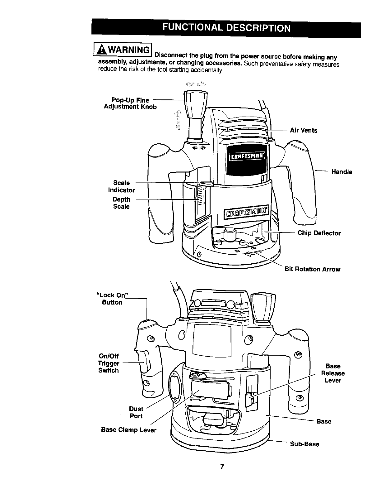
[ WARNING I Disconnect the plug from the power source before making any
I
assembly, adjustments, or changing accessories, Such preventative safety measures
reduce the risk of the tool starting accidentally.
Pop-Up Fine
Adjustment Knob
Vents
Scale
Indicator
Depth
Scale
Handle
Chip Deflector
Bit Rotation Arrow
"Lock On"
Button
On/Off
Trigger
Switch
Base
Release
Lever
Dust
Port
Base Clamp Lever
Base
Sub-Base
7
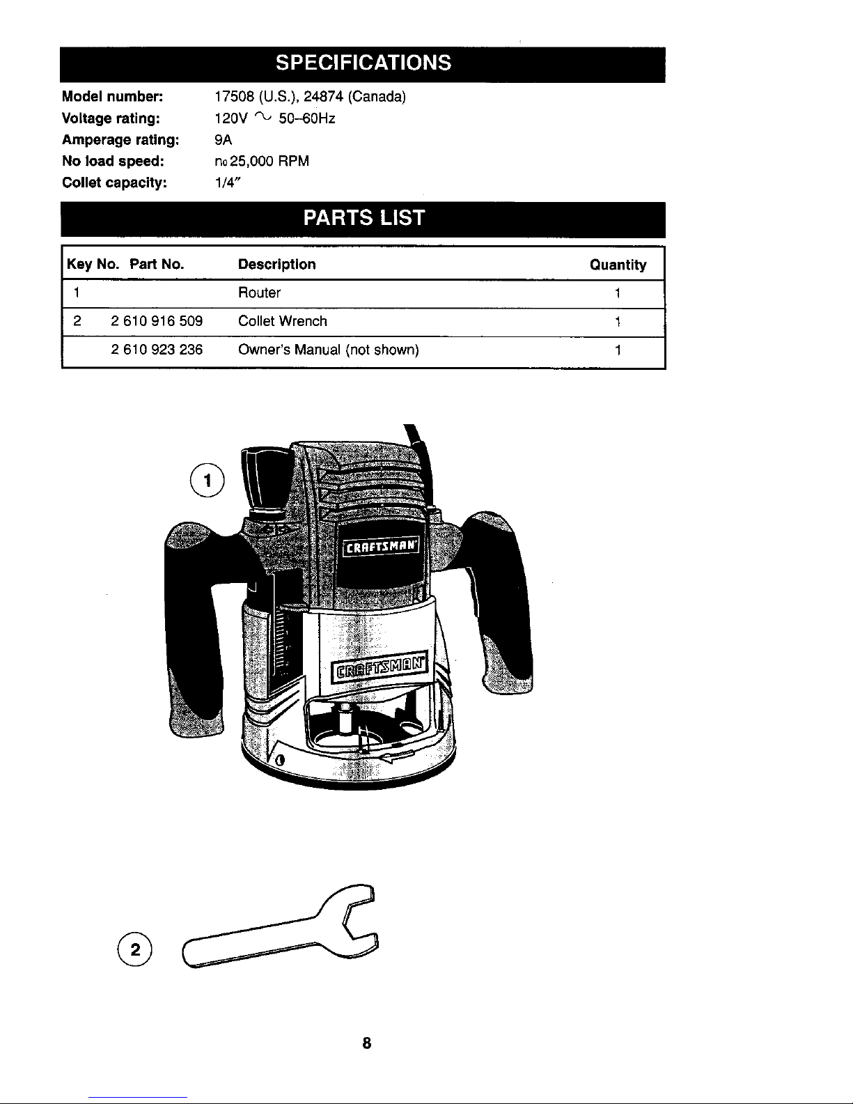
Modelnumber:
Voltagerating:
Amperagerating:
Noloadspeed:
Colletcapaclty:
17508 (U.S.), 24874 (Canada)
120V _ 50-60Hz
9A
no25,000 RPM
1/4"
Key No. Part No. Description Quantity
1 Router 1
2 2 610 916 509 Collet Wrench 1
2 610 923 236 Owner's Manual (not shown) 1
@
8
A wide assortment of router bits with
different profiles is available separately.
I __WARNINGj Topreventpersonal
injury, always remove the plug from
power source before removing or
installing bits or accessories.
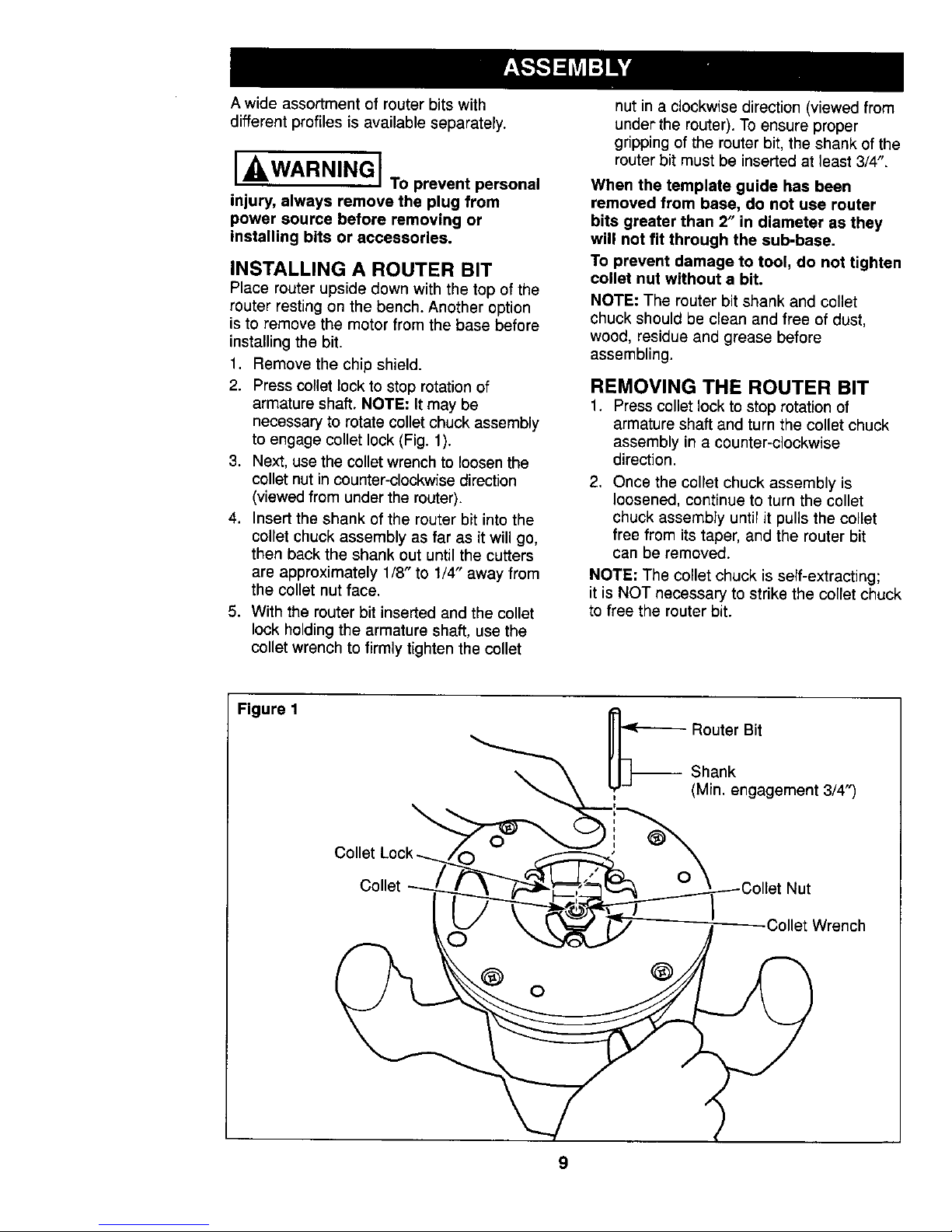
INSTALLING A ROUTER BIT
Place router upside down with the top of the
router resting on the bench. Another option
is to remove the motor from the base before
installing the bit.
1. Remove the chip shield.
2. Press collet lock to stop rotation of
armature shaft. NOTE: It may be
necessary to rotate collet chuck assembly
to engage collet lock (Fig. 1).
3. Next, use the collet wrench to loosen the
collet nut in counter-clockwise direction
(viewed from under the router).
4. Insert the shank of the router bit into the
collet chuck assembly as far as it will go,
then back the shank out until the cutters
are approximately 1/8" to 1/4" away from
the collet nut face.
5. With the router bit inserted and the collet
lock holding the armature shaft, use the
collet wrench to firmly tighten the collet
nut in a clockwise direction (viewed from
under the router). To ensure proper
gripping of the router bit, the shank of the
router bit must be inserted at least 3/4".
When the template guide has been
removed from base, do not use router
bits greater than 2" in diameter as they
will not fit through the sub-base.
To prevent damage to tool, do not tighten
collet nut without a bit.
NOTE: The router bit shank and collet
chuck should be clean and free of dust,
wood, residue and grease before
assembling.
REMOVING THE ROUTER BIT
1. Press collet lock to stop rotation of
armature shaft and turn the collet chuck
assembly in a counter-clockwise
direction.
.
Once the collet chuck assembly is
loosened, continue to turn the collet
chuck assembly until it pulis the collet
free from its taper, and the router bit
can be removed.
NOTE: The collet chuck is self-extracting;
it is NOT necessary to strike the collet chuck
to free the router bit.
Figure 1
\
,_ Router Bit
Shank
(Min. engagement 3/4")
Colle
,_tWrench
®
9
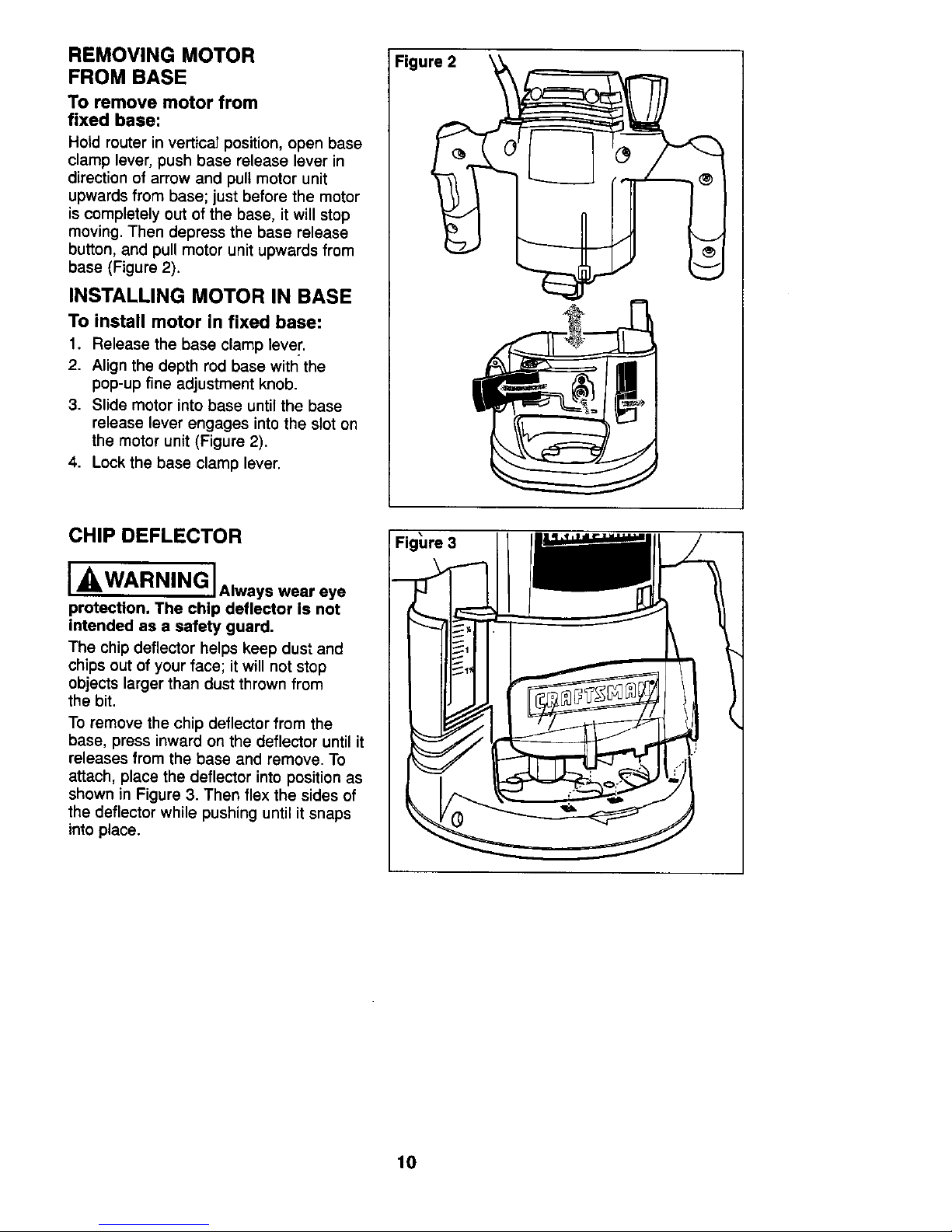
REMOVING MOTOR
FROM BASE
To remove motor from
fixed base:
Hold router in vertical position, open base
clamp lever, push base release lever in
direction of arrow and pull motor unit
upwards from base; just before the motor
is completely out of the base, it will stop
moving. Then depress the base release
button, and pull motor unit upwards from
base (Figure 2).
INSTALLING MOTOR IN BASE
To install motor in fixed base:
1. Release the base clamp lever.
2. Align the depth rod base with the
pop-up fine adjustment knob.
3. Slide motor into base until the base
release lever engages into the slot on
the motor unit (Figure 2).
4. Lock the base clamp lever.
CHIP DEFLECTOR
I_WARNING IAIwayswear eye
protection. The chip deflector is not
intended as a safety guard.
The chip deflector helps keep dust and
chips out of your face; it will not stop
objects larger than dust thrown from
the bit.
To remove the chip deflector from the
base, press inward on the deflector until it
releases from the base and remove. To
attach, place the deflector into position as
shown in Figure 3. Then flex the sides of
the deflector while pushing until it snaps
into place.
Figure 3
!
10
Craftsman reuters are designed for speed,
accuracy and convenience in performing
cabinet work, routing, fluting, beading,
cove-cutting, dovetails, etc. They will
enable you to accomplish inlay work,
decorative edges and many types of
special carving.
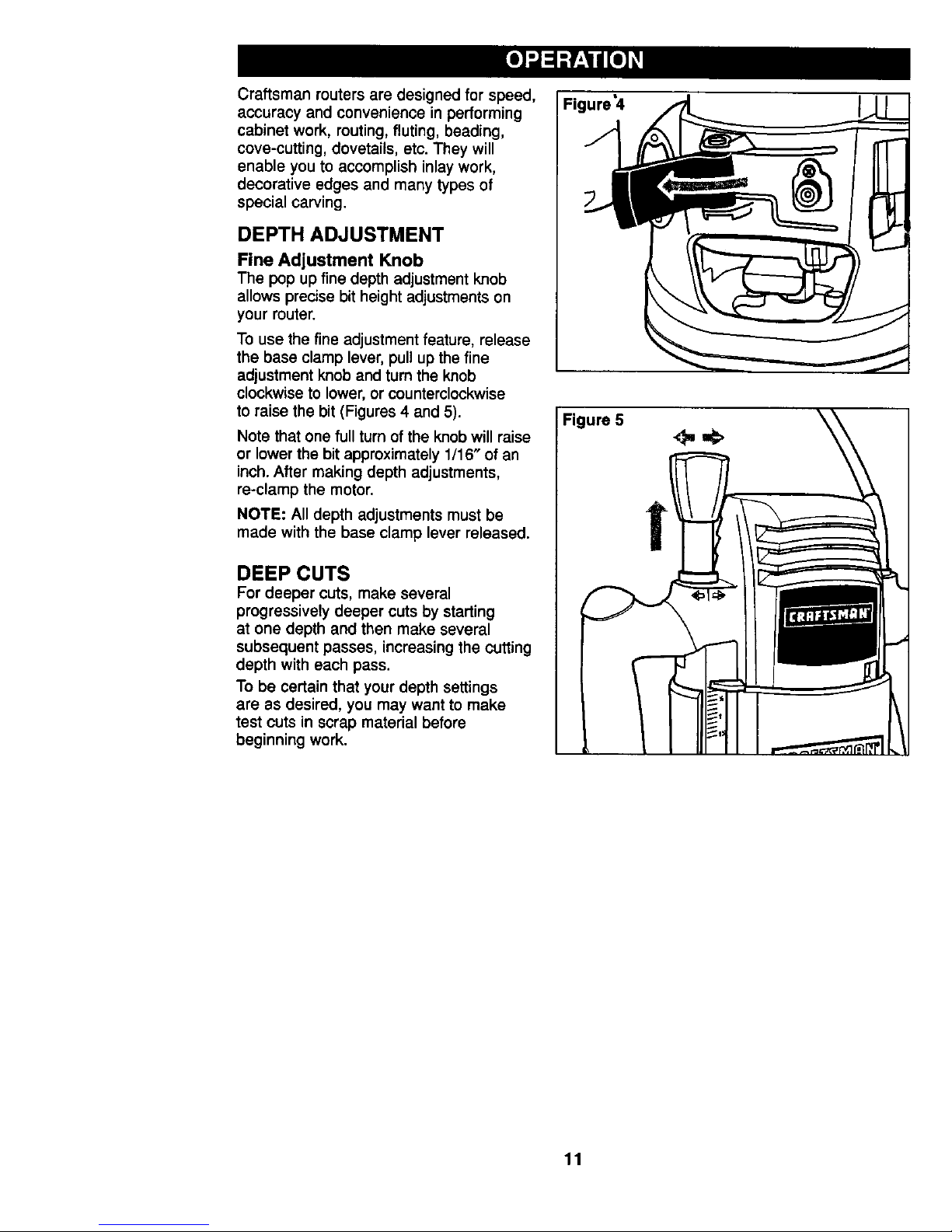
DEPTH ADJUSTMENT
Fine Adjustment Knob
The pop up fine depth adjustment knob
allows precise bit height adjustments on
your router.
To use the fine adjustment feature, release
the base clamp lever, pull up the fine
adjustment knob and turn the knob
clockwise to lower, or counterclockwise
to raise the bit (Figures 4 and 5).
Note that one full turn of the knob will raise
or lower the bit approximately 1/16" of an
inch. After making depth adjustments,
re-clamp the motor.
NOTE: All depth adjustments must be
made with the base clamp lever released.
DEEP CUTS
For deeper cuts, make several
progressively deeper cuts by starting
at one depth and then make several
subsequent passes, increasing the cutting
depth with each pass.
To be certain that your depth settings
are as desired, you may want to make
test cuts in scrap material before
beginning work.
Figure'4
Figure 5
!
L
\
.I
11
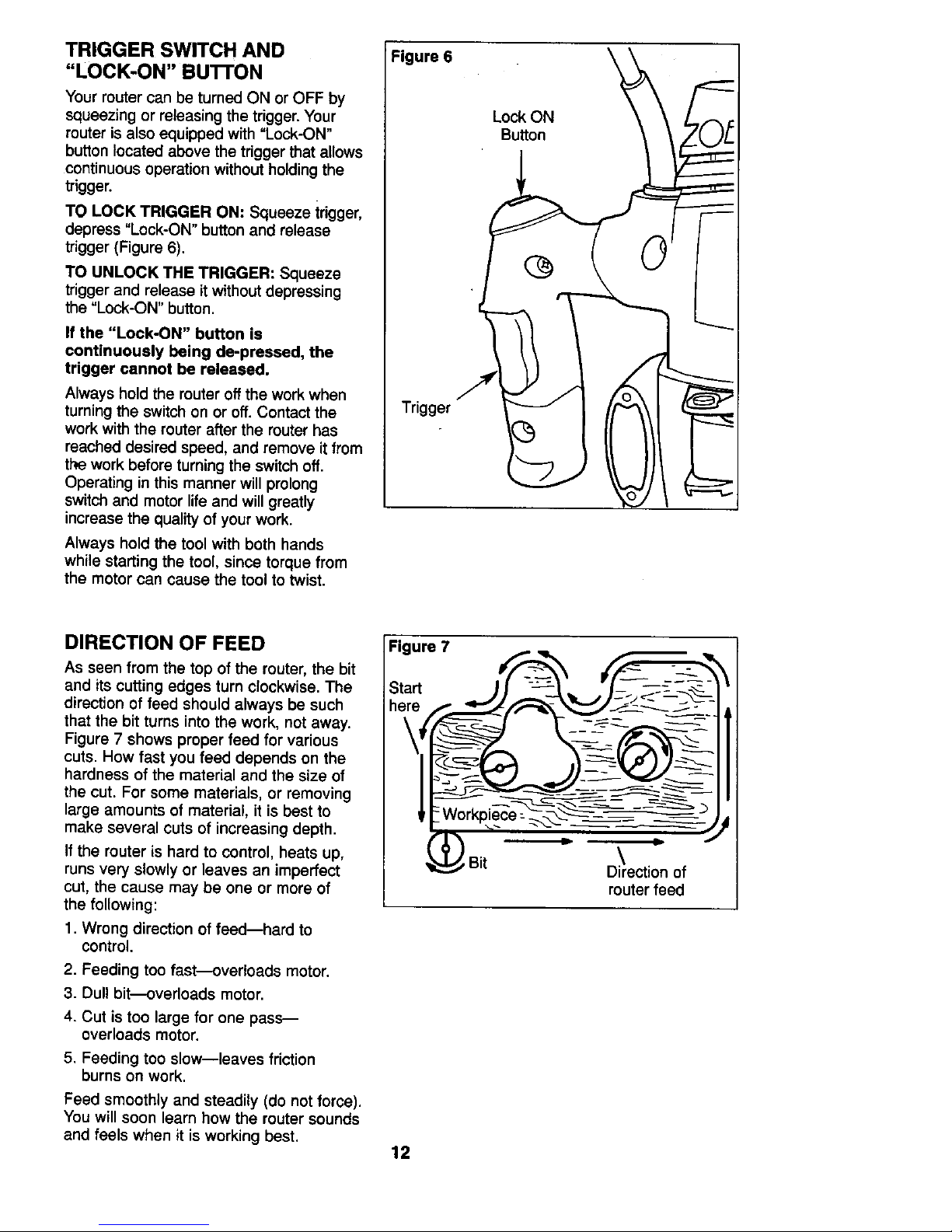
TRIGGER SWITCH AND
"LOCK-ON" Bu'n'ON
Your router can be turned ON or OFF by
squeezing or releasing the trigger. Your
router is also equipped with "Lock-ON"
button located above the trigger that allows
continuous operation without holding the
trigger.
TO LOCK TRIGGER ON: Squeeze trigger,
depress "Lock-ON" button and release
trigger (Figure 6).
TO UNLOCK THE TRIGGER: Squeeze
trigger and release it without depressing
the "Lock-ON" button.
If the "Lock-ON" button is
continuously being de-pressed, the
trigger cannot be released.
Always hold the router off the work when
turning the switch on or off. Contact the
work with the router after the router has
reached desired speed, and remove it from
the work before turning the switch off.
Operating in this manner will prolong
switch and motor life and will greatly
increase the quality of your work.
Always hold the tool with both hands
while starting the tool, since torque from
the motor can cause the tool to twist.
Figure 6
Lock ON
Button
Trigger
\
DIRECTION OF FEED
As seen from the top of the router, the bit
and its cutting edges turn clockwise. The
direction of feed should always be such
that the bit turns into the work, not away.
Figure 7 shows proper feed for various
cuts. How fast you feed depends on the
hardness of the material and the size of
the cut. For some materials, or removing
large amounts of material, it is best to
make several cuts of increasing depth.
If the router is hard to control, heats up,
runs very slowly or leaves an imperfect
cut, the cause may be one or more of
the following:
1. Wrong direction of feed--hard to
control.
2. Feeding too fast---overloads motor.
3. Dull bit---overloads motor.
4. Cut is too large for one pass--
overloads motor.
5. Feeding too slow--leaves friction
burns on work.
Feed smoothly and steadily (do not force).
You will soon learn how the router sounds
and feels when it is working best.
Figure 7
Start
12
!Bit
\
Direction of
router feed
RATE OF FEED
Feed the router at a moderate rate. When
routing or doing related work in wood and
plastics, the best results will occur if the
depth of cut and feed rate are regulated
to keep the motor operating at high
speed. Soft materials require a faster feed
rate than hard materials.
The router may stall if used improperly
or overloaded. Reduce the feed rate to
prevent possible damage to the tool.
Always be sure the collet chuck is
tightened securely before use.
Always use router bits with the shortest
cutting length necessary to produce the
desired cut. This will minimize router bit
run-out and chatter.
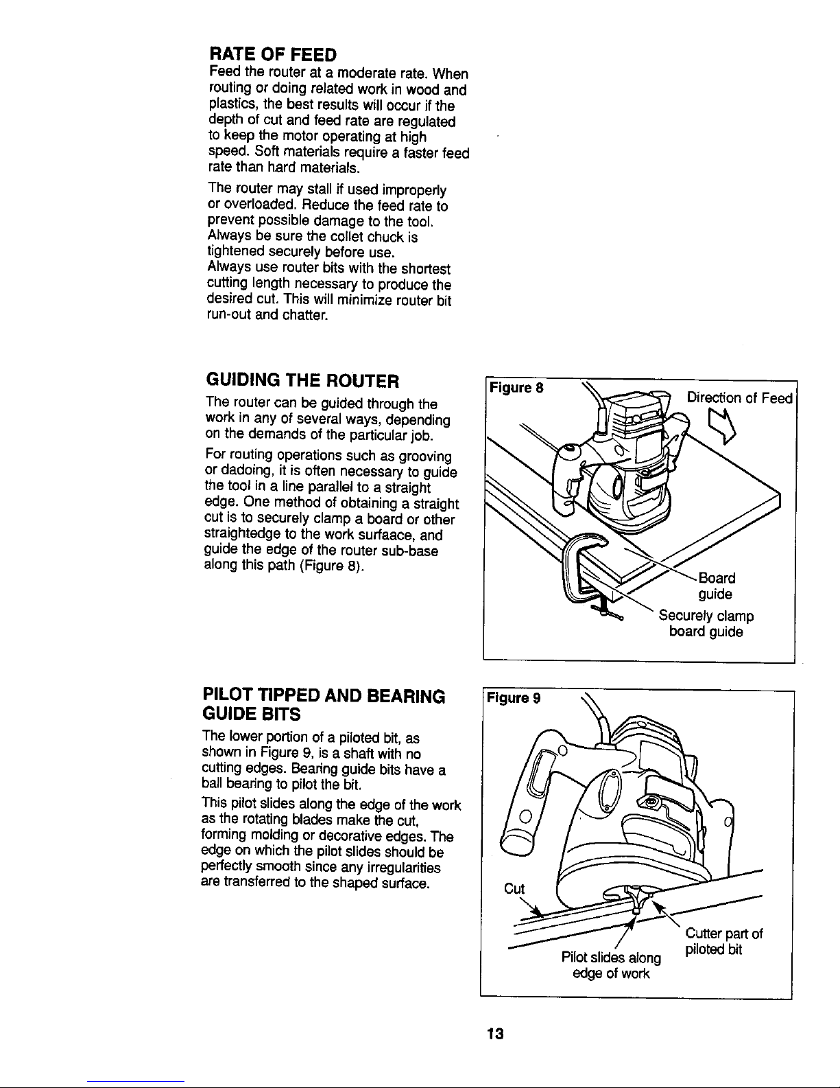
GUIDING THE ROUTER
The router can be guided through the
work in any of several ways, depending
on the demands ot the particular job.
For routing operations such as grooving
or dadoing, it is often necessary to guide
the tool in a line parallel to a straight
edge. One method of obtaining a straight
cut is to securely clamp a board or other
straightedge to the work surfaace, and
guide the edge of the router sub-base
along this path (Figure 8).
Figure 8
Direction of Feed
guide
clamp
board guide
PILOT TIPPED AND BEARING FI
GUIDE BITS
The lower portion of a piloted bit, as
shown in Figure 9, is a shaft with no
cutting edges. Beadng guide bits have a
ball beadng to pilot the bit.
This pilot slides along the edge of the work
as the rotating blades make the cut,
forming molding or decorative edges. The
edge on which the pilot slides should be
perfectly smooth since any irregularities
are transferred to the shaped surface. Cu__
__..1---_/_ Cutter part of
...... _ ..... piloted bit
I Pilot slioes aJong
l edge of work
13
TEMPLATES
Using template patterns lets you duplicate
designs or letters uniformly time after
time. This technique requires the use of
a template guide adapter and a template
guide.
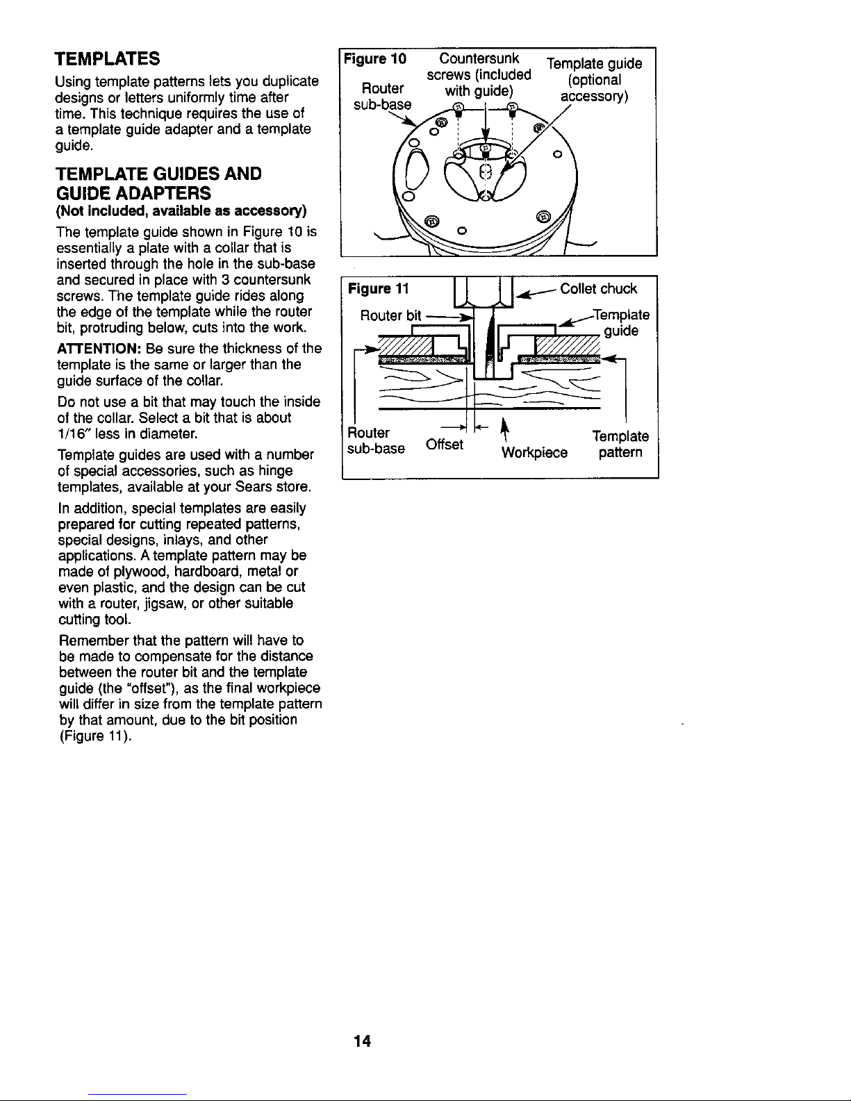
TEMPLATE GUIDES AND
GUIDE ADAPTERS
(Not included, available as accessory)
The template guide shown in Figure 10 is
essentially a plate with a collar that is
inserted through the hole in the sub-base
and secured in place with 3 countersunk
screws. The template guide rides along
the edge of the template while the router
bit, protruding below, cuts into the work.
ATTENTION: Be sure the thickness of the
template is the same or larger than the
guide surface of the collar.
Do not use a bit that may touch the inside
of the collar. Select a bit that is about
1/16" less in diameter.
Template guides are used with a number
of special accessories, such as hinge
templates, available at your Sears store.
In addition, special templates are easily
prepared for cutting repeated patterns,
special designs, inlays, and other
applications. A template pattern may be
made of plywood, hardboard, metal or
even plastic, and the design can be cut
with a router, jigsaw, or other suitable
cutting tool.
Remember that the pattern will have to
be made to compensate for the distance
between the router bit and the template
guide (the "offset"), as the final workpiece
will differ in size from the template pattern
by that amount, due to the bit position
(Figure 11).
Figure 10 Countersunk Template guide
screws (included (optional
Router with guide) accessory)
sub-base __._--t--.-_._ /
Figure 11 L_LJ.dp_-_ Collet chuck
Router bit -_ _ _..tTemptate
. 0u0e
14
€.ANING
,'!ARNING I Toavoid
accidents, always disconnect the tool
from the power supply before cleaning
or performing any maintenance.
Avoid using solvents when cleaning plastic
parts. Most plastics are susceptible to
damage from various types of commercial
solvents and may be damaged by their
use. Use a clean cloth to remove dirt,
dust, etc.
I_WARNINGIDo not at any time
allow brake fluids, gasoline, petroleum-
based products, penetrating oils, etc. to
come in contact with plastic parts. They
contain chemicals that can damage,
weaken or destroy plastic parts.
I WARNINGI Alwayswear
safety goggles with side shields during
power tool operation or when blowing
dust. If an operation is dusty, also wear
e dust mask. Failure to do so could result
in possible serious injury.
Electric tools used on fiberglass material,
wallboard, spackling compound, or plaster
are subject to accelerated wear and
possibly premature failure because the
fiberglass chips and grindings are highly
abrasive to bearings, brushes,
commutators, etc. As a result, we do not
recommend using this tool for extended
work with these types of materials.
However, if you do work with any of these
materials, it is extremely important to clean
the tool thoroughly with compressed air.
Ventilation openings and switch levers
must be kept clean and free of foreign
matter. Do not attempt to clean by
inserting pointed objects through
openings.
From t}me to time, the collet and toilet nut
should be cleaned. To do so, remove the
collet nut from the collet and remove any
accumulated dust and chips. Then reinstall
the collet nut to its original position.
SERVICE
iAWARN'NG]
When servicing, use only identical
Craftsman replacement parts. Use of
any other part may create a hazard or
cause product damage. We recommend
that all tool service be performed by a
Sears repair center.
Only the parts shown on the parts list are
intended to be repaired or replaced by the
customer. All other parts are an important
part of the double insulation system and
should be serviced only by a qualified
Sears service technician.
Cutters
Clean, sharp cutters provide faster and
more accurate cutting results. Remove
any accumulated pitch and gum from
cutters after each use.
When sharpening cutters, sharpen only
the inside of the cutting edge. NEVER
grind the outside diameter. When
sharpenening the end of a cutter, be
sure to grind the clearance angle the
same as it was originally ground.
Tool Lubrication
All bearings in this tool are lubricated with
a sufficient amount of high grade lubricant
for the life of the tool under normal
operating conditions. No further lubrication
is required.
15
 Loading...