

1619X01301
Owner's Manual
Manual del propietario
Manuel du proprietaire
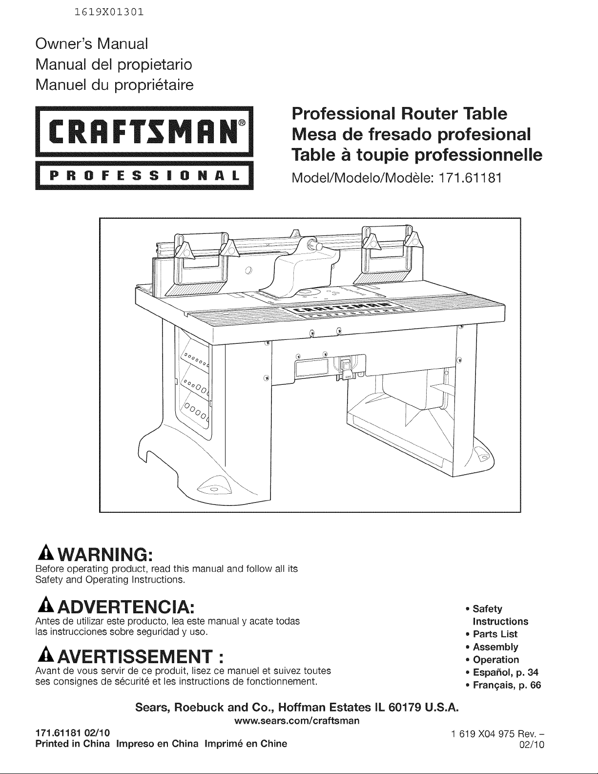
Professional Router Table
Mesa de fresado profesional
Table _ toupie professionnelle
Model/Modelo/Modele: 171.61181
@
@
-&WARNING:
Before operating product, read this manual and follow all its
Safety and Operating Instructions.
_ADVERTENCIA:
Antes de utilizar este producto, lea este manual y acate todas
las instrucciones sobre seguridad y uso.
-&AVERTISSEMENT :
Avant de vous servir de ce produit, lisez ce manuel et suivez toutes
ses consignes de securit6 et les instructions de fonctionnement.
• Safety
Instructions
• Parts List
• Assembly
• Operation
• Espa_ol, p. 34
• Frangais, p. 66
171.61181 02/10
Printed in China
Sears, Roebuck and Co., Hoffman Estates IL 60179 U.S.A.
www.sears.com/craftsman
1 619 X04 975 Rev. -
Impreso en China Imprim_ en Chine 02/10
f
! ONE-YEAR FULL WARRANTY ON CRAFTSMAN PROFESSIONAL TOOL
If this Craftsman tool fails due to a defect in material or workmanship within one year from the date
of purchase, CALL 1-800-4-MY-HOME _ TO ARRANGE FOR FREE REPAIR (or replacement if repair proves
impossible).
This warranty does not include expendable parts, such as lamps, batteries, bits or blades.
This warranty gives you specific legal rights, and you may also have other rights which vary
from state to state.
Sears, Roebuck and Co., Hoffman Estates, IL 60179 _j
iMPORTANT SAFETY iNFORMATiON . .. 2=6
Optional Router Table Accessories ...... 7
Router Table Assembly ............. 12-21
Router Table Operation ............ 22=33
Parts List ......................... 8-11
I-_ I Read and understand the tool manual and these instructions for the use of this table with
WARNING your router. Failure to follow all instructions listed below may result in serious personal injury.
SAVE THESE iNSTRUCTiONS
Work Area
Keep your work area clean and well lit. Cluttered
benches and dark areas invite accidents.
Do not operate power tools in explosive
atmospheres, such as in the presence of flammable
liquids, gases, or dust. Power tools create sparks which
may ignite the dust or fumes.
Keep bystanders, children, and visitors away while
operating a power tool. Distractions can cause you to
lose control.
Electrical Safety
Grounded tools must be plugged into an outlet
properly installed and grounded in accordance
with all codes and ordinances. Never remove the
grounding prong or modify the plug in any way. Do
not use any adaptor plugs. Check with a qualified
electrician if you are in doubt as to whether the outlet
is properly grounded, if the tools should electrically
malfunction or break down, grounding provides a low
resistance path to carry electricity away from the user.
Improper grounding can shock, burn, or electrocute.
Grounded tools are equipped with three-conductor cord
and three-prong type plugs. Before plugging in the tool,
be certain the outlet voltage suppfied is within the voltage
marked on the nameplate. Do not use "AC only" rated
tools with a DC power supply.
Double-insulated tools are equipped with a polarized
plug (one blade is wider than the other.) This plug will
fit in a polarized outlet only one way. If the plug does
not fit fully in the outlet, reverse the plug. If it still
does not fit, contact a qualified electrician to install a
polarized outlet. Do not change the plug in any way.
Double Insulation [] eliminates the need for the three-
wire grounded power cord and grounded power supply
system. Before plugging in the tool, be certain the outlet
voltage suppfied is within the voltage marked on the
nameplate. Do not use "AC only" rated tools with a DC
power supply.
Avoid body contact with grounded surfaces such
as pipes, radiators, ranges, and refrigerators.
There is an increased risk of electric shock if your body is
grounded, if operating the power tool in damp locations
is unavoidable, a Ground Fault Circuit interrupter must be
used to supply the power to your tool. Electricians'
rubber gloves and footwear will further enhance
your personal safety.
Don't expose power tools to rain or wet conditions.
Water entering a power tool will increase the risk of
electric shock.
Do not abuse the cord. Never use the cord to carry
the tools or pull the plug from an outlet. Keep cord
away from heat, oil, sharp edges, or moving parts.
Replace damaged cords immediately. Damaged cords
increase the risk of electric shock.
When operating a power tool outside, use an outdoor
extension cord marked "W-A" or "W." These cords are
rated for outdoor use and reduce the risk of electric
shock. Refer to "important information About Extension
Cords" in your router table manual.
Personal Safety
Stay alert, watch what you are doing, and use
common sense when operating a power tool.
Do not use tool while tired or under the influence
of drugs, alcohol, or medication. A moment of
inattention while operating power tools may result
in serious personal injury.
Keep guards in place. Maintain the guards in working
order and in proper adjustment and alignment.
Avoid accidental starting. Be sure switch is "OFF"
before plugging in. Carrying tools with your finger on
the switch or plugging in tools that have the switch "ON"
invites accidents.
Remove adjusting keys or wrenches before turning
the tool "ON." A wrench or a key that is left attached to
a rotating part of the tool may result in personal injury.
Do not overreach. Keep proper footing and balance
at all times. Proper footing and balance enable better
control of the tool in unexpected situations.
Use safety goggles (head protection). Wear safety
goggles (must comply with ANSI Standard Z87.1) at
all times. Wear non-slip footwear and a hard hat, if
appropriate. Also, use face or dust mask if cutting
operation is dusty and ear protectors (plugs or muffs)
during extended periods of operation.
Tool Use and Care
Use clamps or other practical way to secure and
support the workpiece to a stable platform. Holding
the work by hand or against your body is unstable and
may lead to loss of control.
Do not force tool. Use the correct tool for your
application. The correct tool will do the job better and
safer at the rate for which it is designed.
Do not use tool if switch does not turn it "ON" or
"OFF." Any tool that cannot be controlled with the switch
is dangerous and must be repaired.
Disconnect the plug from the power source before
making any adjustments, changing accessories, or
storing the tool. Such preventive safety measures
reduce the risk of starting the tool accidentally.
Keep guards in place. Maintain the guards in working
order and in proper adjustment and alignment.
Store idle tools out of reach of children and other
untrained persons. Tools are dangerous in the hands
of untrained users.
Never leave tools running unattended. Turn the
power OFF. DO NOT leave tool until it comes to a
complete stop.
Maintain tools with care. Keep cutting tools sharp
and clean. Properly maintained tools, with sharp cutting
edges, are less likely to bind and are easier to control.
Any alteration or modification is a misuse and may result
in a dangerous condition.
Check for damaged guards or parts, misalignment, or
binding of moving parts, breakage of parts, and any
other condition that may affect the tool's operation, if
damaged, have the tool properly repaired or replaced
before using. Many accidents are caused by poorly
maintained tools. Develop a periodic maintenance
schedule for your tool.
Use only accessories that are recommended by the
manufacturer for your model. Accessories that may be
suitable for one tool may become hazardous when used
on another tool.
Service
Tool service must be performed only by qualified
repair personnel. Service or maintenance performed by
unqualified personnel could result in a risk of injury. For
example: internal wires may be misplaced or pinched;
safety guard return springs may be improperly mounted.
When servicing a tool, use only identical replacement
parts. Use of unauthorized parts or failure to follow
maintenance instructions may create a risk of electric
shock or injury. Certain cleaning agents such as gasoline,
carbon tetrachloride, and ammonia may damage
plastic parts.
Lift router table only by the table edges. Lifting table by any other
surface could cause personal injury.
Do not use the router table until all assembly and installation
steps have been completed. Prior to each use, verify that
fasteners and the router clamps are tight. A loose table or router
is unstable and may shift in use, resulting in property damage or
serious personal injury.
Disconnect the router from the power supply before installing
router into the table, making adjustments, changing
accessories, removing the router from the table, performing
maintenance, or storing the tool. Such precautionary safety
measures reduce the risk of unintentional tool operation.
Do not plug router motor power cord into standard wall
outlet. Always plug router cord into the router table switch box.
Power tool switches and controls need to be within your reach in
emergency situations.
Do not permit fingers to touch terminals on the plug when
inserting or removing plug from the outlet. Risk of Electric Shock.
Before connecting router or vacuum to router table switch box,
ensure that the router or vacuum switch is off and that the
router table switch box is unplugged. Such precautionary safety
measures reduce the risk of unintentional tool operation.
Before using the router table, verify that the router is securely
clamped to the router table base. While working, periodically
check the router base fastener clamping tightness. Vibrations
from cutting operations can cause router motor clamps to loosen
and the router motor may fall from the table.
Before starting to work, ensure that the power cords from the
router accessories, the switch box, and the extension cord do
not and cannot come in contact with the router or any moving
parts of the router. Such precautionary safety measures reduce
the risk of injury due to loss of control.
Do not use the router table without the overhead guard
unless required by a particular cutting operation. Replace guard
immediately after completion of cutting operation. Remove all
dust, chips, and any other foreign particles that can affect its
function. The guard will aid in keeping hands from unintended
contact with the rotating bit.
Do not use bits that have a cutting diameter that exceeds
the clearance hole in the tabletop insert plate or insert rings.
The bit could contact the insert plate or insert ring, throwing
fragments.
Never use dull or damaged bits. Damaged bits can snap during
use. Dull bits require more force to push the workpiece, possibly
causing the bit to break or the material to kick back.
Handle sharp bits with care. Such precautionary safety measures
reduce risk of injury.
Do not alter insert ring or insert plate bit hole. Match the cutting
diameter of the bit to the inner diameter of the insert ring or
insert plate bit hole such that the difference is no less than
1/16 in. on a side. Insert rings are meant to reduce the gap between
the cutting diameter of the bit and the table so that workpieces
maintain full support of the table while routing.
Install bit in accordance with instructions in the router manual.
Securely clamp the router bit in the collet chuck before making
any cuts. Securing the bit before cutting reduces the risk of the bit
becoming loose during operation.
Never place your fingers near a spinning bit or under the guard
when the router is plugged in. Such precautionary safety measures
reduce the risk of injury.
Never hold the workpiece on the outfeed side of the bit. Pressing
the workpiece against the outfeed side of the fence may cause
material binding and possible kickback, pulling your hand into
the bit.
Guide the workpiece with the fence to maintain control of the
workpiece. Do not place the workpiece between the router bit
and fence while routing the edge. This placement will cause the
material to become wedged, making kickback possible.
Only use routers for working with wood, woodlike products,
plastic, or laminates. Do not use router and router table for
cutting or shaping metals. Be sure workpiece does not contain
nails or other hard objects. Cutting nails may cause loss of control
of the tool or workpiece.
Never start the tool when the bit is engaged in the material. The
bit-cutting edge may grab the material, causing loss of control of the
workpiece.
Feed the workpiece only against the rotation of the bit.
Do not "back feed" the workpiece into the bit. The bit rotates
counterclockwise as viewed from the top of the table. "Back
feeding" will cause the workpiece to "climb" up on the bit, pulling
the workpiece and possibly your hands into the rotating bit.
Do not feed the workpiece into the bit where the majority of the
workpiece is between the fence and the bit. This creates a "fence
trap" which is a hazardous situation due to the bit being exposed.
This will cause the work to "climb-cut" away from the tabletop and
may lead to loss of control during operation.
Do not cut material that is warped, wobbly, or otherwise
unstable. The router table is designed to cut fiat, straight,
and squared materials. If the material is slightly curved but
otherwise stable, cut the material with the concave side against
the table or fence. Cutting the material with the concave side up or
away from the table may cause the warped or wobbly material to roll
and kick back, causing the user to lose control.
Use auxiliary infeed and outfeed supports for long or wide
workpieces. Oversize workpieces without adequate support can flip
off the table or cause the table to tip.
Use push stick, vertically and horizontally mounted
featherboards (spring sticks), and other jigs to hold down the
workpiece. Push sticks, featherboards, and jigs eliminate the need
to hold the workpiece near the spinning bit.
Never let go of the workpiece when routing until the cut has
been completed and the workpiece is completely dear of the
bit. Such precautionary safety measures reduce the risk of injury
and property damage. Featherboards aid in holding the workpiece
in position when routing on a router table. They are not intended to
hold the workpiece in place alone when the workpiece is in contact
with the bit, or at any other time when the bit is turning.
Always hold the workpiece against the router table fence when
routing. Such precautionary measures increase accuracy in routing
and improve control of the workpiece, reducing the risk of injury.
Never leave the router unattended while it is running or before
it comes to a complete stop. Such precautionary safety measures
reduce the risk of injury and property damage.
Do not use the table as a workbench or work surface. Using it for
purposes other than routing may cause damage and make it unsafe
to use in routing.
Never stand on the table or use as a ladder or scaffolding.
The table could tip or the cutting tool could be accidentally
contacted.
When servicing the tool, use only recommended CRAFTSMAN
replacement parts. Follow instructions in the Maintenance
section of this manual Use of unauthorized parts or failure to
follow maintenance instructions can result in personal injury.
Some dust created by power sanding, sawing, grinding, drilling,
and other construction activities contains chemicals known to
cause cancer, birth defects, or other reproductive harm. Some
examples of these chemicals are:
• Lead from lead-based paints
• Crystalline silica from bricks, cement, and other masonry products
• Arsenic and chromium from chemically treated lumber
Your risk from these exposures varies, depending on how often you
do this type of work. To reduce your exposure to these chemicals,
work in a well-ventilated area, and work with approved safety
equipment, such as those dust masks that are specially designed
to filter out microscopic particles.
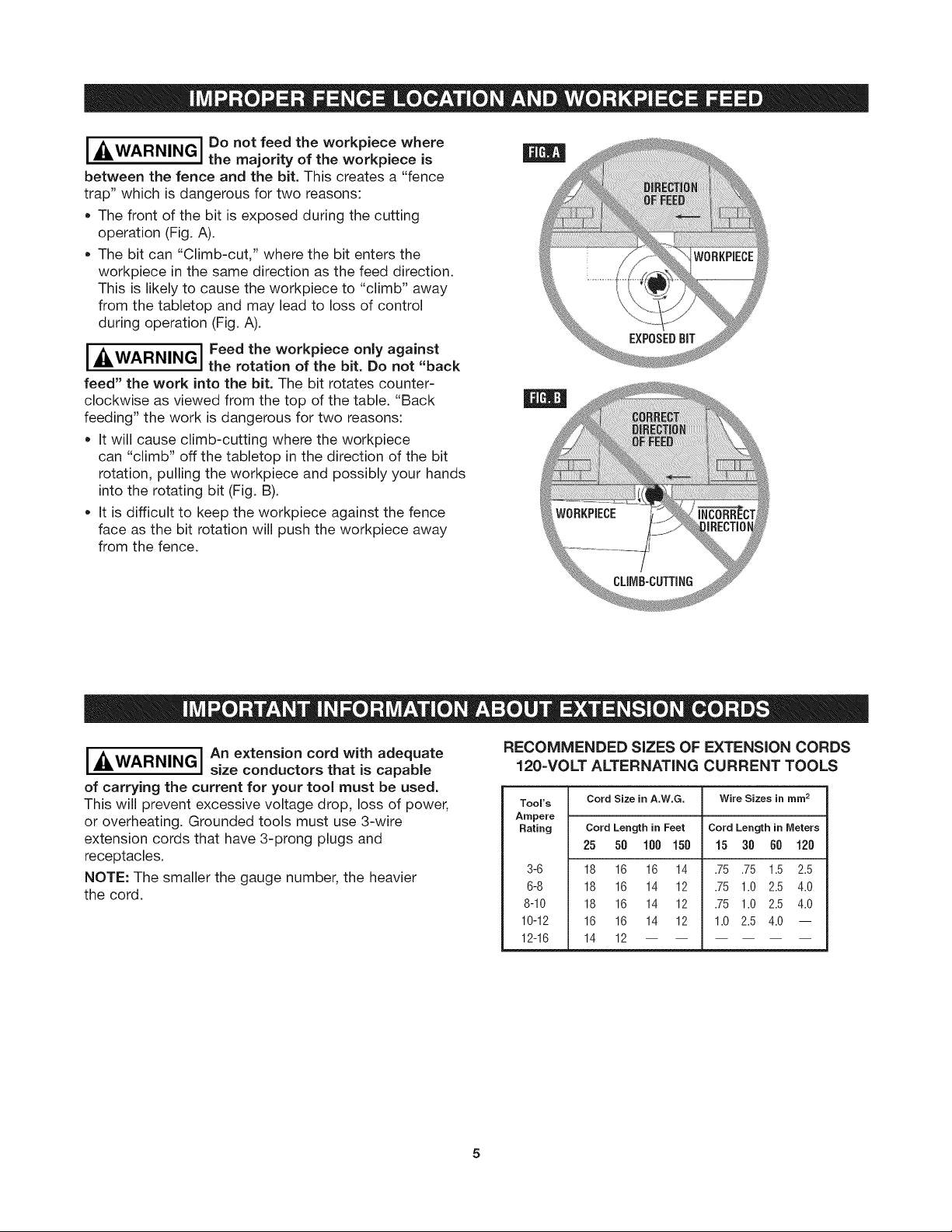
I _4LWARNINGI Do not feed the workpiece where
the majority of the workpiece is
between the fence and the bit. This creates a "fence
trap" which is dangerous for two reasons:
• The front of the bit is exposed during the cutting
operation (Fig. A).
• The bit can "Climb-cut," where the bit enters the
workpiece in the same direction as the feed direction.
This is likely to cause the workpiece to "climb" away
from the tabletop and may lead to loss of control
during operation (Fig. A).
I_IWARNINGI Feed the workpiece only against
the rotation of the bit. Do not "back
feed" the work into the bit. The bit rotates counter-
clockwise as viewed from the top of the table. "Back
feeding" the work is dangerous for two reasons:
• It will cause climb-cutting where the workpiece
can "climb" off the tabletop in the direction of the bit
rotation, pulling the workpiece and possibly your hands
into the rotating bit (Fig. B).
• It is difficult to keep the workpiece against the fence
face as the bit rotation will push the workpiece away
from the fence.
I_ WARNING I An extension cord with adequate
size conductors that is capable
of carrying the current for your tool must be used.
This will prevent excessive voltage drop, loss of power,
or overheating. Grounded tools must use 3-wire
extension cords that have 3-prong plugs and
receptacles.
NOTE: The smaller the gauge number, the heavier
the cord.
RECOMMENDED SIZES OF EXTENSION CORDS
120-VOLT ALTERNATING CURRENT TOOLS
Tool's Cord Size in A.W.G. Wire Sizes in mm 2
Ampere
Rating Cord Length in Feet Cord Length in Meters
25 50 100 150 15 30 60 120
3-6
6-8
8-10
10-12
12-16
18 16 16 14
18 16 14 12
18 16 14 12
16 16 14 12
14 12
.75 .75 1.5 2.5
.75 1.0 2.5 4.0
.75 1.0 2.5 4.0
1.0 2.5 4.0 --

iMPORTANT: Some of the following symbols may be used on your tool. Please study them and learn their
meaning. Proper interpretation of these symbols will allow you to operate the tool better and safer.
Symbol Name Designation/Explanation
V Volts Voltage (potential)
A Amperes Current
Hz Hertz Frequency (cycles per second)
W Watt Power
kg Kilog rams Weight
min Minutes Time
s Seconds Time
Q Diameter Size of drill bits, grinding wheels, etc.
no No load speed Rotational speed, at no load
.../min Revolutions or reciprocation Revolutions, strokes, surface speed, orbits
per minute etc. per minute
0 Off position Zero speed, zero torque...
1,2, 3.... Selector settings Speed, torque, or position settings
I, II, Ill, Higher number means greater speed
Infinitely variable selector Speed is increasing from 0 setting
with off
=I_ Arrow Action in the direction of arrow
"_ Alternating current Type or a characteristic of current
---== Direct current Type or a characteristic of current
i
"_ Alternating or direct current Type or a characteristic of current
[] Class II construction Designates double-insulated construction tools
(_ Earthing terminal Grounding terminal
Warning symbol Alerts user to warning messages
Ni-Cad RBRC seal Designates Ni-Cad battery recycling program
This symbol designates that
this tool complies to NOM
Mexican Standards.
This symbol designates
that this tool is listed
by the Canadian
Standards Association.
0Q°s
This symbol designates that this
tool is listed by Underwriters
Laboratories and listed to
Canadian Standards by
Underwriters Laboratories.
This symbol designates that
components of this tool are
recognized by Underwriters
Laboratories and recognized
to Canadian Standards by
Underwriters Laboratories.

To purchase these and other accessories for your CRAFTSMAN router table and router, visit your local Sears
outlet, or go to www.craftsman.cem
9-26479 CRAFTSMAN Professional Large Router
Mounting Plate
• Molded glass-filled polycarbonate plastic
mounting plate mounts most touters to
the 9=61181 Router Table
• Fasteners for mounting the router to the
mounting plate are not included and must be
purchased separately
IMPORTANT NOTE: The drilling and the
countersinking of holes in the mounting plate are
necessary in order to mount the router to the
mounting plate. The screw heads must be slightly
below the top surface of the mounting plate.
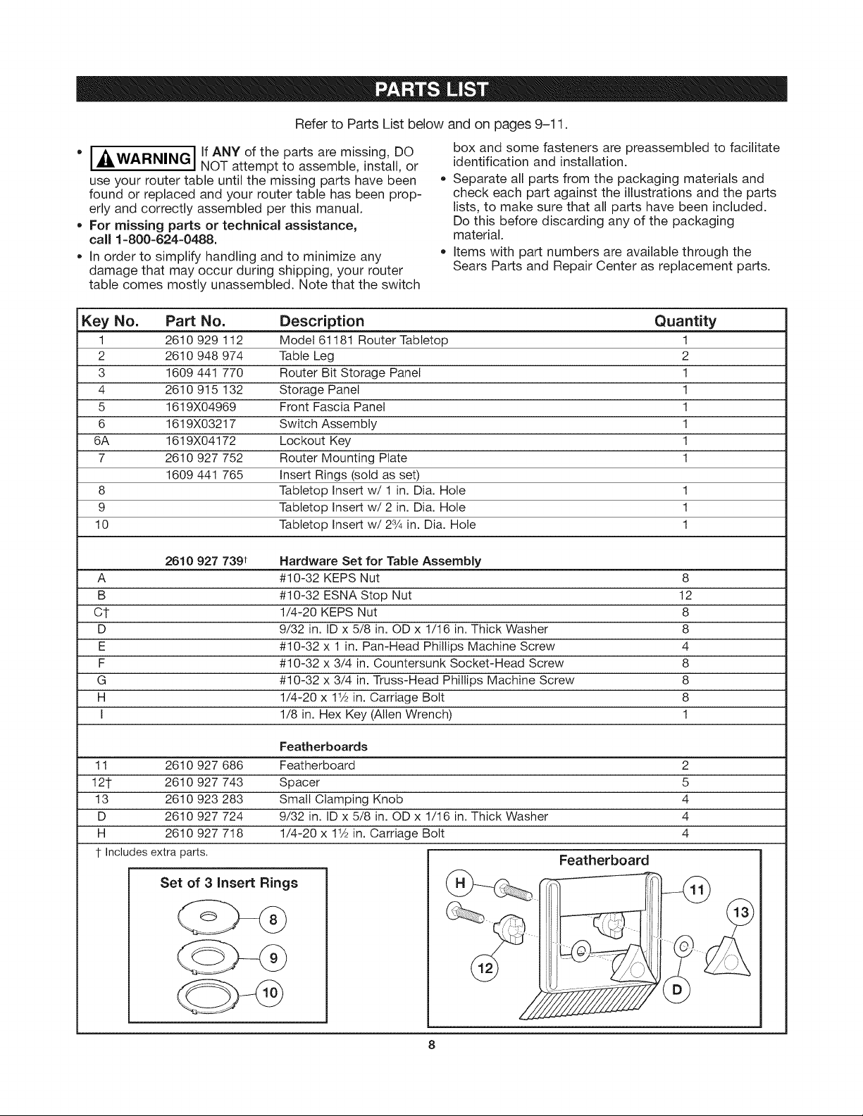
RefertoPartsListbelowandonpages9-11.
* I __ G I If ANY of the parts are missing, DO
,...WARNIN_, NOT attempt to assemble, install, or
!
use your router table until the missing parts have been
found or replaced and your router table has been prop-
erly and correctly assembled per this manual.
* For missing parts or technical assistance,
call 1-800-624-0488.
* In order to simplify handling and to minimize any
damage that may occur during shipping, your router
table comes mostly unassembled. Note that the switch
Key No. Part No. Description Quantity
1 2610 929 112 Model 61181 Router Tabletop 1
2 2610 948 974 Table Leg 2
3 1609 441 770 Router Bit Storage Panel 1
4 2610 915 132 Storage Panel 1
5 1619X04969 Front Fascia Panel 1
6 1619X03217 Switch Assembly 1
6A 1619X04172 Lockout Key 1
7 2610 927 752 Router Mounting Plate 1
1609 441 765 Insert Rings (sold as set)
8 Tabletop Insert w/1 in. Dia. Hole 1
9 Tabletop Insert w/2 in. Dia. Hole 1
10 Tabletop Insert w/23/4 in. Dia. Hole 1
box and some fasteners are preassembled to facilitate
identification and installation.
• Separate all parts from the packaging materials and
check each part against the illustrations and the parts
lists, to make sure that all parts have been included.
Do this before discarding any of the packaging
material.
Items with part numbers are available through the
Sears Parts and Repair Center as replacement parts.
2610 927 739t Hardware Set for Table Assembly
A #10-32 KEPS Nut 8
B #10-32 ESNA Stop Nut 12
C1- 1/4-20 KEPS Nut 8
D 9/32 in. ID x 5/8 in. OD x 1/16 in. Thick Washer 8
E #10-32 x 1 in. Pan-Head Phillips Machine Screw 4
F #10-32 x 3/4 in. Countersunk Socket-Head Screw 8
G #10-32 x 3/4 in. Truss-Head Phillips Machine Screw 8
H 1/4-20 x 11/2in. Carriage Bolt 8
I 1/8 in. Hex Key (Allen Wrench) 1
Featherboards
11 2610 927 686 Featherboard 2
121- 2610 927 743 Spacer 5
13 2610 923 283 Small Clamping Knob 4
D 2610 927 724 9/32 in. ID x 5/8 in. OD x 1/16 in. Thick Washer 4
H 2610 927 718 1/4-20 x 11/2in. Carriage Bolt 4
t Includes extra parts.
Featherboard
Set of 3 insert Rings
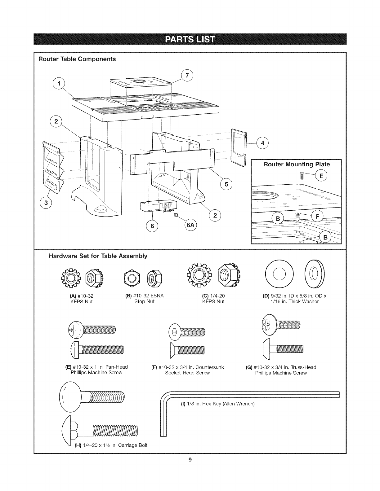
RouterTable Components
Router Mounting Plate
Hardware Set for Table Assembly
e® e® @@
(A) #10-32 (B) #10-32 ESNA (C) 1/4-20
KEPS Nut Stop Nut KEPS Nut
(E) #10-32 x 1 in. Pan-Head
Phillips Machine Screw
(F) #10-32 x 3/4 in. Countersunk
Socket-Head Screw
(I) 1/8 in. Hex Key (Allen Wrench)
(D) 9/32 in. ID x 5/8 in. OD x
1/16 in. Thick Washer
(G) #10-32 x 3/4 in. Truss-Head
Phillips Machine Screw
(H) 1/4-20 x 11A in. Carriage Bolt
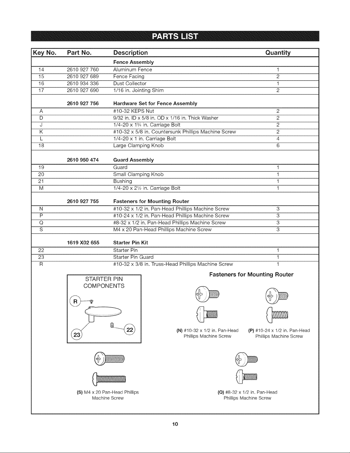
Key No. Part No. Description Quantity
Fence Assembly
14 2610 927 760 Aluminum Fence 1
15 2610 927 689 Fence Facing 2
16 2610 934 336 Dust Collector 1
17 2610 927 690 1/16 in. Jointing Shim 2
2610 927 756 Hardware Set for Fence Assembly
A #10-32 KEPS Nut 2
D 9/32 in. ID x 5/8 in. OD x 1/16 in. Thick Washer 2
J 1/4-20 x 13/4in. Carriage Bolt 2
K #10-32 x 5/8 in. Countersunk Phillips Machine Screw 2
L 1/4-20 x 1 in. Carriage Bolt 4
18 Large Clamping Knob 6
2610 950 474 Guard Assembly
19 Guard 1
20 Small Clamping Knob 1
21 Bushing 1
M 1/4-20 x 21/2in. Carriage Bolt 1
2610 927 755 Fasteners for Mounting Router
N #10-32 x 1/2 in. Pan-Head Phillips Machine Screw 3
P #10-24 x 1/2 in. Pan-Head Phillips Machine Screw 3
Q #8-32 x 1/2 in. Pan-Head Phillips Machine Screw 3
S M4 x 20 Pan-Head Phillips Machine Screw 3
1619 X02 655 Starter Pin Kit
22 Starter Pin 1
23 Starter Pin Guard 1
R #10-32 x 3/8 in. Truss-Head Phillips Machine Screw 1
STARTER PIN
Fasteners for Mounting Router
COMPONENTS
(S) M4 x 20 Pan-Head Phillips
Machine Screw
(N)#10-32 x 1/2 in. Pan-Head
Phillips Machine Screw
(Q) #8-32 x 1/2 in. Pan-Head
Phillips Machine Screw
(P) #10-24 x 1/2 in. Pan-Head
Phillips Machine Screw
10
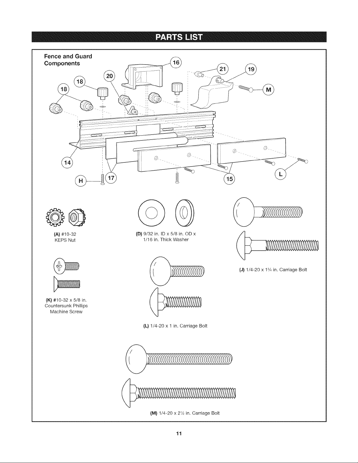
Fence and Guard
Components
@@
(A} #10-32
KEPS Nut
(K) #10-32 x 5/8 in.
Countersunk Phillips
Machine Screw
(D) 9/32 in. ID x 5/8 in. OD x
1/16 in. Thick Washer
(J) 1/4-20 x lS/4 in. Carriage Bolt
(L) 1/4-20 x 1 in. Carriage Bolt
(M) 1/4-20 x 21A in. Carriage Bolt
11
ASSEMBLING THE ROUTER TABLE
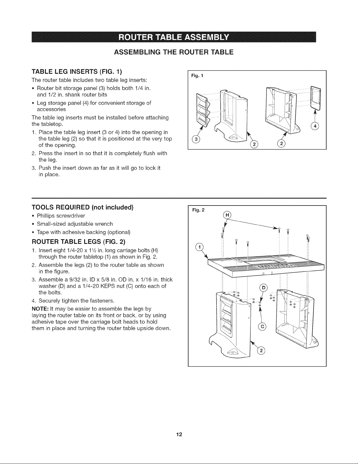
TABLE LEG iNSERTS (FIG. 1)
The router table includes two table leg inserts:
• Router bit storage panel (3) holds both 1/4 in.
and 1/2 in. shank router bits
Leg storage panel (4) for convenient storage of
accessories
The table leg inserts must be installed before attaching
the tabletop.
1. Place the table leg insert (3 or 4) into the opening in
the table leg (2) so that it is positioned at the very top
of the opening.
2. Press the insert in so that it is completely flush with
the leg.
3. Push the insert down as far as it will go to lock it
in place.
TOOLS REQUIRED (not included}
Phillips screwdriver
Small-sized adjustable wrench
Tape with adhesive backing (optional)
ROUTER TABLE LEGS (FIG. 2)
1. Insert eight 1/4-20 x 11½in. long carriage bolts (H)
through the router tabletop (1) as shown in Fig. 2.
2. Assemble the legs (2) to the router table as shown
in the figure.
3. Assemble a 9/32 in. ID x 5/8 in. OD in. x 1/16 in. thick
washer (D) and a 1/4-20 KEPS nut (C) onto each of
the bolts.
4. Securely tighten the fasteners.
NOTE: It may be easier to assemble the legs by
laying the router table on its front or back, or by using
adhesive tape over the carriage bolt heads to hold
them in place and turning the router table upside down.
Fig. 1
Fig. 2
©
12
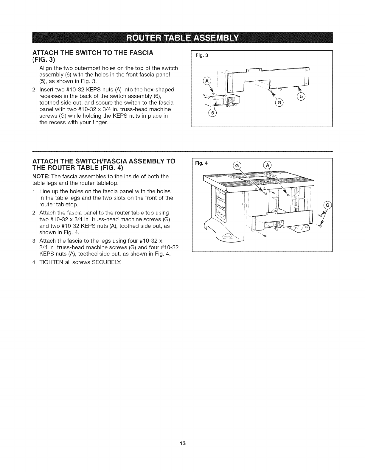
ATTACH THE SWITCH TO THE FASCIA
(FIG. 3)
1. Align the two outermost holes on the top of the switch
assembly (6) with the holes in the front fascia panel
(5), as shown in Fig. 3.
2. Insert two #10-32 KEPS nuts (A) into the hex-shaped
recesses in the back of the switch assembly (6),
toothed side out, and secure the switch to the fascia
panel with two #10-32 x 3/4 in. truss-head machine
screws (G) while holding the KEPS nuts in place in
the recess with your finger.
Fig. 3
ATTACH THE SWITCH/FASCIA ASSEMBLY TO
THE ROUTER TABLE (FIG. 4)
NOTE: The fascia assembles to the inside of both the
table legs and the router tabletop.
1. Line up the holes on the fascia panel with the holes
in the table legs and the two slots on the front of the
router tabletop.
2. Attach the fascia panel to the router table top using
two #10-32 x 3/4 in. truss-head machine screws (G)
and two #10-32 KEPS nuts (A), toothed side out, as
shown in Fig. 4.
3. Attach the fascia to the legs using four #10-32 x
3/4 in. truss-head machine screws (G) and four #10-32
KEPS nuts (A), toothed side out, as shown in Fig. 4.
4. TIGHTEN all screws SECURELY.
Fig. 4
13
ASSEMBLING THE FENCE
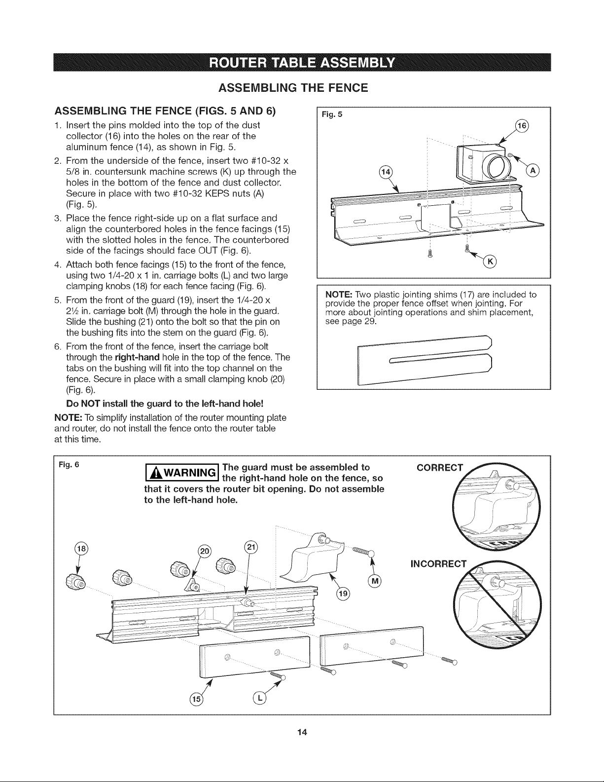
ASSEMBLING THE FENCE (FIGS. 5 AND 6)
1. Insert the pins molded into the top of the dust
collector (16) into the holes on the rear of the
aluminum fence (14), as shown in Fig. 5.
2. From the underside of the fence, insert two #10-32 x
5/8 in. countersunk machine screws (K) up through the
holes in the bottom of the fence and dust collector.
Secure in place with two #10-32 KEPS nuts (A)
(Fig. 5).
3. Place the fence right-side up on a flat surface and
align the counterbored holes in the fence facings (15)
with the slotted holes in the fence. The counterbored
side of the facings should face OUT (Fig. 6).
4. Attach both fence facings (15) to the front of the fence,
using two 1/4-20 x 1 in. carriage bolts (L) and two large
clamping knobs (18) for each fence facing (Fig. 6).
5. From the front of the guard (19), insert the 1/4-20 x
2_ in. carriage bolt (M) through the hole in the guard.
Slide the bushing (21) onto the bolt so that the pin on
the bushing fits into the stem on the guard (Fig. 6).
6. From the front of the fence, insert the carriage bolt
through the right-hand hole in the top of the fence. The
tabs on the bushing will fit into the top channel on the
fence. Secure in place with a small clamping knob (20)
(Fig. 6).
Do NOT install the guard to the left-hand hole!
NOTE: To simplify installation of the router mounting plate
and router, do not install the fence onto the router table
at this time.
Fig. 5
NOTE: Two plastic jointing shims (17) are included to
provide the proper fence offset when jointing. For
more about jointing operations and shim placement,
see page 29.
Fig. 6
I_, I The guard must be assembled to
WARNING, the right-hand hole on the fence, so
that it covers the router bit opening. Do not assemble
to the left-hand hole.
14
CORRECT
s_
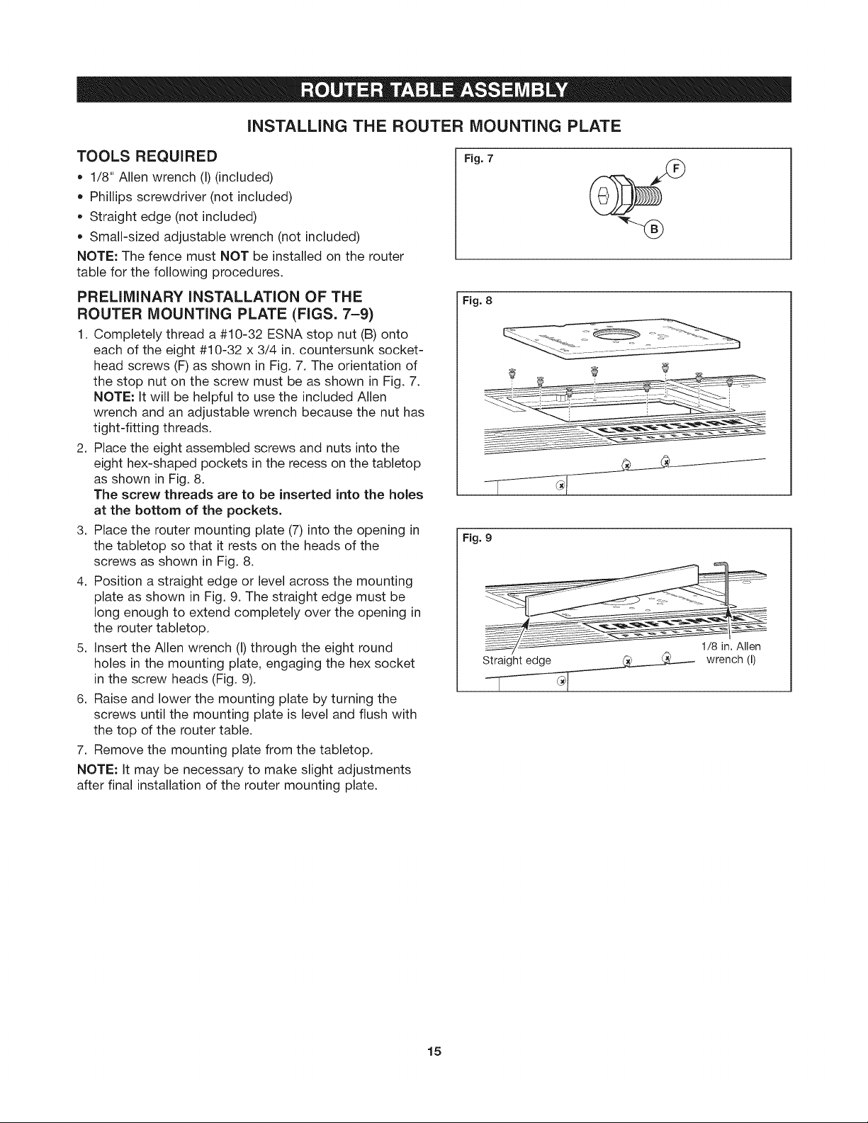
iNSTALLiNG THE ROUTER MOUNTING PLATE
TOOLS REQUIRED
• 1/8" Allen wrench (I) (included)
• Phillips screwdriver (not included)
• Straight edge (not included)
• Small-sized adjustable wrench (not included)
NOTE: The fence must NOT be installed on the router
table for the following procedures.
PRELiMiNARY iNSTALLATiON OF THE
ROUTER MOUNTING PLATE (FIGS. 7-9)
1. Completely thread a #10-32 ESNA stop nut (B) onto
each of the eight #10-32 x 3/4 in. countersunk socket-
head screws (F) as shown in Fig. 7. The orientation of
the stop nut on the screw must be as shown in Fig. 7.
NOTE: It will be helpful to use the included Allen
wrench and an adjustable wrench because the nut has
tight-fitting threads.
2. Place the eight assembled screws and nuts into the
eight hex-shaped pockets in the recess on the tabletop
as shown in Fig. 8.
The screw threads are to be inserted into the holes
at the bottom of the pockets.
3. Place the router mounting plate (7) into the opening in
the tabletop so that it rests on the heads of the
screws as shown in Fig. 8.
4. Position a straight edge or level across the mounting
plate as shown in Fig. 9. The straight edge must be
long enough to extend completely over the opening in
the router tabletop.
5. insert the Allen wrench (I) through the eight round
holes in the mounting plate, engaging the hex socket
in the screw heads (Fig. 9).
6. Raise and lower the mounting plate by turning the
screws until the mounting plate is level and flush with
the top of the router table.
7. Remove the mounting plate from the tabletop.
NOTE: it may be necessary to make slight adjustments
after final installation of the router mounting plate.
Fig. 7
Fig. 8
Fig. 9
Straight edge
1/8 in. Allen
wrench
(I)
15
I-_ I Before using the router table, verify that the router is securely clamped to the router table
WARNING, base. While working, periodically check the router base fasteners clamping tightness.
Router motor vibration can loosen fasteners during use, causing the router to fall from the table.
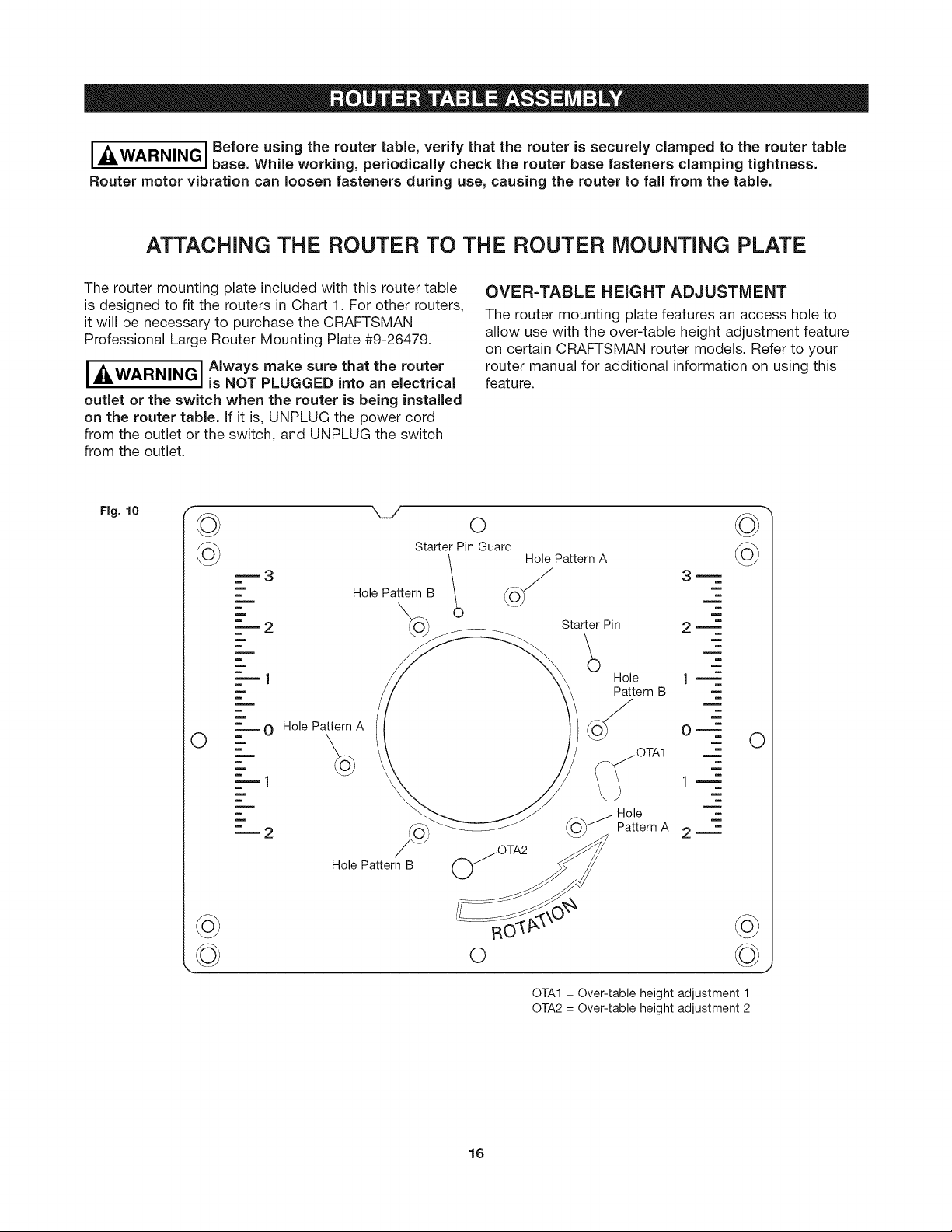
ATTACHING THE ROUTER TO THE ROUTER MOUNTING PLATE
The router mounting plate included with this router table
is designed to fit the routers in Chart 1. For other routers,
it will be necessary to purchase the CRAFTSMAN
Professional Large Router Mounting Plate #9-26479.
i_&WARNINGI Always make sure that the router
outlet or the switch when the router is being installed
on the router table. If it is, UNPLUG the power cord
from the outlet or the switch, and UNPLUG the switch
from the outlet.
Fig. 10
is NOT PLUGGED into an electrical
©
====3
HolePattern B
O
m
m
m
m
m
m
O Hole Pattern A
Starter Pin Guard
OVER=TABLE HEIGHT ADJUSTMENT
The router mounting plate features an access hole to
allow use with the over-table height adjustment feature
on certain CRAFTSMAN router models. Refer to your
router manual for additional information on using this
feature.
o
0 HolePattern A
Starter Pin
Hole
Pattern B
2 m
1 m
O m
©
m
m
m
=
m
m
m
O
©
_=---1
"2
Hole Pattern B
_OTA2
O
16
lm
Hole
Pattern A
OTA1 = Over-table height adjustment 1
OTA2 = Over-table height adjustment 2
2 m
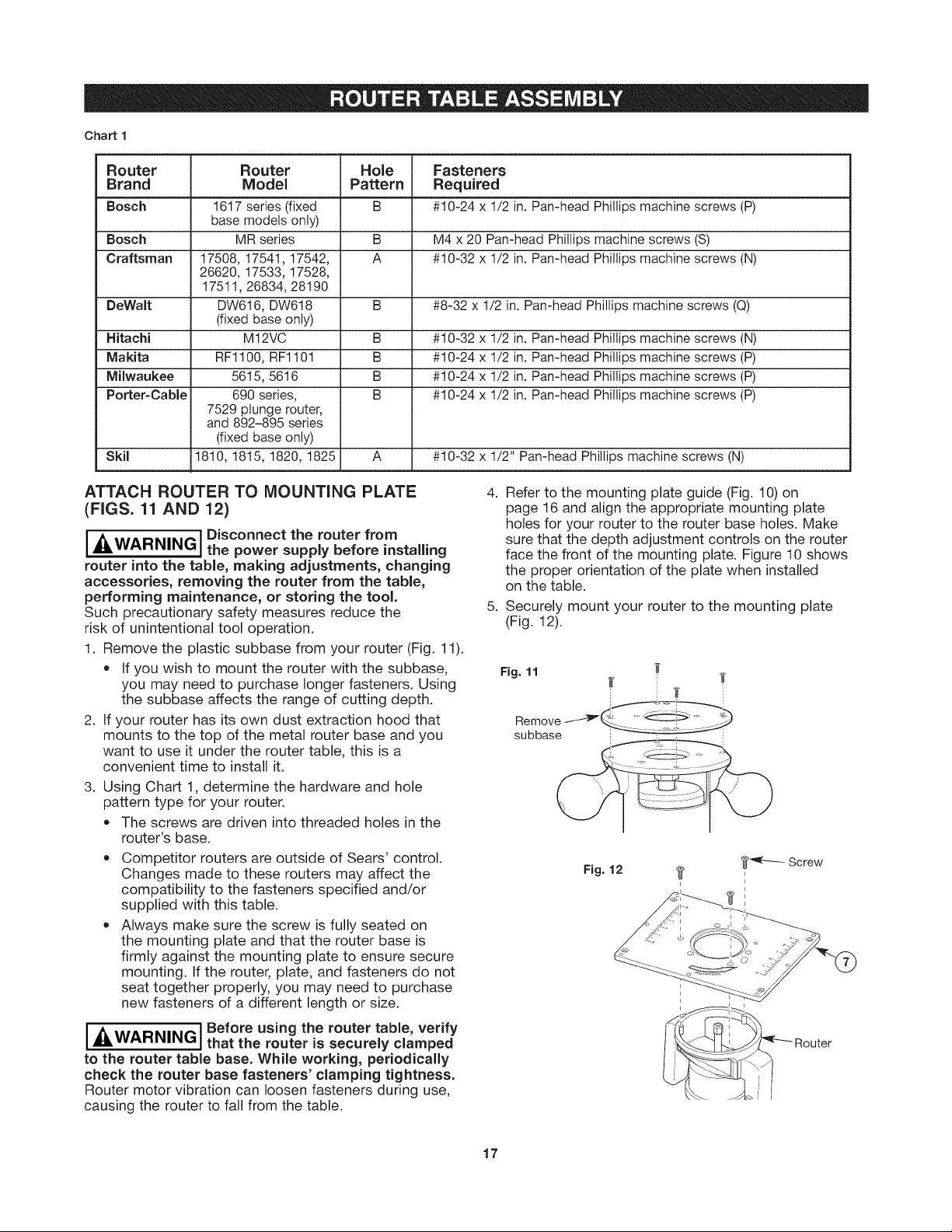
Chart 1
Router Router Hole Fasteners
Brand Model Pattern Required
Bosch 1617 series (fixed B #10-24 x 1/2 in. Pan-head Phillips machine screws (P)
Bosch MR series B M4 x 20 Pan-head Phillips machine screws (S)
Craftsman 17508, 17541, 17542, A #10-32 x 1/2 in. Pan-head Phillips machine screws (N)
DeWalt DW616, DW618 B #8-32 x 1/2 in. Pan-head Phillips machine screws (Q)
Hitachi M12VC B #10-32 x 1/2 in. Pan-head Phillips machine screws (N)
Makita RF1100, RF1101 B #10-24 x 1/2 in. Pan-head Phillips machine screws (P)
Milwaukee 5615, 5616 B #10-24 x 1/2 in. Pan-head Phillips machine screws (P)
Porter-Cable 690 series, B #10-24 x 1/2 in. Pan-head Phillips machine screws (P)
Skil 1810, 1815, 1820, 1825 A #10-32 x 1/2" Pan-head Phillips machine screws (N)
base models only)
26620, 17533, 17528,
17511, 26834, 28190
(fixed base only)
7529 plunge router,
and 892-895 series
(fixed base only)
ATTACH ROUTER TO MOUNTING PLATE
(FIGS. 11 AND 12)
I _i' I Disconnect the router from
WARNING the power supply before installing
router into the table, making adjustments, changing
accessories, removing the router from the table,
performing maintenance, or storing the tool.
Such precautionary safety measures reduce the
risk of unintentional tool operation.
1. Remove the plastic subbase from your router (Fig. 11).
• If you wish to mount the router with the subbase,
you may need to purchase longer fasteners. Using
the subbase affects the range of cutting depth.
2. If your router has its own dust extraction hood that
mounts to the top of the metal router base and you
want to use it under the router table, this is a
convenient time to install it.
3. Using Chart 1, determine the hardware and hole
pattern type for your router.
• The screws are driven into threaded holes in the
router's base.
Competitor routers are outside of Sears' control.
Changes made to these touters may affect the
compatibility to the fasteners specified and/or
supplied with this table.
Always make sure the screw is fully seated on
the mounting plate and that the router base is
firmly against the mounting plate to ensure secure
mounting. If the router, plate, and fasteners do not
seat together properly, you may need to purchase
new fasteners of a different length or size.
4. Refer to the mounting plate guide (Fig. 10) on
page 16 and align the appropriate mounting plate
holes for your router to the router base holes. Make
sure that the depth adjustment controls on the router
face the front of the mounting plate. Figure 10 shows
the proper orientation of the plate when installed
on the table.
5. Securely mount your router to the mounting plate
(Fig. 12).
Fig. 11 _ i o_[
Remove_ J " _i:_ ..... _"
subbase
I-_ I Before using the router table, verify
WARNING, that the router is securely clamped
to the router table base. While working, periodically
check the router base fasteners' clamping tightness.
Router motor vibration can loosen fasteners during use,
causing the router to fall from the table.
17
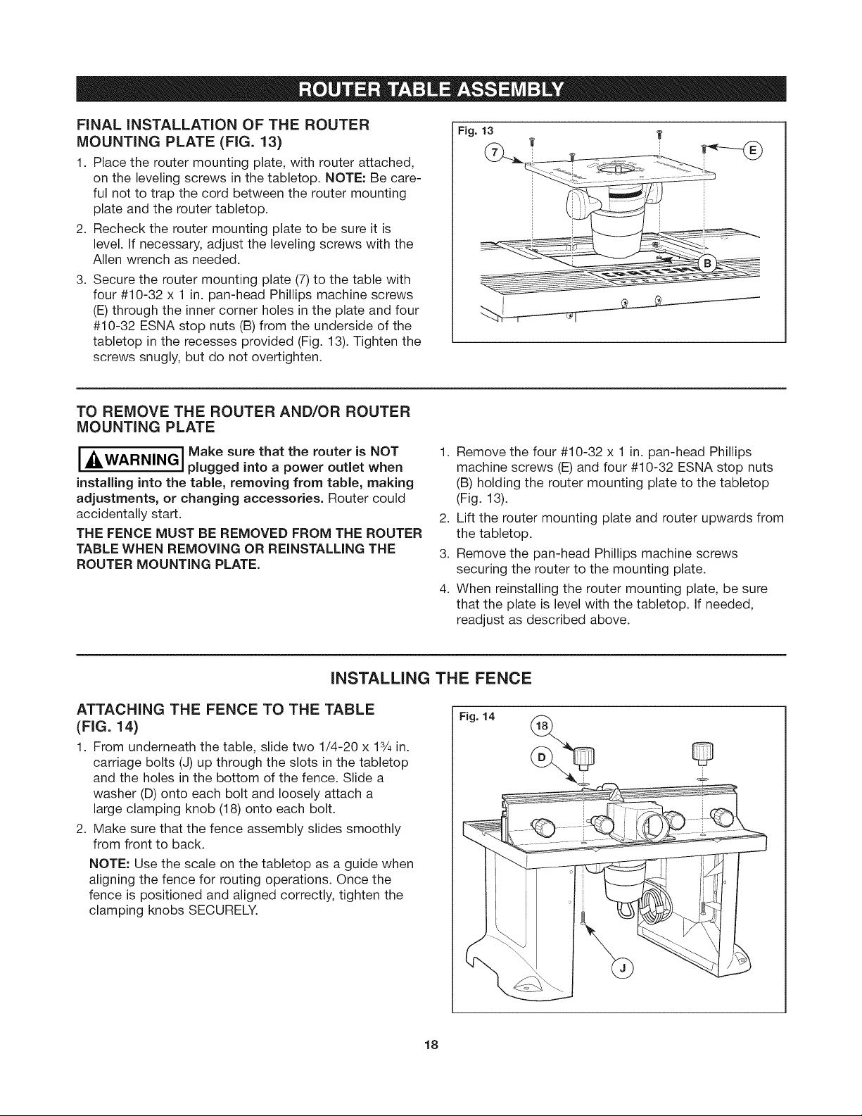
FINAL iNSTALLATiON OF THE ROUTER
MOUNTING PLATE (FIG. 13)
1. Place the router mounting plate, with router attached,
on the leveling screws in the tabletop. NOTE: Be care-
ful not to trap the cord between the router mounting
plate and the router tabletop.
2. Recheck the router mounting plate to be sure it is
level. If necessary, adjust the leveling screws with the
Allen wrench as needed.
3. Secure the router mounting plate (7) to the table with
four #10-32 x 1 in. pan-head Phillips machine screws
(E) through the inner corner holes in the plate and four
#10-32 ESNA stop nuts (B) from the underside of the
tabletop in the recesses provided (Fig. 13). Tighten the
screws snugly, but do not overtighten.
TO REMOVE THE ROUTER AND/OR ROUTER
MOUNTING PLATE
Fig. 13
i__WARNING I Make sure that the router is NOT
installing into the table, removing from table, making
adjustments, or changing accessories. Router could
accidentally start.
THE FENCE MUST BE REMOVED FROM THE ROUTER
TABLE WHEN REMOVING OR REINSTALLING THE
ROUTER MOUNTING PLATE.
plugged into a power outlet when
INSTALLING THE FENCE
ATTACHING THE FENCE TO THE TABLE
(FIG. 14)
1. From underneath the table, slide two 1/4-20 x 13/4in.
carriage bolts (J) up through the slots in the tabletop
and the holes in the bottom of the fence. Slide a
washer (D) onto each bolt and loosely attach a
large clamping knob (18) onto each bolt.
2. Make sure that the fence assembly slides smoothly
from front to back.
NOTE: Use the scale on the tabletop as a guide when
aligning the fence for routing operations. Once the
fence is positioned and aligned correctly, tighten the
clamping knobs SECURELY.
1. Remove the four #10-32 x 1 in. pan-head Phillips
machine screws (E) and four #10-32 ESNA stop nuts
(B) holding the router mounting plate to the tabletop
(Fig. 13).
2. Lift the router mounting plate and router upwards from
the tabletop.
3. Remove the pan-head Phillips machine screws
securing the router to the mounting plate.
4. When reinstalling the router mounting plate, be sure
that the plate is level with the tabletop. If needed,
readjust as described above.
Fig. 14
18
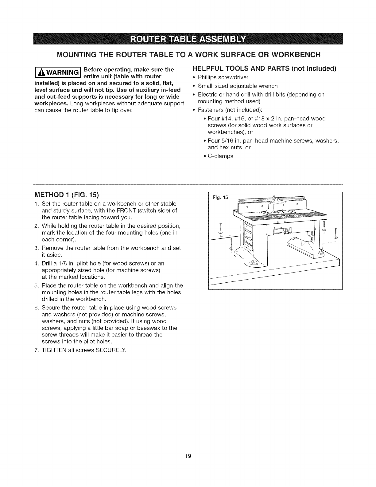
MOUNTING THE ROUTER TABLE TO A WORK SURFACE OR WORKBENCH
I_4=WARNINGI Before operating, make sure the
installed) is placed on and secured to a solid, flat,
level surface and will not tip. Use of auxiliary in-feed
and out-feed supports is necessary for long or wide
workpieces. Long workpieces without adequate support
can cause the router table to tip over.
METHOD 1 (FIG. 15)
1. Set the router table on a workbench or other stable
and sturdy surface, with the FRONT (switch side) of
the router table facing toward you.
2. While holding the router table in the desired position,
mark the location of the four mounting holes (one in
each corner).
3. Remove the router table from the workbench and set
it aside.
4. Drill a 1/8 in. pilot hole (for wood screws) or an
appropriately sized hole (for machine screws)
at the marked locations.
5. Place the router table on the workbench and align the
mounting holes in the router table legs with the holes
drilled in the workbench.
6. Secure the router table in place using wood screws
and washers (not provided) or machine screws,
washers, and nuts (not provided). If using wood
screws, applying a little bar soap or beeswax to the
screw threads will make it easier to thread the
screws into the pilot holes.
7. TIGHTEN all screws SECURELY.
entire unit (table with router
HELPFUL TOOLS AND PARTS (not included)
• Phillips screwdriver
Small-sized adjustable wrench
Electric or hand drill with drill bits (depending on
mounting method used)
Fasteners (not included):
Four #14, #16, or #18 x 2 in. pan-head wood
screws (for solid wood work surfaces or
workbenches), or
Four 5/16 in. pan-head machine screws, washers,
and hex nuts, or
C-clamps
Fig. 15
19
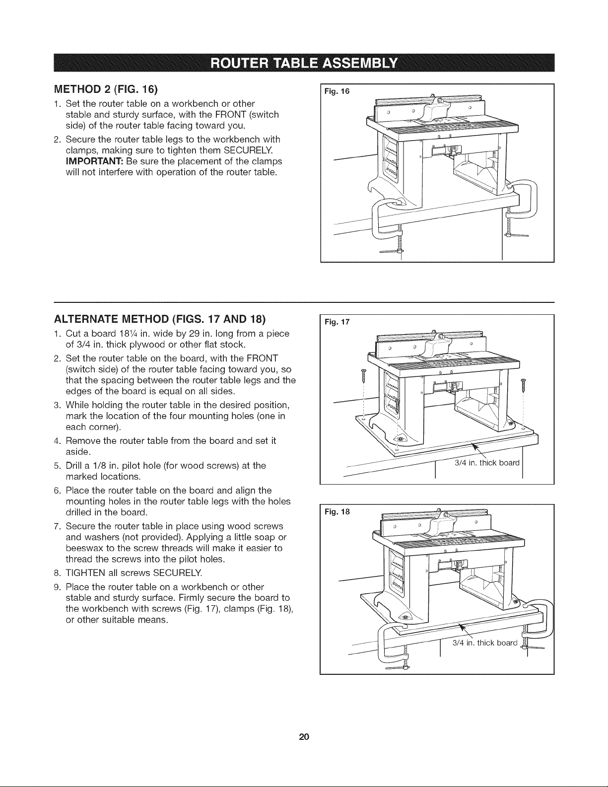
METHOD 2 (FIG. 16)
1. Set the router table on a workbench or other
stable and sturdy surface, with the FRONT (switch
side) of the router table facing toward you.
2. Secure the router table legs to the workbench with
clamps, making sure to tighten them SECURELY.
iMPORTANT: Be sure the placement of the clamps
will not interfere with operation of the router table.
Fig. 16
ALTERNATE METHOD (FIGS. 17 AND 18)
1. Cut a board 184¼in. wide by 29 in. long from a piece
of 3/4 in. thick plywood or other flat stock.
2. Set the router table on the board, with the FRONT
(switch side) of the router table facing toward you, so
that the spacing between the router table legs and the
edges of the board is equal on all sides.
3. While holding the router table in the desired position,
mark the location of the four mounting holes (one in
each corner).
4. Remove the router table from the board and set it
aside.
5. Drill a 1/8 in. pilot hole (for wood screws) at the
marked locations.
6. Place the router table on the board and align the
mounting holes in the router table legs with the holes
drilled in the board.
7. Secure the router table in place using wood screws
and washers (not provided). Applying a little soap or
beeswax to the screw threads will make it easier to
thread the screws into the pilot holes.
8. TIGHTEN all screws SECURELY.
9. Place the router table on a workbench or other
stable and sturdy surface. Firmly secure the board to
the workbench with screws (Fig. 17), clamps (Fig. 18),
or other suitable means.
Fig. 17
4
3/4 in. thick board
Fig. 18
20
3/4 in. thick board
I _ILWARNING I Disconnect the router from the
router into the table, making adjustments, changing
accessories, removing the router from the table,
performing maintenance, or storing the tool. Such
precautionary safety measures reduce the risk of
unintentional tool operation.
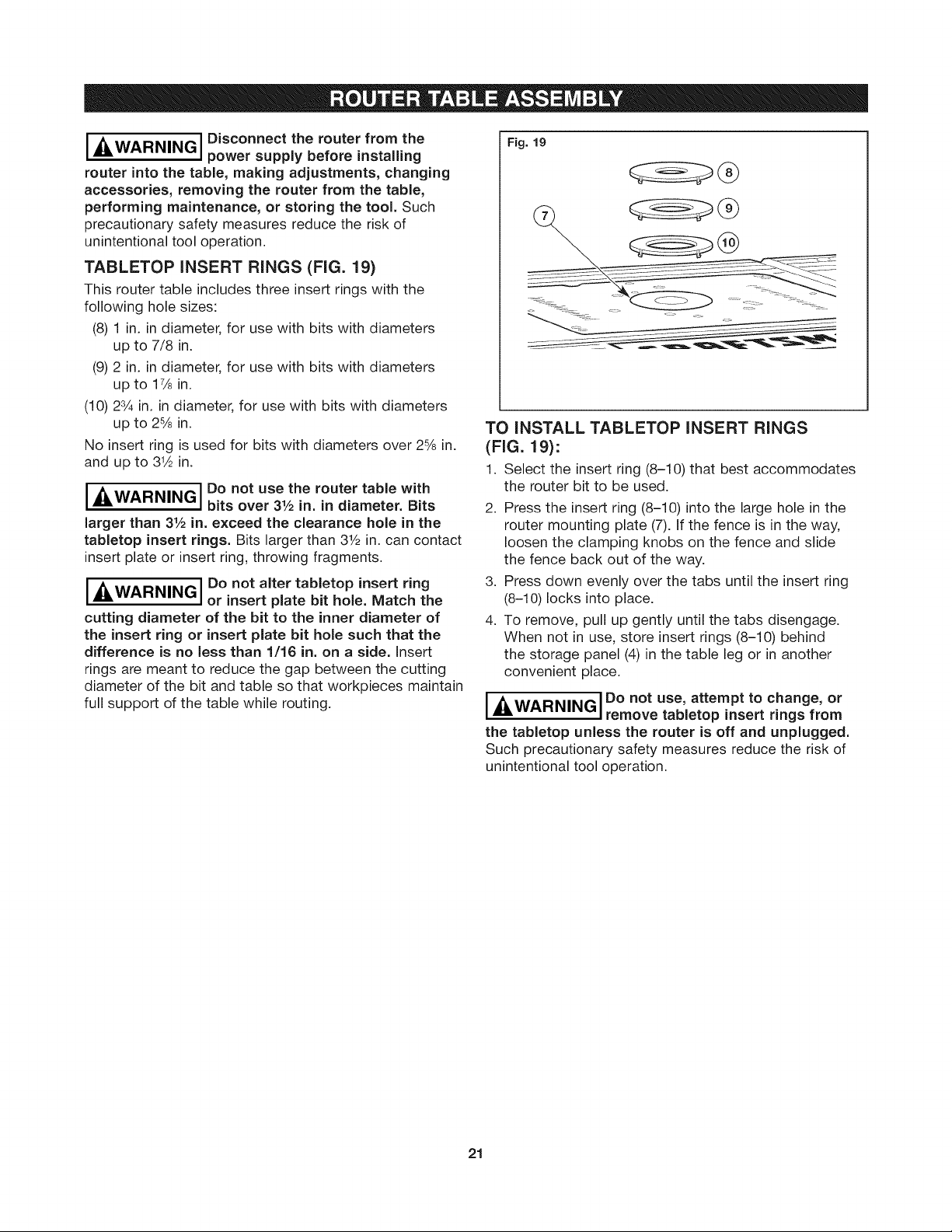
TABLETOP INSERT RINGS (FIG. 19)
This router table includes three insert rings with the
following hole sizes:
(8) 1 in. in diameter, for use with bits with diameters
up to 7/8 in.
(9) 2 in. in diameter, for use with bits with diameters
up to 1% in.
(10) 2% in. in diameter, for use with bits with diameters
up to 2% in.
No insert ring is used for bits with diameters over 2% in.
and up to 3% in.
I A WARNING I Do not use the router table with
I ALL I
larger than 31/2 in. exceed the clearance hole in the
tabletop insert rings. Bits larger than 31/2 in. can contact
insert plate or insert ring, throwing fragments.
I A WARNING I Do not alter tabletop insert ring
IAll I
cutting diameter of the bit to the inner diameter of
the insert ring or insert plate bit hole such that the
difference is no less than 1/16 in. on a side. Insert
rings are meant to reduce the gap between the cutting
diameter of the bit and table so that workpieces maintain
full support of the table while routing.
power supply before installing
bits over 31/2 in. in diameter. Bits
or insert plate bit hole. Match the
Fig. 19
TO INSTALL TABLETOP INSERT RINGS
(FIG. 19):
1. Select the insert ring (8-10) that best accommodates
the router bit to be used.
2. Press the insert ring (8-10) into the large hole in the
router mounting plate (7). If the fence is in the way,
loosen the clamping knobs on the fence and slide
the fence back out of the way.
3. Press down evenly over the tabs until the insert ring
(8-10) locks into place.
4. To remove, pull up gently until the tabs disengage.
When not in use, store insert rings (8-10) behind
the storage panel (4) in the table leg or in another
convenient place.
._WARNING Do not use, attempt to change, or
I I remove tabletop insert rings from
the tabletop unless the router is off and unplugged.
Such precautionary safety measures reduce the risk of
unintentional tool operation.
21
SWITCH CONTROL BOX
[_,WARNINGI Do not plug router motor power
must be plugged into the router table switch. Power
tool switches and controls need to be within your reach
in emergency situations.
GENERAL iNFORMATiON
The power switch is designed for use with most
CRAFTSMAN Router Tables. it provides the convenience
of an ON (RESET)-OFF switch at the front of the table,
thus eliminating the need to reach underneath the table
to turn the router ON and OFF.
The power switch also provides an optional
simultaneous ON-OFF control of an additional
accessory, such as a light, wet/dry vac, etc.
The switch has an internal, resettable circuit
breaker to provide overload protection.
cord into standard wall outlet. It
ELECTRICAL REQUIREMENTS
The switch box cord should only be plugged into a
14-gauge (or heavier), three-wire extension cord with
a three-hole grounding receptacle and three-prong
grounding plug. The extension cord must be plugged
into a matching outlet that has been installed by a
licensed electrician and grounded in accordance with
all local codes and ordinances.
DAMAGED OR WORN EXTENSION CORDS ARE
NOT TO BE USED AND ARE TO BE REPLACED
IMMEDIATELY.
The electrical outlets at the back of the switch box will
accept three-hole extension cords.
The electrical receptacles at the back of the switch box
will accept either three-prong or two-prong plugs from a
router or accessory.
In the event of a malfunction or breakdown, grounding
provides the path of least resistance for electrical current
in order to reduce the risk of electrical shock. This switch
box is equipped with an electrical cord that has an
equipment-grounding connector and a grounding plug.
DO NOT modify the plug from the switch if it does not
plug into the extension cord. Obtain an extension cord
with the proper outlet.
improper connection of the equipment-grounding
conductor can result in risk of an electrical shock.
The conductor with insulation that has a green outer
surface, with or without yellow stripes, is the equipment-
grounding conductor.
DO NOT CONNECT THE EQUIPMENT-GROUNDING
CONDUCTOR TO A LIVE TERMINAL.
Check with a licensed electrician if the grounding
instructions are not completely understood or if there
is doubt as to whether the electrical outlet or extension
cord is properly grounded.
I A WARNINGI Do not permit fingers to touch
iAu=, ]
or removing the plug from the outlet. Risk of Electric
Shock.
IAWARNING I Use the switch box only when
IAUL I
table. Use only with a router that has also been
properly installed on a properly assembled router
table. Such precautionary safety measures reduce
the risk of injury due to loss of control.
I_& WARNING J Do not exceed a total combined
the router and any accessories such as a light or
wet/dry vacuum. The switch has a rating of 15 amps.
CONNECTING THE ROUTER POWER CORD
TO THE SWITCH
[__ J Before connecting router to router
WARNING table switch box, ensure that the
router switch is OFF, and that the router table switch
box is unplugged. Such precautionary safety measures
reduce the risk of unintentional tool operation.
1. Plug the router power cord into one of the electrical
outlets on the back of the switch box.
2. Form the excess power cord into a coil.
3. Wrap two pieces of friction tape or strong cord around
the coiled cord at opposite sides of the coil.
4. Allow some slack so that the cord does not become
stretched when it is plugged into the switch box
outlets.
5. If desired, at this time plug the power cord from an
accessory, such as a wet/dry vac or light, into the
other outlet.
I,_WARNINGJ efore starting to work, ensure
router, accessories, the switch case, and the
extension cord do not and cannot come in contact
with the router or any moving parts of the router.
Such precautionary safety measures reduce the risk
of injury due to loss of control.
terminals of the plug when inserting
properly assembled to the router
rating of 15 amps when connecting
that the power cords from the
22
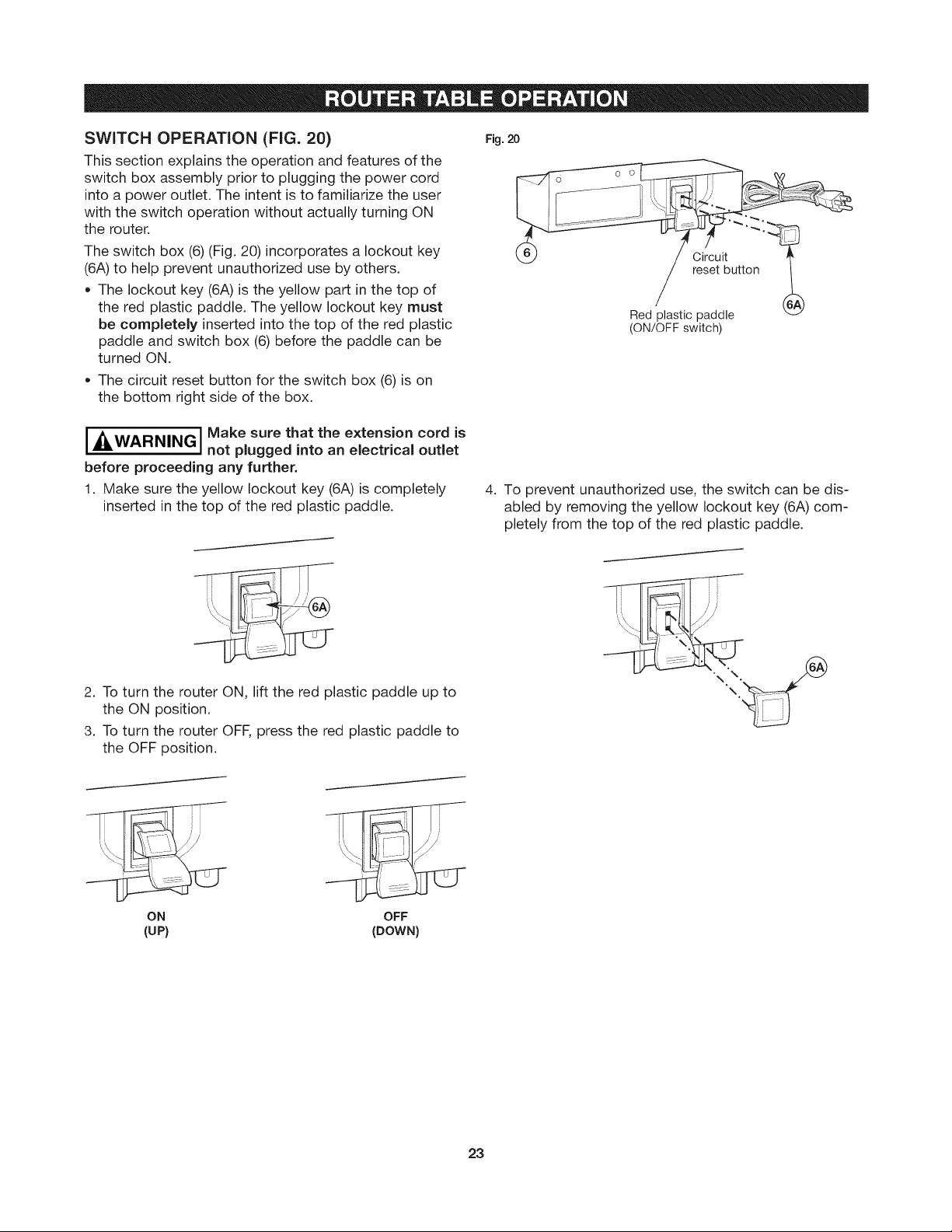
SWITCH OPERATION (FIG. 20)
This section explains the operation and features of the
switch box assembly prior to plugging the power cord
into a power outlet. The intent is to familiarize the user
with the switch operation without actually turning ON
the router.
The switch box (6) (Fig. 20) incorporates a lockout key
(6A) to help prevent unauthorized use by others.
• The lockout key (6A) is the yellow part in the top of
the red plastic paddle. The yellow lockout key must
be completely inserted into the top of the red plastic
paddle and switch box (6) before the paddle can be
turned ON.
The circuit reset button for the switch box (6) is on
the bottom right side of the box.
Fig. 20
Circuit
reset button
Red plastic paddle
(ON/OFFswitch)
i _&WARNINGI Make sure that the extension cord is
before proceeding any further.
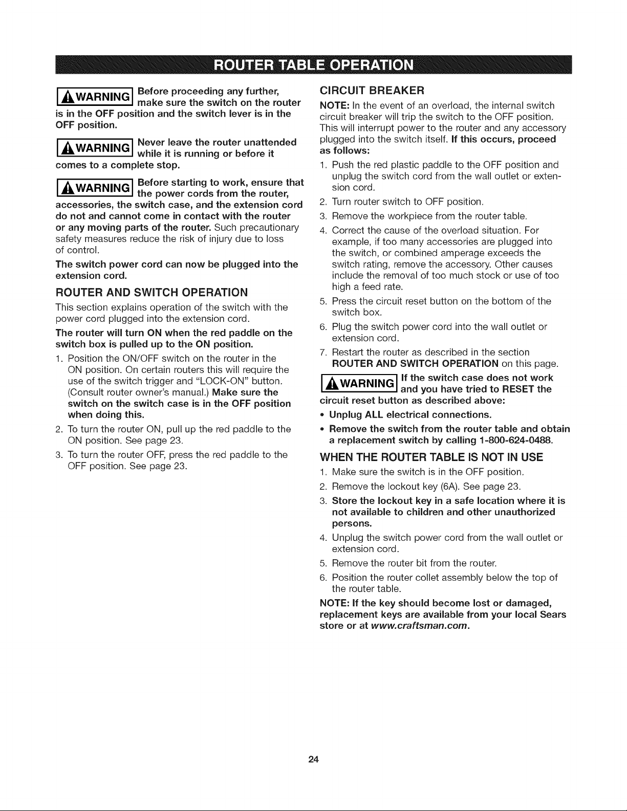
1. Make sure the yellow lockout key (6A) is completely
inserted in the top of the red plastic paddle.
2. To turn the router ON, lift the red plastic paddle up to
the ON position.
3. To turn the router OFF, press the red plastic paddle to
the OFF position.
not plugged into an electrical outlet
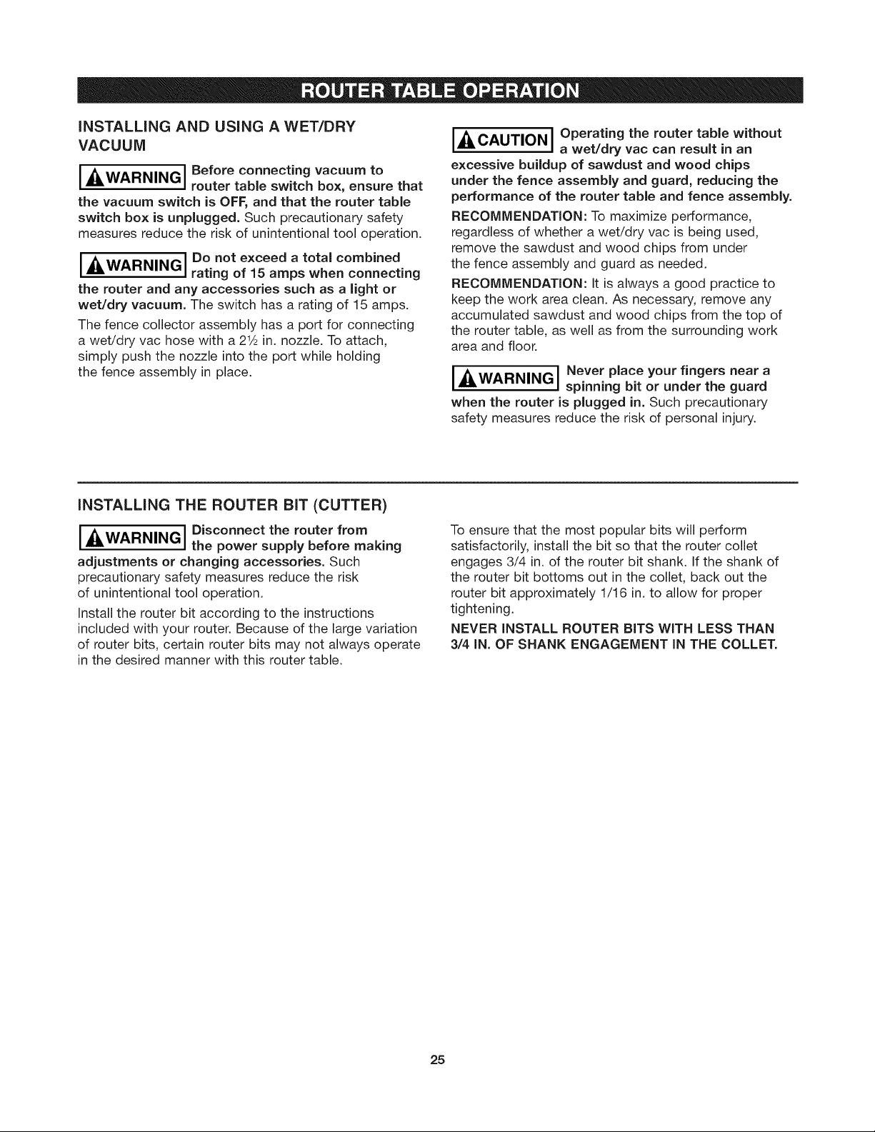
4. To prevent unauthorized use, the switch can be dis-
abled by removing the yellow lockout key (6A) com-
pletely from the top of the red plastic paddle.
ON
(UP)
OFF
(DOWN)
23
[ kWARNING I Before proceeding any further,
is in the OFF position and the switch lever is in the
OFF position.
[. kWARNINGI Never leave the router unattended
comes to a complete stop.
[__WARNING I Before starting to work, ensure that
accessories, the switch case, and the extension cord
do not and cannot come in contact with the router
or any moving parts of the router. Such precautionary
safety measures reduce the risk of injury due to loss
of control.
The switch power cord can now be plugged into the
extension cord.
make sure the switch on the router
while it is running or before it
the power cords from the router,
ROUTER AND SWITCH OPERATION
This section explains operation of the switch with the
power cord plugged into the extension cord.
The router will turn ON when the red paddle on the
switch box is pulled up to the ON position.
1. Position the ON/OFF switch on the router in the
ON position. On certain routers this will require the
use of the switch trigger and "LOCK-ON" button.
(Consult router owner's manual.) Make sure the
switch on the switch case is in the OFF position
when doing this.
2. To turn the router ON, pull up the red paddle to the
ON position. See page 23.
3. To turn the router OFF, press the red paddle to the
OFF position. See page 23.
CIRCUIT BREAKER
NOTE: in the event of an overload, the internal switch
circuit breaker will trip the switch to the OFF position.
This will interrupt power to the router and any accessory
plugged into the switch itself. If this occurs, proceed
as follows:
1. Push the red plastic paddle to the OFF position and
unplug the switch cord from the wall outlet or exten-
sion cord.
2. Turn router switch to OFF position.
3. Remove the workpiece from the router table.
4. Correct the cause of the overload situation. For
example, if too many accessories are plugged into
the switch, or combined amperage exceeds the
switch rating, remove the accessory. Other causes
include the removal of too much stock or use of too
high a feed rate.
5. Press the circuit reset button on the bottom of the
switch box.
6. Plug the switch power cord into the wall outlet or
extension cord.
7. Restart the router as described in the section
ROUTER AND SWITCH OPERATION on this page.
I^WARNING Ill the switch case does not work
In J
circuit reset button as described above:
* Unplug ALL electrical connections.
* Remove the switch from the router table and obtain
a replacement switch by calling 1-800-624-0488.
and you have tried to RESET the
WHEN THE ROUTER TABLE IS NOT IN USE
1. Make sure the switch is in the OFF position.
2. Remove the lockout key (6A). See page 23.
3. Store the lockout key in a safe location where it is
not available to children and other unauthorized
persons.
4. Unplug the switch power cord from the wall outlet or
extension cord.
5. Remove the router bit from the router.
6. Position the router collet assembly below the top of
the router table.
NOTE: If the key should become lost or damaged,
replacement keys are available from your local Sears
store or at www.craftsman.com.
24
iNSTALLiNG AND USING A WET/DRY
VACUUM
I A WARNING I Before connecting vacuum to
[AUL I
the vacuum switch is OFF, and that the router table
switch box is unplugged. Such precautionary safety
measures reduce the risk of unintentional tool operation.
_&WARNINGI Do not exceed a total combined
the router and any accessories such as a light or
wet/dry vacuum. The switch has a rating of 15 amps.
The fence collector assembly has a port for connecting
a wet/dry vac hose with a 2 _&in. nozzle. To attach,
simply push the nozzle into the port while holding
the fence assembly in place.
router table switch box, ensure that
rating of 15 amps when connecting
iNSTALLiNG THE ROUTER BiT (CUTTER)
IAWARNINGI Disconnect the router from
[AUk I
adjustments or changing accessories. Such
precautionary safety measures reduce the risk
of unintentional tool operation.
Install the router bit according to the instructions
included with your router. Because of the large variation
of router bits, certain router bits may not always operate
in the desired manner with this router table.
the power supply before making
[=_ J Operating the router table without
CAUTION a wet/dry vac can result in an
excessive buildup of sawdust and wood chips
under the fence assembly and guard, reducing the
performance of the router table and fence assembly.
RECOMMENDATION: To maximize performance,
regardless of whether a wet/dry vac is being used,
remove the sawdust and wood chips from under
the fence assembly and guard as needed.
RECOMMENDATION: it is always a good practice to
keep the work area clean. As necessary, remove any
accumulated sawdust and wood chips from the top of
the router table, as well as from the surrounding work
area and floor.
I_lk / Never place your fingers near a
WARNING, spinning bit or under the guard
L
when the router is plugged in. Such precautionary
safety measures reduce the risk of personal injury.
To ensure that the most popular bits will perform
satisfactorily, install the bit so that the router collet
engages 3/4 in. of the router bit shank. If the shank of
the router bit bottoms out in the collet, back out the
router bit approximately 1/16 in. to allow for proper
tightening.
NEVER INSTALL ROUTER BITS WITH LESS THAN
3/4 IN. OF SHANK ENGAGEMENT IN THE COLLET.
25
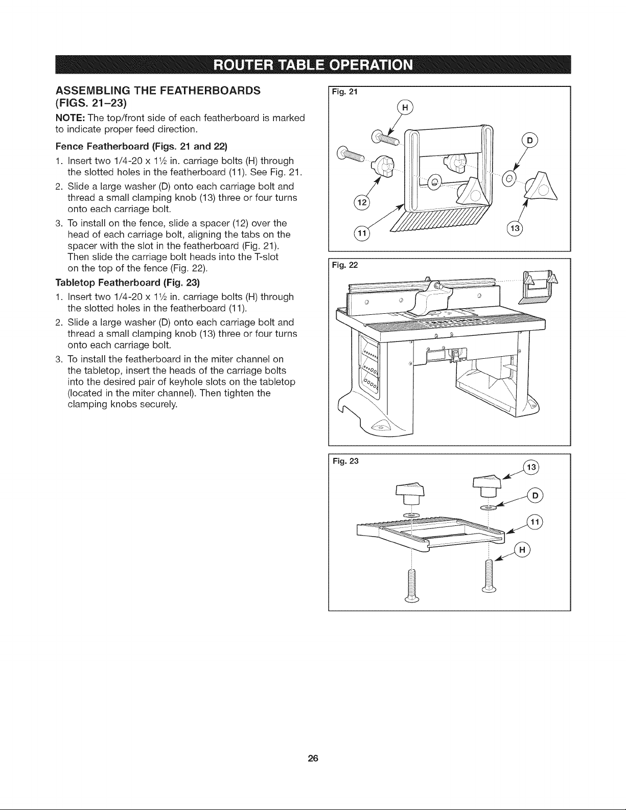
ASSEMBLING THE FEATHERBOARDS
(FIGS. 21-23)
NOTE: The top/front side of each featherboard ismarked
to indicate proper feed direction.
Fence Featherboard (Figs. 21 and 22)
1. Insert two 1/4-20 x 11& in. carriage bolts (H) through
the slotted holes in the featherboard (11). See Fig. 21.
2. Slide a large washer (D) onto each carriage bolt and
thread a small clamping knob (13) three or four turns
onto each carriage bolt.
3. To install on the fence, slide a spacer (12) over the
head of each carriage bolt, aligning the tabs on the
spacer with the slot in the featherboard (Fig. 21).
Then slide the carriage bolt heads into the T-slot
on the top of the fence (Fig. 22).
Tabletop Featherboard (Fig. 23)
1. Insert two 1/4-20 x 11& in. carriage bolts (H) through
the slotted holes in the featherboard (11).
2. Slide a large washer (D) onto each carriage bolt and
thread a small clamping knob (13) three or four turns
onto each carriage bolt.
3. To install the featherboard in the miter channel on
the tabletop, insert the heads of the carriage bolts
into the desired pair of keyhole slots on the tabletop
(located in the miter channel). Then tighten the
clamping knobs securely.
Fig. 21
Fig. 22
%
26
Fig. 23
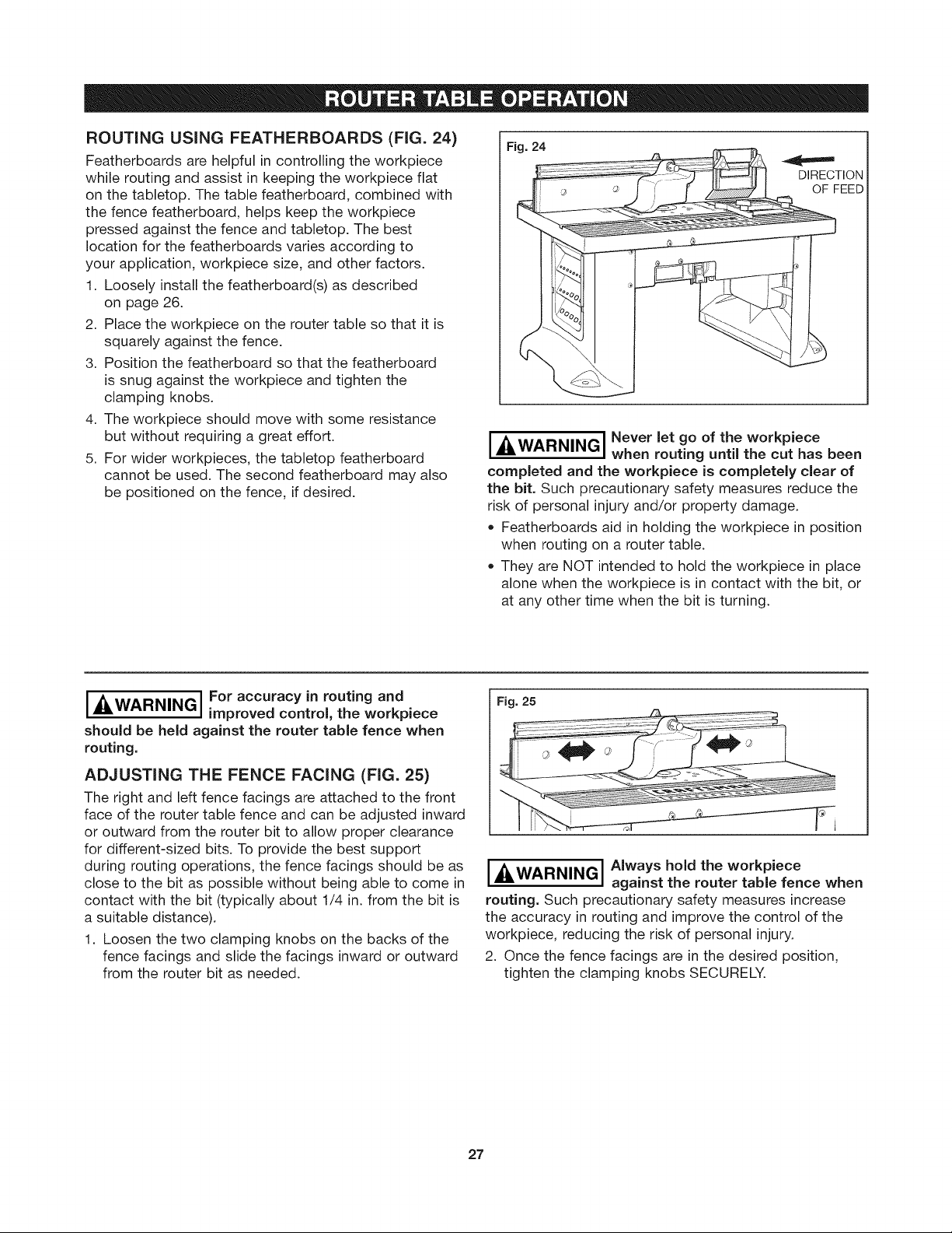
ROUTINGUSING FEATHERBOARDS (FIG. 24)
Featherboards are helpful in controlling the workpiece
while routing and assist in keeping the workpiece flat
on the tabletop. The table featherboard, combined with
the fence featherboard, helps keep the workpiece
pressed against the fence and tabletop. The best
location for the featherboards varies according to
your application, workpiece size, and other factors.
1. Loosely install the featherboard(s) as described
on page 26.
2. Place the workpiece on the router table so that it is
squarely against the fence.
3. Position the featherboard so that the featherboard
is snug against the workpiece and tighten the
clamping knobs.
4. The workpiece should move with some resistance
but without requiring a great effort.
5. For wider workpieces, the tabletop featherboard
cannot be used. The second featherboard may also
be positioned on the fence, if desired.
Fig. 24
DIRECTION
OF FEED
I I Never let go of the workpiece
.ZLWARNING, when routing until the cut has been
completed and the workpiece is completely clear of
the bit. Such precautionary safety measures reduce the
risk of personal injury and/or property damage.
• Featherboards aid in holding the workpiece in position
when routing on a router table.
• They are NOT intended to hold the workpiece in place
alone when the workpiece is in contact with the bit, or
at any other time when the bit is turning.
I .4LWARNINGI For accuracy in routing and
should be held against the router table fence when
routing.
ADJUSTING THE FENCE FACING (FIG. 25)
The right and left fence facings are attached to the front
face of the router table fence and can be adjusted inward
or outward from the router bit to allow proper clearance
for different-sized bits. To provide the best support
during routing operations, the fence facings should be as
close to the bit as possible without being able to come in
contact with the bit (typically about 1/4 in. from the bit is
a suitable distance).
1. Loosen the two clamping knobs on the backs of the
fence facings and slide the facings inward or outward
from the router bit as needed.
improved control, the workpiece
Fig. 25
I =_WARNING I Always hold the workpiece
routing. Such precautionary safety measures increase
the accuracy in routing and improve the control of the
workpiece, reducing the risk of personal injury.
2. Once the fence facings are in the desired position,
tighten the clamping knobs SECURELY.
27
against the router table fence when
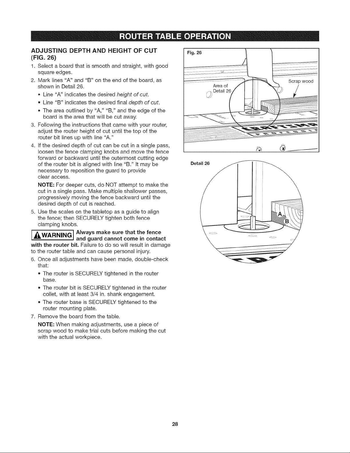
ADJUSTING DEPTH AND HEIGHT OF CUT
(FIG. 26)
1. Select a board that is smooth and straight, with good
square edges.
2. Mark lines "A" and "B" on the end of the board, as
shown in Detail 26.
• Line "A" indicates the desired height of cut.
• Line "B" indicates the desired final depth of cut.
The area outlined by "A," "B," and the edge of the
board is the area that will be cut away.
3. Following the instructions that came with your router,
adjust the router height of cut until the top of the
router bit lines up with line "A."
4. If the desired depth of cut can be cut in a single pass,
loosen the fence clamping knobs and move the fence
forward or backward until the outermost cutting edge
of the router bit is aligned with line "B." It may be
necessary to reposition the guard to provide
clear access.
NOTE: For deeper cuts, do NOT attempt to make the
cut in a single pass. Make multiple shallower passes,
progressively moving the fence backward until the
desired depth of cut is reached.
5. Use the scales on the tabletop as a guide to align
the fence; then SECURELY tighten both fence
clamping knobs.
A WARNING I Always make sure that the fence
with the router bit. Failure to do so will result in damage
to the router table and can cause personal injury.
6. Once all adjustments have been made, double-check
that:
The router is SECURELY tightened in the router
base.
The router bit is SECURELY tightened in the router
collet, with at least 3/4 in. shank engagement.
The router base is SECURELY tightened to the
router mounting plate.
7. Remove the board from the table.
NOTE: When making adjustments, use a piece of
scrap wood to make trial cuts before making the cut
with the actual workpiece.
and guard cannot come in contact
Fig. 26
Detail 26
Area of
/)_ Detail 2_
Lm'
28
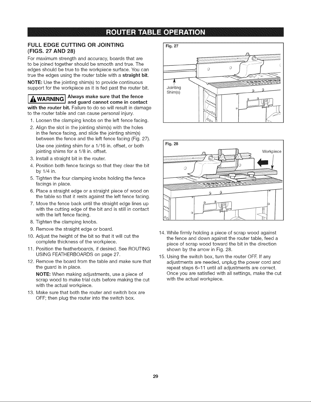
FULL EDGE CUTTING OR JOINTING
(FIGS. 27 AND 28)
For maximum strength and accuracy, boards that are
to be joined together should be smooth and true. The
edges should be true to the workpiece surface. You can
true the edges using the router table with a straight bit.
NOTE: Use the jointing shim(s) to provide continuous
support for the workpiece as it is fed past the router bit.
AWARNING I Always make sure that the fence
B;I I
with the router bit. Failure to do so will result in damage
to the router table and can cause personal injury.
1. Loosen the clamping knobs on the left fence facing.
2. Align the slot in the jointing shim(s) with the holes
in the fence facing, and slide the jointing shim(s)
between the fence and the left fence facing (Fig. 27).
Use one jointing shim for a 1/16 in. offset, or both
jointing shims for a 1/8 in. offset.
3. Install a straight bit in the router.
4. Position both fence facings so that they clear the bit
by 1/4 in.
5. Tighten the four clamping knobs holding the fence
facings in place.
6. Place a straight edge or a straight piece of wood on
the table so that it rests against the left fence facing.
7. Move the fence back until the straight edge lines up
with the cutting edge of the bit and is still in contact
with the left fence facing.
8. Tighten the clamping knobs.
9. Remove the straight edge or board.
10. Adjust the height of the bit so that it will cut the
complete thickness of the workpiece.
11. Position the featherboards, if desired. See ROUTING
USING FEATHERBOARDS on page 27.
12. Remove the board from the table and make sure that
the guard is in place.
NOTE: When making adjustments, use a piece of
scrap wood to make trial cuts before making the cut
with the actual workpiece.
13. Make sure that both the router and switch box are
OFF; then plug the router into the switch box.
and guard cannot come in contact
Fig. 27
Jointing
Shim(s)
Fig. 28
Workpiece
14. While firmly holding a piece of scrap wood against
the fence and down against the router table, feed a
piece of scrap wood toward the bit in the direction
shown by the arrow in Fig. 28.
15. Using the switch box, turn the router OFR If any
adjustments are needed, unplug the power cord and
repeat steps 6-11 until all adjustments are correct.
Once you are satisfied with all settings, make the cut
with the actual workpiece.
29
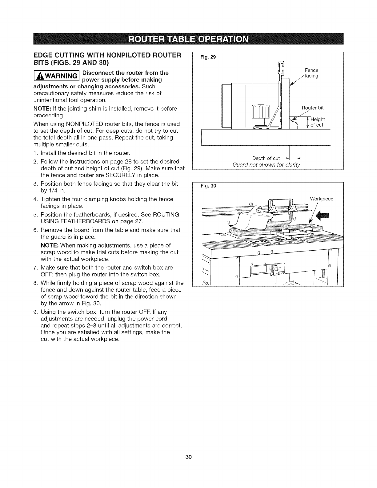
EDGE CUTTING WiTH NONPILOTED ROUTER
BiTS (FIGS. 29 AND 30)
A WARNING I Disconnect the router from the
AlL I
adjustments or changing accessories. Such
precautionary safety measures reduce the risk of
unintentional tool operation.
NOTE: if the jointing shim is installed, remove it before
proceeding.
When using NONPILOTED router bits, the fence is used
to set the depth of cut. For deep cuts, do not try to cut
the total depth all in one pass. Repeat the cut, taking
multiple smaller cuts.
1. Install the desired bit in the router.
2. Follow the instructions on page 28 to set the desired
depth of cut and height of cut (Fig. 29). Make sure that
the fence and router are SECURELY in place.
3. Position both fence facings so that they clear the bit
by 1/4 in.
4. Tighten the four clamping knobs holding the fence
facings in place.
5. Position the featherboards, if desired. See ROUTING
USING FEATHERBOARDS on page 27.
6. Remove the board from the table and make sure that
the guard is in place.
NOTE: When making adjustments, use a piece of
scrap wood to make trial cuts before making the cut
with the actual workpiece.
7. Make sure that both the router and switch box are
OFF; then plug the router into the switch box.
8. While firmly holding a piece of scrap wood against the
fence and down against the router table, feed a piece
of scrap wood toward the bit in the direction shown
by the arrow in Fig. 30.
9. Using the switch box, turn the router OFF. if any
adjustments are needed, unplug the power cord
and repeat steps 2-8 until all adjustments are correct.
Once you are satisfied with all settings, make the
cut with the actual workpiece.
power supply before making
Fig. 29
Fence
Router bit
[
I eightof cut
!
Depth of cut
Guard not shown for clarity
Fig. 30
Workpiece
3O

EDGE CUTTING WITH PILOTED ROUTER BiTS
(FIGS. 31 AND 32)
I,_WARNING I Disconnect the router from the
adjustments or changing accessories. Such
precautionary safety measures reduce the risk
of unintentional tool operation.
NOTE: if the jointing shim is installed, remove it before
proceeding.
1. Install the desired piloted bit in the router.
2. Follow the instructions on page 28 to set the desired
height of cut (Fig. 31). Make sure that the router is
SECURELY in place.
3. Adjust the router table fence back just enough that
the pilot on the router bit will control the depth of cut.
The router bit pilot should just barely protrude past
the fence facings. Tighten the fence clamping knobs
SECURELY.
4. Position both fence facings so that they clear the bit
by 1/4 in.
5. Tighten the four clamping knobs holding the fence
facings in place.
6. Remove the board from the table and make sure that
the guard is in place.
NOTE: When making adjustments, use a piece of
scrap wood to make trial cuts before making the cut
with the actual workpiece.
7. Make sure that both the router and switch box are
OFF; then plug the router into the switch box.
8. While firmly holding a piece of scrap wood against the
fence and down against the router table, feed a piece
of scrap wood toward the bit in the direction shown
by the arrow in Fig. 32.
9. Using the switch box, turn the router OFF. if any
adjustments are needed, unplug the power cord
and repeat steps 2-8 until all adjustments are correct.
Once you are satisfied with all settings, make the cut
with the actual workpiece.
power supply before making
Fig. 31
[
Fig. 32
[
Depth of cut_,
Guard not shown for clarity
Workpiece
Clearance
between fence
and bit
Router bit
pilot
Piloted
I eight
of cut
W
31

GROOVING, FLUTING, AND VEINING
(FIGS. 33 AND 34)
Fig. 33
Location of cut
j __WARNING I Disconnect the router from the
power supply before making
adjustments or changing accessories. Such
precautionary safety measures reduce the risk
of unintentional tool operation.
NOTE: if the jointing shim is installed, remove it before
proceeding.
When performing these routing operations, the use
of featherboards and a push shoe is recommended.
For best results and maximum accuracy, the side of the
workpiece that will be against the fence must be square
and straight.
1. Install the desired end-cutting bit in the router.
2. Follow the instructions on page 28 to set the desired
depth of cut (location of cut) and height of cut
(Fig. 33). Make sure that the fence and router
are SECURELY in place.
iMPORTANT: For deep cuts, do not try to cut the total
depth (controlled by the router bit height) all in one
pass. Repeat the cut, taking smaller cuts until
the desired depth is reached.
3. Position both fence facings so that they provide
continuous support of the workpiece.
4. Tighten the four clamping knobs holding the fence
facings in place.
5. Position the featherboards, if desired. See ROUTING
USING FEATHERBOARDS on page 27.
6. Remove the board from the table and make sure that
the guard is in place.
NOTE: When making adjustments, use a piece of
scrap wood to make trial cuts before making the cut
with the actual workpiece.
7. Make sure that both the router and switch box are
OFF; then plug the router into the switch box.
8. While firmly holding a piece of scrap wood against the
fence and down against the router table, feed a piece
of scrap wood toward the bit in the direction shown
by the arrow in Fig. 34.
9. Using the switch box, turn the router OFR If any
adjustments are needed, unplug the power cord
and repeat steps 2-8 until all adjustments are correct.
Once you are satisfied with all settings, make the cut
with the actual workpiece.
Fence
facing
End cutting
Height
of cut
Guard not shown for clarity
Fig. 34
32

USING A MITER GAUGE
Fig. 35
The miter gauge slot may be used with most
stationary table saw miter gauges that measure
3/4 in. wide x 3/8 in. deep°
NOTE: For ALL routing operations requiring the use of
the miter gauge with the fence, BE SURE to align the
fence using the scales on the top of the router table
before making any cuts. Miters can be cut by loosening
the knob on the protractor head, turning the protractor
head up to 60 ° in either direction and retightening the
protractor head knob.
USING THE STARTER PiN FOR EDGE FORMING OF CURVES
The starter pin (22) is used instead of the fence for
operations that involve routing curves in the workpieceo
It should be used only with bits that have pilot bearings.
Thread the starter pin into the threaded hole in the
mounting plate and tighten securely with a slotted
screwdriver (Fig. 36).
Attach the starter pin guard (23) to the mounting plate
by threading a #10-32 x 3/8 in. truss-head machine
screw (R) through the hole in the guard post and into
the threaded hole in the mounting plate° Align the guard
with the hole in the mounting plate so it is over the bit
and securely fasten the guard in place.
• Always use the starter pin guard when routing with the
starter pin.
When using the starter pin, the feed direction of the
workpiece is always right to left across the front of the
bit (Fig. 37).
Set the workpiece against the front of the starter pin
and swing it slowly into the bit.
While routing, make sure the workpiece is always in
contact with the bit's pilot bearing.
Fig. 37
Miter gauge (not
Starter
pin
DIRECTION
IAWARNING I Use starter pin guard for this
ILL [
type of operation. Do not attempt
to rout very small workpieces. Keep fingers clear
of spinning bit.
Pilot bearing bit
33

fGARANTJA COMPLETA DE UN A_lO SOBRE ESTA HERRAMIENTA CRAFTSMAN PROFESSIONAL "_
Siesta herramienta Craftsman fallara debido a un defecto en el materiaJ o en la mano de obra dentro deJ
aSo de la fecha de adquisici6n, LLAME AL 1-800-4-MY-HOME ® PARA ORGANIZAR UNA REPARACION
GRATUITA {oun reemplazo si la reparaci6n resulta imposible).
Esta garantia no incluye piezas prescindibJes, tales como I_mparas, baterias, brocas o cuchillas.
Esta garantia le otorga derechos legales especificos y usted puede contar con otros derechos, que
pueden variar de estado a estado.
Sears, Roebuck and Co., Hoffman Estates, IL 60179 j
INFORMACION DE SEGURJDAD
IMPORTANTE ............................. 34-38 Montaje de la mesa de fresado .............. 44-53
Accesorios opcionales ........................ 39 Operaci6n de la mesa de fresado ............ 54-65
Liste de partes ............................ 40-43
I'_ I Lea y entienda el manual de se fresador y estas instrucciones. El incumplimiento de todas lasADVERTENCIA instrucciones indicadas a continuaci6n puede dar lugar a lesiones personales graves.
CONSERVE ESTAS INSTRUCCIONES
Area de trabajo
Mantenga el _rea de trabajo limpia y bien iJuminada. Las
mesas desordenadas y las Areas oscuras invitan a que se
produzcan accidentes.
No utilice herramientas mec_nicas en atm6sferas
explosivas, tales como las existentes en presencia de
liquidos, gases o polvos inflamables. Las herramientas
mec&nicas generan chispas y 6stas pueden dar lugar a la
ignici6n del polvo o los vapores.
Mantenga alas personas que se encuentren presentes,
a los niSos, y a los visitantes alejados al utilizar una
herramienta mec&nica. Las distracciones pueden hacer
que usted pierda el control.
Seguridad eJ6ctrica
Las herramientas con conexi6n a tierra deben enchufarse
en un tomacorriente instaJado y conectado a tierra
adecuadamente de acuerdo con todos Jos c6digos y
ordenanzas. Nunca quite eJterminaJ de conexi6n a tierra
ni modifique el enchufe de ninguna forma. No utiJice
enchufes adaptadores. ConsuJte a un eJectricista
caJificado si tiene dudas sobre si el tomacorriente est_
conectado a tierra adecuadamente. En caso de que las
herramientas tengan algQn funcionamiento defectuoso o
averia de tipo el6ctrico, la conexi6n a tierra proporciona
una ruta de resistencia baja para transportar la electricidad
alejandola del usuario. La conexi6n incorrecta a tierra puede
causar sacudidas el6ctricas, quemar, o electrocutar. Las
herramientas con conexi6n a tierra estan equipadas con
un cord6n de tres conductores y enchufes del tipo de tres
terminales. Antes de enchufar la herramienta, asegOrese de
que la tensidn del tomacorriente suministrada se encuentre
dentro del margen de la tensidn especificada en la placa del
fabricante. No utilice herramientas con capacidad nominal
"AC solamente" ("AC only") con una fuente de energfa DC.
Las herramientas con aisiamiento doble est_n equipadas
con un enchufe polarizado (un terminal es m_s ancho
que el otro). Este enchufe entrar& en un tomacorriente
polarizado solamente de una manera. Si el enchufe no
entra por completo en el tomacorriente, d_le la vuelta. Si
sigue sin entrar, p6ngase en contacto con un electricista
competente para instalar un tomacorriente polarizado. No
haga ningSn tipo de cambio en el enchufe. El aislamiento
doble [] elimina la necesidad del sistema de cord6n de
energize tres hilos conectado a tierra y la fuente de energia
conectada a tierra. Antes de enchufar la herramienta,
aseg_rese de que la tensidn del tomacorriente suministrada se
encuentre dentro del margen de la tensidn especificada en la
placa del fabricante. No utilice herramientas con capacidad
nominal "AC solamente" ("AC only") con una fuente de
energfa DC,
Evite el contacto del cuerpo con las superficies
conectadas a tierra tales como tuberias, radiadores,
estufas de cocina, y refrigeradores. Hay mayor riesgo de
que se produzcan sacudidas el6ctricas si su cuerpo esta
conectado a tierra. Si la utilizaci6n de la herramienta
mec&nica en lugares hQmedos es inevitable, se debe usar
un interruptor de circuito para fallos a tierra para suministrar
la energia a la herramienta. Los guantes de goma para
electricista y el calzado antideslizante aumentarAn mAs
la seguridad personal.
No exponga las herramientas mec&nicas a la Iluvia
ni a situaciones hSmedas. La entrada de agua en una
herramienta mecanica aumentarA el riesgo de que se
produzcan sacudidas el6ctricas.
No abuse del cord6n. Nunca use el cord6n para Ilevar
las herramientas ni para sacar el enchufe de un
tomacorriente. Mantenga eJ cord6n alejado del calor,
el aceite, los bordes afiJados, o las piezas m6viles.
Cambie los cordones daSados inmediatamente. Los
cordones daSados aumentan el riesgo de que se produzcan
sacudidas el6ctricas.
AJutilizar una herramienta mec&nica a la intemperie,
utilice un cord6n de extensi6n para intemperie marcado
"W-A" o "W." Estos cordones tienen capacidad nominal para
uso a la intemperie y reducen el riesgo de que se produzcan
sacudidas el6ctricas. Consulte "lnformaci6n importante para
cordones de extensi6n" en este manual.
34

Seguridad personal
Mant_ngase alerta, fijese en Io que est& haciendo, y
use el sentido comt_n cuando utilice una herramienta
mec&nica. No use la herramienta cuando est_ cansado
o se encuentre bajo la influencia de drogas, alcohol,
o medicamentos. Un momento de distracci6n al utilizar
herramientas mec&nicas puede dar lugar a lesiones
personales graves.
Mantenga los protectores de seguridad en su lugar,
Mantenga los protectores de seguridad en orden, ajustados
y alineados correctamente.
Evite el arranque accidental, AsegQrese de que el
interruptor est_ en la posici6n "OFF" (apagado) antes
de enchufar la herramienta. El Ilevar las herramientas con
el dedo en el interruptor o el enchufar herramientas que
tengan el interruptor en la posici6n "ON" (encendido) invita
a que se produzcan accidentes.
Quite las Ilaves de ajuste o de tuerca antes de encender
la herramienta, Una Ilave de ajuste o de tuerca que se deje
puesta en una pieza giratoria de la herramienta puede
ocasionar lesiones personales.
No intente alcanzar demasiado lejos. Mantenga un apoyo
de los pies y un equilibrio adecuados en todo momento. El
apoyo de los pies y el equilibrio adecuados permiten un mejor
control de la herramienta en situaciones inesperadas.
Utilice gafas de seguridad (protecci6n para la cabeza),
Utilice gafas de seguridad (deben cumplir con el est&ndar
Z87.1 de ANSi) en todo momento. Utilice calzado anti-
deslizante y un casco fuerte, si es apropiado. Utilice tambi6n
una m&scara para la cara o para evitar el polvo si la operaci6n
de corte produce polvo, y protectores para los oMos (tapones
u orejeras) durante periodos prolongados de operaci6n.
Utilizaci6n y cuidado de las herramientas
Utilice abrazaderas u otro modo pr&ctico de fijar y
soportar la pieza de trabajo a una plataforma estable.
La sujeci6n de la pieza de trabajo con la mano o contra
el cuerpo resulta inestable y puede ocasionar p6rdida
de control.
No fuerce la herramienta, Use la herramienta correcta
para la aplicaci6n que desea, La herramienta correcta hat&
el trabajo mejor y con m&s seguridad a la capacidad nominal
para la que est& disefiada.
No utilice la herramienta si el interruptor no la enciende
o apaga, Toda herramienta que no se pueda controlar con el
interruptor es peligrosa y debe set reparada.
Desconecte el enchufe de la fuente de energia antes de
hacer cualquier ajuste, cambiar accesorios, o guardar la
herramienta. Estas medidas de seguridad preventivas reducen
el riesgo de arrancar la herramienta accidentalmente.
Mantenga los protectores de seguridad en su lugar.
Mantenga los protectores de seguridad en orden, ajustados
y alineados correctamente.
Guarde las herramientas que no est_ usando fuera del
alcance de los niSos y otras personas no capacitadas,
Las herramientas son peligrosas en las manos de los
usuarios no capacitados.
Nunca deje las herramientas sin vigilancia, Apague la
corriente. NO se aleje de la herramienta hasta que haya
parado por completo.
Mantenga las herramientas con cuidado, Conserve las
herramientas de torte afiladas y limpias, Las herramientas
mantenidas adecuadamente, con bordes de corte afilados,
tienen menos probabilidades de atascarse y son mAs
faciles de controlar. Toda alteraci6n o modificaci6n constituye
un uso incorrecto y puede tenet como resultado una situaci6n
peligrosa.
Compruebe la desalineaci6n o el atasco de las piezas
m6viles, la ruptura de piezas y cualquier otra situaci6n
que pueda afectar el funcionamiento de las herramientas,
Si la herramienta est& daSada, haga que realicen un
servicio de ajustes y reparaciones a la herramienta antes
de usarla, Muchos accidentes son causados pot herramientas
mantenidas deficientemente. Establezca un programa de
mantenimiento peri6dico para la herramienta.
Utilice _nicamente accesorios que est_n recomendados
pot el fabricante de su modelo, Los accesorios que pueden
ser adecuados para una herramienta pueden volverse
peligrosos cuando se utilizan en otra herramienta.
Servicio
El servicio de ajustes y reparaciones de una herramienta
debe ser realizado _nicamente pot personal de
reparaciones competente. El servicio o mantenimiento
realizado pot personal no competente podr[a ocasionar un
peligro de que se produzcan lesiones. Pot ejemplo: Los
cables internos pueden colocarse real o pellizcarse, los
resortes de retorno de los protectores de seguridad pueden
montarse inadecuadamente.
AI realizar servicio de ajustes y reparaciones de una
herramienta, utilice t_nicamente piezas de repuesto
id_nticas, El uso de piezas no autorizadas o el
incumplimiento de las instrucciones de mantenimiento
puede ocasionar un peligro de que se produzcan sacudidas
el_ctricas o lesiones. Ciertos agentes de limpieza, tales como
gasolina, tetracloruro de carbono, amon[aco, etc., pueden
dafiar las piezas de plAstico.
Levante la mesa de fresado s61o de los hordes. Levantar la
mesa de otra superficie puede provocar lesiones personates.
No utilice la mesa de fresado hasta que se hayan
completado todos los pasos de montaje y de instalaci6n.
Antes de carla uso, verifique que las fijaciones y las
abrazaderas de la fresadora se encuentren ajustadas. Una
mesa o fresadora flojas son inestables y pueden moverse
durante el uso, Io que puede ocasionar daSos a la propiedad
o lesiones personales graves.
Desconecte la fresadora de la fuente de energ[a antes de
instalar la fresadora en la mesa, efectuar ajustes, cambiar
accesorios, quitar la fresadora de la mesa, realizar
mantenimiento o almacenar la herramienta. Dichas
medidas de seguridad reducen el riesgo de un accionamiento
accidental de la herramienta.
No enchufe el cable de energia del motor de la fresadora
en un tomacorriente de pared comQn. Siempre enchufe el
cable de la fresadora dentro de la caja del interruptor de la
mesa de fresado. Los interruptores y controles de las
herramientas electricas deben hattarse a su atcance en
situaciones de emergencia.
No toque con los dedos las terminales del enchufe cuando
instale o quite el enchufe del tomacorriente. Riesgo de
Descarga Electrica.
35

Antes de conectar la fresadora o aspiradora a la caja del
interruptor de la mesa de fresado, verifique que la fresadora o
el interruptor de la aspiradora est6n apagados y que la caja
del interruptor de la mesa de fresado se encuentre
desenchufada. Dichas medidas de seguridad reducen el riesgo
de un accionamiento accidental de la herramienta.
Antes de utilizar la mesa de fresado, verifique que la
fresadora est6 bien sujeta a la base de la mesa de fresado.
Mientras trabaja, verifique peri6dicamente que las
abrazaderas de sujeci6n de la base de la fresadora est6n bien
fijas. Las vibraciones de las operaciones de corte pueden aflojar
las abrazaderas del motor de la fresadora y 6ste podria caerse de
la mesa.
Antes de comenzar a trabajar, verifique que los cables de
energia de los accesorios de la fresadora, la caja del
interruptor y el cable de extensi6n no puedan entrar en
contacto con la fresadora o con cualquier pieza en
movimiento de la fresadora. Dichas medidas de seguridad
reducen el riesgo de lesiones debido a la p6rdida de control.
No utilice la mesa de fresado sin la protecci6n superior a
menos que sea necesario para una operaci6n de corte en
particular. Vuelva a colocar la protecci6n inmediatamente
despu6s de finalizar la operaci6n de corte. Quite todo el
polvillo, astillas y otras particulas extra£1as que pueden
afectar su funci6n. La protecci6n ayudar_ a que las manos no
entren en contacto accidental con la broca giratoria.
No utilice brocas de un di_metro de corte que supere el
orificio de espacio de la placa de inserci6n de la superficie de
la mesa o de los anillos de inserci6n. La broca podrfa entrar en
contacto con las placas de inserci6n o anillos de inserci6n, Io que
podrfa arrojar fragmentos.
Nunca use brocas desafiladas o daSadas. Las brocas daSadas
pueden saltar durante el uso. Las brocas desafiladas requieren
m_s fuerza para empujar la pieza de trabajo, Io que posiblemente
puede provocar la rotura de la broca o el contragolpe del material.
Manipule las brocas afiladas con cuidado. Dichas medidas de
seguridad reducen el riesgo de lesiones.
No modifique los anillos de inserci6n o los orificios de la
broca de la placa de inserci6n. Coincida el di_metro de corte
de la broca con el di_metro interno del anillo de inserci6n o
del orificio de la broca de la placa de inserci6n de modo que
la diferencia no sea menor a 1/16 pulg. sobre un lado. Los
anillos de inserci6n se utilizan para reducir el espacio entre el
di_metro de corte de la broca y la mesa para que las piezas de
trabajo reciban un soporte total de la mesa.
Instale la broca de acuerdo con las instrucciones del manual
de la fresadora. Sujete firmemente la broca de la fresadora en
el portabrocas antes de efectuar cortes. Sujetar la broca antes
de efectuar los cortes reduce el riesgo de que 6sta se afloje
durante el funcionamiento.
Nunca coloque los dedos cerca de una broca giratoria o bajo
la protecci6n cuando la fresadora se encuentra enchufada.
Dichas medidas de seguridad reducen el riesgo de una lesi6n.
Nunca sostenga la pieza de trabajo en el lado de alimentaci6n
de salida de la broca. Presionar la pieza de trabajo contra el lado
de alimentaci6n de salida de la guia puede hacer que el material
se trabe y provoque un contragolpe, Io que acercar_ su mano a la
broca.
Controle la pieza de trabajo con la guia para mantener el
control de la misma. No coloque la pieza de trabajo entre la
broca de la fresadora y la guia mientras realiza el fresado
sobre los bordes. Esta colocaci6n har_ que el material se trabe,
posiblemente provocando un contragolpe.
$61o utilice las fresadoras para trabajar con madera,
productos similares a la madera, pl_stico o laminados. No
utilice la fresadora y la mesa de fresado para cortar metales o
darles forma. AsegQrese de que la pieza de trabajo no
contenga clavos u otros objetos duros. Cortar clavos puede
provocar la p6rdida de control de la herramienta o de la pieza de
trabajo.
Nunca arranque la herramienta cuando la broca se encuentre
dentro del material. El lado de corte de la broca puede trabar el
material, provocando la p6rdida de control de la pieza de trabajo.
Alimente la pieza de trabajo s61o en direcci6n opuesta a la
rotaci6n de la broca. No alimente la pieza de trabajo "desde
atr_s" dentro de la broca. La broca gira en sentido contrario a
las agujas del reloj observada desde la parte superior de la mesa.
La alimentaci6n "desde arras" har_ que la pieza de trabajo "salte"
sobre la broca, jalando la pieza de trabajo y posiblemente sus
manos en direcci6n de la broca giratoria.
No alimente la pieza de trabajo dentro de la broca donde se
encuentra la mayor parte de la pieza de trabajo entre la guia y
la broca. Esto crea una "trampa de guia", una situaci6n peligrosa
debido a que la broca queda expuesta. Esto har_ que la pieza
"salte y se aleje" de la superficie de la mesa, Io que podria
provocar la p6rdida de control durante el funcionamiento.
No corte material que se encuentre torcido, flojo o inestable.
La mesa de fresado se encuentra dise_ada para cortar
material piano y recto. Si el material est_ un poco torcido,
pero ann asi se halla estable, corte el material con el lado
c6ncavo contra la mesa o la guia. Cortar el material con el lado
c6ncavo hacia arriba o alejado de la guia puede provocar que el
material torcido o flojo ruede y genere un contragolpe, en cuyo
caso el usuario perderfa el control.
Utilice soportes au×iliares de alimentaci6n de entrada y salida
para piezas de trabajo largas o anchas. Las piezas de trabajo
largas o grandes sin un soporte adecuado pueden saltar de la
mesa o hacer que la mesa se vuelque.
Utilice empujadores, tablas de biselado montadas en forma
vertical u horizontal (varillas con resorte) y otras portapiezas
para sostener la pieza de trabajo. Los empujadores, tablas de
biselado y portapiezas eliminan la necesidad de sostener la pieza
de trabajo cerca de la broca giratoria.
Cuando est6 fresando, nunca suelte la pieza de trabajo hasta
finalizar el corte y la pieza ya no toque la broca. Dichas
medidas de seguridad reducen el riesgo de lesiones y daSos a la
propiedad. Las tablas de biselado ayudan a sostener la pieza de
trabajo en su lugar cuando utiliza una mesa de fresado. No est_n
diseSadas para sostener la pieza de trabajo en su lugar cuando la
pieza de trabajo est_ en contacto con la broca, o en cualquier otto
momento en que la broca est_ girando.
Siempre sostenga la pieza de trabajo contra la guia de la
mesa de fresado mientras trabaja. Dichas medidas de
precauci6n aumentan la precisi6n del fresado y mejoran el control
de la pieza de trabajo, Io que reduce el riesgo de lesiones.
Nunca deje la fresadora sin atenci6n mientras se encuentra
funcionando o antes de que se detenga pot completo. Dichas
medidas de seguridad reducen el riesgo de lesiones y daSos a la
propiedad.
No utilice la mesa como un banco o superficie de trabajo.
Utilizarla con un objetivo diferente al original puede provocarle
daSos y hacerla insegura durante el fresado.
Nunca se pare sobre la mesa ni la utilice como una escalera o
andamio. La mesa podrfa inclinarse o la herramienta de corte
podrfa contactase accidentalmente.
Cuando realice un mantenimiento de la herramienta, s61o
utilice piezas de repuesto CRAFTSMAN. Siga las
instrucciones de la Secci6n de Mantenimiento de este
manual. El uso de piezas no autorizadas o no seguir las
instrucciones de mantenimiento pueden provocar lesiones
personales.
36

Cierto polvo generado pot el lijado, aserrado, amolado y
taladrado mecAnicos, y pot otras actividades de
construcci6n, contiene agentes quimicos que se sabe que
causan cancer, efectos de nacimiento u otros daSos sobre la
eproducci6n. AIgunos ejemplos de estos agentes quimicos son:
• Plomo de pinturas a base de plomo
• Sflice cristalina de ladrillos, cemento, y otros productos de
mamposteria
• Ars6nico y cromo de madera tratada quimicamente
Su riesgo por causa de estas exposiciones varfa, dependiendo de
con cuAnta frecuencia realice este tipo de trabajo. Para reducir su
exposici6n a estos agentes quimicos: trabaje en un Area bien
ventiiada y trabaje con equipo de seguridad aprobado, come por
ejemplo mascaras antipoivo que est6n diseSadas especialmente
para impedir mediante filtraci6n el paso de partfculas
microsc6picas.
,_ADVERTENCIA cuando la mayor parte de la
I No alimente la pieza de trabajo
misma se encuentre entre la guia y la broca. Esto crea
un "trampa de la guia" que es petigrosa pot dos razones:
• La parte frontal de la broca est_ expuesta durante
la operaci6n de corte (Fig. A).
• La broca puede realizar un "fresado concurrente', donde
la broca ingresa a la pieza de trabajo en la misma direc-
ci6n que la direcci6n de la atimentaci6n. Es probable que
esto ocasione que la pieza de trabajo se "monte" fuera
del inserto y que se pierda et control durante la operaci6n
(Fig. A).
I Alimente la pieza de trabajo s61o_ ADVERTENCIA contra la rotacion de la pieza.
No "retroalimente" el trabajo en la broca. La broca gira
en direcci6n contraria a las agujas del retoj, como se ve
desde la parte superior de la mesa. "Retroatimentar" et
trabajo es peligroso pot dos razones:
• Ocasionar_ un fresado concurrente donde la pieza de
trabajo se podr_ "montar" fuera de la mesa, en la direc-
ci6n de la rotaci6n de la broca, desplazando la pieza de
trabajo, y posibtemente sus manos, en la rotaci6n de la
broca (Fig. B).
• Es diffcil mantener la pieza de trabajo contra la cara
de la guia, ya que la rotaci6n de la broca desptazar_
la pieza de trabajo fuera de la guia.
FIG. A
I_1_ I Si es necesario un cable de
ADVERTENCIAI extensi6n, se debe usar uno con
conductores de tama_o adecuado que sea capaz de
transportar la corriente necesaria para la herramienta.
Esto evitar_ caidas de tensi6n excesivas, perdida de poten-
cia o el recatentamiento. Las herramientas conectadas a
tierra deben usar cables de extensi6n de 3 hilos que tengan
enchufes de 3 terminates y recept_cutos para 3 terminales.
NOTA: Cuanto m_s pequeSo es et n0mero de calibre, m_s
es et cable.
TAMAI_OS RECOMENDADOS DE CORDONES
DE EXTENSION HERRAMIENTAS DE 120 V
CORRIENTE ALTERNA
Capacidad
Tamaff0delc0rd6nenA.W.G. Tamaffosdelcableenram2
nominalen
amperesdela L0ngitnddelc0rd6nenpies
herramienta 25 50 100 150
3-6 18 16 16 14
6-8 18 16 14 12
8-10 18 16 14 12
10-12 16 16 14 12
12-16 14 12
37
L0ngituddelc0rd6nenmetros
15 30 60 120
0,75 0,75 1,5 2,5
0,75 1,0 2,5 4,0
0,75 1,0 2,5 4,0
1,0 2,5 4,0 --

IMPORTANTE:Esposibtequealgunosdelossfmbolossiguientesseusenensuherramienta.Porfavor,estL_dietosy
aprendasusignificado.Lainterpretaci6nadecuadadeestossfmboloslepermitir_utilizarlaherramientamejorycon
m_sseguridad.
Simbolo Nombre Designaci6n/explicaci6n
V Volts Tensi6n(potenciat)
A Ampere Corriente
Hz Hertz Frecuencia(cictospotsegundo)
W Watt Potencia
kg Kitogramo Peso
min Minuto Tiempo
s Segundo Tiempo
O Di_metro Tama_odelasbrocastaladradoras,muelas,etc.
no Vetocidadsincarga Vetocidadrotacionalsincarga
.../min Revotuciones o attemaci6n Revoluciones, gotpes, velocidad de superficie,
pot minuto 6rbitas, etc., pot minuto
0 Posici6n "off" (apagado) Vetocidad cero, par motor cero...
1, 2, 3 .... Graduaciones det selector Graduaciones de velocidad, par motor, o posici6n
I, II, Ill, Un nOmero mgs alto significa mayor velocidad
0_ Selector infinitamente variable La velocidad aumenta desde la
con apagado graduaci6n de 0
Flecha Acci6n en la direcci6n de la flecha
Corriente altema Tipo o una caracterfstica de corriente
--_ Corriente continua Tipo o una caractedstica de corriente
Corriente atterna o continua Tipo o una caracterfstica de corriente
[] Construcci6n de clase II Designa las herramientas de construcci6n
_) Terminal de toma de tierra Terminal de conexi6n a tierra
//_ Sfmbolo de advertencia Alerta al usuario sobre mensajes de advertencia
Setlo RBRCTM de Ni-Cd Designa et programa de recictaje de baterfas de Ni-Cd
con aislamiento dobte
E-e
Este simbolo indica que esta
herramienta cumple con la
norma mexicana oficial
(NOM).
Este simbolo indica que esta herramienta
esta catalogada por Underwriters
Laboratories y que Underwriters
Laboratories la ha catalogado segQn
las normas canadienses.
Este simbolo indica que esta
herramienta esta catalogada
por la Canadian Standards
Association.
US
Este simbolo indica que
componentes de esta herramienta
esten reconocida por Underwriters
Laboratories y que Underwriters
Laboratories la ha reconocida
segQn las normas canadienses.
38

Para comprar estos y otros accesorios por su mesa de fresado y su fresadora de CRAFTSMAN, visite su tienda
Sears mas cercana o visite www.craftsman.com
9=26479 Placa de montaje para fresadora grande
NOTA IMPORTANTE: La perforaci6n y el avellanado de los
orificios de ia piaca de montaje son necesarios para montar la
fresadora a ia placa de montaje. Las cabezas de los tomitlos
deben estar un poco pot debajo de la superficie superior de
la placa de montajeo
CRAFTSMAN Professional
• La placa de montaje moldeada de policarbonato
pl_stico reforzada con vidrio puede montar la
mayoria de las fresadoras a la mesa de fresado
9=61181
• Las sujeciones para montar la fresadora a ia piaca de
montaje no est_n inctuidas y deben comprarse pot
separado
39

Consulte la lista de partes debajo y en las paginas 41-43.
" _ArI\II=QTI:::hlt"IAI Si falta ALGUNA de las piezas,
LL ''_''='''_'''v'''l NO ntente armar, nsta ar o usar
su mesa de fresado hasta que todas las piezas fattantes
est@ en sus manos o las haya reemplazado y su mesa de
fresado este armada en forma correcta y completa segOn
Io indicado en este manual.
• Para pJezas faltantes o asistencia t_cnica, Ilame
aJ1=800-624=0488.
• A fin de simplificar el trabajo manual y de minimizar
cualquier dafio que pueda ocurrir durante el envio, la
mesa de fresado viene casi totalmente desensambtada.
Observe que el interruptor y atgunos sujetadores fueron
ensamblados previamente para facilitar la identificaci6n
e instalaci6n.
Separe todas las piezas de los materiales de empaque y
compruebe cada pieza compar_ndola con las ihstra-
clones y la tista de piezas, para asi asegurarse de que se
hayan inchido todas las piezas. H_gato antes de
desechar cualquiera de los materiates de embataje.
Las partes con numeros de parte se encuentran
disponibles a traves det Sears Parts and Repair Center
como piezas de repuesto.
Clave N°. N ° de parte Descripci6n Cantidad
1 2610 929 112 Superficie de la mesa de fresado de Modeto 61181 1
2 2610 948 974 Pata de mesa 2
3 1609 441 770 Panel de almacenamiento de las brocas 1
4 2610 915 132 Panel de almacenamiento 1
5 1619X04969 Panel delantero de la fascia 1
6 1619X03217 Ensambtadura det interruptor con Ilave de btoqueo 1
6A 1619X04172 Llave de btoqueo amaritla 1
7 2610 927 752 Placa de montaje de fresado 1
1609 441 765 Aniltos det inserto (disponibtes como juego)
8 Inserto de la superficie de la mesa con agujero de di_m. de 1 pulg. 1
9 Inserto de la superficie de la mesa con agujero de di_m. de 2 pulg. 1
10 Inserto de la superficie de la mesa con agujero de di_m. de 23/4putg. 1
2610 927 739t Sujetadores de la ensambladura de la mesa
A Tuerca KEPS #10-32 8
B Tuerca ESNA #10-32 12
C1- Tuerca KEPS 1/4-20 8
D Arandela 9/32 putg. D.I. x 5/8 putg. D.E. x 1/16 pulg. 8
E Tornillo de m_quina Phillips #10-32 x 1 putg. 4
F Tornillo de cabeza hueca embutida #10-32 x 3/4 putg. 8
G Tomillo de m_quina Phillips de cabeza segmental #10-32 x 3/4 pulg. 8
H Perno de carruaje 1/4-20 x 11/2putg. 8
I Llave hexagonal de 1/8 pulg. (Llave Allen) 1
Tabla de biselado
11 2610 927 686 Tabta de bisetado 2
121- 2610 927 743 Espaciador 5
13 2610 923 283 Perilla de fijaci6n pequefia 4
D 2610 927 724 Arandeta 9/32 putg. D.I. x 5/8 putg. D.E. x 1/16 putg. 4
H 2610 927 718 Perno de carruaje 1/4-20 x 11/2putg. 4
1 Partesadicionales incluidos.
Juego de 3 anillos del inserto
Tabla de biselado
40

Componentesdelamesadefresado
Placa de montaje
de la fresadora
Sujetadores de la ensambladura de la mesa
@@ ©@
(A) Tuerca KEPS (B) Tuerca ESNA
#10-32 #10-32
(E) Tornillo de maquina
Phillips #10-32 x 1 pulg.
(F) Tornillo de cabeza hueca
embutida #10-32 x 3/4 pulg.
@@
(C) Tuerca KEPS
1/4-20
(G) Tornillo de maquina Phillips de cabeza
(I) Llave hexagonal de 1/8 pulg. (Llave Allen)
(D) Arandela 9/32 pulg. D.I. x
5/8 pulg. D.E. x 1/16 pulg.
segmental #10-32 x 3/4 pulg.
(H) Perno de carruaje 1/4-20 x 11Apulg.
41

Clave N° N ° de parte Descripci6n Cantidad
Ensambladura de la guia
14 2610 927 760 Guia de aluminio 1
15 2610 927 689 Refrentado de la guia 2
16 2610 934 336 Recept_cuto de polvo 1
17 2610 927 690 Cuba de uni6n de 1/16 pulg. 2
2610 927 756 Sujetadores de la ensambladura de la guia
A Tuerca KEPS #10-32 2
D Arandela 9/32 putg. D.I. x 5/8 putg. D.E. x 1/16 pulg. 2
J Perno de carruaje 1/4-20 x 13/4putg. 2
K Tornillo de maquina Phillips de cabeza hueca embutida #10-32 x 5/8 pulg. 2
L Perno de carruaje 1/4-20 x 1 putg. 4
18 Perilla de fijaci6n grande 6
2610 950 474 Ensambladura del protector
19 Protector 1
20 Perilla de fijaci6n peque_a 1
21 Buje 1
M Perno de carruaje 1/4-20 x 21/2pulg. 1
2610 927 755 Sujetadores de montaje de la fresadora
N Tomillo de m_quina Phillips #10-32 x 1/2 putg. 3
P Tomillo de m_quina Phillips #10-24 x 1/2 putg. 3
Q Tornilto de m_quina Phillips #8-32 x 1/2 putg. 3
S Tomillo de m_quina Phillips M4 x 20 3
1619 X02 655 Equipo de la pata de arranque
22 Pata de arranque 1
23 Protector de seguridad de la pata de arranque 1
R Tornilto de m_quina Phillips de cabeza segmental 1
#10-32 x 3/8 pulg.
Equipo de la pata
Sujetadores de montaje de la fresdora
de arranque
(S) Tomillo de maquina
Phillips M4 x 20
(N)Tornillode maquina Phillips
#10-32 x 1/2 pulg.
(Q)Tomillo de maquina Phillips
#8-32 x 1/2 pulg.
(P)Tomillo de maquina Phillips
#10-24 x 1/2 pulg.
42

Componentesde laguia
y del protector
©©
(A) Tuerca KEPS
#10-32
(K) #Tornillo de maquina
Phillips de cabeza hueca
embutida #10-32 x 5/8 pulg.
(D) Arandela 9/32 pulg. D.I. x
5/8 pulg. D.E. x 1/16 pulg.
(J) Perno de carruaje 1/4-20 x 13/4pulg.
(L) Perno de carruaje 1/4-20 x 1 pulg.
(M) Perno de carruaje 1/4-20 x 21A pulg.
43

MONTAJE DE LA MESA DE FRESADO
INSERTOS DE LAS PATAS DE LA MESA
(Fig. 1)
La mesa de fresado inctuye dos insertos para las patas de la
mesa:
• Panel de atmacenamiento para las brocas de ia fresadora
(3) para almacenaje de las brocas de la fresadora con las
espigas de 1/4 puig. y 1/2 putg.
Panel de aimacenamiento de la pata (4) para
atmacenamiento de los accesorios
Se deben instalar los insertos de las patas de la mesa antes
de unir la parte superior de la mesa.
1. Coloque el inserto de ia pata de la mesa (3 o 4) en
la abertura de la pata de la mesa (2) de manera que
quede posicionado en la parte superior de la abertura.
2. Presione el inserto hasta que quede compietamente
nivelado con la pata.
3. Empuje el inserto hacia abajo Io m_s que pueda hasta
que quede seguro en su lugar.
HERRAMIENTAS NECESARIAS (no incluidas)
Destomiltador de estretla
Llave pequefia ajustabte
Cinta con respaido adhesivo (opcionai)
PATAS DE LA MESA DE FRESADO (Fig. 2)
1. Inserte ocho pemos de carruaje 1/4-20 x 11/2pulg.
de largo (H) a traves ia parte superior de la mesa de
fresado (I)como Io muestra ta Figura 2.
2. Ensamble las patas (2) a ia mesa de fresado como
Io muestra en la figura.
3. Ensambte una arandeta de 9/32 puig. de D.I. x 5/8 puig.
de D.E. x 1/16 putg. (D) y una tuerca KEPS de 1/4-20 (C)
en cada uno de los pemos.
4. Apriete fuertemente los sujetadores.
NOTA: Puede set m_s f_cil ensambiar tas patas colocando
la mesa de fresado sobre et frente o la parte posterior, o
utilizando cinta adhesiva en las cabezas de los pernos de
carruaje para sostenertas en su lugar y voltear la mesa de
fresado.
FiG. 1
FiG. 2
44

UNA EL INTERRUPTOR A LA FASCIA (Fig. 3)
1. Alinee los dos orificios m_s extremos en la parte
superior de ta ensambtadura del interruptor (6) con los
orificios en el panel detantero de la fascia (5), como se
muestra en la Fig. 3.
2. Inserte dos tuercas KEPS #10-32 (A)en tas muescas
hexagonates en la parte posterior de la ensembladura
det interruptor (6), con el lado dentado hacia afuera, y
asegure el interruptor al panel de la fascia con dos
tomillos de m_quina de cabeza segmental #10-32 x
3/4 putg. (G) mientras sostiene las tuercas KEPS en la
muesca con et dedo.
UNA LA ENSAMBLADURA DEL
INTERRUPTOPJFASCIA A LA MESA
DE FRESADO (Fig. 4)
NOTA: La fascia se arma al interior tanto de las patas
de la mesa como de la parte superior de la mesa de
fresado.
1. Alfnee los orificios de la fascia con los orificios de las
patas de la mesa y con tas dos ranuras det frente de
la parte superior de la mesa de fresado.
2. Una la fascia a la parte superior de ta mesa de fresado
utitizando dos torniltos de m_quina de cabeza segmental
#10-32 x 3/4 pulg. de largo (G) y dos tuercas KEPS #10-
32 (A), con et lado dentado hacia afuera, como Io muestra
la Fig. 4.
3. Una ta fascia a las patas utilizando cuatro tornillos de
m_quina de cabeza segmental #10-32 x 3/4 putg. de
largo (G) y cuatro tuercas KEPS #10-32 (A), con et lado
dentado hacia afuera, como Io muestra la Fig. 4.
4. APRIETE todos los tornillos FIRMEMENTE.
FIG. 3
45

COMO ARIVIAR LA GUiA
C(DMO ARIVlAR LA GUIA (Figs. 5 y 6) FIG.5
1. Inserte los pasadores moldeados en la parte superior det
recept_cuto del polvo (16) dentro de los orificios en la
parte posterior de la guia de aluminio (14) como se
muestra en ta Fig. 5.
2. Desde la parte inferior de la guia, inserte dos tornitlos
de m_quina embutidos #10-32 x 5/8 putg. (K) hacia
arriba a traves de los orificios en la base de la guia y et
recept_cuto de polvo. Asegure en su lugar con dos
tuercas KEPS #10-32 (A) (Fig. 5).
3. Coloque la guia con et lado derecho hacia arriba en
una superficie plana y alinee los orificios embutidos
en los refrentados de la guia (15) con los orificios
ranurados en la gufa. El tado embutido de los
refrentados debe estar hacia AFUERA (Fig. 6).
4. Una ambos refrentados de la guia (15) hacia el frente de
la guia, con dos pernos de carruaje 1/4-20 x 1 putg. (L) y
dos peritlas de fijaci6n grandes (18) para cada refrentado
de la guia (Fig. 6).
5. Desde el frente del protector (19), inserte el perno de
carruaje 1/4-20 x 21/2putg. (M) a traves del orificio en el
protector. Deslice el buje (21) en et perno de manera que
et pasador en et buje catce en et v_stago det protector
(Fig. 6).
6. Desde et frente de la guia, inserte el perno de carruaje l_
a traves det orificio derecho en la guia. Las leng0etas en
et buje catzar_ en el canal superior en la guia. Asegure en
su lugar con una perilla de fijaci6n (20) (Fig. 6).
iNO instale la guia en el orificio izquierdo!
NOTA: Para simptificar la instataci6n de la placa de montaje
de la fresadora y la fresadora, no instale la guia en la mesa
de fresado en este momento.
NOTA: Se incluyen dos cuSas de uni6n (17) para
permitir la compensaci6n correcta de la guia al
hacer uniones. Para mayores detalles sobre las
operaciones de uniones y la colocaci6n de cuSas,
consulte la pAgina 61.
t
FIG. 6
ADVERTENCIA La protecci6n debe colocarse en el
para que cubra la abertura de la broca de la fresadora.
No la instale en el orificio de la izquierda. /............. ,
I co°° c, .
orificio de la derecha sobre la guia,
_ INCORRECTO
--- \b i
46

C(DlVlO INSTALAR LA PLACA DE IVlONTAJE DE LA FRESADORA
HERRAIVllENTAS NECESARIAS
• Llave Allen de 1/8 pulg. (I)(incluida)
Destornitlador de estrella (no inctuido)
Borde recto (no incluido)
Llave ajustabie peque_a (no inciuida)
NOTA" La gufa NO se debe instatar en la mesa
de fresado para los siguientes procedimientos.
INSTALACION PRELIMINAR DE LA PLACA
DE IViONTAJE DE LA FRESADORA
(Figs. 7-9)
1. Enrosque completamente una tuerca de tope ESNA #10-
32 (B) en cada uno de los ocho torniltos de cabeza hueca
embutida #10-32 x 3/4 putg. (F) como se muestra en la
Fig. 7. La orientaci6n de ia tuerca de tope sobre et tomii-
Io debe set como se muestra en la Fig. 7.
NOTA: Serfa de gran utilidad utilizar la Ilave Alien y una
Ilave ajustabie debido a que la tuerca tiene roscas de
ajuste apretado.
2. Coloque los ocho torniitos y tuercas armados en los ocho
boisiltos de forma hexagonal en la hendidura de la parte
superior de la mesa como Io muestra ia Fig. 8.
Las roscas del tornillo se deben insertar en los
orificios de la parte inferior de los bolsillos.
3. Coloque ia piaca de montaje de fresado (7) en la
abertura en la parte superior de la mesa de forma que
descanse sobre las cabezas de los tomillos como se
muestra en ia Fig. 8.
4. Coloque un borde recto o nivel a Io largo de la ptaca
de montaje como Io muestra la Fig. 9. El borde recto
debe set Io suficientemente largo para extenderse pot
compieto sobre la abertura de la parte superior de la
mesa de fresado.
5. Inserte una Itave Allen (I) a traves de los ocho orificios
redondos de la piaca montabte, colocando la ficha
hexagonal en ias cabezas de los tomiilos (Fig. 9).
6. Levante y baje ia piaca de montaje girando los torniltos
hasta que la piaca de montaje este a nivel y a la misma
altura que ia parte superior de la mesa de fresado.
7. Retire ia piaca de montaje de la parte superior de
la mesa.
NOTA" Puede set necesario hacer leves ajustes despues de
la instaiaci6n final de la piaca de montaje de la fresadora.
FIG. 7
FIG. 8
FIG. 9
Llave Allen
Borde recto _ de 1/8 pulg. (I)
47

_lk&RVl=l::lTPlklr.i& Antes de usar la mesa de fresado, verifique que la fresadora est_ sujetada de forma
............. segura en a base de a mesa de fresado. A trabajar, contro e de forma per 6d ca que
los sujetadores de la base est_n agarrados en forma segura. La vibraci6n del motor de la fresadora puede
aflojar los sujetadores durante el uso, haciendo que la fresadora caiga de la mesa.
COMO FIJAR LA FRESADORA A LA PLACA DE MONTAJE
DE LA FRESADORA
La ptaca de montaje para fresadora inctuida con esta mesa
de fresado est_ diseSada para catzar en las fresadoras en
la table 1. Para otras fresadoras ser_ necesario adquirir
la placa de montaje para fresadora grande CRAFTSMAN
Professional #9-26479.
i A ADVERTENCIAI Siempreverifique que la fresadora
IAUL I NO est_ conectada en una toma
el_ctrica o en el interruptor cuando se est_ instalando
en la mesa de fresado. Si est,, DESCONECTE et cable
electrico de la toma etectrica o del interruptor, y
DESCONECTE et interruptor de la toma etectrica.
FIG. 10
Protector de seguridad de
arranque
_. Patrdn de orificios B
_:--'-2
m
m
ml
Patr6nde
orificios A
mO
O
la pata de
AJUSTE DE ALTURA DE SOBREMESA
La ptaca de montaje de la fresadora tiene los orificios
de acceso para permitir el uso con la funci6n de ajuste
de attura de sobremesa en atgunas fresadoras de
CRAFTSMAN. Consulte el manual de la fresadora para
informaci6n adicionat para usar esta funci6n.
o
Patr6nde orificios A
©
©
/
Pata de arranque 2 -
Patrdnde 1
orificios B =
o_=:-
OTA1 -
O
:---1
m2
1 -
Patr6n de m
___'_orificios A 2 -:
OTA2
Patr6n de orificios B
OTA1 = Ajuste de altura sobremesa 1
OTA2 = Ajuste de altura sobremesa 2
48

Tabla I
Marca de Modelo de Patr6n Tornillos
fresadora fresadora de orificios necesarios
Bosch Serie 1617 B Tornillos de maquina Phillips #10-24 x 1/2 pulg. (P)
(bases fijas Onicamente)
Bosch Serie MR B Tornillos de maquina Phillips M4 x 20 (S)
Craftsman 17508, 17541, 17542, A Tornillos de maquina Phillips #10-32 x 1/2 pulg. (N)
26620, 17533, 17528,
17511, 26834, 28190
DeWalt DW616, DW618 B Tornillos de maquina Phillips #8-32 x 1/2 pulg. (Q)
(bases fijas Qnicamente)
Hitachi M12VC B Tornillos de maquina Phillips #10-32 x 1/2 pulg. (N)
Makita RF1100, RF1101 B Tornillos de maquina Phillips #10-24 x 1/2 pulg. (P)
Milwaukee 5615, 5616 B Tornillos de maquina Phillips #10-24 x 1/2 pulg. (P)
Porter=Cable Serie 690, fresadora B Tornillos de maquina Phillips #10-24 x 1/2 pulg. (P)
de superficie 7529, y
serie 892-895
(bases fijas Qnicamente)
Skil 1810, 1815, 1820, 1825 A Tornillos de maquina Phillips #10-32 x 1/2 pulg. (N)
UNA LA FRESADORA A LA PLACA DE
MONTAJE (Figs. 11 y 12)
I.ADVERTENCIAI Desconeotela ,resadoradel
IR I tomacorriente antes de instalar
la fresadora en la mesa, realizar ajustes, cambios de
accesorios, retirar la fresadora de la mesa, realizar el
mantenimiento o guardar la herramienta. Dichas medidas
de precauci6n reducen el riesgo de funcionamiento no
intencionat de las herramientas.
1. Retire la sub-base pl_stica de la fresadora (Fig. 11).
• Si desea montar la fresadora con la sub-base,
necesitar_ comprar fijaciones m_s largas. Cuando
se utiliza la sub-base, se ve afectado et rango de la
profundidad de corte.
2. Si la fresadora tiene su propia campana de extracci6n de
polvo que se instata en la parte superior de la base de
metal de la fresadora y desea usarla debajo de la mesa
de fresado, este es el momento ideal para instalarla.
3. Siguiendo la tabla 1, determine las piezas y et tipo de
montaje para la fresadora.
• Los tornitlos se meten en orificios enroscados en la
base de la fresadora.
• Las fresadoras de la competencia se encuentran fuera
del control de Sears. Los cambios efectuados a estas
fresadoras pueden afectar la compatibilidad con las
fijaciones especificadas y/o provistas con la presente
mesa.
• Verifique siempre que el tornillo se encuentre bien
colocado sobre la placa de montaje y que la base
de ta fresadora este bien firme contra la placa de
montaje para garantizar un montaje seguro. Si la fre-
sadora, placa o fijaciones no encajan bien, tendr_ que
adquirir fijaciones nuevas de una Iongitud o tamaSo
diferentes.
4. Consulte la gala de la placa de montaje (Fig. 10) en la
p_gina 48 y atinee los orificios de la placa de montaje
apropiados para la fresadora con los orificios de la
base de la fresadora. Verifique que los controles de
ajuste de profundidad en la fresadora esten orientados
hacia el frente de la placa de montaje. La Figura 10
muestra la orientaci6n correcta de la placa cuando
est_ instalada en la mesa.
5. Instale firmemente la fresadora en la ptaca de montaje
(Fig. 12).
FIG. 11
Retire la _
sub-base i =
FIG. 12
i i
i i
ml i ,,
_9_--- Tornillo
I
c_ --"
IAADVERTENCIAI Antes de usar la mesa de
IR I
fresado, verifique que la
fresadora est_ sujetada de forma segura en la base
de la mesa de fresado. AI trabajar, controle de forma
peri6dica que los sujetadores de la base est_n
agarrados en forma segura. La vibraci6n del motor de la
fresadora puede aflojar los sujetadores durante et uso,
haciendo que la fresadora caiga de la mesa.
____- Fresdora
49

INSTALACI()N FINAL DE LA PLACA
DE MONTAJE DE LA FRESADORA (Fig. 13)
1. Cotoque ta placa de montaje de la fresadora, con la fre-
sadora unida, sobre los tornillos niveladores en
la superficie de la mesa. NOTA: Tenga cuidado de no
atrapar el cable entre la placa de montaje de la
fresadora y la superficie de la mesa de fresado.
2. Revise nuevamente la ptaca de montaje de la fresadora
para verificar que este nivelada. Si es necesario, afloje las
tuercas de bloqueo y ajuste los tornillos nivetadores con la
Itave Allen seg0n sea necesario.
3. Atornille ta placa de montaje de la fresadora (7) a la mesa
con cuatro tornillos Phillips de cabeza plana n° 10-32 x
1 putgada (E), a traves de los orificios interiores de las
esquinas de la ptaca y cuatro tuercas de tope ESNA
n° 10-32 (B) desde la parte inferior de la mesa en los
espacios provistos (Fig. 13). Ajuste bien los torniltos,
pero no en exceso.
PARA RETIRAR LA FRESADORA Y/O LA
PLACA DE MONTAJE DE LA FRESADORA
FIG. 13
I ltII^ADVERTENCIAISiempreasegeresede quela
la corriente el_ctrica cuando se est_ instalando a la mesa,
retirando de la mesa, haciendo ajustes, o cambiando los
accesorios. La fresadora podrfa arrancar accidentatmente.
LA GUJA DEBE RETIRARSE DE LA MESA DE FRESADO
AL RETIRAR O VOLVER A INSTALAR LA PLACA DE
MONTAJE DE LA FRESADORA.
fresadora NO ESTE CONECTADO a
INSTALACION DE LA GUJA
C0MO SUJETAR LA GUJA A LA MESA
(Fig. 14)
1. Desde la parte inferior, coloque dos pernos de carruaje
de 1/4-20 x 13Apulg. (J)a traves de los orificios de la
superficie de la mesa y los orificios de la parte inferior de
la gufa. Deslice una arandela (D) en cada perno y sujete
ligeramente una perilta de fijaci6n grande (18) en cada
perno.
2. Verifique que la guia se destice libremente de adetante
hacia atr_s.
NOTA: Utilice la regla de la superficie de la mesa como
referencia al atinear la guia para realizar operaciones
de fresado. Una vez que la guia se encuentra ubicada
y atineada correctamente, ajuste las peritlas de sujeci6n
FIRMEMENTE.
1. Retire los cuatro tornillos Phillips de cabeza plana
n° 10-32 x 1 pulgada (E)y las cuatro tuercas de tope
n° 10-32 ESNA (B) sosteniendo la ptaca de montaje
de la fresadora sobre la mesa (Fig. 13).
2. Levante ta placa de montaje de la fresadora y la
fresadora hacia arriba de la superficie de la mesa.
3. Retire los torniltos de m_quina Phillips que aseguran
la fresadora a la ptaca de montaje.
4. Verifique que la ptaca este nivelada con la mesa.
Si es necesario, vuetva a ajustar segOn se describe
en la secci6n arriba.
5O

COMO MONTAR LA MESA DE FRESADO A UNA SUPERFICIE O BANCO DE TRABAJO
A&RVI=RTI=N_I&IAntes de operar, cerci6rese de que
............. Itoda la unidad (mesa con
fresadora instalada) se coloque y se asegure en una
superficie s61ida, plana, a nivel y que no se incline. Para
piezas de trabajo largas o anchas, utilice soportes auxil-
iares de alimentaci6n hacia dentro y hacia fuera. Las
piezas de trabajo targas sin un soporte adecuado pueden
voltear la mesa o causar que esta se incline.
METODO 1 (Fig. 15)
1. Fije la mesa de fresado en una banca de trabajo o en
otra superficie estable y fuerte, con el FRENTE (lado det
interruptor) de la mesa de fresado hacia usted.
2. Mientras sostiene la mesa de fresado en la posici6n
deseada, marque la ubicaci6n de los cuatro orificios
de montaje (uno en cada esquina).
3. Retire la mesa de fresado de la banca de trabajo y
p6ngata a un lado.
4. Perfore un orificio piloto de 1/8 pulg. (para tornillos de
madera) o un orificio de tamaSo apropiado (para
torniltos de m_quinas) en los puntos marcados.
5. Cotoque la mesa de fresado en ta banca de trabajo y ali-
nee los orificios de montaje en las patas de la mesa con
los orificios perforados en la banca de trabajo.
6. Asegure la mesa de fresado en su tugar usando
torniltos de madera y arandelas (no inctuidas) o
tornillos de m_quina, arandelas, y tuercas (no
inctuidas). Si usa tornillos de madera, aplicar un poco
de jab6n o de cera de abejas las ranuras har_ que sea
m_s f_cil atornillartos en los orificios piloto.
7. APRIETE todos los tornitlos FIRMEMENTE.
HERRAMIENTAS Y PIEZAS 0TILES
(no incluidas)
• Destornillador de estrella
Llave pequeSa ajustabte
Taladro electrico o manual con brocas (dependiendo det
metodo de montaje usado)
Sujetadores (no incluidos):
Cuatro torniltos de madera troncoc6nica #14, #16,
6 #18 x 2 putg. (para superficies o bancas s61idas de
trabajo en madera), o
Cuatro tornillos de m_quina de cabeza troncoc6nica
5/16 putg., arandetas, y tuercas hexagonates, o
Presitlas
FIG. 15
51

IVlETODO 2 (Fig. 16)
1. Fije la mesa de fresado en una banca de trabajo u
otra superficie estable y fuerte, con el FRENTE (tado det
interruptor) de la mesa de fresado hacia usted.
2. Asegure las patas de la mesa de fresado a la banca
de trabajo con presillas, asegur_ndose de apretarlas
FIRMEMENTE.
IMPORTANTE: Aseg0rese que colocar las presillas
no interfiera con la operaci6n de la mesa de fresado.
FIG. 16
METODO ALTERNO (Figs. 17 AND 18)
1. Corte una tabla de 181/4putg. de ancho por 29 pulg. de
largo de un pedazo de madera u otro material ptano de
3/4 putg. de espesor.
2. Fije ta mesa de fresado en la tabla, con el FRENTE (lado
del interruptor) de ta mesa de fresado hacia usted, de
manera que el espacio entre las patas de la mesa de fre-
sado y los bordes de la tabta sean iguates en todos los
lados.
3. Mientras sostiene la mesa de fresado en la posici6n
deseada, marque la ubicaci6n de los cuatro orificios
de montaje (uno en cada esquina).
4. Retire la mesa de fresado de la tabla y p6ngala a un lado.
5. Perfore un orificio piloto de 1/8 pulg. (para tomitlos de
madera) en los puntos seSatados.
6. Cotoque la mesa de fresado en la tabta y alinee los
orificios de montaje en las patas de la mesa con los
orificios perforados en la tabta.
7. Fije la mesa de fresado en su lugar usando tornitlos y
arandelas (no incluidos). Aplicar un poco de jab6n a tas
ranuras del tomitlo har_ que sea m_s f_cit atomiltarlos en
los orificios piloto.
8. APRIETE todos los tornillos FIRMEMENTE.
9. Coloque la mesa de fresado en una banca de trabajo
u otra superficie estable y fuerte. Asegure firmemente la
tabla a la banca de trabajo con torniltos (Fig. 17), presillas
(Fig. 18), u otros medios adecuados.
FIG. 17
4
[
-----"'-i'"-
Tabla de 3/4 pulg.
de espesor
FIG. 18
52
Tabla de 3/4 pulg.
de espesor

NULII^ADVERTENCIAIDesconecte la fresadora del
la fresadora en la mesa, realizar ajustes, cambios de
accesorios, retirar la fresadora de la mesa, realizar el
mantenimiento o guardar la herramienta. Dichas medidas
de precauci6n reducen el riesgo de funcionamiento no
intencionat de las herramientas.
tomacorriente antes de instalar
ANILLOS DE INSERCI(DN DE LA SUPERFIClE
DE LA MESA (Fig. 19)
Esta mesa de fresado viene con tres anitlos de inserci6n, en
los tama5os de agujeros siguientes:
(8) Di_metro de 1 putg. para uso con brocas de la
fresadora con di_metros de hasta 7/8 putg.
(9) Di_metro de 2 putg. para uso con brocas de la
fresadora con di_metros de hasta 1% pulg.
(10) Di_metro de 23/4pulg. para uso con brocas de la
fresadora con di_metros de hasta 2% putg.
Para brocas de la fresadora con di_metros m_s 2% pulg.
hasta 31/2pulg., no utilizar un anillo de inserci6n.
I_ ] No utilice la mesa fresadora con
ADVERTENCIA, brocas de m_s de 31/2pulg. de
di_metro. Las brocas de m_s de 31/2pulg. exceden el
orificio de los anillos de inserci6n de la superficie de la
mesa. Las brocas de m_s de 31/2pulg. pueden hacer con-
tacto con la placa de inserci6n o anilto de inserci6n, Io que
arrojar_ frag mentos.
I-_ I No modifique el anillo de inserci6n
ADVERTENCIA, de la superficie de la mesa o el
orifice de la broca de placa. Ajuste el di_metro de corte
de la broca con el di_metro interno del anillo de
inserci6n o el orificio de la broca de placa de modo que
la diferencia no sea menor a 1/16 pulg. sobre un lado. El
objetivo de los aniltos de inserci6n es reducir la brecha entre
el di_metro de corte de la broca y la mesa para que la
piezas de trabajo mantengan un soporte compteto de la
mesa mientras se reatiza et fresado.
FIG. 19
INSTALACION DE LOS ANILLOS DE
INSERCi(DN DE LA SUPERFICIE DE LA MESA
(Fig. 19):
1. Seleccionar el anilto de inserci6n (8-10) que acomoda la
broca de ta fresadora que se va a utilizar.
2. Montar el anilto de inserci6n (8-10) en el orificio grande
en la placa de montaje de la fresadora (7). Si la gufa esta
en et camino, aflojar las perillas de fijaci6n en la gufa y
destice la gufa de vuelta del camino.
3. Ejercer presi6n pot iguat sobre las leng0etas en el anillo
de inserci6n (8-10), a fin de que las leng(Jetas encajen en
posici6n.
4. Para quitar, hate hacia arriba suavemente hasta que las
lengL_etas se liberen. Cuando no esten en uso, guarde
los anilto de inserci6n de la superficie de la mesa (8-10)
detr_s del panel de atmacenamiento (4) en la pata de la
mesa o en otto lugar que convenga.
I-_ I No use, trate de cambiar o quite
ADVERTENCIA, los anillos de inserci6n de la
superficie de la mesa a menos que la fresadora se
encuentre apagada y desenchufada. Dichas medidas de
seguridad reducen et riesgo de un accionamiento accidental
de la herramienta.
53

INSTRUCCIONES PARA EL INTERRUPTOR
A / NO enchufe el cable de corriente
ADVERTENCIAj del motor de la fresadora en un
tomacorriente est_ndar. Siempre enchufe el cable de la
fresadora en el interruptor de la mesa de la fresadora.
Los interruptores de corriente de la herramienta y los con-
troles deber_n estar a su atcance en casos de emergencia.
INFORMACION GENERAL
El interruptor de energfa se encuentra disefiado para
ser utitizado con la mayorfa de las mesas de fresado
CRAFTSMAN. Ofrece la comodidad de un interruptor de
ENCENDIDO (RECONFIGURACION)/APAGADO en la parte
frontal de la mesa, Io que elimina la necesidad de tenet que
colocar las manos debajo de la mesa para encender o
apagar la fresadora.
El interruptor de energia tambien ofrece un control opcionat
y simult_neo de ENCENDIDO/APAGADO para un accesorio
adicionat, como una tuz, una aspiradora seca/hOmeda, etc.
El interruptor cuenta con un interruptor de circuitos intemo
reconfigurable para ofrecer protecci6n contra sobrecargas.
REQUISITOS ELI_CTRICOS
La caja del interruptor s61o debe enchufarse en un cable
de extensi6n de tres hilos de calibre 14 (o mayor) con un
recept_culo de conexi6n a tierra de tres orificios y un
enchufe con conexi6n a tierra de tres espigas. Et cable
de extensi6n debe enchufarse en un tomacorriente similar
instatado por un electricista con licencia y con conexi6n
a tierra de acuerdo con todos los c6digos y ordenanzas
locales.
NO SE DEBEN USAR Y SE DEBEN REEMPLAZAR DE
INMEDIATO LOS CABLES DE EXTENSION GASTADOS.
Los recept_cutos electricos en la parte posterior de ta caja
del interruptor aceptar_ ya sea un cable de extensi6n de
tres orificios.
Los recept_culos electricos en la parte posterior de la caja
det interruptor aceptar_n ya sea enchufes de dos o tres
terminales de una fresadora o accesorio.
En el caso de una fatla, la conexi6n a tierra ofrece la ruta de
menor resistencia para la corriente electrica con el fin de
reducir el riesgo de choque etectrico. Esta caja interruptora
viene equipada con un cable electrico que tiene un conec-
tot y un enchufe para conexi6n a tierra.
NO modifique el enchufe det interruptor si no se conecta en
el cable de extensi6n. Obtenga un cable de extensi6n con
la toma etectrica correcta.
La conexi6n incorrecta del conductor de conexi6n
a tierra del equipo puede resultar en riesgo de choque
el_ctrico. El conductor con aistamiento que tiene una
superficie exterior verde con o sin las rayas amarillas, es
el conductor de conexi6n a tierra det equipo.
NO CONECTE EL CONDUCTOR DE CONEXION A
TIERRA DEL EQUIPO A UNA TERMINAL ACTIVA.
Consutte con un electricista con licencia si tas instrucciones
para conexi6n a tierra no se entienden claramente o si hay
duda respecto a la conexi6n a tierra correcta de la toma o
extensi6n etectrica.
[_li I No permita que sus dedos tengan
ADVERTENClA, contacto con las terminales del
enchufe al instalar o quitar el enchufe del tomacorri-
ente. Riesgo de Descarga Electrica.
[__ll j Use la caja del interruptorADVERTENCIA s61o cuando est_ ensamblada
adecuadamente en la mesa de la fresadora. Use la
misma s61o con una fresadora que haya sido instalada
de forma adecuada en la mesa de fresado ensamblada
correctamente. Tales medidas de precauci6n reducen et
riesgo de lesiones debido a la perdida de control.
[_il I En total, no se deber_n superar
ADVERTENCIA, los15amperes al conectar la
fresadora y cualquier otto accesorio tal como una luz
o aspiradora. El interruptor posee una capacidad de 15
amperes.
COIVlO CONECTAR EL CABLE ELI_CTRICO
DE LA FRESADORA AL INTERRUPTOR
IA I Antes de conectar la caja
ADVERTENCIA del interruptor de la mesa de
lafresadora, aseg_rese de que el interruptor de
la fresadora est_ APAGADO y que la caja del interruptor
de la mesa de la fresadora est_ desenchufada.
Dichas medidas de precauci6n reducen el riesgo
de un funcionamiento no intencional de la herramienta.
1. Conecte et cable electrico de la fresadora en una de
las tomas electricas en la parte posterior de la caja
del interruptor.
2. Enrolle el cable sobrante.
3. Envuelva dos pedazos de cinta de fricci6n o cable fuerte
alrededor det cable enroltado en ambos extremos det
rollo.
4. Deje cierta holgura de manera que el cable no se estire
cuando se conecte en las tomas etectricas de la caja det
interruptor.
5. Si asf Io desea, en este momento puede enchufar el
cable electrico de un accesorio, como una aspiradora
de secado/mojado o una luz etectrica, en la otra toma.
[A j Antes de comenzar a trabajar,
ADVERTENCIA aseg_lrese de que los cables
de corriente de la fresadora, accesorios, la caja del
interruptor y el prolongador no puedan de ning_n modo
tenet contacto con la fresadora o cualquier parte m6vil
de la misma. Tales medidas de precauci6n reducen et
riesgo de lesi6n debido a la perdida de control.
54

FUNCIONAMIENTO DEL INTERRUPTOR
(Fig. 20)
Esta secci6n explica el funcionamiento y las caracterfsticas
del montaje de la caja del interruptor antes de enchufar et
cable de energfa en un tomacorriente. El objetivo es
famitiarizar ai usuario con el funcionamiento det interruptor
sin tenet que encender (ON) la fresadora.
La caja del interruptor (6) (Fig. 20) incluye una llave de
bloqueo (6A) para prevenir et uso sin autorizaci6n de
terceros.
• La Ilave de btoqueo (6A) es la parte amaritta ubicada en
la parte superior de la pateta pi_stica roja. La Ilave de
bloqueo amarilla debe introducirse pot completo dentro
de la parte superior de la paleta pl_stica roja y de la caja
del interruptor (6) antes de que la paleta pueda
encenderse (ON).
El bot6n de reconfiguraci6n del circuito de la caja del
interruptor (6) se encuentra en et lado inferior derecho
de la caja.
FiG. 20
Bot6nde
reconfiguraci6
ndel circuito
(
Paleta plastica roja
(ENCENDIDO/APA-
GADO interruptor
I A ADVERTENClAI Aseg_rese de que el prolongado
IAUk I
tomacorriente el_ctrico antes de continuar.
1. Verifique que la ltave de bloqueo amarilla (6A) se
encuentre introducida pot compteto en la parte superior
de la pateta pt_stica roja.
2. Para encender (ON) la fresadora, levante la paleta pt_stica
roja a la posici6n ENCENDIDO (ON).
3. Para apagar (OFF) la fresadora, presione la pateta pt_stica
roja hasta la posici6n APAGADO (OFF).
no est_ conectado a un
4. Para evitar un uso no autorizado, el interruptor puede
desactivarse quitando la Itave de btoqueo amarilla (6A)
pot compteto de la parte superior de la pateta pt_stica
roja.
ENCENDIDO (ARRIBA) APAGADO (ABAJO}
55

I A ADVERTENCIA/Antes de continuar, aseg_rese de
IAUL I
est_ en la posici6n de APAGADO y que la ficha del inter-
ruptor est_ en la posici6n de APAGADO.
I=_ J Nunca deje de prestar atenci6nADVERTENCIA a lafresadora mientras est_
funcionando o antes de detenerse completamente.
I._ J Antes de comenzar a trabajar,
ADVERTENCIA asegure que los cables de
corriente de la fresadora, accesorios, la caja del inter=
ruptor y el prolongador no puedan de ning_n modo tener
contacto con la fresadora o cualquier parte m6vil de la
misma. Tales medidas de precauci6n reducen et riesgo de
lesiones debido a la perdida de control.
El cable de energia del interruptor ahora puede
enchufarse en un cable de extensi6n.
que el interruptor de la fresadora
OPERACION DE LA FRESADORA Y DEL
INTERRUPTOR
Esta secci6n explica la operaci6n del interruptor con et cable
de energia enchufado a un cable de extensi6n.
La fresadora se encender_ (ON) cuando se levante la
paleta roja de la caja del interruptor a la posici6n ON
(encendido).
1. Coloque el interruptor ON/OFF (encendido/apagado)
en la posici6n ON (encendido). En algunas fresadoras
esto requerir_ el uso del interruptor de gatillo y del bot6n
"LOCK-ON" (bloqueo en encendido). (Consulte el manual
det propietario de la fresadora.) Verifique que el
interruptor de la caja del interruptor se encuentre
en la posici6n OFF (apagado) antes de hacerlo.
2. Para encender la fresadora, levante la pateta pt_stica roja
a la posici6n ON (encendido). Ver p_gina 55.
3. Para apagar la fresadora, presione la pateta pt_stica roja
hasta la posici6n OFF (apagado). Vet p_gina 55.
BOTON DE RECONFIGURACION
DE ClRCUITO
NOTA: En el caso de una sobrecarga, el interruptor de
circuito accionar_ la caja del interruptor a la posici6n OFF
(apagado). Esto interrumpir_ la energ[a hacia la fresadora y
hacia cuatquier accesorio enchufado dentro det interruptor.
Si esto ocurre, haga Io siguiente:
1. Presione la pateta pl_stica roja en la posici6n OFF
(apagado) y desenchufe et cable del interruptor del
tomacorriente o cable de extensi6n.
2. Presione el interruptor de la fresadora en la posici6n OFF
(apagado).
3. Quite la pieza de trabajo de la mesa de fresado.
4. Corrija la causa de la sobrecarga. Pot ejemplo, si hay
demasiados accesorios enchufados en et interruptor
o el amperaje combinado supera ta ctasificaci6n det
interruptor, quite el accesorio. Otras causas incluyen
la remoci6n de demasiado material o el uso de una
velocidad de alimentaci6n demasiado elevada.
5. Presione el bot6n del interruptor de circuitos ubicado
en la parte inferior de la caja del interruptor.
6. Enchufe el cable de energ[a del interruptor dentro det
tomacorriente o cable de extensi6n.
7. Vuelva a accionar la fresadora como se indica en la
secci6n OPERAClON DE LA FRESADORA Y DEL
INTERRUPTOR de esta p_gina.
A I Si la caja del interruptor no
ADVERTENCIA, funciona e intento REINICIAR
el circuito presionando el bot6n de reinicio como se
describe a continuaci6n:
• Desenchufe TODAS las conexiones el_ctricas.
• Retire el interruptor de la mesa de la fresadora y
reemplace el interruptor, Ilamando a servicio al cliente
al 1=800=624=0488.
CUANDO LA MESA DE FRESADO NO ESTA
EN USO
1. Verifique que el interruptor se encuentre en la posici6n
OFF (apagado).
2. Quite la Ilave de btoqueo (6A). Ver p_gina 55.
3. Guarde la Ilave de bloqueo en un lugar seguro donde
no puedan alcanzarla nifios u otras personas sin
autorizaci6n de uso.
4. Desenchufe el cable de energ[a del interruptor det
tomacorriente o cable de extensi6n.
5. Quite ta broca de la fresadora.
6. Coloque el montaje del anitlo de la fresadora debajo
de la parte superior de la mesa de fresado.
NOTA: En caso de p_rdida o daSo de la llave, podr_
solicitar un reemplazo de la misma en su tienda local
de Sears o en www.craftsman.com.
56

C()MO INSTALAR UNA ASPIRADORA SECA/HOMEDA
INSTALACI(DN DE UNA ASPIRADORA SECA/
HOMEDA AL RECEPTACULO DE POLVO
AAI3VI=I:ITI=I_IPIAI Antes de conectar la aspiradora
ill ............ '-'la a caja de nterruptor de a
mesa de la fresadora, aseg_rese de que el interruptor
de la aspiradora est_ APAGADO y que la caja del
interruptor de la mesa de la fresadora est_
desenchufada. Tales medidas de precauci6n reducen
el riesgo de un funcionamiento no intencionat de la
herramienta.
I A ADVERTENCIAI Entotal,no se deber_nsuperar
I_ J
fresadora y cualquier otto accesorio tal como una luz
o aspiradora. El interruptor posee una capacidad de
15 amperes.
El conjunto de recolecci6n de polvo/tapa tiene un puerto
para conectar una manguera de aspiraci6n hOmeda/seca
con una boquitla de 21/2pulg. Para unirla, simplemente
presione la boquilta at puerto mientras sostiene et
conjunto de la guia en su lugar.
COMO INSTALAR LA BROCA
los 15 amperes al conectar la
/-_ " I Operar la mesa de fresado
PRECAUCION, sinunaaspiradora h_meda/
seca puede resultar en una acumulacibn excesiva de
aserrin y astillas de madera debajo del conjunto de la
guia y tapa superior, reduciendo el rendimiento de la
mesa de fresado y el conjunto de la guia.
RECOMENDACION: Para maximizar el rendimiento, sin
importar si se usa una aspiradora hOmeda/seca, retire el
aserrfn y las astitlas de la parte de abajo det conjunto de la
gufa y tapa superior segOn sea necesario.
RECOMENDACION: Es una buena pr_ctica mantener
et _rea de trabajo limpia. Seg0n sea necesario, retire el
aserrfn y las astillas acumulados de la superficie de la mesa
de fresado, asf como det _rea circundante de trabajo y
det piso.
IA / Nunca coloque los dedos cerca
[=ADVERTENOIAj de una brocaque est_girando
nidebajo de los protectoresde seguridad cuando Ia
fresadora se encuentre enchufada. Tales medidas de
precauci6n reducen et riesgo de lesiones personates.
I A ADVERTENOIAI Desconecte,afresadoradel
I_ Ienchufe de corriente antes de
realizar ajustes o cambiar accesorios. Tales medidas de
precauci6n reducen el riesgo de un funcionamiento no
intencional de la herramienta
Instale la broca de fresado seg0n las instrucciones que se
inctuyen con la fresadora. Dada la gran variaci6n de las
brocas de la fresadora, es posibte que ciertas brocas no
operen siempre de la forma deseada con esta mesa de
fresado.
Para asegurar que la mayorfa de las brocas comunes
tengan un desempeSo satisfactorio, instale la broca de
manera que el portabrocas de la fresadora encaje 3/4 pulg.
de la espiga de la broca de fresado. Si la espiga de la
broca de fresado se sate del portabrocas, retroceda la
broca de la fresadora aproximadamente 1/16 pulg. para
permitir apretarta correctamente.
NUNCA iNSTALE BROCAS DE FRESADO CON MENOS
DE 3/4 PULG. DE ENCAJE DE LA ESPIGA EN EL
PORTABROCAS.
57

COMO ARMAR LAS TABLAS DE BISELADO
(Figs. 21-23)
NOTA: El costado superior/delantero de cada tabla
de biselado est_ marcada para indicar la direcci6n
correcta de atimentaci6n.
Tabla de biselado de la guia (Figs. 21 y 22)
1. Inserte dos pemos de carruaje 1/4-20 x 11/2putg. (H)
a traves de los orificios ranurados en la tabta de
bisetado (11). Ver Fig. 21.
2. Deslice una arandela grande (D) en cada pemo de
carruaje y enrosque una perilta de fljaci6n pequefia (13)
tres o cuatro giros en cada pemo de carruaje.
3. Para instalar en la guia, deslice un espaciador (12) sobre
la cabeza de cada pemo de carruaje, alinee las leng0etas
en et espaciador con la ranura en la tabta de biselado
(Fig. 21). Luego, deslice las cabezas de los pemos de
carruaje en la ranura en Ten la parte superior de la gufa
(Fig. 22).
Tabla de biselado para la superficie de la mesa (Fig. 23)
1. Inserte dos pernos de carruaje 1/4-20 x 11/2putg. (H)
a traves de los orificios ranurados en la tabia de
bisetado (11).
2. Deslice una arandeia grande (D) en cada perno de
carruaje y enrosque una peritla de fijaci6n pequefia (13)
tres o cuatro giros en cada perno de carruaje.
3. Para instaiar la tabia de bisetado en el canal de inglete
sobre la superficie de la mesa, inserte las cabezas
de los pernos de carruaje en el par de ranuras de
bocallave que desee sobre ia superficie de la mesa
(ubicados en el canal de inglete). Luego apriete las
peritlas de fijaci6n firmemente.
FiG. 21
FiG. 22
%
FiG. 23
58

COIVlO FRESAR UTILIZANDO TABLAS DE
BISELADO (Fig. 24)
Las tabtas de biselado son de utilidad para controlar la
pieza de trabajo mientras se realiza el trabajo de fresado,
y sirven para mantener la pieza de trabajo plana sobre
la mesa. La tabla de biselado de la superficie de la mesa,
en combinaci6n con la tabla de biselado de la gufa, ayuda a
mantener la pieza de trabajo presionada contra la gala y la
superficie de la mesa. La mejor ubicaci6n para las tabtas de
biselado varfa seg0n la apticaci6n, et tama_o de la pieza de
trabajo, y otros factores.
1. Sin apretar, instale la(s) tabta(s) de bisetado(s) seg0n se
describe en ta p_gina 58.
2. Cotoque la pieza de trabajo en la mesa de fresado de
manera que quede cuadrada contra la gufa.
3. Coloque la tabta de biselado c6modamente contra la
pieza de trabajo y apriete las periltas abrazaderas.
4. La pieza de trabajo se debe mover con cierta resistencia
pero sin necesidad de un gran esfuerzo.
5. Para piezas de trabajo m_s anchas, no se puede usar
la tabla de biselado de la superficie de la mesa. La
segunda tabta de biselado tambien se puede posicionar
en la gufa, si se desea.
FIG. 24
DIRECCIONDE
ALIMENTACION
IAADVERTENClAI Nunca suelte la pieza de trabajo
I"t=1 cuando est_ realizando un fresado
hasta haber completado el corte y que la pieza de
trabajo est_ completamente alejada de la broca. Tales
medidas de precauci6n reducen el riesgo de lesiones
personales y/o dafios de la propiedad.
• Las tablas de biselado sirven de ayuda para sostener la
pieza de trabajo en posici6n at fresar en una mesa de fre-
sado.
Su funci6n NO es Onicamente sostener la pieza de trabajo
en su lugar cuando la misma este en contacto con la
broca, o en cualquier otto momento en que la broca est6
girando.
I A ADVERTENClAI Para fresar de forma precisa y con
IAUL I
se deber_ sostener contra la guia de la mesa de fresado
al fresar.
mayor control, la pieza de trabajo
COiVIO AJUSTAR EL REFRENTADO DE LA
GUiA (Fig. 25)
Las caras derecha e izquierda de la gufa se encuentran
sujetas a la cara frontal de ta gufa de la mesa fresadora,
y se las puede ajustar hacia adentro o hacia fuera desde la
broca de la fresadora a fin de permitir espacios adecuados
para brocas de distintos tamafios. Para obtener la mejor
sujeci6n durante tas operaciones de fresado, los refrentados
de la gufa deben ubicarse Io m_s cerca posibte de la broca,
sin Itegar a entrar en contacto con la misma (normatemente
ca. 1/4 pulg. de la broca).
1. Afloje las dos periltas de sujeci6n en la parte posterior del
refrentado de la gufa y coloque las caras hacia adentro o
hacia fuera desde la broca de la fresadora, seg0n sea
necesario.
FIG. 25
I_1_ I Siempre sostenga la pieza de
ADVERTENCIA trabajo contra la guia de la mesa
de fresado al fresar. Tales medidas de seguridad
incrementan la precisi6n at fresar y mejoran el control
de la pieza de trabajo, reduciendo et riesgo de lesiones
personates.
2. Una vez que el refrentado de ta gufa se encuentra en
la posici6n deseada, ajuste las periltas de sujeci6n
FIRMEMENTE.
59

COIVIO AJUSTAR LA PROFUNDIDAD Y LA
ALTURA DEL CORTE (Fig. 26)
1. Seleccione una tabta suave y recta, con buenos
bordes cuadrados.
2. Marque las Ifneas "A" y "B" en et extremo de la tabta,
como aparece en el detaiie 26.
• La Ifnea "A" indica la altura de corte deseada.
La Ifnea "B" indica la profundidad de corte deseada.
El _rea delineada pot "A', "B', y et borde de la tabta
es el _rea que se va a cortar.
3. Siguiendo las instrucciones que vienen con la fresadora,
ajuste la altura de corte de ia fresadora hasta que la
parte superior de la broca de la fresadora se aiinee con
la lfnea "A'.
4. Si puede lograrse la profundidad de corte deseada en
una sola pasada, desajuste las perillas de fijaci6n de la
gala y desplace la guia hacia deiante o hacia atr_s hasta
que el filo exterior de la broca se encuentre atienado con
la Ifnea "B'. Puede set necesario tener que voiver a colo-
car el protector a fin de brindar un acceso m_s f_cii.
NOTA: Si desea reatizar cortes m_s profundos, NO Io
intente de una sola pasada. Reatice varias pasadas
menos profundas, y de manera progresiva desptace ia
guia hacia atr_s hasta aicanzar la profundidad de corte
deseada.
5. Revise nuevamente que la guia este parateta a la ranura
de la barra de inglete, luego apriete FIRMEMENTE ambas
peritlas abrazaderas de la gufa.
DETALLE 26
I A ArI_II::I::}TI=MPIAI Siempre aseg_rese de que la guia
_r_k_VL., I I/Lel IvIr'l
I I y el protector de seguridad no
puedan tenet contacto con la broca de fresado. Si esto
no se hace de dicho modo, se producir_n daffos sobre la
mesa de fresado y esto podr_ ocasionar lesiones
personates.
6. Una vez se reaticen todos los ajustes, verifique que:
La fresadora este FIRMEMENTE apretada en la base
de la fresadora.
La broca de la fresadora este FIRMEMENTE apretada
en el portabrocas de la fresadora, con at menos
3/4 putg. de enganche de la espiga.
La base de la fresadora este FIRMEMENTE apretada a
la ptaca de montaje de la mesa de fresado.
7. Retire la ptancha de la mesa.
NOTA: AI hacer los ajustes, use una pieza de madera
sobrante para hacer los cortes de ensayo antes de hacer
et corte con la pieza de trabajo real.
6O

CORTE O UNION DEL BORDE COMPLETO
(Figs. 27 y 28)
Para una mayor fuerza y exactitud, las tabias a unirse deben
estar lisas y cuadradas. Los bordes deben estar alineados
con las superficies de ia pieza de trabajo. Se pueden niveiar
los bordes mediante et uso de una mesa de fresado con una
broca recta.
NOTA: La cu5a de empatme puede utiiizarse para otorgar
un soporte continuo a ia pieza de trabajo a medida que se
atimenta la broca de la fresadora.
FIG. 27
CuSade
uni6n
_ZILADVERTENr,A Siempre aseg_rese de que la guia
puedan tenet contacto con la broca de fresado. Si esto
no se hace de dicho modo, se producir_n dados sobre la
mesa de fresado y esto podr_ ocasionar lesiones
personates.
1. Afloje las perillas abrazaderas en et refrentado
izquierdo de la guia.
2. Atinee la ranura en ta(s) cuda(s) de uni6n con los
orificios en el refrentado de la guia, y deslice la(s)
cuda(s) de uni6n entre la guia y el refrentado
izquierdo de la guia (Fig. 27).
Use una cuda de uni6n para una compensaci6n
de 1/16 putg., o ambas cuSas de uni6n para una
compensaci6n de 1/8 puig.
3. Instale una broca recta en la fresadora.
4. Cotoque los dos refrentados de ia guia de modo que
esten a una distancia de 1/4 putg. de la broca.
5. Ajuste las cuatro periltas de fijaci6n que sostienen en su
lugar a los refrentados de la gufa.
6. Coloque una regla o un pedazo de madera piano sobre
la mesa para que se apoye sobre et refrentado de la
guia izquierda.
7. Despiace la gufa hacia atr_s hasta que la regla se
aiinee con el borde de corte de la broca y todavfa se
encuentre en contacto con et refrentado de la gufa
izquierda.
8. Ajuste las peritlas de fijaci6n.
9. Retire la regla o madera plana.
10. Ajuste ia attura de la broca de modo que pueda cortar
et espesor total de la pieza de trabajo.
11. Coloque las tabias de biselado, si se desea.
Consutte la secci6n COMO FRESAR UTILIZANDO
TABLAS DE BISELADO, en la p_gina 59.
12. Retire la tabia de la mesa y baje et protector hasta la
posici6n de operaci6n.
NOTA: AI hacer ajustes, utiiice una pieza de madera
sobrante para reatizar cortes de prueba antes de
Ilevar a cabo el corte con la pieza de trabajo real.
13. Cerci6rese de que tanto ia fresadora como ia caja det
interruptor esten apagadas (OFF), iuego conecte la
fresadora en la caja det interruptor.
_" y e protector de segur dad no
FIG. 28
14. Mientras sostiene firmemente una pieza de sobrante de
madera contra ia gufa y hacia abajo contra la mesa de
fresado, atimente una pieza sobrante de madera hacia la
broca en la direcci6n que indica la flecha en la Fig. 28.
15. Usando la caja det interruptor, apague la fresadora.
Si se necesita alg0n ajuste, desconecte ia fresadora
y repita los pasos 6 a 11 hasta que todos los ajustes
esten correctos. Una vez este satisfecho con todos
los niveles, haga et corte con la pieza de trabajo
verdadera.
Pieza de
trabajo
61

CORTE DE LOS BORDES CON BROCAS DE
FRESADO NO PILOTEADAS (Figs. 29 y 30)
IAkII^ADVERTENCIAI Desconecte la fresadora del
realizar ajustes o cambiar accesorios. Tales medidas de
precauci6n reducen el riesgo de un funcionamiento no
intencionat de la herramienta.
NOTA: Si ta curia de empalme se encuentra instatada,
retffela antes de comenzar a trabajar.
Cuando use brocas de fresado NO PILOTEADAS, debe
utilizar la gala para establecer la profundidad de corte. Para
hacer cortes profundos, no intente cortar la profundidad
total de una sola pasada. Repita et movimiento, dando
pequefios cortes.
1. Instale la broca deseada en la fresadora.
2. Siga las instrucciones de la p_gina 60 a fin de estabtecer
la profundidad y attura de corte deseadas (Fig. 29).
Aseg0rese de que la guia y la fresadora esten
FIRMEMENTE en su lugar.
3. Coloque los dos refrentados de la gufa de modo que
esten a una distancia de 1/4 pulg. de la broca.
4. Ajuste las cuatro peritlas de fijaci6n que sostienen los
refrentados de la gufa en su lugar.
5. Cotoque las tablas de biselado, si se desea. Consulte
la secci6n COMO FRESAR UTILIZANDO TABLAS DE
BISELADO, en la p_gina 59.
6. Retire la tabta de la mesa y asegurese que et protector
este en la posici6n de operaci6n.
NOTA: AI hacer ajustes, utilice una pieza de madera
sobrante para reatizar cortes de prueba antes de
Ilevar a cabo et corte con la pieza de trabajo real.
7. Cerci6rese de que tanto la fresadora como la caja det
interruptor esten apagadas (OFF), tuego conecte la
fresadora en la caja det interruptor.
8. Mientras sostiene firmemente una pieza de sobrante de
madera contra la gu[a y hacia abajo contra la mesa de
fresado, atimente una pieza sobrante de madera hacia la
broca en la direcci6n que indica la flecha en la Fig. 30.
9. Usando la caja del interruptor, apague la fresadora. Si se
necesita alg0n ajuste, desconecte la fresadora y repita
los pasos 2 a 8 hasta que todos los ajustes esten
correctos. Una vez este satisfecho con todos los nivetes,
haga et corte con la pieza de trabajo verdadera.
enchufe de corriente antes de
FIG. 29
!
FIG.30
Refrentado
Broca de la
fresadora
[
Profundidad de corte_
La proteccidn de seguridad no aparece
para facilitar la claridad de visidn
guia
Altura de
corte
Pieza de
trabajo
62

CORTE DE LOS BORDES CON BROCAS DE
I^ADVERTENClAI Desconecte la fresadora del
IAUk Ienchufe de corriente antes de
realizar ajustes o cambiar accesorios. Tales medidas de
precauci6n reducen el riesgo de un funcionamiento no
intencionat de la herramienta.
NOTA: Si la cuSa de empalme se encuentra instatada,
retfreia antes de comenzar a trabajar.
1. Instate la broca piloteada que desee en la fresadora.
2. Siga las instrucciones de la pAgina 60 para estabtecer la
attura de corte deseada (Fig. 31). Aseg0rese de que la
fresadora se encuentre FIRMEMENTE en su lugar.
3. Ajuste la gufa de la mesa fresadora hacia atrAs de modo
que el piloto de la broca de fresado pueda controlar la
profundidad de corte. El pitoto de la broca de fresado
debe apenas sobresatir los refrentados de la gala. Ajuste
las peritlas de fijaci6n de la gufa FIRMEMENTE.
4. Coloque los dos refrentados de la gufa de modo que
esten a una distancia de 1/4 putg. de la broca.
5. Ajuste las cuatro peritlas de fijaci6n que sostienen los
refrentados de la gufa en su lugar.
6. Retire la tabta de la mesa y asegurese que et protector
este en la posici6n de operaci6n.
NOTA: AI hacer ajustes, utilice una pieza de madera
sobrante para reatizar cortes de prueba antes de
Ilevar a cabo et corte con la pieza de trabajo real.
7. Cerci6rese de que tanto la fresadora como la caja del
interruptor esten apagadas (OFF), tuego conecte la
fresadora en la caja det interruptor.
8. Mientras sostiene firmemente una pieza de sobrante de
madera contra la gufa y hacia abajo contra la mesa de
fresado, alimente una pieza sobrante de madera hacia la
broca en la direcci6n que indica la flecha en la Fig. 32.
9. Usando la caja del interruptor, apague la fresadora.
Si se necesita alg0n ajuste, desconecte la fresadora
y repita los pasos 2 a 8 hasta que todos los ajustes esten
correctos. Una vez este satisfecho con todos los nivetes,
haga et corte con la pieza de trabajo verdadera.
FIG. 31
[
FIG. 32
Espacio entre
la guia y la
broca
Piloto de la
broca de la
fresadora
[
Profundidad de corte_,
La proteccidn de seguridad no aparece
para facilitar la claridad de visidn
Pieza de trabajo
Broca de la
fresadora
oiloteada
I Altura
de corte
63

RANURAS, ACANALADURAS, Y VETAS
(Figs. 33 y 34)
I A ADVERTENOIAI Desconecte la fresadora del
IAUL Ienchufe de corriente antes de
realizar ajustes o carnbiar accesorios. Tales medidas de
precauci6n reducen el riesgo de un funcionamiento no
intencionat de la herramienta.
NOTA: Si la cuSa de empalme se encuentra instatada,
retfrela antes de comenzar a trabajar.
Para estas operaciones de fresado, se recomienda la
utitizaci6n de tabtas de bisetado y de un zapato empujador.
Para obtener los mejores resuttados y alcanzar la mayor
precisi6n, et lado de la pieza de trabajo que se ubicar_
contra ta gufa debe estar comptetamente apoyado y
derecho.
1. Instate la broca de corte de extremo deseada en la
fresadora.
2. Siga las instrucciones de la p_gina 60 para estabtecer
la profundidad de corte (ubicaci6n del corte) y altura de
corte deseadas (Fig. 33). Aseg0rese de que la gala y
la fresadora se encuentren FIRMEMENTE en su tugar.
IMPORTANTE: Para hacer cortes profundos, no intente
cortar la profundidad total (controlada pot la attura de
broca de ta fresadora) de una sola pasada. Repita el
movimiento, dando pequeSos cortes hasta Iograr la
profundidad deseada.
3. Ubique los dos refrentados de la guia de modo que
otorguen un soporte continuo a la pieza de trabajo.
4. Ajuste las cuatro peritlas de fijaci6n que sostienen a los
refrentados de la gufa en su lugar.
5. Cotoque las tablas de biselado, si se desea. Consulte
la secci6n COMO FRESAR UTILIZANDO TABLAS DE
BISELADO, en la p_gina 59.
6. Retire la tabla de la mesa y asegurese que et protector
este en la posici6n de operaci6n.
NOTA: AI hacer ajustes, utitice una pieza de madera
sobrante para reatizar cortes de prueba antes de
Itevar a cabo et corte con la pieza de trabajo real.
7. Cerci6rese de que tanto la fresadora como la caja det
interruptor esten apagadas (OFF), tuego conecte la
fresadora en la caja det interruptor.
8. Mientras sostiene firmemente una pieza de sobrante de
madera contra la gufa y hacia abajo contra la mesa de
fresado, atimente una pieza sobrante de madera hacia ta
broca en la direcci6n que indica la flecha en la Fig. 34.
9. Usando la caja del interruptor, apague la fresadora.
Si se necesita atg0n ajuste, desconecte la fresadora y
repita los pasos 2 a 8 hasta que todos los ajustes esten
correctos. Una vez este satisfecho con todos los nivetes,
haga et corte con la pieza de trabajo verdadera.
FIG. 33
La proteccidn de seguridad no aparece
FIG.34 Piezade trabajo
Ubicacion del corte
Refrentado
de la guia
Broca de la
fresadora de
borde cortante
del corte
para facilitar la claridad de visidn
W
64

COMO UTILIZAR UN CALIBRADOR
FIG. 35
DE INGLETE
La ranura de calibraci6n de inglete puede utitizarse en la
gran mayorfa de los calibradores de inglete de sierra de
mesa fija que miden 3/4 pulg. de ancho x 3/8 pulg. de
profundidad.
NOTA: Para TODAS las operaciones de fresado que
requieran el uso del catibrador del inglete con la gufa,
ASEGURESE de atinear la gala con la ranura del catibrador
del inglete de la mesa fresadora antes de realizar cuatquier
tipo de corte. Los ingletes pueden cortarse si se desajusta
la perilla de la cabeza del transportador, se gira la cabeza
del transportador a 60° en cuatquier direcci6n y se vuetve
a ajustar la peritla.
Calibrador de inglete
(no incluido)
USO DE LA PATh, DE ARRANQUE PARA FORIVlAR LOS BORDES DE LAS CURVAS
La pata de arranque (22) se utiliza en vez de la gufa para las
operaciones que invotucran el fresado de curvas en la pieza
de trabajo. Se debe usar Onicamente con brocas que tienen
cojinetes de piloto. Enrosque el pasador de arranque en
el orificio enroscado en la placa de montaje y apriete
firmemente con un destorniltador ranurado (Fig. 36).
Una el protector de la pata de arranque (23) a la placa
de montaje enroscando un tomilto (R) de m_quina de
cabeza segmental #10-32 x 3/8 putg. a traves del orificio en
el poste de protecci6n hacia at orificio enroscado en ta
ptaca de montaje. Alinee el dispositivo de seguridad con el
orificio en la placa de montaje de manera que quede encima
de la broca y firmemente sujete et dispositivo de seguridad
en su lugar.
• Siempre utilice el protector de seguridad de la pata de
arranque at fresar con la pata de arranque.
Cuando utilice la pata de arranque, ta direcci6n de
alimentaci6n de la pieza de trabajo es siempre de
derecha a izquierda pot el frente de la broca (Fig. 37).
Fije la pieza de trabajo contra el frente de la pata de
arranque y balanceeto lentamente hacia la broca.
Mientras este fresando, cerci6rese de que la pieza
de trabajo este siempre en contacto con et cojinete
pitoto de la broca.
FIG. 37
Pata de
arranqgue
DIRECCION DE
ALIMENTACION
IAADVERTENCIAI Use la clav,ja del protector de
i11 i
seguridad de encendido para
este tipo de operaci6n. No intente fresar piezas rnuy
peque_as. Mantenga los dedos alejados cuando la
broca est_ girando.
Br0ca pil0tead0
65

f
( PLEINE GARANTIE D'UN AN SUR L'OUTIL PROFESSIONNEL CRAFTSMAN
Dans I'_ventualit_ d'une d_faillance de cet outil Craftsman en raison d'un vice de mati_re ou de
fabrication sur une p_riode d'un an _ partir de la date d'achat, COMPOSEZ LE 1-800-4-MY-HOME ®POUR
PRENDRE DES DISPOSITIONS EN VUE D'UNE RE_PARATION SANS FRAIS (ou d'un remplacement si la
r_paration s'av_re impossible).
Cette garantie ne couvre pas les consommables tels que lampes, batteries, forets ou lames.
Cette garantie vous confute des droits I_gaux particuliers, ainsi que d'autres droits susceptibles de
varier d'un F:tat ou province _ I'autre.
,_. Sears, Roebuck and Co., Hoffman Estates, IL 60179 j
CONSIGNES DE S_:CURIT_:
IMPORTANTES ......................... 88-71 Assemblage de la table _ toupie ........... 77-88
Accessories facultatifs ...................... 72 Fonctionnement de la table _ toupie ....... 87-98
Liste des pi_ces ........................ 73-78
iA AVERTISSEMENTiVOus devez life et comprendre toutes les instructions de votre outil et pour I'utilisation de cette
1"_ ltable
risque de blessures graves.
toupie avec votre toupie. Le non-respect, m_me partiel, des instructions ci-apr_s entraTne un
CONSERVEZ CES iNSTRUCTiONS
Aire de travail
Veillez & ce que I'aire de travail soit propre et bien _clair_e.
Le d6sordre et le manque de lumi_re favorisent les accidents.
N'utilisez pas d'outils _lectriques darts une atmosphere
explosive, par exemple en presence de liquides, de gaz,
ou de poussieres inflammables. Les outils 61ectriques cr6ent
des 6tincelles qui pourraient enflammer les poussi_res ou
les vapeurs.
Tenez a distance les curieux, les enfants, et les visiteurs
pendant que vous travaillez avec un outil _lectrique. IIs
pourraient vous distraire et vous faire faire une fausse
manoeuvre.
S_curit_ electrique
Les outils avec mise a la terre doivent _tre branch_s sur une
prise instaH_e correctement et reli_e a la terre conform_ment
toutes les normes et d_crets. N'enlevez jamais la fiche
de terre et ne modifiez jamais la prise. N'utilisez jamais
d'adaptateur de prise. Si vous n'_tes pas s_r que votre
prise est correctement reli_e a la terre, consultez un
_lectricien. Si I'outil pr6sente une avarie 61ectrique ou tombe en
panne, le circuit de terre sert de chemin _ faible r6sistance pour
conduire le courant et I'emp6cher de passer &travers I'utilisateur.
Un outil incorrectement tell6 _ la terre risque de causer un choc
61ectrique,des brGlures, ou une 61ectrocution. Les outils avec
mise & la terre sont munis d'un cordon _ trois ills et d'une prise
&trois fiches. Avant de brancher I'outil, assurez-vous que la
tension de la prise correspond, a celle indiqu#e sur la plaque
signal#tique. N'utilisez pas d'outils pr#vus pour courant alternatif
seulement avec une source de courant continu.
Les outils a double isolation sont _quip_s d'une fiche
polaris_e (une des lames est plus large que I'autre), qui
ne peut se brancher que d'une seule fa_on dans une prise
polaris_e. Si la fiche n'entre pas parfaitement dans la prise,
inversez sa position; si elle n'entre toujours pas bien,
demandez & un _lectricien qualifi_ d'installer une prise de
courant polaris_e. Ne modifiez pas la fiche de routil. La
double isolation [] _limine le besoin d'un cordon d'alimentation
trois ills avec raise _ la terre ainsi que d'une prise de courant
mise & la terre. Avant de brancher I'outil, assurez-vous que la
tension de la prise correspond, a celle indiqu_e sur la plaque
signal_tique. N'utilisez pas d'outils pr_vus pour courant alternatif
seulement avec une source de courant continu.
I_vitez tout contact corpore_ avec des surfaces raises _ la
terre (tuyauterie, radiateurs, cuisinieres, r_frig_rateurs, etc.).
Le risque de secousse _lectrique est plus grand si votre corps est
en contact avec la terre. Si I'utilisation de I'outil _lectrique dans un
endroit humide est inevitable, un disjoncteur de fuite & la terre dolt
6tre utilis6 pour alimenter votre outil. Des chaussures et des gants
en caoutchouc d'61ectricien contribueront _ accro_tre davantage
votre s6curit_ personnelle.
N'exposez pas les outils _lectriques _ la pluie ou _ I'eau.
La presence d'eau dans un outil _lectrique augmente le risque
de secousse _lectrique.
Ne maltraitez pas le cordon. Ne transportez pas I'outil par son
cordon et ne d_branchez pas la fiche en tirant sur le cordon.
N'exposez pas le cordon a la chaleur, a des huiles, _ des
ar_tes rives, ou & des pieces en mouvement. Remplacez
imm_diatement un cordon endommag_. Un cordon endommag6
augmente le risque de secousse _lectrique.
Lorsque vous utilisez un outil _lectrique a I'ext_rieur,
employez une rallonge pour I'ext_rieur marqu_ ,, W-A ,,
ou ,, W ,,. Ces cordons sont faits pour _tre utilises _ I'ext_rieur
et r&duisent le risque de secousse _lectrique. Reportez-vous
aux ,, Information important sur des cordons de rallonge _.
66

Securit_ des personnes
Restez alerte, concentrez-vous sur votre travail et faites
preuve de jugement. N'utilisez pas un outil _lectrique si vous
_tes fatigu_ ou sous rinfluence de drogues, d'alcool, ou de
m_dicaments. Un instant d'inattention suffit pour entra_ner des
blessures graves.
Laissez les gardes en place. Gardez-les en place, en bon 6tat
et bien r6gl6s.
M_fiez-vous d'un mise en marche accidenteL Avant de
brancher I'outil, assurez-vous que son interrupteur est sur
ARRET. Le fait de transporter un outil avec le doigt sur la d6tente
ou de brancher un outil dont I'interrupteur est en position MARCHE
peut mener tout droit _ un accident.
Enlevez les cl_s de r_glage ou de serrage avant de mettre
en marche I'outil. Une cl6 laiss6e dans une piece tournante de
I'outil peut provoquer des blessures.
Ne vous penchez pas trop en avant. Maintenez un bon appui
et restez en _quilibre entout temps. Un bonne stabilit6 vous
permet de mieux r6agir _ une situation inattendue.
Portez toujours des lunettes de s_curit_ (protection de la
t6te). Portez des lunettes de securit6 (conformes _ la norme
ANSI Z87.1). Portez des souliers de travail non d6rapants et un
casque, si n6cessaire. Portez 6galement un masque facial ou
poussi_re si I'op6ration de coupe soul6ve de la poussi6re, et des
protecteurs d'oreille (bouchons ou casque) si vous utilisez votre
instrument Iongtemps.
Utilisation et entretien des outils
Immobilisez le mat_riau sur une surface stable au moyen
de brides ou de toute autre fa£on adequate. Le fait de tenir
la piece avec la main ou contre votre corps offre une stabilit6
insuffisante et peut amener un d6rapage de I'outil.
Ne forcez pas I'outil. Utilisez I'outil appropri_ a la t&che.
L'outil correct fonctionne mieux et de fa_on plus securitaire.
Respectez aussi la vitesse de travail qui lui est propre.
N'utilisez pas un outil si son interrupteur est bloqu& Un outil
que vous ne pouvez pas commander par son interrupteur est
dangereux et dolt _tre r6par&
D_branchez la fiche de I'outil avant d'effectuer un r_glage, de
changer d'accessoire, ou de ranger I'outiL De telles mesures
pr6ventives de s6curit6 r6duisent le risque de mise en marche
accidentel de I'outil.
Laissez les gardes en place. Gardez-les en place, en bon 6tat
et bien r6gl6s.
Rangez les outils hors de la port_e des enfants et d'autres
personnes inexp_riment_es. Les outils sont dangereux dans les
mains d'utilisateurs novices.
Ne laissez pas fonctionner I'outil sans surveillance.
Assurez-vous que I'outil est compl_tement arr_t6 AVANT DE
VOUS ELOIGNER.
Prenez soin de bien entretenir les outils. Les outils de
coupe doivent 6tre toujours bien affOt_s et propres. Des
outils bien entretenus, dont les ar_tes sont bien tranchantes,
sont moins susceptibles de coincer et plus faciles & diriger.
Toute alt6ration ou modification constitue un usage erron6 et
peut causer un danger.
Soyez attentif a tout d_salignement ou coincement des
pieces en mouvement, a tout bris ou & toute autre condition
pr_judiciable au bon fonctionnement de I'outiL Si vous
constatez qu'un outil est endommag_, faites-le r_parer
avant de vous en servir. De nombreux accidents sont causes
par des outils en mauvais _tat. Elaborez un calendrier d'entretien
p_riodique de votre outil.
N'utilisez que des accessoires que le fabricant recommande
pour votre module d'outil. Certains accessoires peuvent
convenir _ un outil, mais 6tre dangereux avec un autre.
Reparation
La r_paration des outils _lectriques doit 6tre confi_e
un r_parateur qualifi& L'entretien ou la r_paration d'un outil
_lectrique par un amateur peut avoir des consequences graves.
Ainsi, des ills internes peuvent 6tre mal places ou pinces, des
ressorts de rappel de garde peuvent 6tre mont6s erron_ment.
Pour la r_paration d'un outil, n'employez que des pieces de
rechange d'origine. L'emploi de pi_ces non autoris6es ou le
non-respect des instructions d'entretien peut crier un risque de
secousse _lectrique ou de blessures. Certains agents nettoyants
tels qu'essence, t6trachlorure de carbone, ammoniac, etc.,
peuvent ab_mer les pi_ces en plastique.
67

Ne soulevez la table & toupie que par ses bords. Si vous
soulevez la table par toute autre surface, il pourrait en r6sulter
des blessures corporelles.
N'utilisez pas la table & toupie avant que toutes les _tapes
de montage et d'installation n'aient _t_ effectu_es. Avant
chaque utilisation, v_rifiez que les attaches et les pinces
de maintien de la toupie soient bien serr_es. Une table ou
une toupie desserr6e est instable et peut se d6placer pendant
I'utilisation, ce qui peut provoquer des dommages & la
propri6t6 ou des blessures corporelles graves.
D_branchez la toupie de I'alimentation _lectrique avant
d'installer cette toupie sur la table, d'effectuer des
r_glages, de changer d'accessoires, de retirer la toupie
de la table, d'effectuer la maintenance ou encore lots
du rangement de I'outil. De telles mesures de s6curit6
pr6ventives r6duisent le risque d'une mise en marche
involontaire de I'outil.
Ne branchez pas le cordon d'alimentation du moteur
de la toupie dans une prise murale standard. Le cordon
d'alimentation de la toupie dolt toujours _tre branch_ & la
boite de commutation de la table & toupie. Les interrupteurs
et commandes des outils 61ectriques doivent _tre a votre
port6e en cas d'urgence.
Vos doigts ne doivent pas toucher les bornes de la fiche
Iorsque vous branchez ou d_branchez celle-ci de la prise.
Risque de choc 61ectrique.
Avant de connecter votre toupie ou votre aspirateur & la
boite de commutation de la table & toupie, assurez-vous
que I'aspirateur est _teint et que la boite de commutation
de la table & toupie est d_branch_e. De telles mesures
de s6curit6 pr6ventives r6duisent le risque d'une mise en
marche involontaire de I'outil.
Avant d'utiJiser votre table _ toupie, v_rifiez que la toupie
est correctement fix_e _ la base de la table _ toupie.
Lorsque vous travaillez, v_rifiez p_riodiquement le serrage
de la fixation de la base de la toupie. Les fixations du
moteur peuvent se desserrer & cause des vibrations caus6es
par les op6rations de coupe et le moteur de la toupie peut se
d6tacher de la table & toupie.
Avant de commencer a travaiHer, assurez-vous que les
cordons d'alimentation des accessoires de toupie et de la
boite de commutation ainsi que la rallonge ne sont pas et
ne peuvent pas entrer en contact avec la toupie ou toute
piece rotative de la toupie. De telies mesures de s6curit6
pr6ventives r6duisent le risque de blessure par perte de
contr61e.
N'utilisez pas la table & toupie sans le garde sup_rieur
sauf si le retrait du garde est requis pour une operation
de coupe particuJi_re. Remettez Jegarde en place
imm_diatement apr_s avoir termin_ I'op_ration de coupe.
Retirez toute poussi_re, copeau de bois et autre particule
_trang_re qui peut affecter son efficacit_. Le garde permet
d'6viter le contact accidentel des mains avec la fraise en
rotation.
N'utilisez pas de fraise ayant un diam_tre de coupe
sup_rieur au trou de d_gagement de la plaque amovibJe
ou de la bague amovible du plateau de la table. La fraise
pourrait toucher la plaque ou la bague amovible et projeter
des fragments.
N'utilisez jamais de fraise _mouss_e ou endommag_e. Les
fraises endommag6es peuvent se casser pendant I'utilisation.
Les fraises 6mouss6es n6cessitent davantage de force pour
pousser la piece a travailler, ce qui peut causer la rupture de la
fraise ou le rebond du mat_riau.
Manipulez les fraises acCrUes avec precaution. De telles
mesures de s_curit_ preventives r_duisent le risque de
blessure.
Ne modiflez pas le trou de fraise de la plaque ou de la
bague amovible. Faites correspondre le diam_tre de coupe
de la fraise avec le diam_tre interne de la bague ou plaque
amovible de fagon _ ce que la difference soit inf_rieure
1/16 po sur un cSt_. Les bagues amovibles sont utilis_es
pour r_duire I'espace entre le diam6tre de coupe d'une fraise
et la table pour que les pi_ces a travailler reposent enti_rement
sur la table Iors du toupillage.
Installez la fraise conform_ment aux instructions
donn_es dans le manuel d'utilisation de la toupie.
Attachez fermement la fraise darts le mandrin & pince
avant de couper. Le fait de fixer correctement la fraise avant
toute coupe r6duit le risque que la fraise ne se desserre
pendant son utilisation.
Ne placez jamais vos doigts pros d'une fraise en rotation
ou sous le garde Iorsque la toupie est branch_e. De telles
mesures de s_curit_ preventives r_duisent le risque de
blessure.
Ne tenez jamais la piece & travailler du cSt_ sortie de la
fraise. Le fait de pousser la piece contre le c6t_ sortie du
guide peut provoquer le bourrage du mat_riau et un rebond
potentiel qui pourrait entratner votre main vers la fraise.
Utiiisez le guide pour guider la piece _ travailler et pour
garder le contr61e de cette m_me piece, Ne placez pas la
piece entre la fraise et le guide Iorsque vous toupillez le
bord de la piece. Ce positionnement peut provoquer un
coincement du mat_riau et un risque de rebond.
Les toupies sont congues pour travailler le bois, les
mati_res semblables au bois, le plastique ou les mati_res
lamin_es. N'utilisez pas la toupie et la table & toupie pour
d_couper ou fagonner des pi_ces m_talliques. Assurez-
vous que la piece ne contient pas de clou ou autre objet
dur. Le d_coupage de clou peut entratner la perte de contr61e
de I'outil ou de la piece.
Ne d_marrez jamais I'outil Iorsque la fraise est engag_e
darts le mat_riau. Le bord tranchant de la fraise peut
accrocher le mat_riau et entratner la perte de contr61e
de la piece & travailler.
Avancez la piece & travaiHer seulement darts le sens
oppos_ & la rotation de la fraise. Ne faites pas revenir la
piece vers la fraise. Vu depuis le dessus de la table, la fraise
tourne dans le sens inverse des aiguil-les d'une montre. Si la
piece revient vers la fraise, elle peut ,, monter >>sur la fraise,
ce qui entratnera la piece a travailler et potentiel-lement votre
main vers la fraise en rotation.
Ne faites pas avancer votre piece & travaiHer vers la fraise
si la majodt_ de la piece se trouve entre le guide et la
fraise. Ceci cr_e un coincement contre le guide qui provoque
une situation dangereuse avec la fraise expos_e. La piece peut
alors _tre pouss6e de la table et peut entratner une perte de
contr61e pendant la coupe.
68

Ne coupez pas les mat_riau× d_form_s, branlants ou
autrement instables. La table & toupie est con(?ue pour
d_couper des pi_ces planes, droites et perpendiculaires.
Si le mat_riau est stable mais I_g_rement courb_, coupez-
le avec le c6t_ concave plac_ contre la table ou le guide.
Le fait de couper le mat6riau avec le c6t6 concave vers le haut
ou en direction oppos6e & la surface d'appui peut provoquer
une perte de contr61e suite au roulement et au rebond du
mat6riau d6form6 ou instable.
Utilisez des supports auxiJiaires d'entr_e et de sortie
pour les pi_ces Iongues ou larges. Les pi_ces de grandes
dimensions qui ne sont pas soutenues correctement peuvent
tomber de la table ou faire basculer cette derni_re.
Utilisez des poussoirs, des guides biseaut_s months
la verticale et & I'horizontale et autres serre-joints
pour maintenir la piece. Ces poussoirs, guides biseaut6s et
serre-joints _viteront que les mains ne se trouvent a proximit6
de la fraise pour tenir la piece.
Ne I_chez jamais la piece & travailler pendant le toupillage
avant que la coupe ne soit termin_e et que la piece &
travailler ne soit compl_tement d_gag_e de la fraise. De
telles mesures de s6curit6 pr6ventives r6duisent le risque de
blessure et de dommages b,la proprietY. Les guides biseaut6s
permettent de maintenir la piece a travailler en position Iors du
toupillage sur une table b.toupie. IIs ne sont pas con£_us pour
maintenir, a eux seuls, la piece b, travailler Iorsque cette piece
entre en contact avec la fraise ou b, tout autre moment
oQ la fraise est en rotation.
Veuillez toujours maintenir la piece & travailler contre le
guide Iorsque vous toupillez, De telles mesures de s6curit6
pr6ventives augmentent la pr6cision du toupillage et
am_liorent le contr61e de la piece a travailler, r6duisant ainsi le
risque de blessure.
Ne laissez jamais la toupie sans surveillance si erie est
en marche ou si elle n'est pas compl_tement arr_t_e.
De telles mesures de s6curit6 pr6ventives r6duisent le risque
de blessure et de dommages & la propri6t6.
N'utilisez pas la table comme _tabli ou plan de travail
En utilisant votre table pour tout autre but que de toupiller,
vous risquez de I'endommager et de rendre son utilisation
dangereuse.
Ne montez jamais sur la table et ne I'utilisez jamais
comme une _cheHe ou un _chafaudage. La table pourrait
basculer ou I'outil de coupe pourrait _tre accidenteliement
touch&
Lorsque vous effectuez I'entretien de votre outil,
n'utHisez que des pi_ces de rechange recommand_es
par CRAFTSMAN. VeuiHez suivre les instructions darts
la section Maintenance de ce manuel. L'utilisation de
pi_ces non autoris6es ou le non-respect des consignes de
maintenance peut provoquer des blessures corporelles.
Les travau× & Ja machine tel que port,age, sciage,
meulage, pergage et autres travau× du b&timent peuvent
crier des poussi_res contenant des produits chimiques
qui sont des causes reconnues de cancer, de malformation
cong_nitale ou d'autres probl_mes reproductifs. Ces
produits chimiques sont, par exemple :
• Le plomb provenant des peintures & base de plomb
Les cristaux de silices provenant des briques, du ciment,
et d'autres produits de magonnerie
L'arsenic et le chrome provenant des bois trait_s
chimiquement
Le niveau de risque d_ & cette exposition varie avec la
fr6quence de ces types de travaux. Pour r_duire I'exposition
ces produits chimiques, il faut travailler dans un lieu bien
ventil_ et porter un 6quipement de s6curit6 appropri_ tel que
certains masques a poussi_re congus sp_cialement pour timer
les particules microscopiques.
69

iA i Ne faites pas avancer votre piece
AVERTISSEMENT, _ travailler vers la fraise si la
majorit_ de la piece se trouve entre le guide et la fraise.
Ceci cree un - coincement du guide _qui est dangereux
pour deux raisons :
• Le devant de la fraise est expose lots de la coupe (Fig. A).
La fraise peut monter oQ la fraise pCn_tre dans la piece
travailler dans la m_me direction que ta direction d'en-
gagement. La piece peut alors _tre poussee de
la table et peut entraTner une perte de contrCle pendant la
coupe (Fig. A).
iA T]Avancez la piece _ travailler
AVERTISSEMEN seulement darts le sees oppos_
la rotation de la fraise. Ne faites pas revenir la piece
travailler darts la fraise. Vu depuis le dessus de la table, la
fraise tourne darts le sens inverse des aiguilles d'une montre.
Le retour de la piece vers la fraise est dangereux pour deux
raisons :
Elle peut- monter _ sur la fraise oQ la piece & travailter est
poussee de la surface de la table dans la direction de ta
rotation de la fraise, ce qui entraTnera la piece & travailler
et potentietlement vos mains vers la fraise en rotation
(Fig. B).
II est difficile de maintenir la piece & travailter centre
le guide parce que la rotation de la fraise tendrait
I'en etoigner.
FIG. A
FIG. B
IAAVERTISSEMENT] ne rallonge avec des conducteurs
de dimensions ad_quates pouvant
supporter le courant n_cessaire _ votre outil dolt _tre
utilis_e. Ceci previendra une baisse excessive de tension,
une perte de courant ou une surchauffe. Les outils mis _ la
terre doivent _tre utilises avec des raltonges _ 3 brins
pourvues de fiches et de prises _ trois broches.
REMARQUE : Plus le calibre est petit, plus le fil est gros.
DIMENSIONS DE RALLONGES RECOMMANDr':ES
OUTILS 120 VOLTS COURANT ALTERNATIF
letensit_ CalibreA.W.G. Calibre en mm2
nemiflale
de I'eutil Lengaeuren pieds
25 50 100 150
3-6 18 16 16 14
6-8 18 16 14 12
8-10 18 16 14 12
10-12 16 16 14 12
12-16 14 12
7O
Lengueuren m_tres
15 30 G0 120
0,750,75 1,5 2,5
0,75 1,0 2,5 4,0
0,75 1,0 2,5 4,0
1,0 2,5 4,0 --

IMPORTANT: Certainsdessymbotessuivantspeuvent6tre utilises sur votre outit. Veuiltez les etudier et apprendre
leur signification. Une interpretation appropriee de ces symboles vous permettra d'utiliser I'outil de fagon plus efficace
et plus sore.
Symbole Nom Designation/Explication
V Volts Tension (potentielle)
A Amp@es Courant
Hz Hertz Fr6quence (cycles par seconde)
W Watt Puissance
kg Kitogrammes Poids
min Minutes Temps
s Secondes Temps
O Diam_tre Taille des m_ches de perceuse, meules, etc.
no Vitesse & vide Vitesse de rotation, & vide
.../min Tours ou mouvement alternatif Tours, coups, vitesse en surface, orbites, etc., par minute
par minute
0 Position d'arr6t Vitesse zero, couple zero ...
1,2, 3 .... Reglages du setecteur Reglages de vitesse, de couple, ou de position
I, II, III.... Un nombre plus etev6 signifie une vitesse plus grande
0_J
[] Construction ctasse II Designe des outils construits avec double isolation
(_ Borne de terre Borne de mise _ la terre
_1 Symbole d'avertissement Alerte I'utilisateur aux messages d'avertissement.
Setecteur variable & I'infini La vitesse augmente depuis le reglage 0
avec arr6t
Fl_che Action dans la direction de la fl_che
Courant alternatif Type ou caracteristique du courant
Courant continu Type ou caract@istique du courant
Courant alternatif ou continu Type ou caracteristique du courant
Sceau Ni-Cad RBRCmc Designe le programme de recyclage des piles Ni-Cad.
m-e
Ce symbole signifie que cet
outil se conforme aux
normes mexicaines NOM
Ce symbole signifie que cet outil est
approuve par Underwriters Laboratories
et qu'il a et6 homologue selon les
normes canadiennes par Underwriters
Laboratories.
71
Ce symbole signifie que
cet outil est approuve par
I'Association canadienne
de normalisation.
[IS
Ce symbole signifie que des
composantes de cet outil sont
reconnues par Underwriters
Laboratorieset sont reconnues
selon les normes canadiennes par
Underwriters Laboratories.

Les accessoires CRAFTSMAN suivants sont disponibles separ6ment pour I'utilisation avec cette table & toupie.
Visitez le magasin de Sears A votre region, ou www.sears.ca.
9-26479 Grande plaque d'installation de qualit_
professionnelle CRAFTSMAN
• La plaque d'installation en polycarbonate
moul_ et arm_ de verre adapte la plupart des
toupies _ la table _ toupie #9=61181
• La visserie servant A monter la toupie A la
plaque d'installation n'est pas incluse et dolt
_tre achetee separ6ment
REMARQUE IMPORTANTE : Le per(;age et le
fraisurage de trous dans la plaque d'installation sont
necessaires afin de monter la toupie sur la plaque. Les
t_tes de vis doivent se situerlegerement sous la sur-
face du dessus de la plaque.
72

Ref@ez-vous a la liste de pieces ci-dessous et aux pages 74 a 76.
o Pour simplifier la manutention et reduire au minimum le
" [_!, j[A AVERTJSSEMENTJ Si UNE OU PLUSJEURS pi_ces
soient, N'ESSAYEZ PAS de monter, installer, ou utiliser
votre table _ toupie tant que la piece manquante n'a
pas et6 trouvee et votre table _ toupie correctement
assembtee conformement aux instructions de ce manuel.
• Cornposez Je 1-800-624-0488 en cas de pi_ces
manquantes ou pour I'assJstance technique.
sont manquantes quelles qu'eltes
risque d'endommagement durant le transport, votre table
toupie vient demont6e. Prenez note que la boTte de
commutation et certaines fixations sont preassembt6es
afin de faciliter I'identification et I'installation.
Separez toutes les pi_ces de I'embattage et verifiez
chacune avec les illustrations et la liste des pi_ces, afin
de vous assurer qu'il ne vous en manque aucune. Faites
cette verification avant de jeter tout materiel d'emballage.
Les articles avec un numero de piece sont des pi_ces de
rechange offertes par le biais du Service _ la clientele de
Sears.
N_ Rep N_de piece Description Quantit_
1 2610 929 112 Dessus de la table _ toupie pour mod_te 61181 1
2 2610 948 974 Patte de table 2
3 1609 441 770 Panneau de rangement des fraises 1
4 2610 915 132 Panneau de rangement 1
5 1619X04969 Tableau de bord 1
6 1619X03217 Ensemble de interrupteur avec cle de verrouillage 1
6A 1619X04172 Cte de verrouillage 1
7 2610 927 752 Plaque d'instattation de toupie 1
1609 441 765 Bagues de dessus de latable b.toupie (offertes comme ensemble de 3)
8 Bague de dessus de la table avec trou de 1 po 1
9 Bague de dessus de la table avec trou de 2 po 1
10 Bague de dessus de la table avec trou de 2% po 1
2610 927 739t Attaches pour I'assemblage de la table
A E'crou -KEPS,, n° 10-32 8
B Ecrou de btocage ESNA n_10-32 12
C1- Ecrou -KEPS,, 1/4-20 8
D Rondelte 9/32 po D.I. x 5/8 po D.E. x 1/16 po 8
E Vis _ metaux Phillips _ t_te ronde n° 10-32 x 1 po 4
F Vis _ metaux Allen _ t_te fraisee n° 10-32 x 3/4 po 8
G Vis _ metaux Phillips _ t_te bombee n° 10-32 x 3/4 po 8
H Bouton de carrosserie 1/4-20 x 13/4po 8
I Cte Hex 1/8 po (Cte Allen) 1
Guides bJseaut_s
11 2610 927 686 Guide biseaute 2
121- 2610 927 743 Bague d'espacement 5
13 2610 923 283 Petit bouton de serrage 4
D 2610 927 724 Rondetle 9/32 po D.I. x 5/8 po D.E. x 1/16 po 4
H 2610 927 718 Bouton de carrosserie 1/4-20 x 11/2po 4
t Pi_ces supplementaires inclues.
Guide biseaut_
Bague de dessus
de la table
73

Composants de la table _ toupie
Plaque d'installation de toupie
Attaches pour I'assemblage de la table
@@ ©@
(A) Ecrou -KEPS_ (B) I_crou de
n° 10-32 blocage ESNA
(E) Vis & m6taux Phillips & t_te
ronde n_10-32 x 1 po
n_10-32
@@
(C) Ecrou ,,KEPS_
1/4-20
(F) Vis & m6taux Allen &t@te
fraisee n_ 10-32 x 3/4 po
(I) CI6 Hex 1/8 po (CI6 Allen)
(D) Rondelle 9/32 po D.I. x
5/8 po D.E. x 1/16 po
(G) Vis & m6taux Phillips & t_te
bomb6e n° 10-32 x 3/4 po
(H) Boulon de carrosserie 1/4-20 x 11Apo
74

N_ Rep N_de piece Description Quantit_
Composants du guide
14 2610 927 760 Guide d'aluminium 1
15 2610 927 689 Parement du guide 2
16 2610 934 336 Orifice d'aspiration 1
17 2610 927 690 Cale d'assembtage de 1/16 po 2
2610 927 756 Attaches pour I'assemblage du guide
A E_crou,,KEPS,, n° 10-32 2
D Rondelte 9/32 po D.I. x 5/8 po D.E. x 1/16 po 2
J Bouton de carrosserie 1/4-20 x 13/4po 2
K Vis & metaux Phillips & t_te fraisee n° 10-32 x 5/8 po 2
L Bouton de carrosserie 1/4-20 x 1 po 4
18 Gros bouton de serrage 6
2610 950 474 Garde
19 Garde 1
20 Petit bouton de serrage 1
21 Bague 1
M Bouton de carrosserie 1/4-20 x 21/2po 1
2610 927 755 Attaches pour installation de la toupie
N Vis _ metaux Phillips _ t_te ronde n° 10-32 x 1/2 po 3
P Vis & metaux Phillips & t_te ronde n° 10-24 x 1/2 po 3
Q Vis & metaux Phillips & t_te ronde n° 8-32 x 1/2 po 3
S Vis a metaux Phillips a t_te ronde M4 x 20 3
1619 X02 655 Trousse de la goupille de d_marrage
22 Goupille de demarrage 1
23 Protecteur de goupille de demarrage 1
R Vis _ metaux _ t_te bombee n° 10-32 x 3/8 po 1
Trousse de la goupille
Attaches pour installation de la toupie
de d_marrage
(S)Visa m6taux Phillips atCte
ronde M4 x 20
(N) Visa m6taux Phillips a t_te
ronde #10-32 x 1/2 po
(Q) Vis a m6taux Phillips a tCte
ronde #8-32 x 1/2 po
(P)Visa m6taux Phillips a t_te
ronde #10-24 x 1/2 po
75

Composants du guide
et de la garde
@©
(A) Ecrou -KEPS_
n° 10-32
(K) Vis & metaux Phillips
& t_te fraisee
n° 10-32 x 5/8 po
(D) Rondelle 9/32 po D.I. x
5/8 po D.E. x 1/16 po d'6paisseur
(J) Boulon de carrosserie
1/4-20 x 13/4po
(L) Boulon de carrosserie
1/4-20 x 1 po
(M) Boulon de carrosserie
1/4-20 x 21A po
76

ASSEMBLAGE DE LA TABLE A TOUPIE
PII_CES RAPPORTEES POUR PATTES
DE TABLE (Fig. 1)
La table _ toupie comporte deux pi_ces rapportees pour
pattes de table.
• Panneau de rangement pour les fraises (3) avec un queue
de 1/4 po et de 1/2 po
Panneau de rangement de patte (4), pour faciliter le
rangement des accessoires
II faut fixer les pi_ces rapportees aux pattes de la table _t
toupie, avant d'installer le dessus de la table :
1. Placez la piece rapportee (3 ou 4) darts l'ouverture de
la patte (2) de sorte qu'etle soit positionnee tout en haut
de I'ouverture.
2. Appuyez sur la piece se sorte qu'etle s'enfonce et soit
egatit6 avec la patte.
3. Poussez la piece rapporte vers le bas jusqu'& ce qu'etle
verrouitle en place.
OUTILS REQUIS (non compris)
Tournevis Phillips
Petite cl6 r6glabte
Ruban adhesif (facultatif)
FiG. 1
FiG. 2
PATTES DE LA TABLE A TOUPIE (Fig. 2)
1. Inserez huit boutons _ carrosserie 1/4-20 x 11/2po
de long (H) dans le dessus de table _ toupie (1), tel
qu'illustre _ la figure 2.
2. Assemblez une des pattes (2) de la table _ toupie, tel
qu'iltustre ci-contre.
3. Placez une rondelle de 9/32 po D.I. x 5/8 po D.E. x
1/16 po d'epaisseur (D) et un ecrou - KEPS _,1/4-20 (C)
sur chacun des boutons.
4. Serrez fermement toutes les attaches.
REMARQUE : IIpeut _tre plus facile d'assembler les pattes
en posant la table _ toupie sur I'avant ou I'arri@e ou en
utitisant un ruban adhesif sur les t_tes des boulons de
carrosserie pour les maintenir en place et en retournant
la table _ toupie _ I'envers.
77

FIXEZ L'INTERRUPTEUR AU TABLEAU
DE BORD (Fig. 3)
1. Atignez tes deux trous tes plus etoign6s en haut de
I'ensembte d'interrupteur (6) aux trous du tableau de bord
(5), comme l'indique la Fig. 3.
2. Inserez deux ecrous KEPS n° 10-32 (A) dans les
enfoncements de forme hexagonale au dos de
I'ensemble de I'interrupteur (6), face dentee vers
I'exterieur, et fixez ce dernier & son support de montage
avec deux vis & metaux & t_te ronde n° 10-32 x 3/4 po
(G) tout en maintenant les ecrous en place dans
I'enfoncement avec votre doigt.
FIG. 3
FIXEZ UASSEMBLAGE DE L'INTERRUPTEUR
ET TABLEAU DE BORD A LA TABLE A TOUPIE
(Fig. 4)
REMARQUE : Le panneau avant se fixe _ l'interieur des
deux pattes et du dessus de la table & toupie.
1. Alignez les trous du tableau de bord avec les trous des
pattes et les deux fentes sur le devant du dessus de la
table & toupie.
2. Fixez le tableau de bord au dessus de la table & toupie
I'aide de deux vis & metaux &t_te bombee n° 10-32 x 3/4
po (G) et de deux ecrous ,<KEPS ,, n° 10-32 (A), face
dentee vers I'exterieur, tel qu'illustre & la Fig. 4.
3. Fixez le tableau de bord aux pattes & I'aide de quatre
vis & metaux & t_te bombee n° 10-32 x 3/4 po (G)
et de quatre ecrous - KEPS ,, n° 10-32 (A), face dentee
vers I'exterieur, tel qu'illustre & la figure 4.
4. SERREZ FERMEMENT toutes les vis.
FIG. 4
:i
78

ASSEMBLAGE DU GUIDE
ASSEMBLAGE DU GUIDE (Figs. 5 et 6)
1. Inserez les taquets moules sur t'orifice d'aspiration (16)
darts les trous & t'arri_re du guide du guide en atuminium
(14) comme I'indique la Fig. 5.
2. En partant du bas du guide, inserez deux vis &t_te noyee
n° 10-32 x 5/8 pc (K) afin qu'ils atteignent les trous situes
en bas du guide et de I'orifice d'aspiration. Fixez & l'aide
de deux ecrous - KEPS _ n° 10-32 (A) (Fig. 5).
3. Placez le guide en aluminium vers le haut sur une surface
plate et atignez les trous chambres de la surface du guide
(15) aux fentes du guide. Le c6te chambre de la surface
dolt _tre tourne vers L'EXTERIEUR (Fig. 6).
4. Fixez les deux surfaces du guide (15) & l'avant du guide,
l'aide de deux boulons de carrosserie de 1/4-20 x 1 pc
(L) et deux gros boutons de serrage (18) pour chaque
surface du guide (Fig. 6).
5. En partant du devant de la garde (19), inserez le boulon
de carrosserie de 1/4-20 x 21/2pc (M) dans le trou de la
garde. Faites glisser une bague d'espacement (21) sur
le bouton de mani_re & ce que les taquets de la bague
d'espacement entre dans le tuyau de la garde (Fig. 6).
6. En partant du devant du guide, inserez le boulon de
carrosserie dans le trou situe du c6te droit du guide.
Les taquets de la bague d'espacement s'atignent avec la
fente superieure du guide. Fixez & I'aide d'un petit bouton
de serrage (20) (Fig. 6).
Ne fixez PAS la garde dans le trou du c6t_ gauche !
REMARQUE : Pour simplifier I'instatlation de la plaque
d'instatlation de la toupie et de latoupie, n'instattez pas
pour I'instant le guide dans la table & toupie.
FIG. 5
REMARQUE : deux cales d'assemblage en plastique
(17) sont incluses pour assurer un bon decatage lots
de I'assembtage. Pour de plus amples renseigne-
ments sur les manoeuvres d'assembtage et I'emptace-
ment de la cate, voir la page 94.
FIG. 6
i _, AVERTI__EMENT_ La garde doit _tre fix_e au trou
,=_ vv Jdu c6t_ droit du guide afin qu'elle
couvre I'ouverture de la fraise. Ne pas la fixer au trou
du cot_ gauche.
79
CORRECT ....

INSTALLER LA PLAQUE D'INSTALLATION DE LA TOUPIE
UTILS REQUIS
• Cle Allen 1/8 po (I)(comprise avec la table _t toupie)
Tournevis Phillips (non compris)
R_gle droite (non compris)
Petite cle r6glabte (non compris)
REMARQUE : Le guide NE dolt PAS _tre installe sur la table
toupie pour les procedures suivantes.
INSTALLATION PRI'=-=LIMINAIRE DE LA PLAQUE
D'INSTALLATION DE LA TOUPIE (Figs. 7=9)
1. Vissez compt_tement un ecrou de blocage ESNA
n° 10-32 (B) sur chacune des huit vis & t_te creuse fraisee
n° 10-32 x 3/4 po (F), tel qu'iltustr6 & ta Fig. 7. L'ecrou de
btocage dolt _tre inset6 sur la vis dans le sens indique
la Fig. 7. REMARQUE : Une cle Allen et une cle anglaise
vous seront utiles, car I'ecrou est pourvu d'un filet serf6.
2. Placez les huit ensembles vis et ecrous dans les huit
orifices hexagonaux de la depression au centre de la
table, tel qu'illustre & la Fig. 8.
Les filets de vis doivent _tre introduits darts les trous
au fond des orifices.
3. Placez ta plaque d'instattation de la toupie (7) dans I'ou-
verture du dessus de table de mani@e & ce qu'etle
repose sur les t_tes de vis, tel qu'iltustre & la Fig. 8.
4. Placez une regle droite ou un niveau, sur la plaque
d'instaltation, tel qu'illustre & la Fig. 9. La r_gle dolt _tre
assez Iongue pour couvrir entierement I'ouverture dans
le dessus de la table & toupie.
5. Ins@ez la cle Allen (I) & travers les huit trous ronds de la
plaque de montage, puis dans I'orifice hexagonal des
t_tes de vis (Fig. 9).
6. Levez et abaissez la plaque d'installation en tournant les
vis jusqu'& ce que la plaque soit de niveau et & egatit6
avec le dessus de la table & toupie.
7. Entevez la plaque d'installation du dessus de la table.
REMARQUE : II pourrait s'averer necessaire d'apporter
quelques petits ajustements une fois terminee I'instattation
finale de la plaque d'instattation de la toupie.
FIG. 7
FIG. 8
FIG. 9
R_gle droite _1/8 po
Cle Allen
(I)
8O

iAAVERTISSEMENTi vant d'utiliser votre table a toupie, v_rifiez que la toupie est correctement fixbe a la base de
la base de la toupie. Les vibrations du moteur de la toupie peuvent desserrer les fixations pendant I'utilisation,
provoquant la chute de la toupie de la table.
la table a toupie. Lorsque vous travaillez, v_rifiez p_riodiquement le serrage de la fixation de
iNSTALLER LA TOUPIE A LA PLAQUE D'INSTALLATION DE LA TOUPIE
La plaque d'installation de toupie incluse avec cette table
toupie est congue pour s'adapter aux toupies dans la
tableau 1. Pour les autres toupies, il sera necessaire
de se procurer la grande plaque d'instaltation de quatite
professionnetle CRAFTSMAN #9-26479.
AVERTISSEMEN la toupie N'est PAS BRANCHEIE
une prise de courant ou & la boTte de commutation
Iorsque vous la d_gagez de la table _ toupie. Le cas
ech6ant, DI_BRANCHEZ le cordon d'alimentation de la prise
ou de la boTte de commutation, et DFtBRANCHEZ la boTte
de commutation de la prise.
FIG. 10
f
©
m3
m
m
m2
=-==-1
m Schema de
O
Schema de trous B \
O trous A
Protecteur O
de goupitle de
demarrage
AJUSTEMENT DE HAUTEUR SUR LA TABLE
La plaque d'instattation de toupie poss_de les trous d'acc_s
qui permettent de tes utiliser avec la caracteristique
d'ajustement de hauteur sur la table sur quelques toupies
de CRAFTSMAN. Consuttez votre manuel de toupie pour
des renseignements additionnets pour utitiser cette
caracteristique.
©
\
b
Schema de trous A
Goupillede
d6marrage
fO_ de trous BO===_
3=====
2 m
1 m
Sch6ma m
OTA1 =
©
m
O
©
_2
Schema de O /
trous B
81
Schemade ===_
trous A 2 =Z
OTA2
©
OTA1 = Ajustement de hauteur sur la table 1
OTA2 = Ajustement de hauteur sur la table 2

Tableau 1
Marque de ModUle de Schema Fixations
Toupie Topie de trous requises
Bosch s_rie 1617 (bases B Vis _.m(_tauxPhillips n° 10-24 x 1/2 p0 (P)
Bosch s_rie MR B Vis _.m_taux Phillips M4 x 20 (S)
Craftsman 17508, 17541, 17542, A Vis _.m(_tauxPhillips n° 10-32 x 1/2p0 (N)
BeWalt DW616, DW618 B Vis _.m(_tauxPhillips n° 8-32 x 1/2 p0 (Q)
Hitachi M12VC B Vis _.m_taux Phillips n° 10-24 x 1/2 p0 (N)
Makita RF1100,RF1101 B Vis _.m(_tauxPhillips n° 10-24x 1/2 p0 (P)
Milwaukee 5615, 5616 B Vis _.m(_tauxPhillips n° 10-24x 1/2 p0 (P)
P0rter-Oable s_rie 690, 7529 t0upie B Vis _,m(_tauxPhillips n° 10-24 x 1/2 p0 (P))
Skil 1810, 1815, 1820, 1825 A Vis _.m_taux Phillips n° 10-32 x 1/2 p0 (N)
fixes uniquement)
26620, 17533, 17528,
17511, 26834, 28190
(basefixe uniquement)
de d(ff0nqage,et
s6ries 892-895
(basefixe uniquement)
FIXATION DE LA TOUPIE A LA PLAQUE DE
MONTAGE (Figs. 11 et 12)
I _,AVERTISSEMENTI D_branchez la toupie de
d'installer la toupie sur la table. De tetles mesures de
securit6 preventives r6duisent le risque d'une mise en
marche involontaire de I'outit.
1. Enlevez la sous-base en mati_re plastique de votre toupie
(Fig. 11).
• Si vous voutez monter ta toupie avec la sous-base,
il est possible que vous ayez besoin de fixations plus
Iongues. Uutilisation de la sous-base a une influence
sur la portee de la profondeur de coupe.
2. Si votre toupie a sa propre hotte d'extraction de la
poussi_re qui va en haut de ta base de toupie en metat
et si vous voulez I'utiliser sous la table de toupie, c'est le
moment de I'instailer.
3. Dans le tableau 1, trouvez la quincaiilerie et le type de
montage pour votre toupie.
•Les vis passent dans les trous taraudes de la base de
toupie.
• Sears n'a aucun contr61e sur les toupies de ses
concurrents. Tout changement apport6 b.ces toupies
peut avoir un effet sur la compatibitite aux fixations
specifi6es et/ou b.celies livrees avec cette table.
• Assurez-vous toujours que la vis est bien instattee sur
la plaque d'installation et que la base de la toupie
colle bien b.la plaque d'instatlation pour assurer un
bon montage. Si la plaque de toupie et les fixations ne
se fixent pas bien ensemble, il est possible que vous
ayez besoin d'acheter de nouveties fixations d'une
Iongueur differente.
IAAVERTISSEMENTI Avant d'utiliser votre table
l,n i
correctement fix_e _ la base de la table _ toupie. Lorsque
vous travaillez, v_rifiez p_riodiquernent le serrage de la
fixation de la base de la toupie. Les vibrations du moteur
de ta toupie peuvent desserrer les fixations pendant I'utitisa-
tion, provoquant la chute de la toupie de la table.
I'alimentation _lectrique avant
toupie, v_rifiez que la toupie est
4. Consuttez le guide de plaque de montage (Fig. 10)
b.la page 81 et aiignez tes bons trous de plaque de
montage pour votre toupie aux trous de la base de
toupie. Assurez-vous que les contr61es d'ajustement
de profondeur sur la toupie soient face b.i'avant de
la plaque de montage. La figure 10 montre la bonne
orientation de la plaque quand on I'instatte sur la table.
5. Montez solidement votre toupie b.la plaque de
montage (Fig. 12).
FIG. 11 _
Enlevezla
sous-base --_
82

FIXATION DE LA PLAQUE D'INSTALLATION
DE LA TOUPIE (Fig. 13)
1. Placez la plaque d'installation de la toupie, avec la toupie
attachee, aux vis de mise & niveau du haut de la plaque.
REMARQUE : Faites attention de ne pas coincer le cor-
don entre la plaque d'installation de la toupie et le dessus
de la table de toupie.
2. V@ifiez & nouveau la plaque d'instatlation de la toupie
afin de vous assurer qu'etle est bien horizontate. Si
necessaire, desserrez les ecrous de blocage et ajustez
les vis de mise & niveau & I'aide de la cte Allen le cas
ech6ant.
3. Fixez la plaque de montage de la toupie (7) sur la table
I'aide de quatre vis & metaux & t_te ronde n° 10-32 x
1 po (E) vissees dans les trous des coins interieurs de la
plaque et quatre ecrous de blocage ESNA n° 10-32 (B)
poses (depuis le dessous du dessus de table) dans
les depressions existantes (Fig. 13). Serrez les vis
fermement, sans exc_s.
POUR ENLEVER LA TOUPIE ET (OU) LA
PLAQUE D'INSTALLATION DE LA TOUPIE
FIG. 13
IAAVERT,SSEMENTI Assurez-vous que ,a toupJe
prise _lectrique Iors de I'installation sur la table, le
d_montage de la table, les r_glages ou les changements
d'accessoJre. La toupie pourrait demarrer accidentetlement.
VOUS DEVEZ ENLEVER LE GUIDE DE LA TABLE A
TOUPIE LORSQUE VOUS ENLEVEZ OU REINSTALLEZ
LA PLAQUE D'INSTALLATION.
n'est PAS branch_e sur une
INSTALLATION DU GUIDE
FIXEZ LE GUIDE A LA TABLE (Fig. 14)
1. Par-dessous, inserez deux boutons de carrosserie
1/4-20 x 13/4po (J) _ travers les deux fentes en le desus
de la table et _ travers les trous dans le guide. Fixez-les
legerement avec une grande rondelle (D) et un gros
bouton de serrage (18) sur chacun.
2. Faites glisser I'ensembte du guide et assurez-vous qu'etle
glisse tibrement du devant _ I'arri@e.
REMARQUE : utitisez les graduations sur le dessus
de la table comme guide pour aligner le guide pour les
manceuvres de toupiltage. Une fois que le guide est en
position et correctement aligne, serrez les boutons de
serrage A FOND.
1. Oter les quatre vis & metaux & t_te bombee Phillips
n° 10-32 x 1 po (E)et quatre ecrous de blocage ESNA
n° 10-32 (B) qui fixent la plaque de montage de toupie
au dessus de table (Fig. 13).
2. Soutevez la plaque d'instattation et la toupie vers le haut
pour les d6gager du dessus de la table.
3. Enlevez les vis & metaux Phillips & t_te ronde qui fixent
la toupie & la plaque d'instatlation.
4. Lorsque vous reinstattez la plaque d'instattation de ta
toupie, verifiez le nivellement de la plaque avec la table.
Si necessaire, faites les petits ajustements comme
decrit ci-dessus.
FIG. 14
83

FIXER LA TABLE A TOUPIE A UNE SURFACE DE TRAVAIL OU ._ UN ETABLI
i_AVERTISSEMENTi vant la rnise en marche, assurez-
lage (la table sur laquelle a _t_ install_e la toupie) est
plac_ sur, et attach_ _, une surface solide, plane et de
niveau, et qu'il ne peut pas basculer. L'utilisation de
supports auxiliaires d'entr_e et de sortie est n_cessaire
pour les pi_ces Iongues ou larges. Les pi_ces Iongues qui
n'ont pas de support adequat peuvent tomber de la table
ou la faire basculer.
vous que I'ensemble de I'appareil-
MI_THODE 1 (Fig. 15)
1. Placez la table _ toupie sur un etabli ou toute autre
surface stable et solide, I'AVANT (c6te interrupteur) face
vous.
2. Tout en maintenant la table & toupie dans la position
voulue, marquez I'emplacement des quatre trous de
montage (un & chaque coin).
3. Enlevez latable & toupie de I'etabti et mettez-la de c6te.
4. Percez un avant-trou de 1/8 po (pour les visa bois)
ou un trou de dimension appropriee (pour les vis
metaux) aux emplacements marques.
5. Placez la table & toupie sur I'etabli et atignez les trous de
montage des pattes de la table & toupie aux trous perces
dans I'etabti.
6. Fixez solidement en place la table & toupie & l'aide
des vis & bois (non comprises) ou des vis & metaux,
rondelles, et ecrous (non compris). Si vous utilisez des
vis & bois, apptiquer un peu de savon ou de cite d'abeille
aux filets de vis facilitera le filetage des vis dans les
avant-trous.
7. SERREZ FERMEMENT toutes les vis.
OUTILS ET PiI_CES UTILES (non fournis)
• Tournevis Phillips
Petite cle r6glabte
Perceuse & main ou electrique avec m_ches (suivant la
methode d'assembtage utilisee)
Attaches (non comprises) :
Quatre vis & bois & t_te cylindrique n° 14, n° 16, ou
n° 18 de 2 po (pour les surfaces de travail ou les
etablis en bois massif ) ou
Quatre vis & metaux & t_te cylindrique de 5/16 po,
rondetles, et ecrous hexagonaux, ou
Serre-joints
84

MI_THODE 2 (Fig. 16)
1. Placez la table _ toupie sur un etabli ou route autre
surface stable et solide, I'AVANT (c6te interrupteur)
face _ vous.
2. Fixez les pattes de la table _ toupie _ I'etabti avec des
serre-joints, en vous assurant de les serrer FERMEMENT.
IMPORTANT : Soyez s0r que t'emplacement des serre-
joints ne nuira pas au fonctionnement de la table
toupie.
AUTRE MI_THODE (Figs. 17 et 18)
1. Decoupez un panneau de 181/4po de large par 29 po de
long dans un morceau de bois ou en tout autre materiau
plat de 3/4 po d'epaisseur.
2. Placez la table _ toupie sur ce panneau, I'AVANT (c6te
interrupteur) face _ vous, de sorte que I'espace entre les
pattes de la table _ toupie et les bords du panneau soit
egal de tousles cStes.
3. Tout en maintenant la table _ toupie dans la position
voutue, marquez I'emptacement des quatre trous de
montage (un _ chaque coin).
4. Entevez la table _ toupie du panneau et mettez-la de
c6te.
5. Percez un avant-trou de 1/8 po (pour les vis & bois) aux
emplacements marques.
6. Placez la table & toupie sur le panneau et alignez les
trous de montage des pattes de la table & toupie aux
trous perces dans le panneau.
7. Fixez solidement en place la table & toupie & I'aide des
vis & bois et rondettes (non comprises). Apptiquer un peu
de savon aux filets de vis facilitera le filetage des vis dans
les avant-trous.
8. SERREZ FERMEMENT toutes les vis.
9. Placez la table & toupie sur un etabti ou toute autre
surface stable et solide. Fixez solidement le panneau
I'etabti au moyen de vis (Fig. 17), de serre-joints
(Fig. 18), ou d'autres attaches appropriees.
FIG. 17
Panneau de 3/4
po d'6paisseur
FIG. 18
85
Panneau de 3/4
po d'6paisseur

['_ i D_branchez la toupie de I'alimen=
AVERTISSEMENT tation _lectrique avant d'installer
la toupie sur la table, d'effectuer des r_glages, de
changer d'accessoires, de retirer la toupie de la table,
d'effectuer la maintenance ou encore Iors du rangement
de I'outil. De tetles mesures de securit6 pr6ventives
reduisent le risque d'une mise en marche involontaire de
I'outil.
BAGUES D'INSERTION DU DESSUS DE LA
TABLE (Fig. 19)
Cette table _ toupie comprend trois bagues d'insertion du
dessus de la table ayant des trous dont les diam_tres
interieurs sont les suivants :
(8) 1 po de diametre pour utiliser avec les fraises ayant
jusqu'& 7/8 po de diametre
(9) 2 po de diam_tre pour utiliser avec les fraises ayant
jusqu'& 1% po de diam_tre
(10) 23/4po de diam_tre pour utiliser avec les fraises ayant
jusqu'& 2% po de diam_tre
On n'utitise aucune bague d'insertion pour les fraises dont
le diam_tre varie de plus que 2% po jusqu'& 31/2po.
I_IL I N'utilisez pas la table _ t°upieAVERTISSEMENT avec des fraises d'un diam_tre
sup_rieur _ 31/2po. Les fraises d'un diam_tre sup_rieur
31/2po sont trop larges pour le trou de d_gagement des
bagues d'insertion de la surface de la table. Les fraises
de diam_tre superieur _ 31/2po pourraient toucher la plaque
ou la hague d'insertion et projeter des fragments.
j_ j Ne modifJez jamais la hague d'in=
AVERTJSSEMENT, sertion du dessus de la table ou le
trou de fraise de la plaque d'insertion. Faites correspon-
dre le dJam_tre de coupe de la fraise au dJam_tre
Jnt_rJeur de la hague d'insertion ou du trou de fraise de
la plaque d'insertion & ce que la difference ne soit pas
sup_rieure _ 1/16 po d'un c6t_. Les bagues d'insertion
visent _ r6duire I'espace libre entre le diam_tre de coupe de
la fraise et celui de la table, de mani@e a ce que les pi_ces
de travail conservent un soutien comptet de la table quand
vous fraisez.
FIG. 19
INSTALLEZ LES BAGUES D'INSERTION DU
DESSUS DE LA TABLE (Fig. 19) :
1. Choisissez la hague d'insertion (8-10) qui convient le
mieux _ la fraise de toupie que vous atlez utiliser.
2. Pressez la hague d'insertion (8-10) dans le grand trou de
la plaque d'instaltation de la toupie (7). Si le guide g_ne,
desserrez les boutons de serrage du guide et glissez le
guide _ I'arri@e de la table.
3. Pressez uniformement au-dessus des languettes jusqu'_
ce que la hague d'insertion (8-10) se bloque en place.
4. Pour enlever, tirez doucement jusqu'_ ce que les
taquets sortent. Quand vous ne I'utilisez pas, rangez
les bagues d'insertion (8-10) derri@e le panneau de
rangement (4) dans le pied de la table ou clans tout
autre endroit pratique.
[_ i N'utJlisez pas ou n'essayez pas de
AVERTISSEMENT, changer ou de retirer les bagues
d'insertion du dessus de la table de la surface de travail
sans que la toupie soit arr_t_e et d_branch_e. De relies
mesures de securit6 preventives reduisent le risque d'une
raise en marche involontaire de I'outit.
86

BO|TE DE L'INTERRUPTEUR
I_ T1 Ne branchez le c&ble d'alimenta-
AVERTISSEMEN tion du moteur de la d_fonceuse
darts une prise murale standard. II dolt _tre branch_ sur
I'interrupteur de la table & toupie. Les interrupteurs et les
commandes des outils mecaniques doivent _tre _ portee
pour les situations d'urgence.
RENSEIGNEMENTS GI_NI_RAUX
L'interrupteur est com;u pour _tre utilise avec la plupart des
tables _ toupie de CRAFTSMAN. Place _ la portee de la
main, I'interrupteur MARCHE (REMISE EN MARCHE)-
ARRET est situe sur le devant de latable, vous eviterez
ainsi de le chercher sous la table pour mettre la toupie en
MARCHE ou pour I'ARRETER.
L'interrupteur est egalement muni d'un contr6te
simuttane MARCHE-ARRET facultatif pour un accessoire
additionnet, par exemple une lumi_re ou un aspirateur eaux
et poussi_res. L'interrupteur comprend un disjoncteur reen-
ctencheur interne pour vous proteger contre les surcharges.
EXIGENCES ELECTRIQUES
Le cordon de la boTte de commutation ne dolt _tre
branche que dans une rattonge & trois brins de calibre
14 (ou superieur) equip6e d'une prise et d'une fiche & trois
broches avec terre. La rallonge dolt _tre branchee dans
une prise adaptee, etle-m_me correctement installee par
un etectricien agr66 et raccordee _ la terre, conformement
tousles codes et reglementations Iocaux.
N'UTILISEZ PAS LES CORDONS RALLONGES
ENDOMMAGteS OU USERSET REMPLACEZ-LES
IMME_=DIATEMENT.
Vous pourrez raccorder un cordon ratlonge _ trois trous
aux prises d'atimentation situe _ I'arri_re de la boTtede
commutation.
Les prises electriques situees _ l'arri_re de la bofte de
commutation pourront recevoir les fiches _ deux ou trois
broches de la toupie ou de I'accessoire.
Dans le cas d'un dysfonctionnement ou d'une decharge
disruptive, la mise & la terre assure un trajet de resistance
moindre du courant electrique de fagon & reduire le risque
de choc electrique. La presente boTtede commutation est
equip6e d'un cordon d'atimentation qui comprend un con-
necteur de protection et une fiche de mise _ la terre.
NE modifiez PAS la fiche de I'interrupteur si elle ne peut
passe raccorder au cordon rallonge. Procurez-vous ptut6t
un cordon rattonge muni d'une prise appropriee.
Un raccordement non conforme du conducteur de
protection peut entraTner un risque de choc _lectrique.
Le conducteur _ isolation dont la surface est verte avec ou
sans rayures jaunes designe le conducteur de protection.
NE BRANCHEZ PAS LE CONDUCTEUR DE
PROTECTION A UNE BORNE SOUS TENSION.
V6rifiez aupr_s d'un electricien qualifie si vous ne saisissez
pas parfaitement le mode d'emploi de mise & la terre ou
si vous doutez de la prise d'atimentation ou de I'etat de
la mise _ la terre du cordon rallonge.
i_AMERTISSEMENTj os doigts ne doivent pas toucher
vous branchez ou d_branchez celle-ci de la prise.
Risque de choc etectrique.
[Jt_ I[A AVERTISSEMENTi Utilisez la boite de commutation
est correctement fi×_e _ la table _ toupie. Utilisez=la
seulement avec une toupie qui a _galement _t_ cor-
rectement install_e sur une table _ toupie correctement
mont_e. De reties mesures de securite preventives
r_duisent le risque de btessure par perte de contr61e.
[A AVERTISSEMENTI Ne d_passez pas un total de 15
toupie et tout autre accessoire tel qu'une lampe ou un
aspirateur eau et poussi_res. Uinterrupteur a un calibre
de 15 amperes.
les bornes de la fiche Iorsque
seulement Iorsque cette derni_re
amperes Iorsque vous branchez la
RACCORDEMENT DU CORDON
D'ALIlVlENTATION DE LA TOUPIE
A L'INTERRUPTEUR
[_1_ j Avant de connecter votre toupie
AVERTISSEMENT a la boite de commutation de la
table _ toupie, assurez-vous que I'interrupteur de la
toupie est sur ARR_=T et que la boite de commutation de
la table a toupie est d_branch_e. De reties mesures de
securit6 preventives reduisent le risque d'une mise en
marche involontaire de I'outil.
1. Branchez le cordon d'alimentation de ta toupie sur I'une
des prises electriques situees a I'arriere de la bo_te de
commutation.
2. Embobinez le cordon d'alimentation superftu.
3. Enroulez deux morceaux de ruban isolant ou d'une corde
solide autour du cordon embobine, a deux endroits
opposes.
4. Laissez un peu de jeu pour que le cordon ne soit pas
trop tendu une fois qu'it sera branche sur les prises de la
botte de commutation.
5. Si vous le souhaitez, branchez alors le cordon d'alimen-
tation d'un accessoire comme une lumiere ou un aspira-
teur a eaux/poussieres dans I'autre prise au dos du
bottler de I'interrupteur.
,A__jiAAVERT,SSEMEN_Avant de commencer _ travai,,er,
d'alimentation de la toupie, des accessoires de toupie
et de la bo_te de commutation ainsi que la rallonge ne
sont pas et ne peuvent pas entrer en contact avec la
toupie ou toute piece rotative de la toupie. De relies
mesures de securite preventives reduisent le risque de
btessure par perte de contr61e.
assurez=vous que les cordons
87

FONCTIONNEMENT DE L'INTERRUPTEUR
(Fig. 20)
Cette section vous explique le fonctionnement et tes
caracteristiques de I'assembtage de la bo_te de commutation
avant de brancher le cordon d'alimentation dans une prise
etectrique. Le but est de familiariser l'utilisateur avec te
fonctionnement de I'interrupteur sans mettre la toupie en
MARCHE.
La bofte de commutation (6) (Fig. 20) comprend une cte de
verrouillage (6A) pour eviter toute utilisation non autorisee
par un tiers.
,, La cte de verrouillage (6A) est la partie jaune sur le haut
du levier en plastique rouge. La cle de verrouittage jaune
doit _tre compl_tement inser6e dans te haut du levier en
plastique rouge et dans la botte de commutation (6) avant
que le levier ne puisse _tre mis sur MARCHE.
,, Le bouton de reinitialisation du circuit de la botte de com-
mutation (6) est situe sur le c6te inferieur droit de la bo_te.
FiG. 20
Le bouton de
reinitialisation
du circuit
Levier en plastique
rouge (Interrupteur
de Marche/ArrCt)
[,_kAVERTISSEMENTi Assurez=vous que la rallonge
n'est pas branch_e darts une prise
_lectrique avant de continuer.
1. Assurez-vous que la cle de verrouiltage jaune (6A) est
compt_tement inser6e dans le haut du levier en plastique
rouge.
ii ,,
i[ JJ
2. Pour allumer la toupie, levez le levier en ptastique rouge
dans la position MARCHE.
3. Pour eteindre la toupie, abaissez le levier en ptastique
rouge dans la position ARRF:T.
4. Pour eviter toute utilisation non autorisee, I'interrupteur
peut _tre desactiv6 en retirant ta cle de verrouitlage jaune
(6A) du haut du levier en ptastique rouge.
MARCHE (HAUT}
ARRF:T (BAS}
88

[_ i Avant de continuer, assurez-vous
AVERTISSEMENT que I'interrupteur de la toupie est
en position ARR#T et que le levJer de I'Jnterrupteur est
en position ARRET.
[_ JNe laissez jamaJs la toupie sans
AVERTJSSEMENTI surveillance si elle est en marche
ou sJ elle n'est pas compl_tement arr_t_e.
[_ i Avant de commencer & travailler,
AVERTJSSEMENT assurez=vous que les cordons d'ali-
mentation de la toupie, des accessoJres de toupie et de
la boite de commutation ainsi que la rallonge ne sont
pas et ne peuvent pas entrer en contact avec la toupie
ou toute piece rotative de la toupie. De relies mesures de
securit6 preventives r6duisent le risque de blessure par
perte de contr61e.
Le cordon d'alimentation de I'interrupteur dolt
maintenant _tre branch_ _ la rallonge.
FONCTIONNEMENT DE LA TOUPIE ET DE
L'INTERRUPTEUR
Cette section vous explique le fonctionnement de
I'interrupteur avec le cordon d'atimentation branche _ la
rallonge.
La toupie sera raise en MARCHE Iorsque le levier rouge
de la boite de commutation est lev_ dans la position
MARCHE.
1. Ptacez I'interrupteur MARCHE/ARRET de la toupie sur
MARCHE. Sur certaines toupies, il sera necessaire
d'utiliser le dectencheur mecanique et le bouton de
, VERROUILLAGE ACTIVE__. (Consuttez le manuel
d'utilisation de la toupie.) Assurez-vous que
I'interrupteur de la boite de commutation est sur la
position ARR#T.
2. Pour allumer la toupie, levez le levier en ptastique rouge
dans la position MARCHE. Ref6rez-vous _ la page 88.
3. Pour eteindre la toupie, abaissez le levier en ptastique
rouge dans la position ARRET. Ref6rez-vous _ la page 88.
BOUTON DE REINITIALISATION DU CIRCUIT
REMARQUE : En cas de surcharge, le disjoncteur interne
declenchera t'assemblage de la boTte de commutation dans
la position ARRET. L'atimentation electrique de latoupie et
de toute accessoire branche _ l'interrupteur sera coupee.
Darts ce cas, proc_dez comme suit:
1. Poussez le levier en plastique rouge dans la position
ARRET et debranchez le cordon d'atimentation de
I'interrupteur de la prise murale ou de la rallonge.
2. Mettez I'interrupteur de la toupie dans la position ARRET.
3. Retirez la piece _ travaitler de la table _ toupie.
4. Corrigez la raison de cette surcharge. Par exemple,
si un trop grand nombre d'accessoires est branche
I'interrupteur ou si I'amperage global depasse les
caracteristiques de I'interrupteur, retirez I'accessoire en
question. D'autres raisons peuvent inclure le retrait d'une
trop grande portion de bois ou l'utilisation d'une vitesse
trop importante.
5. Appuyez sur le bouton du disjoncteur sur le has de la
boTtede commutation.
6. Branchez le cordon d'alimentation dans la prise mutate ou
dans la rattonge.
7. Redemarrez la toupie comme indique dans la section
FONCTIONNEMENT DE LA TOUPIE ET DE
L'INTERRUPTEUR sur cette page.
J_ TJ Si la boite de commutation ne
AVERTJSSEMENj fonctionne pas et vous avez d_j_
essay_ de RE_INITIAMSER le bouton de r_JnJtialJsation
comme d_crit ci-dessus :
• D_branchez TOUTES les conne×ions _lectriques.
• Retirez I'interrupteur de la table _ toupie et comman-
dez un interrupteur de remplacement en appelant le
service & la clientele au 1-800-624-0488.
LORSQUE VOUS N'UTILISEZ PAS LA TABLE
h, TOUPIE
1. Assurez-vous que I'interrupteur est dans la position
d'ARRET.
2. Retirez la cte de verrouiltage (6A). Ref6rez-vous
la page 88.
3. Rangez la cl_ de verrouillage darts un endroit s_r, hors
de pottle des enfants et de toute personne non
autoris_e.
4. Debranchez le cordon d'atimentation de I'interrupteur
de la prise murale ou de ta rallonge.
5. Retirez la fraise de la toupie.
6. Placez I'assembtage du mandrin _ pince de la toupie sous
le plan de travail de la table _ toupie.
REMARQUE : S'il advenait que la cl_ soit perdue
ou endommag_e, des cl_s de remplacement sont
disponibles darts votre magasJn Sears le plus proche
ou sur www.craftsman.com.
89

CORDEMENT ET UTILISATION DE L'ASPIRA-
TEUR EAUX ET POUSSII_RES
I_,AVERTISSEMENT I Avant de connecter votre
tion de la table & toupie, assurez-vous que I'interrupteur
de raspirateur est sur la position ARRET et que la bo_te
de commutation de la table _ toupie est d6branch6e. De
telles mesures de s6curite preventives reduisent le risque
d'une mise en marche involontaire de I'outit.
[_AVERTISSEMENTi Ne d6passez pas un total de 15
toupie et tout autre accessoire tel qu'une lampe ou un
aspirateur eau et poussi_res; L'interrupteur a un calibre de
15 amperes.
La cloison est munie d'un orifice pour le branchement
d'un tuyau d'aspiration eaux et poussi_res dont la buse
est de 21/2po de diam_tre. It suffit, pour le raccordement,
de pousser la buse dans I'orifice tout en tenant en place
la ctoison.
aspirateur _ la bo_te de commuta-
amperes Iorsque vous branchez la
INSTALLATION DE LA FRAISE A DEFONCER
i_ AVI=nTI__=MI=_T1 L'utilisation de la table _ toupie
_'= ................ '1 sans remploi d'un aspirateur eaux
et poussi_res peut entrainer une accumulation excessive
de sciures et de copeaux de bois sous la cloison et le
capot de protection, ce qui r6duit du m_me coup
I'efficacit6 de la table _ toupie
et de la cloison.
RECOMMANDATION : Afin d'optimiser I'efficacite, retirez
au besoin, avec ou sans l'aspirateur eaux et poussi_res, les
sciures et les copeaux de bois sous la ctoison et le capot
de protection.
RECOMMANDATION : Prenez I'habitude de toujours garder
I'aire de travail propre. Retirez au besoin toute accumulation
de sciures et de copeaux de bois rant sur le plateau de la
table _ toupie qu'autour de I'aire de travail et sur le sol.
I_AVERTISSEMENTI Ne placez jamais vos doigts pros
"=_ Jd'une fraise en rotation ou sous le
garde Iorsque la toupie est branch6e. De reties mesures
de securit6 pr6ventives reduisent le risque de btessure
corporetle.
[_ i D_branchez la toupie de I'alimenta-
AMERTISSEMENT tion 61ectrique avant de faire des
r6glages ou de changer d'accessoire. De tettes mesures
de s6curite preventives r6duisent le risque d'une raise en
marche involontaire de I'outil.
Installez la fraise de la toupie selon les instructions fournies
avec votre toupie. A cause de la grande diversite de fraises,
certaines d'entre elles risquent de ne pas fonctionner
de la fagon pr6vue avec cette table _ toupie.
Pour vous assurer que les fraises courantes fonctionneront
de fagon satisfaisante, instatlez la fraise de mani_re _ ce que
le mandrin _ pince de la toupie recouvre 3/4 po de la queue
de la fraise. Si la queue de la fraise est au point le plus bas
dans le mandrin _ pince, faites-ta sortir d'environ 1/16 po
pour permettre un serrement adequat.
NE FIXEZ JAMAIS LES FRAISES EN LAISSANT MOINS
DE 3/4 PO DE LA QUEUE INTRODUITE DANS LE
MANDRIN A PINCE.
9O

ASSEMBLAGE DES GUIDES BISEAUTES
(Figs. 21-23)
REMARQUE : Le haut et t'avant de chaque guide _ biseaute
est marque pour indiquer la bonne direction d'atimentation.
Guide biseaut_ du guide (Figs. 21 et 22)
1. Inserez deux boutons de carrosserie 1/4-20 x 11/2po (H)
dans les fentes du guide biseaute (11). Voir la Fig. 21.
2. Faites glisser une grande rondelte (D) dans chaque
bouton de carrosserie et vissez un petit bouton d'assem-
blage (13) en lui faisant faire trois ou quatre tours, dans
chaque bouton de carrosserie.
3. Pour installer sur le guide, inserez une bague d'espace-
ment (12) sur la t_te de chaque bouton de carrosserie, en
atignant les taquets de la bague d'espacement &la fente
du guide biseaute (Fig. 21). Faites ensuite glisser tes t&tes
de boutons de carrosserie dans la fente en Ten haut du
guide (Fig. 22).
Guide biseaut_ de la table (Fig. 23}
1. Inserez deux boutons de carrosserie 1/4-20 x 11/2po (H)
dans les fentes du guide biseaute (11).
2. Faites glisser une grande rondette (D) dans chaque
bouton de carrosserie et vissez un petit bouton d'assem-
blage (13) en lui faisant faire trois ou quatre tours, dans
chaque bouton de carrosserie.
3. Pour installer le guide biseaute dans la fente du guide
d'onglets sur la table, inserez les t_tes des boutons de
carrosserie dans la paire choisie de fentes en forme
de cles sur la table (situees dans la fente du guide
d'onglets). Resserrez ensuite fort les boutons de btocage.
FIG. 21
FIG. 22
%
FIG. 23
91

TOUPILLAGE A L'AIDE DES GUIDES
BISEAUTI_S (Fig. 24)
Les guides biseautes sont tr_s utites pour contr61er la
pi_ces _ toupiller et aident _ conserver la piece _ plat sur
I'etabti. Le guide biseaute de la table, combine au guide
biseaute du guide, aide _ conserver la piece _ toupitler
pressee contre la garde et la table. Le meilleur emplacement
pour les guides biseautes varie selon votre application, la
tailte de la piece _ toupiller, et d'autres facteurs.
1. Instattez te guide biseaute sans setter comme I'indique la
page 91.
2. Placez la piece _ toupiller sur la table _ toupie de
mani_re _ ce qu'etle soit carrement contre le guide.
3. Placez les guides biseautes contre la piece a toupitler
et serrez les boutons de serrage.
4. La piece _ toupilter devrait bouger avec une certaine
resistance mais sans necessiter un grand effort.
5. Pour des pi_ces _ toupiltes plus grandes, vous ne pou-
vez pas utiliser le guide biseaute de table _ toupie. Vous
pouvez mettre le second guide biseaute contre le guide,
le cas ech6ant.
DIRECTION
D'ALIMENTATION
i_ i Ne I&chez jamais la piece
AVERTJSSEMENT & travaiiler pendant le toupillage
avant que la coupe ne soit terrnin_e et que la piece
travailler ne soit cornpl_ternent d_gag_e de la fraise. De
telles mesures de securit6 pr6ventives r6duisent te risque de
btessure corporetle et/ou de dommages & la propriet6.
• Les guides biseautes permettent de maintenir la piece
travailter en position lots du toupitlage sur une table
toupie.
fls ne sont pas congus pour maintenir, &eux seuts, la
piece & travailler Iorsque cette piece entre en contact
avec la fraise ou &tout autre moment oQ la fraise est en
rotation.
i_AVERTISSEMENT] Pour un toupiliage de precision
travailler doJt _tre maintenue contre le guide de la
table _ toupJe lots du toupJllage.
et un rneilleur contrSle, la piece
REGLAGE DU PAREMENT DU GUIDE
(Fig. 25)
Les parements de gauche et de droite du guide sont fixes
la face frontate du guide de la table _ toupie et ils peuvent
_tre regl6s vers l'interieur ou t'exterieur par rapport _ ta
fraise de ta toupie afin d'obtenir te jeu qui convient pour les
differentes taffies de fraise. Aftn de ben6ficier du meilleur
soutien possible durant les manoeuvres de toupittage, les
parements du guide devraient _tre aussi pros que possible
de la fraise sans entrer en contact avec elle (la distance
optimale est normatement ca. 1/4 po de la fraise).
1. Desserrez les deux boutons de serrage au dos des
parements du guide et faites glisser les parements
vers I'interieur ou I'exterieur par rapport _ la fraise
de la toupie seton le besoin.
FIG. 25
[_ JVeuiliez toujours maintenJr la piece
AVERTJSSEMENT _ travaJller contre le guide Iorsque
vous toupillez. De tetles mesures de securite preventives
augmentent la precision du toupittage et ametiorent le con-
tr6te de la piece _ travailler, r_duisant ainsi le risque de
btessure corporetle.
2. Une fois que les parements du guide sont _ la position
desir_e, serrez les boutons de serrage A FOND.
92

REGLAGE DE LA PROFONDEUR ET DE LA
HAUTEUR DE LA COUPE (Fig. 26)
1. Choisissez une planche qui est lisse et droite, avec des
bords bien carr6s.
2. Marquez tes lignes A et B au bout de la ptanche, comme
iltustre au detail 26.
• La ligne A indique la hauteur de coupe souhaitee.
La ligne B indique la profondeur de coupe souhaitee.
La zone d61imit6e par A et B et le bord de la ptanche
est la zone qui sera decoup6e.
3. En suivant les instructions livrees avec votre toupie,
reglez la hauteur de coupe de la toupie jusqu'& ce que le
haut de la fraise de la toupie soit aligne avec la ligne A.
4. Si la profondeur de coupe souhaitee peut _tre decoup6e
en une seule passe, desserrez tes boutons de serrage du
guide et avancez ou reculez celui-ci jusqu'& ce que le
bord de coupe le plus exteme de la fraise de la toupie
soit atigne avec la ligne B. Vous devrez peut-_tre reposi-
tionner le garde afin d'avoir un libre acc_s.
REMARQUE : Pour les coupes plus profondes,
N'essayez PAS d'effectuer la coupe en une seule passe.
Effectuez ptusieurs coupes moins profondes, en
avangant progressivement le guide vers l'arri_re jusqu'&
ce que vous atteigniez la profondeur de coupe souhaitee.
5. Utitisez les echelles sur le dessus de la table pour aligner
le guide, puis serrez A FOND les deux boutons de
serrage du guide.
DETAIL 26
[_1_ j Assurez=vous que le guide et
AVERTISSEMENT le garde ne peuvent entrer en
contact avec la fraise de la toupie. Le non-respect de
cette r_gle peut entraTner des dommages & la table & toupie
ou provoquer des blessures corporelles.
6. Une fois que tousles r6glages sont faits, verifiez une
deuxi_me fois afin de vous assurer que :
la toupie est SOLIDEMENT serr6e dans sa base;
la fraise de ta toupie est SOLIDEMENT settee dans le
cotlet de la toupie avec un engagement d'au moins
3/4 po dans le mandrin;
la base de ta toupie est SOLIDEMENT settee sur la
plaque d'installation de la table de la toupie.
7. Retirez la planche de la table.
REMARQUE : Lorsque vous effectuez des reglages,
utilisez une retaille de bois pour effectuer des coupes
d'essai avant de pratiquer la coupe sur la piece
travaitler veritable.
93

COUPE EN BORD OU ASSEMBLAGE
(Figs. 27 et 28)
Pour un maximum de solidite et de pr6cision, les planches
qui doivent _tre assemblees doivent _tre lisses et d'equerre.
Les bords devraient _tre d'equerre avec les surfaces de la
piece & travailler. Vous pouvez dresser les bords en utilisant
la table _ toupie avec une fraise _ dents droites.
REMARQUE : La cate d'assemblage peut _tre utilisee afin
d'assurer un soutien continu pour la piece &travaitler au fur
et & mesure qu'etle depasse la fraise de la toupie.
i_ T] Assurez=vous que le guide et
AVERTJSSEMEN le garde ne peuvent entrer en
contact avec la fraise de la toupie. Le non-respect de
cette r_gle peut entraTner des dommages _ la table _ toupie
ou provoquer des blessures corporetles.
1. Desserrez les boutons de btocage sur le guide de
gauche vous faisant face.
2. Alignez la fente de la/des cale/s d'epaisseur aux trous
du parement du guide et faites glisser la/les cale/s
d'epaisseur entre le guide et le guide parement du
guide gauche (Fig. 27).
Utitisez un cale pour une coupe de 1/16 po. ou deux
cales pour une coupe de 1/8 po.
3. Instatlez une fraise _ dents droites sur la toupie.
4. Mettez en position les parements du guide de fagon
qu'il y ait un degagement de 1/4 po de la fraise.
5. Serrez les quatre boutons de serrage qui maintiennent
les parements du guide en place.
6. Placez une regle ou un morceau de bois droit sur la
table afin qu'etle repose contre le parement du guide de
gauche.
7. Reculez le guide jusqu'& ce que la r_gle soit en
alignement avec le bord de coupe de la fraise et
est toujours en contact avec le parement du guide
de gauche.
8. Serrez les boutons de serrage.
9. Entevez la r_gle ou la ptanche.
10. Reglez la hauteur de la fraise de fagon qu'etle coupe sur
I'epaisseur totate de la piece &travailler.
11. Mettez en place les guides biseautes, le cas ech6ant.
Consuttez TOUPILLAGE A UAIDE DES GUIDES
BISEAUTFtS & la page 92.
12. Enlevez la planche de la table et abaissez le garde
la position de fonctionnement.
REMARQUE : Lorsque vous effectuez des r6glages,
utitisez une retaille de bois pour effectuer des coupes
d'essai avant d'effectuer la coupe sur la piece reetle
travailler.
13. Assurez-vous que non seulement la toupie mais
egatement la boTte de I'interrupteur sont & I'ARRC:T,
puis branchez la toupie dans la boTte de I'interrupteur.
FIG. 27
Cale
d'6paisseur
FIG. 28
Piece
travailler
14. Tout en tenant ferment une retaitle de bois contre le
guide et en t'appuyant contre la table de la toupie, faites
avancer une retaille de bois vers la m_che dans le sens
de la fl_che & la Fig. 28.
15. A l'aide de la boTte de commutation, mettez la toupie
I'ARRET. Si vous devez effectuer des reglages,
debranchez le cordon d'alimentation et r6p6tez les
etapes 6 & 11 jusqu'& ce que tous les r6glages soient
corrects. Une fois que vous _tes satisfait de tousles
reglages, effectuez la coupe sur la piece &travaitler
veritable.
94

COUPE EN BORD AVEC DES FRAISES DE
TOUPIE NON-PILOTI_E (Figs. 29 et 30)
iA T] D6branchez la toupie de
AVERTISSEMEN I'alirnentatJon 61ectrique avant de
faire des r6glages ou de changer d'accessoire. De relies
mesures de securit6 preventives reduisent le risque d'une
mise en marche involontaire de I'outil.
REMARQUE : Si la cate d'assemblage est instattee,
retirez-la avant de continuer.
Lorsque vous utilisez des fraises & toupie SANS AVANT-
TROUS, le guide sert & determiner la profondeur de coupe.
Pour les coupes profondes, n'essayez pas d'effectuer la
profondeur de coupe rotate en une passe. R6petez la coupe,
en effectuant ptusieurs coupes plus petites.
1. Posez la fraise souhaitee dans la toupie.
2. Suivez les instructions donnees & la page 93 pour
regler la profondeur et la hauteur de coupe souhaitees
(Fig. 29). Assurez-vous que le guide et la toupie sont
SOLIDEMENT en place.
3. Mettez en position les deux parements de guide
afin qu'il y air un degagement de 1/4 po autour de
la fraise.
4. Serrez les quatre boutons de serrage qui maintiennent les
parements du guide en place.
5. Mettez en place les guides biseautes, le cas ech6ant.
Consuttez TOUPILLAGE A L'AIDE DES GUIDES
BISEAUTFtS & la page 92.
6. Retirez la ptanche de la table et assurez-vous que le
garde soit & la position de fonctionnement.
REMARQUE : Lorsque vous effectuez des reglages,
utilisez une retailte de bois pour effectuer une coupe
d'essai avant d'effectuer la coupe sur la pi6ce
travailter veritable.
7. Assurez-vous que non seulement la toupie mais la boTte
de commutation sont _ I'ARRET, puis branchez la toupie
dans la boTtede I'interrupteur.
8. Tout en tenant fermement une retailte de bois contre
le guide et en I'appuyant contre la table de la toupie,
faites avancer une retailte de bois vers la fraise dans
la direction de la fl6che _ la Fig. 30.
9. A I'aide de la boTte de commutation, mettez la toupie
I'ARRFT. Si des reglages sont necessaires, debranchez le
cordon d'alimentation et r6p6tez les etapes 2 _ 8 jusqu'_t
ce que tousles r6glages soient corrects. Une fois que
vous 6tes satisfait de tousles r6glages, effectuez la
coupe sur la pi6ce _ttravailler.
FIG. 29
Parement
uide
Fraise de
la toupie
[
de coupe
!
Profondeur de coupe
Le garde n'est pas illustr6 pour
plus de clarte
FIG. 30
Pi6ce
-- travailler
95

COUPE EN BORD AVEC DES FRAISES DE
TOUPIE ,_ AVANT-TROU (Figs. 31 et 32)
i_AVERTISSEMEN _ D_branchez la toupie de
I'alimentation _lectrique avant de
faire des r_glages ou de changer d'accessoire. De telles
mesures de securit6 preventives reduisent le risque d'une
raise en marche involontaire de I'outil.
REMARQUE : Si la cate d'assembtage est instattee,
retirez-la avant de continuer.
1. Installez la fraise & avant-trous souhaitee dans la toupie.
2. Suivez les instructions donnees & la page 93 pour regler
la hauteur de coupe souhaitee (Fig. 31). Assurez-vous
que la toupie et SOLIDEMENT en place.
3. Reglez le dos du guide de ta table de la toupie juste
assez pour que I'avant-trou sur ta fraise de la toupie
determine la profondeur de coupe. L'avant-trou de
la fraise de la toupie devrait & peine depasser les
parements du guide. Serrez les boutons de serrage
du guide A FOND.
4. Mettez en position les parements du guide afin qu'il y ait
un degagement de 1/4 po autour de la fraise.
5. Serrez les quatre boutons de serrage qui maintiennent les
parements du guide en place.
6. Retirez la planche de la table et assurez-vous que
le garde soit & la position de fonctionnement.
REMARQUE : Lorsque vous effectuez des reglages,
utilisez une retaille de bois pour effectuer une coupe
d'essai avant d'effectuer la coupe sur la piece & travaitter
veritable.
7. Assurez-vous que non seulement la toupie mais la boTte
de commutation sont & I'ARRET, puis branchez la toupie
dans la boTtede I'interrupteur.
8. Tout en tenant fermement une retailte de bois contre
le guide et en I'appuyant contre la table de la toupie,
faites avancer une retailte de bois vers la fraise dans
la direction de la fl_che & la Fig. 32.
9. A I'aide de la boTte de commutation, mettez la toupie
I'ARRC:T.Si des reglages sont necessaires, debranchez le
cordon d'alimentation et r6p6tez les etapes 2 & 8 jusqu'&
ce que tous les reglages soient corrects. Une fois que
vous _tes satisfait de tousles reglages, effectuez la
coupe sur la piece & travailler.
FIG. 31
[
FIG. 32
[
Profondeur de coup1
Le garde n'est pas illustr_ pour
plus de clart_
Jeu entre le
guide et la
fraise
Pilot de la fraise
de toupie
Fraise
oilot6e
I Hauteur
de coupe
Piece a travailler
96

RAINURAGE, GOUGEAGE, ET NERVURAGE
(Figs. 33 et 34)
i_ T] D_branchez la toupie de
AVERTISSEMEN I'alimentation _lectrique avant de
faire des r_glages ou de changer d'accessoire. De telles
mesures de securit6 preventives reduisent le risque d'une
raise en marche involontaire de I'outil.
REMARQUE : Si la cale d'assembtage est instattee,
retirez-la avant de continuer.
Lorsque vous toupillez, il est recommande d'utitiser des
guides biseautes et un poussoir.
Pour de meitleurs resuttats et un maximum de precision, le
c6te de la piece _ travailler qui s'appuiera contre le guide
doit _tre d'equerre et droit.
1. Instatlez ta fraise de coupe en bout souhaitee dans
la toupie.
2. Suivez les instructions en page 93 pour regter
la profondeur et la hauteur de coupe souhaitee
(Fig. 33). Assurez-vous que le guide et la toupie
sont SOLIDEMENT en place.
IMPORTANT : Pour les coupes profondes, n'essayez pas
de couper la profondeur totate (determin6e par la hauteur
de la fraise de la toupie) en une seute passe. Rep6tez la
coupe, en effectuant des coupes plus petites jusqu'_ ce
que vous atteigniez la profondeur de coupe souhaitee.
3. Mettez en position les parements du guide de fagon
ce qu'its offrent un soutien continu _ la piece
travaitler.
4. Serrez les quatre les boutons de serrage qui
maintiennent les parements du guide en place.
5. Mettez en place les guides biseautes, le cas ech6ant.
Consultez TOUPILLAGE A UAIDE DES GUIDES
BISEAUTE'S _ la page 92.
6. Retirez la ptanche de la table et assurez-vous que le
garde soit _ la position de fonctionnement.
REMARQUP: : Lorsque vous effectuez des reglages,
utitisez une retaille de bois pour effectuer une coupe
d'essai avant d'effectuer la coupe sur la piece A travailter
veritable.
7. Assurez-vous que non seulement la toupie mais la boTte
de commutation sont A I'ARRET, puis branchez la toupie
dans la boTtede I'interrupteur.
8. Tout en tenant fermement une retaille de bois contre
le guide et en I'appuyant contre la table de la toupie,
faites avancer une retailte de bois vers la fraise dans
la direction de la fl_che A la Fig. 34.
9. A I'aide de la bo_te de commutation, mettez la toupie
I'ARRET. Si des reglages sont necessaires, debranchez
le cordon d'atimentation et r6p6tez les etapes 2 A 8
jusqu'_ ce que tous les reglages soient corrects. Une fois
que vous _tes satisfait de tousles reglages, effectuez la
coupe sur la piece A travailler.
FIG. 33
FIG.34
Emplacement de la coupe
Le garde n'est pas illustr_
pour plus de clart_
Parement
du guide
Fraise de
coupage
en bout
de coupe
Piece
travailler
97

UTILISATION D'UN GUIDE D'ONGLET
FIG. 35
On peut se servir de la fente pr6vue pour guide d'onglet
avec la plupart des guides d'onglet de banc de scie qui
mesurent 3/4 po de largeur x 3/8 po de profundeur.
REMARQUE : Pour tousles toupillages qui exigent
Guide d'onglet
(non-inclu)
I'utilisation d'un guide d'ongtet avec le guide de la table
toupie, assurez-vous d'atigner ce dernier avec la fente
du guide d'onglet dans la table & toupie avant d'effectuer
une coupe quelconque. On peut couper des onglets en
desserrant le bouton sur la t_te du rapporteur d'angles,
en tournant la t_te du rapporteur d'angles & 60°dans un
sens ou dans I'autre et en resserrant le bouton de la t_te
du rapporteur d'angles.
UTILISATION DE LA GOUPILLE DE DEMARRAGE POUR LA FORMATION DES BORDS
DE COURBE
La goupille de demarrage (22) est utilisee au lieu de la
cloison pour les operations qui necessitent la tailte des
profils courbes de la piece. Erie dolt _tre utilisee seutement
avec les fraises qui poss_dent des pallets pitotes. Vissez le
taquet de depart dans le trou taraude de la plaque de mon-
tage et fixez solidement & I'aide d'un toumevis pour ecrou
fente (Fig. 36).
Attacher le protecteur (23) de la goupille de demarrage
la plaque de montage en vissant une vis a metaux a t_te
bombee n° 10-32 x 3/8 po (R) dans le trou du montant du
protecteur et dans le trou fitetee de ta plaque de montage.
Alignez ta garde au trou de la plaque de montage de
mani_re & ce qu'elle soit au dessus de la fraise et fixez
solidement la garde en place.
• Utilisez toujours le protecteur de la goupilte de demarrage
pour toupitler avec la goupitle de demarrage.
Lots de l'utitisation de ta goupille de demarrage, le sens
de I'avance de la piece est toujours de droite & gauche
devant la fraise (Fig. 37).
Reglez la piece contre I'avant de la goupitle de demarrage
et bascutez-la lentement dans la fraise.
Pendant le toupitlage, assurez-vous que la piece est
toujours en contact avec le pallet pitote de la lame.
FIG. 37
G0upille de
d_marrage
DIRECTION
D'ALIMENTATION
I_i _ I Utilisez ,e garde du taquet
AVERTISSEMENT de d_rnarrage pour ce type
d'op_ration. N'essayez pas de toupiller de toutes petites
pi_ces, l_=loignez les doigts de la fraise en rotation.
Fraise pil0te
98

99

Your Home
For expert troubleshooting and home solutions advice:
www.managemyhome.com
For repair - in your home - of all major brand appliances,
lawn and garden equipment, or heating and cooling systems,
no matter who made it, no matter who sold it!
For the replacement parts, accessories and
owner's manuals that you need to do-it-yourself.
For Sears professional installation of home appliances
and items like garage door openers and water heaters.
1-800-4-MY-HOME ® (1-800-469-4663)
Call anytime, day or night (U.S.A. and Canada)
www.sears.com www.sears.ca
Our Home
For repair of carry-in items like vacuums, lawn equipment,
and electronics, call anytime for the location of your nearest
Sears Parts & Repair Service Center
1-800-488-1222 (U.S.A.) 1-800-469-4663 (Canada)
www.sears.com www.sears.ca
To purchase a protection agreement on a product serviced by Sears:
1-800-827-6655 (U.S.A.) 1-800-361-6665 (Canada)
Para pedir servicio de reparaci6n
a domicilio, y para ordenar piezas:
1-888-SU-HOGAR ®
(1-888-784-6427)
® Registered Trademark / Trademark / Service Mark of Sears Brands, LLC
® Marca Registrada / Marca de Fabrica / SMMarca de Servicio de Sears Brands, LLC
MCMarque de commerce / MDMarque d6posee de Sears Brands, LLC © Sears Brands, LLC
TM SM
TM
Au Canada pour service en fran(_ais:
1-800-LE-FOYER Mc
(1-800-533-6937)
www.sears.ca
 Loading...