

Craftsman 171264620 Owner’s Manual
SF./_S
OWNERS
CRAFTSMANo
MANUAL
Model No.
26462_0
PROFESSIONAL
MID-SIZED
ROUTER TABLE
WARNING:
Before operating
product, read this
manual and follow
all its Safety
and Operating
Instructions.
Sears, Roebuck and Co., Hoffman Estates IL 60179 USA
26462 12/00 Printed in U.S.A. 4 9LCN- 84

General Safety Instructions for Power Tools ................................................ 3
Additional Safety Instructions for Router Tables ......................................... 4
Introduction ........................................ .......................................................... '...5
Optional Router Table Accessories ............................................................... 5
Unpacking and Checking Contents ............................................................... 5
Assembly == = • == • • • • =m • =l • • • • • • • • • • • • • m• • • • • • • • • • • • • • • • • • • =, • • • • • • •= •m == • • • • • • • • • • =•== • •l • • • = • • =l • =• • 1=== • == • =•= • • =6
Tools Required ........................................................................................................................ 6
Router Table ............................................................................................................................. 6
Mounting Router to the Router Table .................................................................................... 7
Fence Assembly ...................................................................................................................... 8
Attachment of the Fence Assembly to the Router Table .................................................... 8
Attachment of the Overhead Guard to the Fence Assembly .............................................. 9
Push Block Assembly ............................................................................................................ 9
Push Block Assembly to the Router Table Fence ............................................................. 10
Miter Gauge Assembly ......................................................................................................... 10
Dust Collecting Attachment ................................................................................................. 10
Mounting Router Table to a Workbench or Work Surface ................................................ 10
Alternate Method ................................................................................................................... 11
Selecting and Installing the Router Table Inserts .............................................................. 11
Operation .................................................................................• • .....•.... .......... 12
General ................................................................................................................................... 12
Electrical Requirements / Switch Box Operation .............................................................. 12
Router and Switch Box Operations .................................................................................... 13
Using the Router Table ......................................................................................................... 14
Alignment of Unitized Fence to Miter Bar Slot .................................................................. 14
Adjusting Depth and Height of Cut ..................................................................................... 14
Routing Using Fence without the Push Block ................................................................... 14
Using Router Table as a Jointer (Full Edge Cutting) ...................................................... 14
Edge Cutting with Non-Piloted Router Bits .................................................................... 15
Edge Cutting with Piloted Router Bits ............................................................................ 15
Grooving, Fluting, and Veining ....................................................................................... 16
End Cutting using the Fence with the Push Block ........................................................... 16
Routing using the Miter Gauge ........................................................................................... 18
Parts List .............................................................................................................. 19
2
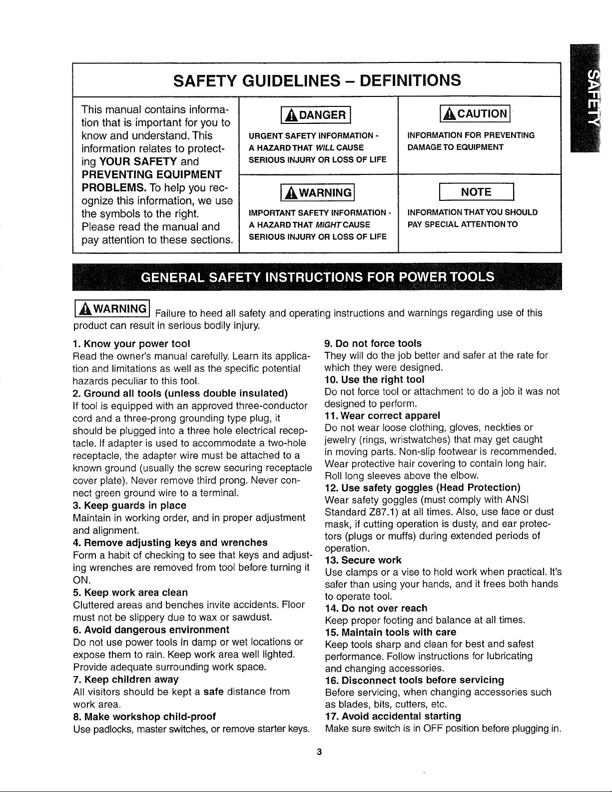
SAFETY GUIDELINES- DEFINITIONS
This manual contains informa-
tion that is important for you to
know and understand. This
information relates to protect-
ing YOUR SAFETY and
URGENT SAFETY INFORMATION -
A HAZARDTHAT WILL CAUSE
SERIOUS INJURY OR LOSS OF LIFE
IADANGER l
PREVENTING EQUIPMENT
PROBLEMS. To help you rec-
ognize this information, we use
the symbols to the right.
Please read the manual and
pay attention to these sections.
I_,WARNING
Failure to heed all safety and operating instructions and warnings regarding use of this
IMPORTANT SAFETY INFORMATION -
A HAZARD THAT MIGHTCAUSE
SERIOUS INJURY OR LOSS OF LIFE
I_WARNING]
product can result in serious bodily injury.
1. Know your power tool
Read the owner's manual carefully. Learn its applica-
tion and limitations as well as the specific potential
hazards peculiar to this tool.
2. Ground all tools (unless double insulated)
If tool is equipped with an approved three-conductor
cord and a three-prong grounding type plug, it
should be plugged into a three hole electrical recep-
tacle. If adapter is used to accommodate a two-hole
receptacle, the adapter wire must be attached to a
known ground (usually the screw securing receptacle
cover plate). Never remove third prong. Never con-
nect green ground wire to a terminal.
3. Keep guards in place
Maintain in working order, and in proper adjustment
and alignment.
4. Remove adjusting keys and wrenches
Form a habit of checking to see that keys and adjust-
ing wrenches are removed from tool before turning it
ON.
5. Keep work area clean
Cluttered areas and benches invite accidents. Floor
must not be slippery due to wax or sawdust.
6. Avoid dangerous environment
Do not use power tools in damp or wet locations or
expose them to rain. Keep work area well lighted.
Provide adequate surrounding work space.
7. Keep children away
All visitors should be kept a safe distance from
work area.
8. Make workshop child-proof
Use padlocks, master switches, or remove starter keys.
I CAUT'ONI
INFORMATION FOR PREVENTING
DAMAGE TO EQUIPMENT
I NOTE I
INFORMATION THAT YOU SHOULD
PAY SPECIAL ATTENTION TO
9. Do not force tools
They will do the job better and safer at the rate for
which they were designed.
10. Use the right tool
Do not force tool or attachment to do a job it was not
designed to perform.
11. Wear correct apparel
Do not wear loose clothing, gloves, neckties or
jewelry (rings, wristwatches) that may get caught
in moving parts. Non-slip footwear is recommended.
Wear protective hair covering to contain long hair.
Roll long sleeves above the elbow.
12. Use safety goggles (Head Protection)
Wear safety goggles (must comply with ANSI
Standard Z87.1) at all times. Also, use face or dust
mask, if cutting operation is dusty, and ear protec-
tors (plugs or muffs) during extended periods of
operation.
13. Secure work
Use clamps or a vise to hold work when practical. It's
safer than using your hands, and it frees both hands
to operate tool.
14. Do not over reach
Keep proper footing and balance at all times.
15. Maintain tools with care
Keep tools sharp and clean for best and safest
performance. Follow instructions for lubricating
and changing accessories.
16. Disconnect tools before servicing
Before servicing, when changing accessories such
as blades, bits, cutters, etc.
17. Avoid accidental starting
Make sure switch is in OFF position before plugging in.
18. Use recommended accessories
Consult the owner's manual for recommended
accessories and follow the instructions. The use of
improper accessories may cause hazards.
19. Never stand on tool
Serious injury could occur if the tool is tipped or if
the cutting tool is accidentally contacted. DO NOT
store materials above or near the tool making it nec-
essary to stand on the tool to reach them.
20. Check damaged parts
Before further use of the tool, any guard or other
part that is damaged should be carefully checked to
ensure that it will operate properly and perform its
intended function. Check for alignment of moving
parts, binding of moving parts, breakage of parts,
mounting, and any other conditions that may affect
its operation. A guard or any other part that is
damaged should be properly repaired or
replaced.21. Direction of feed
Feed work into a blade or cutter AGAINST the
direction of rotation of the blade or cutter only.
22. Never leave tool running unattended
Turn power OFF. DO NOT leave tool until it comes to
a complete stop.
23. Keep hands away from cutting area
24. Store idle tools
When not in use, tools should be stored in dry, high
or locked-up place - out of reach of children.
25. Do not abuse cord
Keep cord away from heat, oil and sharp edges.
26. Outdoor extension cords
When tool is used outdoors, use only extension
cords suitable for use outdoors and so marked.
27. Never use in an explosive atmosphere
Normal sparking of the motor could ignite fumes,
flammable liquids, or combustible items.
28. Drugs, alcohol, medication
DO NOT operate tool while under the influence of
drugs, alcohol, or any medication.
Read and Understand this instruction book
completely BEFORE using this product.
1. Always wear eye protection that complies with ANSI
Standard Z87.1.
2. Noise levels vary widely with location. To avoid pos-
sible hearing damage, wear ear plugs or ear muffs
when using your router table for long periods of time.
3. For dusty operations, wear a dust mask along
with safety goggles.
4. Follow the instructions in your router owner's manual.
5.L_'WARNINGJ Vibrations, caused by the router
during use, can cause fasteners to become loose.
Before use and periodically during use, check all
fasteners to make sure that all are tight and secure.
6. Do not use this product until all assembly and instal-
lation steps have been completed. Make sure you have
read and understood all safety and
operational instructions in this manual and the
router owner's manual.
7. Make sure that the router bit is properly positioned
and clamped in the router before making any cuts.
8. Do not use the router table as a workbench or work
surface. Doing so may damage it, causing it
to be unsafe to use. A workbench should be used
for this purpose.
9. This product is designed for cutting flat workpieces.
Do not cut or attempt to cut workpieces that are not
flat.
10.This product is designed for cutting wood
workpieces only. Do not use to cut metal or other non-
wood materials.
11.The use of auxiliary in-feed and out-feed
supports is strongly recommended when routing long
workpieces. Otherwise those workpieces can cause
the router table to tip over.
12. Keep hands clear of the router bits and working
area.
13. Make and use a push stick to move small
workpieces across the cutting area.
14. Clean the router after use. The use of a wet/dry vac
or vacuum equipment is recommended.
15. Always make sure that work surface of the router
table is clean and free from dust, chips, and foreign
particles that can interfere with the cut you are
going to make. The use of a wet/dry vac or vacuum
equipment is recommended.
16. Check the function of the guard before each use.
Remove all dust, chips, and any other foreign parti-
cles that can affect its function.
17. '_WARNINGI Never put your fingers under the
overhead guard when the router is plugged into an
electrical outlet or when the router bit is rotating.
18. Always use the fence to guide the workpiece.
19. Always feed the workpiece AGAINST the rotation
of the cutter or router bit.
20. Router bits are extremely sharp; be extra careful
when handling and using them.
21. Make sure that the router bits being used are sharp
or have been properly resharpened. This will permit
fast, efficient, and SAFE routing.
22. Some routers, when positioned in an upside down
position (such as on a router table), will drop
or fall out of the router base when the base clamp is
loosened to adjust height or depth of cut. Therefore, it
is extremely important to support the router from
below when making these adjustments or whenever
the base clamp is loosened.
23. Always look under the router table at the router
switchboxwhenturningtherouterONorOFF.DO
NOTtouchanythingbuttheswitchboxwhendoing
this.NEVERreachundertheroutertableforanyrea-
sonwhentherouterisrunning,excepttoturnit OFF.
I
A
24.[ WARNING J Before making any cut, make
sure the router is turned OFF, the router bit is not
rotating, and the power cord is unplugged from the
electrical outlet. Then, make absolutely sure that the
overhead guard clears the router bit and the work-
piece. A trial pass, with the router turned OFF and the
router bit not turning, is strongly recommended.
25.l _WARNINGJ Never leave the router table
unattended while the router is running. Turn the router
OFF before leaving the router table for any reason.
I
26. If ANY of the parts is missing, DO NOT attempt
to assemble, install, or use your router table until the
missing parts have been found or replaced and your
router table has been properly and correctly assem-
bled per this manual.
/ I
27.[ _L, DANGER JNever use the floor stand as a
ladder and DO NOT stand on the router table.
Your Craftsman Router Table comes with the following:
• A unique 4" high unitized fence with fence guides that
provide parallel movement.
• Rulers molded into the table top that provide fast
and accurate fence adjustment for making the
following items:
- Tenons
- Sliding dovetail joints
- Tongue & groove joints
- Face cuts
• The unique fence also allows you to perform these
additional routing operations:
9-26478 Craftsman Router Table Floor Stand,
places router table at a convenient working height,
has adjustable floor levelers, and two steel shelves
for storage.
9-25468 Craftsman Guide Master RouterTable Push
Shoe, aids in push shoe and hold down operations,
accurate measurement and router table set-up,
transforms into a miter gauge, and gives quick set-up
for 1/2" sliding dovetail joints.
9-25333 Craftsman Industrial Router Adapter Plate,
for mounting non-Craftsman 1/4" and 1/2" reuters to
- Veining
- Fluting
- Making crown molding
- Making cuts up to 2-1/2" from the edge of the
workpiece toward the center of the workpiece
• A specially designed push block with a quick clamp
that can clamp work pieces up to 4" wide, for end grain
or edge routing.
• An accurate jointing fence that is quickly adjustable to
the proper depth of cut.
• A dust collector port on the fence to which most 2-1/2"
wet/dry vac hoses can be attached.
the router table. The holes for mounting the router
must be located and drilled by the user. The fasteners
for mounting the router to the adapter plate are not
included and must be obtained separately.
9-26478 Craftsman Router Table Floor Stand,
places router table at a convenient working height,
has adjustable floor levelers, and two steel shelves
for storage.
Refer to Parts List on page 19.
• /AI[jIAWARNINGj If ANY of the parts is missing,
DO NOT attempt to assemble, install, or use your
router table until the missing parts have been
found or replaced, and your router table has been
properly and correctly assembled per this manual.
• Contact your local Sears Retail Outlet for missing or
replacement parts.
• In order to simplify handling and to minimize any
damage that may occur during shipping, your router
table comes unassembled.
• Separate all parts from the packaging materials and
check each part against the illustrations and
the parts list at the end of this manual, to make
sure that all parts have been included. Do this before
discarding any of the packaging material.
5
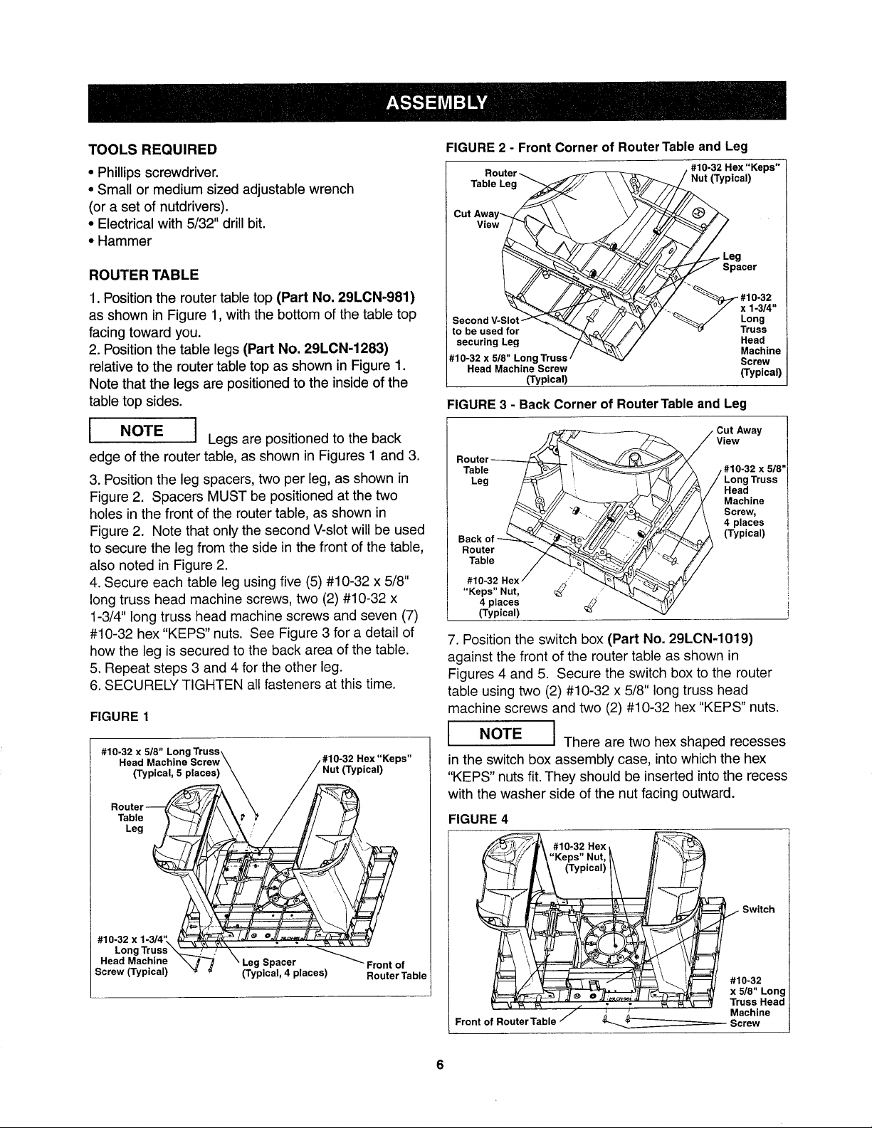
TOOLS REQUIRED
• Phillips screwdriver.
° Small or medium sized adjustable wrench
(or a set of nutdrivers).
° Electrical with 5/32" drill bit.
• Hammer
ROUTER TABLE
1. Position the router table top (Part No. 29LCN-981)
as shown in Figure 1, with the bottom of the table top
facing toward you.
2. Position the table legs (Part No. 29LCN-1283)
relative to the router table top as shown in Figure 1.
Note that the legs are positioned to the inside of the
table top sides.
B
l
I NOTE I Legs are positioned to the back
edge of the router table, as shown in Figures 1 and 3.
3. Position the leg spacers, two per leg, as shown in
Figure 2. Spacers MUST be positioned at the two
holes in the front of the router table, as shown in
Figure 2. Note that only the second V-slot will be used
to secure the leg from the side in the front of the table,
also noted in Figure 2.
4. Secure each table leg using five (5) #10-32 x 5/8"
long truss head machine screws, two (2) #10-32 x
1-3/4" long truss head machine screws and seven (7)
#10-32 hex "KEPS" nuts. See Figure 3 for a detail of
how the leg is secured to the back area of the table.
5. Repeat steps 3 and 4 for the other leg.
6. SECURELY TIGHTEN all fasteners at this time.
FIGURE 1
Head Machine Screw\ /#10-32 Hex r.eps"
Router_ \(Typical' 5 places)k_ / ///_ Nut (Typmal)
Table _--_'_// \ k_' _ / _'/ /_
•e,
FIGURE 2 - Front Corner of Router Table and Leg
Router _
Table Leg _/ \\\\
Cut Away_\ "
_///fY 7/I'7" Leg
10-32 Hex "Keps" ]
ical) /
Spacer
View_
_k_Y-. 7 x 1-3/4"
Second V-Slot-_'_;_._ _ ///
to be used for _ik_/'/ J
securing Leg _'
#10-32 x 5/8" Long Truss /
Head Machine Screw
(Typical)
/ "_ Truss
FIGURE 3 - Back Corner of Router Table and Leg
Table
Leg
Router
Table
#10-32 Hex ,
"Keps" Nut,
4 places
(Typical)
7. Position the switch box (Part No. 29LCN-1019)
against the front of the router table as shown in
Figures 4 and 5. Secure the switch box to the router
table using two (2) #10-32 x 5/8" long truss head
machine screws and two (2) #10-32 hex "KEPS" nuts.
I
I
I NOTE I There are two hex shaped recesses
in the switch box assembly case, into which the hex
"KEPS" nuts fit. They should be inserted into the recess
with the washer side of the nut facing outward.
FIGURE 4
#10-32 Hex t
'Keps" Nut, _ H/
.10-32
/v -_ Long
Head
Machine
Screw
(Typical)
Cut Away
View
#10-32 x 5/8'
Long Truss
Head
Machine
Screw,
4 places
(Typical)
-32xl- _ k_
I #10-32 x 5/8" LongTruss\ ,,.
#1°LongT-uss .; " _
Head Mac_F" _ \ Leg Spacer . _ Front of
_crew (=yp=cai) '_ _ (Typmal, 4 places) RouterTable
(Typical)/_ l/ _,
- _ _ Switch#10-32
Front of Router Table _--....___ Screw
/
6
x 5/8" Long
Truss Head
Machine
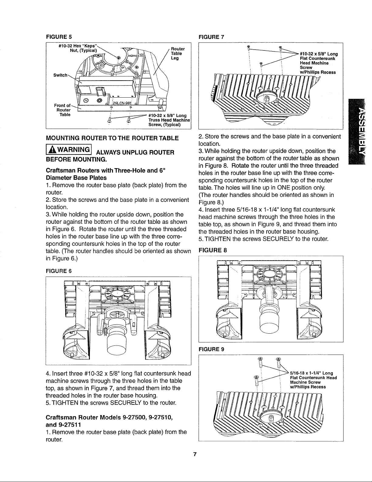
FIGURE 5 FIGURE 7
#10-32 Hex "Keps"_
Nut, (Typical)_ -_,- _ / Router
_,_ _ --///_ \\/ Leg
_ _ ,_/ / Table
Switch_ "_
Front of--.
Router
Table
#10-32 518" Long
Truss Head Machin
Screw, (Typical)
_ #10-32 x 518" Long
i _ Flat Countersunk
i _ i Head Machine
Y ! Screw
'_ '_ '_ w/Phillips Recess
MOUNTING ROUTER TO THE ROUTER TABLE
I WARNINGI ALWAYSUNPLUGROUTER
BEFORE MOUNTING.
Craftsman Routers with Three-Hole and 6"
Diameter Base Plates
1. Remove the router base plate (back plate) from the
router.
2. Store the screws and the base plate in a convenient
location.
3. While holding the router upside down, position the
router against the bottom of the router table as shown
in Figure 6. Rotate the router until the three threaded
holes in the router base line up with the three corre-
sponding countersunk holes in the top of the router
table. (The router handles should be oriented as shown
in Figure 6.)
FIGURE 6
2. Store the screws and the base plate in a convenient
location.
3.While holding the router upside down, position the
router against the bottom of the router table as shown
in Figure 8. Rotate the router until the three threaded
holes in the router base line up with the three corre-
sponding countersunk holes in the top of the router
table. The holes will line up in ONE position only.
(The router handles should be oriented as shown in
Figure 8.)
4. Insert three 5/16-18 x 1-1/4" long flat countersunk
head machine screws through the three holes in the
table top, as shown in Figure 9, and thread them into
the threaded holes in the router base housing.
5.TIGHTEN the screws SECURELY to the router.
FIGURE 8
i
4. Insert three #10-32 x 5/8" long flat countersunk head
machine screws through the three holes in the table
top, as shown in Figure 7, and thread them into the
threaded holes inthe router base housing.
5. TIGHTEN the screws SECURELY to the router.
Craftsman Router Models 9-27500, 9-27510,
and 9-27511
1. Remove the router base plate (back plate) from the
router.
FIGURE 9
7
x 1-1/4" Long
Flat Countersunk Head
i Machine Screw
', w/Phillips Recess
 Loading...