

Craftsman 17125490 Owner’s Manual
Save This Manua!_
For Future Reference
owners
manual
MODEL NO.
171.25490
CAUTION:
READ ALL
INSTRUCTIONS
CAREFULLY
CRRFTSMRH
INDUSTRIAL ROUTER TABLE
• assemb y
, operatinq
Sold bY SEARS. ROEBU(_KiAND CO., CH|CAGO,_i 6068_, U.S.A.
_ _ _..... _ .... L
Printed In U.S.A.
49LCN-39
WARNING: FAILURE TO HEED ALL SAFETY AND OPERATING INSTRUCTIONS AND WARNINGS REGARDING UI_tEI
OF THIS PRDDUCT CAN RESULT IN SERIOUS BODILY INJURY. ° !
GENERAL SAFETY INSTRUCTIONS
FOR POWER TOOLS
1. KNOW YOUR POWER TOOL
Read the owner's manual carelulty. Learn _ISapplicalion and
hmitations as we!l as the spot=tic potential hazards peculiar
Io thrs tool.
2. GROUND ALL TOOLS (UNLESS DOUBLE
INSULATED)
If tool is equipped with an _pproved 3-conductor cord end a
3-prong grounding type plug to tJ_.the proper grounding type
receptacle. The green cor:_,,ctor in the card ts the ground-
0ng wire. Never connect me green w=re to a lwe terminal.
3. KEEP GUARDS IN PLACE
in working order, and _nprope:"ad}ustmenI ar,d ahgnmenl.
4. REMOVE ADJUSTING KEYS AND WRENCHES
Form habit of checking tc see that keys and adjusbng
wrenches are removed 1ramtool before turning ]t on.
5. KEEP WORK AREA CLEAN
Cluttered areas ana ber_cnes _rvlte a-"c;cents. Floor musl
not be slippery due lc wax or sawdust
6. AVOID DANGEROUS ENVIRONMENT
Don'.*. use power Iools iB damp or wet IocalJons or expose
them to rain Keep work area welt i_ghled Pruvicle adequale
surrourld_n§ work space.
7. KEEP CHILDREN AWAY 19.
All vrsilors ,Should be I_ept _,safe d_tance from work area.
8. MAKE WORKSHOP KID-PROOF -
- with padlocks, maste, s_ltcnes, or 13yremov;ng starlet
, ,_ keYS.
13. SECURE WORK
Use clamps or a wse ,'o hold work when practical. Its safer
than using Four hand trees both hands to operate tool.
14. DON'T OVERREACH
Keep proper fooling arid balance at all limes.
15. MAINTAIN TOOLS WITH CARE
Keeps tools sharp and clean for best and safest parlor-
manta. Follow instructio'ls for lubricalmg and changing
accessorieS,
16, DISCONNECT TOOLS
before servicing: when cnaqcjlng accessor,,es such as blades,
bits cutters: etc
17. AVOID ACCIDENTAL STARTING
Make sure swllch is in "OFF' position belore p!ugglng ,'n,
18.
USE RECOMMENDED ACCESSORIES
Consult the owners manua_ for recommenOed., accessories.
Follow me mstruclions that accompany the accessories. The
use of improper accessones may cause hazards
NEVER STAND ON TOOL
Ser=ous iniur y could occur =fthe tool =s tipped Or If the cuTlicg
tool is accidentally contacted.
D3 not slore matenals above or near lhe loot sucl_that if is
necessary tQsiand on the Iooi to reach lhem
9. DON'T FORCE TOOL 20,
It will do the job better anc saler at lhe rate for ',,.rh_chmtwas
designed.
10. USE RIGHT TOOL
Don't force tool or atta--'hmenl to do a job _tw_s not destgne-.,d ::-_.! age of pads. mounting, ard any other coqdihons that may
Ior. " . ." .
11. WEAR RIGHT APPAREL
Do not wear =oose clolh,ng 9loves. neckt,,es or j_,,ve_-y (nngs,
wnsl walches} to get caught _n moving o_rts. Nonshp !be;-
wear is recommenoea. Wear protect;re hair covering to
comaip long ham Roll long sleeves auove the elbow.
iz use
SAFETY GOGQLES (Head Protection)
Wear Safely goggles (must comply with ANS ZB71) at all
hmes Also use race or dusl mask if c,J.qlna oper_lion ,s
dusry ar_:d ear prole"tors '.lZtUgS br mutts) clu'_ing, exienae:l
, per! .otis o! oper,allon.
CHECK DAMAGED PARTS
Before turlher use oi the- tool a guard or other par';,that _s
damaged should be caretMiy checked tOensure thai it will
operate properly and pedo,'m its intended function. Check
for aligRment of mowng oar'.s, bind=rig otmoving parts, break-
affecl _[soperation A guard or other par1 thai is damaged
sh.ou!a ae properly repaired or replaced.
21. DIRECTION OF FEED
Feed _,ork inlo a blade or cutter agains,: the direction of
mtZ..hon el lhe b_ade or Cutter ony.
22.
NEVER LEAVE TOOL RUNNING UNNATTENDED
Turn bower off. Dont te_ve_tool unlil..Jl comes t¢ a complele
S_Op
• ALWAYS USE EYE PROTECTION
The operation or ah_' power tool can result in
foreign objects being thrown irrlothe eyes, which
can result in severe eye damage. Always wear
safety goggles before commencing power tool
operation. Safety goggles are available at Sears
retail or catalog stores.
.
KEEP HANDS CLEAR OF BITS, AND WORKING
AREA.
3. MAKE AND USE A PUSH STICK TO MOVE
SMALL WORKPIECES ACROSS THE CUTTING
AREA.
=
KEEP ROUTER CLEAN AFTER EVERY USE,
CLEAN SAW DUST OF THE ROUTER. (ALSO
BLOW OUT INSIDE)•
=
YOUR ROUTER TABLE IS PROVIDED WITH A
DUST COLLECTING ATTACHMENT. ALWAYS
USE SHOP VAC FOR ALL ROUTING OPERA-
TIONS,
NOTE: Motors used on wood-working toots are
particulaMy susc_ptibie to the accumula-
tion o1'sawdust and wood chips, and
Should be blown out, or "vacuumed",
frequently to prevent interference with
normal me;or ventilation.
.
CHECK FUNCTION OF GUARD BEFORE EACH
USE. REMOVE ALL DUST AND CHIPS FROM
GUARD AREA AS NEEDED TO MAINTAIN
GUARD FUNCTION,
11.
WHEN END CUTTING ON WORKPIECES 4" WIDE
OR LESS, CLAMP AND HOLD AND FEED THE
WORKPIECE WITH THE PUSH BLOCK USING
BOTH HANDS AS SHOWN IN FIG, #25. KEEP
FINGERS CLEAR OF BIT WHEN MOVING WORK
PIECE ACROSS THE CUTTING AREA.
12.
ROUTER BITS ARE EXTREMELY SHARP,
Be exlra carefu; when working around them,
13.
SOME ROUTERS WHEN USED IN AN UPSIDE
DOWN POSITION SUCH AS ON A ROUTER
TABLE WILL FALL (OR DROP) OUT OF THE
ROUTER BASE WHEN THE BASE CLAMP IS
LOOSENED, IT IS THEREFORE ABSOLUTELY
NECESSARY TO SUPPORT THE ROUTER
MOTOR FORM BELOW WHEN THE BASE
CLAMP IS LOOSENED TO MAKE ADJUST
MENTS, OR FOR ANY OTHER REASON.
14.
ALWAYS LOOK UNDER THE TABLE AT THE
SWITCH WHEN TURNING THE ROUTER ON/OFF
AND TOUCH NOTHING BUT THE SWITCH.
NEVER REACH UNDER THE TABLEWHEN
ROUTER IS RUNNING FOR ANY OTHER
REASON.
NOTE:
it is far safer and convenient to use a "Sears
Craftsman 925C60 Router Table Switch
Package". This switch provides a key
operated ON/OFF button WhiCh allows very
fast and easy access when and if it becomes
necessary to turf, the router "OFF" quicldy.
The key can be removed to render the
switcM inoperable to unauthorized people.
7,
NEVER PUT YOUR FINGERS UNDER THE
GUARD WHEN THE ROUTER IS PLUGGED IN.
B,
ALWAYS USE THE ROUTER TABLE FENCE
TO GUIDE THE WORK. DO NOT WORK
FREEHAND.
When using the pilot type bits, keep the fences as
close to the pilot aspossible to provide additional
backup' and additional guidance and to avoid "
chances of an accident and possible personal
injury.
=
ALWAYS USE THE STARTING PIN AND
PILOTED BITS FOR FREE HAND ROUTING
IRREGULAR SHAPED WORKPIECES.
10,
ALWAYS FEED AGAINST THE ROTATION OF
THE CUTTER WHEN ROUTING ON THE
ROUTER TABLE,
15.
ONCE GUARD IS INSTALLED FOR ROUTING,
DO NOT REMOVE FOR ANY REASON.
MOUNT ROUTER TABLE FIRMLY AND SE-
16.
CURELY TO A WORK SURFACE BEFORE USE.
FAILURE TO DO SO COULD CAUSE TABLE TO
TIP OVER OR SLIDE DURING OPERATION
RESULTING tN PROPERTY DAMAGE AND/OR
SERIOUS BODILY INJURY,
17.
WARNING
BEFORE MAKING ANY CUT, UNPLUG ROUTER
AND MAKE ABSOLUTELY SURE THAT THE
GUARD CLEARS THE ROUTER BIT AND IS
FUNCTIONING NORMALLY.
18.
WARNING:
ROUTER VIBRATIONS SOMET;MES CAN
CAUSE FASTENERS FOR THE TABLE, THE -:
ROUTER AND THE UNITI2ED FENCE TO GET
LOOSEI PERIODICALLY CHECK FASTENERS
TO MAKE SURE THEY ARE TIGHT AND
SECURE.
INTRODUCTION
How otlen have you needea a large guiclingsurface on a
muter table? Your Sears Craftsman Industrial Router
Table wilh Unitized Fence comes with:
a. A unique 4" high unitized fence designed to
assist end grain routingfor making tenons,
sliding dovetails and tongue and groove joims
along with most edge and lace culling operations.
b. A specially designed pusMblock witMquick clamp for
back up and clamp;rig boards up to 4" wictthfor end
grain routing.
c. An accurate and quick adjusting jointing fence adjust-
able to proper jointing depth of cut.
d. A unitized lence designed to enable routing opera-
tions like grooving; Iluting; veining: crown molding etc.
up to 2 V2"away lrom the edge toward the middle of
the board.
UNPACKING AND CHECKING CONTENTS
e, Dust collecting attachment for most shop vac hook
ups.
To increase the work surface of your muter table, "Sears
Craftsman 925212 Industrial Roular Table Extensions"
are available as an optional produ= from Sears,
In order to simplifyhandling and minimize any damage
that might occur during shipment, your new rouler table
is packaged unassembled. We know you are anxious to
see w_al your new tool will do, but a few minutes spent
now carefully reading the following instructions, will
result in less frustration and more enjoyable operation
later.
Start bychecking and accounting for all the loose paMs.
If any parrs are missing, contact your local Sears retail or
catalog outlet for replacement.
WARNING: YOU MUST READ AND UNDERSTAND
ALL THE INSTRUCTIONS COMPLETELY BEFORE
ATTEMPTING TO ASSEMBLE AND OPERATE YOUR
ROUTER AND ROUTER TABLE.
ASSEMBLY
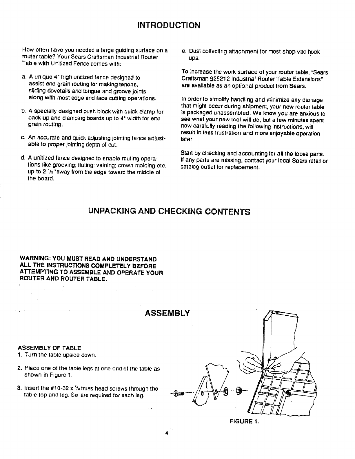
ASSEMBLY OF TABLE
1. Turn _he table upside clown.
2. Place one of the table legs al one end of the table as
shown in Figure 1.
3. Insert the #10-32 x %truss heacl screws through the
table lop and leg. Six are required for each leg.
FIGURE 1.
screw. The lock washers should be against the
inside ol the leg.
5. Repeat for the remaining leg.
8. Turn the table righl side up and tighten all 12 screws
and nuls with a wrench or pliers.
ASSEMBLY OF THROAT PLATE TO TABLE
four #10--32 stop nuts 1osecure the throat plate to
the table, as shown in Figure 5. Tighten securely.
1. Assernl31e four #10-32 x % panhead screws and four
#10-32 stop nuts to table as shown in Figure 2,
NOTE: After a low turns of the screw, resistance of
further turning wilt be experienced---this is
normal. Do not tighten completely: just enough
so screws protrude through nut.
#10-32 Stop nut Top of Talkie
#10-32 x % Panhead
Screw
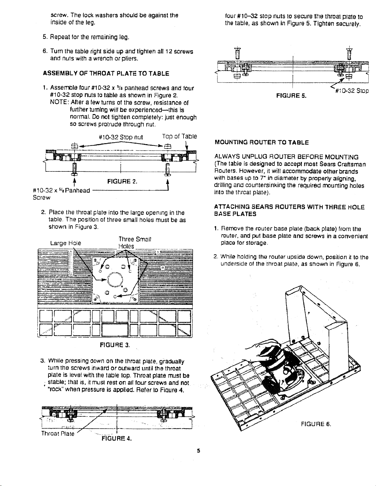
2. Place the throat plate into 1he large opemng in the
table. The position of three small holes must be as
shown in Figure 3.
Large Hole
Three Small
Holes
FIGURE 5.
MOUNTING ROUTER TO TABLE
ALWAYS UNPLUG ROUTER BEFORE MOUNTING
(The table is designed to accept most Sears Craftsman
Routers. However, i1will accommodate other brancls
with bases up to 7" in diameter by properly aligning,
drilling and countersinking the required mounting holes
into the thrcat plate).
ATTACHING SEARS ROUTERS WITH THREE HOLE
BASE PLATES
1. Remove the router base plate (back plate) from the
router, and put base plate an_ screws in a convenient
place for storage.
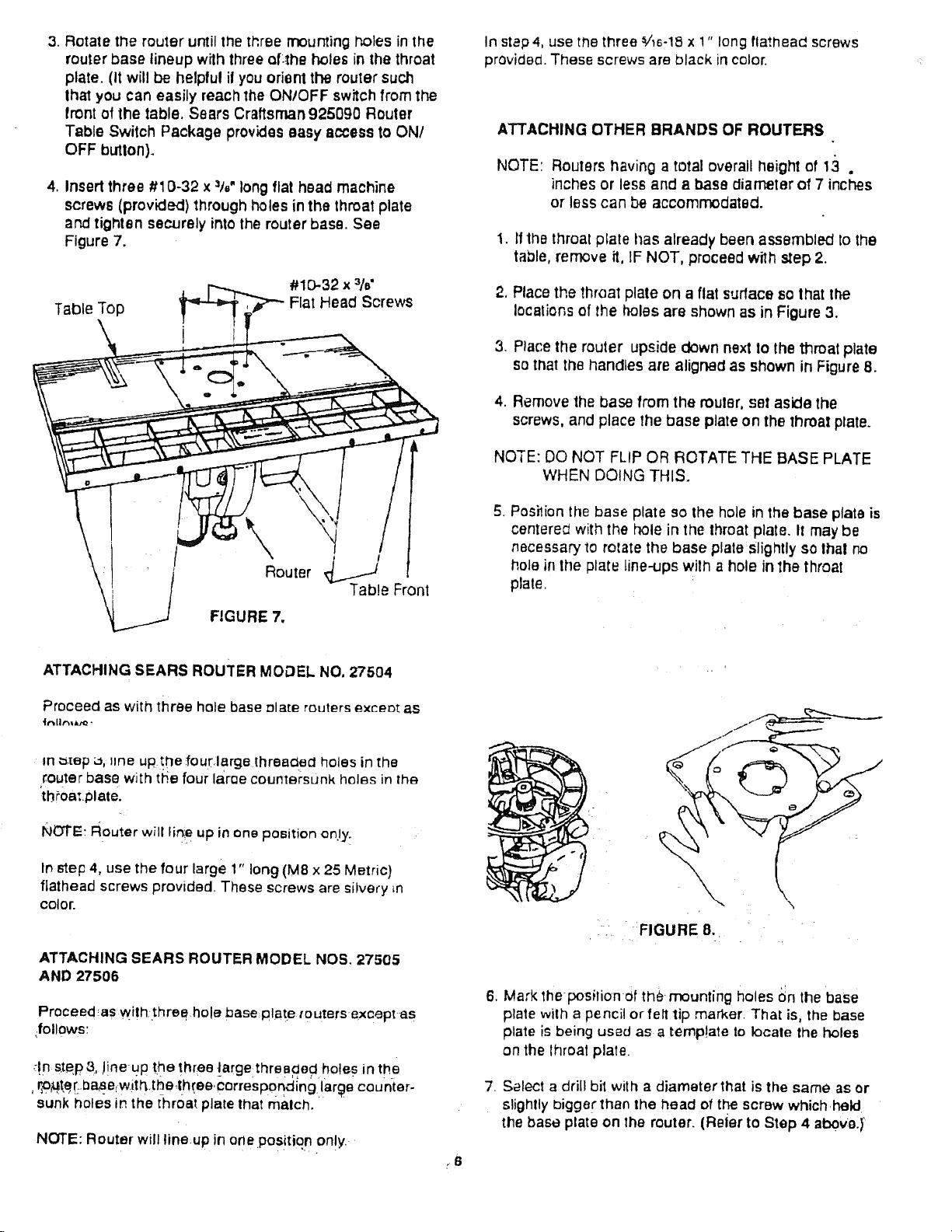
2. While holding the router upside down, position il to the
underside of the throat plate, as shown in Figure 6,
#I 0-32 Stop
L oOo__o.0oo _
LJ.__ uF-IOEOEOE
FIGURE 3.
3. While pressing sown on the lhroal plate, gradually
turn the screws inward or outward until the throat
plale is level with the taOle lop. Throat plate must be
; stable; thai is, it musl rest on all lout screws and not .
"rock"when pressure is al:_lied. Refer to Flours .4. '
I
i
f
Throat Plate " ......... "
[
FIGURE 4.
FIGURE 6.
3.RotatetherouteruntilthethreemountingI'_olesinthe
router base lineup with three af4he holes in the throat
plate. (It will be helpful il you orient the router such
Ihat you can easily reach the ONIOFF switch from the
front ofthe table. Sears Craftsman 925090 Router
Table Switch Package provides easy access to ON/
OFF button).
4, Insert three #10-32 x =t6"long flat head machine
screws (provided) through holes in the throat plate
and tighten securely,into the router base. See
Figure 7,
#10-32 x 3/€
Table Top
Flat Head Screws
In st_p 4, use the three _/'_s-18x !" long flathead screws
provided. These screws are black incolor.
ATTACHING OTHER BRANDS OF REUTERS
NOTE: Reuters having a total overall height of 13 .
inches or less and a base diameter of 7 inches
or less can be accommodated.
1.11the throal plate I_as already been assembled to the
table, remove it, IF NOT, proceed wilh step 2.
2. Place the throe1 plate on a flat surface so that the
locations of the holes are shown as in Figure 3.
3. Place the router upside down next to the throat plate
so that the handles are aligned as shown in Figure 8.
4. Remove the base from the rouler, set aside the
screws, and place the base plate on the lhroat plate.
NOTE: DO NOT FLIP OR ROTATE THE BASE PLATE
WHEN DOING THIS.
\
Router
Tab!e Front
FIGURE 7.
ATTACHING SEARS ROUTER MODEL NO. 27504
Proceed as with three hole base elate reuters exceot; as
in =.tap _, line uptrie lout:large threacted holes in the
router base with the four la.ri3e counler_unk hi31_s in lh_
ith£oat.platel
NOTE: Router willlin_.eup in one position on.ly.
In step 4, use the four large 1" long (MS x 25 Metric)
flathead screws provided. These screws are silvery in
color.
ATTACHING SEARS ROUTER MODEL NOS, 27505
AND 27506
Proceed_as with three hole base plate touters exoeptas
_follows:
!n step& !!ne-up me three targe;threa_ec! holes in the
r.o_terhaae.wi.tl3the,three,correspond ng lare counter-
sunk holes in the throat plate lhat rnalch.
NOTE: Router will lineup in one position only.
5. Posilion the base plate so the hole in the base plata is
centere_ withthe hole in the throat plate. It may be
necessary to relate the base plate slightly so Ihal no
hole in the plate line-ups with a hole in 1he throat
plate•
i
i';. " :FIGURE 8.
6, Mark the-positionOf tile.mounting holes On the base
plate with a pencil or felt tip marker. That is, the base
plate is being used as atemp!ate to locale the holes
on the lhroal plate.
7. Select a drill bll with a diameter that is the same as or
slightly Digger than the head of the screw which.held
the base plate on the router. (Reler to Step 4 above.)"
_S
 Loading...