

Craftsman 171.254790 Owner's Manual
Save This Manual
For Future Reference
owners
miii
MODEL NO.
171.254790
CAUTION:
READ ALL
NSTRUCTONS
CAREFULLY
iIffl
ROUTER TABLE
FULL FUNCTION/UNITIZED. FENCE
Sold by SEARS, ROEBUCK AND CO., Chicago, DL 60684 U.S.A.
6107 1
MADE IN U.S.A.
Prhted in U.S.A. 4-92
WARNING: FAILURE TO HEED ALL SAFETY AND OPERATING INSTRUCTIONS AND WARNINGS REGARDING USE
OF THIS PRODUCT CAN RESULT IN SERIOUS BODILY INJURY.
GENERAL SAFETY INSTRUCTIONS FOR POWER TOOLS
12.
KNOW YOUR POWER TOOL
1.
Read the owner's manual carefully. Learn its application and limitations as well as the specific potential
hazards peculiar to this tool.
GROUND ALL TOOLS (UNLESS
2.
DOUBLE INSULATED)
If tool is equipped with an approved 3-conductor cord
and a 3-prong grounding type plug, it should be plugged
into a three hole electrical receptacle. If adapter is used
to accommodate a two-prong receptacle, the adapter
wire must be attached to known ground, (usually the
screw securing receptacle cover plate). Never remove
third prong. Never connect green ground wire to a
terminal.
KEEP GUARDS IN PLACE
3.
in
working order, and in proper adjustment and
alignment.
REMOVE ADJUSTING KEYS
4.
AND WRENCHES
Form habit of checking to see that keys and adjusting
wrenches are removed from tool before turning
it
on.
KEEP WORK AREA CLEAN
5.
Cluttered areas and benches invite accidents. Floor
must not be slippery due to wax or sawdust.
AVOID DANGEROUS ENVIRONMENT
6.
Don't use power tools in damp or wet locations or
expose them to rain. Keep work area well lighted.
Provide adequate surrounding work space.
7.
KEEP CHILDREN AWAY
All visitors should be kept a safe distance from work
area.
8.
MAKE WORKSHOP KID-PROOF
-
with padlocks, master switches, or by removing
starter keys.
DON'T FORCE TOOL
9.
It
will do the job better and safer at the rate for which
it
was designed.
USE RIGHT TOOL
10.
Don't force tool or attachment to do a job it was not
designed for.
WEAR RIGHT APPAREL
11.
Do not wear loose clothing, gloves, neckties or jewelry
(rings,
wrist watches) to get caught in moving parts.
Nonslip footwear is recommended. Wear protective
hair covering to contain long hair. Roll long sleeves
above the elbow.
USE SAFETY GOGGLES (Head Protection)
Wear Safety goggles (must comply with ANS Z871)
at all times. Also, use face or dust mask if cutting
operation is dusty, and ear protectors (plugs or muffs)
during extended periods of operation.
SECURE WORK
13.
Use clamps or a vise to hold work when practical.
It's
safer than using your hand, frees both hands to
operate tool.
14.
DON'T OVERREACH
Keep proper footing and balance at all times.
15.
MAINTAIN TOOLS WITH CARE
Keeps tools sharp and clean for best and safest performance. Follow instructions for lubricating and
changing accessories.
16.
DISCONNECT TOOLS
before servicing; when changinq accessories such as
blades, bits, cutters, etc.
17.
AVOID ACCIDENTAL STARTING
Make sure switch is in OFF" position before plugging in.
18.
USE RECOMMENDED ACCESSORIES
Consult the owner's manual for recommended accessories.
the accessories. The use of improper accessories
may cause hazards.
19.
NEVER STAND ON TOOL
Serious -injury could occur if the tool is tipped or if
the cutting tool is accidentally contacted.
Do not store materials above or near the tool such
that it is necessary to stand on the tool to reach them.
20.
CHECK DAMAGED PARTS
Before further use of the tool, a guard or other part
that is damaged should be carefully checked to ensure that it will operate properly and perform its
intended function. Check for alignment of moving
parts, binding of moving parts, breakage of parts,
mounting, and any other conditions that may affect
its
operation. A guard or other part that is damaged
should be properly repaired or replaced.
21.
DIRECTION OF FEED
Feed work into a t,Iade or cuttor against the direction
of rotation of the blade or cutter only.
22.
NEVER LEAVE TOOL RUNNING
UNATTENDED
Turn. power
complete stop.
Follow the instructions that accompany
off. Don't
leave tool until it comes to a
-
GENERAL SAFETY INSTRUCTIONS FOR THE ROUTER TABLE
WITH UNITIZED FENCE.
ALWAYS USE EYE PROTECTION
1.
The operation of any power tool can result in for-
eign objects being thrown into the eyes, which can
result in severe eye damage. Always wear safety
goggles before commencing power.tool operation.
Safety goggles are available at Sears retail or catalog stores.
KEEP HANDS CLEAR OF BITS, AND WORKING
2.
AREA
MAKE AND USE A PUSH STICK TO MOVE
3.
SMALL WORKPIECES ACROSS THE CUTTING
AREA.
4.
KEEP ROUTER CLEAN
AFTER EVERY USE, CLEAN SAW DUST OFF
THE ROUTER. (ALSO BLOW OUT INSIDE).
YOUR ROUTER TABLE IS PROVIDED WITH A
5.
DUST COLLECTING ATTACHMENT. ALWAYS
USE SHOP VAC. FOR ALL ROUTING OPERATIONS REQUIRING USE OF FRONT SIDE OF
UNITIZED FENCE. (FRONT SIDE IS THE SIDE
WITH THE CRAFTSMAN LABEL).
NOTE: Motors used on wood-working tools are
particularly susceptible to the accumulation of sawdust and wood chips, and
should be blown out, or "vacuumed", frequently to prevent interference with normal motor ventilation.
CHECK FUNCTION OF GUARD BEFORE EACH
6.
USE. REMOVE ALL DUST AND CHIPS FROM
GUARD AREA AS NEEDED TO MAINTAIN
GUARD FUNCTION.
NEVER PUT YOUR FINGERS UNDER THE
7.
GUARD WHEN THE ROUTER IS PLUGGED IN.
ALWAYS USE THE ROUTER TABLEFENCE TO
8.
GUIDE THE WORK. DO NOT WORK FREE
-HAND.
When using pilot type bits, keep the fences as close
to the pilot as possible to provide additional backup
and additional guidance and to avoid chances of
an accident and possible personal injury.
ALWAYS FEED AGAINST THE ROTATION OF
9.
THE CUTTER WHEN ROUTING ON THE
ROUTER TABLE. FEED WORKPIECES IN THE
DIRECTION OF THE ARROW AS SHOWN ON
THE LABEL ON THE SIDE OF THE FENCE
BEING USED (WHEN FACING THE TABLE
FRONT).
WHEN END CUTTING ON WORKPIECES 4"
11.
WIDE OR LESS, CLAMP AND HOLD AND FEED
THE WORKPIECE WITH THE PUSH BLOCK
USING BOTH HANDS AS SHOWN IN FIG. #27.
KEEP FINGERS CLEAR OF BIT WHEN MOVING
WORKPIECE ACROSS THE CUTTING AREA.
NEVER PLACE YOUR HANDS LOWER THAN
THE TOP OF RETRACTABLE GUARD.
12.
ROUTER BITS ARE EXTREMELY SHARP.
Be extra careful when working around them.
SOME ROUTERS WHEN USED IN AN UPSIDE
13.
DOWN POSITION (SUCH AS ON A ROUTER
TABLE) WILL FALL (OR DROP) OUT OF THE
ROUTER BASE WHEN THE BASE CLAMP IS
LOOSENED. IT IS THEREFORE ABSOLUTELY
NECESSARY TO SUPPORT THE ROUTER
MOTOR FROM BELOW WHEN THE BASE
CLAMP IS LOOSENED TO MAKE ADJUSTMENTS, OR FOR ANY OTHER REASON.
14.
ALWAYS LOOK UNDER THE TABLE AT THE
SWITCH WHEN TURNING THE ROUTE.R
ON/OFF AND TOUCH NOTHING BUT THE
SWITCH. NEVER REACH UNDER THE TABLE
WHEN ROUTER IS RUNNING FOR ANY OTHER
REASON.
NOTE: It is far more safe and convenient to use
a "Sears Craftsman 25182 Router Table
Switch Package". This switch provides a
key operated ON/OFF button which allows
very fast and easy access when and if it
becomes necessary to turn the router
"OFF" quickly. The key can be removed
to render the switch inoperable to unautho-
rized people.
15.
ONCE BOTH GUARDS ARE INSTALLED FOR
ROUTING, DO NOT REMOVE THEM FOR ANY
REASON.
16.
MOUNT ROUTER TABLE FIRMLY AND
SECURELY TO A WORK SURFACE BEFORE
USE. FAILURE TO DO SO COULD CAUSE
TABLE TO TIP OVER OR SLIDE DURING OPERATION RESULTING IN PROPERTY DAMAGE
AND/OR SERIOUS BODILY INJURY.
WARNING:
17.
BEFORE MAKING ANY CUT, UNPLUG ROUTER
AND RETRACT GUARD TO MAKE ABSOLUTELY SURE THAT RETRACTABLE GUARD
CLEARS THE ROUTER BIT, AND THE GUARD
IS FUNCTIONING NORMALLY. SEE FIG. #19.
FOR ALL EDGE CUTTING AND END CUTTING
10.
OPERATIONS, USE FRONT SIDE OF UNITIZED
FENCE. USE BACK SIDE OF FENCE ONLY FOR
ROUTING OPERATIONS AWAYFROM EDGE
ON THE UNDERSIDE OF WORKPIECE SUCH AS
GROOVING; FLUTING; VEINING; CROWN
MOLDJNG ETC.
WARNING:
18.
ROUTER VIBRATIONS SOMETIMES CAN
CAUSE FASTENERS FOR THE TABLE, THE
ROUTER AND ThE UNITIZED FENCE TO QET
LOOSEI PERIODICALLY CHECK FASTENERS
TO MAKE SURE THEY ARE TIGHT AND
SECURE.
INTRODUCTION
e
How often have you needed a large guiding surface on
a router table? Your Sears Craftsman Router Table with
Unitized Fence comes with:
A unique 4" high unitized fence designed to assist
a.
for end grain routing for making tenons, sliding
dovetails and tongue and groove-joints along with
most edge and face cutting operations.
A specially designed push bloek with quick clamp
b.
for back up and clamping boards up to 4" width for
end grain routing.
An accurate and quick adjusting jointing fence
c.
adjustable to proper jointing depth of cut.
Reversing feature of unitized fence designed to
d.
enable routing operations like grooving; fluting;
veining; crown molding etc. up to 2 1/2" away from
the edge towards the middle of the board.
Two guards for operation on either side of the unitized fence.
f.
Dust collecting attachment for most shop vac. hook
ups.
If order to facilitate handling and minimize any damage
that might occur during shipment, your new routertable
is packaged unassembled. We know you are anxious
to see what your new tool will do, but a few minutes
spent now carefully reading the following instructions,
will result in less frustration and more enjoyable operation later.
Start by checking and acôounting for all the loose parts.
If
any parts are missing, contact your local Sears retail
or catalog outlet for replacement.
UNPACKING AND
CHECKING CONTENTS
Refer to Parts List on Page 16
WARNING
YOU MUST READ AND UNDERSTAND ALL THE INSTRUCTIONS COMPLETELY
ASSEMBLE AND OPERATE YOUR ROUTER! ROUTER TABLE.
6.
Turn the table right side up and tighten all 16
screws and nuts with a screwdriver and wrench or
pliers.
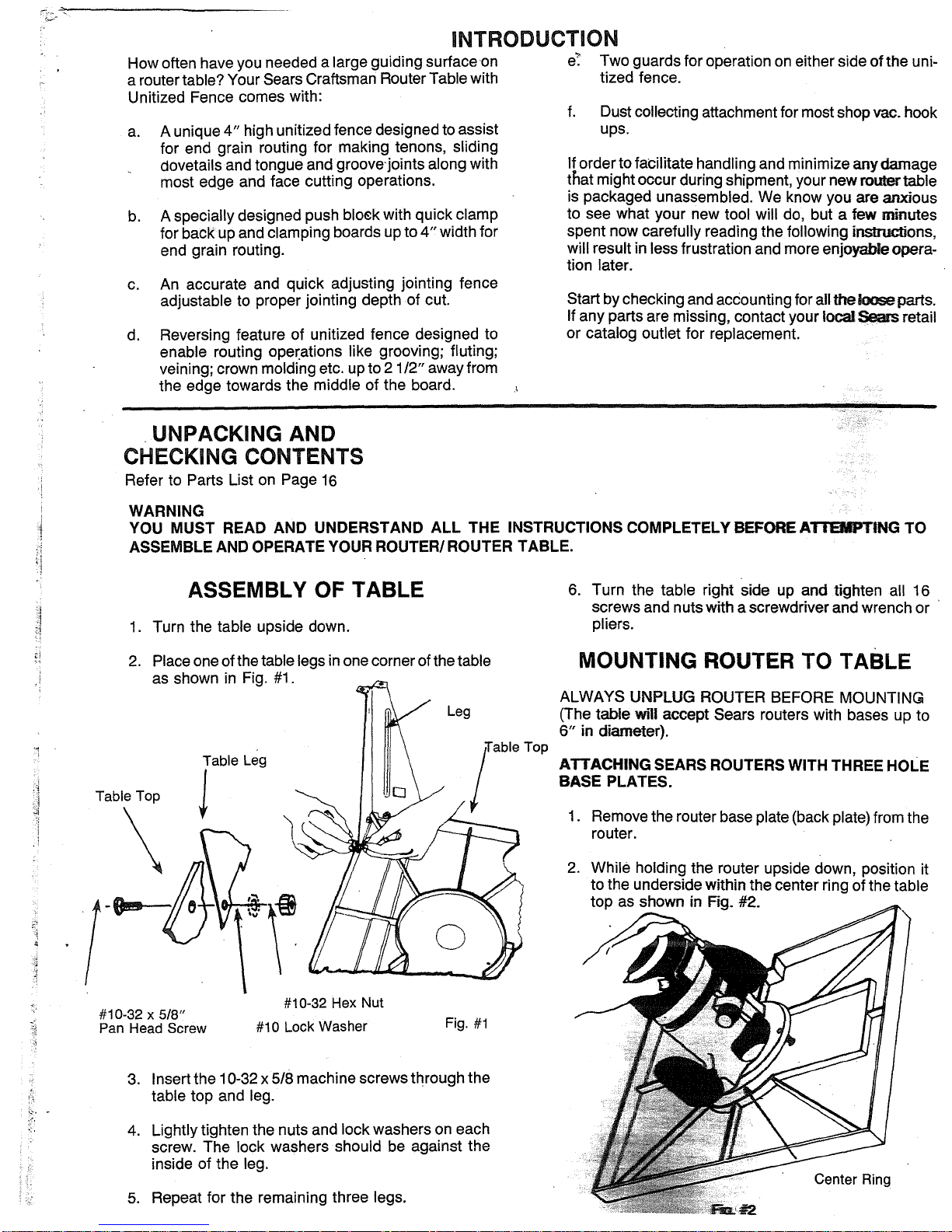
MOUNTING ROUTER TO TABLE
ALWAYS UNPLUG ROUTER BEFORE MOUNTING
(The table will accept Sears routers with bases up to
6" in diameter).
ATTACHING SEARS ROUTERS WITH THREE HOLE
BASE PLATES.
1.
Remove the router base plate (back plate) from the
router.
2.
While holding the router upside down, position it
to the underside within the center ring of the table
top as shown in Fig. #2.
1.
2.
Table Top
ASSEMBLY OF TABLE
Turn the table upside down.
Place one of the table legs in one corner of the table
as shown in Fig. #1.
Leg
BEFORE ATTTING
TO
#10-32
Pan Head Screw
5/8"
x
Insert the 10-32 x 5/8 machine screws through the
3.
table top and leg.
Lightly tighten the nuts and lock washers on each
4.
screw. The lock washers should be against the
inside of the leg.
Repeat for the remaining three legs.
5.
#10-32 Hex Nut
#10 Lock Washer
Fig. #1
Center Ring
--
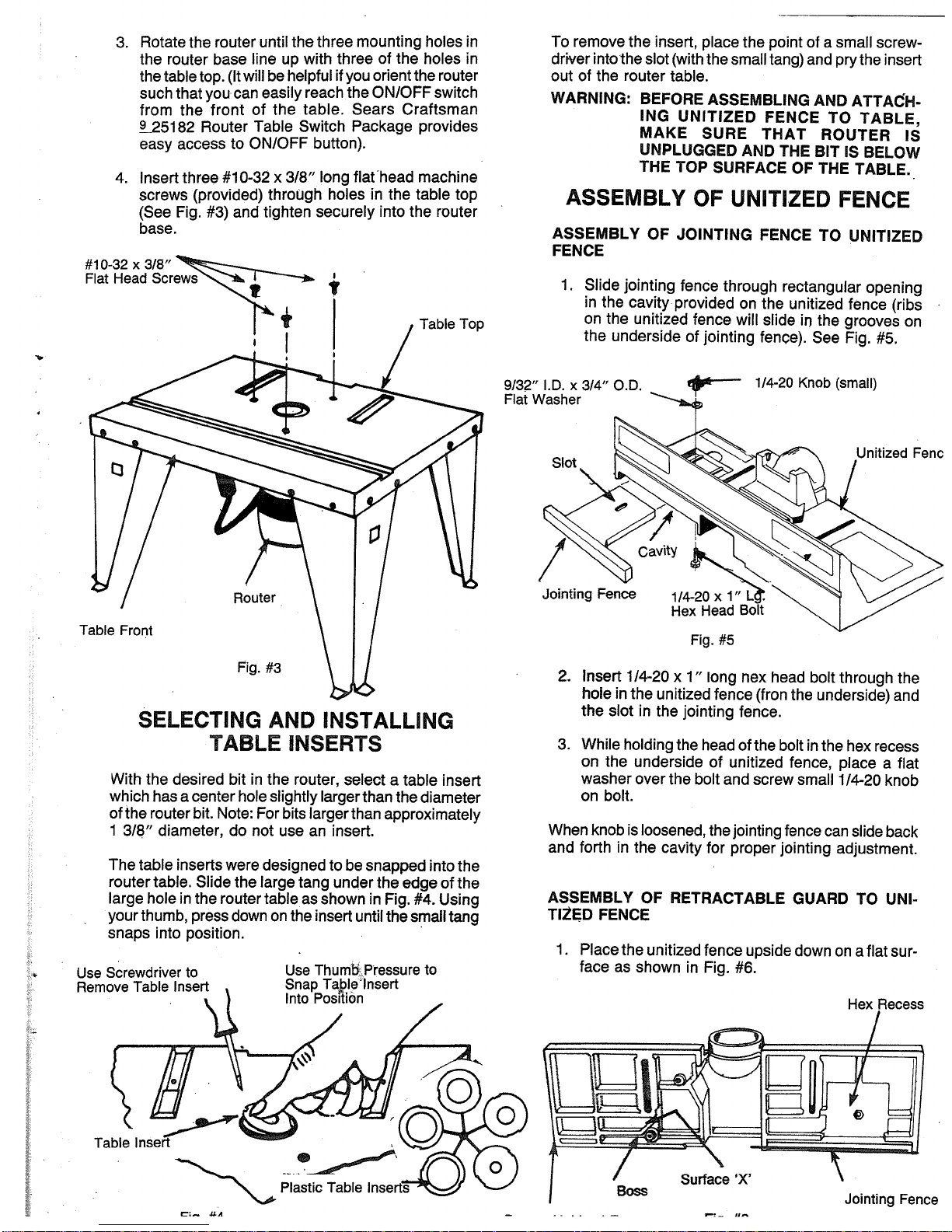
Rotate the router until the three mounting holes in
3.
the router base line up with three of the holes in
the table top. (It will be helpful if you orient the router
such that you can easily reach the ON/OFF switch
from the front of the table. Sears Craftsman
25182 Router Table Switch Package provides
easy access to ON/OFF button).
Insert three #10-32 x 3/8" long flat head machine
4.
screws (provided) throUgh holes in the table top
(See Fig. #3) and tighten securely into the router
base.
To remove the insert, place the point of a small screwdriver into the slot (with the small tang) and pry the insert
out of the router table.
WARNING: BEFORE ASSEMBLING AND ATTACH-
ING UNITIZED FENCE TO TABLE,
MAKE SURE THAT ROUTER IS
UNPLUGGED AND THE BIT IS BELOW
THE TOP SURFACE OF THE TABLE.
ASSEMBLY OF UNITIZED FENCE
ASSEMBLY OF JOINTING FENCE TO UNITIZED
FENCE
1.
Slide jointing fence through rectangular opening
in the cavity provided on the unitized fence (ribs
on the unitized fence will slide in the grooves on
the underside of jointing fence). See Fig. #5.
9/32"I.D.x3/4" O.D.
rii vvasnr
- 1/4-20 Knob (small)
Unitized Fenc
SELECTING AND INSTALLING
TABLE INSERTS
With the desired bit in the router, select a table insert
which has a center hole slightly larger than the diameter
of the router bit. Note: For bits larger than approximately
1
3/8" diameter, do not use an insert.
The table inserts were designed to be snapped into the
router table. Slide the large tang under the edge of the
large hole in the router table as shown in Fig. #4. Using
your thumb, press down on the insert until the small tang
snaps into position.
Use Screwdriver to
Remove Table Insert
Use Thumbs Pressure to
Snap TaIeinsert
Into Position
Fig. #5
2.
Insert 1/4-20 x 1" long flex head bolt through the
hole in the unitized fence (fron the underside) and
the slot in the jointing fence.
3.
While holding the head of the bolt in the hex recess
on the underside of unitized fence, place a flat
washer over the bolt and screw small 1/4-20 knob
on bolt.
When knob is loosened, the jointing fence can slide back
and forth in the cavity for proper jointing adjustment.
ASSEMBLY OF RETRACTABLE GUARD TO UNITIED FENCE
1.
Place the unitized fence upside down on a flat sur-
face as shown in Fig. #6.
Hex Recess
.iLA
,-- ',.
 Loading...