

Craftsman 17125450 Owner’s Manual
ModelNo,
171.25450
CRAFT$1VlAK
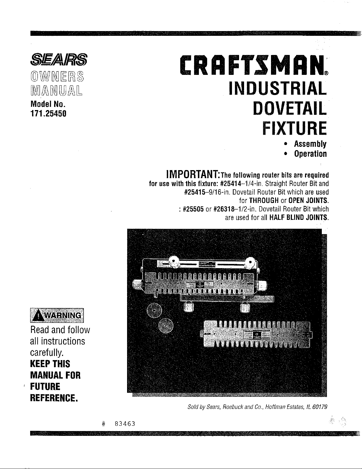
INDUSTRIAL
DOVETAIL
FIXTURE
• Assembly
• Operation
iMPORTANT;Thefollowingrouterbitsarerequired
for usewiththis fixture:#25414-1/4-in. Straight Router Bitand
#25415-9/16-in. DovetailRouter Bitwhich are used
for THROUGHor OPENJOINTS.
: #25505 or #26318-1/2-in. DovetailRouterBit which
are usedfor a!l HALFBLINDJOINTS.
Readandfollow
all instructions
carefully.
KEEPTHIS
MANUALFOR
' FUTURE
REFERENCE,
Sold by Sears,Roebuckand Co,, Hoffman Estates,IL 60179
# 83463
, i i
FAILURETO HEEDALLSAFETYANDOPERATINGINSTRUCTIONS
ANDWARNINGSREGARDINGUSEOF THISPRODUCTCANRESULT
IN SERIOUSBODILYINJURY
1) KNOWYOURPOWERTOOL
Readtheowner'smanualcarefully.Learnitsapplicationsand
Iimitatlonsaswell asthespecificpotentialhazardsparticularto
thistool.
2) GROUNDALLTOOLS(UNLESSDOUBLEINSULATED)
Iftoolis equippedwithanapproved3-conductorcordanda3-
pronggroundingtypeplug,itshouldbepluggedintoathreehole
electricalreceptaute.It adapteris usedtoaccommodateatwo-
prongreceptacle,theadapterwiremustbeattachedto known
ground,(usuallythescrewsecuringreceptaclecoverplate).
Neverremovethirdprong.Neverconnectgreengroundwireto a
terminal.
3) KEEPGUARDSINPLACE
--in workingorder,andinproperadjustmentandalignment.
4) REMOVEADJUSTINGKEYSANDWRENCHES
Forma habitof checkingtoseethatkeysandadjustingwrenches
areremovedfromtoolbeforeturningit on.
5) KEEPWORKAREACLEAN
Clutteredareasandbenchesinviteaccidents.Floormustnot be
slipperydoeto waxor sawdust.
6} AVOIDDANGEROUSENVIRONMENT
Donot usepowertoolsindamporwetlocationsorexposethornto
rain.KeepworkareawelIlighted.Provideadequatesurrounding
workspace.
7) KEEPCHILDRENAWAY
All visitorsshooktbekeptata safedistancefromworkarea.
B) MAKEWORKSHOPCHILD-PROOF
--with padlocks,masterswitches,or byremovingstarterkeys.
9) DONOTFORCETOOL
It willdothejob betterandsaferatthe rateforwhichitwas
designed.
10)USEAPPROPRIATETOOL
Donotforcetoolor attachmentto doajob forwhichitwasnot
designed.
11)WEARAPPROPRIATEAPPAREL
Donotwearlooseclothing,gloves,necktiesorjewelry(rings,
wristwatches)to getcaughtin movingparts.Nonslipfootwearis
recommended.Wearprotectivehaircoveringtocontainlonghair.
Rolllongsleevesel;Dyetheelbow.
12)USESAFETYGOGGLES(HeadProtection)
WearSafetyGoggles(mustcomptywith ANSIZ87.1) atalltimes.
Also,usefaceordustmaskif cuttingoperationis dusty,andear
protectors(plugsormuffs)duringextendedperiodsofoperation.
13)SECUREWORK
Useclampsora viseto holdworkwhenpractical,it'ssaferthan
usingyourhandandfreesbothhandsto operatetool.
14)DONOTOVERREACH
Keepproperfootingandbalanceatalltimes.
15)MAINTAINTOOLSWITHCARE
Keeptools sharpandc]eanfor bestandsafestperformance.Follow
instructionsfor lubricatingandchangingaccessories.
16)DISCONNECTTOOLSBEFORESERVICING
-when changingaccessoriessuchasblades,bits,cutters,etc.
17)AVOIDACCIDENTALSTARTING
Makesureswitchisin OFFpositionbeforepluggingin.
18)USERECOMMENDEDACCESSORIES
Consulttheowner'smanualfor recommendedaccessories.Follow
theinstructionsthataccompanytheaccessories.Theuseof
improperaccessoriesmaycausehazards.
19)NEVERSTANDONTOOL
Seriousinjurycouldoccur;fthetool Istippedorthecuttingtool is
accidentallycontacted.0o notstorematerialsaboveor nearthetool
thatwouldmakeit necessaryto standon thetoolto reachthem.
20)CHECKDAMAGEDPARTS
BeforefurtheruseofthetooI,aguardor otherpartthatis damaged
shouldbecarefullycheckedto ensurethatitwill operateproperly
andperformitsintendedfunction.Checkfor alignmentof racy(rig
parts,bindingofmovingparts,breakageof parts,mounting,andany
otherconditionsthat mayaffectitsoperation.Aguardorotherpart
thatisdamagedshouldbeproperlyrepairedorreplaced.
21)DIRECTIONOFFEED
Feedworkintoabladeorcutteronlyagainstthedirectionof rotation
ofthe bladeor cutter.
22)NEVERLEAVETOOLRUNNINGUNA'n'ENDED
Turnpoweroff. Donotleavetooluntilit comesto a completestop.
23)KEEPHANDSAWAYFROMCUT(1NGAREA
24)STOREIDLETOOLS
Whennotin use,toolsshouldbestoredindry,highorIocked-up
place---outof reachofchildren.
25)O0HOTABUSECORD
Keepcordawayfrom heat,oil,andsharpedges.
28)OUTDOOREXTENSIONCORDS
Whentoo!isusedoutdoors,useonlyextensioncordssuitablefor
useoutdoors,andso marked.
27)NEVERUSEINANEXPLOSIVEATMOSPHERE
Normalsparkingofthemotorcouldignitefumes,flarnmab;eliquids,
or combustibleitems.
28)DRUGS,ALCOHOL,MEDICATION
Donotoperatetoolwhile undertheinfluenceofdrags,alcohol,or
anymedication.
READANDUNDERSTANDTHISCOMPLETEINSTRUCTIONBOOK
BEFOREUSINGTHISPRODUCT
2
ADDITIONALSAFETYINSTRUCTIONSFORYOUR
INDUSTRIALDOVETAILFIXTURE
1) AlwaysweareyeprotectionthatcomplieswithcurrentANSI
StandardZ78A.
2) Noiselevelsvarywidely.Toavoidpossiblehearingdamage,wear
earpIugsor muffswhenusingtheDovetailFixturefor hoursata
time.
3) Wearadust maskalongwiththesafetygoggles.
4) Donotusethis DovetailFixturewith routerbitsor guide
bushingsotherthanthosespecifiedforthecuts beingmade.
5) FollowtheinstructionsinyourRouterOwnersManual.
6) Vibrationscausedbytherouterduringusecancausefasteners
to becomeloose.Beforeuseandperiodicallyduringusecheckall
fastenerstomakesurethattheyareagtightandsecure.
7) Donotusethis productuntilallassemblyinstallationstepshave
beencompleted,andyouhavereadandunderstandnitsafetyand
operationalinstructionsinthis manual,andtheRouterOwners
ManuaL
8) Makesurethattherouterbitis properlypositionedin therouter
sothatit doesnotcontacttheguidebushingorthetemplatewhen
cutting.
9) TheDovetailFixturemustbesecurelymountedtoaworkbench
or otherstablesurfacewheninuse.Thefrontof thebaseshould
overhangthe frontof theworkbenchbynomerethan1/4"to provide
clearancewhenclampingworkpiecestotheDovetailFixture.
10) DonotusetheDovetailFixtureasaworksurface.Doingsomay
causedamageto theDovetailFixture,whichcancauseitto beunsafe
to use.Aworkbenchshouldbeusedforthispurpose.
11)Thisproductis designedtocutflatworkpieces.Donotcutor
attempttocutworkpiecesthatarenotflat orthatareirregularly
shaped.
12)Thisproductis to beusedforcuttingwoodworkpiecesonly.Do
notusethisproducttocutmetaloranyothernon-woadmaterial.
13)Thisproducthasbeendesignedto cutworkpieceshaving
thicknessesof3/8"to 1".Donotuseforworkpiecesofanyother
thicknesses.
14)DonotclampanyworkpiecestotheDovetailFixtureormakeany
adjustmentsto theDovetailFixtureunlesstherouterhasbeenturned
off,the routerbitisnotturning,andthe Routerhasbeen
disconnectedfromtheelectricaloutlet.
15)Whensetting"lhe-dopth-ot-cut"oftherouterbit,makesurethat
theworkplaceis clampedto theDovetailFixturein sucha.manner
thattherouterbitdoesnotcutinto the Dovetailbasecausing
damagetoit orpassibleseriousinjurytoyou.
16) ALWAYSUNPLUGTHEROUTERFROMTHE
ELECTRICALOUTLETBEFOREINSTALLINGORREMOVINGROUTER
BITSFROMTHEROUTERANDWHENADJUSTINGTHECUTTING
DEPTHOFTHEROUTERBIT;ORWHENINSTALLINGORCHANGING
GUIDEBUSHINGS,
17)NEVERLiFTTHEROUTERUPWARDSWHENTHEROUTERiS
"ON",THEROUTERBITISROTATING,ANDTHEGUIDEBUSHINGiS
NEARORTOUCHINGTHETEMPLATE,BECAUSETHISWILLCAUSE
THEROUTERBITTOCUTINTOTHETEMPLATEANDDAMAGEIT.
INTRODUCTION
o Your Sears/Craftsmanindustrial DovetailFixture is an accessory used with your Routerto allow you to make drawers, chests, and the like
where dovetail joints are used to join the front, back,and sides of the workpiece.
TheDovetail Fixturewig allow you to make1" spaced flush andflush offset and 318"rabbetedhaif-bfind dovetail joints, in addition you can
make1" spaced (or open) dovetail joints.
• Workplace widths up to 16"can beaccommodated.
Workplacethicknesses between318"and1" can beaccommodated,
The Dovetail Basehas six pockets molded into its front which are gauges to aid you in setting the "depth-of-cut" for commonly used
depths: 3/8", 1/2", 5/8", 3/4'1,7/8", and 1".
The Dovetail Fixture comeswith two templates andtwo guide bushings for making bait-blind and through or openjoints.
Sears/Craftsman router bits,#25414 and#25415, WHICH MUST BEPURCHASEDSEPARATELY,are required to makethe THROUGHor
OPENjoints.
Sears/Craftsman router bit, #25505 or #26318, WHICH MUSTBE PURCHASEDSEPARATELY,is required for making the haIf-bIind joints.
• Eachtemplate has a label, describing the joint that can becut, along with set up information, the bit and guide bushing required, and the
stop block setting for a particular joint.
The Dovetail Fixture can be used with al! Sears/Craftsman Routers.
With a separately purchasedSears/Craftsman#25326, Universal Router Adapter,the DovetagFixture can be usedwith many non-
Craftsman Routers, such as, Black & Decker,Makita,and SkiL
UNPACKINGANDCHECKINGCONTENTS
in orderto simplify handIingand to minimize any damagethat may occur during shipping, your Industrial Dovetail Fixtureis packaged
unassembled,
Separateall parts from the packing materials and check eachonewith the igustrations and list of partsat the endof this manuaIto make
sure that ag parts are presentbefore discarding any packaging material.
• Ifany parts aremissing or cannot beaccounted for, do not attemptto assemble,install, or use the industrial DovetailFixture
until the missing parts havebeenobtained and the product has beenassembled correctly.
Contactyour localSearsRetail Outletfor a repIacement product or for the missing parts.
3
ASSEMBLYINSTRUCTIONS
Thefollowingtoolsare requiredforassembly:
1) AmediumsizedPhillipsscrewdriver,
2) Asmallor mediumsizedadjustablewrench.
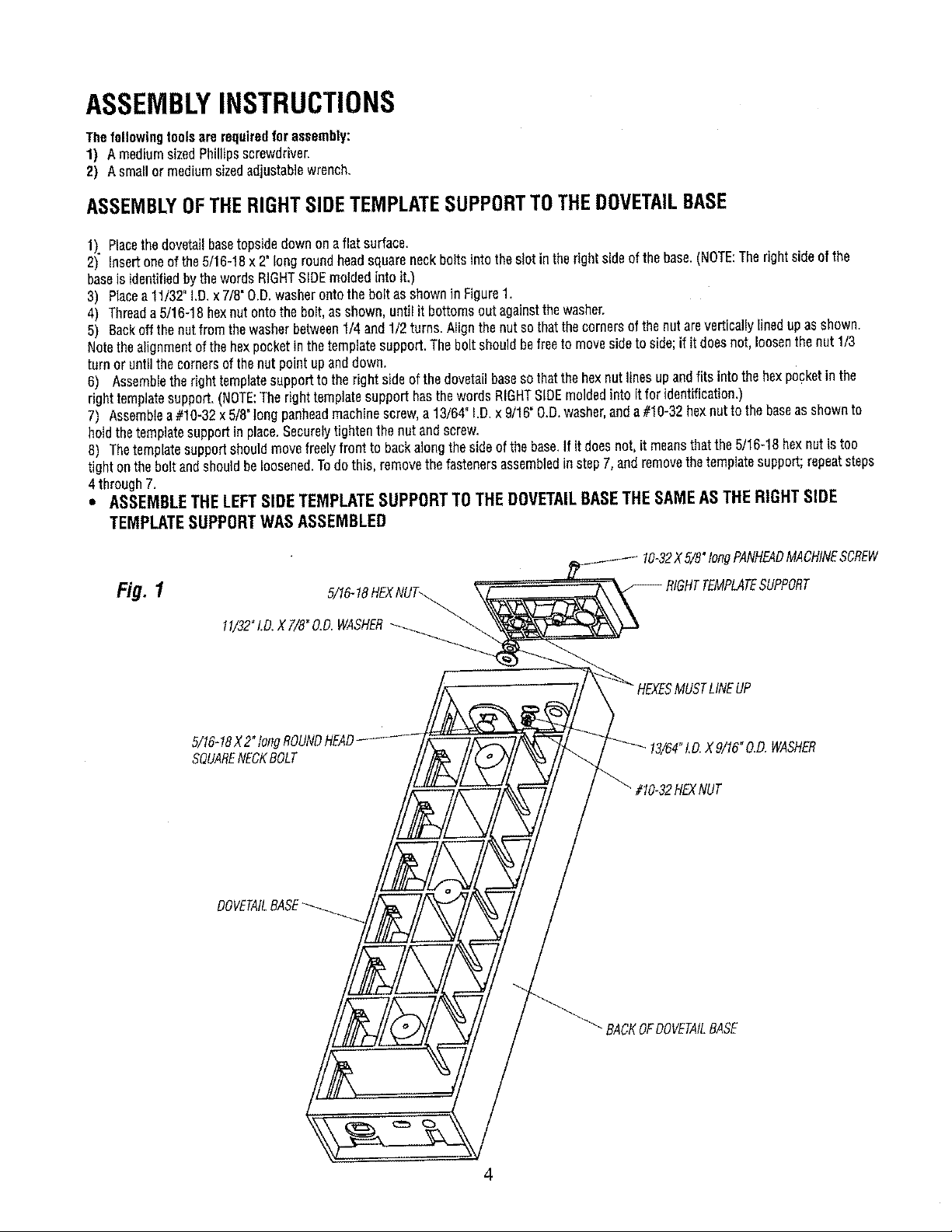
ASSEMBLYOFTHERIGHTSIDETEMPLATESUPPORTTOTHEDOVETAILBASE
1). Placethedovetailbasetopsidedownonaflatsurface.
2) insertoneof the5/16-18x2"longroundheadsquareneckboltsintothes!otintherightsideofthebase.(NOTE:Therightsideof the
baseis identifiedbythewordsRIGHTSIDEmoldedintoit.)
3) Placea11/32"I.D_x 7/8"O.D.washerontothe boltasshownin Figure1,
4) Threada5/16-18hexnutontothebolt,asshown,untilit bottomsoutagainstthe washer,
5) Backoffthenutfromthe washerbetween1/4 and1/2turns.NighthenutsothatthecornersofthenutareverticallYlineduPasshown.
Notethe alignmentofthe hexpocketinthetemplatesupport.Theboltshouldbefreeto movesidetoside;if it doesnot,loosenthenut1/3
turnor untilthe cornersofthenutpointupanddown.
8) Assembletherighttemplatesupportto therightside ofthedovetailbaseso thatthe hexoutlinesupandf ts intothehexpocketinthe
righttemplatesupport,(NOTE:TherighttemplatesupporthasthewordsRIGHTSIDEmoldedintoitfor identification.)
7) Assemblea#10-32x5/8°tongpanheadmachinescrew,a 13/64"!.D.x 9/16"O.D.washer,anda#10"32hexnutt° thebaseassh°wnt°
holdthetemplatesupportin place.Securelytightenthenut andscrew_
8) Thetemplatesupportshouldmovefreelyfrontto backalongthe sideofthe base,If it doesnot,it meansthatthe5/16-18hexnutis too
tight ontheboltandshouldbeloosened.Todothis, removethefastenersassembledinstepT,andremovethetemplatesupport;repeatsteps
4 through7.
• ASSEMBLE THE LEFT SIDE TEMPLATE SUPPORT TO THE DOVETAIL BASETHE SAME AS THE RIGHT SIDE
TEMPLATE SUPPORT WAS ASSEMBLED
Fig. 1
11/32"LO.XT/8"O.D.WASHER
5/16-18X2"tongROUNDHEAD
SQUARENECKBOLT
DOVETAILBASE
"/8"longPANHEADMACHINESCREW
MUSTLINEUP
_.D.WASHER
?HEXNUT
_ BACKOFDOVETAILBASE
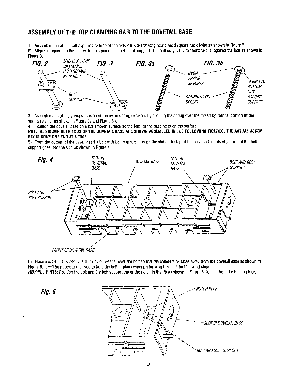
ASSEMBLYOFTHETOPCLAMPINGBARTOTHEDOVETAILBASE
1) Assembleoneoftheboltsupportsto bothofthe 5/16-18X3-1/2"longroundheadsquareneckboltsasshowninFigure2.
2) Alignthesquareonthe boltwiththesquareholeinthe boltsupport.Theboltsupportisto =bottom-out"againstthebolt asshownin
Figure3.
FIG.2 5/16-18X3-1/2"FIG.3
longROUND
HEADSQUARE _-x
FIG. 3a
,o,,
3) Assembleoneofthespringsto eachof thenylonspringretainersbypushingthespringovertheraisedcylindricalportionof the
springretaineras shownin Figure3aandFigure3b,
4) Positionthedovetailbaseonafiat smoothsurfacesothebackof thebaserestsonthesurface.
NOTE:ALTHOUGHBOTHENDSOFTHEDOVETAILBASEARESHOWNASSEMBLEDINTHEFOLLOWINGFIGURES,THEACTUALASSEM-
BLYIS DONEONEENDATATIME.
5) Fromthebottomofthe base,insertaboltwithboltsupportthroughtheslotin thetop of thebasesothe raisedportionofthe bolt
supportgoesinto theslot,asshowninFigure4,
Fig, 4 SLOTIN SLOTIN
BOLTAND
BOLTSUPPORT
FRONTOFDOVETAILBASE
6) Placea5/16"I.D.X 7/8"O.D.thick nylonwasheroverthe boltsothatthecountersinkfacesawayfromthedovetailbaseasshownin
Figure6. It will benecessaryfor youto holdthebolt in placewhenperformingthis andthefollowingsteps.
HELPFULHINTS:Positionthe boltandtheboltsupportunderthenotchin theribas shownin Figure5,to helpholdtheboltin place,
Fig. 5 _ NOTCHINRIB
DOVETAIL DOVETAILEASE DOVETAIL BOLTANDBOLT
EASE / BASE
SLOTINDOVETAILBASE
BOLTANDBOLTSUPPORT
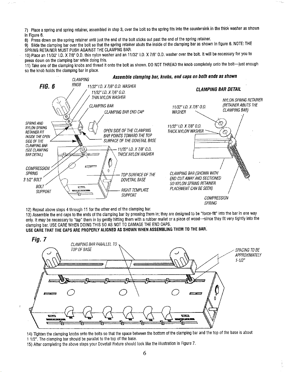
7) Placeaspringandspringretainer,assembledinstep3, overtheboltsothespringfitsintothecountersinkinthethickwasherasshown
InFigure6.
8) Pressdownonthespringretaineruntiljusttheendofthebolt sticksoutpasttheendofthe springretainer.
9) Slidetheclampingbaroverthebolt sothatthespringretainerabutstheinsideoftheclampingbarasshownin figure6.NOTE:THE
SPRINGRETAINERMUSTPUSHAGAINSTTHECLAMPNGBAR.
10)Placean11/32"I.D.X7/8"O.D.thin nylonwasherandan 11/3Z I.D.X7/8"O.D.washeroverthe bolt.It will benecessaryfor youto
pressdownonthe dampingbarwhiledoingthis.
11)Takeoneoftheclampingknobsandthreaditontothe boltasshown.DONOTTHREADtheknobcompletelyontothebolt--just enough
sothe knobholdsthe clampingbarinplace.
CLAMPING
FIG. 6 KNOB
SPRINGAND
NYLONSPRING
RETAINERFIT
INSIDETHEOPEN
SIDEOFTHE
CLAMPINGBAR
(SEECLAMPING
BARDETAIL)
SPRING
31/2"BOLT
BOLl
SUPPORT
12)Repeatabovesteps4through11for theotherendof theclampingbar.
13)Assembletheendcapstotheendsoftheclampingbarby pressingthemin; theyaredesignedto be"force-fit"intothebarin oneway
only.It maybenecessaryto "tap"themin bygentlyhittingthemwitha rubbermatletora pieceofwood--sincetheyfit verytightlyintothe
clampingbar,USECAREWHEN DOINGTHISSOAS NOT TO DAMAGE THEEND CAPS,
USECARETHATTHECAPSAREPROPERLYALIGNEDAS SHOWN WHEN ASSEMBLINGTHEM TO THEBAR.
tf/32"LD.X 7/B"O.D.WASHER
11/32"LD.X T/8"O.D.
THINNYLONWASHER
CLAMPINGBAR
\
Assembleclampingbar,knobs,endcaps on bothends asshown
CLAMPINGBARDETAIL
11/32"LD.X7/8"O.D. (RETAINERABUTSTHE
CLAMPINGBARENDCAP
WASHER LAMPING SAR)
OPENSIDEOFTHECLAMPING
BARPOINTSTOWARDTHETOP
SURFACEOFTHEDOVETAILBASE
11/32"LD.X 7/8"O,D.
t THICKNYLONWASHER
CLAMPINGBAR(SHOWNWITH /
DOVETAILBASE
/ TOPSURFACEOFTHE
-- RIGHTTEMPLATE
SUPPORT
ENDCUTAWAYANDSECT!ONED /
SONYLONSPRINGRETAINER /
PLACEMENTCANBESEEN) /
COMPRESSION
SPRING
NYLONSPRINGRETAINER
/
fig.7
CLAMPINGBARPARALLELTO
TOPOFBASE
J SPACINGTOBE
APPROXIMATELY
1-1/2"
0 0 0
14)Tightentheclampingknobsontothe boltssothatthespacebetweenthebottomoftheclampingbarandthetop of thebaseisabout
1 1/2".Theciampingbarshouldbeparallettothe topofthe base.
15)AftercompletingtheabovestepsyourDovetailFixtureshouldlookliketheillustrationin Figure7.
6
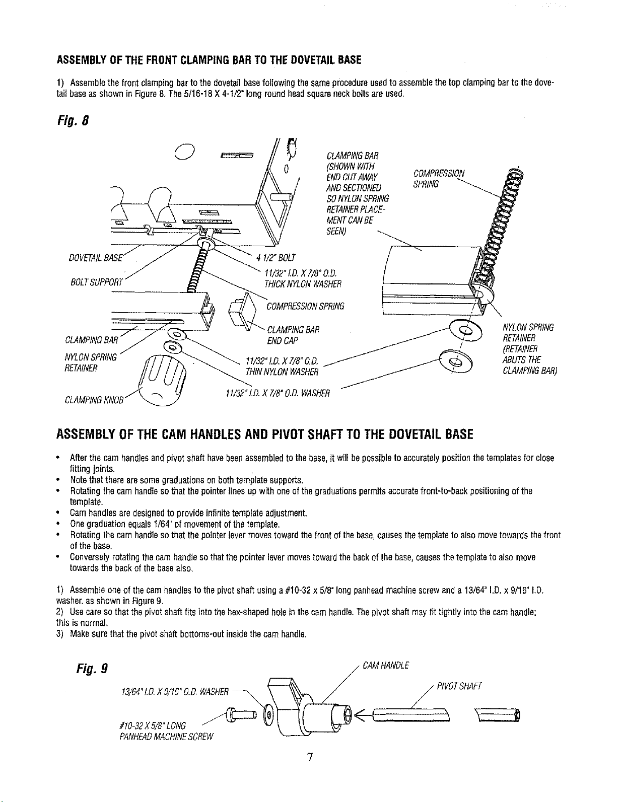
ASSEMBLYOFTHEFRONTCLAMPINGBARTOTHEDOVETAILBASE
1) Assemblethefront clampingbarto the dovetailbasefollowingthesameprocedureusedto assemblethetop clampingbartothedove-
tail baseasshownin Figure8.The5/16-18X4-1/2"longroundheadsquareneckboltsareused,
Fig. 8
CLAMPINGBAR
(SHOWNWITH
ENDCUTAWAY
ANDSECTIONED
SONYLONSPRING
RETAINERPLACE-
MENTCANBE
SEEN)
COMPRESSION
SPRING
BOLT
0
4 I/2" BOLT / ""
11/32"1.D.X7/8"O.D,
THICKNYLONWASHER
COMPRESSIONSPRING
CLAMPINGBAR
ENDCAP
1!/32"LD.X7/B"O.D,
RETAINER THINNYLONWASHER
11/32"I.D.X 7/8"O.D.WASHER
NYLONSPRING
RETAINER
(RETAINER
ABUTSTHE
CLAMPINGBAR)
ASSEMBLYOFTHECAMHANDLESAND PIVOTSHAFTTOTHEDOVETAILBASE
Afterthecamhandlesandpivotshafthavebeenassembledto thebase,it willbepossibleto accuratelypositionthetemplatesfor close
fittingjoints,
Notethattherearesomegraduationsonbothtemplatesupports.
• Rotatingthe camhandlesothat thepointerlinesupwithoneofthegraduationspermitsaccuratefront-to-backpositioningofthe
template.
• Camhandlesaredesignedto provideinfinitetemplateadjustment.
Onegraduationequals1/64"of movementof thetemplate.
• Rotatingthe camhandlesothat thepointerlevermovestowardthefrontof thebase.causesthetemplateto alsomovetowardsthefront
ofthe base.
• Converselyrotatingthecamhandlesothatthepointerlevermovestowardthebackofthe base,causesthetemplateto alsomove
towardsthebackofthe basealso.
1) Assembleoneofthe camhandlestothepivotshaftusinga #10-32x 5/8"longpanheadmachinescrewanda 13/64"I.D.x9/16"LD.
washer,asshownin Figure9,
2) Usecareso thatthe pivotshaftfitsintothehex-shapedholein thecamhandle.Thepivotshaftmayfit tightlyintothe camhandle;
this isnormal.
3) Makesurethatthepivotshaftbottoms*outinsidethecamhandle.
Fig. 9
/ CAMHANDLE
13/64"t.D.X9/16°0.O,WASHER--_,,,,_ _ PIVOTSHAFT
7
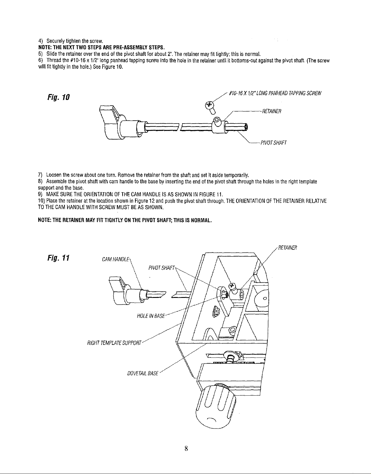
4) Securelytightenthescrew,
NOTE:THENEXTTWOSTEPSAREPRE-ASSEMBLYSTEPS.
5) Sgdetheretainerovertheendof thepivotshaftfor about2".Theretainermayfit tightly;thisis normal
6) Threadthe#1_`16x1/2"_ngpanheadtappingscrewint_theh_eintheretainerunti_itbott_ms-_tagain_tthepiv_tsha_.(Thescrew
willfit tightlyinthehole.)SeeFigure10.
Fig. 10
_ #!0-16X 1/2"LONGPANHEADTAPPINGSCREW
7) Loosenthescrewaboutoneturn.Removetheretainerfromtheshaftandsetit asidetemporarily.
8) Assemblethepivotshaftwith camhandleto the basebyinsertingtheendofthepivotshaftthroughthe holestntherighttemplate
supportandthebase.
9) MAKESURETHEORIENTATIONOFTHECAMHANDLEISASSHOWNINFIGURE11.
10)PlacetheretaineratthelocationshowninFigure12endpushthepivotshaftthrough.THEORIENTATIONOFTHERETAINERRELAT]VE
TOTHECAMHANDLEWITHSCREWMUSTBEASSHOWN.
NOTE:THERETAINERMAYFITTIGHTLYONTHEPIVOTSHAFT;THISISNORMAL.
Fig. 11
DOVETAILBASE
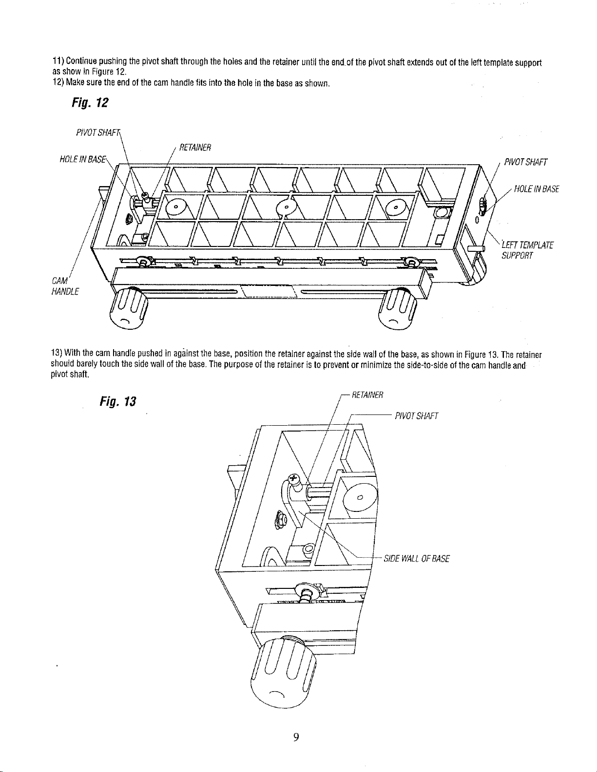
11)Continuepushingthepivotshaftthroughtheholesandtheretaineruntilthe endofthepivotshaftextendsout ofthelefttemplatesupport
asshowin Figure12.
12)Makesuretheendof thecamhandlefits intothe holein thebaseasshown,
Fig. 12
PIVOT,
HOLEINBASE,
CAM
HANDLE _"
13)Withthecamhandlepushedin againstthebase,positionthe retaineragainstthesidewallofthebase,asshownin Figure13.Theretainer
shouldbarelytouchthesidewall ofthe base.Thepurposeof the retaineristopreventor minimizetheside-to-sideofthecamhandleand
pivotshaft.
PtVOTSHAFT
SUPPORT
Fig. 13
RVOTSHAFT
-SIDEWALLOFBASE
9
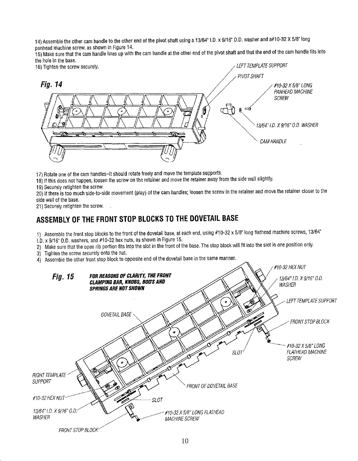
14)Assembletheothercamhandleto theotherendofthepivotshaftusinga13/64"I,D.x 9/16"O.D,washeranda#10-32X 5/8"long
penheadmachinescrew,asshownin Figure14.
15)Makesurethatthecamhandlelinesupwiththecamhandleattheotherendofthe pivotshaftandthattheendofthe camhandlefitsinto
theholein thebase.
16)Tightenthe screwsecurely, LEFTTEMPLATESUPPORT
Fig. 14
17)Rotateoneofthecamhandtes-ltshoutdrotatefreelyand movethetemplatesupports,
18)Ifthis doesnothappen,loosenthescrewontheretainerandmovetheretainerawayfrom thesidewallslightly,
19)Securelyretightenthescrew.
20)If thereistoomuchside-to-sidemovement(play)ofthecamhandles;loosenthescrewin theretainerandmovetheretainerc/osertothe
sidewaltof thebase.
21)Securelyretightenthescrew,
/_ #10-32X5/8"LONG
PANHEADMACHINE
SCREW
_" DAMHANDLE
ASSEMBLYOFTHEFRONTSTOPBLOCKSTOTHEDOVETAILBASE
1) Aseemblethefrontstopblockstothefront of thedovetailbase,ateachend,using#10-32x 5/8"longflatheadmachinescrews,13/64_
I.D.x 9/16"O.D.washers,and#!0-32 hexnuts,asshownin Figure15.
2) Makesurethattheopenrib portionfits intothe slotin the frontof thebase.Thestopblockwglfit intothe slotin onepositiononly,
3) Tightenthescrewsecurelyontothenut.
4) Assembletheotherfrontstopblocktooppositeendo1the dovetagbaseinthesamemanner.
Fig. 15
SUPPORT
#10-32HEX
13/64_LD.X9/16°O.D/
WASHER J
FRONTSTOPBLOCI_
FORREASONSOFCLARITY,THEFRONT
CLAMPINGBAR,KNOBS,BOLTSAND
SPRINGSARENOTSHOWN
DOVETAILBASE\
_ FRONTOFDOVETAtLBASE
5/8"LONGFLATHEAD
MACHINESCREW
10
SLOT_
WASHER
#10_32XB/8OLONG
FLATHEADMACHINE
SCREW
ASSEMBLYOFTHETOPSTOPBLOCKSTOTHEDOVETAILBASE
• Thetopstopblocksareassembledtothetopof thedovetailbaseinoneoftwowaysdependinguponwhichstyleofdovetailjoint is
to becut:
a) HALF-BLINDFLUSHJOINTS--The"A" onthestopblockfacestowardthe "middleofthebase".
b) HALF-BUNDRABBETJOINTS_The"B"onthestopblockfacestowardthe"middleofthe base".
c) THROUGHJOINTS--The"A" onthestopblockfacestowardthe"middleofthebase".
• Sincetheflushjoint isthemorecommonlyusedjoint,thefollowinginstructionsapplytotheassemblyofthestopblocksforthis
stylejoint.
1) Positionthedovetailfixturerightsideuponaflat surface.
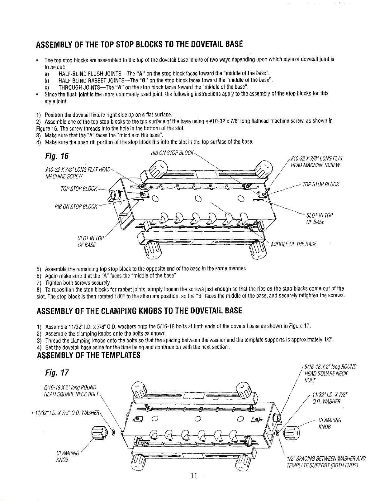
2) Assembleoneofthetopstopblockstothetopsurfaceof thebaseusinga#10-32x 7/8"longflatheadmachinescrew,as shownin
Figure16.Thescrewthreadsintotheholeinthe bottomofthesIot.
3) Makesurethatthe "A" facesthe "middleofthebase".
4) Makesuretheopenribportionofthestopblockfits intotheslot in thetop surfaceofthebase.
Fig. 16 RfBONSTOPBLOCK_
#10_32X 7/8_LONG \
MACHINESCREW
SLOTINTOP/
OFBASE
5) Assembletheremainingtopstopblocktotheoppositeendofthe baseinthesamemanner.
6) Againmakesurethatthe"A"facesthe"middleofthebase"
7) Tightenbothscrewssecurely.
8) Torepositionthestopblocksforrabbetjoints,simplyloosenthescrewsjustenoughsothatthe ribsonthestopblockscomeoutof the
slot,Thestopblockisthenrotated180° to thealternateposition,sothe"B"facesthe middleofthebase,andsecurelyretightenthescrews.
MIDDLEOFTHEBASE
#t0-32X7/8"L'ONGFLAT
HEADMACHINESCREW
TOPSTOPBLOCK
SLOTIN TOP
OFBASE
ASSEMBLYOFTHECLAMPINGKNOBSTOTHEDOVETAILBASE
1) Assemb_e1_/32"_D.x 7/8"____was_ers_ntot_e_/1_-18b_itsat b_thends_ft_ed__etai__aseassh__nin Figure17_
2) Assembletheclampingknobsontothe boItsasshown.
3) Threadtheclampingknobsontotheboltsso thatthespacingbetweenthewasherandthetemplatesupportsisapproximately1/2".
4) Setthe dovetailbaseasideforthetimebeingandcontinueon withthenextsection.
ASSEMBLYOFTHETEMPLATES
/ 5/16-18X2"longROUND
Fig. 17 / HEADSQUARENECK
BOLT
5/t6-t8X2°tongROUND
HEADSQUARENECKBOLT\
CLAMPING/
KNOB
\
!/2"SPACING8ETWEFNWASHERAND
TEMPLATESUPPORT(BOTHENOS)
11
11/32"I.D.XT/8"
// O.D,WASHER
KNOB
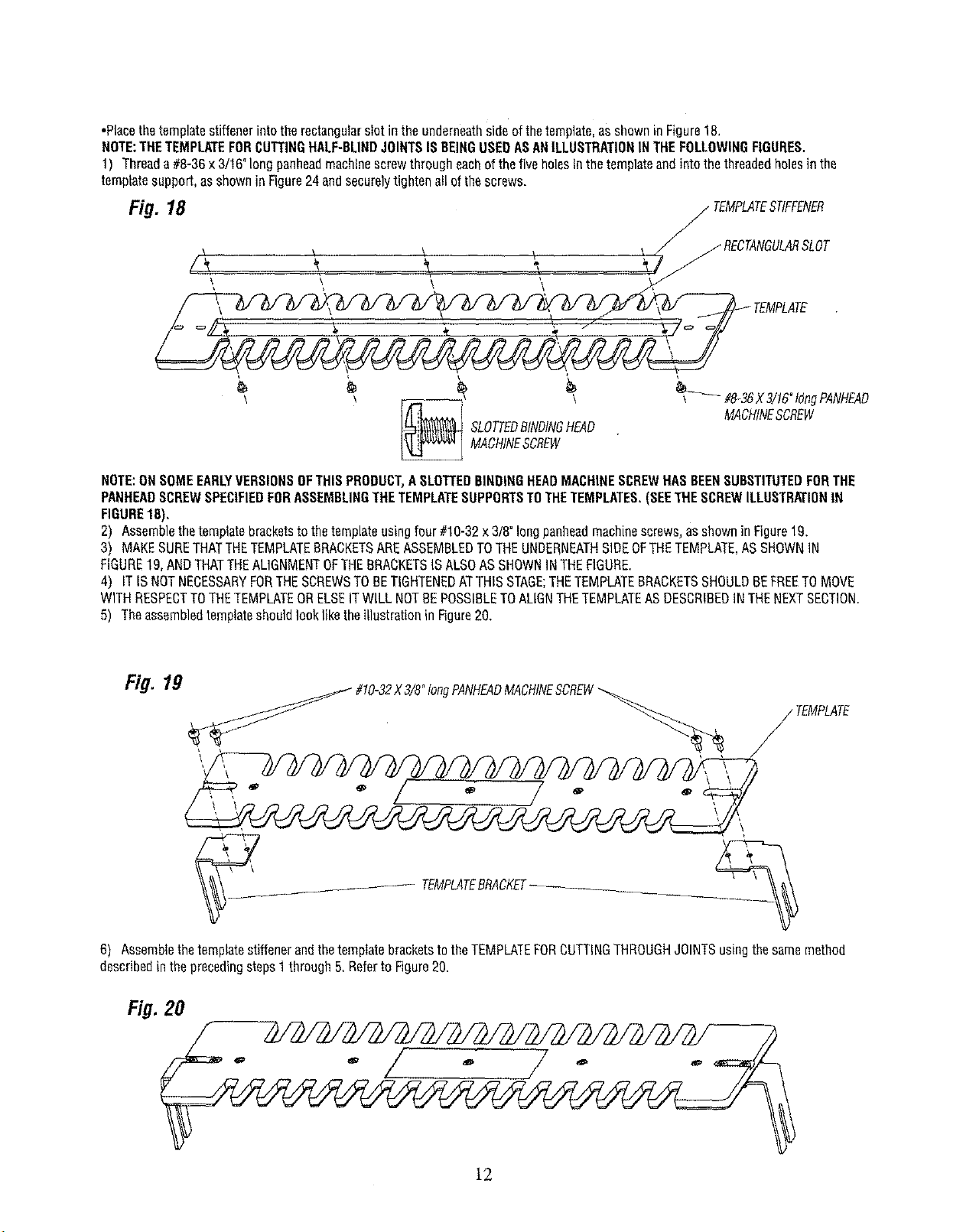
•Placethetemplatestiffenerintotherectangularslotintheunderneathsideofthetemplate,asshowninFigure18.
NOTE:THETEMPLATEFORCUTTINGHALF-BLINDJOINTSISBEINGUSEDASANILLUSTRATIONINTHEFOLLOWIHGFIGURES.
1) Threada #8-36x3/16"longpanheadmachinescrewthrougheachofthe fiveholesinthetemplateandintothethreadedholesinthe
templatesupport,asshowninFigure24andsecurelytightenallofthescrews.
Fig. 18 _ TEMPLATESTIFFENER
\ _ _ _ J jRECTANGULARSLOT
TEMPLATE
_ _ MACHINESCREwSLOTTEDBINDINGHEAD_ _ MA#&3gX3!!6"t°ngPANHEADcHINESCREW
NOTE:ONSOMEEARLYVERSIONSOFTHISPRODUCT,ASLOTTEDBINDINGHEADMACHINESCREWHASBEENSUBSTITUTEDFORTHE
PANHEADSCREWSPECIFIEDFORASSEMBLINGTHETEMPLATESUPPORTSTOTHETEMPLATES.(SEETHESCREWILLUSTRATIONIN
FIGURE18),
2) Assemblethetemplatebracketstothetemplateusingfour#10-32x3/8°longpanheadmachinescrews_asshownin Figure19.
3) MAKESURETHATTHETEMPLATEBRACKETSAREASSEMBLEDTOTHEUNDERNEATHSIDEOFTHETEMPLATE,ASSHOWNIN
FIGURE19,ANDTHATTHEAL]GNMENTOFTHEBRACKETSISALSOASSHOWNINTHEFIGURE.
4) ITIS NOTNECESSARYFORTHESCREWSTOBETIGHTENEDATTHISSTAGE;THETEMPLATEBRACKETSSHOULDBEFREETOMOVE
WITHRESPECTTOTHETEMPLATEORELSEITWILLNOTBEPOSSIBLETOALIGNTHETEMPLATEASDESCRIBEDINTHENEXTSECTION.
5) TheassembledtemplateshouldlookliketheillustrationinFigure20.
Fig. 19
#10-32X3/8"tongPANHEADMACHINESCREW
TEMPLATE
'\
_- TEMPLATEBRACKET....
6) AssemblethetemplatestiffenerandthetemplatebracketstotheTEMPLATEFORCUTTINGTHROUGHJOINTSusingthesamemethod
describedintheprecedingsteps1through5,Referto Figure20.
Fig. 20
lg
ALIGNMENTOFTHETEMPLATES
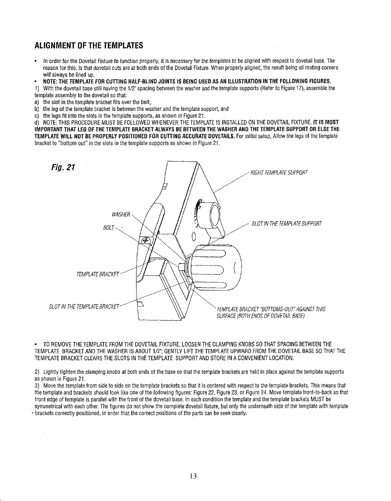
Inorderfor the DovetailFixturetofunctionproperly,it isnecessaryfor thetemplatesto bealignedwithrespectto dovetailbase.The
reasonforthis, isthatdovetailcutsareatboth endsoftheDovetailFixture.Whenproperlyaligned,theresultbeingall matingcorners
willalwaysbelinedup.
NOTE:THETEMPLATEFORCUTTINGHALF-BLINDJOINTSISBEINGUSEDASANILLUSTRATIONINTHEFOLLOWINGFIGURES,
1) Withthedovetailbasesti!lhavingthe1/2"spacingbetweenthewasherandthetemplatesupports(Referto Figure17),assemblethe
templateassemblytothedovetailsothat:
a) theslotin thetemplatebracketfitsoverthebolt,
b) thelegofthe templatebracketis betweenthe washerandthetemplatesupport,and
c) thelegsfit intotheslotsinthetemplatesupports,asshownin Figure21.
d) NOTE:THISPROCEDUREMUSTBEFOLLOWEDWHENEVERTHETEMPLATEISINSTALLEDONTHEDOVETAILFIXTURE.ITISMOST
IMPORTANTTHATLEGOFTHETEMPLATEBRACKETALWAYSBEBETWEENTHEWASHERANDTHETEMPLATESUPPORTORELSETHE
TEMPLATEWILLNOTBEPROPERLYPOSITIONEDFORCUTTINGACCURATEDOVETAILS.Forinitialsetup,Allowthelegsofthetemplate
bracketto "bottomout" intheslotsinthe tempiatesupportsasshownin Figure21.
Fig. 21
_ RtGHTTEMPLATESUPPORT
WASHER
BOLT_
j SLOTINTHETEMPLATESUPPORT
0
TEMPLATEBRACKET
SLOTIN THETEMPLATEBRACKET
TOREMOVETHETEMPLATEFROMTHEDOVETAILFIXTURE,LOOSENTHECLAMPINGKNOBSSOTHATSPACINGBETWEENTHE
TEMPLATEBRACKETANDTHEWASHERISABOUT1/2";GENTLYLiFTTHETEMPLATEUPWARDFROMTHEDOVETAILBASESOTHATTHE
TEMPLATEBRACKETCLEARSTHESLOTSINTHETEMPLATESUPPORTANDSTOREINACONVENIENTLOCATION,
2) LightIytightentheclampingknobsatbothendsof thebasesothatthetemplatebracketsareheldin placeagainstthetemplatesupports
asshowninFigure21.
3) Movethetemplatefrom sideto sideonthetemplatebracketsso thatitiscenteredwithrespecttothe templatebrackets,Thismeansthat
thetemplateandbracketsshouldlookIikeoneofthefollowingfigures:Figure22,Figure23,or Figure24,Movetemplatefront-to-backsothat
front edgeoftemplateisparallelwith thefrontofthe dovetailbase.IneachconditionthetemplateandthetemplatebracketsMUSTbe
symmetricalwith eachother.Thefiguresdonot showthecompletedovetailfixture,butonlytheunderneathsideofthetemplatewithtemplate
bracketscorrectlypositioned,in orderthatthecorrectpositionsofthe partscanbeseenclearly.
"_TEMPLATEBRACKET"BOTTOMS-OUT"AGAINSTTHIS
SURFACE(BOTHENDSOFDOVETAILBASE)
]3
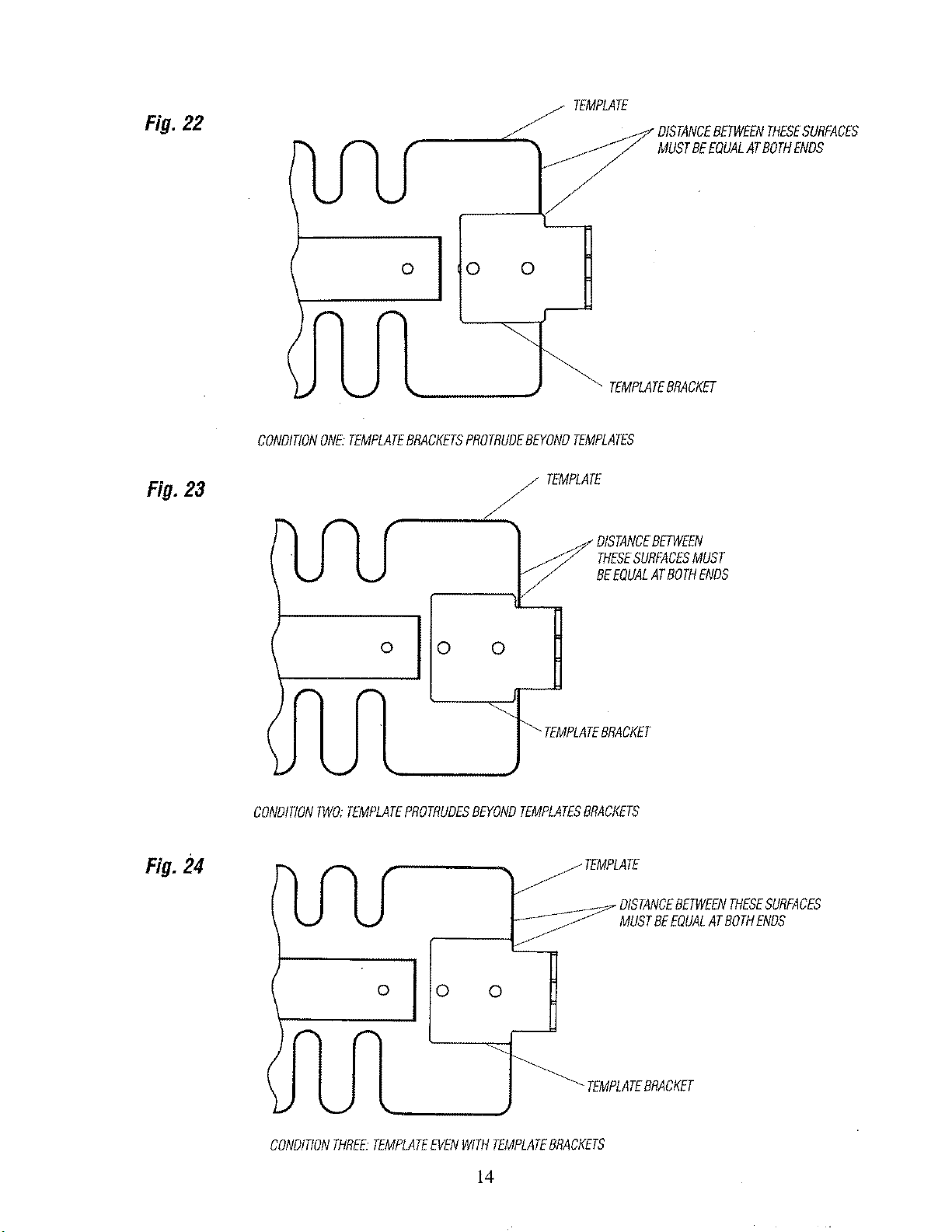
Fig. 22
TEMPLATE
_"DISTANCEBETWEENTHESESURFACES
MUSTBEEQUALATBOTHENDS
I
TEMPLATEBRACKET
CONDITIONONE."TEMPLATEBRACKETSPROTRUDEBEYONDTEMPLATES
Fig. 23
.24
j TEMPLATE
J
F
THESESURFACESMUST
BEEQUALATBOTHENDS
o
_0 0 TEMPLATEBRACKET
CONDITIONTWO;TEMPLATEPROTRUDESBEYONDTEMPLATESBRACKETS
MUSTBEEQUALATBOTHENDS
o 0
CONDITIONTHREE.TEMPLATEEVENWITHTEMPLATEBRACKETS
0
TEMPLATEBRACKET
14
4) Afterthetemplatebracketshavebeencorrectlypositionedonthetemplatesecurelytightenthefourscrewsholdingthetemptatebrackets
to thetemplate.
5) Removethetemplateassemblyfromthebaseandsetit asidefornow.
6) Aligntheothertemplateassemblyin thesamemanner,
ITSHOULDBENOTEDTHATYOUMAYFIND,THATAFTERMAKINGSOMESAMPLECUTS,SLIGHTADJUSTMENTSMAYBEREQUIRED.
HOWTOMAKETHESEADJUSTMENTSIS EXPLAINEDINTWOOFTHEFOLLOWINGSECTIONS:"MAKINGADJUSTMENTSFORHALFBLIND
JOINTS"or "MAKINGADJUSTMENTSFOROPEN(THROUGH)JOINTS".
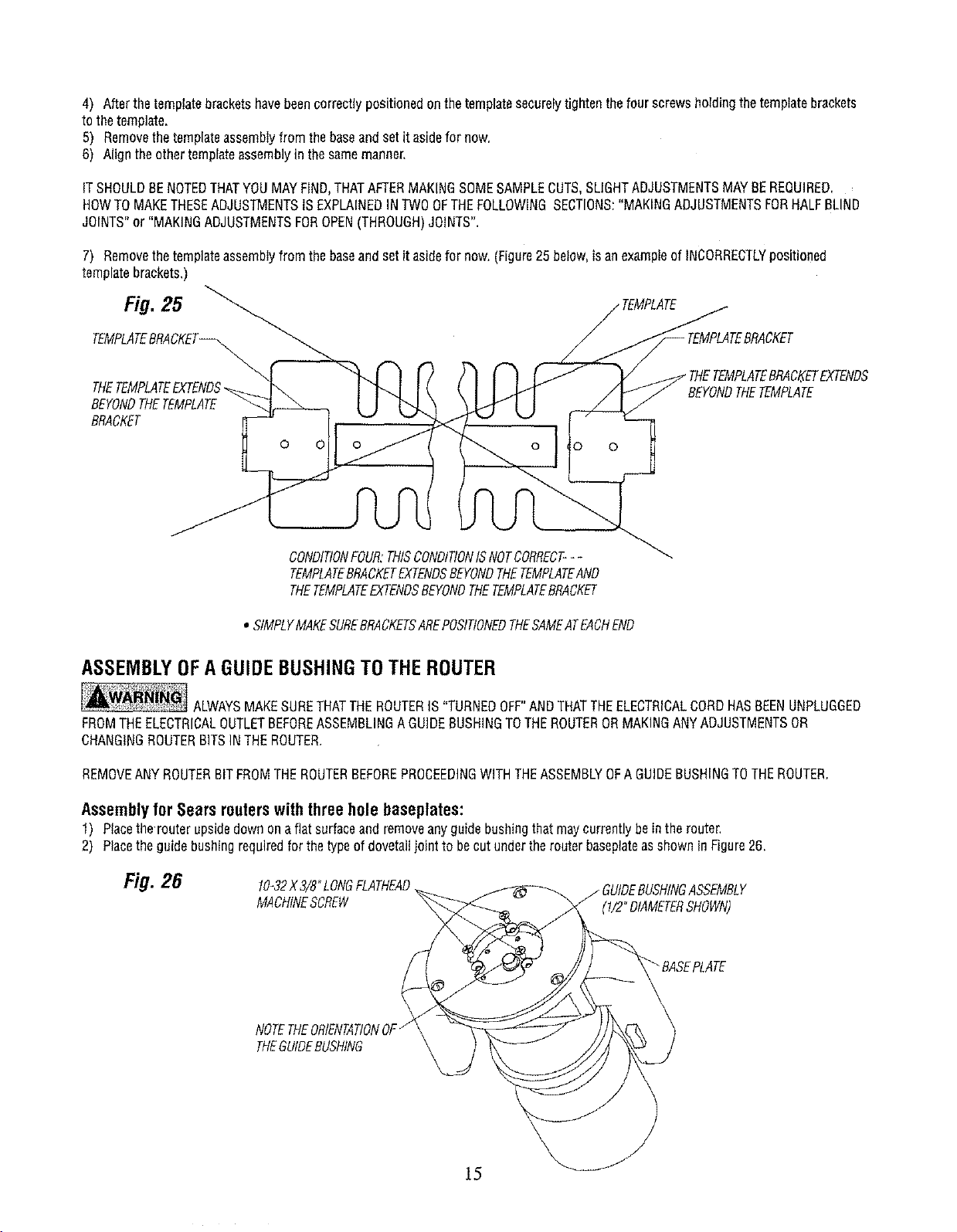
7) Removethetemplateassemblyfromthebaseandsetit asidefornow.(Figure25 below,isanexampleofINCORRECTLYpositioned
templatebrackets,)
CKET
THETEMPLATEBRACKETEXTENDS
tEMPLATE
BEYONDTHETEMPLATE
BRACKET
0
o
!o 0
CONDITIONFOUR:THISCONDITIONISNOTCORRECT---
TEMPLATEBRACKETEXTENDSBEYONDTHETEMPLATEAND
THETEMPLATEEXTENDSBEYONDTHETEMPLATEBRACKET
• StMPLYMAKESUREBRACKETSAREPOSITIONEDTHESAMEATEACHEND
ASSEMBLYOFA GUIDEBUSHINGTOTHEROUTER
ALWAYSMAKESURETHATTHEROUTERIS"TURNEDOFF"ANDTHATTHEELECTRICALCORDHASBEENUNPLUGGED
FROMTHEELECTRICALOUTLETBEFOREASSEMBLINGAGUIDEBUSHINGTOTHEROUTERORMAKINGANYADJUSTMENTSOR
CHANGINGROUTERBITSINTHEROUTER.
REMOVEANYROUTERBITFROMTHEROUTERBEFOREPROCEEDINGWITHTHEASSEMBLYOFA GUIDEBUSHINGTOTHEROUTER.
Assembly for Sears routers with three hole baseplates:
1) Placethe'routerupsidedawnonaflat surfaceandremoveanyguidebushingthatmaycurrentlybeinthe router,
2) Placetheguidebushingrequiredforthetypeof dovetagjointto becutundertherouterbaseplateasshownin Figure26.
Fig. 26
10-32X3/8°LONGFLATHEAD
MACHINESCREW
NOTETHEORIENTATIONOF"
THEGUIDEBUSHING
(1/2"DIAMETERSHOWN)
 Loading...