

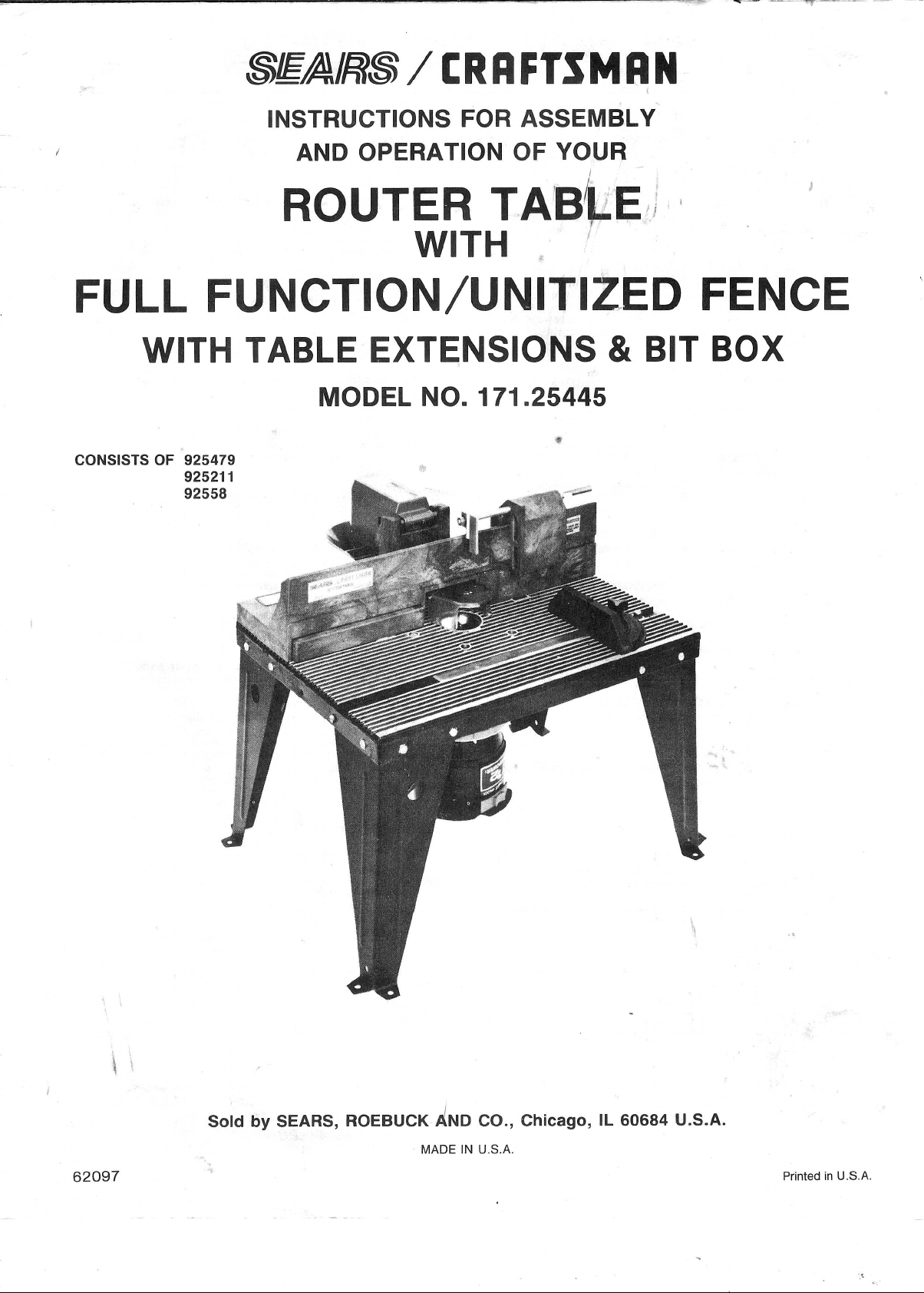
Page 1
Page 2
Page 3
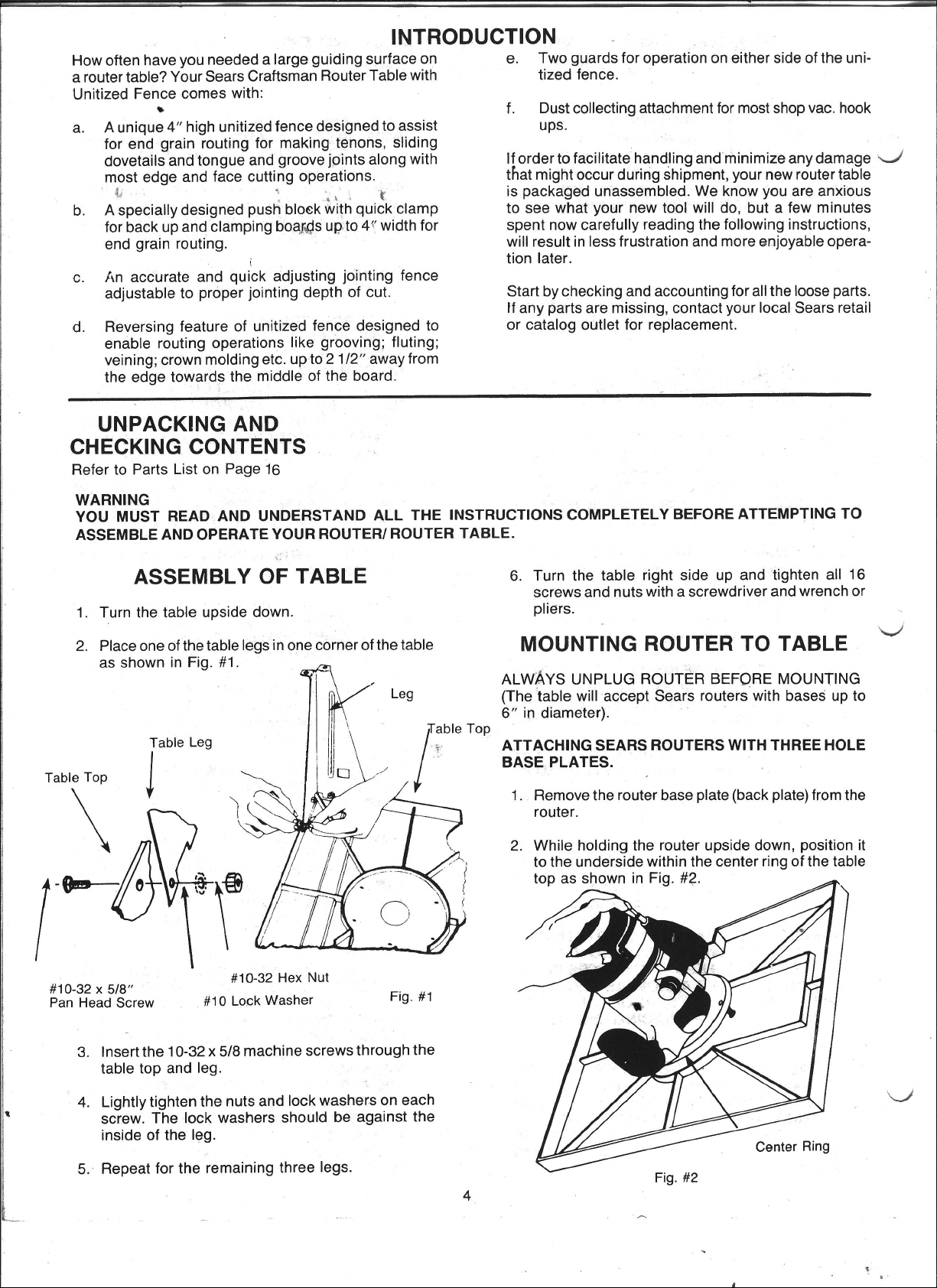
Page 4
Page 5
Page 6

Page 7

Page 8

Page 9

Page 10

4.
Raise or lower the router until top cutting edge
bit
is
aligned with
owner's
manual for adjusting your router properly) .•
line'S'.
(Refer to your router's
AFTER MAKING THIS ADJUSTMENT, SE SURE
ROUTER
ROUTER
ENED
BASE
5.
Remove the board from the fence.
IS
SECURELY TIGHTENED
SASE, THE SIT
IN
THE ROUTER CHUCK, AND ROUTER
IS
TIGHTLY SECURED TO TABLE TOP.
IS
SECURELY TIGHT-
IN
of
THE
described before. (MAKE
SURE ROUTER
UNPLUGGED WHEN MAKING ADJUSTMENTS).
3.
Check your adjustments by turning the router
and feeding a piece of scrap wood a few inches
beyond router bit. Then stop and turn router 'OFF'.
NOTE: Feed work
on
label on the frontside of unitized fence
(when facing
in
the direction of arrow shown
table front).
IS
'ON'
WARNING:
WHEN
ADJUSTING
HEIGHT
OF
ROUTER BIT FOR ANY DESIRED
CUT, MAKE
T AIN
THAT
THE
RETRACTABLE
SHOWN
SEE
THAT
FREELY
ITS NORMAL POSITION OVER
ABSOLUTELY
TOP OF BIT IS BELOW
INSIDE
SURFACE
GUARD
IN
FIG. #19. CHECK TO
GUARD
IN
AND OUT OF FENCE TO
RETRACTS
CER-
OF
AS
THE
(Retractable Guard not Shown
Clarity)
ROUTER TABLE HOLE. DO NOT
OPERATE ROUTER IF ANY PART
OF
THE
BIT
CONTACTS
THE
Small Knob
Jointing Fence
GUARD.
c----:;===~-
Inside Surface of Face of
Retractable
_G_u-:a:::rd==~~~~~~E~~~~~~=~JOinting
Fig. #19
"OTE:
The
procedure
described
Top of Bit
above
Fence
is
intended to provide a way of retracting and
holding the guard to have full access to the
router bit for making adjustments.
piece
to
be
routed could be substituted for
Work-
the scrap board for making adjustments.
4.
Loosen knob on jointing fence and move it out,
flush against the finished edge of scrap wood.
Retighten the knob.
lib:
==
on
~
________
Finished Edge Fig.
_____________________
See Fig. #20.
for.
#20
5. Repeat the test cut on the scrap wood.
6.
The router table
is
now ready for use.
NOTE: For best jointing results, take very shallow
cuts -
USING ROUTER
1/32"
or less.
TABLE FOR EDGE CUTTING WITH
NON-PILOTED BITS
~U~n~it~ized
Table Front
Fence
'--
USING RO'UTER
TABLE
AS JOINTER (FULL EDGE
CUTTING)
For maximum strength and accuracy, boards to
be
jointed together should be smooth and true. The edges
should be true to the workpiece surface. You can true
the edges on your router
1.
Check to see if face of jointing fence
the face of unitized fence.
on
jointing fence and push jointing fence inside the
cavity in unitized fence. Tighten knob
table using a straight bit.
is
flush with
If not, loosen small knob
on
jointing
fence.
NOTE: The jointing fence provides a continuous
support for the workpiece, as it is fed
beyond the router bit.
the gap created by the
by the router bit.
rial
2.
Adjust depth of cut (material you want to remove)
and router bit height
#18.
Tightly secure the fence and the router
as
It compensates for
removal of mate-
described before for Fig.
as
10
1.
Position the jointing fence such that its face
with the face of unitized fence. Tighten small knob
on jointing fence. See Fig. #21.
Large Knobs
Feed Workpiece
Direction of Arrow
Retractable Guard
Fig.
#21
is
flush
in
Table Front
Page 11

2. Adjust depth of cut (material you want to remove)
and router bit height
both
large knobs to lock fence on table. Tightly
secure the router. (MAKE
as
described before. Tighten
SURE ROUTER
IS
UNPLUGGED WHEN MAKING ADJUSTMENTS).
3.
Test cut a piece of scrap wood to make sure your
adjustments are satisfactory.
NOTE: Feed work in the direction of arrow shown
on
4.
The router table
label on frontside
(when facing
is
now ready for use.
table front).
of
unitized fence
NOTE: If you have purchased a MOLD MAKER
BIT SET (Sears Craftsman
~21255)
for
making moldings on your router table, set
the unitized fence
in
EDGE CUTTING
MODE for making the first cut on your
workpiece using Bit #25527.
See Fig. #22.
Unitized Fence in
Edge Cutting Mode
NOTE: If you have purchased RAIL AND STILE
CUTTERS
making cabinet door frames
table, MAKE
NESS
ness is more than
as shown
(Sears Craftsman
~21257)
on
your router
SURE THAT FRAME THICK-
is
not more than 3/4". If frame thick-
3/4", the top of the bit,
in
Fig. 'A' of Rail and Stile Cutters instructions, will interfere with retractable guard
on
your unitized fence. See Fig.
#24 and Fig. #19.
Door Frame Thickness
Must Not Be More
than
3/4"
USING ROUTER
Fig. #24
TABLE
FOR END CUTTING
When routing on ends of workpiece for making tenons,
sliding dovetails and tongue and groove joints, the workpiece must be made smooth with both edges and ends
made true to each other and its surfaces.
for
WITH PILOTED TYPE BITS
When bits with pilots are used to control the cutting
de):>th:
1.
Position the jointing fence
with non-piloted bits.
2. Move the unitized fence back only enough to permit the pilot to control the cutting depth.
ing the unitized fence as close to the pilot as
possible
vent chances of
injury.
Retractable Guard not Shown for
:::Iarity)
will serve
an
See Fig. #23.
Router Bit #25527
Fig. #22
in
the same manner as
Position-
as
a back-up, and will help pre-
accident, and possible personal
8~§fE~~~~~Unitized
NOTE: The push block and clamp plate assembly will
EXAMPLE: CUTTING TENONS
1. Make certain that jointing fence
tion with its face flush with that of unitized fence.
2.
Mount push block assembly on unitized fence as
shown before in Figs. #12a and #12b.
3.
Install proper table insert into the table top hole.
4. Mark
close to the end to be cut. Line 'A' for FULL
OF CUT (total
remove) and line
OF TENON. See
Workpiece Side
Against Face of
Fence
not accommodate workpiece wider than 4".
is
lines'
A' and
locked
'8'
on the edge of the workpiece
in
posi-
DEPTH
amount of material you want to
'8'
for FULL DESIRED HEIGHT
Fig. #25.
Wing Nut
Line
'B'
I
Fig. #23
Piloted Bit
Feed Workpiece in
Direction of Arrow
Table Front 11
Edge of Table Top Hole
Max. Width
4"
Page 12

WARNING: DO
3/8"
Max. Depth of Cut
NOT
SET
DEPTH
MORE
DEPTH OF CUT IS MORE THAN
3/8",
PIECE
WILL INTERFERE WITH PORTION
'P'
WILL
FENCE AND HENCE YOU
NOT BE ABLE TO SLIDE WORKPIECE ACROSS
THE CUT. SEE
THAN
THE EDGE
WHEN SLIDING ACROSS
OF GUARD. THE GUARD THEN
NOT
3/8"
'E'
RETRACT
THE BIT TO MAKE
FIG. #27.
Fig. #26
OF
CUT
(FIG. #26). IF
OF WORK-
INSIDE
WILL
1
~
Max. Depth of Cut
NOTE/
6.
Slide workpiece close to the bit and adjust unitized
fence and the router
outer most cutting edge of bit
'A' and top cutting edge
'B'. See Fig. #25. Tightly secure the fence and the
router
AND
7.
Slide push block and therefore workpiece back to
let guard swing out to its normal position
in Fig. #27.
8.
Turn router and shop vac 'ON'. While holding push
block
FENCE with both hands (Fig. #27) and FINGERS
AT SAFE DISTANCE ABOVE GUARD AND SPINNING BIT,
FULL DEPTH
STOP
ENOUGH BEYOND SPINNING BIT TO ALLOW
GUARD TO RETRACT OUT FULLY TO ITS NORMAL POSITION).
Tighten wing nut just enough to clamp
workpiece
ING
sliding motion of push block which
may
finished tenon surface when cut.
#29.
as
described before
HEIGHT OF CUT.
and GUIDING WORKPIECE AGAINST
feed workpiece across the bit to make
FEED
in
position. OVERTIGHTEN-
wing nut could cause binding
result
in
variations and/or steps
See Fig.
as
described before so that
is
aligned with line
of
bit
is
aligned with line
in
ADJUSTING DEPTH
as
OF CUT
UNTIL
IN
ONE PASS.
WORKPIECE
(DO
IS FAR
in
the
in
turn
in
the
shown
NOT
Portion 'P'
..
Direction of Feed
..
Fig. #27
5.
Position workpiece between clamp plate and push
block such that its side
of the unitized fence, the end to be cut
on the edge
with
lines 'A' and
workpiece
wing nut
clamp plate stays oriented on workpiece as shown
in
Fig. #25. (This will retract guard inside the fence
and provide access to the bit for making adjustments. MAKE
WHEN
PIECE
of
the table top hole and edge marked
'8'
in
this position by snugly tightening the
on
clamp rod while making sure that
SURE ROUTER
POSITIONING AND CLAMPING WORK-
AND MAKING ADJUSTMENTS).
is
held flush against face
is
facing the router bit. Clamp
IS
UNPLUGGED
is
resting
NOTE: Clamp
to check your adjustments before making
your finished cut.
9.
Turn router and shop vac 'OFF'. Unclamp workpiece, and slide push block back.
10. Position and clamp the opposite side of workpiece
in the same manner as described
sure the wing nut
piece
in
position and end to
edge of
#9.
11
. To cut ends of the tenon, position and clamp work-
piece
except edge of workpiece
against face
resting on edge of table top hole. See Fig. #28.
Repeat steps
table top hole). Repeat steps #7, #8, and
in
and test cut a piece of scrap wood
in
is
tight just enough to clamp work-
be
cut is resting
the same manner as
of
fence and end to be cut should
#7,
#8,
#9,
EdQe
Face of Unitized Fence
in
step
should
and #10.
of Workpiece Flush Against
Step
#5
be
held flush
#5
(make
on
the
above
be
12
Page 13

NOTE: When cutting tenons, always clamp work-
piece with end to be cut resting
on
edge
of table top hole. This will minimize steps
in
finished tenon surface (Fig. #29) due to
variations
in
the table top flatness.
Steps
Tenon
Fig. #29
in
Finished
Surface
DO
NOT CONNECT SHOP
SIDE
OF
FENCE.
THE
VAC.
WHEN USING BACK-
HOSE
WILL
HINDER
OPERATION.
For maximum accuracy, one edge of your workpiece
(edge sliding against the fence) must be true and
straight.
1.
Set up your fence
Remove
hex head b
b
O!~
Clll
large knobs and 1/4-20 x 1 3/4"
ts,
turn the unitized fence around and
attach it back to table with backside of fence
as
follows:
Ig.
facing the table front. See Fig. #30. (MAKE SURE
ROUTER IS UNPLUGGED
WHEN REMOVING
AND ATTACHING FENCE TO TABLE).
WARNING: ALWAYS CUT FULL DEPTH
ON
ALL 4 SIDES OF TENON IN ONE
PASS ACROSS
THE
SIDES
STEPS
TIONS
OR
ARE
ISHED TENON SURFACE,
THEM
PAPER
WITH WOOD CHISEL, SAND
OR
THE BIT. ONCE
ARE
CUT
OTHER
NOTICED
FILE, ETC.
AND IF
IMPERFEC-
ON FIN-
CLEAN
DO
NOT TRY
TO CLEAN THEM BY RE-SETTING
WORKPIECE ON ROUTER
AND FENCE.
WORKPIECE MAY
TABLE
INTERFERE WITH GUARD (SEE
FIG.
#27 ABOVE) WHICH
IN
TURN
WILL PREVENT IT FROM SLIDING
ACROSS
THE BIT.
OPERATION - ROUTING USING
BACKSIDE OF UNITIZED FENCE
USE BACKSIDE OF FENCE ONLY FOR ROUTING
OPERATIONS
SIDE OF WORKPIECE SUCH
ING; VEINING; CROWN MOLDING, ETC.
AWAY FROM EDGE ON THE UNDER-
AS
GROOVING; FLUT-
Table Front
#30
Fig.
2.
Raise guard and let it lean against the fence.
ALWAYS UNPLUG THE ROUTER BEFORE MAKING
ANY SETTING, ADJUSTMENTS, OR CHANGING
BITS.
WHEN ROUTING ALWAYS FEED AGAINST THE
gOTATION OFTHE CUTTER. FEED WORKPIECE
'
rHE
DIRECTION OF ARROW AS SHOWN ON LABEL
IN
ON THE SIDE OF FENCE BEING USED (when facing
the table front).
13
3.
Position the fenee behind the router bit for the
desired cutting depth (the distance of the cut from
in
the edge of the workpiece, as shown
Fig. #31).
Page 14

NOTE; When routing deep cuts (controlled by
router
bit)'
in
a workpiece, remove material in increments to prevent your router
from
overloading. Repeat operation with
several passes until the desired depth
is
achieved.
PROTRACTOR
Back Side of
Unitized
Fenc:e
Router Bit
Fig.
#31
4. Securely tighten both knobs and LOWER THE
GUARD
5.
Make the cut by sliding straight edge of workpiece
OVER THE BIT.
against the fence. Use a push stick as shown
Fig.
#32
. (For each successive cut, the fence would
need to be readjusted).
NOTE: Test cut a piece of scrap wood before mak-
ing your finish cut. Feed workpiece
direction of arrow shown
on
in
the
fence label
(Fig. #32).
in
Feed Workpiece
of Arrow Shown
the Direction
on
this Label
in
Your protractor will serve
port
is
needed for routing small workpieces or ends of
as
a handy
aid
when extra sup-
large workpieces. See Fig. #33.
Workpiece
Fig. #33
Miter Bar
Slot
NOTE: FOR ALL ROUTING OPERATIONS REQUIR-
ING USE OF MITER
THE FENCE, BE SURE
WITH MITER BAR SLOT
GAUGE ALONG WITH
TO
ALIGN FENCE
B~FORE
MAKING
ANY CUTS . SEE FIG. #17.
Back Side of
Unitized Fence
Fig. #32
Table
Front
14
Page 15

WARNING: FAILURE
USE OF THIS PRODUCT,
TABLE
OWNER'S
TO
MANUALS,
HEED
ALL
ALONG
ASSEMaL
WITH THOSE OPERATING
CAN RESULT IN SERIOUS
Y,
SAFETY,
AND OPERATI NG INSTRUCTIONS A
INSTRUCTIONS
BODilY
INJURY.
AND
WARNINGS
IN
ND
THE
WARNINGS
ROUTER
REGARDING THE
AND
THE ROUTER
~1E~/Rl~
/[RAFTSMAN
....cNERAL: The Router Table Extensions are used with
the 25443, 25444, 25475 and 25479, Router Table. The
extensions increase the length of the router table resulting in a larger work surface, allowing convenient additional support when routing long workpieces.
The extensions
CANNOT be used with the 25457 and
25473, Router Tables.
Eight screws, nuts, flat washers, and lockwashers are
packaged with this product which are necessary when
sembling the extensions to the
They are
Router
NOT used with the 25443, 25444, and 25479
Tab
les because those Router Tables come with a
sufficient quantity of fasteners
the
extensions to those Router Tables while the 25475
25475,
to
Router Table.
permit the assembly of
as-
does not.
NOTE:
proceed
EXTENSIONS
If
your Router Table has not been assembled yet,
to
the following section,
TO
THE ROUTER TABLE.
ASSEMBLING
If
your Router
THE
Table has already been assembled and used proceed as
follows:
a.
DISCONNECT THE POWER CORD TO THE ROUTER
FROM THE ELECTRICAL OUTLET.
b.
Remove any router bit that
c.
Lower the router so the router bit chucking nut is below
is
now
in
the router.
the top surface of the table .
, Remove all accessories, such
.l
and fences from table.
as
guards, miter gauge,
e. Place the table, top side down, on a flat surface and
disassemble the four legs from the table by removing
th~
screws, nuts, and washers that hold the legs in
place.
f.
Proceed to the following section.
ASSEMBLING
THE
EXTENSIONS
TO
THE ROUTER
TABLE.
Refer to the section in your Router Table Owner's Manual
concerning the assembly of the legs to the table .
ROUTER TABLE
EXTENSIONS
NO. 25211
2.
MAKE
SECUREL
3. Turn the table top side
extensions are even with
IN NO CASE
HIGHER
THEY
DURING ROUTING
CAN RESULT
4. If the extensions are
loosen the screws holding
tion them so they are even with or slightly lower than
the top
SCREWS AND
5. To double check, slide a flat piece of wood along the
top of the table in both directions. Make sure that the
end
edge
6. Continue with assembly
scribed
cessories and guards
WARNING:
PRESS
THEY
THAT
INJURY
SURE
ALL
Y:
TIGHTENED
SHOULD
THAN
MAY
of
THE
INTERFERE
IN
POSSIBLE
the table.
NUTS
of
the wood
of
the extension
in
the Owner'S
DO
moves
NOT
HEA VIL Y ON
MAY
BE
DAMAGED
CAN RESULT IN
DURING
ROUTING.
SCREWS
up
and check to see that the
or
slightly below the table top.
TOP
OF
WITH
CAUSING
AND NUTS ARE
THE
EXTENSIONS BE
THE TABLE OR ELSE
THE WORKPIECES
A CONDITION THAT
SERIOUS INJURY .
higher
than the top of the table,
the
extensions and reposi-
SECURELY
ONCE
AGAIN.
TIGHTEN
freely without contacting the
next
to the table.
of
the Router Table as de-
Manual
previously
PLACE
THE
POSSIBLE
or reassemble the ac-
removed.
HEAVY OBJECTS OR
EXTENSIONS OR ELSE
CAUSING
A CONDITION
SERIOUS BOOIL Y
ALL
1.
To assemble the Table Extensions to the Router Table,
place the table, top side down, on a smooth, flat surface, and position the Table Extensions relative to the
as
table
bling the legs to the table
making sure to tighten the screws marked
followed by the screws marked
shown. Now follow the procedure for assem-
in
the Owner's Manual,
"A"
"B".
The screws, that
normally just hold the legs to the table, will now also
hold the extensions on the table.
49L
-23
first
Sold
by
Chicago,
MADE
SEARS,
IL
IN
U.S.A.
60684
ROEBUCK
U.S.A.
AND
CO.,
3-89
Page 16

PARTS LIST FOR CRAFTSMAN ROUTER TABLE
MODEL
NO"
171"254790
36---10.<
II~
15--r
39
1
~
I
G3
~
___
-**
-34
17
21
2
~
Key
No.
"13
"14
"15
20
Part No. Description Quan.
1
31L-431 Router Table Top 1
31
L-429
2
·3
F29A·306· 14
"4
F29A·489-3 Hex HD Bolt 114-20 x 1
•
"5
F29A-242-2
31L-559 Miter Bar 1
6
31L-438 Pointer 1
7
F29A-264-8
"8
29L-183
9
29L-293 Protractor Head
10
11
31L-560 Knob
29L-202
12
29A-298-13 Flat Hd. Mach. Screw #10-32 x
29A-509-1
29A·306-15
16
29A-310-5 Carriage Boll
17
29L-646
18
29L-650 Guard
19
29L-647 Guard (Retractable)
29L-649
Table Leg
Flat Washer
Hex. Mach.
Pan Hd.
Grooved Pin
Plastic
1110
1/
1 0 Flat Washer 1
Unitized Fence 1
Jointing Fence 1
9/32
I.D. x 3/4 O.D.
3/4
Ig.
Screw Nut 1/10-32 17
Mach.
3/16
Insert
Lock Wasfler
1110-24
Screw #10-32 x
dia. x 5/8 type D
x 3/4 Ig. 1
5/16
3/8
16
Key
No.
Part No.
21
29L·648
4
3
2
1
1
1
1
5
3
1
1
22
29L·651
23
29L·652
"24
F·29A·246-1 2
25 29L-654
"26
F-29A-252-8
"27 F-29A-306-27
"28
29A-264-7
"29
F-29A-327-3
"30
F-29A-306-26
"31
F-29A-653
32 29L·660
29L-659
33
34 45A-289
45A-290
35
45A-297
36
37
29L-655
F29A-242-8
38
39
45A·292
Description
Push Block
Clamp Rod
Clamp Plate
Hex Hd. Bolt
Spring
Wing Nut
5/16
Pan Hd. Mach.
114" Lock Washer (Helical)
#8
Flat Washer
#8-10
114-20
1/4-20
Labea(Self Adhesive)
Label
Label
Vacuum Hose Reducer
Hex Nut
Label (Self Adhesive)
114-20 x
5/16-18
Flat Washer
Screw #10-32 x 5/8 Ig.
3/16
x 9/16
Lg.
Pan
Knob (large)
Knob (small)
(Self Adhesive)
(Self Adhesive)
114-28
1"
I.D. x
Hd.
Plasform Screw
Ig.
1I20.D.
Quan.
1
1
1
1
1
1
1
16
1
1
1
2
1
1
2
1
1
1
1
-"
"Hardware item - may
be
purchased locally.
16
 Loading...