

Craftsman 171.926501, 171.0970874 Owner's Manual
Owner's Manual
Manuel du propri_taire
Manual del Propietario
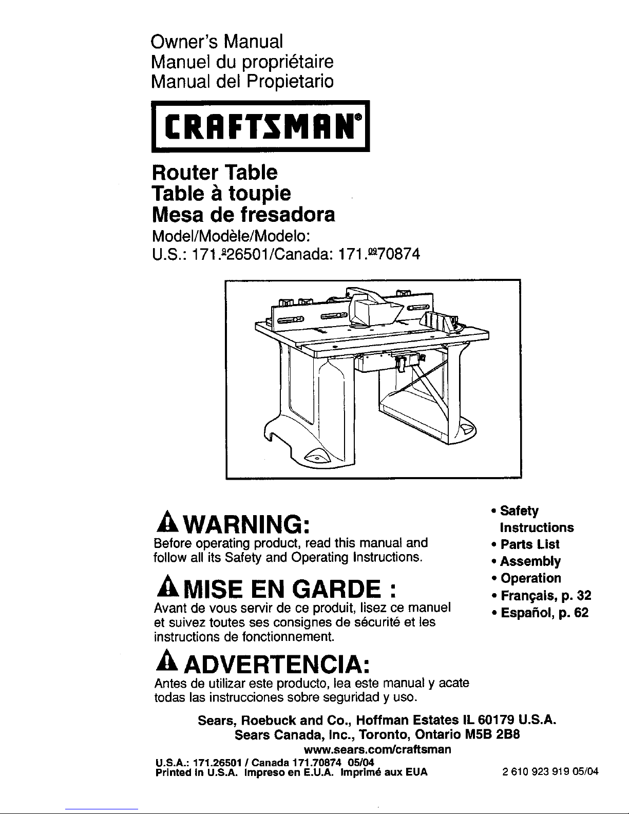
Router Table
Table & toupie
Mesa de fresadora
Model/Mod_le/Modelo:
U.S.: 171._26501/Canada: 171.°_70874
A WARNING:
Before operating product, read this manual and
follow all its Safety and Operating Instructions.
A MISE EN GARDE •
=
Avant de vous servir de ce produit, lisez ce manuel
et suivez toutes ses consignes de s_curit_ et les
instructions de fonctionnement.
ADVERTENCIA:
Antes de utilizar este producto, lea este manual y acate
todas las instrucciones sobre seguridad y uso.
• Safety
Instructions
• Parts List
• Assembly
• Operation
• Frangais, p. 32
• Espa_ol, p. 62
Sears, Roebuck and Co., Hoffman Estates IL 60179 U.S.A.
Sears Canada, Inc., Toronto, Ontario M5B 2B8
www.sears.com/craftsman
U.S.A.: 171.26501 /Canada 171.70874 05/04
Printed in U.S.A. Impreso en E.U.A, Imprimd aux EUA 2 610 923 919 05/04
_NE YEAR FULL WARRANTY -'_
If any part of this Craftsman Router Table is defective in material or workmanship within
one year from the date of purchase, return it to your nearest Sears Parts & Repair Center,
and it will be replaced free of charge.
WARRANTY SERVICE IS AVAILABLE BY CONTACTING SEARS SERVICE AT
1-800-4-MY-HOME. ®
This warranty gives you specific legal rights, and you may also have other rights which
vary from state to state.
Sears Roebuck and Co. Dept. 817 WA Hoffman Estates, IL 60179
J
General Safety Instructions for Power Tools ...
Additional Safety Instructions for Router Tables
Parts List .................................
Assembly ..............................
Operation ..............................
• • • • • • • • 12
• • • • • • • • 14
........ 8-11
..... 12-17
..... 18-30
J/k WARNING nRead and understand the tool manual and these instructions. Failure
I
to follow all instructions listed below may result inserious personal injury.
Work Area
Keep your work area clean and well lit.
Cluttered benches and dark areas invite
accidents.
Do not operate power tools in explosive
atmospheres, such as in the presence of
flammable liquids, gases, or dust. Power
tools create sparks which may ignite the dust
or fumes.
Keep bystanders, children, and visitors
away while operating a power tool.
Distractions can cause you to lose control.
Electrical Safety
Grounded tools must be plugged into an
outlet properly installed and grounded in
accordance with all codes and ordinances.
Never remove the grounding prong or
modify the plug in any way. Do not use
any adaptor plugs. Check with a qualified
electdcian if you are in doubt as to
whether the outlet is properly grounded.
If the tools should electrically malfunction
or break down, grounding provides a low
resistance path to carry electricity away from
the user. Improper grounding can shock, bum
or electrocute. Grounded tools are equipped
with three conductor cord and three prong
type plugs.
2
Before plugging in the tool, be certain
the outlet voltage supplied Is within the
voltage marked on the nameplate.
Do not use "AC only" rated tools with
a DC power supply.
Double Insulated tools are equipped with
a polarized plug (one blade is wider than
the other.) This plug will fit in a polarized
outlet only one way. If the plug does not fit
fully in the outlet, reverse the plug. If It still
does not fit, contact a qualified electrician
to install a polarized outlet. Do not change
the plug in any way. Double Insulation []
eliminates the need for the three wire
grounded power cord and grounded power
supply system.
Avoid body contact with grounded
surfaces such as pipes, radiators, ranges
and refrigerators. There is an increased risk
of electric shock if your body is grounded.
If operating the power tool in damp locations
is unavoidable, a Ground Fault Circuit
Interrupter must be used to supply the power
to your tool. Electrician's rubber gloves and
footwear will further enhance your
personal safety.
Don't expose power tools to rain or wet
conditions. Water entering a power tool will
increase the risk of electric shock.
Donotabusethecord.Neverusathecord
to carrythetoolsor pullthe plugfroman
outlet.Keepcord awayfromheat,oil,
sharpedgesor movingparts.Replace
damagedcordsimmediately.Damaged
cordsincreasetheriskofelectricshock.
Whenoperatingapowertooloutside,use
anoutdoorextensioncordmarked"W-A"
or "W." These cords are rated for outdoor
use and reduce the risk of alectric shock.
Refer to "Important Information about
Extension Cords".
Personal Safety
Stay alert, watch what you are doing and
use common sense when operating a
power tool. Do not use tool while tired or
under the influence of drugs, alcohol, or
medication. A moment of inattention while
operating power tools may result in serious
personal injury.
Keep guards in place. Maintain the guards in
working order and in proper adjustment and
alignment.
Avoid accidental starting. Be sure switch
is "OFF" before plugging in. Carrying tools
with your finger on the switch or plugging
in tools that have the switch "ON" invites
accidents.
Remove adjusting keys or wrenches
before turning the tool "ON". A wrench or a
key that is left attached to a rotating part of
the tool may result in personal injury.
Do not overreach. Keep proper footing
and balance at all times. Proper footing and
balance enables better control of the tool in
unexpected situations.
Use safety goggles (head protection).
Wear safety goggles (must comply with ANSI
Standard Z87.1 ) at all times. Wear non-slip
footwear and a hard hat, ifappropriate. Also,
use face or dust mask if cutting operation is
dusty, and ear protectors (plugs or muffs)
during extended periods of operation.
Tool Use and Care
Use clamps or other practical way to
secure and support the workpiece to a
stable platform. Holding the work by hand
or against your body is unstable and may lead
to loss of control.
Do not force tool. Use the correct tool for
your application. The correct tool will do the
job better and safer at the rate for which it is
designed.
Do not use tool if switch does not turn it
"ON" or "OFF". Any tool that cannot be
controlled with the switch is dangerous and
must be repaired.
Disconnect the plug from the power
source before making any adjustments,
changing accessories, or storing the tool.
Such preventive safety measures reduce the
risk of starting the toot accidentally.
Keep guards In place. Maintain the guards in
working order and in proper adjustment and
alignment.
Store idle tools out of reach of children
and other untrained persons. Tools are
dangerous in the hands of untrained users.
Never leave tools running unattended.
Turn the power OFF. DO NOT leave tool
until it comes to a complete stop.
Maintain tools with care. Keep cutting
tools sharp and clean. Properly maintained
tools, with sharp cutting edges, are less likely
to bind and are easier to control. Any
alteration or modification is a misuse
and may result in a dangerous condition.
Check for damaged guards or parts,
misalignment or binding of moving parts,
breakage of parts, and any other condition
that may affect the tool's operation. If
damaged, have the tool properly repaired
or replaced before using. Many accidents
are caused by poorly maintained tools.
Develop a periodic maintenance schedule
for your tool.
Use only accessories that are
recommended by the manufacturer
for your model. Accessories that may
be suitable for one tool may become
hazardous when used on another tool.
Service
Tool service must be performed only
by qualified repair personnel. Service or
maintenance performed by unqualified
personnel could result in a risk of injury.For
example: internal wires may be misplaced or
pinched, safety guard return springs may be
improperly mounted.
When servicing a tool, use only identical
replacement parts. Use of unauthorized
parts or failure to follow Maintenance
Instructions may create a risk of electric
shock or injury. Certain cleaning agents such
as gasoline, carbon tetrachloride, ammonia,
etc. may damage plastic parts.
3
Read and understand table and router
manual and accessory warnings. Failure to
follow all instructions and warnings may
result in serious personal injury.
Fully assemble and tighten all fasteners
required for this table and for mounting
the router to the plate. Do not use the
router table until all assembly and
installation steps have been completed.
Check the stand and the router to make
sure fasteners are still tight before each
use. A loose stand is unstable and may
shift in use.
Make certain the router is not plugged
into a power outlet when installing into
the table, removing from table, making
adjustments or changing accessories.
Router could accidentally start. Power tool
switches and controls need to be within your
reach in emergency situations.
Before operating, make sure the entire unit
(table with router installed) is placed on
and secured to a solid, flat, level surface
and will not tip. Use of auxiliary in-feed
and out-feed supports is necessary for
long or wide workpieces. Long workpieces
without adequate support can flip off the table
or cause the table to tip over.
Be certain router motor is fully and
securely clamped in the router base.
Periodically check the base fastener
clamping tightness. Router motor can
vibrate loose from the base during use and
fall from table.
Do not use the router table without the
overhead guard or auxiliary bit guard.
Remove all dust, chips, and any other
foreign particles that can affect its
function. Adjust the guard height so that
it clears the router bit and the workpiece.
The guard will aid in keeping hands from
unintended contact with rotating bit.
Never place your fingers near a spinning
bit or under the guard when router is
plugged in. Never hold the workpiece
on the out-feed side of bit. Pressing the
workpiece against the out-feed side of the
fence may cause material binding and
possible kickback, pulling hand back into bit,
Guide workpiece by the fence to maintain
control of workpiece. Do not place material
behveen router bit and fence while routing
the edge. This placement will cause the
material to become wedged, making kickback
possible.
Routers are intended for working with
wood, woodlike products and plastic
or laminates, not for cutting or shaping
metals. Be sure workpiece does not
contain nails, etc. Cutting nails may
cause loss of control.
Do not use bits that have a cutting
diameter that exceeds the clearance hole
in the tabletop insert. Bit could contact the
insert, throwing fragments.
Install bit in accordance with instructions
in router manual and securely clamp the
router bit in the collet chuck before
making any cuts to avoid bit becoming
loose during operation.
Never use dull or damaged bits. Sharp bits
must he handled with care. Damaged bits
can snap during use. Dull bits require more
force to push the workpiece, possibly causing
the bit to break or the material to kickback.
The router table is designed to cut flat,
straight and squared materials. Do not
cut material that is warped, wobbly, or
otherwise unstable. If the material is
slightly curved but otherwise stable, cut
the material with the concave side against
the table or fence. Cutting the material with
the concave side up or away from table may
cause the warped or wobbly material to roll
and kick back, causing user to lose control.
Never start the tool when the bit is
engaged in the material. The bit cutting
edge may grab the material, causing loss
of control of the workpiece.
Feed the workpiece against the rotation of
the bit. The bit rotates counterclockwise
as viewed from the top of table. Feeding
the work in the wrong directionwill cause the
workpiece to =climb" up on the bit, pulling the
workplace and possibly your hands into the
rotating bit.
Use push sticks, vertically and horizontally
mounted feather boards (spring sticks),
and other jigs to hold down the workpiece.
Push sticks, feather boards, and jigs eliminate
the need to hold the workpiece near the
spinning bit.
Do not use the table as a workbench or
work surface. Using it for purposes other
than routing may cause damage and make
it unsafe to use in routing.
Never stand on the table or use as ladder
or scaffolding. Table could tip or the cutting
tool could be accidentally contacted,
Use only Craftsman replacement parts.
Any others may create a hazard.
4

I WARNING Iffthe fence and/or Figure A
workpiece are improperly located
anytime, it would result in:
• The front of the bit is exposed during the
actual cutting (Fig. A).
• "Climb-cutting'- The bit must not enter
the workpiece in the same direction as
the feed direction, which is likely to
cause the workpiece to "climb" and may
lead to loss of control during operation
(Fig. B).
"Fence Traps': One type of improper fence
location warrants special attention: "Fence
traps" happen when the fence is positioned
so far back that front side (power switch
side) of the workpiece would be behind the
router bit.
I WARNING IFence traps are
dangerous for two reasons:
• Exposure of the bit on the front side
(power switch side) of the workpiece.
• Likelihood of climb cut, which can cause
loss of control.
Fig. A shows a fence trap.
Do not feed the workpiece from left to right:
(Fig. B)
• It would cause climb-cutting.
• It would be difficult to keep the
workpiece against the fence faces
because the bit rotation would push
the workpiece away from the fence.
Figure B
5
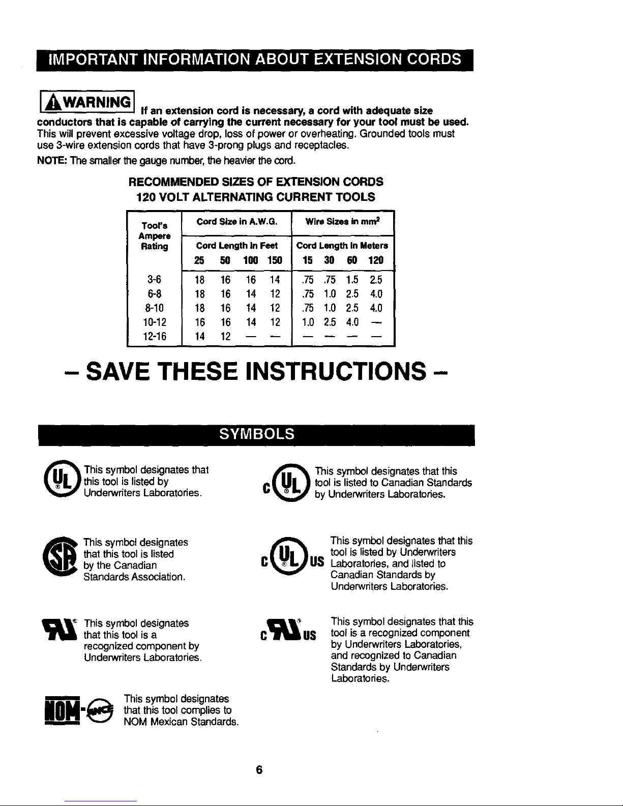
I WARNING I If an extension cord is necessary, s cord with adequate size
conductors that is capable of carrying the current necessary for your tool must be used.
This will prevent excessive voltage drop, loss of power or overheating. Grounded tools must
use 3-wire extension cords that have 3-prong plugs and receptacles.
NOTE: The smallerthe gauge number,the heavierthe cord.
RECOMMENDED SIZES OF EXTENSION CORDS
120 VOLT ALTERNATING CURRENT TOOLS
Tool's
Ampere
Rating
3-6
6-8
8-10
10-12
12-16
Cord Size in A.W.G. Wire Sizes in mm=
Cord Length in Feet
25 50 100 150
18 16 16 14
18 16 14 12
18 16 14 12
16 16 14 12
14 12
Cord Length In Meters
15 38 60 120
,75 ,75 1.5 2.5
.75 1.0 2.5 4.0
.75 1.0 2.5 4,0
1.0 2,5 4.0
- SAVE THESE INSTRUCTIONS-
(_ his symbol designates that
this tool is listed by
Underwriters Laboratories.
This symbol designates that this
_| I_1_ ) tool is listedto Canadian Standards
"_' by Underwriters Laboratories.
This symbol designates
that this tool is listed
by the Canadian
Standards Association.
This symbol designates that this
tool is listed by Underwriters
Laboratories, and listed to
Canadian Standards by
Underwriters Laboratories.
This symbol designates
that this too! is a
recognized component by
Underwriters Laboratories.
n
UOH-@
This symbol designates
that this tool complies to
NOM Mexican Standards.
c us
This symbol designates that this
tool is a recognized component
by Underwriters Laboratories,
and recognized to Canadian
Standards by Underwriters
Laboratories.
6

IMPORTANT: Some of the following symbols may be used on your tool. Please study them
and learn their meaning. Proper interpretation of these symbols will allow you to operate the
tool better and safer.
Symbol Name Designation/Explanation
V Volts Voltage (potential)
A Amperes Current
Hz Hertz Frequency (cycles per second)
W Watt Power
kg Kilograms Weight
rain ;Minutes []me
s Seconds Time
O Diameter Size of drillbits, grindingwheels,
etc.
no No load speed Rotational speed, at no load
.../min Revolutions or reciprocation Revolutions, strokes, surface
per minute speed, orbits, etc. per minute
0 Off position Zero speed, zero torque...
1, 2, 3.... Selector settings Speed, torque or position settings
I, II, III, Higher number means greater
speed
o._ Infinitelyvariable selector with off Speed is increasing from 0 setting
"_ Arrow Action in the direction of arrow
Alternating current Type or a characteristicof current
= Directcurrent Type or a characteristicof current
Alternating ordirect current Type or a characteristicof current
[] Class II construction Designates Double Insulated
Construction tools
(_) Earthing terminal Grounding terminal
Warning symbol Alerts user to warning messages
Ni-Cad RBRC seal Designates Ni-Cad battery
recycling program
7
The following Craftsman accessories are available separately for use with this router table:
9-25468 (9-70766 in Canada):
Craftsman Guide Master Router Table
Push Shoe with Hold Down Stick
• Ideal for handling small workpieces on a
router table
• Aids in accurate measurement and router
table set-up
• Transforms into a miter gauge
• Provides a quick set-up for making 1/2"
sliding dovetail joints
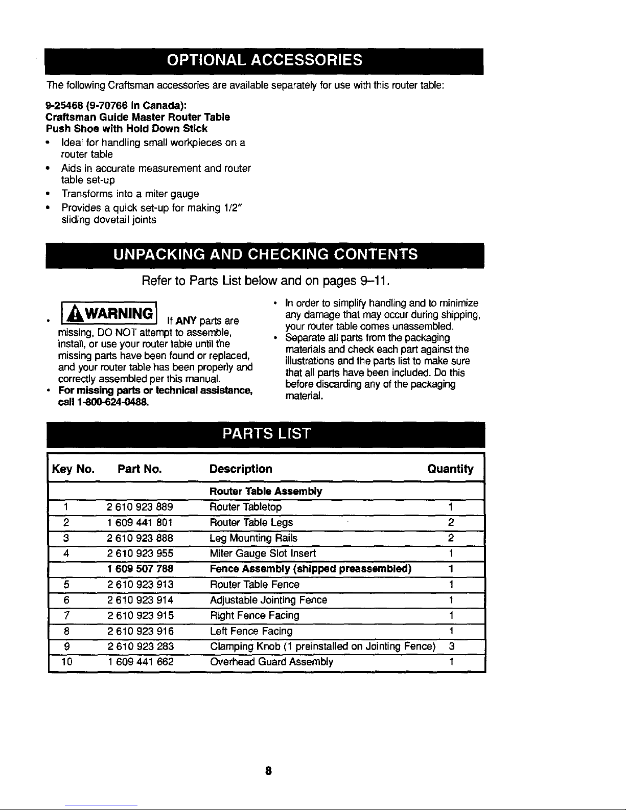
Refer to Parts List below and on pages 9-11.
I WARNING] IfANYparts are
missing, DO NOT attempt to assemble,
install, or use your router table until the
missing parts have been found or replaced,
and your router table has been properly and
correctly assembled per this manual,
For missing parts or technical assistance,
call 1-800-624-0488.
• Inorder to simplify handling and to minimize
any damage that may occur during shipping,
your router table comes unassembled.
• Separate all parts from the packaging
materials and check each part against the
illustrations and the parts list to make sure
that all parts have been included. Do this
before discarding any of the packaging
material.
Key No. Part No. Description Quantity
Router Table Assembly
1 2 610 923 889 Router Tabletop 1
2 1 609 441 801 Router Table Legs 2
3 2 610 923 888 Leg Mounting Rails 2
4 2 610 923 955 Miter Gauge Slot Insert 1
1 609 507 788 Fence Assembly (shipped preassembled) 1
5 2 610 923 913 Router Table Fence 1
6 2 610 923 914 Adjustable Jointing Fence 1
7 2 610 923 915 Right Fence Facing 1
8 2 610 923 916 Left Fence Facing 1
9 2 610 923 283 Clamping Knob (1 preinstalled on Jeinting Fence) 3
10 1 609 441 662 Overhead Guard Assembly 1
8
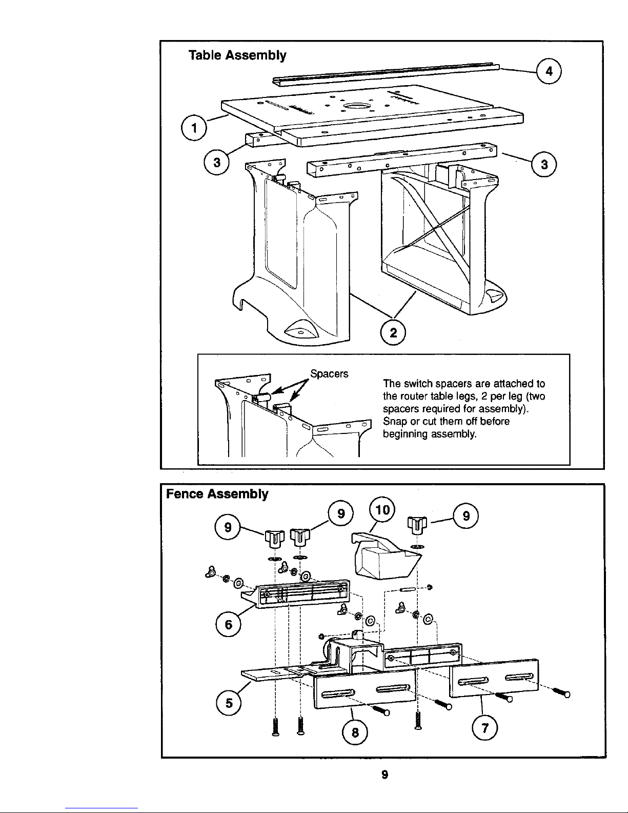
Table Assembly
®
The switch spacers are attached to
the router table legs, 2 per leg (two
spacers required for assembly).
Snap or cut them off before
beginning assembly.
Fence Assembly
9
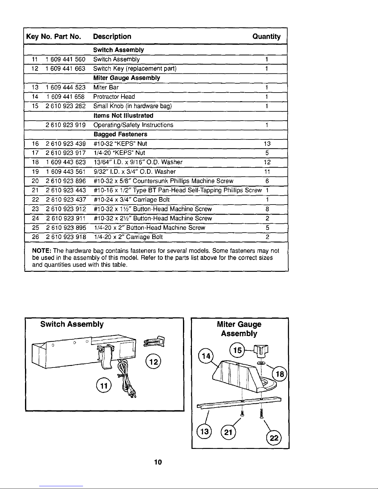
Key No. Part No. Description Quantity
Switch Assembly
11 1 609 441 560 Switch Assembly 1
12 1 609 441 663 Switch Key (replacement part) 1
Miter Gauge Assembly
13 1609444523 Miter Bar 1
14 1 609 441 658 Protractor Head 1
15 2 610 923 282 Small Knob (in hardware bag) 1
Items Not Illustrated
2 610 923 919 Operating/Safety Instructions 1
Bagged Fasteners
16 2610923439 #10-32"KEPS"Nut 13
17 2610 923 917 1i4-20"KEPS" Nut 5
18 1 609 443 623 13/64" I.D. x 9/16"O.D. Washer 12
19 1 609 443 561 9/32" I.D. x 3/4" O.D. Washer 11
20 2 610 923 896 #10-32 x 5/8" Countersunk Phillips Machine Screw 6
21 2 610 923 443 #10-16 x 1/2" Type BT Pan-Head Self-Tapping Phillips Screw 1
22 2 610 923 437 #10-24 x 3/4" Carriage Bolt 1
23 2 610 923 912 #10-32 x 1V2" Button-Head Machine Screw 8
24 2 610 923 911 #10-32 x 21/2" Button-Head Machine Screw 2
25 2 610 923 895 1/4-20 x 2"B_tton-Head Machine Screw 5
26 2610923918 1/4-20 x 2" Carriage Bolt 2
NOTE; The hardware bag contains fasteners for several models. Some fasteners may not
be used in the assembly of this model. Refer to the parts list above for the correct sizes
and quantities used with this table.
Switch Assembly
®
@
Miter Gauge
Assembly
10

@
(16) #10-32
KEPS Nut
@
(17) 1/4-20
KEPS Nut
©
(18) 13/64" I.D. x
9/I6" O.D. Washer
(19) 9/32" I.D. x 3/4"
O.D. Washer
(20) #10-32 x 5/8"
Countersunk Machine
Screw
(21) #10-16 x 1/2"
Type BT Phillips
Self-Tapping Screw
(22) #10-24 x 3/4"
Carriage Bolt
(23) #10-32 x 1W"
Button-Head Phillips
Machine Screw
(24) #10-32 x 2W" Button-Head
Phillips Machine Screw
(25) 1/4-20 x 2" Button-Head
Phillips Machine Screw
(26) 1/4-20 x 2" Carriage Bolt
11
TOOLS REQUIRED (not included)
• Phillips screwdriver
• 3/8" and 7/16" wrenches
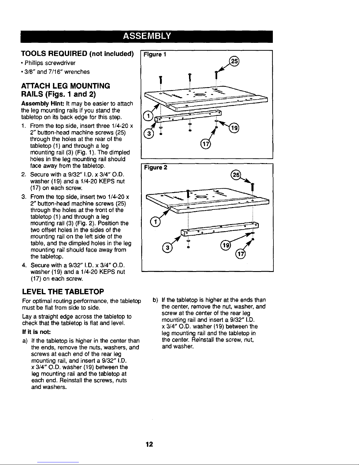
ATTACH LEG MOUNTING
RAILS (Figs. 1 and 2)
Assembly Hint: It may be easier to attach
the leg mounting rails if you stand the
tabletop on its back edge for this step.
1. From the top side, insert three 1/4-20 x
2" button-heed machine screws (25)
through the holes at the rear of the
tabletop (1) and through a leg
mounting rail (3) (Fig. 1). The dimpled
holes in the leg mounting rail should
face away from the tabletop,
2, Secure with a 9/32" I.D. x 3/4" O,D.
washer (19) and a 1/4-20 KEPS nut
(17) on each screw.
3. From the top side, insert two 1/4-20 x
2" button-head machine screws (25)
through the holes at the front of the
tabletop (1) and through a leg
mounting rail (3) (Fig. 2). Position the
two offset holes in the sides of the
mounting rail on the left side of the
table, and the dimpled holes in the leg
mounting rail should face away from
the tabletop.
4. Secure with a 9/32" I.D. x 3/4" O.D.
washer (19) and a 1/4-20 KEPS nut
(17) on each screw.
LEVEL THE TABLETOP
For optimal routing performance, the tabletop
must be flat from side to side,
Lay a straight edge across the tabletop to
check that the tabletop is flat and level.
If it is not:
a) If the tabletop is higher in the center than
the ends, remove the nuts, washers, and
screws at each end of the rear leg
mounting rail, and insert a 9/32" I.D.
x 3/4" O.D. washer (19) between the
leg mounting rail and the tabletop at
each end. Reinstall the screws, nuts
and washers.
'url'
Figure 2
b) If the tabletop is higher at the ends than
the center, remove the nut, washer, and
screw at the center of the rear leg
mounting rail and insert a 9/32" I.D.
x 3/4" O.D. washer (19) between the
leg mounting rail and the tabletop in
the center. Reinstall the screw, nut,
and washer.
12
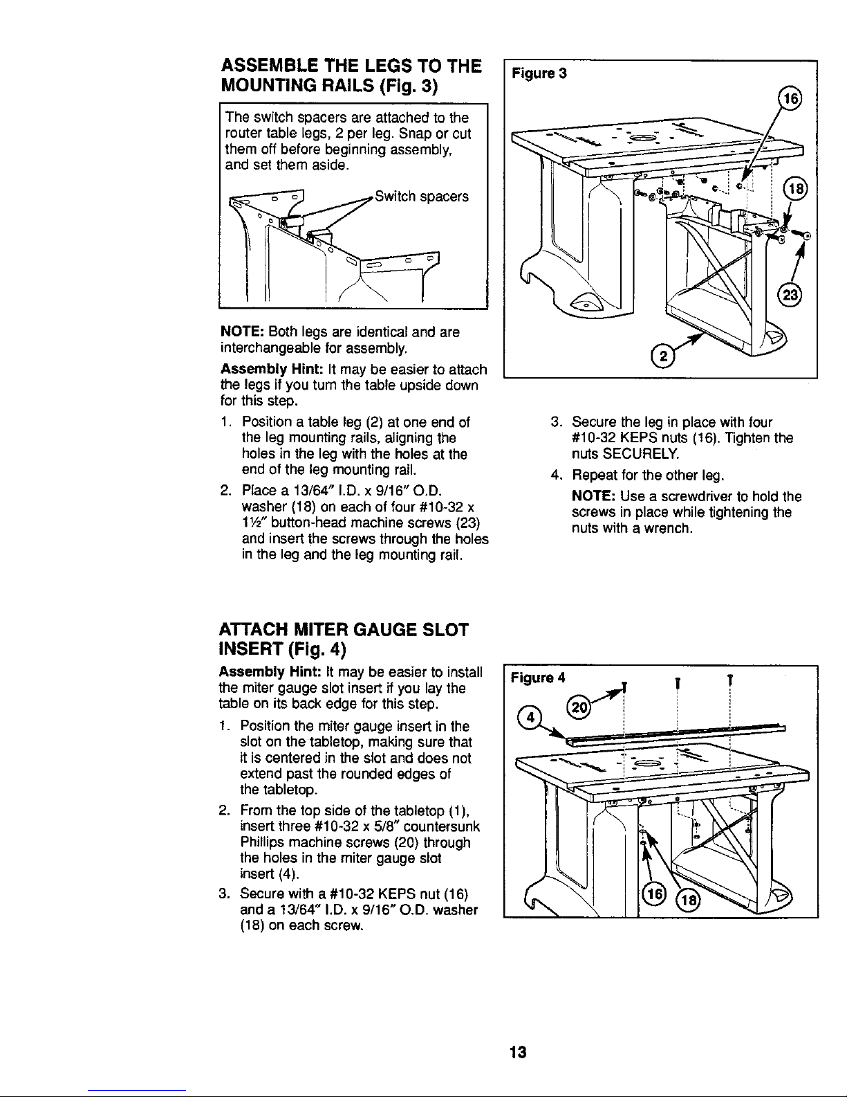
ASSEMBLE THE LEGS TO THE
MOUNTING RAILS (Fig. 3)
The switch spacers are attached to the
router table legs, 2 per leg. Snap or cut
them off before beginning assembly,
and set them aside.
NOTE: Both legs are identical and are
interchangeable for assembly.
Assembly Hint: It may be easier to attach
the legs if you turn the table upside down
for this step.
1. Position a table leg (2) at one end of
the leg mounting rails, aligning the
holes in the leg with the holes at the
end of the leg mounting rail.
2. Place a 13/64" I.D. x 9/16" O.D.
washer (18) on each of four #10-32 x
11/2"button-head machine screws (23)
and insert the screws through the holes
in the leg and the leg mounting rail.
Figure 3
3. Secure the leg in place with four
#10-32 KEPS nuts (16). "l]ghten the
nuts SECURELY.
4. Repeat for the other leg.
NOTE: Use a screwdriver to hold the
screws in place while tightening the
nuts with a wrench.
ATTACH MITER GAUGE SLOT
INSERT (Fig, 4)
Assembly Hint: It may be easier to install
the miter gauge slot insert if you lay the
table on its back edge for this step.
1. Position the miter gauge insert in the
slot on the tabletop, making sure that
it is centered in the slot and does not
extend past the rounded edges of
the tabletop.
2. From the top side of the tabletop (1),
insert three #10-32 x 5/8" countersunk
Phillips machine screws (20) through
the holes in the miter gauge slot
insert (4).
3. Secure with a #10-32 KEPS nut (16)
and a 13/64' I.D. x 9/16" O.D. washer
(18) on each screw.
13
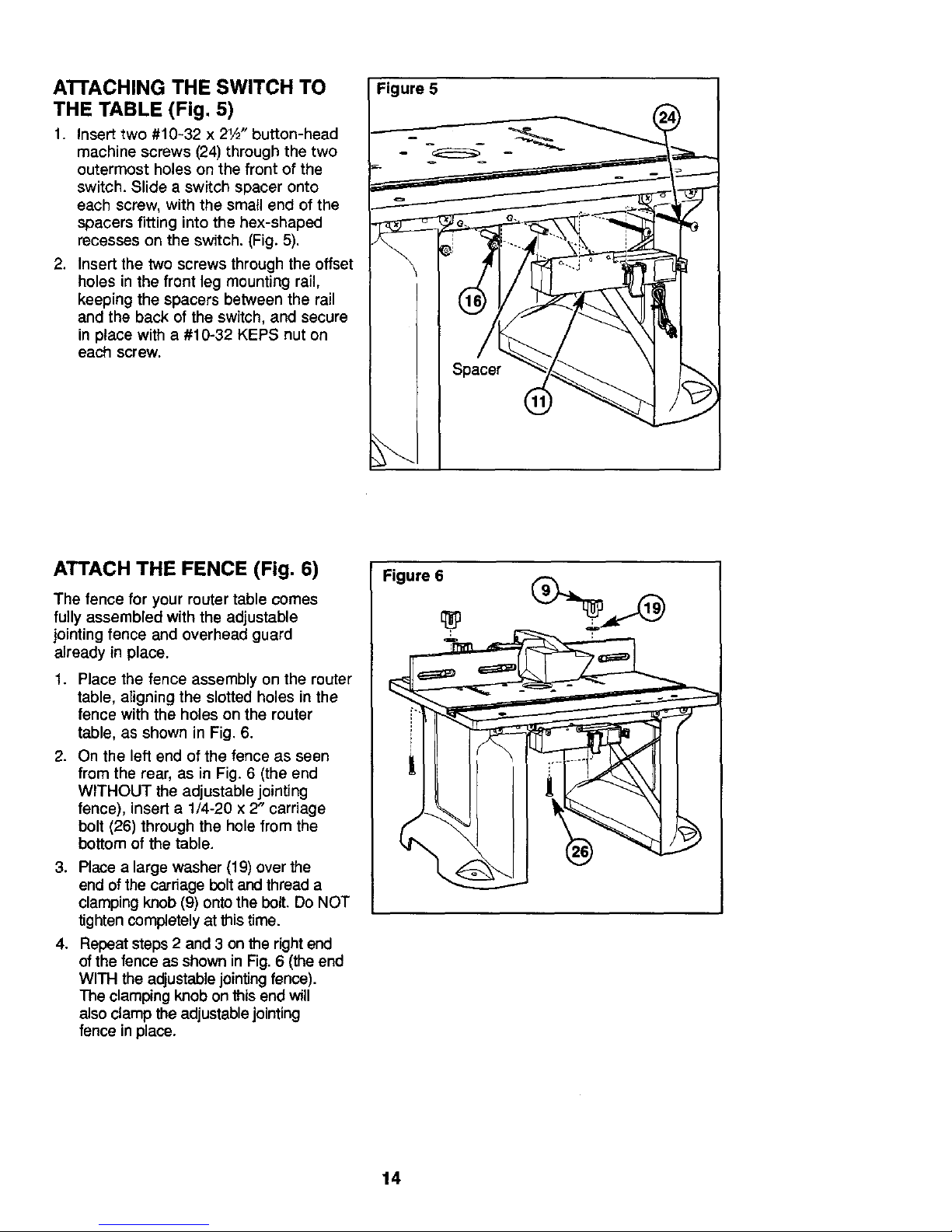
ATrACHING THE SWITCH TO
THE TABLE (Fig. 5)
1. Insert two #10-32 x 21/2"button-head
machine screws (24) through the two
outermost holes on the front of the
switch. Slide a switch spacer onto
each screw, with the small end of the
spacers fitting into the hex-shaped
recesses on the switch. (Fig. 5).
2. Insert the two screws through the offset
holes in the front leg mounting rail,
keeping the spacers between the rail
and the back of the switch, and secure
in place with a #10-32 KEPS nut on
each screw.
Spacer
ATTACH THE FENCE (Fig. 6)
The fence for your router table comes
fully assembled with the adjustable
jointing fence and overhead guard
already in place.
1. Place the fence assembly on the router
table, aligning the slotted holes in the
fence with the holes on the router
table, as shown in Fig. 6.
2. On the left end of the fence as seen
from the rear, as in Fig. 6 (the end
WITHOUT the adjustable jcinting
fence), insert a 1/4-20 x 2" carriage
bolt (26) through the hole from the
bottom of the table.
3. Place a large washer (19) over the
end of the carriage bolt and thread a
clamping knob (9) onto the bolt. Do NOT
tighten completely at thistime.
4. Repeat steps 2 and 3 on the right end
of the fence as shown in Fig. 6 (the end
WITH the adjustable jointing fence).
me clamping knob on this end will
also clamp the adjustable jointing
fence in place.
Figure 6
14
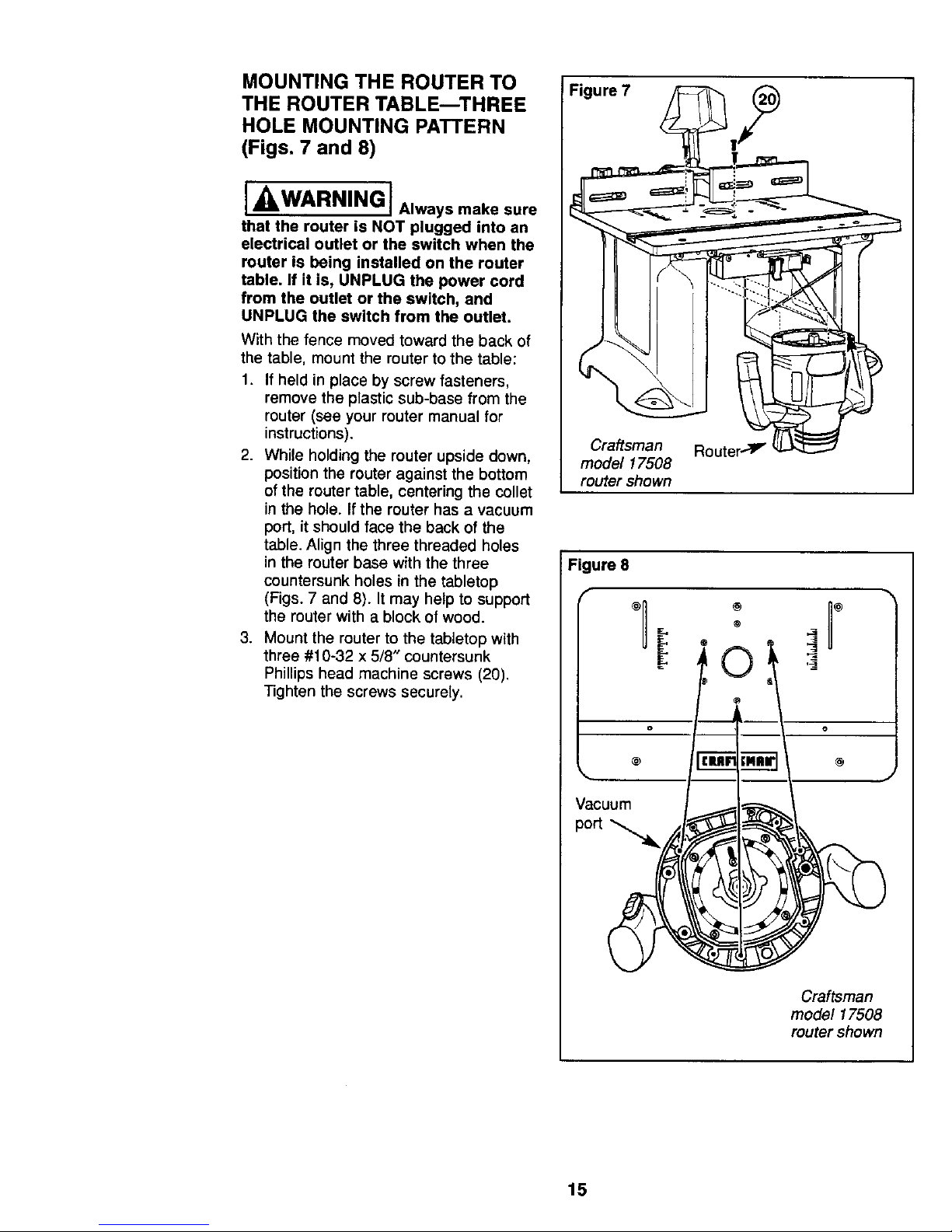
MOUNTING THE ROUTER TO
THE ROUTER TABLE--THREE
HOLE MOUNTING PATTERN
(Figs. 7 and 8)
I_WARNINGI Alwaysmakesure
that the router is NOT plugged into an
electrical outlet or the switch when the
router is being installed on the router
table. If it is, UNPLUG the power cord
from the outlet or the switch, and
UNPLUG the switch from the outlet.
With the fence moved toward the back of
the table, mount the router to the table:
1. If held in place by screw fasteners,
remove the plastic sub-base from the
router (see your router manual for
instructions).
2. While holding the router upside down,
position the router against the bottom
of the router table, centering the collet
in the hole. If the router has a vacuum
port, it should face the back of the
table. Align the three threaded holes
in the router base with the three
countersunk holes in the tabletop
(Figs. 7 and 8). It may help to support
the router with a block of wood.
3. Mount the router to the tabletop with
three #10-32 x 5/8" countersunk
Phillips head machine screws (20).
Tighten the screws securely.
!Figure 7 _ _li._bi_
Craftsman Router_V"
model 17508
router shown
I Figure 8
I/
:
p a oum
15
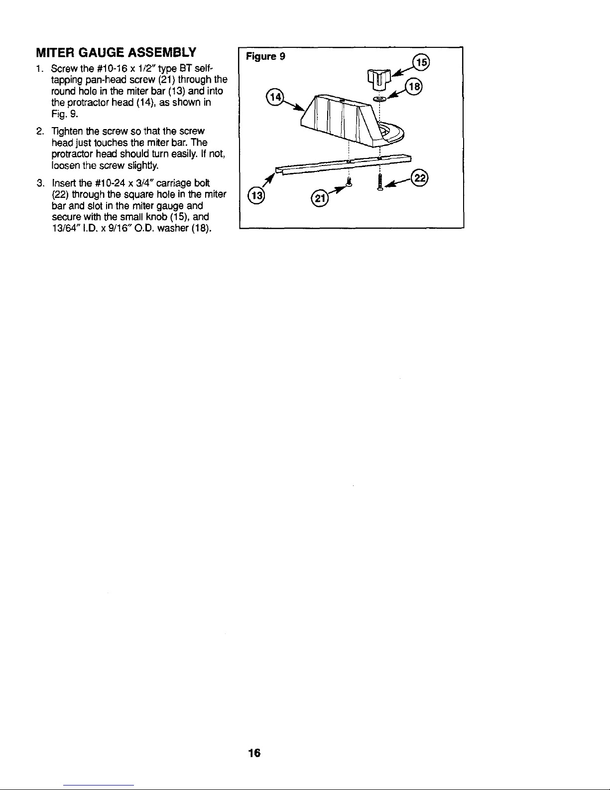
MITER GAUGE ASSEMBLY
1. Screw the #10-16 x 1/2" type BT self-
tapping pan-head screw (21) through the
round hole in the miter bar (13) and into
the protractor head (14), as shown in
Fig. 9.
2. "Nghten the screw so that the screw
head just touches the miter bar. The
protractor head should turn easily. If not,
loosen the screw slightZy.
3. Insert the #10-24 x 3/4" carriage bolt
(22) through the square hole in the miter
bar and slot in the miter gauge and
secure with the small knob (15), and
13/64" I.D. x 9/16" O.D. washer (18).
Figure 9 _[_9
16
MOUNTING THE ROUTER TABLE TO A
WORK SURFACE OR WORKBENCH
I_II_.WARNING, The router table
must always be FIRMLY and SECURELY
mounted to a work surface before use.
Failure to do so could cause the muter
table to tip over or slide, resulting in
property damage and/or serious
personal injury.
TOOLS REQUIRED
(not included)
• Phillips screwdriver
• Small sized adjustable wrench
• Electric or hand drill with drill bits
(depending on mounting method used)
• Fasteners (not included):
• 4 #10-18 x 13/4" (rain. length)
pan-head wood screws and 4
washers (for solid wood work
surfaces or workbenches), or
• 4 3/16" pan head machine screws,
8 washers, and hex nuts.
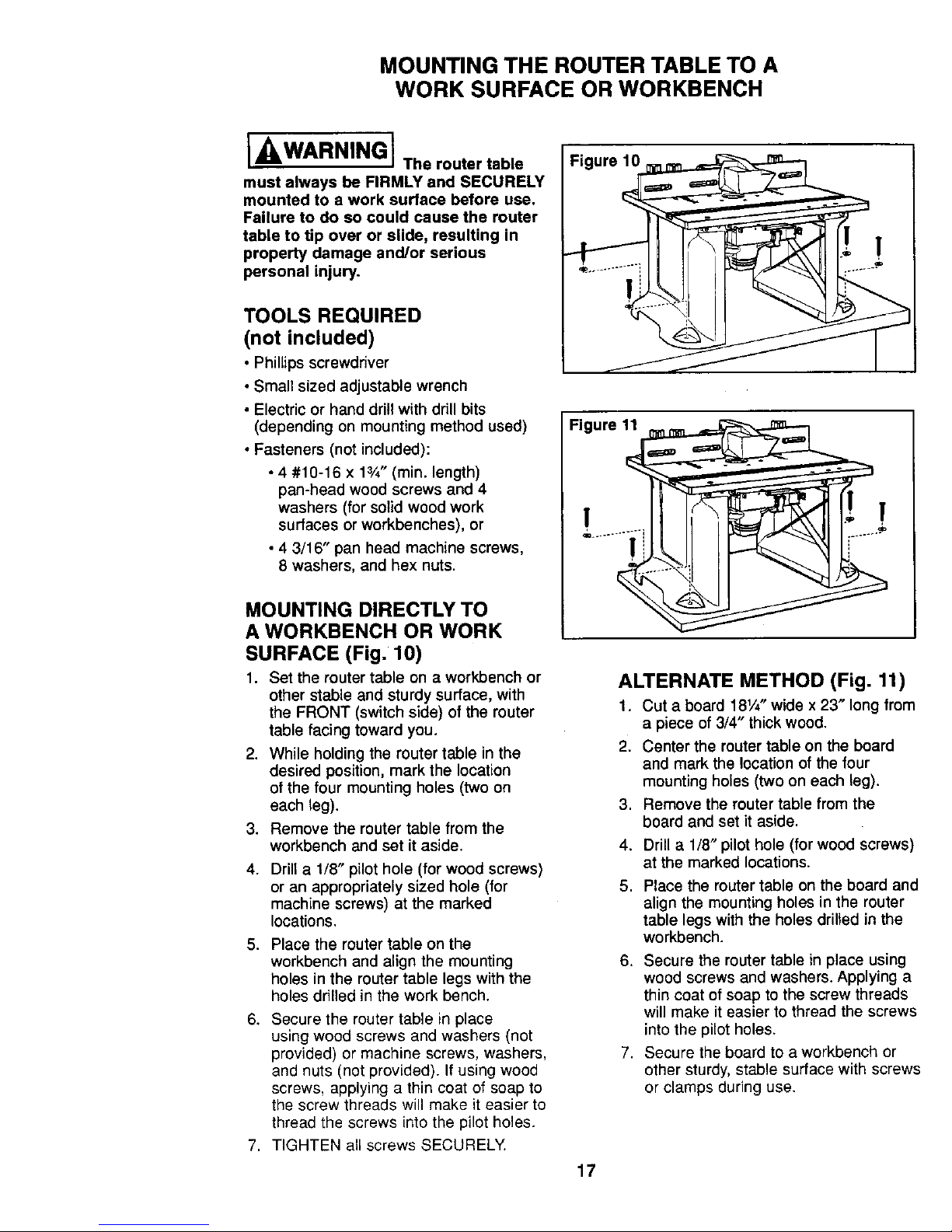
MOUNTING DIRECTLY TO
A WORKBENCH OR WORK
SURFACE (Fig. 10)
1. Set the router table on a workbench or
other stable and sturdy surface, with
the FRONT (switch side) of the router
table facing toward you.
2. While holding the router table in the
desired position, mark the location
of the four mounting holes (two on
each leg).
3. Remove the router table from the
workbench and set it aside.
4. Drill a 1/8" pilot hole (for wood screws)
or an appropriately sized hole (for
machine screws) at the marked
locations.
5. Place the router table on the
workbench and align the mounting
holes in the router table legs with the
holes drilled in the work bench.
6. Secure the router table in place
using wood screws and washers (not
provided) or machine screws, washers,
and nuts (not provided). If using wood
screws, applying a thin coat of soap to
the screw threads will make it easier to
thread the screws into the pilot holes.
7. TIGHTEN all screws SECURELY
Figure 10
Figure 1_
ALTERNATE METHOD (Fig. 11)
1. Cut a board 181/4"wide x 23" long from
a piece of 3/4" thickwood.
2. Center the router table on the board
and mark the location of the four
mounting holes (two on each leg).
3. Remove the router table from the
board and set it aside.
4. Drill a 1/8" pilot hole (for wood screws)
at the marked locations.
5. Place the router table on the board and
align the mounting holes in the router
table legs with the holes drilled in the
workbench.
6. Secure the router table in place using
wood screws and washers. Applying a
thin coat of soap to the screw threads
will make it easier to thread the screws
into the pilot holes.
7. Secure the board to aworkbench or
other sturdy, stable surface with screws
or clamps during use.
17
SWITCH INSTRUCTIONS
ELECTRICAL REQUIREMENTS
A 14 gauge (or heavier) three-wire extension
cord with a three-hole grounding receptacle
and three-hole grounding plug is to be used
for connecting the switch to an electrical
outlet. Do not use an extension cord longer
than 25 feet (8 meters).
Damaged or worn extension cords
are not to be used and are to be
replaced immediately,
The electrical cord at the back of the switch
will accept three-hole extension cords.
The electrical receptacles at the back of the
switch will accept either three-prong or two-
prong plugs from a router or accessory.
In the event of a malfunction or breakdown,
grounding provides the path of least
resistance for electrical current in order to
reduce the risk of electrical shock. This switch
box is equipped with an electrical cord that
has an equipment grounding connector and
a grounding plug.
The extension cord must be plugged into a
matching outlet that has been installed by
a licensed electrician and grounded in
accordance with all local codes and
ordinances.
DO NOT modify the plug from the switch if it
does not plug into the extension cord. Obtain
an extension cord with the proper outlet.
Improper connection of the equipment
grounding conductor can result in risk of
an electrical shock. The conductor with
insulationthat has a green outer surface, with
or without yellow stripes, is the equipment
groundingconductor.
DO NOT CONNECT THE EQUIPMENT
GROUNDING CONDUCTOR TO A LIVE
TERMINAL.
Check with a licensed electrician if the
grounding instructions are not completely
understood, or if there is doubt as to whether
the electrical outlet or extension cord is
properly grounded.
Ii ,.,WARNING i Donotpermit
fingers to touch terminals of the plug
when plugging it into or removing it
from the outlet.
J_WARNING J if notproperly
grounded, a power tool can present
potential hazards of electrical shock,
which can possibly result in SERIOUS
BODILY INJURY OR death, particularly
when used in a damp location, in
proximity to plumbing or out of doors.
If an electrical shock occurs, there is always
the potential of a secondary hazard, such as
your hands contacting the router bit, or falling
down or against an object.
J_kWARNING Jusetheswitchbox
only when properly assembled to the
router table. Use only with a router that
has also been properly installed on a
properly assembled router table.
Ii,.,WARNING i The switch has a
rating of 15 amps. Do NOT exceed a total
combined rating of 15 amps when
connecting the router and any
accessories such as a light or
wet/dry vacuum.
18
CONNECTING THE ROUTER
POWER CORD TO THE SWITCH
I, /LWARNING ]
• Make sure that the switch power cord is
not plugged into any electrical outlet at
this time. If it is, unplug it.
• Make sure that the router switch is in
the OFF position.
1. Plug the router power cord into one of
the electrical outlets on the back of the
switch case.
2. Form the excess power cord into a coil.
3. Wrap two pieces of friction tape or strong
cord around the coiled cord at opposite
sides of the coil.
4. Allow some slack so that the cord does
not become stretched when it is plugged
into the switch box outlets.
5. If desired, at this time plug the power
cord from an accessory, such as a
wet/dry vac or light, into the other outlet.
I WARNING I Make sure that
power cords from the router, accessories,
the switch case, and the extension cord
DO NOT and CANNOT come in contact
with the router or any moving parts of
the router.
• This switch has a 15 amp rating and is
Intended only for turning the router and
connected accessories such as a
wetJdry vacuum "ON" and "OFF".
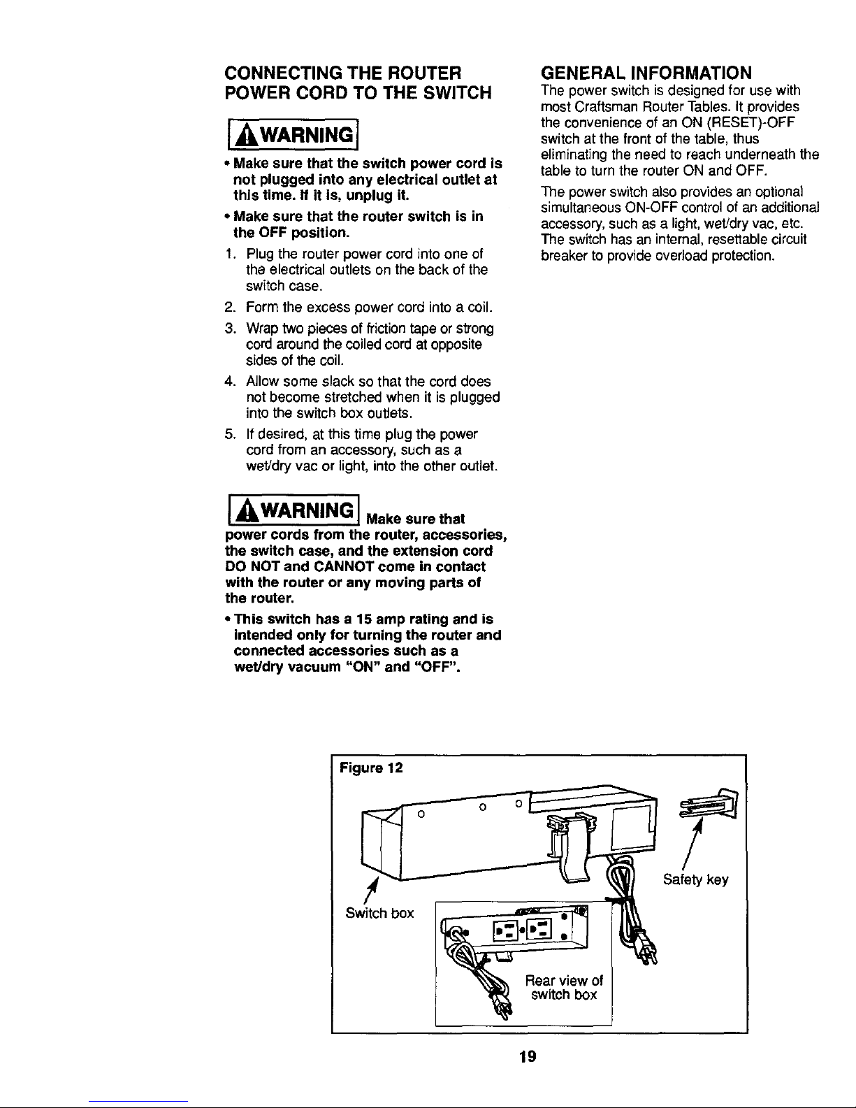
GENERAL INFORMATION
The power switch is designed for use with
most Craftsman Router Tables, It provides
the convenience of an ON (RESET)-OFF
switch at the front of the table, thus
eliminating the need to reach underneath the
table to turn the router ON and OFF.
The power switch also provides an optional
simultaneous ON-OFF control of an additional
accessory, such as a light, wet/dry vac, etc.
The switch has an internal, resettable circuit
breaker to provide overload protection.
Figure 12
!_ Safety ke_y
Switch box
Rear view of
switch box
19
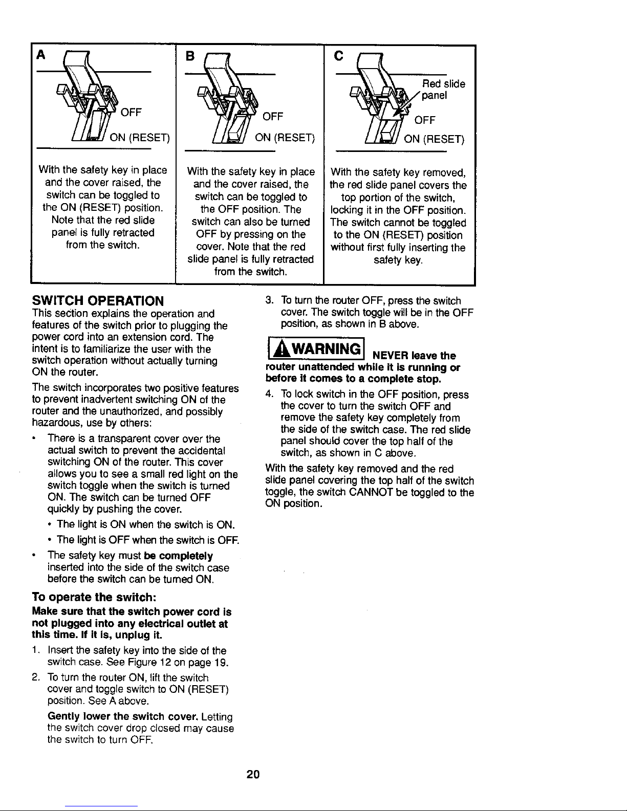
3N (RESET)
With the safety key in place
and the cover raised, the
switch can be toggled to
the ON (RESET) position.
Note that the red slide
panel is fully retracted
from the switch.
ON (RESET)
With the safety key in place
and the cover raised, the
switch can be toggled to
the OFF position. The
switch can also be turned
OFF by pressing on the
cover. Note that the red
slide panel is fully retracted
from the switch.
Red slide
panel
With the safety key removed,
the red slide panel covers the
top portion of the switch,
locking it in the OFF position.
The switch cannot be toggled
to the ON (RESET) position
without first fully inserting the
safety key.
SWITCH OPERATION
This section explains the operation and
features of the switch prior to plugging the
power cord into an extension cord. The
intent is to familiarize the user with the
switch operation without actually turning
ON the router.
The switch incorporates two positive features
to prevent inadvertent switching ON of the
router and the unauthorized, and possibly
hazardous, use by others:
There is a transparent cover over the
actual switch to prevent the accidental
switching ON of the router. This cover
allows you to see a small red light on the
switch toggle when the switch is turned
ON. The switch can be turned OFF
quickly by pushing the cover.
• The light is ON when the switch is ON.
• The light is OFF when the switch is OFF.
The safety key must be completely
inserted into the side of the switch case
before the switchcan be turned ON.
To operate the switch:
Make sure that the switch power cord is
not plugged into any electrical outlet at
this time. If it is, unplug it.
1. Insert the safety key into the side of the
switch case. See Figure 12 on page 19.
2. To turn the router ON, lift the switch
cover and toggle switch to ON (RESET)
position. See A above.
Gently lower the switch cover. Letting
the switch cover drop closed may cause
the switch to turn OFF.
3. To turn the muter OFF, press the switch
cover. The switch toggle will be in the OFF
position, as shown in B above.
I WARNINGI NEVER leave the
router unattended while it is running or
before it comes to a complete stop.
4. To lock switch in the OFF position, press
the cover to turn the switch OFF and
remove the safety key completely from
the side of the switch case. The red slide
panel should cover the top half of the
switch, as shown in C above.
With the safety key removed and the red
slide panel covering the top half of the switch
toggle, the switch CANNOT be toggled to the
ON position.
2O
I WARNING] Before proceeding
any further, make sure the switch on the
router is in the OFF position and the
switch is in the OFF position.
The switch power cord can now be
plugged into the extension cord.
J ,WARNING] Make sure that
power cords from the router, accessories,
the switch case, and the extension cord
DO NOT and CANNOT come in contact
with the router or any moving parts of
the router.
ROUTER AND SWITCH
OPERATION
This section explains operation of the
switch with the power cord plugged into
the extension cord.
The router will turn ON when the toggle
switch is toggled to the ON (RESET)
position.
1. Position the ON/OFF switch on the router
in the ON position. On certain touters this
will require the use of the switch trigger
and "LOCK-ON" button. (Consult router
owner's manual.) Make sure the switch
on the switch case is in the OFF
position when doing this.
2. To turn the router ON, lift the switch cover
and toggle the switch to the ON position.
See A on page 20.
3. To turn the router OFF, press the switch
cover. See B on page 20.
[ IkWARNINGJ NEVER leave the
router unattended while It is running or
before it comes to a complete stop.
NOTE: In the event of an overload, the
internal switch circuit breaker will trip the
switch to the OFF position.This will interrupt
power to the router and any accessory
plugged into the switch itself. If this occurs,
proceed as follows:
1. Unplug the switch cord from the
extension cord.
2. Remove the workpiece from the router
table.
3. Correct the cause of the overload
situation (i.e. the removal of too much
stock or use of too high a feed rate).
4. Plug the switch power cord into the
extension cord.
5. Restart the router as described in the
section ROUTER AND SWITCH
OPERATION.
WHEN THE ROUTER TABLE IS
NOT IN USE
1. Toggle the switch to the OFF position.
2. Remove the safety key.
3. Store the safety key in a safe location
where it is not available to children
and other unauthorized parsons.
4. Unplug the switch power cord from the
extension cord.
5. Remove the router bit from the router.
6. Positionthe router collet assembly below
the top of the router table.
NOTE: If the key should become lost or
damaged, replacement keys are available
from your local Sears outlet.
21
ATTACHING AND USING A
WET/DRY VACUUM
[ ILWARNING] Make sure that the
switch is OFF and UNPLUGGED before
plugging in a wet/dry vacuum or reaching
in the area under the table or near the
router bit]
The fence has a port for connecting a wet/dry
vac hose with a 2V2"nozzle. To attach, simply
push the nozzle into the port while holding
the fence assembly in place. The vacuum
can be plugged into the router table switch.
Be sure the cord does not interfere
with router operation.
II. CAUTION Operating the router
table without a wet/dry vec can result in an
excessive buildup of sawdust and wood
chips under the fence assembly and guard,
reducing the performance of the router table
and fence assembly.
RECOMMENDATION: To maximize
performance, regardless of whether a
wet/dry vec is being used, remove the
sawdust and wood chips from under the
fence assembly and guard as needed.
RECOMMENDATION: It is always a good
practice to keep the work area clean. As
necessary, remove any accumulated
sawdust and wood chips from the top of the
router table, as well as from the surrounding
work area and floor.
USING THE ROUTER TABLE
[ WARNINGJ Always make
sure that the router is turned OFF
and UNPLUGGED before making
any adjustments.
INSTALLING THE ROUTER BIT
(cu'n'ER)
Because of the large variation of router bits,
certain router bits may not always operate in
the desired manner with this router table.
To simplify installation of the router bit,
release the clamp that secures the router
motor assembly in the base and slide the
motor out of the base.
To ensure that the most popular bits will
perform satisfactorily, install the bit so that
the router collet engages 3/4" of the router
bit shank. If the shank of the router bit
bottoms out in the collet, back out the router
bit approximately 1/16" to allow for proper
tightening.
NEVER install router bits with less than
3/4" of shank engagement in the collet.
22
ADJUSTABLE JOINTING FENCE
(Fig. 13)
I- WARNING IAlways make sure
that the router is turned OFF and the
power cord UNPLUGGED before
making any adjustments.
The fence for your router table comes fully
assembled with the adjustable jointing
fence already in place.
To adjust the jolnting fence:
1. Loosen both the adjustable jointing
fence clamping knob and the fence
clamping knob on that side.
2. Slide the jointing fence forward or
backward in the guides to the desired
position.
3. 13ghten both clamping knobs.
To remove and reinstall the
jointing fence:
1. Loosen the fence clamping knobs
completely and remove the knobs and
washers from the carriage bolts. Hold
the carriage bolts for the fence from
underneath the table to keep them
from dropping.
2. Loosen the clamping knob on the
adjustable jointing fence completely,
and remove it and the washer from the
carriage bolt. Remove the carriage bolt
from the bottom of the fence and lift the
jointing fence out of the grooves on
the fence.
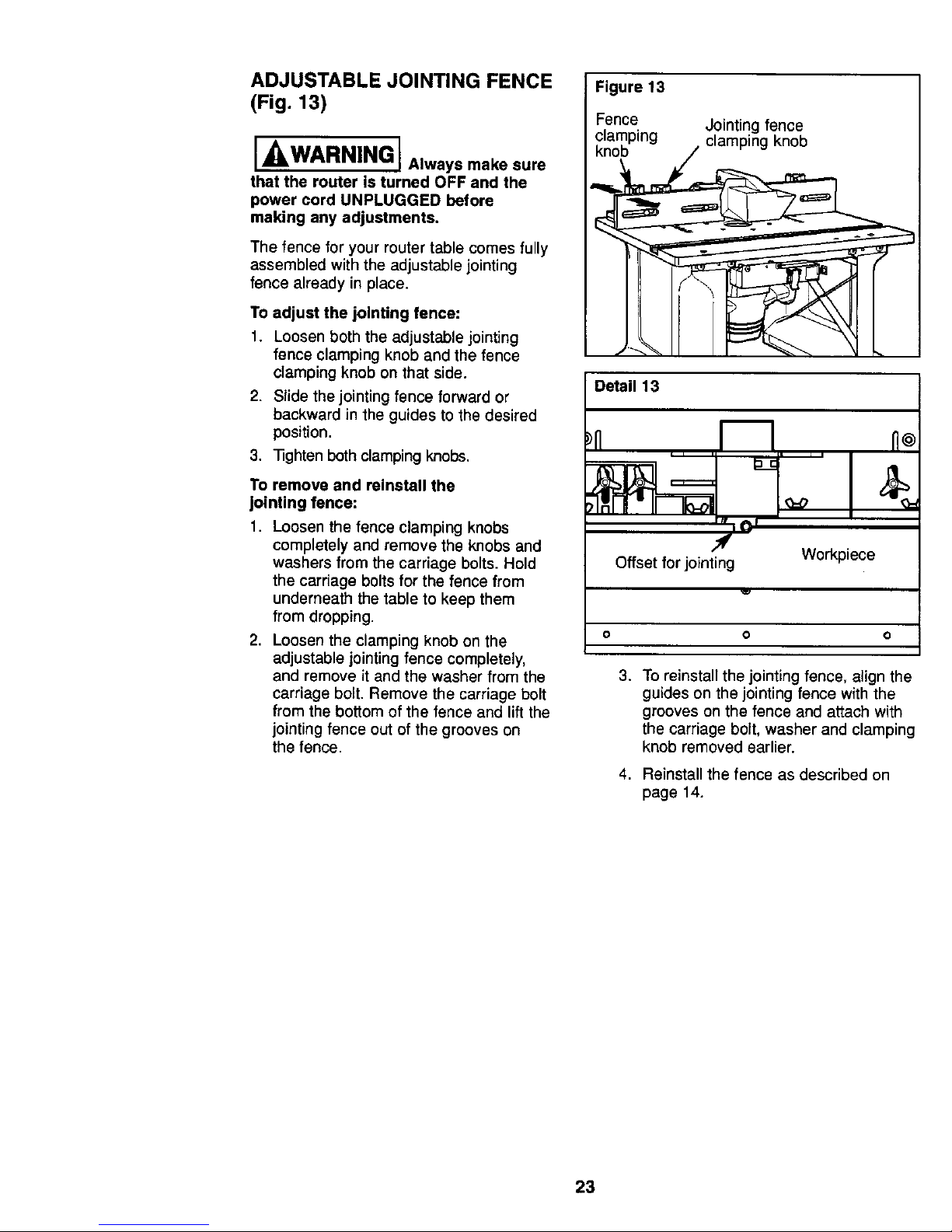
Figure 13
Fence Jointing fence
clamping clamping knob
knob
Detail 13
Offset for jointing Workpiece
O O O
3. To reinstall the jointlng fence, align the
guides on the jointing fence with the
grooves on the fence and attach with
the carriage bolt, washer and clamping
knob removed earlier.
4. Reinstall the fence as described on
page 14.
23
I_'WARNING I Always make sure
that the router is turned OFF and the
power cord UNPLUGGED before
making any adjustments.
I_WARNINGI For accuracy
in routing and improved control, the
workpiece should be held against the
router table fence when routing.
ADJUSTING THE FENCE
FACING
The right and left fence facings, identified
with "R" and "L" respectively, attach to the
front face of the router table fence, and
can be adjusted inward or outward from
the router bit, to allow proper clearance for
different sized bits. To provide the best
support during routing operations, the
fence facings should be as close to the bit
as possible without being able to come in
contact with the bit (typically about 1/4"
from the bit is a suitable distance).
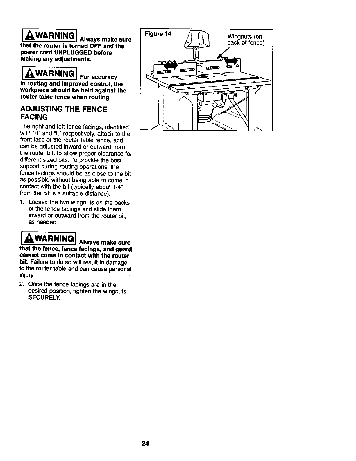
1. Loosen the two wingnuts on the backs
of the fence facings and slide them
inward or outward from the router bit,
as needed.
I _,WARNING I Alwaysmakesure
that the fence, fence facings, and guard
cannot come in contact with the router
bit. Failure to do so will result in damage
to the routertable and can cause personal
injury.
2. Once the fence facings are in the
desired position, tighten the wingnuts
SECURELY.
Figure 14
Wingnuts (on
back of fence)
24
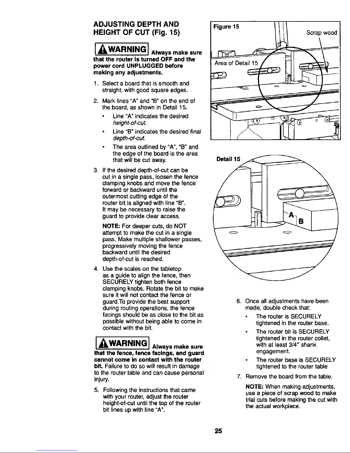
ADJUSTING DEPTH AND Figure15
HEIGHT OF CUT (Fig. 15)
I/kWARNING I Alwaysmake sure
that the router is turned OFF and the
power cord UNPLUGGED before
making any adjustments,
1. Select a board that is smooth and
straight, with good square edges.
2. Mark lines "A" and °B" on the end of
the board, as shown in Detail 15.
Line "A" indicates the desired
height-of-cut.
Line "B" indicates the desired final
depth-of-cut.
The area outlined by "A", "B" and
the edge of the board is the area
that will be cut away.
3. If the desired depth-of-cut can be
cut in a single pass, loosen the fence
clamping knobs and move the fence
forward or backward until the
outermost cutting edge of the
router bit is aligned with line =B".
It may be necessary to raise the
guard to provide clear access.
NOTE: For deeper cuts, do NOT
attempt to make the cut in a single
pass. Make multiple shallower passes,
progressively moving the fence
backward until the desired
depth-of-cut is reached.
4. Use the scales on the tabletop
as a guide to align the fence, then
SECURELY tighten both fence
clamping knobs. Rotate the bit to make
sure it will not contact the fence or
guard.To provide the best support
during routing operations, the fence
facings should be as close to the bit as
possible without being able to come in
contact with the bit.
I WARNING I Always make sure
that the fence, fence facings, and guard
cannot come in contact with the router
bit. Failure to do so will result in damage
to the router table and can cause personal
injury.
5. Following the instructions that came
with your router, adjust the router
height-of-cut until the top of the router
bit lines up with line "A".
Scrap wood
6. Once all adjustments have been
made, double check that:
The router is SECURELY
tightened in the router base.
The router bit is SECURELY
tightened in the router collet,
with at least 3/4" shank
engagement.
The router base is SECURELY
tightened to the router table
7. Remove the board from the table.
NOTE: When making adjustments,
use a piece of scrap wood to make
trial cuts before making the cut with
the actual workpiece.
25
ROUTING USING THE FENCE
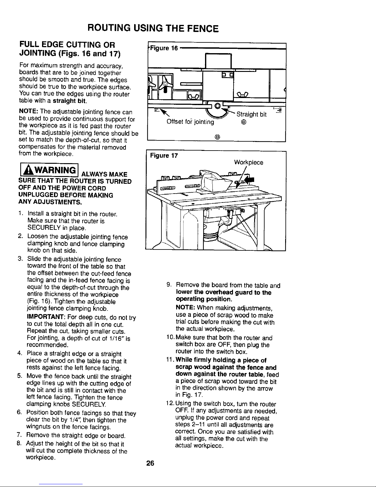
FULL EDGE CU]-I'ING OR
JOINTING (Figs. 16 and 17)
For maximum strength and accuracy,
boards that are to be joined together
should be smooth and true. The edges
should be true to the workpiece surface.
You can true the edges using the router
table with a straight bit.
NOTE: The adjustable jointing fence can
be used to provide continuous support for
the workpiece as it is fed past the router
bit. The adjustable jointing fence should be
set to match the depth-of-cut, so that it
compensates for the material removed
from the workpiece.
] WARNING I ALWAYSMAKE
SURE THAT THE ROUTER IS TURNED
OFF AND TIlE POWER CORD
UNPLUGGED BEFORE MAKING
ANY ADJUSTMENTS.
1. Install a straight bit in the router.
Make sure that the router is
SECURELY in p_ace.
2. Loosen the adjustable jointing fence
clamping knob and fence clamping
knob on that side.
3. Slide the adjustable jointing fence
toward the front of the table so that
the offset between the out-feed fence
facing and the in-feed fence facing is
equal to the depth-of-cut through the
entire thickness of the workpiece
(Fig. 16). Tighten the adjustable
jointing fence clamping knob.
IMPORTANT: For deep cuts, do not try
to cut the total depth all in one cut.
Repeat the cut, taking smaller cuts.
For jointing, a depth of cut of 1/16" is
recommended.
4. Ptace a straight edge or a straight
piece of wood on the table so that it
rests against the left fence facing.
5. Move the fence back until the straight
edge lines up with the cutting edge of
the bit and is still in contact with the
left fence facing. _ghten the fence
clamping knobs SECURELY.
6. Position both fence facings so that they
clear the bit by 1/4"_then tighten the
wingnuts on the fence facings.
7. Remove the straight edge or board.
8. Adjust the height of the bit so that it
will cut the complete thickness of the
workpiece.
•Figure 16
Offset fo_jointing
_=_ Straight bit
@
@
Figure 17
Workpiece
9. Remove the board from the table and
lower the overhead guard to the
operating position.
NOTE: When making adjustments,
use a piece of scrap wood to make
trial cuts before making the cut with
the actual workpiece.
10. Make sure that both the router and
switch box are OFF, then plug the
router into the switch box.
11. While firmly holding a piece of
scrap wood against the fence and
down against the router table, feed
a piece of scrap wood toward the bit
in the direction shown bythe arrow
in Fig. 17.
12.Using the switch box, turn the router
OFF. If any adjustments are needed,
unplug the power cord and repeat
steps 2-11 until all adjustments are
correct. Once you are satisfied with
all settings, make the cut with the
actual workpiece.
26
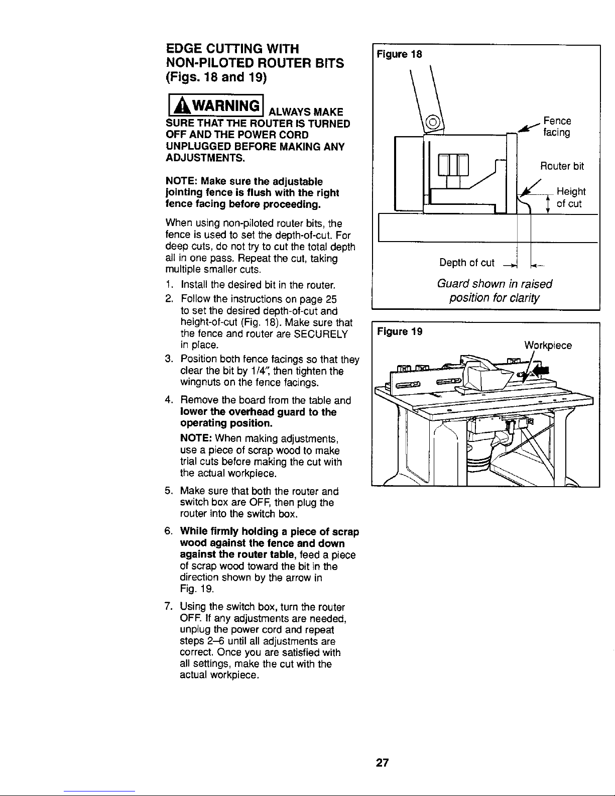
EDGE CUTTING WITH
NON-PILOTED ROUTER BITS
(Figs. 18 and 19)
[ WARNING] ALWAYS MAKE
SURE THAT THE ROUTER IS TURNED
OFF AND THE POWER CORD
UNPLUGGED BEFORE MAKING ANY
ADJUSTMENTS.
NOTE: Make sure the adjustable
jointing fence is flush with the right
fence facing before proceeding.
When using non-piloted router bits, the
fence is used to set the depth-of-cut. For
deep cuts, do not try to cut the total depth
all in one pass. Repeat the cut, taking
multiple smaller cuts.
1. Install the desired bit in the router.
2. Follow the instructions on page 25
to set the desired depth-of-cut and
height-of-cut (Fig. 18). Make sure that
the fence and router are SECURELY
in place.
3. Position both fence facings so that they
clear the bit by 1/4", then tighten the
wingnuts on the fence facings.
4. Remove the board from the table and
lower the overhead guard to the
operating position.
NOTE: When making adjustments,
use a piece of scrap wood to make
trial cuts before making the cut with
the actual workpiece.
5. Make sure that both the router and
switch box are OFF, then plug the
router into the switch box.
6. While firmly holding a piece of scrap
wood against the fence and down
against the router table, feed a piece
of scrap wood toward the bit in the
direction shown by the arrow in
Fig. 19.
7. Using the switch box, turn the router
OFF. If any adjustments are needed,
unplug the power cord and repeat
steps 2-6 until all adjustments are
correct. Once you are satisfied with
all settings, make the cut with the
actual workpiece.
Figure 18
Fence
facing
Router bit
Height
of cut
Depth of cut
Guard shown in raised
position for clarity
Figure 19
Workpiece
27
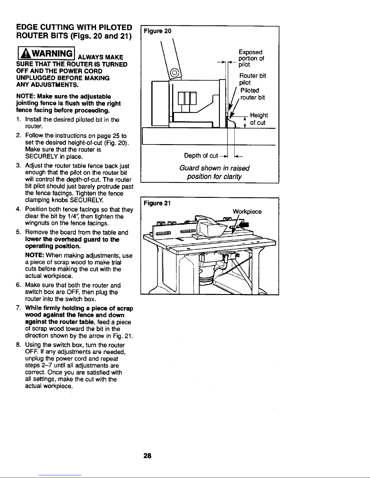
EDGE CUTTING WITH PILOTED
Figure 20
ROUTER BITS (Figs. 20 and 21)
I -_WARNING t ALWAYSMAKE
SURE THAT THE ROUTER IS TURNED
OFF AND THE POWER CORD
UNPLUGGED BEFORE MAKING
ANY ADJUSTMENTS.
NOTE: Make sure the adjustable
joinUng fence Is flush with the right
fence facing before proceeding.
1. Install the desired piloted bit in the
router.
2. Follow the instructions on page 25 to
set the desired height-of-cut (Fig. 20).
Make sure that the router is
SECURELY in place.
3. Adjustthe router table fence back just
enough that the pilot on the router bit
will control the depth-of-cut. The router
bit pilot should just barely protrude past
the fence facings. Tighten the fence
clamping knobs SECURELY.
4. Position both fence facings so that they
clear the bit by 1/4'_ then tighten the
wingnuts on the fence facings.
5. Remove the board from the table and
lower the overhead guard to the
operating position.
NOTE: When making adjustments, use
a piece of scrap wood to make trial
cuts before making the cut with the
actual workpiece.
6. Make sure that both the router and
switch box are OFF, then plug the
muter into the switch box.
7. While firmly holding a piece of scrap
wood against the fence and down
against the router table, feed a piece
of scrap wood toward the bit in the
direction shown by the arrow in Fig. 21.
8. Using the switch box, turn the router
OFF. If any adjustments are needed,
unplug the power cord and repeat
steps 2-7 until all adjustments are
correct. Once you are satisfied with
all settings, make the cut with the
actual workpiece.
Exposed
of
Router bit
F II pilot
I /II, P,o,%terb
I Height
Depth of cut _
Guard shown in raised
position for clarity
Figure 21
Workpiece
28
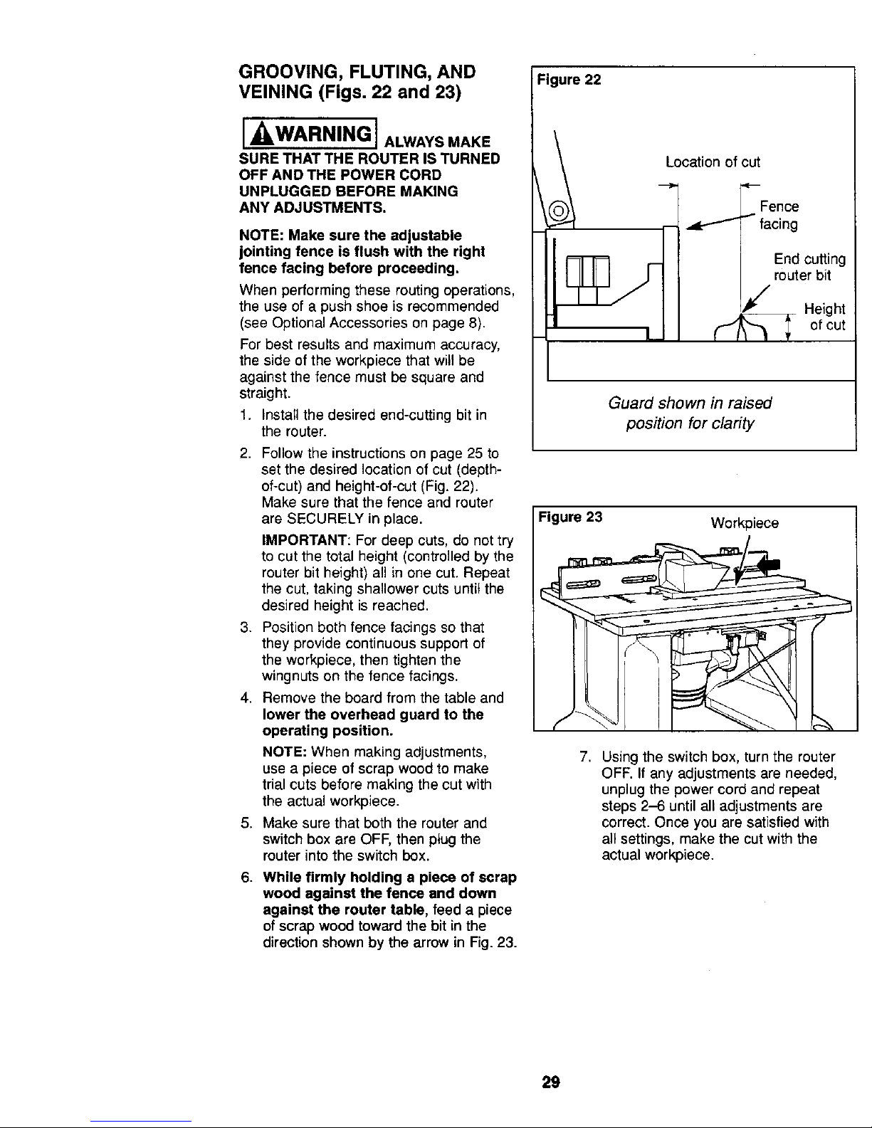
GROOVING, FLUTING, AND
VEINING (Figs. 22 and 23)
[ WARNING ] ALWAYSMAKE
SURE THAT THE ROUTER IS TURNED
OFF AND THE POWER CORD
UNPLUGGED BEFORE MAKING
ANY ADJUSTMENTS.
NOTE: Make sure the adjustable
jointing fence is flush with the right
fence facing before proceeding,
When performing these routing operations,
the use of a push shoe is recommended
(see Optional Accessories on page 8).
For best results and maximum accuracy,
the side of the workpiece that will be
against the fence must be square and
straight.
1. Install the desired end-cutting bit in
the router.
2. Follow the instructions on page 25 to
set the desired location of cut (depth-
of-cut) and height-of-cut (Fig. 22).
Make sure that the fence and router
are SECURELY in place.
IMPORTANT: For deep cuts, do not try
to cut the total height (controlled by the
router bit height) all in one cut. Repeat
the cut, taking shallower cuts until the
desired height is reached.
3. Position both fence facings so that
they provide continuous support of
the workpiece, then tighten the
wingnuts on the fence facings.
4. Remove the board from the table and
lower the overhead guard to the
operating position.
NOTE: When making adjustments,
use a piece of scrap wood to make
trial cuts before making the cut with
the actual workpiece.
5. Make sure that both the router and
switch box are OFF, then plug the
router into the switch box.
6. While firmly holding a piece of scrap
wood against the fence and down
against the router table, feed a piece
of scrap wood toward the bit in the
direction shown by the arrow in Fig. 23.
Figure 22
Location of cut
Fence
-- _ "_ facing
End cutting
router bit
_'/ Height
otcut
Guard shown in raised
position for clarity
Figure 23 Workpiece
(
7. Using the switch box, turn the router
OFF. If any adjustments are needed,
unplug the power cord and repeat
steps 2-6 until all adjustments are
correct. Once you are satisfied with
all settings, make the cut with the
actual workpiece.
29
 Loading...