

Craftsman 170.172440, 170.172450, 170.265610 Owner's Manual

Owner's Manual
I CRRFTSMRN°I
ALL-IN-ONE CUTTING TOOL
Model Nos.
170.172440
170.172450
170.265610
Caution:
Before using this product,
read this manual and follow •
all its Safety Rules and •
Operating Instructions.
Sears, Roebuck and Co., Hoffman Estates, IL 60179 U.S.A.
Safety
Operation
Maintenance
Parts
Espahol, (page 9)
Page
Warranty ..................................................... 2
Power Tool Safety Rules ...................................... 3-5
Symbols ..................................................... 6
Functional Description and Specifications ......................... 7-8
Assembly ................................................. 9-12
Operating Instructions ....................................... 13-16
Maintenance .............................................. 16-17
Accessories ................................................. 18
Espa_ol .................................................. 19-35
FULL ONE YEAR WARRANTY ON CRAFTSMAN
ALL-IN-ONE CUTTING TOOL
If this CRAFTSMAN All-In-One Cutting Tool fails to give complete
satisfaction within one year from the date of purchase, RETURN IT TO
THE NEAREST SEARS STORE OR OTHER CRAFTSMAN OUTLET IN
THE UNITED STATES, and Sears will replace it, free of charge.
If this CRAFTSMAN AlPln-One Cutting Tool is used for commercial or
rental purposes, this warranty applies for only 90 days from the date of
purchase.
This warranty gives you specific legal rights, and you may also have other
rights which vary from state to state.
Sears, Roebuck and Co., Dept. 817WA, Hoffman Estates, IL 60179
-2-
Read and understand all instructions. Failure to follow all instructions
listed below, may result in electric shock, fire and/or serious personal injury.
SAVE THESE INSTRUCTIONS
Work Area
Keep your work area clean and well lit.
Cluttered benches and dark areas invite
accidents.
Do not operate power tools in explosive
atmospheres, such as in the presence of
flammable liquids, gases, or dust. Power
tools create sparks which may ignite the dust
or fumes.
Keep by-standers, children, and visitors
away while operating a power tool.
Distractions can cause you to lose control.
Electrical Safety
Double Insulated tools are equipped with
a polarized plug (one blade is wider than
the other.) This plug will fit in a polarized
outlet only one way. If the plug does not
fit fully in the outlet, reverse the plug. If it
still does not fit, contact a qualified
electrician to install a polarized outlet. Do
not change the plug in any way. Double
Insulation _]eliminates the need for the three
wire grounded power cord and grounded
power supply system. Before plugging in the
tool, be certain the outlet voltage supplied is
within the voltage marked on the nameplate.
Do not use "AC only" rated tools with a DC
power supply.
Avoid body contact with grounded
surfaces such as pipes, radiators, ranges
and refrigerators. There is an increased risk
of electric shock if your body is grounded. If
operating the power tool in damp locations is
unavoidable, a Ground Fault Circuit Interrupter
must be used to supply the power to your tool.
Electrician's rubber gloves and footwear will
further enhance your personal safety.
Don't expose power tools to rain or wet
conditions. Water entering a power tool will
increase the risk of electric shock.
Do not abuse the cord. Never use the cord
to carry the tools or pull the plug from an
outlet. Keep cord away from heat, oil, sharp
edges or moving parts. Replace damaged
cords immediately. Damaged cords increase
the risk of electric shock.
When operating a power tool outside, use
an outdoor extension cord marked "W-A"
or "W." These cords are rated for outdoor use
and reduce the risk of electric shock. Refer to
"Recommended sizes of Extension Cords" in
the Accessory section of this manual.
Personal Safety
Stay alert, watch what you are doing and
use common sense when operating a
power tool. Do not use tool while tired or
under the influence of drugs, alcohol, or
medication. A moment of inattention while
operating power tools may result in serious
personal injury.
Dress properly. Do not wear loose clothing
or jewelry. Contain long hair. Keep your
hair, clothing, and gloves away from
moving parts. Loose clothes, jewelry, or long
hair can be caught in moving parts. Keep
handles dry, clean and free from oil and
grease.
Avoid accidental starting. Be sure switch is
"OFF" before plugging in. Carrying tools with
your finger on the switch or plugging in tools
that have the switch "ON" invites accidents.
Remove adjusting keys or wrenches before
turning the tool "ON". A wrench or a key that
is left attached to a rotating part of the tool may
result in personal injury.
Do not overreach. Keep proper footing and
balance at all times. Proper footing and
balance enables better control of the tool in
unexpected situations.
Use safety equipment. Always wear eye
protection. Dust mask, non-skid safety shoes,
hard hat, or hearing protection must be used
for appropriate conditions.
Tool Use and Care
use clamps or other practical way to
secure and support the workpiece to a
stable platform. Holding the work by hand or
against your body is unstable and may leadto
loss of control.
Do not force tool. Use the correct tool for
your application. The correct tool will do the
-3-

job better and safer at the rate for which it is
designed.
Do not use tool if switch does not turn it
"ON" or "OFF". Any tool thatcannot be
controlled with the switch is dangerous and
must be repaired.
Disconnect the plug from the power source
before making any adjustments, changing
accessories, or storing the tool. Such
preventive safety measures reducethe risk of
starting the tool accidentally.
Store idle tools out of reach of children and
other untrained persons. Tools are
dangerous in the hands of untrained users.
Maintain tools with care. Keep cutting tools
sharp and clean. Properly maintainedtools,
with sharp cutting edges are lesslikely to bind
and are easier to control. Any alteration or
modification is a misuse and may result in a
dangerous condition.
Check for misalignment or binding of
moving parts, breakage of parts, and any
other condition that may affect the tools
operation. If damaged, have the tool
serviced before using. Many accidents are
caused by poorly maintained tools. Develop a
periodic maintenance schedule for your tool.
Use only accessories that are recom-
mended by the manufacturer for your
model. Accessories that may be suitable for
one tool, may become hazardous when used
on another tool.
Service
Tool service must be performed only by
qualified repair personnel. Service or
maintenance performed by unqualified
personnel could result in a risk of injury. For
example: internal wires may be misplaced or
pinched, safety guard return springs may be
improperly mounted.
When servicing a tool, use only identical
replacement parts. Follow instructions in
the Maintenance section of this manual.
Use of unauthorized parts or failure to follow
Maintenance Instructions may create a risk of
electric shock or injury. Certain cleaning
agents such as gasoline, carbon tetrachloride,
ammonia, etc. may damage plastic parts.
Hold tool by insulated gripping surfaces
when performing an operation where the
cutting tool may contact hidden wiring or
its own cord. Contact with a "live" wire will
make exposed metal parts of the tool "live"
and shock the operator. If cutting into existing
walls or other blind areas where electrical
wiring may exist is unavoidable, disconnect
all fuses or circuit breakers feeding this
worksite.
Always make sure the work surface is free
from nails and other foreign objects.
Cutting into a nail can cause the bit and the
tool to jump and damage the bit.
Never hold the workpiece in one hand and
the tool in the other hand when in use.
Never place hands near or below cutting
surface. Clamping the material and guiding
the tool with both hands is safer.
Never lay workpiece on top of hard
surfaces, like concrete, stone, etc...
Protruding cutting bit may cause tool to jump.
Always wear safety goggles and dust
mask. Use only in well ventilated area.
Using personal safety devices and working in
safe environment reduces risk of injury.
After changing the bits or making any
adjustments, make sure the collet nut and
any other adjustment devices are
securely tightened. Loose adjustment
device can unexpectedly shift, causing loss
of control, loose rotating components will be
violently thrown.
Never start the tool when the bit is
engaged in the material. The bit cutting
edge may grab the material causing loss of
control of the cutter.
-4-

Always hold the tool with two hands
during start-up. The reaction torque of the
motor can cause the tool to twist.
When routing or cutting, the direction of
feed with the bit's cutting edge into the
material is very important, Always feed
the bit into the material in the same
direction as the cutting edge is exiting
from the material. When viewing the tool
from the top, the bit rotates clockwise. If the
tool is between the workpiece and your body,
then feed the tool to your right. If the
workpiece is between the tool and your body,
then feed the tool to your left. Feeding the
tool in the wrong direction causes the cutting
edge of the bit to climb out of the work and
pull the tool in the direction of this feed.
s,,.,_
DIRECTIONOF
FEED
Never use dull or damaged bits. Sharp
bits must be handled with care. Damaged
bits can snap during use. Dull bits require
more force to push the tool, possibly causing
the bit to break.
Never touch the bit during or immediately
after use. After use the bit is too hot to be
touched by bare hands.
Never lay the tool down until the motor
has come to a complete standstill. The
spinning bit can grab the surface and pull the
tool out of your control.
Never use bits that have a cutting
diameter greater than the opening in the
base.
Do not use the tool for drilling purposes.
This tool is not intended to be used with drill
bits.
Always use the tool with the depth guide
securely attached and positioned flat
against material being cut. The guide
securely positioned on the material improves
the stability and control of your tool.
Do not use the cut-off attachment without
the hard auxiliary control handle. The soft
band handle does not provide a sufficient
control for grinding operation.
_Some dust created by
power sanding, sawing,
grinding, drilling, and other construction
activities contains chemicals known to
cause cancer, birth defects or other
reproductive harm. Some examples of
these chemicals are:
• Lead from lead-based paints,
• Crystalline silica from bricks and cement
and other masonry products, and
• Arsenic and chromium from chemically-
treated lumber.
Your risk from these exposures varies,
depending on how often you do this type of
work. To reduce your exposure to these
chemicals: work in a well ventilated area, and
work with approved safety equipment, such
as those dust masks that are specially
designed to filter out microscopic particles,
-5-
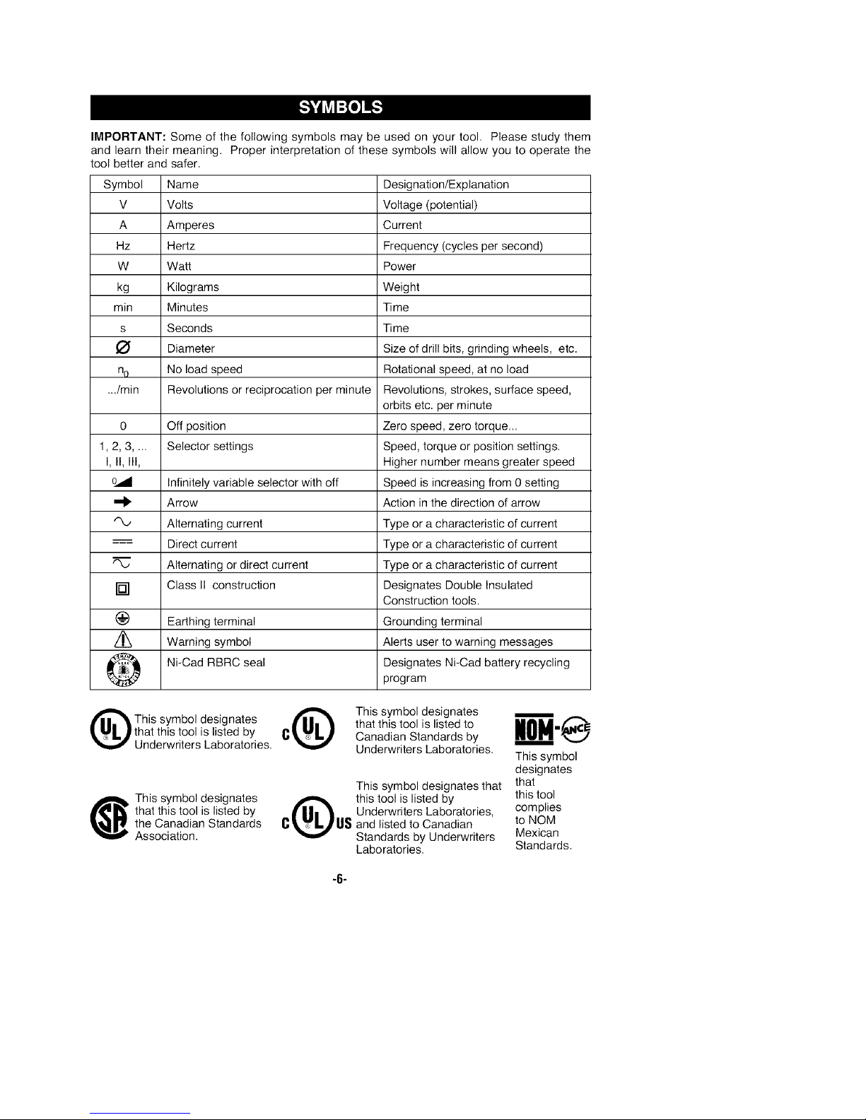
IMPORTANT: Some of the following symbols may be used on your tool. Please study them
and learn their meaning. Proper interpretation of these symbols will allow you to operate the
tool better and safer.
Symbol Name
V Volts
A Amperes
Hz Hertz
W Watt
kg Kilograms
min Minutes
s Seconds
Diameter
no No load speed
.../min Revolutions or reciprocation per minute Revolutions, strokes, surface speed,
0 Off position Zero speed, zero torque...
1, 2, 3.... Selector settings Speed, torque or position settings.
I, II, III, Higher number means greater speed
Infinitely variable selector with off Speed is increasing from 0 setting
Arrow Action in the direction of arrow
•"X., Alternating current Type or a characteristic of current
--_ Direct current Type or a characteristic of current
Alternating or direct current Type or a characteristic of current
[] Class II construction Designates Double Insulated
(_) Earthing terminal Grounding terminal
Warning symbol Alerts user to warning messages
Designation/Explanation
Voltage (potential)
Current
Frequency (cycles per second)
Power
Weight
Time
Time
Size of drill bits, grinding wheels, etc.
Rotational speed, at no load
orbits etc. per minute
Construction tools.
Ni-Cad RBRC seal Designates Ni-Cad battery recycling
This symbol designates
that this tool is listed by
Underwriters Laboratories.
that this tool is listed by
the Canadian Standards
This symbol designates
Association.
@ This symbol designates W
C Canadian Standards by
Q this tool is listed by
U_ and listed to Canadian
program
that this tool is listed to •
Underwriters Laboratories.
This symbol designates that
Underwriters Laboratories,
Standards by Underwriters
Laboratories.
-6-
This symbol
designates
that
this tool
complies
to NOM
Mexican
Standards.
Ir'_WLV,_l:t;tflR[_
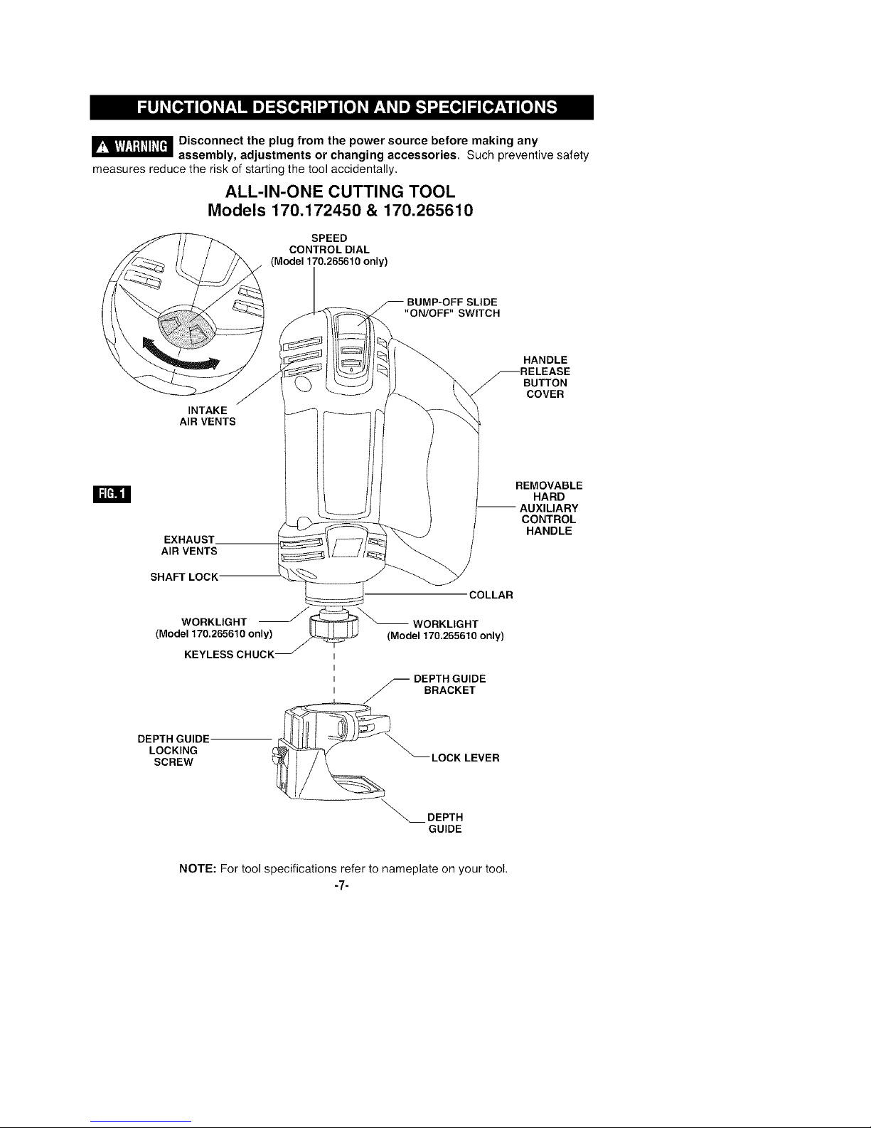
measures reduce the risk of starting the tool accidentally,
Disconnect the plug from the power source before making any
assembly, adjustments or changing accessories, Such preventive safety
ALL-IN-ONE CUTTING TOOL
Models 170.172450 & 170.265610
SPEED
CONTROL DIAL
(Model 170.265610 only)
INTAKE
AIR VENTS
W
EXHAUST.
AIR VENTS
BUMP-OFF SLIDE
"ON/OFF" SWITCH
HANDLE
BUTTON
COVER
REMOVABLE
HARD
JXILIARY
CONTROL
HANDLE
SHAFT LOCK
WORKLIGHT WORKLIGHT
(Model 170.265610 only) (Model 170.265610 only)
KEYLESS CHUCK t
t
t DEPTH GUIDE
t _ BRACKET
J
LOCKING _ LOCK LEVER
SCREW
DEPTH GUIDE -__".
DEPTH
GUIDE
NOTE: For tool specifications refer to nameplate on your tool.
"7"
COLLAR
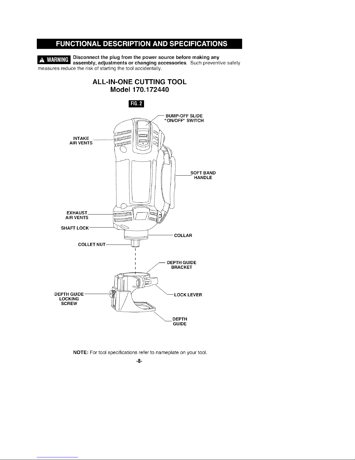
_ Disconnect the plug from the power source before making any
measures reduce the risk of starting the tool accidentally.
assembly, adjustments or changing accessories. Such preventive safety
ALL-IN-ONE CUTTING TOOL
Model 170.172440
W
BUMP-OFF SLIDE
"ON/OFF" SWITCH
INTAKE __
AIR VENTS
SOFTBAND
HANDLE
EXHAUST.
AIR VENTS
SHAFT LOCK
COLLAR
COLLETNUT
I
I
I
I _ DEPTH GUIDE
I J BRACKET
DEPTH GUIDE
LOCKING
SCREW
-_-LOCK LEVER
NOTE: For tool specifications refer to nameplate on your tool.
DEPTH
GUIDE
-8-

_ Disconnect the plug from
the power source before
making any assembly, adjustments or
changing accessories. Such preventive
safety measures reduce the risk of starting
the tool accidentally. Make certain that the
collet nut is securely tightened before turning
the tool on.
REMOVING AND INSTALLING THE
DEPTH GUIDE ASSEMBLY
The depth guide assembly consists of the
depth guide, locking screw and bracket.
In order to remove the depth guide from the
tool, release the locking lever and pull the
entire assembly straight off of the tool. To
reattach the assembly, fully replace the guide
onto the tool collar and lock the clamp lever
(Fig. 1).
INSTALLING BITS (Keyless models)
The bits are held by a keyless collet system
designed specifically for cut-out bits with 1/8"
(.125"), 1/4" (.250") or 5/32" (.156") shanks.
The bit flutes are sharp and
should be handled with
caution.
Depress and hold the shaft-lock in and rotate
the keyless chuck and shaft until the shaft-
lock engages and holds the shaft.
To prevent damage to tool.
Never use the shaft lock as a
braking devise to stop the tool from rotating.
Rotate the keyless chuck (counter-clockwise)
(Fig. 3). Remove the old bit (if there is one)
insert the new bit as far in as possible, but
not so far that the bit flutes engage the jaws
of the chuck (leave approximately 1/8" of
INSTALLING BITS (Standard models)
The bits are held by a collet system. Use either
the 1/8" (.125"), 1/4" (.250") or 5/32" (.156")
collet depending on the size of the bit shank.
Depress and hold the shaft-lock in and rotate
the collet nut and shaft until the shaft-lock
engages and holds the shaft.
Use the standard equipment wrench to
loosen nut (counter-clockwise) (Fig. 4).
Remove the old bit (if there is one) insert the
new bit as far in as possible, but not so far
that the bit flutes engage the collet (leave
approximately 1/8" of shank exposed)
Re-engage the shaft-lock and tighten the nut
(clockwise) by hand and then with the
wrench until bit is held securely.
shank exposed) Re-engage the shaft-lock
and securely tighten the keyless chuck
(clockwise) by hand.
Note: When using 1/4" & 5/32" bits it may be
necessary to use a wrench on the front of the
keyless chuck to securely tighten the bit.
Ir_ 1/8"--_.
SHAFT KEYLESS
LOCK CHUCK
II=[_lLq
SHAFT
LOCK
COLLET
NUT
-9-
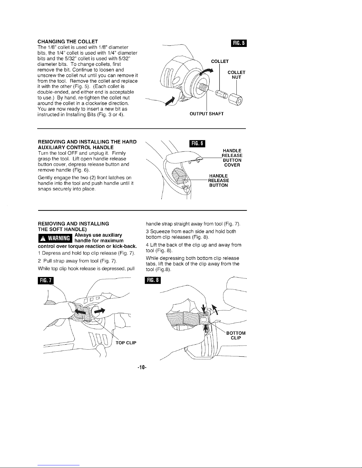
CHANGING THE COLLET
The 1/8" collet is used with 1/8" diameter
bits, the 1/4" collet is used with 1/4" diameter
bits and the 5/32" collet is used with 5/32"
diameter bits. To change collets, first
remove the bit. Continue to loosen and
unscrew the collet nut until you can remove it
from the tool. Remove the collet and replace
it with the other (Fig. 5). (Each collet is
double-ended, and either end is acceptable
to use.) By hand, re-tighten the collet nut
around the collet in a clockwise direction.
You are now ready to insert a new bit as
instructed in Installing Bits (Fig. 3 or 4).
COLLET
OUTPUT SHAFT
REMOVING AND INSTALLING THE HARD
AUXILIARY CONTROL HANDLE
Turn the tool OFF and unplug it. Firmly
grasp the tool. Lift open handle release
button cover, depress release button and
remove handle (Fig. 6).
Gently engage the two (2) front latches on
handle into the tool and push handle until it
snaps securely into place.
REMOVING AND INSTALLING
THE SOFT HANDLE)
_ Always use auxiliary
handle for maximum
control over torque reaction or kick-back.
1 Depress and hold top clip release (Fig, 7).
2 Pull strap away from tool (Fig, 7).
While top clip hook release is depressed, pull
\
\
handle strap straight away from tool (Fig. 7).
3 Squeeze from each side and hold both
bottom clip releases (Fig. 8).
4 Lift the back of the clip up and away from
tool (Fig. 8).
While depressing both bottom clip release
tabs, lift the back of the clip away from the
tool (Fig.8).
HANDLE
RELEASE
BUTTON
COVER
HANDLE
BUTTON
II1[_:!
IP
CLIP
-10-
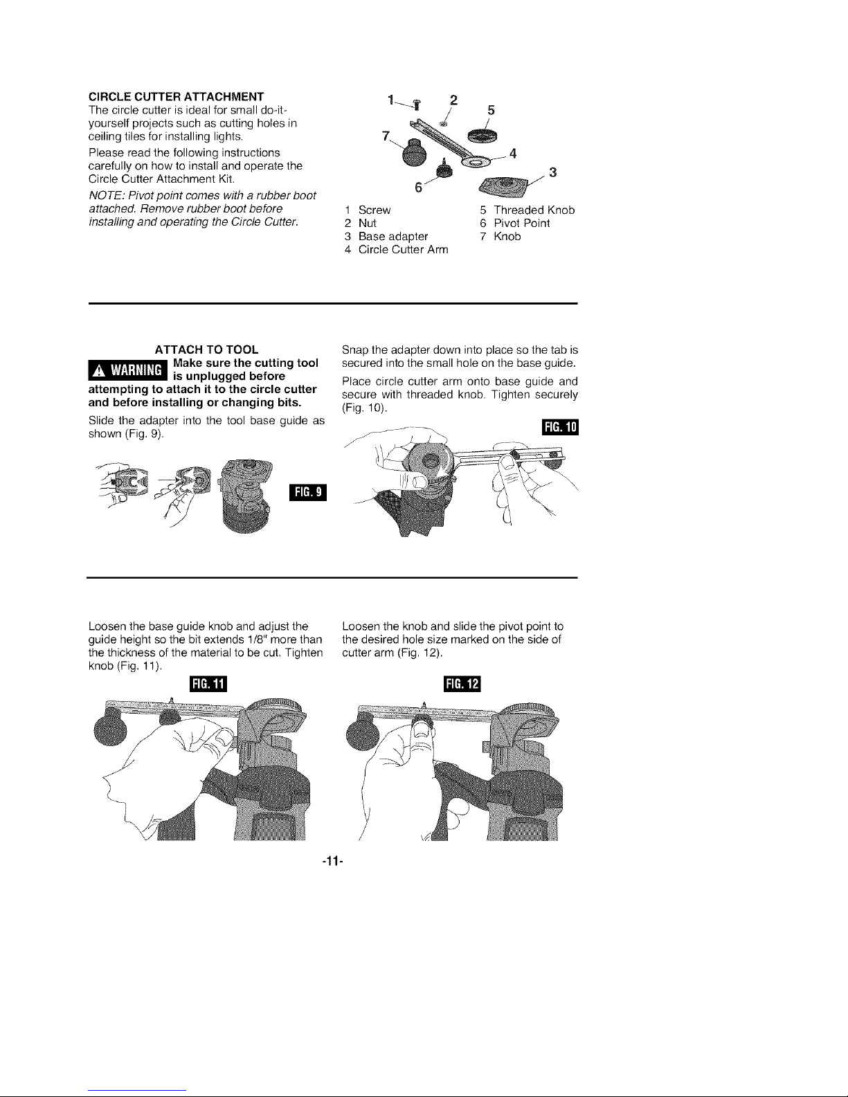
CIRCLE CUTTER ATTACHMENT
The circle cutter is ideal for small do-it-
yourself projects such as cutting holes in
ceiling tiles for installing lights,
Please read the following instructions
carefully on how to install and operate the
Circle Cutter Attachment Kit.
NOTE: Pivot point comes with a rubber boot
attached. Remove rubber boot before
installing and operating the Circle Cutter.
1 Screw 5 Threaded Knob
2 Nut 6 Pivot Point
3 Base adapter 7 Knob
4 Circle Cutter Arm
ATTACH TO TOOL
_Make sure the cutting tool
is unplugged before
attempting to attach it to the circle cutter
and before installing or changing bits.
Slide the adapter into the tool base guide as
shown (Fig. 9).
I1=[_]
Loosen the base guide knob and adjust the
guide height so the bit extends 1/8" more than
the thickness of the material to be cut, Tighten
knob (Fig, 11),
Snap the adapter down into place so the tab is
secured into the small hole on the base guide.
Place circle cutter arm onto base guide and
secure with threaded knob. Tighten securely
(Fig, 10),
Loosen the knob and slide the pivot point to
the desired hole size marked on the side of
cutter arm (Fig. 12).
-11-
 Loading...