

Page 1
Owner's Manual
lC.. TSM
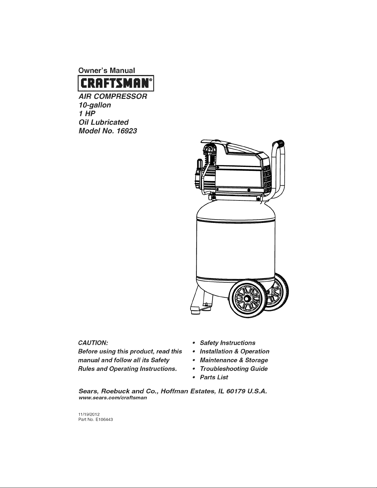
AiR COMPRESSOR
l O-gallon
1 HP
Off Lubricated
Model No. 16923
CAUTION:
Before using this product, read this
manual and follow all its Safety
Rules and Operating Instructions.
Sears, Roebuck and Co., Hoffman Estates, IL 60179 U.S.A.
www.sears.com/craftsman
11/19/2012
Part No E106443
, Safety Instructions
, installation & Operation
, Maintenance & Storage
° Troubleshooting Guide
, Parts List
Page 2
TABLE OF CONTENTS
Page
Warranty ................................................................ see below
Safety Symbols ................................................................... 1
important Safety Instructions & Guidelines .............................................. 1
Specifications .................................................................... 2
Glossary ........................................................................ 2
Duty Cycle ....................................................................... 2
Parts & Features .................................................................. 3
installation & Assembly ............................................................. 4
Operating Procedures .............................................................. 6
Maintenance ..................................................................... 7
Storage ......................................................................... 7
Troubleshooting Guide ............................................................. 8
Exploded View ................................................................... 9
Parts List ...................................................................... 10
Service Number ........................................................... back cover
CRAFTSMAN ONE YEAR FULL WARRANTY
FOR ONE YEAR from the date of purchase, this product is warranted against any defects in material
or workmanship. A defective product will receive free repair or replacement if repair is unavailable.
For warranty coverage details to receive free repair or replacement, visit the web site: www.craftsman.com
This warranty is void if this product is ever used while providing commercial services or if rented to
another person.
This warranty gives you specific legal rights, and you may also have other rights which vary from state
to state.
Sears Brands Management Corporation, Hoffman Estates, IL 60179 U.S.A.
Page 3
Safety Instructions
The information listed below should be read and
understood by the operator. This information is
given to protect the user while operating and stor-
ing the air compressor. We utilize the symbols
below to allow the reader to recognize important
information about their safety.
Indicates an imminently hazardous situation
which, if not avoided, will result in death or seri-
ous injury.
Indicates a potentially hazardous situation
which, if not avoided, could result in death or
serious injury.
Indicates a potentially hazardous situation
which, if not avoided, may result in minor or
moderate injury.
When used without the safety alert symbol indi-
cates a potentially hazardous situation which, if
not avoided, may result in property damage.
Important Safety Instructions and Guidelines
* Save all instructions
Improper operation or maintenance of this product could result in serious injury and/or property
damage. Read and understand all of the warnings and safety instructions provided before using this
equipment.
The air compressor should be operated on a dedicated 15 amp circuit. If
the circuit does not have 15 free amps available, a larger circuit must be
used. Always use more air hose before utilizing extension cords. All exten-
sion cords used must be 12 gauge with a maximum length of 25 ft. The
circuit fuse type must be a time delay. Low voltage could cause damage to
the motor.
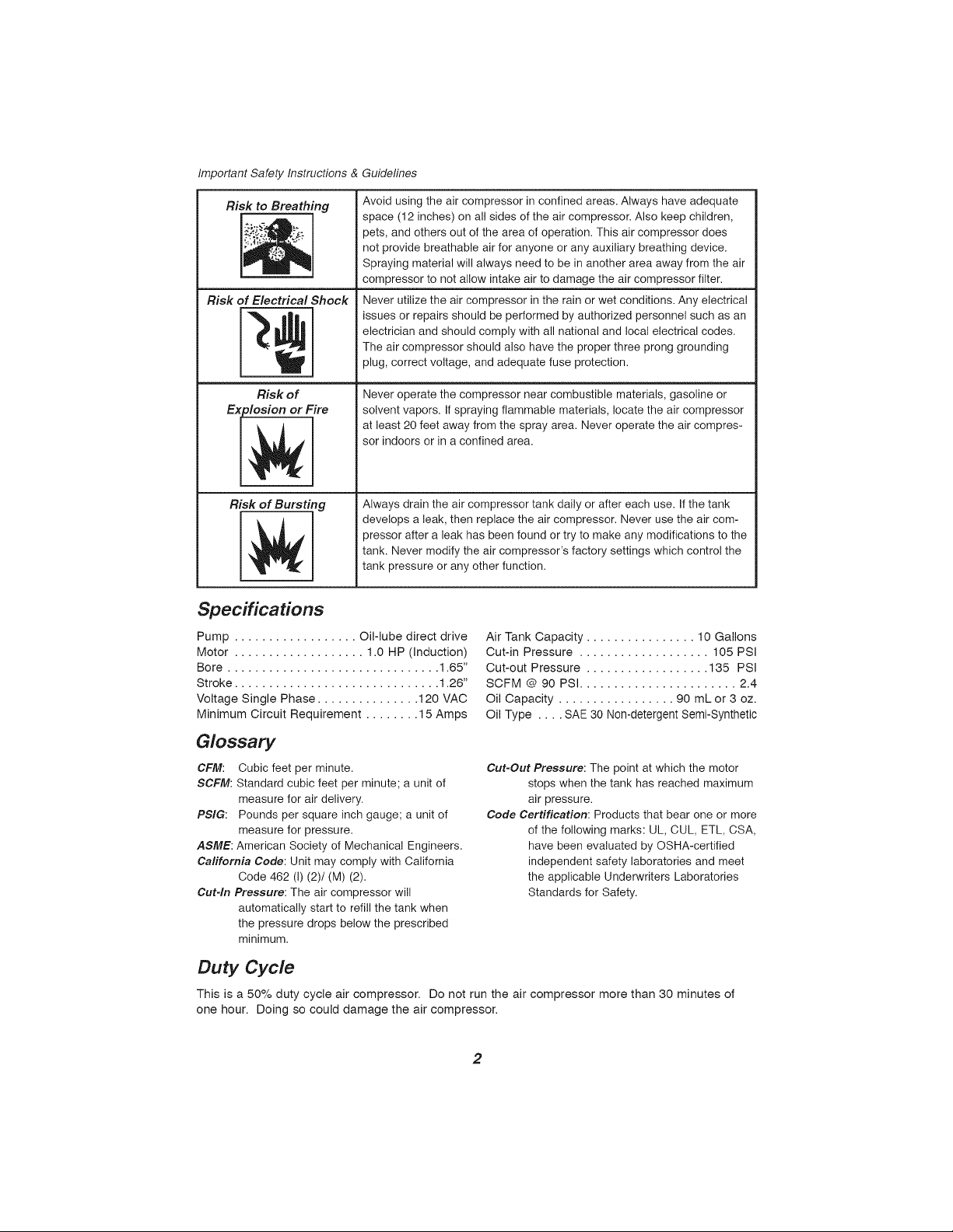
Risk of Moving Parts
Risk of Burns
If the air compressor is in operation, all guards and covers should be
attached or installed correctly. If any guard or cover has been damaged,
do not operate the equipment until the proper personnel has correctly re-
paired the equipment. The power cord should be free of any moving parts,
twisting and/or crimping while in use and while in storage.
There are surfaces on your air compressor that while in operation and
thereafter can cause serious burns if touched. The equipment should be
allowed time to cool before any maintenance is attempted. Items such as
the compressor pump and the outlet tube are normally hot during and after
operation.
Risk of Falling
Risk from Fl_Objects
Operation of the air compressor should always be in a position that is
stable. Never use the air compressor on a rooftop or elevated position that
could allow the unit to fall or be tipped over. Use additional air hose for
elevated jobs.
Always wear ANSI Z87.1 approved safety glasses with side shields when
the air compressor is in use. Turn off the air compressor and drain the air
tank before performing any type of maintenance or disassembly of the
hoses or fittings. Never point any nozzle or sprayer toward any part of the
body or at other people or animals.
Page 4
Important Safety Instructions & Guidelines
Risk to Breathing
Risk of Electrical Shock
Risk of
Explosion or Fire
Risk of Bursting
Avoid using the air compressor in confined areas. Always have adequate
space (12 inches) on all sides of the air compressor. Also keep children,
pets, and others out of the area of operation. This air compressor does
not provide breathable air for anyone or any auxiliary breathing device.
Spraying material will always need to be in another area away from the air
compressor to not allow intake air to damage the air compressor filter.
Never utilize the air compressor in the rain or wet conditions. Any electrical
issues or repairs should be performed by authorized personnel such as an
electrician and should comply with all national and local electrical codes.
The air compressor should also have the proper three prong grounding
plug, correct voltage, and adequate fuse protection.
Never operate the compressor near combustible materials, gasoline or
solvent vapors. If spraying flammable materials, locate the air compressor
at least 20 feet away from the spray area. Never operate the air compres-
sor indoors or in a confined area.
Always drain the air compressor tank daily or after each use. If the tank
develops a leak, then replace the air compressor. Never use the air com-
pressor after a leak has been found or try to make any modifications to the
tank. Never modify the air compressor's factory settings which control the
tank pressure or any other function.
Specifications
Pump .................. Oil-lube direct drive
Motor ................... 1.0 HP (Induction)
Bore ............................... 1.65"
Stroke .............................. 1.26"
Voltage Single Phase ............... 120 VAC
Minimum Circuit Requirement ........ 15 Amps
Air Tank Capacity ................ 10 Gallons
Cut-in Pressure ................... 105 PSI
Cut-out Pressure .................. 135 PSI
SCFM @ 90 PSI ....................... 2.4
Oil Capacity ................. 90 mL or 3 oz.
Oil Type .... SAE 30 Non-detergent Semi-Synthetic
Glossary
CFM: Cubic feet per minute.
SCFM: Standard cubic feet per minute; a unit of
measure for air delivery,
PSIG: Pounds per square inch gauge; a unit of
measure for pressure.
ASME: American Society of Mechanical Engineers,
Cafifornia Code: Unit may comply with California
Code 462 (I) (2)/(M) (2).
Cut-In Pressure: The air compressor will
automatically start to refill the tank when
the pressure drops below the prescribed
minimum.
Cut-Out Pressure: The point at which the motor
stops when the tank has reached maximum
air pressure.
Code Certification: Products that bear one or more
of the following marks: UL, CUL, ETL, CSA,
have been evaluated by OSHA-certified
independent safety laboratories and meet
the applicable Underwriters Laboratories
Standards for Safety.
Duty Cycle
This is a 50% duty cycle air compressor. Do not run the air compressor more than 30 minutes of
one hour. Doing so could damage the air compressor.
2
Page 5
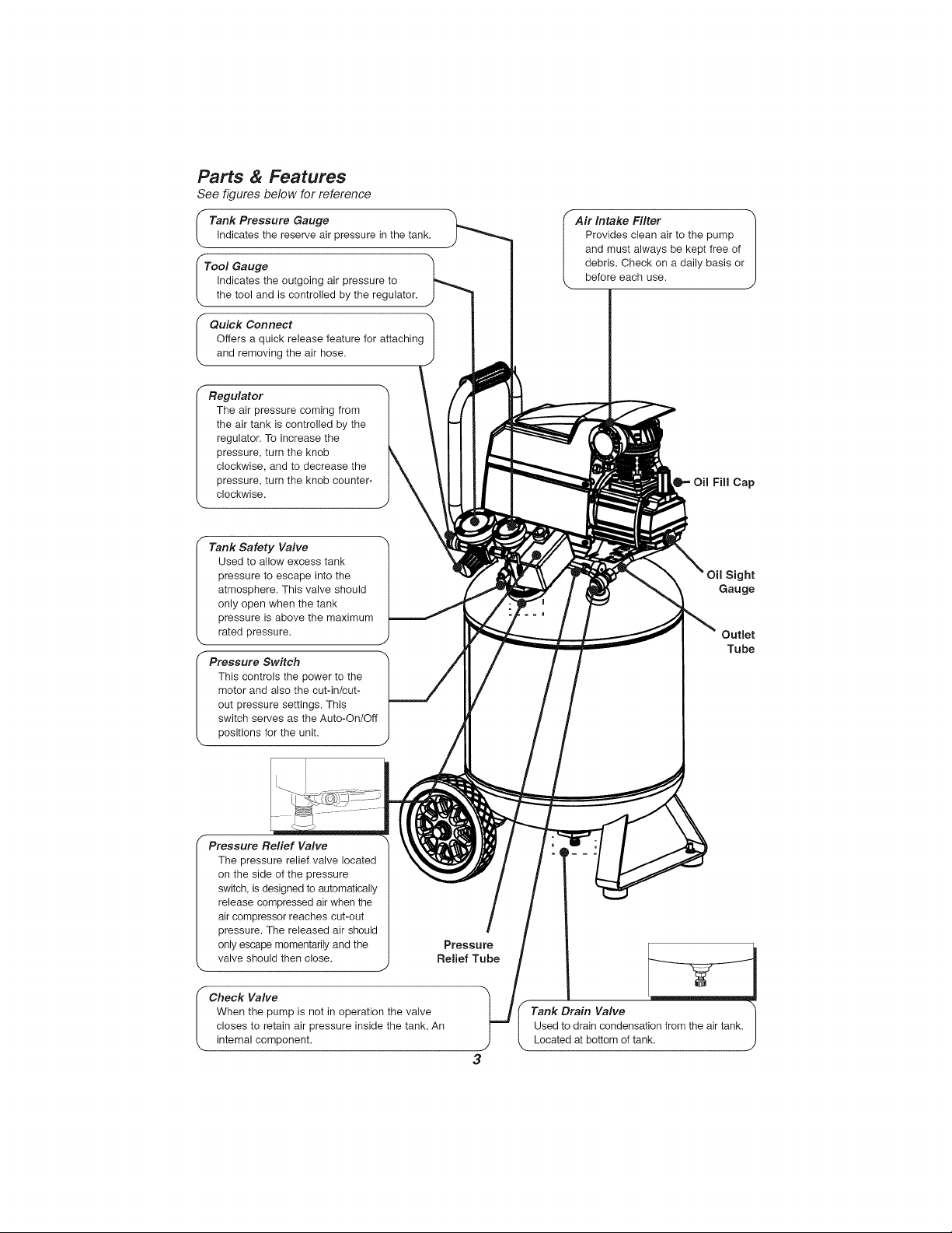
Parts & Features
See figures below for reference
I Tank Pressure Gauge
Indicates the reserve air pressure in the tank.
Indicates the outgoing air pressure to
the tool and is controlled by the regulator.
Offers a quick release feature for attaching
I Quick Connect -1
and removing the air hose.
The air pressure coming from
the air tank is controlled by the
regulator. To increase the
pressure, turn the knob
clockwise, and to decrease the
pressure, turn the knob counter-
clockwise.
Used to allow excess tank
pressure to escape into the
atmosphere. This valve should
only open when the tank
I Tank Safety Valve
pressure is above the maximum
rated pressure.
f Air Intake Filter
Provides clean air to the pump
and must always be kept free of
debris. Check on a daily basis or
before each use.
Oil Fill Cap
Sight
Gauge
Outlet
Tube
This controls the power to the
motor and also the cut-in/cut-
out pressure settings. This
I Pressure Switch
switch serves as the Auto-On/Off
positions for the unit.
Pressure Relief Valve
The pressure relief valve located
on the side of the pressure
switch, is designed to automatically
release compressed air when the
air compressor reaches cut=out
pressure. The released air should
only escape momentarily and the
valve should then close.
Check Valve
When the pump is not in operation the valve
closes to retain air pressure inside the tank. An
internal com
Preseute
Relief Tube
Tank Drain Valve
Used to drain condensation from the air tank.
Located at bottom of tank.
Page 6
installation & Assembly
The air compressor should be turned off, unplugged from the power source, the air bled from the
tank and the unit allowed time to cool before any maintenance is performed. Personal injuries could
occur from moving parts, electrical sources, compressed air or hot surfaces. The quick connect as-
sembly must be attached before use. Failure to assemble correctly could result in leaks and possible
injury. If unsure of assembly instructions or you experience difficulty in the assembly please call our
toll free number for assistance.
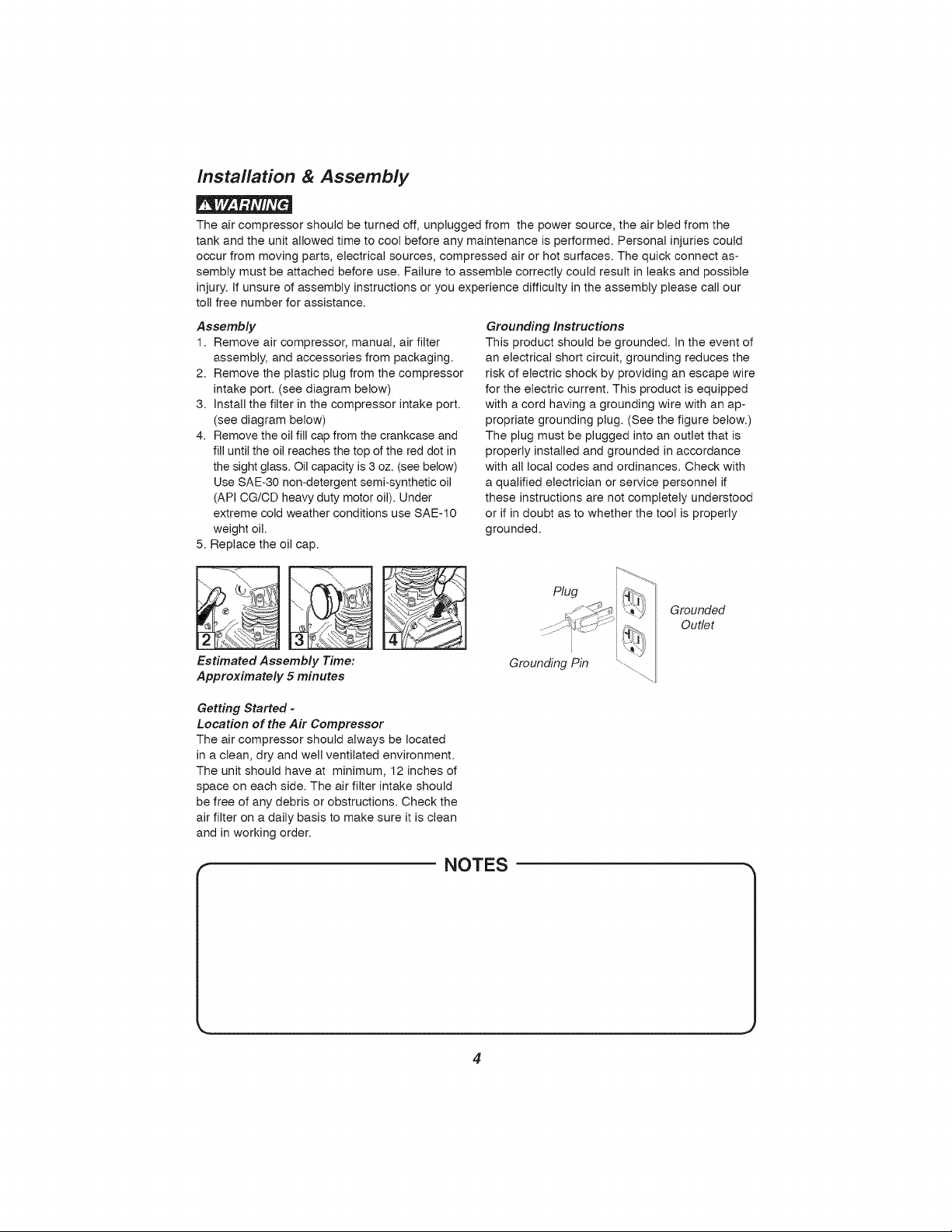
Assembly
1. Remove air compressor, manual, air filter
assembly, and accessories from packaging.
2. Remove the plastic plug from the compressor
intake port. (see diagram below)
3. Install the filter in the compressor intake port.
(see diagram below)
4. Remove the oil fill cap from the crankcase and
fill until the oil reaches the top of the red dot in
the sight glass. Oil capacity is 3 oz. (see below)
Use SAE-30 non-detergent semi-synthetic oil
(API CG/CD heavy duty motor oil). Under
extreme cold weather conditions use SAE-10
weight oil.
5. Replace the oil cap.
Grounding Instructions
This product should be grounded. In the event of
an electrical short circuit, grounding reduces the
risk of electric shock by providing an escape wire
for the electric current. This product is equipped
with a cord having a grounding wire with an ap-
propriate grounding plug. (See the figure below.)
The plug must be plugged into an outlet that is
properly installed and grounded in accordance
with all local codes and ordinances. Check with
a qualified electrician or service personnel if
these instructions are not completely understood
or if in doubt as to whether the tool is properly
grounded.
Plug
Grounded
..... Outlet
Estimated Assembly Time:
Approximately 5 minutes
Getting Started -
Location of the Air Compressor
The air compressor should always be located
in a clean, dry and well ventilated environment.
The unit should have at minimum, 12 inches of
space on each side. The air filter intake should
be free of any debris or obstructions. Check the
air filter on a daily basis to make sure it is clean
and in working order.
Grounding Pin
NOTES
4
Page 7
Installation & Assembly
Improper installation of the grounding plug will result in a risk of electric shock. If repair or replace-
ment of the cord or plug is necessary, do not connect the grounding wire to either flat blade terminal.
The wire with insulation having an outer surface that is green with or without yellow stripes is the
grounding wire. Check with a qualified electrician or serviceman if the grounding instructions are not
completely understood, or if in doubt as to whether the product is properly grounded. Do not modify
the plug provided; if it will not fit the outlet, have the proper outlet installed by a qualified electrician.
This product is for use on a circuit having a nominal rating of 120 volts and is factory-equipped with
a specific electric cord and plug to permit connection to a proper electric circuit. Make sure that the
product is connected to an outlet having the same configuration as the plug. No adapter should be
used with this product. If the product must be reconnected for use on a different type of electric circuit,
qualified service personnel should make the reconnection.
Extension Cords
Use only a 3-wire extension cord that has a 3-blade grounding plug, and a 3-slot receptacle that will
accept the plug on the product. Make sure your extension cord is in good condition. When using an
extension cord, be sure to use one heavy enough to carry the current your product will draw. Cords
must not exceed 25 feet and No. 12 AWG size must be used. An undersized cord will cause a drop in
line voltage resulting in loss of power and overheating.
Break In Procedures
No break in procedure is required by the user. This product is factory tested to ensure proper opera-
tion and performance.
NOTES
J
5
Page 8
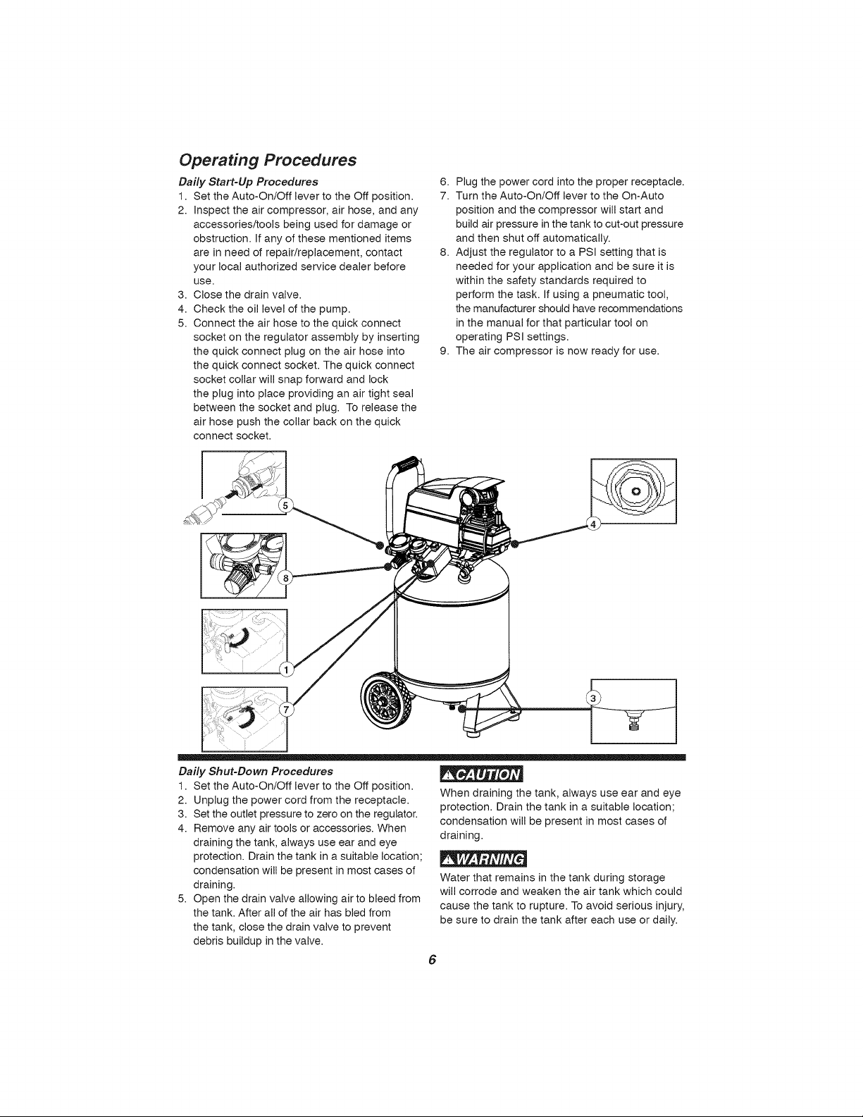
Operating Procedures
Daily Start-Up Procedures
1. Set the Auto-On/Off lever to the Off position.
2. Inspect the air compressor, air hose, and any
accessories/tools being used for damage or
obstruction. If any of these mentioned items
are in need of repair/replacement, contact
your local authorized service dealer before
use.
3. Close the drain valve.
4. Check the oil level of the pump.
5. Connect the air hose to the quick connect
socket on the regulator assembly by inserting
the quick connect plug on the air hose into
the quick connect socket. The quick connect
socket collar will snap forward and lock
the plug into place providing an air tight seal
between the socket and plug. To release the
air hose push the collar back on the quick
connect socket.
i
6. Plug the power cord into the proper receptacle.
7. Turn the Auto-On/Off lever to the On-Auto
position and the compressor will start and
build air pressure in the tank to cut-out pressure
and then shut off automatically.
8. Adjust the regulator to a PSI setting that is
needed for your application and be sure it is
within the safety standards required to
perform the task. If using a pneumatic tool,
the manufacturer should have recommendations
in the manual for that particular tool on
operating PSI settings.
9. The air compressor is now ready for use.
Daily Shut-Down Procedures
1. Set the Auto-On/Off lever to the Off position.
2. Unplug the power cord from the receptacle.
3. Set the outlet pressure to zero on the regulator.
4. Remove any air tools or accessories. When
draining the tank, always use ear and eye
protection. Drain the tank in a suitable location;
condensation will be present in most cases of
draining.
5. Open the drain valve allowing air to bleed from
the tank. After all of the air has bled from
the tank, close the drain valve to prevent
debris buildup in the valve.
When draining the tank, always use ear and eye
protection. Drain the tank in a suitable location;
condensation will be present in most cases of
draining.
Water that remains in the tank during storage
will corrode and weaken the air tank which could
cause the tank to rupture. To avoid serious injury,
be sure to drain the tank Nter each use or daily.
6
Page 9
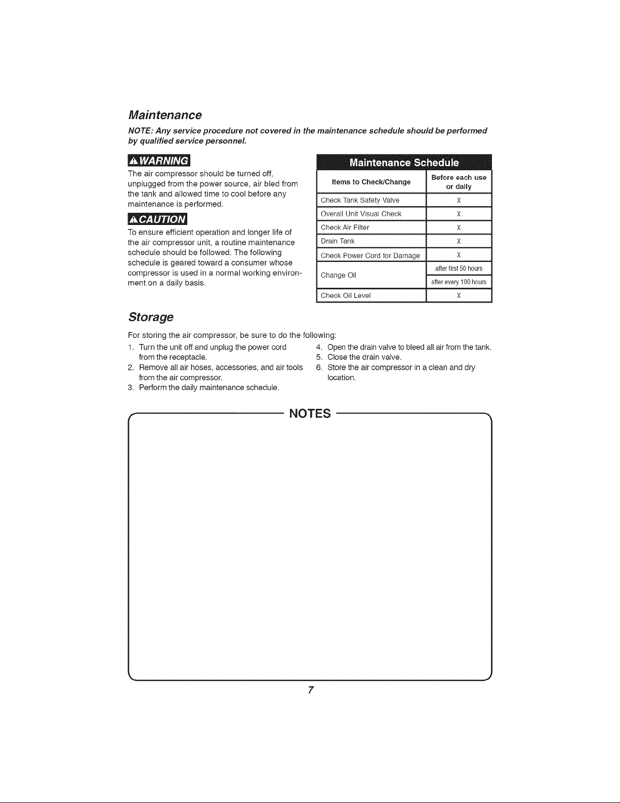
Maintenance
NOTE: Any service procedure not covered in the maintenance schedule should be performed
by qualified service personnel
The air compressor should be turned off,
unplugged from the power source, air bled from
the tank and allowed time to cool before any
maintenance is performed.
To ensure efficient operation and longer life of
the air compressor unit, a routine maintenance
schedule should be followed. The following
schedule is geared toward a consumer whose
compressor is used in a normal working environ-
ment on a daily basis.
Items to Check/Change
Check TankSafety Valve
Overall Unit Visual Check
Check Air Filter
DrainTank
Check PowerCord for Damage
Change Oil
Check 0il Level X
Before each use
or daily
X
X
X
X
X
afterfirst50hours
afterevery100hours
Storage
For storing the air compressor, be sure to do the following:
1. Turn the unit off and unplug the power cord 4. Open the drain valve to bleed all air from the tank.
from the receptacle. 5. Close the drain valve.
2. Remove all air hoses, accessories, and air tools 6. Store the air compressor in a clean and dry
from the air compressor, location.
3. Perform the daily maintenance schedule.
NOTES
7
Page 10

Troubleshooting Guide
The air compressor should be turned off and unplugged from the power source before any mainte-
nance is performed as well as the air bled from the tank and the unit allowed time to cool. Personal
injuries could occur from moving parts, electrical sources, compressed air, or hot surfaces.
PROBLEM POSSIBLE CORRECTION
Air leaks at the check A defective check valve results in a constant air leak at the pressure relief
valve or at the pres- valve when there is pressure in the tank and the compressor is shut off.
sure relief valve. Drain the tank, then remove and clean or replace the check valve.
Air leaks between Be sure of proper torque on head bolts, if leak remains, contact a service
head and cylinder, technician.
Air leak from safety Operate the safety valve manually by pulling on the ring. If the valve con-
valve, tinues to leak when in the closed position, it should be replaced.
Pressure reading on If there is an excessive amount of pressure drop when the accessory is
the regulated pressure used, replace the regulator.
gauge drops when an
accessory is used. NOTE:
Adjust the regulated pressure under flow conditions (while accessory is
being used). It is normal for the gauge to show minimal pressure loss
during initial use of the tool.
Excessive tank pres- Move the Auto-On/Off lever to the Off position. If the unit doesn't shut off,
sure. unplug it from the power source and contact a service technician.
Motor will not start. Make sure power cord is plugged in and the switch is on. Inspect for the
Excessive moisture in Remove the water in the tank by draining after each use. High humidity
the discharge air. environments will cause excessive condensation. Utilize water filters on
proper size fuse in your circuit box. If the fuse was tripped, reset it and
restart the unit. If repeated tripping occurs, replace the check valve or
contact a service technician.
your air line.
NOTE:
Water condensation is not caused by compressor malfunction. Be sure
the compressor's air output is greater than your tool's air consumption
rate.
Air leaks from the tank Never drill into, weld or otherwise modify the air tank or it will weaken.
body or tank welds. The tank can rupture or explode. Compressor cannot be repaired. Dis-
continue use of the air compressor.
Page 11

Craftsman Air Compressor Model 16923
Exploded View
3-- 2 __"_
/
65 --\
\
\
........ 39
Page 12

Craftsman Air Compressor Model 16923
Parts List
Ref. Kit Part Ref. Kit Part
# # Number Description Qty # # Number Description Qty
1 3 Screw, M6 X 1.0ram 4 25 3 E100248 Capacitor, Starting 1
2 3 Washer, Lock M6 8 8ram
3 3 E100227 Head, Cylinder 1 27 3 Nut, M8x1.25, ZDC 6
4 1 & 3 Gasket, Head to Valve 1
5 3 E100228 Plate, Valve 2 29 N/A
6 3 E100229 Valve Reed 2 30 3 Assembly, Motor/Pump, 1
7 1 & 3 Gasket, Valve Plate 1
8 1 & 3 Gasket, Cylinder to 1
9 2&3 E101113 Cylinder 1
10 3 Screw, SHC M6 x 1.0 4 33 6 Nut, Comp, 3/8" 2
11 1 & 3 Gasket, Cylinder, 1
12 2 & 3 Eccentric for L1 1 36 5 Ferrule, 1/4" 2
13 2 & 3 Nut, Hex, M6x1.0 3 37 5 Nut, Comp, 1/4" 2
14 2 & 3 Screw, SHC M6 x 1.0 1 38 5 Tube, Relief 1/4" 1
18 2&3 L1 Piston/Connecting 1 39 Tank/Frame Assy, 10 1
16 1 & 3 Bafflefor L1 1 40 Washer, Flat M6 2
17 3 E100087 Cap, Oil Fillw/o-ring 1 41 E101037 Isolator, Rubber 2
18 3 E100566 Cover, Crankcase 1 42 Screw, SHC, M6 x 1.0 2
19 3 E100078 Plug, oil sightw/seal 1 43 E100098 Valve, Drain Multi-Turn 1
20 3 Screw, HFH M5 x 0.8 4 44 7 Nut, Hex MlOx1.28 2
21 3 Motor Assembly/Pump 1
22 3 E100860 Fan, Motor F1 125mm 1 M10x1.25x45rnrn
23 3 Ring,Snap,Outer, 15mm 1 48 E101340 Cord, Power16/3 AWG 1
24 3 E100247 Capacitor,Running 1
X 30ram
Plate 28 N/A
Valve Plate
x 20MM 34 6 Tube, Outlet 3/8" 1
Lower 38 E101362 Valve, Check LH 1
x 20MM Aluminum
RodAssembly Gallon, L110VWS
for L1 x 25mm
x 18MM (Yellow Zinc
Dich Plate) 48 7 Washer, Flat MIO 2
Housing, L1B2
26 3 Washer, Tooth Lock, 2
6.5MM TALL
L1B2w/RHExhaust
31 E100809 Fitting, EIbow,3/8NPT 1
x 3/8 Comp
32 6 Ferrule, 3/8" 2
Aluminum Finned
46 7 Wheel, Black Hub 2
47 7 Bolt, Shoulder, 2
type ST 6' long
i NOTES 1
10
Page 13

Craftsman Air Compressor Model 16923
Parts List
Ref. Kit Pert
# # Number Description Qty
49 E100853 Nipple, 1/4"NPT X 1
50 E102611 Valve, Safety 1
51 E102857 Nipple, 1/4"NPT X 1
52 E100059 Regulator, Square 1
53 E100307 Quick Connect, Brass 1
54 E103369 Gauge, Pressure, 1
55 E104074 Ring, BezelTool(50 1
56 E106477 Assy, Switch, Pressure 1
57 E103363 Gauge, Pressure, 1
58 E104568 Ring, BezelTank(38 1
59 Screw, Hex Flange 4
60 E101335 Handle 1
61 E105883 Grip, Rubber 1
62 4 Cover, Filter 1
63 4 E100435 Element, Intake Filter 1
35MM
43MM
Body LHFlow
(50mm 135 PSI R/L,
1/4' NPT)
mm)
(135 PSI)
(38mm w/135 PSI R/L)
mm)
Head, MSX0.8X15mm
Note: Any part/kit number field without a number is not avail-
able. Descriptions are provided for reference only. The Kit #
column represents that the part being offered is available in a
kit. One of each part per kit will be offered.
Kit numberand parts that are included are as follows:
Kit No. Part No. Description No.
1 E100959 Kit,GasketRebuild 4,7,8,11,16
2 E100251 Kit, Piston- (Note:Order 9,12thru15
3 E105154 Kit, L1B2 Motor/Pump 1- 27,30
4 E100794 Kit, Air Filter 62-64
5 E105953 Kit, 1/4"CuPressure 36-38
6 E105952 Kit, 3/8" AluminumOutlet 32-34
7 E102192 Kit, Wheel (this kit isfor 44-47
GasketKit#1,aswell,
when orderingthis kit)
Assy. w/RH Exhaust
ReliefTube
Tube
onewheelonly)
Reference
NOTES
64 4 Base, Air Filter 1
65 Screw, Hex Flange 6
Head, MSX0.8Xl0mm
66 E105615 Shroud 1
67 Bolt, SHCM8x 1.25 x 4
25mm (ZDC Plate)
68 Washer, Lock, M8 4
69 Washer, Flat M8 4
70 E101802 Strain Relief, 16/3 1
AWG ST
11
Page 14

Manual de
i
COMPRESOR DE AIRE
37.9 iitros
1 HP
Lubricada con aceite
# de Modelo 16923
PRECAUCION:
Antes de usar el producto, lea este
manual y siga sus reglas e instruc-
clones de seguridad.
Sears, Roebuck and Co., Hoffman Estates, IL 60179 U.S.A.
www.sears.com/craftsman
11/19/2012
Part No. E106443
* Instrucciones y pautas de
seguridad importantes
* Instalaci6n y ensamblaje
* Procedimientos de operaci6n
* MantenimientoyAImacenamiento
* Diagn6stico y correcci6n de fa#as
* Lista de las piezas
Page 15

CONTENIDO
P&gina
Garanfia ................................................................ esta p&gina
Simbolos de seguridad ............................................................ 15
Instrucciones y pautas de seguridad importantes ........................................ 15
Especificaciones ................................................................. 16
GIosario ........................................................................ 16
Ciclo de trabajo .................................................................. 16
Partes y caracteristicas ............................................................ 17
Instalaci6n y ensamblaje ........................................................... 18
Procedimientos de operaci6n ....................................................... 20
Mantenimiento ................................................................... 21
AImacenamiento ................................................................. 22
Diagn6stico y correcci6n de fallas .................................................... 22
Vista esquem_.tica ............................................................... 23
Lista de las piezas ............................................................... 24
NOmero de servicio ........................................................ Contratapa
UN AKIO DE GARANTiA DE CRAFTSMAN
DURANTE UN AIqO desde la fecha de compra, este producto tiene garantia contra defectos en los
materiales o en la fabricaci6n. Los productos defectuosos se reparar_.n gratuitamente o se reempla-
zar&n sin coste si la reparaci6n no es possible.
Para conocer los detalles de cobertura de la garanfia con el fin de obtener una reparaci6n o un reem-
plazo, visite el sitio web www.craftsman.com
Esta garanfia no es v_.lida si el producto se utiliza para proporcionar servicios comerciales o si se
alquila a un tercero.
Esta garanfia le proporciona derechos legales especificos yes posible que adem&s tenga otros
derechos, dependiendo del pais o el estado.
Sears Brands Management Corporation, Hoffman Estates, IL 60179 EE. UU.
Page 16

Instrucciones de seguridad
El operador debe leer y entender la informaci6n si-
guiente. Esta informaci6n se ofrece para proteger
al usuario durante la operaci6n y el almacenaje
del compresor. Los simbolos siguientes son los
que se utilizan para indicar al lector informaciOn
que es importante para su seguridad.
Indica una situaci6n de riesgo inminente que,
de no evitarse, provocaria lesiones graves o la
muerte.
Indica una situaciOn potencialmente peligrosa
que, de no evitarse, podria provocar lesiones
graves o la muerte.
Indica una situaci6n potencialmente peligrosa
que, de no evitarse, podria provocar lesiones
menores o moderadas.
AI aparecer sin el simbolo de alerta de se-
guridad, indica una situaciOn potencialmente
peligrosa que, de no evitarse, podria causar
dafios materiales.
Instrucciones y pautas de seguridad importantes
* Guarde todas las instrucciones
La operaciOn y el mantenimiento inadecuados de este producto pueden provocar lesiones graves y
dafios materiales. Antes de utilizar este equipo, lea y entienda las advertencias e instrucciones de
seguridad aqui contenidas.
El compresor de aire se debe operar desde un circuito dedicado de 15
amperes. Si el circuito no dispone de una capacidad de 15 amperes,
se debe usar un circuito de mayor capacidad. Si es necesario, antes de
emplear una extension electrica, aflada una manguera de aire mas larga.
Las extensiones electricas deben ser de calibre 12 y tener una Iongitud
maxima de 7.6 metros. El fusible del circuito debe ser de acci6n
retardada. Un voltaje demasiado bajo puede dafiar el motor.
Riesgo por partes en
movimiento
Antes de operar el compresor, todos los protectores y cubiertas deben
estar instalados correctamente. Si alguno de los protectores o cubiertas
esta dafiado, no opere el equipo sino hasta que personal calificado repare
el problema. El cable de corriente se debe mantener alejado de las partes
moviles del equipo y no debe torcerse ni prensarse durante su empleo ni
al ser almacenado.
Ries_ o de guemaduras
Rico de caida
Riesgo de lanzamiento
de objetos
En su compresor hay superficies que, de ser tocadas durante y despues
de su operaci6n, pueden causar quemaduras graves. Antes de darle
mantenimiento al equipo, se ledebe dejar enfriar. Por Io normal, durante y
despues de su operaci6n, ciertas partes como la bomba del compresor y
el tubo de salida estaran calientes.
El compresor siempre se debe operar en una posici6n estable. Nunca
utilice el compresor sobre un techo o en una posici6n elevada desde
donde podr[a caer o volcarse. AI trabajar en posiciones elevadas, utilice
una manguera de aire mas larga.
AI emplear el compresor, siempre utilice anteojos de seguridad con
protectores laterales que cumplan con la norma ANSI Z87.1. Antes de
Ilevar a cabo cualquier clase de mantenimiento y antes de desconectar las
mangueras y acopladores, apague el compresor y drene el tanque de aire.
Nunca apunte la boquilla o rociador hacia ninguna parte de su cuerpo ni
del de otros seres.
15
Page 17

Instrucciones y pautas de seguridad importantes
Riesgo para la
res_iraci6n
Riesgo de descargas
el_ctricas
Riesgo de explosi&n
Rie_llido
Evite utilizar el compresor de aire en areas encerradas. Siempre tenga
un espacio libre adecuado (30 cm.) en todos los lados del compresor.
Tambien mantenga fuera del area de operaci6n a mascotas, niflos y otras
personas. Este compresor de aire no provee aire que pueda ser respirado
ni empleado con un dispositivo respiratorio auxiliar. El material de rociado
siempre debera estar en otra zona, alejado del compresor de aire, para
evitar que el aire aspirado dafle el filtro del compresor.
Nunca utilice el compresor de aire bajo Iluvia o en lugares mojados. Los
problemas electricos deben ser reparados por personal autorizado, tal
como seria un electricista, y deben cumplir con las normas el6ctricas
nacionales y locales. El compresor tambien debe tener la clavija apropiada
de tres terminales y contar con un suministro el6ctrico que sea del voltaje
correcto y con un fusible de protecci6n adecuado.
Nunca opere el compresor cerca de materiales combustibles, gasolina ni
vapores de solventes. Si est& rociando materiales inflamables, coloque el
compresor a una distancia de cuando menos 6 metros del &rea de rocia-
do. Nunca opere el compresor de aire en interiores o en lugares cerrados.
Drene el compresor diariamente o despues de cada utilizaci6n. Si el
tanque tiene una fuga, reemplace el compresor. No utilice el compresor si
se ha detectado una fuga, nitrate de modificar el tanque. Nunca modifique
los ajustes de fabrica del compresor que controlan la presi6n del tanque y
demas funciones.
Especificaciones
Bomba ...................... De impulsJ6n
................ directa, lubricada con aceite
Motor ................... 1.0 HP (Inducci6n)
Di&metro .......................... 42 mm
Carrera ........................... 32 mm
Voltaje monof&sJco ................. 120 VAC
Glosario
CFM: Pies cQbicos por minuto.
SCFM: Pies cQbicos est&ndar por minuto; unidad
de medici6n de suministro de aire.
PSIG: Libras por pulgada cuadrada sobre la
presi6n atmosf@ica; unidad de medici6n de
presi6n.
ASME: Sociedad estadounidense de ingenieros
mecanicos.
Cddigo de California: La unidad puede cumplir
con el c6digo de Oalifornia 462 (I) (2)/(M) (2).
Capacidad de tanque de aire ... 37,8 litros / 10
galones US
PresJ6n de conexJ6n ............... 105 PSI
PresJ6n de desconexi6n ............ 135 PSI
Presi6n de parada ....... 861.8 KPa / 125 PSI
Pies cQbJcos por mJnuto (SCFM) a 90 LPPC. 2.4
Capacidad del aceite ........ 90 ml o 3 onzas.
Tipo de aceite .................. SAE 30 / no
detergente - semi-sintetico
Presidn de arranque: El compresor arranca
automaticamente cuando la presi6n baja a menos
del minimo prescrito.
Presion de parada: Presi6n de aire que tiene que
alcanzarse en el tanque para que se detenga el
motor.
CertificaciSn de codigo: Los productos que tienen
alguna o varias de las siguientes marcas han sido
evaluados por laboratorios de seguridad indepen-
dientes certificados por OSHA, y cumplen con las
normas de seguridad de Underwriters Laboratories:
UL, CUL, ETL, CSA.
Ciclo de trabajo
Este compresor tiene un cJclo de trabajo de 50%. Nunca opere el compresor por m&s de 30 minutos
cada hora. De hacerlo, podrJa dafiarlo.
16
Page 18

Partes y caracteristicas
Como referencia, vea las figuras abajo.
I Manometro de presion de! tanque
Indica la presi6n de la reserva de aire del tanque.
SMan6metro para herramientas
I Indica la presi6n de salida del aire que
I entra en la herramienta, la cual que es
Lcontrolada por el regulador.
I onector de acoplamiento rapido
Permite conectar y desconectar
ra.pidamente la manguera del aire.
Regulador
La presi6n del aire que sale del
tanque es controlada por el
regulador. Para aumentar la
resi6n, gire la perilla en direcci6n
de las manecillas; para disminuirla,
gire la perilla en direcci6n
contraria alas manecillas.
Valvula de seguridad del tanque
Permite que el exceso de presi6n
en el tanque escape hacia el
medio ambiente. Esta valvula
s61o se abrir_, cuando la presi6n
en el tanque este por encima de
la presi6n mb.xima nominal del
modelo.
Interruptor de presion
Controla el suministro electrico
en el motor y tambien los ajustes
de presi6n de arranque y presi6n
de parada. Este interruptor sirve
como posici6n de autoencendido
y apagado (Auto-On/Off) de la
unidad.
r Filtro del aire
Suministra aire limpio a la
bomba. Siempre debe conser
ratio limpio. Reviselo diari
amente o antes de cada uso.
\
Tap6n de
lienado de
aceite
Visor de
aceite
Tubo de
salida
r
Valvula de alivio de presidn
Esta valvula, que se encuentra en el
costado del interruptor de presi6n, esta.
diseSada para liberar aire comprimido de
manera automatica cuando el compresor
Ilegue a la presi6n de parada. El aire s61o
deber_, escapar durante un instante,
cerr&ndose la valvula se cerrar& en seguida.
Valvula de retencion
Cuando la bomba no esta en operaci6n, esta v&lvula
se cierra para retener la presi6n de aire dentro del
tanque. Es un componente intemo.
Tubo de alivio
de presi6n
17
Valvula de drenaje
Suministra aire limpio a la bomba. Siempre
debe conservarlo limpio. Reviselo diari
amente o antes de cada uso.
Page 19

Ensamblaje
Antes de realizar cualquier instalaci6n y ensamblaje al compresor de aire, se Io debe apagar y
desconectar del generador, adem&s de purgar el aire del tanque y darle suficiente tiempo para enffi-
arse. Existe el riesgo de que las partes mdviles, la fuente electrica, el aire comprimido y las superfi-
cies calientes provoquen lesiones. El ensamble del regulador debe estar instalado antes de usar el
compresor. Un ensamblaje inadecuado puede ser causa de fugas y posiblemente de lesiones. Si
no esta seguro de entender las instrucciones de ensamblaje o tiene dificultad para Ilevar a cabo el
armado, por favor Ilame a su departamento local de servicio.
Ensamblaje
1. Remueva el compresor de aire, manual,
ensamblaje del filtro de aire y accesorios de
la empaquetadura.
2. Remueva el tap6n de pl&stico de la salida de
aire del compresor. (ver abajo)
3. Instalar el filtro dentro de la entrada de aire
del compresor. (ver abajo)
4. Quite el tap6n de relleno de aceite del c_.rter
y Ilenelo hasta que el aceite alcance la
parte superior del punto rojo en el visor. La
capacidad del aceite es de 88 ml (3 oz
US) (Vea abajo). Utilice el aceite no deter
gente / semi-sintetico SAE 30 (aceite de
uso pesado para motor API CG/CD). Durante
condiciones clim&ticas de fr[o extremo, utilice
aceite de tipo SAE-10.5. Coloque nueva
mente latapa del tanque de aceite.
5. Coloque nuevamente la tapa del tanque de
aceite
Instrucciones de conexiSn a tierra
Este producto se debe conectar a tierra. En caso
de cortocircuito, la conexi6n a tierra reduce el
riesgo de descargas electricas al ofrecer una
ruta de escape para la cordente electrica. Este
producto cuenta con un cable que tiene un
alambre de tierra y una clavija con terminal de
tierra (ver la figura a continuaci6n). La clavija
debe enchufarse en un tomacorriente instalado y
puesto a tierra segQn las normas locales. Hable
con un electricista o agente de servicio calificado
si no entiende completamente estas instruc-
clones, o si tiene dudas sobre la correcta puesta
a tierra de la herramienta.
Tomacorrientes
con conexidn a
tierra
Tiempo estimado de ensamblaje:
Aproximadamente 5 minutos
Primer paso:
Ubicaci6n del compresor de aire
El compresor de aire siempre debe estar en un
medio ambiente limpio, seco y bien ventilado.
La unidad debe tener pot Io menos 30 cm de
espacio libre en cada lado. La toma del filtro
de aire debe estar limpia y sin ningQn tipo de
obstrucciones. Por favor revise diariamente el
filtro de aire para comprobar que este limpio yen
correcto estado de funcionamiento.
Terminal de ....
tierra ....
18
Page 20

Instalacidn y ensamblaje
Una conexi6n a tierra inadecuada puede provocar una descarga electrica. Si necesita reparar o
cambiar el cable o la clavija, no conecte el alambre de tierra a ninguna de las terminales planas. El
alambre de tierra es el de color verde, con o sin franjas amarillas. Si no entiende completamente
las instrucciones de conexi6n a tierra, o si tiene dudas sobre la correcta puesta a tierra de la her-
ramienta, hable con un electricista o agente de servicio calificado. No modifique la clavija que viene
con el equipo; si no puede enchufarla en el tomacorriente, Ilame a un electricista calificado para que
le instale el tomacorriente adecuado.
Este producto est& disefiado para trabajar en un circuito con un voltaje nominal de 120 voltios y
est& equipado con un cable y clavija que permiten su conexi6n a un circuito electrico apropiado.
AsegQrese de que el producto este conectado a un tomacorriente con la misma configuraci6n que la
clavija. No se debe usar un adaptador con este equipo. Si se debe conectar el equipo a un circuito
electrico de diferente tipo, consiga la ayuda de personal calificado para realizar la reconexi6n.
Cables de extensi6n
S61o utilice un cable de extensi6n de tres alambres con una clavija con extensi6n a tierra de tres
terminales que pueda enchufarse en un tomacorriente de tres orificios. AsegQrese de que su cable
de extensi6n este en buenas condiciones. Si utiliza un cable de extensi6n, compruebe que sea de la
capacidad de corriente que requiere su equipo. Las extensiones no deben ser de m&s de 25 pies (7.6
m) de largo y deben tener cable de calibre 12 AWG. Un cable m&s delgado provocar_, una caida en
el voltaje de linea, Io que provocaria una perdida de potencia y sobrecalentamiento.
Procedimiento initial de preparaci6n
No se requiere un procedimiento inicial de preparaci6n. Este producto ha sido probado en la f&brica
para asegurar su operaci6n y desempefio adecuados.
NOTAS
19
J
Page 21

Procedimientos de operaci6n
Procedimiento diario de arranque
1. Ponga el interruptor Auto-On/Off en la
posici6n de apagado (Off).
2. Verifique que el compresor del aire, la
manguera de aire y todos los accesorios/
herramientas utilizados, no tengan dafios ni
obstrucci6n. Si algunas de las piezas descritas
requieren raparaci6n/reemplazo, Ilame a su
tienda autorizada local de servicio, antes de
usar el compresor.
3. Cierre la v_.lvula de drenaje.
4. Revise el nivel de aceite de la bomba.
5. Enchufe la manguera del aire dentro del
conector de acoplamiento r&pido de la unidad
del regulador, insertando la clavija de conexi6n
r_.pida en la manguera del aire, dentro del
conector de acoplamiento r&pido. El collarin
del conector de acoplamiento r&pido saltar&
hacia adelante, sujetando la clavija y har_.
una junta entre el conector y la clavija. Para
desconectar la manguera del aire, empuje hacia
atr_.s el collarin del conector de acoplamiento
r&pido. _ _ _ , .
6. Enchufe el cable de corriente en un
tomacorriente apropiado.
7. Mueva el interruptor Auto-On/Off a la posici6n
de encendido (Auto-On); el compresor
deber& arrancar, acumulando la presi6n del
aire en el tanque hasta Ilegar a la presi6n de
apagado, momento en el cual se apagar_, de
manera autom&tica.
8. Ajuste el regulador a la presi6n de aire
recomendada (PSI) para su aplicaci6n,
cercior&ndose de que este dentro de las
normas de seguridad para Ilevar a cabo la
tarea. Para las herramientas neum&ticas, el
manual delfabricante debetenet recomendaciones
sobre su presi6n de operaci6n (PSI).
9. Ahora el compresor del aire est& listo para
ser usado.
Procedimiento diario de apagado
1. Ponga el interruptor en la posici6n de
apagado (Off).
2. Desconecte el cable del tomacorriente.
3. Ponga en cero el regulador de presi6n de salida.
4. Desconecte las herramientas y los accesorios.
Siempre use protecci6n para los oidos y los
ojos al drenar el tanque. Drene el tanque
en un lugar adecuado; en casi todos los casos
habr& presencia de condensaci6n en el drenaje.
5. Abra la v&lvula de drenaje permitiendo que
escape el aire del tanque. Cuando haya
salido del tanque todo el aire, cierre la v&lvula
de drenaje para evitar que entre suciedad. 20
AI drenar el tanque utilice protecci6n para oidos
y ojos. Drene el tanque en un lugar apropiado;
en la mayoria de las ocasiones al drenar saldr_.
condensaci6n.
Si no drena el tanque al almacenarlo, en su in-
terior quedar& agua que Io corroer& y debilitar&,
Io cual puede provocar su ruptura. Para evitar
lesiones graves, drene el tanque diariamente o
despues de cada uso.
Page 22

Mantenimiento
NOTA: Cualquier procedimiento de servicio que no est_ cubierto en el programa de manten-
imiento que sLgue deber# ser efectuado el personal de servicio calificado.
Antes de dar mantenimiento al equipo, se debe
apagar y desconectar del tomacorriente, asi
como purgar el aire del tanque y permitir que la
unidad se enfrie.
A fin de asegurar una operaci6n eficiente y una
larga vida del compresor, debe seguir un pro-
grama de mantenimiento de rutina. El siguiente
programa de mantenimiento est& enfocado al
consumidor cuyo compresor es usado en un
Asuntos paraverificar/cambiar
Revisarlavalvuladeseguridad del
tanque
Revisarvisualmenteelaspecto general
delaunidad
Revisarelfiltrodeaire
Drenareltanque
Verificarqueelcableelectriconoesteda_ado
medio ambiente normal y diariamente.
Cambiar el aceite
Verifiear el nivel del aceite
Almacenamiento
Para almacenar el compresor, asegQrese de hacer Io siguiente:
1. Apague la unidad y desconecte el cable
electrico del tomacorriente.
2. Quite del compresor las mangueras, accesorios
y herramientas de aire.
4. Abra la v_.lvula de drenaje para drenar el aire
del tanque.
5. Cierre la v&lvula de drenaje.
6. Guarde el compresor en un lugar limpio y seco.
3. Lleve a cabo el programa de mantenimiento de
rutina.
NOTAS
Antes de cada
use o diariamente
x
x
x
x
Despu_sdelas
primeras50horas
Despu_sdeeada
1O0horas
X
21
Page 23

Diagn6stico y correcci6n de failas
Antes de dar mantenimiento al equipo, se le debe apagar y desconectar del tomacorriente, asi como
purgar el aire del tanque y permitir que la unidad se enfrie. Las partes en movimiento, las fuentes
electricas, el aire comprimido y las superficies calientes pueden provocar lesiones.
PROBLEMA POSlBLE CORRECCION
Fuga de aire en la v&l- Una v&lvula de retenci6n defectuosa provoca una fuga de aire constante
vula de retenci6n o en en la v&lvula de alivio cuando est& apagado el compresor teniendo
la v&lvula de alivio, presi6n de aire. Drene el tanque y quite y limpie o cambie la v&lvula de
Fugas de aire entre la Compruebe el apriete de los pernos de la cabeza. Si continQa la fuga,
cabeza y el cilindro. Ilame a un tecnico de servicio.
Fuga de aire en la
v_.lvula de seguridad.
La presi6n indicada
en el man6metro de
presi6n.
Presi6n excesiva en el
tanque.
El motor no arranca.
Humedad excesiva en
el aire de salida.
retenci6n.
Opere manualmente la v&lvula de seguridad tirando del anillo. Si el
tanque continQa teniendo una fuga estando la v&lvula en posici6n cer-
rada, esta deber& ser cambiada.
Sial usar un accesorio hay una caida excesiva de presi6n, cambie el
regulador.
NOTA:
Ajuste la presi6n regulada bajo condiciones de flujo (mientras se utiliza
un accesorio). Es normal que el man6metro indique una caida de presi6n
minima al comenzar a utilizar la herramienta.
Apague el interruptor de encendido. Si la unidad no se apaga,
desconectela del tomacorriente y comuniquese con un tecnico de servicio.
Compruebe que el cable de corriente est& enchufado y que el interruptor
est& encendido. Compruebe que el fusible de la caja de circuitos sea de
la capacidad adecuada. Si se ha disparado, restablezcalo y rearranque
la unidad. Si el fusible se dispara con frecuencia, revise la v_.lvula de
retenci6n o Ilame a un tecnico de servicio.
Saque el agua del tanque dren&ndolo despues de cada vez que se use.
En los medios ambientes de alta humedad habr_, un exceso de conden-
saci6n; instale filtros de agua en su linea de aire.
NOTA:
La condensaci6n no es provocada pot una falla en el compresor. Com-
pruebe que la salida de aire del compresor sea mayor que el consumo
de aire de su herramienta.
Fugas de aire en el Nunca taladre, suelde o modifique de ninguna manera el tanque, pues se
cuerpo o la soldadura debilitar&. El tanque podria romperse o explotar. El tanque no puede ser
del tanque, reparado. Ya no utilice el compresor de aire.
22
Page 24

Compresor de aire - Modelo 16923
Vista esquem_tica
3o _\\\
65--,
\
\
\
\
61
36-- ".... 33
32
33
....... 39
23
Page 25

Compresor de aire - Modeio 16923
Lista de/as
# de # de # de descripci6n de cant.
ref. kit parte parte
1 3 Tornillo, M6 X 1.0 mm 4
2 3 Arandela de freno M6 8
3 3 E100227 Culata decilindro 1
4 1 & 3 Junta de culata, placa 1
5 3 E100228 Placa devalvula 2
6 3 E100229 Wlvula 2
7 1 & 3 Junta, placa devalvula 1
8 1 & 3 Junta de cilindro, placa 1
9 2&3 E101113 Cilindro 1
10 3 i Torntllo, SHC M6 x 1.0 4
11 1 & 3 Junta decilindro - 1
12 2 & 3 Excentrico para L1 1
13 2&3 I Tuerca, Hex, M6xl.0 3
14 2&3 Tornillo, SHC M6 x 1.0 1
15 2 & 3 Conjunto, piston / 1
16 1 & 3 Deflector para L1 1
17 3 E100087 Tap6n de relleno de 1
18 _ 3 , E100566 TapadecarterparaL1 i 1
19 3 E100078 Tap6n, visor denivel 1
20 3 i Torntllo, HFH M5 x 0.8 4
21 3 Conjunto de Motor/caja 1
22 3 E100860 Ventilador, motorF1 1
23 3 i Anillo elastico,exterior, 1
24 3 E100247 Condensadorde marcha 1
25 3 E100248 Condensadorde 1
26 3 Arandela de freno con 2
27 3 i Tuerca, M8x1.25, ZDC 6
X3Omm
de valvula
de valvula
i .
x 20mm
inferior
x 20mm
biela L1
aceite / sin anillo
de aceite/ con junta
i .
x 18mm (cincado en
amarillo)
de bomba, L1B2
125mm
15 mm
arranque
dientes, 8 mm
i
6.5 mm de alt.
# de # de # de descripci6n de cant.
ref. kit parte parte
28 N/A
29 N/A
30 3 Conjunto,Motor/bomba, 1
31 E100809 Conexi6n en code, 1
32 6 Casquillo, 3/8 pulg. 2
33 8 Tuerca, compresion, 2
34 6 Tube de salida 3/8 1
35 E101362 Wlvula de seguridad, 1
36 5 Casquillo, 3/8 pulg. 2
37 5 Tuerca, compr. 3/8 2
38 5 Tube, alivio de presion, 1
39 Conjunto detanque/ 1
40 Arandela, plana M6 2
41 E101037 Aislador, caucho 2
42 Tornillo, SHC, M6x 1.0 2
43 E100098 Wlvula, drenaje- 1
44 7 Tuerca, Hex MlOx1.28 2
45 7 Arandela, plana MIO 2
46 7 Rueda,cubo negro 2
47 7 Pernode espald6n, 2
48 E101340 Cord6n electrico,16/3 1
49 E100853 Boquilla, 1/4 pulg.NPT 1
50 E102611 Wlvula, seguridad 1
51 E102857 Boquilla, 1/4 pulg.NPT 1
52 E100059 Regulador, Estructura 1
L1B2conescape
izquierdo
3/8NPT x 3/8 pulg.
compr.
3/8 pulg.
pulg.de alum. con
aletas
puertosuperior
pulg.
1/4 pulg. Alum.
Armazon, 10 galones,
L1IOVWS
x 25 mm
Multivuelta
M10x1.25x45mm
AWGtipo ST, 6pi de
Iongitud
X35 mm
X43 mm
cuadrada - Caudal izq.
24
Page 26

Compresor de aire - Modelo 16923
Lista de las piezas
# de # de # de descripcidn de
ref. kit parte parte
53 E100307 Conexion rapida, laton 1
54 E103369 Manometro de presion, 1
(50 mm 135 PSI Der./
Izq. 1/4 pulg NPT)
55 E104074 Aro manometro/her- 1
ramientas (50 ram)
56 E106477 Conjunto, interruptor, 1
presion (135 PSI)
57 E103363 Manometro de presion, 1
(38 mm w/135 PSI -
Der./Izq. )
58 E104568 Aro manometro/ 1
tanque (38 mm)
59 Tornillo, Hex embri- 4
dado, MSX0.8X15 mm
60 E101335 Agarradera 1
61 E105883 Toma, caucho 1
62 4 Tapa, filtro 1
63 4 E100435 Elemento, filtro de 1
entrada de aire
64 41 Base, filtro de aire 1
65 Tornillo, Hex embri-
dado, MSX0.8Xl0 mm
66 E105615 Caja 1
Nota: Cualquier campo paralos numeros/juegos de piezas que
cant.
no tengan un numero especifico de pieza, indica que no esta
disponible. Lasdescripciones se proveen solamente como
referencias. La columna con elnumero de juego indica que la
pieza ofrecida esta disponible como parte de unjuego. Una de
cada una de las piezas esta ofrecida.
Los numeros de los juegos y las piezas que estan incluidos se
describen acontinuacion:
Juego
# Pedido# Nombredeljuego Compo-
1 E100959 Juego, Juntas de 4,7,8,11,16
2 E100251 Juego, PistOn-(Nota: 9,12
3 E105154 Juego- Conjunto, 1 - 27,30
4 E100794 Juego, Filtrodeaire 62-64
5 E105953 Juego, Tuba de alivio 36-38
6 E105952 Juego, Tubo de salida 32-34
7 E102192 Juego, Rueda (Este 44-47
reemplazo
Pidaeljuegodejuntas hasta15
#1, tambien,cuando
pida estejuego)
Motor/Bomba,L1B2 con
escape izquierdo
de presiOn,1/4pulg.
de alum.
3/8 pulg. de alum.
juego es para solamente
una rueda)
Ref.#
nente
67 Perno, SHC M8 x 1.25 4
x 25 mm (ZDC Placa)
68 Arandela de freno M8 4
69 Arandela, plana M8 4
70 E101802 Protector, 16/3 AWG 1
ST
NOTAS
25
Page 27

Your Home
For repair - in your home - of aft major brand appliances,
lawn and garden equipment, or heating and cooling systems,
no matter who made it, no matter who sold it!
For the replacement parts, accessories and
owner's manuals that you need to do-it-yourself.
For Sears professional installation of home appliances
and items like garage door openers and water heaters.
1-800-4-MY-HOME °" (1-800-469-4663)
Call anytime, day or night (U.S.A. and Canada)
www.sears.com www.sears.ca
Our Home
For repair of carry-in items like vacuums, lawn equipment,
and electronics, call or go on-line for the location of your nearest
Sears Parts & Repair Center.
1-800-488-1222
Call anytime, day or night (U.S.A. only)
www,sears,corn
To purchase a protection agreement on a product serviced by Sears:
1-800-827-6655 (U.S.A.) 1-800-361-6665 (Canada)
Parapedir serviciode reparaci6n
a domicilio,ypara ordenarpiezas:
1-888-SU-HOGA RSM
(1-888-784-6427)
(R)Registered Trademark/ Trademark/ Service Mark of Sears, Roebuck and Co.
(R)Marca Registrada/ TMMarca de Fabrica/ ". Marca de Servicio de Sears, Roebuck and Co.
McMarque de commerce/MD Marque depos6e de Sears, Roebuck and Co. © Sears, Roebuck and Co.
TM SM
SM
Au Canada pourservice en frangais:
1-800-LE-FO YER Mc
(1-800-553-6937)
www.sears.ca
 Loading...