

Craftsman 161216300 Owner’s Manual
Ie J Y2
owners
manual
MODEL NO.
161.216300
Caution:
ReadRules For
Safe Operation
and Complete
Operating Test
Procedures
Carefully
INE ANALYZ
FOR 12 VOLT SYSTEMS
OPERATING INSTRUCTIONS
SAFETY RULES
TUNE-UP PROCEDURES
REPAIR PARTS
IIIII
J_
IIIII .I I III illll U III!IIII
L IllIII . .I II I ,JJ..... II IJLJIIJIII I III1[ . l Ill . . I
III II
SEARS, ROEBUCK AND CO. U.S.A.
I IIIIIII IIIIII I
PRINTED IN U.S.A,
I iilliiII III II IIIIIIIIIIIIIIIIIIIIII
CH!CAGO, ILLINOIS 60684
. II IJ IIIII[ I . I IIIIIIIIIIIIIIIIIWHIIIIIIIIIII II
2-168302
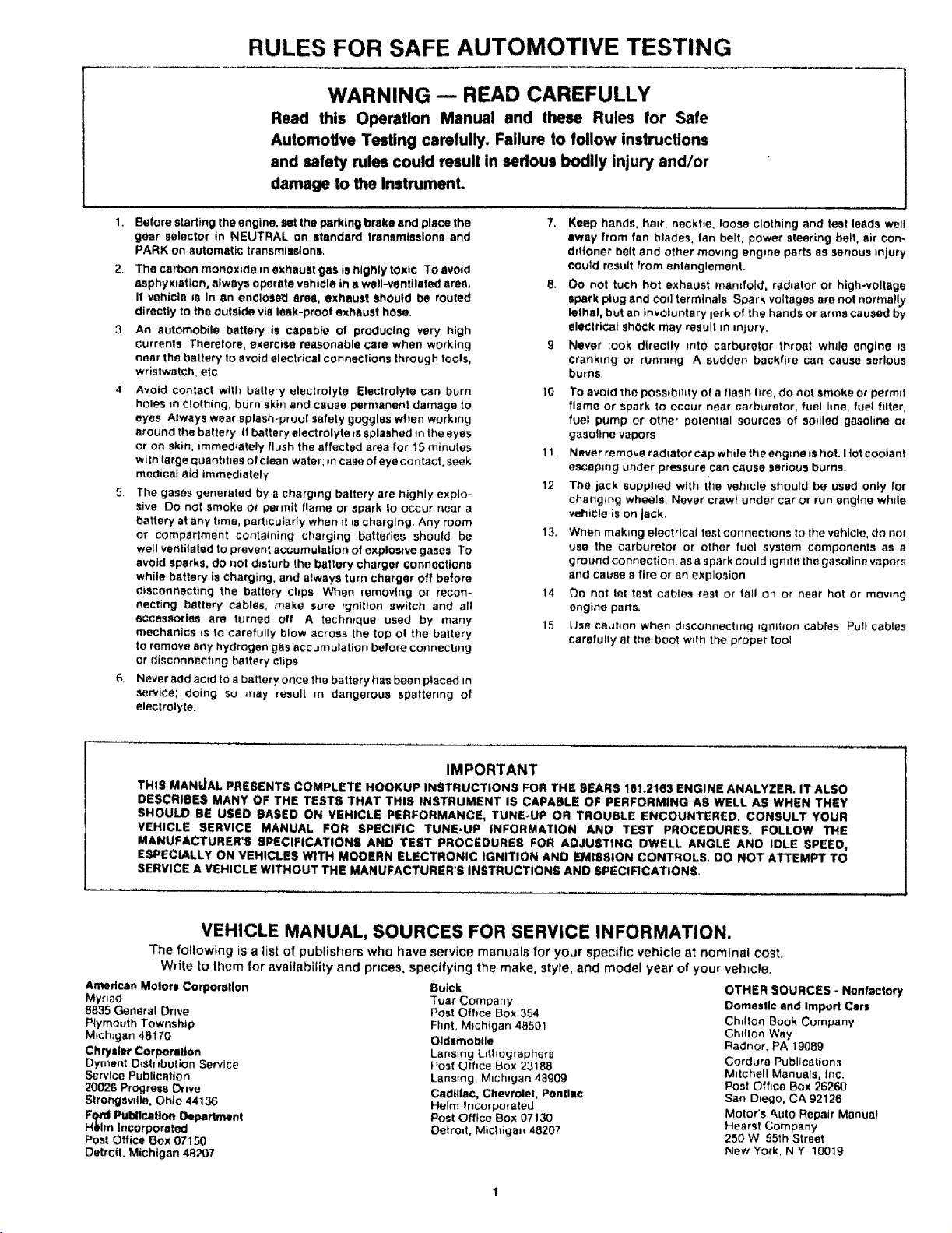
RULES FOR SAFE AUTOMOTIVE TESTING
WARNING -- READ CAREFULLY
Read this OperaUon Manual and these Rules for Safe
Automotive Testing carefully. Failure to follow instructions
and safety rules could result in sedous bodily injury and/or
damage to the Instrument.
1.
Before starting the engine, set the parking brake and place the
gear selector in NEUTRAL on standard transmissions and
PARK on automatic transmiasionl,
2. The carbon monoxide m exhaustgas is highly tOxiC To avoid
asphyxiation, always operate vehicle in • well-ventilated ares,
If vehicle ss tn an enclose_l area, exhaust should be routed
directly to the outside vie leak-proof exhaust hose.
3 An automobile battery is capabfe of producing very high
currents Therefore, exercise reasonable care when working
near the battery to avoid electrical connections through tools,
wristwatch, etc
4 Avoid contact with battery electrolyte Electrolyte can burn
holes m clothing, burn skin and cause permanent damage to
eyes Always wear splash-proof safety goggles when work=ng
around the battery tf battery electrolyte rs splashed m the eyes
or on skin. immediately flush the affected area Ior 15 minutes
with targe quanhhes of clean water; m case of eye contact, seek
medical atd immediately
5. The gases generated by a charging battery are highly explo-
sive Do not smoke or permit flame or spark Io occur near a
battery at any hme, particularly when _t=scharging. Any room
or compartment containing charging batteries should be
well ventilated to prevent accumulation of exploswe gases To
avoid sparks, do not disturb the baltery charger connections
while battery is charging, and always turn charger off before
disconnecting the battery chps When removing or recon-
necting battery cables, make sure =gnition switch and all
accessories are turned off A techmque used by many
mechanics _s to carefully blow across the top of the baltery
to remove any hydrogen gas accumulation before connechng
or disconnecting battery clips
6. Never add acid to a battery once the battery has been placed =n
service; doing so may result _n dangerous spattering of
electrolyte.
7. Keep hands, hair, neckbe, loose clothing and test leads well
away from fan blades, fan belt, power steering belt, air con-
drtioner belt and other moving engine parts as serious injury
Could result from entanglement.
8. Oo not tuch hot exhaust mamfotd, redactor or high-voltage
spark plug and Cod terminals Spark voltages are not normally
lethal, but an involuntary lark of the hands or arms caused by
electrical shock may result =n,nJury.
9 Never look directly into carburetor throat whde engine _s
cranking or running A sudden backfire can cause serious
burns.
10 To avoid the possibility of a flash fire, do not smoke or permit
flame or spark to occur near carburetor, fuel hne, fuel filter,
fuel pump or other potential sources of spdled gasoline or
gasottne vapors
1! Naver remove radlator cap while the engme ts hot, Hot coolant
escaping under pressure can cause serious burns.
12 The jack supphed with the vehicle should be used onty for
changing wheels. Never crawl under car or run engine while
vehicle is on jack.
13. When mak=ng electrical test connect=ons to the vehicle, do nol
usa the carburetor or other fuel system components as a
ground connection, as a spark could _gn=te the gasoline vapors
and cause a fire or an explosion
14 Do not let test cables rest or tall on or near hot or mowng
engine parts,
15 Use cauhon when d=sconnectmg rgmhon cables Pull cables
carefully at the boot w_th the pr'oper tool
THIS MANUAL PRESENTS COMPLETE HOOKUP INSTRUCTIONS FOR THE SEARS 161.2163 ENGINE ANALYZER. IT ALSO
DESCRIBES MANY OF THE TESTS THAT THIS INSTRUMENT IS CAPABLE OF PERFORMING AS WELL AS WHEN THEY
SHOULD BE USED BASED ON VEHICLE PERFORMANCE, TUNE-UP OR TROUBLE ENCOUNTERED. CONSULT YOUR
VEHICLE SERVICE MANUAL FOR SPECIFIC TUNE-UP INFORMATION AND TEST PROCEDURES. FOLLOW THE
MANUFACTURER'S SPECIFICATIONS AND TEST PROCEDURES FOR ADJUSTING DWELL ANGLE AND IDLE SPEED,
ESPECIALLY ON VEHICLES WITH MODERN ELECTRONIC IGNITION AND EMISSION CONTROLS. DO NOT ATTEMPT TO
SERVICE A VEHICLE WITHOUT THE MANUFACTURER'S INSTRUCTIONS AND SPECIFICATIONS,
VEHICLE MANUAL, SOURCES FOR SERVICE INFORMATION.
The following is a tiStof publishers who have service manuals for your specific vehicle at nominal cost.
Write to them for availability and prices, specifying the make, style, and model year of your vehrcle.
Amedcan Molora Corporallon
Myr=ad
8835 General Drive
Plymouth Township
M_ch_gan 48170
Ch ry$1er Corporation
Dyment D_Stnbution Service
Service Publication
20026 Progress Drive
Strongevdle, Ohio 44136
Fgcd Publication Department
Hblm Incorporated
Post Office Box 07150
Detroit, Michigan 48207
IMPORTANT
Buick
Tuar Company
Post Office Box 354
Fhnt, M_chigan 48501
Oldsmobile
Lansing L=thographers
Post Office Box 23188
Lansing. Michigan 48909
Cadillac, Chevrolet, Pontiac
Helm incorporated
Post Office Box 07130
Detroit, Michigan 48207
OTHER SOURCES - Nonfactory
Domestic and Impod Cart
Chdton Book Company
ChHton Way
Radnor, PA 19089
Cordura Publications
M_tchell Manuals, Inc.
Post Office Box 26260
San Diego, CA 92128
Motor's Auto Repair Manual
Hearst Company
250 W 55th Street
New Yo_k, N Y 10019
ENGINE ANALYZER
CONTROLS, CONNECTIONS,
AND ACCESSORIES
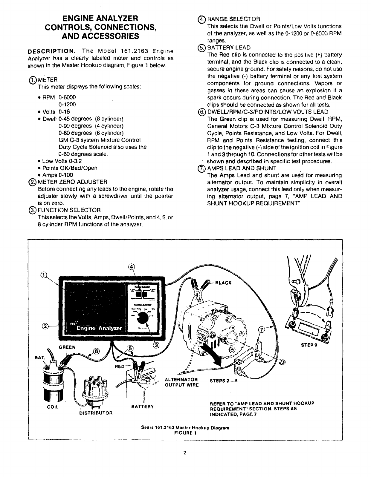
DESCRIPTION. The Model 161.2163 Engine
Analyzer has a clearly labeled meter and controls as
shown inthe Master Hookup diagram, Figure 1 below.
QMETER
This meter displays the following scares:
• RPM 0-6000
0.1200
= Volts 0-16
• Dwell 0-45 degrees (8 cylinder)
0-90 degrees (4 cylinder)
0-60 degrees (6 cylinder)
GM C_3 system Mixture Control
Duty Cycle Solenoid also uses the
0-60 degrees scale.
• Low Volts 0-3.2
• Points OK/Bad/Open
• Amps 0-!00
Q ETER ZERO ADJUSTER
Before connecting any leads to the engine, rotate the
adjuster slowly with a screwdriver until the pointer
is on zero,
@ FUNCT1ON SELECTOR
This selects the Volts, Amps, Dwell/Points, and 4, 6, or
8 cytinder RPM functions of the analyzer.
Q ANGE SELECTOR
This selects the Dwell or Points/Low Volts lunctions
of the analyzer, as well as the 0-1200 or 0-6000 RPM
ranges.
(_ BATTERY LEAD
The Red clip is connected to the positive (+) battery
terminal, and the Black clip is connected to a clean,
secure engine ground. For safety reasons, do not use
the negative (-) battery terminal or any fuel system
components for ground connections. Vapors or
gasses in these areas can cause an explosion if a
spark occurs during connection. The Red and Black
clips should be connected as shown for all tests.
(_ DWELLiRPM/C-3/POINTS/LOW VOLTS LEAD
The Green clip is used for measuring Dwetl, RPM,
General Motors C-3 Mixture Control Solenoid Duty
Cycle, Points Resfstance, and Low Volts. For Dwell,
RPM and Points Resistance testing, connect this
clip to the negative (-) side of the ignition coi! in Figure
i and 3 through 10, Connections for other tests will be
* shown and described in specific test procedures.
Q AMPS LEAD AND SHUNT
The Amps Lead and shunt are used for measuring
alternator output. To maintain simplicity in overall
analyzer usage, connect this lead only when measur-
ing alternator output, page 7, "AMP LEAD AND
SHUNT HOOKUP REQUIREMENT"
COIL
GREEN
DISTRIBUTOR
ALTERNATOR
OUTPUT W!RE
BATTERY
Sears 161.2163 Master Hookup Diagram
FIGURE 1
STEP 9
STEPS 2 --S
REFER TO "AMP LEAD AND SHUNT HOOKUP
REQUIREMENT" SECTION, STEPS AS
INDICATED, PAGE 7
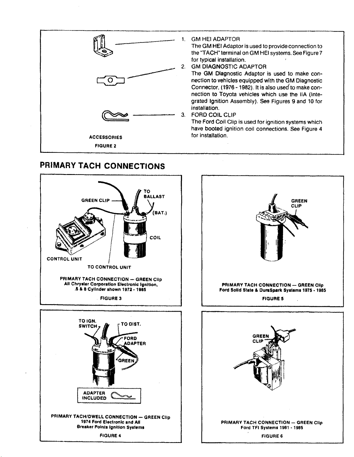
ACCESSORIES
FIGURE 2
PRIMARY TACH CONNECTIONS
TO
GREEN CLIP
BALLAST
1+ GM HEI ADAPTOR
The GM HEt Adaptor isused to provideConnection to
the "TACH" terminal on GM HEt systems. See Figure 7
for typical installation.
2+ GM DIAGNOSTIC ADAPTOR
The GM Diagnostic Adaptor is used to make con-
nection tovehicles equipped with the GM Diagnostic
Connector, (1976 - 1982). It isalso used'to makecon-
nection to Toyota vehicles which use the tlA (Inte-
grated Ignition Assembly). See Figures 9 and 10 for
installatiOn.
3. FORD COIL CLIP
The Ford Coil Clip is usedfor ignition systemswhich
have booted ignition coil connectiOnS.See Figure 4
for installation,
GREEN
CLIP
BAT.)
CONTROL UNIT
TO CONTROL UNIT
PRIMARY TACH CONNECTION -- GREEN Clip
At! Chrysler Corporation Electronic ignition,
,6 & 8 Cylinder shown 1972 - 1985
+ FIGURE 3
............................. ,,,,r,,
TO IGN.
SWITCH .TO DIST,
INCLUDED
ADAPTER ]
COIL
PRIMARY TACH CONNECTION -- GREEN Clip
Ford Solid State & DuraSpark Systems 1975 • 1985
FIGURE $
GREEN___
PRIMARY TACH/DWELL CONNECTION _ GREEN Clip
1974 Ford Electronic and All
Breaker Potnls Ignition Systems
FIGURE 4
PRIMARY TACH CONNECTION -- GREEN Clip
FOrd TFI Systems 1981 - 1985
FIGURE 6
 Loading...