

Craftsman 152229010 Owner’s Manual
_truction anu
rE lo..L"
3/4 Horsepower (continuous duty)
1-1/2 Horsepower (maximum developed)
16-Speed, Step Punmey
215 - 2720 R.P.M. Drill Speed Range
1 iLL P SS
Model No.
152.229010
®
Ji
C S
FOR YOUR OWN SAFETY; Read
and foUlow all of the Safety and
Operating Instructions before
Operating this DdH Press.
Customer Helpline
1-800-897-7709
PRease have your Model No.
and SedaR No. availabUe.
Sears, Roebuck and Co., Hoffman Estates, JL 60179 U.S.A.
Part No. OR93513
EspaSoL pg, 31

SECTmON PAGE
Warranty..........................................................................................................................................................................2
ProductSpecifications...................................................................................................................................................3
Safetymnstructions.........................................................................................................................................................4
Guidelinesforextension cords ..................................................................................................................................... 5
Grounding mnstructions .................................................................................................................................................. 6
Specific Safety mnstructions .......................................................................................................................................... 7
Accessories and Attachments ...................................................................................................................................... 8
Know Your Machine ....................................................................................................................................................... 9
Carton Contents ........................................................................................................................................................... 10
AssembJy mnstructions ................................................................................................................................................. 12
Operations and Adjustment ........................................................................................................................................ 17
Maintenance .................................................................................................................................................................. 26
Troubleshooting Guide ................................................................................................................................................ 27
Part List ......................................................................................................................................................................... 28
EspaSol .......................................................................................................................................................................... 3!
Service Information ........................................................................................................................................ Back Page
ONE-YEAR FULL WARRANTY ON CRAFTSMAN TOOL
if this Craftsman tool fails due to a defect in material or workmanship within one year from the date of purchase,
CALL 1-800-4-MY-HOME _)TO ARRANGE FOR FREE REPAIR,
This warranty applies only while this tool is in the United States,
This warranty gives you specific legal rights, and you may also have other rights, which vary from state to state,
Sears, Roebuck and Co,, Dept 817WA, Hoffman Estates, IL 60179
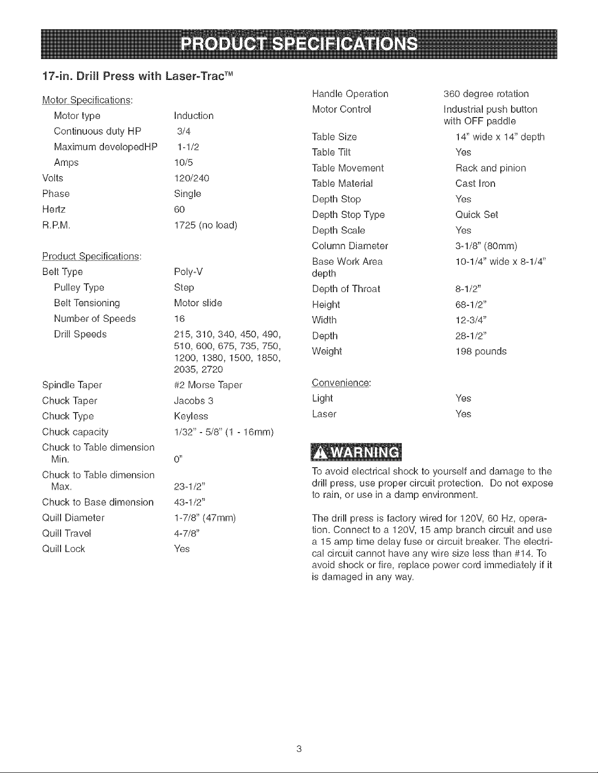
17°in. Drill Press with Laser°Trac TM
Motor Specifications:
Motor type induction
Continuous duty HP 3/4
Maximum developedHP 1=1/2
Amps 10/5
Volts 120/240
Phase Single
Hertz 60
R,P,M, 1725 (no load)
Product Specifications:
Belt Type
Pulley Type
Poly=V
Step
Motor slide
Number of Speeds
Drill Speeds
16
215, 310, 340, 450, 490,
51O, 600, 675, 735,750,
1200, 1380, 1500, 1850,
2035, 2720
Spindle Taper
Chuck Taper
Chuck Type
Chuck capacity
#2 Morse Taper
Jacobs 3
Keyless
1/32" =5/8" (1 =16mm)
Chuck to Table dimension
Min,
O _
Chuck to Table dimension
Max, 23-1/2"
Chuck to Base dimension 43ol/2"
Quill Diameter 1=7/8"(47mm)
Quill Travel 4=7/8"
Quill Lock Yes
Handle Operation
Motor Control
360 degree rotation
Industrial push button
with OFF paddle
Table Size
Table Tilt
Table Movement
Table Material
Depth Stop
Depth Stop Type
Depth Scab
Column Diameter
Base Work Area
14" wide x 14" depth
Yes
Rack and pinion
Cast iron
Yes
Quick Set
Yes
3-1/8" (80ram)
10=1/4" wide x 8=1/4"
depth
Depth of Throat
Height
Width
Depth
Weight
8=1/2"
68=1/2"
12=3/4"
28-1/2"
198 pounds
Convenience:
Light Yes
Laser Yes
To avoid electrical shock to yourself and damage to the
drill press, use proper circuit protection, Do not expose
to rain, or use in a damp environment,
The drill press is factory wired for 120V, 60 Hz, opera-
tion, Connect to a 120V, 15 amp branch circuit and use
a 15 amp time delay fuse or circuit breaker, The electri-
cal circuit cannot have any wire size less than #14, To
avoid shock or fire, replace power cord immediately if it
is damaged in any way,
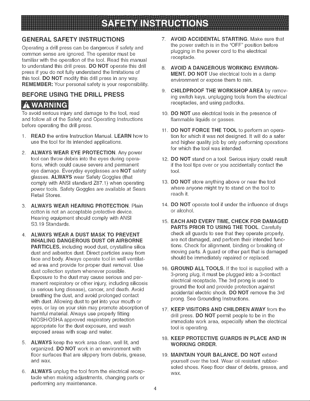
GENERAL SAFETY iNSTRUCTiONS
Operating a drill press can be dangerous if safety and
common sense are ignored, The operator must be
familiar with the operation of the tool, Read this manual
to understand this drill press, DO NOT operate this drill
press if you do not fully understand the limitations of
this tool, DO NOT modify this drill press in any way,
REMEMBER: Your personal safety is your responsibility,
BEFORE USUNG THE DF_ULLPRESS
7,
AVOID ACCIDENTAL STARTING, Make sure that
the power switch is in the "OFF" position before
plugging in the power cord to the electrical
receptacle,
8,
AVOID A DANGEROUS WORKING ENVIRON-
MENT. DO NOT Use electrical tools in a damp
environment or expose them to rain.
9,
CHILDPROOF THE WORKSHOP AREA by remov-
ing switch keys, unplugging tools from the electrical
receptacles, and using padlocks,
To avoid serious injury and damage to the tool, read
and follow all of the Safety and Operating instructions
before operating the drill press,
1, READ the entire instruction Manual, LEARN how to
use the tool for its intended applications,
2,
ALWAYS WEAR EYE PROTECTION, Any power
tool can throw debris into the eyes during opera-
tions, which could cause severe and permanent
eye damage, Everyday eyeglasses are NOT safety
glasses, ALWAYS wear Safety Goggles (that
comply with ANSi standard Z87,1) when operating
power tools, Safety Goggles are available at Sears
Retail Stores,
3, ALWAYS WEAR HEARING PROTECTION, Plain
cotton is not an acceptable protective device,
Hearing equipment should comply with ANSi
$3,19 Standards,
4, ALWAYS WEAR A DUST MASK TO PREVENT
INHALING DANGEROUS DUST OR AIRBORNE
PARTICLES, including wood dust, crystalline silica
dust and asbestos dust, Direct particles away from
face and body, Always operate tool in well ventilat-
ed area and provide for proper dust removal, Use
dust collection system whenever possible,
Exposure to the dust may cause serious and per-
manent respiratory or other injury, including silicosis
(a serious lung disease), cancer, and death, Avoid
breathing the dust, and avoid prolonged contact
with dust, Allowing dust to get into your mouth or
eyes, or lay on your skin may promote absorption of
harmful material, Always use properly fitting
NIOSH/OBHA approved respiratory protection
appropriate for the dust exposure, and wash
exposed areas with soap and water,
5,
ALWAYS keep the work area clean, well lit, and
organized, DO NOT work in an environment with
floor surfaces that are slippery from debris, grease,
and wax,
6, ALWAYS unplug the tool from the electrical recep-
tacle when making adjustments, changing parts or
performing any maintenance,
10,
DO NOT use electrical tools in the presence of
flammable liquids or gasses,
11,
DO NOT FORCE THE TOOL to perform an opera-
tion for which it was not designed, it wiii do a safer
and higher quality job by only performing operations
for which the tool was intended,
12,
DO NOT stand on a tool, Serious injury could result
if the tool tips over or you accidentally contact the
tool,
13,
DO NOT store anything above or near the tool
where anyone might try to stand on the tool to
reach it,
14,
DO NOT operate tool if under the influence of drugs
or alcohol,
15,
EACH AND EVERY TIME, CHECK FOR DAMAGED
PARTS PRIOR TO USING THE TOOL. Carefully
check all guards to see that they operate properly,
are not damaged, and perform their intended func-
tions, Check for alignment, binding or breaking of
moving parts, A guard or other part that is damaged
should be immediately repaired or replaced,
16,
GROUND ALL TOOLS, if the tool is supplied with a
3-prong plug, it must be plugged into a 3-contact
electrical receptacle, The 3rd prong is used to
ground the tool and provide protection against
accidental electric shock, DO NOT remove the 3rd
prong, See Grounding instructions,
17,
KEEP VISITORS AND CHILDREN AWAY from the
drill press, DO NOT permit people to be in the
immediate work area, especially when the electrical
tool is operating,
18,
KEEP PROTECTIVE GUARDS IN PLACE AND IN
WORKING ORDER,
19,
MAINTAIN YOUR BALANCE. DO NOT extend
yourself over the tool. Wear oil resistant rubber-
soled shoes. Keep floor clear of debris, grease, and
wax,
20, MAINTAIN TOOLS WITH CARE, Always keep tools
clean and in good working order, Keep all blades
and tool bits sharp,
21, NEVER LEAVE A RUNNING TOOL UNATTENDED,
Turn the power switch to the OFF position, DO
NOT leave the tool until it has come to a complete
stop,
22, REMOVE ALL MAINTENANCE TOOLS from the
immediate area prior to turning the tool ON,
23, SECURE ALL WORK, When it is possibb, use
damps or jigs to secure the workpbce, This is safer
than attempting to hold the workpbce with your
hands,
24, STAY ALERT, watch what you are doing, and use
common sense when operating a power tool, DO
NOT USE a tool wNe tired or under the influence
of drugs, abohol, or medication, A moment of
inattention whib operating power tools may resWt
in serious personal injury,
25, USE ONLY RECOMMENDED ACCESSORIES,
Use of incorrect or improper accessories could
cause serious injury to the operator and cause
damage to the tool, if in doubt, check the instruction
manual that comes with that particular accessory,
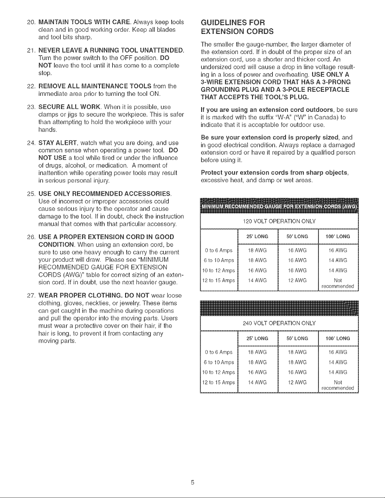
GUIDEUNES FOR
EXTENSUON CORDS
The smaller the gauge-number, the larger diameter of
the extension cord, if in doubt of the proper size of an
extension cord, use a shorter and thicker cord, An
undersized cord wiii cause a drop in line voltage result-
ing in a loss of power and overheating, USE ONLY A
3-WIRE EXTENSION CORD THAT HAS A 3-PRONG
GROUNDING PLUG AND A 3-POLE RECEPTACLE
THAT ACCEPTS THE TOOL'S PLUG.
if you are using an extension cord outdoors, be sure
it is marked with the suffix "W-A" ("W" in Canada) to
indicate that it is acceptable for outdoor use,
Be sure your extension cord is property sized, and
in good electrical condition, Always replace a damaged
extension cord or have it repaired by a qualified person
before using it,
Protect your extension cords from sharp objects,
excessive heat, and damp or wet areas,
120 VOLT OPERATION ONLY
26, USE A PROPER EXTENSION CORD IN GOOD
CONDITION, When using an extension cord, be
sure to use one heavy enough to carry the current
your product will draw, Please see "MiNiMUM
RECOMMENDED GAUGE FOR EXTENSION
CORDS (AWG)" table for correct sizing of an exten-
sion cord, if in doubt, use the next heavier gauge,
27, WEAR PROPER CLOTHING. DO NOT wear loose
clothing, gloves, neckties, or jewelry, These items
can get caught in the machine during operations
and pull the operator into the moving parts, Users
must wear a protective cover on their hair, if the
hair is long, to prevent it from contacting any
moving parts,
0 to 6 Amps
6 to 10 Amps
10to 12 Amps
12 to 15 Amps
0 to 6 Amps
6 to 10 Amps
10to 12 Amps
12 to 15 Amps
25'LONG 50' LONG 100' LONG
18 AWG
18 AWG
16 AWG
14 AWG
240 VOLT OPERATION ONLY
25' LONG
18 AWG
18 AWG
16 AWG
14 AWG
16 AWG
16 AWG
16 AWG
12 AWG
50' LONG
18 AWG
18 AWG
16 AWG
12 AWG
16 AWG
14 AWG
14 AWG
Not
recommended
100' LONG
16 AWG
14 AWG
14 AWG
Not
recommended
THINSTOOL MUST BE GROUNDED WHmLEmNUSE
TO PROTECT THE OPERATOR FROM ELECTRmC
SHOCK.
mNTHE EVENT OF A MALFUNCTmON OR BREAK-
DOWN, grounding provides the path of Ueastresistance
for eUectriccurrent and reduces the risk of eUectric
shock. This tooUis equipped with an eUectric cord that
has an equipment-grounding conductor and a ground-
ing pUug.The pUugMUST be pUuggedinto a matching
eUectdcaUreceptacle that is propedy installed and
grounded in accordance with ALL UocaUcodes and
ordinances.
DO NOT MODIFY THE PLUG PROVIDED. ff it wHUnot
fit the eUectdcaUreceptacUe, have the proper eUectdcaU
receptacle installed by a qualified electrician.
IMPROPER ELECTRICAL CONNECTION of the equip°
ment-grounding conductor can result in risk of electric
shock. The conductor with the green insulation (with or
without yellow stripes) is the equipment-grounding
conductor. DO NOT connect the equipment-grounding
conductor to a live terminal if repair or replacement of
the electric cord or plug is necessary.
USE ONLY A 3-WIRE EXTENSION CORD THAT HAS
A 3-PRONG GROUNDING PLUG AND A 3-POLE
RECEPTACLE THAT ACCEPTS THE TOOL'S PLUG.
REPLACE A DAMAGED OR WORN CORD IMMED-
IATELY.
FOR GROUNDED, CORD-CONNECTED MACHINES
INTENDED FOR USE ON A SUPPLY CIRCUIT HAVING
A NOMINAL RATING LESS THAN 150 VOLTS.
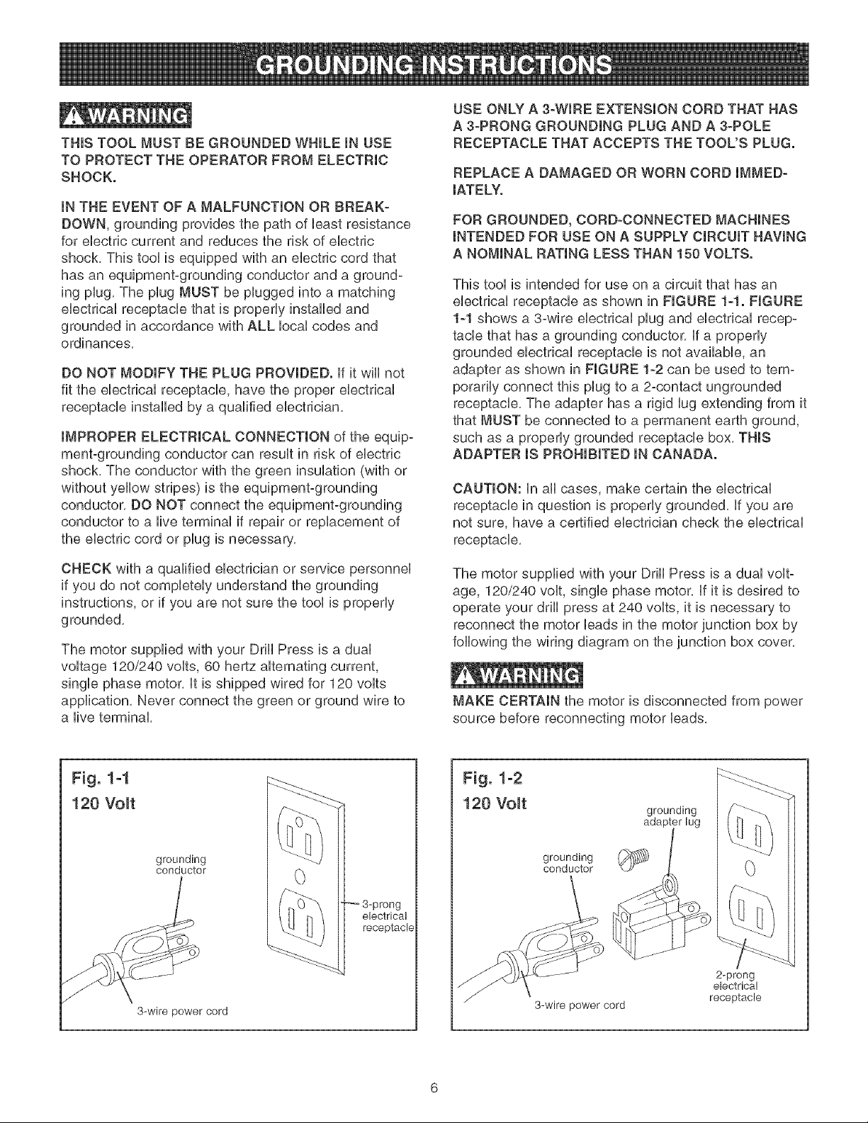
This tool is intended for use on a circuit that has an
electrical receptacle as shown in FIGURE 1-1. FIGURE
1-1 shows a 3-wire electrical plug and electrical recep-
tacle that has a grounding conductor. If a properly
grounded electrical receptacle is not available, an
adapter as shown in FIGURE 1-2 can be used to tem-
porarily connect this plug to a 2-contact ungrounded
receptacle. The adapter has a rigid lug extending from it
that MUST be connected to a permanent earth ground,
such as a properly grounded receptacle box. THIS
ADAPTER IS PROHIBITED IN CANADA.
CAUTION: In all cases, make certain the electrical
receptacle in question is properly grounded. If you are
not sure, have a certified electrician check the electrical
receptacle.
CHECK with a qualified electrician or service personnel
if you do not completely understand the grounding
instructions, or if you are not sure the tool is properly
grounded.
The motor supplied with your Drill Press is a dual
voltage 120/240 volts, 60 hertz alternating current,
single phase motor, It is shipped wired for 120 volts
application, Never connect the green or ground wire to
a live terminal,
Fig. 1-1
120 Volt
grounding
conductor
3-prong
electrical
receptacle
3-wire power cord
The motor supplied with your Drill Press is a dual volt-
age, 120/240 volt, single phase motor. If it is desired to
operate your drill press at 240 volts, it is necessary to
reconnect the motor leads in the motor junction box by
following the wiring diagram on the junction box cover.
MAKE CERTAIN the motor is disconnected from power
source before reconnecting motor leads.
Fig. 1-2
120 Volt
grounding
conductor
3-wire power cord
grounding
2-prong
electrical
receptacle
it is aUsonecessary to repUacethe 120 voUtpUug,sup-
plied with the motor, with a UL/CSA Listed pUugsuitabb
for 240 voUtsand rated current of the drHUpress. Contact
a bcaU qualified eUectrbian for proper procedures to
install the pUug.The drHUpress must compUy with aH
bcaU and nationaU eUectrbaUcodes after the 240 voUt
pUugis installed.
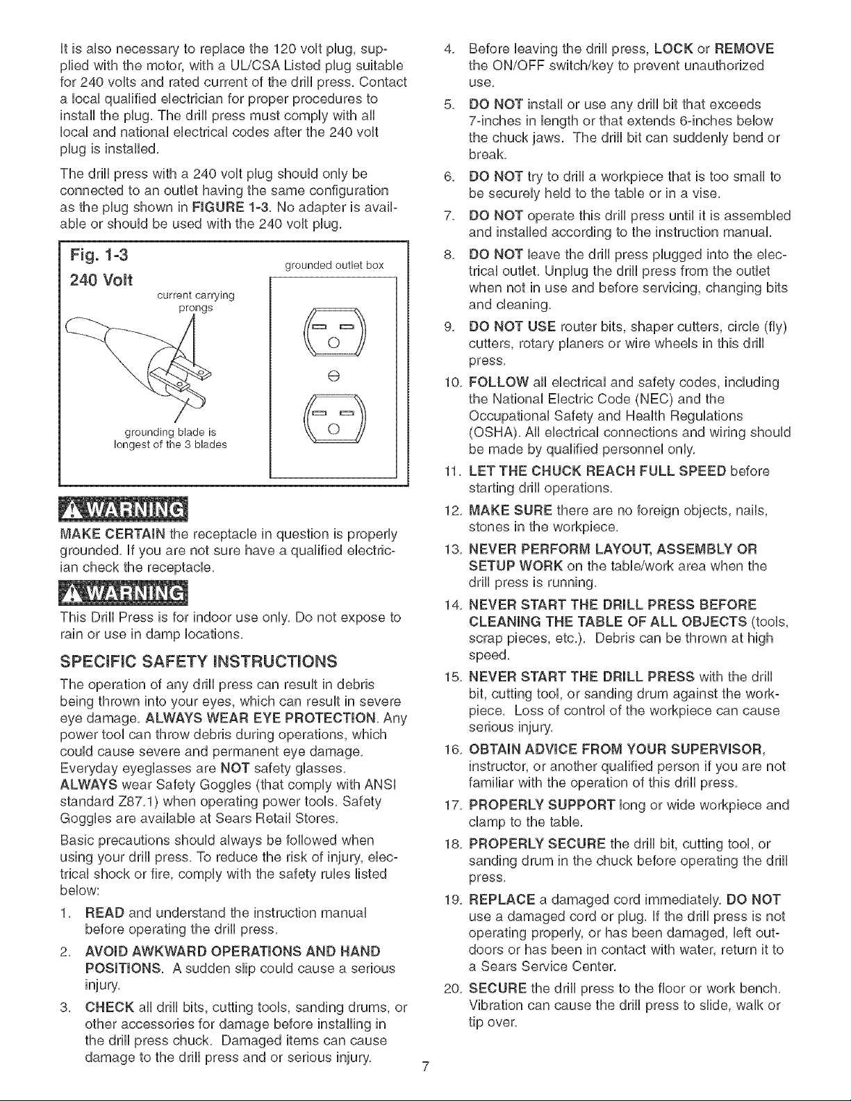
The drHUpress with a 240 voUtpUugshouUd onUybe
connected to an outlet having the same configuration
as the pUugshown in FIGURE 1-3. No adapter is avaiP
able or should be used with the 240 volt plug.
Fig. 1-3
grounded outlet box
240 Volt
current carrying
prongs
6)
grounding blade is
longest of the 3 blades
MAKE CERTAIN the receptacle in question is properly
grounded. If you are not sure have a qualified ebctric-
ian check the receptacle.
This Drill Press is for indoor use only. Do not expose to
rain or use in damp locations.
SPECIFIC SAFETY INSTRUCTIONS
The operation of any drill press can result in debris
being thrown into your eyes, which can result in severe
eye damage. ALWAYS WEAR EYE PROTECTION. Any
power tool can throw debris during operations, which
could cause severe and permanent eye damage.
Everyday eyeglasses are NOT safety glasses.
ALWAYS wear Safety Goggles (that comply with ANSI
standard Z87.1) when operating power tools. Safety
Goggles are available at Sears Retail Stores.
Basic precautions should always be followed when
using your drill press. To reduce the risk of injury, ebc-
trical shock or fire, comply with the safety rules listed
below:
1. READ and understand the instruction manual
before operating the drill press.
2, AVOID AWKWARD OPERATIONS AND HAND
POSITIONS. A sudden slip could cause a serious
injury.
3. CHECK all drill bits, cutting tools, sanding drums, or
other accessories for damage before installing in
the drill press chuck. Damaged items can cause
damage to the drill press and or serious injury.
4. Before leaving the drill press, LOCK or REMOVE
the ON/OFF switch/key to prevent unauthorized
use,
5, DO NOT install or use any drill bit that exceeds
7-inches in length or that extends 6-inches below
the chuck jaws. The drill bit can suddenly bend or
break.
6. DO NOT try to drill a workpiece that is too small to
be securely held to the table or in a vise.
7. DO NOT operate this drill press until it is assembled
and installed according to the instruction manual.
8. DO NOT leave the drill press plugged into the ebc-
trical outlet. Unplug the drill press from the outlet
when not in use and before servicing, changing bits
and cleaning.
9. DO NOT USE router bits, shaper cutters, circle (fly)
cutters, rotary planers or wire wheels in this drill
press.
10. FOLLOW all electrical and safety codes, including
the National Electric Code (NEC) and the
Occupational Safety and Health Regulations
(OSHA). All electrical connections and wiring should
be made by qualified personnel only.
11, LET THE CHUCK REACH FULL SPEED before
starting drill operations,
12, MAKE SURE there are no foreign objects, nails,
stones in the workpiece.
13, NEVER PERFORM LAYOUT, ASSEMBLY OR
SETUP WORK on the tabb/work area when the
drill press is running,
14, NEVER START THE DRILL PRESS BEFORE
CLEANING THE TABLE OF ALL OBJECTS (tools,
scrap pieces, etc.). Debris can be thrown at high
speed.
15. NEVER START THE DRILL PRESS with the drill
bit, cutting tool, or sanding drum against the work-
piece. Loss of control of the workpiece can cause
serious injury,
16, OBTAIN ADVICE FROM YOUR SUPERVISOR,
instructor, or another qualified person if you are not
familiar with the operation of this drill press,
17, PROPERLY SUPPORT long or wide workpiece and
clamp to the table,
18, PROPERLY SECURE the drill bit, cutting tool, or
sanding drum in the chuck before operating the drill
press,
19, REPLACE a damaged cord immediately, DO NOT
use a damaged cord or plug, if the drill press is not
operating properly, or has been damaged, left out-
doors or has been in contact with water, return it to
a Sears Service Center,
20, SECURE the drill press to the floor or work bench,
Vibration can cause the drill press to slide, walk or
tip over,
21,SECUREtheworkpbcefirmlyagainstthetabb,
Donotattempttodrillaworkpbcethatdoesnot
haveafiatsurfaceagainstthetabb,orthatisnot
securedbya vise, Preventtheworkpbcefrom
rotatingbydampingittothetabborbysecuringit
againstthedrillpresscolumn,Lossof controlof
theworkpbcecancauseseriousinjury,
22,SECURELYLOCKtheheadandtabbsupportto
thecolumn,andthetabbtothetabbsupport
beforeoperatingthedrillpress,
23,Thedrillpressisdesignedforhomeuseorlight
commercialdutyONLY,
24,TOREDUCETHERISKOFELECTRICAL
SHOCK,donotuseoutdoors.Donotexposeto
rain,Storeindoorsina dryarea,
25,TURNTHEDRILLPRESSOFFandunplugfrom
powersource,Waitforthedrillbit,cuttingtool,or
sandingdrumtocometoa compbteSTOPbefore
cleaningoffthetabb/workarea,removingorsecur-
ingworkpiece,orchangingsetup,
26,USEonlydrillbits,cuttingtools,sandingdrums,or
otheraccessorieswithpropershanksizerecom-
mendedinthisinstructionmanual,Thewrongsize
shankcancausedamagetothedrillpressand/or
seriousinjury,
27,USEonlyasdescribedinthisinstructionmanual,
USEaccessoriesonlyrecommendedbySears,
28,USERECOMMENDEDSPEEDSforalloperations,
Otherspeedsmaycausethemachinetomalfunc-
tioncausingdamagetothedrillpressandor
seriousinjury,
29,informationregardingthesafeandproperoperation
ofthistoolisalsoavailablefromthefollowing
sources:
PowerToolinstitute
1300SummerAvenue
Cleveland,OH44115-2851
www, powertoolinstitute,org
National Safety Council
1121 Spring Lake Drive
Itasca, IL 60143o3201
American National Standards institute
25 West 43rd Street, 4th floor
New York, NY 10036
ANSi 01,1 Safety Requirements for
Woodworking Machines, and the
U,S, Department of Labor regulations
www, osha,cLOJ
30,
SAVE THESE INSTRUCTIONS, Refer to them
frequently and use them to instruct other users,
ADDITIONAL SAFETY RULES
FOR THE LASER
1, LASER LIGHT - DO NOT STARE INTO BEAM,
APERTURE, or into a reflection from a mirror-like
surface,
2, AVOID EXPOSURE - LASER LIGHT IS EMITTED
FROM BOTH SIDES OF LASER ASSEMBLY,
Use of controls or adjustments, or performance of
procedures other than those specified herein may
result in hazardous laser light exposure,
3, DO NOT DISASSEMBLE LASER MODULE, The
laser is a CLASS mmLASER PRODUCT that can
emit laser power up to 1 mW MAX at 635 rim,
which could result in exposure with the module
disassembled, The laser unit complies with 21
CFR 1040,10 and 1040,11,
4, USE OF CONTROLS OR ADJUSTMENTS OR
PERFORMANCE OF PROCEDURES OTHER
THAN THOSE SPECIFIED HEREIN MAY RESULT
IN HAZARDOUS RADIATION EXPOSURE.
AVAILABLE ACCESSORUES
Visit your Sears Hardware Department or see the
Craftsman Power and Hand Tool Catalog for the follow-
ing accessories,
ITEM STOCK NUMBER
* Circle Cutter 25293
* Clamping Lit 26426
* 8-in, Vise 24077
* 4-in, Vise 24081
* 3-in, Vise 24071
* 21 pc, Sanding Drum Kit 25262
* 7 pc, Forstner Bit Set 25389
Sears may recommend other accessories not listed in
this manual,
See your nearest Sears Hardware Department or
Craftsman Power and Hand Tool Catalog for other
accessories,
Do not use any accessory unless you have completely
read the instruction Manual for that accessory,
Use only accessories recommended for this drill press,
Using other accessories may cause serious injury and
cause damage to the drill press,
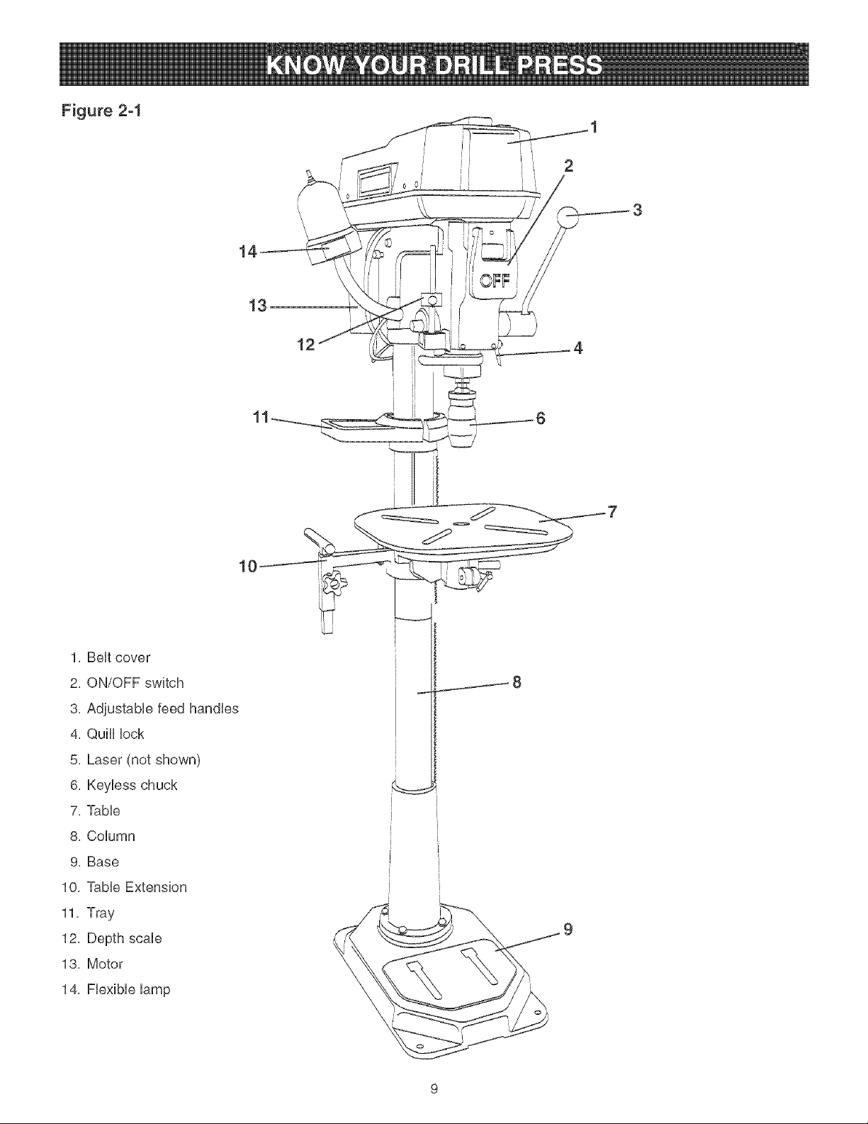
Figure 2-1
i II
12
1, BeHtcover
2, ON/OFF switch
3, AdjustabHe feed handHes
4, QulH Hock
5, Laser (not shown)
6, KeyHess chuck
7, TaMe
8, CoHumn
9, Base
10, TaMe Extension
11, Tray
12, Depth scaHe
13, Motor
14, FHexibHeHamp
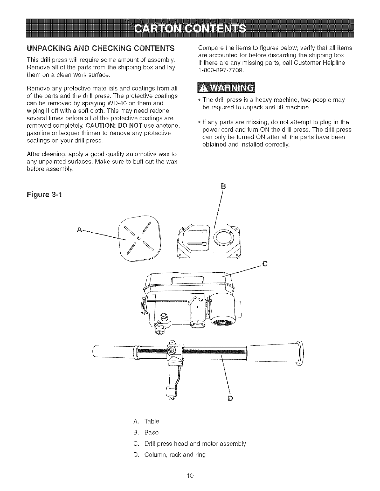
UNPACKUNG AND CHECKUNG CONTENTS
This drHUpress wHUrequire some amount of assemMy,
Remove aHof the parts from the shipping box and Uay
them on a clean work surface,
Remove any protective materiab and coatings from aH
of the parts and the drHUpress, The protective coatings
can be removed by spraying WD-40 on them and
wiping it off with a soft cloth, This may need redone
severaUtimes before aH of the protective coatings are
removed compbteUy, CAUTION: DO NOT use acetone,
gasoline or Uacquer thinner to remove any protective
coatings on your drHUpress,
After cleaning, apply a good quality automotive wax to
any unpainted surfaces, Make sure to buff out the wax
before assembly,
Figure 3-1
Compare the items to figures below; verify that all items
are accounted for before discarding the shipping box,
if there are any missing parts, call Customer Helpline
1-800-897-7709,
The drill press is a heavy machine, two people may
be required to unpack and lift machine,
if any parts are missing, do not attempt to plug in the
power cord and turn ON the drill press, The drill press
can only be turned ON after all the parts have been
obtained and installed correctly,
B
}
A, Table
B, Base
C, Drill press head and motor assembly
D, Column, rack and ring
10
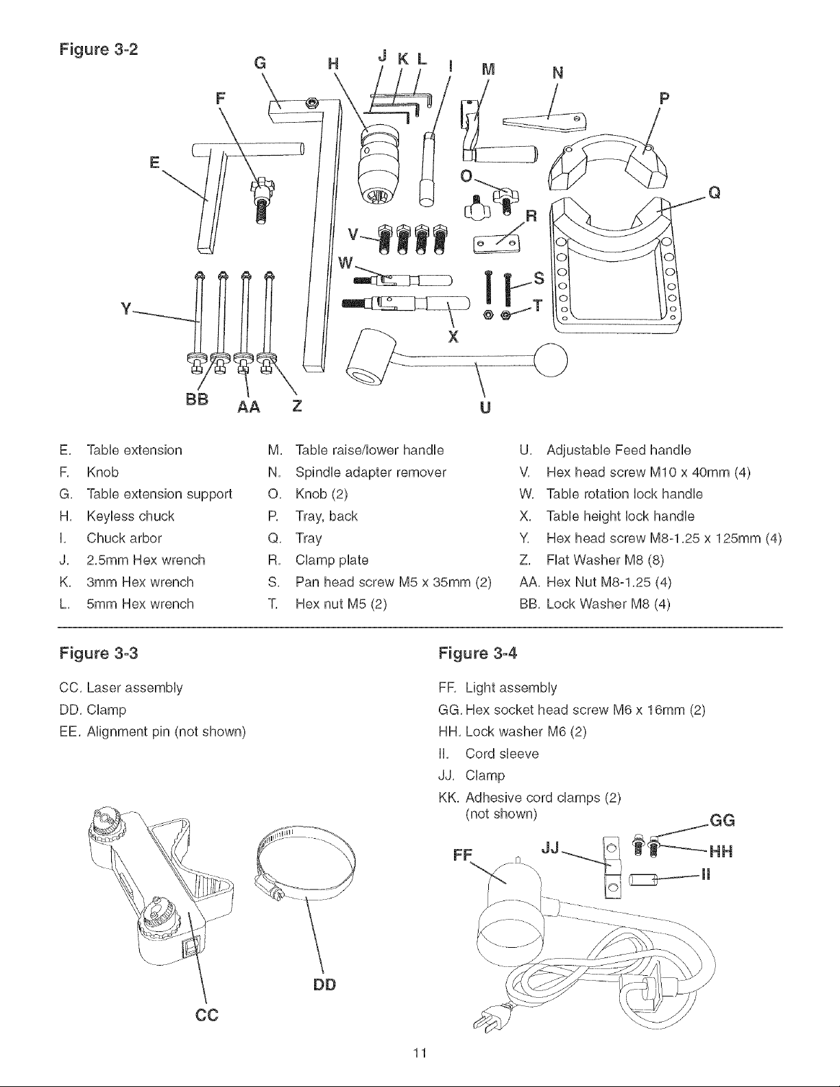
Figure 3-2
G H
JKL
F
E
BB
E, TaMe extension
F, Knob
G, TaMe extension support
H, Keyiess chuck
i, Chuck arbor
J, 2,5mm Hex wrench
K, 3mm Hex wrench
L, 5mm Hex wrench
Figure 3-3
CC, Laser assembly
DD, Clamp
EE, Alignment pin (not shown)
Z
M, TaMe rabe/Mower handle
N, Spindie adapter remover
O, Knob (2)
P, Tray, back
Q, Tray
R, CHamppilate
S, Pan head screw M5 x 35mm (2)
T, Hex nut M5 (2)
Figure 3-4
FR Light assembHy
GG, Hex socket head screw M6 x 16mm (2)
HH, Lock washer M6 (2)
Hi, Cord sieeve
JJ, CHamp
KK, Adhesive cord champs (2)
(not shown)
U, Adjustabie Feed handie
V, Hex head screw MIO x 40mm (4)
W, TaMe rotation Hockhandie
X, TaMe height Hockhandie
Y, Hex head screw M8-1,25 x 125mm (4)
Z, Fiat Washer M8 (8)
AA, Hex Nut M8-1,25 (4)
BB, Lock Washer M8 (4)
11
FF
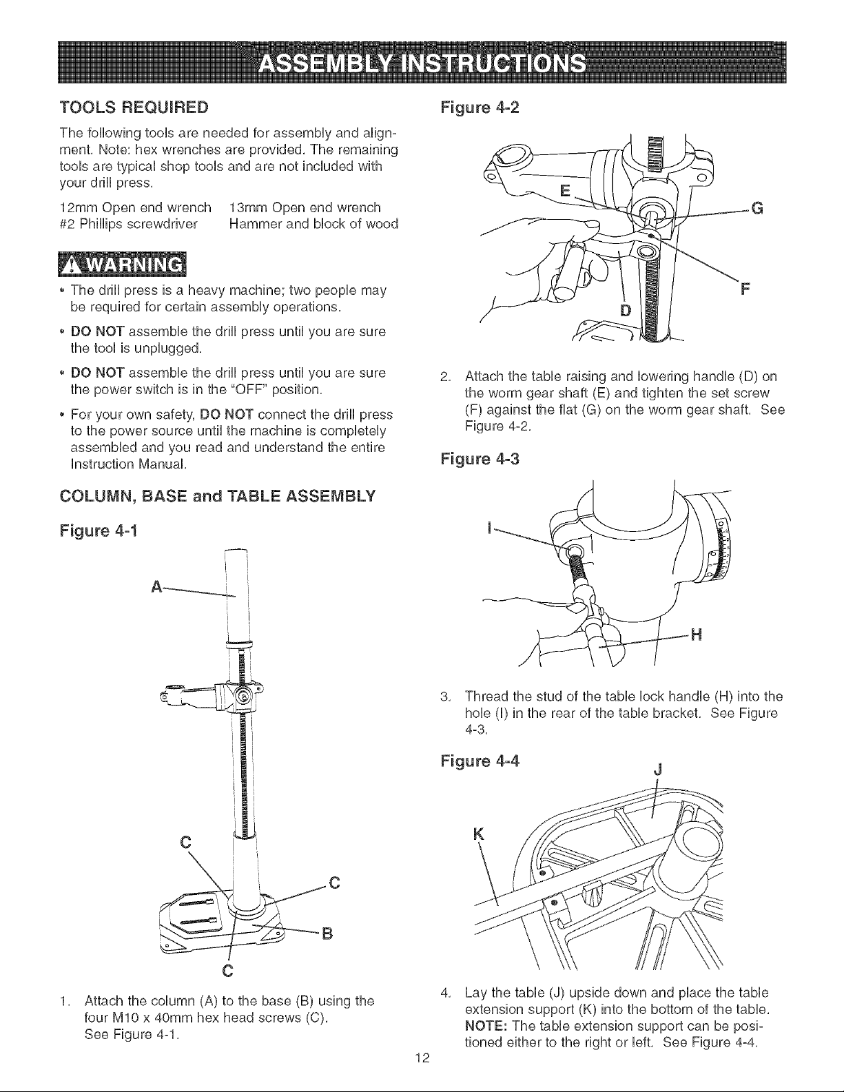
TOOLS REQUIRED
The following toob are needed for assemMy and align-
ment. Note: hex wrenches are provided. The remaining
toob are typbaU shop tooUsand are not included with
your drHUpress.
12mm Open end wrench 13mm Open end wrench
#2 PhHHpsscrewdriver Hammer and Mock of wood
The drHUpress is a heavy machine; two peopb may
be required for certain assemMy operations.
DO NOT assembb the drHUpress until you are sure
the tooUis unpUugged.
Figure 4-2
O
G
DO NOT assembb the drHUpress until you are sure
the power switch is in the "OFF" position.
For your own safety, DO NOT connect the drHUpress
to the power source until the machine is completely
assembled and you read and understand the entire
Instruction Manual.
COLUMN, BASE and TABLE ASSEMBLY
Figure 4-1
i [
2,
Attach the table raising and lowering handle (D) on
the worm gear shaft (E) and tighten the set screw
(F) against the fiat (G) on the worm gear shaft, See
Figure 4-2,
Figure 4-3
3. Thread the stud of the table lock handle (H) into the
hob (I) in the rear of the table bracket. See Figure
4-3.
Figure 4-4
J
Attach the column (A) to the base (B) using the
four MIO x 40mm hex head screws (C).
See Figure 4-1.
12
K
4,
Lay the table (J) upside down and place the table
extension support (K) into the bottom of the table.
NOTE: The table extension support can be posi-
tioned either to the right or left. See Figure 4-4.
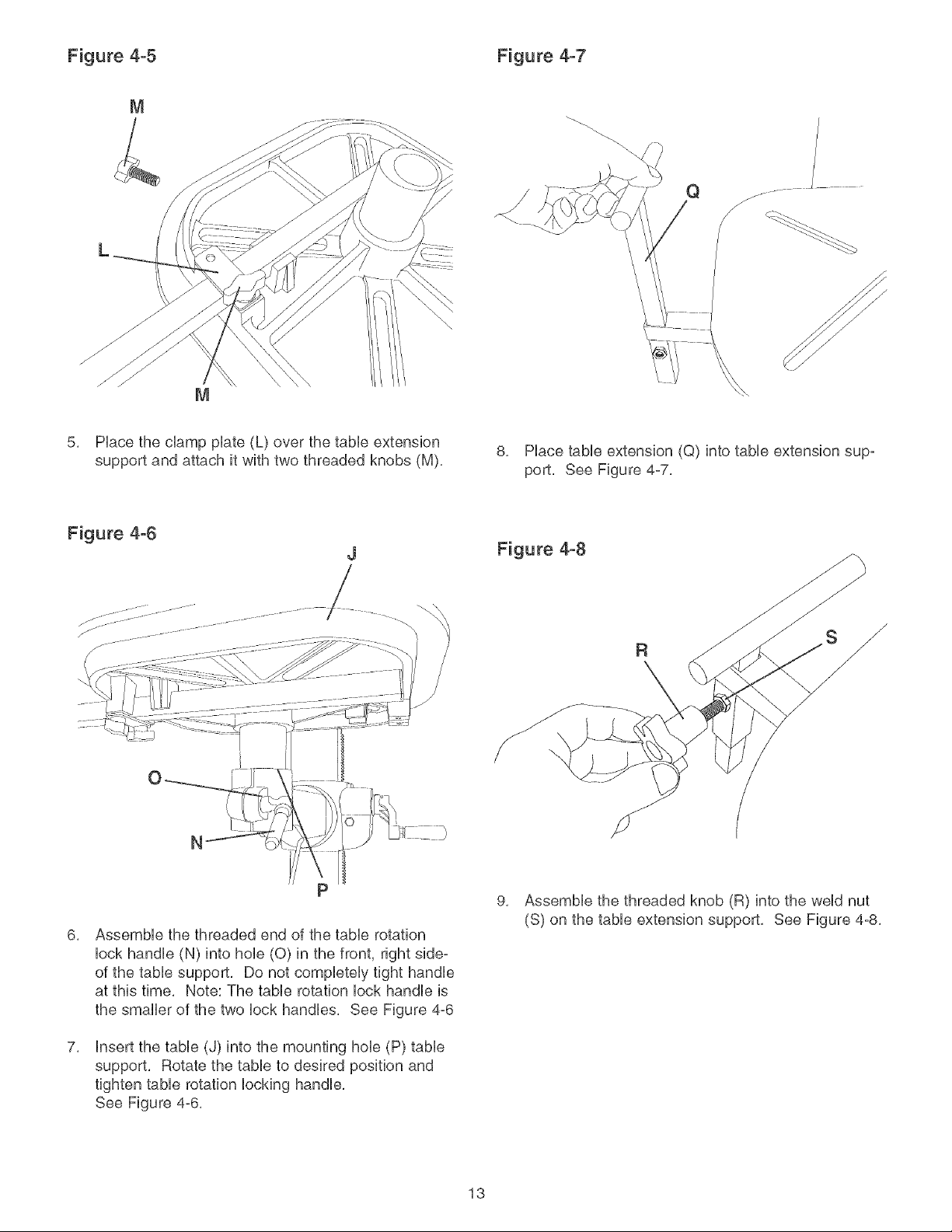
Figure 4-5 Figure 4-7
M
Q
/
C_
5, Hace the clamp plate (L) over the tame extension
support and attach it with two threaded knobs (M),
Figure 4-6
J
/
N
8, Hace tame extension (Q) into tame extension sup-
port, See Figure 4-7,
Figure 4-8
/,
R y
6,
AssemMe the threaded end of the tame rotation
lock handle (N) into hole (0) in the front, right side-
of the tame support, Do not completely tight handle
at this time, Note: The tame rotation lock handle is
the smaller of the two lock handles, See Figure 4-6
7,
Insert the tame (J) into the mounting hole (P) tame
support, Rotate the tame to desired position and
tighten tame rotation locking handle,
See Figure 4-6,
13
9,
Assemble the threaded knob (R) into the weld nut
(S) on the table extension support, See Figure 4-8,
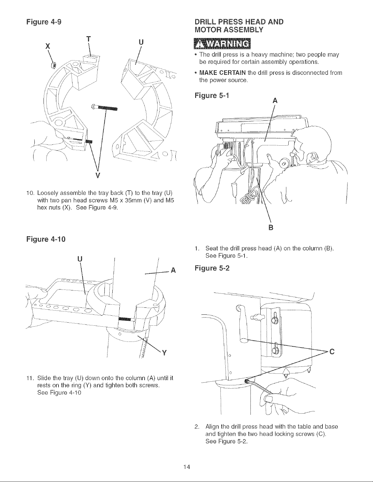
Figure 4-9 DRILL PRESS HEAD AND
MOTOR ASSEMBLY
T
X
The drHUpress is a heavy machine; two peopb may
\
be required for certain assemMy operations,
MAKE CERTAIN the drHUpress is disconnected from
the power source,
V
10, LooseUyassembb the tray back (T) to the tray (U)
with two pan head screws M5 x 35mm (V) and M5
hex nuts (X), See Figure 4-9,
Figure 4-10
U
Figure 5-1
1, Seat the drHUpress head (A) on the coUumn (B),
See Figure 5-1,
Figure 5-2
A
B
11, Slide the tray (U) down onto the column (A) until it
rests on the ring (Y) and tighten both screws,
See Figure 4-10
2, Align the drill press head with the table and base
and tighten the two head locking screws (C),
See Figure 5-2,
14
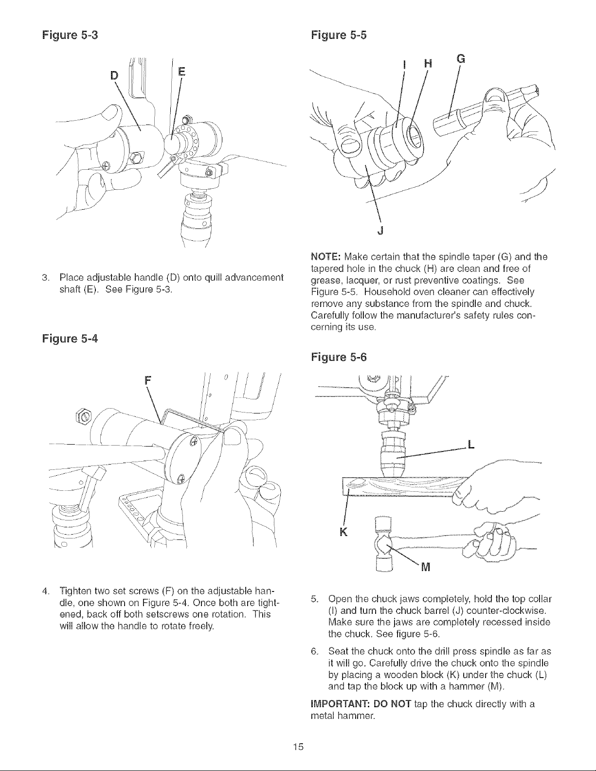
Figure 5-3 Figure 5-5
D
3, Piace adjustabie handie (D) onto quHi advancement
shaft (E), See Figure 5-3,
E
NOTE: Make certain that the spindie taper (G) and the
tapered hob in the chuck (H) are clean and free of
grease, iacquer, or rust preventive coatings, See
Figure 5-5 Househoid oven cieaner can effectiveiy
remove any substance from the spindie and chuck,
Carefuliy follow the manufacturer's safety rubs con-
cerning its use,
Figure 5-4
G
F
4,
Tighten two set screws (F) on the adjustable han-
dle, one shown on Figure 5-4, Once both are tight-
ened, back off both setscrews one rotation, This
will allow the handle to rotate freely,
Figure 5-6
K
5, Open the chuck jaws completely, hold the top collar
(I) and turn the chuck barrel (J) counter-clockwise,
Make sure the jaws are completely recessed inside
the chuck, See figure 5-6,
6, Seat the chuck onto the drill press spindle as far as
it wiii go, Carefully drive the chuck onto the spindle
by placing a wooden block (K) under the chuck (L)
and tap the block up with a hammer (M),
IMPORTANT: DO NOT tap the chuck directly with a
metal hammer,
15
LASER ASSEMBLY Figure 6-3
MAKE CERTAIN the drill press is disconnected from
the power source,
LASER LIGHT - DO NOT STARE INTO BEAM,
APERTURE, or into a reflection from a mirrorqke
surface,
Figure 6-1
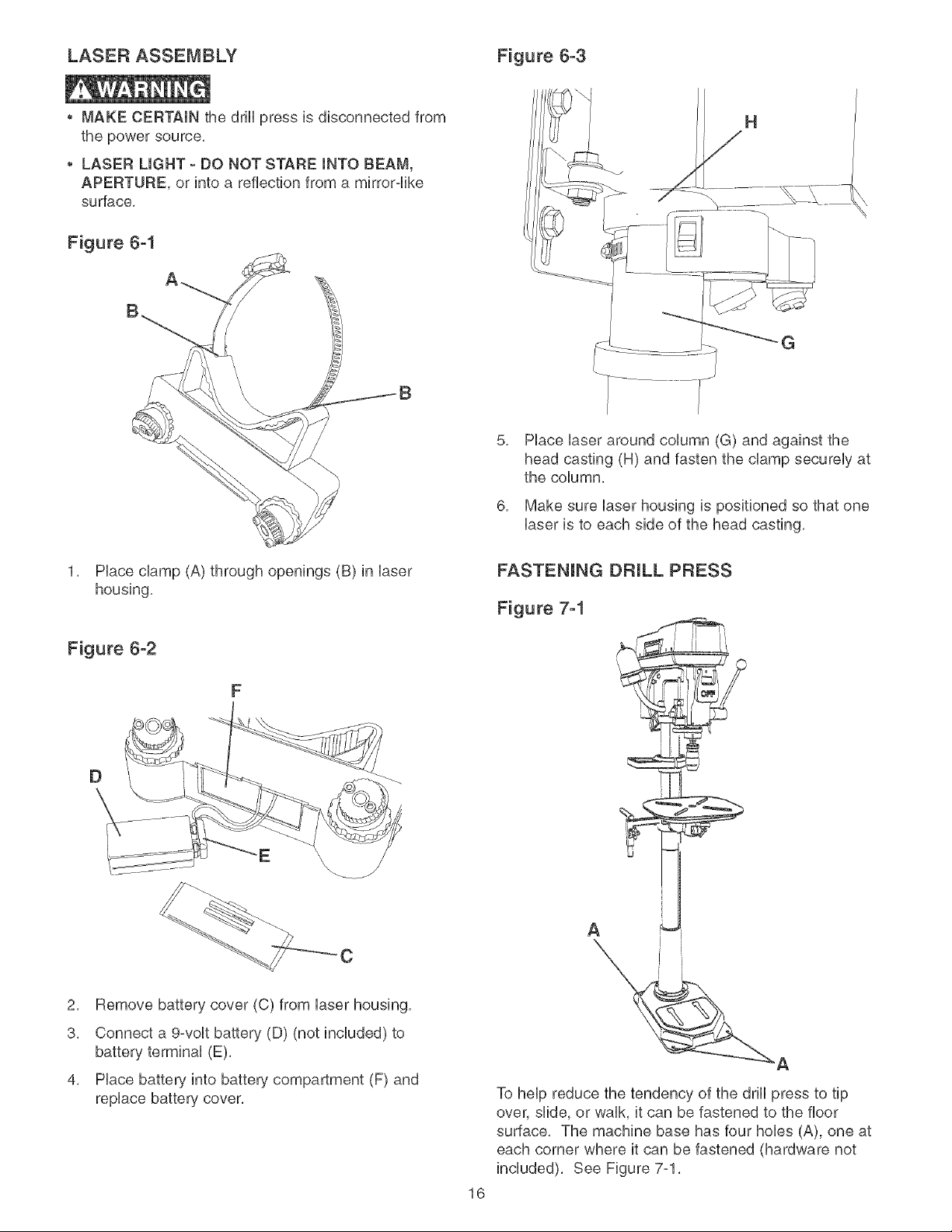
5,
Hace Uaseraround coUumn(G) and against the
head casting (H) and fasten the damp secureUy at
the coUumn,
6,
Make sure Uaserhousing is positioned so that one
Uaseris to each side of the head casting,
1, Place clamp (A) through openings (B) in laser
housing,
Figure 6-2
F
D
E
\
C
2, Remove battery cover (C) from laser housing,
A
3, Connect a 9-volt battery (D) (not included) to
battery terminal (E),
4, Place battery into battery compartment (F) and
replace battery cover,
To help reduce the tendency of the drill press to tip
over, slide, or walk, it can be fastened to the floor
surface, The machine base has four hobs (A), one at
each corner where it can be fastened (hardware not
included), See Figure 7-1,
16
DONOTexposethedrillpresstorainoroperatethe
indamplocations,
MAKESUREallpartshavebeenassembledcorrectly
andareinworkingorder,
SWITCH OPERATION
CHmLDPROOF THE WORKSHOP AREA by removing
switch keys, unplugging tools from the electrical recep-
tacles, and using padlocks,
Figure 8-1
Figure 8-2
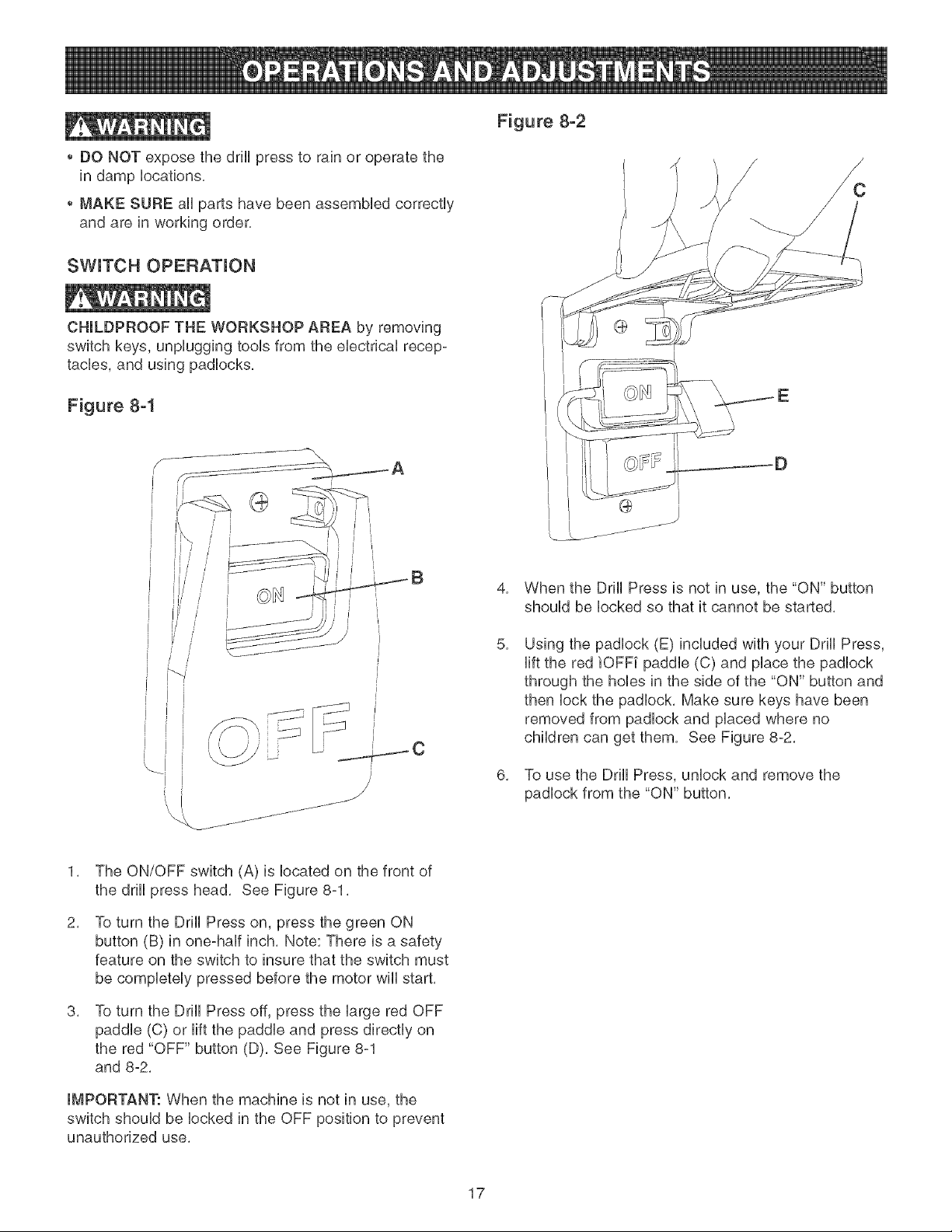
1, The ON/OFF switch (A) is located on the front of
the drill press head, See Figure 8-1,
2.
To turn the Drill Press on, press the green ON
button (B) in one-half inch, Note: There is a safety
feature on the switch to insure that the switch must
be completely pressed before the motor will start,
8.
To turn the Drill Press off, press the large red OFF
paddle (C) or lift the paddle and press directly on
the red "OFF" button (D), See Figure 8-1
and 8-2,
4.
When the Drill Press is not in use, the "ON" button
should be locked so that it cannot be started,
8.
Using the padlock (E) included with your Drill Press,
lift the red iOFF[ paddle (C) and place the padlock
through the hobs in the side of the "ON" button and
then lock the padlock, Make sure keys have been
removed from padlock and placed where no
children can get them, See Figure 8-2,
8.
To use the Drill Press, unlock and remove the
padlock from the "ON" button,
IMPORTANT: When the machine is not in use, the
switch should be locked in the OFF position to prevent
unauthorized use,
17
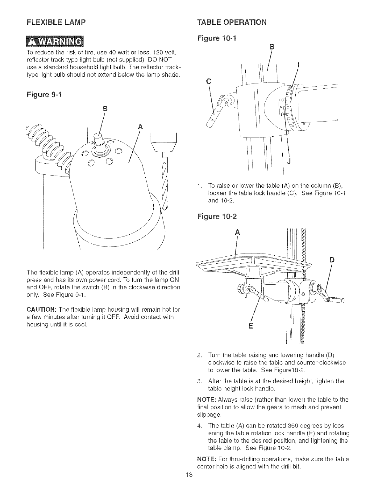
FLEXUBLE LAMP
To reduce the risk of fire, use 40 watt or less, 120 volt,
reflector track-type Hightbuib (not supplied), DO NOT
use a standard househoid Hightbuib, The reflector track-
type Hightbuib shouid not extend bellow the iamp shade,
Figure 9-1
B
A
© ©
TABLE OPERATION
Figure 10-1
B
C
1, To raise or lower the table (A) on the column (B),
loosen the table lock handle (C), See Figure 10-1
and 10-2,
The flexible lamp (A) operates independently of the drill
press and has its own power cord, To turn the lamp ON
and OFF, rotate the switch (B) in the clockwise direction
only, See Figure 9-1,
CAUTION: The flexible lamp housing wiii remain hot for
a few minutes after turning it OFR Avoid contact with
housing until it is cook
Figure 10-2
A
E
2, Turn the table raising and lowering handle (D)
clockwise to raise the table and counter-clockwise
to lower the table, See Figure10-2,
3, After the table is at the desired height, tighten the
table height lock handle,
NOTE: Always raise (rather than lower) the table to the
final position to allow the gears to mesh and prevent
slippage,
4, The table (A) can be rotated 360 degrees by loos-
ening the table rotation lock handle (E) and rotating
the table to the desired position, and tightening the
table clamp, See Figure 10-2,
NOTE: For thru-drilling operations, make sure the table
center hob is aligned with the drill bit,
18
 Loading...