

Craftsman 152221140 Owner’s Manual
Owner's Manual
CRRFr MRH
1.5 Horsepower (continuous duty)
2 Horsepower (maximum developed)
3450 R.P.M. (no load R.P.M.)
10-in. LE SAW
Model No.
152.221140
CAUTION:
FOR YOUR OWN SAFETY; Read
and follow all of the Safety and
Operating Instructions before
Operating this Table Saw.
Sears, Roebuck and Co., Hoffman Estates, IL 60179 U.S.A.
Part No. OR91551
Revision: D Espa5ol pg. 49
Customer Helpline
1-800-897-7709
Please have your Model No.
and Serial No. available.

SECTION PAGE
Warranty .......................................................................................................................................................................... 2
Product Specifications .................................................................................................................................................. 2
Glossary of Terms .......................................................................................................................................................... 3
Safety instructions ......................................................................................................................................................... 4
Guidelines for Extension Cords ................................................................................................................................... 5
Grounding instructions ................................................................................................................................................. 6
Specific Safety instructions for Table Saw .................................................................................................................. 7
Accessories and Attachments ...................................................................................................................................... 9
Carton Contents ........................................................................................................................................................... 11
Know Your Table Saw .................................................................................................................................................. 14
Assembly instructions ................................................................................................................................................. 15
Operations and Adjustment ........................................................................................................................................ 25
Maintenance .................................................................................................................................................................. 39
Troubleshooting Guide ................................................................................................................................................ 41
Part List ......................................................................................................................................................................... 42
Espanol ......................................................................................................................................................................... 48
Service information ...................................................................................................................................................... 92
FULL ONE YEAR WARRANTY
If this product fails due to a defect in material or workmanship within one year from the date of purchase, return it
to the nearest Sears Service Center for repair, free of charge.
If this product is used for commercial or rental purposes, this warranty applies only for 90 days from date of purchase.
This warranty gives you specific legal rights, and you may also have other rights, which vary, from state to state.
Sears, Roebuck and Co., Dept 817 WA, Hoffman Estates, IL 60179
lO-in. Table Saw
Motor type Induction
Continuous duty HP 1.5
Maximum developed HP 2
Amps 15/7.5
Volts 120/240
Hertz 60
RPM 3450 R.P.M. (no load R.P.M.)
Blade tilt Left tilt
Blade drive Poly-V Belt
Blade diameter 10-in.
Blade arbor 5/8-in.
Number of teeth 40
Blade speed 3450 R.P.M.
Fence type Front locking, Extruded
aluminum Fence and Rails
Max depth-of-cut at 90-degree 3-3/8-in.
Max depth-of-cut at 45-degree 2-1/4-in.
Max rip to the right of the blade 25-in.
Max rip to the left of the blade 24-in.
Table in front of blade at max depth-of-cut 12-1/2-in.
Max dado width 13/16-in.
Max dado blade diameter 8-in.
Left and right table wing lO-in, Cast Iron
Weight of table saw 350 Ibs.
To avoid electrical shock to yourself and damage to the
Table Saw, use proper circuit protection. Do not expose
to rain, or use in a damp environment.
The Table Saw is factory wired for 120V, 60 Hz, opera-
tion. Connect to a 120V, 15 amp branch circuit and use
a 15 amp time delay fuse or circuit breaker. The electri-
cal circuit cannot have any wire size less than #14. To
avoid shock or fire, replace power cord immediately if it
is damaged in any way.

Anti-KickbackFingers- Asafetydeviceattachedtothe
bladeguardandsplitterassemblydesignedtostopa
workpiecefrombeingthrownbackduringacuttingopera-
tion.
Arbor- Theshaftonwhichthebladeoraccessorycut-
ting-toolismounted.
BevelCut- Theoperationofmakinganycutwiththe
bladesetonadegreeotherthan90degrees.
CompoundCut- Theoperationofmakingbotha bevel
andamitercutatonetime.
Crosscut- Theoperationofmakingacutacrossthe
grainorwidthofaworkpiece.
Dado- Anon-throughcutthatproducesasquarenotch.
Adadoistypicallyfrom1/8-in.to13/16-in.wide.Adado
requiresaspecialsetofblades,notincludedwiththis
tablesaw.
Kerf- Thematerialremovedbythebladeinthework-
pieceduringanycuttingoperation.
Kickback- Whentheworkpieceisthrownbacktowards
theoperatorduringacuttingoperationwhentheworkpiece
initiallycontactsthebladeoriftheworkpiecepinchesthe
blade.Kickbackisdangerousandcanresultinserious
injury.
MiterCut- Theoperationofmakingacutusingthemiter
gaugeatanyangleotherthanzerodegrees.
PushStick- Anaccessorydevicethatcanbemadeor
purchasedtohelppushtheworkpiecethroughtheblade.
Apushstickisusedtokeeptheoperator'shandsaway
fromthebladewhenrippinganarrowworkpiece.
Rabbet- Asquarenotchintheedgeoftheworkpiece.
Resaw- Theoperationofmakingacuttoreducethe
thicknessoftheworkpiece.
Featherboard- Anaccessorydevicethatcanbemadeor
purchasedtohelpguideorholddownaworkpieceduring
cuttingoperations.
Freehand- Averydangerousoperationofmakingacut
withoutusingthefenceormitergaugeinacuttingopera-
tion.FreehandcutsmustneverbeperformedonaTable
Saw.
Gum,PitchorResin- Asticky,sapbasedresiduethat
comesfromwoodproducts.
Heel- Themisalignmentofthebladetothemiterslots;
whenthebladeisnotparalleltothemiterslots.
RipCut- Theoperationofmakingacutwiththegrainof
theworkpiece.
SawBladePath- Theareathatisdirectlyinlinewiththe
blade,includingareaover,under,behindandinfrontofit.
SetoftheSawBlade- Thedistancethatthetipsofthe
sawbladeareangledoutwardsfromthethicknessofthe
blade.Thesetofthesawbladeteethallowsfortheblade
bodytopasssafelythroughallcuts.
Table/WorkArea- Thetotalsurfaceofthetopofthetable
sawonwhichtheworkpiecerestswhileset-uporcutting
operationsarebeingperformed.
GENERAL SAFETY INSTRUCTIONS
Operating a Table Saw can be dangerous if safety and
common sense are ignored. The operator must be
familiar with the operation of the tool. Read this manual
to understand this Table Saw. DO NOT operate this
Table Saw ifyou do not fully understand the limitations
of this tool. DO NOT modify this Table Saw in any way.
REMEMBER: Your personal safety is your
responsibility.
BEFORE USING THE TABLE SAW
To avoid serious injury and damage to the tool, read
and follow all of the Safety and Operating Instructions
before operating the Table Saw.
1. READ the entire Owner's Manual. LEARN how to
use the tool for its intended applications.
2.
GROUND ALL TOOLS. If the tool is supplied with
a 3-prong plug, it must be plugged into a 3-contact
electrical receptacle. The 3rd prong is used to
ground the tool and provide protection against
accidental electric shock. DO NOT remove the 3rd
prong. See Grounding Instructions.
3. AVOID A DANGEROUS WORKING ENVIRON=
MENT. DO NOT Use electrical tools in a damp
environment or expose them to rain.
4. DO NOT use electrical tools in the presence of
flammable liquids or gasses.
9.
ALWAYS WEAR EYE PROTECTION. Any power
tool can throw debris into the eyes during opera-
tions, which could cause severe and permanent
eye damage. Everyday eyeglasses are NOT safety
glasses. ALWAYS wear Safety Goggles (that com-
ply with ANSI standard Z87.t ) when operating
power tools. Safety Goggles are available at Sears
Retail Stores. Hearing equipment should comply
with ANSi S3.t 9 Standards.
10.
ALWAYS UNPLUG THE TOOL FROM THE ELEC=
TRICAL RECEPTACLE when making adjustments,
changing parts or performing any maintenance.
11.
KEEP PROTECTIVE GUARDS IN PLACE AND IN
WORKING ORDER.
12.
AVOID ACCIDENTAL STARTING. Make sure that
the power switch isin the "OFF" position before plug-
ging in the power cord to the electrical receptacle.
13.
REMOVE ALL MAINTENANCE TOOLS from the
immediate area prior to turning the tool "ON".
14.
USE ONLY RECOMMENDED ACCESSORIES.
Use of incorrect or improper accessories could
cause serious injury to the operator and cause
damage to the tool. If in doubt, check the instruction
manual that comes with that particular accessory.
5.
ALWAYS keep the work area clean, well lit, and
organized. DO NOT work in an environment with
floor surfaces that are slippery from debris, grease,
and wax.
6. KEEP ViSiTORS AND CHILDREN AWAY from the
table saw. DO NOT permit people to be in the
immediate work area, especially when the electrical
tool is operating.
7.
DO NOT FORCE THE TOOL to perform an opera-
tion for which it was not designed. It will do a safer
and higher quality job by only performing operations
for which the tool was intended.
8. WEAR PROPER CLOTHING. DO NOT wear loose
clothing, gloves, neckties, or jewelry. These items
can get caught in the machine during operations
and pull the operator into the moving parts. Users
must wear a protective cover on their hair, if the
hair is long, to prevent it from contacting any
moving parts.
15.
NEVER LEAVE A RUNNING TOOL UNATTENDED.
Turn the power switch to the "OFF" position. DO
NOT leave the tool until it has come to a complete
stop.
16.
DO NOT STAND ON A TOOL. Serious injury could
result if the tool tips over or you accidentally contact
the tool.
17.
DO NOT store anything above or near the tool
where anyone might try to stand on the tool to
reach it.
18.
MAINTAIN YOUR BALANCE. DO NOT extend
yourself over the tool. Wear oil resistant rubber-
soled shoes. Keep floor clear of debris, grease, and
wax.
19.
MAINTAIN TOOLS WITH CARE. Always keep tools
clean and in good working order. Keep all blades
and tool bits sharp.
20.EACHAND EVERY TIME, CHECK FOR DAM=
AGED PARTS PRIOR TO USING THE TOOL.
Carefully check all guards to see that they operate
properly, are not damaged, and perform their
intended functions. Check for alignment, binding or
breaking of moving parts. A guard or other part that
is damaged should be immediately repaired or
replaced.
21. CHILDPROOF THE WORKSHOP AREA by remov-
ing switch keys, unplugging tools from the electrical
receptacles, and using padlocks.
GUIDELINES FOR
EXTENSION CORDS
The smaller the gauge-number, the larger diameter of
the extension cord. If in doubt of the proper size of an
extension cord, use a shorter and thicker cord. An
undersized cord will cause a drop in line voltage result-
ing in a loss of power and overheating. USE ONLY A
3-WIRE EXTENSION CORD THAT HAS A 3-PRONG
GROUNDING PLUG AND A 3-POLE RECEPTACLE
THAT ACCEPTS THE TOOL'S PLUG.
22. DO NOT OPERATE TOOL iF UNDER THE
iNFLUENCE OF DRUGS OR ALCOHOL.
23. SECURE ALL WORK. When it is possible, use
clamps or jigs to secure the workpiece. This is safer
than attempting to hold the workpiece with your
hands.
24. STAY ALERT, WATCH WHAT YOU ARE DOING,
AND USE COMMON SENSE WHEN OPERATING
A POWER TOOL. DO NOT USE A TOOL WHILE
TIRED OR UNDER THE iNFLUENCE OF DRUGS,
ALCOHOL, OR MEDICATION. A moment of
inattention while operating power tools may result
in serious personal injury.
25. Use of this tool can generate and disburse dust or
other airborne particles, including wood dust,
crystalline silica dust and asbestos dust. Direct
particles away from face and body. Always operate
tool in well ventilated area and provide for proper
dust removal. Use dust collection system wherever
possible. Exposure to the dust may cause serious
and permanent respiratory or other injury, including
silicosis (a serious lung disease), cancer, and
death. Avoid breathing the dust, and avoid pro-
longed contact with dust. Allowing dust to get into
your mouth or eyes, or lay on your skin may pro-
mote absorption of harmful material. Always use
properly fitting NIOSH/OSHA approved respiratory
protection appropriate for the dust exposure, and
wash exposed areas with soap and water.
26. USE A PROPER EXTENSION CORD iN GOOD
CONDiTiON. When using an extension cord, be
sure to use one heavy enough to carry the current
your product will draw. Please see "MiNiMUM
RECOMMENDED GAUGE FOR EXTENSION
CORDS (AWG)" table for correct sizing of an
extension cord. If in doubt, use the next heavier
gauge.
If you are using an extension cord outdoors, be sure it
is marked with the suffix "W-A" ("W" in Canada) to indi-
cate that it is acceptable for outdoor use.
Be sure your extension cord is properly sized, and in
good electrical condition. Always replace a damaged
extension cord or have it repaired by a qualified person
before using it.
Protect your extension cords from sharp objects, exces-
sive heat, and damp or wet areas.
120 VOLT OPERATION ONLY
25'LONG 50' LONG 100' LONG
0 to 6 Amps
6 to 10 Amps
10 to 12 Amps
12 to 15 Amps
0 to 6 Amps
6 to 10 Amps
10 to 12 Amps
12 to 15 Amps
18 AWG
18 AWG
16 AWG
14 AWG
240 VOLT OPERATION ONLY
25'LONG 50' LONG 100' LONG
18 AWG
18 AWG
16 AWG
14 AWG
16 AWG
16 AWG
16 AWG
12 AWG
18 AWG
18 AWG
16 AWG
12 AWG
16 AWG
14 AWG
14 AWG
Not
Recommended
16 AWG
14 AWG
14 AWG
Not
Recommended
27. DiRECTiON OF FEED. Feed work into a blade or
cutter against the direction of rotation of the blade
or cutter only.
THIS TOOL MUST BE GROUNDED WHILE IN USE
TO PROTECT THE OPERATOR FROM ELECTRIC
SHOCK.
USE ONLY A 3-WIRE EXTENSION CORD THAT HAS
A 3-PRONG GROUNDING PLUG AND A 3-POLE
RECEPTACLE THAT ACCEPTS THE TOOL'S PLUG.
IN THE EVENT OF A MALFUNCTION OR BREAK-
DOWN, grounding provides the path of least resistance
for electric current and reduces the risk of electric
shock. This tool is equipped with an electric cord that
has an equipment-grounding conductor and a ground-
ing plug. The plug MUST be plugged into a matching
electrical receptacle that is properly installed and
grounded in accordance with ALL local codes and
ordinances.
DO NOT MODIFY THE PLUG PROVIDED. If it will not
fit the electrical receptacle, have the proper electrical
receptacle installed by a qualified electrician.
IMPROPER ELECTRICAL CONNECTION of the equip-
ment-grounding conductor can result in risk of electric
shock. The conductor with the green insulation (with
or without yellow stripes) is the equipment-grounding
conductor. DO NOT connect the equipment-grounding
conductor to a live terminal if repair or replacement of
the electric cord or plug is necessary.
CHECK with a qualified electrician or service personnel
if you do not completely understand the grounding
instructions, or if you are not sure the tool is properly
grounded.
The motor supplied with your Table Saw is a dual
voltage 120/240 volts, 60 hertz alternating current,
single phase motor. It is shipped wired for 120 volts
application. Never connect the green or ground wire
to a live terminal.
REPLACE A DAMAGED OR WORN CORD IMMEDI-
ATELY.
FOR GROUNDED, CORD=CONNECTED MACHINES
iNTENDED FOR USE ON A SUPPLY CiRCUiT HAVING
A NOMINAL RATING LESS THAN 150 VOLTS.
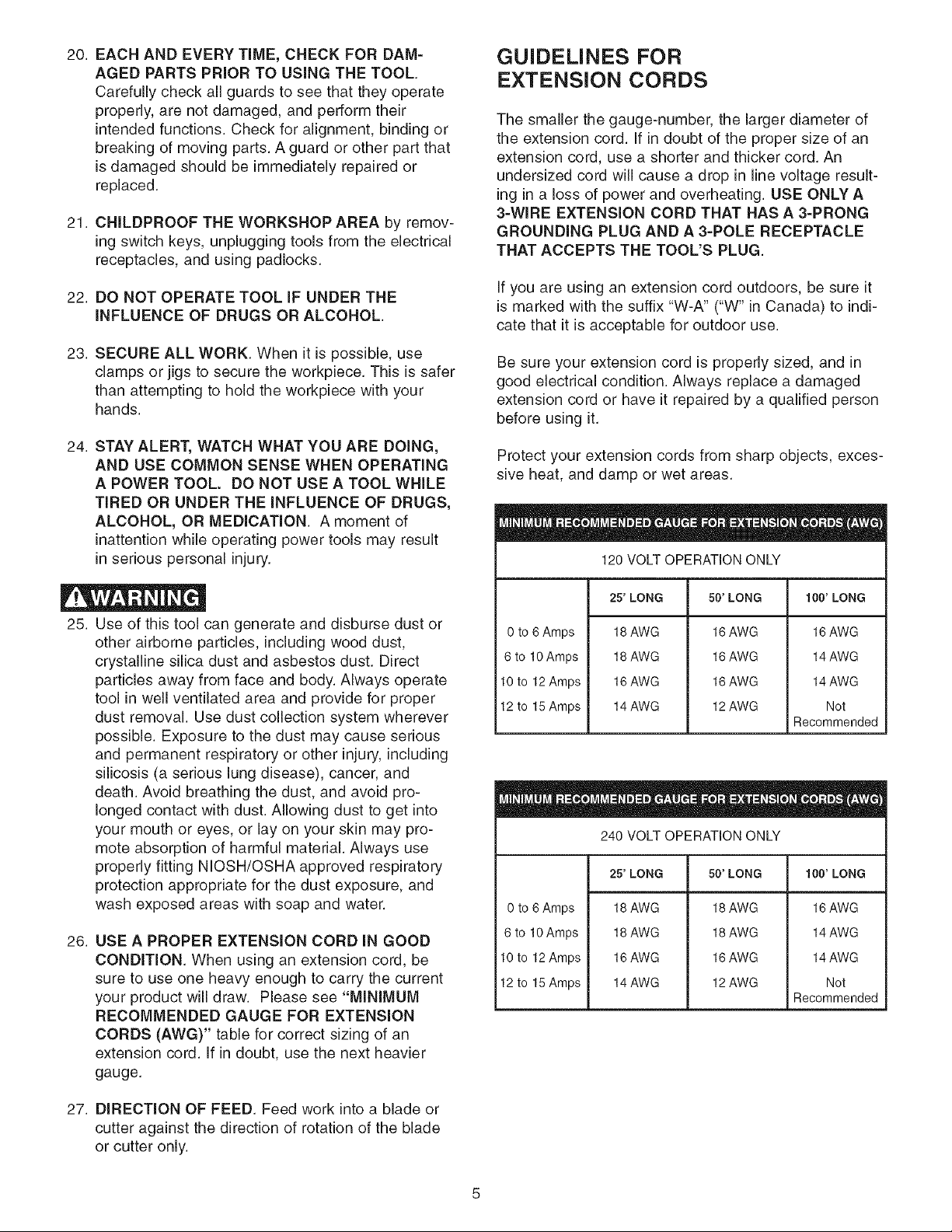
This tool is intended for use on a circuit that has an
electrical receptacle as shown in FIGURE "IA'.
FIGURE "IA" shows a 3-wire electrical plug and elec-
trical receptacle that has a grounding conductor. If a
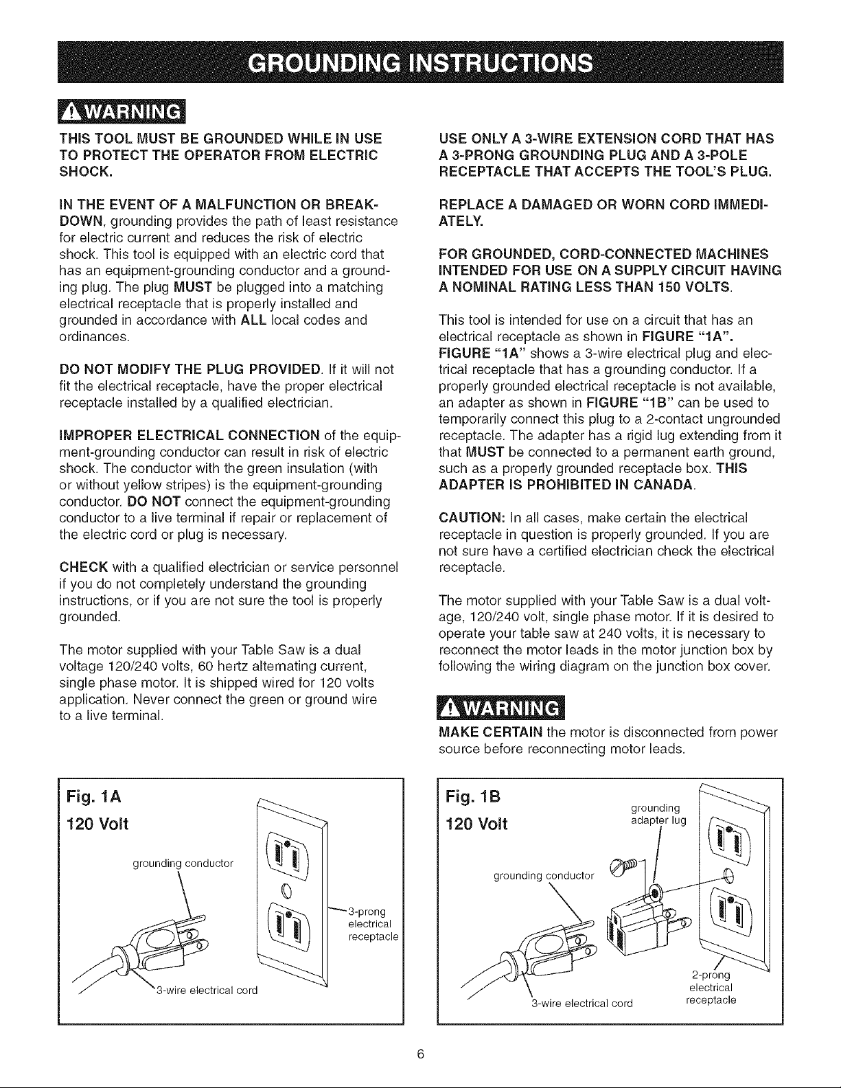
properly grounded electrical receptacle is not available,
an adapter as shown in FIGURE "IB" can be used to
temporarily connect this plug to a 2-contact ungrounded
receptacle. The adapter has a rigid lug extending from it
that MUST be connected to a permanent earth ground,
such as a properly grounded receptacle box. THIS
ADAPTER IS PROHiBiTED iN CANADA.
CAUTION: In all cases, make certain the electrical
receptacle in question is properly grounded. If you are
not sure have a certified electrician check the electrical
receptacle.
The motor supplied with your Table Saw is a dual volt-
age, 120/240 volt, single phase motor. If it is desired to
operate your table saw at 240 volts, it is necessary to
reconnect the motor leads in the motor junction box by
following the wiring diagram on the junction box cover.
MAKE CERTAIN the motor is disconnected from power
source before reconnecting motor leads.
Fig. 1A
120 Volt
grounding conductor
3-wire electrical cord
Fig. 1B
grounding
120 Volt
adapter lug _
grounding conductor
0
"'_ 3-p rong
electrical
receptacle
2-prong
electrical
3-wire electrical cord
receptacle
It is also necessary to replace the 120 volt plug, sup-
plied with the motor, with a UL/CSA Listed plug suitable
for 240 volts and rated current of the saw. Contact a
local qualified electrician for proper procedures to install
the plug. The table saw must comply with all local and
national electrical codes after the 240 volt plug is
installed.
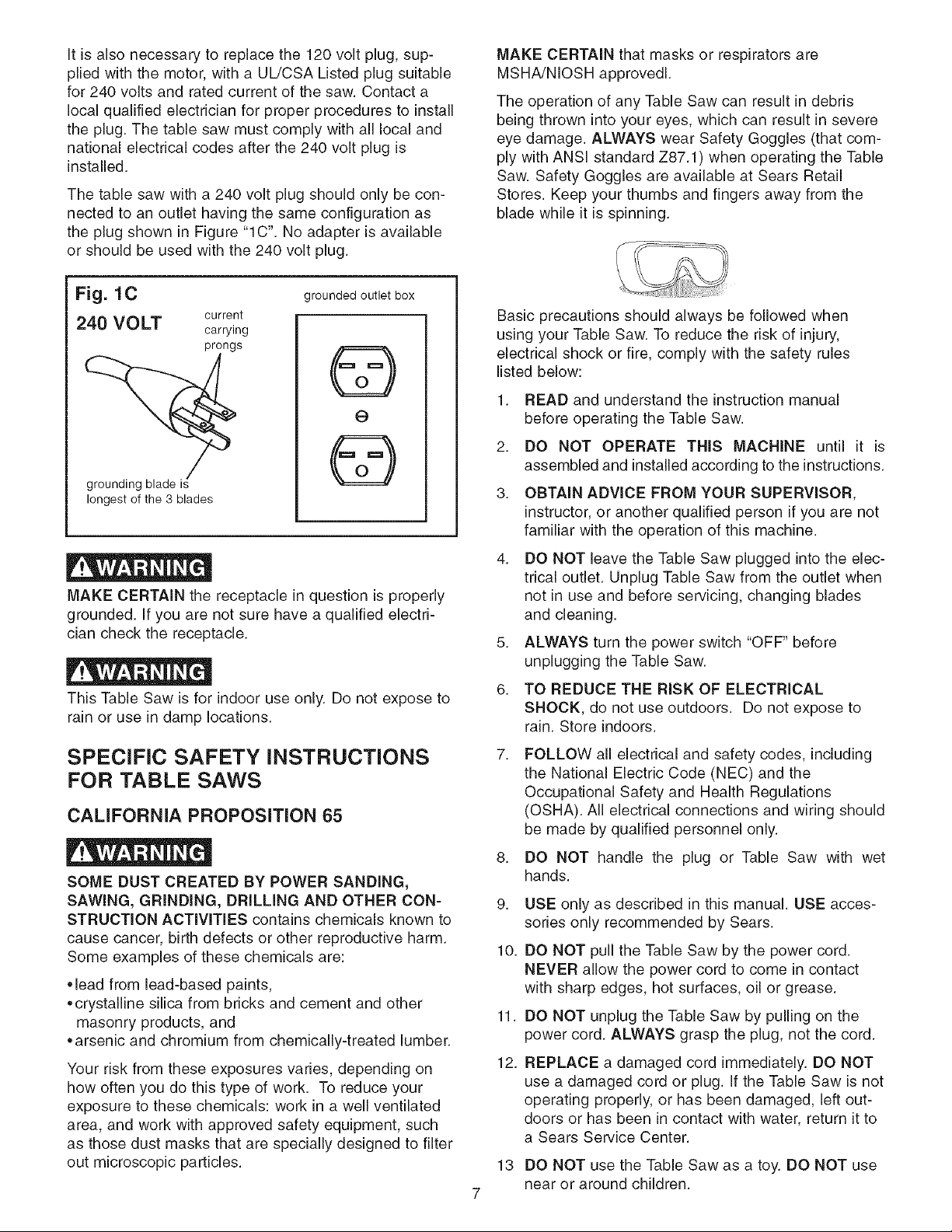
The table saw with a 240 volt plug should only be con-
nected to an outlet having the same configuration as
the plug shown in Figure "1C'. No adapter is available
or should be used with the 240 volt plug.
MAKE CERTAIN that masks or respirators are
MSHA/NIOSH approvedl.
The operation of any Table Saw can result in debris
being thrown into your eyes, which can result in severe
eye damage. ALWAYS wear Safety Goggles (that com-
ply with ANSi standard Z87.1) when operating the Table
Saw. Safety Goggles are available at Sears Retail
Stores. Keep your thumbs and fingers away from the
blade while it is spinning.
Fig. 1C
current
grounded outlet box
240 VOLT carrying
prongs
©
©
grounding blade is
longest of the 3 blades
MAKE CERTAIN the receptacle in question is properly
grounded. If you are not sure have a qualified electri-
cian check the receptacle.
This Table Saw is for indoor use only. Do not expose to
rain or use in damp locations.
Basic precautions should always be followed when
using your Table Saw. To reduce the risk of injury,
electrical shock or fire, comply with the safety rules
listed below:
1. READ and understand the instruction manual
before operating the Table Saw.
2. DO NOT OPERATE THiS MACHINE until it is
assembled and installed according to the instructions.
3. OBTAIN ADVICE FROM YOUR SUPERVISOR,
instructor, or another qualified person if you are not
familiar with the operation of this machine.
4. DO NOT leave the Table Saw plugged into the elec-
trical outlet. Unplug Table Saw from the outlet when
not in use and before servicing, changing blades
and cleaning.
5. ALWAYS turn the power switch "OFF" before
unplugging the Table Saw.
6. TO REDUCE THE RiSK OF ELECTRICAL
SHOCK, do not use outdoors. Do not expose to
rain. Store indoors.
SPECIFIC SAFETY INSTRUCTIONS
FOR TABLE SAWS
CALIFORNIA PROPOSITION 65
SOME DUST CREATED BY POWER SANDING,
SAWING, GRINDING, DRILLING AND OTHER CON=
STRUCTION ACTIVITIES contains chemicals known to
cause cancer, birth defects or other reproductive harm.
Some examples of these chemicals are:
•lead from lead-based paints,
•crystalline silica from bricks and cement and other
masonry products, and
•arsenic and chromium from chemically-treated lumber.
Your risk from these exposures varies, depending on
how often you do this type of work. To reduce your
exposure to these chemicals: work in a well ventilated
area, and work with approved safety equipment, such
as those dust masks that are specially designed to filter
out microscopic particles.
7. FOLLOW all electrical and safety codes, including
the National Electric Code (NEC) and the
Occupational Safety and Health Regulations
(OSHA). All electrical connections and wiring should
be made by qualified personnel only.
8. DO NOT handle the plug or Table Saw with wet
hands.
9. USE only as described in this manual. USE acces-
sories only recommended by Sears.
10. DO NOT pull the Table Saw by the power cord.
NEVER allow the power cord to come in contact
with sharp edges, hot surfaces, oil or grease.
11. DO NOT unplug the Table Saw by pulling on the
power cord. ALWAYS grasp the plug, not the cord.
12. REPLACE a damaged cord immediately. DO NOT
use a damaged cord or plug. If the Table Saw is not
operating properly, or has been damaged, left out-
doors or has been in contact with water, return it to
a Sears Service Center.
13 DO NOT use the Table Saw as a toy. DO NOT use
near or around children.
14.TheTableSawisdesignedforhomeuseorlight 27.NEVERperformlayout,assemblyorset-upworkon
commercialdutyONLY. thetable/workareawhenthemachineis running.
15.CONNECTTableSawtoaproperlygroundedoutlet
only.Seegroundinginstructions.
16.ALWAYSUSEtheguardswheneverpossible.
Checktoseethattheyareinplace,securedand
workingcorrectly.
17.AVOIDKICKBACKby:
" Keepingbladesharpandfreeofrustandpitch.
,,Keepingripfenceparalleltosawblade.
,, Using saw blade guard and splitter assembly for
every possible operation, including all through-
sawing.
,, Pushing the workpiece past the saw blade prior to
release.
• Never rip a workpiece that is twisted or
warped, or does not have a straight edge to guide
along the fence.
• Using featherboards when the blade guard and
splitter assembly cannot be used.
,, Never sawing a large workpiece that cannot be
controlled.
,, Never using the fence as a guide when cross-
cutting.
• Never sawing a workpiece with loose knots or
other flaws.
18. REMOVE cut-off pieces and debris from the table
before starting the saw. The vibration of the saw
may cause them to move into the saw blade and be
thrown out. After cutting, turn the saw off. When
the blade has come to a complete stop, unplug the
saw and remove all debris.
19. NEVER START the saw with the workpiece against
the blade.
20. NEVER perform "free-hand" operations. Use either
the fence or miter gauge to position and guide the
workpiece. Hold the workpiece firmly against the
miter gauge or fence.
21. USE a push stick(s) for ripping a narrow workpiece.
22. AVOID AWKWARD OPERATIONS AND HAND
POSiTiONS where a sudden slip could cause a
hand to move into the blade.
23. KEEP arms, hands and fingers away from the blade.
24. NEVER have any part of your body in line with the
path of the saw blade.
25. NEVER reach around or over the blade.
26. NEVER attempt to free a stalled blade without first
turning the machine "OFF" and unplugging it from
the power source.
28.
NEVER reset the thermal-overload button before
you have turned the table saw "OFF".
29.
PROPERLY SUPPORT long or wide workpiece.
30.
TURN THE SAW "OFF" and unplug from power
source. Clean off the table/work area before leav-
ing the saw. LOCK the START/STOP switch with
padlock provided to prevent unauthorized use.
31.
ALWAYS position auxiliary fence at least 2-inches
in front of saw blade when using auxiliary fence as
a stop when cross cutting.
32.
The right extension wing MUST BE completely
assembled and motor cover closed and fastened
before table saw is to be connected to the power
source.
33.
ADDITIONAL INFORMATION regarding the safe
and proper operation of this product is available
from the National Safety Council, 1121 Spring Lake
Drive, Itasca, IL 60143-3201 in the Accident
Prevention Manual for Industrial Operation and also
in the Safety Data Sheets provided by the NSC.
Please also refer to the American National
Standards Institute ANSI 01.1 Safety Requirements
for Woodworking Machinery and the U.S.
Department of Labor OSHA 1910.213 Regulations.
34.
SAVE THESE INSTRUCTIONS. Refer to them
frequently and use them to instruct other users.
information regarding the safe and proper operation of
this tool is available from the following sources:
Power Tool Institute
1300 Summer Avenue
Cleveland, OH 44115-2851
www.powertoolinstitute.org
National Safety Council
1121 Spring Lake Drive
Itasca, IL 60143-3201
American National Standards institute
25 West 43rd Street
4th floor
New York, NY 10036
www.ansi.org
ANSi 01.1 Safety Requirements for Woodworking\
Machines, and the U.S. Department of Labor regulations
www.osha.gov
AVAILABLE ACCESSORIES
Visit your Sears Hardware Department or see the Sears
Power and Hand Tool Catalog for the following acces-
sories.
ITEM STOCK NUMBER
* Auxiliary Fence, Rip Fence 29878
* Miter Gauge Extension & Stop 29879
* Stock Clamp, Miter Gauge 29880
* Dust Chute with Dust Port 22102
* Micro-Adjustment Assembly 29881
* Table Insert - Standard 29882
* Table Insert - Dado 29885
* Table Insert - Molding Cutterhead 29887
* Saw Blade - Leitz, 10-in. x 40 tooth 29888
variable pitch blade
* Fence Guide System 32371
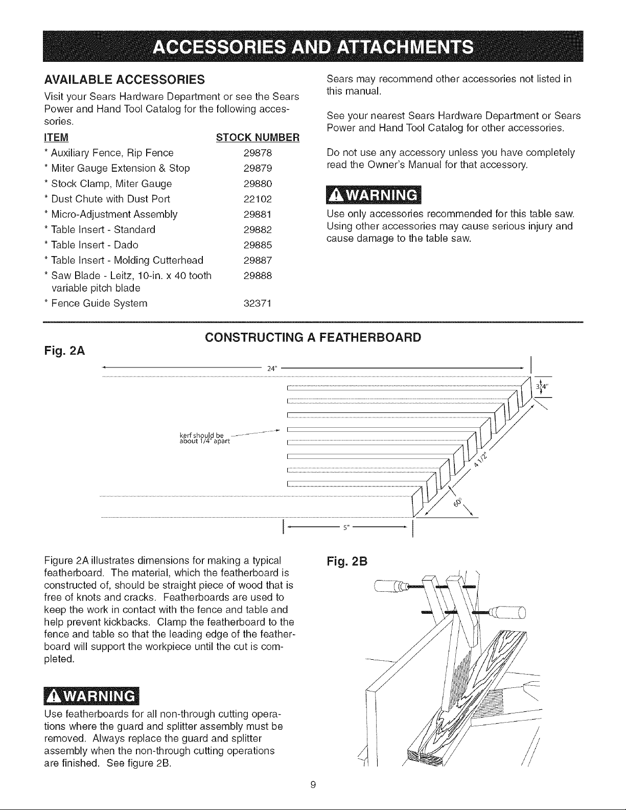
CONSTRUCTING A FEATHERBOARD
Fig. 2A
24"
Sears may recommend other accessories not listed in
this manual.
See your nearest Sears Hardware Department or Sears
Power and Hand Tool Catalog for other accessories.
Do not use any accessory unless you have completely
read the Owner's Manual for that accessory.
Use only accessories recommended for this table saw.
Using other accessories may cause serious injury and
cause damage to the table saw.
Figure 2A illustrates dimensions for making a typical
featherboard. The material, which the featherboard is
constructed of, should be straight piece of wood that is
free of knots and cracks. Featherboards are used to
keep the work in contact with the fence and table and
help prevent kickbacks. Clamp the featherboard to the
fence and table so that the leading edge of the feather-
board will support the workpiece until the cut is com-
pleted.
Use featherboards for all non-through cutting opera-
tions where the guard and splitter assembly must be
removed. Always replace the guard and splitter
assembly when the non-through cutting operations
are finished. See figure 2B.
5"
Fig. 2B
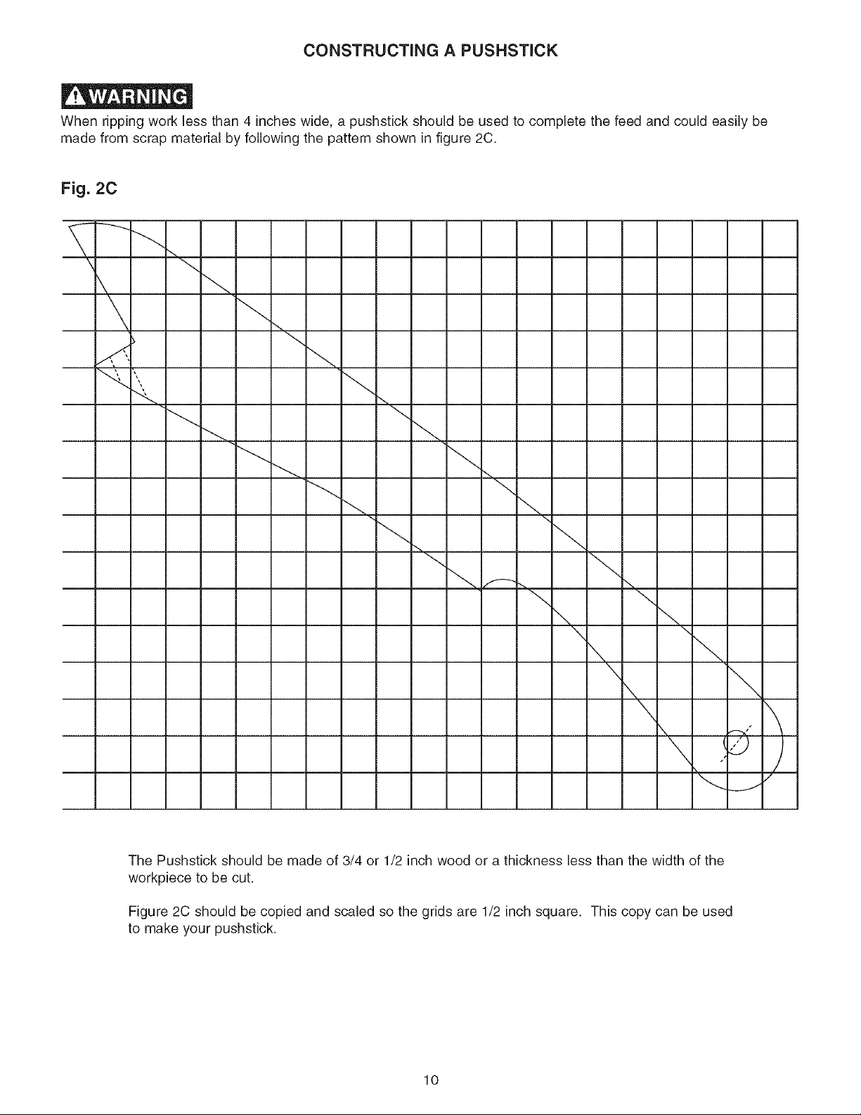
CONSTRUCTING A PUSHSTICK
When ripping work less than 4 inches wide, a pushstick should be used to complete the feed and could easily be
made from scrap material by following the pattern shown in figure 2C.
Fig. 2C
The Pushstick should be made of 3/4 or 1/2 inch wood or a thickness less than the width of the
workpiece to be cut.
Figure 2C should be copied and scaled so the grids are 1/2 inch square. This copy can be used
to make your pushstick.
10
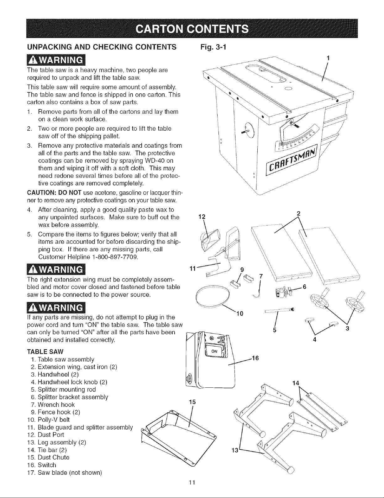
UNPACKING AND CHECKING CONTENTS
The table saw is a heavy machine, two people are
required to unpack and lift the table saw.
This table saw will require some amount of assembly.
The table saw and fence is shipped in one carton. This
carton also contains a box of saw parts.
1. Remove parts from all of the cartons and lay them
on a clean work surface.
2. Two or more people are required to lift the table
saw off of the shipping pallet.
3. Remove any protective materials and coatings from
all of the parts and the table saw. The protective
coatings can be removed by spraying WD-40 on
them and wiping it off with a soft cloth. This may
need redone several times before all of the protec-
tive coatings are removed completely.
CAUTION: DO NOT use acetone, gasoline or lacquer thin-
ner to remove any protective coatings on your table saw.
4. After cleaning, apply a good quality paste wax to
any unpainted surfaces. Make sure to buff out the
wax before assembly.
5. Compare the items to figures below; verify that all
items are accounted for before discarding the ship-
ping box. If there are any missing parts, call
Customer Helpline 1-800-897-7709.
The right extension wing must be completely assem-
bled and motor cover closed and fastened before table
saw is to be connected to the power source.
12
11
Fig. 3=1
\
\
o
\ o
\
2
\
\
\
\
\
\
\
\
\
\
\
\
\
\
\
\
\
If any parts are missing, do not attempt to plug in the
power cord and turn "ON" the table saw. The table saw
can only be turned "ON" after all the parts have been
obtained and installed correctly.
TABLE SAW
1. Table saw assembly
2. Extension wing, cast iron (2)
3. Handwheel (2)
4. Handwheel lock knob (2)
5. Splitter mounting rod
6. Splitter bracket assembly
7. Wrench hook
9. Fence hook (2)
10. Polly-V belt
11. Blade guard and splitter assembly
12. Dust Port
13. Leg assembly (2)
14. Tie bar (2)
15. Dust Chute
16. Switch
17. Saw blade (not shown)
10
14
15
11
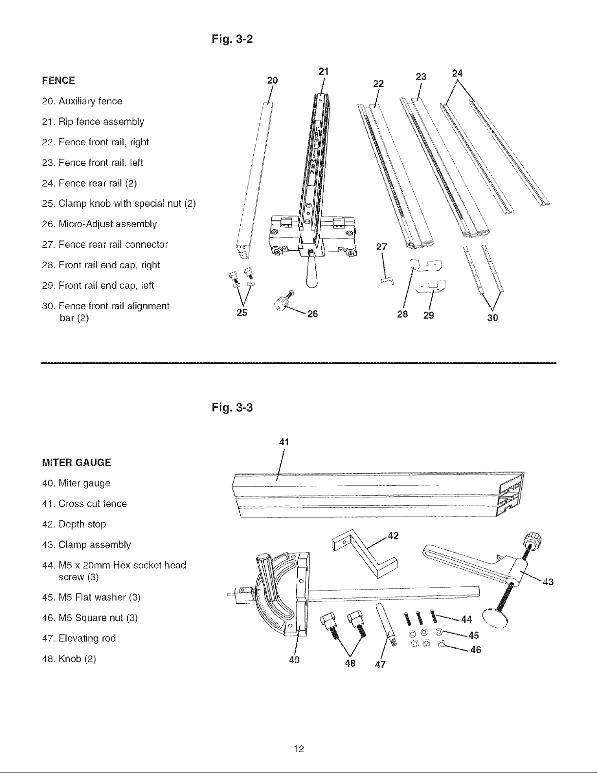
Fig. 3=2
FENCE
20. Auxiliary fence
21. Rip fence assembly
22. Fence front rail, right
23. Fence front rail, left
24. Fence rear rail (2)
25. Clamp knob with special nut (2)
26. Micro-Adjust assembly
27. Fence rear rail connector
28. Front rail end cap, right
29. Front rail end cap, left
30. Fence front rail alignment
bar (2)
25
2O
21
22
27
23 24
28 29
3O
MITER GAUGE
40. Miter gauge
41. Cross cut fence
42. Depth stop
43. Clamp assembly
44. M5 x 20mm Hex socket head
screw (3)
45. M5 Flat washer (3)
46. M5 Square nut (3)
47. Elevating rod
48. Knob (2)
Fig. 3=3
41
12
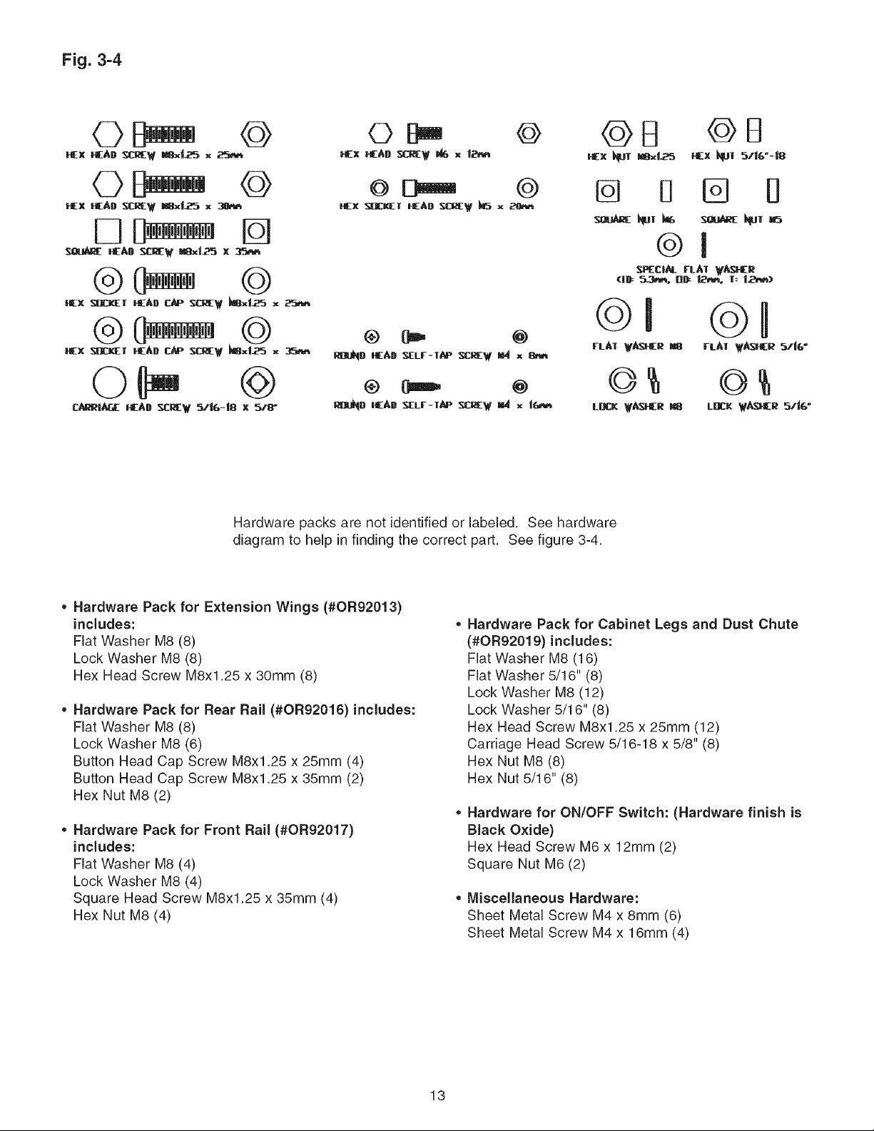
Fig. 3-4
GB
GX GAD _W _'_ x t_'_
@
Gx SDC_T GAB _RE W _ x
@
_ci_ rL^l ¥_r
@ Ore, @
RInD GAD _Lr-W_ _W _ x
@ 0===_ @
_D GAD_Lr-l._ _I w _ _ 1_',_
Hardware packs are not identified or labeled. See hardware
diagram to help in finding the correct part. See figure 3-4.
• Hardware Pack for Extension Wings (#0R92013)
includes:
Flat Washer M8 (8)
Lock Washer M8 (8)
Hex Head Screw M8x1.25 x 30mm (8)
• Hardware Pack for Rear Rail (#0R92016) includes:
Flat Washer M8 (8)
Lock Washer M8 (6)
Button Head Cap Screw M8x1.25 x 25mm (4)
Button Head Cap Screw M8x1.25 x 35mm (2)
Hex Nut M8 (2)
* Hardware Pack for Front Rail (#0R92017)
includes:
Flat Washer M8 (4)
Lock Washer M8 (4)
Square Head Screw M8x1.25 x 35mm (4)
Hex Nut M8 (4)
©I ©I
L_ _f_ _ LDL__e _i_"
Hardware Pack for Cabinet Legs and Dust Chute
(#0R92019) includes:
Flat Washer M8 (16)
Flat Washer 5/16" (8)
Lock Washer M8 (12)
Lock Washer 5/16" (8)
Hex Head Screw M8x1.25 x 25ram (12)
Carriage Head Screw 5/16-18 x 5/8" (8)
Hex Nut M8 (8)
Hex Nut 5/16" (8)
Hardware for ON/OFF Switch: (Hardware finish is
Black Oxide)
Hex Head Screw M6 x 12mm (2)
Square Nut M6 (2)
* Miscellaneous Hardware:
Sheet Metal Screw M4 x 8mm (6)
Sheet Metal Screw M4 x 16mm (4)
13
25
26
22
23
27 2
5 4
1
3 9
8
6 7 11
10
12
13
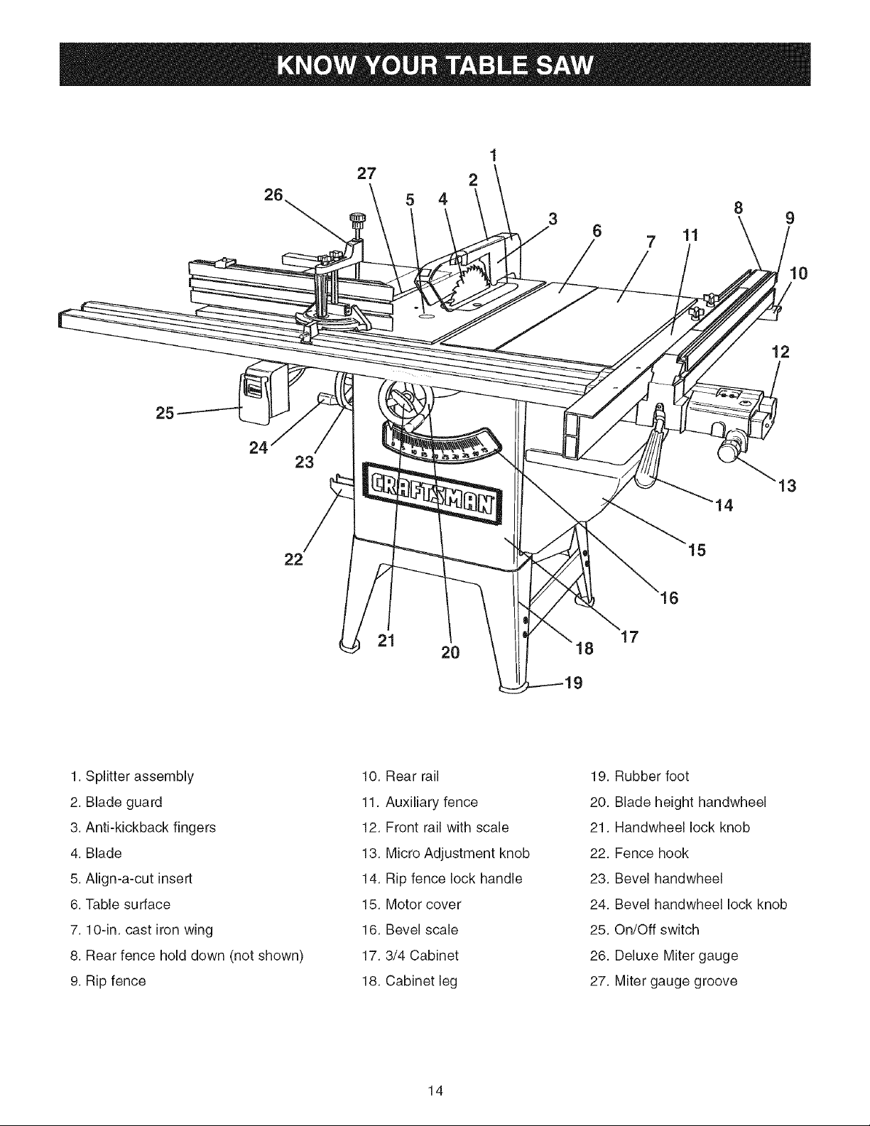
1. Splitter assembly
2. Blade guard
3. Anti-kickback fingers
4. Blade
5. Align-a-cut insert
6. Table surface
7. lO-in, cast iron wing
8. Rear fence hold down (not shown)
9. Rip fence
21 17
2O B
10. Rear rail
11. Auxiliary fence
12. Front rail with scale
13. Micro Adjustment knob
14. Rip fence lock handle
15. Motor cover
16. Bevel scale
17.3/4 Cabinet
18. Cabinet leg
19. Rubber foot
20. Blade height handwheel
21. Handwheel lock knob
22. Fence hook
23. Bevel handwheel
24. Bevel handwheel lock knob
25. On/Off switch
26. Deluxe Miter gauge
27. Miter gauge groove
14
TOOLS REQUIRED
The following tools are needed for assembly and align-
ment. Note: Two blade wrenches and five hex wrenches
are provided with your table saw. The remaining tools
are typical shop tools and are not included with your
table saw.
18mm wrench 8mm wrench
13mm wrench 3/16-in. hex wrench
10mm wrench #2 Phillips screwdriver
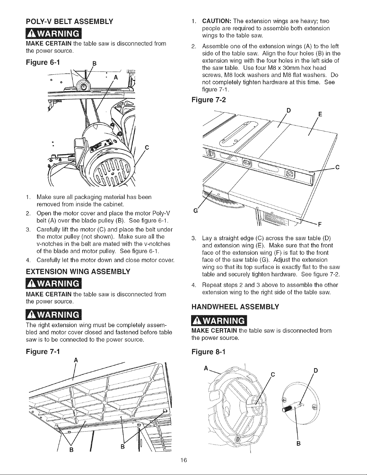
3,
Attach two tie bars (F) inside and between front and
rear legs already attached to the cabinet with (G)
eight 5/16-18 x 5/8" carriage head screws, 5/16" flat
washers, 5/16" lock washers and 5/16-18 hex nuts
and securely tighten all hardware. See figure 4-1.
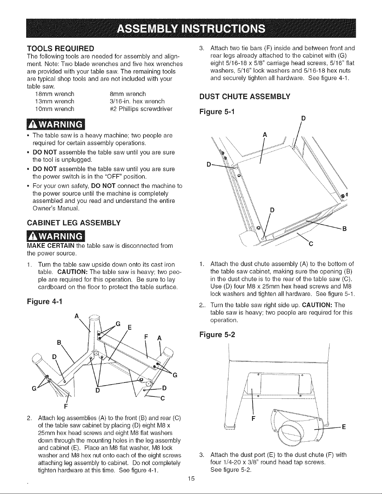
DUST CHUTE ASSEMBLY
Figure 5=1
D
• The table saw is a heavy machine; two people are
required for certain assembly operations.
• DO NOT assemble the table saw until you are sure
the tool is unplugged.
• DO NOT assemble the table saw until you are sure
the power switch is in the "OFF" position.
• For your own safety, DO NOT connect the machine to
the power source until the machine is completely
assembled and you read and understand the entire
Owner's Manual.
CABINET LEG ASSEMBLY
MAKE CERTAIN the table saw is disconnected from
the power source.
1. Turn the table saw upside down onto its cast iron
table. CAUTION: The table saw is heavy; two peo-
ple are required for this operation. Be sure to lay
cardboard on the floor to protect the table surface.
Figure 4=1
A
E
F A
A
B
C
1. Attach the dust chute assembly (A) to the bottom of
the table saw cabinet, making sure the opening (B)
in the dust chute is to the rear of the table saw (C).
Use (D) four M8 x 25mm hex head screws and M8
lock washers and tighten all hardware. See figure 5-1.
2.. Turn the table saw right side up. CAUTION: The
table saw is heavy; two people are required for this
operation.
Figure 5=2
D
2,
Attach leg assemblies (A) to the front (B) and rear (C)
of the table saw cabinet by placing (D) eight M8 x
25ram hex head screws and eight M8 flat washers
down through the mounting holes in the leg assembly
and cabinet (E). Place an M8 flat washer, M8 lock
washer and M8 hex nut onto each of the eight screws
attaching leg assembly to cabinet. Do not completely
tighten hardware at this time. See figure 4-1.
_E
3. Attach the dust port (E) to the dust chute (F) with
four 1/4-20 x 3/8" round head tap screws.
See figure 5-2.
15
POLY=V BELT ASSEMBLY
MAKE CERTAIN the table saw is disconnected from
the power source.
Figure 64
J
A
o
- c
/4
1.
CAUTION: The extension wings are heavy; two
people are required to assemble both extension
wings to the table saw.
2.
Assemble one of the extension wings (A) to the left
side of the table saw. Align the four holes (B) in the
extension wing with the four holes in the left side of
the saw table. Use four M8 x 30mm hex head
screws, M8 lock washers and M8 flat washers. Do
not completely tighten hardware at this time. See
figure 7-1.
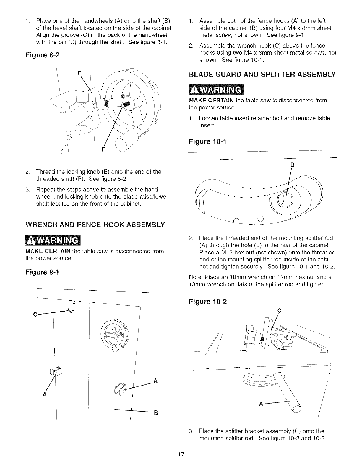
Figure 7=2
D
E
1. Make sure all packaging material has been
removed from inside the cabinet.
2. Open the motor cover and place the motor Poly-V
belt (A) over the blade pulley (B). See figure 6-1.
3. Carefully lift the motor (C) and place the belt under
the motor pulley (not shown). Make sure all the
v-notches in the belt are mated with the v-notches
of the blade and motor pulley. See figure 6-1.
4. Carefully let the motor down and close motor cover.
EXTENSION WING ASSEMBLY
MAKE CERTAIN the table saw is disconnected from
the power source.
The right extension wing must be completely assem-
bled and motor cover closed and fastened before table
saw is to be connected to the power source.
Figure 74
A
3. Lay a straight edge (C) across the saw table (D)
and extension wing (E). Make sure that the front
face of the extension wing (F) is flat to the front
face of the saw table (G). Adjust the extension
wing so that its top surface is exactly flat to the saw
table and securely tighten hardware. See figure 7-2.
4. Repeat steps 2 and 3 above to assemble the other
extension wing to the right side of the table saw.
HANDWHEEL ASSEMBLY
MAKE CERTAIN the table saw is disconnected from
the power source.
Figure 8-1
C
D
16
B
Placeoneofthehandwheels(A)ontotheshaft(B)
ofthebevelshaftlocatedonthesideofthecabinet.
Alignthegroove(C)inthebackofthehandwhee[
withthepin(D)throughtheshaft.Seefigure8-1.
Figure 8=2
1. Assemble both of the fence hooks (A) to the left
side of the cabinet (B) using four M4 x 8mm sheet
metal screw, not shown. See figure 9-1.
2. Assemble the wrench hook (C) above the fence
hooks using two M4 x 8mm sheet metal screws, not
shown. See figure 10-1.
E
2. Thread the locking knob (E) onto the end of the
threaded shaft (F). See figure 8-2.
3. Repeat the steps above to assemble the hand-
wheel and locking knob onto the blade raise/lower
shaft located on the front of the cabinet.
WRENCH AND FENCE HOOK ASSEMBLY
MAKE CERTAIN the table saw is disconnected from
the power source.
Figure 94
BLADE GUARD AND SPLITTER ASSEMBLY
MAKE CERTAIN the table saw is disconnected from
the power source.
1. Loosen table insert retainer bolt and remove tame
insert.
Figure 10=1
B
2. Place the threaded end of the mounting splitter rod
(A) through the hole (B) in the rear of the cabinet.
Place a M12 hex nut (not shown) onto the threaded
end of the mounting splitter rod inside of the cabi-
net and tighten securely. See figure 10-1 and 10-2.
Note: Place an 18mm wrench on 12mm hex nut and a
13mm wrench on flats of the splitter rod and tighten.
Figure 10=2
C
/
A
3. Place the splitter bracket assembly (C) onto the
mounting splitter rod. See figure 10-2 and 10-3.
17
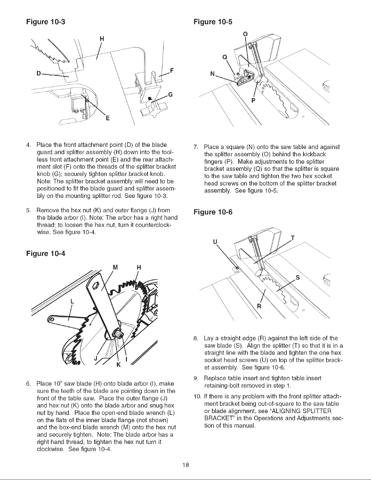
Figure 10=3
Figure 10=5
H
\
4,
Place the front attachment point (D) of the blade
guard and splitter assembly (H) down into the tool-
less front attachment point (E) and the rear attach-
ment slot (F) onto the threads of the splitter bracket
knob (G); securely tighten splitter bracket knob.
Note: The splitter bracket assembly will need to be
positioned to fit the blade guard and splitter assem-
bly on the mounting splitter rod. See figure 10-3.
0
Q
7,
Place a square (N) onto the saw table and against
the splitter assembly (0) behind the kickback
fingers (P). Make adjustments to the splitter
bracket assembly (Q) so that the splitter is square
to the saw table and tighten the two hex socket
head screws on the bottom of the splitter bracket
assembly. See figure 10-5.
5,
Remove the hex nut (K) and outer flange (J) from
the blade arbor (I). Note: The arbor has a right hand
thread; to loosen the hex nut, turn it counterclock-
wise. See figure 10-4.
Figure 10=4
M
6,
Place 10" saw blade (H) onto blade arbor (I), make
sure the teeth of the blade are pointing down in the
front of the table saw. Place the outer flange (J)
and hex nut (K) onto the blade arbor and snug hex
nut by hand. Place the open-end blade wrench (L)
on the flats of the inner blade flange (not shown)
and the box-end blade wrench (M) onto the hex nut
and securely tighten. Note: The blade arbor has a
right hand thread, to tighten the hex nut turn it
clockwise. See figure 10-4.
Figure 10=6
U
8. Lay a straight edge (R) against the left side of the
saw blade (S). Align the splitter (T) so that it is in a
straight line with the blade and tighten the one hex
socket head screws (U) on top of the splitter brack-
et assembly. See figure 10-6.
9. Replace table insert and tighten table insert
retaining-bolt removed in step 1.
10. If there is any problem with the front splitter attach-
ment bracket being out-of-square to the saw table
or blade alignment, see "AMGNING SPMTTER
BRACKET" in the Operations and Adjustments sec-
tion of this manual.
18
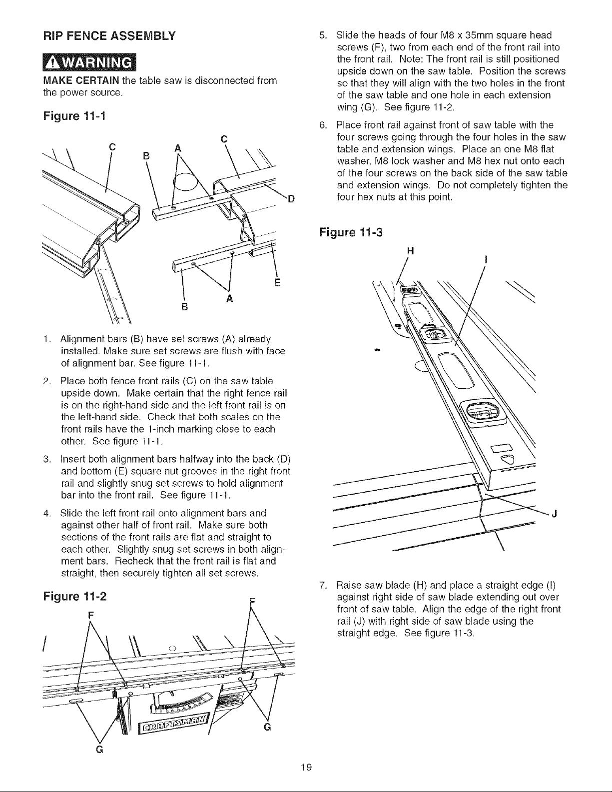
RiP FENCE ASSEMBLY
MAKE CERTAIN the table saw is disconnected from
the power source.
Figure 11-1
C
A
B
C
A
5. Slide the heads of four M8 x 35mm square head
screws (F), two from each end of the front rail into
the front rail. Note: The front rail is still positioned
upside down on the saw table. Position the screws
so that they will align with the two holes in the front
of the saw table and one hole in each extension
wing (G). See figure 11-2.
6. Place front rail against front of saw table with the
four screws going through the four holes in the saw
table and extension wings. Place an one M8 flat
washer, M8 lock washer and M8 hex nut onto each
of the four screws on the back side of the saw table
and extension wings. Do not completely tighten the
"D
four hex nuts at this point.
Figure 11=3
H
E
1. Alignment bars (B) have set screws (A) already
installed. Make sure set screws are flush with face
of alignment bar. See figure 11-1.
2. Place both fence front rails (C) on the saw table
upside down. Make certain that the right fence rail
is on the right-hand side and the left front rail is on
the left-hand side. Check that both scales on the
front rails have the 1-inch marking close to each
other. See figure 11-1.
3. Insert both alignment bars halfway into the back (D)
and bottom (E) square nut grooves in the right front
rail and slightly snug set screws to hold alignment
bar into the front rail. See figure 11-1.
4. Slide the left front rail onto alignment bars and
against other half of front rail. Make sure both
sections of the front rails are flat and straight to
each other. Slightly snug set screws in both align-
ment bars. Recheck that the front rail is flat and
straight, then securely tighten all set screws.
Figure 11=2
F
O
7,
Raise saw blade (H) and place a straight edge (I)
against right side of saw blade extending out over
front of saw table. Align the edge of the right front
rail (J) with right side of saw blade using the
straight edge. See figure 11-3.
G
G
19

Figure 11=4
K
8.
Using a combination square (K), make sure the
front rail (L) is level across the saw table and exten-
sion wings, and then securely tighten the four hex
nuts. See figure 11-4.
Figure 11=5
M
Figure 11=6
R
11. Slide the right side rear rail (T) onto rear rail con-
nector. Assemble the right rear rail with two M8 x
25mm button head cap screws to the saw table and
one M8 x 35mm button head cap screw, M8 flat
washer, M8 lock washer and M8 hex nut to the
extension wing. See figure 11-6.
12. Using a combination square, make sure the rear rail
is level to the saw table and extension wings and
below the bottom of the miter gauge slots, then
securely tighten all hardware. See figure 11-4.
Figure 11=7
AC
U
Y
Z
/
0
9.
Assemble the left side rear rail (M) to the left rear
side of the table saw (N). Attach rear rail (M) to
table (N) with two M8 x 25mm button head cap
screws, M8 Iockwashers, and M8 flat washers (0).
Attach rear rail to extension wing with one M8 x
35mm button head cap screw, M8 flat washer, M8
Iockwasher and M8 hex nut (P). Make sure that
the rear rail is below the bottom of the miter gauge
slots (R) in the saw table. See figure 11-5 and
11-6.
10.
Slide rear rail connector (S) into the left rear rail
already assembled. See figure 11-5.
Q
13. Assemble the two cursors (U) to the rip fence
assembly (V) using four M5 x 16mm pan head
screws and M5 lock washers (W). See figure 11-7.
14. Lift up on the rip fence handle (X) and place the
fence down onto the saw table with the fence body
intofront rail. With the rip fence lock handle up, you
can slide the fence back and forth across the saw
table. Pushing the rip fence lock handle down will
lock the fence from moving. See figure 11-7.
15. Align left fence side (AB) at a distance from the
right side (AC) of the right miter gauge groove and
lock the fence. See figure 11-7.
16.
Use a measuring tape to measure the distance from
the saw blade right side to the left fence side.
20
W
V
17.Assemblethecursor(U)totherightsideoffence
crossarmwithtwoM5x16mmpanheadscrews
andM5lockwashers(W).Donotcompletelytight-
enscrews.Seefigure11-7.
18.Aligncursorwiththescale(Z)sothatthethinblack
line(Y)isonthesamenumberasthedistance
measuredinstep16.Tightenthecursorscrews.
19.Removefencefromtableandrepositionitonleft
sideofsawblade.Alignrightfencesideatadis-
tancefromtheleftsideofleftmitergaugegroove
andlockthefence.
20.Useameasuringtapetomeasurethedistancefrom
thesawbladeleftsidetotherightfenceside.
21.Assemblethesecondcursorto leftsideoffence
crossarmwithtwoM5x16mmpanheadscrews
andM6lockwashers.Donotcompletelytighten
screws.
22.Aligncursorwiththescalesothatthethinblackline
isonthesamenumberasthedistancemeasuredin
step20.Tightenthecursorscrews.
Figure 11=8
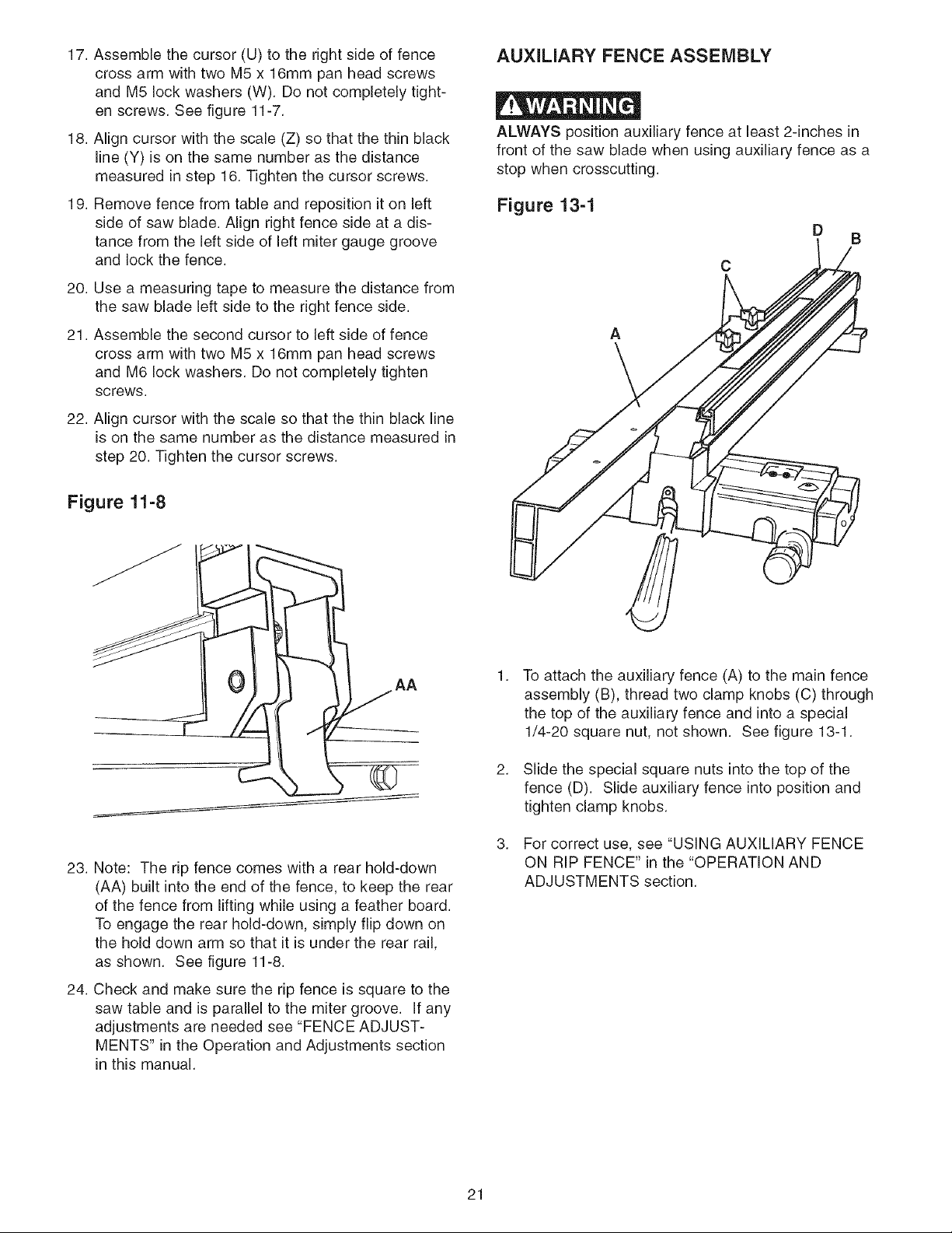
AUXILIARY FENCE ASSEMBLY
ALWAYS position auxiliary fence at least 2-inches in
front of the saw blade when using auxiliary fence as a
stop when crosscutting.
Figure 13=1
D
B
A
AA
23. Note: The rip fence comes with a rear hold-down
(AA) built into the end of the fence, to keep the rear
of the fence from lifting while using a feather board.
To engage the rear hold-down, simply flip down on
the hold down arm so that it is under the rear rail,
as shown. See figure 11-8.
24. Check and make sure the rip fence is square to the
saw table and is parallel to the miter groove. If any
adjustments are needed see "FENCE ADJUST-
MENTS" in the Operation and Adjustments section
in this manual.
1,
To attach the auxiliary fence (A) to the main fence
assembly (B), thread two clamp knobs (C) through
the top of the auxiliary fence and into a special
1/4-20 square nut, not shown. See figure 13-1.
2,
Slide the special square nuts into the top of the
fence (D). Slide auxiliary fence into position and
tighten clamp knobs.
3,
For correct use, see "USING AUXILIARY FENCE
ON RIP FENCE" in the "OPERATION AND
ADJUSTMENTS section.
21
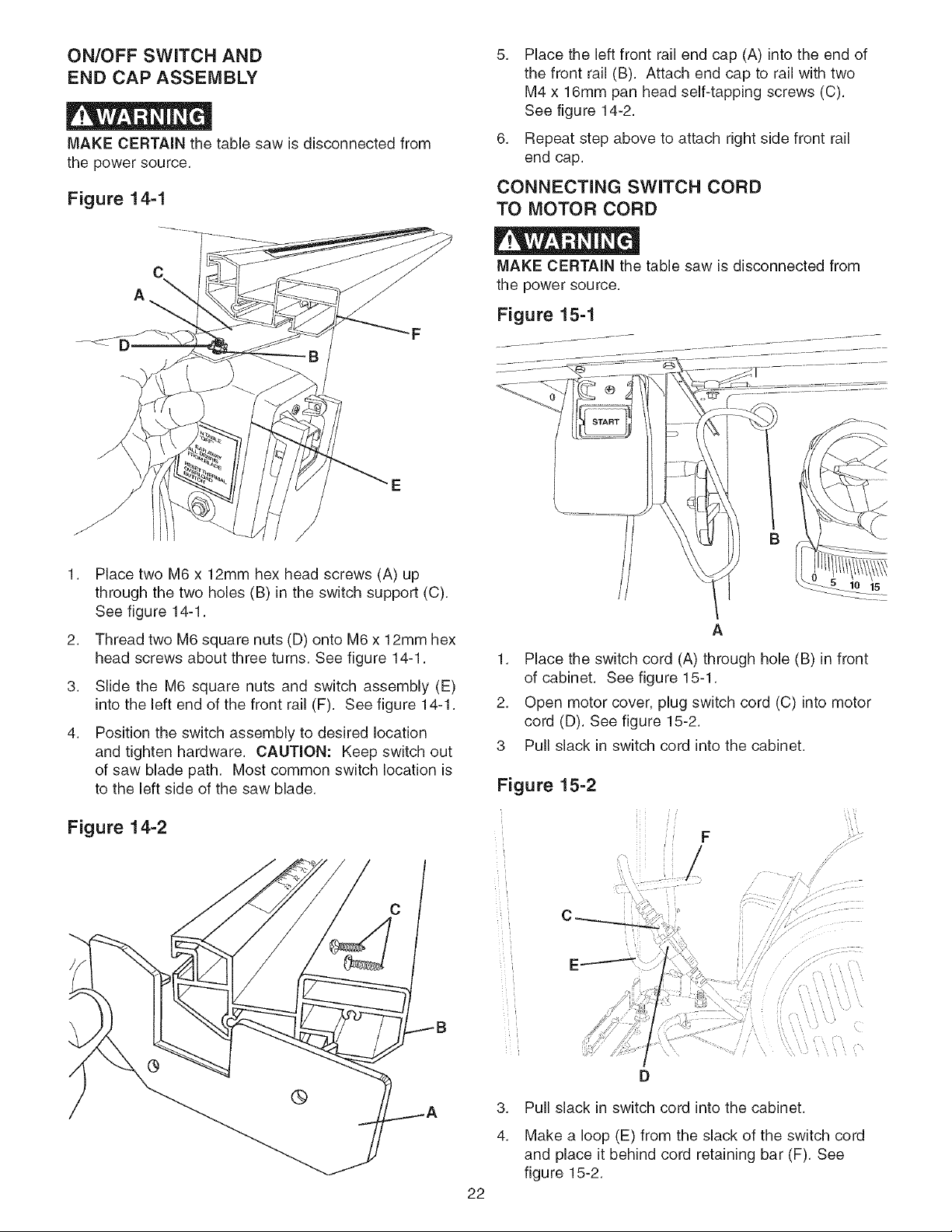
ON/OFF SWITCH AND
END CAP ASSEMBLY
MAKE CERTAIN the table saw is disconnected from
the power source.
Figure 14=1
5. Place the left front rail end cap (A) into the end of
the front rail (B). Attach end cap to rail with two
M4 x 16mm pan head self-tapping screws (C).
See figure 14-2.
6. Repeat step above to attach right side front rail
end cap.
CONNECTING SWITCH CORD
TO MOTOR CORD
MAKE CERTAIN the table saw is disconnected from
the power source.
Figure 15-1
J
J
1. Place two M6 x 12mm hex head screws (A) up
through the two holes (B) in the switch support (C).
See figure 14-1.
2. Thread two M6 square nuts (D) onto M6 x 12mm hex
head screws about three turns. See figure 14-1.
3. Slide the M6 square nuts and switch assembly (E)
into the left end of the front rail (F). See figure 14-1.
4. Position the switch assembly to desired location
and tighten hardware. CAUTION: Keep switch out
of saw blade path. Most common switch location is
to the left side of the saw blade.
Figure 14=2
C
B
A
1. Place the switch cord (A) through hole (B) in front
of cabinet. See figure 15-1.
2. Open motor cover, plug switch cord (C) into motor
cord (D). See figure 15-2.
3 Pull slack in switch cord into the cabinet.
Figure 15=2
22
D
3,
Pull slack in switch cord into the cabinet.
4.
Make a loop (E) from the slack of the switch cord
and place it behind cord retaining bar (F). See
figure 15-2.
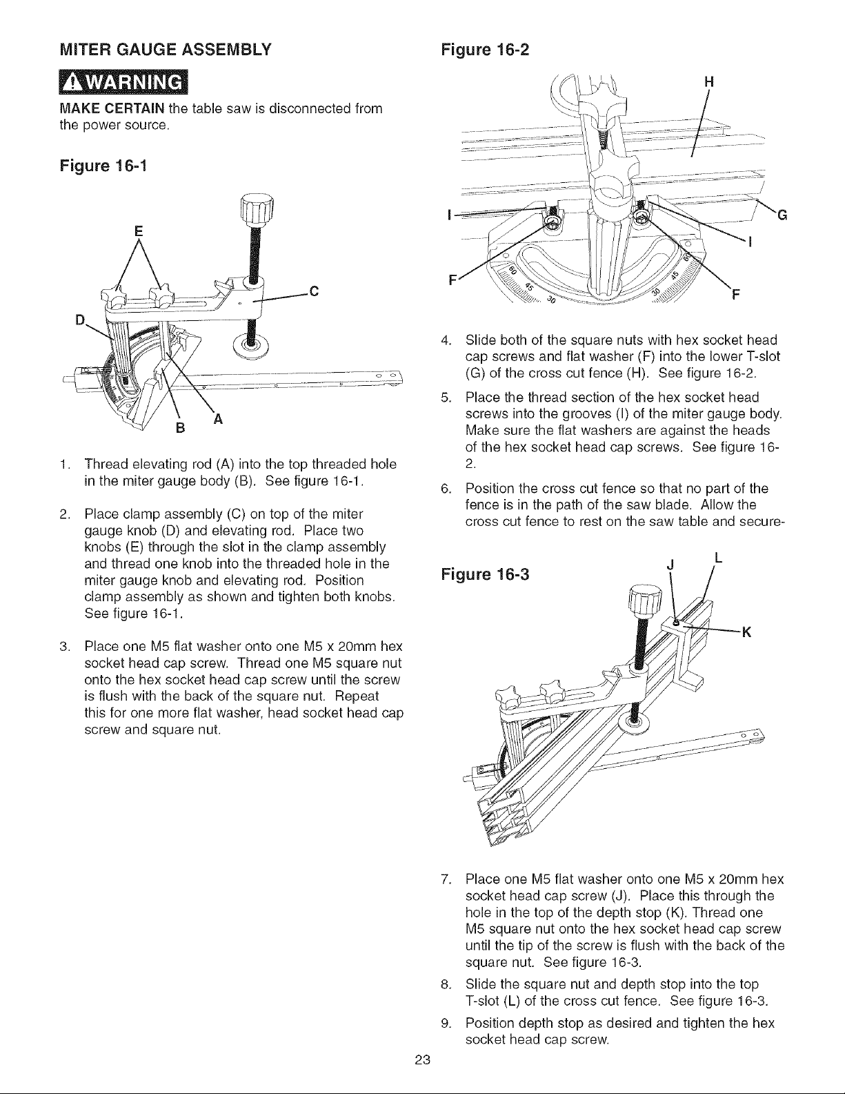
MITER GAUGE ASSEMBLY Figure 16=2
MAKE CERTAIN the table saw is disconnected from
the power source.
Figure 16=1
4. Slide both of the square nuts with hex socket head
cap screws and flat washer (F) into the lower T-slot
(G) of the cross cut fence (H). See figure 16-2.
5. Place the thread section of the hex socket head
A
B
Thread elevating rod (A) into the top threaded hole
in the miter gauge body (B). See figure 16-1.
2.
Place clamp assembly (C) on top of the miter
gauge knob (D) and elevating rod. Place two
knobs (E) through the slot in the clamp assembly
and thread one knob into the threaded hole in the
miter gauge knob and elevating rod. Position
clamp assembly as shown and tighten both knobs.
See figure 16-1.
screws into the grooves (I) of the miter gauge body.
Make sure the flat washers are against the heads
of the hex socket head cap screws. See figure 16-
2.
6.
Position the cross cut fence so that no part of the
fence is in the path of the saw blade. Allow the
cross cut fence to rest on the saw table and secure-
Figure 16=3
H
3.
Place one M5 flat washer onto one M5 x 20mm hex
socket head cap screw. Thread one M5 square nut
onto the hex socket head cap screw until the screw
is flush with the back of the square nut. Repeat
this for one more flat washer, head socket head cap
screw and square nut.
7. Place one M5 flat washer onto one M5 x 20mm hex
socket head cap screw (J). Place this through the
hole in the top of the depth stop (K). Thread one
M5 square nut onto the hex socket head cap screw
until the tip of the screw is flush with the back of the
square nut. See figure 16-3.
8. Slide the square nut and depth stop into the top
T-slot (L) of the cross cut fence. See figure 16-3.
9. Position depth stop as desired and tighten the hex
socket head cap screw.
23
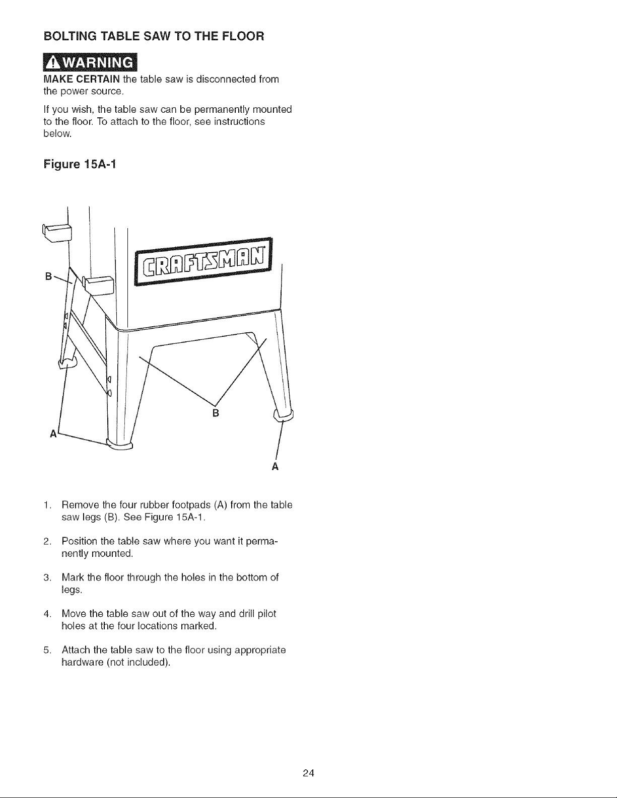
BOLTING TABLE SAW TO THE FLOOR
MAKE CERTAIN the table saw is disconnected from
the power source.
If you wish, the table saw can be permanently mounted
to the floor. To attach to the floor, see instructions
below.
Figure 15A=1
B
Remove the four rubber footpads (A) from the table
saw legs (B). See Figure 15A-1.
2,
Position the table saw where you want it perma-
nently mounted.
3,
Mark the floor through the holes in the bottom of
legs.
4,
Move the table saw out of the way and drill pilot
holes at the four locations marked.
5,
Attach the table saw to the floor using appropriate
hardware (not included).
24
CAUTION LOCKING ON/OFF SWITCH
• A separate electrical circuit should be used for your 1.
table saw. The table saw comes pre-wired for 120-volt
use. The circuit should not be less than #14 AWG wire
and should be protected with a 15-amp time lag fuse.
• Have a qualified electrician repair or replace damaged
or worn cord immediately.
• Before connecting the motor to the power line, make
certain the switch is in the "OFF" position and be sure
that the electric current is of the same characteristics 3.
as the motor nameplate. All line connections should
make good contact.
• Running on low voltage or long extension cords will
damage the motor.
• DO NOT expose the table saw to rain or operate the
in damp locations.
• MAKE SURE all parts have been assembled correctly
and are in working order.
• KEEP table surface clear of tools and debris before
starting table saw.
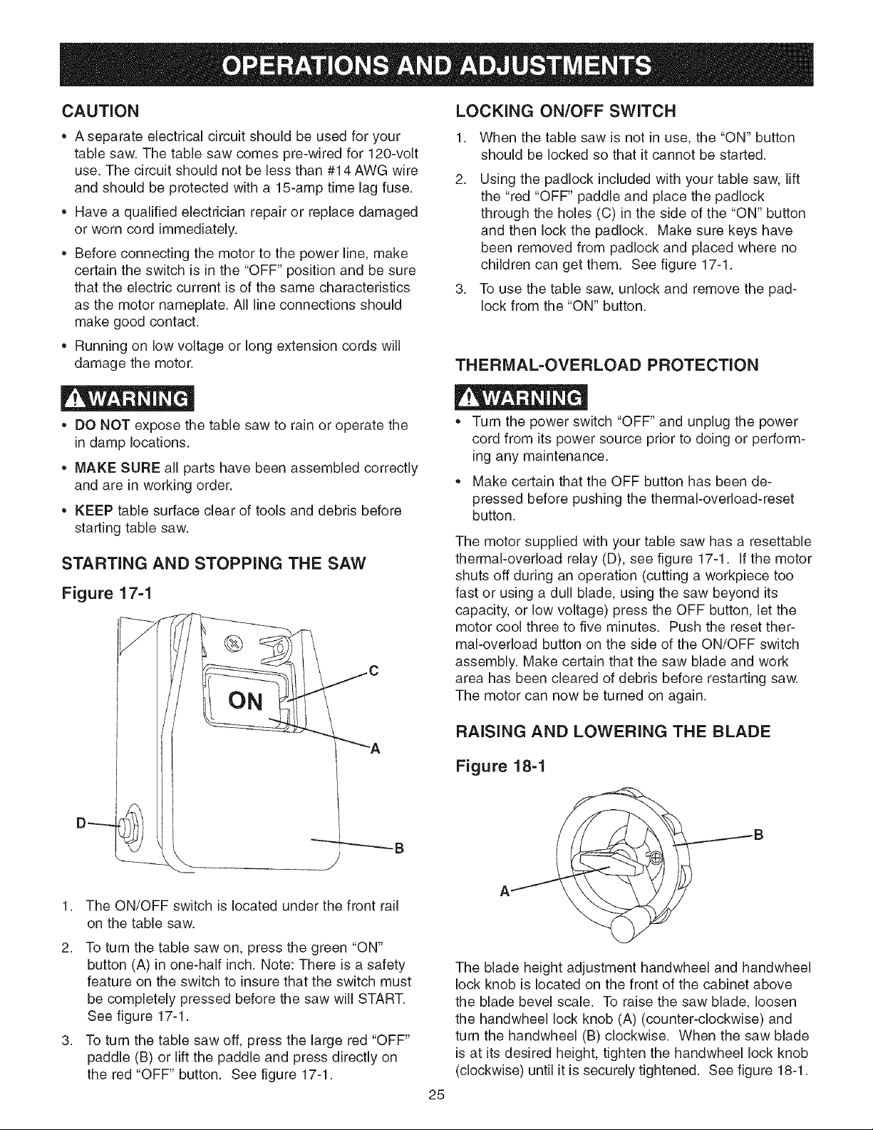
STARTING AND STOPPING THE SAW
Figure 17=1
Y
• C
L ON
A
When the table saw is not in use, the "ON" button
should be locked so that it cannot be started.
2.
Using the padlock included with your table saw, lift
the "red "OFF" paddle and place the padlock
through the holes (C) in the side of the "ON" button
and then lock the padlock. Make sure keys have
been removed from padlock and placed where no
children can get them. See figure 17-1.
To use the table saw, unlock and remove the pad-
lock from the "ON" button.
THERMAL=OVERLOAD PROTECTION
• Turn the power switch "OFF" and unplug the power
cord from its power source prior to doing or perform-
ing any maintenance.
Make certain that the OFF button has been de-
pressed before pushing the thermal-overload-reset
button.
The motor supplied with your table saw has a resettable
thermal-overload relay (D), see figure 17-1. If the motor
shuts off during an operation (cutting a workpiece too
fast or using a dull blade, using the saw beyond its
capacity, or low voltage) press the OFF button, let the
motor cool three to five minutes. Push the reset ther-
mal-overload button on the side of the ON/OFF switch
assembly. Make certain that the saw blade and work
area has been cleared of debris before restarting saw.
The motor can now be turned on again.
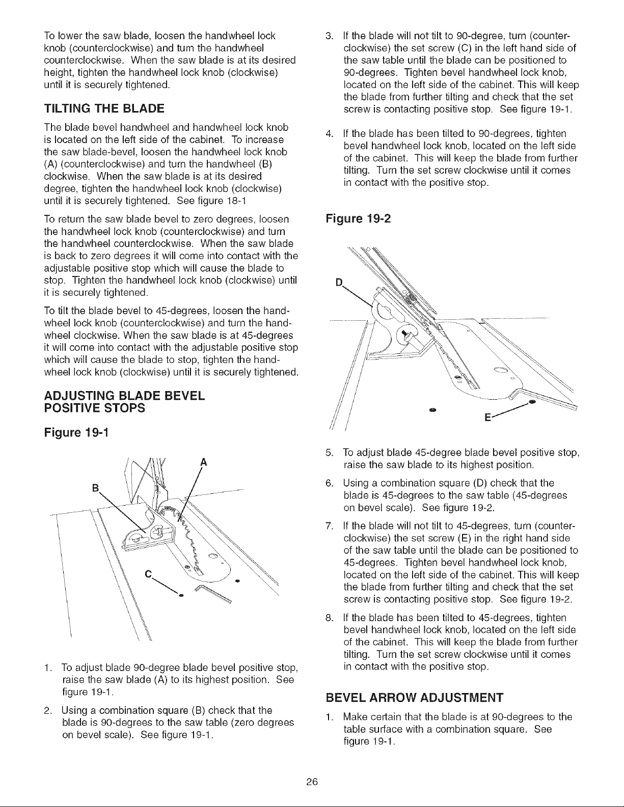
RAISING AND LOWERING THE BLADE
Figure 18=1
1.
The ON/OFF switch is located under the front rail
on the table saw.
2.
To turn the table saw on, press the green "ON"
button (A) in one-half inch. Note: There is a safety
feature on the switch to insure that the switch must
be completely pressed before the saw will START.
See figure 17-1.
3.
To turn the table saw off, press the large red "OFF"
paddle (B) or lift the paddle and press directly on
the red "OFF" button. See figure 17-1.
The blade height adjustment handwheel and handwheel
lock knob is located on the front of the cabinet above
the blade bevel scale. To raise the saw blade, loosen
the handwheel lock knob (A) (counter-clockwise) and
turn the handwheel (B) clockwise. When the saw blade
is at its desired height, tighten the handwheel lock knob
(clockwise) until it is securely tightened. See figure 18-1.
25
Tolowerthesawblade,loosenthehandwheellock
knob(counterclockwise)andturnthehandwheel
counterclockwise.Whenthesawbladeisatitsdesired
height,tightenthehandwheellockknob(clockwise)
untilitissecurelytightened.
TILTING THE BLADE
The blade bevel handwheel and handwheel lock knob
is located on the left side of the cabinet. To increase
the saw blade-bevel, loosen the handwheel lock knob
(A) (counterclockwise) and turn the handwheel (B)
clockwise. When the saw blade is at its desired
degree, tighten the handwheel lock knob (clockwise)
until it is securely tightened. See figure 18-1
3.
If the blade will not tilt to 90-degree, turn (counter-
clockwise) the set screw (C) in the left hand side of
the saw table until the blade can be positioned to
90-degrees. Tighten bevel handwheel lock knob,
located on the left side of the cabinet. This will keep
the blade from further tilting and check that the set
screw is contacting positive stop. See figure 19-1.
4.
If the blade has been tilted to 90-degrees, tighten
bevel handwheel lock knob, located on the left side
of the cabinet. This will keep the blade from further
tilting. Turn the set screw clockwise until it comes
in contact with the positive stop.
To return the saw blade bevel to zero degrees, loosen
the handwheel lock knob (counterclockwise) and turn
the handwheel counterclockwise. When the saw blade
is back to zero degrees it will come into contact with the
adjustable positive stop which will cause the blade to
stop. Tighten the handwheel lock knob (clockwise) until
it is securely tightened.
To tilt the blade bevel to 45-degrees, loosen the hand-
wheel lock knob (counterclockwise) and turn the hand-
wheel clockwise. When the saw blade is at 45-degrees
it will come into contact with the adjustable positive stop
which will cause the blade to stop, tighten the hand-
wheel lock knob (clockwise) until it is securely tightened.
ADJUSTING BLADE BEVEL
POSITIVE STOPS
Figure 19=1
A
Figure 19=2
5. To adjust blade 45-degree blade bevel positive stop,
raise the saw blade to its highest position.
6. Using a combination square (D) check that the
blade is 45-degrees to the saw table (45-degrees
on bevel scale). See figure 19-2.
7. If the blade will not tilt to 45-degrees, turn (counter-
clockwise) the set screw (E) in the right hand side
of the saw table until the blade can be positioned to
45-degrees. Tighten bevel handwheel lock knob,
located on the left side of the cabinet. This will keep
the blade from further tilting and check that the set
screw is contacting positive stop. See figure 19-2.
1. To adjust blade 90-degree blade bevel positive stop,
raise the saw blade (A) to its highest position. See
figure 19-1.
2. Using a combination square (B) check that the
blade is 90-degrees to the saw table (zero degrees
on bevel scale). See figure 19-1.
8. If the blade has been tilted to 45-degrees, tighten
bevel handwheel lock knob, located on the left side
of the cabinet. This will keep the blade from further
tilting. Turn the set screw clockwise until it comes
in contact with the positive stop.
BEVEL ARROW ADJUSTMENT
1. Make certain that the blade is at 90-degrees to the
table surface with a combination square. See
figure 19-1.
26
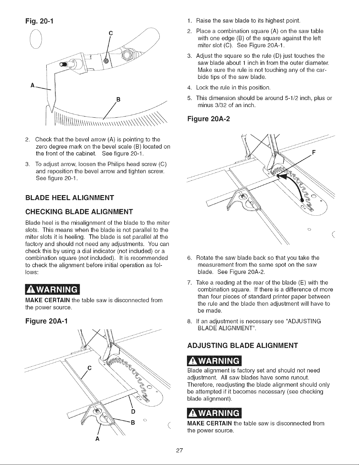
Fig. 20=1
C
\/
2. Check that the bevel arrow (A) is pointing to the
zero degree mark on the bevel scale (B) located on
the front of the cabinet. See figure 20-1.
3. To adjust arrow, loosen the Philips head screw (C)
and reposition the bevel arrow and tighten screw.
See figure 20-1.
1. Raise the saw blade to its highest point.
2. Place a combination square (A) on the saw table
with one edge (B) of the square against the left
miter slot (C). See Figure 20A-1.
3. Adjust the square so the rule (D) just touches the
saw blade about 1 inch in from the outer diameter.
Make sure the rule is not touching any of the car-
bide tips of the saw blade.
4. Lock the rule in this position.
5. This dimension should be around 5-1/2 inch, plus or
minus 3/32 of an inch.
Figure 20A=2
BLADE HEEL ALIGNMENT
CHECKING BLADE ALIGNMENT
Blade heel is the misalignment of the blade to the miter
slots. This means when the blade is not parallel to the
miter slots it is heeling. The blade is set parallel at the
factory and should not need any adjustments. You can
check this by using a dial indicator (not included) or a
combination square (not included). It is recommended
to check the alignment before initial operation as fol-
lows:
MAKE CERTAIN the table saw is disconnected from
the power source.
Figure 20A=1
f
6. Rotate the saw blade back so that you take the
measurement from the same spot on the saw
blade. See Figure 20A-2.
7. Take a reading at the rear of the blade (E) with the
combination square. If there is a difference of more
than four pieces of standard printer paper between
the rule and the blade then adjustment will have to
be made.
8,
If an adjustment is necessary see "ADJUSTING
BLADE ALIGNMENT".
ADJUSTING BLADE ALIGNMENT
Blade alignment is factory set and should not need
adjustment. All saw blades have some runout.
Therefore, readjusting the blade alignment should only
be attempted if it becomes necessary (see checking
blade alignment).
D
MAKE CERTAIN the table saw is disconnected from
the power source.
A
27
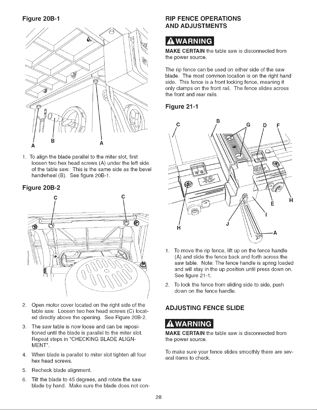
Figure 20B=1
RIP FENCE OPERATIONS
AND ADJUSTMENTS
\
MAKE CERTAIN the table saw is disconnected from
the power source.
The rip fence can be used on either side of the saw
blade. The most common location is on the right hand
side. This fence is a front locking fence, meaning it
only clamps on the front rail. The fence slides across
the front and rear rails.
Figure 21=1
A
1. To align the blade parallel to the miter slot, first
loosen two hex head screws (A) under the left side
of the table saw. This is the same side as the bevel
handwheel (B). See figure 20B-1.
Figure 20B=2
c
C
C G D F
B
E
I
1. To move the rip fence, lift up on the fence handle
(A) and slide the fence back and forth across the
saw table. Note: The fence handle is spring loaded
and will stay in the up position until press down on.
See figure 21-1.
2. To lock the fence from sliding side to side, push
down on the fence handle.
H
2. Open motor cover located on the right side of the
table saw. Loosen two hex head screws (C) locat-
ed directly above the opening. See Figure 20B-2.
3. The saw table is now loose and can be reposi-
tioned until the blade is parallel to the miter slot.
Repeat steps in "CHECKING BLADE ALIGN-
MENT".
4.
When blade is parallel to miter slot tighten all four
hex head screws.
5.
Recheck blade alignment.
6.
Tilt the blade to 45 degrees, and rotate the saw
blade by hand. Make sure the blade does not con-
ADJUSTING FENCE SLIDE
MAKE CERTAIN the table saw is disconnected from
the power source.
To make sure your fence slides smoothly there are sev-
eral items to check.
28
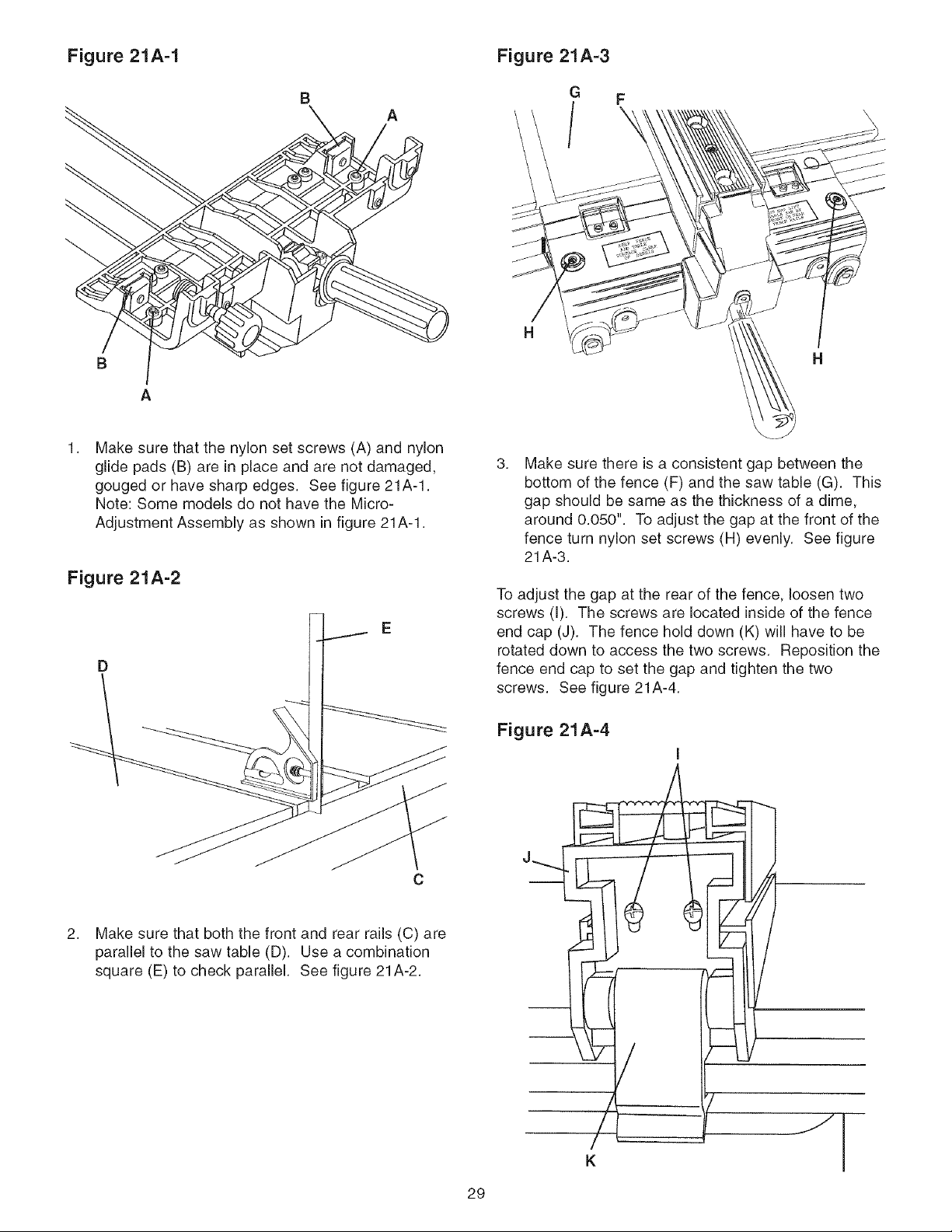
Figure 21A-1
Figure 21A=3
B
B
A
Make sure that the nylon set screws (A) and nylon
glide pads (B) are in place and are not damaged,
gouged or have sharp edges. See figure 21A-1.
Note: Some models do not have the Micro-
Adjustment Assembly as shown in figure 21A-1.
Figure 21A=2
G F
/,
H
3,
Make sure there is a consistent gap between the
bottom of the fence (F) and the saw table (G). This
gap should be same as the thickness of a dime,
around 0.050". To adjust the gap at the front of the
fence turn nylon set screws (H) evenly. See figure
21A-3.
To adjust the gap at the rear of the fence, loosen two
screws (I). The screws are located inside of the fence
end cap (J). The fence hold down (K) will have to be
rotated down to access the two screws. Reposition the
fence end cap to set the gap and tighten the two
screws. See figure 21A-4.
C
2. Make sure that both the front and rear rails (C) are
parallel to the saw table (D). Use a combination
square (E) to check parallel. See figure 21A-2.
Figure 21A=4
I
K
29
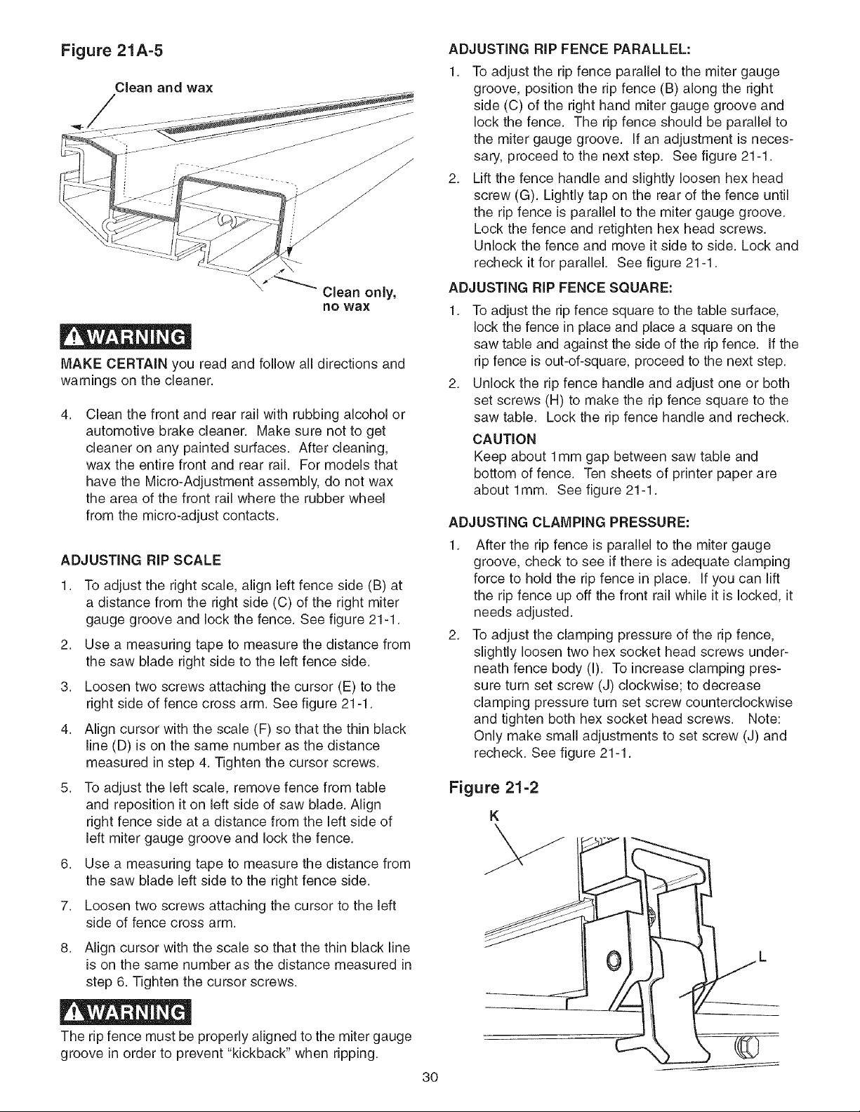
Figure 21A-5
Clean and wax
MAKE CERTAIN you read and follow all directions and
warnings on the cleaner.
4.
Clean the front and rear rail with rubbing alcohol or
automotive brake cleaner. Make sure not to get
cleaner on any painted surfaces. After cleaning,
wax the entire front and rear rail. For models that
have the Micro-Adjustment assembly, do not wax
the area of the front rail where the rubber wheel
from the micro-adjust contacts.
ADJUSTING RiP FENCE PARALLEL:
1. To adjust the rip fence parallel to the miter gauge
groove, position the rip fence (B) along the right
side (C) of the right hand miter gauge groove and
lock the fence. The rip fence should be parallel to
the miter gauge groove. If an adjustment is neces-
sary, proceed to the next step. See figure 21-1.
2. Lift the fence handle and slightly loosen hex head
screw (G). Lightly tap on the rear of the fence until
the rip fence is parallel to the miter gauge groove.
Lock the fence and retighten hex head screws.
Unlock the fence and move it side to side. Lock and
recheck it for parallel. See figure 21-1.
ADJUSTING RiP FENCE SQUARE:
1. To adjust the rip fence square to the table surface,
lock the fence in place and place a square on the
saw table and against the side of the rip fence. Ifthe
rip fence is out-of-square, proceed to the next step.
2. Unlock the rip fence handle and adjust one or both
set screws (H) to make the rip fence square to the
saw table. Lock the rip fence handle and recheck.
CAUTION
Keep about 1mm gap between saw table and
bottom of fence. Ten sheets of printer paper are
about lmm. See figure 21-1.
ADJUSTING CLAMPING PRESSURE:
ADJUSTING RiP SCALE
1. To adjust the right scale, align left fence side (B) at
a distance from the right side (C) of the right miter
gauge groove and lock the fence. See figure 21-1.
2. Use a measuring tape to measure the distance from
the saw blade right side to the left fence side.
3. Loosen two screws attaching the cursor (E) to the
right side of fence cross arm. See figure 21-1.
4. Align cursor with the scale (F) so that the thin black
line (D) is on the same number as the distance
measured in step 4. Tighten the cursor screws.
5. To adjust the left scale, remove fence from table
and reposition it on left side of saw blade. Align
right fence side at a distance from the left side of
left miter gauge groove and lock the fence.
6. Use a measuring tape to measure the distance from
the saw blade left side to the right fence side.
7. Loosen two screws attaching the cursor to the left
side of fence cross arm.
8. Align cursor with the scale so that the thin black line
is on the same number as the distance measured in
step 6. Tighten the cursor screws.
1. After the rip fence is parallel to the miter gauge
groove, check to see if there is adequate clamping
force to hold the rip fence in place. If you can lift
the rip fence up off the front rail while it is locked, it
needs adjusted.
2. To adjust the clamping pressure of the rip fence,
slightly loosen two hex socket head screws under-
neath fence body (I). To increase clamping pres-
sure turn set screw (J) clockwise; to decrease
clamping pressure turn set screw counterclockwise
and tighten both hex socket head screws. Note:
Only make small adjustments to set screw (J) and
recheck. See figure 21-1.
Figure 21=2
K
The rip fence must be properly aligned to the miter gauge
groove in order to prevent "kickback" when ripping.
30
 Loading...