

Craftsman 152220180, 152220600 Owner’s Manual

Owner's Manual
8-in. Wheel
314 Horsepower (continuous duty)
3450 R.P.M. (no load speed)
8-in. BENCH
GRINDER
Model No.
152.220180
C us
CAUTION:
FOR YOUR OWN SAFETY; Read and follow
all of the Safety and Operating Instructions
before Operating this Bench Grinder
10-in. Wheel
1 Horsepower (continuous duty)
1725 R.P.M. (no load speed)
10-in. BENCH
GRINDER
Model No.
152.220600
Customer Helpline
1-800-897-7709
Please have your Model No.
and Serial No. available.
Sears, Roebuck and Co., Hoffman Estates, IL 60179 U.S.A.
Part No. OR94750 VER. 12.07
Espafiol pg. 19

SECTION PAGE
Warranty .......................................................................................................................................................................... 2
Product Specifications ................................................................................................................................................... 2
Safety Instructions ......................................................................................................................................................... 3
Grounding Instructions .................................................................................................................................................. 5
Specific Safety Instructions for Bench Grinders ........................................................................................................ 6
Accessories and Attachments ...................................................................................................................................... 6
Carton Contents .............................................................................................................................................................. 7
Know Your Bench Grinder ............................................................................................................................................. 8
Assembly Instructions ................................................................................................................................................... 9
Operating the Bench Grinder ...................................................................................................................................... 11
Maintenance .................................................................................................................................................................. 13
Troubleshooting Guide ................................................................................................................................................ 13
Parts List ....................................................................................................................................................................... 14
Espahol .......................................................................................................................................................................... 19
FULL ONE YEAR WARRANTY
If this product fails due to a defect in material or workmanship within one year from the date of purchase, return it
to the nearest Sears Service Center for repair, free of charge.
This warranty gives you specific legal rights, and you may also have other rights, which vary, from state to state.
Sears, Roebuck and Co., Dept. 817 WA, Hoffman Estates, IL 60179
8-in. Bench Grinder 10-in. Bench Grinder
Motor Motor
Continuous duty HP 3/4 Continuous duty HP
Volts 120 Volts
Hertz 60 Hertz
RPM 3450 R.P.M. (no load speed) RPM
Grinding Wheel Size 8" diameter x 1" face x Grinding Wheel Size
1" bore
Grinding Wheel Grit
Shaft diameter
Arbor Bushing
Lamp
Tool Rests
Eye Shield Assemblies
Spark Arrestors
Quench tray
Wheel Dresser
60, 120
5/8" diameter
1" diameter x 1" face by
5/8" bore
120V, 40 watt Type A or
smaller bulb-Medium Base
(bulb not included)
Left and Right
Clear Lexan Left and Right
Left and Right
Yes
Yes
Grinding Wheel Grit
Shaft diameter
Arbor Bushing
Lamp
Tool Rests
Eye Shield Assemblies
Spark Arrestors
Quench tray
Wheel dresser
1
120
6O
1725 R.P.M. (no load speed)
10" diameter x 1" face x
1-1/4" bore
60, 120
3/4" diameter
1-1/4" diameter x 1" face by
3/4" bore
120V, 40 watt Type A or
smaller bulb-Medium Base
(bulb not included)
Left and Right
Clear Lexan Left and Right
Left and Right
Yes
Yes

Toavoidelectricalshocktoyourselfanddamagetothe
BenchGrinder,usepropercircuitprotection.
TheBenchGrinderisfactorywiredfor120V,60Hz,
operation.Connectto a120V,15ampbranchcircuit
andusea15amptimedelayfuseorcircuitbreaker.
Theelectricalcircuitcannothaveanywiresizeless
than#14.Toavoidshockorfire,replacepowercord
immediatelyifitisdamagedinanyway.
GENERAL SAFETY INSTRUCTIONS
Operating a Bench Grinder can be dangerous if safety
and common sense are ignored. The operator must be
familiar with the operation of the tool. Read this manual
to understand this Bench Grinder. DO NOT operate this
Bench Grinder if you do not fully understand the limita-
tions of this tool. DO NOT modify this Bench Grinder in
any way.
BEFORE USING THE BENCH GRINDER
To avoid serious injury and damage to the tool, read
and follow all of the Safety and Operating Instructions
before operating the Bench Grinder.
,
Some dust created by using power tools contains
chemicals known to the State of California to cause
cancer, birth defects, or other reproductive harm.
Some examples of these chemicals are:
• Lead from lead-based paints.
• Crystalline silica from bricks, cement, and other
masonry products.
• Arsenic and chromium from chemically treated
lumber.
Your risk from these exposures varies, depending
on how often you do this type of work. To reduce
your exposure to these chemicals: work in a well-
ventilated area, and work with approved safety
equipment, such as those dust masks that are spe-
cially designed to filter out microscopic particles.
,
READ the entire Owner's Manual. LEARN how to
use the tool for its intended applications.
,
GROUND ALL TOOLS. If the tool is supplied with a
3-prong plug, it must be plugged into a 3-contact
electrical receptacle. The 3rd prong is used to
ground the tool and provide protection against
accidental electric shock. DO NOT remove the 3rd
prong. See Grounding Instructions on page 5.
,
AVOID A DANGEROUS WORKING ENVIRON-
MENT. DO NOT use electrical tools in a damp
environment or expose them to rain.
,
DO NOT use electrical tools in the presence of
flammable liquids or gasses.
,
ALWAYS keep the work area clean, well lit, and
organized. DO NOT work in an environment with
floor surfaces that are slippery from debris, grease,
and wax.
,
KEEP VISITORS AND CHILDREN AWAY. DO NOT
permit people to be in the immediate work area,
especially when the electrical tool is operating.
,
DO NOT FORCE THE TOOL to perform an opera-
tion for which it was not designed. It will do a safer
and higher quality job by only performing operations
for which the tool was intended.
,
WEAR PROPER CLOTHING. DO NOT wear loose
clothing, gloves, neckties, or jewelry. These items
can get caught in the machine during operations
and pull the operator into the moving parts. The
user must wear a protective cover on their hair, if
the hair is long, to prevent it from contacting any
moving parts.
10.
ALWAYS WEAR EYE PROTECTION. Any power
tool can throw debris into the eyes during opera-
tions, which could cause severe and permanent
eye damage. ALWAYS wear Safety Goggles (that
comply with ANSI standard Z87.1) when operating
power tools. Safety Goggles are available at Sears
Retail Stores.
11.
WEAR A DUST MASK TO PREVENT INHALING
DANGEROUS DUST OR PARTICLES.
12.
ALWAYS UNPLUG THE TOOL FROM THE ELEC-
TRICAL RECEPTACLE when making adjustments,
changing parts or performing any maintenance.
13.
KEEP PROTECTIVE GUARDS IN PLACE AND IN
WORKING ORDER.
14.
AVOID ACCIDENTAL STARTING. Make sure that
the power switch is in the "OFF" position before
plugging in the power cord to the electrical
receptacle.
15.
REMOVE ALL MAINTENANCE TOOLS from the
immediate area prior to turning "ON" the Bench
Grinder.

16.USE ONLY RECOMMENDED ACCESSORIES.
Use of incorrect or improper accessories could
cause serious injury to the operator and cause
damage to the tool. If in doubt, check the instruction
manual that comes with that particular accessory.
17. NEVER LEAVE A RUNNING TOOL UNATTENDED.
Turn the power switch to the "OFF" position. DO
NOT leave the tool until it has come to a complete
stop.
18. DO NOT STAND ON A TOOL. Serious injury could
result if the tool tips over or you accidentally contact
the tool.
19. DO NOT store anything above or near the tool
where anyone might try to stand on the tool to
reach it.
20. MAINTAIN YOUR BALANCE. DO NOT extend
yourself over the tool. Wear oil resistant rubbersoled
shoes. Keep floor clear of debris, grease, and wax.
21. MAINTAIN TOOLS WITH CARE. Always keep tools
clean and in good working order. Keep all blades
and tool bits sharp.
22. EACH AND EVERY TIME, CHECK FOR DAMAGED
PARTS PRIOR TO USING THE TOOL. Carefully
check all guards to see that they operate properly,
are not damaged, and perform their intended func-
tions. Check for alignment, binding or breaking of
moving parts. A guard or other part that is damaged
should be immediately repaired or replaced.
23. CHILDPROOF THE WORKSHOP AREA by remov-
ing switch keys, unplugging tools from the electrical
receptacles, and using padlocks.
27.
Information regarding the safe and proper operation
of this tool is also available from the following
sources:
Power Tool Institute
1300 Summer Avenue
Cleveland, OH 44115-2851
www.powertoolinstit ute.org
National Safety Council
1121 Spring Lake Drive
Itasca, IL 60143-3201
American National Standards Institute
25West 43rd. St, 4th Floor
New York, NY. 10036
ANSI 01.1 Safety Requirements
For Woodworking Machines
WWW.ANSI.ORG
U.S. Department of Labor Regulations
OSHA 1910.213 Regulations
WWW.OSHA.GOV
GUIDELINES FOR
EXTENSION CORDS
If you are using an extension cord outdoors, be sure
it is marked with the suffix "W-A" ("W" in Canada) to
indicate that it is acceptable for outdoor use.
Be sure your extension cord is properly sized, and
in good electrical condition. Always replace a damaged
extension cord or have it repaired by a qualified person
before using it.
24 DO NOT OPERATE TOOL IF UNDER THE INFLU-
ENCE OF DRUGS OR ALCOHOL.
25. SECURE ALL WORK. Use clamps or jigs to secure
the workpiece. This is safer than attempting to hold
the workpiece with your hands.
26. USE A PROPER EXTENSION CORD IN GOOD
CONDITION. When using an extension cord, be
sure to use one heavy enough to carry the current
your product will draw. The table at right shows the
correct size to use depending on cord length and
nameplate amperage rating. If in doubt, use the
next heavier gauge. The smaller the gauge number,
the larger diameter of the extension cord. If in doubt
of the proper size of an extension cord, use a short-
er and thicker cord. An undersized cord will cause a
drop in line voltage resulting in a loss of power and
overheating. USE ONLY A 3-WIRE EXTENSION
CORD THAT HAS A 3-PRONG GROUNDING
PLUG AND A 3-POLE RECEPTACLE THAT
ACCEPTS THE TOOL'S PLUG.
Protect your extension cords from sharp objects,
excessive heat, and damp or wet areas.
120VOLTOPERATIONONLY
0to 6Amps
6 to 10Amps
10to 12Amps
25' LONG
18AWG
18AWG
16AWG
50' LONG 100'LONG
16AWG 16AWG
16AWG 14AWG
16AWG 14AWG
150'LONG
14AWG
12AWG
12AWG
II
IN THE EVENT OF A MALFUNCTION OR BREAK-
DOWN, grounding provides the path of least resistance
for electric current and reduces the risk of electric
shock. This tool is equipped with an electric cord that
has an equipment grounding conductor and a ground-
ing plug. The plug MUST be plugged into a matching
electrical receptacle that is properly installed and ground-
ed in accordance with ALL local codes and ordinances.
DO NOT MODIFY THE PLUG PROVIDED. If it will not
fit the electrical receptacle, have the proper electrical
receptacle installed by a qualified electrician.
IMPROPER ELECTRICAL CONNECTION of the equip-
ment grounding conductor can result in risk of electric
shock. The conductor with the green insulation (with or
without yellow stripes) is the equipment grounding
conductor. DO NOT connect the equipment grounding
conductor to a live terminal.
CHECK with a qualified electrician or service personnel
if you do not completely understand the grounding
instructions, or if you are not sure the tool is properly
grounded.
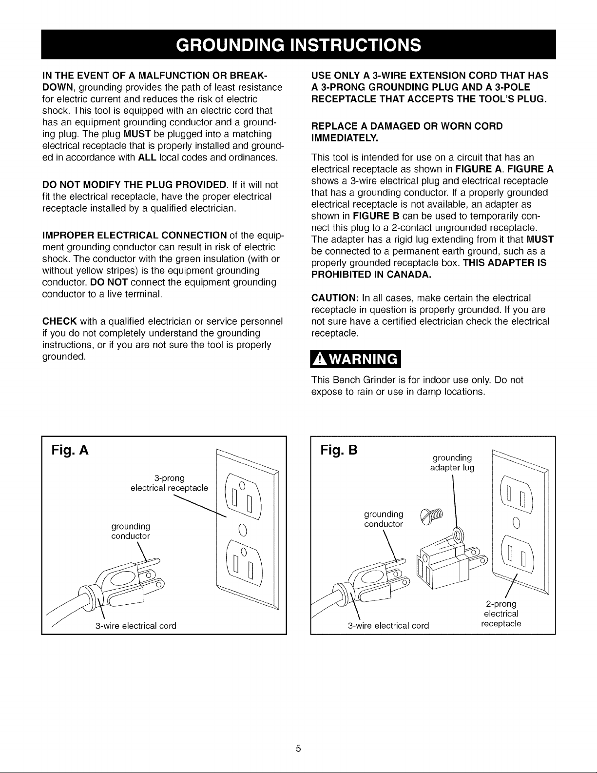
USE ONLY A 3-WIRE EXTENSION CORD THAT HAS
A 3-PRONG GROUNDING PLUG AND A 3-POLE
RECEPTACLE THAT ACCEPTS THE TOOL'S PLUG.
REPLACE A DAMAGED OR WORN CORD
IMMEDIATELY.
This tool is intended for use on a circuit that has an
electrical receptacle as shown in FIGURE A. FIGURE A
shows a 3-wire electrical plug and electrical receptacle
that has a grounding conductor. If a properly grounded
electrical receptacle is not available, an adapter as
shown in FIGURE B can be used to temporarily con-
nect this plug to a 2-contact ungrounded receptacle.
The adapter has a rigid lug extending from it that MUST
be connected to a permanent earth ground, such as a
properly grounded receptacle box. THIS ADAPTER IS
PROHIBITED IN CANADA.
CAUTION: In all cases, make certain the electrical
receptacle in question is properly grounded. If you are
not sure have a certified electrician check the electrical
receptacle.
Fig. A
3-prong
electrical receptacle
grounding
conductor
3-wire electrical cord
0
This Bench Grinder is for indoor use only. Do not
expose to rain or use in damp locations.
Fig. B
grounding
conductor
3-wire electrical cord
grounding
adapter lug
0
2-prong
electrical
receptacle

SPECIFIC SAFETY INSTRUCTIONS
FOR BENCH GRINDERS
The operation of any grinder can result in debris being
thrown into your eyes, which can result in severe eye
damage. ALWAYS wear Safety Goggles (that comply
with ANSI standard Z87.1 ) when operating the grinder.
Safety Goggles are available at Sears Retail Stores.
Keep your thumbs and fingers away from the grinding
wheels.
.
ALWAYS USE THE EYE SHIELDS AND WHEEL
GUARDS provided with the grinder.
.
REPLACE A CRACKED OR DAMAGED GRIND-
ING WHEEL IMMEDIATELY. A damaged wheel can
discharge debris at a high velocity towards the
operator. Carefully handle the grinding wheels since
they are abrasive. Prior to replacing a grinding
wheel, check it for cracks. DO NOT remove the
blotter or label on both sides of the grinding wheel.
Tighten the spindle nut just enough to hold the
grinding wheel firmly to the Bench Grinder. Do not
over-tighten the nut. Excessive clamping force can
damage the grinding wheel. Only use the wheel
flanges provided with the grinder. When selecting a
replacement grinding wheel, verify that the grinding
wheel has a higher R.P.M. rating than the maximum
R.P.M. of the Bench Grinder.
THE BENCH GRINDER WILL PRODUCE SPARKS
.
AND DEBRIS DURING GRINDING OPERATIONS.
Be sure that there are not any flammable materials
in the vicinity. Frequently clean grinding dust from
the back of the Bench Grinder.
NEVER FORCE THE WORKPIECE AGAINST A
.
GRINDING WHEEL, especially if the wheel is cold.
Apply the workpiece slowly, allowing the grinding
wheel an opportunity to warm up. This will minimize
the chance of wheel breakage. DO NOT grind using
the sides of the grinding wheels. DO NOT apply
coolant directly to the grinding wheel.
.
KEEP ALL WHEEL GUARDS IN PLACE. DO NOT
USE THE BENCH GRINDER WITH THE WHEEL
GUARDS REMOVED.
KEEP THE TOOL RESTS FIRMLY TIGHTENED.
.
9.
ALWAYS USE THE SUPPLIED WHEEL DRESSER
TO RESURFACE THE FACE OF THE GRINDING
WHEEL.
10.
REMOVE ADJUSTING KEYS AND WRENCHES.
Form habit of checking to see that keys and adjust-
ing wrenches are removed from tool before turning
it on.
11. USE RIGHT TOOL. Don't force tool or attachment
to do a job for which it was not designed.
12. DO NOT overtighten wheel nut.
.
THE DIAMETER OF THE GRINDING WHEELS
WILL DECREASE WITH USE. Adjust the tool rests
and spark arrestors to maintain a distance of 1/16"
from the wheel.
.
DO NOT STAND IN FRONT OF THE BENCH
GRINDER WHEN STARTING IT. Stand to one side
of the Bench Grinder and turn it "ON". Wait at the
side for one minute until the grinder comes up to
full speed. There is always a possibility that debris
from a damaged grinding wheel may be discharged
towards the operator.
AVAILABLE ACCESSORIES
Visit your Sears Hardware Department or see the
Sears Power and Hand Tool Catalog for the following
accessories.
ITEM
Replacement grinding wheels
Wire and Buffing wheels
Spacers
Wheel dressers
Stand
STOCK NUMBER
See catalog or store
See catalog or store
See catalog or store
See catalog or store
See catalog or store
13. ONLY use flanges furnished with the grinder.
14. FREQUENTLY clean grinding dust from beneath
grinder.
15. DO NOT FORCE THE TOOL to perform an opera-
tion for which it was not designed. It will do a safer
and higher quality job by only performing operations
for which the tool was intended.
Sears may recommend other accessories not listed in
this manual.
See your nearest Sears Hardware Department or Sears
Power and Hand Tool Catalog for other accessories.
Do not use any accessory unless you have completely
read the Owner's Manual for that accessory.
Use only accessories recommended for this Bench
Grinder. Using other accessories may cause serious
injury and cause damage to the Bench Grinder.

UNPACKING AND CHECKING
CONTENTS (Fig. C)
Bench Grinder can only be turned "ON" after all the
parts have been obtained and installed correctly.
This Bench Grinder will require a minimal amount of
assembly. A 10mm and 13mm open end wrench is
provided for mounting the Tool Rest Assemblies and
the Spark Arrestor Assemblies.
Remove all of the parts from the shipping box and lay
them on a clean work surface. Compare the items to
Fig. C, verify that all items are accounted for before
discarding the shipping box.
If any parts are missing, do not attempt to plug in the
power cord and turn "ON" the Bench Grinder. The
Fig. C
The following items are to be provided in the shipping
box:
A. Grinder
B. Quench tray
C. Wheel dresser
D. Eyeshield assembly
E. Left tool rest assembly (not shown)
F. Right tool rest assembly
G. Special Wrench
A
F
D
/
C

6
10B
9
4
7
3
-10A
2
8
11
©
13
.
WHEEL GUARD - Covers the grinding wheels and
protects against accidental contact.
.
WHEEL COVER - Covers the grinding wheels and
provides access for routine maintenance.
3. MOTOR HOUSING - Contains the electrical motor.
4. EYESHIELD MOUNTS - Supports the eyeshields.
5. EYESHIELDS - Protective Lexan see-thru shields
to prevent any loose debris from contacting the
operator.
6. FLEXIBLE WORK LIGHT - Provides assistance to
the operator for grinding operations.
7. SPARK ARRESTORS - Prevents hot sparks and
debris from contacting the operator.
8. TOOL REST ADJUSTABLE SUPPORTS - Lets the
operator position the tool rest closer to the wheel as
the wheel decreases in diameter due to wear.
9. TOOL RESTS - Used to support the workpiece
that is being ground. Adjustable to provide angled
surfaces.
10. A) GRINDING WHEEL 120 GRIT - Used to remove
light material from workpiece.
10. B) GRINDING WHEEL 60 GRIT - Used to remove
heavy material from workpiece.
11. ON / OFF SWITCH - Used to turn "ON" and turn
"OFF" the grinder.
12. WHEEL DRESSER - Used to clean and smooth
surface of the Grinding Wheel (not shown).
13. QUENCH TRAY - Used to cool workpiece after
grinding.
14. MOUNTING PAD - Used to secure the grinder to a
workbench or suitable work surface.
15. GRINDING WHEEL IDENTIFICATION LABEL -
Provides information on wheel size, grit and maxi-
mum RPM. Must be left on to distribute the load of
tightening the Lock Nuts (not shown).
16. ARBOR BUSHING - Used when wheels have an
oversized wheel bore (not shown).
17. FLANGES - Used to secure the grinding wheels to
the grinder and distribute the load of the Lock Nuts
(not shown).
18. LOCK NUT - Used to secure the grinding wheels to
the grinder (not shown).
A10mmand13mmopen-endwrench(included)is
requiredforassemblyoftheToolRestAssembliesand
theSparkArrestorAssemblies.
• DONOTassembletheBenchGrinderuntilyouare
surethetoolISNOTpluggedin.
• DONOTassembletheBenchGrinderuntilyouare
surethepowerswitchisinthe"OFF"position.
• DONOTassembletheBenchGrinderuntilyouare
surethegrindingwheelsarefirmlytightenedtothe
BenchGrinder.
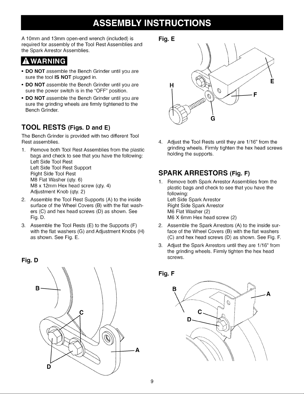
TOOL RESTS (Figs. D and E)
The Bench Grinder is provided with two different Tool
Rest assemblies.
1. Remove both Tool Rest Assemblies from the plastic
bags and check to see that you have the following:
Left Side Tool Rest
Left Side Tool Rest Support
Right Side Tool Rest
M8 Flat Washer (qty. 6)
M8 x 12mm Hex head screw (qty. 4)
Adjustment Knob (qty. 2)
2. Assemble the Tool Rest Supports (A) to the inside
surface of the Wheel Covers (B) with the flat wash-
ers (C) and hex head screws (D) as shown. See
Fig. D.
3. Assemble the Tool Rests (E) to the Supports (F)
with the flat washers (G) and Adjustment Knobs (H)
as shown. See Fig. E.
Fig. D
Fig. E
E
H
F
G
4. Adjust the Tool Rests until they are 1/16" from the
grinding wheels. Firmly tighten the hex head screws
holding the supports.
SPARK ARRESTORS (Fig. F)
1. Remove both Spark Arrestor Assemblies from the
plastic bags and check to see that you have the
following:
Left Side Spark Arrestor
Right Side Spark Arrestor
M6 Flat Washer (2)
M6 X 6mm Hex head screw (2)
2. Assemble the Spark Arrestors (A) to the inside sur-
face of the Wheel Covers (B) with the flat washers
(C) and hex head screws (D) as shown. See Fig. F.
3. Adjust the Spark Arrestors until they are 1/16" from
the grinding wheels. Firmly tighten the hex head
screws.
Fig. F
B
C
D

EYE SHIELDS (Fig. G)
WORK LIGHT (Fig. H)
,
Remove both Eye Shield Assemblies from the plas-
tic bags and check to see that you have the follow-
ing. Eyeshield (qty. 2) Lock Knob (qty. 2) Spacer
(qty. 2) M6 Flat washer (qty. 2) M6 x 80mm carriage
head screw (qty. 2)
,
Assemble the Eyeshield (C) to the Spark Arrestor
(A) by inserting the carriage head screw (B) through
Eyeshield (C), Spark Arrestor (A), and the spacer
(D) as shown.
3. Assemble the flat washer (E) and Lock Knob (F) to
the carriage head screw and tighten until the
Eyeshield remains in the desired position.
Fiq. G
D
B
E
The Bench Grinder is provided with a Flexible Work
Light to assist in visibility of the workpiece.
The Bench Grinder is NOT provided with a light bulb for
the Flexible Work Light.
To reduce the risk of fire, use a 120V. 40 watt Type A or
smaller bulb, medium base. DO NOT use a light bulb
that extends past the end of the light housing.
The Flexible Work Light (A) may be turned "ON" or
"OFF" by using the rotary switch (B) on the top surface
of the housing. The switch can be rotated in the clock-
wise direction only.
NOTE: The Flexible Work Light can be turned "ON" or
"OFF" even if the Bench Grinder is turned "OFF".
CAUTION: The Flexible Work Light housing will remain
hot for a few minutes after turning it "OFF". Avoid con-
tact with housing until it is cool.
Fig. H
B
QUENCH TRAY
1. The Quench Tray is provided to cool the workpiece
during and after grinding operations.
2. Attach the Quench Tray to base of the Bench
Grinder as shown.
3. Tighten the two screws.
4. Partially fill the Quench Tray with water. DO NOT
overfill? DO NOT use any other liquid in the Quench
Tray other than water.
A
PERMANENT MOUNTING
You should firmly attach the Bench Grinder to a solid work
surface or heavy-duty stand (hardware not included).
5. Place the workpiece into the water after performing
the grinding operation to cool it.
6. DO NOT put any water directly onto the grinding
wheels.
If the Bench Grinder is not securely mounted, it will
have the ability to move or tip over during grinding
operations and possibly cause the operator's fingers to
contact the grinding wheels.
10
 Loading...