

Craftsman 152219070 Owner’s Manual

truction anu
C
®
C S
FOR YOUR OWN SAFETY; Read
and foUlow all of the Safety and
Operating Instructions before
Operating this Mortiser.
Customer Helpline
1-800-897-7709
PRease have your Model No.
and SedaR No. availabUe.
Sears, Roebuck and Co., Hoffman Estates, JL 60179 U.S.A.
Part No. OR93760
Revision A
EspaSoU,pg. 29

SECTION PAGE
Warranty .......................................................................................................................................................................... 2
Product Specifications ................................................................................................................................................... 2
Safety Instructions ......................................................................................................................................................... 3
Guidelines for extension cords ..................................................................................................................................... 4
Grounding Instructions .................................................................................................................................................. 5
Specific Safety Instructions .......................................................................................................................................... 6
Accessories and Attachments ...................................................................................................................................... 7
Carton Contents ............................................................................................................................................................. 8
Know Your Mortiser ........................................................................................................................................................ 9
Assembly Instructions ................................................................................................................................................. 10
Operations and Adjustment ........................................................................................................................................ 16
Maintenance .................................................................................................................................................................. 24
Troubleshooting Guide ................................................................................................................................................ 25
Part List ......................................................................................................................................................................... 26
Espaffo[ .......................................................................................................................................................................... 29
Service Information ........................................................................................................................................ Back Page
ONE-YEAR FULL WARRANTY ON CRAFTSMAN TOOL
if this Craftsman tool fails due to a defect in material or workmanship within one year from the date of purchase,
CALL 1-800-4-MY-HOME <R>TO ARRANGE FOR FREE REPAIR,
if this tool is used for commercial or rental purposes, this warranty wiii apply for only ninety days from the date of
purchase,
This warranty applies only while this tool is in the United States,
This warranty gives you specific legal rights, and you may also have other rights, which vary from state to state,
Sears, Roebuck and Co,, Dept 817WA, Heffman Estates, IL 60179
Motor type: induction Riser block included Yes
Continuous duty HP 1/2 hp Riser block height 2-1/4"
Maximum Developed HP 7/8 hp Fence compatible with riser Yes
Amps 6 Micro-adjust compatible with riser Yes
Volts 120 Maximum stroke: 5"
Hertz 60 Under head to base: 8"
RPM 1725 Chisel center to fence: 3-1/8"
Chuck type Keyed Under hold down, down position: 7/8" to 3-1/4"
Chuck Maximum capacity 3/8" Under hold down, up position: 1-7/8" to 4-1/4"
Chisel sizes: 1/4" x 1/4" Fence size: 14-1/2" x 2-1/2"
5/16" x 5/16" Base size: 13-3/4" x 8-3/4"
3/8" x 3/8" Overall dimensions: Height: 31"
1/2" x 1/2" Width: 14-1/2"
Yes Depth: 16-1/2"
Bit Holder Yes Weight: 68 Ibs,
Handle position Left or right,
GENERAL SAFETY iNSTRUCTiONS
Operating a Mortiser can be dangerous if safety and
common sense are ignored, The operator must be
familiar with the operation of the tool, Read this manual
to understand this Mortiser, DO NOT operate this
Mortiser if you do not fully understand the limitations
of this tool, DO NOT modify this Mortiser in any way,
REMEMBER: Your personal safety is your
responsibility,
BEFORE USUNG THE MORTISER
To avoid serious injury and damage to the tool, read
and follow all of the Safety and Operating instructions
before operating the Mortiser,
9,
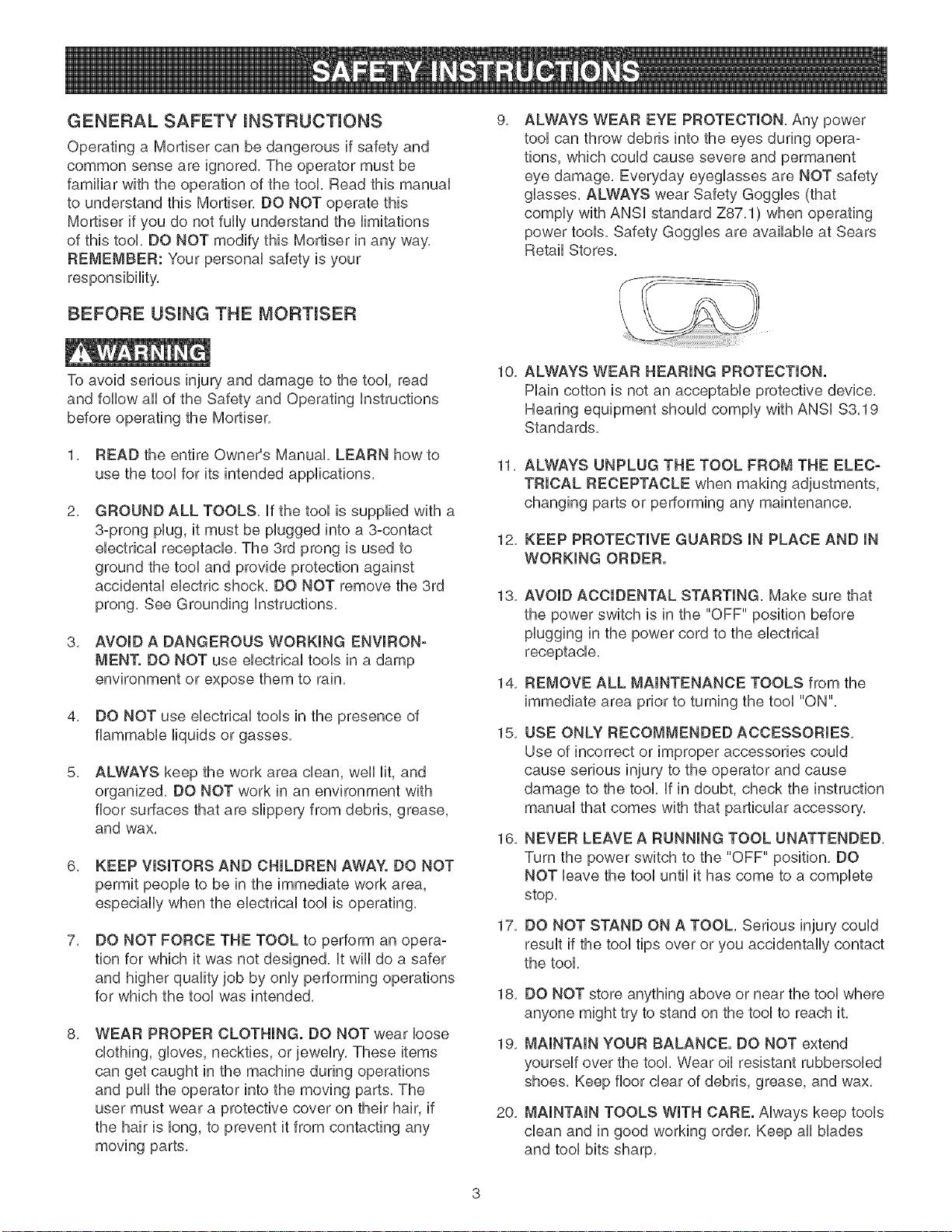
ALWAYS WEAR EYE PROTECTmON, Any power
tool can throw debris into the eyes during opera-
tions, which could cause severe and permanent
eye damage, Everyday eyeglasses are NOT safety
glasses, ALWAYS wear Safety Goggles (that
comply with ANSi standard Z87,1) when operating
power tools, Safety Goggles are available at Sears
Retail Stores,
S
I
\
10,
ALWAYS WEAR HEARING PROTECTION.
Plain cotton is not an acceptable protective device,
Hearing equipment should comply with ANSi $3,19
Standards,
1, READ the entire Owner's Manual, LEARN how to
use the tool for its intended applications,
2,
GROUND ALL TOOLS, if the tool is supplied with a
3-prong plug, it must be plugged into a 3-contact
electrical receptacle, The 3rd prong is used to
ground the tool and provide protection against
accidental electric shock, DO NOT remove the 3rd
prong, See Grounding instructions,
3, AVOID A DANGEROUS WORKmNG ENVIRON-
MEN'[. DO NOT use electrical tools in a damp
environment or expose them to rain,
4, DO NOT use electrical tools in the presence of
flammable liquids or gasse&
5,
ALWAYS keep the work area clean, well lit, and
organized, DO NOT work in an environment with
floor surfaces that are slippery from debris, grease,
and wax,
6, KEEP VISITORS AND CHILDREN AWAY. DO NOT
permit people to be in the immediate work area,
especially when the electrical tool is operating,
7,
DO NOT FORCE THE TOOL to perform an opera-
tion for which it was not designed, it wiii do a safer
and higher quality job by only performing operations
for which the tool was intended,
8, WEAR PROPER CLOTHING. DO NOT wear loose
clothing, gloves, neckties, or jewelry, These items
can get caught in the machine during operations
and pull the operator into the moving parts, The
user must wear a protective cover on their hair, if
the hair is long, to prevent it from contacting any
moving parts,
11,
ALWAYS UNPLUG THE TOOL FROM THE ELEC-
TRICAL RECEPTACLE when making adjustments,
changing parts or performing any maintenance,
12,
KEEP PROTECTIVE GUARDS IN PLACE AND IN
WORKING ORDER.
13,
AVOID ACCIDENTAL STARTING, Make sure that
the power switch is in the "OFF" position before
plugging in the power cord to the electrical
receptacle,
14,
REMOVE ALL MAINTENANCE TOOLS from the
immediate area prior to turning the tool "ON",
15,
USE ONLY RECOMMENDED ACCESSORIES,
Use of incorrect or improper accessories could
cause serious injury to the operator and cause
damage to the tool, if in doubt, check the instruction
manual that comes with that particular accessory,
16,
NEVER LEAVE A RUNNING TOOL UNATTENDED,
Turn the power switch to the "OFF" position, DO
NOT leave the tool until it has come to a complete
stop,
17,
DO NOT STAND ON A TOOL, Serious injury could
result if the tool tips over or you accidentally contact
the tool,
18,
DO NOT store anything above or near the tool where
anyone might try to stand on the tool to reach it,
19,
MAINTAIN YOUR BALANCE. DO NOT extend
yourself over the tool, Wear oil resistant rubbersoled
shoes, Keep floor clear of debris, grease, and wax,
20,
MAINTAIN TOOLS WITH CARE. Always keep tools
clean and in good working order, Keep all blades
and tool bits sharp,

21,EACHAND EVERY TIME, CHECK FOR DAM-
AGED PARTS PRIOR TO USING THE TOOL,
Carefully check aHguards to see that they operate
properly, are not damaged, and perform their
intended functions, Check for afignment, binding or
breaking of moving parts, A guard or other part that
is damaged shouUd be immediateUy repaired or
repUaced,
22, CHILDPROOF THE WORKSHOP AREA by remov-
ing switch keys, unplugging tools from the electrical
receptacles, and using padlocks,
23, DO NOT OPERATE TOOL IF UNDER THE INFLU-
ENCE OF DRUGS OR ALCOHOL,
24, SECURE ALL WORK, When it is possible, use
clamps or jigs to secure the workpiece, This is safer
than attempting to hold the workpiece with your
hands,
25, STAY ALERT, WATCH WHAT YOU ARE DOING,
AND USE COMMON SENSE WHEN OPERATING
A POWER TOOL. DO NOT USE A TOOL WHILE
TIRED OR UNDER THE INFLUENCE OF DRUGS,
ALCOHOL, OR MEDICATION, A moment of
inattention while operating power tools may result
in serious personal injury,
26, ALWAYS WEAR A DUST MASK TO PREVENT
INHALING DANGEROUS DUST OR AIRBORNE
PARTICLES, including wood dust, crystalline silica
dust and asbestos dust, Direct particles away
from face and body, AUwaysoperate tool in well
ventilated area and provide for proper dust removal,
Use dust collection system whenever possible,
Exposure to the dust may cause serious and
permanent respiratory or other injury, including
silicosis (a serious lung disease), cancer, and
death, Avoid breathing the dust, and avoid pro-
longed contact with dust, Allowing dust to get into
your mouth or eyes, or lay on your skin may pro-
mote absorption of harmful material, Always use
properly fitting NIOSH/OSHA approved respiratory
protection appropriate for the dust exposure, and
wash exposed areas with soap and water,
GUIDELINES FOR EXTENSION CORDS
The smaller the gauge number, the larger diameter of
the extension cord is, if in doubt of the proper size of an
extension cord, use a shorter and thicker cord, An
undersized cord wHUcause a drop in HnevoUtage resuUt-
ing in a bss of power and overheating, USE ONLY A
3-WIRE EXTENSION CORD THAT HAS A 3-PRONG
GROUNDING PLUG AND A 3-POLE RECEPTACLE
THAT ACCEPTS THE TOOL'S PLUG,
If you are using an extension cord outdoors, be sure
it is marked with the suffix "W-A" ("W" in Canada) to
indicate that it is acceptable for outdoor use,
Be sure your extension cord is property sized, and
in good electrical condition, Always replace a damaged
extension cord or have it repaired by a qualified person
before using it,
Protect your extension cords from sharp objects,
excessive heat, and damp or wet areas,
120 VOLT OPERATION ONLY
25'LONG 50' LONG 100' LONG
0 to 6 Amps
6 to 10 Amps
10 to 12 Amps
12 to 15 Amps
18 AWG
18 AWG
16 AWG
14 AWG
16 AWG
16 AWG
16 AWG
12 AWG
16 AWG
14 AWG
14 AWG
Not
recommended
27, USE A PROPER EXTENSION CORD IN GOOD
CONDITION, When using an extension cord, be
sure to use one heavy enough to carry the current
your product will draw, Please see minimum recom-
mended gauge for extension cords (AWG) table for
correct sizing of an extension cord, if in doubt, use
the next heavier gauge,
THINSTOOL MUST BE GROUNDED WHmLEmNUSE
TO PROTECT THE OPERATOR FROM ELECTRmC
SHOCK.
mNTHE EVENT OF A MALFUNCTmON OR BREAK-
DOWN, grounding provides the path of bast resistance
for eUectriccurrent and reduces the risk of eUectric
shock. This tooUis equipped with an eUectric cord that
has an equipment-grounding conductor and a ground-
ing pUug.The pUugMUST be pUugged into a matching
eUectricaUreceptacle that is properUy installed and
grounded in accordance with ALL bcaU codes and
ordinances.
DO NOT MODIFY THE PLUG PROVIDED, if it wHUnot
fit the eUectrbaUreceptacb, have the proper eUectrbaU
receptacle installed by a qualified electrician.
IMPROPER ELECTRICAL CONNECTION of the equip°
ment-grounding conductor can result in risk of electric
shock. The conductor with the green insulation (with or
without yellow stripes) is the equipment-grounding
conductor. DO NOT connect the equipment-grounding
conductor to a live terminal if repair or replacement of
the electric cord or plug is necessary.
CHECK with a qualified electrician or service personnel
if you do not completely understand the grounding
instructions, or if you are not sure the tool is properly
grounded.
The motor supplied with your Mortiser is a 120°volt,
singb-phase motor. It is shipped wired for 120°volt
application. Never connect the green wire to a live
terminal.
USE ONLY A 3-WIRE EXTENSION CORD THAT HAS
A 3=PRONG GROUNDING PLUG AND A 3-POLE
RECEPTACLE THAT ACCEPTS THE TOOL'S PLUG.
REPLACE A DAMAGED OR WORN CORD
IMMEDIATELY.
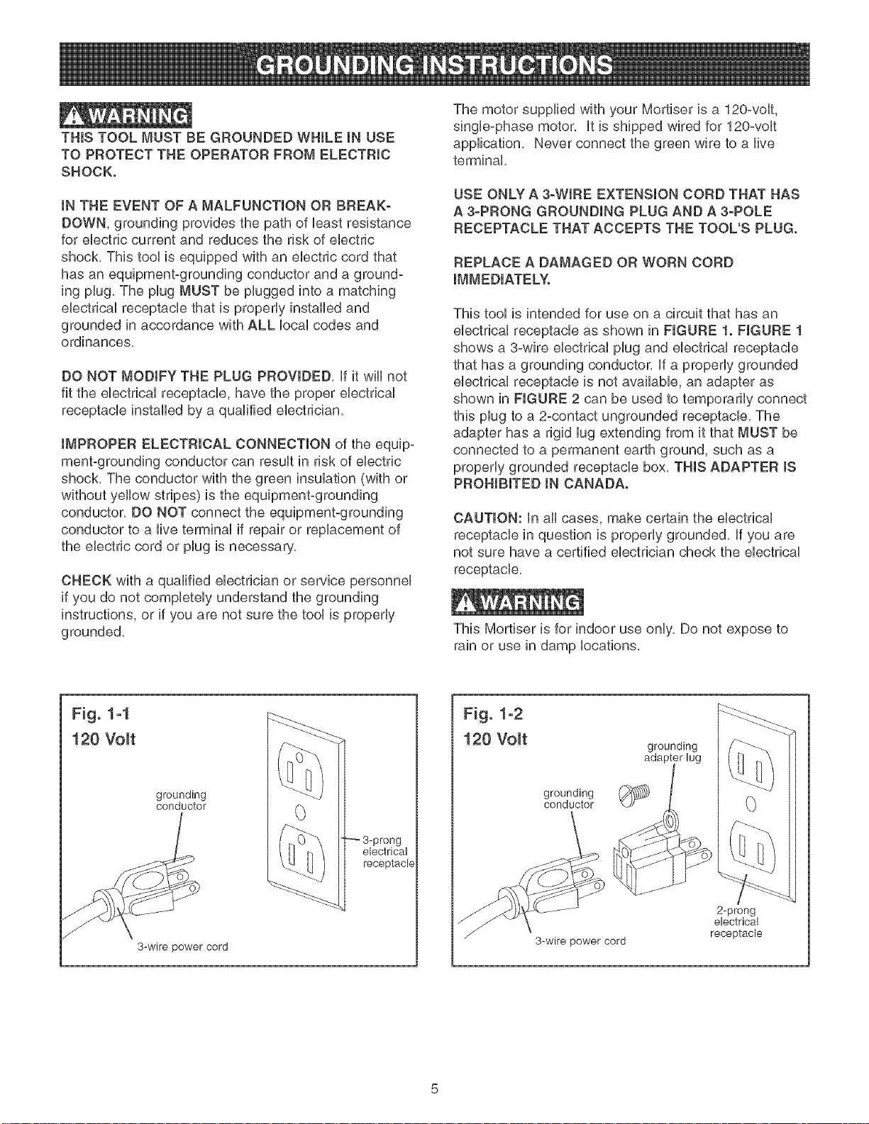
This tool is intended for use on a circuit that has an
electrical receptacle as shown in FIGURE 1. FIGURE 1
shows a 3-wire electrical plug and electrical receptacle
that has a grounding conductor. If a properly grounded
electrical receptacle is not available, an adapter as
shown in FIGURE 2 can be used to temporarily connect
this plug to a 2-contact ungrounded receptacle. The
adapter has a rigid lug extending from it that MUST be
connected to a permanent earth ground, such as a
properly grounded receptacle box. THIS ADAPTER IS
PROHIBITED IN CANADA.
CAUTION: In all cases, make certain the electrical
receptacle in question is properly grounded. If you are
not sure have a certified electrician check the electrical
receptacle.
This Mortiser is for indoor use only, Do not expose to
rain or use in damp locations,
Fig. 1-1
120 Volt
grounding
conductor
3-wire power cord
3-prong
electrical
receptacle
Fig. 1-2
120 Volt
grounding
conductor
3-wire power cord
grounding
2-prong
electrical
receptacle

SPECIFIC SAFETY iNSTRUCTiONS
ALWAYS WEAR EYE PROTECTmON, Any power tool
can throw debris into the eyes during operations, which
could cause severe and permanent eye damage.
Everyday eyeglasses are NOT safety glasses.
ALWAYS wear Safety Goggbs (that comply with ANSi
standard Z87.1) when operating power toob. Safety
Goggbs are availabb at Sears Retaib Stores.
Basic precautions should always be followed when
using any power tool. To reduce the risk of injury,
ebctrbal shock or fire, comply with the safety rubs
listed below:
1. READ and understand the instruction manual
before operating this power tool.
2, DO NOT OPERATE THIS MACHINE until it is
assembled and installed according to the instruc-
tions,
3. OBTAIN ADVICE FROM YOUR SUPERVISOR,
instructor, or another qualified person if you are not
familiar with the operations of this power tool.
4. DO NOT leave any power tool plugged into the
electrical outlet. Unplug it from the outlet when not
in use and before servicing and cleaning.
5, TO REDUCE THE RISK OF ELECTRICAL
SHOCK, do not use outdoors, Do not expose to
rain, Store indoors,
6,
FOLLOW all electrical and safety codes, including
the National Electric Code (NED) and the Occu-
pational Safety and Health Regulations (OSHA).
All electrical connections and wiring should be
made by qualified personnel only.
7. DO NOT handle the plug or mortiser with wet
hands.
8. CONNECT power tool to a properly grounded outlet
only. See grounding instructions.
9, SECURE THE MACHINE TO A SUPPORTING
SURFACE, Vibration can cause the machine to
slide, walk, or tip over,
10, NEVER START THE MACHINE with the drill bit or
cutting tool against the workpiece, Loss of control of
the workpiece can cause serious injury.
11. PROPERLY LOCK THE DRILL BIT OR CUTTING
TOOL IN THE UNIT before operating this machine.
12. ADJUST the depth stop to avoid drilling into the
table.
13. DO NOT attempt to mortise material that does not
have a fiat surface, unless a suitable support is
used.
14.
USE ONLY DRILL BITS, CUTTING TOOLS, OR
OTHER ACCESSORIES with shank size recom-
mended in your instruction manual. The wrong size
accessory can cause damage to the machine
and/or serious injury.
15.
USE ONLY DRILL BITS OR CUTTING TOOLS
that are not damaged. Damaged items can cause
malfunctions that lead to injuries.
16.
ALWAYS position the hold-down directly over the
workpiece to prevent the workpiece from lifting
during operation. Loss of control of the workpiece
can cause serious injury.
17.
TURN THE MACHINE "OFF" AND WAIT FOR
THE DRILL BIT, CUTTING TOOL, OR SANDING
DRUM TO STOP TURNING prior to cleaning the
work area, removing debris, removing or securing
work-piece, or changing the angle of the table, A
moving drill bit or cutting tool can cause serious
injury.
18.
PROPERLY SUPPORT LONG OR WIDE work-
pieces, loss of control of the workpiece can cause
severe injury.
19.
NEVER PERFORM LAYOUT, ASSEMBLY OR
SET-UP WORK on the table/work area when the
machine is running, Serious injury can result,
20.
TURN THE MACHINE "OFF", disconnect the
machine from the power source, and clean the
table/work area before leaving the machine.
REMOVE THE SWITCH KEY to prevent unauthor-
ized use. Someone else might accidentally start the
machine and cause serious injury to themselves.
21.
REPLACE a damaged cord immediately. DO NOT
use a damaged cord or plug. if the power tool is not
operating properly, or has been damaged, left out-
doors or has been in contact with water, return it to
a Sears Service Center.
22.
USE only as described in this manual. USE acces-
sories only recommended by Sears.
23.
ADDITIONAL INFORMATION regarding the safe
and proper operation of this product is available
from the National Safety Council, 1121 Spring Lake
Drive, Itasca, IL 60143-3201 in the Accident
Prevention Manual for Industrial Operation and also
in the Safety Data Sheets provided by the NSC.
Please also refer to the American National
Standards institute ANSi 01.1 Safety Requirements
for Woodworking Machinery and the U.S.
Department of Labor OSHA 1910.213 Regulations.
24.
SAVE THESE INSTRUCTIONS. Refer to them fie-
quently and use them to instruct other users.

AVAILABLE ACCESSORUES
Visit your Sears Hardware Department or see the
Craftsman Power and Hand Tool Catalog for the followo
ing accessories:
iTEM
1/4" Mortising Drill Bit
5/16" Mortising Drill Bit
3/8" Mortising Drill Bit
1/2" Mortising Drill Bit
1/4" Mortising Chisel
5/16" Mortising Chisel
3/8" Mortising Chisel
1/2" Mortising Chisel
STOCK NUMBER
26411
26412
26413
26414
26415
26416
26417
26418
Sears may recommend other accessories not listed in
this manual,
See your nearest Sears Hardware Department or
Craftsman Power and Hand Tool Catalog for other
accessories,
Do not use any accessory unless you have completely
read the instruction Manual for that accessory,
Use only accessories recommended for this mortiser,
Using other accessories may cause serious injury and
cause damage to the mortiser,
UNPACKUNG AND CHECKUNG CONTENTS
This mortiser wiii require some amount of assembly,
Three L handle allen wrenches (8mm, 6mm and 5mm)
and one T handle allen wrench (4mm) are provided for
assembly,
Remove all protective materials and coatings from the
parts, The protective coatings can be removed by
spraying WD°40 on a part and wiping it off with a soft
cloth, This may need to be redone several times before
all of the protective coatings are removed completely,
CAUTmON: DO NOT use acetone, gasoline or lacquer
thinner to remove any protective coatings,
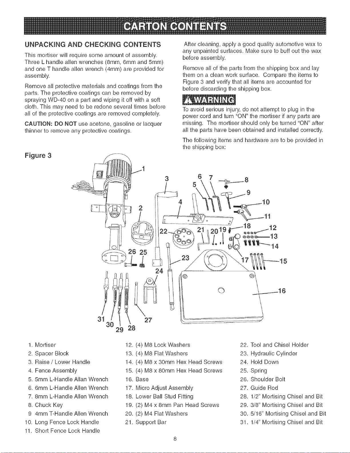
Figure 3
2
After cleaning, apply a good quality automotive wax to
any unpainted surfaces, Make sure to buff out the wax
before assembly,
Remove all of the parts from the shipping box and lay
them on a dean work surface, Compare the items to
Figure 3 and verify that all items are accounted for
before discarding the shipping box,
To avoid serious injury, do not attempt to plug in the
power cord and turn "ON" the mortiser if any parts are
missing, The mortiser should only be turned "ON" after
all the parts have been obtained and installed correctly,
The following items and hardware are to be provided in
the shipping box:
4
1, Mortiser
2, Spacer Block
3, Raise / Lower Handle
4, Fence Assembly
5, 5ram L-Handle Allan Wrench
6, 6ram L-Handle Allen Wrench
7, 8ram L-Handle Allen Wrench
8, Chuck Key
9 4ram ToHandle Allen Wrench
10, Long Fence Lock Handle
11, Short Fence Lock Handle
26 25
24
3!1
30
29
12, (4) M8 Lock Washers
13, (4) M8 Fiat Washers
14, (4) M8 x 30mm Hex Head Screws
15, (4) M8 x 80mm Hex Head Screws
16, Base
17, Micro Adjust Assembly
18, Lower Ball Stud Fitting
19, (2) M4 x 8mm Pan Head Screws
20, (2) M4 Fiat Washers
21, Support Bar
27
28
©
22, Tool and Chisel Holder
23, Hydraulic Cylinder
24, Hold Down
25, Spring
26, Shoulder Bolt
27, Guide Rod
28, 1/2" Mortising Chisel and Bit
29, 3/8" Mortising Chisel and Bit
30, 5/16" Mortising Chisel and Bit
31, 1/4" Mortising Chisel and Bit
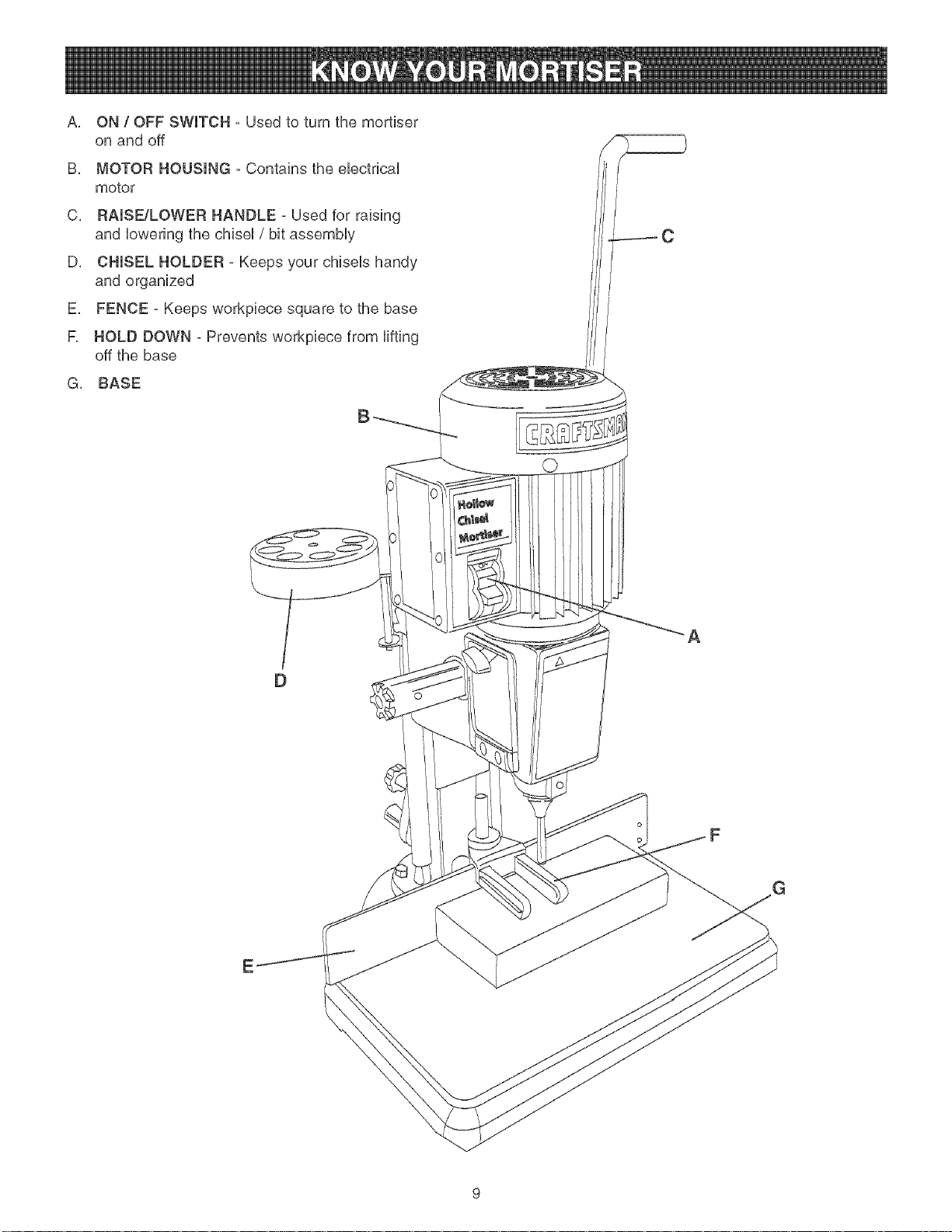
A, ON/ OFF SWITCH - Used to turn the mortiser
on and off
B, MOTOR HOUSING - Contains the eUectdcaU
motor
C, RAISE/LOWER HANDLE - Used for raising
and Uowedng the chiseU/ bit assemMy
D, CHISEL HOLDER - Keeps your chiseUs handy
and organized
E, FENCE - Keeps workpiece square to the base
F, HOLD DOWN - Prevents workpiece from Hfting
off the base
G, BASE
B
A
o
F
E
Four different size allen wrenches are provided to assist BASE ASSEMBLY
in the assemMy of the Mortiser,
Make sure that the machine is disconnected from the
1, DO NOT assembb the Mortiser until you are sure
powe r sou rce,
the tooUis disconnected from the power source,
2, DO NOT assembb the Mortiser until you are sure
Figure 6
the power switch is in the off position,
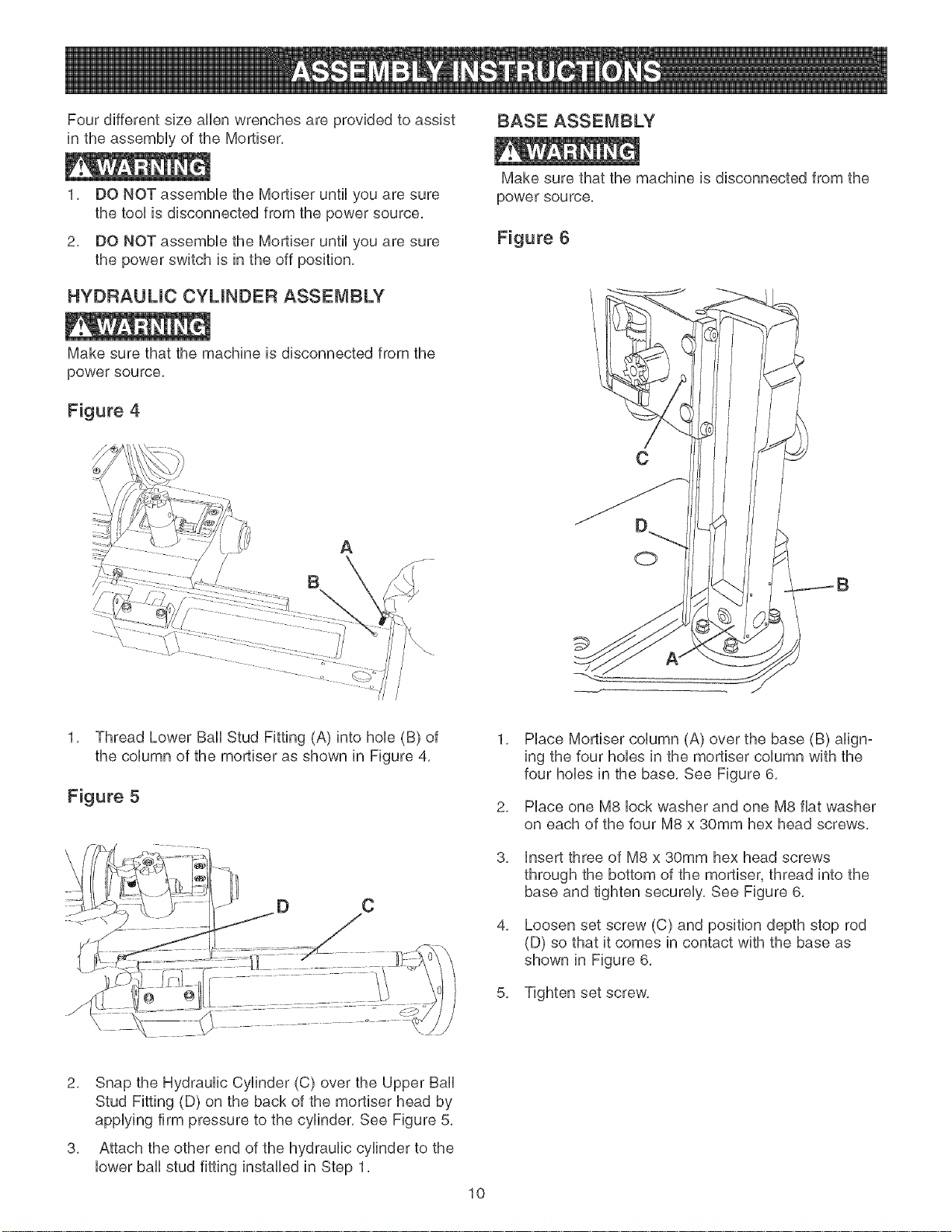
HYDRAULIC CYLINDER ASSEMBLY
Make sure that the machine is disconnected from the
power source,
Figure 4
\
C
A
B
i
/
/
/
1, Thread Lower Ball Stud Fitting (A) into hob (B) of
the column of the mortiser as shown in Figure 4,
Figure 5
C
0
1,
Place Mortiser column (A) over the base (B) align-
ing the four hobs in the mortiser column with the
four hobs in the base, See Figure 6,
2,
Place one M8 lock washer and one M8 fiat washer
on each of the four M8 x 30mm hex head screws,
3,
insert three of M8 x 30mm hex head screws
through the bottom of the mortiser, thread into the
base and tighten securely, See Figure 6,
4,
Loosen set screw (C) and position depth stop rod
(D) so that it comes in contact with the base as
shown in Figure 6,
5, Tighten set screw,
2, Snap the Hydraulic Cylinder (C) over the Upper Ball
Stud Fitting (D) on the back of the mortiser head by
applying firm pressure to the cylinder, See Figure 5,
3, Attach the other end of the hydraulic cylinder to the
lower ball stud fitting installed in Step 1,
10
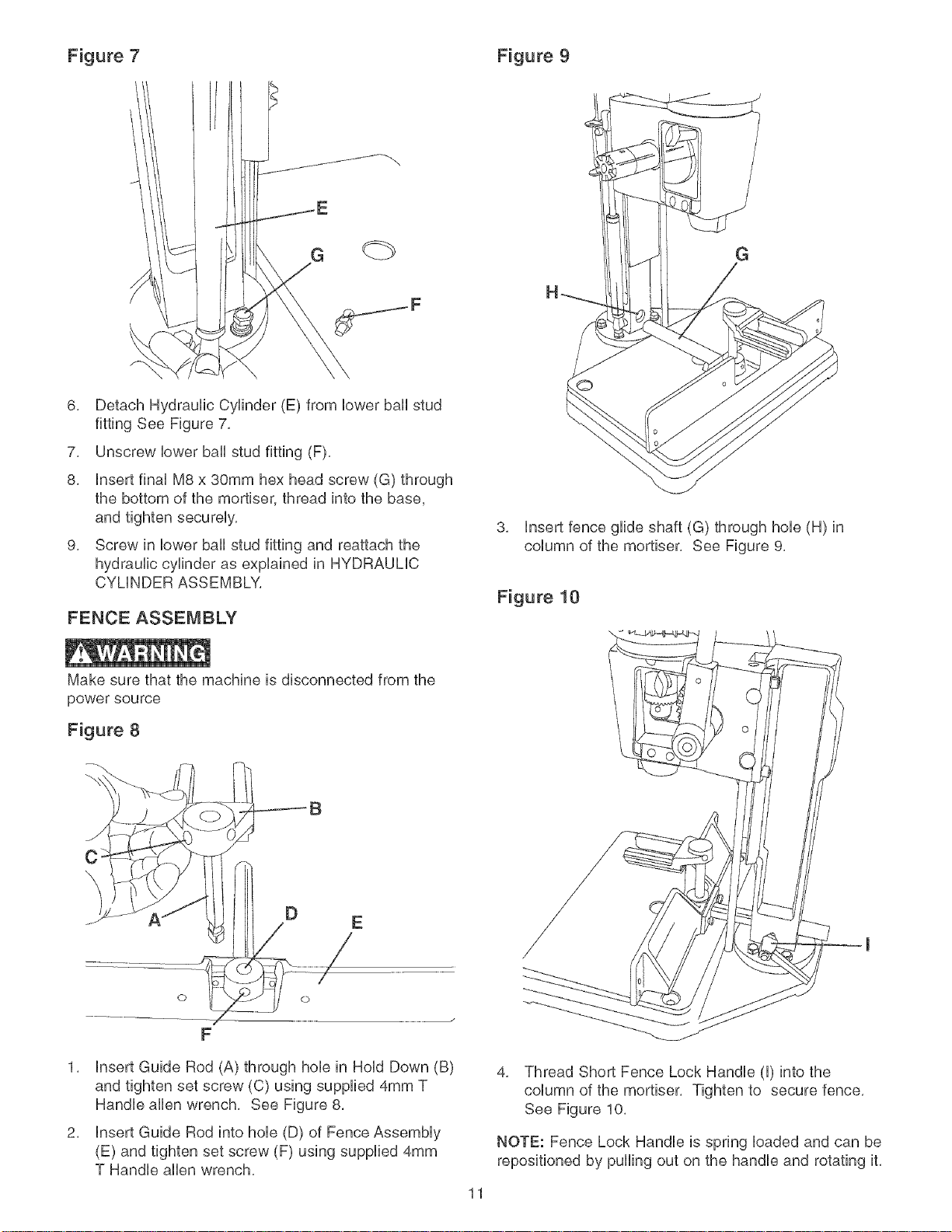
Figure 7 Figure 9
G
\
6, Detach Hydraufic Cyfinder (E) from bwer bah stud
fitting See Figure 7,
7, Unscrew bwer bail stud fitting (F),
8, insert finaUM8 x 30mm hex head screw (G) through
the bottom of the mortiser, thread into the base,
and tighten secureUy,
9, Screw in bwer bail stud fitting and reattach the
hydraulic cylinder as expUained in HYDRAUMC
CYMNDER ASSEMBLY,
FENCE ASSEMBLY
Make sure that the machine is disconnected from the
power source
G
3, Insert fence glide shaft (G) through hole (H) in
column of the mortiser, See Figure 9,
Figure 10
\
Figure 8
C
\
E
F
1, insert Guide Rod (A) through hob in HoUdDown (B)
and tighten set screw (C) using supplied 4mm T
Handb aflen wrench, See Figure 8,
2, insert Guide Rod into hob (D) of Fence AssemMy
(E) and tighten set screw (F) using supplied 4mm
T Handle allen wrench,
4. Thread Short Fence Lock Handle (I) into the
column of the mortiser. Tighten to secure fence.
See Figure 10.
NOTE: Fence Lock Handle is spring loaded and can be
repositioned by puffing out on the handle and rotating it,
11
MICF{O ADJUST ASSEMBLY F_AISUNG / LOWERING HANDLE
Make sure that the machine is disconnected from the
power source.
Figure 11
Make sure that the machine is disconnected from the
powe r sou rce,
Figure 12
A
C
D c
B
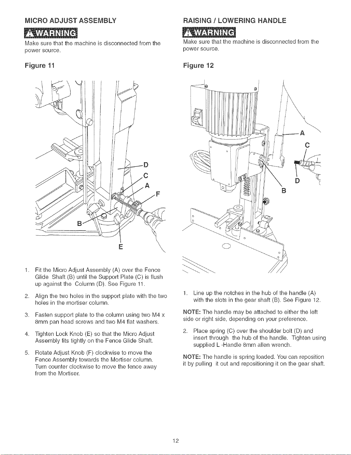
Fit the Micro Adjust Assembly (A) over the Fence
Glide Shaft (B) until the Support Hate (C) is flush
up against the Column (D), See Figure 11,
2,
Align the two hobs in the support plate with the two
hobs in the mortiser column,
3,
Fasten support plate to the column using two M4 x
8mm pan head screws and two M4 fiat washers,
4,
Tighten Lock Knob (E) so that the Micro Adjust
Assembly fits tightly on the Fence Glide Shaft,
5,
Rotate Adjust Knob (F) clockwise to move the
Fence Assembly towards the Mortiser column,
Turn counter clockwise to move the fence away
from the Mortiser,
1, Line up the notches in the hub of the handle (A)
with the slots in the gear shaft (B), See Figure 12,
NOTE: The handle may be attached to either the left
side or right side, depending on your preference,
2, Place spring (C) over the shoulder bolt (D) and
insert through the hub of the handle, Tighten using
supplied L =Handle 8mm allen wrench,
NOTE: The handle is spring loaded, You can reposition
it by pulling it out and repositioning it on the gear shaft,
12
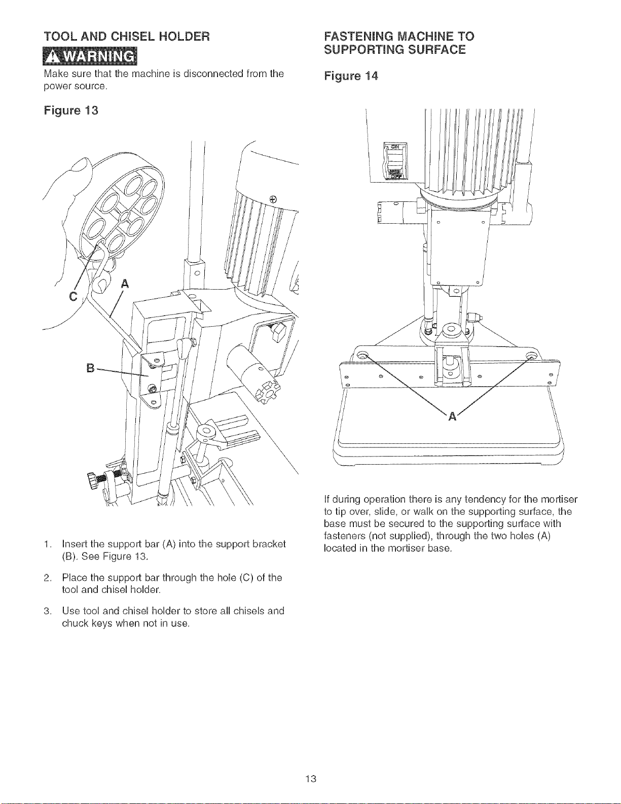
TOOL AND CHUSEL HOLDER FASTENING MACHINE TO
SUPPORTING SURFACE
Make sure that the machine is disconnected from the
power source,
Figure 13
®
C
Figure 14
insert the support bar (A) into the support bracket
(B), See Figure 13,
2,
PUacethe support bar through the hob (C) of the
tooUand chbeU hoUder,
3,
Use tool and chisel holder to store all chisels and
chuck keys when not in use,
\
\
\,
,__ J
if during operation there is any tendency for the mortiser
to tip over, slide, or walk on the supporting surface, the
base must be secured to the supporting surface with
fasteners (not supplied), through the two hobs (A)
located in the mortiser base,
13
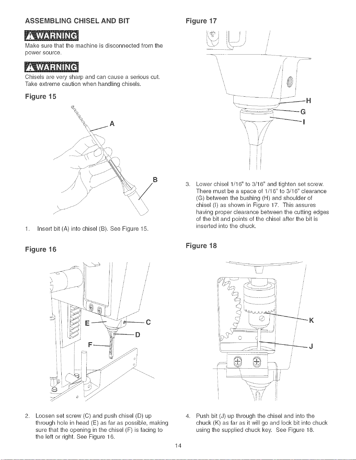
ASSEMBLING CHUSEL AND BIT
Make sure that the machine is disconnected from the
power source.
ChbeUs are very sharp and can cause a serious cut.
Take extreme caution when handling chiseUs.
Figure 15
Figure 17
/J //
/ / _'i
1. Insert bit (A) into chisel (B). See Figure 15.
Figure 16
} /
/
/
/
/
J
/
E
B
3,
Lower chiseU1/16" to 3/16" and tighten set screw.
There must be a space of 1/16" to 3/16" cbarance
(G) between the bushing (H) and shouUder of
chiseU(U)as shown in Figure 17. This assures
having proper clearance between the cutting edges
of the bit and points of the chiseUafter the bit is
inserted into the chuck.
Figure 18
/
/
/
/
/
C
/
/
K
2,
Loosen set screw (C) and push chisel (D) up
through hole in head (E) as far as possible, making
sure that the opening in the chisel (F) is facing to
the left or right. See Figure 16.
14
[
[
[
i
[
[
4,
Push bit (J) up through the chisel and into the
chuck (K) as far as it will go and lock bit into chuck
using the supplied chuck key, See Figure 18,
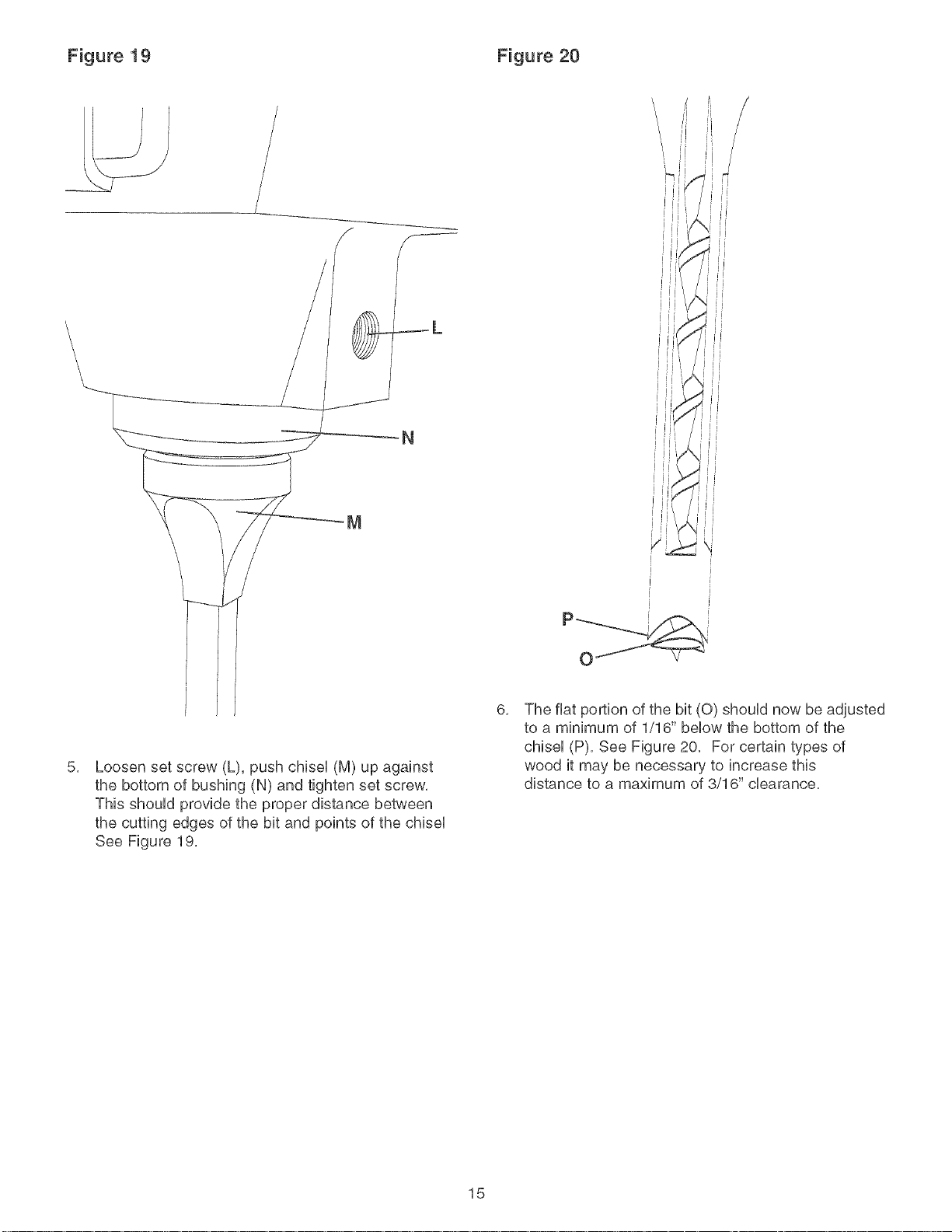
Figure 19 Figure 20
\
\
\
\
\
5,
Loosen set screw (L), push chiseU (M) up against
the bottom of bushing (N) and tighten set screw,
This shouUd provide the proper distance between
the cutting edges of the bit and points of the chiseU
See Figure 19,
_L
N
i
i
i
6,
The fiat portion of the bit (0) shouUd now be adjusted
to a minimum of 1/16" beUowthe bottom of the
chiseU(P), See Figure 20, For certain types of
wood it may be necessary to increase this
distance to a maximum of 3/16" clearance,
15
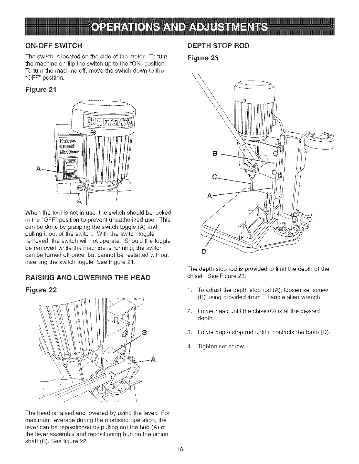
ON-OFF SWITCH
DEPTH STOP ROD
The switch is Uocatedon the side of the motor, To turn
the machine on flip the switch up to the "ON" position,
To turn the machine off, move the switch down to the
"OFF" position,
Figure 21
@
A_
When the tooUis not in use, the switch shouUd be Uocked
in the "OFF" position to prevent unauthorized use, This
can be done by grasping the switch toggUe (A) and
pulling it out of the switch, With the switch toggUe
removed, the switch wHUnot operate, ShouUdthe toggUe
be removed while the machine is running, the switch
can be turned off once, but cannot be restarted without
inserting the switch toggUe, See Figure 21,
RAISUNG AND LOWERUNG THE HEAD
Figure 23
A
The depth stop rod is provided to Hmit the depth of the
chisel, See Figure 23,
Figure 22
B
The head is raised and lowered by using the lever, For
maximum leverage during the mortising operation, the
lever can be repositioned by pulling out the hub (A) of
the lever assembly and repositioning hub on the pinion
shaft (B), See figure 22,
1,
To adjust the depth stop rod (A), loosen set screw
(B) using provided 4mm T handle allen wrench,
2,
Lower head until the chisel(C) is at the desired
depth,
3, Lower depth stop rod until it contacts the base (D),
4, Tighten set screw,
16
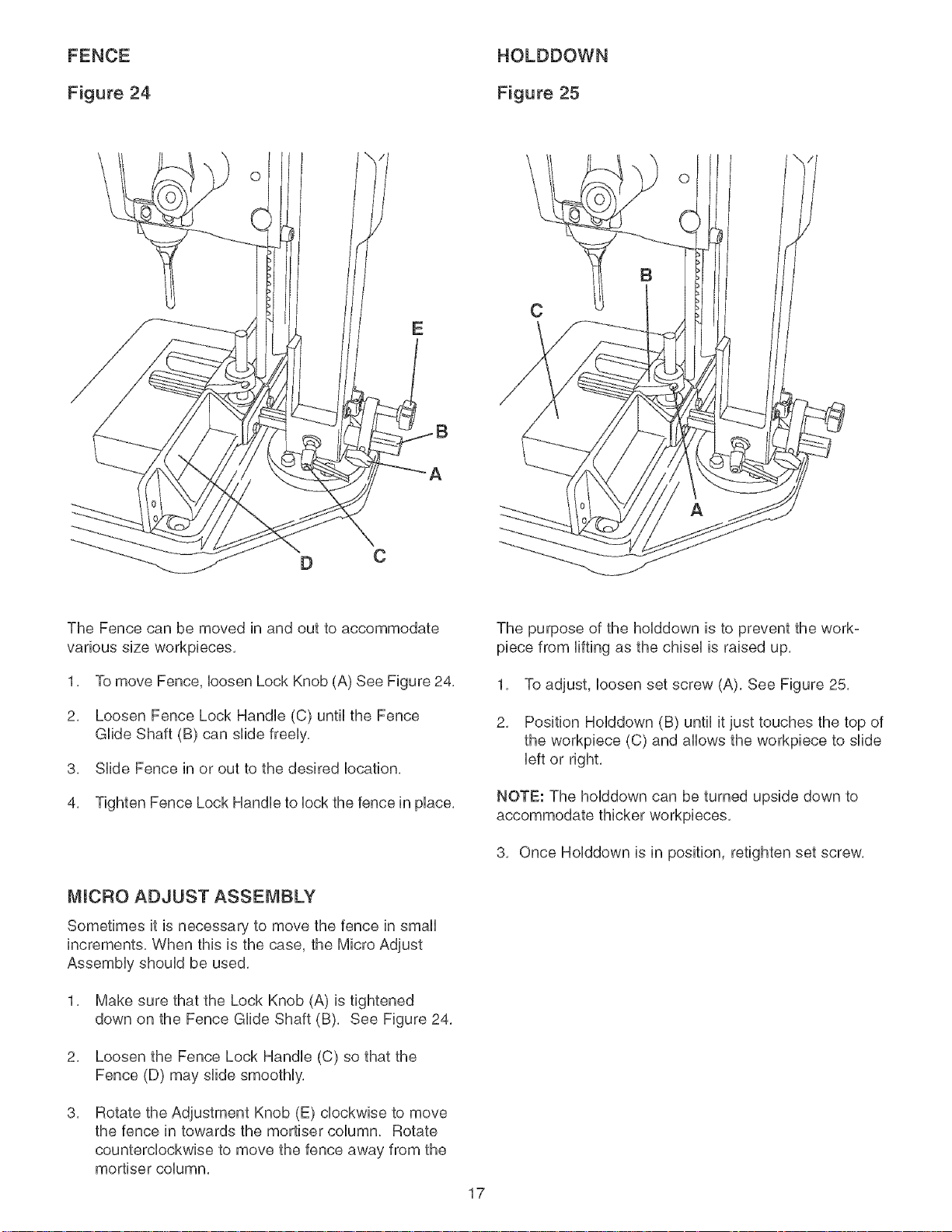
FENCE
HOLDDOWN
Figure 24
\
Figure 25
O
O
C
C
The Fence can be moved in and out to accommodate
various size workpbces,
1, To move Fence, bosen Lock Knob (A) See Figure 24,
2, Loosen Fence Lock Handb (C) until the Fence
GUideShaft (B) can slide freeUy,
3, SHde Fence in or out to the desired bcation,
4, Tighten Fence Lock Handb to bck the fence in pUace,
MICRO ADJUST ASSEMBLY
Sometimes it is necessary to move the fence in small
increments, When this is the case, the Micro Adjust
AssemMy shouUd be used,
1, Make sure that the Lock Knob (A) is tightened
down on the Fence GUideShaft (B), See Figure 24,
The purpose of the holddown is to prevent the work-
piece from lifting as the chisel is raised up,
1, To adjust, loosen set screw (A), See Figure 25,
2, Position HoUddown (B) until it just touches the top of
the workpbce (C) and allows the workpbce to slide
left or right,
NOTE: The holddown can be turned upside down to
accommodate thicker workpieces,
3, Once Holddown is in position, retighten set screw,
2, Loosen the Fence Lock Handb (C) so that the
Fence (D) may slide smootHy,
3,
Rotate the Adjustment Knob (E) clockwise to move
the fence in towards the mortiser column, Rotate
counterclockwise to move the fence away from the
mortiser column,
17
 Loading...