

Craftsman 152217060 Owner’s Manual

Owner's Manual
iCRnFrSMnN'i
iPROFESSIONAI
6-1/8-in. Wide
1 Horsepower (continuous duty)
5000 Cutterhead R.P.M. (no load speed)
6-1/8-in.
JOINTER-PLANER
Model No.
152.217060
c
CAUTION:
FOR YOUR OWN SAFETY read
and follow all of the Safety and
Operating Instructions before
operating this Jointer/Planer.
Customer Helpline
1-800-897-7709
Please have your Model No.
and Serial No.available.
Sears, Roebuck and Co., Hoffman Estates, IL 60179 U.S.A.
Part No. OR90365
Revised 6-13-03
Espa_ol, p. 27
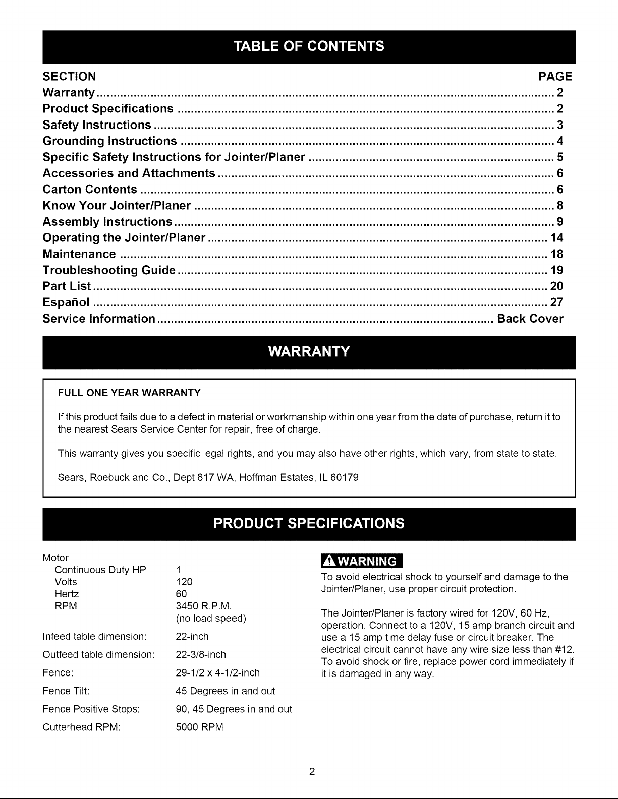
SECTION PAGE
Warranty ........................................................................................................................................ 2
Product Specifications ................................................................................................................ 2
Safety Instructions ....................................................................................................................... 3
Grounding Instructions ............................................................................................................... 4
Specific Safety Instructions for Jointer/Planer ......................................................................... 5
Accessories and Attachments .................................................................................................... 6
Carton Contents ........................................................................................................................... 6
Know Your Jointer/Planer ........................................................................................................... 8
Assembly Instructions ................................................................................................................. 9
Operating the Jointer/Planer ..................................................................................................... 14
Maintenance ............................................................................................................................... 18
Troubleshooting Guide .............................................................................................................. 19
Part List ....................................................................................................................................... 20
EspaSol ....................................................................................................................................... 27
Service Information .................................................................................................... Back Cover
FULL ONE YEAR WARRANTY
If this product fails due to a defect in material or workmanship within one year from the date of purchase, return it to
the nearest Sears Service Center for repair, free of charge.
This warranty gives you specific legal rights, and you may also have other rights, which vary, from state to state.
Sears, Roebuck and Co., Dept 817 WA, Hoffman Estates, IL 60179
Motor
Continuous Duty HP 1
Volts 120
Hertz 60
RPM 3450 R.P.M.
(no load speed)
Infeed table dimension: 22-inch
Outfeed table dimension: 22-3/8-inch
Fence: 29-1/2 x 4-1/2-inch
Fence Tilt: 45 Degrees in and out
r!Vivhl _1_II _[€'ll
To avoid electrical shock to yourself and damage to the
Jointer/Planer, use proper circuit protection.
The Jointer/Planer is factory wired for 120V, 60 Hz,
operation. Connect to a 120V, 15 amp branch circuit and
use a 15 amp time delay fuse or circuit breaker. The
electrical circuit cannot have any wire size less than #12.
To avoid shock or fire, replace power cord immediately if
it is damaged in any way.
Fence Positive Stops: 90, 45 Degrees in and out
Cutterhead RPM: 5000 RPM
2

GENERAL SAFETY INSTRUCTIONS
Operating a Jointer/Planer can be dangerous if
safety and common sense are ignored. The
operator must be familiar with the operation of the
tool. Read this manual to understand this Jointeri
Planer. DO NOT operate this Jointer/Planer if you
do not fully understand the limitations of this tool.
DO NOT modify this Jointer/Planer in any way.
BEFORE USING THE JOINTER/PLANER
_!Vivlzl t,_l_II _[e'll
To avoid serious injury and damage to the tool, read and
follow all of the Safety and Operating Instructions before
operating the Jointer/Planer.
1. READ the entire Owner's Manual. LEARN how to
use the tool for its intended applications.
.
GROUND ALL TOOLS. If the tool is supplied with a
3-prong plug, it must be plugged into a 3-contact
electrical receptacle. The 3rd prong is used to
ground the tool and provide protection against
accidental electric shock. DO NOT remove the 3rd
prong. See Grounding Instructions on page 4.
3. AVOID A DANGEROUS WORKING
ENVIRONMENT. DO NOT Use electrical tools in a
damp environment or expose them to rain.
4. DO NOT use electrical tools in the presence of
flammable liquids or gasses.
.
ALWAYS keep the work area clean, well lit, and
organized. DO NOT work in an environment with
floor surfaces that are slippery from debris, grease
or wax.
.
KEEP VISITORS AND CHILDREN AWAY. DO NOT
permit people to be in the immediate work area,
especially when the electrical tool is operating.
.
DO NOT FORCE THE TOOL to perform an
operation for which it was not designed. It will do a
safer and higher quality job by only performing
operations for which the tool was intended.
.
WEAR PROPER CLOTHING. DO NOT wear loose
clothing, gloves, neckties, or jewelry. These items
can get caught in the machine during operations and
pull the operator into the moving parts. The user
must wear a protective cover on their hair, if the hair
is long, to prevent it from contacting any moving
parts.
.
ALWAYS WEAR EYE PROTECTION. Any power
tool can throw debris into the eyes during
operations, which could cause severe and
permanent eye damage. ALWAYS Wear Safety
Goggles (that comply with ANSI standard Z87.1)
when operating power tools. Safety Goggles are
available at Sears Retail Stores.
10.
WEAR A DUST MASK TO PREVENT INHALING
DANGEROUS DUST OR PARTICLES.
11.
ALWAYS UNPLUG THE TOOL FROM THE ELEC-
TRICAL RECEPTACLE when making adjustments,
changing parts or performing any maintenance.
12.
KEEP PROTECTIVE GUARDS IN PLACE AND IN
WORKING ORDER.
13.
AVOID ACCIDENTAL STARTING. Make sure that
the power switch is in the "OFF" position before
plugging in the power cord to the electrical
receptacle.
14.
REMOVE ALL MAINTENANCE TOOLS from the
immediate area prior toturning "ON" the Jointer/Planer.
15.
USE ONLY RECOMMENDED ACCESSORIES. Use
of incorrect or improper accessories could cause
serious injury to the operator and cause damage to
the tool. If in doubt, check the instruction manual
that comes with that particular accessory.
16.
NEVER LEAVE A RUNNING TOOL
UNATTENDED. Turn the power switch to the "OFF"
position. DO NOT leave the tool until it has come to
a complete stop.
17.
DO NOT STAND ON A TOOL. Serious injury could
result if the tool tips over or you accidentally contact
the tool.
18.
DO NOT store anything above or near the tool
where someone might try to stand on the tool to
reach it.
19.
MAINTAIN YOUR BALANCE. DO NOT extend yourself
over the tool. Wear oil resistant, rubber-soled shoes.
Keep floor clear of debris, grease, and wax.
20.
MAINTAIN TOOLS WITH CARE. Always keep tools
clean and in good working order. Keep all blades
and tool bits sharp.
SAVE THESE INSTRUCTIONS.
3
21.EACHAND EVERY TIME, CHECK FOR
DAMAGED PARTS PRIOR TO USING THE TOOL.
Carefully check all guards to see that they operate
properly, are not damaged, and perform their
intended functions. Check for alignment, binding or
breaking of moving parts. A guard or other part that
is damaged should be immediately repaired or
replaced.
22. CHILDPROOF THE WORKSHOP AREA by
removing switch keys, unplugging tools from the
electrical receptacles, and using padlocks.
23. DO NOT OPERATE TOOL IF UNDER THE INFLU-
ENCE OF DRUGS OR ALCOHOL.
24. SECURE ALL WORK. When it is possible, use
clamps or jigs to secure the workpiece. This is safer
than attempting to hold the workpiece with your
hands.
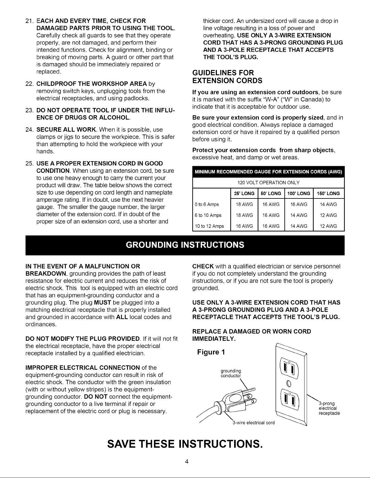
25. USE A PROPER EXTENSION CORD IN GOOD
CONDITION. When using an extension cord, be sure
to use one heavy enough to carry the current your
product will draw. The table below shows the correct
size to use depending on cord length and nameplate
amperage rating. If in doubt, use the next heavier
gauge. The smaller the gauge number, the larger
diameter of the extension cord. If in doubt of the
proper size of an extension cord, use a shorter and
thicker cord. An undersized cord will cause a drop in
line voltage resulting in a loss of power and
overheating. USE ONLY A 3-WIRE EXTENSION
CORD THAT HAS A 3-PRONG GROUNDING PLUG
AND A 3-POLE RECEPTACLE THAT ACCEPTS
THE TOOL'S PLUG.
GUIDELINES FOR
EXTENSION CORDS
If you are using an extension cord outdoors, be sure
it is marked with the suffix "W-A" ("W" in Canada) to
indicate that it is acceptable for outdoor use.
Be sure your extension cord is properly sized, and in
good electrical condition. Always replace a damaged
extension cord or have it repaired by a qualified person
before using it.
Protect your extension cords from sharp objects,
excessive heat, and damp or wet areas.
120 VOLT OPERATION ONLY
0 to 6 Amps
6 to 10 Amps
10to 12 Amps
25' LONG
18 AWG
18 AWG
16 AWG
60' LONG
16 AWG
16 AWG
16 AWG
100' LONG
16 AWG
14 AWG
14 AWG
150' LONG
14 AWG
12 AWG
12 AWG
IN THE EVENT OF A MALFUNCTION OR
BREAKDOWN, grounding provides the path of least
resistance for electric current and reduces the risk of
electric shock. This tool is equipped with an electric cord
that has an equipment-grounding conductor and a
grounding plug. The plug MUST be plugged into a
matching electrical receptacle that is properly installed
and grounded in accordance with ALL local codes and
ordinances.
DO NOT MODIFY THE PLUG PROVIDED. If it will not fit
the electrical receptacle, have the proper electrical
receptacle installed by a qualified electrician.
IMPROPER ELECTRICAL CONNECTION of the
equipment-grounding conductor can result in risk of
electric shock. The conductor with the green insulation
(with or without yellow stripes) is the equipment-
grounding conductor. DO NOT connect the equipment-
grounding conductor to a live terminal if repair or
replacement of the electric cord or plug is necessary.
CHECK with a qualified electrician or service personnel
if you do not completely understand the grounding
instructions, or if you are not sure the tool is properly
grounded.
USE ONLY A 3-WIRE EXTENSION CORD THAT HAS
A 3-PRONG GROUNDING PLUG AND A 3-POLE
RECEPTACLE THAT ACCEPTS THE TOOL'S PLUG.
REPLACE A DAMAGED OR WORN CORD
IMMEDIATELY.
Figure 1
grounding
conductor
0
3-prong
electrical
receptacle
3-wire electrical cord
SAVE THESE INSTRUCTIONS.
4

Figure 2
grounding
conductor
__m _trical cord
grounding
adapter lug
2-prong
electrical receptacle
This tool is intended for use on a circuit that has an
electrical receptacle as shown in FIGURE 1. FIGURE 1
shows a 3-wire electrical plug and electrical receptacle
that has a grounding conductor. If a properly grounded
electrical receptacle is not available, an adapter as
shown in FIGURE 2 can be used to temporarily connect
this plug to a 2-contact ungrounded receptacle. The
adapter has a rigid lug extending from it that MUST be
connected to a permanent earth ground, such as a
properly grounded receptacle box. THIS ADAPTER IS
PROHIBITED IN CANADA.
CAUTION: In allcases, make certain the electrical receptacle
in question is properly grounded. If you are not sure, have a
certified electrician check the electrical receptacle.
F'!,vlv/:1;3 _11_[ell
This Jointer/Planer isfor indoor use only. To avoid electrical
shock, do not expose to rain or use in damp locations.
SPECIFIC SAFETY INSTRUCTIONS
FOR JOINTER/PLANER
The operation of any Jointer/Planer can result in debris
being thrown into your eyes, which can result in severe
eye damage. ALWAYS wear Safety Goggles (that comply
with ANSI standard Z87.1) when operating the Jointeri
Planer. Safety Goggles are available at Sears Retail
Stores. Keep your thumbs and fingers away from the
cutterhead.
,
WARNING: Do not operate the Jointer/Planer until it is
completely assembled and installed according to the
instructions.
2. IF YOU ARE NOT thoroughly familiar with the
operation of Jointers/Planers, obtain advice from your
supervisor, instructor or other qualified person.
3. KEEP cutterhead knives sharp and freeof all rustandpitch.
4. BEFORE starting machine, check cutterhead guard to
make sure it is not damaged and operates freely.
5. ALWAYS make sure exposed cutterhead behind the
fence is guarded, especially when jointing near the
edge.
6. NEVER perform jointing or planing operations with the
cutterhead guard removed.
7. MAKE CERTAIN the infeed and outfeed tables are
tightened before starting the machine.
,
NEVER start the jointer with the workpiece contacting
the cutterhead.
9.
ALWAYS hold the workpiece firmly against the tables
and fence.
10.
NEVER perform any operations "FREE-HAND" which
means usingyour hands tosupport orguide theworkpiece.
ALWAYS use the fence to position and guide the work.
11.
AVOID awkward operations and hand positions where
a sudden slip could cause your hand to move into the
cutterhead.
12.
ALWAYS use hold-down/push blocks for jointing
material less than 3 inches in height or planing
material thinner than 3 inches.
13.
DO NOT perform jointing operations on material
shorter than 10 inches, narrower than 3/4 inch or less
than 1/2 inch thick.
14.
DO NOT perform planing operations on material
shorter than 10 inches, narrower than 3/4 inch or less
than 1/2 inch thick.
15. NEVER make jointing or planing cuts deeper than
1/8 inch. On cuts more than 1 1/2 inches wide, adjust
depth of cut to 1/16 inch or less to avoid overloading
machine and to minimize chance of kickback (work
thrown back toward you).
16. MAINTAIN the proper height between the outfeed
table surface and the cutting circle of the knives.
17. SUPPORT the workpiece adequately at all times during
operation; maintain control of the work at all times.
18. DO NOT back the workpiece over the cutterhead
toward the infeed table.
19.
DO NOT attempt to perform an abnormal or little-used
operation without study and the use of adequate hold-
down/push blocks, jigs, fixtures, stops, push blocks, etc.
20. SHUT OFF power before adjusting jointer.
21. DlSCONNECTJointer/Planerfrom powersource before
servicing and clean the machine before leaving it.
22. MAKE SURE the work area is clean before leaving
the machine.
23.
SHOULD any part of your jointer be missing, dam-
aged, or fail in any way, or any electrical component
fail to perform properly, shut off switch and remove
plug from power supply outlet. Replace missing,
damaged or failed parts before resuming operation.
24. THE USE of attachments and accessories not recom-
mended may result in the risk of injuries.
25. ADDITIONAL INFORMATION regarding the safe and
proper operation of this product is available from the
National Safety Council, 1121 Spring Lake Drive,
Itasca, IL60143-3201 intheAccident Prevention Manual
for Industrial Operations and also in the Safety Data
Sheets provided by the NSC. Please also refer to the
American National Standard Institute ANSI 01.1 Safety
Requirements for Woodworking Machinery and the U.S.
Department of Labor OSHA 1910.213 Regulations.
26. SAVE THESE INSTRUCTIONS. Refer to them often
and use them to instruct others.
5
AVAILABLE ACCESSORIES
Visit your Sears Hardware Department or see the Sears
Power and Hand Tool Catalog for the following
accessories.
ITEM
Replacement Knives
Replacement Push Blocks
Dust Collection Reducer Kit
4" to 21/2''
Sears may recommend other accessories not listed in
this manual.
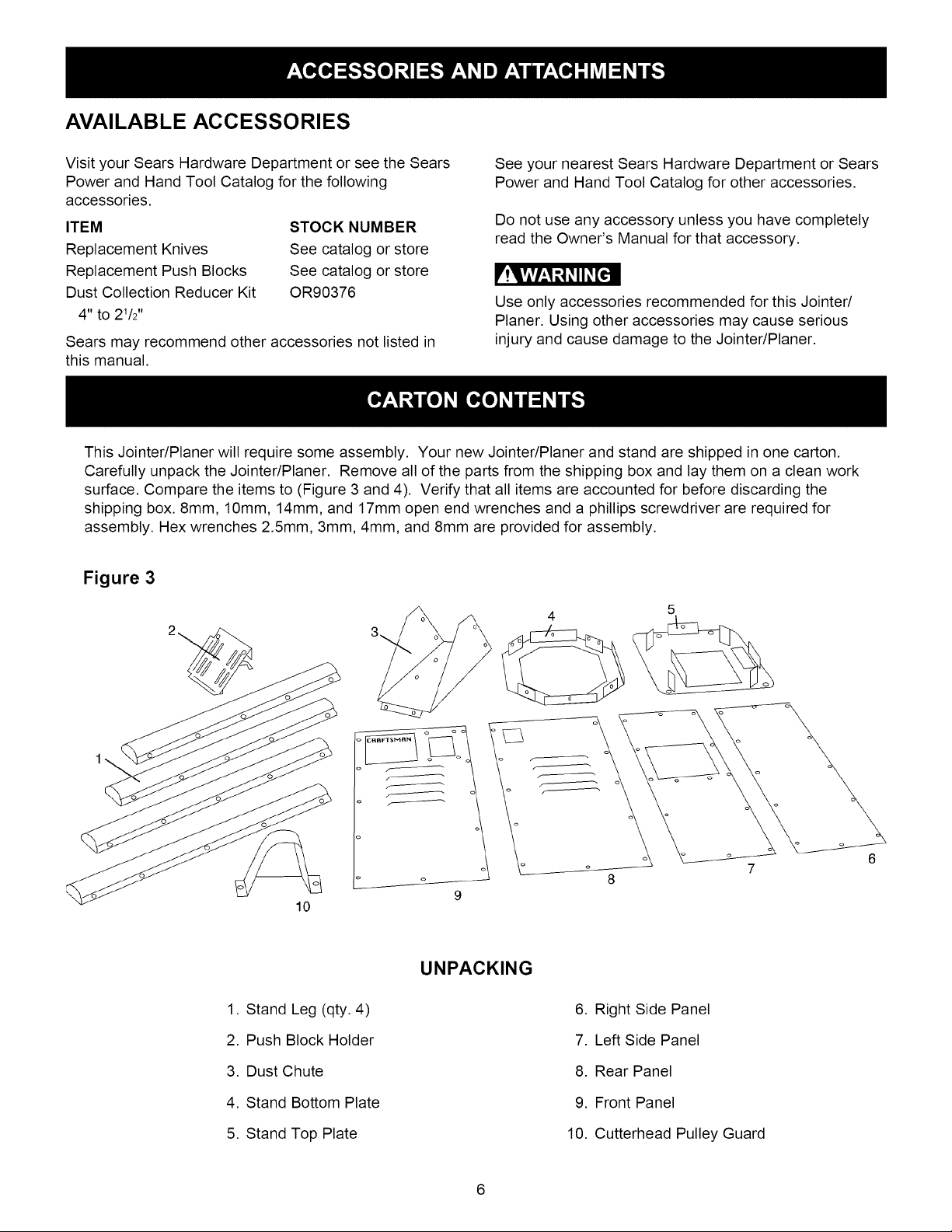
This Jointer/Planer will require some assembly. Your new Jointer/Planer and stand are shipped in one carton.
Carefully unpack the Jointer/Planer. Remove all of the parts from the shipping box and lay them on a clean work
surface. Compare the items to (Figure 3 and 4). Verify that all items are accounted for before discarding the
shipping box. 8mm, 10mm, 14mm, and 17mm open end wrenches and a phillips screwdriver are required for
assembly. Hex wrenches 2.5mm, 3mm, 4mm, and 8mm are provided for assembly.
STOCK NUMBER
See catalog or store
See catalog or store
OR90376
See your nearest Sears Hardware Department or Sears
Power and Hand Tool Catalog for other accessories.
Do not use any accessory unless you have completely
read the Owner's Manual for that accessory.
r!q, viV_,1:_1_II _[€'ll
Use only accessories recommended for this Jointer/
Planer. Using other accessories may cause serious
injury and cause damage to the Jointer/Planer.
Figure 3
5
10
1. Stand Leg (qty. 4)
2. Push Block Holder
3. Dust Chute
4. Stand Bottom Plate
5. Stand Top Plate
UNPACKING
6. Right Side Panel
7. Left Side Panel
8. Rear Panel
9. Front Panel
10. Cutterhead Pulley Guard
6
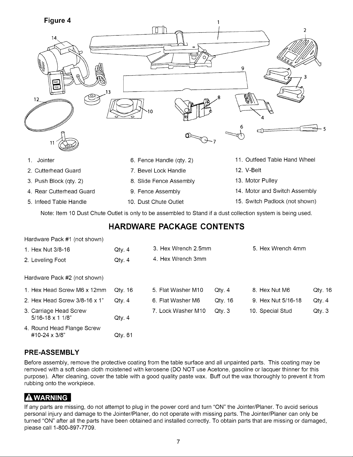
Figure 4 1
6
1. Jointer
2. Cutterhead Guard
3. Push Block (qty. 2)
4. Rear Cutterhead Guard
5. Infeed Table Handle
Note: Item 10 Dust Chute Outlet is only to be assembled to Stand if a dust collection system is being used.
6. Fence Handle (qty. 2)
7. Bevel Lock Handle
8. Slide Fence Assembly
9. Fence Assembly
10. Dust Chute Outlet
11. Outfeed Table Hand Wheel
12. V-Belt
13. Motor Pulley
14. Motor and Switch Assembly
15. Switch Padlock (not shown)
HARDWARE PACKAGE CONTENTS
Hardware Pack #1 (not shown)
1. Hex Nut 3/8-16 Qty. 4
2. Leveling Foot Qty. 4
Hardware Pack #2 (not shown)
1. Hex Head Screw M6 x 12mm Qty. 16
2. Hex Head Screw 3/8-16 x 1" Qty. 4
3. Carriage Head Screw
5/16-18 x 1 1/8" Qty. 4
3. Hex Wrench 2.5mm
4. Hex Wrench 3mm
5. Flat Washer M10 Qty. 4
6. Flat Washer M6 Qty. 16
7. Lock Washer M10 Qty. 3
5. Hex Wrench 4mm
8. Hex Nut M6 Qty. 16
9. Hex Nut 5/16-18 Qty. 4
10. Special Stud Qty. 3
4. Round Head Flange Screw
#10-24 x 3/8" Qty. 61
PRE-ASSEMBLY
Before assembly, remove the protective coating from the table surface and all unpainted parts. This coating may be
removed with a soft clean cloth moistened with kerosene (DO NOT use Acetone, gasoline or lacquer thinner for this
purpose). After cleaning, cover the table with a good quality paste wax. Buff out the wax thoroughly to prevent it from
rubbing onto the workpiece.
r'!q?ivhl _1_II_[€'ll
If any parts are missing, do not attempt to plug in the power cord and turn "ON" the Jointer/Planer. To avoid serious
personal injury and damage to the Jointer/Planer, do not operate with missing parts. The Jointer/Planer can only be
turned "ON" after all the parts have been obtained and installed correctly. To obtain parts that are missing or damaged,
please call 1-800-897-7709.
7
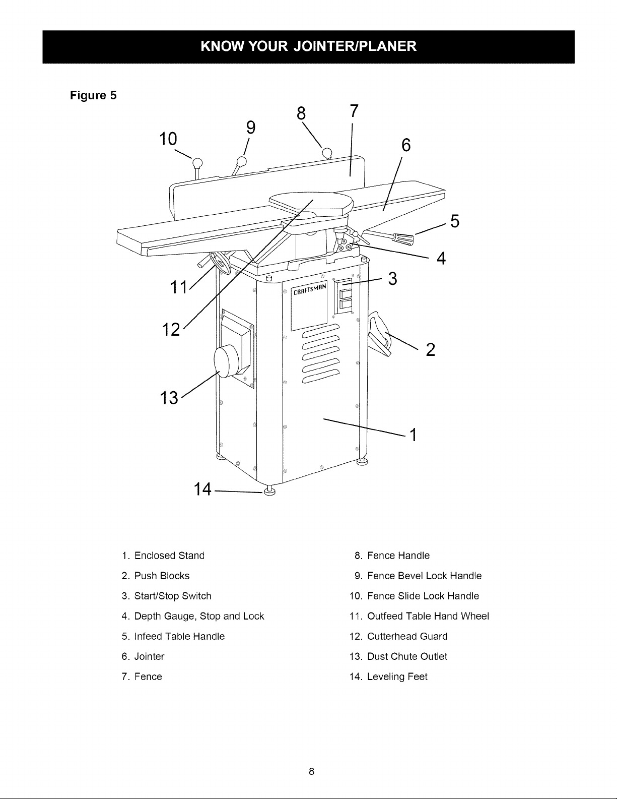
Figure 5
10 /
9
8
\
7
6
5
4
11
12
13
1. Enclosed Stand
3
2
8. Fence Handle
2. Push Blocks
3. Start/Stop Switch
4. Depth Gauge, Stop and Lock
5. Infeed Table Handle
6. Jointer
7. Fence
9. Fence Bevel Lock Handle
10. Fence Slide Lock Handle
11. Outfeed Table Hand Wheel
12. Cutterhead Guard
13. Dust Chute Outlet
14. Leveling Feet
8
F'!q,vlvhl_1_ii_[cll
TO AVOID SERIOUS INJURY AND DAMAGE TO THE
JOINTER/PLAN ER:
,
DO NOT assemble the Jointer/Planer until you are
sure the tool IS NOT plugged in.
,
DO NOT assemble the Jointer/Planer until you are
sure the power switch is in the "OFF" position.
,
DO NOT assemble the Jointer/Planer until you have
read and understood the entire Owner's Manual.
,
Assemble the other three legs to the enclosed stand
base in the same manner as in STEP 1. Hand
tighten all hex nuts at this point.
Leg (qty. 4)
Enclosed Stand Bottom Plate
M6 x 12mm Hex Head Screw (qty. 8)
M6 Flat Washer (qty. 8)
M6 Hex Nut (qty. 8)
4. DO NOT assemble Jointer/Planer if any parts are
missing or damaged.
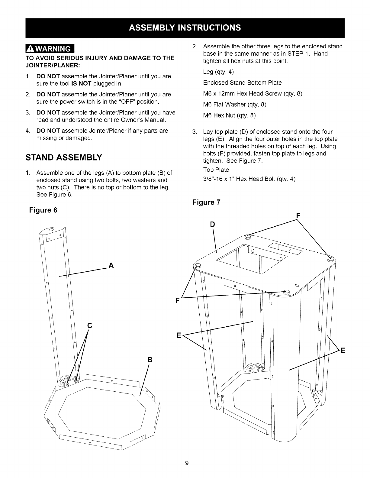
STAND ASSEMBLY
,
Assemble one of the legs (A) to bottom plate (B) of
enclosed stand using two bolts, two washers and
two nuts (C). There is no top or bottom to the leg.
See Figure 6.
Figure 6
A
F
,
Lay top plate (D) of enclosed stand onto the four
legs (E). Align the four outer holes in the top plate
with the threaded holes on top of each leg. Using
bolts (F) provided, fasten top plate to legs and
tighten. See Figure 7.
Top Plate
3/8"-16 x 1" Hex Head Bolt (qty. 4)
Figure 7
F
D
E
E
B
9
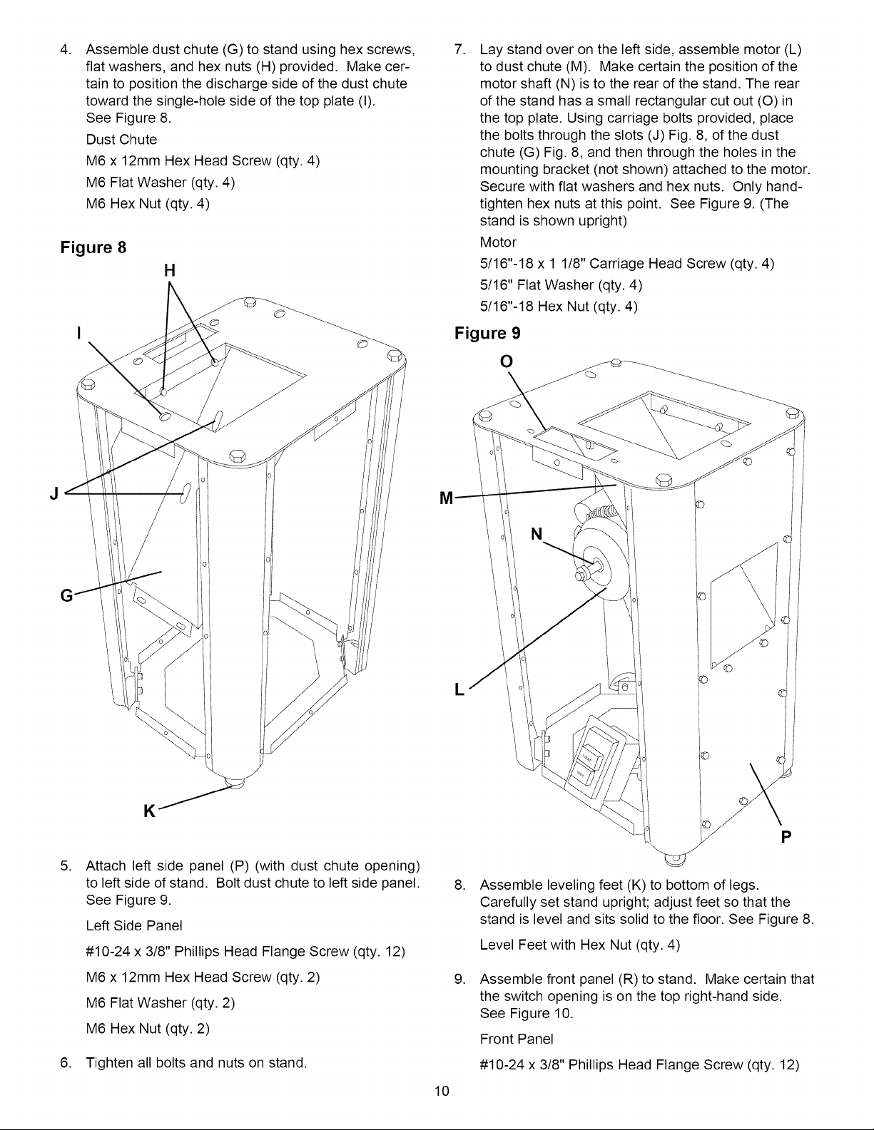
,
Assemble dust chute (G) to stand using hex screws,
flat washers, and hex nuts (H) provided. Make cer-
tain to position the discharge side of the dust chute
toward the single-hole side of the top plate (I).
See Figure 8.
Dust Chute
M6 x 12mm Hex Head Screw (qty. 4)
M6 Flat Washer (qty. 4)
M6 Hex Nut (qty. 4)
Figure 8
H
,
Lay stand over on the left side, assemble motor (L)
to dust chute (M). Make certain the position of the
motor shaft (N) is to the rear of the stand. The rear
of the stand has a small rectangular cut out (O) in
the top plate. Using carriage bolts provided, place
the bolts through the slots (J) Fig. 8, of the dust
chute (G) Fig. 8, and then through the holes in the
mounting bracket (not shown) attached to the motor.
Secure with flat washers and hex nuts. Only hand-
tighten hex nuts at this point. See Figure 9. (The
stand is shown upright)
Motor
5/16"-18 x 1 1/8" Carriage Head Screw (qty. 4)
5/16" Flat Washer (qty. 4)
5/16"-18 Hex Nut (qty. 4)
Figure 9
O
K
,
Attach left side panel (P) (with dust chute opening)
to left side of stand. Bolt dust chute to left side panel.
See Figure 9.
Left Side Panel
#10-24 x 3/8" Phillips Head Flange Screw (qty. 12)
M6 x 12mm Hex Head Screw (qty. 2)
M6 Flat Washer (qty. 2)
M6 Hex Nut (qty. 2)
6. Tighten all bolts and nuts on stand.
10
L
©
,
Assemble leveling feet (K) to bottom of legs.
Carefully set stand upright; adjust feet so that the
stand is level and sits solid to the floor. See Figure 8.
Level Feet with Hex Nut (qty. 4)
,
Assemble front panel (R) to stand. Make certain that
the switch opening is on the top right-hand side.
See Figure 10.
Front Panel
#10-24 x 3/8" Phillips Head Flange Screw (qty. 12)
P
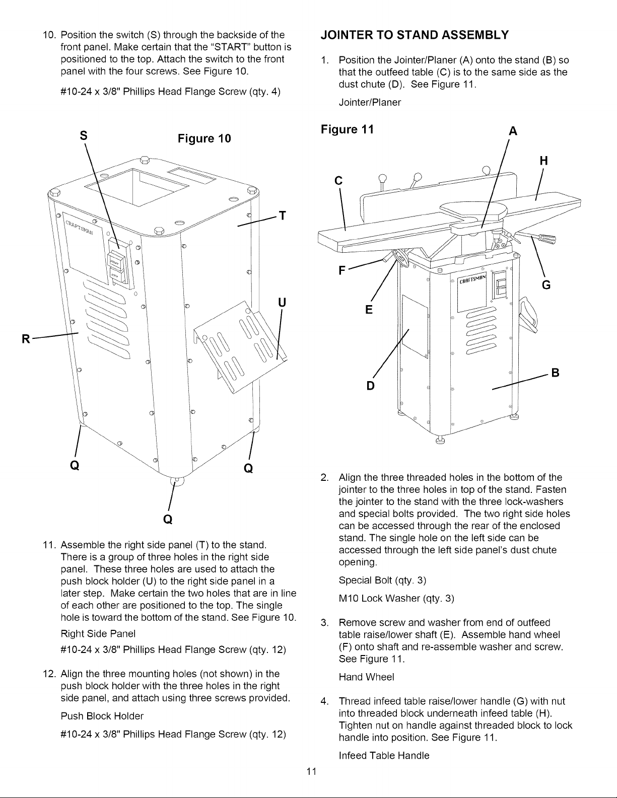
10.Positiontheswitch(S)throughthebacksideofthe
frontpanel.Makecertainthatthe"START"buttonis
positionedtothetop.Attachtheswitchtothefront
panelwiththefourscrews.SeeFigure10.
#10-24x 3/8"PhillipsHeadFlangeScrew(qty.4)
JOINTER TO STAND ASSEMBLY
,
Position the Jointer/Planer (A) onto the stand (B) so
that the outfeed table (C) is to the same side as the
dust chute (D). See Figure 11.
Jointer/Planer
S
Figure 10
Figure 11 A
H
C
T
F
G
U
R
E
B
D
11.
Assemble the right side panel (T) to the stand.
There is a group of three holes in the right side
panel. These three holes are used to attach the
push block holder (U) to the right side panel in a
later step. Make certain the two holes that are in line
of each other are positioned to the top. The single
hole is toward the bottom of the stand. See Figure 10.
Right Side Panel
#10-24 x 3/8" Phillips Head Flange Screw (qty. 12)
12.
Align the three mounting holes (not shown) in the
push block holder with the three holes in the right
side panel, and attach using three screws provided.
Push Block Holder
#10-24 x 3/8" Phillips Head Flange Screw (qty. 12)
,
Align the three threaded holes in the bottom of the
jointer to the three holes in top of the stand. Fasten
the jointer to the stand with the three lock-washers
and special bolts provided. The two right side holes
can be accessed through the rear of the enclosed
stand. The single hole on the left side can be
accessed through the left side panel's dust chute
opening.
Special Bolt (qty. 3)
M10 Lock Washer (qty. 3)
, Remove screw and washer from end of outfeed
table raise/lower shaft (E). Assemble hand wheel
(F) onto shaft and re-assemble washer and screw.
See Figure 11.
Hand Wheel
,
Thread infeed table raise/lower handle (G) with nut
into threaded block underneath infeed table (H).
Tighten nut on handle against threaded block to lock
handle into position. See Figure 11.
Infeed Table Handle
11
MOTOR PULLEY ASSEMBLY
To assemble motor pulley to motor shaft, back off the
two set screws in pulley so that pulley can slide onto
motor shaft. Make certain that the set screw side is
toward the motor body. Align the key in the motor shaft
with the key way in pulley. Slide pulley onto shaft until
end of shaft is flush with face of pulley.
Motor Pulley
BELT ASSEMBLY AND
PULLEY ALIGNMENT
,
Place V-belt in groove of cutterhead pulley and
motor pulley.
Belt
,
To properly align motor pulley to the cutterhead
pulley, place a straight edge on the outside face of
the cutterhead pulley. The motor and motor pulley
can be moved in or out and up or down until the
outside face of the motor pulley is vertically aligned
with the cutterhead pulley.
,
After proper alignment, tighten all bolts that attach
motor to dust chute.
4. Tighten both set screws.
Figure 12 A_
FENCE CARRIAGE ASSEMBLY
,
From the fence assembly (9) Fig. 4, remove the
E-clip (A), special hex nut (B), washer (C) and slide
trunnion bracket (D) from the bevel lock rod (E).
See Figure 13.
D
BELT TENSIONING
,
Proper belt tension is achieved when there is
approximately 1" deflection at the center of the belt
span using light finger pressure.
,
To achieve proper belt tension, loosen the four
motor attachment bolts. The motor can be moved
up or down to gain proper tension.
,
After achieving proper tension, check that there is
proper alignment of the pulleys. Then tighten all
bolts attaching the motor to the dust chute.
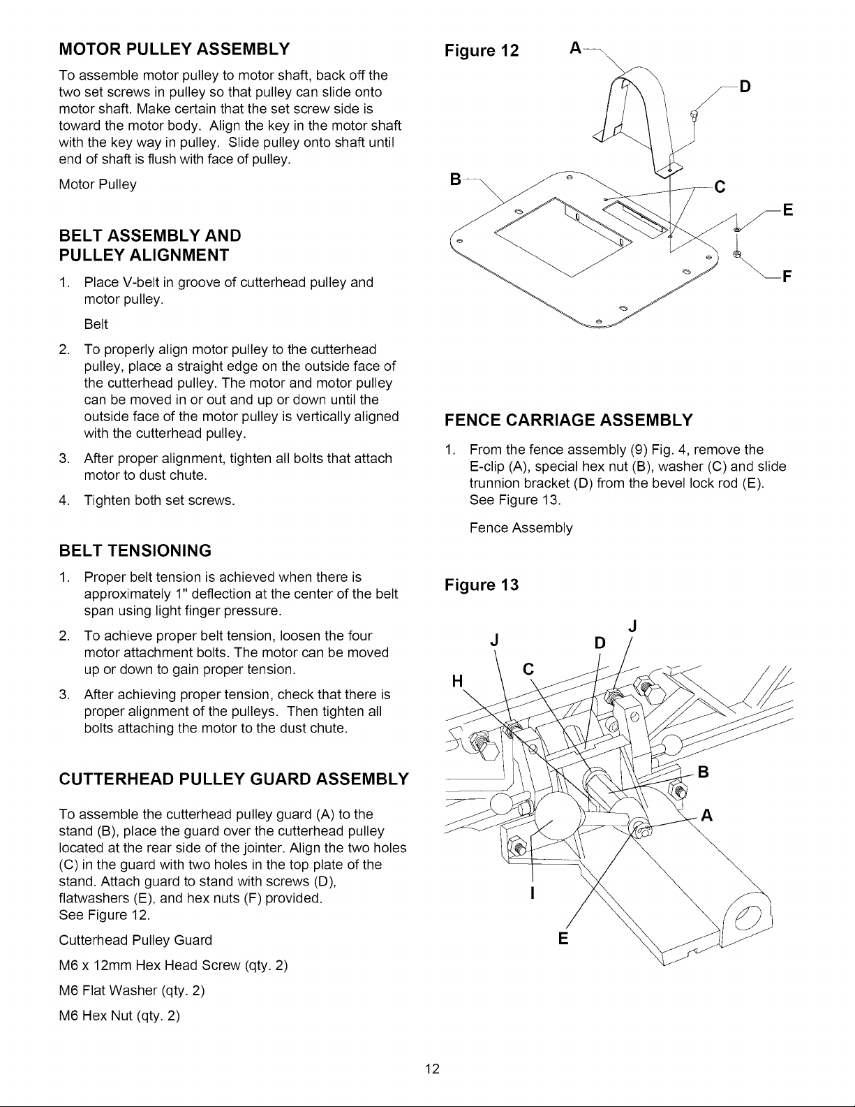
CUTTERHEAD PULLEY GUARD ASSEMBLY
To assemble the cutterhead pulley guard (A) to the
stand (B), place the guard over the cutterhead pulley
located at the rear side of the jointer. Align the two holes
(C) in the guard with two holes in the top plate of the
stand. Attach guard to stand with screws (D),
flatwashers (E), and hex nuts (F) provided.
See Figure 12.
Cutterhead Pulley Guard
Fence Assembly
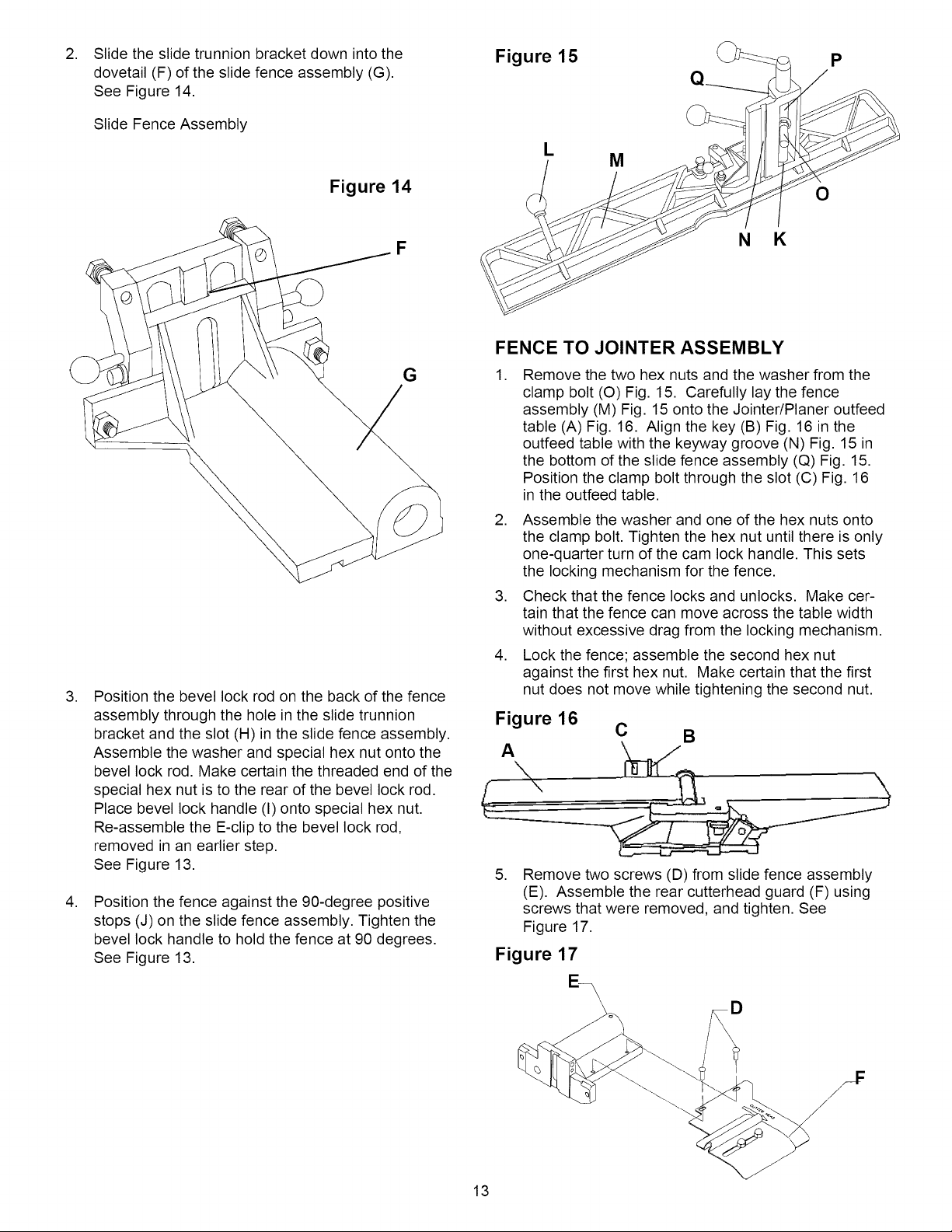
Figure 13
J
H
J
D
C
B
A
E
M6 x 12mm Hex Head Screw (qty. 2)
M6 Flat Washer (qty. 2)
M6 Hex Nut (qty. 2)
12
, Slide the slide trunnion bracket down into the
dovetail (F) of the slide fence assembly (G).
See Figure 14.
Slide Fence Assembly
Figure 15 J_ p
L
M
Figure 14
F
,
Position the bevel lock rod on the back of the fence
assembly through the hole in the slide trunnion
bracket and the slot (H) in the slide fence assembly.
Assemble the washer and special hex nut onto the
bevel lock rod. Make certain the threaded end of the
special hex nut is to the rear of the bevel lock rod.
Place bevel lock handle (I) onto special hex nut.
Re-assemble the E-clip to the bevel lock rod,
removed in an earlier step.
See Figure 13.
,
Position the fence against the 90-degree positive
stops (J) on the slide fence assembly. Tighten the
bevel lock handle to hold the fence at 90 degrees.
See Figure 13.
G
O
N K
FENCE TO JOINTER ASSEMBLY
, Remove the two hex nuts and the washer from the
clamp bolt (O) Fig. 15. Carefully lay the fence
assembly (M) Fig. 15 onto the Jointer/Planer outfeed
table (A) Fig. 16. Align the key (B) Fig. 16 in the
outfeed table with the keyway groove (N) Fig. 15 in
the bottom of the slide fence assembly (Q) Fig. 15.
Position the clamp bolt through the slot (C) Fig. 16
in the outfeed table.
2. Assemble the washer and one of the hex nuts onto
the clamp bolt. Tighten the hex nut until there is only
one-quarter turn of the cam lock handle. This sets
the locking mechanism for the fence.
3. Check that the fence locks and unlocks. Make cer-
tain that the fence can move across the table width
without excessive drag from the locking mechanism.
4. Lock the fence; assemble the second hex nut
against the first hex nut. Make certain that the first
nut does not move while tightening the second nut.
Figure 16
A
,
Remove two screws (D) from slide fence assembly
(E). Assemble the rear cutterhead guard (F) using
screws that were removed, and tighten. See
Figure 17.
Figure 17
C B
13
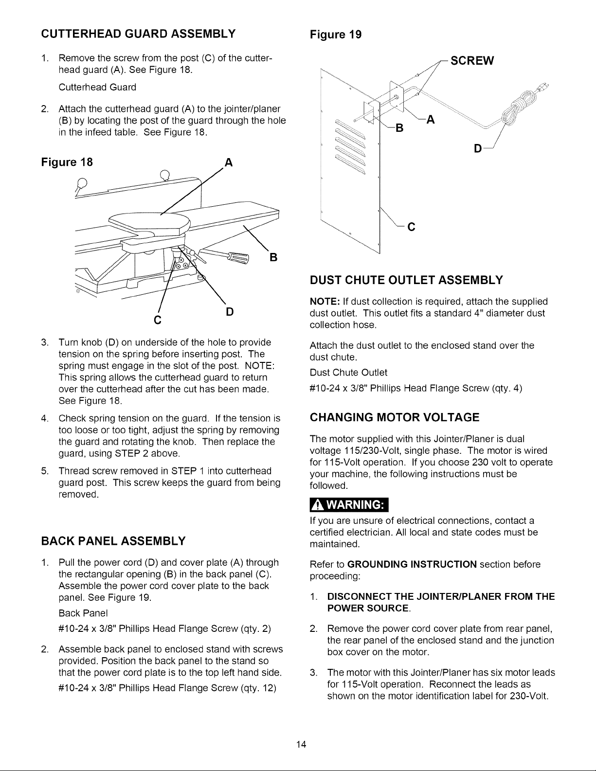
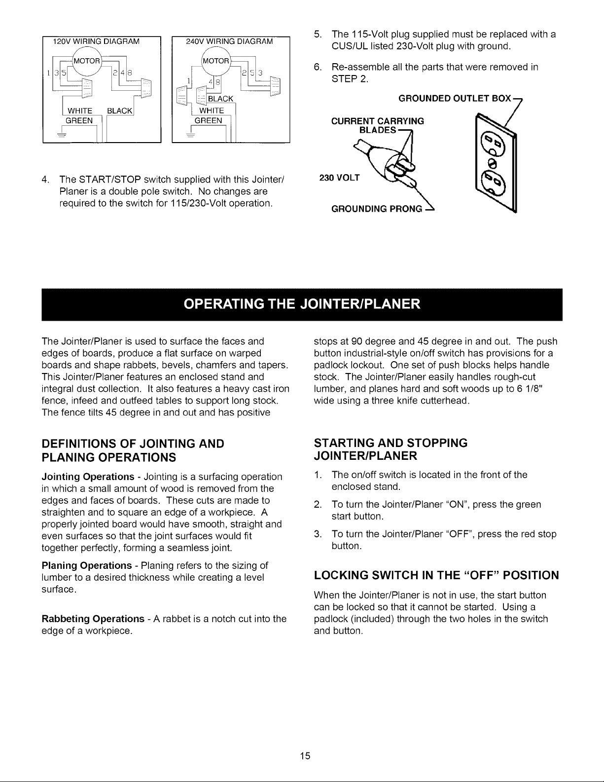
CUTTERHEAD GUARD ASSEMBLY Figure 19
1. Remove the screw from the post (C) of the cutter-
head guard (A). See Figure 18.
Cutterhead Guard
2. Attach the cutterhead guard (A) to the jointer/planer
(B) by locating the post of the guard through the hole
in the infeed table. See Figure 18.
Figure 18 A
D
C
SCREW
A
C
B
DUST CHUTE OUTLET ASSEMBLY
NOTE: If dust collection is required, attach the supplied
dust outlet. This outlet fits a standard 4" diameter dust
collection hose.
,
Turn knob (D) on underside of the hole to provide
tension on the spring before inserting post. The
spring must engage in the slot of the post. NOTE:
This spring allows the cutterhead guard to return
over the cutterhead after the cut has been made.
See Figure 18.
,
Check spring tension on the guard. If the tension is
too loose or too tight, adjust the spring by removing
the guard and rotating the knob. Then replace the
guard, using STEP 2 above.
,
Thread screw removed in STEP 1 into cutterhead
guard post. This screw keeps the guard from being
removed.
BACK PANEL ASSEMBLY
,
Pull the power cord (D) and cover plate (A) through
the rectangular opening (B) in the back panel (C).
Assemble the power cord cover plate to the back
panel. See Figure 19.
Back Panel
#10-24 x 3/8" Phillips Head Flange Screw (qty. 2)
,
Assemble back panel to enclosed stand with screws
provided. Position the back panel to the stand so
that the power cord plate is to the top left hand side.
#10-24 x 3/8" Phillips Head Flange Screw (qty. 12)
Attach the dust outlet to the enclosed stand over the
dust chute.
Dust Chute Outlet
#10-24 x 3/8" Phillips Head Flange Screw (qty. 4)
CHANGING MOTOR VOLTAGE
The motor supplied with this Jointer/Planer is dual
voltage 115/230-Volt, single phase. The motor is wired
for 115-Volt operation. If you choose 230 volt to operate
your machine, the following instructions must be
followed.
r!lVlVl_,1 _3_II _[e.]cB
If you are unsure of electrical connections, contact a
certified electrician. All local and state codes must be
maintained.
Refer to GROUNDING INSTRUCTION section before
proceeding:
1. DISCONNECT THE JOINTER/PLANER FROM THE
POWER SOURCE.
2. Remove the power cord cover plate from rear panel,
the rear panel of the enclosed stand and the junction
box cover on the motor.
3. The motor with this Jointer/Planer has six motor leads
for 115-Volt operation. Reconnect the leads as
shown on the motor identification label for 230-Volt.
14
120V WIRING DIAGRAM
240V WIRING DIAGRAM
5. The 115-Volt plug supplied must be replaced with a
CUS/UL listed 230-Volt plug with ground.
6. Re-assemble all the parts that were removed in
STEP 2.
GROUNDED OUTLET
GREEN
I--
GREEN 1
4. The START/STOP switch supplied with this Jointer/
Planer is a double pole switch. No changes are
required to the switch for 115/230-Volt operation.
The Jointer/Planer is used to surface the faces and
edges of boards, produce a flat surface on warped
boards and shape rabbets, bevels, chamfers and tapers.
This Jointer/Planer features an enclosed stand and
integral dust collection. It also features a heavy cast iron
fence, infeed and outfeed tables to support long stock.
The fence tilts 45 degree in and out and has positive
CURRENT CARRYING
230 VOLT __
GROUNDING PRONG
stops at 90 degree and 45 degree in and out. The push
button industrial-style on/off switch has provisions for a
padlock lockout. One set of push blocks helps handle
stock. The Jointer/Planer easily handles rough-cut
lumber, and planes hard and soft woods up to 6 1/8"
wide using a three knife cutterhead.
DEFINITIONS OF JOINTING AND
PLANING OPERATIONS
Jointing Operations - Jointing is a surfacing operation
in which a small amount of wood is removed from the
edges and faces of boards. These cuts are made to
straighten and to square an edge of a workpiece. A
properly jointed board would have smooth, straight and
even surfaces so that the joint surfaces would fit
together perfectly, forming a seamless joint.
Planing Operations - Planing refers to the sizing of
lumber to a desired thickness while creating a level
surface.
Rabbeting Operations - A rabbet is a notch cut into the
edge of a workpiece.
STARTING AND STOPPING
JOINTER/PLANER
1. The on/off switch is located in the front of the
enclosed stand.
2. To turn the Jointer/Planer "ON", press the green
start button.
3. To turn the Jointer/Planer "OFF", press the red stop
button.
LOCKING SWITCH IN THE "OFF" POSITION
When the Jointer/Planer is not in use, the start button
can be locked so that it cannot be started. Using a
padlock (included) through the two holes in the switch
and button.
15
INFEED TABLE OPERATION
1. To raise or lower the infeed table, loosen the infeed
table lock handle (A). To loosen handle, turn
counterclockwise; to tighten, turn handle clockwise.
See Figure 20.
Figure 20
C
D
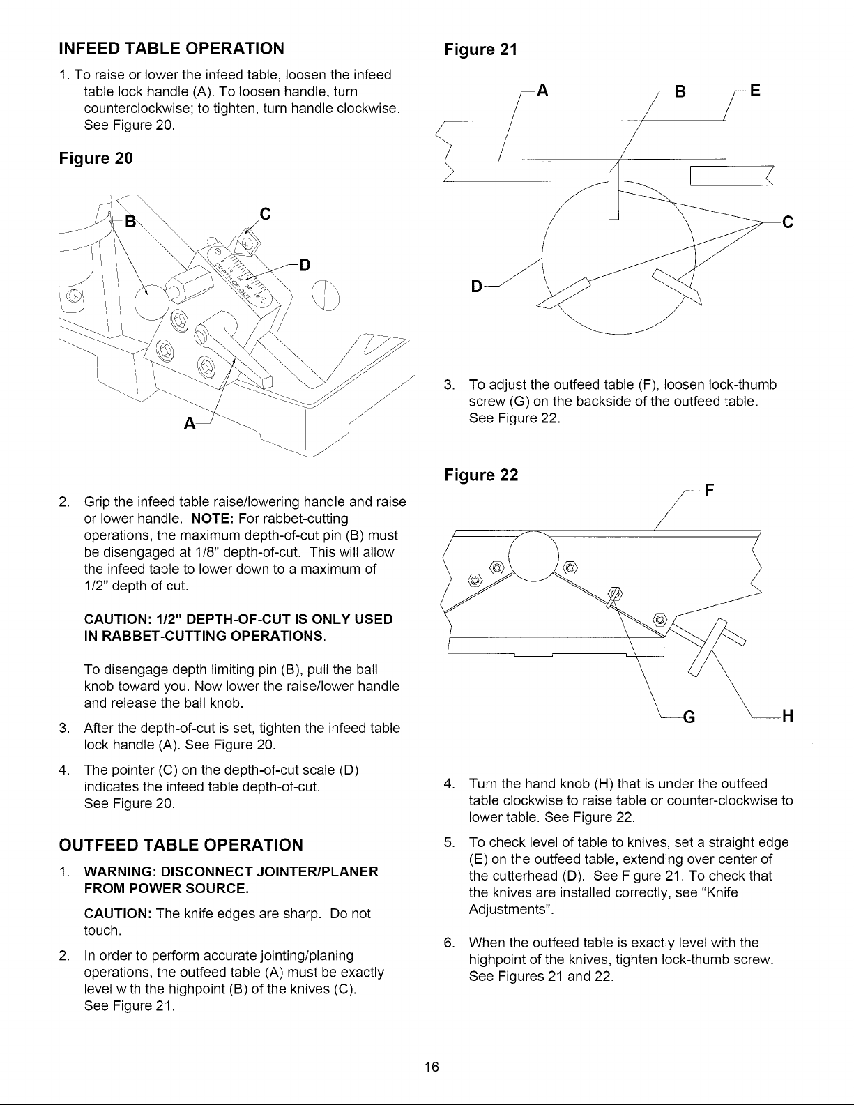
Figure 21
! <
D
3. To adjust the outfeed table (F), loosen lock-thumb
screw (G) on the backside of the outfeed table.
See Figure 22.
,
Grip the infeed table raise/lowering handle and raise
or lower handle. NOTE: For rabbet-cutting
operations, the maximum depth-of-cut pin (B) must
be disengaged at 1/8" depth-of-cut. This will allow
the infeed table to lower down to a maximum of
1/2" depth of cut.
CAUTION: 1/2" DEPTH-OF-CUT IS ONLY USED
IN RABBET-CUTTING OPERATIONS.
To disengage depth limiting pin (B), pull the ball
knob toward you. Now lower the raise/lower handle
and release the ball knob.
,
After the depth-of-cut is set, tighten the infeed table
lock handle (A). See Figure 20.
,
The pointer (C) on the depth-of-cut scale (D)
indicates the infeed table depth-of-cut.
See Figure 20.
OUTFEED TABLE OPERATION
1. WARNING: DISCONNECT JOINTER/PLANER
FROM POWER SOURCE.
CAUTION: The knife edges are sharp. Do not
touch.
,
In order to perform accurate jointing/planing
operations, the outfeed table (A) must be exactly
level with the highpoint (B) of the knives (C).
See Figure 21.
Figure 22
@
,
Turn the hand knob (H) that is under the outfeed
table clockwise to raise table or counter-clockwise to
lower table. See Figure 22.
,
To check level of table to knives, set a straight edge
(E) on the outfeed table, extending over center of
the cutterhead (D). See Figure 21. To check that
the knives are installed correctly, see "Knife
Adjustments".
,
When the outfeed table is exactly level with the
highpoint of the knives, tighten lock-thumb screw.
See Figures 21 and 22.
16
 Loading...